WO2018079770A1 - 電磁弁、及び飲料供給装置 - Google Patents
電磁弁、及び飲料供給装置 Download PDFInfo
- Publication number
- WO2018079770A1 WO2018079770A1 PCT/JP2017/039100 JP2017039100W WO2018079770A1 WO 2018079770 A1 WO2018079770 A1 WO 2018079770A1 JP 2017039100 W JP2017039100 W JP 2017039100W WO 2018079770 A1 WO2018079770 A1 WO 2018079770A1
- Authority
- WO
- WIPO (PCT)
- Prior art keywords
- port
- electromagnetic valve
- valve
- inlet port
- circulation
- Prior art date
- Legal status (The legal status is an assumption and is not a legal conclusion. Google has not performed a legal analysis and makes no representation as to the accuracy of the status listed.)
- Ceased
Links
Images




Classifications
-
- B—PERFORMING OPERATIONS; TRANSPORTING
- B67—OPENING, CLOSING OR CLEANING BOTTLES, JARS OR SIMILAR CONTAINERS; LIQUID HANDLING
- B67D—DISPENSING, DELIVERING OR TRANSFERRING LIQUIDS, NOT OTHERWISE PROVIDED FOR
- B67D1/00—Apparatus or devices for dispensing beverages on draught
- B67D1/07—Cleaning beverage-dispensing apparatus
-
- F—MECHANICAL ENGINEERING; LIGHTING; HEATING; WEAPONS; BLASTING
- F16—ENGINEERING ELEMENTS AND UNITS; GENERAL MEASURES FOR PRODUCING AND MAINTAINING EFFECTIVE FUNCTIONING OF MACHINES OR INSTALLATIONS; THERMAL INSULATION IN GENERAL
- F16K—VALVES; TAPS; COCKS; ACTUATING-FLOATS; DEVICES FOR VENTING OR AERATING
- F16K31/00—Actuating devices; Operating means; Releasing devices
- F16K31/02—Actuating devices; Operating means; Releasing devices electric; magnetic
- F16K31/06—Actuating devices; Operating means; Releasing devices electric; magnetic using a magnet, e.g. diaphragm valves, cutting off by means of a liquid
-
- F—MECHANICAL ENGINEERING; LIGHTING; HEATING; WEAPONS; BLASTING
- F16—ENGINEERING ELEMENTS AND UNITS; GENERAL MEASURES FOR PRODUCING AND MAINTAINING EFFECTIVE FUNCTIONING OF MACHINES OR INSTALLATIONS; THERMAL INSULATION IN GENERAL
- F16K—VALVES; TAPS; COCKS; ACTUATING-FLOATS; DEVICES FOR VENTING OR AERATING
- F16K31/00—Actuating devices; Operating means; Releasing devices
- F16K31/02—Actuating devices; Operating means; Releasing devices electric; magnetic
- F16K31/06—Actuating devices; Operating means; Releasing devices electric; magnetic using a magnet, e.g. diaphragm valves, cutting off by means of a liquid
- F16K31/0644—One-way valve
- F16K31/0655—Lift valves
-
- B—PERFORMING OPERATIONS; TRANSPORTING
- B67—OPENING, CLOSING OR CLEANING BOTTLES, JARS OR SIMILAR CONTAINERS; LIQUID HANDLING
- B67D—DISPENSING, DELIVERING OR TRANSFERRING LIQUIDS, NOT OTHERWISE PROVIDED FOR
- B67D1/00—Apparatus or devices for dispensing beverages on draught
- B67D2001/0093—Valves
Definitions
- the present invention relates to an electromagnetic valve capable of sterilizing a seal portion in a closed state, and a beverage supply device such as a water server equipped with the electromagnetic valve.
- a water server which is a beverage supply device has a tank for storing drinking water in a piping system, and as a means for sterilizing the piping system, for heating the drinking water in the tank to a sterilizable temperature.
- a heating means, a pump for supplying high-temperature water in the tank toward the piping system, and a circulation line for returning the high-temperature water sent to the piping system by the pump to the tank again Has been proposed.
- Such a water server maintains the piping system in a state where microorganisms are not propagated by periodically performing a sterilization process in which high-temperature water is supplied to the piping system by the above-mentioned pump or natural circulation (convection). To do.
- the water server 100 includes a drinking water container 102, a cold water tank 103 that receives drinking water dropped from the drinking water container 102, a hot water tank 105 that receives drinking water from the cold water tank 103, and the cold water in the cold water tank 103 as a drinking container
- the hot water tank 105 is provided with a heater (not shown), and the cold water tank 103 is provided with a cooler (not shown).
- the cold water injection unit 107 of the water server 100 is provided with an electromagnetic valve 110 shown in FIG.
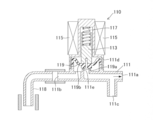
- the electromagnetic valve 110 includes a body portion 111.
- the body portion 111 is connected to an inlet port 111a into which drinking water flows, a valve box 111d connected to the inlet port 111a, and a valve box 111d.
- Outlet port 111b is shown in FIG. 8.
- the electromagnetic valve 110 includes a diaphragm (valve element) 119 that is disposed in the valve box 111d and opens and closes a conduit between the inlet port 111a and the outlet port 111b, a movable core portion 113 that is connected to the diaphragm 119, and a movable iron core.
- An object of the present invention is to provide an electromagnetic valve and a beverage supply device that can sufficiently sterilize the inside of the electromagnetic valve and have high sterilization efficiency.
- the present invention is configured as follows.
- (Aspect 1) A valve box, an inlet port for flowing beverage into the valve box, an outlet port for flowing beverage from the valve box, and a movable housed in the valve box between the inlet port and the outlet port A center portion, a seal portion provided on one end side of the movable core portion and closing the outlet port, and a seal portion provided on the other end side of the movable core portion and biasing the seal portion so as to close the outlet port.
- An electromagnetic valve comprising an urging member, wherein the electromagnetic valve is connected to the inter-port flow path for allowing a beverage to flow between the inlet port and the outlet port, and to the inter-port flow path on the outlet port side.
- a solenoid port wherein the sterilization medium flows between the inlet port and the circulation port via the inter-port flow path in a state where the seal portion closes the outlet port.
- the inter-port flow path is one or a plurality of grooves formed on an inner surface of the valve box or an outer surface of the movable core,
- An electromagnetic valve which is a space formed between an inner surface and an outer surface of the movable core.
- the circulation port is provided on a side wall of the valve box adjacent to the outlet port.
- Aspect 4 The electromagnetic valve according to any one of aspects 1 to 3, wherein the circulation port is arranged at a predetermined angle with respect to a longitudinal direction of the electromagnetic valve.
- the valve box includes a movable core portion accommodating portion that accommodates the movable core portion so as to advance and retreat, and the movable core portion accommodating portion.
- the diameter of the solenoid valve is larger than the diameter of the inlet port and / or the outlet port.
- the movable core portion is a movable iron core portion, and the electromagnetic valve includes a coil portion for moving the movable iron core portion by magnetic force. ,solenoid valve.
- the biasing member is a spring
- the electromagnetic valve includes an accommodating portion that accommodates the spring.
- the accommodating portion is a concave accommodating portion provided on the other end side of the movable core portion, and the spring is interposed between the inlet port and the concave accommodating portion. Is accommodated, solenoid valve.
- the recess-shaped accommodating portion is provided with one or a plurality of slits, and the inter-port flow path and the inlet port communicate with each other through the slits. valve.
- the electromagnetic valve includes an extension pipe portion that extends from the inlet port into the valve box, and the storage portion includes the extension pipe portion and the valve box. An electromagnetic valve, which is an annular housing portion formed between them.
- the electromagnetic valve according to aspect 10 wherein the extension pipe portion is provided with one or more slits, and the inter-port flow path and the inlet port communicate with each other through the slits. .
- Aspect 12 The electromagnetic valve according to Aspect 10 or 11, wherein the extension pipe portion is provided with an opening at an end thereof, and the inter-port passage and the inlet port are communicated with each other through the opening.
- Aspect 13 The electromagnetic valve according to any one of aspects 1 to 12, wherein the circulation port is provided in a lower part of the valve box.
- Aspect 14 The electromagnetic valve according to any one of aspects 1 to 13, wherein the sterilizing medium is hot water.
- a beverage supply device comprising the electromagnetic valve according to any one of aspects 1 to 14.
- Aspect 16 The beverage supply apparatus according to Aspect 15, wherein a heating member is provided in a pipe line connected to the circulation port or the inlet port.
- the present invention can reliably sterilize the inside of the solenoid valve when the solenoid valve is closed. Furthermore, according to the present invention, the periphery of the seal portion, the groove portion, and the urging member can be reliably sterilized with the electromagnetic valve closed.
- Embodiments in which the electromagnetic valve and beverage supply device of the present invention are applied to a water server electromagnetic valve and a water server will be described below.
- the water supply structure of the water server of each embodiment of the present invention is the same as that of the water server of FIG. 7, but includes an electromagnetic valve of each embodiment described later instead of the electromagnetic valve of the water server of FIG. 7.
- the electromagnetic valve and water server of each embodiment of the present invention have an electromagnetic valve that can sterilize the periphery of the seal portion of the electromagnetic valve when the flow path is sterilized.
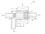
- the electromagnetic valve 10 includes a valve box (body part) 11 that houses a valve body such as a seal part 19 and the like that will be described later and constitutes a flow path that is opened and closed by the seal part 19, and the valve box 11 receives drinking water.
- a valve box (body part) 11 that houses a valve body such as a seal part 19 and the like that will be described later and constitutes a flow path that is opened and closed by the seal part 19, and the valve box 11 receives drinking water.
- An inlet port 11a, an outlet port 11b through which drinking water flows out, a circulation port 11c through which a sterilizing medium (hot water, hot water, or a sterilizing agent) circulates, and a large-diameter pipe portion 11d communicating with each port are provided.
- the inlet port 11a, the large-diameter pipe portion 11d, and the outlet port 11b are linearly arranged, and the circulation port 11c has a predetermined angle with respect to the longitudinal direction of the electromagnetic valve 10 on the outlet port 11b side. Then, it is connected to the large diameter pipe part (movable core part accommodating part) 11d.
- the predetermined angle may preferably be in the range of 45 degrees to 135 degrees, more preferably in the range of 80 degrees to 100 degrees, and even more preferably substantially perpendicular.
- the inner diameter of the large diameter pipe portion 11d is formed larger than the inner diameter of each port.
- the circulation port 11c is provided on the side wall of the valve box 11 adjacent to the outlet port 11b.
- the hot water is preferably water heated to a range of 60 to 100 ° C., more preferably water heated to a range of 80 to 100 ° C.
- the electromagnetic valve 10 is in contact with the inner surface of the large-diameter pipe portion 11d and can move forward and backward along its longitudinal direction, and the movable core portion 13 in the large-diameter pipe portion 11d.
- a seal portion 19 that can close the outlet port 11b, a return spring (biasing member) 17 that biases the movable core portion 13 toward the outlet port 11b, and a large-diameter pipe portion 11d.
- a coil portion 15 for moving the movable core portion 13 with a magnetic force.
- the spring 17 is provided between the other end (right end) of the movable core 13 and the inlet port 11a.
- the seal part 19 is formed in a disk shape from a flexible member such as rubber.
- the diameter of the seal part 19 is smaller than the diameter of the movable core part 13 and larger than the opening diameter of the outlet port 11b.
- the movable iron core portion 13 has an elongated cylindrical shape, and one or a plurality of groove portions 13a through which water can flow along the longitudinal direction is formed on the outer peripheral curved surface.
- the inter-port flow path connecting the inlet port 11a and the outlet port 11b is configured by the groove 13a.
- One or a plurality of groove portions may be formed along the longitudinal direction on the inner surface of the large-diameter pipe portion 11d instead of the outer surface of the movable iron core portion 13.
- a concave accommodating portion 13 b that accommodates the spring 17 is formed at the other end (the right end in FIG. 1) of the movable core portion 13.
- One or a plurality of slits 13c that allow water to flow are formed in a portion of the movable core portion 13 where the groove portion 13a and the accommodating portion 13b overlap.
- the electromagnetic valve 10 is in a closed state in which the movable iron core portion 13 and the seal portion 19 are advanced and the seal portion 19 closes the outlet port 11b.
- a sterilization medium hot water, hot water, or a sterilizing agent
- the sterilization medium flows into the inlet port 11a of the solenoid valve 10 as a forward flow
- the sterilization medium is stored in the housing portion 13b, the one or more slits 13c, the one or more grooves 13a, and the seal portion 19.
- the sterilizing medium flows in the order of the surroundings and the circulation port 11c, flows out to the outside of the solenoid valve 10, and circulates through a circulation pipe which will be described later. Further, when the sterilizing medium flows into the circulation port 11c of the electromagnetic valve 10 as a reverse flow, the sterilizing medium surrounds the seal portion 19, one or a plurality of grooves 13a, one or a plurality of slits 13c, a housing portion 13b, an inlet It flows in the order of the port 11a, flows out of the electromagnetic valve 10, and circulates through a circulation pipe which will be described later.
- the sterilizing medium can be made to flow only in the forward flow, only in the reverse flow, or alternately switched between the forward flow and the reverse flow.
- the solenoid valve 10 is in an open state in which the movable core portion 13 and the seal portion 19 are retracted and the seal portion 19 opens the outlet port 11b.
- the drinking water flows into the inlet port 11a of the electromagnetic valve 10 from a cold water tank (not shown)
- the drinking water is stored in the accommodating portion 13b, the one or more slits 13c, and the one or more grooves 13a.
- the seal part 19 flows out from the outlet port 11b to the outside of the solenoid valve 10 (cold water injection part).
- the pipe line connected to the circulation port 11c is closed by a valve (not shown)
- the drinking water does not flow out to the circulation port 11c side.
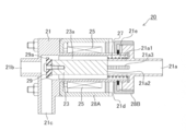
- the electromagnetic valve 20 includes a valve box (body part) 21 that houses a valve body such as a seal part 29, which will be described later, and constitutes a flow path that is opened and closed by the seal part 29, and drinking water flows into the valve box 21.
- An inlet port 21a, an outlet port 21b through which drinking water flows out, a circulation port 21c through which a sterilizing medium (hot water, hot water, or a sterilizing agent) circulates, and a large-diameter pipe portion 21d communicating with each port are provided.
- the inlet port 21a, the large-diameter pipe portion 21d, and the outlet port 21b are arranged in a straight line, and the circulation port 21c is on the outlet port 21b side with respect to the longitudinal direction of the electromagnetic valve 10. And connected to the large-diameter pipe portion 21d. Further, as shown in FIGS. 3 and 4, the circulation port 21c is provided on the side wall of the valve box 21 adjacent to the outlet port 21b.
- the electromagnetic valve 20 is in contact with the inner surface of the large-diameter pipe portion 21d and can move forward and backward along the longitudinal direction thereof, and one end (left end) of the movable iron core portion 23 in the large-diameter pipe portion 21d.
- a seal portion 29 that can close the outlet port 21b, a return spring (biasing member) 27 that urges the movable core portion 23 toward the outlet port 21b.
- the coil part 25 for moving the movable core part 23 by magnetic force is provided.
- the spring 27 is provided between the other end (right end) of the movable core portion 23 and the inlet port 21a in the large-diameter pipe portion 21d.
- the seal part 29 is formed in a disk shape from a flexible member such as rubber.
- the seal part 29 further has a flange part 29a, and the diameter of the flange part 29a is smaller than the diameter of the movable core part 23 and larger than the diameter of the outlet port 21b.
- the movable iron core portion 23 has an elongated cylindrical shape, and one or a plurality of groove portions 23a through which water can flow along the longitudinal direction are formed on the outer peripheral curved surface.
- the inter-port flow path connecting the inlet port 21a and the outlet port 21b is configured by the groove 23a.
- One or more grooves may be formed not on the outer surface of the movable core portion 23 but on the inner surface of the large-diameter pipe portion 21d.
- an extension pipe part 21a1 is provided that extends the pipe line of the inlet port 21a into the large diameter pipe part 21d.
- An annular space formed between the outer surface of the extension tube portion 21a1 of the inlet port 21a and the inner surface of the large diameter tube portion 21d constitutes a housing portion 21e that houses the spring 27.
- An opening 21 a 2 is formed on the end surface of the extension pipe portion 21 a 1 that faces the movable core portion 23.
- One or more slits 21a3 are formed around the extension pipe part 21a1 in parallel with the longitudinal direction of the large diameter pipe part 21d.
- the opening 21a2 and the slit 21a3 allow water to flow between the inlet port 21a and the inside of the large diameter pipe portion 21d.
- the electromagnetic valve 20 is in a closed state in which the movable iron core portion 23 and the seal portion 29 are advanced and the seal portion 29 closes the outlet port 21 b.
- a sterilizing medium hot water, hot water, or a sterilizing agent
- the sterilization medium includes the opening 21a2, one or more slits 21a3, the accommodating portion 21e, one or more grooves 23a, and a seal.
- the sterilization medium flows in the order around the part 29, flows out of the electromagnetic valve 20, and circulates through a circulation line to be described later. Further, when the sterilization medium flows into the circulation port 21c of the electromagnetic valve 20 as a reverse flow, the sterilization medium flows around the seal portion 29, one or a plurality of groove portions 23a, a housing portion 21e, an opening 21a2, and one or more slits. It flows in the order of 21a3 and the inlet port 21a, flows out of the solenoid valve 20, and circulates through a circulation pipe which will be described later. Also in the second embodiment, the sterilization medium can be made to flow only in the forward flow, only in the reverse flow, or alternately switched between the forward flow and the reverse flow.
- the solenoid valve 20 is in an open state in which the movable core portion 23 and the seal portion 29 are retracted and the seal portion 29 opens the outlet port 21b.
- the drinking water flows from a cold water tank (not shown) into the inlet port 21a of the electromagnetic valve 20
- the drinking water is supplied to the extension pipe portion 21a1, one or a plurality of slits 21a3, the accommodating portion 12e, and one.
- the gas passes through the periphery of the plurality of groove portions 23 a and the seal portion 29 in order, and flows out from the outlet port 21 b to the outside of the electromagnetic valve 20. Since the circulation path connected to the circulation port 21c is closed by a valve (not shown), the drinking water does not flow out to the circulation port 21c side.
- the circulation line 30 will be described with reference to FIG.
- the circulation pipe 30 is provided with a heater (heating member) 31 below the pipe connected to the circulation port 11c. Since the solenoid valve 10 is arranged horizontally, the inlet port 11a and the outlet port 11b are arranged in the horizontal direction, and the circulation port 11c faces downward.
- the heater 31 heats the water in the pipe, the water is heated to become a sterilization medium (hot water), and the pipe is raised by convection, so that the circulation port 11 c and the solenoid valve 10 circulates in the order of the inlet port 11a.
- the circulation line 40 will be described with reference to FIG.
- the circulation pipe 40 is provided with a heater 41 (heating member) below the pipe connected to the circulation port 11c. Since the solenoid valve 10 is arranged vertically, the inlet port 11a and the outlet port 11b are arranged in the vertical direction, and the circulation port 11c faces the horizontal direction.
- the heater 41 heats the water in the pipe, the water is heated to become a sterilization medium (hot water), and the pipe is raised by convection, so that the circulation port 11c, the electromagnetic valve 10 circulates in the order of the inlet port 11a.
- the circulation line 50 will be described with reference to FIG.
- the circulation pipe 50 is provided with a heater (heating member) 51 in a pipe branching downward from a pipe connected to the inlet port 11a. Since the solenoid valve 10 is arranged horizontally, the inlet port 11a and the outlet port 11b are arranged in the horizontal direction, and the circulation port 11c faces downward.
- the heater 51 heats the water in the pipe
- the water is heated to become a sterilization medium (hot water), and the pipe is raised by convection, so that the inlet port 11a, the solenoid valve 10 circulates in the order of the circulation port 11c.
- the circulation line 60 will be described with reference to FIG.
- the circulation pipe 60 is provided with a heater (heating member) 61 in a pipe branching downward from a pipe connected to the inlet port 11a. Since the solenoid valve 10 is arranged vertically, the inlet port 11a and the outlet port 11b are arranged in the vertical direction, and the circulation port 11c faces the horizontal direction.
- the heater 61 heats the water in the pipe, the water is heated to become a sterilization medium (hot water), and the pipe is raised by convection, so that the inlet port 11a, the solenoid valve 10 circulates in the order of the circulation port 11c.
- the solenoid valve according to the first or second embodiment of the present invention can circulate the sterilization medium on the entire inner surface of the solenoid valve except the outlet port and the surface of the seal portion on the side closing the outlet port. Therefore, the entire solenoid valve can be efficiently heated to the sterilization temperature in a short time, and an appropriate sterilization effect can be obtained, and energy required for sterilization can be reduced as compared with the conventional case.
- the water server which supplies water was described as a drink supply apparatus provided with the solenoid valve 10 or 20
- this invention is not limited to a water server, For example, You may apply to the drink supply apparatus which supplies a soft drink.
- the solenoid valve 10 or 20 was provided in the drink supply apparatus, it is not limited to this,
- the liquid supply which supplies the arbitrary liquid which is not a drink to the said solenoid valve It can also be provided in the device.
Landscapes
- Engineering & Computer Science (AREA)
- General Engineering & Computer Science (AREA)
- Mechanical Engineering (AREA)
- Devices For Dispensing Beverages (AREA)
- Magnetically Actuated Valves (AREA)
Abstract
本発明の電磁弁(10)は、弁箱(11)と、弁箱(11)に飲料を流入する入口ポート(11a)と、弁箱(11)から飲料を流出する出口ポート(11b)と、入口ポート(11a)及び出口ポート(11b)の間で弁箱(11)に収容される可動鉄心部(13)と、可動鉄心部(13)の一端側に設けられ出口ポート(11b)を閉鎖するシール部(19)と、可動鉄心部(13)の他端側に設けられ出口ポート(11b)を閉鎖するようにシール部(19)を付勢するスプリング(17)とを備える。電磁弁(10)は、可動鉄心部(13)に形成される1つまたは複数の溝部(ポート間流路)(13a)と、循環ポート(11d)とを備え、シール部(19)が出口ポート(11b)を閉鎖した状態で、入口ポート(11a)及び循環ポート(11c)の間で、1つまたは複数の溝部(13a)を介して殺菌媒体が流通する。
Description
本発明は、閉鎖状態でシール部を殺菌可能な電磁弁、及びこの電磁弁を備えたウォータサーバ等の飲料供給装置に関する。
従来、飲料供給装置であるウォータサーバは、配管系統中に飲料水を貯留するタンクを有し、前記配管系統を殺菌処理する手段として、前記タンクの飲料水を殺菌可能な温度に加熱するための加熱手段と、前記タンク内の高温水を前記配管系統に向けて供給させるポンプと、前記ポンプによって前記配管系統に送られた前記高温水を再び前記タンクに戻すための循環管路とを備えるものが提案されている。
このようなウォータサーバは、上記ポンプや、自然循環(対流)によって高温水を配管系統に供給させる形態の殺菌処理を定期的に実施させることで、配管系統を微生物の繁殖していない状態に維持するものである。
上記ウォータサーバの一例を図7を用いて説明する。ウォータサーバ100は、飲料水容器102と、飲料水容器102から落下した飲料水を受け入れる冷水タンク103と、冷水タンク103から飲料水を受け入れる温水タンク105と、冷水タンク103内の冷水を飲料容器等に注水する冷水注水部107と、温水タンク105内の温水を飲料容器等に注水する温水注水部120とを備える。なお、温水タンク105には図示しないヒータが設けられ、冷水タンク103には図示しない冷却機が設けられている。ウォータサーバ100の冷水注水部107には、次の図8に示す電磁弁110が設けられる。
図8に示すように、電磁弁110はボディ部111を備え、このボディ部111は、飲料水が流入する入口ポート111aと、入口ポート111aに接続される弁箱111dと、弁箱111dに接続される出口ポート111bとを備える。
電磁弁110は、弁箱111d内に配置され入口ポート111aと出口ポート111bとの間の管路を開閉するダイヤフラム(弁体)119と、ダイヤフラム119に接続される可動鉄心部113と、可動鉄心部113を磁力で移動するためのコイル部115と、可動鉄心部113及びダイヤフラム119を弁座111eに向けて付勢するスプリング117と、出口ポート111bに接続される注水口部118とを備える。
図8に示すように電磁弁110が閉鎖すると、ダイヤフラム119のシール面119aが弁座111eに着座して、弁座111eの前後の流れを遮断する。この状態で、殺菌用の熱水が電磁弁110の循環ポート111cから入口ポート111aに流れる。しかし、このような電磁弁110の構造では、循環水洗浄時に熱水がダイヤフラム119のシール面119aの近傍まで流入しないため、電磁弁の殺菌に必要な温度まで上昇するのに時間がかかっていた。さらに、熱水が直接接触しないダイヤフラム119の外周部119bの下方には空間が形成されており、特にこの空間における殺菌に必要な温度まで上昇するのに時間がかかっていた。
図8に示したように、熱水洗浄時の流路が電磁弁主要部(ダイヤフラム119のシール面119a、外周部119b)を通過しないため、電磁弁の殺菌に時間を要するため、エネルギー効率が悪くなっている。さらに、熱水が直接接触しないダイヤフラムの外周部には空間を有しており、特にこの空間における殺菌のためのエネルギー効率が悪かった。
本発明は、電磁弁の内部が十分に殺菌可能で、かつ、殺菌効率の良い電磁弁及び飲料供給装置を提供することを目的とする。
上記課題を解決するために、本発明は、次の通り構成される。
(態様1)弁箱と、前記弁箱に飲料を流入する入口ポートと、前記弁箱から飲料を流出する出口ポートと、前記入口ポート及び前記出口ポートの間で前記弁箱に収容される可動心部と、前記可動心部の一端側に設けられ前記出口ポートを閉鎖するシール部と、前記可動心部の他端側に設けられ前記出口ポートを閉鎖するように前記シール部を付勢する付勢部材とを備える、電磁弁であって、前記電磁弁は、前記入口ポートから前記出口ポートまでの間で飲料を流すポート間流路と、前記出口ポート側で前記ポート間流路に接続される循環ポートとを備え、前記シール部が前記出口ポートを閉鎖した状態で、前記入口ポート及び前記循環ポートの間で、前記ポート間流路を介して殺菌媒体が流通する、電磁弁。(態様2)態様1に記載の電磁弁において、前記ポート間流路は、前記弁箱の内面または前記可動心部の外面に形成された1つ又は複数の溝部であるか、前記弁箱の内面及び前記可動心部の外面の間に形成された空間である、電磁弁。(態様3)態様1または2に記載の電磁弁において、前記循環ポートは、前記出口ポートに隣接する前記弁箱の側壁に設けられる、電磁弁。(態様4)態様1~3のいずれか一項に記載の電磁弁において、前記循環ポートは、前記電磁弁の長手方向に対して所定の角度をなして配置される、電磁弁。
(態様1)弁箱と、前記弁箱に飲料を流入する入口ポートと、前記弁箱から飲料を流出する出口ポートと、前記入口ポート及び前記出口ポートの間で前記弁箱に収容される可動心部と、前記可動心部の一端側に設けられ前記出口ポートを閉鎖するシール部と、前記可動心部の他端側に設けられ前記出口ポートを閉鎖するように前記シール部を付勢する付勢部材とを備える、電磁弁であって、前記電磁弁は、前記入口ポートから前記出口ポートまでの間で飲料を流すポート間流路と、前記出口ポート側で前記ポート間流路に接続される循環ポートとを備え、前記シール部が前記出口ポートを閉鎖した状態で、前記入口ポート及び前記循環ポートの間で、前記ポート間流路を介して殺菌媒体が流通する、電磁弁。(態様2)態様1に記載の電磁弁において、前記ポート間流路は、前記弁箱の内面または前記可動心部の外面に形成された1つ又は複数の溝部であるか、前記弁箱の内面及び前記可動心部の外面の間に形成された空間である、電磁弁。(態様3)態様1または2に記載の電磁弁において、前記循環ポートは、前記出口ポートに隣接する前記弁箱の側壁に設けられる、電磁弁。(態様4)態様1~3のいずれか一項に記載の電磁弁において、前記循環ポートは、前記電磁弁の長手方向に対して所定の角度をなして配置される、電磁弁。
(態様5)態様1~4のいずれか一項に記載の電磁弁において、前記弁箱には、前記可動心部を進退自在に収容する可動心部収容部を備え、前記可動心部収容部の直径は、前記入口ポート及び/又は前記出口ポートの直径より大きい、電磁弁。(態様6)態様1~5のいずれか一項に記載の電磁弁において、前記可動心部が可動鉄心部であり、前記電磁弁は前記可動鉄心部を磁力で移動するためのコイル部を備える、電磁弁。(態様7)態様1~6のいずれか一項に記載の電磁弁において、前記付勢部材はスプリングであり、前記電磁弁は前記スプリングを収容する収容部を備える、電磁弁。(態様8)態様7に記載の電磁弁において、前記収容部は、前記可動心部の前記他端側に設けられた凹状収容部であり、前記入口ポート及び前記凹状収容部の間に前記スプリングが収容される、電磁弁。(態様9)態様8に記載の電磁弁において、前記凹部状収容部には1つまたは複数のスリットが設けられ、前記スリットを介して前記ポート間流路及び前記入口ポートが連通される、電磁弁。(態様10)態様7に記載の電磁弁において、前記電磁弁は、前記入口ポートから前記弁箱内に延長する延長管部を備え、前記収容部は、前記延長管部と前記弁箱との間に形成される環状収容部である、電磁弁。(態様11)態様10に記載の電磁弁において、前記延長管部には1つまたは複数のスリットが設けられ、前記スリットを介して前記ポート間流路及び前記入口ポートが連通される、電磁弁。
(態様12)態様10又は11に記載の電磁弁において、前記延長管部はその末端に開口が設けられ、前記開口を介して前記ポート間流路及び前記入口ポートが連通される、電磁弁。(態様13)態様1~12のいずれか一項に記載の電磁弁において、前記循環ポートは前記弁箱の下部に設けられる、電磁弁。(態様14)態様1~13のいずれか一項に記載の電磁弁において、前記殺菌媒体は、熱水である、電磁弁。(態様15)態様1~14のいずれか一項に記載の電磁弁を備える、飲料供給装置。(態様16)態様15に記載の飲料供給装置において、前記循環ポート又は前記入口ポートに接続される管路に加熱部材を備える、飲料供給装置。(態様17)態様16に記載の飲料供給装置において、前記シール部が前記出口ポートを閉鎖した状態で、前記加熱部材の加熱により生成した殺菌媒体が、前記循環ポート又は前記入口ポートを介して、前記電磁弁内に供給される、飲料供給装置。(態様18)態様16又は17に記載の飲料供給装置において、前記殺菌媒体が前記加熱部材に加熱されて生じた対流により、前記循環ポート又は前記入口ポートを介して、前記電磁弁内に供給される、飲料供給装置。(態様19)態様15~18のいずれか一項に記載の飲料供給装置において、前記電磁弁に殺菌媒体を循環させる循環管路を備える、飲料供給装置。(態様20)態様15~19のいずれか一項に記載の飲料供給装置であるウォータサーバ。(態様21)態様20に記載のウォータサーバは、冷水供給部側に前記電磁弁を備える、ウォータサーバ。
本発明は、電磁弁の閉鎖状態で電磁弁内部を確実に殺菌できる。さらに、本発明は、電磁弁の閉鎖状態で、シール部周囲、溝部、及び付勢部材も確実に殺菌できる。
本発明の電磁弁及び飲料供給装置を、ウォータサーバ用電磁弁及びウォータサーバに適用した各実施形態を以下説明する。なお、本発明の各実施形態のウォータサーバの給水構造は、図7のウォータサーバと同様であるが、図7のウォータサーバの電磁弁に換えて、後述する各実施形態の電磁弁を備える。本発明の各実施形態の電磁弁及びウォータサーバは、流路の殺菌時に電磁弁のシール部の周囲を殺菌できる電磁弁を有する。
(第1の実施形態)
本発明の第1の実施形態に係るウォータサーバ用電磁弁を、図1及び2を用いて説明する。電磁弁10は、後述のシール部19等の弁体を収容すると共にシール部19により開閉される流路を構成する弁箱(ボディ部)11を備え、弁箱11は、飲料水が流入する入口ポート11aと、飲料水が流出する出口ポート11bと、殺菌媒体(熱水、温水または殺菌剤)が循環する循環ポート11cと、各ポートに連通する大径管部11dとをそれぞれ備える。弁箱11において、入口ポート11a、大径管部11d、及び出口ポート11bは直線状に配置され、循環ポート11cは、出口ポート11b側で、電磁弁10の長手方向に対して所定の角度をなして大径管部(可動心部収容部)11dに接続される。所定の角度は、好ましくは、45度から135度の範囲、より好ましくは80度から100度の範囲、さらに好ましくはほぼ直角とすることができる。大径管部11dの内径は、各ポートの内径より大きく形成される。図1及び2に示すように、循環ポート11cは、出口ポート11bに隣接する弁箱11の側壁に設けられる。なお、熱水とは、好ましくは60から100℃の範囲に加熱した水、より好ましくは80から100℃の範囲に加熱した水、とすることができる。
本発明の第1の実施形態に係るウォータサーバ用電磁弁を、図1及び2を用いて説明する。電磁弁10は、後述のシール部19等の弁体を収容すると共にシール部19により開閉される流路を構成する弁箱(ボディ部)11を備え、弁箱11は、飲料水が流入する入口ポート11aと、飲料水が流出する出口ポート11bと、殺菌媒体(熱水、温水または殺菌剤)が循環する循環ポート11cと、各ポートに連通する大径管部11dとをそれぞれ備える。弁箱11において、入口ポート11a、大径管部11d、及び出口ポート11bは直線状に配置され、循環ポート11cは、出口ポート11b側で、電磁弁10の長手方向に対して所定の角度をなして大径管部(可動心部収容部)11dに接続される。所定の角度は、好ましくは、45度から135度の範囲、より好ましくは80度から100度の範囲、さらに好ましくはほぼ直角とすることができる。大径管部11dの内径は、各ポートの内径より大きく形成される。図1及び2に示すように、循環ポート11cは、出口ポート11bに隣接する弁箱11の側壁に設けられる。なお、熱水とは、好ましくは60から100℃の範囲に加熱した水、より好ましくは80から100℃の範囲に加熱した水、とすることができる。
また、電磁弁10は、大径管部11dの内面に当接しつつ、その長手方向に沿って進退可能な可動鉄心部(可動心部)13と、大径管部11d内で可動鉄心部13の一端(左端)に設けられ、出口ポート11bを閉鎖可能なシール部19と、可動鉄心部13を出口ポート11bに向けて付勢するリターンスプリング(付勢部材)17と、大径管部11dの外側に配置され、可動心部13を磁力で移動するためのコイル部15とを備える。なお、スプリング17は、可動心部13の他端(右端)と入口ポート11aとの間に設けられる。
シール部19はゴム等の可撓性部材から円盤状に形成される。シール部19の直径は、可動鉄心部13の直径よりも小さく、出口ポート11bの開口直径よりも大きい。可動鉄心部13は、細長い円柱状であり、その外周曲面上に長手方向に沿って水が流通可能な1つまたは複数の溝部13aが形成される。溝部13aによって、入口ポート11a及び出口ポート11bの間を接続するポート間流路が構成される。また、溝部は、可動鉄心部13の外面でなく、大径管部11dの内面に、その長手方向に沿って1つまたは複数形成してもよい。さらに、溝部を形成せずに、弁箱11の内面と可動鉄心部13の外面との間に、入口ポートから出口ポートまで空間を形成することにより、ポート間流路を構成してもよい。可動鉄心部13の他端(図1の右端)には、スプリング17を収容する凹状の収容部13bが形成される。可動鉄心部13の、溝部13a及び収容部13bが重なる部分には、水を流通可能とする1つまたは複数のスリット13cが形成される。
電磁弁10の閉鎖状態における殺菌媒体の流れを説明する。図1に示すように、電磁弁10は、可動鉄心部13及びシール部19が前進してシール部19が出口ポート11bを閉鎖した閉鎖状態にある。この閉鎖状態で、順流や逆流で殺菌媒体(熱水、温水または殺菌剤)を流すことができる。具体的には、順流として、殺菌媒体が電磁弁10の入口ポート11aに流入すると、殺菌媒体は、収容部13b、1つまたは複数のスリット13c、1つまたは複数の溝部13a、シール部19の周囲、循環ポート11cの順に流れ、電磁弁10の外部に流出して、後述する循環管路を通って循環する。また、逆流として、殺菌媒体が電磁弁10の循環ポート11cに流入すると、殺菌媒体は、シール部19の周囲、1つまたは複数の溝部13a、1つまたは複数のスリット13c、収容部13b、入口ポート11aの順に流れ、電磁弁10の外部に流出して、後述する循環管路を通って循環する。第1の実施形態においては、殺菌媒体を、順流のみで流すか、逆流のみで流すか、または、順流及び逆流を交互に切換えて流すことができる。
次に、電磁弁10の開放状態における飲料水の流れを説明する。図2に示すように、電磁弁10は、可動鉄心部13及びシール部19が後退してシール部19が出口ポート11bを開放した開放状態にある。この開放状態で、図示しない冷水タンクから飲料水(冷水)が電磁弁10の入口ポート11aに流入すると、飲料水は、収容部13b、1つまたは複数のスリット13c、1つまたは複数の溝部13a、シール部19の周囲を順に通って、出口ポート11bから電磁弁10の外部(冷水注水部)に流出する。なお、循環ポート11cに接続される管路は図示しない弁により閉鎖等されるため、飲料水は循環ポート11c側には流出しない。
(第2の実施形態)
第2の実施形態に係る電磁弁20を図3及び4を用いて説明する。電磁弁20は、後述のシール部29等の弁体を収容すると共にシール部29により開閉される流路を構成する弁箱(ボディ部)21を備え、弁箱21は、飲料水が流入する入口ポート21aと、飲料水が流出する出口ポート21bと、殺菌媒体(熱水、温水または殺菌剤)が循環する循環ポート21cと、各ポートに連通する大径管部21dとをそれぞれ備える。弁箱21において、入口ポート21a、大径管部21d、及び出口ポート21bは直線状に配置され、循環ポート21cは、出口ポート21b側で、電磁弁10の長手方向に対して前記所定の角度をなして大径管部21dに接続される。さらに、図3及び4に示すように、循環ポート21cは、出口ポート21bに隣接する弁箱21の側壁に設けられる。
第2の実施形態に係る電磁弁20を図3及び4を用いて説明する。電磁弁20は、後述のシール部29等の弁体を収容すると共にシール部29により開閉される流路を構成する弁箱(ボディ部)21を備え、弁箱21は、飲料水が流入する入口ポート21aと、飲料水が流出する出口ポート21bと、殺菌媒体(熱水、温水または殺菌剤)が循環する循環ポート21cと、各ポートに連通する大径管部21dとをそれぞれ備える。弁箱21において、入口ポート21a、大径管部21d、及び出口ポート21bは直線状に配置され、循環ポート21cは、出口ポート21b側で、電磁弁10の長手方向に対して前記所定の角度をなして大径管部21dに接続される。さらに、図3及び4に示すように、循環ポート21cは、出口ポート21bに隣接する弁箱21の側壁に設けられる。
また、電磁弁20は、大径管部21dの内面に当接しつつ、その長手方向に沿って進退可能な可動鉄心部23と、大径管部21d内で可動鉄心部23の一端(左端)に設けられ、出口ポート21bを閉鎖可能なシール部29と、可動鉄心部23を出口ポート21bに向けて付勢するリターンスプリング(付勢部材)27と、大径管部21dの外側に配置され、可動心部23を磁力で移動するためのコイル部25とを備える。なお、スプリング27は、大径管部21d内で可動心部23の他端(右端)及び入口ポート21aの間に設けられる。
シール部29はゴム等の可撓性部材から円盤状に形成される。シール部29は、さらにフランジ部29aを有し、フランジ部29aの直径は、可動鉄心部23の直径よりも小さく、出口ポート21bの直径よりも大きい。可動鉄心部23は、細長い円柱状であり、その外周曲面上に長手方向に沿って水が流通可能な1つまたは複数の溝部23aが形成される。溝部23aによって、入口ポート21a及び出口ポート21bの間を接続するポート間流路が構成される。なお、溝部は、可動鉄心部23の外面でなく、大径管部21dの内面に1つまたは複数形成してもよい。さらに、溝部を形成せずに、弁箱21の内面と可動鉄心部23の外面との間に、入口ポートから出口ポートまで空間を形成することにより、ポート間流路を構成してもよい。可動鉄心部23の他端(図3の右端)側では、入口ポート21aの管路を大径管部21d内まで延長した延長管部21a1が設けられる。入口ポート21aの延長管部21a1の外面と、大径管部21dの内面との間に形成された環状空間がスプリング27を収容する収容部21eを構成する。可動鉄心部23に対向する延長管部21a1の端面には、開口21a2が形成される。延長管部21a1の周囲には、大径管部21dの長手方向に平行に1つまたは複数のスリット21a3が形成される。開口21a2及びスリット21a3により、入口ポート21aと大径管部21d内部との間で水が流通可能となる。
電磁弁20の閉鎖状態における殺菌媒体の流れを説明する。図3に示すように、電磁弁20は、可動鉄心部23及びシール部29が前進してシール部29が出口ポート21bを閉鎖した閉鎖状態にある。この閉鎖状態で、順流や逆流で殺菌用の殺菌媒体(熱水、温水または殺菌剤)を流すことができる。具体的には、順流として、殺菌媒体が電磁弁20の入口ポート21aに流入すると、殺菌媒体は、開口21a2及び1つまたは複数のスリット21a3、収容部21e、1つまたは複数の溝部23a、シール部29の周囲の順に流れ、電磁弁20の外部に流出して、後述する循環管路を通って循環する。また、逆流として、殺菌媒体が電磁弁20の循環ポート21cに流入すると、殺菌媒体は、シール部29の周囲、1つまたは複数の溝部23a、収容部21e、開口21a2及び1つまたは複数のスリット21a3、入口ポート21aの順に流れ、電磁弁20の外部に流出して、後述する循環管路を通って循環する。第2実施形態においても、殺菌媒体を、順流のみで流すか、逆流のみで流すか、または、順流及び逆流を交互に切換えて流すことができる。
次に、電磁弁20の開放状態における飲料水の流れを説明する。図4に示すように、電磁弁20は、可動鉄心部23及びシール部29が後退してシール部29が出口ポート21bを開放した開放状態にある。この開放状態で、図示しない冷水タンクから飲料水(冷水)が電磁弁20の入口ポート21aに流入すると、飲料水は、延長管部21a1、1つまたは複数のスリット21a3、収容部12e、1つまたは複数の溝部23a、シール部29の周囲を順に通って、出口ポート21bから電磁弁20の外部に流出する。なお、循環ポート21cに接続される循環路は図示しない弁により閉鎖等されるため、飲料水は循環ポート21c側には流出しない。
(循環管路)
次に、第1の実施形態の電磁弁10を循環管路に接続した状態を図5及び6を用いて説明する。図5及び6において、電磁弁10はいずれも閉鎖状態とされている。なお、図5及び6では、各循環管路に第1の実施形態の電磁弁10を配置したが、各循環管路に第2の実施形態の電磁弁20を同様に配置することも可能である。
次に、第1の実施形態の電磁弁10を循環管路に接続した状態を図5及び6を用いて説明する。図5及び6において、電磁弁10はいずれも閉鎖状態とされている。なお、図5及び6では、各循環管路に第1の実施形態の電磁弁10を配置したが、各循環管路に第2の実施形態の電磁弁20を同様に配置することも可能である。
図5(a)を用いて循環管路30を説明する。循環管路30には、循環ポート11cに接続される管路の下方にヒータ(加熱部材)31が設けられる。電磁弁10は横型に配置されるため、入口ポート11a及び出口ポート11bが横方向に並び、循環ポート11cが下方向を向いている。循環管路30で殺菌を行う際は、ヒータ31が管路内の水を加熱すると、水が加熱されて殺菌媒体(熱水)となり対流により管路を上昇して、循環ポート11c、電磁弁10の内部、入口ポート11aの順に循環する。
図5(b)を用いて循環管路40を説明する。循環管路40には、循環ポート11cに接続される管路の下方にヒータ41(加熱部材)が設けられる。電磁弁10は縦型に配置されるため、入口ポート11a及び出口ポート11bが縦方向に並び、循環ポート11cが横方向を向いている。循環管路40で殺菌を行う際は、ヒータ41が管路内の水を加熱すると、水が加熱されて殺菌媒体(熱水)となり対流により管路を上昇して、循環ポート11c、電磁弁10の内部、入口ポート11aの順に循環する。
図6(a)を用いて循環管路50を説明する。循環管路50には、入口ポート11aに接続される管路から下方に分岐する管路にヒータ(加熱部材)51が設けられる。電磁弁10は横型に配置されるため、入口ポート11a及び出口ポート11bが横方向に並び、循環ポート11cが下方向を向いている。循環管路50で殺菌を行う際は、ヒータ51が管路内の水を加熱すると、水が加熱されて殺菌媒体(熱水)となり対流により管路を上昇して、入口ポート11a、電磁弁10の内部、循環ポート11cの順に循環する。
図6(b)を用いて循環管路60を説明する。循環管路60には、入口ポート11aに接続される管路から下方に分岐する管路にヒータ(加熱部材)61が設けられる。電磁弁10は縦型に配置されるため、入口ポート11a及び出口ポート11bが縦方向に並び、循環ポート11cが横方向を向いている。循環管路60で殺菌を行う際は、ヒータ61が管路内の水を加熱すると、水が加熱されて殺菌媒体(熱水)となり対流により管路を上昇して、入口ポート11a、電磁弁10の内部、循環ポート11cの順に循環する。
本発明の第1または第2の実施形態の電磁弁は、出口ポート及び出口ポートを閉鎖する側のシール部の表面を除く、電磁弁の内部表面の全てにおいて、殺菌媒体を循環することができるため、短い時間で効率良く電磁弁全体を殺菌温度に加熱することができ、適切な殺菌効果を得ることとともに、殺菌に必要なエネルギーを従来よりも削減することができる。
なお、本発明の第1または第2の実施形態において、電磁弁10または20を備える飲料供給装置として、水を供給するウォータサーバを記載したが、本発明はウォータサーバに限定されず、例えば、清涼飲料水を供給する飲料供給装置に適用してもよい。さらに、本発明の第1及び第2の実施形態において、電磁弁10または20が飲料供給装置に設けられたが、これに限定されず、当該電磁弁を飲料でない任意の液体を供給する液体供給装置に設けることもできる。
なお、本発明の第1または第2の実施形態において、電磁弁10または20を備える飲料供給装置として、水を供給するウォータサーバを記載したが、本発明はウォータサーバに限定されず、例えば、清涼飲料水を供給する飲料供給装置に適用してもよい。さらに、本発明の第1及び第2の実施形態において、電磁弁10または20が飲料供給装置に設けられたが、これに限定されず、当該電磁弁を飲料でない任意の液体を供給する液体供給装置に設けることもできる。
10 電磁弁
11 弁箱
11a 入口ポート
11b 出口ポート
11c 循環ポート
11d 大径管部(可動心部収容部)
13 可動鉄心部(可動心部)
13a 溝部(ポート間流路)
13b スリット
15 コイル部
17 スプリング(付勢部材)
19 シール部(弁体)
20 電磁弁
21 弁箱
21a 入口ポート
21b 出口ポート
21c 循環ポート
21d 大径管部
21a1 延長管部
21a2 開口
21a3 スリット
23 可動鉄心部
25 コイル部
27 スプリング(付勢部材)
29 シール部(弁体)
29a フランジ部
30 循環管路
31 ヒータ(加熱部材)
40 循環管路
41 ヒータ(加熱部材)
50 循環管路
51 ヒータ(加熱部材)
60 循環管路
61 ヒータ(加熱部材)
11 弁箱
11a 入口ポート
11b 出口ポート
11c 循環ポート
11d 大径管部(可動心部収容部)
13 可動鉄心部(可動心部)
13a 溝部(ポート間流路)
13b スリット
15 コイル部
17 スプリング(付勢部材)
19 シール部(弁体)
20 電磁弁
21 弁箱
21a 入口ポート
21b 出口ポート
21c 循環ポート
21d 大径管部
21a1 延長管部
21a2 開口
21a3 スリット
23 可動鉄心部
25 コイル部
27 スプリング(付勢部材)
29 シール部(弁体)
29a フランジ部
30 循環管路
31 ヒータ(加熱部材)
40 循環管路
41 ヒータ(加熱部材)
50 循環管路
51 ヒータ(加熱部材)
60 循環管路
61 ヒータ(加熱部材)
Claims (21)
- 弁箱と、前記弁箱に飲料を流入する入口ポートと、前記弁箱から飲料を流出する出口ポートと、前記入口ポート及び前記出口ポートの間で前記弁箱に収容される可動心部と、前記可動心部の一端側に設けられ前記出口ポートを閉鎖するシール部と、前記可動心部の他端側に設けられ前記出口ポートを閉鎖するように前記シール部を付勢する付勢部材とを備える、電磁弁であって、
前記電磁弁は、前記入口ポートから前記出口ポートまでの間で飲料を流すポート間流路と、前記出口ポート側で前記ポート間流路に接続される循環ポートとを備え、
前記シール部が前記出口ポートを閉鎖した状態で、前記入口ポート及び前記循環ポートの間で、前記ポート間流路を介して殺菌媒体が流通する、電磁弁。 - 請求項1に記載の電磁弁において、前記ポート間流路は、前記弁箱の内面または前記可動心部の外面に形成された1又は複数の溝部であるか、前記弁箱の内面及び前記可動心部の外面の間に形成された空間である、電磁弁。
- 請求項1または2に記載の電磁弁において、前記循環ポートは、前記出口ポートに隣接する前記弁箱の側壁に設けられる、電磁弁。
- 請求項1~3のいずれか一項に記載の電磁弁において、前記循環ポートは、前記電磁弁の長手方向に対して所定の角度をなして配置される、電磁弁。
- 請求項1~4のいずれか一項に記載の電磁弁において、前記弁箱には、前記可動心部を進退自在に収容する可動心部収容部を備え、前記可動心部収容部の直径は、前記入口ポート及び/又は前記出口ポートの直径より大きい、電磁弁。
- 請求項1~5のいずれか一項に記載の電磁弁において、前記可動心部が可動鉄心部であり、前記電磁弁は前記可動鉄心部を磁力で移動するためのコイル部を備える、電磁弁。
- 請求項1~6のいずれか一項に記載の電磁弁において、前記付勢部材はスプリングであり、前記電磁弁は前記スプリングを収容する収容部を備える、電磁弁。
- 請求項7に記載の電磁弁において、前記収容部は、前記可動心部の前記他端側に設けられた凹状収容部であり、前記入口ポート及び前記凹状収容部の間に前記スプリングが収容される、電磁弁。
- 請求項8に記載の電磁弁において、前記凹部状収容部には1つまたは複数のスリットが設けられ、前記スリットを介して前記ポート間流路及び前記入口ポートが連通される、電磁弁。
- 請求項7に記載の電磁弁において、前記電磁弁は、前記入口ポートから前記弁箱内に延長する延長管部を備え、前記収容部は、前記延長管部と前記弁箱との間に形成される環状収容部である、電磁弁。
- 請求項10に記載の電磁弁において、前記延長管部には1つまたは複数のスリットが設けられ、前記スリットを介して前記ポート間流路及び前記入口ポートが連通される、電磁弁。
- 請求項10又は11に記載の電磁弁において、前記延長管部はその末端に開口が設けられ、前記開口を介して前記ポート間流路及び前記入口ポートが連通される、電磁弁。
- 請求項1~12のいずれか一項に記載の電磁弁において、前記循環ポートは前記弁箱の下部に設けられる、電磁弁。
- 請求項1~13のいずれか一項に記載の電磁弁において、前記殺菌媒体は、熱水である、電磁弁。
- 請求項1~14のいずれか一項に記載の電磁弁を備える、飲料供給装置。
- 請求項15に記載の飲料供給装置において、前記循環ポート又は前記入口ポートに接続される管路に加熱部材を備える、飲料供給装置。
- 請求項16に記載の飲料供給装置において、前記シール部が前記出口ポートを閉鎖した状態で、前記加熱部材の加熱により生成した殺菌媒体が、前記循環ポート又は前記入口ポートを介して、前記電磁弁内に供給される、飲料供給装置。
- 請求項16又は17に記載の飲料供給装置において、前記殺菌媒体が前記加熱部材に加熱されて生じた対流により、前記循環ポート又は前記入口ポートを介して、前記電磁弁内に供給される、飲料供給装置。
- 請求項15~18のいずれか一項に記載の飲料供給装置において、前記電磁弁に殺菌媒体を循環させる循環管路を備える、飲料供給装置。
- 請求項15~19のいずれか一項に記載の飲料供給装置であるウォータサーバ。
- 請求項20に記載のウォータサーバは、冷水供給部側に前記電磁弁を備える、ウォータサーバ。
Priority Applications (2)
| Application Number | Priority Date | Filing Date | Title |
|---|---|---|---|
| CN201780061855.7A CN109790008B (zh) | 2016-10-31 | 2017-10-30 | 电磁阀及饮料供给装置 |
| KR1020197006641A KR102217952B1 (ko) | 2016-10-31 | 2017-10-30 | 전자(電磁) 밸브 및 음료 공급 장치 |
Applications Claiming Priority (2)
| Application Number | Priority Date | Filing Date | Title |
|---|---|---|---|
| JP2016-212416 | 2016-10-31 | ||
| JP2016212416A JP6789066B2 (ja) | 2016-10-31 | 2016-10-31 | 電磁弁、及び飲料供給装置 |
Publications (1)
| Publication Number | Publication Date |
|---|---|
| WO2018079770A1 true WO2018079770A1 (ja) | 2018-05-03 |
Family
ID=62023606
Family Applications (1)
| Application Number | Title | Priority Date | Filing Date |
|---|---|---|---|
| PCT/JP2017/039100 Ceased WO2018079770A1 (ja) | 2016-10-31 | 2017-10-30 | 電磁弁、及び飲料供給装置 |
Country Status (5)
| Country | Link |
|---|---|
| JP (1) | JP6789066B2 (ja) |
| KR (1) | KR102217952B1 (ja) |
| CN (1) | CN109790008B (ja) |
| TW (1) | TWI747987B (ja) |
| WO (1) | WO2018079770A1 (ja) |
Cited By (1)
| Publication number | Priority date | Publication date | Assignee | Title |
|---|---|---|---|---|
| JP7433993B2 (ja) | 2020-03-11 | 2024-02-20 | ニデックコンポーネンツ株式会社 | 三方弁 |
Citations (2)
| Publication number | Priority date | Publication date | Assignee | Title |
|---|---|---|---|---|
| JP2005207604A (ja) * | 2004-01-19 | 2005-08-04 | Suntory Ltd | 飲料水のディスペンサ |
| JP2016113177A (ja) * | 2014-12-15 | 2016-06-23 | サントリーホールディングス株式会社 | 飲料供給装置の電磁弁 |
Family Cites Families (6)
| Publication number | Priority date | Publication date | Assignee | Title |
|---|---|---|---|---|
| ES2313411T3 (es) * | 2004-09-20 | 2009-03-01 | Koninklijke Philips Electronics N.V. | Dispositivo de preparacion de bebidas que comprende una camara de infusion y medios de liberacion de presion. |
| US8777182B2 (en) * | 2008-05-20 | 2014-07-15 | Grinon Industries | Fluid transfer assembly and methods of fluid transfer |
| WO2012165775A2 (ko) | 2011-05-27 | 2012-12-06 | 주식회사 위닉스 | 살균시스템을 구비한 냉온수기 |
| JP6058901B2 (ja) | 2012-03-01 | 2017-01-11 | サントリー食品インターナショナル株式会社 | ウォーターサーバ |
| JP5938378B2 (ja) * | 2013-09-18 | 2016-06-22 | Ckd株式会社 | 電磁弁 |
| CN204878969U (zh) * | 2015-08-05 | 2015-12-16 | 浙江三花制冷集团有限公司 | 一种电磁阀 |
-
2016
- 2016-10-31 JP JP2016212416A patent/JP6789066B2/ja active Active
-
2017
- 2017-10-30 KR KR1020197006641A patent/KR102217952B1/ko active Active
- 2017-10-30 CN CN201780061855.7A patent/CN109790008B/zh active Active
- 2017-10-30 WO PCT/JP2017/039100 patent/WO2018079770A1/ja not_active Ceased
- 2017-10-31 TW TW106137580A patent/TWI747987B/zh active
Patent Citations (2)
| Publication number | Priority date | Publication date | Assignee | Title |
|---|---|---|---|---|
| JP2005207604A (ja) * | 2004-01-19 | 2005-08-04 | Suntory Ltd | 飲料水のディスペンサ |
| JP2016113177A (ja) * | 2014-12-15 | 2016-06-23 | サントリーホールディングス株式会社 | 飲料供給装置の電磁弁 |
Cited By (1)
| Publication number | Priority date | Publication date | Assignee | Title |
|---|---|---|---|---|
| JP7433993B2 (ja) | 2020-03-11 | 2024-02-20 | ニデックコンポーネンツ株式会社 | 三方弁 |
Also Published As
| Publication number | Publication date |
|---|---|
| JP6789066B2 (ja) | 2020-11-25 |
| CN109790008B (zh) | 2021-03-05 |
| CN109790008A (zh) | 2019-05-21 |
| JP2018071663A (ja) | 2018-05-10 |
| TW201823618A (zh) | 2018-07-01 |
| KR20190034658A (ko) | 2019-04-02 |
| TWI747987B (zh) | 2021-12-01 |
| KR102217952B1 (ko) | 2021-02-19 |
Similar Documents
| Publication | Publication Date | Title |
|---|---|---|
| JP5838720B2 (ja) | 殺菌処理ライン及びその浄化方法 | |
| JP6055788B2 (ja) | 個別に動作可能な2系統の熱殺菌経路を備えた給水機 | |
| KR20170106632A (ko) | 액체 배출 장치, 개폐 밸브 및 차단 부재 | |
| WO2018079770A1 (ja) | 電磁弁、及び飲料供給装置 | |
| KR101038120B1 (ko) | 열매체유를 이용한 바닥 난방시스템 | |
| KR101753530B1 (ko) | 직수형 고온살균 급수시스템 | |
| JP5850249B2 (ja) | ウォーターサーバ | |
| HK40001827B (en) | Electromagnetic valve and beverage supplying device | |
| HK40001827A (en) | Electromagnetic valve and beverage supplying device | |
| WO2006038445A1 (ja) | 飲料水のディスペンサ | |
| US20160003560A1 (en) | A valve arrangement for a heat treatment apparatus | |
| KR102408704B1 (ko) | 냉각수 히터 | |
| CN102742913A (zh) | 一种饮料加工系统的加热装置及其饮料加热方法 | |
| JP6123870B2 (ja) | 殺菌処理ライン及びその浄化方法 | |
| KR101640031B1 (ko) | 냉온수기의 살균기구 | |
| KR101600165B1 (ko) | 냉온음료 공급기 | |
| KR101709295B1 (ko) | 냉온음료 공급기 | |
| KR20100075228A (ko) | 선박의 냉각 장치 | |
| CN202724288U (zh) | 一种循环灭菌装置 | |
| JP6123871B2 (ja) | 殺菌処理ライン及びその浄化方法 | |
| JP6785505B2 (ja) | 蒸気滅菌装置 | |
| JP6789835B2 (ja) | 高温液体式加熱処理装置及び高温液体式加熱処理装置の運転方法 | |
| RU2476776C2 (ru) | Система открытого горячего водоснабжения промышленного объекта | |
| JP2005186765A (ja) | タンカーのバラスト水殺菌設備 | |
| KR20060107692A (ko) | 온수제공장치 |
Legal Events
| Date | Code | Title | Description |
|---|---|---|---|
| 121 | Ep: the epo has been informed by wipo that ep was designated in this application |
Ref document number: 17863750 Country of ref document: EP Kind code of ref document: A1 |
|
| ENP | Entry into the national phase |
Ref document number: 20197006641 Country of ref document: KR Kind code of ref document: A |
|
| NENP | Non-entry into the national phase |
Ref country code: DE |
|
| 122 | Ep: pct application non-entry in european phase |
Ref document number: 17863750 Country of ref document: EP Kind code of ref document: A1 |