WO2018079581A1 - エンドトキシン検出用チップおよびエンドトキシン濃度の定量方法 - Google Patents
エンドトキシン検出用チップおよびエンドトキシン濃度の定量方法 Download PDFInfo
- Publication number
- WO2018079581A1 WO2018079581A1 PCT/JP2017/038462 JP2017038462W WO2018079581A1 WO 2018079581 A1 WO2018079581 A1 WO 2018079581A1 JP 2017038462 W JP2017038462 W JP 2017038462W WO 2018079581 A1 WO2018079581 A1 WO 2018079581A1
- Authority
- WO
- WIPO (PCT)
- Prior art keywords
- endotoxin
- current value
- detection chip
- electrode
- reagent
- Prior art date
- Legal status (The legal status is an assumption and is not a legal conclusion. Google has not performed a legal analysis and makes no representation as to the accuracy of the status listed.)
- Ceased
Links
Images






Classifications
-
- G—PHYSICS
- G01—MEASURING; TESTING
- G01N—INVESTIGATING OR ANALYSING MATERIALS BY DETERMINING THEIR CHEMICAL OR PHYSICAL PROPERTIES
- G01N27/00—Investigating or analysing materials by the use of electric, electrochemical, or magnetic means
- G01N27/26—Investigating or analysing materials by the use of electric, electrochemical, or magnetic means by investigating electrochemical variables; by using electrolysis or electrophoresis
- G01N27/28—Electrolytic cell components
- G01N27/30—Electrodes, e.g. test electrodes; Half-cells
- G01N27/327—Biochemical electrodes, e.g. electrical or mechanical details for in vitro measurements
-
- G—PHYSICS
- G01—MEASURING; TESTING
- G01N—INVESTIGATING OR ANALYSING MATERIALS BY DETERMINING THEIR CHEMICAL OR PHYSICAL PROPERTIES
- G01N27/00—Investigating or analysing materials by the use of electric, electrochemical, or magnetic means
- G01N27/26—Investigating or analysing materials by the use of electric, electrochemical, or magnetic means by investigating electrochemical variables; by using electrolysis or electrophoresis
- G01N27/416—Systems
-
- G—PHYSICS
- G01—MEASURING; TESTING
- G01N—INVESTIGATING OR ANALYSING MATERIALS BY DETERMINING THEIR CHEMICAL OR PHYSICAL PROPERTIES
- G01N33/00—Investigating or analysing materials by specific methods not covered by groups G01N1/00 - G01N31/00
- G01N33/48—Biological material, e.g. blood, urine; Haemocytometers
- G01N33/50—Chemical analysis of biological material, e.g. blood, urine; Testing involving biospecific ligand binding methods; Immunological testing
- G01N33/579—Chemical analysis of biological material, e.g. blood, urine; Testing involving biospecific ligand binding methods; Immunological testing involving limulus lysate
Definitions
- the present invention relates to an endotoxin detection chip capable of stably detecting, for example, 1 EU / L endotoxin.
- Endotoxin is a substance present in the cell wall of Gram-negative bacteria and has various biological activities such as pyrogenicity. Therefore, for example, if pharmaceuticals such as dialysis solution, injections, transplanted tissue pieces, cultured solutions of fertilized eggs of artificial insemination and medical devices are contaminated with microbial contaminants such as endotoxin, even a trace amount can cause serious results.
- the amount of contamination of microbial contaminants such as endotoxin must be strictly controlled.
- microbial contaminants such as endotoxins are ubiquitous in the environment, and furthermore have heat resistance, so that they are difficult to remove by heating and management of contamination prevention is very difficult.
- the endotoxin detection test includes a qualitative test and a quantitative test.
- a qualitative test a gelation method and a turbidimetric method, a colorimetric method, and a fluorescence method are generally known. In either method, a complicated procedure and a long time are required to perform highly accurate detection.
- the dialysate water quality standard for endotoxin activity in dialysates is defined to be less than 1 EU / L, and a rapid and highly accurate endotoxin detection method is required.
- the reason is that, as a new technology, hemodiafiltration (HDF therapy) has been developed.
- the present inventors can reduce the amount of expensive lysate reagent used, compared to a colorimetric method for a sample containing only a trace amount of endotoxin or a sample that cannot be measured by a colorimetric method.
- An endotoxin detection method for detecting endotoxin by an electrochemical reaction that enables quantification of endotoxin at low cost and simply and an endotoxin detection chip used therefor have been found (Patent Document 1).
- the present invention has been made in view of the above problems. For example, it is a main object of the present invention to provide an endotoxin detection chip capable of stably detecting 1 EU / L endotoxin.
- the present inventors can detect a small amount of current even when the endotoxin concentration is 0 EU / L when the current measuring device is connected to an electrode chip.
- the current value output from endotoxin is the endotoxin concentration of 0 EU / L. It was newly found that the current value may be lower than the detected current value in some cases.
- the present invention provides a support base material, an electrode portion formed on the support base material and having two working electrodes, and formed on the support base material and connected to the electrode portion.
- An endotoxin detection chip having at least a terminal portion, wherein the two working electrodes are alternating comb electrodes, and the amplification factor upon induction of redox cycling is 5 times or more.
- the amplification factor at the time of redox cycling induction is 5 times or more, for example, it is possible to stably detect a current value output derived from 1 EU / L endotoxin.
- the area of the two working electrodes is preferably 2 mm 2 or more. This is because the endotoxin detection chip of the present invention can easily detect endotoxin and can be easily reduced in size because the area is in the above range.
- a reagent containing a factor C and a peptide compound to which a redox substance is bound is immobilized in a measurement region in which the comb tooth portion of the comb electrode used as the working electrode is disposed. .
- immobilizing the reagent in the measurement region simply introducing the analyte into the endotoxin detection chip, the mixture after the reaction to be measured for the current value in the electrochemical reaction, that is, for example, It becomes possible to obtain a mixture of the analyte, the activated factor C, the unactivated factor C, the peptide compound, the redox substance, and the peptide compound to which the unreacted redox substance is bound. Therefore, the endotoxin detection chip can easily detect, for example, 1 EU / L endotoxin.
- the reagent contains a multistage reaction composition containing the factor C, factor B and a coagulation enzyme precursor. This is because the redox substance can be efficiently released from the peptide compound.
- the reagent is preferably an LAL reagent. This is because endotoxin can be detected with high accuracy.
- a reaction current value when the concentration of endotoxin using the subject sample is 0EU / L and C A
- a reaction current value when the concentration of endotoxin using the subject sample is 1 EU / L C
- the value of C B / C A in a state where the subject sample is held in the measurement region for 35 minutes is 1.5 or more. This is because endotoxin can be detected with high accuracy.
- the material for the two working electrodes is preferably Pd, and the reagent is preferably an LAL reagent. This is because endotoxin can be detected with high accuracy.
- the endotoxin detection chip can stably hold the analyte in the measurement region, and can stably maintain a current value due to an electrochemical reaction with respect to the analyte. This is because measurement is possible.
- an endotoxin concentration quantification method characterized by using the aforementioned endotoxin detection chip.
- the endotoxin concentration can be accurately determined by using the endotoxin detection chip described above.
- the endotoxin detection chip is fixed with a reagent containing a C compound and a peptide compound in which a redox substance is bound in a measurement region where the comb teeth of the comb electrode used as the working electrode are arranged.
- the material of the two working electrodes is Pd
- the reagent is an LAL reagent
- the current value immediately before pulse application in the oxidation potential side current obtained by measurement by the amperometry method It is preferable to quantify the endotoxin concentration by using the difference from the current value after application as the reaction current value. This is because the endotoxin concentration can be accurately quantified.
- the present invention has an effect of providing an endotoxin detection chip capable of stably detecting, for example, 1 EU / L endotoxin.
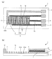
- FIG. 1 is a schematic plan view showing an example of an endotoxin detection chip of the present invention and a schematic cross-sectional view taken along the line AA.
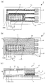
- FIG. FIG. 4 is a schematic plan view showing another example of the endotoxin detection chip of the present invention and a schematic cross-sectional view taken along the line CC.
- FIG. 2 is a cyclic voltammogram of evaluation 1 in Example 1.
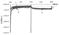
- FIG. 3 is an amperogram of evaluation 2 in Example 1.
- 4 is an amperogram of evaluation 3 in Example 1.
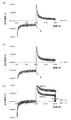
- 4 is an amperogram of evaluations 5 and 6 in Example 2.
- FIG. 4 is a graph showing the relationship between time (minutes) and reaction current (nA) in Example 2.
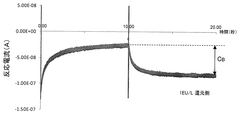
- 10 is an amperogram of evaluation 8 in Example 3.
- 10 is an amperogram of evaluation 9 in Example 3.
- the endotoxin detection chip of the present invention comprises a support base material, an electrode portion formed on the support base material and having two working electrodes, and formed on the support base material.
- An endotoxin detection chip having at least connected terminal portions, wherein the two working electrodes are alternating comb-shaped electrodes, and the amplification factor upon induction of a redox cycle is 5 times or more It is.
- FIG. 1 is a schematic plan view showing an example of the endotoxin detection chip of the present invention and a schematic cross-sectional view taken along the line AA.
- an endotoxin detection chip 1 is formed on a support base 2 and the support base 2, and has an electrode portion having two working electrodes 3 and a counter electrode 4. 6 and a terminal portion 8 formed on the support base material 2 and connected to the electrode portion 6, the two working electrodes 3 are alternating comb electrodes, and at the time of redox cycle induction The amplification factor is 5 times or more.
- the amplification factor at the time of inducing the redox cycle is 5 times or more, for example, it is possible to stably detect the current value output from 1 EU / L endotoxin.
- the current value output as noise that is, the current value output when measuring a sample with an endotoxin concentration of 0 EU / L
- the current value output from an endotoxin of 1 EU / L can be distinguished stably.
- an endotoxin detection chip having only one working electrode that is, when the amplification factor is 1 time, as described above, it is output when a sample having an endotoxin concentration of 0 EU / L is measured.
- the current value (noise) is 25 nA
- the current value output from endotoxin having an endotoxin concentration of 1 EU / L is about 10 nA, which may be less than half of the noise.
- the current value due to noise is proportional to the area of the working electrode
- the current value output from endotoxin is proportional to the area of the working electrode and the amplification factor.
- the reference sample can detect a current value of approximately 25 nA as noise
- the measurement sample 1 can detect a current value of approximately 50 nA as an output current derived from endotoxin.
- the endotoxin detection chip in which the amplification factor of the two working electrodes is 5 times has an upper limit of the current value detected as noise and a current value detected from a sample having an endotoxin concentration of 1 EU / L. The lower limit is not stably overlapped.
- the endotoxin detection chip of the present invention has a current value output as noise and a current output derived from, for example, 1 EU / L endotoxin. It is possible to stably distinguish the value from the current value, and it is possible to prevent the current value derived from endotoxin from being buried in the noise.
- the present invention does not simply increase the amplification factor to amplify the current value detected from endotoxin, but in the vicinity of 1 EU / L, which has recently been required in the medical field. In the detection of endotoxin, the purpose is to eliminate the influence of noise that has been revealed for the first time.
- FIG. 2 is a schematic plan view showing another example of the endotoxin detection chip of the present invention and a schematic cross-sectional view taken along the line CC.
- the endotoxin detection chip 1 of the present invention exposes at least the insulating layer 9 formed so as to cover the conductor portion 7, and at least the terminal portion 8, And an accommodating portion 15 formed by the second base material 10 disposed so that the opening is positioned on the electrode portion 6.
- the endotoxin detection chip 1 of the present invention shows an example in which the measurement region M is included in the storage unit 15, and the storage unit and the measurement region are the same in plan view.
- FIG. 2A omits the description of the second base material 10 for ease of explanation.
- the endotoxin detection chip of the present invention has the above-described housing portion, so that the subject can be stably held in the measurement region, and can be stably subjected to an electrochemical reaction with respect to the subject.
- the current value can be measured.
- FIG. 3 is a schematic plan view showing another example of the endotoxin detection chip of the present invention and a schematic cross-sectional view taken along the line DD.
- the endotoxin detection chip 1 of the present invention includes an insulating layer 9 formed so as to cover the conductor portion 7 and the connecting portion 3b, and at least a terminal portion 8. And an accommodating portion 15 formed by the second base material 10 which is exposed and disposed so that the opening is positioned on the electrode portion 6.
- the endotoxin detection chip 1 of the present invention shows an example in which the measurement region M is included in the storage unit 15, and the storage unit 15 and the measurement region M are the same in plan view.
- the endotoxin detection chip 1 of the present invention has a lid 12 and an inlet 13 formed in the lid 12.
- the endotoxin detection chip of the present invention is coated with a reagent containing a factor C and a peptide compound to which a redox substance is bound in the measurement region where the comb teeth are arranged.
- the measurement of the current value can be started immediately after the formation of the mixture after the reaction.
- the endotoxin detection chip of the present invention can prevent contamination of endotoxin and the like in the air by having the lid portion, and further from the analyte, the pre-reaction mixture, the post-reaction mixture, and the like. The volatilization of the solvent can be prevented.
- the two working electrodes in the present invention have an amplification factor that allows the current value output from the endotoxin concentration to be larger than the current value output as noise.
- Redox cycling The amplification factor during induction is 5 times or more.
- the amplification factor during induction of redox cycling is the ratio of the limiting current value (current value at measurement) when redox cycling is induced to the limiting current value (reference current value) when redox cycling is not induced (current value at measurement) / Reference current value).
- a pAP aqueous solution in which p-aminophenol (pAP) is dissolved in a 0.1 M KCl aqueous solution to make the pAP concentration 0.5 mM is prepared.
- this pAP aqueous solution is dropped so as to cover all the exposed portions of the two working electrodes in plan view, and only one working electrode has a potential scanning speed of 100 mV / s and a potential (0V ⁇ 0.6V ⁇
- the current value at 0.6V obtained from the single-mode cyclic voltammogram measured by scanning -0.2V ⁇ 0V) is used as the reference current value, and the reduction potential is fixed to 0V and applied to the other working electrode. Obtained from a dual-mode cyclic voltammogram measured by scanning the potential (0V ⁇ 0.6V ⁇ ⁇ 0.2V ⁇ 0V) at one working electrode at a potential scanning speed of 100 mV / s.
- a current value of 0.6V in one of the working electrode is an electrode of scanning potential.
- 4 (a) and 4 (b) show examples of a single mode cyclic voltammogram and a dual mode cyclic voltammogram when pAP is used as the redox material, respectively. May be indicated by A2 / A1 in FIG.
- the amplification factor is calculated as 16.69 ⁇ A / 1.241 ⁇ A ⁇ 13.4.
- the amplification factor in the present invention is not limited as long as the current value output from the endotoxin concentration can be larger than the current value output as noise, and more specifically, 1 EU /
- the L endotoxin can be stably detected.
- Such an amplification factor can be, for example, 5 times or more, and in the present invention, it is preferably in the range of 5 to 20 times, particularly in the range of 5 to 15 times. It is preferable that This is because, when the amplification factor is within the above-described range, for example, the endotoxin detection chip of the present invention can stably detect 1 EU / L endotoxin.
- the endotoxin detection chip of the present invention can easily form a comb-shaped electrode as a working electrode, for example, and can be easily reduced in size. Because it becomes possible.
- reaction current value when the concentration of endotoxin using the subject sample is 0EU / L and C A
- reaction current value when the concentration of endotoxin using the subject sample is 1 EU / L the when the C B
- the value of C B / C A is, for example, 1.2 or more, may be 1.5 or more, may be two or more.
- the reaction current values C A and C B are usually current values obtained from the same conditions, and the method for obtaining the reaction current values is not particularly limited.
- a Pd electrode is used as a working electrode
- a LAL reagent is used as a reagent
- an oxidation potential side current obtained by measurement by an amperometry method is measured immediately after the pulse application.
- the difference from the current value is preferably used as the reaction current value.
- Electrode part The electrode part in this invention is formed on a support base material, and has two working electrodes. Moreover, in this invention, as shown in FIG. 1, the electrode part may have a counter electrode and a reference electrode. Hereinafter, each structure of the electrode part in this invention is demonstrated in detail.
- the working electrode in the present invention includes two working electrodes.
- the working electrode is generally an electrode for performing electrochemical measurement by causing an electrochemical reaction of a target object.
- the two working electrodes are alternating comb electrodes.
- the alternating comb-shaped electrodes are two comb-shaped electrodes arranged so that the comb-tooth portions are adjacent in the width direction, that is, the comb-tooth portions are meshed with each other. Since the two working electrodes are such alternating comb-shaped electrodes, it becomes easy to arrange a wide area portion of the two working electrodes in the same plane within a limited area within a distance close to each other. .
- the working electrode is oxidized or reduced by the oxidation or reduction reaction generated at one working electrode. Since the distance traveled to the other working electrode is shortened, the number of cycles in redox cycling in which the redox substance moved to the other working electrode is reduced or oxidized can be increased, and loss can be reduced. . Therefore, the working electrode can easily adjust the amplification factor.
- the working electrode can efficiently amplify the detected current value.
- the area of the working electrode in plan view may be any as long as it can obtain a current value that can be detected by the measuring device.
- the area is, for example, an area where the current value of noise is 10 nA or more, more specifically, 180 ⁇ L of the buffer solution attached to the LAL reagent (Endspace ES-24M), 200 ⁇ L of the attached distilled water, 10 mM LGR-pAP was added dropwise so as to cover all of the two working electrodes, and the potential (0V ⁇ 0.6V ⁇ ⁇ 0.2V ⁇ 0V) was applied to only one working electrode at a potential scanning speed of 100 mV / s.
- the area at which the current value at 0.6 V obtained from a single-mode cyclic voltammogram measured by scanning is 10 nA or more can be obtained. More specifically, the area can be 2 mm 2 or more, and is preferably in the range of 2 mm 2 to 50 mm 2 , particularly in the range of 4 mm 2 to 10 mm 2. preferable. Since the area is within the above range, the endotoxin detection chip of the present invention stably stabilizes the current value output as noise and the current value output from, for example, 1 EU / L endotoxin. This is because it is possible to distinguish between the two, and the size can be easily reduced.
- the area in the plan view of the working electrode refers to the area of the exposed portion of the working electrode that can come into contact with the post-reaction mixture or the like in the plan view. Therefore, for example, as shown in FIG. 1A described above, when all of the working electrodes are exposed, the area is equal to two comb-shaped electrodes indicated by the shaded portion A shown in FIG. It can be set as the total planar view area. Further, as shown in FIG. 2A, when only a part of the working electrode is exposed, such as when the working electrode is arranged in the housing portion, the area is shaded as shown in FIG. The total area of the exposed regions of the comb-shaped electrode indicated by the part A can be set as a planar view area.
- FIG. 5B shows an example in which only the comb-teeth portion is exposed in the comb-shaped electrode, that is, an example in which the area is the sum of the areas of the comb-teeth in a plan view.
- the space between the comb tooth portions of the two comb electrodes is not limited as long as the two comb electrodes have a desired amplification factor.
- the amplification factor is five times or more. In view of the above, it can be in the range of 1 ⁇ m to 15 ⁇ m, and in particular, it is preferably in the range of 3 ⁇ m to 10 ⁇ m, particularly preferably in the range of 3 ⁇ m to 9 ⁇ m. This is because, when the space is within such a range, the comb electrode can easily have a desired amplification factor.
- the space between the comb-tooth parts of the two comb-shaped electrodes refers to S in FIG.
- Examples of other shapes of the comb-shaped electrode include the width, length, and number of the comb-tooth portions, the width between the adjacent comb-tooth portions, and the width of the connecting portion. Any shape can be used as long as it can accurately form a comb-shaped electrode having a desired amplification factor.
- the width and length of the comb teeth, the width between adjacent comb teeth, and the width of the connecting portion are indicated by a, b, c and d in FIG. Is.
- FIG. 1A already described shows an example in which the number of comb teeth per comb electrode is four.
- the width of the comb tooth portion (a in FIG.
- 1 (a)) is not particularly limited as long as it can be used as a chip for detecting endotoxin with desired accuracy, but it is in the range of 1 ⁇ m to 10 ⁇ m. In particular, it is preferably in the range of 3 ⁇ m to 9 ⁇ m.
- the length of the comb tooth portion (b in FIG. 1 (a)) can be in the range of 50 ⁇ m to 10,000 ⁇ m, and in the present invention, in particular, in the range of 80 ⁇ m to 10,000 ⁇ m, In particular, it is preferably in the range of 100 ⁇ m to 10,000 ⁇ m.
- the number of comb teeth can be in the range of 50 to 300 per comb electrode.
- the width between adjacent comb teeth in one comb electrode can be in the range of 3 ⁇ m to 30 ⁇ m.
- the width of the connecting portion (d in FIG. 1A) can be in the range of 50 ⁇ m to 10,000 ⁇ m.
- the thickness of the working electrode (e in FIG. 1B) is preferably in the range of 10 nm to 150 nm, more preferably in the range of 30 nm to 100 nm, and particularly preferably in the range of 30 nm to 50 nm.
- the material and the manufacturing method of the working electrode can be the same as those of an electrode portion of a general biosensor described later.
- the counter electrode in the present invention is an electrode for compensating for excess and deficiency of electrons in the solution caused by reaction at the working electrode and maintaining electrical neutrality. That is, the counter electrode is used to prevent the reaction on the working electrode from being delayed because the electrical neutrality is maintained.
- the form of the counter electrode can be the same as that generally used for the electrode part of the biosensor.
- the counter electrode material and the manufacturing method can be the same as those of an electrode section of a general biosensor described later.
- the reference electrode is generally an electrode that serves as a reference when determining the potential of the working electrode.
- the reference electrode serves as a reference for determining the potentials of the two working electrodes.
- the planar view shape of the reference electrode can be the same as that generally used for the electrode part of the biosensor.
- the material and manufacturing method of the reference electrode can be the same as those of an electrode portion of a general biosensor described later.
- the material of the electrode part is not particularly limited as long as it has desired conductivity.
- a noble metal material having non-corrosive properties hereinafter simply referred to as a noble metal material.
- other metal materials other than the noble metal materials can be used.
- the material is not limited to a metal material, and conductive carbon, conductive particles dispersed in a cured binder resin, or the like can also be used.
- noble metal materials include gold (Au), platinum (Pt), palladium (Pd), rhodium (Rh), iridium (Ir), ruthenium (Ru), and osmium (Os). Since these noble metal materials have a low ionization tendency and are electrochemically stable, they are not easily corroded by moisture, hydrogen peroxide, etc., and have high conductivity. It is suitable as.
- the material of the two working electrodes is preferably Pd.
- the other metal material may be anything other than the noble metal material.
- copper (Cu), iron (Fe), cobalt (Co), aluminum (Al), chromium (Cr), nickel (Ni) Metals such as titanium (Ti), cerium (Ce), tantalum (Ta), tin (Sn), alloys containing the above metals such as stainless steel (SUS), metal compounds such as indium tin oxide (ITO), etc.
- nickel is preferable from the viewpoint of corrosion resistance.
- the material preferably used is, for example, preferably gold, platinum, or conductive carbon for the working electrode and the counter electrode, and preferably palladium for the reference electrode. This is because these materials are excellent in corrosion resistance and conductivity.
- the method for forming the electrode part is not particularly limited as long as the electrode part can be formed in a desired pattern on a support base material. Examples include a method of patterning the conductive film by photolithography after preparing a support substrate and forming a conductive film on the entire surface, a mask vapor deposition method, a screen printing method, a gravure printing method, a flexographic printing method, an inkjet method, and the like. .
- Terminal part The terminal part in this invention is connected with the said electrode part, and is for connecting with the measuring apparatus which quantifies an endotoxin density
- the material of the terminal part can be the same as the material of the electrode part.
- the material of the terminal portion only needs to ensure conductivity that does not affect the detection current value and the applied voltage, and a general conductive material can be used.
- Au from the viewpoint of conductivity, Au, A noble metal such as Ag, Pt or Pd and a metal such as Cu or Ni are preferred.
- the terminal portion preferably has a low contact resistance and has a strength that does not peel off when brought into contact with the connector.
- a desired conductive material is formed by forming a thin film of a conductive material and laminating conductive carbon. And a terminal portion with low contact resistance can be formed.
- the method for forming the terminal portion can be the same as the method for forming the electrode portion.
- the terminal portion may be formed simultaneously with the electrode portion or may be formed separately from the electrode portion.
- the measurement device a device generally used for electrochemical measurement can be used, and examples thereof include a potentiostat, a current amplifier, and a device having the same function as these.
- the measuring device according to the present invention preferably has a current value output as noise of less than 40 nA, and particularly preferably within a range of 5 nA to 30 nA. This is because the endotoxin detection chip of the present invention can exhibit the effect that, for example, 1 EU / L endotoxin can be stably detected by using the measurement apparatus.
- the noise described above covers, for example, 180 ⁇ L of the buffer solution attached to the LAL reagent (Endspace ES-24M), 200 ⁇ L of the attached distilled water, and 20 ⁇ L of 10 mM LGR-pAP covering all the two working electrodes. Obtained from a single-mode cyclic voltammogram measured by scanning the potential (0V ⁇ 0.6V ⁇ ⁇ 0.2V ⁇ 0V) at a potential scanning speed of 100 mV / s on only one working electrode. Current value at 0.6V. Moreover, the current value output as the noise can be a current value detected when the area of the working electrode is 2 mm 2 , for example.
- Support base material The support base material used for this invention supports an electrode part and a terminal part, and the surface in which the said electrode part and a terminal part are formed has insulation.
- the support substrate for example, a resin substrate, paper, a ceramic substrate, a glass substrate, a semiconductor substrate having at least a surface insulation, a metal substrate, or the like can be used.
- the support base material may have rigidity or may have elasticity. Among them, it is preferable to have electrical insulation and elasticity, and for example, a film such as polyethylene terephthalate (PET) resin, vinyl chloride resin, polystyrene (PS) resin, polypropylene (PP) resin can be suitably used.
- PET polyethylene terephthalate
- PS polystyrene
- PP polypropylene
- the support base material may have flexibility and does not need to have it. Further, it does not matter whether the supporting substrate is transparent.
- the supporting base surface may be treated or modified.
- treatment and modification of the surface of the supporting substrate include corona treatment, UV treatment, antifogging treatment, and modification by coding a material having a sulfonic acid group or a sulfuric acid group.
- the shape, size, thickness, and the like of the support substrate can be appropriately set depending on the shape of the connecting portion of the measuring instrument that uses the endotoxin detection chip of the present invention.
- the support substrate may be long or single-wafer.
- the electrode part, the wiring part, and the terminal part can be continuously formed by a roll-to-roll method.
- the endotoxin detection chip of the present invention has at least a support base, the electrode part formed on the support base, and the terminal part. It may have.
- the accommodating part which can accommodate a test object fixed amount
- the 2nd base material provided in order to form an accommodating part
- the conducting wire part which electrically connects the said electrode part and the said terminal part
- an insulating layer that covers the conductor portion and the connecting portion can be used.
- the endotoxin detection chip of the present invention preferably has a storage unit that can store a subject, and the electrode unit is disposed inside the storage unit.
- the endotoxin detection chip can stably hold the analyte in the measurement region, and can stably maintain a current value due to an electrochemical reaction with respect to the analyte. This is because measurement is possible.
- a housing part it may be formed by a groove of the support base material, and an insulating material such as a second base material in which a groove or an opening corresponding to the support base material and the housing part is formed.
- the insulating member may include an insulating layer described later. That is, the housing portion can be a region surrounded by the second base material, the insulating layer, and the like.
- the constituent material of the second base material may be a material different from the support base material or the same material. 2 to 3 that have already been described, the housing portion 15 is formed by laminating the support base material 2, the second base material 10 in which an opening corresponding to the housing portion 15 is formed, and the insulating layer 9. The example formed by this is shown.
- the shape of the accommodating portion is not particularly limited, and examples of the shape of the accommodating portion in plan view include a circle, an ellipse, and a rectangle.
- the cross-sectional shape of the housing portion can be, for example, a semicircular shape, a rectangular shape, or the like.
- the capacity of the housing portion is preferably in a range of 1 mm 3 ⁇ 200 mm 3, among them 1 mm 3 in the range of ⁇ 100 mm 3, and particularly preferably in the range of 1mm 3 ⁇ 50mm 3.
- the size of the accommodating portion may be, for example, about 1 mm to 5 mm in diameter and about 1 mm to 10 mm in depth when the shape of the accommodating portion is a circular shape.
- the location for forming the accommodating portion is not particularly limited as long as the subject can be accommodated and the electrode portion can be disposed therein.
- the formation location of the housing portion is the same as the measurement region in plan view, and the measurement region is defined by the housing portion, and the formation location of the storage portion in the plan view is the measurement region. A broader range can be included. The measurement area will be described later.
- it is particularly preferable that the location where the housing portion is formed is the same as the measurement region. This is because the mixture after the reaction of the analyte can be stably brought into contact with the electrode portion.
- the method of introducing the analyte is a method of dropping from above the container, the analyte can be easily introduced into the measurement region to form the post-reaction mixture, and the post-reaction mixture This is because can be stably brought into contact with the electrode part.
- 2 and 3 described above show an example in which the housing portion 15 includes the electrode portion 6 (working electrode 3, counter electrode 4 and reference electrode 5) in plan view. An example in which the location is the same as the measurement region M in plan view is shown.
- the constituent material constituting the housing part is not particularly limited as long as it can stably form the housing part and does not inhibit the liberation reaction, inorganic materials such as silicon and glass, acrylic resin, Examples thereof include silicone resins such as polydimethylsiloxane (PDMS) and resin materials such as epoxy resins.
- the constituent material may be a single material or a combination of two or more materials.
- the method for forming the housing part is not particularly limited as long as it can stably form the housing part having a desired shape, and can be appropriately selected depending on the constituent material of the housing part.
- the forming method includes a concave portion used as the housing portion or the like using anisotropic dry etching, wet etching using hydrofluoric acid, or the like. The method of forming can be mentioned.
- the constituent material is a silicone resin or the like
- a photoresist formed in an inverted shape corresponding to the accommodating portion or the like on a silicon wafer using a normal photolithography method is used as a mold.
- the cured silicone resin is peeled off from the mold, and thus the above-mentioned accommodating portion and the like
- the method of forming the recessed part used as can be mentioned.
- the constituent material is a resin material
- the resin material is pressed by pressing a mold in which concave and convex shapes corresponding to the housing portion are formed, and the resin material is cured by irradiation with ultraviolet rays or heating.
- a method of forming a concave portion used as the housing portion or the like by peeling the cured product of the resin material from the mold can be exemplified.
- the forming method may be a method of forming a recess in the constituent material using a laser or the like.
- the forming method includes preparing two substrates on which recesses corresponding to the housing portions are formed, and bonding them so that the recesses of the two substrates face each other, and an opening as the recess.
- a method of bonding a single formed substrate and a flat substrate may be used.
- the 2nd base material may be arrange
- a 2nd base material is provided in order to form the said accommodating part.
- the second base material can have an opening corresponding to the accommodating portion. The size and shape of the opening can be the same as the size and shape of the housing.
- the second base material if it has insulation, it will not specifically limit, For example, a resin base material etc. are mentioned.
- the shape of the second base material is not particularly limited, and may be any shape such as a square, a rectangle, a circle, an ellipse, or the like.
- the second base is disposed on the support base so that at least the terminals are exposed and the opening of the second base is located on the electrode.
- the said 2nd base material can be affixed on a support base material through an adhesive agent or an adhesive, for example.
- the endotoxin detection chip of the present invention may include a lid that covers the upper surface of the housing. Mixing of endotoxin and the like in the air can be prevented, and further, volatilization of the solvent from the analyte, the pre-reaction mixture, the post-reaction mixture, and the like can be prevented. Therefore, the endotoxin detection chip of the present invention can detect the endotoxin concentration with high accuracy.
- FIG. 3 described above shows an example in which the endotoxin detection chip 1 has the lid portion 12, and the lid portion 12 is supported by the second base material 10 with respect to the support base material 2. The example formed is shown.
- the shape of the lid portion may be any shape as long as it can cover the upper surface of the endotoxin detection chip, and may be a plate shape. Note that FIG. 3 already described shows an example in which the lid 12 has a plate shape. Further, when the endotoxin detection chip has a structure in which two base materials in which concave portions corresponding to the housing portions and the like are formed are bonded so that the concave portions face each other, one base material Can be used as the lid.
- the lid portion may have a through hole.
- the through hole can be used as an inlet for the subject. Since the introduction port will be described later, description thereof is omitted here. Note that FIG. 3 already described shows an example in which the lid portion 12 has the introduction port 13.
- the lid may be recloseable. By closing the lid and introducing the subject into the container and then closing it again, contamination of endotoxin in the air can be prevented, and the endotoxin detection chip can be used to detect the endotoxin concentration. It is because it can be made excellent.
- the endotoxin detection chip of the present invention may have an inlet for introducing the subject into the lid.
- the size of the introduction port may be any size as long as the subject can be introduced, and may be the same as the size of the container in plan view.
- the shape of the introduction port is not particularly limited, but the shape of the introduction port in plan view is preferably circular or elliptical because it is easy to form the introduction port.
- the introduction port may be covered with a reclosable film or the like. Since it is the same as the reason described in the section “(3) Lid”, the description is omitted here.
- a reclosable adhesive layer is preferably formed at the end of the film, and can be the same as a normal reclosable film.
- the endotoxin detection chip of the present invention usually has a conductive wire portion that electrically connects the electrode portion and the terminal portion.
- the material of the conducting wire part can be the same as the material of the electrode part.
- As the material of the conductive wire portion it is only necessary to ensure conductivity that does not affect the detected current value, and a general conductive material can be used. Among them, from the viewpoint of conductivity, Au, Ag, Pt It is preferable that there are noble metals such as Pd and metals such as Cu and Ni.
- the method for forming the conductor portion can be the same as the method for forming the electrode portion.
- the said conducting wire part may be formed simultaneously with an electrode part, and may be formed separately from an electrode part.
- the endotoxin detection chip of the present invention may have an insulating layer so as to cover at least the conductor portion. This is because the endotoxin detection chip of the present invention can suppress oxidation of the conductor portion and the like by the insulating layer.
- a material for the insulating layer for example, a thermosetting resin, a photocurable resin, or the like can be used.
- the insulating layer may be formed by any method as long as it can form the insulating layer in a pattern so as to cover at least the conductor portion and not the electrode portion and the terminal portion. For example, a photolithography method or a screen printing method may be used. , Gravure printing method, flexographic printing method, inkjet method and the like.
- the said insulating layer may be used also as the above-mentioned 2nd base material, for example.
- the endotoxin detection chip of the present invention has a factor C and a redox substance bound in the measurement region where the comb teeth of the comb electrode used as a working electrode are arranged. It is preferable that a reagent containing a peptide compound is immobilized. Furthermore, as illustrated in FIG. 3, the endotoxin detection chip of the present invention may have a housing portion so as to include the measurement region, and the reagent may be immobilized in the measurement region.
- the measurement region is a region where the electrode part is arranged and a current value is measured by an electrochemical reaction.
- the immobilization in the region is not limited to the one formed so as to cover the entire surface of the measurement region in a plan view, but is usually limited to one in the measurement region in a plan view. It is formed in the area of the part. Since the reagent is immobilized in the measurement region in which the comb tooth portion is arranged, after the reaction, which is a target for measuring the current value in the electrochemical reaction, only by introducing the analyte into the endotoxin detection chip. Thus, it is possible to obtain a mixture of the analyte, the factor C and the peptide compound after the completion of the free reaction.
- the post-reaction mixture is taken out of the container and introduced into the endotoxin detection chip.
- the process to perform can be made unnecessary.
- the endotoxin detection chip can stably detect, for example, 1 EU / L endotoxin.
- the reagent is immobilized means that the mixture of the components of the reagent is disposed in a dry state.
- the endotoxin detection chip is, for example, 1 EU / L endotoxin can be detected stably.
- FIG. 6 and FIG. 7 are schematic diagrams showing an example of the case where the liberation reaction is a multistage reaction, in which the redox substance is paramethoxyaniline (hereinafter sometimes simply referred to as pMA) and paraamino.
- pMA paramethoxyaniline
- phenol hereinafter sometimes referred to as a unit pAP
- an active factor C is converted from factor C
- an active factor B is converted from factor B by allowing an analyte containing endotoxin to act on factor C.
- activated coagulase is generated one after another from the coagulase precursor, and pMA and pAP are released from the peptide compound to which pMA is bound and the peptide compound to which pAP is bound by the activated coagulase, respectively.
- Endotoxin is quantified with respect to the said mixture after the said free reaction based on the electric current value measured by an electrochemical reaction. That is, pMA or pAP released from the peptide compound exists in the mixture after the release reaction, and pMA or pAP undergoes an oxidation reaction at a specific potential.
- the electrode potential is equal to or higher than the oxidation potential, for example, in the case of pMA, electrons are emitted according to the scheme of the following formula (1) and oxidized, and in the case of pAP, the following formula (2) According to the scheme, electrons are emitted and oxidized.
- the current value measured by the electrochemical reaction is proportional to the concentration of pMA or pAP. Since there is a correlation between the concentration of endotoxin and the progress of the multistage reaction, there is also a correlation between the concentration of endotoxin and the concentration of pMA or pAP generated, that is, the current value. Therefore, the endotoxin concentration can be measured from the current value by preparing in advance a calibration curve showing the correlation between the endotoxin concentration and the current value.
- the endotoxin concentration detection using an electrochemical reaction makes it possible to detect the reaction on the electrode surface, and the endotoxin concentration can be measured even with a small amount of sample. Therefore, the above-mentioned endotoxin detection chip not only enables stable detection of, for example, 1 EU / L endotoxin, even in a very small amount of analyte, but also enables rapid detection. Furthermore, the use of a so-called lysate reagent containing factor B and a coagulation enzyme precursor in factor C, or an expensive enzyme such as factor C can be greatly reduced, and the endotoxin detection chip has, for example, 1 EU / L. Endotoxin can be detected stably.
- the endotoxin concentration detection method using an electrochemical reaction is not a detection method using light unlike the colorimetric method, so low-transparency analytes and multi-component analytes such as tissue fluids are also subject to measurement. It is thought that it can be done and is extremely practical.
- endotoxin can be quantified easily, quickly and with high accuracy at a medical site, and strict mixing prevention management of endotoxin can be performed on pharmaceuticals and medical instruments that are in direct contact with blood. .
- each configuration of the reagent, the immobilization position, and the release reaction will be described in detail.
- the reagent used for this invention contains the peptide compound which C factor and the redox substance couple
- the reagent may contain a buffer component. This is because the endotoxin detection chip of the present invention can detect the endotoxin concentration of the subject in a short time because the reaction rate of the above-described free reaction can be improved.
- the reagent contains the buffer component, it contains a peptide compound to which factor C and a redox substance are bound, and a buffer solution is added separately using a conventional reagent that does not contain the buffer component.
- the reaction rate can be improved as compared with the result of the release reaction, the factor C and the peptide that contact the analyte when the analyte contacts the reagent. It can be inferred that the concentration of the compound and the buffer component can be increased.
- the reagent is immobilized in the measurement region where the comb teeth are arranged.
- the above-mentioned factor C is particularly limited as long as it can generate an active factor C by endotoxin and further cause a free reaction to liberate the redox substance from the peptide compound by the active factor C. is not.
- factor C isolated and purified from a biological component such as a blood cell extract component of horseshoe crab, a recombinant factor C produced by a gene recombination technique, and the like can be used as appropriate.
- the above-mentioned factor C is used together with factor B and a clotting enzyme precursor, that is, the reagent contains a multistage reaction composition containing factor C, factor B and a clotting enzyme precursor.
- the composition for multistage reaction is not particularly limited as long as it contains factor C, factor B and a coagulation enzyme precursor.
- factor C factor C
- factor B factor B
- a coagulation enzyme precursor for example, it is based on a blood cell extract component of horseshoe crab called Limulus Ambocyte Lysate (LAL).
- LAL Limulus Ambocyte Lysate
- the prepared lysate reagent can be used.
- C-factor, B-factor and coagulase precursor such as those prepared by combining factor C, factor B and coagulase precursor isolated and purified from biological components such as blood cell extract components of horseshoe crab
- lysate reagents also include those prepared by combining those isolated and purified from biologically derived components such as blood cell extract components of horseshoe crab. Such a lysate reagent can be used as “LAL equivalent”.
- a composition prepared by appropriately using recombinant factor C, recombinant factor B, or a recombinant coagulase precursor prepared by a gene recombination technique is used as an “LAL equivalent”.
- LAL and LAL equivalents may be referred to as LAL reagents.
- the content of the factor C or the multistage reaction composition in the reagent is not particularly limited as long as the concentration of endotoxin can be accurately detected, and the analyte in the endotoxin detection chip of the present invention Is appropriately set according to the introduction amount of the container, the presence / absence of the accommodating portion, the volume of the accommodating portion and the like.
- content in the said reagent of the said multistage reaction composition it can be made into the same quantity as the lysate reagent for 1 test marketed for the endotoxin measurement used for an electrochemical method, for example.
- the peptide compound to which the redox substance is bonded is only required to have a redox substance and an oligopeptide compound to which the redox substance is bonded.
- the redox substance is bonded to one end of the oligopeptide compound.
- a peptide compound having a protecting group bonded to the other end can be used. Examples of such a peptide compound include those represented by XAY.
- X represents a protecting group
- A represents an oligopeptide compound
- Y represents the above redox substance.
- the protecting group X include protecting groups of peptide compounds such as t-butoxycarbonyl group (Boc), benzoyl group, acetate group and the like.
- the oligopeptide compound is not particularly limited as long as it can release a redox substance by the action of factor C or the multistage reaction composition.
- the oligopeptide compound preferably has 2 to 10 amino acids, particularly 2 to 5, more preferably 3 to 4.
- oligopeptides for factor C that can release redox substances by the action of factor C include, for example, Val-Pro-Arg, Asp-Pro-Arg, Leu-Gly-Arg, etc. as tripeptides for factor C. Can be mentioned.
- Examples of the tripeptide for a multistage reaction composition capable of releasing a redox substance by the action of the multistage reaction composition include Leu-Gly-Arg, Thr-Gly-Arg, and the like.
- Examples of the tripeptide for the multistage reaction composition include a tripeptide having an L-amino acid in the general formula: R 1 -Gly-Arg-Y.
- R 1 represents an N-blocked amino acid.
- Examples of the oligopeptide for the multistage reaction composition include the tetrapeptide A 1 -A 2 -A 3 -A 4 in the general formula: R 2 -A 1 -A 2 -A 3 -A 4 -Y Can do.
- R 2 represents hydrogen, an aromatic hydrocarbon or an acyl group blocking
- a 1 represents Ile
- a 2 is Glu or Asp
- a 3 represents Ala or Cys
- a 4 represents Arg.
- Peptide compounds for a multistage reaction composition in which a redox substance is bonded to one end of an oligopeptide and a protecting group for the peptide is bonded to the other end are specifically Boc-Leu-Gly-Arg-Y, acetate -Ile-Glu-Ala-Arg-Y and the like.
- the redox substance is not particularly limited as long as it can be released from the peptide compound by activated factor C or the activated coagulase and causes an oxidation reaction or a reduction reaction at a specific potential.
- Specific examples of the redox substance include compounds represented by the following general formula (3) including pMA and the like, dyes, paraaminophenol (pAP), and the like.
- Specific examples of the dye include 2,4-dinitroaniline (DNP), p-nitroaniline (pNA), 7-methoxycoumarin-4-acetic acid (MCA), dansyl dye, and the like. .
- R is —O—C n H 2n + 1 or —S—C n H 2n + 1 , and n is an integer from 1 to 4.
- the compound represented by the general formula (3) is preferably pMA.
- a peptide compound of an oligopeptide compound in which the shorter the alkyl chain of the compound represented by the general formula (3), the higher the water solubility, and the activated factor C or the activated coagulase is contained in the peptide compound. It becomes easier to recognize the sequence. For this reason, since the compound represented by the general formula (3) bonded to the oligopeptide compound as a redox substance is pMA, the peptide compound has increased reactivity with the activated factor C and the like. It is.
- the redox substance is preferably pMA or pAP.
- PMA and pAP released from the peptide compound and pMA and pAP bound to the peptide compound have different redox potentials, and the difference is relatively large. Therefore, the current derived from the oxidation reaction of pMA and pAP released from the peptide compound and the current derived from the oxidation reaction of pMA and pAP bound to the peptide compound can be easily separated and obtained. Therefore, by using a peptide compound to which pMA or pAP is bound, even if the concentration of pMA or pAP released from the peptide compound is extremely small, for example, 1 EU / L endotoxin can be stably detected. .
- the content of the peptide compound in the reagent is not particularly limited as long as, for example, 1 EU / L endotoxin can be stably detected.
- Introduction of the analyte in the endotoxin detection chip of the present invention It is appropriately set according to the amount, the presence / absence of the accommodating portion, the volume of the accommodating portion, and the like.
- the content can be an amount that falls within the range of 0.1 mM to 5.0 mM when the post-reaction mixture is formed.
- the volume of the post-reaction mixture can be approximately the same as the volume of the analyte, and can be in the range of several ⁇ L to several tens of ⁇ L.
- the total content of the factor C or the multistage reaction composition and the peptide compound to which the redox substance is bound is not particularly limited as long as the endotoxin concentration can be accurately detected.
- the amount of the analyte introduced in the endotoxin detection chip of the present invention, the presence / absence of the accommodating portion, the volume of the accommodating portion, etc. are appropriately set.
- the total content of the multistage reaction composition and the peptide compound can be, for example, in the range of 1 mg to 10 mg, and more preferably in the range of 1 mg to 4 mg. This is because the content of expensive enzymes and the like can be reduced, and the endotoxin detection chip of the present invention can be reduced in price.
- the buffer component is a solid content of the buffer solution remaining when water is removed from the buffer solution by drying, and any buffer solution having a desired buffer capacity can be generated by adding pure water.
- the buffer component is not particularly limited as long as it can generate a buffer solution capable of stably releasing the redox substance.
- pH 6.0 to 9.0, particularly pH 7.0 to 8. Preferably, it is a component of 5 buffer solutions. This is because the release amount of the redox substance can be increased.
- the buffer component include Tris-acetate buffer, Tris-HCl (Tris-HCl) buffer, phosphate buffer, and HEPES (4- (2-hydroxyethyl) -1-piperazine etheric acid) buffer.
- Components such as PIPES (Piperazine-1, 4-bis (2-ethanesulfonic acid) buffer) and the like.
- the content ratio of the buffer component in the reagent is not particularly limited as long as it can generate a buffer solution in a desired pH range, and the amount of analyte introduced in the endotoxin detection chip of the present invention It is set as appropriate according to the presence / absence of the accommodating portion and the volume of the accommodating portion.
- the content ratio can be set to an amount capable of generating each buffer solution when the post-reaction mixture is formed.
- the reagent preferably contains at least a peptide compound to which factor C and a redox substance are bound, and further contains factor B, a coagulation enzyme precursor, and a buffer solution component, and other components as necessary. May be included.
- the 2nd oxidation-reduction substance which can react with the oxidation-reduction substance liberated from the said peptide compound can be mentioned. This is because the endotoxin detection chip of the present invention can detect the endotoxin concentration more accurately by causing the second redox substance after reacting with the redox substance to undergo an oxidation-reduction reaction with an electrode. .
- the second redox material can be appropriately selected according to the redox material.
- the reagent may have a porous structure having a large number of pores and a surface area larger than a structure having no pores (non-porous structure) having the same volume, or a non-porous structure. Good. This is because, when the reagent fixed in the measurement region where the comb tooth portion is arranged has a porous structure, the reagent quickly dissolves in the subject. Moreover, when it is the said non-porous structure, it is because the drying method by normal temperature normal pressure which is mentioned later can be used as a drying method of the said reagent, and the said reagent can be formed with simple equipment.
- the reagent has a porous structure or a non-porous structure
- the immobilized reagent when it is cloudy, it has a porous structure and has transparency.
- there are a method of visually judging that the structure is non-porous and a method of confirming by observation with a scanning electron microscope (SEM).
- the reagent immobilization method is not particularly limited as long as it is a method capable of immobilizing the reagent in the measurement region in which the comb teeth are arranged.
- the reagent in the measurement region where the comb teeth are arranged is immobilized.
- a method of applying the reagent solution to the position and drying it can be used.
- the drying method is not particularly limited as long as it can remove water from the reagent solution, and a method of drying at normal temperature and atmospheric pressure, a vacuum drying method of drying under reduced pressure, and the like can be used. .
- the drying method is the vacuum drying method. This is because the reagent solution can be dried in a state in which contamination of endotoxin in the air is prevented by the drying method being the vacuum drying method. In addition, since drying at room temperature or less is possible in a short time, the cost is reduced, the risk of endotoxin contamination is reduced, and the factor C, factor B and coagulase precursor contained in the reagent are denatured and activated. This is because it is possible to suppress the formation of a structure that does not. Further, when the drying method is the vacuum drying method or the like, the reagent can have a porous structure. In the present invention, the vacuum drying method is particularly preferably a freeze drying method.
- the reagent can have a lower density porous structure, that is, a larger void volume and a larger surface area, and the reagent has an excellent dissolution rate in the analyte. is there.
- the drying method is a method of drying under atmospheric pressure, the cost required for drying and immobilizing the reagent solution at a desired position and range can be reduced.
- the reagent is immobilized in the measurement region.
- the reagent immobilization position may be a position within the measurement region where the reagent can be brought into contact with the sample to be introduced. Specifically, as shown by the reagent 11 in FIG. 3, it may be formed so as to cover all the comb teeth 3b of the two working electrodes 3, or a part of the comb teeth 3b may be covered. It may be formed as follows. When the analyte is introduced from the introduction port, the reagent may be immobilized immediately below the introduction port.
- region is an area
- the measurement region M preferably includes all the parts (for example, the comb-teeth part 3b of the comb-shaped electrode) involved in the measurement of the electrode part 6 (the working electrode 3, the counter electrode 4, the reference electrode 5 and the like). Specifically, it is preferably a minimum rectangle including an end portion of the portion related to the measurement (for example, the tip portion of the comb tooth portion 3b, the opposite surface facing the working electrode of the counter electrode and the reference electrode). This is because the endotoxin detection chip can be easily reduced in size, and the endotoxin concentration can be accurately detected.
- the reagent containing the buffer solution component together with the peptide compound to which the factor C and the redox substance are bound is immobilized in the measurement region in which the comb tooth portion is arranged. It is possible to obtain the post-reaction mixture, which is a current value measurement target by an electrochemical reaction, simply by introducing the analyte into the housing without adding. Therefore, for example, the endotoxin detection chip can stably detect 1 EU / L endotoxin.
- the endotoxin detection chip of the present invention can be used for, for example, detection of 1 EU / L endotoxin, but is not limited to 1 EU / L, and is used for detection of endotoxin near 1 EU / L. Can do.
- As the vicinity of 1 EU / L for example, it can be in the range of 0.5 EU / L to 5 EU / L, and in particular, it is preferably in the range of 0.5 EU / L to 3 EU / L. It is preferably within a range of 0.5 EU / L to 2 EU / L. This is because the endotoxin within the above-mentioned range as the vicinity of 1 EU / L can effectively exhibit the effect of the present invention that the endotoxin can be stably detected due to the above-described amplification factor.
- analytes measured by the endotoxin detection chip of the present invention include biological samples such as blood, saliva, sweat, urine, environmental test objects, foods, cosmetics, waste liquids, resins, and the like. it can.
- the subject include pharmaceuticals such as dialysate and injections, medical tools, and the like.
- the analyte is not limited to a liquid sample and can include a gas sample, but is usually a liquid sample. When the analyte is a solid, a liquid sample dissolved or dispersed in an appropriate solvent such as a buffer solution can be used as the analyte to be measured.
- Endotoxin concentration quantification method The endotoxin concentration quantification method of the present invention is characterized by using the aforementioned endotoxin detection chip.
- the endotoxin concentration can be accurately determined by using the endotoxin detection chip described above. Since the endotoxin detection chip in the present invention is the same as the contents described in the above-mentioned “A. Endotoxin detection chip”, description thereof is omitted here.
- the endotoxin concentration can be determined from the reaction current value.
- the endotoxin concentration is preferably quantified after the sample is introduced and held for a predetermined time.
- the holding time is, for example, 60 minutes or less, 50 minutes or less, or 40 minutes or less.
- the holding time is, for example, 30 minutes or longer, and may be 35 minutes or longer.
- the holding temperature is not particularly limited, but is preferably around 37 ° C.
- a reagent containing a peptide compound in which a factor C and a redox substance are bound is immobilized in a measurement region where a comb tooth portion of a comb-shaped electrode used as the working electrode is disposed.
- the material for the two working electrodes is Pd
- the reagent is an LAL reagent.
- the endotoxin concentration can be quantified by using, as the reaction current value, the difference between the current value immediately before the pulse application and the current value after the pulse application in the oxidation potential side current obtained by measurement by the amperometry method. preferable.
- the current value immediately before the pulse application becomes a negative value, and the value also changes depending on the endotoxin concentration.
- the current value after applying the pulse is the current value when the temporal variation of the current value is so small that it can be ignored in quantifying the endotoxin concentration. For example, it may be 10 seconds after pulse application, 20 seconds later, or 30 seconds later.
- the present invention is not limited to the above embodiment.
- the above-described embodiment is an exemplification, and the present invention has substantially the same configuration as the technical idea described in the claims of the present invention, and any device that exhibits the same function and effect is the present invention. It is included in the technical scope of the invention.
- Example 1 After forming a 50 nm-thick gold sputtered film on a PET substrate (Toray Co., Ltd., Lumirror 350H10) by sputtering, etching is performed by photolithography, and two working electrodes as shown in FIG. As a pattern, a gold layer having an alternating comb electrode, an electrode portion including one counter electrode and one standard electrode, a terminal portion, and a wiring portion was formed to obtain an endotoxin detection chip. Further, an Ag / AgCl layer was formed on the gold layer of the standard electrode by a screen printing method. Thus, an endotoxin detection chip was obtained.
- the two comb-shaped electrodes constituting the alternating comb-shaped electrodes have two comb-shapes, with the width of the comb teeth (a in FIG. 1) and the width between the comb teeth (c in FIG. 1) being 9 ⁇ m and 27 ⁇ m, respectively.
- the space between the comb teeth of the electrode (S in FIG. 1) was 9 ⁇ m.
- the area of the two working electrodes was 4.5 mm 2 .
- sample solution 1 A pAP aqueous solution (sample solution 1) was prepared by dissolving p-aminophenol (pAP) in a 0.1 M KCl aqueous solution to a pAP concentration of 0.5 mM.
- the reference current value A1 and the measurement current value A2 obtained from the single-mode and dual-mode cyclic voltammograms were 1.44 ⁇ A and 7.36 ⁇ A, respectively, and the amplification factor (A2 / A1) was 5.1. It was twice.
- the result of the measured cyclic voltammogram of a single mode and a dual mode is shown to Fig.8 (a) and (b).
- CH1 represents the oxidation current at one working electrode on the side scanned with the potential (0V ⁇ 0.6V ⁇ ⁇ 0.2V ⁇ 0V)
- CH2 represents the voltage on the side where the potential is fixed. It shows the reduction current at the other working electrode.
- FIG. 8A and A2 in FIG. 8B are a reference current value and a measurement current value, respectively. Further, in FIG. 8, the horizontal axis represents voltage (V), and the vertical axis represents reaction current ( ⁇ A).
- V voltage
- ⁇ A reaction current
- Potentiostat CompactStat manufactured by Ivium Technologies was used as a measuring apparatus.
- sample solution 2 As a lysate reagent, 180 ⁇ L of buffer solution, 10 mM LGR-pAP is contained in one test tube of Endospecy ES24-M manufactured by Seikagaku Corporation, in which the lysate reagent is sealed in a dedicated test tube in a lyophilized state for each test. Was added and stirred. Next, 200 ⁇ L of distilled water (0 EU / L) was added and stirred to obtain a sample solution (sample solution 2). The peptide compound LGR-pAP used was Boc-Leu-Gly-Arg-pAP, which was dissolved in water for injection manufactured by Otsuka Pharmaceutical Co., Ltd. and stored at ⁇ 20 ° C.
- LGR-pAP was synthesized using the method described in JP-A-2015-187607.
- the buffer solution the buffer solution attached to Endospecy ES24-M manufactured by Seikagaku Corporation was used.
- FIG. 9 shows the results measured at the timing after the sample solution 2 was dropped and held at 37 ° C. for 60 minutes.
- Y1 indicates a reduction potential side current
- Y2 indicates an oxidation potential side current
- C1 fixes the reduction potential at -0.2V
- the oxidation potential is an initial potential of -0.2V.
- the output current value at the time of measurement which is the current value derived from the redox reaction of pAP when the potential is stepped (pulsed) to 0.4 V and then applied for 10 seconds after the voltage is applied for 10 seconds.
- the horizontal axis represents time (seconds), and the vertical axis represents reaction current (A).
- the reduction potential is fixed at ⁇ 0.2 V, and the initial potential of ⁇ 0.2 V is applied for 10 seconds, and then the potential is stepped (pulsed) to 0.4 V to 10
- the current derived from the redox reaction of pAP when applied for 2 seconds was recorded. Further, from FIG. 9, the measured output current value 10 seconds after the pulse application was 50 nA.
- Example 2 After forming a 50 nm thick Pd sputtered film on a PET substrate (Toray Industries, Lumirror 350H10) by sputtering, etching is performed by photolithography, and two working electrodes as shown in FIG. A pattern-shaped Pd layer having alternating comb-shaped electrodes, an electrode portion including one counter electrode and one standard electrode, a terminal portion, and a wiring portion was formed to obtain an endotoxin detection chip. Pd can be applied as a standard electrode, and it is not necessary to form an Ag / AgCl layer like an Au electrode.
- the two comb-shaped electrodes constituting the alternating comb-shaped electrodes have two comb-shapes, with the width of the comb teeth (a in FIG. 1) and the width between the comb teeth (c in FIG. 1) being 9 ⁇ m and 27 ⁇ m, respectively.
- the space between the comb teeth of the electrode (S in FIG. 1) was 9 ⁇ m.
- the areas of the two working electrodes was 4.5 mm 2.
- Sample solution 1 was obtained in the same manner as Example 1. Using the obtained sample solution 1, cyclic voltammogram measurement was performed in the same manner as in Example 1. As a result, the reference current value A1 and the measurement current value A2 obtained from the single-mode and dual-mode cyclic voltammograms were 1.4 ⁇ A and 7.5 ⁇ A, respectively, and the amplification factor (A2 / A1) was 5.3. It was twice.
- Endotoxin was mixed with distilled water (0 EU / L) to prepare a 1 EU / L endotoxin solution.
- a sample solution (sample solution 3, gene recombination type) was obtained in the same manner as in Evaluation 5, except that 200 ⁇ L of 1 EU / L endotoxin solution was used instead of 200 ⁇ L of distilled water (0EU / L).
- the obtained sample solution 3 was used to measure chronoamperometry characteristics.
- the measurement conditions are the same as in Evaluation 5.
- FIG. 11A and FIG. 11B are the results of evaluations 5 and 6 when the holding time is 35 minutes, respectively.
- FIGS. 11 (a) and 11 (b) when a ground current of 0 nA is used as a reference, the reaction current value 10 seconds after the pulse application is almost the same as in FIGS. 11 (a) and 11 (b). It was the same and the difference was small. This is because the endotoxin concentration is very low.
- the current value immediately before the pulse application (current value at the position indicated by X in the figure) is not 0 nA but a negative value, and the value is also the endotoxin concentration. It changed by.
- the difference in the reaction current value 10 seconds after the pulse application becomes large as shown in FIG. It was. Specifically, C A was 35 nA, C B was 63 nA, and C B / C A was 1.8.
- the method for defining the reaction current value is an application method in which the current value immediately before the pulse application changes depending on the endotoxin concentration.
- FIG. 11 shows the results when the holding time is 35 minutes, but the reaction current values were similarly defined when the holding time was 30 minutes and when the holding time was 40 minutes. The result is shown in FIG. As shown in FIG. 12, as the holding time increased, the value of C B / C A also increased, and at the time of holding time of 35 minutes, the value of C B / C A became 1.5 times or more.
- Example 3 In the same manner as in Example 1, an endotoxin detection chip was obtained.
- Sample solution 1 was obtained in the same manner as Example 2.
- the obtained sample solution 2 was used to measure chronoamperometry characteristics. After dripping the sample solution 2 so as to cover all the electrode parts of the endotoxin detection chip obtained in Example 3, the chronoamperometry characteristics were measured using the amperometry method, and the output current value at the time of measurement (reduction) The potential side current value) was measured. After the sample solution 2 was dropped, the measurement was performed at a timing after holding at 37 ° C. for 60 minutes.
- the pulse application conditions are the same as in Example 2.
Landscapes
- Life Sciences & Earth Sciences (AREA)
- Health & Medical Sciences (AREA)
- Chemical & Material Sciences (AREA)
- Molecular Biology (AREA)
- Immunology (AREA)
- Pathology (AREA)
- Engineering & Computer Science (AREA)
- Physics & Mathematics (AREA)
- Analytical Chemistry (AREA)
- Biochemistry (AREA)
- General Health & Medical Sciences (AREA)
- General Physics & Mathematics (AREA)
- Electrochemistry (AREA)
- Chemical Kinetics & Catalysis (AREA)
- Biomedical Technology (AREA)
- Hematology (AREA)
- Urology & Nephrology (AREA)
- Biotechnology (AREA)
- Cell Biology (AREA)
- Microbiology (AREA)
- Food Science & Technology (AREA)
- Medicinal Chemistry (AREA)
- Investigating Or Analyzing Materials By The Use Of Electric Means (AREA)
Abstract
本発明は、例えば、1EU/Lのエンドトキシンを安定的に検出可能なエンドトキシン検出用チップを提供することを主目的とする。 本発明は、支持基材と、上記支持基材上に成形され、2つの作用極を有する電極部と、上記支持基材上に形成され、上記電極部と接続された端子部と、を少なくとも有するエンドトキシン検出用チップであって、上記2つの作用極が、交互櫛形電極であり、レドックスサイクリング誘導時の増幅率が5倍以上であることを特徴とするエンドトキシン検出用チップを提供することにより、上記課題を解決する。
Description
本発明は、例えば、1EU/Lのエンドトキシンを安定的に検出可能なエンドトキシン検出用チップに関するものである。
エンドトキシンはグラム陰性菌の細胞壁に存在する物質であり、発熱性等の種々の生物活性を有している。そのため、例えば透析液、注射薬、移植組織片、人工授精の受精卵の培養溶液等の医薬品や医療用具がエンドトキシン等の微生物夾雑物で汚染された場合、極微量でも重篤な結果を招くことがあり、これらのエンドトキシン等の微生物夾雑物の汚染量は厳密に管理されなければならない。しかしながら、エンドトキシン等の微生物夾雑物は環境中に普遍的に存在し、さらに耐熱性を有するために加熱除去が困難であり、混入防止管理は非常に難しい。
エンドトキシンの検出試験には定性試験および定量試験があり、定性試験としてはゲル化法、定量試験としては比濁法、比色法、蛍光法が一般に知られている。いずれの方法においても、高精度の検出を行うには煩雑な手順や長時間を要する。
特に、近年、人工透析用の透析液については、透析液中のエンドトキシン活性値の透析液水質基準が1EU/L未満に規定され、迅速かつ高精度のエンドトキシン検出法が求められている。その理由は、新しい技術として血液透析ろ過療法(HDF療法)が開発され、透析液を血液に入れ、透析液で増加した分をろ過することにより、従来の透析技術では除去できなかった低分子タンパク質等の不要物を除去することが可能となったが、オンラインHDFでは補液として通常の透析液を大量に体内に入れるため、各透析施設での透析用水(RO水)および透析液の管理が非常に重要となったためである。したがって、1EU/Lのエンドトキシンを簡便かつ迅速に、高精度に測定することが非常に重要となっている。
現在、医療現場において実施されている、1EU/Lのエンドトキシンを検出できる方法としては、エンドトキシン標準溶液およびライセート試薬を使用した比色法を挙げることができるが、エンドトキシン試験用キットを使用したとしても操作が煩雑であるため、正確な測定には習熟が必要である。また、測定時間に少なくとも30分を要し、それ以上短縮することができないため、より簡便かつ迅速なエンドトキシン検出法が求められている。
さらに、上記比色法では、カブトガニの血球抽出成分から調製された試薬(ライセート試薬)が高価であるため、エンドトキシンの混入防止管理に必要な測定回数を実施することが難しい。
また、上記比色法では、545nmにおける吸光度を測定するため、透明性の低い被検体や、多成分を含む被検体を測定対象にできないという問題もある。
そこで、本発明者らは、高価なライセート試薬の使用量を減らすことができ、極微量のエンドトキシンしか含まれない被検体や、比色法では測定できない被検体に対して、比色法よりも安価に、かつ簡便にエンドトキシンの定量を可能とする電気化学反応によりエンドトキシンを検出するエンドトキシン検出方法およびそれに用いられるエンドトキシン検出用チップを見出した(特許文献1)。
しかしながら、特許文献1に示す電極チップを用いた電気化学的検出方法を用いた場合に、1EU/Lのエンドトキシンを安定的に検出できない場合があるといった問題があった。
本発明は、上記問題点に鑑みてなされたものであり、例えば、1EU/Lのエンドトキシンを安定的に検出可能なエンドトキシン検出用チップを提供することを主目的とする。
本発明は、上記問題点に鑑みてなされたものであり、例えば、1EU/Lのエンドトキシンを安定的に検出可能なエンドトキシン検出用チップを提供することを主目的とする。
本発明者等は、上記課題を解決すべく研究を重ねた結果、現在の測定装置を電極チップに接続した場合、エンドトキシン濃度が0EU/Lである場合にも微量ではあるが電流が検出されること、そして、エンドトキシン濃度が、現在医療現場等で要求されるような1EU/Lのような濃度である場合には、エンドトキシンに由来して出力される電流値が、エンドトキシン濃度が0EU/Lである場合に検出される電流値よりも低い場合があることを新たに見出した。
具体的には、1つの作用極のみを有する電極チップを用いた場合、エンドトキシン濃度が0EU/Lの試料を測定すると、25nAの電流値を検出するのに対し、エンドトキシン濃度が1EU/Lのエンドトキシンに由来して出力される電流値が10nA程度と、ノイズの半分以下となる場合があることを新たに発見した。
具体的には、1つの作用極のみを有する電極チップを用いた場合、エンドトキシン濃度が0EU/Lの試料を測定すると、25nAの電流値を検出するのに対し、エンドトキシン濃度が1EU/Lのエンドトキシンに由来して出力される電流値が10nA程度と、ノイズの半分以下となる場合があることを新たに発見した。
上記目的を達成するために、本発明は、支持基材と、上記支持基材上に成形され、2つの作用極を有する電極部と、上記支持基材上に形成され、上記電極部と接続された端子部と、を少なくとも有するエンドトキシン検出用チップであって、上記2つの作用極が、交互櫛形電極であり、レドックスサイクリング誘導時の増幅率が5倍以上であることを特徴とするエンドトキシン検出用チップを提供する。
本発明によれば、レドックスサイクリング誘導時の増幅率が5倍以上であるため、例えば、1EU/Lのエンドトキシンに由来して出力される電流値を安定的に検出することが可能となる。
本発明においては、上記2つの作用極の面積が2mm2以上であることが好ましい。上記面積が上述の範囲であることにより、本発明のエンドトキシン検出用チップは、エンドトキシンの検出が容易であり、小型化が容易なものとなるからである。
本発明においては、上記作用極として用いられる櫛形電極の櫛歯部が配置された測定領域内に、C因子と酸化還元物質が結合したペプチド化合物とを含む試薬が固定化されていることが好ましい。上記測定領域内に上記試薬が固定化されていることにより、被検体を上記エンドトキシン検出用チップに導入するのみで、電気化学反応における電流値の測定対象となる反応後の混合物、すなわち、例えば、上記被検体、活性化C因子、未活性化C因子、上記ペプチド化合物、上記酸化還元物質、および未反応の酸化還元物質が結合したペプチド化合物、の混合物を得ることが可能となる。したがって、上記エンドトキシン検出用チップは、例えば、1EU/Lのエンドトキシンを、容易に検出することが可能となる。
本発明においては、上記試薬が、上記C因子、B因子および凝固酵素前駆体を含有する多段反応用組成物を含むことが好ましい。上記ペプチド化合物から上記酸化還元物質を効率的に遊離させることができるからである。
本発明においては、上記試薬が、LAL系試薬であることが好ましい。精度よくエンドトキシンを検出できるからである。
本発明においては、エンドトキシン濃度が0EU/Lである被検体サンプルを用いた場合の反応電流値をCAとし、エンドトキシン濃度が1EU/Lである被検体サンプルを用いた場合の反応電流値をCBとした場合に、上記被検体サンプルを上記測定領域内で35分間保持した状態におけるCB/CAの値が、1.5以上であることが好ましい。精度よくエンドトキシンを検出できるからである。
本発明においては、上記2つの作用極の材料がPdであり、上記試薬がLAL系試薬であることが好ましい。精度よくエンドトキシンを検出できるからである。
本発明においては、被検体を収容可能な収容部を有し、上記収容部は、内部に上記電極部が配置されていることが好ましい。上記収容部が形成されていることにより、上記エンドトキシン検出用チップは、上記被検体を安定的に測定領域に保持することができ、上記被検体に対して安定的に電気化学反応による電流値の測定が可能となるからである。
本発明においては、上述したエンドトキシン検出用チップを用いることを特徴とするエンドトキシン濃度の定量方法を提供する。
本発明によれば、上述したエンドトキシン検出用チップを用いることで、精度よくエンドトキシン濃度を定量できる。
本発明においては、上記エンドトキシン検出用チップは、上記作用極として用いられる櫛形電極の櫛歯部が配置された測定領域内に、C因子と酸化還元物質が結合したペプチド化合物とを含む試薬が固定化されており、上記2つの作用極の材料がPdであり、上記試薬がLAL系試薬であり、アンペロメトリー法による測定で得られる酸化電位側電流における、パルス印加直前における電流値と、パルス印加後における電流値との差を反応電流値として用いることにより、エンドトキシン濃度を定量することが好ましい。精度よくエンドトキシン濃度を定量できるからである。
本発明は、例えば、1EU/Lのエンドトキシンを安定的に検出可能なエンドトキシン検出用チップを提供できるという効果を奏する。
以下、本発明のエンドトキシン検出用チップおよびエンドトキシン濃度の定量方法について詳細に説明する。
A.エンドトキシン検出用チップ
本発明のエンドトキシン検出用チップは、支持基材と、上記支持基材上に成形され、2つの作用極を有する電極部と、上記支持基材上に形成され、上記電極部と接続された端子部と、を少なくとも有するエンドトキシン検出用チップであって、上記2つの作用極が、交互櫛形電極であり、レドックスサイクル誘導時の増幅率が5倍以上であることを特徴とするものである。
本発明のエンドトキシン検出用チップは、支持基材と、上記支持基材上に成形され、2つの作用極を有する電極部と、上記支持基材上に形成され、上記電極部と接続された端子部と、を少なくとも有するエンドトキシン検出用チップであって、上記2つの作用極が、交互櫛形電極であり、レドックスサイクル誘導時の増幅率が5倍以上であることを特徴とするものである。
以下、本発明のエンドトキシン検出用チップについて図面を参照しながら説明する。
図1は、本発明のエンドトキシン検出用チップの一例を示す概略平面図およびA-A線における概略断面図である。図1(a)、(b)に例示するように、エンドトキシン検出用チップ1は、支持基材2と、上記支持基材2上に成形され、2つの作用極3および対極4を有する電極部6と、上記支持基材2上に形成され、上記電極部6と接続された端子部8と、を少なくとも有し、上記2つの作用極3が、交互櫛形電極であり、レドックスサイクル誘導時の増幅率が5倍以上のものである。
図1は、本発明のエンドトキシン検出用チップの一例を示す概略平面図およびA-A線における概略断面図である。図1(a)、(b)に例示するように、エンドトキシン検出用チップ1は、支持基材2と、上記支持基材2上に成形され、2つの作用極3および対極4を有する電極部6と、上記支持基材2上に形成され、上記電極部6と接続された端子部8と、を少なくとも有し、上記2つの作用極3が、交互櫛形電極であり、レドックスサイクル誘導時の増幅率が5倍以上のものである。
本発明によれば、レドックスサイクル誘導時の増幅率が5倍以上であるため、例えば、1EU/Lのエンドトキシンに由来して出力される電流値を安定的に検出することが可能となる。
より具体的には、ノイズとして出力される電流値、すなわち、エンドトキシン濃度が0EU/Lの試料を測定した際に出力される電流値と、1EU/Lのエンドトキシンに由来して出力される電流値と、を安定的に区別することが可能となる。
例えば、作用極が1つのみのエンドトキシン検出用チップを用いた場合、すなわち、増幅率が1倍である場合、上述のように、エンドトキシン濃度が0EU/Lの試料を測定した際に出力される電流値(ノイズ)が25nAであるのに対して、エンドトキシン濃度が1EU/Lのエンドトキシンに由来して出力される電流値が10nA程度と、ノイズの半分以下となる場合がある。
ここで、ノイズによる電流値は、作用極の面積に比例し、エンドトキシンに由来して出力される電流値は、作用極の面積および増幅率に比例する。
このため、2つの作用極の増幅率が5倍であるエンドトキシン検出用チップを用いた場合、エンドトキシン濃度が0EU/Lの試料(基準試料)およびエンドトキシン濃度が1EU/Lの試料(測定試料1)を測定すると、基準試料ではノイズとしておおよそ25nAの電流値が検出され、測定試料1ではエンドトキシンに由来した出力電流としておおよそ50nAの電流値が検出され得るものとすることができる。
また、エンドトキシン検出用チップ間のバラつきによって、例えば20%程度の電流値のバラつきを考慮したとしても、基準試料ではノイズとしておおよそ25nA±5nAの電流値が検出され、測定試料1ではエンドトキシンに由来した出力電流としておおよそ50nA±10nAの電流値が検出され得るものとすることができる。
その結果、2つの作用極の増幅率が5倍であるエンドトキシン検出用チップは、ノイズとして検出される電流値の上限と、エンドトキシン濃度が1EU/Lの試料に由来して検出される電流値の下限とが、安定的に重複しないものとなる。
このようなことから、増幅率が5倍以上であることにより、本発明のエンドトキシン検出用チップは、ノイズとして出力される電流値と、例えば、1EU/Lのエンドトキシンに由来して出力される電流値と、を安定的に区別することが可能となり、エンドトキシン由来の電流値がノイズ内に埋没してしまうことを防止可能となるのである。
またこのように、本発明は、単に増幅率を大きくして、エンドトキシンに由来して検出される電流値を増幅するのではなく、医療現場等で近年要求されるようになった1EU/L近傍のエンドトキシンの検出にあたり、初めて明らかになったノイズの影響を排除することを目的とするものである。
より具体的には、ノイズとして出力される電流値、すなわち、エンドトキシン濃度が0EU/Lの試料を測定した際に出力される電流値と、1EU/Lのエンドトキシンに由来して出力される電流値と、を安定的に区別することが可能となる。
例えば、作用極が1つのみのエンドトキシン検出用チップを用いた場合、すなわち、増幅率が1倍である場合、上述のように、エンドトキシン濃度が0EU/Lの試料を測定した際に出力される電流値(ノイズ)が25nAであるのに対して、エンドトキシン濃度が1EU/Lのエンドトキシンに由来して出力される電流値が10nA程度と、ノイズの半分以下となる場合がある。
ここで、ノイズによる電流値は、作用極の面積に比例し、エンドトキシンに由来して出力される電流値は、作用極の面積および増幅率に比例する。
このため、2つの作用極の増幅率が5倍であるエンドトキシン検出用チップを用いた場合、エンドトキシン濃度が0EU/Lの試料(基準試料)およびエンドトキシン濃度が1EU/Lの試料(測定試料1)を測定すると、基準試料ではノイズとしておおよそ25nAの電流値が検出され、測定試料1ではエンドトキシンに由来した出力電流としておおよそ50nAの電流値が検出され得るものとすることができる。
また、エンドトキシン検出用チップ間のバラつきによって、例えば20%程度の電流値のバラつきを考慮したとしても、基準試料ではノイズとしておおよそ25nA±5nAの電流値が検出され、測定試料1ではエンドトキシンに由来した出力電流としておおよそ50nA±10nAの電流値が検出され得るものとすることができる。
その結果、2つの作用極の増幅率が5倍であるエンドトキシン検出用チップは、ノイズとして検出される電流値の上限と、エンドトキシン濃度が1EU/Lの試料に由来して検出される電流値の下限とが、安定的に重複しないものとなる。
このようなことから、増幅率が5倍以上であることにより、本発明のエンドトキシン検出用チップは、ノイズとして出力される電流値と、例えば、1EU/Lのエンドトキシンに由来して出力される電流値と、を安定的に区別することが可能となり、エンドトキシン由来の電流値がノイズ内に埋没してしまうことを防止可能となるのである。
またこのように、本発明は、単に増幅率を大きくして、エンドトキシンに由来して検出される電流値を増幅するのではなく、医療現場等で近年要求されるようになった1EU/L近傍のエンドトキシンの検出にあたり、初めて明らかになったノイズの影響を排除することを目的とするものである。
図2は、本発明のエンドトキシン検出用チップの他の例を示す概略平面図およびC-C線における概略断面図である。図2(a)、(b)に例示するように、本発明のエンドトキシン検出用チップ1は、少なくとも上記導線部7を覆うように形成された絶縁層9と、少なくとも端子部8が露出し、開口部が電極部6上に位置するように配置された第2基材10により形成された収容部15と、を有するものとすることができる。
なお、この例では、本発明のエンドトキシン検出用チップ1は、上記収容部15内に測定領域Mが包含され、収容部および測定領域が平面視上同一である例を示すものである。
また、図2(a)は、説明の容易のため、第2基材10の記載を省略するものである。
なお、この例では、本発明のエンドトキシン検出用チップ1は、上記収容部15内に測定領域Mが包含され、収容部および測定領域が平面視上同一である例を示すものである。
また、図2(a)は、説明の容易のため、第2基材10の記載を省略するものである。
この例では、本発明のエンドトキシン検出用チップは、上記収容部を有することにより、被検体を安定的に上記測定領域に保持することができ、上記被検体に対して安定的に電気化学反応による電流値の測定が可能となる。
図3は、本発明のエンドトキシン検出用チップの他の例を示す概略平面図およびD-D線における概略断面図である。図3(a)~(c)に例示するように、本発明のエンドトキシン検出用チップ1は、上記導線部7および連結部3bを覆うように形成された絶縁層9と、少なくとも端子部8が露出し、開口部が電極部6上に位置するように配置された第2基材10により形成された収容部15と、を有するものとすることができる。
また、図3においては、本発明のエンドトキシン検出用チップ1は、上記収容部15内に測定領域Mが包含され、収容部15および測定領域Mが平面視上同一である例を示すものであり、上記作用極3として含まれる櫛形電極の上記櫛歯部3aが配置された測定領域M内に、C因子と酸化還元物質が結合したペプチド化合物とを含む試薬11が固定化されているものである。
なお、この例では、本発明のエンドトキシン検出用チップ1は、蓋部12、上記蓋部12に形成された導入口13を有するものである。
また、図3においては、本発明のエンドトキシン検出用チップ1は、上記収容部15内に測定領域Mが包含され、収容部15および測定領域Mが平面視上同一である例を示すものであり、上記作用極3として含まれる櫛形電極の上記櫛歯部3aが配置された測定領域M内に、C因子と酸化還元物質が結合したペプチド化合物とを含む試薬11が固定化されているものである。
なお、この例では、本発明のエンドトキシン検出用チップ1は、蓋部12、上記蓋部12に形成された導入口13を有するものである。
この例では、上記櫛歯部が配置された測定領域内にC因子と酸化還元物質が結合したペプチド化合物とを含む試薬が固定化されていることにより、本発明のエンドトキシン検出用チップは、被検体を上記エンドトキシン検出用チップに導入するのみで、上記反応後の混合物の形成後速やかに電流値の測定を開始することができる。また、本発明のエンドトキシン検出用チップは、上記蓋部を有することにより、空気中のエンドトキシン等の混入を防止することができ、さらに、上記被検体、反応前混合物および上記反応後混合物等からの溶媒の揮発を防ぐことができる。
以下、本発明のエンドトキシン検出用チップにおける各構成について説明する。
1.増幅率
本発明における2つの作用極は、エンドトキシン濃度に由来して出力される電流値をノイズとして出力される電流値よりも大きいものとすることが可能な増幅率を有するものであり、レドックスサイクリング誘導時の増幅率が5倍以上のものである。
ここで、レドックスサイクリング誘導時の増幅率とは、レドックスサイクリングを誘起しない場合の限界電流値(基準電流値)に対するレドックスサイクリング誘起時の限界電流値(測定時電流値)の比率(測定時電流値/基準電流値)である。
本発明における2つの作用極は、エンドトキシン濃度に由来して出力される電流値をノイズとして出力される電流値よりも大きいものとすることが可能な増幅率を有するものであり、レドックスサイクリング誘導時の増幅率が5倍以上のものである。
ここで、レドックスサイクリング誘導時の増幅率とは、レドックスサイクリングを誘起しない場合の限界電流値(基準電流値)に対するレドックスサイクリング誘起時の限界電流値(測定時電流値)の比率(測定時電流値/基準電流値)である。
基準電流値および測定時電流値の測定方法としては、より具体的には、0.1M KCl水溶液にp-アミノフェノール(pAP)を溶解してpAP濃度を0.5 mMとしたpAP水溶液を準備し、このpAP水溶液を2つの作用極の平面視上露出する部位の全てを覆うように滴下して、一方の作用極のみに電位走査速度を100mV/sで、電位(0V→0.6V→-0.2V→0V)を走査して測定されるシングルモードのサイクリックボルタモグラムから得られる0.6Vにおける電流値を基準電流値とし、他方の作用極に還元電位を0Vに固定して印加し、一方の作用極に電位走査速度を100mV/sで、電位(0V→0.6V→-0.2V→0V)を走査して測定されるデュアルモードサイクリックボルタモグラムから得られる、電位を走査した電極である一方の作用極の0.6Vにおける電流値を測定時電流値とする方法を用いることができる。
なお、図4(a)および図4(b)は、それぞれ、酸化還元物質としてpAPを用いた場合におけるシングルモードのサイクリックボルタモグラムおよびデュアルモードのサイクリックボルタモグラムの一例を示すものであり、増幅率は、図4中のA2/A1で示されるものとすることができる。
なお、図4に示す結果では、増幅率は、16.69μA/1.241μA≒13.4と計算される。
なお、図4(a)および図4(b)は、それぞれ、酸化還元物質としてpAPを用いた場合におけるシングルモードのサイクリックボルタモグラムおよびデュアルモードのサイクリックボルタモグラムの一例を示すものであり、増幅率は、図4中のA2/A1で示されるものとすることができる。
なお、図4に示す結果では、増幅率は、16.69μA/1.241μA≒13.4と計算される。
本発明における増幅率は、エンドトキシン濃度に由来して出力される電流値をノイズとして出力される電流値よりも大きいものとすることが可能なものであればよく、より具体的には、1EU/Lのエンドトキシンを安定的に検出可能なものとすることができる。
このような増幅率としては、例えば、5倍以上とすることができ、なかでも本発明においては、5倍~20倍の範囲内であることが好ましく、特に、5倍~15倍の範囲内であることが好ましい。
上記増幅率が上述の範囲内であることにより、例えば、本発明のエンドトキシン検出用チップは、1EU/Lのエンドトキシンを安定的に検出可能なものとなるからである。
また、増幅率を高める方法としては、例えば、2つの作用極としての隣接する2つの櫛形電極の櫛歯部間のスペースを狭くする方法が挙げられる。
このため、上記増幅率が上述の範囲内であることにより、本発明のエンドトキシン検出用チップは、例えば、作用極としての櫛形電極の形成が容易であり、また、小型化が容易なものとすることが可能となるからである。
このような増幅率としては、例えば、5倍以上とすることができ、なかでも本発明においては、5倍~20倍の範囲内であることが好ましく、特に、5倍~15倍の範囲内であることが好ましい。
上記増幅率が上述の範囲内であることにより、例えば、本発明のエンドトキシン検出用チップは、1EU/Lのエンドトキシンを安定的に検出可能なものとなるからである。
また、増幅率を高める方法としては、例えば、2つの作用極としての隣接する2つの櫛形電極の櫛歯部間のスペースを狭くする方法が挙げられる。
このため、上記増幅率が上述の範囲内であることにより、本発明のエンドトキシン検出用チップは、例えば、作用極としての櫛形電極の形成が容易であり、また、小型化が容易なものとすることが可能となるからである。
また、本発明においては、エンドトキシン濃度が0EU/Lである被検体サンプルを用いた場合の反応電流値をCAとし、エンドトキシン濃度が1EU/Lである被検体サンプルを用いた場合の反応電流値をCBとした場合に、被検体サンプルを測定領域内で35分間保持した状態におけるCB/CAの値が大きいことが好ましい。短時間で、精度よくエンドトキシンを検出できるからである。CB/CAの値は、例えば、1.2以上であり、1.5以上であってもよく、2以上であってもよい。なお、反応電流値CA、CBは、通常、同条件から求められる電流値であり、反応電流値の求め方は、特に限定されない。例えば、後述するように、作用極としてPd電極を用い、試薬としてLAL系試薬を用い、アンペロメトリー法による測定で得られる酸化電位側電流における、パルス印加直前における電流値と、パルス印加後における電流値との差を反応電流値として用いることが好ましい。
2.電極部
本発明における電極部は、支持基材上に形成され、2つの作用極を有するものである。
また、本発明においては、図1に示すように、電極部が、対極および参照極を有していてもよい。
以下、本発明における電極部の各構成について詳細に説明する。
本発明における電極部は、支持基材上に形成され、2つの作用極を有するものである。
また、本発明においては、図1に示すように、電極部が、対極および参照極を有していてもよい。
以下、本発明における電極部の各構成について詳細に説明する。
(1)作用極
本発明における作用極は、2つの作用極を含むものである。作用極とは、一般に、目的対象の電気化学反応を起こさせ電気化学計測を行うための電極である。
本発明においては、上記2つの作用極は交互櫛形電極である。
ここで、交互櫛形電極とは、2つの櫛形電極を櫛歯部が幅方向に隣接するように、すなわち、上記櫛歯部同士を噛み合うように配置したものである。2つの作用極がこのような交互櫛形電極であることにより、限られた面積の中で同一平面内にある2つの作用極の広い面積部分を互いに近接した距離内に配置することが容易となる。
そして、上記2つの櫛形電極の櫛歯部を噛み合うように配置することにより、上記作用極は、一方の作用極で酸化または還元反応を起こして生成された酸化型または還元型の酸化還元物質が他方の作用極まで移動する距離が短くなるため、上記他方の作用極に移動した上記酸化還元物質が還元または酸化されるといったレドックスサイクリングでのサイクリング数を増大し、かつ損失を少なくすることができる。
したがって、上記作用極は、増幅率の調整の容易なものとなるのである。
本発明における作用極は、2つの作用極を含むものである。作用極とは、一般に、目的対象の電気化学反応を起こさせ電気化学計測を行うための電極である。
本発明においては、上記2つの作用極は交互櫛形電極である。
ここで、交互櫛形電極とは、2つの櫛形電極を櫛歯部が幅方向に隣接するように、すなわち、上記櫛歯部同士を噛み合うように配置したものである。2つの作用極がこのような交互櫛形電極であることにより、限られた面積の中で同一平面内にある2つの作用極の広い面積部分を互いに近接した距離内に配置することが容易となる。
そして、上記2つの櫛形電極の櫛歯部を噛み合うように配置することにより、上記作用極は、一方の作用極で酸化または還元反応を起こして生成された酸化型または還元型の酸化還元物質が他方の作用極まで移動する距離が短くなるため、上記他方の作用極に移動した上記酸化還元物質が還元または酸化されるといったレドックスサイクリングでのサイクリング数を増大し、かつ損失を少なくすることができる。
したがって、上記作用極は、増幅率の調整の容易なものとなるのである。
また、上記櫛形電極は、被検体との接触面積が広いため、電極表面における酸化還元物質の捕捉率を向上することができる。そのため、本発明のエンドトキシン検出用チップにおいて、上記作用極は、検出される電流値を効率的に増幅することができる。
上記作用極の平面視上の面積としては、測定装置で検出可能な電流値を得られるものであればよい。上記面積は、例えば、ノイズの電流値が10nA以上となる面積、より具体的には、LAL試薬(エンドスペーシーES-24M)に付属の緩衝液を180μL、付属の蒸留水を200μL、10mMLGR-pAPを20μL混ぜた溶液を2つの作用極の全てを覆うように滴下して、一方の作用極のみに電位走査速度を100mV/sで、電位(0V→0.6V→-0.2V→0V)を走査して測定されるシングルモードのサイクリックボルタモグラムから得られる0.6Vにおける電流値が10nA以上となる面積とすることができる。
上記面積は、より具体的には、2mm2以上とすることができ、なかでも、2mm2~50mm2の範囲内であることが好ましく、特に、4mm2~10mm2の範囲内であることが好ましい。上記面積が上述の範囲内であることにより、本発明のエンドトキシン検出用チップは、ノイズとして出力される電流値と、例えば、1EU/Lのエンドトキシンに由来して出力される電流値と、を安定的に区別することが可能となるとともに、小型化が容易なものとなるからである。
なお、上記作用極の平面視上の面積は、作用極のうち、平面視上、反応後混合物等と接触可能な露出部位の面積をいうものである。
したがって、例えば、既に説明した図1(a)に示すように、作用極の全てが露出している場合、上記面積は、図5(a)に示す網掛け部Aで示される2つの櫛形電極の合計の平面視面積とすることができる。また、図2(a)に示すように、作用極が収容部内に配置されている等、作用極の一部のみが露出している場合、上記面積は、図5(b)に示す網掛け部Aで示される櫛形電極のうち露出している領域の合計の平面視面積とすることができる。なお、図5(b)は、櫛形電極のうち櫛歯部のみが露出している例、すなわち、上記面積が櫛歯部の平面視面積の合計である例を示すものである。
上記面積は、より具体的には、2mm2以上とすることができ、なかでも、2mm2~50mm2の範囲内であることが好ましく、特に、4mm2~10mm2の範囲内であることが好ましい。上記面積が上述の範囲内であることにより、本発明のエンドトキシン検出用チップは、ノイズとして出力される電流値と、例えば、1EU/Lのエンドトキシンに由来して出力される電流値と、を安定的に区別することが可能となるとともに、小型化が容易なものとなるからである。
なお、上記作用極の平面視上の面積は、作用極のうち、平面視上、反応後混合物等と接触可能な露出部位の面積をいうものである。
したがって、例えば、既に説明した図1(a)に示すように、作用極の全てが露出している場合、上記面積は、図5(a)に示す網掛け部Aで示される2つの櫛形電極の合計の平面視面積とすることができる。また、図2(a)に示すように、作用極が収容部内に配置されている等、作用極の一部のみが露出している場合、上記面積は、図5(b)に示す網掛け部Aで示される櫛形電極のうち露出している領域の合計の平面視面積とすることができる。なお、図5(b)は、櫛形電極のうち櫛歯部のみが露出している例、すなわち、上記面積が櫛歯部の平面視面積の合計である例を示すものである。
そして、本発明においては、上記2つの櫛形電極の櫛歯部間のスペースとしては、2つの櫛形電極が所望の増幅率を有するものであればよく、例えば、増幅率が5倍以上であるものとする観点からは、1μm~15μmの範囲内とすることができ、なかでも、3μm~10μmの範囲内であることが好ましく、特に、3μm~9μmの範囲内であることが好ましい。上記スペースがこのような範囲内であることにより、上記櫛形電極は、所望の増幅率を有することが容易となるからである。
なお、上記2つの櫛形電極の櫛歯部間のスペースとは、図1(a)中のSを指すものである。
なお、上記2つの櫛形電極の櫛歯部間のスペースとは、図1(a)中のSを指すものである。
上記櫛形電極における他の形状としては、上記櫛歯部の幅、長さ、本数、隣接する上記櫛歯部間の幅、連結部の幅等を挙げることができる。これらの形状については、所望の増幅率を有する櫛形電極を精度良く形成可能なものであればよい。
上記櫛歯部の幅、長さ、隣接する上記櫛歯部間の幅、および上記連結部の幅は、具体的には、図1(a)中のa、b、cおよびdで示されるものである。また、既に説明した図1(a)では、1つの櫛形電極当たりの櫛歯部の本数が4本である例を示すものである。
上記櫛歯部の幅(図1(a)中のa)としては、所望の精度のエンドトキシン検出用チップとすることができるものであれば特に限定されるものではないが、1μm~10μmの範囲内であることが好ましく、中でも、3μm~9μmの範囲内であることが好ましい。
上記櫛歯部の幅、長さ、隣接する上記櫛歯部間の幅、および上記連結部の幅は、具体的には、図1(a)中のa、b、cおよびdで示されるものである。また、既に説明した図1(a)では、1つの櫛形電極当たりの櫛歯部の本数が4本である例を示すものである。
上記櫛歯部の幅(図1(a)中のa)としては、所望の精度のエンドトキシン検出用チップとすることができるものであれば特に限定されるものではないが、1μm~10μmの範囲内であることが好ましく、中でも、3μm~9μmの範囲内であることが好ましい。
上記櫛歯部の長さ(図1(a)中のb)としては、50μm~10,000μmの範囲内とすることができ、なかでも本発明においては、80μm~10,000μmの範囲内、特に100μm~10,000μmの範囲内であることが好ましい。
上記櫛歯部の本数としては、1つの櫛形電極当たりに、50本~300本の範囲内とすることができる。
1つの櫛形電極における隣接する上記櫛歯部間の幅(図1(a)中のc)としては、3μm~30μmの範囲内とすることができる。
上記連結部の幅(図1(a)中のd)としては、50μm~10,000μmの範囲内とすることができる。
上記作用極の厚み(図1(b)中のe)は、10nm~150nmの範囲内、なかでも30nm~100nmの範囲内、特に30nm~50nmの範囲内であることが好ましい。
また、上記作用極の材料および製造方法については、後述する一般的なバイオセンサの電極部と同様とすることができる。
(2)対極
本発明における対極は、作用極での反応により生じる、溶液中の電子の過不足を補い、電気的中性を保つための電極である。つまり、対極は、電気的中性が保たれるため、作用極上での反応が滞るのを防ぐために用いられる。
上記対極の形態としては、バイオセンサの電極部に一般的に用いられるものと同様とすることができる。
また、上記対極の材料および製造方法については、後述する一般的なバイオセンサの電極部と同様とすることができる。
本発明における対極は、作用極での反応により生じる、溶液中の電子の過不足を補い、電気的中性を保つための電極である。つまり、対極は、電気的中性が保たれるため、作用極上での反応が滞るのを防ぐために用いられる。
上記対極の形態としては、バイオセンサの電極部に一般的に用いられるものと同様とすることができる。
また、上記対極の材料および製造方法については、後述する一般的なバイオセンサの電極部と同様とすることができる。
(3)参照極
参照極とは、一般に、作用極の電位を決定する際の基準となる電極である。本発明において、上記参照極は、2つの作用極の電位を決定する際の基準となるものである。
上記参照極の平面視形状としては、バイオセンサの電極部に一般的に用いられるものと同様とすることができる。
また、上記参照極の材料および製造方法については、後述する一般的なバイオセンサの電極部と同様とすることができる。
参照極とは、一般に、作用極の電位を決定する際の基準となる電極である。本発明において、上記参照極は、2つの作用極の電位を決定する際の基準となるものである。
上記参照極の平面視形状としては、バイオセンサの電極部に一般的に用いられるものと同様とすることができる。
また、上記参照極の材料および製造方法については、後述する一般的なバイオセンサの電極部と同様とすることができる。
(4)電極部の材料
上記電極部の材料としては、所望の導電性を有するものであれば特に限定されるものではないが、例えば、非腐食性を有する貴金属材料(以下、単に、貴金属材料と称する場合がある。)および上記貴金属材料以外のその他の金属材料等を用いることができる。
また、上記材料としては、金属材料に限定されず、導電性カーボンや、導電性粒子がバインダー樹脂の硬化物中に分散されてもの等も用いることができる。
上記電極部の材料としては、所望の導電性を有するものであれば特に限定されるものではないが、例えば、非腐食性を有する貴金属材料(以下、単に、貴金属材料と称する場合がある。)および上記貴金属材料以外のその他の金属材料等を用いることができる。
また、上記材料としては、金属材料に限定されず、導電性カーボンや、導電性粒子がバインダー樹脂の硬化物中に分散されてもの等も用いることができる。
このような貴金属材料としては、例えば、金(Au)、白金(Pt)、パラジウム(Pd)、ロジウム(Rh)、イリジウム(Ir)、ルテニウム(Ru)、オスミウム(Os)を挙げることができる。これらの貴金属材料は、イオン化傾向が小さく電気化学的に安定であるため、水分や過酸化水素等により腐食されにくく、また、高い導電性を有するものであることから、本発明における電極部の材料として好適である。また、本発明においては、2つの作用極の材料がPdであることが好ましい。
上記その他の金属材料としては、上記貴金属材料以外のものであればよく、例えば、銅(Cu)、鉄(Fe)、コバルト(Co)、アルミニウム(Al)、クロム(Cr)、ニッケル(Ni)、チタン(Ti)、セリウム(Ce)、タンタル(Ta)、錫(Sn)等の金属、または、ステンレス鋼(SUS)等の上記金属を含む合金、酸化インジウム錫(ITO)等の金属化合物等を用いることができる。なかでも、ニッケルは、耐食性の観点から好適である。
本発明において、好ましく用いられる材料は、例えば、作用極および対極では、金、白金、導電性カーボンであることが好ましく、参照極では、パラジウムであることが好ましい。これらの材料は、耐食性および導電性に優れるからである。
(5)製造方法
上記電極部の形成方法としては、支持基材上に、所望のパターン状に上記電極部を形成できる方法であれば特に限定されるものではないが、具体的には、上記支持基材を準備し、導電膜を全面に形成した後にフォトリソグラフィ法により上記導電膜をパターニングする方法や、マスク蒸着法、スクリーン印刷法、グラビア印刷法、フレキソ印刷法、インクジェット法等が挙げられる。
上記電極部の形成方法としては、支持基材上に、所望のパターン状に上記電極部を形成できる方法であれば特に限定されるものではないが、具体的には、上記支持基材を準備し、導電膜を全面に形成した後にフォトリソグラフィ法により上記導電膜をパターニングする方法や、マスク蒸着法、スクリーン印刷法、グラビア印刷法、フレキソ印刷法、インクジェット法等が挙げられる。
3.端子部
本発明における端子部は、上記電極部と接続され、電気化学反応により測定される電流値に基づいてエンドトキシン濃度を定量する測定装置と接続されるためのものである。
上記端子部の材料は、上記電極部の材料と同様とすることができる。上記端子部の材料は、検出電流値および印加電圧に影響を及ぼさない導電性が確保されればよく、一般的な導電材料を使用することができるが、中でも、導電性の観点から、Au、Ag、Pt、Pd等の貴金属およびCu、Ni等の金属であることが好ましい。
本発明における端子部は、上記電極部と接続され、電気化学反応により測定される電流値に基づいてエンドトキシン濃度を定量する測定装置と接続されるためのものである。
上記端子部の材料は、上記電極部の材料と同様とすることができる。上記端子部の材料は、検出電流値および印加電圧に影響を及ぼさない導電性が確保されればよく、一般的な導電材料を使用することができるが、中でも、導電性の観点から、Au、Ag、Pt、Pd等の貴金属およびCu、Ni等の金属であることが好ましい。
また、上記端子部は、接触抵抗が少なく、コネクタと接触させた場合に剥がれない強度があることが好ましく、例えば、導電材料の薄膜を形成し、導電性カーボンを積層することにより、所望の導電性を有し、接触抵抗が少ない端子部を形成することができる。
上記端子部の形成方法は、上記電極部の形成方法と同様とすることができる。
また、上記端子部は、電極部と同時に形成してもよく、電極部とは別に形成してもよい。
上記端子部の形成方法は、上記電極部の形成方法と同様とすることができる。
また、上記端子部は、電極部と同時に形成してもよく、電極部とは別に形成してもよい。
上記測定装置としては、一般に電気化学測定に使用される装置を用いることができ、例えば、ポテンショスタット、電流増幅器、これらと同等の機能を持つ装置を挙げることができる。
また、本発明における測定装置は、ノイズとして出力される電流値が40nA未満となるものであることが好ましく、なかでも、5nA~30nAの範囲内となるものであることが好ましい。
上記測定装置を用いることにより、本発明のエンドトキシン検出用チップは、例えば、1EU/Lのエンドトキシンを安定的に検出可能であるとの効果をより効果的に発揮できるからである。
なお、上記ノイズは、例えば、LAL試薬(エンドスペーシーES-24M)に付属の緩衝液を180μL、付属の蒸留水を200μL、10mMLGR-pAPを20μL混ぜた溶液を2つの作用極の全てを覆うように滴下して、一方の作用極のみに電位走査速度を100mV/sで、電位(0V→0.6V→-0.2V→0V)を走査して測定されるシングルモードのサイクリックボルタモグラムから得られる0.6Vにおける電流値とすることができる。
また、上記ノイズとして出力される電流値は、例えば、作用極の面積が2mm2である場合に検出される電流値とすることができる。
また、本発明における測定装置は、ノイズとして出力される電流値が40nA未満となるものであることが好ましく、なかでも、5nA~30nAの範囲内となるものであることが好ましい。
上記測定装置を用いることにより、本発明のエンドトキシン検出用チップは、例えば、1EU/Lのエンドトキシンを安定的に検出可能であるとの効果をより効果的に発揮できるからである。
なお、上記ノイズは、例えば、LAL試薬(エンドスペーシーES-24M)に付属の緩衝液を180μL、付属の蒸留水を200μL、10mMLGR-pAPを20μL混ぜた溶液を2つの作用極の全てを覆うように滴下して、一方の作用極のみに電位走査速度を100mV/sで、電位(0V→0.6V→-0.2V→0V)を走査して測定されるシングルモードのサイクリックボルタモグラムから得られる0.6Vにおける電流値とすることができる。
また、上記ノイズとして出力される電流値は、例えば、作用極の面積が2mm2である場合に検出される電流値とすることができる。
4.支持基材
本発明に用いられる支持基材は、電極部と端子部とを支持するものであり、少なくとも上記電極部および端子部が形成される面は絶縁性を有する。
支持基材としては、例えば、樹脂基材、紙、セラミック基材、ガラス基材、少なくとも表面が絶縁された半導体基材や金属基材等を用いることができる。支持基材は、剛性を有していてもよく、弾性を有していてもよい。中でも、電気絶縁性および弾性を有することが好ましく、例えば、ポリエチレンテレフタレート(PET)樹脂、塩化ビニル樹脂、ポリスチレン(PS)樹脂、ポリプロピレン(PP)樹脂等のフィルムを好適に用いることができる。
なお、支持基材は、可撓性を有していてもよく、有さなくてもよい。また、支持基材の透明性の有無は問わない。
本発明に用いられる支持基材は、電極部と端子部とを支持するものであり、少なくとも上記電極部および端子部が形成される面は絶縁性を有する。
支持基材としては、例えば、樹脂基材、紙、セラミック基材、ガラス基材、少なくとも表面が絶縁された半導体基材や金属基材等を用いることができる。支持基材は、剛性を有していてもよく、弾性を有していてもよい。中でも、電気絶縁性および弾性を有することが好ましく、例えば、ポリエチレンテレフタレート(PET)樹脂、塩化ビニル樹脂、ポリスチレン(PS)樹脂、ポリプロピレン(PP)樹脂等のフィルムを好適に用いることができる。
なお、支持基材は、可撓性を有していてもよく、有さなくてもよい。また、支持基材の透明性の有無は問わない。
また、支持基材と、電極部等に使用される導電性を有する材料との濡れ性や密着性等を向上させることを目的として、支持基材表面に処理や修飾を施してもよい。このような支持基材表面の処理、修飾としては、例えば、コロナ処理、UV処理、防曇処理、スルホン酸基や硫酸基を有する材料のコーディングによる修飾等を挙げることができる。
上記支持基材の形状、大きさ、厚さ等は、本発明のエンドトキシン検出用チップを使用する測定機器の接続部の形状により、適宜設定することができる。
また、本発明のエンドトキシン検出用チップを多面付けで製造する場合、当該支持基材は長尺であってもよく、枚葉であってもよい。支持基材が長尺である場合には、電極部、配線部および端子部の形成をロールツーロール方式により連続して行うことができる。
また、本発明のエンドトキシン検出用チップを多面付けで製造する場合、当該支持基材は長尺であってもよく、枚葉であってもよい。支持基材が長尺である場合には、電極部、配線部および端子部の形成をロールツーロール方式により連続して行うことができる。
5.その他の構成
本発明のエンドトキシン検出用チップは、支持基材と、支持基材上に形成された上記電極部と、上記端子部と、を少なくとも有するものであるが、必要に応じて他の構成を有するものであってもよい。
上記その他の構成としては、被検体を一定量収容することができる収容部、収容部を形成するために設けられる第2基材、上記電極部および上記端子部を電気的に接続する導線部、および上記導線部と連結部とを覆う絶縁層等を挙げることができる。
本発明のエンドトキシン検出用チップは、支持基材と、支持基材上に形成された上記電極部と、上記端子部と、を少なくとも有するものであるが、必要に応じて他の構成を有するものであってもよい。
上記その他の構成としては、被検体を一定量収容することができる収容部、収容部を形成するために設けられる第2基材、上記電極部および上記端子部を電気的に接続する導線部、および上記導線部と連結部とを覆う絶縁層等を挙げることができる。
(1)収容部
本発明のエンドトキシン検出用チップは、被検体を収容可能な収容部を有し、上記収容部の内部に上記電極部が配置されていることが好ましい。上記収容部が形成されていることにより、上記エンドトキシン検出用チップは、上記被検体を安定的に測定領域に保持することができ、上記被検体に対して安定的に電気化学反応による電流値の測定が可能となるからである。
本発明のエンドトキシン検出用チップは、被検体を収容可能な収容部を有し、上記収容部の内部に上記電極部が配置されていることが好ましい。上記収容部が形成されていることにより、上記エンドトキシン検出用チップは、上記被検体を安定的に測定領域に保持することができ、上記被検体に対して安定的に電気化学反応による電流値の測定が可能となるからである。
このような収容部としては、上記支持基材の溝によって形成されていてもよく、上記支持基材と上記収容部に対応する溝または開口部が形成された第2基材等の絶縁性の部材とを積層することによって形成されていてもよい。また、上記絶縁性の部材は、後述する絶縁層を含むものであってもよい。つまり、上記収容部は、第2基材および絶縁層等により囲まれた領域とすることができる。
上記第2基材の構成材料は上記支持基材と異なる材料であってもよく、同一材料であってもよい。
なお、既に説明した図2~図3は、上記収容部15が、上記支持基材2と上記収容部15に対応する開口部が形成された第2基材10および絶縁層9とを積層することにより形成される例を示すものである。
上記第2基材の構成材料は上記支持基材と異なる材料であってもよく、同一材料であってもよい。
なお、既に説明した図2~図3は、上記収容部15が、上記支持基材2と上記収容部15に対応する開口部が形成された第2基材10および絶縁層9とを積層することにより形成される例を示すものである。
上記収容部の形状としては特に限定されるものではなく、収容部の平面視形状としては、例えば円形、楕円形、矩形等を挙げることができる。
上記収容部の断面視形状は、例えば、半円形状、矩形状等とすることができる。
上記収容部の容量としては、1mm3~200mm3の範囲内であることが好ましく、中でも1mm3~100mm3の範囲内、特に1mm3~50mm3の範囲内であることが好ましい。また、上記収容部の大きさとしては、例えば、上記収容部の平面視形状が円形の場合には、直径が1mm~5mm程度、深さが1mm~10mm程度とすることができる。ディファレンシャルパルスボルタンメトリ等用いた電気化学式のエンドトキシンの濃度検出方法では、被検体を数μL~数十μL程度導入して測定を行うことができるからである。
なお、既に説明した図2および図3は、上記収容部15の形状が矩形状である例を示すものである。
上記収容部の断面視形状は、例えば、半円形状、矩形状等とすることができる。
上記収容部の容量としては、1mm3~200mm3の範囲内であることが好ましく、中でも1mm3~100mm3の範囲内、特に1mm3~50mm3の範囲内であることが好ましい。また、上記収容部の大きさとしては、例えば、上記収容部の平面視形状が円形の場合には、直径が1mm~5mm程度、深さが1mm~10mm程度とすることができる。ディファレンシャルパルスボルタンメトリ等用いた電気化学式のエンドトキシンの濃度検出方法では、被検体を数μL~数十μL程度導入して測定を行うことができるからである。
なお、既に説明した図2および図3は、上記収容部15の形状が矩形状である例を示すものである。
上記収容部の形成箇所としては、上記被検体を収容することができ、内部に上記電極部を配置できるものであれば特に限定されない。例えば、平面視上、上記収容部の形成箇所が上記測定領域と同一であり、上記収容部により上記測定領域が規定されるもの、および、平面視上、上記収容部の形成箇所が上記測定領域より広い範囲を含むもの等とすることができる。なお、測定領域については、後で説明する。
本発明においては、中でも、上記収容部の形成箇所が上記測定領域と同一であることが好ましい。上記被検体の反応後混合物を安定的に上記電極部と接触させることができるからである。例えば、上記被検体の導入方法が、上記収容部の上方から滴下する方法である場合、上記被検体を容易に上記測定領域内に導入して上記反応後混合物を形成でき、さらに上記反応後混合物を安定的に上記電極部と接触させることができるからである。
既に説明した図2および図3は、上記収容部15が、平面視上、電極部6(作用極3、対極4および参照極5)を含む例を示すものであり、上記収容部15の形成箇所が、平面視上、上記測定領域Mと同一である例を示すものである。
本発明においては、中でも、上記収容部の形成箇所が上記測定領域と同一であることが好ましい。上記被検体の反応後混合物を安定的に上記電極部と接触させることができるからである。例えば、上記被検体の導入方法が、上記収容部の上方から滴下する方法である場合、上記被検体を容易に上記測定領域内に導入して上記反応後混合物を形成でき、さらに上記反応後混合物を安定的に上記電極部と接触させることができるからである。
既に説明した図2および図3は、上記収容部15が、平面視上、電極部6(作用極3、対極4および参照極5)を含む例を示すものであり、上記収容部15の形成箇所が、平面視上、上記測定領域Mと同一である例を示すものである。
上記収容部を構成する構成材料としては、上記収容部を安定的に形成でき、上記遊離反応を阻害しないものであれば特に限定されるものではなく、シリコン、ガラス等の無機材料、アクリル樹脂、ポリジメチルシロキサン(PDMS)等のシリコーン樹脂、エポキシ樹脂等の樹脂材料等を挙げることができる。また、上記構成材料は単一材料であってもよく、2以上の材料を組み合わせて用いるものであってもよい。
上記収容部の形成方法としては、所望の形状の上記収容部を安定的に形成できる方法であれば特に限定されるものではなく、上記収容部の構成材料等により適宜選択することができる。
例えば、上記構成材料がシリコン、ガラス等である場合には、上記形成方法としては、異方性のドライエッチング、フッ酸などを用いたウェットエッチング等を用いて、上記収容部等として用いられる凹部を形成する方法等を挙げることができる。
また、上記構成材料がシリコーン樹脂等である場合には、上記形成方法としては、シリコンウェハ上に通常のフォトリソグラフィ法を用いて上記収容部等に対応する反転形状に形成したフォトレジストを鋳型として形成し、この鋳型に対して未重合のシリコーン樹脂と重合開始剤とを混合したものを流し込み、これを加熱して硬化した後、硬化したシリコーン樹脂を鋳型から引き剥がすことにより、上記収容部等として用いられる凹部を形成する方法等を挙げることができる。
上記構成材料が樹脂材料である場合には、樹脂材料に上記収容部等に対応する反転形状の凹凸が賦型された金型を押し当て、紫外線等を照射または加熱により、上記樹脂材料を硬化させ、次いで、上記金型から上記樹脂材料の硬化物を剥離することにより、上記収容部等として用いられる凹部を形成する方法等を挙げることができる。
上記形成方法は、レーザー等を用いて上記構成材料に凹部を形成する方法であってもよい。
また、上記形成方法は、上記収容部に対応する凹部が形成された2枚の基板を準備し、この2枚の基板の上記凹部同士が対向するように貼り合わせる方法、上記凹部として開口部が形成された1枚の基板と平板基板とを貼り合わせる方法等であってもよい。
例えば、上記構成材料がシリコン、ガラス等である場合には、上記形成方法としては、異方性のドライエッチング、フッ酸などを用いたウェットエッチング等を用いて、上記収容部等として用いられる凹部を形成する方法等を挙げることができる。
また、上記構成材料がシリコーン樹脂等である場合には、上記形成方法としては、シリコンウェハ上に通常のフォトリソグラフィ法を用いて上記収容部等に対応する反転形状に形成したフォトレジストを鋳型として形成し、この鋳型に対して未重合のシリコーン樹脂と重合開始剤とを混合したものを流し込み、これを加熱して硬化した後、硬化したシリコーン樹脂を鋳型から引き剥がすことにより、上記収容部等として用いられる凹部を形成する方法等を挙げることができる。
上記構成材料が樹脂材料である場合には、樹脂材料に上記収容部等に対応する反転形状の凹凸が賦型された金型を押し当て、紫外線等を照射または加熱により、上記樹脂材料を硬化させ、次いで、上記金型から上記樹脂材料の硬化物を剥離することにより、上記収容部等として用いられる凹部を形成する方法等を挙げることができる。
上記形成方法は、レーザー等を用いて上記構成材料に凹部を形成する方法であってもよい。
また、上記形成方法は、上記収容部に対応する凹部が形成された2枚の基板を準備し、この2枚の基板の上記凹部同士が対向するように貼り合わせる方法、上記凹部として開口部が形成された1枚の基板と平板基板とを貼り合わせる方法等であってもよい。
(2)第2基材
本発明においては、上記支持基材上に第2基材が配置されていてもよい。第2基材は、上記収容部を形成するために設けられるものである。
第2基材は収容部に相当する開口部を有することができる。開口部の大きさおよび形状としては、収容部の大きさおよび形状と同様とすることができる。
本発明においては、上記支持基材上に第2基材が配置されていてもよい。第2基材は、上記収容部を形成するために設けられるものである。
第2基材は収容部に相当する開口部を有することができる。開口部の大きさおよび形状としては、収容部の大きさおよび形状と同様とすることができる。
上記第2基材としては、絶縁性を有するものであれば特に限定されるものではなく、例えば樹脂基材等が挙げられる。
上記第2基材の形状としては、特に限定されるものではなく、例えば正方形、矩形、円形、楕円形等、任意の形状とすることができる。
上記第2基材の形状としては、特に限定されるものではなく、例えば正方形、矩形、円形、楕円形等、任意の形状とすることができる。
上記第2基材は、少なくとも端子が露出し、上記第2基材の開口部が電極上に位置するように支持基材上に配置される。
上記第2基材は、例えば接着剤や粘着剤を介して支持基材に貼付することができる。
上記第2基材は、例えば接着剤や粘着剤を介して支持基材に貼付することができる。
(3)蓋部
本発明のエンドトキシン検出用チップは、上記収容部の上面を覆う蓋部を含んでいてもよい。空気中のエンドトキシン等の混入を防止することができ、さらに、上記被検体、上記反応前混合物および上記反応後混合物等からの溶媒の揮発を防ぐことができる。したがって、本発明のエンドトキシン検出用チップは、エンドトキシンの濃度を精度よく検出することができるからである。
なお、既に説明した図3は、上記エンドトキシン検出用チップ1が上記蓋部12を有する例を示すものであり、蓋部12が第2基材10により支持基材2に対して支持されるように形成される例を示すものである。
本発明のエンドトキシン検出用チップは、上記収容部の上面を覆う蓋部を含んでいてもよい。空気中のエンドトキシン等の混入を防止することができ、さらに、上記被検体、上記反応前混合物および上記反応後混合物等からの溶媒の揮発を防ぐことができる。したがって、本発明のエンドトキシン検出用チップは、エンドトキシンの濃度を精度よく検出することができるからである。
なお、既に説明した図3は、上記エンドトキシン検出用チップ1が上記蓋部12を有する例を示すものであり、蓋部12が第2基材10により支持基材2に対して支持されるように形成される例を示すものである。
上記蓋部の形状としては、上記エンドトキシン検出用チップの上面を覆うことができるものであればよく、板状とすることができる。
なお、既に説明した図3は、上記蓋部12の形状が板状である例を示すものである。
また、上記エンドトキシン検出用チップが、上記収容部等に対応する凹部が形成された2枚の基材を、上記凹部同士が対向するように貼り合わせた構造である場合には、一方の基材を上記蓋部として用いることができる。
なお、既に説明した図3は、上記蓋部12の形状が板状である例を示すものである。
また、上記エンドトキシン検出用チップが、上記収容部等に対応する凹部が形成された2枚の基材を、上記凹部同士が対向するように貼り合わせた構造である場合には、一方の基材を上記蓋部として用いることができる。
上記蓋部は貫通孔を有していてもよい。貫通孔を被検体の導入口とすることができる。上記導入口については、後述するため、ここでの説明は省略する。
なお、既に説明した図3は、上記蓋部12が導入口13を有する例を示すものである。
なお、既に説明した図3は、上記蓋部12が導入口13を有する例を示すものである。
上記蓋部は、再閉可能なものであってもよい。上記蓋部を開けて上記収容部に上記被検体を導入した後再閉することで、空気中のエンドトキシン等の混入を防止することができ、上記エンドトキシン検出用チップを、上記エンドトキシン濃度検出の精度に優れたものとすることができるからである。
(4)導入口
本発明のエンドトキシン検出用チップは、上記蓋に、被検体を導入する導入口を有していてもよい。
上記導入口の大きさとしては、被検体を導入可能な大きさであればよく、上記収容部の平面視上の大きさと同様であってもよい。
上記導入口の形状としては特に限定されないが、導入口の形成し易さから、導入口の平面視形状は円形、楕円形が好ましい。
上記導入口は、再閉可能なフィルム等で覆われていてもよい。「(3)蓋部」の項にて述べた理由と同様であるため、ここでの説明は省略する。
上記フィルムの端部には、再閉可能な粘着層が形成されていることが好ましく、通常の再閉可能なフィルムと同様とすることができる。
本発明のエンドトキシン検出用チップは、上記蓋に、被検体を導入する導入口を有していてもよい。
上記導入口の大きさとしては、被検体を導入可能な大きさであればよく、上記収容部の平面視上の大きさと同様であってもよい。
上記導入口の形状としては特に限定されないが、導入口の形成し易さから、導入口の平面視形状は円形、楕円形が好ましい。
上記導入口は、再閉可能なフィルム等で覆われていてもよい。「(3)蓋部」の項にて述べた理由と同様であるため、ここでの説明は省略する。
上記フィルムの端部には、再閉可能な粘着層が形成されていることが好ましく、通常の再閉可能なフィルムと同様とすることができる。
(5)導線部
本発明のエンドトキシン検出用チップは、上記電極部と上記端子部とを電気的に接続する導線部が通常形成されている。
上記導線部の材料は、上記電極部の材料と同様とすることができる。上記導線部の材料は、検出電流値に影響を及ぼさない導電性が確保されればよく、一般的な導電材料を使用することができるが、中でも、導電性の観点から、Au、Ag、Pt、Pd等の貴金属およびCu、Ni等の金属あることが好ましい。
上記導線部の形成方法は、上記電極部の形成方法と同様とすることができる。
また、上記導線部は、電極部と同時に形成してもよく、電極部とは別に形成してもよい。
本発明のエンドトキシン検出用チップは、上記電極部と上記端子部とを電気的に接続する導線部が通常形成されている。
上記導線部の材料は、上記電極部の材料と同様とすることができる。上記導線部の材料は、検出電流値に影響を及ぼさない導電性が確保されればよく、一般的な導電材料を使用することができるが、中でも、導電性の観点から、Au、Ag、Pt、Pd等の貴金属およびCu、Ni等の金属あることが好ましい。
上記導線部の形成方法は、上記電極部の形成方法と同様とすることができる。
また、上記導線部は、電極部と同時に形成してもよく、電極部とは別に形成してもよい。
(6)絶縁層
本発明のエンドトキシン検出用チップは、少なくとも導線部を覆うように絶縁層を有するものとすることができる。本発明のエンドトキシン検出用チップは、絶縁層により、導線部等の酸化を抑制することができるからである。
絶縁層の材料としては、例えば熱硬化性樹脂、光硬化性樹脂等を用いることができる。
上記絶縁層の形成方法としては、少なくとも導線部を覆い、電極部および端子部を覆わないように絶縁層をパターン状に形成することができる方法であればよく、例えばフォトリソグラフィ法、スクリーン印刷法、グラビア印刷法、フレキソ印刷法、インクジェット法等が挙げられる。
なお、上記絶縁層は、例えば、上述の第2基材としても用いられるものであってもよい。
本発明のエンドトキシン検出用チップは、少なくとも導線部を覆うように絶縁層を有するものとすることができる。本発明のエンドトキシン検出用チップは、絶縁層により、導線部等の酸化を抑制することができるからである。
絶縁層の材料としては、例えば熱硬化性樹脂、光硬化性樹脂等を用いることができる。
上記絶縁層の形成方法としては、少なくとも導線部を覆い、電極部および端子部を覆わないように絶縁層をパターン状に形成することができる方法であればよく、例えばフォトリソグラフィ法、スクリーン印刷法、グラビア印刷法、フレキソ印刷法、インクジェット法等が挙げられる。
なお、上記絶縁層は、例えば、上述の第2基材としても用いられるものであってもよい。
(7)試薬
本発明のエンドトキシン検出用チップは、図3に例示するように、作用極として用いられる櫛形電極の櫛歯部が配置された測定領域内に、C因子と酸化還元物質が結合したペプチド化合物とを含む試薬が固定化されていることが好ましい。
さらに、本発明のエンドトキシン検出用チップは、図3に例示するように、測定領域を包含するように収容部を形成し、上記測定領域内に上記試薬が固定化されていてもよい。
ここで、測定領域とは、上記電極部が配置され、電気化学反応により電流値の測定が行われる領域のことである。また、上記領域内に固定化されるとは、平面視上、上記測定領域の全面を覆うように形成されるものに限定されるのではなく、通常、平面視上、上記測定領域内の一部の領域に形成されることをいうものである。
上記櫛歯部が配置された測定領域内に上記試薬が固定化されていることにより、被検体を上記エンドトキシン検出用チップに導入するのみで、電気化学反応における電流値の測定対象となる反応後の混合物、すなわち、遊離反応終了後の上記被検体、上記C因子および上記ペプチド化合物の混合物を得ることが可能となる。
このため、上記エンドトキシン検出用チップとは別体として用意された容器を用いて上記測定対象となる反応後混合物を形成した後、上記反応後混合物を上記容器から取り出して上記エンドトキシン検出用チップに導入する工程を不要とすることができる。これにより、上記反応後混合物を上記容器から取り出す際、および上記エンドトキシン検出用チップに導入する際の、空気中のエンドトキシンの混入を防ぐことができ、エンドトキシンの濃度検出の精度の低下を抑制することができる。
したがって、上記エンドトキシン検出用チップは、例えば、1EU/Lのエンドトキシンを安定的に検出することが可能となる。
なお、試薬が固定化されているとは、上記試薬の各成分の混合物が乾燥状態で配置されていることをいうものである。
本発明のエンドトキシン検出用チップは、図3に例示するように、作用極として用いられる櫛形電極の櫛歯部が配置された測定領域内に、C因子と酸化還元物質が結合したペプチド化合物とを含む試薬が固定化されていることが好ましい。
さらに、本発明のエンドトキシン検出用チップは、図3に例示するように、測定領域を包含するように収容部を形成し、上記測定領域内に上記試薬が固定化されていてもよい。
ここで、測定領域とは、上記電極部が配置され、電気化学反応により電流値の測定が行われる領域のことである。また、上記領域内に固定化されるとは、平面視上、上記測定領域の全面を覆うように形成されるものに限定されるのではなく、通常、平面視上、上記測定領域内の一部の領域に形成されることをいうものである。
上記櫛歯部が配置された測定領域内に上記試薬が固定化されていることにより、被検体を上記エンドトキシン検出用チップに導入するのみで、電気化学反応における電流値の測定対象となる反応後の混合物、すなわち、遊離反応終了後の上記被検体、上記C因子および上記ペプチド化合物の混合物を得ることが可能となる。
このため、上記エンドトキシン検出用チップとは別体として用意された容器を用いて上記測定対象となる反応後混合物を形成した後、上記反応後混合物を上記容器から取り出して上記エンドトキシン検出用チップに導入する工程を不要とすることができる。これにより、上記反応後混合物を上記容器から取り出す際、および上記エンドトキシン検出用チップに導入する際の、空気中のエンドトキシンの混入を防ぐことができ、エンドトキシンの濃度検出の精度の低下を抑制することができる。
したがって、上記エンドトキシン検出用チップは、例えば、1EU/Lのエンドトキシンを安定的に検出することが可能となる。
なお、試薬が固定化されているとは、上記試薬の各成分の混合物が乾燥状態で配置されていることをいうものである。
また、上記櫛歯部が配置された測定領域内にC因子と酸化還元物質が結合したペプチド化合物とを含む試薬が固定化されていることにより、被検体を上記エンドトキシン検出用チップに導入するのみで、上記反応後の混合物の形成後速やかに電流値の測定を開始することができる。このため、上記遊離反応の反応速度が速い場合、または上記反応後の混合物に含まれる上記ペプチド化合物から遊離した酸化還元物質が短時間で失活する場合でも、上記エンドトキシン検出用チップは、例えば、1EU/Lのエンドトキシンを安定的に検出可能となる。
図6および図7は、上記遊離反応が多段反応である場合の一例を示す模式図であり、上記酸化還元物質がパラメトキシアニリン(以下、単にpMAと称する場合がある。)である例およびパラアミノフェノール(以下、単位pAPと称する場合がある。)である例を示すものである。図6および図7に例示するように、多段階の遊離反応においては、エンドトキシンを含む被検体をC因子に作用させることにより、C因子から活性型C因子を、B因子から活性型B因子を、凝固酵素前駆体から活性型凝固酵素を次々に発生させ、この活性型凝固酵素により、pMAが結合したペプチド化合物およびpAPが結合したペプチド化合物から、それぞれpMAおよびpAPを遊離させる。
上記遊離反応後の上記混合物に対して、電気化学反応により測定される電流値に基づいてエンドトキシンを定量する。すなわち、上記遊離反応後の上記混合物には、ペプチド化合物から遊離したpMAまたはpAPが存在しており、特定の電位においてpMAまたはpAPが酸化反応する。このpMAまたはpAPの酸化反応に由来する電流値と、pMAまたはpAPの濃度、すなわちエンドトキシンの濃度との間には相関が成り立ち、この相関を利用して、エンドトキシンの濃度を定量する。
上記遊離反応後の上記混合物に対して、電気化学反応により測定される電流値に基づいてエンドトキシンを定量する。すなわち、上記遊離反応後の上記混合物には、ペプチド化合物から遊離したpMAまたはpAPが存在しており、特定の電位においてpMAまたはpAPが酸化反応する。このpMAまたはpAPの酸化反応に由来する電流値と、pMAまたはpAPの濃度、すなわちエンドトキシンの濃度との間には相関が成り立ち、この相関を利用して、エンドトキシンの濃度を定量する。
具体的には、電極電位が酸化電位以上になると、例えば、pMAの場合には、下記式(1)のスキームに従って電子を放出し、酸化され、pAPの場合には、下記式(2)のスキームに従って電子を放出し、酸化される。

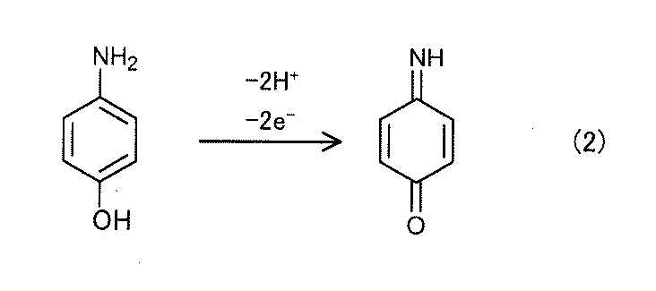
このときにpMAまたはpAPから放出されて作用極が受け取る電子が電流として観察される。電気化学反応により測定される電流値は、pMAまたはpAPの濃度に比例する。エンドトキシンの濃度および多段反応の進行には相関があるため、エンドトキシンの濃度および生じたpMAまたはpAPの濃度、すなわち電流値にも相関が生じる。したがって、エンドトキシンの濃度および電流値の相関を示した検量線を予め作成することにより、電流値から、エンドトキシンの濃度を測定することができる。
電気化学反応を用いたエンドトキシンの濃度検出は、電極表面での反応の検出が可能となり、微量の被検体でもエンドトキシンの濃度を測定することができる。したがって、上記エンドトキシン検出用チップは、微量の被検体でも、例えば、1EU/Lのエンドトキシンを安定的に検出可能となるのみならず、迅速な検出が可能となる。さらに、C因子にB因子および凝固酵素前駆体を含むいわゆるライセート試薬や、C因子等の高価な酵素の使用を大幅に節減することができ、上記エンドトキシン検出用チップは、例えば、1EU/Lのエンドトキシンの検出を安定的に行うことができる。
電気化学反応を用いたエンドトキシンの濃度検出方法は、比色法のように、光により検出する方法ではないため、透明性の低い被検体や、組織液等の多成分系の被検体も測定対象にできると考えられ、実用性が極めて高い。
このように本発明においては、医療現場で、手軽で迅速かつ高精度なエンドトキシンの定量が可能となり、血液と直接接する医薬品や医療器具に対して、エンドトキシンの厳重な混入防止管理を行うことができる。
以下、上記試薬の各構成、固定化位置および遊離反応について詳細に説明する。
以下、上記試薬の各構成、固定化位置および遊離反応について詳細に説明する。
(a)試薬
本発明に用いられる試薬は、C因子、酸化還元物質が結合したペプチド化合物を含むものである。上記試薬は、緩衝液成分を含んでいてもよい。上述の遊離反応の反応速度を向上することができるため、本発明のエンドトキシン検出用チップは、短時間で被検体のエンドトキシン濃度を検出することができるからである。
なお、上記試薬が上記緩衝液成分を含むことにより、C因子および酸化還元物質が結合したペプチド化合物を含み、上記緩衝液成分を含まない従来の試薬を用いて、別途緩衝液を添加して上記遊離反応を行った結果と比較して、上記反応速度を向上できる理由については明確ではないが、上記被検体が上記試薬と接触した際に、上記被検体と接触する、上記C因子、上記ペプチド化合物および上記緩衝液成分の濃度を高くできることが影響していると推察される。
また、上記試薬は櫛歯部が配置された測定領域内に固定化されているものである。
本発明に用いられる試薬は、C因子、酸化還元物質が結合したペプチド化合物を含むものである。上記試薬は、緩衝液成分を含んでいてもよい。上述の遊離反応の反応速度を向上することができるため、本発明のエンドトキシン検出用チップは、短時間で被検体のエンドトキシン濃度を検出することができるからである。
なお、上記試薬が上記緩衝液成分を含むことにより、C因子および酸化還元物質が結合したペプチド化合物を含み、上記緩衝液成分を含まない従来の試薬を用いて、別途緩衝液を添加して上記遊離反応を行った結果と比較して、上記反応速度を向上できる理由については明確ではないが、上記被検体が上記試薬と接触した際に、上記被検体と接触する、上記C因子、上記ペプチド化合物および上記緩衝液成分の濃度を高くできることが影響していると推察される。
また、上記試薬は櫛歯部が配置された測定領域内に固定化されているものである。
上記C因子としては、エンドトキシンにより活性型C因子を生成し、さらに活性型C因子により上記ペプチド化合物から上記酸化還元物質を遊離させる遊離反応を生じさせることができるものであれば特に限定されるものではない。
例えば、上記C因子としては、カブトガニの血球抽出成分等の生体由来成分から単離精製されたC因子、遺伝子組換え技術によって作製された組換えC因子等を適宜使用することができる。
本発明においては、中でも、上記C因子は、B因子および凝固酵素前駆体と共に用いられること、すなわち、上記試薬が、C因子、B因子および凝固酵素前駆体を含有する多段反応用組成物を含むことが好ましい。上記多段階の遊離反応は、上記ペプチド化合物から上記酸化還元物質を効率的に遊離させることができるからである。
上記多段反応用組成物としては、C因子、B因子および凝固酵素前駆体を含むものであれば特に限定されるものではないが、例えば、Limulus Amebocyte Lysate(LAL)といわれるカブトガニの血球抽出成分により調製されたライセート試薬を用いることができる。また、カブトガニの血球抽出成分等の生体由来成分から単離精製されたC因子、B因子および凝固酵素前駆体を組み合わせて調製されたもの等、C因子、B因子および凝固酵素前駆体の少なくとも一つとして、カブトガニの血球抽出成分等の生体由来成分から単離精製されたものを組み合わせて調製されたものもライセート試薬に含まれるものである。このようなライセート試薬を「LALの同等物」として用いることができる。
さらに、上記多段反応用組成物としては、遺伝子組換え技術によって作製された組換えC因子、組み換えB因子、組み換え凝固酵素前駆体を適宜使用して調製したもの等を、「LALの同等物」として用いることもできる。なお、LALおよびLAL同等物を、LAL系試薬と称する場合がある。
例えば、上記C因子としては、カブトガニの血球抽出成分等の生体由来成分から単離精製されたC因子、遺伝子組換え技術によって作製された組換えC因子等を適宜使用することができる。
本発明においては、中でも、上記C因子は、B因子および凝固酵素前駆体と共に用いられること、すなわち、上記試薬が、C因子、B因子および凝固酵素前駆体を含有する多段反応用組成物を含むことが好ましい。上記多段階の遊離反応は、上記ペプチド化合物から上記酸化還元物質を効率的に遊離させることができるからである。
上記多段反応用組成物としては、C因子、B因子および凝固酵素前駆体を含むものであれば特に限定されるものではないが、例えば、Limulus Amebocyte Lysate(LAL)といわれるカブトガニの血球抽出成分により調製されたライセート試薬を用いることができる。また、カブトガニの血球抽出成分等の生体由来成分から単離精製されたC因子、B因子および凝固酵素前駆体を組み合わせて調製されたもの等、C因子、B因子および凝固酵素前駆体の少なくとも一つとして、カブトガニの血球抽出成分等の生体由来成分から単離精製されたものを組み合わせて調製されたものもライセート試薬に含まれるものである。このようなライセート試薬を「LALの同等物」として用いることができる。
さらに、上記多段反応用組成物としては、遺伝子組換え技術によって作製された組換えC因子、組み換えB因子、組み換え凝固酵素前駆体を適宜使用して調製したもの等を、「LALの同等物」として用いることもできる。なお、LALおよびLAL同等物を、LAL系試薬と称する場合がある。
上記C因子または上記多段反応用組成物の上記試薬中の含有量については、精度よくエンドトキシンの濃度を検出できるものであれば特に限定されるものではなく、本発明のエンドトキシン検出用チップにおける被検体の導入量、収容部の有無および上記収容部の容積等に応じて適宜設定されるものである。
上記多段反応用組成物の上記試薬中の含有量としては、例えば、電気化学的方法に用いられるエンドトキシン測定用に市販されている1テスト分のライセート試薬と同量とすることができる。
上記多段反応用組成物の上記試薬中の含有量としては、例えば、電気化学的方法に用いられるエンドトキシン測定用に市販されている1テスト分のライセート試薬と同量とすることができる。
上記酸化還元物質が結合したペプチド化合物としては、酸化還元物質と、酸化還元物質が結合しているオリゴペプチド化合物と、を有するものであればよく、オリゴペプチド化合物の一端に酸化還元物質が結合し、他端にペプチド化合物の保護基が結合したものを用いることができる。このようなペプチド化合物は、例えば、X-A-Yで示されるものを挙げることができる。ここで、Xは保護基、Aはオリゴペプチド化合物、Yは上記酸化還元物質を表す。
保護基Xは、ペプチド化合物の保護基、例えば、t-ブトキシカルボニル基(Boc)、ベンゾイル基、アセテート基等を挙げることができる。
保護基Xは、ペプチド化合物の保護基、例えば、t-ブトキシカルボニル基(Boc)、ベンゾイル基、アセテート基等を挙げることができる。
上記オリゴペプチド化合物としては、C因子または多段反応用組成物の作用によって酸化還元物質を遊離することができるものであれば特に限定されるものではない。中でも、オリゴペプチド化合物は、アミノ酸数が2~10、特に2~5、さらには3~4のものが好ましい。
C因子の作用によって酸化還元物質を遊離可能なC因子用のオリゴペプチドとしては、例えば、C因子用のトリペプチドとして、Val-Pro-Arg、Asp-Pro-Arg、Leu-Gly-Arg等を挙げることができる。
また、上記多段反応用組成物の作用によって酸化還元物質を遊離可能な多段反応用組成物用のトリペプチドとしては、Leu-Gly-Arg、Thr-Gly-Arg等を例示することができる。また、多段反応用組成物用のトリペプチドとしては、例えば、一般式:R1-Gly-Arg-YにおけるL-アミノ酸を有するトリペプチドを挙げることができる。ここで、R1はN-ブロックされたアミノ酸を表す。
また、多段反応用組成物用のオリゴペプチドとしては、一般式:R2-A1-A2-A3-A4-YにおけるテトラペプチドA1-A2-A3-A4を挙げることができる。ここで、R2は水素、ブロックしている芳香族炭化水素またはアシル基を表し、A1はIle、ValまたはLeuから選択されるL-アミノ酸またはD-アミノ酸を表し、A2はGluまたはAspを表し、A3はAlaまたはCysを表し、A4はArgを表す。
オリゴペプチドの一端に酸化還元物質が結合し、他端にペプチドの保護基が結合した多段反応用組成物用のペプチド化合物としては、具体的には、Boc-Leu-Gly-Arg-Y、アセテート-Ile-Glu-Ala-Arg-Y等が挙げられる。
また、多段反応用組成物用のオリゴペプチドとしては、一般式:R2-A1-A2-A3-A4-YにおけるテトラペプチドA1-A2-A3-A4を挙げることができる。ここで、R2は水素、ブロックしている芳香族炭化水素またはアシル基を表し、A1はIle、ValまたはLeuから選択されるL-アミノ酸またはD-アミノ酸を表し、A2はGluまたはAspを表し、A3はAlaまたはCysを表し、A4はArgを表す。
オリゴペプチドの一端に酸化還元物質が結合し、他端にペプチドの保護基が結合した多段反応用組成物用のペプチド化合物としては、具体的には、Boc-Leu-Gly-Arg-Y、アセテート-Ile-Glu-Ala-Arg-Y等が挙げられる。
上記酸化還元物質としては、活性化したC因子または上記活性型凝固酵素により上記ペプチド化合物から遊離することができ、さらに、特定の電位で酸化反応または還元反応を生じるものであればよい。
上記酸化還元物質としては、具体的には、pMA等を含む下記一般式(3)で示す化合物、色素、パラアミノフェノール(pAP)等を挙げることができる。
上記色素としては、具体的には、例えば、2、4-ジニトロアニリン(DNP)、p-ニトロアニリン(pNA)、7-メトキシクマリン-4-酢酸(MCA)、Dansyl色素等を挙げることができる。
上記酸化還元物質としては、具体的には、pMA等を含む下記一般式(3)で示す化合物、色素、パラアミノフェノール(pAP)等を挙げることができる。
上記色素としては、具体的には、例えば、2、4-ジニトロアニリン(DNP)、p-ニトロアニリン(pNA)、7-メトキシクマリン-4-酢酸(MCA)、Dansyl色素等を挙げることができる。

(式(3)中、Rは、-O-CnH2n+1または-S-CnH2n+1であり、nは1から4までの整数である。)
本発明においては、上記一般式(3)で示した化合物がpMAであることが好ましい。上記一般式(3)で示した化合物のアルキル鎖が短い程、水溶性が高くなり、かつ、活性化したC因子または上記活性型凝固酵素が、上記ペプチド化合物に含まれるオリゴペプチド化合物のペプチド化合物配列を認識しやすくなる。このため、酸化還元物質としてオリゴペプチド化合物に結合している上記一般式(3)で示す化合物がpMAであることにより、上記ペプチド化合物は、上記活性化したC因子等との反応性が高まるからである。
本発明においては、上記酸化還元物質が、pMAまたはpAPであることが好ましい。ペプチド化合物から遊離したpMAおよびpAPと、ペプチド化合物に結合したpMAおよびpAPとは、酸化還元電位が異なっており、その差が比較的大きい。そのため、ペプチド化合物から遊離したpMAおよびpAPの酸化反応に由来する電流と、ペプチド化合物に結合したpMAおよびpAPの酸化反応に由来する電流とを容易に分離して得ることができる。したがってpMAまたはpAPが結合したペプチド化合物を用いることにより、ペプチド化合物から遊離したpMAまたはpAPの濃度が極微量であっても、例えば、1EU/Lのエンドトキシンを安定的に検出可能となるからである。
上記ペプチド化合物の上記試薬中の含有量については、例えば、1EU/Lのエンドトキシンを安定的に検出できるものであれば特に限定されるものではなく、本発明のエンドトキシン検出用チップにおける被検体の導入量、収容部の有無および上記収容部の容積等に応じて適宜設定されるものである。
例えば、上記含有量は、上記反応後混合物を形成した際に0.1mM~5.0mMの範囲内となる量とすることができる。
上記反応後混合物の容積としては、上記被検体の容積とほぼ同量とすることができ、数μL~数十μLの範囲内とすることができる。
例えば、上記含有量は、上記反応後混合物を形成した際に0.1mM~5.0mMの範囲内となる量とすることができる。
上記反応後混合物の容積としては、上記被検体の容積とほぼ同量とすることができ、数μL~数十μLの範囲内とすることができる。
また、上記C因子または上記多段反応用組成物と、上記酸化還元物質が結合したペプチド化合物との合計の含有量は、精度よくエンドトキシンの濃度を検出できるものであれば特に限定されるものではなく、本発明のエンドトキシン検出用チップにおける被検体の導入量、収容部の有無および上記収容部の容積等に応じて適宜設定されるものである。
上記多段反応用組成物と上記ペプチド化合物との合計の含有量としては、例えば、1mg~10mgの範囲内とすることができ、中でも1mg~4mgの範囲内であることが好ましい。高価な酵素等の含有量を少ないものとすることができ、本発明のエンドトキシン検出用チップは、低価格化を図ることができるからである。
上記多段反応用組成物と上記ペプチド化合物との合計の含有量としては、例えば、1mg~10mgの範囲内とすることができ、中でも1mg~4mgの範囲内であることが好ましい。高価な酵素等の含有量を少ないものとすることができ、本発明のエンドトキシン検出用チップは、低価格化を図ることができるからである。
上記緩衝液成分は、緩衝液から水を乾燥除去した際に残る緩衝液の固形分であり、純水を添加することにより所望の緩衝能を示す緩衝液を生成可能なものであればよい。
上記緩衝液成分は、酸化還元物質を安定的に遊離できる緩衝液を生成可能なものであれば特に限定されるものではなく、例えば、pH6.0~9.0、中でもpH7.0~8.5の緩衝液の成分であることが好ましい。これにより、酸化還元物質の遊離量を増加させることができるからである。
上記緩衝液成分は、例えば、トリス酢酸(Tris-acetate)緩衝液、トリス塩酸(Tris-HCl)緩衝液、リン酸緩衝液、HEPES(4-(2-hydroxyethyl)-1-piperazineethanesulfonic acid)緩衝液、PIPES(Piperazine-1,4-bis(2-ethanesulfonic acid)緩衝液等の成分が挙げられる。
上記緩衝液成分は、酸化還元物質を安定的に遊離できる緩衝液を生成可能なものであれば特に限定されるものではなく、例えば、pH6.0~9.0、中でもpH7.0~8.5の緩衝液の成分であることが好ましい。これにより、酸化還元物質の遊離量を増加させることができるからである。
上記緩衝液成分は、例えば、トリス酢酸(Tris-acetate)緩衝液、トリス塩酸(Tris-HCl)緩衝液、リン酸緩衝液、HEPES(4-(2-hydroxyethyl)-1-piperazineethanesulfonic acid)緩衝液、PIPES(Piperazine-1,4-bis(2-ethanesulfonic acid)緩衝液等の成分が挙げられる。
上記緩衝液成分の上記試薬中の含有割合については、所望のpH範囲の緩衝液を生成可能なものであれば特に限定されるものではなく、本発明のエンドトキシン検出用チップにおける被検体の導入量、収容部の有無および上記収容部の容積等に応じて適宜設定されるものである。
例えば、上記含有割合は、上記反応後混合物を形成した際に上記各緩衝液を生成可能な量とすることができる。
例えば、上記含有割合は、上記反応後混合物を形成した際に上記各緩衝液を生成可能な量とすることができる。
上記試薬は、C因子、酸化還元物質が結合したペプチド化合物を少なくとも含み、さらに、B因子および凝固酵素前駆体ならびに緩衝液成分を含むことが好ましいものであるが、さらに必要に応じてその他の成分を含むものであってもよい。
上記その他の成分としては、上記ペプチド化合物から遊離した酸化還元物質と反応可能な第2酸化還元物質を挙げることができる。上記酸化還元物質と反応した後の第2酸化還元物質を電極により酸化還元反応させることで、本発明のエンドトキシン検出用チップは、エンドトキシンの濃度をより精度よく検出することが可能となるからである。
上記第2酸化還元物質は、上記酸化還元物質に応じて適宜選択することができる。
上記その他の成分としては、上記ペプチド化合物から遊離した酸化還元物質と反応可能な第2酸化還元物質を挙げることができる。上記酸化還元物質と反応した後の第2酸化還元物質を電極により酸化還元反応させることで、本発明のエンドトキシン検出用チップは、エンドトキシンの濃度をより精度よく検出することが可能となるからである。
上記第2酸化還元物質は、上記酸化還元物質に応じて適宜選択することができる。
上記試薬は、多数の孔を有し、同じ体積を持つ孔の無い構造(非多孔質構造)よりも表面積が拡大されている多孔質構造であってもよく、非多孔質構造であってもよい。上記櫛歯部が配置された測定領域内に固定化されている上記試薬が多孔質構造である場合には、上記試薬が上記被検体に速やかに溶解するからである。また、上記非多孔質構造である場合には、上記試薬の乾燥方法として後述するような常温常圧での乾燥方法を用いることができ、簡便な設備で上記試薬を形成できるからである。
また、上記試薬が多孔質構造であるか非多孔質構造であるかの判断方法としては、上記固定化されている上記試薬が白濁している場合には多孔質構造であり、透明性を有している場合には非多孔質構造であると目視により判断する方法や、走査型電子顕微鏡(SEM)による観察等により確認する方法が挙げられる。
また、上記試薬が多孔質構造であるか非多孔質構造であるかの判断方法としては、上記固定化されている上記試薬が白濁している場合には多孔質構造であり、透明性を有している場合には非多孔質構造であると目視により判断する方法や、走査型電子顕微鏡(SEM)による観察等により確認する方法が挙げられる。
(b)試薬の固定化方法
上記試薬の固定化方法としては、上記試薬を上記櫛歯部が配置された測定領域内に固定化できる方法であれば特に限定されるものではなく、上記C因子または上記多段反応用組成物、上記ペプチド化合物および上記緩衝液成分や、上記その他の成分等を含む試薬溶液を調製した後、上記櫛歯部が配置された測定領域内の上記試薬を固定化する位置に上記試薬溶液を塗布し乾燥する方法を用いることができる。
上記乾燥方法としては、上記試薬溶液から水を除去できる方法であれば特に限定されるものではなく、常温および大気圧下で乾燥する方法、減圧状態で乾燥する真空乾燥法等を用いることができる。本発明においては、中でも、上記乾燥方法が上記真空乾燥法であることが好ましい。上記乾燥方法が上記真空乾燥法であることにより、空気中のエンドトキシンの混入を防止した状態で上記試薬溶液を乾燥させることができるからである。また、短時間で常温以下での乾燥が可能となることから、低コスト化、エンドトキシンの混入リスクの低減、上記試薬に含まれるC因子、B因子および凝固酵素前駆体等が変性し、活性化しない構造となることの抑制等を図ることができるからである。また、上記乾燥方法が上記真空乾燥法等である場合には、上記試薬を多孔質構造とすることができるからである。
本発明においては、特に、上記真空乾燥法が凍結乾燥法であることが好ましい。上記試薬をより低密度な多孔質構造、すなわち、より空隙部の体積が大きく、表面積の広いものとすることができ、上記試薬は、上記被検体への溶解速度に優れたものとなるからである。
一方、上記乾燥方法が大気圧下で乾燥する方法である場合には、上記試薬溶液を乾燥して所望の位置および範囲に固定化するために要するコストを低減することができるからである。
上記試薬の固定化方法としては、上記試薬を上記櫛歯部が配置された測定領域内に固定化できる方法であれば特に限定されるものではなく、上記C因子または上記多段反応用組成物、上記ペプチド化合物および上記緩衝液成分や、上記その他の成分等を含む試薬溶液を調製した後、上記櫛歯部が配置された測定領域内の上記試薬を固定化する位置に上記試薬溶液を塗布し乾燥する方法を用いることができる。
上記乾燥方法としては、上記試薬溶液から水を除去できる方法であれば特に限定されるものではなく、常温および大気圧下で乾燥する方法、減圧状態で乾燥する真空乾燥法等を用いることができる。本発明においては、中でも、上記乾燥方法が上記真空乾燥法であることが好ましい。上記乾燥方法が上記真空乾燥法であることにより、空気中のエンドトキシンの混入を防止した状態で上記試薬溶液を乾燥させることができるからである。また、短時間で常温以下での乾燥が可能となることから、低コスト化、エンドトキシンの混入リスクの低減、上記試薬に含まれるC因子、B因子および凝固酵素前駆体等が変性し、活性化しない構造となることの抑制等を図ることができるからである。また、上記乾燥方法が上記真空乾燥法等である場合には、上記試薬を多孔質構造とすることができるからである。
本発明においては、特に、上記真空乾燥法が凍結乾燥法であることが好ましい。上記試薬をより低密度な多孔質構造、すなわち、より空隙部の体積が大きく、表面積の広いものとすることができ、上記試薬は、上記被検体への溶解速度に優れたものとなるからである。
一方、上記乾燥方法が大気圧下で乾燥する方法である場合には、上記試薬溶液を乾燥して所望の位置および範囲に固定化するために要するコストを低減することができるからである。
(c)試薬の固定化位置
上記試薬は、上記測定領域内に固定化されるものである。
上記試薬の固定化位置は、上記測定領域内であり、導入される上記被検体と接触することができる位置であればよい。具体的には、図3の試薬11で示すように、2つの作用極3の櫛歯部3bの全てを被覆するように形成されていてもよいし、櫛歯部3bの一部を被覆するように形成されていてもよい。導入口から被検体を導入する場合は、導入口の直下に上記試薬が固定化されていてもよい。
なお、上記測定領域とは、上述のように、上記電極部が配置され、電気化学反応により電流値の測定がおこなわれる領域のことである。具体的には、上記電極部を囲む領域をいい、図1のMで示される領域とすることができる。上記測定領域Mは、上記電極部6(作用極3、対極4および参照極5等)の測定に関与する全ての部分(例えば、櫛形電極の櫛歯部3b等)を含むことが好ましく、具体的には、上記測定に関与する部分の端部(例えば、櫛歯部3bの先端部分、対極および参照極の作用極と対向する反対側の面)を含む最小の長方形であることが好ましい。上記エンドトキシン検出用チップはサイズの小さいものとなることが容易であり、また、精度よくエンドトキシンの濃度の検出を行うことができるからである。
上記試薬は、上記測定領域内に固定化されるものである。
上記試薬の固定化位置は、上記測定領域内であり、導入される上記被検体と接触することができる位置であればよい。具体的には、図3の試薬11で示すように、2つの作用極3の櫛歯部3bの全てを被覆するように形成されていてもよいし、櫛歯部3bの一部を被覆するように形成されていてもよい。導入口から被検体を導入する場合は、導入口の直下に上記試薬が固定化されていてもよい。
なお、上記測定領域とは、上述のように、上記電極部が配置され、電気化学反応により電流値の測定がおこなわれる領域のことである。具体的には、上記電極部を囲む領域をいい、図1のMで示される領域とすることができる。上記測定領域Mは、上記電極部6(作用極3、対極4および参照極5等)の測定に関与する全ての部分(例えば、櫛形電極の櫛歯部3b等)を含むことが好ましく、具体的には、上記測定に関与する部分の端部(例えば、櫛歯部3bの先端部分、対極および参照極の作用極と対向する反対側の面)を含む最小の長方形であることが好ましい。上記エンドトキシン検出用チップはサイズの小さいものとなることが容易であり、また、精度よくエンドトキシンの濃度の検出を行うことができるからである。
本発明によれば、C因子および酸化還元物質が結合したペプチド化合物と共に、緩衝液成分を含む試薬が、上記櫛歯部が配置された測定領域内に固定化されていることにより、緩衝液の添加を行うことなく被検体を上記収容部内に導入することのみで、電気化学反応による電流値の測定対象となる、上記反応後混合物を得ることが可能となる。
したがって、上記エンドトキシン検出用チップを、例えば、1EU/Lのエンドトキシンを安定的に検出可能なものとすることができる。
したがって、上記エンドトキシン検出用チップを、例えば、1EU/Lのエンドトキシンを安定的に検出可能なものとすることができる。
6.用途
本発明のエンドトキシン検出用チップの用途は、例えば、1EU/Lのエンドトキシンの検出に用いるものとすることができるが、1EU/Lに限定されず、1EU/L近傍のエンドトキシンの検出に用いることができる。
1EU/L近傍としては、例えば、0.5EU/L~5EU/Lの範囲内とすることができ、なかでも、0.5EU/L~3EU/Lの範囲内であることが好ましく、特に、0.5EU/L~2EU/Lの範囲内であることが好ましい。1EU/L近傍として、上述の範囲内のエンドトキシンであることにより、上述の増幅率であることにより安定的にエンドトキシンを検出できるとの本発明の効果を効果的に発揮できるからである。
本発明のエンドトキシン検出用チップの用途は、例えば、1EU/Lのエンドトキシンの検出に用いるものとすることができるが、1EU/Lに限定されず、1EU/L近傍のエンドトキシンの検出に用いることができる。
1EU/L近傍としては、例えば、0.5EU/L~5EU/Lの範囲内とすることができ、なかでも、0.5EU/L~3EU/Lの範囲内であることが好ましく、特に、0.5EU/L~2EU/Lの範囲内であることが好ましい。1EU/L近傍として、上述の範囲内のエンドトキシンであることにより、上述の増幅率であることにより安定的にエンドトキシンを検出できるとの本発明の効果を効果的に発揮できるからである。
また、本発明のエンドトキシン検出用チップにより測定される被検体としては、例えば血液、唾液、汗、尿等の生体試料や、環境検査の対象物、食品、化粧品、廃液、樹脂等を挙げることができる。また、被検体としては、透析液、注射薬等の医薬品や医療用具等を挙げることができる。
なお、上記被検体については、液体試料に限定されず、気体試料も含むことができるが、通常、液体試料である。
また、上記被検体が固体である場合には、緩衝液等の適当な溶媒に溶解または分散した液体試料を測定対象の被検体として用いることができる。
なお、上記被検体については、液体試料に限定されず、気体試料も含むことができるが、通常、液体試料である。
また、上記被検体が固体である場合には、緩衝液等の適当な溶媒に溶解または分散した液体試料を測定対象の被検体として用いることができる。
B.エンドトキシン濃度の定量方法
本発明のエンドトキシン濃度の定量方法は、上述したエンドトキシン検出用チップを用いることを特徴とする。
本発明のエンドトキシン濃度の定量方法は、上述したエンドトキシン検出用チップを用いることを特徴とする。
本発明によれば、上述したエンドトキシン検出用チップを用いることで、精度よくエンドトキシン濃度を定量できる。本発明におけるエンドトキシン検出用チップについては、上記「A.エンドトキシン検出用チップ」に記載した内容と同様であるので、ここでの記載は省略する。
また、上述したように、電気化学反応により測定される電流値(例えばpMAまたはpAPの酸化反応により測定される反応電流値)と、エンドトキシン濃度との間には相関があるため、この相関を示した検量線を予め作成することにより、反応電流値から、エンドトキシン濃度を定量することができる。また、エンドトキシン濃度の定量は、被検体を投入し、所定の時間保持した後に行われることが好ましい。保持時間は、例えば60分間以下であり、50分間以下であってもよく、40分間以下であってもよい。一方、保持時間は、例えば、30分間以上であり、35分間以上であってもよい。また、保持温度は、特に限定されないが、37℃近辺であることが好ましい。
特に、エンドトキシン検出用チップは、上記作用極として用いられる櫛形電極の櫛歯部が配置された測定領域内に、C因子と酸化還元物質が結合したペプチド化合物とを含む試薬が固定化されており、上記2つの作用極の材料がPdであり、上記試薬がLAL系試薬であることが好ましい。また、アンペロメトリー法による測定で得られる酸化電位側電流における、パルス印加直前における電流値と、パルス印加後における電流値との差を反応電流値として用いることにより、エンドトキシン濃度を定量することが好ましい。Pd電極およびLAL系試薬を組み合わせた場合、パルス印加直前における電流値が負の値となり、その値もエンドトキシン濃度によって変化する。その電流値を基準とすることで、精度よくエンドトキシン濃度を定量できる。なお、パルス印加後における電流値は、電流値の時間的変動が、エンドトキシン濃度の定量において無視できる程度に少なくなった時点での電流値である。例えば、パルス印加後10秒後であってもよく、20秒後であってもよく、30秒後であってもよい。
なお、本発明は、上記実施形態に限定されるものではない。上記実施形態は、例示であり、本発明の特許請求の範囲に記載された技術的思想と実質的に同一な構成を有し、同様な作用効果を奏するものは、いかなるものであっても本発明の技術的範囲に包含される。
以下、本発明について、実施例を用いて、具体的に説明する。
[実施例1]
PET基材(東レ社製、ルミラー350H10)上に、スパッタリング法により50nm厚の金のスパッタ膜を形成した後、フォトリソグラフィ法によりエッチングを行い、既に説明した図1に示すような2つの作用極としての交互櫛形電極、1つの対極および1つの標準電極を含む電極部、端子部および配線部を有するパターン形状の金層を形成し、エンドトキシン検出用チップを得た。また、標準電極の金層の上に、Ag/AgCl層をスクリーン印刷法にて形成した。このようにして、エンドトキシン検出用チップを得た。
なお、交互櫛形電極を構成する2つの櫛形電極は、それぞれ櫛歯部の幅(図1中のa)および櫛歯部間の幅(図1中のc)を9μmおよび27μmとし、2つの櫛形電極の櫛歯部間のスペース(図1中のS)を9μmとした。
また、2つの作用極の面積は、4.5mm2であった。
PET基材(東レ社製、ルミラー350H10)上に、スパッタリング法により50nm厚の金のスパッタ膜を形成した後、フォトリソグラフィ法によりエッチングを行い、既に説明した図1に示すような2つの作用極としての交互櫛形電極、1つの対極および1つの標準電極を含む電極部、端子部および配線部を有するパターン形状の金層を形成し、エンドトキシン検出用チップを得た。また、標準電極の金層の上に、Ag/AgCl層をスクリーン印刷法にて形成した。このようにして、エンドトキシン検出用チップを得た。
なお、交互櫛形電極を構成する2つの櫛形電極は、それぞれ櫛歯部の幅(図1中のa)および櫛歯部間の幅(図1中のc)を9μmおよび27μmとし、2つの櫛形電極の櫛歯部間のスペース(図1中のS)を9μmとした。
また、2つの作用極の面積は、4.5mm2であった。
[評価1]
(サンプル溶液1の調製)
0.1M KCl水溶液にp-アミノフェノール(pAP)を溶解してpAP濃度を0.5 mMとしたpAP水溶液(サンプル溶液1)を準備した。
(サンプル溶液1の調製)
0.1M KCl水溶液にp-アミノフェノール(pAP)を溶解してpAP濃度を0.5 mMとしたpAP水溶液(サンプル溶液1)を準備した。
(サイクリックボルタモグラムの測定)
サンプル溶液1を2つの作用極の平面視上露出する部位の全てを覆うように30μL滴下して、一方の作用極のみに電位走査速度を100mV/sで、電位(0V→0.6V→-0.2V→0V)を走査して測定されるシングルモードのサイクリックボルタモグラムから得られる0.6Vにおける電流値(基準電流値A1)と、他方の作用極に還元電位を0Vに固定して印加し、一方の作用極に電位走査速度を100mV/sで、電位(0V→0.6V→-0.2V→0V)を走査して測定されるデュアルモードサイクリックボルタモグラムから得られる一方の作用極の0.6Vにおける電流値(測定時電流値A2)と、を得た。
その結果、シングルモードおよびデュアルモードのサイクリックボルタモグラムから得られた基準電流値A1および測定時電流値A2はそれぞれ、1.44μAおよび7.36μAであり、増幅率(A2/A1)は5.1倍であった。
なお、測定されたシングルモードおよびデュアルモードのサイクリックボルタモグラムの結果を図8(a)および(b)に示す。なお、図8(b)中CH1は電位(0V→0.6V→-0.2V→0V)を走査した側の一方の作用極での酸化電流を示し、CH2は、電位を固定した側の他方の作用極での還元電流を示すものである。
また、図8(a)中のA1および図8(b)中のA2は、それぞれ、基準電流値および測定時電流値である。
さらに、図8中横軸は電圧(V)であり、縦軸は反応電流(μA)である。
なお、以下、本実施例では測定装置としてIvium Technologies社製のポテンショスタットCompactStatを使用した。
サンプル溶液1を2つの作用極の平面視上露出する部位の全てを覆うように30μL滴下して、一方の作用極のみに電位走査速度を100mV/sで、電位(0V→0.6V→-0.2V→0V)を走査して測定されるシングルモードのサイクリックボルタモグラムから得られる0.6Vにおける電流値(基準電流値A1)と、他方の作用極に還元電位を0Vに固定して印加し、一方の作用極に電位走査速度を100mV/sで、電位(0V→0.6V→-0.2V→0V)を走査して測定されるデュアルモードサイクリックボルタモグラムから得られる一方の作用極の0.6Vにおける電流値(測定時電流値A2)と、を得た。
その結果、シングルモードおよびデュアルモードのサイクリックボルタモグラムから得られた基準電流値A1および測定時電流値A2はそれぞれ、1.44μAおよび7.36μAであり、増幅率(A2/A1)は5.1倍であった。
なお、測定されたシングルモードおよびデュアルモードのサイクリックボルタモグラムの結果を図8(a)および(b)に示す。なお、図8(b)中CH1は電位(0V→0.6V→-0.2V→0V)を走査した側の一方の作用極での酸化電流を示し、CH2は、電位を固定した側の他方の作用極での還元電流を示すものである。
また、図8(a)中のA1および図8(b)中のA2は、それぞれ、基準電流値および測定時電流値である。
さらに、図8中横軸は電圧(V)であり、縦軸は反応電流(μA)である。
なお、以下、本実施例では測定装置としてIvium Technologies社製のポテンショスタットCompactStatを使用した。
[評価2]
(サンプル溶液2の調製)
ライセート試薬として、ライセート試薬が凍結乾燥状態で1テスト分ずつ専用の試験管に封入されている、生化学工業社製のエンドスペシーES24-Mの1本の試験管に緩衝液180μL、10mM LGR-pAPを20μL添加し、撹拌した。
次いで、蒸留水(0EU/L)を200μL投入して、撹拌し、サンプル溶液(サンプル溶液2)を得た。
なお、ペプチド化合物であるLGR-pAPは、Boc-Leu-Gly-Arg-pAPを用い、大塚製薬社製の注射用水に溶解し、10mMのストック溶液として-20℃で保管していたものを使用した。
LGR-pAPは、特開2015-187607号公報に記載の方法を用いて合成した。
また、緩衝液は、生化学工業社製のエンドスペシーES24-Mに添付されている緩衝液を用いた。
(サンプル溶液2の調製)
ライセート試薬として、ライセート試薬が凍結乾燥状態で1テスト分ずつ専用の試験管に封入されている、生化学工業社製のエンドスペシーES24-Mの1本の試験管に緩衝液180μL、10mM LGR-pAPを20μL添加し、撹拌した。
次いで、蒸留水(0EU/L)を200μL投入して、撹拌し、サンプル溶液(サンプル溶液2)を得た。
なお、ペプチド化合物であるLGR-pAPは、Boc-Leu-Gly-Arg-pAPを用い、大塚製薬社製の注射用水に溶解し、10mMのストック溶液として-20℃で保管していたものを使用した。
LGR-pAPは、特開2015-187607号公報に記載の方法を用いて合成した。
また、緩衝液は、生化学工業社製のエンドスペシーES24-Mに添付されている緩衝液を用いた。
(クロノアンペロメトリー特性の測定)
実施例1で得られたエンドトキシン検出用チップの電極部全てを覆うようにサンプル溶液2を滴下後、アンペロメトリー法を用いて、クロノアンペロメトリー特性を測定し、測定時出力電流値を測定した。サンプル溶液2を滴下後、37℃で60分間保持した後のタイミングで測定した結果を図9に示す。
なお、図9中Y1は、還元電位側電流を示し、Y2は、酸化電位側電流を示し、C1は、還元電位を-0.2Vに固定し、かつ酸化電位を-0.2Vの初期電位を10秒間印加した後、0.4Vに電位をステップ(パルス印加)して10秒間印加したときの、pAPの酸化還元反応に由来した電流値である測定時出力電流値を示すものである。また、図9中、横軸は時間(秒)であり、縦軸は反応電流(A)である。
また、アンペロメトリー法では還元電位を-0.2Vに固定し、かつ還元電位を-0.2Vの初期電位を10秒間印加した後、0.4Vに電位をステップ(パルス印加)して10秒間印加したときの、pAPの酸化還元反応に由来した電流を記録した。
また、図9より、パルス印加から10秒後の測定時出力電流値は50nAであった。
実施例1で得られたエンドトキシン検出用チップの電極部全てを覆うようにサンプル溶液2を滴下後、アンペロメトリー法を用いて、クロノアンペロメトリー特性を測定し、測定時出力電流値を測定した。サンプル溶液2を滴下後、37℃で60分間保持した後のタイミングで測定した結果を図9に示す。
なお、図9中Y1は、還元電位側電流を示し、Y2は、酸化電位側電流を示し、C1は、還元電位を-0.2Vに固定し、かつ酸化電位を-0.2Vの初期電位を10秒間印加した後、0.4Vに電位をステップ(パルス印加)して10秒間印加したときの、pAPの酸化還元反応に由来した電流値である測定時出力電流値を示すものである。また、図9中、横軸は時間(秒)であり、縦軸は反応電流(A)である。
また、アンペロメトリー法では還元電位を-0.2Vに固定し、かつ還元電位を-0.2Vの初期電位を10秒間印加した後、0.4Vに電位をステップ(パルス印加)して10秒間印加したときの、pAPの酸化還元反応に由来した電流を記録した。
また、図9より、パルス印加から10秒後の測定時出力電流値は50nAであった。
[評価3]
蒸留水(0EU/L)にエンドトキシンを混ぜ、1EU/Lのエンドトキシン溶液を調製した。
次いで、1EU/Lのエンドトキシン溶液200μLを蒸留水(0EU/L)200μLの代わりに使用した以外は、評価2と同様にしてサンプル溶液(サンプル溶液3)を得た。
このようにして得られたサンプル溶液3を用いた以外は、評価2と同様にして、クロノアンペロメトリー特性の測定を行った。その結果を図10に示す。
その結果、図10より、パルス印加から10秒後の測定時出力電流値は250nAであった。
なお、蒸留水(0EU/L)に添加したエンドトキシンは、生化学工業社製のE.Coli O113:H10株由来USP Reference Standard Endotoxinを用いた。
蒸留水(0EU/L)にエンドトキシンを混ぜ、1EU/Lのエンドトキシン溶液を調製した。
次いで、1EU/Lのエンドトキシン溶液200μLを蒸留水(0EU/L)200μLの代わりに使用した以外は、評価2と同様にしてサンプル溶液(サンプル溶液3)を得た。
このようにして得られたサンプル溶液3を用いた以外は、評価2と同様にして、クロノアンペロメトリー特性の測定を行った。その結果を図10に示す。
その結果、図10より、パルス印加から10秒後の測定時出力電流値は250nAであった。
なお、蒸留水(0EU/L)に添加したエンドトキシンは、生化学工業社製のE.Coli O113:H10株由来USP Reference Standard Endotoxinを用いた。
[まとめ]
評価1~3より、レドックスサイクリング誘導時の増幅率が5倍以上であることにより、例えば、クロノアンペロメトリー特性の測定結果から得られる測定時出力電流値が、0EU/Lと1EU/Lとでは、安定的に重複しないことが確認できた。
評価1~3より、レドックスサイクリング誘導時の増幅率が5倍以上であることにより、例えば、クロノアンペロメトリー特性の測定結果から得られる測定時出力電流値が、0EU/Lと1EU/Lとでは、安定的に重複しないことが確認できた。
[実施例2]
PET基材(東レ社製、ルミラー350H10)上に、スパッタリング法により50nm厚のPdのスパッタ膜を形成した後、フォトリソグラフィ法によりエッチングを行い、既に説明した図1に示すような2つの作用極としての交互櫛形電極、1つの対極および1つの標準電極を含む電極部、端子部および配線部を有するパターン形状のPd層を形成し、エンドトキシン検出用チップを得た。なお、Pdは標準電極としての適用可能であり、Au電極のようなAg/AgCl層の形成は不要である。
また、交互櫛形電極を構成する2つの櫛形電極は、それぞれ櫛歯部の幅(図1中のa)および櫛歯部間の幅(図1中のc)を9μmおよび27μmとし、2つの櫛形電極の櫛歯部間のスペース(図1中のS)を9μmとした。
また、2つの作用極の面積は、4.5mm2であった。
PET基材(東レ社製、ルミラー350H10)上に、スパッタリング法により50nm厚のPdのスパッタ膜を形成した後、フォトリソグラフィ法によりエッチングを行い、既に説明した図1に示すような2つの作用極としての交互櫛形電極、1つの対極および1つの標準電極を含む電極部、端子部および配線部を有するパターン形状のPd層を形成し、エンドトキシン検出用チップを得た。なお、Pdは標準電極としての適用可能であり、Au電極のようなAg/AgCl層の形成は不要である。
また、交互櫛形電極を構成する2つの櫛形電極は、それぞれ櫛歯部の幅(図1中のa)および櫛歯部間の幅(図1中のc)を9μmおよび27μmとし、2つの櫛形電極の櫛歯部間のスペース(図1中のS)を9μmとした。
また、2つの作用極の面積は、4.5mm2であった。
[評価4]
実施例1と同様にして、サンプル溶液1を得た。得られたサンプル溶液1を用い、実施例1と同様にして、サイクリックボルタモグラム測定を行った。その結果、シングルモードおよびデュアルモードのサイクリックボルタモグラムから得られた基準電流値A1および測定時電流値A2はそれぞれ、1.4μAおよび7.5μAであり、増幅率(A2/A1)は5.3倍であった。
実施例1と同様にして、サンプル溶液1を得た。得られたサンプル溶液1を用い、実施例1と同様にして、サイクリックボルタモグラム測定を行った。その結果、シングルモードおよびデュアルモードのサイクリックボルタモグラムから得られた基準電流値A1および測定時電流値A2はそれぞれ、1.4μAおよび7.5μAであり、増幅率(A2/A1)は5.3倍であった。
[評価5]
ライセート試薬として、構成因子であるC因子、B因子および凝固酵素前駆体の3種類それぞれに、遺伝子組換え技術によって作製された組換えタンパク質を用いた試薬を使用した以外は、実施例1と同様にして、サンプル溶液2を得た。得られたサンプル溶液2を用い、クロノアンペロメトリー特性の測定を行った。実施例2で得られたエンドトキシン検出用チップの電極部全てを覆うようにサンプル溶液2を滴下後、アンペロメトリー法を用いて、クロノアンペロメトリー特性を測定し、測定時出力電流値(酸化電位側電流値)を測定した。サンプル溶液2を滴下後、37℃で、30分間、35分間、40分間保持した後のタイミングでそれぞれ測定を行った。なお、パルスの印加条件は、パルス印加の際に0.2Vに電位をステップさせた以外は実施例1と同様である。
ライセート試薬として、構成因子であるC因子、B因子および凝固酵素前駆体の3種類それぞれに、遺伝子組換え技術によって作製された組換えタンパク質を用いた試薬を使用した以外は、実施例1と同様にして、サンプル溶液2を得た。得られたサンプル溶液2を用い、クロノアンペロメトリー特性の測定を行った。実施例2で得られたエンドトキシン検出用チップの電極部全てを覆うようにサンプル溶液2を滴下後、アンペロメトリー法を用いて、クロノアンペロメトリー特性を測定し、測定時出力電流値(酸化電位側電流値)を測定した。サンプル溶液2を滴下後、37℃で、30分間、35分間、40分間保持した後のタイミングでそれぞれ測定を行った。なお、パルスの印加条件は、パルス印加の際に0.2Vに電位をステップさせた以外は実施例1と同様である。
[評価6]
蒸留水(0EU/L)にエンドトキシンを混ぜ、1EU/Lのエンドトキシン溶液を調製した。
次いで、1EU/Lのエンドトキシン溶液200μLを蒸留水(0EU/L)200μLの代わりに使用した以外は、評価5と同様にしてサンプル溶液(サンプル溶液3、遺伝子組換えタイプ)を得た。
得られたサンプル溶液3を用い、クロノアンペロメトリー特性の測定を行った。測定条件は、評価5と同じである。
蒸留水(0EU/L)にエンドトキシンを混ぜ、1EU/Lのエンドトキシン溶液を調製した。
次いで、1EU/Lのエンドトキシン溶液200μLを蒸留水(0EU/L)200μLの代わりに使用した以外は、評価5と同様にしてサンプル溶液(サンプル溶液3、遺伝子組換えタイプ)を得た。
得られたサンプル溶液3を用い、クロノアンペロメトリー特性の測定を行った。測定条件は、評価5と同じである。
[まとめ]
クロノアンペロメトリー特性の測定結果の一例を図11に示す。図11(a)および図11(b)は、それぞれ、保持時間が35分間である場合の評価5、6の結果である。図11(a)および図11(b)に示すように、グラウンド電流0nAを基準とした場合、パルス印加から10秒後における反応電流値は、図11(a)および図11(b)でほぼ同じであり、差が小さかった。これは、エンドトキシン濃度が非常に低いためである。一方で、Pd電極およびLAL系試薬を用いた場合は、パルス印加直前における電流値(図中、Xで示される位置の電流値)は、0nAではなく、負の値となり、その値もエンドトキシン濃度によって変化した。
クロノアンペロメトリー特性の測定結果の一例を図11に示す。図11(a)および図11(b)は、それぞれ、保持時間が35分間である場合の評価5、6の結果である。図11(a)および図11(b)に示すように、グラウンド電流0nAを基準とした場合、パルス印加から10秒後における反応電流値は、図11(a)および図11(b)でほぼ同じであり、差が小さかった。これは、エンドトキシン濃度が非常に低いためである。一方で、Pd電極およびLAL系試薬を用いた場合は、パルス印加直前における電流値(図中、Xで示される位置の電流値)は、0nAではなく、負の値となり、その値もエンドトキシン濃度によって変化した。
そのため、グラウンド電流(0nA)を基準とする代わりに、パルス印加直前における電流値を基準とすると、図11(c)に示すように、パルス印加から10秒後における反応電流値の差が大きくなった。具体的に、CAは35nAであり、CBは63nAであり、CB/CAは1.8であった。なお、この反応電流値の規定方法は、エンドトキシン濃度によってパルス印加直前における電流値が変化する点を応用した方法である。また、図11は、保持時間が35分間である場合の結果であるが、保持時間が30分間である場合および40分間である場合についても、同様に、反応電流値を規定した。その結果を図12に示す。図12に示すように、保持時間の増加とともに、CB/CAの値も大きくなり、保持時間35分間の時点で、CB/CAの値が1.5倍以上となった。
[実施例3]
実施例1と同様にして、エンドトキシン検出用チップを得た。
実施例1と同様にして、エンドトキシン検出用チップを得た。
[評価7]
実施例1と同様にして、サンプル溶液1を得た。サンプル溶液1を用い、実施例1と同様にして、サイクリックボルタモグラム測定を行った。その結果は、実施例1と同じであった。
実施例1と同様にして、サンプル溶液1を得た。サンプル溶液1を用い、実施例1と同様にして、サイクリックボルタモグラム測定を行った。その結果は、実施例1と同じであった。
[評価8]
実施例2と同様にして、サンプル溶液1を得た。得られたサンプル溶液2を用い、クロノアンペロメトリー特性の測定を行った。実施例3で得られたエンドトキシン検出用チップの電極部全てを覆うようにサンプル溶液2を滴下後、アンペロメトリー法を用いて、クロノアンペロメトリー特性を測定し、測定時出力電流値(還元電位側電流値)を測定した。サンプル溶液2を滴下後、37℃で、60分間保持した後のタイミングで測定を行った。なお、パルスの印加条件は、実施例2と同様である。
実施例2と同様にして、サンプル溶液1を得た。得られたサンプル溶液2を用い、クロノアンペロメトリー特性の測定を行った。実施例3で得られたエンドトキシン検出用チップの電極部全てを覆うようにサンプル溶液2を滴下後、アンペロメトリー法を用いて、クロノアンペロメトリー特性を測定し、測定時出力電流値(還元電位側電流値)を測定した。サンプル溶液2を滴下後、37℃で、60分間保持した後のタイミングで測定を行った。なお、パルスの印加条件は、実施例2と同様である。
[評価9]
実施例2と同様にして、サンプル溶液3を得た。得られたサンプル溶液3を用い、クロノアンペロメトリー特性の測定を行った。測定条件は、評価8と同じである。
実施例2と同様にして、サンプル溶液3を得た。得られたサンプル溶液3を用い、クロノアンペロメトリー特性の測定を行った。測定条件は、評価8と同じである。
[まとめ]
クロノアンペロメトリー特性の測定結果を図13および図14に示す。図13および図14に示すように、0EU/Lの場合、パルス印加から10秒後の測定時出力電流値(CA)は21.4nAであり、1EU/Lの場合、パルス印加から10秒後の測定時出力電流値(CB)は59.9nAであり、CB/CAは、2.8倍であった。なお、被検体サンプルを測定領域内で60分間保持した状態におけるCB/CAの値は、2倍以上であることが好ましく、3倍以上であることがより好ましい。
クロノアンペロメトリー特性の測定結果を図13および図14に示す。図13および図14に示すように、0EU/Lの場合、パルス印加から10秒後の測定時出力電流値(CA)は21.4nAであり、1EU/Lの場合、パルス印加から10秒後の測定時出力電流値(CB)は59.9nAであり、CB/CAは、2.8倍であった。なお、被検体サンプルを測定領域内で60分間保持した状態におけるCB/CAの値は、2倍以上であることが好ましく、3倍以上であることがより好ましい。
1 … エンドトキシン検出用チップ
2 … 支持基材
3 … 作用極
3a … 櫛歯部
3b … 連結部
4 … 対極
5 … 参照極
6 … 電極部
7 … 導線部
8 … 端子部
9 … 絶縁層
10 … 第2基材
11 … 試薬
12 … 蓋部
13 … 導入口
15 … 収容部
2 … 支持基材
3 … 作用極
3a … 櫛歯部
3b … 連結部
4 … 対極
5 … 参照極
6 … 電極部
7 … 導線部
8 … 端子部
9 … 絶縁層
10 … 第2基材
11 … 試薬
12 … 蓋部
13 … 導入口
15 … 収容部
Claims (10)
- 支持基材と、
前記支持基材上に成形され、2つの作用極を有する電極部と、
前記支持基材上に形成され、前記電極部と接続された端子部と、
を少なくとも有するエンドトキシン検出用チップであって、
前記2つの作用極が、交互櫛形電極であり、レドックスサイクリング誘導時の増幅率が5倍以上であることを特徴とするエンドトキシン検出用チップ。 - 前記2つの作用極の面積が2mm2以上であることを特徴とする請求項1に記載のエンドトキシン検出用チップ。
- 前記作用極として用いられる櫛形電極の櫛歯部が配置された測定領域内に、C因子と酸化還元物質が結合したペプチド化合物とを含む試薬が固定化されていることを特徴とする請求項1または請求項2に記載のエンドトキシン検出用チップ。
- 前記試薬が、前記C因子、B因子および凝固酵素前駆体を含有する多段反応用組成物を含むことを特徴とする請求項3に記載のエンドトキシン検出用チップ。
- 前記試薬が、LAL系試薬であることを特徴とする請求項3または請求項4に記載のエンドトキシン検出用チップ。
- エンドトキシン濃度が0EU/Lである被検体サンプルを用いた場合の反応電流値をCAとし、エンドトキシン濃度が1EU/Lである被検体サンプルを用いた場合の反応電流値をCBとした場合に、前記被検体サンプルを前記測定領域内で35分間保持した状態におけるCB/CAの値が、1.5以上であることを特徴とする請求項3から請求項5までのいずれかの請求項に記載のエンドトキシン検出用チップ。
- 前記2つの作用極の材料がPdであり、
前記試薬がLAL系試薬であることを特徴とする請求項3から請求項6までのいずれかの請求項に記載のエンドトキシン検出用チップ。 - 被検体を収容可能な収容部を有し、
前記収容部は、内部に前記電極部が配置されていることを特徴とする請求項1から請求項7までのいずれかに記載のエンドトキシン検出用チップ。 - 請求項1に記載のエンドトキシン検出用チップを用いることを特徴とするエンドトキシン濃度の定量方法。
- 前記エンドトキシン検出用チップは、前記作用極として用いられる櫛形電極の櫛歯部が配置された測定領域内に、C因子と酸化還元物質が結合したペプチド化合物とを含む試薬が固定化されており、前記2つの作用極の材料がPdであり、前記試薬がLAL系試薬であり、
アンペロメトリー法による測定で得られる酸化電位側電流における、パルス印加直前における電流値と、パルス印加後における電流値との差を反応電流値として用いることにより、エンドトキシン濃度を定量することを特徴とする請求項9に記載のエンドトキシン濃度の定量方法。
Applications Claiming Priority (4)
| Application Number | Priority Date | Filing Date | Title |
|---|---|---|---|
| JP2016208519 | 2016-10-25 | ||
| JP2016-208519 | 2016-10-25 | ||
| JP2017197217A JP2018072331A (ja) | 2016-10-25 | 2017-10-10 | エンドトキシン検出用チップおよびエンドトキシン濃度の定量方法 |
| JP2017-197217 | 2017-10-10 |
Publications (1)
| Publication Number | Publication Date |
|---|---|
| WO2018079581A1 true WO2018079581A1 (ja) | 2018-05-03 |
Family
ID=62024963
Family Applications (1)
| Application Number | Title | Priority Date | Filing Date |
|---|---|---|---|
| PCT/JP2017/038462 Ceased WO2018079581A1 (ja) | 2016-10-25 | 2017-10-25 | エンドトキシン検出用チップおよびエンドトキシン濃度の定量方法 |
Country Status (1)
| Country | Link |
|---|---|
| WO (1) | WO2018079581A1 (ja) |
Citations (5)
| Publication number | Priority date | Publication date | Assignee | Title |
|---|---|---|---|---|
| JPH05281181A (ja) * | 1992-03-30 | 1993-10-29 | Nippon Telegr & Teleph Corp <Ntt> | 酵素修飾電気化学検出器およびその製造方法 |
| JPH1164271A (ja) * | 1997-08-18 | 1999-03-05 | Nagoyashi | 電流増幅型酵素センサー |
| JP2014052224A (ja) * | 2012-09-05 | 2014-03-20 | National Institute Of Advanced Industrial & Technology | エンドトキシンの濃度測定方法およびエンドトキシンの濃度測定装置 |
| JP2015034784A (ja) * | 2013-08-09 | 2015-02-19 | 大日本印刷株式会社 | バイオセンサ用電極原反、バイオセンサ用電極およびバイオセンサ |
| JP2015187607A (ja) * | 2014-03-11 | 2015-10-29 | 大日本印刷株式会社 | 微生物夾雑物の濃度検出方法、電極チップおよびオリゴペプチド |
-
2017
- 2017-10-25 WO PCT/JP2017/038462 patent/WO2018079581A1/ja not_active Ceased
Patent Citations (5)
| Publication number | Priority date | Publication date | Assignee | Title |
|---|---|---|---|---|
| JPH05281181A (ja) * | 1992-03-30 | 1993-10-29 | Nippon Telegr & Teleph Corp <Ntt> | 酵素修飾電気化学検出器およびその製造方法 |
| JPH1164271A (ja) * | 1997-08-18 | 1999-03-05 | Nagoyashi | 電流増幅型酵素センサー |
| JP2014052224A (ja) * | 2012-09-05 | 2014-03-20 | National Institute Of Advanced Industrial & Technology | エンドトキシンの濃度測定方法およびエンドトキシンの濃度測定装置 |
| JP2015034784A (ja) * | 2013-08-09 | 2015-02-19 | 大日本印刷株式会社 | バイオセンサ用電極原反、バイオセンサ用電極およびバイオセンサ |
| JP2015187607A (ja) * | 2014-03-11 | 2015-10-29 | 大日本印刷株式会社 | 微生物夾雑物の濃度検出方法、電極チップおよびオリゴペプチド |
Similar Documents
| Publication | Publication Date | Title |
|---|---|---|
| Lazar et al. | Hampering of the stability of gold electrodes by ferri-/ferrocyanide redox couple electrolytes during electrochemical impedance spectroscopy | |
| Zhang et al. | Chirality detection of amino acid enantiomers by organic electrochemical transistor | |
| Gu et al. | A droplet-based microfluidic electrochemical sensor using platinum-black microelectrode and its application in high sensitive glucose sensing | |
| Swisher et al. | Electrochemical protease biosensor based on enhanced AC voltammetry using carbon nanofiber nanoelectrode arrays | |
| JP6397822B2 (ja) | デバイスおよびアミノアシドパシーの検出のためにデバイスを用いる方法 | |
| Liu et al. | Microwell device for targeting single cells to electrochemical microelectrodes for high-throughput amperometric detection of quantal exocytosis | |
| JP5916176B2 (ja) | 微生物夾雑物の濃度検出方法、電極チップおよびオリゴペプチド | |
| JP6240543B2 (ja) | 電極チップおよび化学物質の定量方法 | |
| Kisler et al. | Transparent electrode materials for simultaneous amperometric detection of exocytosis and fluorescence microscopy | |
| JP5561613B2 (ja) | エンドトキシンの濃度検出方法及びエンドトキシン検出用電極チップ | |
| WO2003023389A9 (en) | Solid electrochemical sensor | |
| CN101529236A (zh) | 血样的血细胞比容值的测定方法、血样中的分析物的浓度的测定方法、传感器芯片以及传感器单元 | |
| Wain et al. | Scanning electrochemical microscopy imaging of DNA microarrays using methylene blue as a redox-active intercalator | |
| Qiao et al. | Phosphorylation of oligopeptides: design of ultra-hydrophilic zwitterionic peptides for anti-fouling detection of nucleic acids in saliva | |
| Liu et al. | Electrochemical probing through a redox capacitor to acquire chemical information on biothiols | |
| JP2018072331A (ja) | エンドトキシン検出用チップおよびエンドトキシン濃度の定量方法 | |
| Márquez et al. | Reconfigurable multiplexed point of care system for monitoring type 1 diabetes patients | |
| Marchand et al. | Electrical detection of DNA hybridization based on enzymatic accumulation confined in nanodroplets | |
| Abad-Villar et al. | Flow injection electrochemical enzyme immunoassay based on the use of gold bands | |
| Khor et al. | Surface analysis of Metrohm BT220 screen-printed electrodes through electrochemical techniques: importance of pretreatment | |
| CN102449468B (zh) | 被检物质检测传感器 | |
| JP6562765B2 (ja) | 電気化学式エンドトキシン濃度検出用容器、電極チップおよびエンドトキシンの検出方法 | |
| Hrdý et al. | Portable lock-in amplifier-based electrochemical method to measure an array of 64 sensors for point-of-care applications | |
| Yoon et al. | Ferritin immunosensing on microfabricated electrodes based on the integration of immunoprecipitation and electrochemical signaling reactions | |
| Kim | Development of microfermenter chip |
Legal Events
| Date | Code | Title | Description |
|---|---|---|---|
| 121 | Ep: the epo has been informed by wipo that ep was designated in this application |
Ref document number: 17863938 Country of ref document: EP Kind code of ref document: A1 |
|
| NENP | Non-entry into the national phase |
Ref country code: DE |
|
| 122 | Ep: pct application non-entry in european phase |
Ref document number: 17863938 Country of ref document: EP Kind code of ref document: A1 |