WO2018079359A1 - モータ制御装置 - Google Patents
モータ制御装置 Download PDFInfo
- Publication number
- WO2018079359A1 WO2018079359A1 PCT/JP2017/037626 JP2017037626W WO2018079359A1 WO 2018079359 A1 WO2018079359 A1 WO 2018079359A1 JP 2017037626 W JP2017037626 W JP 2017037626W WO 2018079359 A1 WO2018079359 A1 WO 2018079359A1
- Authority
- WO
- WIPO (PCT)
- Prior art keywords
- motor
- torque
- control mode
- control device
- rotation speed
- Prior art date
- Legal status (The legal status is an assumption and is not a legal conclusion. Google has not performed a legal analysis and makes no representation as to the accuracy of the status listed.)
- Ceased
Links
Images



Classifications
-
- B—PERFORMING OPERATIONS; TRANSPORTING
- B60—VEHICLES IN GENERAL
- B60L—PROPULSION OF ELECTRICALLY-PROPELLED VEHICLES; SUPPLYING ELECTRIC POWER FOR AUXILIARY EQUIPMENT OF ELECTRICALLY-PROPELLED VEHICLES; ELECTRODYNAMIC BRAKE SYSTEMS FOR VEHICLES IN GENERAL; MAGNETIC SUSPENSION OR LEVITATION FOR VEHICLES; MONITORING OPERATING VARIABLES OF ELECTRICALLY-PROPELLED VEHICLES; ELECTRIC SAFETY DEVICES FOR ELECTRICALLY-PROPELLED VEHICLES
- B60L50/00—Electric propulsion with power supplied within the vehicle
- B60L50/10—Electric propulsion with power supplied within the vehicle using propulsion power supplied by engine-driven generators, e.g. generators driven by combustion engines
- B60L50/16—Electric propulsion with power supplied within the vehicle using propulsion power supplied by engine-driven generators, e.g. generators driven by combustion engines with provision for separate direct mechanical propulsion
-
- B—PERFORMING OPERATIONS; TRANSPORTING
- B60—VEHICLES IN GENERAL
- B60K—ARRANGEMENT OR MOUNTING OF PROPULSION UNITS OR OF TRANSMISSIONS IN VEHICLES; ARRANGEMENT OR MOUNTING OF PLURAL DIVERSE PRIME-MOVERS IN VEHICLES; AUXILIARY DRIVES FOR VEHICLES; INSTRUMENTATION OR DASHBOARDS FOR VEHICLES; ARRANGEMENTS IN CONNECTION WITH COOLING, AIR INTAKE, GAS EXHAUST OR FUEL SUPPLY OF PROPULSION UNITS IN VEHICLES
- B60K6/00—Arrangement or mounting of plural diverse prime-movers for mutual or common propulsion, e.g. hybrid propulsion systems comprising electric motors and internal combustion engines
- B60K6/20—Arrangement or mounting of plural diverse prime-movers for mutual or common propulsion, e.g. hybrid propulsion systems comprising electric motors and internal combustion engines the prime-movers consisting of electric motors and internal combustion engines, e.g. HEVs
- B60K6/42—Arrangement or mounting of plural diverse prime-movers for mutual or common propulsion, e.g. hybrid propulsion systems comprising electric motors and internal combustion engines the prime-movers consisting of electric motors and internal combustion engines, e.g. HEVs characterised by the architecture of the hybrid electric vehicle
- B60K6/48—Parallel type
-
- B—PERFORMING OPERATIONS; TRANSPORTING
- B60—VEHICLES IN GENERAL
- B60L—PROPULSION OF ELECTRICALLY-PROPELLED VEHICLES; SUPPLYING ELECTRIC POWER FOR AUXILIARY EQUIPMENT OF ELECTRICALLY-PROPELLED VEHICLES; ELECTRODYNAMIC BRAKE SYSTEMS FOR VEHICLES IN GENERAL; MAGNETIC SUSPENSION OR LEVITATION FOR VEHICLES; MONITORING OPERATING VARIABLES OF ELECTRICALLY-PROPELLED VEHICLES; ELECTRIC SAFETY DEVICES FOR ELECTRICALLY-PROPELLED VEHICLES
- B60L15/00—Methods, circuits, or devices for controlling the traction-motor speed of electrically-propelled vehicles
- B60L15/20—Methods, circuits, or devices for controlling the traction-motor speed of electrically-propelled vehicles for control of the vehicle or its driving motor to achieve a desired performance, e.g. speed, torque, programmed variation of speed
-
- B—PERFORMING OPERATIONS; TRANSPORTING
- B60—VEHICLES IN GENERAL
- B60W—CONJOINT CONTROL OF VEHICLE SUB-UNITS OF DIFFERENT TYPE OR DIFFERENT FUNCTION; CONTROL SYSTEMS SPECIALLY ADAPTED FOR HYBRID VEHICLES; ROAD VEHICLE DRIVE CONTROL SYSTEMS FOR PURPOSES NOT RELATED TO THE CONTROL OF A PARTICULAR SUB-UNIT
- B60W10/00—Conjoint control of vehicle sub-units of different type or different function
- B60W10/04—Conjoint control of vehicle sub-units of different type or different function including control of propulsion units
- B60W10/08—Conjoint control of vehicle sub-units of different type or different function including control of propulsion units including control of electric propulsion units, e.g. motors or generators
-
- B—PERFORMING OPERATIONS; TRANSPORTING
- B60—VEHICLES IN GENERAL
- B60W—CONJOINT CONTROL OF VEHICLE SUB-UNITS OF DIFFERENT TYPE OR DIFFERENT FUNCTION; CONTROL SYSTEMS SPECIALLY ADAPTED FOR HYBRID VEHICLES; ROAD VEHICLE DRIVE CONTROL SYSTEMS FOR PURPOSES NOT RELATED TO THE CONTROL OF A PARTICULAR SUB-UNIT
- B60W20/00—Control systems specially adapted for hybrid vehicles
- B60W20/50—Control strategies for responding to system failures, e.g. for fault diagnosis, failsafe operation or limp mode
-
- F—MECHANICAL ENGINEERING; LIGHTING; HEATING; WEAPONS; BLASTING
- F02—COMBUSTION ENGINES; HOT-GAS OR COMBUSTION-PRODUCT ENGINE PLANTS
- F02N—STARTING OF COMBUSTION ENGINES; STARTING AIDS FOR SUCH ENGINES, NOT OTHERWISE PROVIDED FOR
- F02N11/00—Starting of engines by means of electric motors
- F02N11/08—Circuits specially adapted for starting of engines
-
- H—ELECTRICITY
- H02—GENERATION; CONVERSION OR DISTRIBUTION OF ELECTRIC POWER
- H02P—CONTROL OR REGULATION OF ELECTRIC MOTORS, ELECTRIC GENERATORS OR DYNAMO-ELECTRIC CONVERTERS; CONTROLLING TRANSFORMERS, REACTORS OR CHOKE COILS
- H02P23/00—Arrangements or methods for the control of AC motors characterised by a control method other than vector control
-
- H—ELECTRICITY
- H02—GENERATION; CONVERSION OR DISTRIBUTION OF ELECTRIC POWER
- H02P—CONTROL OR REGULATION OF ELECTRIC MOTORS, ELECTRIC GENERATORS OR DYNAMO-ELECTRIC CONVERTERS; CONTROLLING TRANSFORMERS, REACTORS OR CHOKE COILS
- H02P27/00—Arrangements or methods for the control of AC motors characterised by the kind of supply voltage
- H02P27/04—Arrangements or methods for the control of AC motors characterised by the kind of supply voltage using variable-frequency supply voltage, e.g. inverter or converter supply voltage
-
- Y—GENERAL TAGGING OF NEW TECHNOLOGICAL DEVELOPMENTS; GENERAL TAGGING OF CROSS-SECTIONAL TECHNOLOGIES SPANNING OVER SEVERAL SECTIONS OF THE IPC; TECHNICAL SUBJECTS COVERED BY FORMER USPC CROSS-REFERENCE ART COLLECTIONS [XRACs] AND DIGESTS
- Y02—TECHNOLOGIES OR APPLICATIONS FOR MITIGATION OR ADAPTATION AGAINST CLIMATE CHANGE
- Y02T—CLIMATE CHANGE MITIGATION TECHNOLOGIES RELATED TO TRANSPORTATION
- Y02T10/00—Road transport of goods or passengers
- Y02T10/60—Other road transportation technologies with climate change mitigation effect
- Y02T10/62—Hybrid vehicles
-
- Y—GENERAL TAGGING OF NEW TECHNOLOGICAL DEVELOPMENTS; GENERAL TAGGING OF CROSS-SECTIONAL TECHNOLOGIES SPANNING OVER SEVERAL SECTIONS OF THE IPC; TECHNICAL SUBJECTS COVERED BY FORMER USPC CROSS-REFERENCE ART COLLECTIONS [XRACs] AND DIGESTS
- Y02—TECHNOLOGIES OR APPLICATIONS FOR MITIGATION OR ADAPTATION AGAINST CLIMATE CHANGE
- Y02T—CLIMATE CHANGE MITIGATION TECHNOLOGIES RELATED TO TRANSPORTATION
- Y02T10/00—Road transport of goods or passengers
- Y02T10/60—Other road transportation technologies with climate change mitigation effect
- Y02T10/64—Electric machine technologies in electromobility
-
- Y—GENERAL TAGGING OF NEW TECHNOLOGICAL DEVELOPMENTS; GENERAL TAGGING OF CROSS-SECTIONAL TECHNOLOGIES SPANNING OVER SEVERAL SECTIONS OF THE IPC; TECHNICAL SUBJECTS COVERED BY FORMER USPC CROSS-REFERENCE ART COLLECTIONS [XRACs] AND DIGESTS
- Y02—TECHNOLOGIES OR APPLICATIONS FOR MITIGATION OR ADAPTATION AGAINST CLIMATE CHANGE
- Y02T—CLIMATE CHANGE MITIGATION TECHNOLOGIES RELATED TO TRANSPORTATION
- Y02T10/00—Road transport of goods or passengers
- Y02T10/60—Other road transportation technologies with climate change mitigation effect
- Y02T10/7072—Electromobility specific charging systems or methods for batteries, ultracapacitors, supercapacitors or double-layer capacitors
-
- Y—GENERAL TAGGING OF NEW TECHNOLOGICAL DEVELOPMENTS; GENERAL TAGGING OF CROSS-SECTIONAL TECHNOLOGIES SPANNING OVER SEVERAL SECTIONS OF THE IPC; TECHNICAL SUBJECTS COVERED BY FORMER USPC CROSS-REFERENCE ART COLLECTIONS [XRACs] AND DIGESTS
- Y02—TECHNOLOGIES OR APPLICATIONS FOR MITIGATION OR ADAPTATION AGAINST CLIMATE CHANGE
- Y02T—CLIMATE CHANGE MITIGATION TECHNOLOGIES RELATED TO TRANSPORTATION
- Y02T10/00—Road transport of goods or passengers
- Y02T10/60—Other road transportation technologies with climate change mitigation effect
- Y02T10/72—Electric energy management in electromobility
Definitions
- the present invention relates to a motor control device.
- a motor In a vehicle equipped with an engine, a motor is used to start the engine.
- the motor is provided with an angle sensor to detect the rotor angle of the motor.
- a motor control device is a motor control device used in a drive system including an engine and a motor having an angle sensor that detects angle information of a rotor, and drives the motor to crank the engine. Based on the rotational operation of the motor after receiving the torque command for cranking, the motor is controlled by switching from the torque control mode to the rotational speed control mode, and the rotational speed of the motor is increased to a predetermined speed. Perform angular error adjustment.
- FIG. 4A is a time chart showing a time transition of mode switching control in Case 1.
- FIG. 6A to 6D are time charts showing time transition of mode switching control in Case 2.
- FIG. 6A to 6D are time charts showing time transition of mode switching control in Case 3.
- FIG. 6A to 6D are time charts showing time transition of mode switching control in Case 4.
- FIG. It is a figure explaining angle error automatic adjustment in conventional technology.
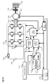
- FIG. 1 is a circuit configuration diagram of a motor control device according to the present embodiment.
- the battery 101 is a nickel metal hydride battery or a lithium ion battery.
- the contactor 102 is disposed between the battery 101 and the inverter 104. When the contactor 102 is off, the battery 101 and the inverter 104 are electrically disconnected. When the contactor 102 is on, the battery 101 and the inverter 104 are electrically connected, and the power of the battery 101 is supplied to the inverter 104. Smoothing capacitor 103 smoothes the input voltage of inverter 104.
- the inverter 104 includes U-phase, V-phase, and W-phase upper and lower arms in which a switching element called an upper arm and a switching element called a lower arm are connected in series.
- Inverter 104 has a DC side connected to smoothing capacitor 103 and a three-phase AC side connected to a stator of motor 106.
- the phase current detector 105 is connected to the UVW phase between the AC side of the inverter 104 and the motor 106, and detects the UVW phase current.
- the motor 106 is an AC motor that generates a cranking torque after receiving a cranking torque command.
- the motor 106 is connected to a drive shaft of the vehicle via a second clutch (not shown), and it is possible to generate a driving force for driving the vehicle by rotating the drive shaft.
- the angle sensor 107 detects the rotor angle of the motor 106 and is, for example, a resolver or a magnetic sensor. In the present embodiment, the angle sensor 107 that may cause a detection error due to a mounting offset value, product variation, or the like may be used.
- the angle sensor 107 transmits the detected electrical angle value of the motor 106 based on the detected rotor angle of the motor 106.
- the clutch 108 is disposed between the motor 106 and the engine 109. When the clutch 108 is off, the motor 106 and the engine 109 are mechanically disconnected. When the clutch 108 is on, the motor 106 and the engine 109 are mechanically connected. The clutch 108 is turned on when the engine 109 needs to be started immediately after the ignition key is turned on, or when the engine 109 is stopped and the vehicle is running with only the driving force of the motor 106. Then, the motor 106 cranks the engine 109. The engine 109 generates driving force that causes the vehicle to travel.
- the vehicle controller 110 is a host controller that transmits a cranking torque command value TQ1 when the torque control mode 113 is valid. Further, the vehicle controller 110 transmits an angle error automatic adjustment mode transition command after the rotational speed of the motor 106 becomes larger than the minimum speed necessary for the adjustment mode.
- the torque control mode 113 is a mode setting unit that transmits a torque control validation flag to the current command calculation unit 111.
- the rotation speed control mode 114 is a mode setting unit that transmits a rotation speed control validation flag to the current command calculation unit 111.
- the current command calculation unit 111 is a calculation unit that calculates a current command and a current phase command.
- the current command calculation unit 111 receives a fixed current command value and a fixed current phase angle command based on the cranking torque command value TQ1 from the vehicle controller 110 when the torque control mode 113 validation flag is received. The value is calculated and output to the current control unit 112.
- the current command calculation unit 111 calculates the difference between the rotation speed command value S2 and the motor rotation speed S1 by PI control when the rotation speed control mode 114 validation flag is received, and the current command value and current depending on the speed difference
- the phase angle command value is output to the current control unit 112.
- the current control unit 112 includes a current command from the current command calculation unit 111, a current phase angle command value, a UVW phase current detection value from the phase current detector 105, a motor rotor angle information from the phase correction unit 116, and an angle error.
- a PWM signal is generated based on the correction value.
- the inverter 104 is driven by this PWM signal.
- the mode switching control unit 115 is a control unit that determines the timing for switching from the torque control mode 113 to the rotational speed control mode 114 when the motor rotational speed S1 does not reach the predetermined speed within the first predetermined time.
- the mode switching control unit 115 is a control unit that determines whether the rotation direction of the motor 106 is the forward rotation direction or the reverse rotation direction, and determines the timing for switching from the torque control mode 113 to the rotation speed control mode 114. .
- a switching signal is output to the selector switch 115S.
- the mode switching control unit 115 calculates the phase correction permission flag F1 when the motor rotational speed S1 does not reach the predetermined speed within the second predetermined time, and sets this flag as the phase. It transmits to the correction
- the rotor angle of the motor 106 detected by the angle sensor 107 is input to the phase correction unit 116.
- the phase correction unit 116 calculates the motor rotation speed S ⁇ b> 1 based on the input rotor angle of the motor 106. Then, the phase correction unit 116 calculates an angle error correction value based on the calculated motor rotation speed S1, the rotation speed command value S2 input from the mode switching control unit 115, and the phase correction permission flag F1.
- the angle error control unit 117 adjusts the angle error of the angle sensor 107 based on the detected UVW phase current value and the motor rotor angle information according to the angle error automatic adjustment mode transition command from the vehicle controller 110.
- the method of adjusting the angle error is a general method of passing a current through the motor 106 and comparing the difference in current phase between when there is an angle error and when there is no error.
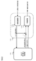
- FIG. 2 is a circuit configuration diagram of the phase correction unit 116.
- the phase correction unit 116 receives the detected angle value of the rotor of the motor 106 from the angle sensor 107, and calculates the motor rotation speed S1 by the speed calculation unit 116a.
- the mode switching control unit 115 switches from the torque control mode 113 to the rotational speed control mode 114 when the motor rotational speed S1 does not reach the predetermined speed within the first predetermined time. A case where the engine 109 can be cranked after switching to the rotation speed control mode 114 will be described later with reference to FIG.
- the mode switching control unit 115 turns on the phase correction permission flag F1 and performs PI control.
- the PI control unit 116b receives the phase correction permission flag F1, it calculates the angle error correction value by calculating the difference between the rotation speed command value S2 and the motor rotation speed S1.
- the calculated angle error correction value is input to the current command calculation unit 111 and the current control unit 112. Details thereof will be described later with reference to FIG.
- the current command calculation unit 111 After switching to the rotation speed control mode 114, the current command calculation unit 111 outputs, for example, 45 [deg] as the current phase angle command value. At this time, if the angle error is 45 [deg], the actual current phase angle ⁇ is 90 [deg]. In this case, the motor torque becomes substantially zero by the following equation (1).
- ⁇ is an interlinkage magnetic flux
- Pn is the number of pole pairs
- Ld and Lq are motor inductances
- Ia is a UVW phase current effective value
- ⁇ is a current phase angle.
- Equation (1) the angle error correction value is added to the electrical angle detection value of the motor 106 to obtain Equation (2), thereby avoiding that the actual current phase angle ⁇ is 90 [deg]. it can.
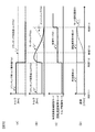
- FIG. 3 is a time chart showing the time transition of the mode switching control in Case 1.
- 3A shows the torque command value for cranking
- FIG. 3B shows the motor torque
- FIG. 3C shows the control mode
- FIG. 3D shows the rotation speed of the motor 106. Show.
- the torque command value for cranking TQ1 shown in FIG. 3A is a torque command value for cranking the engine 109 from the vehicle controller 110.
- the minimum cranking torque TQ2 is the minimum torque necessary to drive and rotate the engine 109 from the outside.
- a motor torque TQ3 shown in FIG. 3B is a shaft torque generated in the motor 106.
- the engine torque TQ4 is a shaft torque generated in the engine 109.
- the control mode M1 shown in FIG. 3C is a torque control mode 113, a rotation speed control mode 114, an angle error automatic adjustment mode, or the like.
- the motor rotation speed S1 shown in FIG. 3D cannot be increased when the motor torque TQ3 is smaller than the minimum cranking torque TQ2.
- the rotation speed command value S2 is a speed command value of the motor 106 that is output from the mode switching control unit 115 so that the angle error control unit 117 performs angle error adjustment of the angle sensor 107.
- the predetermined speed S3 is a speed necessary for the angle error control unit 117 to execute the angle error adjustment of the angle sensor 107, and is equal to or smaller than the rotational speed command value S2.
- the motor control device can adjust the angle error of the angle sensor 107 in response to the cranking torque command TQ1 transmitted from the vehicle controller 110 at a predetermined timing.
- the angle sensor 107 receives a cranking torque command immediately after the ignition key is turned on immediately after the motor 106 is incorporated into the drive system or when the accelerator is operated, or immediately after the ignition key is turned on or immediately after the motor 106 is replaced. The angle error is adjusted.
- the vehicle controller 110 transmits a cranking torque command value TQ1 to the current command calculation unit 111.
- the control mode M1 is in the torque control mode 113.
- the motor torque TQ3 cannot be equal to the cranking torque command value TQ1 due to an angle error, and is smaller than the minimum cranking torque TQ2. Therefore, the motor 106 cannot crank the engine 109. At this time, the motor rotation speed S1 cannot be increased.
- the motor rotation speed S1 does not increase, at time T12, the motor rotation speed S1 does not reach the predetermined speed S3 within the first predetermined time (time from time T11 to time T12).
- the control mode M1 is switched from the torque control mode 113 to the rotation speed control mode 114.
- the motor torque TQ3 increases rapidly because the difference between the motor rotation speed S1 and the rotation speed command value S2 is large.
- the motor rotation speed S1 increases because the motor torque TQ3 is greater than the minimum cranking torque TQ2.
- the motor rotation speed S1 reaches the cranking speed (for example, 100 rpm)
- the engine 109 can be cranked.
- the motor torque TQ3 decreases because the difference between the motor rotation speed S1 and the rotation speed command value S2 gradually decreases.
- the engine torque TQ4 gradually increases due to the cranking of the engine 109.
- the motor rotation speed S1 is increased by the driving force generated by the engine 109.
- the mode shifts to the angle error automatic adjustment mode.
- an angle error automatic adjustment mode transition command is transmitted from the vehicle controller 110 to the angle error control unit 117. Then, the angle error control unit 117 adjusts the angle error of the angle sensor 107.
- the torque control mode 113 is switched to the rotation speed control mode 114. Then, a current command and a current phase command are calculated based on the motor rotation speed S1 and the rotation speed command value S2. Thereby, it is possible to successfully crank the engine 109 and increase the motor rotation speed S1.
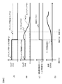
- FIG. 4 is a time chart showing the time transition of the mode switching control in Case 2.
- 4A shows the torque command value for cranking
- FIG. 4B shows the motor torque
- FIG. 4C shows the control mode
- FIG. 4D shows the rotation speed of the motor 106. Show.
- a reverse rotation determination threshold value S4 shown in FIG. 4D is a threshold value for determining that the rotation direction of the motor 106 is the reverse rotation direction.
- the vehicle controller 110 transmits the cranking torque command value TQ1 to the current command calculation unit 111.
- the control mode M1 is in the torque control mode 113.
- the sum of the current phase angle command value and the angle error becomes negative, so that the motor torque TQ3 becomes negative as shown in FIG. 4B.
- the motor rotation speed S1 decreases in the minus direction.
- the mode switching control unit 115 determines the reverse rotation direction.
- the control mode M1 is switched from the torque control mode 113 to the rotation speed control mode 114.
- the motor torque TQ3 increases rapidly because the difference between the motor rotation speed S1 and the rotation speed command value S2 is large.
- the motor rotation speed S1 increases because the motor torque TQ3 is greater than the minimum cranking torque TQ2.
- the engine 109 can be cranked.
- the motor torque TQ3 decreases because the difference between the motor rotation speed S1 and the rotation speed command value S2 gradually decreases.
- the engine torque TQ4 gradually increases due to the cranking of the engine 109.
- the motor rotation speed S1 is increased by the driving force generated by the engine 109.
- the timing for switching from the torque control mode 113 to the rotation speed control mode 114 is changed based on the rotation direction when the motor 106 starts rotating.
- the torque control mode 113 is switched to the rotation speed control mode 114.
- the torque control mode 113 is switched to the rotation speed control mode 114.
- FIG. 5 is a time chart showing the time transition of the mode switching control in Case 3.
- 5A shows the torque command value for cranking
- FIG. 5B shows the motor torque
- FIG. 5C shows the control mode
- FIG. 5D shows the rotation speed of the motor 106. Show.
- the vehicle controller 110 transmits the cranking torque command value TQ1 to the current command calculation unit 111.
- the control mode M1 is in the torque control mode 113.
- the motor torque TQ3 is approximately the same as the cranking minimum torque TQ2.
- the motor rotation speed S1 gradually increases.
- the engine 109 can be cranked.
- the motor torque TQ3 decreases because the difference between the motor rotation speed S1 and the rotation speed command value S2 gradually decreases.
- the engine torque TQ4 gradually increases due to the cranking of the engine 109.
- the motor rotation speed S1 is increased by the driving force generated by the engine 109.
- FIG. 6 is a time chart showing the time transition of the mode switching control in Case 4.
- 6A shows the torque command value for cranking
- FIG. 6B shows the angle error correction value
- FIG. 6C shows the phase correction permission flag
- FIG. 6D shows the control mode.
- FIG. 6E shows the rotational speed of the motor 106.
- An angle error correction value H1 shown in FIG. 6B is a correction value added to the electrical angle detection value of the motor 106.
- the angle error correction value H1 is obtained by calculating the difference between the rotation speed command value S2 and the motor rotation speed S1 by the PI control unit 116b.
- the detected electrical angle value of the motor 106 is the same as the detected angle value of the rotor.
- the phase correction permission flag F1 shown in FIG. 6C is calculated by the mode switching control unit 115. When the phase correction permission flag F1 is on, the phase correction unit 116 calculates the angle error correction value H1.
- the vehicle controller 110 transmits the cranking torque command value TQ1 to the current command calculation unit 111.
- the control mode M1 is in the torque control mode 113.
- the motor torque TQ3 is smaller than the minimum cranking torque TQ2. Therefore, the motor 106 cannot crank the engine 109. At this time, the motor rotation speed S1 cannot be increased.
- the motor rotation speed S1 does not increase, at time T42, the motor rotation speed S1 does not reach the predetermined speed S3 within the first predetermined time (from time T41 to time T42).
- the control mode M1 is switched from the torque control mode 113 to the rotation speed control mode 114.
- the motor torque TQ3 is larger than the value at time T41, the motor 106 cannot crank the engine 109 because it does not reach the cranking minimum torque TQ2. At this time, the motor rotation speed S1 cannot be increased.
- the engine 109 can be cranked.
- the angle error correction value H1 decreases because the difference between the motor rotation speed S1 and the rotation speed command value S2 gradually decreases.
- the motor torque TQ3 decreases because the difference between the motor rotation speed S1 and the rotation speed command value S2 gradually decreases.
- the motor rotation speed S1 is increased by the driving force generated by the engine 109.
- the mode switching control unit 115 determines that the motor rotational speed S1 does not reach the predetermined speed S3 within the second predetermined time after switching to the rotational speed control mode 114, the mode switching control unit 115 calculates the rotational speed command value S2. It transmits to the correction
- the PI control unit 116b of the phase correction unit 116 calculates the angle error correction value H1 by calculating the difference between the rotation speed command value S2 and the motor rotation speed S1. Further, the current phase is controlled by adding the angle error correction value H1 to the motor electrical angle detection value.
- the motor torque may be substantially zero even if the rotational speed control mode 114 is switched, and the engine 109 may not be cranked. there were. According to the present embodiment, even if the current phase is approximately 90 [deg], the engine 109 can be cranked and the motor rotation speed can be increased.
- FIG. 7 is a diagram for explaining angle error automatic adjustment in the prior art.
- the engine 109 is cranked by the motor 106 under the control of the torque control mode, and the motor 109 increases the motor rotation speed.
- the angle error automatic adjustment mode of the angle sensor 107 is performed.
- the angle error automatic adjustment mode is terminated.
- the method for adjusting the angle error is a general method in which a current is passed through the motor 106 and the difference between the current phase angles when there is an angle error and when there is no error is compared.
- cranking torque command value TQ1 is made constant in the torque control mode 113.
- the current command calculation unit 111 receives the cranking torque command value TQ1 from the vehicle controller 110, and calculates a specific UVW phase current command value and a current phase angle command value. When there is an angle error in the angle sensor 107, a deviation occurs between the current phase angle command value and the actual current phase ⁇ , and it may not be possible to output a desired cranking torque and to increase the motor rotation speed.
- the motor control device is a motor control device used in a drive system including an engine 109 and a motor 106 having an angle sensor 107 that detects angle information of the rotor. Based on the rotation operation of the motor 106 after receiving the cranking torque command for cranking 109, the motor 106 is controlled by switching from the torque control mode to the rotation speed control mode, and the rotation speed of the motor 106 is set to a predetermined value. The speed is increased to the speed, and the angle error adjustment of the angle sensor 107 is executed. Thereby, the engine can be cranked and the rotational speed of the motor can be increased.
- the present invention is not limited to the above-described embodiment, and other forms conceivable within the scope of the technical idea of the present invention are also included in the scope of the present invention as long as the characteristics of the present invention are not impaired. .
Landscapes
- Engineering & Computer Science (AREA)
- Mechanical Engineering (AREA)
- Transportation (AREA)
- Chemical & Material Sciences (AREA)
- Combustion & Propulsion (AREA)
- Power Engineering (AREA)
- General Engineering & Computer Science (AREA)
- Health & Medical Sciences (AREA)
- Biomedical Technology (AREA)
- General Health & Medical Sciences (AREA)
- Automation & Control Theory (AREA)
- Electric Propulsion And Braking For Vehicles (AREA)
- Control Of Electric Motors In General (AREA)
- Hybrid Electric Vehicles (AREA)
Abstract
所望のクランキングトルクを出力できず、モータの回転速度を上昇させることができない。 モータ制御装置は、エンジンと、回転子の角度情報を検出する角度センサを有するモータと、を備える駆動システムに用いられるモータ制御装置であって、モータを駆動してエンジンをクランキングするためのクランキング用トルク指令を受信した後のモータの回転動作に基づいて、モータをトルク制御モードから回転速度制御モードに切り替えて制御し、モータの回転速度を所定速度まで上昇させ、角度センサの角度誤差調整を実行する。
Description
本発明は、モータ制御装置に関する。
エンジンを搭載した車両において、エンジンを始動するためにモータが用いられる。モータには角度センサが設けられ、モータの回転子角度を検出している。
従来では、クランキングのための目標トルク指令に従ってモータが駆動されることにより、エンジンがクランキングされてエンジン回転数が上昇する(特許文献1)。この場合、モータを駆動してエンジンと連結するためのクランキング用の目標トルク指令は一定値である。
上述した、特許文献1に記載の方法では、角度センサに角度誤差が有る場合、所望のクランキングトルクを出力できず、モータの回転速度を上昇させることができない。
本発明によるモータ制御装置は、エンジンと、回転子の角度情報を検出する角度センサを有するモータと、を備える駆動システムに用いられるモータ制御装置であって、モータを駆動してエンジンをクランキングするためのクランキング用トルク指令を受信した後のモータの回転動作に基づいて、モータをトルク制御モードから回転速度制御モードに切り替えて制御し、モータの回転速度を所定速度まで上昇させ、角度センサの角度誤差調整を実行する。
本発明によれば、エンジンをクランキングして、モータの回転速度を上昇することができる。
図1は、本実施形態に係るモータ制御装置の回路構成図である。
バッテリ101は、ニッケル水素バッテリやリチウムイオンバッテリなどが用いられる。コンタクタ102は、バッテリ101とインバータ104の間に配置され、コンタクタ102がオフの時、バッテリ101とインバータ104は電気的に遮断される。コンタクタ102がオンの時バッテリ101とインバータ104は電気的に接続され、バッテリ101の電力がインバータ104に供給される。平滑キャパシタ103は、インバータ104の入力電圧を平滑化する。
バッテリ101は、ニッケル水素バッテリやリチウムイオンバッテリなどが用いられる。コンタクタ102は、バッテリ101とインバータ104の間に配置され、コンタクタ102がオフの時、バッテリ101とインバータ104は電気的に遮断される。コンタクタ102がオンの時バッテリ101とインバータ104は電気的に接続され、バッテリ101の電力がインバータ104に供給される。平滑キャパシタ103は、インバータ104の入力電圧を平滑化する。
インバータ104は、上アームと呼ばれるスイッチング素子と、下アームと呼ばれるスイッチング素子とを上下直列に接続した、U相、V相、W相の上下アームにより構成される。インバータ104は、直流側が平滑キャパシタ103に接続され、3相交流側はモータ106の固定子に接続される。相電流検出器105は、インバータ104の交流側とモータ106の間のUVW相に接続され、UVW相電流を検出する。モータ106は、クランキング用トルク指令を受信した後、クランキング用トルクを発生させる交流モータである。また、モータ106は不図示の第2クラッチを介して車両の駆動軸に接続されており、この駆動軸を回転駆動させて車両を走行させる駆動力を発生することもできる。角度センサ107は、モータ106の回転子角度を検出し、例えばレゾルバ、磁気センサなどである。本実施形態では、角度センサ107は、取付オフセット値、製品のばらつき等により検出誤差が生じる可能性があるものを用いてもよい。角度センサ107は、検出したモータ106の回転子角度に基づいて、モータ106の電気角検出値を送信する。
クラッチ108は、モータ106とエンジン109の間に配置される。クラッチ108がオフの時、モータ106とエンジン109は機械的に遮断され、クラッチ108がオンの時、モータ106とエンジン109は機械的に接続される。イグニションキーのオン直後や、エンジン109が停止しておりモータ106の駆動力のみで車両が走行している状態でのアクセル動作時など、エンジン109を始動させる必要がある時には、クラッチ108がオンにされてモータ106はエンジン109をクランキングする。エンジン109は、車両を走行させる駆動力を発生させる。
車両コントローラ110は、トルク制御モード113が有効である時に、クランキング用トルク指令値TQ1を送信する上位コントローラである。さらに、車両コントローラ110は、モータ106の回転速度が調整モードに必要な最低速度より大きくなった後に、角度誤差自動調整モード遷移指令を送信する。
トルク制御モード113は、電流指令演算部111にトルク制御の有効化フラグを送信するモード設定部である。回転速度制御モード114は、電流指令演算部111に回転速度制御の有効化フラグを送信するモード設定部である。
電流指令演算部111は、電流指令と電流位相指令を演算する演算部である。電流指令演算部111は、トルク制御モード113の有効化フラグを受信した時に、車両コントローラ110からのクランキング用トルク指令値TQ1に基づいて、固定的な電流指令値と固定的な電流位相角指令値を演算して電流制御部112に出力する。電流指令演算部111は、回転速度制御モード114の有効化フラグを受信した時に、回転速度指令値S2とモータ回転速度S1の差分をPI制御で演算し、速度差分に依存する電流指令値と電流位相角指令値を電流制御部112に出力する。
電流制御部112は、電流指令演算部111からの電流指令、電流位相角指令値と、相電流検出器105からのUVW相電流検出値、位相補正部116からのモータ回転子角度情報、角度誤差補正値とに基づいて、PWM信号を生成する。このPWM信号によりインバータ104を駆動する。
モード切り替え制御部115は、モータ回転速度S1が第1所定時間内に所定速度に達しない場合、トルク制御モード113から回転速度制御モード114に切り替えるタイミングを判断する制御部である。また、モード切り替え制御部115は、モータ106の回転方向が正回転方向と逆転方向のいずれであるかを判定し、トルク制御モード113から回転速度制御モード114に切り替えるタイミングを判断する制御部である。切り替えるタイミングでは、切替信号を切替スイッチ115Sへ出力する。さらに、モード切り替え制御部115は、回転速度制御モード114に切り替えた後、モータ回転速度S1が第2所定時間内に所定速度に達しない場合、位相補正許可フラグF1を算出し、このフラグを位相補正部116に送信する。
位相補正部116には、角度センサ107で検出されたモータ106の回転子角度が入力される。位相補正部116は、入力されたモータ106の回転子角度に基づいてモータ回転速度S1を算出する。そして、位相補正部116は、算出したモータ回転速度S1と、モード切り替え制御部115より入力された回転速度指令値S2および位相補正許可フラグF1に基づいて角度誤差補正値を算出する。
角度誤差制御部117は、車両コントローラ110からの角度誤差自動調整モード遷移指令に応じて、UVW相電流検出値、モータ回転子角度情報に基づいて、角度センサ107の角度誤差を調整する。角度誤差を調整する方法は、モータ106に電流を流して、角度誤差が有る時と誤差無い時の電流位相の差分を比較する一般的な方法である。
図2は、位相補正部116の回路構成図である。
位相補正部116は、角度センサ107からモータ106の回転子の角度検出値を入力し、速度演算部116aでモータ回転速度S1を算出する。モード切り替え制御部115は、モータ回転速度S1が第1所定時間内に所定速度に達しない場合、トルク制御モード113から回転速度制御モード114に切り替える。回転速度制御モード114に切り替えた後に、エンジン109をクランキングできる場合については、図3を用いて後述する。
位相補正部116は、角度センサ107からモータ106の回転子の角度検出値を入力し、速度演算部116aでモータ回転速度S1を算出する。モード切り替え制御部115は、モータ回転速度S1が第1所定時間内に所定速度に達しない場合、トルク制御モード113から回転速度制御モード114に切り替える。回転速度制御モード114に切り替えた後に、エンジン109をクランキングできる場合については、図3を用いて後述する。
回転速度制御モード114に切り替えた後、モータ回転速度S1が第2所定時間内に所定速度に達しないと判定した場合、モード切り替え制御部115は、位相補正許可フラグF1をオンにして、PI制御部116bに送信する。PI制御部116bにおいて、位相補正許可フラグF1を受信した場合、回転速度指令値S2とモータ回転速度S1の差分を演算して角度誤差補正値を算出する。算出された角度誤差補正値は電流指令演算部111と電流制御部112に入力される。その詳細については、図6を用いて後述する。
一例として角度誤差補正値に基づく制御について説明する。回転速度制御モード114に切り替えた後、電流指令演算部111は、電流位相角指令値として例えば45[deg]を出力する。このとき、仮に角度誤差が45[deg]にある場合、実際の電流位相角βが90[deg]になる。この場合、下記の式(1)によりモータトルクが略ゼロになる。

ここで、Φは鎖交磁束、Pnは極対数、Ld,Lqはモータのインダクタンスであり、IaはUVW相電流実効値、βは電流位相角である。
式(1)において、角度誤差補正値をモータ106の電気角検出値に加算して、式(2)とすることにより、実際の電流位相角βが90[deg]になることを避けることができる。

図3は、ケース1におけるモード切り替え制御の時間推移を示すタイムチャートである。図3(A)は、クランキング用トルク指令値を、図3(B)は、モータトルクを、図3(C)は、制御モードを、図3(D)は、モータ106の回転速度を示す。
図3(A)に示すクランキング用トルク指令値TQ1は、車両コントローラ110からエンジン109をクランキングするトルク指令値である。クランキング用最低トルクTQ2は、エンジン109を外部から駆動して回転させるのに必要な最低トルクである。
図3(B)に示すモータトルクTQ3は、モータ106に発生するシャフトトルクである。エンジントルクTQ4は、エンジン109に発生するシャフトトルクである。
図3(C)に示す制御モードM1は、トルク制御モード113、回転速度制御モード114、または角度誤差自動調整モードなどである。
図3(C)に示す制御モードM1は、トルク制御モード113、回転速度制御モード114、または角度誤差自動調整モードなどである。
図3(D)に示すモータ回転速度S1は、モータトルクTQ3がクランキング用最低トルクTQ2より小さい場合、上昇できない。回転速度指令値S2は、角度誤差制御部117において角度センサ107の角度誤差調整を実行するためにモード切り替え制御部115から出力されるモータ106の速度指令値である。所定速度S3は、角度誤差制御部117において角度センサ107の角度誤差調整を実行するために必要な速度であり、回転速度指令値S2と等しいか、回転速度指令値S2よりも小さい。
なお、本実施形態に係るモータ制御装置では、所定のタイミングで車両コントローラ110から送信されるクランキング用トルク指令TQ1を受けて、角度センサ107の角度誤差調整を実施することができる。例えば、モータ106が駆動システムに組み込まれた直後のイグニションキーオン直後またはアクセル動作時、またはモータ106が交換された直後のイグニションキーオン直後またはアクセル動作時に、クランキング用トルク指令を受けて、角度センサ107の角度誤差調整を実施する。
図3(A)~(D)に示す時刻T11において、車両コントローラ110はクランキング用トルク指令値TQ1を電流指令演算部111に送信する。この時、制御モードM1は、トルク制御モード113にある。また、図3に示すケース1では、モータトルクTQ3は、角度誤差によって、クランキング用トルク指令値TQ1と同等のトルクを出せず、クランキング用最低トルクTQ2より小さいとする。そのため、モータ106がエンジン109をクランキングできない。この時、モータ回転速度S1は、上昇できない。
モータ回転速度S1が上昇しないため、時刻T12において、モータ回転速度S1が第1所定時間(時刻T11から時刻T12までの時間)内に所定速度S3に達しない。この時、制御モードM1は、トルク制御モード113から回転速度制御モード114に切り替える。この時、モータトルクTQ3は、モータ回転速度S1と回転速度指令値S2の差分が大きいため、急激に上昇して行く。そして、モータ回転速度S1は、モータトルクTQ3がクランキング用最低トルクTQ2より大きくなるため上昇する。
時刻T13において、モータ回転速度S1がクランキングスピード(例えば100rpm)に達すると、エンジン109をクランキングできる。この時、モータトルクTQ3は、モータ回転速度S1と回転速度指令値S2の差分が徐々に小さくなるため、減少して行く。そして、エンジントルクTQ4は、エンジン109をクランキングできたことにより、徐々に上昇する。この時、モータ回転速度S1は、エンジン109が発生する駆動力により上昇される。
時刻T14において、モータ回転速度S1が所定速度S3に達すると、角度誤差自動調整モードに遷移する。この時、車両コントローラ110から角度誤差自動調整モード遷移指令を角度誤差制御部117へ送信する。そして、角度誤差制御部117は、角度センサ107の角度誤差を調整する。
本実施形態によれば、クランキング用トルク指令を受信したのち、モータ回転速度S1が所定時間内に所定速度に達しない場合、トルク制御モード113から回転速度制御モード114に切り替える。そして、モータ回転速度S1と回転速度指令値S2に基づいて電流指令と電流位相指令を演算する。これにより、エンジン109をクランキングすることに成功し、モータ回転速度S1を上昇することができる。
図4は、ケース2におけるモード切り替え制御の時間推移を示すタイムチャートである。図4(A)は、クランキング用トルク指令値を、図4(B)は、モータトルクを、図4(C)は、制御モードを、図4(D)は、モータ106の回転速度を示す。
電流位相角指令値と角度誤差の和βがマイナスになる場合、式(1)によりモータトルクがマイナスになり、モータ106の回転方向が逆転する可能性がある。ケース2ではこの場合を示す。図4(D)に示す逆転判定閾値S4は、モータ106の回転方向が逆転方向と判定する閾値である。
時刻T21において、車両コントローラ110はクランキング用トルク指令値TQ1を電流指令演算部111に送信する。この時、制御モードM1は、トルク制御モード113にある。図4に示すケース2では、電流位相角指令値と角度誤差の和がマイナスになることにより、図4(B)に示すようにモータトルクTQ3がマイナスになる。この時、モータ回転速度S1は、マイナス方向に低下する。
時刻T22において、モータ回転速度S1が逆転判定閾値S4より低下すると、モード切り替え制御部115は逆転方向と判定する。この時、制御モードM1は、トルク制御モード113から回転速度制御モード114に切り替える。モータトルクTQ3は、モータ回転速度S1と回転速度指令値S2の差分が大きいため、急激に上昇して行く。そして、モータ回転速度S1は、モータトルクTQ3がクランキング用最低トルクTQ2より大きくなるため上昇する。
時刻T23において、モータ回転速度S1がクランキングスピードに達すると、エンジン109をクランキングできる。この時、モータトルクTQ3は、モータ回転速度S1と回転速度指令値S2の差分が徐々に小さくなるため、減少していく。また、エンジントルクTQ4は、エンジン109をクランキングできたことにより、徐々に上昇する。この時、モータ回転速度S1は、エンジン109が発生する駆動力により上昇される。
一般に、反対方向トルクまたは0トルク出力では、所定時間内に所定の回転速度に達しない場合がある。角度センサ107に角度誤差が有る場合、電流位相βにズレが発生し、所望のクランキングトルクを出力できず、モータ106の回転速度を上昇させることができない可能性がある。この場合、モータ106がロック状態で長い時間モータ106に電流が流れると、モータ106の巻線が焼損する可能性がある。
さらに、角度センサ107の角度誤差が大きい場合、クランキング用トルク指令値TQ1と逆方向のモータトルクが発生する可能性もある。これにより、エンジン109をクランキングすることが成功しても、クランキング用トルク指令値TQ1をエンジン109のトルクと逆方向にしているため、回転速度の上昇に支障が発生する可能性がある。最悪の場合、モータ106が逆転する可能性がある。
本実施形態では、モータ106の回転始動時の回転方向に基づいて、トルク制御モード113から回転速度制御モード114に切り替えるタイミングが変わる。モータ106の回転方向が逆転方向である場合には、トルク制御モード113から回転速度制御モード114に切り替える。さらに、モータ106が停止または正転方向であって所定時間内に所定速度に達しない場合には、トルク制御モード113から回転速度制御モード114に切り替える。モータ106が逆転或いは、正転しても所定時間内に所定速度に達しないことが判った時点で、制御モードを回転速度制御モード114に切り替えることで、所定回転速度になる時間を短縮できる。
図5は、ケース3におけるモード切り替え制御の時間推移を示すタイムチャートである。図5(A)は、クランキング用トルク指令値を、図5(B)は、モータトルクを、図5(C)は、制御モードを、図5(D)は、モータ106の回転速度を示す。
時刻T31において、車両コントローラ110はクランキング用トルク指令値TQ1を電流指令演算部111に送信する。この時、制御モードM1は、トルク制御モード113にある。そして、モータトルクTQ3は、クランキング用最低トルクTQ2とほぼ同じ大きさにある。この時、モータ回転速度S1は、徐々に上昇する。
図5に示すケース3では、時刻T32において、モータ回転速度S1が第1所定時間(時刻T31から時刻T32までの時間)内に所定速度S3に達しないとする。この時、制御モードM1は、トルク制御モード113から回転速度制御モード114に切り替える。そして、モータトルクTQ3は、モータ回転速度S1と回転速度指令値S2の差分が大きいため、急激に上昇して行く。この時、モータ回転速度S1は、モータトルクTQ3がクランキング用最低トルクTQ2より大きくなるため上昇する。
時刻T33において、モータ回転速度S1がクランキングスピードに達すると、エンジン109をクランキングできる。この時、モータトルクTQ3は、モータ回転速度S1と回転速度指令値S2の差分が徐々に小さくなるため、減少して行く。エンジントルクTQ4は、エンジン109をクランキングできたことにより、徐々に上昇する。この時、モータ回転速度S1は、エンジン109が発生する駆動力により上昇される。
図6は、ケース4におけるモード切り替え制御の時間推移を示すタイムチャートである。図6(A)は、クランキング用トルク指令値を、図6(B)は、角度誤差補正値を、図6(C)は、位相補正許可フラグを、図6(D)は、制御モードを、図6(E)は、モータ106の回転速度を示す。
図6(B)に示す角度誤差補正値H1は、モータ106の電気角検出値に加算する補正値である。角度誤差補正値H1は、回転速度指令値S2とモータ回転速度S1の差分をPI制御部116bで演算することにより求められる。モータ106の電気角検出値は回転子の角度検出値と同じである。
図6(C)に示す位相補正許可フラグF1は、モード切り替え制御部115で計算される。位相補正許可フラグF1がオンの時、位相補正部116で角度誤差補正値H1が算出される。
図6(C)に示す位相補正許可フラグF1は、モード切り替え制御部115で計算される。位相補正許可フラグF1がオンの時、位相補正部116で角度誤差補正値H1が算出される。
時刻T41において、車両コントローラ110はクランキング用トルク指令値TQ1を電流指令演算部111に送信する。この時、制御モードM1は、トルク制御モード113にある。図6に示すケース4では、モータトルクTQ3は、クランキング用最低トルクTQ2より小さいとする。そのため、モータ106がエンジン109をクランキングできない。この時、モータ回転速度S1は、上昇できない。
モータ回転速度S1が上昇しないため、時刻T42において、モータ回転速度S1が第1所定時間(時刻T41から時刻T42まで)内に所定速度S3に達しない。この時、制御モードM1は、トルク制御モード113から回転速度制御モード114に切り替える。モータトルクTQ3は、時刻T41時の値より大きくなったが、クランキング用最低トルクTQ2に達しないため、モータ106がエンジン109をクランキングできない。この時、モータ回転速度S1は、上昇できない。
図6に示すケース4では、回転速度制御モード114に切り替えた後、時刻T43において、モータ回転速度S1が第2所定時間(時刻T42から時刻T43まで)内に所定速度S3に達しないとする。この時に、位相補正許可フラグF1は、ONになる。そして、角度誤差補正値H1は、回転速度指令値S2とモータ回転速度S1の差分をPI制御部116bで演算することにより、徐々に上昇する。この時、モータトルクTQ3は、モータ106の電気角検出値が変化しているため、徐々に上昇する。
時刻T44において、モータ回転速度S1がクランキングスピードに達すると、エンジン109をクランキングできる。この時に、角度誤差補正値H1は、モータ回転速度S1と回転速度指令値S2の差分が徐々に小さくなるため、減少して行く。モータトルクTQ3は、モータ回転速度S1と回転速度指令値S2の差分が徐々に小さくなるため、減少して行く。この時、モータ回転速度S1は、エンジン109が発生する駆動力により上昇される。
このケース4では、回転速度制御モード114に切り替えた後、モータ回転速度S1が第2所定時間内に所定速度S3に達しない場合、モータ106の電気角検出値に角度誤差補正値H1を加算して、モータ106の回転速度を所定速度まで上昇させる。
モード切り替え制御部115は、回転速度制御モード114に切り替えた後、モータ回転速度S1が第2所定時間内に所定速度S3に達しない場合と判定した場合、回転速度指令値S2を算出し、位相補正部116に送信する。位相補正部116のPI制御部116bにおいて、回転速度指令値S2とモータ回転速度S1の差分を演算することにより角度誤差補正値H1を算出する。さらに、角度誤差補正値H1をモータ電気角検出値に加算することによって、電流位相を制御する。
従来は、角度誤差により電流位相βが略90[deg]になる場合、たとえ回転速度制御モード114に切り替えても、モータトルクが略ゼロになり、エンジン109をクランキングすることができない可能性があった。本実施形態によれば、電流位相が略90[deg]の場合であっても、エンジン109をクランキングすることに成功し、モータ回転速度を上昇することができる。
図7は従来の技術における角度誤差自動調整を説明する図である。
時刻T01において、トルク制御モードの制御により、モータ106でエンジン109をクランキングし、エンジン109でモータ回転速度を上昇させる。時刻T02において、モータ回転速度は調整モードに必要な最低速度S0より大きくなった後、角度センサ107の角度誤差自動調整モードを実施する。時刻T03において、角度誤差自動調整モードを終了する。角度誤差を調整する方法は、モータ106に電流を流して、角度誤差が有る時と誤差無い時の電流位相角の差分を比較する一般的な方法である。
時刻T01において、トルク制御モードの制御により、モータ106でエンジン109をクランキングし、エンジン109でモータ回転速度を上昇させる。時刻T02において、モータ回転速度は調整モードに必要な最低速度S0より大きくなった後、角度センサ107の角度誤差自動調整モードを実施する。時刻T03において、角度誤差自動調整モードを終了する。角度誤差を調整する方法は、モータ106に電流を流して、角度誤差が有る時と誤差無い時の電流位相角の差分を比較する一般的な方法である。
従来技術では、クランキング用トルク指令値TQ1はトルク制御モード113で一定にしている。電流指令演算部111は、車両コントローラ110からクランキング用トルク指令値TQ1を受信し、特定なUVW相電流指令値と電流位相角指令値を演算する。角度センサ107に角度誤差が有る場合、電流位相角指令値と実際電流位相βにズレが発生し、所望のクランキングトルクを出力できず、モータ回転速度を上昇させることができない可能性がある。
以上説明した実施形態によれば、次の作用効果が得られる。
(1)モータ制御装置は、エンジン109と、回転子の角度情報を検出する角度センサ107を有するモータ106と、を備える駆動システムに用いられるモータ制御装置であって、モータ106を駆動してエンジン109をクランキングするためのクランキング用トルク指令を受信した後のモータ106の回転動作に基づいて、モータ106をトルク制御モードから回転速度制御モードに切り替えて制御し、モータ106の回転速度を所定速度まで上昇させ、角度センサ107の角度誤差調整を実行する。これにより、エンジンをクランキングして、モータの回転速度を上昇することができる。
(1)モータ制御装置は、エンジン109と、回転子の角度情報を検出する角度センサ107を有するモータ106と、を備える駆動システムに用いられるモータ制御装置であって、モータ106を駆動してエンジン109をクランキングするためのクランキング用トルク指令を受信した後のモータ106の回転動作に基づいて、モータ106をトルク制御モードから回転速度制御モードに切り替えて制御し、モータ106の回転速度を所定速度まで上昇させ、角度センサ107の角度誤差調整を実行する。これにより、エンジンをクランキングして、モータの回転速度を上昇することができる。
本発明は、上記の実施形態に限定されるものではなく、本発明の特徴を損なわない限り、本発明の技術思想の範囲内で考えられるその他の形態についても、本発明の範囲内に含まれる。
101 バッテリ
102 コンタクタ
103 平滑キャパシタ
104 インバータ
105 相電流検出器
106 モータ
107 角度センサ
108 クラッチ
109 エンジン
110 車両コントローラ
111 電流指令演算部
112 電流制御部
113 トルク制御モード
114 回転速度制御モード
115 モード切り替え制御部
116 位相補正部
117 角度誤差制御部
102 コンタクタ
103 平滑キャパシタ
104 インバータ
105 相電流検出器
106 モータ
107 角度センサ
108 クラッチ
109 エンジン
110 車両コントローラ
111 電流指令演算部
112 電流制御部
113 トルク制御モード
114 回転速度制御モード
115 モード切り替え制御部
116 位相補正部
117 角度誤差制御部
Claims (8)
- エンジンと、回転子の角度情報を検出する角度センサを有するモータと、を備える駆動システムに用いられるモータ制御装置であって、
前記モータを駆動して前記エンジンをクランキングするためのクランキング用トルク指令を受信した後の前記モータの回転動作に基づいて、前記モータをトルク制御モードから回転速度制御モードに切り替えて制御し、前記モータの回転速度を所定速度まで上昇させ、前記角度センサの角度誤差調整を実行するモータ制御装置。 - 請求項1に記載のモータ制御装置において、
前記トルク制御モードは、固定的な電流指令値と電流位相角指令値に基づいて前記モータを制御するモードであり、前記回転速度制御モードは、回転速度指令値と前記モータのモータ回転速度の差分に依存する電流指令値と電流位相角指令値に基づいて前記モータを制御するモードであるモータ制御装置。 - 請求項1または請求項2に記載のモータ制御装置において、
前記モータを前記トルク制御モードから前記回転速度制御モードに切り替えて制御する前記モータの回転動作は、前記モータのモータ回転速度が所定時間内に前記所定速度に達しない回転動作であるモータ制御装置。 - 請求項1または請求項2に記載のモータ制御装置において、
前記モータを前記トルク制御モードから前記回転速度制御モードに切り替えて制御する前記モータの回転動作は、前記モータの回転始動時の回転方向が所定方向の回転動作であるモータ制御装置。 - 請求項4に記載のモータ制御装置において、
前記モータの回転始動時の回転方向が逆転方向である場合には、前記トルク制御モードから前記回転速度制御モードに切り替えるモータ制御装置。 - 請求項5に記載のモータ制御装置において、
前記モータの回転方向が正転方向であって前記モータのモータ回転速度が所定時間内に前記所定速度に達しない場合には、前記トルク制御モードから前記回転速度制御モードに切り替えるモータ制御装置。 - 請求項1から請求項6までのいずれか一項に記載のモータ制御装置において、
前記回転速度制御モードに切り替えた後、前記モータの回転速度が第2所定時間内に前記所定速度に達しない場合、前記モータの電気角検出値に角度誤差補正値を加算して、前記モータの回転速度を前記所定速度まで上昇させるモータ制御装置。 - 請求項1から請求項7までのいずれか一項に記載のモータ制御装置において、
前記モータが前記駆動システムに組み込まれた直後のイグニションキーオン直後またはアクセル動作時、または前記モータが交換された直後のイグニションキーオン直後またはアクセル動作時に、前記クランキング用トルク指令を受信して前記角度センサの角度誤差調整を実行するモータ制御装置。
Priority Applications (1)
| Application Number | Priority Date | Filing Date | Title |
|---|---|---|---|
| JP2018547592A JP6700413B2 (ja) | 2016-10-31 | 2017-10-18 | モータ制御装置 |
Applications Claiming Priority (2)
| Application Number | Priority Date | Filing Date | Title |
|---|---|---|---|
| JP2016212449 | 2016-10-31 | ||
| JP2016-212449 | 2016-10-31 |
Publications (1)
| Publication Number | Publication Date |
|---|---|
| WO2018079359A1 true WO2018079359A1 (ja) | 2018-05-03 |
Family
ID=62024926
Family Applications (1)
| Application Number | Title | Priority Date | Filing Date |
|---|---|---|---|
| PCT/JP2017/037626 Ceased WO2018079359A1 (ja) | 2016-10-31 | 2017-10-18 | モータ制御装置 |
Country Status (2)
| Country | Link |
|---|---|
| JP (1) | JP6700413B2 (ja) |
| WO (1) | WO2018079359A1 (ja) |
Citations (4)
| Publication number | Priority date | Publication date | Assignee | Title |
|---|---|---|---|---|
| JP2008278575A (ja) * | 2007-04-26 | 2008-11-13 | Sanyo Electric Co Ltd | モータ制御装置 |
| JP2012092664A (ja) * | 2010-10-25 | 2012-05-17 | Nissan Motor Co Ltd | 車両のエンジン始動制御装置 |
| JP2013102675A (ja) * | 2011-10-17 | 2013-05-23 | Ntn Corp | 電気自動車の変速制御方法および変速制御装置 |
| JP2013138559A (ja) * | 2011-12-28 | 2013-07-11 | Bosch Corp | 同期モータに取り付けられた角度センサを較正するための方法及び装置 |
-
2017
- 2017-10-18 JP JP2018547592A patent/JP6700413B2/ja active Active
- 2017-10-18 WO PCT/JP2017/037626 patent/WO2018079359A1/ja not_active Ceased
Patent Citations (4)
| Publication number | Priority date | Publication date | Assignee | Title |
|---|---|---|---|---|
| JP2008278575A (ja) * | 2007-04-26 | 2008-11-13 | Sanyo Electric Co Ltd | モータ制御装置 |
| JP2012092664A (ja) * | 2010-10-25 | 2012-05-17 | Nissan Motor Co Ltd | 車両のエンジン始動制御装置 |
| JP2013102675A (ja) * | 2011-10-17 | 2013-05-23 | Ntn Corp | 電気自動車の変速制御方法および変速制御装置 |
| JP2013138559A (ja) * | 2011-12-28 | 2013-07-11 | Bosch Corp | 同期モータに取り付けられた角度センサを較正するための方法及び装置 |
Also Published As
| Publication number | Publication date |
|---|---|
| JP6700413B2 (ja) | 2020-05-27 |
| JPWO2018079359A1 (ja) | 2019-09-12 |
Similar Documents
| Publication | Publication Date | Title |
|---|---|---|
| CN101043196B (zh) | 同步电动机驱动装置 | |
| JP4350676B2 (ja) | ハイブリッド車両の制御装置 | |
| WO2012144276A1 (ja) | モータ制御装置 | |
| US8890451B2 (en) | Sensorless control unit for brushless DC motor | |
| JP2014204451A (ja) | 車両用発電電動機の制御装置およびその方法 | |
| US20060145652A1 (en) | Motor drive controlling device and electric power-steering device | |
| EP1320187A2 (en) | Method and system for controlling a permanent magnet machine | |
| US9130495B2 (en) | Control system for brushless motor | |
| CN100341236C (zh) | 电动机控制设备 | |
| US20150211533A1 (en) | Electric compressor | |
| WO2020137567A1 (ja) | モータ制御装置 | |
| JP6870577B2 (ja) | 回転電機の制御装置 | |
| EP2754883A1 (en) | Vehicle starting apparatus | |
| US11108347B2 (en) | Motor rotor controlling apparatus and method | |
| JP6700413B2 (ja) | モータ制御装置 | |
| CN108575112B (zh) | 用于控制电机的设备和方法 | |
| JP2009165281A (ja) | 速度センサレスベクトル制御装置 | |
| JP2006151335A (ja) | パワーステアリング装置 | |
| JP5428825B2 (ja) | モータ駆動装置 | |
| CN107733298B (zh) | 确定旋转电机旋转方向的方法和设备、汽车和程序产品 | |
| CN111106768B (zh) | 电机的启动控制方法及装置 | |
| JP2013183550A (ja) | ブラシレスモータの駆動装置 | |
| CN103684122A (zh) | 开关磁阻电机的控制方法及装置 | |
| JP2024013355A (ja) | モータ制御装置 | |
| CN109562756B (zh) | 旋转电机的故障检测装置 |
Legal Events
| Date | Code | Title | Description |
|---|---|---|---|
| 121 | Ep: the epo has been informed by wipo that ep was designated in this application |
Ref document number: 17864614 Country of ref document: EP Kind code of ref document: A1 |
|
| ENP | Entry into the national phase |
Ref document number: 2018547592 Country of ref document: JP Kind code of ref document: A |
|
| NENP | Non-entry into the national phase |
Ref country code: DE |
|
| 122 | Ep: pct application non-entry in european phase |
Ref document number: 17864614 Country of ref document: EP Kind code of ref document: A1 |