WO2018078861A1 - 画像解析システム、画像解析方法、およびプログラム - Google Patents
画像解析システム、画像解析方法、およびプログラム Download PDFInfo
- Publication number
- WO2018078861A1 WO2018078861A1 PCT/JP2016/082296 JP2016082296W WO2018078861A1 WO 2018078861 A1 WO2018078861 A1 WO 2018078861A1 JP 2016082296 W JP2016082296 W JP 2016082296W WO 2018078861 A1 WO2018078861 A1 WO 2018078861A1
- Authority
- WO
- WIPO (PCT)
- Prior art keywords
- image analysis
- imaging environment
- camera
- imaging
- environment data
- Prior art date
- Legal status (The legal status is an assumption and is not a legal conclusion. Google has not performed a legal analysis and makes no representation as to the accuracy of the status listed.)
- Ceased
Links
Images



Classifications
-
- H—ELECTRICITY
- H04—ELECTRIC COMMUNICATION TECHNIQUE
- H04N—PICTORIAL COMMUNICATION, e.g. TELEVISION
- H04N7/00—Television systems
- H04N7/18—Closed-circuit television [CCTV] systems, i.e. systems in which the video signal is not broadcast
-
- G—PHYSICS
- G06—COMPUTING OR CALCULATING; COUNTING
- G06F—ELECTRIC DIGITAL DATA PROCESSING
- G06F18/00—Pattern recognition
- G06F18/20—Analysing
- G06F18/24—Classification techniques
- G06F18/24765—Rule-based classification
-
- G—PHYSICS
- G06—COMPUTING OR CALCULATING; COUNTING
- G06T—IMAGE DATA PROCESSING OR GENERATION, IN GENERAL
- G06T7/00—Image analysis
- G06T7/70—Determining position or orientation of objects or cameras
-
- G—PHYSICS
- G06—COMPUTING OR CALCULATING; COUNTING
- G06T—IMAGE DATA PROCESSING OR GENERATION, IN GENERAL
- G06T7/00—Image analysis
- G06T7/80—Analysis of captured images to determine intrinsic or extrinsic camera parameters, i.e. camera calibration
-
- G—PHYSICS
- G06—COMPUTING OR CALCULATING; COUNTING
- G06V—IMAGE OR VIDEO RECOGNITION OR UNDERSTANDING
- G06V10/00—Arrangements for image or video recognition or understanding
- G06V10/70—Arrangements for image or video recognition or understanding using pattern recognition or machine learning
- G06V10/764—Arrangements for image or video recognition or understanding using pattern recognition or machine learning using classification, e.g. of video objects
- G06V10/765—Arrangements for image or video recognition or understanding using pattern recognition or machine learning using classification, e.g. of video objects using rules for classification or partitioning the feature space
-
- G—PHYSICS
- G06—COMPUTING OR CALCULATING; COUNTING
- G06V—IMAGE OR VIDEO RECOGNITION OR UNDERSTANDING
- G06V20/00—Scenes; Scene-specific elements
- G06V20/50—Context or environment of the image
- G06V20/52—Surveillance or monitoring of activities, e.g. for recognising suspicious objects
-
- H—ELECTRICITY
- H04—ELECTRIC COMMUNICATION TECHNIQUE
- H04N—PICTORIAL COMMUNICATION, e.g. TELEVISION
- H04N23/00—Cameras or camera modules comprising electronic image sensors; Control thereof
- H04N23/80—Camera processing pipelines; Components thereof
Definitions
- the present invention relates to an image analysis system for analyzing an image captured by a camera, an image analysis system, an image analysis method, and an image analysis method for improving detection and identification accuracy by image analysis by using parameters according to the environment in which the image is captured. And program.
- Patent Document 1 There is an image photographing device that enables the current image photographing using photographing setting information having the same content as a recorded image photographed in the past (Patent Document 1).
- Patent Document 1 it is necessary to apply shooting setting information having the same contents as the recorded image before the current shooting, and appropriate image processing cannot be performed on an already captured image.
- image analysis of a large number of images taken with unmanned aerial vehicles, wearable device cameras, security cameras, etc.
- the method of Patent Document 1 that requires the previous setting is not suitable.
- an image analysis system that analyzes an image captured by a camera, an image analysis that improves detection and identification accuracy by image analysis by using parameters that match the environment in which the image was captured. It is an object to provide a system, an image analysis method, and a program.
- the present invention provides the following solutions.
- the invention according to the first feature is Storage means for storing a plurality of imaging environment data sets composed of setting data of a camera to be imaged and data relating to a subject; Detecting means for detecting an imaging environment of the captured image from the camera; Collation means for collating the detected imaging environment with the storage means; As a result of the collation, extraction means for extracting an imaging environment data set similar to the detected imaging environment from the stored plurality of imaging environment data sets; An image analysis means for performing image analysis by applying the extracted imaging environment data set when performing image analysis of the captured image; An image analysis system is provided.
- storage means for storing a plurality of imaging environment data sets including setting data of a camera to be imaged and data relating to a subject, and the imaging environment of the captured image from the camera.
- Detection means for detecting, collating means for collating the detected imaging environment with the storage means, and imaging similar to the detected imaging environment from the plurality of stored imaging environment data sets as a result of the collation
- Extraction means for extracting an environment data set
- image analysis means for performing image analysis by applying the extracted imaging environment data set when performing image analysis of the captured image.
- the invention according to the first feature is a category of the image analysis system, but the image analysis method and the program exhibit the same actions and effects.
- the invention according to the second feature is an image analysis system which is the invention according to the first feature,
- the storage means provides an image analysis system characterized in that the imaging environment data set applied by the image analysis means is stored as a new imaging environment data set.
- the storage means replaces the imaging environment data set applied by the image analysis means with a new imaging environment data set.
- the invention according to the third feature is an image analysis system which is the invention according to the first feature or the second feature
- the imaging environment data set is an image analysis system characterized in that it is data obtained by imaging at 360 degrees.
- the imaging environment data set is data obtained by imaging at 360 degrees.
- the invention according to the fourth feature is an image analysis system which is the invention according to any one of the first feature to the third feature,
- the imaging environment data set includes an imaging angle of the camera and a distance to the subject.
- the imaging environment data set includes an imaging angle of the camera and the subject. And the distance to.
- the invention according to the fifth feature is Storing a plurality of imaging environment data sets including setting data of a camera to be imaged and data relating to a subject; Detecting an imaging environment of the captured image from the camera; Collating the detected imaging environment with the plurality of stored imaging environment data sets; As a result of the collation, extracting an imaging environment data set similar to the detected imaging environment from the stored plurality of imaging environment data sets; Applying image analysis of the extracted imaging environment data set when performing image analysis of the captured image; and
- An image analysis method characterized by comprising:
- the invention according to the sixth feature provides a computer system comprising: Storing a plurality of imaging environment data sets including setting data of a camera to be imaged and data on a subject; Detecting an imaging environment of the captured image from the camera; Collating the detected imaging environment with the stored plurality of imaging environment data sets; As a result of the collation, extracting an imaging environment data set similar to the detected imaging environment from the stored plurality of imaging environment data sets; Applying image analysis of the extracted imaging environment data set when performing image analysis of the captured image; Provide a program to execute.
- an image analysis system for analyzing an image captured by a camera
- an image analysis system and an image analysis that improve detection and identification accuracy by image analysis by using parameters according to the environment in which the image is captured.
- a method and a program can be provided.
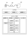
- FIG. 1 is a schematic diagram of a preferred embodiment of the present invention.
- FIG. 2 is a diagram illustrating the functional blocks of the camera 100 and the computer 200 and the relationship between the functions.
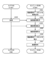
- FIG. 3 is a flowchart when the computer 200 performs image analysis processing on an image captured by the camera 100.
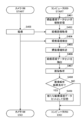
- FIG. 4 is a flowchart when the environment data set used for the image analysis processing is newly stored.
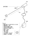
- FIG. 5 is a diagram illustrating an example when the subject 400 is imaged by the camera 100.
- FIG. 6 is a table showing an example of the data structure of the imaging environment data set.
- FIG. 7 is a table showing an example of the data structure of the imaging environment data set when the environment data set used for the image analysis processing is newly stored.
- FIG. 8 is a flowchart for storing an imaging environment data set based on actual imaging.
- FIG. 9 is a diagram for schematically explaining a method of acquiring the imaging angle of the camera 100.
- FIG. 1 is a schematic diagram of a preferred embodiment of the present invention. The outline of the present invention will be described with reference to FIG.
- the image analysis system includes a camera 100, a computer 200, and a communication network 300.
- the number of cameras 100 is not limited to one and may be plural.
- the computer 200 is not limited to a real device, and may be a virtual device.
- the camera 100 includes an imaging unit 10, a control unit 110, and a communication unit 120 as shown in FIG.
- the computer 200 includes a control unit 210, a communication unit 220, a storage unit 230, and an input / output unit 240.
- the control unit 210 implements the detection module 211 in cooperation with the communication unit 220.
- the control unit 210 implements a collation module 212, an extraction module 213, and an image analysis module 214 in cooperation with the storage unit 230.
- the storage unit 230 implements the storage module 231 in cooperation with the control unit 210.
- the communication network 300 may be a public communication network such as the Internet or a dedicated communication network, and enables communication between the camera 100 and the computer 200.
- the camera 100 is an imaging device that includes an imaging device such as an imaging element and a lens that can perform data communication with the computer 200, can measure the distance to the subject, or can simultaneously image the subject from a plurality of different directions.
- a WEB camera is illustrated as an example, but an imaging apparatus having necessary functions such as a digital camera, a digital video, a camera mounted on an unmanned aircraft, a wearable device camera, a security camera, an in-vehicle camera, and a 360-degree camera It may be.
- the computer 200 is a computing device capable of data communication with the camera 100.
- a desktop computer is illustrated as an example, but in addition to a mobile phone, a portable information terminal, a tablet terminal, a personal computer, electrical appliances such as a netbook terminal, a slate terminal, an electronic book terminal, and a portable music player Or a wearable terminal such as a smart glass or a head-mounted display.
- the computer 200 includes an imaging environment data set storage database.
- the imaging environment data set refers to environment data at the time of imaging, such as the angle from the horizontal direction of the camera at the time of imaging, the type of subject, the distance to the subject, illuminance, location, weather, camera type, resolution, etc. It is a set.
- the storage module 231 of the computer 200 associates initial values of image analysis parameters with good subject detection and identification accuracy with each of a plurality of imaging environment data sets in advance and stores them in the imaging environment data set storage database. I shall keep it.
- the imaging unit 10 of the camera 100 captures an image such as a moving image or a still image of the subject that is the object (step S01).
- the camera 100 images humans, animals, landscapes, articles, agricultural products, trees, and the like as subjects.
- the computer 200 acquires an image captured by the camera 100 via the communication unit 220 (step S02).
- the detection module 211 of the computer 200 detects environment data at the time of imaging necessary as information of the imaging environment data set (step S03).
- the environment data at the time of imaging includes, for example, the angle from the horizontal direction of the camera at the time of imaging, the type of the subject, the distance to the subject, the illuminance, the location, the weather, the type of the camera, the resolution, and the like. These data may be acquired directly as data from the camera 100, or may be detected by image analysis of the image acquired in step S02 by the computer 200.
- FIG. 5 is a diagram illustrating an example when the subject 400 is imaged by the camera 100.
- an image “Data A” captured at 12:15:05 on July 7, 2016 by the detection module 211 of the computer 200 connected to the camera 100 via the communication network 300 is “the horizontal direction of the camera at the time of imaging”.
- the angle is 25 degrees
- the subject type is plant
- the distance to the subject is 7 meters
- the illuminance is 250 lux
- the location is outdoors
- the weather is sunny
- the camera type is CameraZ
- the resolution is 5 million pixels. Indicates that it has been detected.
- the angle from the horizontal direction of the camera at the time of imaging (imaging angle) is acquired from the camera 100 or calculated by the computer 200 by a method described later.
- the type of subject is acquired from the camera 100 or detected by image analysis with the computer 200.
- the distance to the subject is acquired from the camera 100 or calculated by the computer 200 by a method described later.
- the illuminance is acquired from the camera 100.
- the location is acquired from the camera 100 or detected by image analysis with the computer 200.
- the weather is detected by image analysis with the computer 200 when the location is outdoors, or weather information of the location of the camera 100 at the time of imaging is acquired from the outside via the communication unit 220.
- the camera type is acquired from the camera 100 or registered in advance in the computer 200.
- the resolution is acquired from the camera 100, the number of pixels of the camera 100 is registered in the computer 200 in advance, or the actual number of pixels of the captured image is calculated.
- the collation module 212 of the computer 200 collates the imaging environment data set of the captured image detected in step S03 with the imaging environment data set registered in the imaging environment data set storage database (step S04).
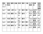
- FIG. 6 is a table showing an example of the data structure of the imaging environment data set.
- the data structure of FIG. 6 has been registered in the imaging environment data set storage database.
- the imaging environment data set detected in step S03 is the imaging environment data set when the subject 400 is imaged in FIG. 5 described above, a similar one is “Set 4” “Horizontal direction of the camera at the time of imaging”
- the subject type is plant
- the distance to the subject is 8 meters
- the illuminance is 240 lux
- the location is outdoors
- the weather is sunny
- the camera type is CameraZ
- the resolution is 5 million pixels It can be determined by collation that it is a set.
- the extraction module 213 of the computer 200 extracts the imaging environment data set “Set4” similar to the detected imaging environment data set (step S05).
- the image analysis module 214 of the computer 200 performs image analysis using the initial value “ParamD” of the image analysis parameter associated with the imaging environment data set “Set4” (step S06).
- “ParamD” the angle from the horizontal direction of the camera at the time of imaging is 10 degrees, the type of subject is human, and the distance to the subject is 3”.
- the image analysis here is appropriate for each purpose, such as face recognition for individual determination, discrimination of pest damage status of crops, inventory check in warehouse, affected area image recognition for medical diagnosis, etc.
- the image analysis parameters are also appropriate according to the above-described purpose, for example, the range for performing the filter process, the intensity of the filter process, the threshold for binarization, the order of the image process, and the like.
- an image analysis system that analyzes an image captured by a camera, an image that improves detection and identification accuracy by image analysis by using parameters that match the environment in which the image was captured.
- An analysis system, an image analysis method, and a program can be provided.
- FIG. 2 is a diagram illustrating the functional blocks of the camera 100 and the computer 200 and the relationship between the functions.
- the camera 100 includes an imaging unit 10, a control unit 110, and a communication unit 120.
- the computer 200 includes a control unit 210, a communication unit 220, a storage unit 230, and an input / output unit 240.
- the control unit 210 implements the detection module 211 in cooperation with the communication unit 220.
- the control unit 210 implements a collation module 212, an extraction module 213, and an image analysis module 214 in cooperation with the storage unit 230.
- the storage unit 230 implements the storage module 231 in cooperation with the control unit 210.
- the communication network 300 may be a public communication network such as the Internet or a dedicated communication network, and enables communication between the camera 100 and the computer 200.
- the camera 100 is an imaging device that includes an imaging device such as an imaging element and a lens that can perform data communication with the computer 200, can measure the distance to the subject, or can simultaneously image the subject from a plurality of different directions.
- a WEB camera is illustrated as an example, but an imaging apparatus having necessary functions such as a digital camera, a digital video, a camera mounted on an unmanned aircraft, a wearable device camera, a security camera, an in-vehicle camera, and a 360-degree camera It may be.
- the camera 100 includes, as the imaging unit 10, an imaging device such as a lens, an imaging device, various buttons, and a flash, and captures images as captured images such as moving images and still images.
- An image obtained by imaging is a precise image having an amount of information necessary for image analysis, and the number of pixels and the image quality can be designated.
- the control unit 110 includes a CPU (Central Processing Unit), a RAM (Random Access Memory), a ROM (Read Only Memory), and the like.
- a CPU Central Processing Unit
- RAM Random Access Memory
- ROM Read Only Memory
- a device for enabling communication with other devices for example, a WiFi (Wireless Fidelity) compatible device compliant with IEEE 802.11 or an IMT-2000 standard such as a third generation or fourth generation mobile communication system. Compliant wireless device etc. It may be a wired LAN connection.
- WiFi Wireless Fidelity
- the computer 200 is a computing device capable of data communication with the camera 100.
- a desktop computer is illustrated as an example, but in addition to a mobile phone, a portable information terminal, a tablet terminal, a personal computer, electrical appliances such as a netbook terminal, a slate terminal, an electronic book terminal, and a portable music player Or a wearable terminal such as a smart glass or a head-mounted display.
- the control unit 210 includes a CPU, RAM, ROM, and the like.
- the control unit 210 implements the detection module 211 in cooperation with the communication unit 220.
- the control unit 210 implements a collation module 212, an extraction module 213, and an image analysis module 214 in cooperation with the storage unit 230.
- a device for enabling communication with other devices as the communication unit 220 for example, a WiFi compatible device compliant with IEEE802.11 or a wireless device compliant with the IMT-2000 standard such as a third generation or fourth generation mobile communication system Etc. It may be a wired LAN connection.
- the storage unit 230 includes a data storage unit such as a hard disk or a semiconductor memory, and data necessary for processing of captured images, imaging environment detection results, imaging environment comparison results, extracted imaging environment data sets, image analysis results, and the like Remember.
- the storage unit 230 implements the storage module 231 in cooperation with the control unit 210.
- the storage unit 230 may include an imaging environment data set storage database.
- the input / output unit 240 has functions necessary for using the image analysis system.
- a liquid crystal display that realizes a touch panel function, a keyboard, a mouse, a pen tablet, a hardware button on the apparatus, a microphone for performing voice recognition, and the like can be provided.
- forms such as a liquid crystal display, a PC display, a projection on a projector, and an audio output can be considered.
- the function of the present invention is not particularly limited by the input / output method.
- FIG. 3 is a flowchart when the computer 200 performs image analysis processing on an image captured by the camera 100. Processing executed by each module described above will be described in accordance with this processing.
- the storage module 231 of the computer 200 stores a plurality of imaging environment data sets in the storage unit 230 (step S301).
- the storage unit 230 may be provided with an imaging environment data set storage database and stored in the database.
- the imaging environment data set refers to environment data at the time of imaging, such as the angle from the horizontal direction of the camera at the time of imaging, the type of subject, the distance to the subject, illuminance, location, weather, camera type, resolution, etc. It is a set.
- an initial value of an image analysis parameter with good subject detection and identification accuracy is associated with each of a plurality of imaging environment data sets and stored in the imaging environment data set storage database in advance. Note that this processing may be skipped when a plurality of imaging environment data sets are already stored.
- the imaging unit 10 of the camera 100 captures an image such as a moving image or a still image of the subject that is the target (step S302).
- the camera 100 images humans, animals, landscapes, articles, agricultural products, trees, and the like as subjects.
- the imaging instruction may be issued from the computer 200.
- the computer 200 acquires an image captured by the camera 100 via the communication unit 220 (step S303).
- the detection module 211 of the computer 200 detects environment data at the time of imaging necessary as information of the imaging environment data set (step S304).
- the environment data at the time of imaging includes, for example, the angle from the horizontal direction of the camera at the time of imaging, the type of the subject, the distance to the subject, the illuminance, the location, the weather, the type of the camera, the resolution, and the like. These data may be directly acquired as data from the camera 100, or may be detected by image analysis of the image acquired in step S303 by the computer 200.
- FIG. 5 is a diagram illustrating an example when the subject 400 is imaged by the camera 100.
- an image “Data A” captured at 12:15:05 on July 7, 2016 by the detection module 211 of the computer 200 connected to the camera 100 via the communication network 300 is “the horizontal direction of the camera at the time of imaging”.
- the angle is 25 degrees
- the subject type is plant
- the distance to the subject is 7 meters
- the illuminance is 250 lux
- the location is outdoors
- the weather is sunny
- the camera type is CameraZ
- the resolution is 5 million pixels. Indicates that it has been detected.
- the angle from the horizontal direction of the camera at the time of imaging (imaging angle) is acquired from the camera 100 or calculated by the computer 200 by a method described later.
- the type of subject is acquired from the camera 100 or detected by image analysis with the computer 200.
- the distance to the subject is acquired from the camera 100 or calculated by the computer 200 by a method described later.
- the illuminance is acquired from the camera 100.
- the location is acquired from the camera 100 or detected by image analysis with the computer 200.
- the weather is detected by image analysis with the computer 200 when the location is outdoors, or weather information of the location of the camera 100 at the time of imaging is acquired from the outside via the communication unit 220.
- the camera type is acquired from the camera 100 or registered in advance in the computer 200.
- the resolution is acquired from the camera 100, the number of pixels of the camera 100 is registered in the computer 200 in advance, or the actual number of pixels of the captured image is calculated.
- the collation module 212 of the computer 200 collates the imaging environment data set of the captured image detected in step S304 with the imaging environment data set stored in the storage unit 230 (step S305).
- FIG. 6 is a table showing an example of the data structure of the imaging environment data set.
- the imaging environment data set detected in step S304 is the imaging environment data set when the subject 400 is imaged in FIG. 5 described above, a similar one is “Set 4” “horizontal direction of the camera at the time of imaging”.
- the extraction module 213 of the computer 200 extracts the imaging environment data set “Set4” similar to the detected imaging environment data set (step S306).
- the image analysis module 214 of the computer 200 performs image analysis using the initial value “ParamD” of the image analysis parameter associated with the imaging environment data set “Set4” (step S307).
- “ParamD” the angle from the horizontal direction of the camera at the time of imaging is 10 degrees, the type of subject is human, and the distance to the subject is 3”.
- the image analysis here is appropriate for each purpose, such as face recognition for individual determination, discrimination of pest damage status of crops, inventory check in warehouse, affected area image recognition for medical diagnosis, etc.
- the image analysis parameters are also appropriate according to the above-described purpose, for example, the range for performing the filter process, the intensity of the filter process, the threshold for binarization, the order of the image process, and the like.
- an image analysis system that analyzes an image captured by a camera, an image that improves detection and identification accuracy by image analysis by using parameters that match the environment in which the image was captured.
- An analysis system, an image analysis method, and a program can be provided.
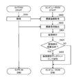
- FIG. 4 is a flowchart when the environment data set used for the image analysis processing is newly stored. Processing executed by each module described above will be described together with this processing. Since the processing from step S401 to step S407 in FIG. 4 corresponds to the processing from step S301 to step S307 in FIG. 3, only step S408 and subsequent steps will be described.
- the storage module 231 confirms whether or not the image analysis result using “ParamD” is satisfactory after the image analysis in step S407 (step S408).
- the storage module 231 associates the imaging environment detected in step S404 with “ParamD” and stores it as a new imaging environment data set (step S409).
- FIG. 7 is a table showing an example of the data structure of the imaging environment data set when the environment data set used for the image analysis process is newly stored.
- “Set 5” is newly set as “An angle from the horizontal direction of the camera at the time of imaging is 25 degrees, the subject type is a plant, the distance to the subject is 7 meters, the illuminance is 250 lux, and the place is outdoor “ParamD” associated with the environmental data set “weather is fine, camera type is CameraZ, and resolution is 5 million pixels” is additionally stored.
- the imaging environment data set of “Set5” can be used from the next imaging.
- step S407 If the image analysis result in step S407 is not good, the storage module 231 does nothing and ends the process.
- step S408 whether or not the image analysis result is good is determined by individual image analysis such as face recognition for individual determination, determination of pest damage status of crops, inventory check in a warehouse, affected part image recognition for medical diagnosis, and the like. Depending on the purpose, it may be determined automatically using a threshold or the like, or may be determined by a human.
- an image analysis system for analyzing an image captured by a camera, by newly registering an imaging environment data set obtained with a good image analysis result, detection by image analysis and Identification accuracy can be improved.
- FIG. 8 is a flowchart for storing an imaging environment data set based on actual imaging. Processing executed by each module described above will be described together with this processing.
- the imaging unit 10 of the camera 100 captures an image such as a moving image or a still image of a subject that is an object (step S801).
- the camera 100 images humans, animals, landscapes, articles, agricultural products, trees, and the like as subjects.
- the computer 200 acquires an image captured by the camera 100 via the communication unit 220 (step S802).
- the detection module 211 of the computer 200 detects necessary environment data at the time of imaging (step S803).
- the environment data at the time of imaging includes, for example, the angle from the horizontal direction of the camera at the time of imaging, the type of the subject, the distance to the subject, the illuminance, the location, the weather, the type of the camera, the resolution, and the like. These data may be directly acquired as data from the camera 100, or may be detected by image analysis of the image acquired in step S802 by the computer 200.
- the image analysis module 214 of the computer 200 performs image analysis (step S804).
- the image processing parameter may be tuned.
- a time limit may be set according to the system.
- the finally used parameters are stored in the storage unit 230 as “ParamX”.
- the image analysis here is appropriate for each purpose, such as face recognition for individual determination, discrimination of pest damage status of crops, inventory check in warehouse, affected area image recognition for medical diagnosis, etc.
- the image analysis parameters are also appropriate according to the above-described purpose, for example, the range for performing the filter process, the intensity of the filter process, the threshold for binarization, the order of the image process, and the like.
- the storage module 231 confirms whether the image analysis result using “ParamX” is satisfactory after the image analysis in step S804 (step S805).
- the storage module 231 associates the imaging environment detected in step S803 with “ParamX” and stores it as a new imaging environment data set (step S806).
- step S804 If the image analysis result in step S804 is not good, the storage module 231 does nothing and ends the process.
- step S804 whether or not the image analysis result is good is determined based on individual image analysis such as face recognition for individual determination, determination of pest damage status of crops, inventory check in a warehouse, and affected part image recognition for medical diagnosis. Depending on the purpose, it may be determined automatically using a threshold or the like, or may be determined by a human.
- a human being inputs an imaging environment data set by newly registering an imaging environment data set based on the captured image. Compared to the case, it is possible to save time and effort.
- the camera 100 is an imaging device that can measure a distance to a subject or can simultaneously image a subject from a plurality of different directions.
- the method of measuring the distance to the subject in addition to obtaining from the sensor of the camera 100 or the like, if the subject can be imaged simultaneously from a plurality of different directions, the difference between the images captured by each of the plurality of cameras is determined. It is also possible to measure the distance by learning the length and the actual distance. Also, it is possible to calculate the imaging angle using the measured distance. Since a method for measuring distances from a plurality of cameras is known as an existing technology, here, a method for acquiring an imaging angle will be described based on FIG.
- FIG. 9 is a diagram for schematically explaining a method for acquiring the imaging angle of the camera 100.
- the camera 100 is in a state where the subject 400, the wall 910, and the floor 920 are imaged.
- the camera 100 or the computer 200 analyzes the captured image and acquires the imaging angle, the area having the same pattern (pattern) area existing in the captured image is recognized as a plane such as a floor or the ground.
- the image capturing angle of itself is acquired from the inclination of.
- the floor 920 corresponds to a plane.
- the method for obtaining the imaging angle of the camera 100 may be performed by either the camera 100 or the computer 200, but for the sake of simplicity, it will be described as being performed by the computer 200 below.
- the computer 200 extracts two predetermined positions 930 and 931 from the imaging position to the floor 920 as samples.
- a triangle 933 is formed connecting the predetermined positions 930 and 931 and the center position 932 of the imaging point.
- the triangle 933 is formed by three sides of a side 940, a side 941, and a side 942.
- the computer 200 forms a perpendicular 950 from the center position 932 to the floor 920 and forms an intersection 934 of the side 942 and the perpendicular 950.
- the computer 200 learns the shift length and actual distance of images captured by a plurality of cameras, and calculates the lengths of the sides 940 and 941 and the perpendicular 950 by estimating the distance.
- the computer 200 calculates the length of the line segment 960 connecting the predetermined position 930 and the intersection point 934 and the line segment 961 connecting the predetermined position 931 and the intersection point 934 on the side 942.
- the computer 200 calculates an angle 970 by using a trigonometric function, and acquires the calculated angle 970 as its own three-dimensional imaging angle.
- the distance to the subject is calculated by using the function of simultaneously imaging the subject from a plurality of different directions.
- the angle from the horizontal direction at the time of imaging can be calculated.
- the means and functions described above are realized by a computer (including a CPU, an information processing apparatus, and various terminals) reading and executing a predetermined program.
- the program may be, for example, in a form (SaaS: Software as a Service) provided from a computer via a network, or a flexible disk, CD (CD-ROM, etc.), DVD (DVD-ROM, DVD). -RAM, etc.) and a computer-readable recording medium such as a compact memory.
- the computer reads the program from the recording medium, transfers it to the internal storage device or the external storage device, stores it, and executes it.
- the program may be recorded in advance in a storage device (recording medium) such as a magnetic disk, an optical disk, or a magneto-optical disk, and provided from the storage device to a computer via a communication line.
Landscapes
- Engineering & Computer Science (AREA)
- Theoretical Computer Science (AREA)
- General Physics & Mathematics (AREA)
- Physics & Mathematics (AREA)
- Multimedia (AREA)
- Computer Vision & Pattern Recognition (AREA)
- Signal Processing (AREA)
- Evolutionary Computation (AREA)
- Data Mining & Analysis (AREA)
- Artificial Intelligence (AREA)
- Databases & Information Systems (AREA)
- Bioinformatics & Computational Biology (AREA)
- Medical Informatics (AREA)
- Computing Systems (AREA)
- General Health & Medical Sciences (AREA)
- Life Sciences & Earth Sciences (AREA)
- Bioinformatics & Cheminformatics (AREA)
- Health & Medical Sciences (AREA)
- Evolutionary Biology (AREA)
- General Engineering & Computer Science (AREA)
- Software Systems (AREA)
- Studio Devices (AREA)
- Image Processing (AREA)
- Image Analysis (AREA)
- Closed-Circuit Television Systems (AREA)
Abstract
【課題】 カメラで撮像した画像を解析する画像解析システムにおいて、画像解析による検出および識別精度を向上させる。 【解決手段】 カメラの設定データおよび被写体に関するデータからなる撮像環境データセットを複数記憶しておき、撮像環境をカメラから検出する検出モジュール211と、撮像環境を照合する照合モジュール212と、検出した撮像環境と類似する撮像環境データセットを抽出する抽出モジュール213とを備え、抽出された撮像環境データセットを適用して画像解析を行う。
Description
本発明は、カメラで撮像した画像を解析する画像解析システムにおいて、撮像を行った環境に合わせたパラメータを使用することで、画像解析による検出および識別精度を向上させる画像解析システム、画像解析方法、およびプログラムに関する。
画像撮影装置には、過去に撮影された記録画像と同じ内容の撮影設定情報を使用して今回の画像撮影をできるようにするものがある(特許文献1)。
しかしながら、特許文献1の装置では、今回の撮影前に記録画像と同じ内容の撮影設定情報を適用する必要があり、既に撮像された画像に対して、適切な画像処理を行うことはできない。近年では、無人航空機に搭載したカメラ、ウェアラブルデバイスのカメラ、防犯カメラ等で撮像した、様々なものが映っている大量の画像を画像解析するニーズが生じており、そのような場合には、撮像前の設定が必要な特許文献1の手法は適さない。また、画像解析を行う際には、画像解析の目的にあわせて被写体の検出や識別を向上させるためのパラメータの調整が必要であるが、調整のための時間や手間の削減が望まれる。
本発明では、これらの課題に鑑み、カメラで撮像した画像を解析する画像解析システムにおいて、撮像を行った環境に合わせたパラメータを使用することで、画像解析による検出および識別精度を向上させる画像解析システム、画像解析方法、およびプログラムを提供することを目的とする。
本発明では、以下のような解決手段を提供する。
第1の特徴に係る発明は、
撮像するカメラの設定データおよび被写体に関するデータからなる撮像環境データセットを複数記憶する記憶手段と、
撮像した画像の撮像環境を前記カメラから検出する検出手段と、
前記検出した撮像環境を、前記記憶手段と照合する照合手段と、
前記照合の結果、前記記憶した複数の撮像環境データセットの中から、前記検出した撮像環境と類似する撮像環境データセットを抽出する抽出手段と、
前記撮像した画像の画像解析を行う際に、前記抽出された撮像環境データセットを適用して画像解析を行う画像解析手段と、
を備えることを特徴とする画像解析システムを提供する。
撮像するカメラの設定データおよび被写体に関するデータからなる撮像環境データセットを複数記憶する記憶手段と、
撮像した画像の撮像環境を前記カメラから検出する検出手段と、
前記検出した撮像環境を、前記記憶手段と照合する照合手段と、
前記照合の結果、前記記憶した複数の撮像環境データセットの中から、前記検出した撮像環境と類似する撮像環境データセットを抽出する抽出手段と、
前記撮像した画像の画像解析を行う際に、前記抽出された撮像環境データセットを適用して画像解析を行う画像解析手段と、
を備えることを特徴とする画像解析システムを提供する。
第1の特徴に係る発明によれば、画像解析システムにおいて、撮像するカメラの設定データおよび被写体に関するデータからなる撮像環境データセットを複数記憶する記憶手段と、撮像した画像の撮像環境を前記カメラから検出する検出手段と、前記検出した撮像環境を、前記記憶手段と照合する照合手段と、前記照合の結果、前記記憶した複数の撮像環境データセットの中から、前記検出した撮像環境と類似する撮像環境データセットを抽出する抽出手段と、前記撮像した画像の画像解析を行う際に、前記抽出された撮像環境データセットを適用して画像解析を行う画像解析手段と、を備える。
第1の特徴に係る発明は、画像解析システムのカテゴリであるが、画像解析方法、およびプログラムであっても同様の作用、効果を奏する。
第2の特徴に係る発明は、第1の特徴に係る発明である画像解析システムであって、
前記記憶手段は、前記画像解析手段で適用された撮像環境データセットを、新たな撮像環境データセットとして記憶することを特徴とする画像解析システムを提供する。
前記記憶手段は、前記画像解析手段で適用された撮像環境データセットを、新たな撮像環境データセットとして記憶することを特徴とする画像解析システムを提供する。
第2の特徴に係る発明によれば、第1の特徴に係る発明である画像解析システムにおいて、前記記憶手段は、前記画像解析手段で適用された撮像環境データセットを、新たな撮像環境データセットとして記憶する。
第3の特徴に係る発明は、第1の特徴または第2の特徴に係る発明である画像解析システムであって、
前記撮像環境データセットは、360度撮像によるデータであることを特徴とする画像解析システムを提供する。
前記撮像環境データセットは、360度撮像によるデータであることを特徴とする画像解析システムを提供する。
第3の特徴に係る発明によれば、第1の特徴または第2の特徴に係る発明である画像解析システムにおいて、前記撮像環境データセットは、360度撮像によるデータである。
第4の特徴に係る発明は、第1の特徴から第3の特徴のいずれかに係る発明である画像解析システムであって、
前記撮像環境データセットには、前記カメラの撮像角度と、前記被写体までの距離と、を含むことを特徴とする画像解析システムを提供する。
前記撮像環境データセットには、前記カメラの撮像角度と、前記被写体までの距離と、を含むことを特徴とする画像解析システムを提供する。
第4の特徴に係る発明によれば、第1の特徴から第3の特徴のいずれかに係る発明である画像解析システムにおいて、前記撮像環境データセットには、前記カメラの撮像角度と、前記被写体までの距離と、を含む。
第5の特徴に係る発明は、
撮像するカメラの設定データと被写体に関するデータとからなる撮像環境データセットを複数記憶するステップと、
撮像した画像の撮像環境を前記カメラから検出するステップと、
前記検出した撮像環境を、前記記憶した複数の撮像環境データセットと照合するステップと、
前記照合の結果、前記記憶した複数の撮像環境データセットの中から、前記検出した撮像環境と類似する撮像環境データセットを抽出するステップと、
前記撮像した画像の画像解析を行う際に、前記抽出された撮像環境データセットを適用して画像解析を行うステップと、
を備えることを特徴とする画像解析方法を提供する。
撮像するカメラの設定データと被写体に関するデータとからなる撮像環境データセットを複数記憶するステップと、
撮像した画像の撮像環境を前記カメラから検出するステップと、
前記検出した撮像環境を、前記記憶した複数の撮像環境データセットと照合するステップと、
前記照合の結果、前記記憶した複数の撮像環境データセットの中から、前記検出した撮像環境と類似する撮像環境データセットを抽出するステップと、
前記撮像した画像の画像解析を行う際に、前記抽出された撮像環境データセットを適用して画像解析を行うステップと、
を備えることを特徴とする画像解析方法を提供する。
第6の特徴に係る発明は、コンピュータシステムに、
撮像するカメラの設定データと被写体に関するデータとからなる撮像環境データセットを複数記憶するステップ、
撮像した画像の撮像環境を前記カメラから検出するステップ、
前記検出した撮像環境を、前記記憶した複数の撮像環境データセットと照合するステップ、
前記照合の結果、前記記憶した複数の撮像環境データセットの中から、前記検出した撮像環境と類似する撮像環境データセットを抽出するステップ、
前記撮像した画像の画像解析を行う際に、前記抽出された撮像環境データセットを適用して画像解析を行うステップ、
を実行させるためのプログラムを提供する。
撮像するカメラの設定データと被写体に関するデータとからなる撮像環境データセットを複数記憶するステップ、
撮像した画像の撮像環境を前記カメラから検出するステップ、
前記検出した撮像環境を、前記記憶した複数の撮像環境データセットと照合するステップ、
前記照合の結果、前記記憶した複数の撮像環境データセットの中から、前記検出した撮像環境と類似する撮像環境データセットを抽出するステップ、
前記撮像した画像の画像解析を行う際に、前記抽出された撮像環境データセットを適用して画像解析を行うステップ、
を実行させるためのプログラムを提供する。
本発明によれば、カメラで撮像した画像を解析する画像解析システムにおいて、撮像を行った環境に合わせたパラメータを使用することで、画像解析による検出および識別精度を向上させる画像解析システム、画像解析方法、およびプログラムを提供することが可能となる。
以下、本発明を実施するための最良の形態について図を参照しながら説明する。なお、これはあくまでも一例であって、本発明の技術的範囲はこれに限られるものではない。
[画像解析システムの概要]
図1は、本発明の好適な実施形態の概要図である。この図1に基づいて、本発明の概要を説明する。画像解析システムは、カメラ100、コンピュータ200、通信網300から構成される。
図1は、本発明の好適な実施形態の概要図である。この図1に基づいて、本発明の概要を説明する。画像解析システムは、カメラ100、コンピュータ200、通信網300から構成される。
なお、図1において、カメラ100の数は1つに限らず複数であってもよい。また、コンピュータ200は、実在する装置に限らず、仮想的な装置であってもよい。
カメラ100は、図2に示すように、撮像部10、制御部110、通信部120から構成される。また、コンピュータ200は、同じく図2に示すように、制御部210、通信部220、記憶部230、入出力部240、から構成される。制御部210は通信部220と協働して検出モジュール211を実現する。また、制御部210は記憶部230と協働して照合モジュール212、抽出モジュール213、画像解析モジュール214を実現する。また、記憶部230は、制御部210と協働して記憶モジュール231を実現する。通信網300は、インターネット等の公衆通信網でも専用通信網でも良く、カメラ100とコンピュータ200間の通信を可能とする。
カメラ100は、コンピュータ200とデータ通信可能な、撮像素子やレンズ等の撮像デバイスを備え、被写体までの距離を測定可能な、または、被写体を複数の異なる方向から同時に撮像可能な撮像装置である。ここでは、例としてWEBカメラを図示しているが、デジタルカメラ、デジタルビデオ、無人航空機に搭載したカメラ、ウェアラブルデバイスのカメラ、防犯カメラ、車載カメラ、360度カメラ等の必要な機能を備える撮像装置であってよい。
コンピュータ200は、カメラ100とデータ通信可能な計算装置である。ここでは、例としてデスクトップ型のコンピュータを図示しているが、携帯電話、携帯情報端末、タブレット端末、パーソナルコンピュータに加え、ネットブック端末、スレート端末、電子書籍端末、携帯型音楽プレーヤ等の電化製品や、スマートグラス、ヘッドマウントディスプレイ等のウェアラブル端末等であってよい。
図1の画像解析システムにおいて、コンピュータ200は、撮像環境データセット記憶データベースを備える。ここで、撮像環境データセットとは、撮像時のカメラの水平方向からの角度、被写体の種類、被写体までの距離、照度、場所、天候、カメラの種類、解像度、等の撮像時の環境データをセットとしたものである。コンピュータ200の記憶モジュール231は、あらかじめ複数の撮像環境データセットそれぞれに対して、被写体の検出および識別精度が良い画像解析パラメータの初期値を紐付けして、撮像環境データセット記憶データベースに記憶しておくものとする。
カメラ100の撮像部10は、対象物である被写体の動画又は静止画等の画像を撮像する(ステップS01)。カメラ100は、被写体として、人間、動物、風景、物品、農作物、樹木等を撮像する。
コンピュータ200は、通信部220を介して、カメラ100が撮像した画像を取得する(ステップS02)。
コンピュータ200の検出モジュール211は、撮像環境データセットの情報として必要な撮像時の環境データを検出する(ステップS03)。撮像時の環境データとは、例えば、撮像時のカメラの水平方向からの角度、被写体の種類、被写体までの距離、照度、場所、天候、カメラの種類、解像度、等である。これらのデータは、カメラ100からデータとして直接取得しても良いし、ステップS02で取得した画像をコンピュータ200で画像解析することにより検出しても良い。
図5は、カメラ100で被写体400を撮像した場合の一例を示す図である。ここでは、カメラ100と通信網300で接続されたコンピュータ200の検出モジュール211が、2016年7月7日の12:15:05に撮像したData Aという画像が、「撮像時のカメラの水平方向からの角度が25度、被写体の種類が植物、被写体までの距離が7メートル、照度が250ルクス、場所が屋外、天候が晴れ、カメラの種類がCameraZ、解像度が500万画素」であることを検出したことを示している。撮像時のカメラの水平方向からの角度(撮像角度)は、カメラ100から取得するか、コンピュータ200で後述する方法により算出するものとする。被写体の種類は、カメラ100から取得するか、コンピュータ200での画像解析により検出するものとする。被写体までの距離は、カメラ100から取得するか、コンピュータ200で後述する方法により算出するものとする。照度は、カメラ100から取得するものとする。場所は、カメラ100から取得するか、コンピュータ200での画像解析により検出するものとする。天候は、場所が屋外である場合に、コンピュータ200での画像解析により検出するか、撮像時のカメラ100の場所の天気情報を、通信部220を介して外部より取得するものとする。カメラの種類は、カメラ100から取得するか、事前にコンピュータ200に登録しておくものとする。解像度は、カメラ100から取得するか、事前にコンピュータ200にカメラ100の画素数を登録しておくか、撮像画像の実際の画素数を算出するものとする。
コンピュータ200の照合モジュール212は、ステップS03で検出した撮像画像の撮像環境データセットと、撮像環境データセット記憶データベースに登録済の撮像環境データセットとを照合する(ステップS04)。
図6は、撮像環境データセットのデータ構造の一例を示す表である。ここでは、撮像環境データセット記憶データベースに、図6のデータ構造が登録済であるとする。ステップS03で検出した撮像環境データセットが、前述の図5で被写体400を撮像した場合の撮像環境データセットである場合、これと類似したものは、「Set4」の「撮像時のカメラの水平方向からの角度が30度、被写体の種類が植物、被写体までの距離が8メートル、照度が240ルクス、場所が屋外、天候が晴れ、カメラの種類がCameraZ、解像度が500万画素」である環境データセットであることが照合により判定できる。
コンピュータ200の抽出モジュール213は、検出した撮像環境データセットと類似した「Set4」の撮像環境データセットを抽出する(ステップS05)。
コンピュータ200の画像解析モジュール214は、「Set4」の撮像環境データセットに紐付けられた画像解析パラメータの初期値「ParamD」を利用して画像解析を行う(ステップS06)。ここで、「ParamD」を使用して画像解析を行うことで、例えば、「Set1」の「撮像時のカメラの水平方向からの角度が10度、被写体の種類が人間、被写体までの距離が3メートル、照度が100ルクス、場所が屋外、天候が曇り、カメラの種類がCameraX、解像度が250万画素」の環境データセットに適した画像解析パラメータの初期値「ParamA」を使用して画像解析を行う場合より、短時間で識別精度の良い結果を得ることが可能である。
ここでの画像解析は、例えば、個人判定用の顔認識、農作物の害虫被害状況の判別、倉庫内の在庫確認、医療診断用の患部画像認識、等、個々の目的に応じた適切なものであるとする。また、画像解析パラメータも、前述の目的に応じて、例えば、フィルタ処理を行う範囲、フィルタ処理の強度、二値化の閾値、画像処理の順番、等、適切なものであるとする。
以上のように、本発明によれば、カメラで撮像した画像を解析する画像解析システムにおいて、撮像を行った環境に合わせたパラメータを使用することで、画像解析による検出および識別精度を向上させる画像解析システム、画像解析方法、およびプログラムを提供することが可能となる。
[各機能の説明]
図2は、カメラ100とコンピュータ200の機能ブロックと各機能の関係を示す図である。カメラ100は、撮像部10、制御部110、通信部120から構成される。また、コンピュータ200は、制御部210、通信部220、記憶部230、入出力部240、から構成される。制御部210は通信部220と協働して検出モジュール211を実現する。また、制御部210は記憶部230と協働して照合モジュール212、抽出モジュール213、画像解析モジュール214を実現する。また、記憶部230は、制御部210と協働して記憶モジュール231を実現する。通信網300は、インターネット等の公衆通信網でも専用通信網でも良く、カメラ100とコンピュータ200間の通信を可能とする。
図2は、カメラ100とコンピュータ200の機能ブロックと各機能の関係を示す図である。カメラ100は、撮像部10、制御部110、通信部120から構成される。また、コンピュータ200は、制御部210、通信部220、記憶部230、入出力部240、から構成される。制御部210は通信部220と協働して検出モジュール211を実現する。また、制御部210は記憶部230と協働して照合モジュール212、抽出モジュール213、画像解析モジュール214を実現する。また、記憶部230は、制御部210と協働して記憶モジュール231を実現する。通信網300は、インターネット等の公衆通信網でも専用通信網でも良く、カメラ100とコンピュータ200間の通信を可能とする。
カメラ100は、コンピュータ200とデータ通信可能な、撮像素子やレンズ等の撮像デバイスを備え、被写体までの距離を測定可能な、または、被写体を複数の異なる方向から同時に撮像可能な撮像装置である。ここでは、例としてWEBカメラを図示しているが、デジタルカメラ、デジタルビデオ、無人航空機に搭載したカメラ、ウェアラブルデバイスのカメラ、防犯カメラ、車載カメラ、360度カメラ等の必要な機能を備える撮像装置であってよい。
カメラ100は、撮像部10として、レンズ、撮像素子、各種ボタン、フラッシュ等の撮像デバイス等を備え、動画や静止画等の撮像画像として撮像する。また、撮像して得られる画像は、画像解析に必要なだけの情報量を持った精密な画像であるものとし、画素数や画質を指定可能であるものとする。
制御部110として、CPU(Central Processing Unit)、RAM(Random Access Memory)、ROM(Read Only Memory)等を備える。
通信部120として、他の機器と通信可能にするためのデバイス、例えば、IEEE802.11に準拠したWiFi(Wireless Fidelity)対応デバイス又は第3世代、第4世代移動通信システム等のIMT-2000規格に準拠した無線デバイス等を備える。有線によるLAN接続であってもよい。
コンピュータ200は、カメラ100とデータ通信可能な計算装置である。ここでは、例としてデスクトップ型のコンピュータを図示しているが、携帯電話、携帯情報端末、タブレット端末、パーソナルコンピュータに加え、ネットブック端末、スレート端末、電子書籍端末、携帯型音楽プレーヤ等の電化製品や、スマートグラス、ヘッドマウントディスプレイ等のウェアラブル端末等であってよい。
制御部210として、CPU、RAM、ROM等を備える。制御部210は通信部220と協働して検出モジュール211を実現する。また、制御部210は記憶部230と協働して照合モジュール212、抽出モジュール213、画像解析モジュール214を実現する。
通信部220として、他の機器と通信可能にするためのデバイス、例えば、IEEE802.11に準拠したWiFi対応デバイス又は第3世代、第4世代移動通信システム等のIMT-2000規格に準拠した無線デバイス等を備える。有線によるLAN接続であってもよい。
記憶部230として、ハードディスクや半導体メモリによる、データのストレージ部を備え、撮像画像や、撮像環境検出結果、撮像環境照合結果、抽出した撮像環境データセット、画像解析結果等の処理に必要なデータ等を記憶する。また、記憶部230は、制御部210と協働して記憶モジュール231を実現する。記憶部230に、撮像環境データセット記憶データベースを備えても良い。
入出力部240は、画像解析システムを利用するために必要な機能を備えるものとする。入力を実現するための例として、タッチパネル機能を実現する液晶ディスプレイ、キーボード、マウス、ペンタブレット、装置上のハードウェアボタン、音声認識を行うためのマイク等を備えることが可能である。また、出力を実現するための例として、液晶ディスプレイ、PCのディスプレイ、プロジェクターへの投影等の表示と音声出力等の形態が考えられる。入出力方法により、本発明は特に機能を限定されるものではない。
[画像解析処理]
図3は、カメラ100での撮像画像をコンピュータ200で画像解析処理を行う場合のフローチャート図である。上述した各モジュールが実行する処理について、本処理にあわせて説明する。
図3は、カメラ100での撮像画像をコンピュータ200で画像解析処理を行う場合のフローチャート図である。上述した各モジュールが実行する処理について、本処理にあわせて説明する。
はじめに、コンピュータ200の記憶モジュール231は、記憶部230に撮像環境データセットを複数記憶する(ステップS301)。記憶部230に撮像環境データセット記憶データベースを備え、データベースに記憶することとしてもよい。ここで、撮像環境データセットとは、撮像時のカメラの水平方向からの角度、被写体の種類、被写体までの距離、照度、場所、天候、カメラの種類、解像度、等の撮像時の環境データをセットとしたものである。ここであらかじめ、複数の撮像環境データセットそれぞれに対して、被写体の検出および識別精度が良い画像解析パラメータの初期値を紐付けして、撮像環境データセット記憶データベースに記憶しておくものとする。なお、既に複数の撮像環境データセットが記憶されている場合には、この処理はスキップしてよいものとする。
次に、カメラ100の撮像部10は、対象物である被写体の動画又は静止画等の画像を撮像する(ステップS302)。カメラ100は、被写体として、人間、動物、風景、物品、農作物、樹木等を撮像する。撮像の指示は、コンピュータ200から行っても良い。
コンピュータ200は、通信部220を介して、カメラ100が撮像した画像を取得する(ステップS303)。
コンピュータ200の検出モジュール211は、撮像環境データセットの情報として必要な撮像時の環境データを検出する(ステップS304)。撮像時の環境データとは、例えば、撮像時のカメラの水平方向からの角度、被写体の種類、被写体までの距離、照度、場所、天候、カメラの種類、解像度、等である。これらのデータは、カメラ100からデータとして直接取得しても良いし、ステップS303で取得した画像をコンピュータ200で画像解析することにより検出しても良い。
図5は、カメラ100で被写体400を撮像した場合の一例を示す図である。ここでは、カメラ100と通信網300で接続されたコンピュータ200の検出モジュール211が、2016年7月7日の12:15:05に撮像したData Aという画像が、「撮像時のカメラの水平方向からの角度が25度、被写体の種類が植物、被写体までの距離が7メートル、照度が250ルクス、場所が屋外、天候が晴れ、カメラの種類がCameraZ、解像度が500万画素」であることを検出したことを示している。撮像時のカメラの水平方向からの角度(撮像角度)は、カメラ100から取得するか、コンピュータ200で後述する方法により算出するものとする。被写体の種類は、カメラ100から取得するか、コンピュータ200での画像解析により検出するものとする。被写体までの距離は、カメラ100から取得するか、コンピュータ200で後述する方法により算出するものとする。照度は、カメラ100から取得するものとする。場所は、カメラ100から取得するか、コンピュータ200での画像解析により検出するものとする。天候は、場所が屋外である場合に、コンピュータ200での画像解析により検出するか、撮像時のカメラ100の場所の天気情報を、通信部220を介して外部より取得するものとする。カメラの種類は、カメラ100から取得するか、事前にコンピュータ200に登録しておくものとする。解像度は、カメラ100から取得するか、事前にコンピュータ200にカメラ100の画素数を登録しておくか、撮像画像の実際の画素数を算出するものとする。
コンピュータ200の照合モジュール212は、ステップS304で検出した撮像画像の撮像環境データセットと、記憶部230に記憶済の撮像環境データセットとを照合する(ステップS305)。
図6は、撮像環境データセットのデータ構造の一例を示す表である。ここでは、撮像環境データセット記憶データベースに、図6のデータ構造が登録済であるとする。ステップS304で検出した撮像環境データセットが、前述の図5で被写体400を撮像した場合の撮像環境データセットである場合、これと類似したものは、「Set4」の「撮像時のカメラの水平方向からの角度が30度、被写体の種類が植物、被写体までの距離が8メートル、照度が240ルクス、場所が屋外、天候が晴れ、カメラの種類がCameraZ、解像度が500万画素」である環境データセットであることが照合により判定できる。
コンピュータ200の抽出モジュール213は、検出した撮像環境データセットと類似した「Set4」の撮像環境データセットを抽出する(ステップS306)。
コンピュータ200の画像解析モジュール214は、「Set4」の撮像環境データセットに紐付けられた画像解析パラメータの初期値「ParamD」を利用して画像解析を行う(ステップS307)。ここで、「ParamD」を使用して画像解析を行うことで、例えば、「Set1」の「撮像時のカメラの水平方向からの角度が10度、被写体の種類が人間、被写体までの距離が3メートル、照度が100ルクス、場所が屋外、天候が曇り、カメラの種類がCameraX、解像度が250万画素」の環境データセットに適した画像解析パラメータの初期値「ParamA」を使用して画像解析を行う場合より、短時間で識別精度の良い結果を得ることが可能である。
ここでの画像解析は、例えば、個人判定用の顔認識、農作物の害虫被害状況の判別、倉庫内の在庫確認、医療診断用の患部画像認識、等、個々の目的に応じた適切なものであるとする。また、画像解析パラメータも、前述の目的に応じて、例えば、フィルタ処理を行う範囲、フィルタ処理の強度、二値化の閾値、画像処理の順番、等、適切なものであるとする。
以上のように、本発明によれば、カメラで撮像した画像を解析する画像解析システムにおいて、撮像を行った環境に合わせたパラメータを使用することで、画像解析による検出および識別精度を向上させる画像解析システム、画像解析方法、およびプログラムを提供することが可能となる。
[撮像環境データセット追加記憶処理]
図4は、画像解析処理に使用した環境データセットを新たに記憶させる場合のフローチャート図である。上述した各モジュールが実行する処理について、本処理に併せて説明する。図4のステップS401からステップS407の処理は、図3のステップS301からステップS307の処理に相当するため、ステップS408以降について説明する。
図4は、画像解析処理に使用した環境データセットを新たに記憶させる場合のフローチャート図である。上述した各モジュールが実行する処理について、本処理に併せて説明する。図4のステップS401からステップS407の処理は、図3のステップS301からステップS307の処理に相当するため、ステップS408以降について説明する。
記憶モジュール231は、ステップS407での画像解析後、「ParamD」を使用した画像解析結果が、良好であったかどうかを確認する(ステップS408)。
ステップS407の画像解析結果が良好であった場合には、記憶モジュール231は、ステップS404で検出した撮像環境を「ParamD」と紐付けて、新たな撮像環境データセットとして記憶する(ステップS409)。
図7は、画像解析処理に使用した環境データセットを新たに記憶させた場合の撮像環境データセットのデータ構造の一例を示す表である。図6の状態から、新たに「Set5」として、「撮像時のカメラの水平方向からの角度が25度、被写体の種類が植物、被写体までの距離が7メートル、照度が250ルクス、場所が屋外、天候が晴れ、カメラの種類がCameraZ、解像度が500万画素」の環境データセットと紐付けた「ParamD」を、追加して記憶させている。これにより、次回撮像時から「Set5」の撮像環境データセットも利用可能となる。
ステップS407の画像解析結果が良好でなかった場合には、記憶モジュール231はなにも行わず処理を終了する。
ステップS408において、画像解析結果が良好であったかどうかとは、個人判定用の顔認識、農作物の害虫被害状況の判別、倉庫内の在庫確認、医療診断用の患部画像認識、等、個々の画像解析の目的に応じて閾値等を用いて自動で判断しても良いし、人間が判断してもよい。
以上のように、本発明によれば、カメラで撮像した画像を解析する画像解析システムにおいて、良好な画像解析結果を得た撮像環境データセットを新たに登録することで、より画像解析による検出および識別精度を向上させることが可能となる。
[撮像画像を基にした撮像環境データセット記憶処理]
図8は、実際の撮像を基に撮像環境データセットを記憶させる場合のフローチャート図である。上述した各モジュールが実行する処理について、本処理に併せて説明する。
図8は、実際の撮像を基に撮像環境データセットを記憶させる場合のフローチャート図である。上述した各モジュールが実行する処理について、本処理に併せて説明する。
はじめに、カメラ100の撮像部10は、対象物である被写体の動画又は静止画等の画像を撮像する(ステップS801)。カメラ100は、被写体として、人間、動物、風景、物品、農作物、樹木等を撮像する。
コンピュータ200は、通信部220を介して、カメラ100が撮像した画像を取得する(ステップS802)。
コンピュータ200の検出モジュール211は、必要な撮像時の環境データを検出する(ステップS803)。撮像時の環境データとは、例えば、撮像時のカメラの水平方向からの角度、被写体の種類、被写体までの距離、照度、場所、天候、カメラの種類、解像度、等である。これらのデータは、カメラ100からデータとして直接取得しても良いし、ステップS802で取得した画像をコンピュータ200で画像解析することにより検出しても良い。
コンピュータ200の画像解析モジュール214は、画像解析を行う(ステップS804)。ここでは、画像処理パラメータの適切な初期値が特に指定されていないため、画像処理パラメータのチューニングを行っても良い。チューニングを行う際は、システムに応じて時間等による制限をつけても良い。ここで、最終的に使用したパラメータを「ParamX」として記憶部230に記憶しておく。
ここでの画像解析は、例えば、個人判定用の顔認識、農作物の害虫被害状況の判別、倉庫内の在庫確認、医療診断用の患部画像認識、等、個々の目的に応じた適切なものであるとする。また、画像解析パラメータも、前述の目的に応じて、例えば、フィルタ処理を行う範囲、フィルタ処理の強度、二値化の閾値、画像処理の順番、等、適切なものであるとする。
次に、記憶モジュール231は、ステップS804での画像解析後、「ParamX」を使用した画像解析結果が、良好であったかどうかを確認する(ステップS805)。
ステップS804の画像解析結果が良好であった場合には、記憶モジュール231は、ステップS803で検出した撮像環境を「ParamX」と紐付けて、新たな撮像環境データセットとして記憶する(ステップS806)。
ステップS804の画像解析結果が良好でなかった場合には、記憶モジュール231はなにも行わず処理を終了する。
ステップS804において、画像解析結果が良好であったかどうかとは、個人判定用の顔認識、農作物の害虫被害状況の判別、倉庫内の在庫確認、医療診断用の患部画像認識、等、個々の画像解析の目的に応じて閾値等を用いて自動で判断しても良いし、人間が判断してもよい。
以上のように、本発明によれば、カメラで撮像した画像を解析する画像解析システムにおいて、撮像画像を基にした撮像環境データセットを新たに登録することで、撮像環境データセットを人間が入力する場合に比較して、手間を省くことが可能となる。
[撮像角度取得処理]
本発明でのカメラ100は、被写体までの距離を測定可能、または、被写体を複数の異なる方向から同時に撮像可能な撮像装置である。被写体までの距離を測定する方法については、カメラ100のセンサ等から取得する他に、被写体を複数の異なる方向から同時に撮像可能である場合には、その複数のカメラそれぞれで撮像した画像のズレの長さと、実際の距離を学習させて、距離を測定することも可能である。また、その測定した距離を用いて、撮像角度を算出することも可能である。複数のカメラから距離を測定する方法については、既存技術として知られているため、ここでは、図9に基づいて、撮像角度を取得する方法について説明する。
本発明でのカメラ100は、被写体までの距離を測定可能、または、被写体を複数の異なる方向から同時に撮像可能な撮像装置である。被写体までの距離を測定する方法については、カメラ100のセンサ等から取得する他に、被写体を複数の異なる方向から同時に撮像可能である場合には、その複数のカメラそれぞれで撮像した画像のズレの長さと、実際の距離を学習させて、距離を測定することも可能である。また、その測定した距離を用いて、撮像角度を算出することも可能である。複数のカメラから距離を測定する方法については、既存技術として知られているため、ここでは、図9に基づいて、撮像角度を取得する方法について説明する。
図9は、カメラ100の撮像角度を取得する方法を模式的に説明するための図である。図9において、カメラ100は、被写体400と、壁910と、床920を撮像した状態である。カメラ100またはコンピュータ200が、撮像画像を画像解析し、撮像角度を取得する場合、撮像画像中に存在する同じパターン(模様)面積が、最大の領域を床又は地面等の平面と認識し、平面の傾きから自身の撮像角度を取得する。ここでは、床920が平面に該当する。
カメラ100の撮像角度を取得する方法は、カメラ100またはコンピュータ200のいずれで行っても良いが、以下では簡略化のために、コンピュータ200で行うものとして記載する。コンピュータ200は、撮像位置から床920までの2か所の所定位置930,931をサンプルとして抽出する。この所定位置930,931と、撮像地点の中心位置932とを結んだ三角形933を形成する。三角形933は、辺940、辺941、辺942の3辺により形成される。コンピュータ200は、中心位置932から床920へ垂線950を形成し、辺942と垂線950の交点934を形成する。コンピュータ200は、複数のカメラで撮像した画像のずれの長さと実際の距離を学習させ、距離を推定することにより辺940,941及び垂線950の長さを算出する。コンピュータ200は、辺942において、所定位置930と交点934とを結ぶ線分960と、所定位置931と交点934とを結ぶ線分961との長さを算出する。コンピュータ200は、三角関数により、角度970を算出し、この算出した角度970を自身の3次元の撮像角度として取得する。
以上のように、本発明によれば、カメラに被写体までの距離を測定する機能が無い場合にも、被写体を複数の異なる方向から同時に撮像する機能を利用することにより、被写体までの距離を算出するとともに、撮像時の水平方向からの角度を算出することが可能である。
上述した手段、機能は、コンピュータ(CPU、情報処理装置、各種端末を含む)が、所定のプログラムを読み込んで、実行することによって実現される。プログラムは、例えば、コンピュータからネットワーク経由で提供される(SaaS:ソフトウェア・アズ・ア・サービス)形態であってもよいし、フレキシブルディスク、CD(CD-ROMなど)、DVD(DVD-ROM、DVD-RAMなど)、コンパクトメモリ等のコンピュータ読取可能な記録媒体に記録された形態で提供される。この場合、コンピュータはその記録媒体からプログラムを読み取って内部記憶装置又は外部記憶装置に転送し記憶して実行する。また、そのプログラムを、例えば、磁気ディスク、光ディスク、光磁気ディスク等の記憶装置(記録媒体)に予め記録しておき、その記憶装置から通信回線を介してコンピュータに提供するようにしてもよい。
以上、本発明の実施形態について説明したが、本発明は上述したこれらの実施形態に限るものではない。また、本発明の実施形態に記載された効果は、本発明から生じる最も好適な効果を列挙したに過ぎず、本発明による効果は、本発明の実施形態に記載されたものに限定されるものではない。
100 カメラ、200 コンピュータ、300 通信網、400 被写体
Claims (6)
- 撮像するカメラの設定データおよび被写体に関するデータからなる撮像環境データセットを複数記憶する記憶手段と、
撮像した画像の撮像環境を前記カメラから検出する検出手段と、
前記検出した撮像環境を、前記記憶手段と照合する照合手段と、
前記照合の結果、前記記憶した複数の撮像環境データセットの中から、前記検出した撮像環境と類似する撮像環境データセットを抽出する抽出手段と、
前記撮像した画像の画像解析を行う際に、前記抽出された撮像環境データセットを適用して画像解析を行う画像解析手段と、を備えることを特徴とする画像解析システム。 - 前記記憶手段は、前記画像解析手段で適用された撮像環境データセットを、新たな撮像環境データセットとして記憶することを特徴とする請求項1に記載の画像解析システム。
- 前記撮像環境データセットは、360度撮像によるデータであることを特徴とする請求項1または請求項2に記載の画像解析システム。
- 前記撮像環境データセットには、前記カメラの撮像角度と、前記被写体までの距離と、を含むことを特徴とする請求項1から請求項3のいずれかに記載の画像解析システム。
- 撮像するカメラの設定データと被写体に関するデータとからなる撮像環境データセットを複数記憶するステップと、
撮像した画像の撮像環境を前記カメラから検出するステップと、
前記検出した撮像環境を、前記記憶した複数の撮像環境データセットと照合するステップと、
前記照合の結果、前記記憶した複数の撮像環境データセットの中から、前記検出した撮像環境と類似する撮像環境データセットを抽出するステップと、
前記撮像した画像の画像解析を行う際に、前記抽出された撮像環境データセットを適用して画像解析を行うステップと、を備えることを特徴とする画像解析方法。 - コンピュータシステムに、
撮像するカメラの設定データと被写体に関するデータとからなる撮像環境データセットを複数記憶するステップ、
撮像した画像の撮像環境を前記カメラから検出するステップ、
前記検出した撮像環境を、前記記憶した複数の撮像環境データセットと照合するステップ、
前記照合の結果、前記記憶した複数の撮像環境データセットの中から、前記検出した撮像環境と類似する撮像環境データセットを抽出するステップ、
前記撮像した画像の画像解析を行う際に、前記抽出された撮像環境データセットを適用して画像解析を行うステップ、を実行させるためのプログラム。
Priority Applications (3)
| Application Number | Priority Date | Filing Date | Title |
|---|---|---|---|
| PCT/JP2016/082296 WO2018078861A1 (ja) | 2016-10-31 | 2016-10-31 | 画像解析システム、画像解析方法、およびプログラム |
| JP2017545424A JP6246440B1 (ja) | 2016-10-31 | 2016-10-31 | 画像解析システム、画像解析方法、およびプログラム |
| US15/553,607 US10440331B2 (en) | 2016-10-31 | 2016-10-31 | System, method, and program for image analysis |
Applications Claiming Priority (1)
| Application Number | Priority Date | Filing Date | Title |
|---|---|---|---|
| PCT/JP2016/082296 WO2018078861A1 (ja) | 2016-10-31 | 2016-10-31 | 画像解析システム、画像解析方法、およびプログラム |
Publications (1)
| Publication Number | Publication Date |
|---|---|
| WO2018078861A1 true WO2018078861A1 (ja) | 2018-05-03 |
Family
ID=60659098
Family Applications (1)
| Application Number | Title | Priority Date | Filing Date |
|---|---|---|---|
| PCT/JP2016/082296 Ceased WO2018078861A1 (ja) | 2016-10-31 | 2016-10-31 | 画像解析システム、画像解析方法、およびプログラム |
Country Status (3)
| Country | Link |
|---|---|
| US (1) | US10440331B2 (ja) |
| JP (1) | JP6246440B1 (ja) |
| WO (1) | WO2018078861A1 (ja) |
Families Citing this family (1)
| Publication number | Priority date | Publication date | Assignee | Title |
|---|---|---|---|---|
| JP7677106B2 (ja) * | 2021-10-08 | 2025-05-15 | 三菱電機株式会社 | 画像解析装置および画像解析方法 |
Citations (4)
| Publication number | Priority date | Publication date | Assignee | Title |
|---|---|---|---|---|
| JP2000306095A (ja) * | 1999-04-16 | 2000-11-02 | Fujitsu Ltd | 画像照合・検索システム |
| JP2011192093A (ja) * | 2010-03-15 | 2011-09-29 | Omron Corp | 照合装置、デジタル画像処理システム、照合装置制御プログラム、コンピュータ読み取り可能な記録媒体、および照合装置の制御方法 |
| JP2015023512A (ja) * | 2013-07-22 | 2015-02-02 | オリンパスイメージング株式会社 | 撮影装置、撮影方法及び撮影装置の撮影プログラム |
| JP2016051904A (ja) * | 2014-08-28 | 2016-04-11 | オリンパス株式会社 | 撮影支援装置、撮影支援システム、撮影支援方法及び撮影支援プログラム |
Family Cites Families (1)
| Publication number | Priority date | Publication date | Assignee | Title |
|---|---|---|---|---|
| JP5019228B2 (ja) | 2008-03-17 | 2012-09-05 | Necカシオモバイルコミュニケーションズ株式会社 | 画像撮影装置及びプログラム |
-
2016
- 2016-10-31 JP JP2017545424A patent/JP6246440B1/ja active Active
- 2016-10-31 US US15/553,607 patent/US10440331B2/en active Active
- 2016-10-31 WO PCT/JP2016/082296 patent/WO2018078861A1/ja not_active Ceased
Patent Citations (4)
| Publication number | Priority date | Publication date | Assignee | Title |
|---|---|---|---|---|
| JP2000306095A (ja) * | 1999-04-16 | 2000-11-02 | Fujitsu Ltd | 画像照合・検索システム |
| JP2011192093A (ja) * | 2010-03-15 | 2011-09-29 | Omron Corp | 照合装置、デジタル画像処理システム、照合装置制御プログラム、コンピュータ読み取り可能な記録媒体、および照合装置の制御方法 |
| JP2015023512A (ja) * | 2013-07-22 | 2015-02-02 | オリンパスイメージング株式会社 | 撮影装置、撮影方法及び撮影装置の撮影プログラム |
| JP2016051904A (ja) * | 2014-08-28 | 2016-04-11 | オリンパス株式会社 | 撮影支援装置、撮影支援システム、撮影支援方法及び撮影支援プログラム |
Also Published As
| Publication number | Publication date |
|---|---|
| JP6246440B1 (ja) | 2017-12-13 |
| US20180350091A1 (en) | 2018-12-06 |
| US10440331B2 (en) | 2019-10-08 |
| JPWO2018078861A1 (ja) | 2018-11-01 |
Similar Documents
| Publication | Publication Date | Title |
|---|---|---|
| JP6246441B1 (ja) | 画像解析システム、画像解析方法、およびプログラム | |
| TW201911130A (zh) | 一種翻拍影像識別方法及裝置 | |
| TW202026948A (zh) | 活體檢測方法、裝置以及儲存介質 | |
| EP3093822B1 (en) | Displaying a target object imaged in a moving picture | |
| JP6404527B1 (ja) | カメラ制御システム、カメラ制御方法、およびプログラム | |
| US12335603B2 (en) | Electronic device comprising multi-camera, and photographing method | |
| CN109120854A (zh) | 图像处理方法、装置、电子设备及存储介质 | |
| CN110645999A (zh) | 导航方法、装置、服务器、终端及存储介质 | |
| KR101176743B1 (ko) | 객체 인식 장치 및 방법과 이를 이용한 정보 컨텐츠 제공 장치 및 정보 컨텐츠 관리 서버 | |
| WO2022156319A1 (zh) | 摄像头移动的检测方法、设备、电子设备、存储介质和程序 | |
| WO2023142396A1 (zh) | 重定位模块的测试方法及装置、设备、系统、介质、计算机程序、计算机程序产品 | |
| JP6325902B2 (ja) | 寸法計測方法、カメラ付き電子機器、および、カメラ付き電子機器用プログラム | |
| CN107193820B (zh) | 位置信息获取方法、装置及设备 | |
| US20170193668A1 (en) | Intelligent Equipment-Based Motion Sensing Control Method, Electronic Device and Intelligent Equipment | |
| CN114332693A (zh) | 一种人体行为识别方法及装置 | |
| CN111199169A (zh) | 图像处理方法和装置 | |
| CN106370883B (zh) | 一种测速方法及终端 | |
| JP6246440B1 (ja) | 画像解析システム、画像解析方法、およびプログラム | |
| CN111126159A (zh) | 用于实时跟踪行人的方法、装置、电子设备和介质 | |
| CN109816628A (zh) | 人脸评价方法及相关产品 | |
| CN111068333B (zh) | 基于视频的载具异常状态检测方法、装置、设备及介质 | |
| CN110222576B (zh) | 拳击动作识别方法、装置和电子设备 | |
| JP2008276613A (ja) | 移動体判定装置、コンピュータプログラム及び移動体判定方法 | |
| CN114708314B (zh) | 图像配准方法、电子设备及存储介质 | |
| CN110781796B (zh) | 一种标注方法、装置及电子设备 |
Legal Events
| Date | Code | Title | Description |
|---|---|---|---|
| WWE | Wipo information: entry into national phase |
Ref document number: 2017545424 Country of ref document: JP |
|
| 121 | Ep: the epo has been informed by wipo that ep was designated in this application |
Ref document number: 16920288 Country of ref document: EP Kind code of ref document: A1 |
|
| NENP | Non-entry into the national phase |
Ref country code: DE |
|
| 122 | Ep: pct application non-entry in european phase |
Ref document number: 16920288 Country of ref document: EP Kind code of ref document: A1 |