WO2018078852A1 - 超音波焼灼装置および超音波焼灼システム - Google Patents
超音波焼灼装置および超音波焼灼システム Download PDFInfo
- Publication number
- WO2018078852A1 WO2018078852A1 PCT/JP2016/082254 JP2016082254W WO2018078852A1 WO 2018078852 A1 WO2018078852 A1 WO 2018078852A1 JP 2016082254 W JP2016082254 W JP 2016082254W WO 2018078852 A1 WO2018078852 A1 WO 2018078852A1
- Authority
- WO
- WIPO (PCT)
- Prior art keywords
- ultrasonic
- observation
- therapeutic
- longitudinal axis
- ultrasonic element
- Prior art date
- Legal status (The legal status is an assumption and is not a legal conclusion. Google has not performed a legal analysis and makes no representation as to the accuracy of the status listed.)
- Ceased
Links
Images


Classifications
-
- A—HUMAN NECESSITIES
- A61—MEDICAL OR VETERINARY SCIENCE; HYGIENE
- A61B—DIAGNOSIS; SURGERY; IDENTIFICATION
- A61B17/00—Surgical instruments, devices or methods
Definitions
- the present invention relates to an ultrasonic ablation device and an ultrasonic ablation system.
- This ultrasonic ablation device includes an ultrasonic endoscope having a convex ultrasonic probe and a HIFU ultrasonic element assembled to a HIFU adapter assembled to the ultrasonic endoscope.
- a mechanism for arbitrarily changing the focal position of the acoustic wave element is provided.
- an area to be cauterized is identified by observing a deep lesion with an ultrasonic endoscope, and the position of the HIFU ultrasonic element is adjusted to converge with the identified area to converge.
- Cauterize with ultrasound If the range to be cauterized is wide, the focal position is changed and cauterization is performed multiple times.
- the ultrasonic ablation apparatus of Patent Document 1 has a convex ultrasonic probe and a HIFU ultrasonic element arranged in the longitudinal axis direction of the ultrasonic endoscope, it is closer to the distal end than the bending portion. There is an inconvenience that the rigid length that cannot be bent is long.
- the present invention has been made in view of the above-described circumstances, and provides an ultrasonic cauterization apparatus and an ultrasonic cauterization system capable of performing observation and cauterization with ultrasonic waves while reducing the hardness length. It is an object.
- One embodiment of the present invention is an elongated insertion portion that is inserted into a body cavity, and a therapeutic superstructure that is provided at the distal end of the insertion portion and converges to a focal position in a direction that intersects the longitudinal axis of the insertion portion.
- a therapeutic ultrasonic element that emits a sound wave; and an ultrasonic wave for observation that is provided in the insertion portion and that is orthogonal to the longitudinal axis; and the emission direction of the ultrasonic wave for observation is about the longitudinal axis
- a channel capable of inserting an observation ultrasonic element that can be changed along the longitudinal axis, and an opening on the distal end side of the insertion portion of the channel is used for the treatment by the therapeutic ultrasonic element
- the ultrasonic wave is disposed closer to the proximal end side of the insertion portion than the ultrasonic irradiation range, and is disposed at a position that overlaps the therapeutic ultrasonic wave irradiation range when the observation ultrasonic element protrudes from the channel. It is a sonic ablation device.
- the other aspect of this invention is an ultrasonic cauterization system provided with the said ultrasonic cauterization apparatus and the said ultrasonic element for observation.
- a long insertion portion to be inserted into a body cavity and a distal end of the insertion portion are provided and converge at a focal position in a direction intersecting the longitudinal axis of the insertion portion.
- the therapeutic ultrasonic element that emits therapeutic ultrasonic waves, and the longitudinal direction between a position that is proximal to the irradiation range of the therapeutic ultrasonic waves by the therapeutic ultrasonic element and a position that overlaps the irradiation range.
- An observation ultrasonic element provided so as to be movable along an axis and capable of changing an emission direction of an observation ultrasonic wave emitted in a direction orthogonal to the longitudinal axis around the longitudinal axis. It is a cautery device.
- FIG. 1 is a perspective view showing an overall configuration of an ultrasonic ablation device and an ultrasonic ablation system according to an embodiment of the present invention.
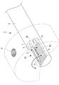
- FIG. 2 is a partial perspective view of a distal end portion showing a state where therapeutic ultrasonic waves are being irradiated by the ultrasonic cauterization system of FIG. 1.
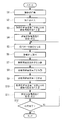
- FIG. 2 is a partial perspective view of a tip portion showing a state in which observation ultrasonic waves are irradiated by the ultrasonic cauterization system of FIG. 1. It is a flowchart explaining the cauterization procedure of the lesioned part by the ultrasonic cauterization system of FIG.
- the ultrasonic ablation system 1 is an ultrasonic endoscope, and includes an ultrasonic ablation device 2, an observation ultrasonic element 3, and an ultrasonic wave according to the present embodiment.
- a sonic ablation device 2 and a driving device (control device) 4 for driving the observation ultrasonic element 3 are provided.
- the ultrasonic ablation device 2 includes a long and narrow insertion portion 5 that can be inserted into a body cavity, and a treatment provided at the distal end of the insertion portion 5. And a channel 7 that is formed over substantially the entire length along the longitudinal axis direction of the insertion portion 5 and into which the observation ultrasonic element 3 is reciprocally moved in the longitudinal axis direction.
- the insertion portion 5 is formed in a tube shape having a soft cross-sectional circular shape, and has a notch portion in which a tip portion is partially cut off by a first plane 8a parallel to the longitudinal axis and a second plane 8b orthogonal to the longitudinal axis.
- the therapeutic ultrasonic element 6 is composed of a plurality of piezoelectric elements (piezoelectric element arrays) 9 arranged in a two-dimensional array along the first plane 8a. By selectively operating the piezoelectric elements 9, The therapeutic ultrasonic waves can be converged at an arbitrary focal position within a three-dimensional irradiation range arranged in a direction orthogonal to the one plane 8a.
- a channel 7 for inserting the observation ultrasonic element 3 is opened in the second plane 8b constituting the cutout portion of the insertion portion 5. Further, an imaging unit 10 that protrudes from the second plane 8b to a position that does not overlap the therapeutic ultrasound irradiation range by the therapeutic ultrasound element 6 and acquires an optical image in a range including the irradiation range as an image signal is provided. Yes. The operation of the imaging unit 10 is controlled by a driving device (control device) 4.
- the observation ultrasonic element 3 can acquire a three-dimensional ultrasonic image by spiral scanning in which the driving device 4 combines swing or rotation driving and linear driving in the longitudinal direction.
- a method of acquiring a three-dimensional ultrasonic image using an observation ultrasonic element is disclosed in, for example, Japanese Patent No. 4343582.
- the channel 7 is formed over the entire length of the insertion portion 5 in the longitudinal axis direction, and accommodates the observation ultrasonic element 3 inserted from the proximal end side so as to be reciprocable in the longitudinal axis direction.
- the front end of the second flat plate 8b can be projected and retracted forward from the opening of the second plane 8b.
- the observation ultrasonic element 3 has a piezoelectric element 11 that emits observation ultrasonic waves in a direction perpendicular to the longitudinal axis of the insertion portion 5 at the tip formed on an elongated tube that can be inserted into the channel 7 around the longitudinal axis. It is equipped to be rotatable.
- the observation ultrasonic element 3 scans the observation ultrasonic wave in a fan-shaped range (radial scan) by rotating the piezoelectric element 11 around the longitudinal axis while emitting the observation ultrasonic wave from the piezoelectric element 11. Can be done.
- the observation ultrasonic element 3 scans the observation ultrasonic wave in a state of protruding from the opening of the channel 7. As shown in FIG. 3, the first ultrasonic wave element 6 for treatment is provided. Since the planes 8a are arranged close to each other, there is no need to emit observation ultrasonic waves over the entire circumference, and the observation ultrasonic waves can be rotated over an angular range that does not interfere with the first plane 8a of the notch. ing.
- the observation ultrasonic element 3 is supported by the channel 7 so as to be reciprocable in the longitudinal axis direction, the observation ultrasonic wave is moved to a three-dimensional region by moving the piezoelectric element 11 in the longitudinal axis direction. Can be scanned.
- a balloon and a water injection mechanism for the inside of the balloon may be disposed at the tip so that ultrasonic vibration can be efficiently transmitted to the living tissue.
- Such a method is known as a balloon method, and is disclosed in, for example, Japanese Patent Application Laid-Open No. 2009-24658.
- the driving device 4 moves the observation ultrasonic element 3 in the longitudinal axis direction of the insertion portion 5, and operates and treats the piezoelectric element 11 provided in the observation ultrasonic element 3.
- the operation of a large number of piezoelectric elements 9 constituting the ultrasonic element 6 is controlled.
- the driving device 4 stops the observation ultrasonic element 3 in a state where the operation of the therapeutic ultrasonic element 6 is stopped.
- the observation ultrasonic wave is emitted from the piezoelectric element 11, and the piezoelectric element 11 is swung or rotated around the longitudinal axis.
- the observation ultrasonic element 3 is moved in the longitudinal axis direction.
- the driving device 4 stops the operation of the piezoelectric element 11 of the observation ultrasonic element 3 and observes the ultrasonic wave.
- the therapeutic ultrasound element 6 is configured with a phase control sequence corresponding to the position of the lesion site X to be cauterized.
- the plurality of piezoelectric elements 9 are actuated to focus the therapeutic ultrasonic waves on the lesion X.
- the imaging unit 10 is operated (step S1) so that the inside of the body cavity can be observed by the image signal of the imaging unit 10.
- the insertion unit 5 is inserted into the body cavity from the distal end side, and the lesion site X to be cauterized is detected by the imaging unit 10.
- the insertion is stopped at the position where the image is taken (step S2). This operation may be performed by the operator observing the intra-body cavity image generated by the image signal of the imaging unit 10, or automatically from the image signal of the imaging unit 10 by the software function or the like. The position may be specified and insertion may be stopped.
- the observation ultrasonic element 3 is driven by the driving device 4 so that the tip of the observation ultrasonic element 3 protrudes forward from the opening of the channel 7 and the piezoelectric element 11 is operated to observe in a fan shape.
- a radial scan is performed at each position in the longitudinal axis direction in order to detect the depth of the lesion site X in particular (step S3).
- the observation ultrasonic wave is scanned over the three-dimensional scanning range, the three-dimensional ultrasonic signal of the biological tissue as the subject can be acquired, and an ultrasonic tomographic image can be generated from the ultrasonic signal. Is displayed on a monitor (not shown) (step S4).
- the user specifies the lesion site X to be cauterized in the three-dimensional ultrasonic tomographic image (step S5).
- coordinates indicating the range of the lesion site X to be cauterized are set, and the drive signals of the piezoelectric elements 9 constituting the therapeutic ultrasonic element 6 for converging the therapeutic ultrasonic waves to the set coordinates are set.
- Is calculated step S6. It should be noted that this lesion site X identification process (step S5 and step S6) can be automatically identified based on an ultrasonic signal by a computer program or the like.
- the observation ultrasonic element 3 When the lesion site X to be cauterized is specified, the observation ultrasonic element 3 is moved to the proximal side in the channel 7 by the driving device 4 and accommodated in the opening. As a result, the observation ultrasonic element 3 is retracted outside the irradiation range of the therapeutic ultrasonic element 6 (step S7). In this state, the drive device 4 operates the therapeutic ultrasonic element 6 according to the calculated drive signal. As a result, the therapeutic ultrasound can be converged at each position of the identified lesion site X, and the lesion site X can be cauterized (step S8).
- the therapeutic ultrasonic element 6 is stopped by the driving device 4 (step S9).
- the observation ultrasonic element 3 is again projected forward (from the distal end side of the insertion portion 5) from the opening by the driving device 4, and is moved in the longitudinal axis direction while scanning the observation ultrasonic wave in a fan shape (step S10). Therefore, the drive device 4 oscillates the observation ultrasonic wave from the observation ultrasonic element 3 to acquire an ultrasonic signal, and generates and displays a three-dimensional ultrasonic tomographic image (step S11). The user determines whether or not the lesion site X has been cauterized sufficiently for treatment.
- step S12 When it is determined that the cauterization has been sufficiently performed, the cauterization is terminated, and when the cauterization has not been sufficiently performed, the processes from step S5 are repeated (step S12). Note that it is also possible to automatically determine whether or not the cauterization sufficient for this treatment has been achieved by a computer program or the like. In this case, a predetermined threshold is provided for the intensity of the ultrasonic signal, and whether or not sufficient cauterization has been achieved is determined based on whether the threshold is higher or lower.
- the observation ultrasonic element 3 when irradiating the observation ultrasonic wave, the observation ultrasonic element 3 protrudes forward from the opening of the channel 7, When irradiating therapeutic ultrasonic waves, the observation ultrasonic element 3 is retracted into the channel 7, so that both the observation ultrasonic waves and the therapeutic ultrasonic waves can be emitted from the same position in the longitudinal axis direction of the insertion portion 5. it can. Therefore, the rigid length of the insertion portion 5 can be significantly reduced as compared with the conventional ultrasonic ablation device in which the observation ultrasonic element 3 and the therapeutic ultrasonic element 6 are arranged side by side in the longitudinal axis direction. There is an advantage that you can.
- the observation ultrasonic element 3 can be easily switched between the irradiation of the observation ultrasonic wave and the irradiation of the therapeutic ultrasonic wave by the appearance and exit of the channel 7, the observation ultrasonic wave irradiation and the therapeutic ultrasonic wave irradiation are performed. Alternately in a short time, even if the relative position of the lesion site X and the ultrasonic ablation device 2 fluctuates during the treatment, the lesion site X can reliably irradiate therapeutic ultrasound. There are advantages.
- the ultrasonic ablation system 1 including the ultrasonic ablation device 2 and the observation ultrasonic element 3 inserted into the channel 7 of the ultrasonic ablation device 2 is illustrated, but instead of this,
- an ultrasonic ablation apparatus in which the observation ultrasonic element 3 is provided at the distal end portion of the ultrasonic ablation apparatus 2 so as to advance and retreat in the longitudinal direction without providing the channel 7 may be adopted.
Landscapes
- Health & Medical Sciences (AREA)
- Life Sciences & Earth Sciences (AREA)
- Surgery (AREA)
- Heart & Thoracic Surgery (AREA)
- Engineering & Computer Science (AREA)
- Biomedical Technology (AREA)
- Nuclear Medicine, Radiotherapy & Molecular Imaging (AREA)
- Medical Informatics (AREA)
- Molecular Biology (AREA)
- Animal Behavior & Ethology (AREA)
- General Health & Medical Sciences (AREA)
- Public Health (AREA)
- Veterinary Medicine (AREA)
- Surgical Instruments (AREA)
- Ultra Sonic Daignosis Equipment (AREA)
Abstract
硬性長を短縮しつつ、超音波による観察と焼灼とを実施することを目的として、本発明に係る超音波焼灼装置(2)は、体腔内に挿入される長尺状の挿入部(5)と、挿入部(5)の先端に設けられ、挿入部(5)の長手軸に交差する方向に、焦点位置に収束する治療用超音波を射出する治療用超音波素子(6)と、挿入部(5)に設けられ、長手軸に直交する方向に観察用超音波を射出し、また、当該観察用超音波の射出方向を長手軸回りに変化させることが可能な観察用超音波素子(3)を、長手軸に沿って挿入可能なチャネル(7)と、を備え、チャネル(7)の挿入部(5)先端側の開口は、治療用超音波の照射範囲よりも、挿入部(5)の基端側に配置され、また、観察用超音波素子(3)がチャネル(5)から突出すると治療用超音波の照射範囲に重なる位置に配置されている。
Description
本発明は、超音波焼灼装置および超音波焼灼システムに関するものである。
超音波内視鏡の観察下で、深部の病変を選択的かつ比較的広範囲に焼灼する超音波焼灼装置が知られている(例えば、特許文献1参照。)。
この超音波焼灼装置は、コンベックス型の超音波探触子を備えた超音波内視鏡と該超音波内視鏡に組み付けられるHIFUアダプタに組み付けられたHIFU超音波素子とを備え、このHIFU超音波素子の焦点位置を任意に変化させる機構を備えている。
この超音波焼灼装置は、コンベックス型の超音波探触子を備えた超音波内視鏡と該超音波内視鏡に組み付けられるHIFUアダプタに組み付けられたHIFU超音波素子とを備え、このHIFU超音波素子の焦点位置を任意に変化させる機構を備えている。
この装置においては、超音波内視鏡により深部の病変を観察して焼酌すべき領域を同定し、同定された領域に焦点位置を一致させるようにHIFU超音波素子の位置を調整して収束超音波により焼酌する。焼酌すべき範囲が広い場合には、焦点位置を変更して複数回焼酌する。
しかしながら、特許文献1の超音波焼灼装置は、コンベックス型の超音波探触子とHIFU超音波素子とを超音波内視鏡の長手軸方向に配列しているため、湾曲部よりも先端側に配置される湾曲できない硬性長が長くなってしまうという不都合がある。
本発明は、上述した事情に鑑みてなされたものであって、硬性長を短縮しつつ、超音波による観察と焼灼とを実施することができる超音波焼灼装置および超音波焼灼システムを提供することを目的としている。
本発明の一態様は、体腔内に挿入される長尺状の挿入部と、該挿入部の先端に設けられ、該挿入部の長手軸に交差する方向に、焦点位置に収束する治療用超音波を射出する治療用超音波素子と、前記挿入部に設けられ、前記長手軸に直交する方向に観察用超音波を射出し、また、当該観察用超音波の射出方向を前記長手軸回りに変化させることが可能な観察用超音波素子を、前記長手軸に沿って挿入可能なチャネルと、を備え、該チャネルの前記挿入部先端側の開口は、前記治療用超音波素子による前記治療用超音波の照射範囲よりも、前記挿入部の基端側に配置され、また、前記観察用超音波素子が前記チャネルから突出すると前記治療用超音波の照射範囲に重なる位置に配置されている超音波焼灼装置である。
また、本発明の他の態様は、上記超音波焼灼装置と、前記観察用超音波素子とを備える超音波焼灼システムである。
さらに、本発明の他の態様は、体腔内に挿入される長尺状の挿入部と、該挿入部の先端に設けられ、該挿入部の長手軸に交差する方向に、焦点位置に収束する治療用超音波を射出する治療用超音波素子と、該治療用超音波素子による前記治療用超音波の照射範囲よりも基端側の位置と、前記照射範囲に重なる位置との間で前記長手軸に沿って移動可能に設けられ、前記長手軸に直交する方向に射出する観察用超音波の射出方向を前記長手軸回りに変化させることが可能な観察用超音波素子と、を備える超音波焼灼装置である。
さらに、本発明の他の態様は、体腔内に挿入される長尺状の挿入部と、該挿入部の先端に設けられ、該挿入部の長手軸に交差する方向に、焦点位置に収束する治療用超音波を射出する治療用超音波素子と、該治療用超音波素子による前記治療用超音波の照射範囲よりも基端側の位置と、前記照射範囲に重なる位置との間で前記長手軸に沿って移動可能に設けられ、前記長手軸に直交する方向に射出する観察用超音波の射出方向を前記長手軸回りに変化させることが可能な観察用超音波素子と、を備える超音波焼灼装置である。
本発明によれば、硬性長を短縮しつつ、超音波による観察と焼灼とを実施することができるという効果を奏する。
本発明の一実施形態に係る超音波焼灼装置2および超音波焼灼システム1について、図面を参照して以下に説明する。
本実施形態に係る超音波焼灼システム1は、図1に示されるように、超音波内視鏡であって、本実施形態に係る超音波焼灼装置2と、観察用超音波素子3と、超音波焼灼装置2および観察用超音波素子3を駆動する駆動装置(制御装置)4とを備えている。
本実施形態に係る超音波焼灼システム1は、図1に示されるように、超音波内視鏡であって、本実施形態に係る超音波焼灼装置2と、観察用超音波素子3と、超音波焼灼装置2および観察用超音波素子3を駆動する駆動装置(制御装置)4とを備えている。
本実施形態に係る超音波焼灼装置2は、図2および図3に示されるように、体腔内に挿入可能な細長い長尺状の挿入部5と、該挿入部5の先端に設けられた治療用超音波素子6と、挿入部5の長手軸方向に沿ってほぼ全長にわたって形成され観察用超音波素子3を長手軸方向に往復動可能に挿入するチャネル7とを備えている。
挿入部5は、軟性の横断面円形のチューブ状に形成され、長手軸に平行な第1平面8aおよび長手軸に直交する第2平面8bによって先端部を部分的に切り落とした形態の切欠部を備えている。
治療用超音波素子6は、第1平面8aに沿って2次元のアレイ状に配列された複数の圧電素子(圧電素子アレイ)9からなり、圧電素子9を選択的に作動させることによって、第1平面8aに直交する方向に配置される3次元的な照射範囲内の任意の焦点位置に、治療用超音波を収束させることができるようになっている。
治療用超音波素子6は、第1平面8aに沿って2次元のアレイ状に配列された複数の圧電素子(圧電素子アレイ)9からなり、圧電素子9を選択的に作動させることによって、第1平面8aに直交する方向に配置される3次元的な照射範囲内の任意の焦点位置に、治療用超音波を収束させることができるようになっている。
また、挿入部5の切欠部を構成している第2平面8bには、観察用超音波素子3を挿入するチャネル7が開口している。また、第2平面8bからは治療用超音波素子6による治療用超音波の照射範囲に重複しない位置に突出し、照射範囲を含む範囲の光学像を画像信号として取得する撮像部10が設けられている。この撮像部10は、駆動装置(制御装置)4によってその動作が制御される。
ここで、観察用超音波素子3は駆動装置4によって揺動もしくは回転駆動と長手方向へのリニア駆動を組み合わせたスパイラルスキャンによって3次元超音波画像を取得することができる。このように、観察用超音波素子を用いて3次元超音波画像を取得する方式については、例えば特許第4343592号に開示されている。
チャネル7は、挿入部5の長手軸方向の全長にわたって形成されており、基端側から挿入された観察用超音波素子3を長手軸方向に往復動可能に収容し、観察用超音波素子3の先端を第2平面8bの開口から前方に出没させることができるようになっている。
観察用超音波素子3は、チャネル7内に挿入可能な細長いチューブ上に形成された先端に、挿入部5の長手軸に直交する方向に観察用超音波を射出する圧電素子11を長手軸回りに回転可能に備えている。観察用超音波素子3は、圧電素子11から観察用超音波を射出しながら圧電素子11を長手軸回りに回転させることで、扇形状の範囲で観察用超音波を走査(ラジアルスキャン)させることができるようになっている。
観察用超音波素子3は、チャネル7の開口から突出させられた状態で、観察用超音波を走査させるが、図3に示されるように、治療用超音波素子6が設けられている第1平面8aが近接して配置されているので、全周にわたって観察用超音波を射出する必要はなく、観察用超音波が切欠部の第1平面8aに干渉しない角度範囲にわたって回転させられるようになっている。
また、観察用超音波素子3は、チャネル7によって長手軸方向に往復動可能に支持されているので、圧電素子11を長手軸方向に移動させることにより、3次元的な領域に観察用超音波を走査させることができるようになっている。
なお、図2において、先端部にバルーンとその内部に対する注水機構とを配置して超音波振動を効率よく生体組織に伝達できるようにしてもよい。このような手法はバルーン法として知られており、例えば特開2009-24658に開示されている。
なお、図2において、先端部にバルーンとその内部に対する注水機構とを配置して超音波振動を効率よく生体組織に伝達できるようにしてもよい。このような手法はバルーン法として知られており、例えば特開2009-24658に開示されている。
駆動装置4は、図3に示されるように、観察用超音波素子3を挿入部5の長手軸方向に移動させるとともに、観察用超音波素子3に備えられた圧電素子11の作動および治療用超音波素子6を構成している多数の圧電素子9の作動を制御するようになっている。
具体的には、駆動装置4は、観察用超音波素子3により超音波断層画像を取得する際には、治療用超音波素子6の作動を停止させた状態で、観察用超音波素子3をチャネル7の開口から、前方の治療用超音波素子6に対向する位置まで突出させるとともに、圧電素子11から観察用超音波を射出させ、圧電素子11を長手軸回りに揺動もしくは回転させながら、観察用超音波素子3を長手軸方向に移動させるようになっている。
具体的には、駆動装置4は、観察用超音波素子3により超音波断層画像を取得する際には、治療用超音波素子6の作動を停止させた状態で、観察用超音波素子3をチャネル7の開口から、前方の治療用超音波素子6に対向する位置まで突出させるとともに、圧電素子11から観察用超音波を射出させ、圧電素子11を長手軸回りに揺動もしくは回転させながら、観察用超音波素子3を長手軸方向に移動させるようになっている。
また、駆動装置4は、治療用超音波素子6により治療用超音波を病変部位Xに照射する場合には、観察用超音波素子3の圧電素子11の作動を停止させるとともに、観察用超音波素子3をチャネル7内に引っ込めて、治療用超音波の照射範囲外に退避させた状態で、焼灼すべき病変部位Xの位置に応じた位相制御シーケンスで治療用超音波素子6を構成している複数の圧電素子9を作動させ、病変部位Xに治療用超音波を収束させるようになっている。
このように構成された本実施形態に係る超音波焼灼システム1の作用について以下に説明する。
図4に示されるように、本実施形態に係る超音波焼灼システム1によって、体腔内の病変部位Xを焼灼するには、以下のステップを行う。先ず、撮像部10を作動させ(ステップS1)、撮像部10の画像信号によって体腔内を観察できるような状態にする。次に、治療用超音波素子6および観察用超音波素子3の作動を停止した状態で、挿入部5を体腔内に先端側から挿入していき、焼灼すべき病変部位Xが撮像部10により撮影される位置で挿入を停止する(ステップS2)。この作業は、操作者が撮像部10の画像信号によって生成される体腔内画像を観察することで行ってもよいし、ソフトウェアの機能等によって撮像部10の画像信号から自動的に病変部位Xの位置を特定して挿入を停止させるようにしてもよい。
図4に示されるように、本実施形態に係る超音波焼灼システム1によって、体腔内の病変部位Xを焼灼するには、以下のステップを行う。先ず、撮像部10を作動させ(ステップS1)、撮像部10の画像信号によって体腔内を観察できるような状態にする。次に、治療用超音波素子6および観察用超音波素子3の作動を停止した状態で、挿入部5を体腔内に先端側から挿入していき、焼灼すべき病変部位Xが撮像部10により撮影される位置で挿入を停止する(ステップS2)。この作業は、操作者が撮像部10の画像信号によって生成される体腔内画像を観察することで行ってもよいし、ソフトウェアの機能等によって撮像部10の画像信号から自動的に病変部位Xの位置を特定して挿入を停止させるようにしてもよい。
この状態で、駆動装置4により観察用超音波素子3を駆動させることで、観察用超音波素子3の先端をチャネル7の開口から前方に突出させ、圧電素子11を作動させて扇形状に観察用超音波を走査させながら、圧電素子11を長手軸方向に移動させることにより、長手軸方向の各位置において、特に病変部位Xの深さを検出すべくラジアルスキャンを実施させる(ステップS3)。
これにより、3次元的な走査範囲にわたって観察用超音波が走査され、被写体である生体組織の3次元的な超音波信号を取得し、当該超音波信号から超音波断層画像を生成することができ、図示しないモニタに表示される(ステップS4)。
これにより、3次元的な走査範囲にわたって観察用超音波が走査され、被写体である生体組織の3次元的な超音波信号を取得し、当該超音波信号から超音波断層画像を生成することができ、図示しないモニタに表示される(ステップS4)。
ユーザは、その3次元的な超音波断層画像において、焼灼すべき病変部位Xを特定する(ステップS5)。これにより、焼灼すべき病変部位Xの範囲を示す座標が設定され、設定された座標に治療用超音波を収束させるための治療用超音波素子6を構成している各圧電素子9の駆動信号が算出される(ステップS6)。なお、この病変部位Xの特定処理(ステップS5およびステップS6)は、コンピュータプログラムなどにより超音波信号に基づいて自動的に特定されるようにすることも可能である。
焼灼すべき病変部位Xが特定されると、駆動装置4により、観察用超音波素子3がチャネル7内を基端側に移動させられて、開口内に収容される。これにより、治療用超音波素子6の照射範囲外に観察用超音波素子3が退避させられる(ステップS7)。
この状態で、駆動装置4は、算出された駆動信号に従って、治療用超音波素子6を作動させる。これにより、特定された病変部位Xの各位置に治療用超音波を収束させて、病変部位Xを焼灼することができる(ステップS8)。
この状態で、駆動装置4は、算出された駆動信号に従って、治療用超音波素子6を作動させる。これにより、特定された病変部位Xの各位置に治療用超音波を収束させて、病変部位Xを焼灼することができる(ステップS8)。
この後に、駆動装置4により治療用超音波素子6を停止させる(ステップS9)。そして、駆動装置4により観察用超音波素子3を再度開口から前方(挿入部5先端側)に突出させ、観察用超音波を扇形状に走査させながら長手軸方向に移動させる(ステップS10)。そこで、駆動装置4により、観察用超音波素子3から観察用超音波を発振させることで超音波信号を取得し、3次元的な超音波断層画像を生成して表示することで(ステップS11)、病変部位Xが、治療に十分に焼灼をされたか否かをユーザに判断させる。
十分に焼灼されたと判定された場合には、焼灼を終了し、十分に焼灼されていない場合には、ステップS5からの工程が繰り返される(ステップS12)。なお、この治療に足る焼灼が成されたか否かを判断するのは、コンピュータプログラムなどにより、自動で判断することも可能である。この場合、超音波信号の強さに対して所定の閾値を設け、当該閾値より高いか低いかで、十分な焼灼が成されたか否かを判断する。
十分に焼灼されたと判定された場合には、焼灼を終了し、十分に焼灼されていない場合には、ステップS5からの工程が繰り返される(ステップS12)。なお、この治療に足る焼灼が成されたか否かを判断するのは、コンピュータプログラムなどにより、自動で判断することも可能である。この場合、超音波信号の強さに対して所定の閾値を設け、当該閾値より高いか低いかで、十分な焼灼が成されたか否かを判断する。
このように、本実施形態に係る超音波焼灼装置2および超音波焼灼システム1によれば、観察用超音波を照射するときには、チャネル7の開口から観察用超音波素子3を前方に突出させ、治療用超音波を照射するときには、チャネル7内に観察用超音波素子3を引っ込めるので、挿入部5の長手軸方向の同一位置から観察用超音波および治療用超音波の両方を射出することができる。したがって、観察用超音波素子3と治療用超音波素子6とを長手軸方向に並べて配置していた従来の超音波焼灼装置と比較して、挿入部5の硬質長を大幅に短縮することができるという利点がある。
また、観察用超音波素子3のチャネル7からの出没によって、観察用超音波の照射と治療用超音波の照射とを簡易に切り替えられるので、観察用超音波の照射と治療用超音波の照射とを短時間で交互に行うことで、処置中に病変部位Xと超音波焼灼装置2との相対位置が変動しても、病変部位Xにより確実に治療用超音波を照射することができるという利点がある。
なお、本実施形態においては、超音波焼灼装置2と、該超音波焼灼装置2のチャネル7に挿入される観察用超音波素子3とを備える超音波焼灼システム1について例示したが、これに代えて、チャネル7を設けることなく、観察用超音波素子3が超音波焼灼装置2の先端部に長手方向に進退可能に設けられた超音波焼灼装置を採用してもよい。
1 超音波焼灼システム
2 超音波焼灼装置
3 観察用超音波素子
4 駆動装置(制御装置)
5 挿入部
6 治療用超音波素子
7 チャネル
9 圧電素子(圧電素子アレイ)
2 超音波焼灼装置
3 観察用超音波素子
4 駆動装置(制御装置)
5 挿入部
6 治療用超音波素子
7 チャネル
9 圧電素子(圧電素子アレイ)
Claims (7)
- 体腔内に挿入される長尺状の挿入部と、
該挿入部の先端に設けられ、該挿入部の長手軸に交差する方向に、焦点位置に収束する治療用超音波を射出する治療用超音波素子と、
前記挿入部に設けられ、前記長手軸に直交する方向に観察用超音波を射出し、また、当該観察用超音波の射出方向を前記長手軸回りに変化させることが可能な観察用超音波素子を、前記長手軸に沿って挿入可能なチャネルと、を備え、
該チャネルの前記挿入部先端側の開口は、
前記治療用超音波の照射範囲よりも、前記挿入部の基端側に配置され、また、
前記観察用超音波素子が前記チャネルから突出すると前記治療用超音波の照射範囲に重なる位置に配置されている
超音波焼灼装置。 - 前記治療用超音波素子が、前記焦点位置を変更可能に構成されている
請求項1に記載の超音波焼灼装置。 - 前記治療用超音波素子が、複数の圧電素子を2次元的に配列した圧電素子アレイにより構成されている
請求項2に記載の超音波焼灼装置。 - 請求項1から請求項3のいずれかに記載の超音波焼灼装置と、
前記観察用超音波素子と、
を備える超音波焼灼システム。 - 前記観察用超音波素子を前記長手軸に沿って移動させる駆動装置と、
を備える請求項4に記載の超音波焼灼システム。 - 前記観察用超音波素子が前記治療用超音波の前記照射範囲に重なる位置に配置されているときには前記治療用超音波素子を停止し、前記観察用超音波素子が前記治療用超音波の前記照射範囲よりも前記基端側に後退した位置に配置されているときには前記治療用超音波素子の作動を許可する制御装置と、
を備える請求項4または請求項5に記載の超音波焼灼システム。 - 体腔内に挿入される長尺状の挿入部と、
該挿入部の先端に設けられ、該挿入部の長手軸に交差する方向に、焦点位置に収束する治療用超音波を射出する治療用超音波素子と、
該治療用超音波素子による前記治療用超音波の照射範囲よりも基端側の位置と、前記照射範囲に重なる位置との間で前記長手軸に沿って移動可能に設けられ、前記長手軸に直交する方向に射出する観察用超音波の射出方向を前記長手軸回りに変化させることが可能な観察用超音波素子と、
を備える超音波焼灼装置。
Priority Applications (1)
| Application Number | Priority Date | Filing Date | Title |
|---|---|---|---|
| PCT/JP2016/082254 WO2018078852A1 (ja) | 2016-10-31 | 2016-10-31 | 超音波焼灼装置および超音波焼灼システム |
Applications Claiming Priority (1)
| Application Number | Priority Date | Filing Date | Title |
|---|---|---|---|
| PCT/JP2016/082254 WO2018078852A1 (ja) | 2016-10-31 | 2016-10-31 | 超音波焼灼装置および超音波焼灼システム |
Publications (1)
| Publication Number | Publication Date |
|---|---|
| WO2018078852A1 true WO2018078852A1 (ja) | 2018-05-03 |
Family
ID=62024534
Family Applications (1)
| Application Number | Title | Priority Date | Filing Date |
|---|---|---|---|
| PCT/JP2016/082254 Ceased WO2018078852A1 (ja) | 2016-10-31 | 2016-10-31 | 超音波焼灼装置および超音波焼灼システム |
Country Status (1)
| Country | Link |
|---|---|
| WO (1) | WO2018078852A1 (ja) |
Citations (6)
| Publication number | Priority date | Publication date | Assignee | Title |
|---|---|---|---|---|
| JPH07227394A (ja) * | 1994-02-21 | 1995-08-29 | Olympus Optical Co Ltd | 超音波診断治療システム |
| JPH07231894A (ja) * | 1994-02-22 | 1995-09-05 | Olympus Optical Co Ltd | 超音波診断治療システム |
| JPH09503926A (ja) * | 1993-07-26 | 1997-04-22 | イネレク | 治療・影像用体腔プローブと、それを用いた治療装置 |
| US6071238A (en) * | 1996-06-28 | 2000-06-06 | Technomed Medical Systems | Therapy probe |
| JP2004167034A (ja) * | 2002-11-21 | 2004-06-17 | Toshiba Corp | 超音波照射装置 |
| WO2013150777A1 (ja) * | 2012-04-05 | 2013-10-10 | テルモ株式会社 | 血管挿入型治療デバイス |
-
2016
- 2016-10-31 WO PCT/JP2016/082254 patent/WO2018078852A1/ja not_active Ceased
Patent Citations (6)
| Publication number | Priority date | Publication date | Assignee | Title |
|---|---|---|---|---|
| JPH09503926A (ja) * | 1993-07-26 | 1997-04-22 | イネレク | 治療・影像用体腔プローブと、それを用いた治療装置 |
| JPH07227394A (ja) * | 1994-02-21 | 1995-08-29 | Olympus Optical Co Ltd | 超音波診断治療システム |
| JPH07231894A (ja) * | 1994-02-22 | 1995-09-05 | Olympus Optical Co Ltd | 超音波診断治療システム |
| US6071238A (en) * | 1996-06-28 | 2000-06-06 | Technomed Medical Systems | Therapy probe |
| JP2004167034A (ja) * | 2002-11-21 | 2004-06-17 | Toshiba Corp | 超音波照射装置 |
| WO2013150777A1 (ja) * | 2012-04-05 | 2013-10-10 | テルモ株式会社 | 血管挿入型治療デバイス |
Similar Documents
| Publication | Publication Date | Title |
|---|---|---|
| EP0659387B1 (en) | Ultrasonic diagnosis and therapy system in which focusing point of therapeutic ultrasonic wave is locked at predetermined position within observation ultrasonic scanning range | |
| JP6560244B2 (ja) | 管腔内ヒストトリプシーを実行するためのシステム及びその動作方法 | |
| JP4295088B2 (ja) | 集束超音波を用いた治療用プローブ | |
| CN1189135C (zh) | 超声波治疗装置 | |
| JP4993271B2 (ja) | 独立に作動されるアブレーション素子を持つアブレーション・アレイ | |
| KR101093734B1 (ko) | 초음파 치료기용 헤드, 초음파 치료기 및 초음파 치료기의 동작 방법 | |
| JP2001046387A (ja) | 超音波治療アプリケータ | |
| KR101849922B1 (ko) | 의료용 초음파 장치 | |
| JP3850094B2 (ja) | 超音波診断治療システムおよび治療用アダプタ | |
| JP2013128731A (ja) | 超音波治療装置及び手術支援システム | |
| CN109431547B (zh) | 多频面阵超声波内镜系统 | |
| JP3514854B2 (ja) | 超音波診断治療システム | |
| JPH07227395A (ja) | 超音波診断治療システム | |
| JP6386384B2 (ja) | 超音波治療装置および超音波治療システム | |
| JP4488288B2 (ja) | 超音波画像診断装置 | |
| JP6297411B2 (ja) | 超音波治療装置及び超音波治療システム | |
| JP2012529962A (ja) | 粘弾性媒質を撮像するための結像系 | |
| JP2012192022A (ja) | 超音波内視鏡及び内視鏡装置 | |
| WO2018078852A1 (ja) | 超音波焼灼装置および超音波焼灼システム | |
| JP3255652B2 (ja) | レーザ装置 | |
| JP2005124920A (ja) | 超音波診断治療装置 | |
| JP4307626B2 (ja) | 超音波診断装置 | |
| JP2015217247A5 (ja) | ||
| JP3641427B2 (ja) | 内視鏡下外科手術用超音波探触子 | |
| JP2004154300A (ja) | 超音波内視鏡の先端部 |
Legal Events
| Date | Code | Title | Description |
|---|---|---|---|
| 121 | Ep: the epo has been informed by wipo that ep was designated in this application |
Ref document number: 16920371 Country of ref document: EP Kind code of ref document: A1 |
|
| NENP | Non-entry into the national phase |
Ref country code: DE |
|
| 122 | Ep: pct application non-entry in european phase |
Ref document number: 16920371 Country of ref document: EP Kind code of ref document: A1 |
|
| NENP | Non-entry into the national phase |
Ref country code: JP |