WO2018076143A1 - Procédé et dispositif de transmission de données dans un réseau ethernet flexible - Google Patents
Procédé et dispositif de transmission de données dans un réseau ethernet flexible Download PDFInfo
- Publication number
- WO2018076143A1 WO2018076143A1 PCT/CN2016/103104 CN2016103104W WO2018076143A1 WO 2018076143 A1 WO2018076143 A1 WO 2018076143A1 CN 2016103104 W CN2016103104 W CN 2016103104W WO 2018076143 A1 WO2018076143 A1 WO 2018076143A1
- Authority
- WO
- WIPO (PCT)
- Prior art keywords
- data
- block
- flexe
- overhead
- data block
- Prior art date
Links
Images


Classifications
-
- H—ELECTRICITY
- H04—ELECTRIC COMMUNICATION TECHNIQUE
- H04L—TRANSMISSION OF DIGITAL INFORMATION, e.g. TELEGRAPHIC COMMUNICATION
- H04L69/00—Network arrangements, protocols or services independent of the application payload and not provided for in the other groups of this subclass
- H04L69/30—Definitions, standards or architectural aspects of layered protocol stacks
- H04L69/32—Architecture of open systems interconnection [OSI] 7-layer type protocol stacks, e.g. the interfaces between the data link level and the physical level
- H04L69/322—Intralayer communication protocols among peer entities or protocol data unit [PDU] definitions
- H04L69/324—Intralayer communication protocols among peer entities or protocol data unit [PDU] definitions in the data link layer [OSI layer 2], e.g. HDLC
-
- H—ELECTRICITY
- H04—ELECTRIC COMMUNICATION TECHNIQUE
- H04L—TRANSMISSION OF DIGITAL INFORMATION, e.g. TELEGRAPHIC COMMUNICATION
- H04L65/00—Network arrangements, protocols or services for supporting real-time applications in data packet communication
- H04L65/40—Support for services or applications
-
- H—ELECTRICITY
- H04—ELECTRIC COMMUNICATION TECHNIQUE
- H04L—TRANSMISSION OF DIGITAL INFORMATION, e.g. TELEGRAPHIC COMMUNICATION
- H04L69/00—Network arrangements, protocols or services independent of the application payload and not provided for in the other groups of this subclass
- H04L69/02—Protocol performance
-
- H—ELECTRICITY
- H04—ELECTRIC COMMUNICATION TECHNIQUE
- H04L—TRANSMISSION OF DIGITAL INFORMATION, e.g. TELEGRAPHIC COMMUNICATION
- H04L69/00—Network arrangements, protocols or services independent of the application payload and not provided for in the other groups of this subclass
- H04L69/30—Definitions, standards or architectural aspects of layered protocol stacks
- H04L69/32—Architecture of open systems interconnection [OSI] 7-layer type protocol stacks, e.g. the interfaces between the data link level and the physical level
- H04L69/322—Intralayer communication protocols among peer entities or protocol data unit [PDU] definitions
- H04L69/323—Intralayer communication protocols among peer entities or protocol data unit [PDU] definitions in the physical layer [OSI layer 1]
-
- H—ELECTRICITY
- H04—ELECTRIC COMMUNICATION TECHNIQUE
- H04L—TRANSMISSION OF DIGITAL INFORMATION, e.g. TELEGRAPHIC COMMUNICATION
- H04L9/00—Cryptographic mechanisms or cryptographic arrangements for secret or secure communications; Network security protocols
- H04L9/40—Network security protocols
-
- H—ELECTRICITY
- H04—ELECTRIC COMMUNICATION TECHNIQUE
- H04L—TRANSMISSION OF DIGITAL INFORMATION, e.g. TELEGRAPHIC COMMUNICATION
- H04L12/00—Data switching networks
- H04L12/28—Data switching networks characterised by path configuration, e.g. LAN [Local Area Networks] or WAN [Wide Area Networks]
- H04L12/40—Bus networks
Definitions
- Embodiments of the present invention relate to the field of information technology, and, more particularly, to a method and apparatus for transmitting data in a flexible Ethernet.
- Ethernet interface standards and the development of Ethernet devices are not synchronized, resulting in a gap between the bandwidth requirements of the Ethernet interface and the capabilities of the interfaces of the actual Ethernet devices.
- the bandwidth of the Ethernet interface in the standard Ethernet interface is known to be a fixed bandwidth. Therefore, when an Ethernet device is connected to an optical interface device, bandwidth resources cannot be effectively utilized.
- the bandwidth of the output data stream of the Medium Access Control (MAC) layer may not match the bandwidth of one or more physical links of the physical layer.
- MAC Medium Access Control
- the Optical Internetworking Forum (English: Flexible Ethernet, referred to as: FlexE) is published in the MAC layer/Physical Coding Sublayer (English: Physical Coding Sublayer, PCS). An adaptation layer is defined between them.
- the adaptation layer enables the transmission rate of the Ethernet interface to match multiple service scenarios.
- a higher bandwidth network processor (English: Network Processor, NP for short) or a forwarding device appears, the maximum performance of the NP or forwarding device can be achieved without waiting for the standard organization to define a new Ethernet interface with higher bandwidth. .
- the transmission rate (transmission or reception) of each physical layer (English: physical device) (English: device) is 100 Gbit/s. :Gbit/s).
- a single PHY device in FlexE cannot support data streams transmitted at a transmission rate higher than 100 Gibb/s.
- the embodiment of the present invention provides a method and a device for transmitting data in a FlexE, which can increase the number of data blocks in each data block subgroup in the data frame to R*N, and increase the number of overhead headers included in each overhead header group to N. Therefore, the data transmission rate can be flexibly adjusted.
- an embodiment of the present invention provides a method for transmitting data in a FlexE, where the method is applied to a physical layer, where the method includes: acquiring a plurality of data blocks, where the plurality of data blocks are sent by L FlexE clients, where L is a positive integer greater than or equal to 1; sending a data frame including the plurality of data blocks to the physical layer device, the data frame has a transmission rate of N*100 gigabits/second Gbit/s, and the data frame includes T data block groups Each of the T data block groups includes M consecutive data block subgroups, each of the M consecutive data block subgroups including R*N consecutive data Block, the data frame further includes T overhead block groups, where the tth overhead block group of the T overhead block groups is sent before the tth data block group of the T data block groups, and the t The cost block group and the t-th data block group are consecutive in the data frame, the t-th cost block group includes N consecutive cost blocks, and the nth cost block in the t
- the number of data blocks in each data block subgroup in the data frame is increased by R*N from 20 specified in the flexible Ethernet implementation protocol 1.0, and the number of overhead headers included in each overhead header group is flexibly
- the number 1 specified in the network implementation protocol 1.0 is increased to N, so that the data transmission rate can be flexibly adjusted.
- the R data blocks in each of the data block subgroups in the tth data block group are in the tth data block group
- the foregoing technical solution can conveniently migrate one overhead block from one PHY device and the data block corresponding to the overhead block to another PHY device, and can conveniently aggregate N data frames with a transmission rate of 100 Gbit/s into A data frame with a transmission rate of N*100 Gbit/s.
- the foregoing technical solution can conveniently migrate one overhead block from one PHY device and the data block corresponding to the overhead block to another PHY device, and can conveniently aggregate N data frames with a transmission rate of 100 Gbit/s into A data frame with a transmission rate of N*100 Gbit/s.
- the M consecutive data blocks in a case where L is greater than or equal to 2, the M consecutive data blocks
- the Gth data block of any H consecutive data block subgroups in the subgroup is sent by H FlexE clients among the L FlexE clients, where H is a positive integer greater than or equal to 2, and H is less than or Equal to L and less than or equal to M, G is a positive integer greater than or equal to 1 and less than or equal to R*N.
- H is a positive integer greater than or equal to 2
- H is less than or Equal to L and less than or equal to M
- G is a positive integer greater than or equal to 1 and less than or equal to R*N.
- the FlexE client indication field includes a first FlexE client indicator subfield and a second FlexE client indicator subfield
- the FlexE overhead block multiframe to which the nth overhead block in the tth overhead block group belongs includes Q FlexE overhead block frames, and each FlexE overhead block frame in the R FlexE overhead block frames in the Q FlexE overhead block frames Carrying the first FlexE client indication subfield, where the gth FlexE overhead block frame in the R FlexE overhead block frame carries a second FlexE client indication subfield, where the number of the R FlexE overhead block frames is
- the first FlexE client indication subfield carried by the r' FlexE overhead block frames is used to indicate a FlexE client that transmits the rthth data block of the R data blocks of each data block subgroup of the tth data block group.
- the first FlexE client indication subfield carried by the overhead block frame is used to refer to A FlexE client of the H FlexE clients transmitting the Gth data block of the H consecutive data block sub-groups, the second FlexE client carried by the g-th FlexE overhead block frame in the R FlexE overhead block frames
- the physical layer device receiving the data frame may according to the second FlexE client indicator carried by the gth FlexE overhead block frame in the R FlexE overhead block frames of each of the H data frames.
- the field determines the order of one of the H FlexE clients of the Gth data block that sent the H consecutive data block sub-groups in the H FlexE clients.
- the Gth data block of the first data block subgroup in the first data block group of the first one of the consecutive H data frames is the H FlexE clients. Sent by the first FlexE customer
- the FlexE client indication field further includes a third FlexE client indication subfield, where the Q FlexE overhead block frames are Each FlexE overhead block frame carries a third FlexE client indication field, and each FlexE overhead block frame in the Q FlexE overhead block frames includes P overhead blocks; the qth of the Q FlexE overhead block frames
- the third FlexE client indication subfield carried by the FlexE overhead block frame is used to indicate whether the FlexE client of the Gth data block of the first data block subgroup in the first data block group of the P data block group is sent
- the first FlexE client of the H FlexE clients wherein the pth data block group of the P data block groups is sent after the pth FlexE overhead block in the qth FlexE overhead block frame, and
- the third FlexE client indication subfield carried by an overhead block indicates that the overhead block group in which the first overhead block of the FlexE overhead block frame to which the overhead block belongs is consecutive and transmitted after the overhead block group
- the Gth data block of the data block group is sent by the first FlexE client of the H FlexE clients, and the next overhead block and the overhead block include (N*P*H-1) overhead blocks.
- the next cost block indicates that the third FlexE client indication field that is carried is continuous with the overhead block group in which the first overhead block of the FlexE overhead block frame to which the next overhead block belongs, and is transmitted after the overhead block group.
- the Gth data block of the data block group is sent by the first FlexE client of the H FlexE customers.
- each N*P*H overhead block includes an overhead block
- the third FlexE client indication subfield carried by the overhead block indicates the first overhead block of the FlexE overhead block frame to which the overhead block belongs.
- the Gth data block of the data block group that is continuously and after the overhead block group is transmitted by the first FlexE client of the H FlexE clients.
- the physical layer device that receives the data frame can facilitate the determination of the data block sent by the first FlexE client of the H FlexE clients.
- the FlexE client indication field included in the FlexE overhead block multiframe to which the nth overhead block in the tth overhead block group belongs includes W FlexE client indication subfields, where the tth overhead block group N cost blocks respectively belong to N FlexE overhead block multiframes, and each FlexE overhead block multiframe in the N FlexE overhead block multiframes includes Q FlexE overhead block frames, and the W FlexE client indicates subfields by the Q W FlexE overhead block frames in the FlexE overhead block frames are carried, and each FlexE client indication subfield in the W1 FlexE client indication subfields in the W FlexE client indication subfield is used to indicate that the tth data is sent a FlexE client of one of the R data blocks in each of the data block subgroups of the block group, or for indicating R of each of the data block subgroups of the tth data block group
- W FlexE client indication subfields where the tth overhead block group N cost blocks respectively belong to N FlexE overhead block multiframes, and each FlexE overhead block multiframe in the N FlexE
- An overhead block can simultaneously indicate that multiple data blocks are sent by a FlexE client and indicate the FlexE client that sent the multiple data blocks.
- the granularity of the data block corresponding to the overhead block is the sum of the granularity of the multiple data blocks.
- each FlexE overhead block multiframe in the N FlexE overhead block multiframes includes Q FlexE overhead block frames.
- the first aspect or any of the possible implementations of the first aspect may be performed by a physical layer device.
- the physical layer device refers to a circuit for implementing physical layer functions.
- the physical layer functions are defined by the Ethernet protocol.
- physical layer functions may include physical layer coding of data frames.
- the physical layer coding can be 8b/10b coding or 64b/66b coding.
- the physical layer device can be a chip Or a network device that includes the chip.
- the chip can be implemented by an application-specific integrated circuit (ASIC) or a field-programmable gate array (FPGA).
- the network device can be a router, a network switch, or a firewall.
- the network device can include an Ethernet interface.
- the Ethernet interface can include the chip.
- the embodiment of the present invention provides a method for transmitting data in a flexible Ethernet FlexE, where the method is applied to a physical layer, where the method includes: receiving a data frame sent by a physical layer device, where the data frame carries from the L Multiple data blocks sent by the FlexE client, the data frame has a transmission rate of N*100 gigabits/second Gbit/s, and the data frame includes T data block groups, and each data block in the T data block group The group includes M consecutive data block sub-groups, each of the M data block sub-groups including R*N consecutive data blocks, the data frame further including T overhead block groups, the T The tth overhead block group in the overhead block group is received before the tth data block group in the T data block group, and the tth overhead block group and the tth data block group are in the data The frame of the tth overhead block includes N consecutive cost blocks, and the FlexE overhead block multiframe to which the nth cost block of the tth overhead block group belongs carries a FlexE overhead block multiframe
- the FlexE client of the data block is one of the L FlexE clients, and the rth data block in the R data blocks in each of the data block subgroups of the t-th data block group is only belonged to one overhead block
- the number of data blocks in each data block subgroup in the data frame is increased by R*N from 20 specified in the flexible Ethernet implementation protocol 1.0, and the number of overhead headers included in each overhead header group is flexibly
- the number 1 specified in the network implementation protocol 1.0 is increased to N, so that the data transmission rate can be flexibly adjusted.
- the R data blocks in each data block subgroup in the block group are the R*(n-1)+1 data blocks to the R* of each data block subgroup in the tth data block group.
- the R data blocks in each of the data block subgroups in the tth data block group are in the tth data block group
- the N*s+n data blocks of each data block subgroup, where s 0, 1, ..., R-1.
- the foregoing technical solution can conveniently migrate one overhead block from one PHY device and the data block corresponding to the overhead block to another PHY device, and can conveniently aggregate N data frames with a transmission rate of 100 Gbit/s into A data frame with a transmission rate of N*100 Gbit/s.
- the M consecutive data blocks in a case where L is greater than or equal to 2, the M consecutive data blocks
- the Gth data block of any H consecutive data block subgroups in the subgroup is sent by H FlexE clients among the L FlexE clients, where H is a positive integer greater than or equal to 2, and H is less than or Equal to L and less than or equal to M, G is a positive integer greater than or equal to 1 and less than or equal to R*N.
- H is a positive integer greater than or equal to 2
- H is less than or Equal to L and less than or equal to M
- G is a positive integer greater than or equal to 1 and less than or equal to R*N.
- the FlexE client indication field includes a first FlexE client indication subfield and a second FlexE client indication subfield
- the FlexE overhead block multiframe to which the nth overhead block in the tth overhead block group belongs includes Q FlexE overhead block frames, and each FlexE overhead block frame in the R FlexE overhead block frames in the Q FlexE overhead block frames Carrying the first FlexE client indication subfield, where the gth FlexE overhead block frame in the R FlexE overhead block frame carries a second FlexE client indication subfield, where the number of the R FlexE overhead block frames is
- the first FlexE client indication subfield carried by the r' FlexE overhead block frames is used to indicate a FlexE client that transmits the rthth data block of the R data blocks of each data block subgroup of the tth data block group.
- the first FlexE client indication subfield carried by the overhead block frame is used to refer to One of the H FlexE clients transmitting the Gth data block of the H consecutive data block sub-groups, the gth FlexE of the R FlexE overhead block frames
- the second FlexE client indication subfield carried by the overhead block frame is used to indicate that one of the H FlexE clients of the Gth data block that sends the H consecutive data block subgroups is in the H FlexE clients.
- the second FlexE client indication subfield carried in the gth FlexE overhead block frame in the R FlexE overhead block frames of each of the H data frames may be determined to send the H consecutive The order of the FlexE clients of the H FlexE clients of the Gth data block of the data block subgroup in the H FlexE clients.
- the Gth data block of the first data block subgroup in the first data block group of the first one of the consecutive H data frames is the H FlexE clients. Sent by the first FlexE customer
- the determining, according to the T overhead block groups, determining, to send, the FlexE of each data block in the multiple data blocks includes: R FlexEs in Q FlexE overhead block frames in the FlexE overhead block multiframe to which the nth overhead block belongs to the tth overhead block group of each of the consecutive H data frames
- the first FlexE client indication subfield carried in the rthth FlexE overhead block frame in the overhead block frame determines the rth data in the R data blocks of each of the data block subgroups in the tth data block group.
- the FlexE client of the block according to the R in the FlexE overhead block frame of the FlexE overhead block multiframe to which the nth overhead block in the tth overhead block group of each of the consecutive H data frames belongs
- the first FlexE client indication subfield carried by the gth FlexE overhead block frame in the FlexE overhead block frame determines one of the H FlexE clients of the Gth data block that sent the H consecutive data block subgroups Customer; based on the tth overhead of each of the consecutive H data frames
- the second FlexE client indication subfield carried in the gth FlexE overhead block frame in the R FlexE overhead block frames in the Q FlexE overhead block frames in the FlexE overhead block multiframe in the block group to which the nth overhead block belongs An order in which the FlexE clients of the H FlexE clients of the Gth data block of the H consecutive data block sub-groups are sent in the H FlexE clients; according to the transmitting the H consecutive data block sub-groups
- the gth FlexE overhead in the R FlexE overhead block frames of each of the H data frames may be used.
- the second FlexE client indication subfield carried by the block frame determines the order of one of the H FlexE clients of the Gth data block that sent the H consecutive data block subgroups in the H FlexE clients.
- the FlexE client indication field further includes a third FlexE client indication subfield, where the Q FlexE overhead block frames are Each FlexE overhead block frame carries a third FlexE client indication field, and each FlexE overhead block frame in the Q FlexE overhead block frames includes P overhead blocks; the qth of the Q FlexE overhead block frames
- the third FlexE client indication subfield carried by the FlexE overhead block frame is used to indicate whether the FlexE client of the Gth data block of the first data block subgroup in the first data block group of the P data block group is sent
- the first FlexE client of the H FlexE clients wherein the pth data block group of the P data block groups is sent after the pth FlexE overhead block in the qth FlexE overhead block frame, and
- the third FlexE client indication subfield carried by an overhead block indicates that the overhead block group in which the first overhead block of the FlexE overhead block frame to which the overhead block belongs is consecutive and transmitted after the overhead block group
- the Gth data block of the data block group is sent by the first FlexE client of the H FlexE clients, and the next overhead block and the overhead block include (N*P*H-1) overhead blocks.
- the next cost block indicates that the third FlexE client indication field that is carried is continuous with the overhead block group in which the first overhead block of the FlexE overhead block frame to which the next overhead block belongs, and is transmitted after the overhead block group.
- the Gth data block of the data block group is sent by the first FlexE client of the H FlexE customers.
- each N*P*H overhead block includes an overhead block
- the third FlexE client indication subfield carried by the overhead block indicates the first overhead block of the FlexE overhead block frame to which the overhead block belongs.
- the Gth data block of the data block group that is continuously and after the overhead block group is transmitted by the first FlexE client of the H FlexE clients. In this way, it is convenient to determine the data block sent by the first of the H FlexE customers.
- the determining, according to the T overhead block groups, determining, to send, the FlexE of each data block in the multiple data blocks includes: determining, according to the first FlexE client indication subfield carried in the r′th FlexE overhead block frame in the R FlexE overhead block frames, the R pieces of each data block subgroup in the tth data block group.
- the FlexE client of the r'th data block in the data block or determine the tth number According to the r'th data block in the R data blocks in each data block subgroup in the block group, the first FlexE carried according to the gth FlexE overhead block frame in the R FlexE overhead block frames
- the customer indication subfield determines one of the H FlexE clients transmitting the Gth data block of the H consecutive data block subgroups, and carries according to the qth FlexE overhead block frame in the Q FlexE overhead block frames
- the third FlexE client indication subfield determines whether a FlexE client transmitting the Gth data block of the first data block subgroup of the first one of the P data block groups is among the H FlexE clients
- the first FlexE client determines the FlexE client that sent the Gth data block of the H consecutive data block subgroups based on the number of the H FlexE clients and the location of the data block sent by the first FlexE client.
- the third FlexE client indication subfield carried by an overhead block indicates that the overhead block group in which the first overhead block of the FlexE overhead block frame to which the overhead block belongs is consecutive and transmitted after the overhead block group
- the Gth data block of the data block group is sent by the first FlexE client of the H FlexE clients, and the next overhead block and the overhead block include (N*P*H-1) overhead blocks.
- the next cost block indicates that the third FlexE client indication field that is carried is continuous with the overhead block group in which the first overhead block of the FlexE overhead block frame to which the next overhead block belongs, and is transmitted after the overhead block group.
- the Gth data block of the data block group is sent by the first FlexE client of the H FlexE customers.
- each N*P*H overhead block includes an overhead block
- the third FlexE client indication subfield carried by the overhead block indicates the first overhead block of the FlexE overhead block frame to which the overhead block belongs.
- the Gth data block of the data block group that is continuously and after the overhead block group is transmitted by the first FlexE client of the H FlexE clients. In this way, it is convenient to determine the data block sent by the first of the H FlexE customers.
- the The FlexE client indication field included in the FlexE overhead block multiframe to which the nth overhead block belongs to the W overhead block group includes W FlexE client indication subfields, and the N overhead blocks in the tth overhead block group belong to N FlexE overhead block multiframes, each of the FlexE overhead block multiframes comprising Q FlexE overhead block frames, the W FlexE client indication subfields being in the Q FlexE overhead block frames W FlexE overhead block frames are carried, and each FlexE client indication subfield in the W1 FlexE client indication subfields in the W FlexE client indication subfield is used to indicate to send each of the tth data block groups One FlexE client of one of the R data blocks in the data block subgroup, or used to indicate the tth data block One of the R data blocks in each data block subgroup in the group is idle, and each of the W FlexE clients in the subfield indicates the FlexE client indication
- a FlexE client for indicating to send a plurality of data blocks of R data blocks in each of the data block subgroups of the t-th data block group, or for indicating each of the t-th data block groups
- An overhead block can simultaneously indicate that multiple data blocks are sent by a FlexE client and indicate the FlexE client that sent the multiple data blocks.
- the granularity of the data block corresponding to the overhead block is the sum of the granularity of the multiple data blocks.
- the N cost blocks in t overhead block groups belong to N FlexE overhead block multiframes, and each FlexE overhead block multiframe in the N FlexE overhead block multiframes includes Q FlexE overhead block frames, the Q FlexEs
- the FlexE overhead block multiframe carried in one data frame is extended to N*K.
- the second aspect or any of the possible implementations of the second aspect may be performed by a physical layer device.
- the physical layer device refers to a circuit for implementing physical layer functions.
- the physical layer functions are defined by the Ethernet protocol.
- physical layer functions may include physical layer coding of data frames.
- the physical layer coding can be 8b/10b coding or 64b/66b coding.
- the physical layer device can be a chip or a network device including the chip.
- the chip can be implemented by an application-specific integrated circuit (ASIC) or a field-programmable gate array (FPGA).
- the network device can be a router, a network switch, or a firewall.
- the network device can include an Ethernet interface.
- the Ethernet interface can include the chip.
- an embodiment of the present invention provides a method for transmitting data in a flexible Ethernet FlexE, where the method is applied to a physical layer, where the method includes: receiving, by using a first physical layer device PHY device, a first data frame, where the first The transmission rate of a data frame is N*100 gigabits/second Gbit/s, wherein the first data frame carries multiple data blocks from L FlexE clients, and the first data frame includes T first data blocks.
- each of the first data block groups of the T first data block groups includes M consecutive first data block subgroups, each of the first data blocks of the M consecutive first data block subgroups
- the sub-group includes R*N consecutive data blocks
- the first data frame further includes T first overhead block groups, where the tth first overhead block group in the T first overhead block groups precedes the T
- the tth first data block group in the first data block group is received, and the tth first power block group and the tth first data block group are consecutive in the first data frame
- the tth first overhead block group includes N consecutive overhead blocks, and the nth overhead block in the tth first overhead block group belongs to
- the FlexE client block indication field is carried in the FlexE overhead block multi-frame, and the FlexE client indication field carried in the FlexE overhead block multiframe to which the nth cost block in the t-th first overhead block group belongs is used to indicate that the t-th is sent.
- a FlexE client of the rth data block of the R data blocks in each of the first data block groups, or for indicating each of the tth first data block groups The rth data block in the R data blocks in the first data block subgroup is idle, and the R data blocks in each of the first data block subgroups in the tth first data block group are sent.
- the FlexE client of the rth data block is one of the L FlexE clients, and the rth data in the R data blocks in each of the first data block subgroups of the tth first data block group
- the block is indicated by only the FlexE client indication field carried by the FlexE overhead block multiframe to which the overhead block belongs, and each data block in the first data frame contains a number of bits equal to each of the overhead blocks in the first data frame.
- the R data blocks in each of the t data block groups are the t th first data blocks a first R*(n-1)+1 data block to a R*n data block of each first data block subgroup in the group; or each data block in the t first data block group
- the foregoing technical solution can conveniently migrate one overhead block from one PHY device and the data block corresponding to the overhead block to another PHY device, and can conveniently aggregate N data frames with a transmission rate of 100 Gbit/s into A data frame with a transmission rate of N*100 Gbit/s.
- the foregoing technical solution can conveniently migrate one overhead block from one PHY device and the data block corresponding to the overhead block to another PHY device, and can conveniently aggregate N data frames with a transmission rate of 100 Gbit/s into A data frame with a transmission rate of N*100 Gbit/s.
- the third aspect or any of the possible implementations of the third aspect may be performed by a network device.
- the network device can be a router, a network switch, or a firewall.
- the network device can include an Ethernet interface.
- the Ethernet interface can include a physical layer device.
- the physical layer device refers to a circuit for implementing physical layer functions.
- the physical layer functions are defined by the Ethernet protocol.
- physical layer functions may include physical layer coding of data frames.
- the physical layer coding can be 8b/10b coding or 64b/66b coding.
- the physical layer device can be a chip.
- the chip can be implemented by ASIC or FPGA.
- the network device includes the first PHY device and the Y PHY devices.
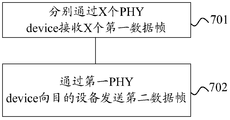
- an embodiment of the present invention provides a method for transmitting data in a flexible Ethernet FlexE, where the method is applied to a physical layer, where the method includes: receiving, by using X physical layer device PHY devices, X first data frames, where The xth PHY device of the X PHY devices is configured to receive the xth first data frame in the X first data frames, where the transmission rate of the xth first data frame is N x *100 ⁇ Bits/sec Gbit/s, the X first data frames carrying a plurality of data blocks from L FlexE clients, the xth first data frame of the X first data frames including T first data frames a block group, each of the first data block groups of the T first data block groups includes M consecutive first data block sub-groups, each of the first data blocks of the M consecutive first data blocks The block subgroup includes R*N x consecutive data blocks, where the xth first data frame further includes T first overhead block groups, and the tth first overhead block in the T first overhead block groups The group
- the FlexE client of the data block is one of the L FlexE clients, and the rth data block of the R data blocks in each of the first data block subgroups of the tth first data block group is only
- R transmitting a second data frame to the destination device by the first PHY device, wherein the second data frame
- the transmission rate is N*100 Gbit/s
- the second data frame carries multiple data blocks from E FlexE clients of the L FlexE clients
- the second data frame includes T second data block groups.
- Each second data block group of the T second data block groups includes M consecutive second data block sub-groups, each of the M consecutive second data block sub-groups
- the group includes R*N consecutive data blocks
- the yth second data frame further includes T second overhead block groups, where the tth second overhead block group of the T second overhead block groups precedes The tth second data block group of the T second data block groups is sent, and the tth second overhead block group and the tth second data block group are consecutive in the data frame,
- the first The t second overhead block groups include N consecutive overhead blocks
- the FlexE overhead block multiframe to which the nth overhead block in the tth second overhead block group belongs carries a FlexE client indication field
- the tth second The FlexE client indication field carried by the FlexE overhead block multiframe to which the nth cost block in the overhead block group belongs is used to indicate that R of each second data block subgroup in the tth second data block group is sent.
- the FlexE client that sends the rth data block of the R data blocks in each of the second data block subgroups of the tth second data block group is one of the E FlexE clients,
- the rth data block of the R data blocks in each of the second data block subgroups of the tth second data block group is only used by the FlexE client indication field carried by the FlexE overhead block multiframe to which the overhead block belongs.
- each data block in the second data frame includes a number of bits equal to each of the second data frames
- the R data blocks in each of the t first data block groups are the t th first data blocks a first R*(n x -1)+1 data block to a R*n x data block of each first data block subgroup in the group; or each data in the t first data block groups
- the foregoing technical solution can conveniently migrate one overhead block from one PHY device and the data block corresponding to the overhead block to another PHY device, and can conveniently aggregate N data frames with a transmission rate of 100 Gbit/s into A data frame with a transmission rate of N*100 Gbit/s. .
- the foregoing technical solution can conveniently migrate one overhead block from one PHY device and the data block corresponding to the overhead block to another PHY device, and can conveniently aggregate N data frames with a transmission rate of 100 Gbit/s into A data frame with a transmission rate of N*100 Gbit/s.
- the fourth aspect or any of the possible implementations of the fourth aspect may be performed by a network device.
- the network device can be a router, a network switch, or a firewall.
- the network device can include an Ethernet interface.
- the Ethernet interface can include a physical layer device.
- the physical layer device refers to a circuit for implementing physical layer functions.
- the physical layer functions are defined by the Ethernet protocol.
- physical layer functions may include physical layer coding of data frames.
- the physical layer coding can be 8b/10b coding or 64b/66b coding.
- the physical layer device can be a chip.
- the chip can be implemented by ASIC or FPGA.
- the network device includes the X PHY devices and the first PHY device.
- an embodiment of the present invention provides a method for transmitting data in a flexible Ethernet FlexE, where the method is applied to a physical layer, where the method includes: receiving, by using X physical layer device PHY devices, X first data frames, where The xth PHY device of the X PHY devices is configured to receive the xth first data frame in the X first data frames, where the transmission rate of the xth first data frame is N x *100 ⁇ Bits/sec Gbit/s, the X first data frames carrying a plurality of data blocks from L FlexE clients, the xth first data frame of the X first data frames including T first data frames a block group, each of the first data block groups of the T first data block groups includes M consecutive first data block sub-groups, each of the first data blocks of the M consecutive first data blocks The block subgroup includes R*N x consecutive data blocks, where the xth first data frame further includes T first overhead block groups, and the tth first overhead block in the T first overhead block groups The group
- the FlexE client of the r data blocks is one of the L FlexE clients, and the rth data block of the R data blocks in each of the first data block subgroups of the tth first data block group is only Indicated by the FlexE client indication field carried by the FlexE overhead block multiframe to which the overhead block belongs, each number in the xth first data frame
- the yth PHY device of the Y PHY devices is configured to receive the yth second data frame of the Y second data frames, where the transmission rate of the yth second data frame is N y *100 Gbit/
- the above technical solution can convert X data frames into Y data frames. For example, in the case where X is greater than Y, the X first data frames may be aggregated into Y second data frames. In the case where X is less than Y, the X first data frames may be expanded into Y second data frames. In addition, the foregoing technical solution may also migrate multiple data blocks in one data frame of the X data frames and an overhead block corresponding to the data blocks to another data frame.
- the R data blocks in each of the t data block groups are the t th first data blocks a first R*(n x -1)+1 data block to a R*n x data block of each first data block subgroup in the group; or each data in the t first data block groups
- the foregoing technical solution can conveniently migrate one overhead block from one PHY device and the data block corresponding to the overhead block to another PHY device, and can conveniently aggregate N data frames with a transmission rate of 100 Gbit/s into A data frame with a transmission rate of N*100 Gbit/s.
- the foregoing technical solution can conveniently migrate one overhead block from one PHY device and the data block corresponding to the overhead block to another PHY device, and can conveniently aggregate N data frames with a transmission rate of 100 Gbit/s into A data frame with a transmission rate of N*100 Gbit/s.
- the network device can be a router, a network switch, or a firewall.
- the network device can include an Ethernet interface.
- the Ethernet interface can include a physical layer device.
- the physical layer device refers to a circuit for implementing physical layer functions.
- the physical layer functions are defined by the Ethernet protocol.
- physical layer functions may include physical layer coding of data frames.
- the physical layer coding can be 8b/10b coding or 64b/66b coding.
- the physical layer device can be a chip.
- the chip can be implemented by ASIC or FPGA.
- the network device includes the X PHY devices and the Y PHY devices.
- the embodiment of the present invention further provides a physical layer device, where the physical layer device includes A unit of the first aspect or any of the possible implementations of the first aspect.
- the embodiment of the present invention further provides a physical layer device, where the physical layer device includes a unit that performs any of the possible implementations of the second aspect or the second aspect.
- the embodiment of the present invention further provides a network device, where the network device includes a unit that performs any one of the possible implementations of the third aspect or the third aspect.
- the ninth aspect the embodiment of the present invention further provides a network device, where the network device includes a unit that performs any of the possible implementations of the fourth aspect or the fourth aspect.
- the embodiment of the present invention further provides a network device, where the network device includes a unit that implements any possible implementation manner of the fifth aspect or the fifth aspect.
- Figure 1 is a schematic diagram of a data stream at a transmission rate of 100 Gbit/s.
- FIG. 2 is a schematic flowchart of a method for transmitting data in a FlexE according to an embodiment of the present invention.
- FIG. 3 is a schematic diagram of a data frame provided in accordance with an embodiment of the present invention.
- FIG. 4 is a schematic diagram of another partial data block sub-group according to an embodiment of the present invention.
- FIG. 5 is a schematic diagram of another data frame according to an embodiment of the present invention.
- FIG. 6 is a schematic flowchart of another method for transmitting data in a FlexE according to an embodiment of the present invention.
- FIG. 7 is a diagram of a method for transmitting data in a flexible Ethernet FlexE according to an embodiment of the present invention.
- FIG. 8 is a diagram of a method for transmitting data in a flexible Ethernet FlexE according to an embodiment of the present invention.
- FIG. 9 is a schematic diagram of an embodiment of converting two first data frames into two second data frames according to an embodiment of the present invention.
- FIG. 10 is a schematic diagram of an embodiment of converting two first data frames into one second data frame according to an embodiment of the present invention.
- FIG. 11 is a schematic diagram of converting four first data frames into two second data frames according to an embodiment of the present invention.
- FIG. 12 is a structural block diagram of a physical layer device according to an embodiment of the present invention.
- FIG. 13 is a structural block diagram of a physical layer device according to an embodiment of the present invention.
- FIG. 14 is a structural block diagram of a network device according to an embodiment of the present invention.
- FIG. 15 is a structural block diagram of a network device according to an embodiment of the present invention.
- FIG. 16 is a structural block diagram of a network device according to an embodiment of the present invention.
- a and B consecutively mean that when A and B are transmitted, no other data is transmitted between A and B.
- the overhead block group is continuous with the data block, and when the overhead block group and the data block are transmitted, no other data is transmitted between the overhead block group and the data block.
- B after A or B after A means that the transmission of B occurs after the transmission of A.
- a data block group after an overhead block group means that the transmission of the data block group occurs after the overhead block group.
- First in this application refers to an element that is first transmitted in a set.
- the first overhead block of the overhead block group refers to the overhead block that is first transmitted in the overhead block group.
- the first data block of a data block group refers to the first data block in the data block group.
- the transmission of data in FlexE is based on a time division multiplexing mechanism. Specifically, the time domain resource occupied by the PHY device whose transmission rate is 100 Gbit/s can be divided into 20 time slots. In each of these 20 time slots, the transmission rate of the PHY device is 5 Gbit/s.
- the PHY device can send one block of data in one time slot.
- a FlexE client corresponds to one or more time slots. That is to say, when transmitting data of a FlexE client, it may take one time slot or multiple time slots.
- the data of the FlexE customer may be data sent by the FlexE client or data received by the FlexE client.
- 20 slots in the time domain resource of the PHY device may correspond to one FlexE client or multiple FlexE clients.
- 20 time slots in the time domain resource of the PHY device can be used only for transmitting data of one FlexE client, and can also be used for transmission. Data for multiple FlexE customers.
- the PHY device After obtaining the data block of a FlexE client, the PHY device can send the data block of the FlexE client using the time slot corresponding to the FlexE client.
- Figure 1 is a schematic diagram of a data stream at a transmission rate of 100 Gbit/s.
- Figure 1 shows a portion of a data stream with a transmission rate of 100 Gbit/s instead of the entire data stream.
- a data stream with a transmission rate of 100 Gbit/s is composed of a data block and an overhead header (English: Overhead, OH for short).
- "*" in the present application means a multiplication sign. Specifically, as shown in FIG. 1, there is one OH before every 20*1023 consecutive data blocks, and the OH is adjacent to the 20*1023 data blocks. That is, an OH is transmitted before 20*1023 consecutive data blocks are transmitted. There are no other data blocks or OHs transmitted between the OH and the 20 1023 consecutive data blocks.
- Eight OHs form a FlexE overhead header (English: Overhead frame).
- the 32 FlexE overhead header frames form a FlexE overhead header multiframe (English: Overhead Multiframe).
- the FlexE overhead header multiframe includes a FlexE client indication field, the FlexE client indication field is used to indicate the FlexE client to which each of the 20*1023 data blocks belongs.
- the FlexE client to which the data block belongs is the FlexE client that will receive the data block.
- the device receiving the data stream can determine the data block sent by the same FlexE client according to the received FlexE overhead header multiframe, and send the data block sent by the same FlexE client to the same target device.
- the FlexE overhead header multiframe may also include other fields.
- the specific content of each field in the FlexE overhead header multiframe can be referred to in the flexible Ethernet implementation protocol 1.0 (English: Flex Ethernet 1.0 Implementation Agreement), and need not be described here.
- Each of the 20*1023 data blocks may be a 64-bit (English:bit)/66-bit encoded data block.
- the data blocks referred to in the embodiments of the present invention all refer to the encoded data blocks.
- the data blocks referred to in the embodiments of the present invention may all be data blocks encoded by a physical coding sublayer circuit defined by an Ethernet protocol.
- the transmitting device sends the data block according to the corresponding relationship between the time slot and the FlexE client. In the case where the correspondence between the time slot and the FlexE client is fixed, the time slots in the 20 time slots included in each cycle occupied by the data block from the same FlexE client are fixed. 20 data blocks are transmitted in each cycle.
- the 20 time slots included in each cycle are the 1st to 20th time slots, respectively.
- the 1st to 20th time slots are used to transmit the 1st to 20th data blocks, respectively.
- the first, third, fifth, and seventh data blocks are all data blocks from FlexE client 1.
- the 2nd, 4th, 6th, and 8th data blocks are all data blocks from FlexE Client 2.
- the period in this application refers to the transmission period of one PHY device.
- One transmission period of one PHY device includes 20 slots.
- FIG. 2 is a schematic flowchart of a method for transmitting data in a FlexE according to an embodiment of the present invention. This method is applied to the physical layer.
- a data frame that includes the multiple data blocks, where the data frame has a transmission rate of N*100 gigabits/second Gbit/s, and the data frame includes T data block groups, and the T data blocks
- Each data block group in the group includes M consecutive data block sub-groups, and each of the M consecutive data block sub-groups includes R*N consecutive data blocks
- the data frame is further Include T overhead block groups, the t-th cost block group in the T-th cost block group is sent before the t-th data block group in the T data block group, and the t-th cost block group and the The t-th data block group is contiguous in the data frame, the t-th cost block group includes N consecutive cost blocks, and the FlexE cost block block to which the n-th cost block in the t-th cost block group belongs
- the frame carries a FlexE client indication field, and the FlexE client indication field carried in the FlexE overhead block multiframe to which the nth overhead block in the tth overhead block
- a FlexE client of the rth data block of the R data blocks in the data block subgroup or used to indicate the tth data block group
- the rth data block of the R data blocks in each data block subgroup is idle, and the rth of the R data blocks in each of the data block subgroups of the tth data block group is transmitted.
- the FlexE client of the data block is one of the L FlexE clients, and the rth data block in the R data blocks in each of the data block subgroups of the t-th data block group is only belonged to one overhead block
- the physical layer device determines, according to the T overhead block groups in the received data frame, a client to which each data block in the data frame belongs.
- the number of data blocks in each data block subgroup in the data frame is increased from 20 specified in the flexible Ethernet implementation protocol 1.0 to R*N, and the overhead header included in each overhead header group.
- the number is increased to N by the 1 specified in the Flexible Ethernet Implementation Protocol 1.0, so that the data transmission rate can be flexibly adjusted.
- the data blocks in the data frame in the method shown in Figure 2 may be 64/66 bit encoded.
- the overhead block in the method shown in Figure 2 can also be 64/66 bit encoded.
- Step 201 and step 202 of the method shown in Figure 2 can be performed by a physical layer device.
- Physical layer A device is a circuit used to implement physical layer functions.
- the physical layer functions are defined by the Ethernet protocol.
- physical layer functions may include physical layer coding of data frames.
- the physical layer coding can be 8b/10b coding or 64b/66b coding.
- the physical layer device can be a chip or a network device including the chip.
- the chip can be implemented by an application-specific integrated circuit (ASIC) or a field-programmable gate array (FPGA).
- the network device can be a router, a network switch, or a firewall.
- the network device can include an Ethernet interface.
- the Ethernet interface can include the chip.
- the physical layer device performing step 201 and step 202 may be referred to as a "first physical layer device.”
- the physical layer device referred to in steps 202 and 203 is the same as the first physical layer device.
- the physical layer device mentioned in step 202 and step 203 may be referred to as a "second physical layer device.”
- the M data block sub-groups are continuously transmitted, and when M data block sub-groups are transmitted, no other data is transmitted between the M data block sub-groups.
- M consecutive data block subgroups refer to two adjacent data block subgroups. When two adjacent sub-blocks of data are transmitted, no other data is transmitted between the adjacent sub-groups of two data blocks.
- M consecutive data block sub-groups include data block sub-group 1, data block sub-group 2, and data block sub-group 3.
- the data block subgroup 1 is sent first, and the data block subgroup 3 is sent last.
- Data block subgroup 1 and data block subgroup 2 are adjacent. There is no other transmitted data between the data block subgroup 1 and the data block subgroup 2. There is no other transmitted data between the data block subgroup 3 and the data block subgroup 3.
- FIG. 3 is a schematic diagram of a data frame provided in accordance with an embodiment of the present invention.
- the data frame structure shown in Figure 3 is part of a complete data frame.
- the data frame is transmitted and the transmission rate is 200 Gbit/s.
- N is 2
- n is 1 and 2
- R is 20.
- each of the overhead block groups in the data frame includes 2 overhead blocks. Adjacent to each of the overhead block groups in the data frame are 1023 data block subgroups, and each data block subgroup includes 40 numbers. According to the block.
- the FlexE overhead block multiframe may also include other fields. The specific content of each field in the FlexE overhead block multiframe can be referred to the description of the FlexE overhead header multiframe in the Flexible Ethernet Implementation Protocol 1.0, and need not be described here.
- the foregoing technical solution can conveniently migrate one overhead block from one PHY device and the data block corresponding to the overhead block to another PHY device, and can conveniently aggregate N data frames with a transmission rate of 100 Gbit/s into A data frame with a transmission rate of N*100 Gbit/s.
- the nth overhead block may be referred to as corresponding to the R*(n-1)+1th data block to the R*nth data block.
- Each overhead block group in the data frame includes 2 overhead blocks. Adjacent to each of the overhead block groups in the data frame are 1023 data block sub-groups, and each data block sub-group includes 40 data blocks.
- the first one of the two overhead blocks ie, the overhead block numbered 0
- the first data block subgroup ie, the data block subgroup numbered 0
- 20 data blocks ie data blocks numbered 0 to 19
- the second overhead block (ie, the overhead block numbered 1) corresponds to the 21-40th data block of the first data block subgroup (ie, the data blocks numbered 20 to 39).
- first overhead block also corresponds to the first 20th data block in the second data block subgroup (not shown), and the second overhead block also corresponds to the second data block.
- Groups 21-40 data blocks (not shown), and so on.
- the first overhead block corresponds to the 1-20th data block in each data block subgroup, and the second overhead block corresponds to the 21-40th data block of each data block subgroup.
- each overhead block group in the data frame includes 4 overhead blocks, and each data block sub-group includes 80 data blocks.
- the first of the four overhead blocks corresponds to the first 20th data block of each data block subgroup.
- the second of the four overhead blocks corresponds to the 21-40th data block of each data block subgroup.
- the third of the four overhead blocks corresponds to the 41st to 60th data blocks of each data block subgroup.
- the fourth of the four overhead blocks corresponds to the 61st to 80th data blocks of each data block subgroup.
- the FlexE overhead block multiframe may also include other fields.
- the FlexE For details about the fields in the overhead block multiframe, refer to the description of the FlexE overhead header multiframe in the Flexible Ethernet Implementation Protocol 1.0, and it is not necessary to repeat them here.
- the foregoing technical solution can conveniently migrate one overhead block from one PHY device and the data block corresponding to the overhead block to another PHY device, and can conveniently aggregate N data frames with a transmission rate of 100 Gbit/s into A data frame with a transmission rate of N*100 Gbit/s.
- the nth overhead block may be referred to as the N*s+nth data block.
- each overhead block group in the data frame includes two overhead blocks. Adjacent to each of the overhead block groups in the data frame are 1023 data block sub-groups, and each data block sub-group includes 40 data blocks. As shown in FIG. 3, the first one of the two overhead blocks (ie, the overhead block numbered 0) corresponds to the first of the first data block sub-group (ie, the data block sub-group numbered 0). , 3, 5, ..., 39 data blocks (ie blocks of numbers 0, 2, ..., 38).
- the second overhead block of the two overhead blocks corresponds to the 2nd, 4th, 6th, 8th, ..., 40th data blocks in the first data block subgroup (ie, the number is 1,3,...,39 data blocks).
- the first overhead block also corresponds to the first, third, fifth, ..., 39 data blocks (not shown) in the second data block subgroup
- the second overhead block also corresponds to The second, fourth, sixth, eighth, ..., 40 data blocks of the second data block subgroup (not shown), and so on.
- the first cost block corresponds to the first, third, fifth, ..., 39 data blocks in each data block subgroup.
- the second overhead block corresponds to the 2nd, 4th, 6th, 8th, ..., 40th data blocks of each data block subgroup.
- each overhead block group in the data frame includes 4 overhead blocks
- each data block sub-group includes 80 data blocks.
- the first of the four overhead blocks corresponds to the first, fifth, ninth, ..., 73, 77 data blocks of each data block subgroup
- the second overhead block corresponds to each data block subgroup. 2, 6, 9, ..., 74, 78 data blocks
- the third overhead block corresponds to the 3rd, 7th, 11th, ..., 75th, 79th data block of each data block subgroup
- the fourth The overhead block corresponds to the 4th, 8th, 12th, ..., 76th, 80th data blocks of each data block subgroup.
- the Gth data block of the H consecutive data block subgroups of the M consecutive data block subgroups is the L Transmitted by H FlexE clients in a FlexE customer, where H is a positive integer greater than or equal to 2, H is less than or equal to L and less than or equal to M, and G is a positive integer greater than or equal to 1 and less than or equal to R*N .
- H is a positive integer greater than or equal to 2
- H is less than or equal to L and less than or equal to M
- G is a positive integer greater than or equal to 1 and less than or equal to R*N .
- the transmission rate of each time slot is 5/H Gbit/s, so that a smaller granularity of transmission rate can be supported.
- the first physical layer device acquires five or more The data transmitted by the FlexE client, then the data blocks in the same location in the five consecutive sub-blocks of data can be sent to five FlexE clients respectively.
- the data blocks in the same location in the five consecutive sub-blocks of data can be sent to five FlexE clients respectively.
- FIG. 4 Please refer to the embodiment shown in FIG. 4.
- FIG. 4 is a schematic diagram of another partial data block sub-group according to an embodiment of the present invention.
- the data block subgroup 0 to the data block subgroup 4 shown in FIG. 4 may be the data block subgroup 0 to the data block subgroup 4 in any one of the data block groups shown in FIG.
- the third data block of the data block subgroup 0 ie, the data block numbered 2 is the data block sent by the FlexE client 1
- the third data block of the data block subgroup 1 ie, the number is
- the data block of 2 is the data block sent by FlexE client 2
- the third data block of data block subgroup 2 (ie the data block numbered 2) is the data block sent by FlexE client 3, and the data block subgroup 3
- the three data blocks are the data blocks sent by the FlexE client 4, and the third data block of the data block subgroup 4 (ie, the data block numbered 2) is the data block sent by the FlexE client 5.
- the other data blocks shown in Figure 4 can be either data blocks sent by any FlexE client or free data blocks.
- the data blocks in the data block subgroups 5 to 1023 are also transmitted in the format shown in the data block subgroup 0 to the data block subgroup 4 as shown in FIG. That is, the third data block of the data block subgroup 5 (ie, the data block numbered 2) is the data block sent by the FlexE client 1, and the third data block of the data block subgroup 6 (ie, the data block numbered 2). ) is the data block sent by FlexE client 2, the third data block of data block subgroup 7 (ie, the data block numbered 2) is the data block sent by FlexE client 3, and the third data block of data block subgroup 8. (ie the data block numbered 2) is the data block sent by the FlexE client 4, the third data block of the data block subgroup 9 (ie the data block numbered 2) is the data block sent by the FlexE client 5, and so on. .
- the transmission rate of each time slot is 1 Gbit/s.
- the FlexE client indication field includes a first FlexE client indication subfield and a second FlexE client indication subfield.
- the FlexE overhead block multiframe to which the nth overhead block in the tth overhead block group belongs includes Q FlexE overhead block frames.
- Each FlexE overhead block frame of the R FlexE overhead block frames in the Q FlexE overhead block frames carries a first FlexE client indication subfield
- the gth FlexE overhead block frame in the R FlexE overhead block frames carries A second FlexE client indicates a subfield.
- the first FlexE client indication subfield carried in the r′th FlexE overhead block frame in the R FlexE overhead block frames is used to indicate that the R data blocks of each data block subgroup in the tth data block group are sent.
- the block is free.
- the first FlexE client indication subfield carried by the gth FlexE overhead block frame in the R FlexE overhead block frames is used to indicate the H FlexE clients that send the Gth data block of the H consecutive data block subgroups A FlexE customer.
- the second FlexE client indication subfield carried by the gth FlexE overhead block frame in the R FlexE overhead block frames is used to indicate the H FlexE clients of the Gth data block that sends the H consecutive data block subgroups The order of a FlexE customer in the H FlexE customers.
- the Gth data block of the first data block subgroup in the first data block group of the first one of the consecutive H data frames is the H FlexE clients.
- the second physical layer device may be configured according to each of the received H consecutive data frames.
- the first FlexE client carried by the gth FlexE overhead block frame in the R FlexE overhead block frames in the Q FlexE overhead block frames of the FlexE overhead block in the t-th cost group of the t-th cost group The indicator subfield determines the H FlexE clients.
- the second physical layer device may be configured according to the Q FlexE overhead block frames in the FlexE overhead block multiframe to which the nth overhead block belongs to the tth overhead group of each of the received H consecutive data frames.
- the second FlexE client indication subfield carried by the gth FlexE overhead block frame in the R FlexE overhead block frames determines the order of the H FlexE clients.
- the second physical layer device determines, according to the T overhead block groups, a FlexE client that sends each of the plurality of data blocks, where the second physical layer device is configured according to the continuous H data frames.
- R′th FlexE overhead block frame in R FlexE overhead block frames in Q FlexE overhead block frames in the FlexE overhead block multiframe to which the nth overhead block in the t-th cost block group of each data frame belongs Carrying a first FlexE client indication subfield determining a FlexE client transmitting the rthth data block of the R data blocks of each of the data block subgroups of the tth data block group; the second physical layer device according to the And in the R FlexE overhead block frames in the Q FlexE overhead block frames in the FlexE overhead block multiframe to which the nth overhead block belongs to the tth overhead block group of each of the consecutive H data frames
- the first FlexE client indication subfield carried by the gth FlexE overhead block frame determines one FlexE client of the H FlexE clients transmitting the Gth data block of the H
- the second physical layer device may determine the Gth in each data block subgroup in each data block group according to the order of the H FlexE clients. Which data block is sent by which FlexE client. Specifically, the second physical layer device may determine, in the first data block subgroup of the corresponding first data block group in the FlexE overhead block multiframe to which the FlexE overhead block frame of the first FlexE client belongs. The Gth data block is sent by the first FlexE client. Similarly, the second physical layer device may determine, in the h th data subgroup of the corresponding first data block group in the FlexE overhead block multiframe to which the FlexE overhead block frame of the first FlexE client belongs.
- the Gth data block is sent by the hth FlexE client of the H FlexE clients (h is a positive integer greater than or equal to 1 less than or equal to H).
- the second physical layer device may determine the H+h data block subgroup in the corresponding first data block group in the FlexE overhead block multiframe to which the FlexE overhead block frame of the first FlexE client belongs.
- the Gth data block is sent by the hth FlexE client of the H FlexE customers, and so on.
- the second physical layer device can set a counter that can be incremented by one each time a FlexE client that transmits the Gth data block in a data block subgroup is determined. Cleared when the counter counts to H, restarts counting. In this way, the second physical layer device can determine which of the H FlexE clients is sent by the Gth data block of each of the H data frames in each of the H data frames.
- a FlexE overhead block multiframe to which an overhead block in a data frame belongs is composed of 32 FlexE overhead block frames, and each FlexE overhead block frame is composed of 8 overhead blocks.
- the FlexE overhead block frame can carry a FlexE client indication field.
- the FlexE Client Indication field includes a first FlexE Client Indication subfield and a second FlexE Client Indication subfield.
- the first FlexE overhead block frame of the 32 FlexE overhead block frames may carry a first FlexE client indication subfield.
- the first FlexE overhead block frame carries the first The FlexE Client Indication subfield can be used to indicate the first of the 20 data blocks.
- the first FlexE client indication sub-field carried by the first FlexE overhead block frame may be used to indicate that the 20 data blocks are sent.
- the first data block in the FlexE client If the first data block of the 20 data blocks is idle, the first FlexE client indication subfield carried by the first FlexE overhead block frame may be used to indicate that the first data block of the 20 data blocks is idle.
- the r'th FlexE overhead block frame in the first 20 FlexE overhead block frames of the 32 FlexE overhead blocks may also carry a first FlexE client indicator subfield and a first
- the second FlexE client indicates a subfield, r' is a positive integer greater than 1 and less than or equal to 20, and r' is not equal to 3.
- the first FlexE client indication subfield carried by the rth FlexE overhead block frame is used to indicate the rthth data block of the 20 data blocks.
- the second physical layer device may determine, according to the first FlexE client indication subfield carried in the r′th FlexE overhead block frame, which FlexE client of the 20 data blocks is sent by the FlexE client or is idle. of.
- the first FlexE client indication subfield carried by the third FlexE overhead block frame of the 20 FlexE overhead block frames is used to indicate one of the five FlexE clients.
- the second FlexE client indication subfield carried by the third FlexE overhead block frame is used to indicate the order of the FlexE client among the five FlexE clients. That is, the first physical layer device needs to separately send five consecutive data frames to the second physical layer device, and the fifth FlexE overhead block of the five FlexE overhead block multiframes of the five consecutive data frames.
- the first FlexE client indication subfield of the frame and the second FlexE client indication subfield indicate the order of the five FlexE clients and the five FlexE clients. It can be understood that the sequence numbers of the overhead blocks included in the five FlexE overhead block multiframes are the same in each of the overhead block groups.
- the second physical layer device receives five consecutive data frames.
- the first FlexE client indicator subfield and the second FlexE client indicator carried by the third FlexE overhead block frame in each of the overhead block multiframes in the FlexE overhead block multiframe in the five physical layer devices The field determines the location of the five FlexE clients, the data blocks sent by the five FlexE clients in the 20 data blocks, and the order of the five FlexE clients.
- the second physical layer device may determine the third of the first data block subgroup (ie, the data block subgroup 0) of the first data block group in the first one of the five consecutive data frames
- the data block ie, the data block numbered 2 is the data block sent by the FlexE client 1, and the second data block sub-group of the first data block group in the first of the five consecutive data frames ( That is, the third data block of the data block subgroup 1) (that is, the data block numbered 2) is FlexE.
- a data block sent by client 2 a third data block sub-group of the first data block group (ie, data block sub-group 2) of the first data frame of the five consecutive data frames ( That is, the data block numbered 2 is the data block sent by the FlexE client 3, and the fourth data block sub-group of the first data block group in the first of the five consecutive data frames (ie, the data block)
- the third data block of subgroup 3) ie, the data block numbered 2 is the data block sent by FlexE client 4, the first data block group of the first data frame of the five consecutive data frames.
- the third data block of the fifth data block sub-group (ie, data block sub-group 1) (ie, the data block numbered 2) is the data block sent by the FlexE client 5, the first of the five consecutive data frames.
- the third data block of the sixth data block subgroup of the first data block group (ie, the data block subgroup 6) of the first data block group (ie, the data block numbered 2) is the data block sent by the FlexE client 1. And so on.
- the FlexE client indication field further includes a third FlexE client indication subfield, each FlexE overhead block frame of the Q FlexE overhead block frames carrying a third FlexE client indication field, the Q Each FlexE overhead block frame in each FlexE overhead block frame includes P overhead blocks.
- the third FlexE client indication subfield carried in the qth FlexE overhead block frame in the Q FlexE overhead block frame is used to indicate that the first data block in the first data block group in the P data block group is sent.
- the P data block group may be referred to as a data block group corresponding to the qth FlexE overhead block frame.
- the first FlexE client indication subfield can be carried by an overhead block in a FlexE overhead block frame.
- the second FlexE client indication subfield may be carried by an overhead block in a FlexE overhead block frame.
- the third FlexE client indication subfield may be carried by an overhead block in a FlexE overhead block frame.
- a third one of the P overhead blocks included in each FlexE overhead block frame of the R FlexE overhead block frames may be used to carry the first FlexE client indication subfield.
- the third of the P cost blocks included in the gth FlexE overhead block frame of the R FlexE overhead block frames may be used to carry the second FlexE client indication subfield.
- the third of the P overhead blocks included in each FlexE overhead block frame of the Q FlexE overhead block frames may be used to carry the third FlexE client indication subfield. Therefore, if the third FlexE client indication subfield carried by an overhead block indicates the first one of the FlexE overhead block frames to which the overhead block belongs
- the overhead block group in which the overhead block is located and the Gth data block of the data block group transmitted after the overhead block group are sent by the first FlexE client among the H FlexE clients, then the next overhead block and the overhead Included between the blocks are (N*P*H-1) overhead blocks, wherein the next overhead block is the first FlexE client indication field carried and the first overhead of the FlexE overhead block frame to which the next overhead block belongs
- the G-block of the data block group in which the block is located consecutively and after the block group is transmitted is sent by the first FlexE client of the H FlexE clients.
- each N*P*H overhead block includes an overhead block
- the third FlexE client indication subfield carried by the overhead block indicates the first overhead block of the FlexE overhead block frame to which the overhead block belongs.
- the Gth data block of the data block group that is continuously and after the overhead block group is transmitted by the first FlexE client of the H FlexE clients.
- the second physical layer device may be based on the tth overhead group of each data frame in the received H consecutive data frames.
- the first FlexE client indication subfield carried by the gth FlexE overhead block frame in the R FlexE overhead block frames in the Q FlexE overhead block frames in the FlexE overhead block multiframe to which the n overhead blocks belong determines the H FlexE client.
- the second physical layer device may be configured according to the Q FlexE overhead block frames in the FlexE overhead block multiframe to which the nth overhead block belongs to the tth overhead group of each of the received H consecutive data frames.
- the second FlexE client indication subfield carried by the gth FlexE overhead block frame in the R FlexE overhead block frames determines the order of the H FlexE clients.
- the second physical layer device may determine, according to the third FlexE client indication field in each FlexE overhead frame, which FlexE client the Gth data block of each data block sub-group sends.
- the second physical layer device determines, according to the T overhead block groups, a FlexE client that sends each of the plurality of data blocks, where the second physical layer device is configured according to the R FlexE overhead block frames.
- the first FlexE client indication subfield carried by the rth FlexE overhead block frame determines a FlexE client that transmits the rthth data block of the R data blocks of each of the data block subgroups of the tth data block group Or determining that the rth data block in each of the R data blocks in the data block group of the tth data block group is idle, the second physical layer device according to the R FlexE overhead block frames
- the first FlexE client indication subfield carried by the gth FlexE overhead block frame determines one FlexE client of the H FlexE clients transmitting the Gth data block of the H consecutive data block subgroups, the second physical layer
- the device determines, according to the third FlexE client indication subfield carried in the qth FlexE overhead block frame in the Q FlexE overhead block frame, the first data block in
- the FlexE customer of the Gth data block of the group is the H FlexE customers
- the first FlexE client in the household; the second physical layer device determines the number of the H consecutive data block subgroups based on the number of the H FlexE clients and the location of the data block sent by the first FlexE client FlexE customers with G data blocks.
- the second physical layer device may determine the Gth data of each data block subgroup according to the third FlexE client indication field in each FlexE overhead frame. Which FlexE client the block sent. Specifically, the second physical layer device may determine, according to the third FlexE client indication field, that the Gth data block in the first data block subgroup in one data block group is the first one of the H FlexE clients. Sent by a FlexE customer.
- the second physical layer device may determine The Gth data block in the h th data block subgroup in the data block group is sent by the hth FlexE client of the H FlexE clients. Continuing, the second physical layer device may determine that the Gth data block in the H+h data block subgroup in the data block group is sent by the hth FlexE client of the H FlexE clients. In this way, the second physical layer device can determine which of the H FlexE clients is sent by the Gth data block of each data block subgroup in each data block group.
- the second physical layer device may determine the Gth data of the first data block subgroup in the first data block group after passing the N*P*H overhead block and the corresponding data block group.
- the block is sent by the first FlexE customer of the H FlexE customers.
- Each of the 32 FlexE overhead block frames carries a third FlexE client indicator subfield.
- the third FlexE client indication subfield carried in each of the 32 FlexE overhead block frames is used to indicate that the overhead block group in which the first overhead block of each FlexE overhead block frame is located is continuous and in the Whether the third data block of the first data block subgroup in the data block group after the overhead block group is sent by the first FlexE client of the five FlexE clients. Since each FlexE overhead block frame consists of 8 overhead blocks, and the third data block of five consecutive data block subgroups is sent by five FlexE clients.
- an overhead block is generated in the 5*8*2 overhead block, and the third FlexE client indication subfield carried by the overhead block is used to indicate the cost of the first overhead block of the FlexE overhead block frame to which the overhead block belongs.
- the third data block of the first data block group consecutive to the block group and after the overhead block group is sent by the first FlexE client 1.
- the second FlexE client indication subfield may include a first field, a second field, and a third field.
- This first field is used to indicate whether multiple FlexE customers are sharing Corresponding time slot.
- the second field is used to indicate the transmission rate of the time slot.
- This third field is used to indicate the order of FlexE clients that send data blocks on this time slot.
- the FlexE overhead block frame carrying the second FlexE client indication subfield simultaneously carries a first FlexE client indication subfield.
- the first FlexE client indication subfield is used to indicate which FlexE client a data block was sent by.
- the corresponding time slot is the time slot occupied by the data block.
- the rth FlexE overhead block frames in the R FlexE overhead block frames may also carry the second FlexE client indication subfield.
- the first field in the second FlexE client indication subfield carried by the rth FlexE overhead block frame is used to indicate that a FlexE client occupies a corresponding time slot.
- a FlexE overhead block frame does not carry the second FlexE client indication subfield and the FlexE overhead block frame carries the first FlexE client indication subfield, the corresponding data in each data block subgroup The blocks are sent by the FlexE client indicated by the first FlexE client indication subfield.
- the FlexE client indication field included in the FlexE overhead block multiframe to which the nth overhead block in the tth overhead block group belongs includes W FlexE client indication subfields, where the t N cost blocks in the overhead block group belong to N FlexE overhead block multiframes, and each FlexE overhead block multiframe in the N FlexE overhead block multiframes includes Q FlexE overhead block frames, the W FlexE clients The indicator subfield is carried by W FlexE overhead block frames in the Q FlexE overhead block frames.
- an overhead block can simultaneously indicate that multiple data blocks are sent by a FlexE client and indicate a FlexE client that sends the multiple data blocks.
- the granularity of the data block corresponding to the overhead block is the sum of the granularity of the multiple data blocks.
- the FlexE client indication field can also Include 20 FlexE client indication subfields, the each FlexE client indication subfield in the 20 FlexE client indication subfields may indicate that one of the 20 data blocks is sent by a FlexE client and indicates that the one is sent The FlexE client of the data block.
- a FlexE client indication subfield in the FlexE client indication field may indicate that 5 of the 20 data blocks were sent by a FlexE client and indicated The FlexE client that sent the 5 data blocks.
- the FlexE client indication subfield can be carried by an overhead block. In this case, if the transmission rate of each data block is 5 Gbit/s, the overhead block carrying the FlexE client indication subfield corresponds to 5 data blocks, and the sum of the transmission rates of the 5 data blocks is 25 Gbit/s. .
- the FlexE Client Indication field Another FlexE Client Indication subfield may indicate that 10 of the 20 data blocks are sent by a FlexE client and indicate the FlexE client that sent the 10 data blocks.
- the FlexE client indication subfield can be carried by an overhead block.
- the overhead block carrying the FlexE client indication subfield corresponds to 10 data blocks, and the sum of the transmission rates of the 10 data blocks is 50 Gbit/s.
- the FlexE client indication field may further include another five FlexE client indication subfields, wherein each of the FlexE client indication subfields in the five FlexE client indication subfields may indicate that one of the 20 data blocks is A FlexE client sent by a FlexE client and indicating the one of the data blocks sent.
- each FlexE client indication subfield in the 2 FlexE client indication subfields of the 3 FlexE client indication subfields may indicate that 5 of the 20 data blocks are sent by a FlexE client and indicate to send the FlexE customers with 5 data blocks.
- Each FlexE client indication subfield in the 2 FlexE Client Indication subfields may be carried by an overhead block. In this case, if the transmission rate of each data block is 5 Gbit/s, the overhead block carrying the FlexE client indication subfield corresponds to 5 data blocks, and the sum of the transmission rates of the 5 data blocks is 25 Gbit/s. .
- Another FlexE client indication subfield in the 3 FlexE Client Indication subfields may indicate that 10 of the 20 data blocks are sent by one FlexE client and indicate the FlexE client that sent the 10 data blocks.
- the FlexE client indication subfield can be carried by an overhead block. In this case, if the transmission rate of each data block is 5 Gbit/s, the overhead block carrying the FlexE client indication subfield corresponds to 10 data blocks, and the sum of the transmission rates of the 10 data blocks is 50 Gbit/s. .
- each W 2 FlexE customer indicating the customer FlexE th subfield indicates plurality of data blocks transmitted by a sub-field indicating the client FlexE is continuous.
- the N cost blocks in the each overhead block group belong to N FlexE overhead block multiframes
- each FlexE overhead block multiframe in the N FlexE overhead block multiframes includes Q FlexE overhead block frames
- each FlexE overhead block frame in the Q FlexE overhead block frames includes P overhead blocks, between the pth overhead block and the p+1th overhead block in the P overhead blocks
- the number of data block groups is K
- the FlexE overhead block multiframe carried in one data frame in the foregoing technical solution is extended to N*K.
- the value of R may be 20.
- the number of data blocks in each data block subgroup corresponding to each overhead block is the same as the number of data blocks corresponding to each overhead header in the current OIF FlexE standard.
- the value of R may be other values.
- the transmission rate of the time slots occupied by each data block can be different from the transmission rate in the current OIF FlexE standard.
- the time slot occupied by each data block can be (100/R) Gbit/s. For example, if the value of R is 40 and the value of K is 1, the transmission rate of the time slot occupied by each data block may be 2.5 Gbit/s.
- the overhead block in the data frame may constitute N*K FlexE overhead block multiframes, and each of the overhead block multiframes is composed of P*Q overhead blocks.
- each FlexE overhead block multiframe is composed of Q FlexE overhead block frames, and each FlexE overhead block frame is composed of P overhead blocks.
- each of the overhead blocks included in the set of overhead blocks may be the overhead header specified in the Flexible Ethernet Implementation Protocol 1.0.
- the FlexE overhead block frame may also be referred to as a FlexE overhead header frame
- the FlexE overhead block multiframe may also be referred to as a FlexE overhead header multiframe.
- the content carried in each field of the FlexE overhead block frame is consistent with the content carried in each field of the FlexE overhead header multiframe specified in the Flexible Ethernet Implementation Protocol 1.0.
- one or more of the overhead blocks in the overhead block group are overhead headers specified in Flexible Ethernet Implementation Protocol 1.0, and other overhead blocks may not be overhead headers as specified in Flexible Ethernet Protocol 1.0.
- the content carried in each field of the FlexE overhead block multiframe can be consistent with the content of each field specified in the Flexible Ethernet Implementation Protocol 1.0.
- FlexE overhead block multiframes can also be specified in Flexible Ethernet Implementation Protocol 1.0
- the FlexE overhead header is based on multiframes, adding or subtracting some specific fields.
- FIG. 5 is a schematic diagram of another data frame according to an embodiment of the present invention.
- the data frame structure shown in Figure 5 is a complete data frame.
- the data frame is sent by a PHY device and the transmission rate of the data frame is 200 Gbit/s.
- the specific structure of the data block group and the data block subgroup is not shown in FIG. 5 for convenience of description.
- the correspondence between the overhead block and the data block in FIG. 5 may be the same as the above embodiment, and need not be described here.
- the overhead blocks in the data frame as shown in FIG. 5 can form 4 FlexE overhead block multiframes.
- Each FlexE overhead block multiframe consists of 32 FlexE overhead block frames, and each FlexE overhead block frame consists of 8 overhead blocks.
- the correspondence between the overhead block and the overhead block constituting the four FlexE overhead block multiframes is as shown in Table 1.
- an overhead block group and a data block group adjacent to the overhead block group are referred to as an overhead block-data block set, and K*P consecutive overhead block-data block sets are referred to as data subframes.
- a data frame as shown in FIG. 5 includes a total of 32 data subframes, and each data subframe includes 16 overhead block-data block sets.
- the overhead blocks constituting the FlexE overhead block multiframe 0 are 0, 2, 4, ..., 14 overhead block-data block sets in data subframes 0 to 31, respectively.
- FIG. 6 is a schematic flowchart of another method for transmitting data in a FlexE according to an embodiment of the present invention. This method is applied to the physical layer.
- the first data frame includes T first data block groups, each of the first data block groups of the T first data block groups includes M consecutive first data block subgroups, the M Each of the first data block subgroups of the consecutive first data block subgroups includes R*N consecutive data blocks,
- the first data frame further includes T first overhead block groups, where the tth first overhead block group in the T first overhead block groups precedes the tth first in the T first data block groups a data block group is received, and the tth first overhead block group and the tth first data block group are consecutive in the first data frame, and the tth first overhead block group includes N consecutive
- the cost block, the FlexE overhead block multiframe to which the nth cost block in the tth first overhead block group belongs, carries the FlexE client indication field
- the sending the tth The FlexE client of the rth data block of the R data blocks in each of the first data block subgroups in a data block group is one of the L FlexE clients,
- the yth second data frame of the Y second data frames includes T second data block groups, and each of the T second data block groups includes M consecutive second groups a data block subgroup, each of the M consecutive second data block subgroups includes R*N y consecutive data blocks, and the yth second data frame further includes T a second overhead block group, where the tth second overhead block group of the T second overhead block groups is sent before the tth second data block group of the T second data block groups, and the The t second second block groups and the tth second data block group are consecutive in the yth data frame, the tth
- the method shown in Figure 6 can expand a first data frame into Y second data frames.
- the method shown in FIG. 6 can also migrate a plurality of data blocks in one of the X data frames and an overhead block corresponding to the data blocks to another data frame.
- the method shown in Figure 6 can be performed by a network device.
- the network device can be a router, a network switch, or a firewall.
- the network device can include an Ethernet interface.
- the Ethernet interface can include a physical layer device.
- the physical layer device refers to a circuit for implementing physical layer functions.
- the physical layer functions are defined by the Ethernet protocol.
- physical layer functions may include physical layer coding of data frames.
- the physical layer coding can be 8b/10b coding or 64b/66b coding.
- the physical layer device can be a chip.
- the chip can be implemented by ASIC or FPGA.
- the network device includes the first PHY device and the Y PHY devices.
- the destination device referred to in the method shown in FIG. 6 may be a physical layer device, a network device, a PHY device, or a chip.
- the R data blocks in each second data block subgroup of the tth second data block group are each of the tth second data block groups. a R*(n y -1)+1 data block to a R*n y data block of the second data block subgroup; or each second data block subgroup of the tth second data block group
- FIG. 7 is a diagram of a method for transmitting data in a flexible Ethernet FlexE according to an embodiment of the present invention. This method is applied to the physical layer.
- the xth first data frame in the data frame includes T first data block groups, each of the first data block groups of the T first data block groups includes M consecutive first data block subgroups, Each of the first contiguous subset of data blocks includes R*N x consecutive data blocks, and the xth first data frame further includes T first overhead block groups, The tth first overhead block group of the T first cost block groups is received before the tth first data block group of the T first data block groups, and the tth first overhead block group The group and the tth first data block group are consecutive in the data frame, the tth first overhead block group includes N x consecutive overhead blocks
- the FlexE client of the rth data block in the block is one of the L FlexE clients, and the rth of the R data blocks in each of the first data block subgroups of the tth first data block group
- the second data frame is sent to the destination device by using the first PHY device, where the transmission rate of the second data frame is N*100 Gbit/s, and the second data frame is carried by the L FlexE clients.
- a plurality of data blocks of E FlexE clients the second data frame comprising T second data block groups, each of the second data block groups of the T second data block groups comprising M consecutive second data blocks a sub-group, each of the M consecutive second data block sub-groups includes R*N consecutive data blocks, where the y-th second data frame further includes T second overheads Block group,
- the tth second overhead block group of the T second overhead block groups is sent before the tth second data block group of the T second data block groups, and the tth second overhead block
- the group and the tth second data block group are consecutive in the data frame, the tth second overhead block group includes N consecutive overhead blocks, and the nth in the tth second overhead block group
- the FlexE overhead block multiframe to which the overhead block belongs carries the FlexE client
- the FlexE client of the rth data block in the block is one of the E FlexE clients, and each of the second data block groups in the tth second data block group is in the second data block subgroup
- the rth data block of the R data blocks is only indicated by the FlexE client indication field carried by the FlexE overhead block multiframe to which the overhead block belongs, and each data block in the second data frame contains the number of bits equal to
- the method shown in FIG. 7 can converge X data frames into one second data frame.
- the method shown in Figure 7 can be performed by a network device.
- the network device can be a router, a network switch, or a firewall.
- the network device can include an Ethernet interface.
- the Ethernet interface can include a physical layer device.
- the physical layer device refers to a circuit for implementing physical layer functions.
- the physical layer functions are defined by the Ethernet protocol.
- physical layer functions may include physical layer coding of data frames.
- the physical layer coding can be 8b/10b coding or 64b/66b coding.
- the physical layer device can be a chip.
- the chip can be implemented by ASIC or FPGA.
- the network device includes the X PHY devices and the first PHY device.
- the destination device referred to in the method shown in FIG. 7 may be a physical layer device, a network device, a PHY device, or a chip.
- each second data block in the tth second data block group The R data blocks in the subgroup are the R*(n-1)+1 data block to the R*n data block of each second data block subgroup in the tth second data block group.
- FIG. 8 is a diagram of a method for transmitting data in a flexible Ethernet FlexE according to an embodiment of the present invention. This method is applied to the physical layer.
- the xth first data frame in the data frame includes T first data block groups, each of the first data block groups of the T first data block groups includes M consecutive first data block subgroups, Each of the first contiguous subset of data blocks includes R*N x consecutive data blocks, and the xth first data frame further includes T first overhead block groups, The tth first overhead block group of the T first cost block groups is received before the tth first data block group of the T first data block groups, and the tth first overhead block group The group and the tth first data block group are consecutive in the data frame, the tth first overhead block group includes N x consecutive overhead blocks
- the FlexE client of the rth data block in the data block is one of the L FlexE clients, and the first of the R data blocks in each of the first data block subgroups of the tth first data block group r data blocks are indicated by only the FlexE client indication field carried by the FlexE overhead block multiframe to which the overhead block belongs, and each data block in the xth first data frame contains the number of bits equal to the xth number
- the yth second data frame of the Y second data frames includes T second data block groups, and each of the T second data block groups includes M consecutive second groups a data block subgroup, each of the M consecutive second data block subgroups includes R*N y consecutive data blocks, and the yth second data frame further includes T a second overhead block group, where the tth second overhead block group of the T second overhead block groups is sent before the tth second data block group of the T second data block groups, and the t th block groups to the second overhead t-th second group of data blocks are contiguous in the data frame, the
- the method shown in Figure 8 can convert X data frames into Y data frames. For example, in the case where X is greater than Y, the X first data frames may be aggregated into Y second data frames. In the case where X is less than Y, the X first data frames may be expanded into Y second data frames. In addition, the method shown in FIG. 8 may also migrate a plurality of data blocks in one of the X data frames and an overhead block corresponding to the data blocks to another data frame.
- the method shown in Figure 8 can be performed by a network device.
- the network device can be a router, a network switch, or a firewall.
- the network device can include an Ethernet interface.
- the Ethernet interface can include a physical layer device.
- the physical layer device refers to a circuit for implementing physical layer functions.
- the physical layer functions are defined by the Ethernet protocol.
- physical layer functions may include physical layer coding of data frames.
- the physical layer coding can be 8b/10b coding or 64b/66b coding.
- physical layering can be a chip.
- the chip can be implemented by ASIC or FPGA.
- the network device includes the X PHY devices and the Y PHY devices.
- the destination device referred to in the method shown in FIG. 8 may be a physical layer device, a network device, a PHY device, or a chip.
- the R data blocks in each second data block subgroup of the tth second data block group are each of the tth second data block groups. a R*(n y -1)+1 data block to a R*n y data block of the second data block subgroup; or each second data block subgroup of the tth second data block group
- the data blocks in the data frames in the methods shown in Figures 6 through 8 may be 64/66 bit encoded.
- the overhead block and the overhead block in the methods shown in FIG. 6 to FIG. 8 may also be 64/66 bit encoded.
- FIG. 9 is a schematic diagram of an embodiment of converting two first data frames into two second data frames according to an embodiment of the present invention.
- Each of the two first data frames shown in FIG. 9 is received by one PHY device and the transmission rate of each of the first data frames is 200 Gbit/s, and the two second data frames are in the second data frame.
- Each of the second data frames is transmitted by one PHY device and the transmission rate of each of the second data frames is 200 Gbit/s.
- R takes a value of 20
- N takes a value of 2
- n takes values of 1 and 2.
- the FlexE overhead block multiframe to which the nth overhead block in each of the overhead block groups belongs includes a first field, where the first field is used to indicate the tth
- the 20th (n-1)+1 data block of each data block subgroup of the data block group to the FlexE client to which the 20*nth data block belongs, n 1, 2.
- the nth overhead block may be referred to as the 20th (n-1)+1th data block to the 20th*nth data block. It can be seen that the first overhead block of each of the two first data frames (ie, the overhead block numbered 0) corresponds to the 1st to 20th data blocks in each data block subgroup.
- the second overhead block corresponds to the 21st to 40th data blocks (i.e., data blocks numbered 0 to 19) in each data block subgroup.
- the first overhead block of each of the two second data frames corresponds to the 1st to 20th data blocks in each data block subgroup ( That is, the data block numbered 0 to 19)
- the second overhead block in the second data frame corresponds to the 21st to 40th data blocks in each data block subgroup ( That is, the data block numbered 0 to 19).
- the overhead block numbered 0 in the first data frame 1 and the data block corresponding thereto are migrated to the overhead block numbered 0 and the corresponding data block in the second data frame 2
- the location of the overhead block numbered 0 in the first data frame 2 and the corresponding data block are migrated to the location of the overhead of the second data frame 1 with the number 0 and the location of the corresponding data block.
- the positions of the overhead block numbered 1 and the corresponding data block in the first data frame 1 and the first data frame 2 are unchanged.
- the overhead in a first data frame can be conveniently The block and the corresponding data block are migrated into the second data frame.
- FIG. 10 is a schematic diagram of an embodiment of converting two first data frames into one second data frame according to an embodiment of the present invention.
- Each of the two first data frames shown in FIG. 10 is received by a PHY device and has a transmission rate of 100 Gbit/s.
- the second data frame is transmitted by a PHY device and transmitted.
- the rate is 200 Gbit/s.
- each of the first data frame 1 and the first data frame 2 is adjacent to 20 data blocks and located before the 20 data blocks.
- 20 data blocks are repeated 1023 times.
- two first data frames can be aggregated into one second data frame.
- the overhead block numbered 0 in the second data frame is an overhead block in the first data frame 1
- the overhead block numbered 1 is an overhead block in the first data frame 2.
- the data data blocks numbered 0, 2, ..., 36, 38 in the second data frame are the data blocks in the first data frame 1
- the data blocks numbered 1, 3, ..., 37, 39 are the first data frame.
- the data block in 2. It can be understood that 40 data blocks in the second data frame are also repeated 1023 times.
- an overhead block can be respectively taken out from each of the 100 Gbit/s data frames and rotated from the two data frames.
- the data block corresponding to the overhead block is taken out, so that two data frames with a transmission rate of 100 Gbit/s can be conveniently aggregated into one data frame with a transmission rate of 200 Gbit/s.
- FIG. 11 is a diagram of converting four first data frames into two according to an embodiment of the present invention.
- Each of the four first data frames shown in FIG. 11 is received by one PHY device and has a transmission rate of 200 Gbit/s, and each of the two second data frames is It is sent by a PHY device and has a transmission rate of 400 Gbit/s.
- N takes a value of 2
- N takes a value of 4.
- R the value of R in the embodiment shown in FIG. 11
- the correspondence between the data block and the overhead block in the data block group of the first data frame and the second data frame shown in FIG. 11 may be as shown in FIG. 9.
- One overhead block shown corresponds to 20 consecutive cost blocks
- one overhead block as shown in FIG. 10 corresponds to 20 redundant blocks.
- the first one of the first data frame 1 and the first data frame 3 (ie, the overhead block numbered 0) is migrated into the second data frame 2.
- the first one of the first data frame 2 and the first data frame 4 (i.e., the overhead block numbered 0) is also migrated into the second data frame 2.
- the second data block 1 and the second overhead block in the first data frame 3 (ie, the overhead block numbered 1) are migrated into the second data frame 1.
- the second data block 2 and the second overhead block in the first data frame 4 (i.e., the overhead block numbered 1) are also migrated into the second data frame 1. Since the position of the overhead block changes, the position of the data block corresponding to the overhead block also changes.
- the data blocks corresponding to the first data block 1 and the first overhead block of the first data frame 3 are also migrated into the second data frame 2.
- the data blocks corresponding to the first data frame 2 and the first overhead block of the first data frame 4 are also migrated into the second data frame 2.
- the data blocks corresponding to the first data frame 1 and the second overhead block of the first data frame 3 are also migrated into the second data frame 1.
- Data blocks corresponding to the first data frame 2 and the second one of the first data frames 4 are also migrated into the second data frame 1.
- Data blocks from FlexE client 1 may be carried by first data frame 1 and first data frame 3, respectively.
- one or more data blocks corresponding to the first cost block of the first data frame 1 may be data blocks from the FlexE client 1, and one or more corresponding to the first cost block of the first data frame 3.
- the data block can be a data block from FlexE Client 1.
- data blocks received by different PHY devices from the same FlexE client can be aggregated and sent to a PHY device.
- FIG. 9 to FIG. 11 is only a part of the data frame, and is not a complete data frame.
- FIG. 12 is a structural block diagram of a physical layer device according to an embodiment of the present invention.
- the physical layer device 1200 includes an obtaining unit 1201 and a transmitting unit 1202.
- the physical layer device 1200 shown in FIG. 12 is the first physical layer device in the method shown in FIG. 2.
- the obtaining unit 1201 is configured to acquire a plurality of data blocks, where the plurality of data blocks are sent by L FlexE clients, and L is a positive integer greater than or equal to 1.
- the sending unit 1202 is configured to send, to the second physical layer device, a data frame that includes the multiple data blocks, where the data frame has a transmission rate of N*100 gigabits/second Gbit/s, and the data frame includes T data block groups.
- Each of the T data block groups includes M consecutive data block subgroups, each of the M consecutive data block subgroups including R*N consecutive data Block
- the data frame further includes T overhead block groups, where the tth overhead block group of the T overhead block groups is sent before the tth data block group of the T data block groups, and the t
- the cost block group and the t-th data block group are consecutive in the data frame, the t-th cost block group includes N consecutive cost blocks, and the nth cost block in the t-th cost block group
- the FlexE cost block multi-frame carries the FlexE client indication field, and the FlexE client indication field carried in the FlexE overhead block multiframe to which the nth cost block in the t-th cost block group belongs is used to indicate that
- the FlexE client of the rth data block of the R data blocks in each data block subgroup in the block group is idle, and the transmitting the data block subgroup in each of the t data block groups
- the FlexE client of the rth data block in the R data blocks is one of the L FlexE clients, and the rth of the R data blocks in each of the data block subgroups of the tth data block group
- the data block is indicated by only the FlexE client indication field carried by the FlexE overhead block multiframe to which the overhead block belongs, and each data block in the data frame contains a number of bits equal to the bits of each overhead block in the data frame.
- the acquiring unit 1201 and the sending unit 1202 of the physical layer device in the method shown in FIG. 12 reference may be made to the method of FIG. 2 described above. To avoid repetition, details are not described herein again.
- the structure of the data frame in the method shown in FIG. 12 reference may also be made to the method of FIG. 2. To avoid repetition, details are not described herein again.
- the obtaining unit 1201 can be implemented by a transceiver circuit
- the transmitting unit 1202 can be implemented by a PHY device.
- FIG. 13 is a structural block diagram of a physical layer device according to an embodiment of the present invention.
- the physical layer device 1300 includes a receiving unit 1301 and a processing unit 1302.
- the physical layer device 1300 shown in FIG. 13 may be the second physical layer device in the method shown in FIG. 2.
- the receiving unit 1301 is configured to receive a data frame sent by the first physical layer device, where the data frame carries multiple data blocks sent by the L FlexE clients, where the data frame has a transmission rate of N*100 gigabits/second. Gbit/s, the data frame includes T data block groups, and the T data block groups Each data block group includes M consecutive data block sub-groups, and each of the M data block sub-groups includes R*N consecutive data blocks, and the data frame further includes T overhead blocks.
- the t-th cost block group in the T-th cost block group is received before the t-th data block group in the T data block group, and the t-th cost block group and the t-th data block
- the group is contiguous in the data frame
- the tth overhead block group includes N consecutive cost blocks
- the FlexE overhead block multiframe to which the nth overhead block in the tth overhead block group belongs carries the FlexE client indication
- a FlexE client indication field carried in the FlexE overhead block multiframe to which the nth cost block in the tth overhead block group belongs is used to indicate that each of the t data block groups in the t data block group is sent a FlexE client of the rth data block of the R data blocks, or for indicating that the rth data block of the R data blocks in each of the data block subgroups of the tth data block group is idle a FlexE client that transmits the rth data block of the R data blocks in each of the data block subgroups of the tth data
- the processing unit 1302 is configured to determine, according to the T overhead block groups, a FlexE client that sends each of the plurality of data blocks.
- the receiving unit 1301 and the processing unit 1302 of the physical layer device in the method shown in FIG. 13 For the operations and functions of the receiving unit 1301 and the processing unit 1302 of the physical layer device in the method shown in FIG. 13, reference may be made to the method of FIG. 2 above, and in order to avoid repetition, details are not described herein again.
- the structure of the data frame in the method shown in FIG. 13 can also refer to the method of FIG. 2. To avoid repetition, details are not described herein again.
- the receiving unit 1301 can be implemented by a PHY device
- the processing unit 1302 can be implemented by a processor.
- FIG. 14 is a structural block diagram of a network device according to an embodiment of the present invention. As shown in FIG. 14, the network device 1400 includes a receiving unit 1401 and Y transmitting units 1402.
- the receiving unit 1401 is configured to receive the first data frame, where the transmission rate of the first data frame is N*100 gigabits/second Gbit/s, where the first data frame carries multiple from the L FlexE clients.
- Data blocks the first data frame includes T first data block groups, each of the first data block groups of the T first data block groups includes M consecutive first data block sub-groups, the M data blocks Each of the first data block subgroups of the consecutive first data block subgroup includes R*N consecutive data blocks, where the first data frame further includes T first overhead block groups, the T first overheads The tth first overhead in the block group The block group is received before the tth first data block group in the T first data block groups, and the tth first overhead block group and the tth first data block group are in the first data
- the frame is contiguous, the tth first group of overhead blocks includes N consecutive cost blocks, and the FlexE overhead block in the t-th first cost block group belongs to the FlexE overhead block and carries the FlexE client.
- a FlexE client indication field carried in the FlexE overhead block multiframe to which the nth overhead block in the tth first overhead block group belongs is used to indicate that each of the tth first data block groups is sent a FlexE client of the rth data block of the R data blocks in the first data block subgroup, or for indicating R of each of the first data block subgroups of the tth first data block group
- the number of bits, L is
- the yth transmitting units 1402 configured to send Y second data frames to the destination device, where the yth transmitting unit of the Y transmissions is configured to send the yth second data in the Y second data frames a frame, the transmission rate of the yth second data frame is N y *100 Gbit/s, and the plurality of data blocks from the E FlexE clients of the L FlexE clients carried in the Y second data frames,
- the yth second data frame of the Y second data frames includes T second data block groups, and each of the T second data block groups includes M consecutive second data groups a block subgroup, each of the M consecutive second data block subgroups includes R*N y consecutive data blocks, and the yth second data frame further includes T first blocks a second overhead block group, where the tth second overhead block group of the T second overhead block groups is sent before the tth second data block group of the T second data block groups, and the t The second overhead block group and the t-th second data block group are consecutive in the yth data
- the receiving unit 1401 and the sending unit 1402 of the network device in the method shown in FIG. 14 can be implemented by a PHY device, and the sending unit 1402 can be implemented by a PHY device.
- FIG. 15 is a structural block diagram of a network device according to an embodiment of the present invention. As shown in FIG. 15, the network device 1500 includes X receiving units 1501 and a transmitting unit 1502.
- the X receiving units 1501 are configured to receive X first data frames, where the xth receiving unit of the X receiving units is configured to receive the xth first data frame in the X first data frames,
- the transmission rate of the xth first data frame is N x *100 gigabits/second Gbit/s, and the X first data frames carry multiple data blocks from L FlexE clients,
- the X first The xth first data frame in the data frame includes T first data block groups, each of the first data block groups of the T first data block groups includes M consecutive first data block subgroups, Each of the first contiguous subset of data blocks includes R*N x consecutive data blocks, and the xth first data frame further includes T first overhead block groups,
- the tth first overhead block group of the T first cost block groups is received before the tth first data block group of the T first data block groups, and the tth first overhead block group
- the group and the tth first data block group are consecutive in the data frame, the tth first overhead block
- the FlexE client of the rth data block in the block is one of the L FlexE clients, and the rth of the R data blocks in each of the first data block subgroups of the tth first data block group
- the data blocks are only indicated by the FlexE client indication field carried by the FlexE overhead block multiframe to which the overhead block belongs, and each data block in the xth first data frame contains the number of bits equal to the xth first
- N x and L are positive integers greater than or equal to 1
- R , T and M are positive integers greater than or equal to 2
- the sending unit 1502 is configured to send a second data frame to the destination device, where the second data frame has a transmission rate of N*100 Gbit/s, and the second data frame carries the E from the L FlexE clients.
- a plurality of data blocks of the FlexE client the second data frame comprising T second data block groups, each of the second data block groups of the T second data block groups comprising M consecutive second data block a group, each of the M consecutive second data block subgroups includes R*N consecutive data blocks, and the yth second data frame further includes T second overhead blocks a group, the tth second overhead block group of the T second overhead block groups is sent before the tth second data block group of the T second data block groups, and the tth second The overhead block group and the t-th second data block group are consecutive in the data frame, the t-th second overhead block group includes N consecutive overhead blocks, and the t-th second overhead block group
- the FlexE overhead block multiframe to which the nth overhead block belongs carries the FlexE client indication field
- the receiving unit 1501 and the transmitting unit 1502 of the network device in the method shown in FIG. 15 For the operations and functions of the receiving unit 1501 and the transmitting unit 1502 of the network device in the method shown in FIG. 15, reference may be made to the method of FIG. 7 described above. To avoid repetition, details are not described herein again.
- the structure of the data frame in the method shown in FIG. 15 can also refer to the methods of FIG. 2 and FIG. 7, in order to avoid repetition, here. No longer.
- the receiving unit 1501 can be implemented by a PHY device
- the transmitting unit 1502 can be implemented by a PHY device.
- FIG. 16 is a structural block diagram of a network device according to an embodiment of the present invention. As shown in FIG. 16, the network device 1600 includes X receiving units 1601 and a transmitting unit 1602.
- the X receiving units 1601 are configured to receive X first data frames, where the xth receiving unit of the X receiving units is configured to receive the xth first data frame in the X first data frames,
- the transmission rate of the xth first data frame is N x *100 gigabits/second Gbit/s, and the X first data frames carry multiple data blocks from L FlexE clients,
- the X first The xth first data frame in the data frame includes T first data block groups, each of the first data block groups of the T first data block groups includes M consecutive first data block subgroups, Each of the first contiguous subset of data blocks includes R*N x consecutive data blocks, and the xth first data frame further includes T first overhead block groups,
- the tth first overhead block group of the T first cost block groups is received before the tth first data block group of the T first data block groups, and the tth first overhead block group
- the group and the tth first data block group are consecutive in the data frame, the tth first overhead block
- Y sending units 1602 configured to send Y second data frames to the destination device, where the yth sending unit of the Y sending units is configured to receive the yth second of the Y second data frames a data frame, the transmission rate of the yth second data frame is N y *100 Gbit/s, and the plurality of data blocks from the E FlexE clients of the L FlexE clients carried in the Y second data frames
- the yth second data frame of the Y second data frames includes T second data block groups, and each of the T second data block groups includes M consecutive second groups a data block subgroup, each of the M consecutive second data block subgroups includes R*N y consecutive data blocks, and the yth second data frame further includes T a second overhead block group, where the tth second overhead block group of the T second overhead block groups is sent before the tth second data block group of the T second data block groups, and the t second overhead to the second block group t second set of data blocks in the data frame is consecutive, the t-th block set comprising
- the receiving unit 1601 and the transmitting unit 1602 of the network device in the method shown in FIG. 16 reference may be made to the method of FIG. 8 described above. To avoid repetition, details are not described herein again.
- the structure of the data frame in the method shown in FIG. 16 can also refer to the methods in FIG. 2 and FIG. 8. To avoid repetition, details are not described herein again.
- the receiving unit 1601 can be implemented by a PHY device
- the transmitting unit 1602 can be implemented by a PHY device.
- the disclosed systems, devices, and methods may be implemented in other manners.
- the device embodiments described above are merely illustrative.
- the division of the unit is only a logical function division.
- there may be another division manner for example, multiple units or components may be combined or Can be integrated into another system, or some features can be ignored or not executed.
- the mutual coupling or direct coupling or communication connection shown or discussed may be an indirect coupling or communication connection through some interface, device or unit, and may be in an electrical, mechanical or other form.
- the units described as separate components may or may not be physically separated, and the components displayed as units may or may not be physical units, that is, may be located in one place, or may be distributed to multiple network units. Some or all of the units may be selected according to actual needs to achieve the purpose of the solution of the embodiment.
- each functional unit in each embodiment of the present invention may be integrated into one processing unit, or each unit may exist physically separately, or two or more units may be integrated into one unit.
- the functions may be stored in a computer readable storage medium if implemented in the form of a software functional unit and sold or used as a standalone product.
- the technical solution of the present invention which is essential or contributes to the prior art, or a part of the technical solution, may be embodied in the form of a software product, which is stored in a storage medium, including
- the instructions are used to cause a computer device (which may be a personal computer, server, or network device, etc.) or a processor to perform all or part of the steps of the methods described in various embodiments of the present invention.
- the foregoing storage medium includes: a U disk, a mobile hard disk, a read-only memory (ROM), a random access memory (RAM), a magnetic disk, or an optical disk, and the like. .
Landscapes
- Engineering & Computer Science (AREA)
- Computer Networks & Wireless Communication (AREA)
- Signal Processing (AREA)
- Computer Security & Cryptography (AREA)
- Multimedia (AREA)
- Communication Control (AREA)
- Mobile Radio Communication Systems (AREA)
Abstract
Des modes de réalisation de la présente invention concernent un procédé et un dispositif de transmission de données dans un réseau Ethernet flexible (FlexE). Le procédé consiste à : obtenir une pluralité de blocs de données, qui sont envoyés par L clients FlexE, L étant un nombre entier positif supérieur ou égal à 1 ; et envoyer une trame de données contenant la pluralité de blocs de données à un dispositif de couche physique. Le débit de transmission de la trame de données est de N*100 Gbit/s. La trame de données contient T groupes de blocs de données, qui contiennent chacun M sous-groupes de blocs de données consécutifs. Chacun des M sous-groupes de blocs de données consécutifs contient R*N blocs de données consécutifs. La trame de données contient également T groupes de blocs de surdébit, et un groupe de blocs de surdébit t<sp /> contient N groupes de surdébit consécutifs. Avec la solution technique selon l'invention, le nombre de blocs de données dans chaque sous-groupe de blocs de données d'une trame de données est augmenté à R*N et le nombre d'en-têtes de surdébit compris dans chaque groupe d'en-têtes de surdébit est augmenté à N, ce qui permet d'ajuster le débit de transmission de données de manière flexible.
Priority Applications (10)
| Application Number | Priority Date | Filing Date | Title |
|---|---|---|---|
| CN201680090277.5A CN109845217B (zh) | 2016-10-24 | 2016-10-24 | 灵活以太网中传输数据的方法和设备 |
| EP21212486.1A EP4033737B1 (fr) | 2016-10-24 | 2016-10-24 | Procédé de transmission de données dans un ethernet flexible et dispositif |
| PCT/CN2016/103104 WO2018076143A1 (fr) | 2016-10-24 | 2016-10-24 | Procédé et dispositif de transmission de données dans un réseau ethernet flexible |
| EP16920191.0A EP3522474B1 (fr) | 2016-10-24 | 2016-10-24 | Procédé et dispositif de transmission de données dans un réseau ethernet flexible |
| CN202110491569.2A CN113364736B (zh) | 2016-10-24 | 2016-10-24 | 灵活以太网中传输数据的方法和设备 |
| ES16920191T ES2834949T3 (es) | 2016-10-24 | 2016-10-24 | Método y dispositivo de transmisión de datos en Ethernet flexible |
| CN202110491905.3A CN113364737A (zh) | 2016-10-24 | 2016-10-24 | 灵活以太网中传输数据的方法和设备 |
| EP20192139.2A EP3809665B1 (fr) | 2016-10-24 | 2016-10-24 | Dispositif de transmission de données dans un ethernet flexible |
| US16/392,178 US11146669B2 (en) | 2016-10-24 | 2019-04-23 | Data transmission method in flexible ethernet and device |
| US17/489,261 US11799992B2 (en) | 2016-10-24 | 2021-09-29 | Data transmission method in flexible ethernet and device |
Applications Claiming Priority (1)
| Application Number | Priority Date | Filing Date | Title |
|---|---|---|---|
| PCT/CN2016/103104 WO2018076143A1 (fr) | 2016-10-24 | 2016-10-24 | Procédé et dispositif de transmission de données dans un réseau ethernet flexible |
Related Child Applications (1)
| Application Number | Title | Priority Date | Filing Date |
|---|---|---|---|
| US16/392,178 Continuation US11146669B2 (en) | 2016-10-24 | 2019-04-23 | Data transmission method in flexible ethernet and device |
Publications (1)
| Publication Number | Publication Date |
|---|---|
| WO2018076143A1 true WO2018076143A1 (fr) | 2018-05-03 |
Family
ID=62024272
Family Applications (1)
| Application Number | Title | Priority Date | Filing Date |
|---|---|---|---|
| PCT/CN2016/103104 WO2018076143A1 (fr) | 2016-10-24 | 2016-10-24 | Procédé et dispositif de transmission de données dans un réseau ethernet flexible |
Country Status (5)
| Country | Link |
|---|---|
| US (2) | US11146669B2 (fr) |
| EP (3) | EP3522474B1 (fr) |
| CN (3) | CN109845217B (fr) |
| ES (1) | ES2834949T3 (fr) |
| WO (1) | WO2018076143A1 (fr) |
Cited By (1)
| Publication number | Priority date | Publication date | Assignee | Title |
|---|---|---|---|---|
| WO2020001365A1 (fr) * | 2018-06-26 | 2020-01-02 | 华为技术有限公司 | Procédé d'ajustement de phy dans un groupe flexe, équipement associé, et support de stockage |
Families Citing this family (3)
| Publication number | Priority date | Publication date | Assignee | Title |
|---|---|---|---|---|
| EP3522474B1 (fr) * | 2016-10-24 | 2020-10-14 | Huawei Technologies Co., Ltd. | Procédé et dispositif de transmission de données dans un réseau ethernet flexible |
| CN112866138A (zh) * | 2019-11-26 | 2021-05-28 | 华为技术有限公司 | 一种资源分配方法、装置和设备 |
| CN115189811B (zh) * | 2022-07-12 | 2023-11-28 | 烽火通信科技股份有限公司 | 一种灵活以太网中网络时延优化的方法和装置 |
Citations (2)
| Publication number | Priority date | Publication date | Assignee | Title |
|---|---|---|---|---|
| CN105122763A (zh) * | 2014-01-14 | 2015-12-02 | 华为技术有限公司 | 以太网信号传送方法、调度方法及其装置和系统 |
| EP3013017A1 (fr) * | 2014-10-24 | 2016-04-27 | Ciena Corporation | Systèmes et procédés oduflex multicanaux pour multiplexage ethernet flexible et otn |
Family Cites Families (17)
| Publication number | Priority date | Publication date | Assignee | Title |
|---|---|---|---|---|
| US8284752B2 (en) * | 2003-10-15 | 2012-10-09 | Qualcomm Incorporated | Method, apparatus, and system for medium access control |
| US20080159260A1 (en) * | 2006-12-15 | 2008-07-03 | Brocade Communications Systems, Inc. | Fibre channel over ethernet frame |
| US9819546B2 (en) * | 2011-07-07 | 2017-11-14 | Ciena Corporation | Data connectivity systems and methods through packet-optical switches |
| CN103534971B (zh) * | 2013-05-17 | 2016-11-16 | 华为技术有限公司 | 一种fec编解码的数据处理方法和相关装置 |
| US10218823B2 (en) * | 2015-06-30 | 2019-02-26 | Ciena Corporation | Flexible ethernet client multi-service and timing transparency systems and methods |
| US10193688B2 (en) * | 2015-12-11 | 2019-01-29 | Ciena Corporation | Flexible Ethernet encryption systems and methods |
| US9838290B2 (en) * | 2015-06-30 | 2017-12-05 | Ciena Corporation | Flexible ethernet operations, administration, and maintenance systems and methods |
| US10097480B2 (en) * | 2015-09-29 | 2018-10-09 | Ciena Corporation | Time transfer systems and methods over flexible ethernet |
| CN106330630B (zh) * | 2015-07-03 | 2019-09-03 | 华为技术有限公司 | 传输灵活以太网的数据流的方法、发射机和接收机 |
| US10182039B2 (en) * | 2016-02-04 | 2019-01-15 | Cisco Technology, Inc. | Encrypted and authenticated data frame |
| CN107204941A (zh) * | 2016-03-18 | 2017-09-26 | 中兴通讯股份有限公司 | 一种灵活以太网路径建立的方法和装置 |
| CN107566075B (zh) * | 2016-07-01 | 2019-10-25 | 华为技术有限公司 | 一种发送和接收业务的方法、装置和网络系统 |
| EP3306839A1 (fr) * | 2016-10-06 | 2018-04-11 | Alcatel Lucent | Procédé de cartographie de client ethernet souple |
| US10333614B2 (en) * | 2016-10-11 | 2019-06-25 | Ciena Corporation | Partial survivability for multi-carrier and multi-module optical interfaces |
| EP3522474B1 (fr) * | 2016-10-24 | 2020-10-14 | Huawei Technologies Co., Ltd. | Procédé et dispositif de transmission de données dans un réseau ethernet flexible |
| CN108183764B (zh) * | 2016-12-08 | 2021-05-07 | 中兴通讯股份有限公司 | 复帧发送、接收方法、装置、通讯设备及通讯网络系统 |
| CN109586864B (zh) * | 2017-09-28 | 2021-01-15 | 华为技术有限公司 | 数据传输方法、装置及系统 |
-
2016
- 2016-10-24 EP EP16920191.0A patent/EP3522474B1/fr active Active
- 2016-10-24 WO PCT/CN2016/103104 patent/WO2018076143A1/fr unknown
- 2016-10-24 CN CN201680090277.5A patent/CN109845217B/zh active Active
- 2016-10-24 CN CN202110491905.3A patent/CN113364737A/zh active Pending
- 2016-10-24 ES ES16920191T patent/ES2834949T3/es active Active
- 2016-10-24 EP EP20192139.2A patent/EP3809665B1/fr active Active
- 2016-10-24 EP EP21212486.1A patent/EP4033737B1/fr active Active
- 2016-10-24 CN CN202110491569.2A patent/CN113364736B/zh active Active
-
2019
- 2019-04-23 US US16/392,178 patent/US11146669B2/en active Active
-
2021
- 2021-09-29 US US17/489,261 patent/US11799992B2/en active Active
Patent Citations (2)
| Publication number | Priority date | Publication date | Assignee | Title |
|---|---|---|---|---|
| CN105122763A (zh) * | 2014-01-14 | 2015-12-02 | 华为技术有限公司 | 以太网信号传送方法、调度方法及其装置和系统 |
| EP3013017A1 (fr) * | 2014-10-24 | 2016-04-27 | Ciena Corporation | Systèmes et procédés oduflex multicanaux pour multiplexage ethernet flexible et otn |
Non-Patent Citations (3)
| Title |
|---|
| "Flex Ethernet Implementation Agreement 1.0", OPTICAL INTERNETWORKING FORUM. IA # OIF-FLEXE-01.0, 31 March 2016 (2016-03-31), pages 1 - 31, XP055459137, Retrieved from the Internet <URL:http://www.oiforum.com/wp-content/uploads/OIF-FLEXE----01.0.pdf> * |
| LUCA DELLA CHIESA ET AL.: "FlexEthernet Tutorial", OPTICAL FIBER COMMUNICATION CONFERENCE 2016, ANAHEIM, CALIFORNIA UNITED STATES, 20–22 MARCH 2016, 24 March 2016 (2016-03-24), pages 1 - 49, XP009514413, DOI: 10.1364/OFC.2016.W4G.1 * |
| Q. WANG, ED.: "RSVP-TE Signaling Extensions in support of Flexible Ethernet networks, draft-wang-ccamp-flexe-signaling-02", INTERNET ENGINEERING TASK FORCE INTERNET -DRAFT., 8 July 2016 (2016-07-08), pages 1 - 13, XP015114107, Retrieved from the Internet <URL:https://tools.ietf.org/pdf/draft-wang-ccamp-flexe-signa-ling-02.pdf> * |
Cited By (4)
| Publication number | Priority date | Publication date | Assignee | Title |
|---|---|---|---|---|
| WO2020001365A1 (fr) * | 2018-06-26 | 2020-01-02 | 华为技术有限公司 | Procédé d'ajustement de phy dans un groupe flexe, équipement associé, et support de stockage |
| CN110650002A (zh) * | 2018-06-26 | 2020-01-03 | 华为技术有限公司 | 一种FlexE组中PHY的调整方法、相关设备及存储介质 |
| CN110650002B (zh) * | 2018-06-26 | 2021-01-29 | 华为技术有限公司 | 一种FlexE组中PHY的调整方法、相关设备及存储介质 |
| US11528169B2 (en) | 2018-06-26 | 2022-12-13 | Huawei Technologies Co., Ltd. | Method for adjusting PHY in FlexE group, related device, and storage medium |
Also Published As
| Publication number | Publication date |
|---|---|
| CN109845217A (zh) | 2019-06-04 |
| EP4033737B1 (fr) | 2024-04-03 |
| US11799992B2 (en) | 2023-10-24 |
| CN113364736A (zh) | 2021-09-07 |
| EP4033737A1 (fr) | 2022-07-27 |
| EP3522474A4 (fr) | 2019-10-02 |
| CN113364736B (zh) | 2022-11-11 |
| US20190281145A1 (en) | 2019-09-12 |
| EP3522474B1 (fr) | 2020-10-14 |
| EP3809665B1 (fr) | 2022-10-12 |
| CN109845217B (zh) | 2021-05-07 |
| EP3522474A1 (fr) | 2019-08-07 |
| CN113364737A (zh) | 2021-09-07 |
| ES2834949T3 (es) | 2021-06-21 |
| US11146669B2 (en) | 2021-10-12 |
| EP3809665A1 (fr) | 2021-04-21 |
| US20220021758A1 (en) | 2022-01-20 |
Similar Documents
| Publication | Publication Date | Title |
|---|---|---|
| US10594423B1 (en) | Re-timing a packetized radio flow to clean noise induced by packet delay variation of a packet network | |
| WO2018076143A1 (fr) | Procédé et dispositif de transmission de données dans un réseau ethernet flexible | |
| WO2018149298A1 (fr) | Procédé et appareil de transmission de données ethernet flexible | |
| WO2018059446A1 (fr) | Procédé, dispositif et système de transmission de données de service, et support de stockage | |
| CN109672560B (zh) | 灵活以太网管理通道扩展方法及设备 | |
| JP2021534618A (ja) | トラフィック伝送方法、装置及びコンピュータ記憶媒体 | |
| WO2019084732A1 (fr) | Procédé et appareil de synchronisation d'horloge | |
| TW571528B (en) | Control channel implementation in a packet switched communications network | |
| CN108199976B (zh) | RapidIO网络的交换设备、交换系统和数据发送方法 | |
| CN101848168B (zh) | 基于目的mac地址的流量控制方法、系统及设备 | |
| EP3672167A1 (fr) | Procédé et dispositif d'acheminement de paquets | |
| US10574424B2 (en) | Transmission bandwidth improvements for DVB-S2X channel bonding | |
| CN113141322A (zh) | 一种数据通信方法、数据通信装置及计算机存储介质 | |
| WO2004012404A2 (fr) | Procedes et appareil pour une commande de debit fondee sur un credit | |
| WO2019100982A1 (fr) | Procédé et dispositif de transmission de données | |
| JP2023523687A (ja) | ネットワークを仮想化するデバイス、方法、及びシステム | |
| CN113273149A (zh) | 一种数据发送方法、装置及FlexE交换系统 | |
| JP7101816B2 (ja) | サービス信号伝送方法及び装置 | |
| US20050195851A1 (en) | System, apparatus and method of aggregating TCP-offloaded adapters | |
| WO2019085879A1 (fr) | Procédé de traitement de blocs de bits, et nœud | |
| CN115102933B (zh) | 一种多接口环境下实时流媒体传输方法 | |
| KR101401389B1 (ko) | 효율적인 프레임을 이용하는 링 네트워크 및 그의 네트워킹 방법 | |
| Ma et al. | Evaluation of video payload over low latency networks: Flexilink | |
| WO2019227432A1 (fr) | Procédé et dispositif de transmission d'informations de commande de liaison descendante | |
| CN106063208B (zh) | 一种数据处理方法和装置 |
Legal Events
| Date | Code | Title | Description |
|---|---|---|---|
| 121 | Ep: the epo has been informed by wipo that ep was designated in this application |
Ref document number: 16920191 Country of ref document: EP Kind code of ref document: A1 |
|
| NENP | Non-entry into the national phase |
Ref country code: DE |
|
| ENP | Entry into the national phase |
Ref document number: 2016920191 Country of ref document: EP Effective date: 20190503 |