WO2018074447A1 - Separator - Google Patents
Separator Download PDFInfo
- Publication number
- WO2018074447A1 WO2018074447A1 PCT/JP2017/037464 JP2017037464W WO2018074447A1 WO 2018074447 A1 WO2018074447 A1 WO 2018074447A1 JP 2017037464 W JP2017037464 W JP 2017037464W WO 2018074447 A1 WO2018074447 A1 WO 2018074447A1
- Authority
- WO
- WIPO (PCT)
- Prior art keywords
- separator
- pressure
- sensitive adhesive
- acrylate
- film
- Prior art date
Links
Images


Classifications
-
- C—CHEMISTRY; METALLURGY
- C09—DYES; PAINTS; POLISHES; NATURAL RESINS; ADHESIVES; COMPOSITIONS NOT OTHERWISE PROVIDED FOR; APPLICATIONS OF MATERIALS NOT OTHERWISE PROVIDED FOR
- C09J—ADHESIVES; NON-MECHANICAL ASPECTS OF ADHESIVE PROCESSES IN GENERAL; ADHESIVE PROCESSES NOT PROVIDED FOR ELSEWHERE; USE OF MATERIALS AS ADHESIVES
- C09J7/00—Adhesives in the form of films or foils
- C09J7/40—Adhesives in the form of films or foils characterised by release liners
- C09J7/403—Adhesives in the form of films or foils characterised by release liners characterised by the structure of the release feature
-
- B—PERFORMING OPERATIONS; TRANSPORTING
- B32—LAYERED PRODUCTS
- B32B—LAYERED PRODUCTS, i.e. PRODUCTS BUILT-UP OF STRATA OF FLAT OR NON-FLAT, e.g. CELLULAR OR HONEYCOMB, FORM
- B32B23/00—Layered products comprising a layer of cellulosic plastic substances, i.e. substances obtained by chemical modification of cellulose, e.g. cellulose ethers, cellulose esters, viscose
- B32B23/04—Layered products comprising a layer of cellulosic plastic substances, i.e. substances obtained by chemical modification of cellulose, e.g. cellulose ethers, cellulose esters, viscose comprising such cellulosic plastic substance as the main or only constituent of a layer, which is next to another layer of the same or of a different material
- B32B23/048—Layered products comprising a layer of cellulosic plastic substances, i.e. substances obtained by chemical modification of cellulose, e.g. cellulose ethers, cellulose esters, viscose comprising such cellulosic plastic substance as the main or only constituent of a layer, which is next to another layer of the same or of a different material of foam
-
- B—PERFORMING OPERATIONS; TRANSPORTING
- B32—LAYERED PRODUCTS
- B32B—LAYERED PRODUCTS, i.e. PRODUCTS BUILT-UP OF STRATA OF FLAT OR NON-FLAT, e.g. CELLULAR OR HONEYCOMB, FORM
- B32B27/00—Layered products comprising a layer of synthetic resin
-
- B—PERFORMING OPERATIONS; TRANSPORTING
- B32—LAYERED PRODUCTS
- B32B—LAYERED PRODUCTS, i.e. PRODUCTS BUILT-UP OF STRATA OF FLAT OR NON-FLAT, e.g. CELLULAR OR HONEYCOMB, FORM
- B32B27/00—Layered products comprising a layer of synthetic resin
- B32B27/06—Layered products comprising a layer of synthetic resin as the main or only constituent of a layer, which is next to another layer of the same or of a different material
- B32B27/065—Layered products comprising a layer of synthetic resin as the main or only constituent of a layer, which is next to another layer of the same or of a different material of foam
-
- B—PERFORMING OPERATIONS; TRANSPORTING
- B32—LAYERED PRODUCTS
- B32B—LAYERED PRODUCTS, i.e. PRODUCTS BUILT-UP OF STRATA OF FLAT OR NON-FLAT, e.g. CELLULAR OR HONEYCOMB, FORM
- B32B27/00—Layered products comprising a layer of synthetic resin
- B32B27/28—Layered products comprising a layer of synthetic resin comprising synthetic resins not wholly covered by any one of the sub-groups B32B27/30 - B32B27/42
- B32B27/281—Layered products comprising a layer of synthetic resin comprising synthetic resins not wholly covered by any one of the sub-groups B32B27/30 - B32B27/42 comprising polyimides
-
- B—PERFORMING OPERATIONS; TRANSPORTING
- B32—LAYERED PRODUCTS
- B32B—LAYERED PRODUCTS, i.e. PRODUCTS BUILT-UP OF STRATA OF FLAT OR NON-FLAT, e.g. CELLULAR OR HONEYCOMB, FORM
- B32B27/00—Layered products comprising a layer of synthetic resin
- B32B27/30—Layered products comprising a layer of synthetic resin comprising vinyl (co)polymers; comprising acrylic (co)polymers
- B32B27/304—Layered products comprising a layer of synthetic resin comprising vinyl (co)polymers; comprising acrylic (co)polymers comprising vinyl halide (co)polymers, e.g. PVC, PVDC, PVF, PVDF
-
- B—PERFORMING OPERATIONS; TRANSPORTING
- B32—LAYERED PRODUCTS
- B32B—LAYERED PRODUCTS, i.e. PRODUCTS BUILT-UP OF STRATA OF FLAT OR NON-FLAT, e.g. CELLULAR OR HONEYCOMB, FORM
- B32B27/00—Layered products comprising a layer of synthetic resin
- B32B27/30—Layered products comprising a layer of synthetic resin comprising vinyl (co)polymers; comprising acrylic (co)polymers
- B32B27/306—Layered products comprising a layer of synthetic resin comprising vinyl (co)polymers; comprising acrylic (co)polymers comprising vinyl acetate or vinyl alcohol (co)polymers
-
- B—PERFORMING OPERATIONS; TRANSPORTING
- B32—LAYERED PRODUCTS
- B32B—LAYERED PRODUCTS, i.e. PRODUCTS BUILT-UP OF STRATA OF FLAT OR NON-FLAT, e.g. CELLULAR OR HONEYCOMB, FORM
- B32B27/00—Layered products comprising a layer of synthetic resin
- B32B27/32—Layered products comprising a layer of synthetic resin comprising polyolefins
- B32B27/322—Layered products comprising a layer of synthetic resin comprising polyolefins comprising halogenated polyolefins, e.g. PTFE
-
- B—PERFORMING OPERATIONS; TRANSPORTING
- B32—LAYERED PRODUCTS
- B32B—LAYERED PRODUCTS, i.e. PRODUCTS BUILT-UP OF STRATA OF FLAT OR NON-FLAT, e.g. CELLULAR OR HONEYCOMB, FORM
- B32B27/00—Layered products comprising a layer of synthetic resin
- B32B27/34—Layered products comprising a layer of synthetic resin comprising polyamides
-
- B—PERFORMING OPERATIONS; TRANSPORTING
- B32—LAYERED PRODUCTS
- B32B—LAYERED PRODUCTS, i.e. PRODUCTS BUILT-UP OF STRATA OF FLAT OR NON-FLAT, e.g. CELLULAR OR HONEYCOMB, FORM
- B32B27/00—Layered products comprising a layer of synthetic resin
- B32B27/36—Layered products comprising a layer of synthetic resin comprising polyesters
-
- B—PERFORMING OPERATIONS; TRANSPORTING
- B32—LAYERED PRODUCTS
- B32B—LAYERED PRODUCTS, i.e. PRODUCTS BUILT-UP OF STRATA OF FLAT OR NON-FLAT, e.g. CELLULAR OR HONEYCOMB, FORM
- B32B5/00—Layered products characterised by the non- homogeneity or physical structure, i.e. comprising a fibrous, filamentary, particulate or foam layer; Layered products characterised by having a layer differing constitutionally or physically in different parts
- B32B5/18—Layered products characterised by the non- homogeneity or physical structure, i.e. comprising a fibrous, filamentary, particulate or foam layer; Layered products characterised by having a layer differing constitutionally or physically in different parts characterised by features of a layer of foamed material
-
- B—PERFORMING OPERATIONS; TRANSPORTING
- B32—LAYERED PRODUCTS
- B32B—LAYERED PRODUCTS, i.e. PRODUCTS BUILT-UP OF STRATA OF FLAT OR NON-FLAT, e.g. CELLULAR OR HONEYCOMB, FORM
- B32B7/00—Layered products characterised by the relation between layers; Layered products characterised by the relative orientation of features between layers, or by the relative values of a measurable parameter between layers, i.e. products comprising layers having different physical, chemical or physicochemical properties; Layered products characterised by the interconnection of layers
- B32B7/02—Physical, chemical or physicochemical properties
- B32B7/022—Mechanical properties
-
- B—PERFORMING OPERATIONS; TRANSPORTING
- B32—LAYERED PRODUCTS
- B32B—LAYERED PRODUCTS, i.e. PRODUCTS BUILT-UP OF STRATA OF FLAT OR NON-FLAT, e.g. CELLULAR OR HONEYCOMB, FORM
- B32B7/00—Layered products characterised by the relation between layers; Layered products characterised by the relative orientation of features between layers, or by the relative values of a measurable parameter between layers, i.e. products comprising layers having different physical, chemical or physicochemical properties; Layered products characterised by the interconnection of layers
- B32B7/04—Interconnection of layers
- B32B7/06—Interconnection of layers permitting easy separation
-
- B—PERFORMING OPERATIONS; TRANSPORTING
- B32—LAYERED PRODUCTS
- B32B—LAYERED PRODUCTS, i.e. PRODUCTS BUILT-UP OF STRATA OF FLAT OR NON-FLAT, e.g. CELLULAR OR HONEYCOMB, FORM
- B32B7/00—Layered products characterised by the relation between layers; Layered products characterised by the relative orientation of features between layers, or by the relative values of a measurable parameter between layers, i.e. products comprising layers having different physical, chemical or physicochemical properties; Layered products characterised by the interconnection of layers
- B32B7/04—Interconnection of layers
- B32B7/12—Interconnection of layers using interposed adhesives or interposed materials with bonding properties
- B32B7/14—Interconnection of layers using interposed adhesives or interposed materials with bonding properties applied in spaced arrangements, e.g. in stripes
-
- C—CHEMISTRY; METALLURGY
- C09—DYES; PAINTS; POLISHES; NATURAL RESINS; ADHESIVES; COMPOSITIONS NOT OTHERWISE PROVIDED FOR; APPLICATIONS OF MATERIALS NOT OTHERWISE PROVIDED FOR
- C09J—ADHESIVES; NON-MECHANICAL ASPECTS OF ADHESIVE PROCESSES IN GENERAL; ADHESIVE PROCESSES NOT PROVIDED FOR ELSEWHERE; USE OF MATERIALS AS ADHESIVES
- C09J201/00—Adhesives based on unspecified macromolecular compounds
- C09J201/02—Adhesives based on unspecified macromolecular compounds characterised by the presence of specified groups, e.g. terminal or pendant functional groups
- C09J201/04—Adhesives based on unspecified macromolecular compounds characterised by the presence of specified groups, e.g. terminal or pendant functional groups containing halogen atoms
-
- C—CHEMISTRY; METALLURGY
- C09—DYES; PAINTS; POLISHES; NATURAL RESINS; ADHESIVES; COMPOSITIONS NOT OTHERWISE PROVIDED FOR; APPLICATIONS OF MATERIALS NOT OTHERWISE PROVIDED FOR
- C09J—ADHESIVES; NON-MECHANICAL ASPECTS OF ADHESIVE PROCESSES IN GENERAL; ADHESIVE PROCESSES NOT PROVIDED FOR ELSEWHERE; USE OF MATERIALS AS ADHESIVES
- C09J7/00—Adhesives in the form of films or foils
- C09J7/20—Adhesives in the form of films or foils characterised by their carriers
-
- C—CHEMISTRY; METALLURGY
- C09—DYES; PAINTS; POLISHES; NATURAL RESINS; ADHESIVES; COMPOSITIONS NOT OTHERWISE PROVIDED FOR; APPLICATIONS OF MATERIALS NOT OTHERWISE PROVIDED FOR
- C09J—ADHESIVES; NON-MECHANICAL ASPECTS OF ADHESIVE PROCESSES IN GENERAL; ADHESIVE PROCESSES NOT PROVIDED FOR ELSEWHERE; USE OF MATERIALS AS ADHESIVES
- C09J7/00—Adhesives in the form of films or foils
- C09J7/30—Adhesives in the form of films or foils characterised by the adhesive composition
- C09J7/38—Pressure-sensitive adhesives [PSA]
-
- C—CHEMISTRY; METALLURGY
- C09—DYES; PAINTS; POLISHES; NATURAL RESINS; ADHESIVES; COMPOSITIONS NOT OTHERWISE PROVIDED FOR; APPLICATIONS OF MATERIALS NOT OTHERWISE PROVIDED FOR
- C09J—ADHESIVES; NON-MECHANICAL ASPECTS OF ADHESIVE PROCESSES IN GENERAL; ADHESIVE PROCESSES NOT PROVIDED FOR ELSEWHERE; USE OF MATERIALS AS ADHESIVES
- C09J7/00—Adhesives in the form of films or foils
- C09J7/40—Adhesives in the form of films or foils characterised by release liners
- C09J7/405—Adhesives in the form of films or foils characterised by release liners characterised by the substrate of the release liner
-
- B—PERFORMING OPERATIONS; TRANSPORTING
- B32—LAYERED PRODUCTS
- B32B—LAYERED PRODUCTS, i.e. PRODUCTS BUILT-UP OF STRATA OF FLAT OR NON-FLAT, e.g. CELLULAR OR HONEYCOMB, FORM
- B32B2250/00—Layers arrangement
- B32B2250/02—2 layers
-
- B—PERFORMING OPERATIONS; TRANSPORTING
- B32—LAYERED PRODUCTS
- B32B—LAYERED PRODUCTS, i.e. PRODUCTS BUILT-UP OF STRATA OF FLAT OR NON-FLAT, e.g. CELLULAR OR HONEYCOMB, FORM
- B32B2250/00—Layers arrangement
- B32B2250/03—3 layers
-
- B—PERFORMING OPERATIONS; TRANSPORTING
- B32—LAYERED PRODUCTS
- B32B—LAYERED PRODUCTS, i.e. PRODUCTS BUILT-UP OF STRATA OF FLAT OR NON-FLAT, e.g. CELLULAR OR HONEYCOMB, FORM
- B32B2250/00—Layers arrangement
- B32B2250/04—4 layers
-
- B—PERFORMING OPERATIONS; TRANSPORTING
- B32—LAYERED PRODUCTS
- B32B—LAYERED PRODUCTS, i.e. PRODUCTS BUILT-UP OF STRATA OF FLAT OR NON-FLAT, e.g. CELLULAR OR HONEYCOMB, FORM
- B32B2250/00—Layers arrangement
- B32B2250/05—5 or more layers
-
- B—PERFORMING OPERATIONS; TRANSPORTING
- B32—LAYERED PRODUCTS
- B32B—LAYERED PRODUCTS, i.e. PRODUCTS BUILT-UP OF STRATA OF FLAT OR NON-FLAT, e.g. CELLULAR OR HONEYCOMB, FORM
- B32B2255/00—Coating on the layer surface
- B32B2255/10—Coating on the layer surface on synthetic resin layer or on natural or synthetic rubber layer
-
- B—PERFORMING OPERATIONS; TRANSPORTING
- B32—LAYERED PRODUCTS
- B32B—LAYERED PRODUCTS, i.e. PRODUCTS BUILT-UP OF STRATA OF FLAT OR NON-FLAT, e.g. CELLULAR OR HONEYCOMB, FORM
- B32B2255/00—Coating on the layer surface
- B32B2255/26—Polymeric coating
-
- B—PERFORMING OPERATIONS; TRANSPORTING
- B32—LAYERED PRODUCTS
- B32B—LAYERED PRODUCTS, i.e. PRODUCTS BUILT-UP OF STRATA OF FLAT OR NON-FLAT, e.g. CELLULAR OR HONEYCOMB, FORM
- B32B2266/00—Composition of foam
- B32B2266/02—Organic
- B32B2266/0207—Materials belonging to B32B25/00
-
- B—PERFORMING OPERATIONS; TRANSPORTING
- B32—LAYERED PRODUCTS
- B32B—LAYERED PRODUCTS, i.e. PRODUCTS BUILT-UP OF STRATA OF FLAT OR NON-FLAT, e.g. CELLULAR OR HONEYCOMB, FORM
- B32B2266/00—Composition of foam
- B32B2266/02—Organic
- B32B2266/0214—Materials belonging to B32B27/00
- B32B2266/025—Polyolefin
-
- B—PERFORMING OPERATIONS; TRANSPORTING
- B32—LAYERED PRODUCTS
- B32B—LAYERED PRODUCTS, i.e. PRODUCTS BUILT-UP OF STRATA OF FLAT OR NON-FLAT, e.g. CELLULAR OR HONEYCOMB, FORM
- B32B2266/00—Composition of foam
- B32B2266/02—Organic
- B32B2266/0214—Materials belonging to B32B27/00
- B32B2266/0264—Polyester
-
- B—PERFORMING OPERATIONS; TRANSPORTING
- B32—LAYERED PRODUCTS
- B32B—LAYERED PRODUCTS, i.e. PRODUCTS BUILT-UP OF STRATA OF FLAT OR NON-FLAT, e.g. CELLULAR OR HONEYCOMB, FORM
- B32B2266/00—Composition of foam
- B32B2266/02—Organic
- B32B2266/0214—Materials belonging to B32B27/00
- B32B2266/0278—Polyurethane
-
- B—PERFORMING OPERATIONS; TRANSPORTING
- B32—LAYERED PRODUCTS
- B32B—LAYERED PRODUCTS, i.e. PRODUCTS BUILT-UP OF STRATA OF FLAT OR NON-FLAT, e.g. CELLULAR OR HONEYCOMB, FORM
- B32B2270/00—Resin or rubber layer containing a blend of at least two different polymers
-
- B—PERFORMING OPERATIONS; TRANSPORTING
- B32—LAYERED PRODUCTS
- B32B—LAYERED PRODUCTS, i.e. PRODUCTS BUILT-UP OF STRATA OF FLAT OR NON-FLAT, e.g. CELLULAR OR HONEYCOMB, FORM
- B32B2307/00—Properties of the layers or laminate
- B32B2307/50—Properties of the layers or laminate having particular mechanical properties
- B32B2307/51—Elastic
-
- B—PERFORMING OPERATIONS; TRANSPORTING
- B32—LAYERED PRODUCTS
- B32B—LAYERED PRODUCTS, i.e. PRODUCTS BUILT-UP OF STRATA OF FLAT OR NON-FLAT, e.g. CELLULAR OR HONEYCOMB, FORM
- B32B2307/00—Properties of the layers or laminate
- B32B2307/50—Properties of the layers or laminate having particular mechanical properties
- B32B2307/54—Yield strength; Tensile strength
-
- B—PERFORMING OPERATIONS; TRANSPORTING
- B32—LAYERED PRODUCTS
- B32B—LAYERED PRODUCTS, i.e. PRODUCTS BUILT-UP OF STRATA OF FLAT OR NON-FLAT, e.g. CELLULAR OR HONEYCOMB, FORM
- B32B2307/00—Properties of the layers or laminate
- B32B2307/70—Other properties
- B32B2307/72—Density
-
- B—PERFORMING OPERATIONS; TRANSPORTING
- B32—LAYERED PRODUCTS
- B32B—LAYERED PRODUCTS, i.e. PRODUCTS BUILT-UP OF STRATA OF FLAT OR NON-FLAT, e.g. CELLULAR OR HONEYCOMB, FORM
- B32B2307/00—Properties of the layers or laminate
- B32B2307/70—Other properties
- B32B2307/748—Releasability
-
- B—PERFORMING OPERATIONS; TRANSPORTING
- B32—LAYERED PRODUCTS
- B32B—LAYERED PRODUCTS, i.e. PRODUCTS BUILT-UP OF STRATA OF FLAT OR NON-FLAT, e.g. CELLULAR OR HONEYCOMB, FORM
- B32B2405/00—Adhesive articles, e.g. adhesive tapes
-
- C—CHEMISTRY; METALLURGY
- C09—DYES; PAINTS; POLISHES; NATURAL RESINS; ADHESIVES; COMPOSITIONS NOT OTHERWISE PROVIDED FOR; APPLICATIONS OF MATERIALS NOT OTHERWISE PROVIDED FOR
- C09J—ADHESIVES; NON-MECHANICAL ASPECTS OF ADHESIVE PROCESSES IN GENERAL; ADHESIVE PROCESSES NOT PROVIDED FOR ELSEWHERE; USE OF MATERIALS AS ADHESIVES
- C09J2301/00—Additional features of adhesives in the form of films or foils
- C09J2301/30—Additional features of adhesives in the form of films or foils characterized by the chemical, physicochemical or physical properties of the adhesive or the carrier
- C09J2301/302—Additional features of adhesives in the form of films or foils characterized by the chemical, physicochemical or physical properties of the adhesive or the carrier the adhesive being pressure-sensitive, i.e. tacky at temperatures inferior to 30°C
-
- C—CHEMISTRY; METALLURGY
- C09—DYES; PAINTS; POLISHES; NATURAL RESINS; ADHESIVES; COMPOSITIONS NOT OTHERWISE PROVIDED FOR; APPLICATIONS OF MATERIALS NOT OTHERWISE PROVIDED FOR
- C09J—ADHESIVES; NON-MECHANICAL ASPECTS OF ADHESIVE PROCESSES IN GENERAL; ADHESIVE PROCESSES NOT PROVIDED FOR ELSEWHERE; USE OF MATERIALS AS ADHESIVES
- C09J2400/00—Presence of inorganic and organic materials
- C09J2400/20—Presence of organic materials
- C09J2400/24—Presence of a foam
- C09J2400/243—Presence of a foam in the substrate
-
- C—CHEMISTRY; METALLURGY
- C09—DYES; PAINTS; POLISHES; NATURAL RESINS; ADHESIVES; COMPOSITIONS NOT OTHERWISE PROVIDED FOR; APPLICATIONS OF MATERIALS NOT OTHERWISE PROVIDED FOR
- C09J—ADHESIVES; NON-MECHANICAL ASPECTS OF ADHESIVE PROCESSES IN GENERAL; ADHESIVE PROCESSES NOT PROVIDED FOR ELSEWHERE; USE OF MATERIALS AS ADHESIVES
- C09J2421/00—Presence of unspecified rubber
- C09J2421/006—Presence of unspecified rubber in the substrate
-
- C—CHEMISTRY; METALLURGY
- C09—DYES; PAINTS; POLISHES; NATURAL RESINS; ADHESIVES; COMPOSITIONS NOT OTHERWISE PROVIDED FOR; APPLICATIONS OF MATERIALS NOT OTHERWISE PROVIDED FOR
- C09J—ADHESIVES; NON-MECHANICAL ASPECTS OF ADHESIVE PROCESSES IN GENERAL; ADHESIVE PROCESSES NOT PROVIDED FOR ELSEWHERE; USE OF MATERIALS AS ADHESIVES
- C09J2423/00—Presence of polyolefin
- C09J2423/006—Presence of polyolefin in the substrate
-
- C—CHEMISTRY; METALLURGY
- C09—DYES; PAINTS; POLISHES; NATURAL RESINS; ADHESIVES; COMPOSITIONS NOT OTHERWISE PROVIDED FOR; APPLICATIONS OF MATERIALS NOT OTHERWISE PROVIDED FOR
- C09J—ADHESIVES; NON-MECHANICAL ASPECTS OF ADHESIVE PROCESSES IN GENERAL; ADHESIVE PROCESSES NOT PROVIDED FOR ELSEWHERE; USE OF MATERIALS AS ADHESIVES
- C09J2467/00—Presence of polyester
- C09J2467/006—Presence of polyester in the substrate
-
- C—CHEMISTRY; METALLURGY
- C09—DYES; PAINTS; POLISHES; NATURAL RESINS; ADHESIVES; COMPOSITIONS NOT OTHERWISE PROVIDED FOR; APPLICATIONS OF MATERIALS NOT OTHERWISE PROVIDED FOR
- C09J—ADHESIVES; NON-MECHANICAL ASPECTS OF ADHESIVE PROCESSES IN GENERAL; ADHESIVE PROCESSES NOT PROVIDED FOR ELSEWHERE; USE OF MATERIALS AS ADHESIVES
- C09J2475/00—Presence of polyurethane
- C09J2475/006—Presence of polyurethane in the substrate
-
- Y—GENERAL TAGGING OF NEW TECHNOLOGICAL DEVELOPMENTS; GENERAL TAGGING OF CROSS-SECTIONAL TECHNOLOGIES SPANNING OVER SEVERAL SECTIONS OF THE IPC; TECHNICAL SUBJECTS COVERED BY FORMER USPC CROSS-REFERENCE ART COLLECTIONS [XRACs] AND DIGESTS
- Y02—TECHNOLOGIES OR APPLICATIONS FOR MITIGATION OR ADAPTATION AGAINST CLIMATE CHANGE
- Y02E—REDUCTION OF GREENHOUSE GAS [GHG] EMISSIONS, RELATED TO ENERGY GENERATION, TRANSMISSION OR DISTRIBUTION
- Y02E60/00—Enabling technologies; Technologies with a potential or indirect contribution to GHG emissions mitigation
- Y02E60/10—Energy storage using batteries
-
- Y—GENERAL TAGGING OF NEW TECHNOLOGICAL DEVELOPMENTS; GENERAL TAGGING OF CROSS-SECTIONAL TECHNOLOGIES SPANNING OVER SEVERAL SECTIONS OF THE IPC; TECHNICAL SUBJECTS COVERED BY FORMER USPC CROSS-REFERENCE ART COLLECTIONS [XRACs] AND DIGESTS
- Y10—TECHNICAL SUBJECTS COVERED BY FORMER USPC
- Y10T—TECHNICAL SUBJECTS COVERED BY FORMER US CLASSIFICATION
- Y10T428/00—Stock material or miscellaneous articles
- Y10T428/14—Layer or component removable to expose adhesive
- Y10T428/1452—Polymer derived only from ethylenically unsaturated monomer
- Y10T428/1457—Silicon
-
- Y—GENERAL TAGGING OF NEW TECHNOLOGICAL DEVELOPMENTS; GENERAL TAGGING OF CROSS-SECTIONAL TECHNOLOGIES SPANNING OVER SEVERAL SECTIONS OF THE IPC; TECHNICAL SUBJECTS COVERED BY FORMER USPC CROSS-REFERENCE ART COLLECTIONS [XRACs] AND DIGESTS
- Y10—TECHNICAL SUBJECTS COVERED BY FORMER USPC
- Y10T—TECHNICAL SUBJECTS COVERED BY FORMER US CLASSIFICATION
- Y10T428/00—Stock material or miscellaneous articles
- Y10T428/14—Layer or component removable to expose adhesive
- Y10T428/1471—Protective layer
-
- Y—GENERAL TAGGING OF NEW TECHNOLOGICAL DEVELOPMENTS; GENERAL TAGGING OF CROSS-SECTIONAL TECHNOLOGIES SPANNING OVER SEVERAL SECTIONS OF THE IPC; TECHNICAL SUBJECTS COVERED BY FORMER USPC CROSS-REFERENCE ART COLLECTIONS [XRACs] AND DIGESTS
- Y10—TECHNICAL SUBJECTS COVERED BY FORMER USPC
- Y10T—TECHNICAL SUBJECTS COVERED BY FORMER US CLASSIFICATION
- Y10T428/00—Stock material or miscellaneous articles
- Y10T428/14—Layer or component removable to expose adhesive
- Y10T428/1476—Release layer
Definitions
- the present invention relates to a separator used for protecting an adhesive layer of an adhesive sheet.
- an adhesive sheet having a position adjusting function is known (for example, Patent Documents 1 to 3).
- This pressure-sensitive adhesive sheet has a non-adhesive or slightly-adhesive (hereinafter, “non-adhesive” and “micro-adhesive” collectively referred to as “low-adhesive”) convex portions on the surface of the adhesive layer.
- the low-adhesive convex portion abuts on the adherend surface, and the pressure-sensitive adhesive layer is the adherend. Since it is difficult to contact the surface, the adhesive sheet can be moved on the adherend surface, and the position of the adhesive sheet can be adjusted.
- the low-adhesive convex portion is buried in the pressure-sensitive adhesive layer, and the pressure-sensitive adhesive layer comes into contact with the adherend to develop an adhesive force.
- the adhesive sheet can be adhered to the intended position.
- the adhesive layer is protected by covering the adhesive layer with a separator having a release layer formed of a release agent on at least one side of the base film. Often to do.
- the pressure-sensitive adhesive sheet is stored after being made into a pressure-sensitive adhesive sheet with a separator in which the release layer of the separator is bonded to the pressure-sensitive adhesive layer, and then wound around a core core to form a roll (rolled product).
- the separator is usually rolled up on a core core (hereinafter referred to as “roll”) before being used by being stacked (bonded) on the pressure-sensitive adhesive sheet, that is, before being used for producing a pressure-sensitive adhesive sheet with a separator. It is sometimes called "separator roll”.)
- the separator when the separator is attached to the pressure-sensitive adhesive sheet having the above-described position adjusting function, wound and stored as a roll, pressure due to tightening is applied to the pressure-sensitive adhesive sheet, and a part of the low-adhesive convex portion of the pressure-sensitive adhesive sheet Embedded in the pressure-sensitive adhesive layer, the protruding height of the convex portion may be reduced, or the convex portion may be completely embedded in the pressure-sensitive adhesive layer.
- the use of a separator having a cushioning property using a film or the like was examined.
- the pressure-sensitive adhesive sheet is wound together with the cushioning separator to form a roll
- the pressure-sensitive adhesive sheet and the cushioning separator are bonded together while being transported and wound around the core core, but are transported at that time. Due to the tension acting on the separator, the separator expanded and contracted, and the release layer in the separator was broken. Further, it has been found that the problem of breaking the release layer may also occur when the separator is transported when the separator roll is produced.
- the present inventors have used a separator having a high elastic modulus laminated on both sides of a porous film such as a resin foam film as a base material of the separator, and increased the tensile modulus of the separator in the tensile direction.
- the present invention has been made in view of the circumstances as described above, and the problem to be solved is to provide a separator that does not break down the release layer due to expansion and contraction of the base material and is less likely to cause wrinkles. is there.
- a separator comprising a substrate and a release layer formed on at least one surface of the substrate, The strain when a load of 5 N / 20 mm is applied for 1 minute in the tensile direction of the separator is 7% or less, and When the base material is cut in half in the thickness direction and the separator is divided into two, the apparent elastic modulus (E1) of one separator divided body in the tensile direction is the apparent elastic modulus in the tensile direction of the other separator divided body ( E2) A separator characterized by being larger. [2] The separator according to [1], which satisfies E1 ⁇ 1.4 ⁇ E2.
- One or more resins in which the solid film is selected from the group consisting of polyester, polyamide, polyvinyl chloride, polyvinyl acetate, polyvinylidene chloride, polyolefin, polyimide, fluororesin, cellophane, and ionomer resin The separator according to any one of [6] to [8] above, comprising: [10] The separator according to any one of [1] to [9] above, wherein the release layer is a release layer containing a silicone-based release agent.
- a method for producing a separator roll comprising a step of winding a separator including a base material and a release layer formed on at least one side of the base material around a core core, The strain when a load of 5 N / 20 mm is applied for 1 minute in the tensile direction of the separator is 7% or less, and when the substrate is cut in half in the thickness direction, the separator is divided into two parts.
- a method for producing a separator roll wherein the apparent elastic modulus (E1) in the tensile direction of the separator divided body is larger than the apparent elastic modulus (E2) in the tensile direction of the other separator divided body.
- the porous film is a polyolefin foam, a polyester foam, a polyurethane foam or a rubber foam.
- One or more resins in which the solid film is selected from the group consisting of polyester, polyamide, polyvinyl chloride, polyvinyl acetate, polyvinylidene chloride, polyolefin, polyimide, fluororesin, cellophane, and ionomer resin The method according to any one of [18] to [20] above, comprising: [22] The method according to any one of [13] to [21] above, wherein the release layer is a release layer containing a silicone release agent. [23] The method according to any one of [13] to [22] above, wherein the separator has a compressive elastic modulus of 1 MPa or less.
- the present invention it is possible to realize a separator in which the release layer breakage and wrinkle generation are suppressed at a high level.
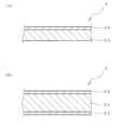
- FIG. 3 (A) shows the base material of the two-layer body in the separator of this invention
- FIG. 3 (B) shows the base material of a three-layer body.
- FIG. 3 (B) shows the base material of a three-layer body.
- the numerical range defined using the symbol “ ⁇ ” includes the numerical values at both ends (upper limit and lower limit) of “ ⁇ ”.
- “0.01 to 5” represents 0.01 or more and 5 or less.
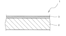
- FIG. 1 shows a schematic cross section of an example separator of the present invention.
- the dimensional ratio between the parts of the separator does not necessarily match the dimensional ratio between the parts of the actual separator.
- the separator of the present invention has a substrate 2 and a release layer 3 formed on at least one surface of the substrate 2 as shown in the separator 1 of the example.
- a strain generated in the separator when a load of 5 N / 20 mm is applied for 1 minute in the tensile direction of the separator (hereinafter, this strain may be abbreviated as “tensile strain”) is 7% or less. That is the first feature.
- the “tensile direction” is a direction parallel to a plane orthogonal to the thickness direction of the substrate 2.
- a roll that rolls the separator on the adhesive sheet by roll-to-roll.
- the expansion and contraction of the separator to be conveyed when obtaining the roll of the pressure-sensitive adhesive sheet) can be sufficiently suppressed, and the release layer can be prevented from being broken.
- the expansion / contraction of the separator conveyed when producing a separator roll can fully be suppressed, and destruction of a mold release layer can be prevented.
- the separator of the present invention preferably has a tensile strain of 5% or less, more preferably 4% or less.
- the strain when a load of 5 N / 20 mm is applied for 1 minute in the tensile direction of the separator is adopted because the tension applied to the separator in the production process of the pressure-sensitive adhesive sheet roll with separator and the production process of the separator roll and its This is because the time during which strain in tension is stabilized is taken into consideration.
- FIG. 2 shows a state in which the separator 1 shown in FIG. 1 is cut in the thickness direction of the substrate and divided into two parts (a state in which two separators are divided).
- the dimensional ratio between the parts of the separator does not necessarily match the dimensional ratio between the actual parts of the separator.
- the separator of the present invention has an apparent elastic modulus (E1) in the tensile direction of one separator divided body 1A when the substrate 1 is cut in half in the thickness direction and the separator 1 is divided into two.
- the second feature is that (E1> E2) which is larger than the apparent elastic modulus (E2) in the tensile direction of the other separator divided body 1B. That is, the elastic modulus in the tensile direction is different between one side and the other side (one surface side and the other surface side) of the separator in the thickness direction.
- the base material is cut in half in the thickness direction and the separator is divided into two” means that the base material 2 becomes two films 2 a and 2 b having a thickness approximately half the thickness of the base material 2.
- the separator 1 is divided into two parts.
- the two films having a thickness approximately half of the thickness of the base material 2 are such that when the thickness of the base material 2 is T, one film and the other film are each in the entire film thickness. Is within the range of (T / 2-0.1T) to (T / 2 + 0.1T).
- the “stretching direction of the separator divided body” is a direction parallel to a plane orthogonal to the thickness direction of the films 2 a and 2 b obtained by cutting the substrate 2.
- one separator divided body 1A has the release layer 3, and the other separator divided body 1B does not have the release layer 3.
- the presence or absence of the release layer in the separator divided body is not related to the magnitude relationship between the elastic moduli of the two separator divided bodies. That is, in two separator divided bodies, even if the apparent elastic modulus of the separator divided body having no release layer is larger than the apparent elastic modulus of the separator divided body having the release layer, the separator divided body having no release layer.
- the apparent elastic modulus may be smaller than the apparent elastic modulus of the separator divided body having the release layer. This is because the release layer does not substantially affect the elastic modulus in the tensile direction of the separator in the first place.
- the separator according to the present invention has such a second feature, so that it is difficult to generate wrinkles.
- the second feature is that the elastic modulus against the tension of the separator on one side and the other side in the thickness direction of the separator is different, and the elasticity on one side and the other side in the thickness direction is different. It is assumed that the difference in the rate eases the difference in tension between the inner and outer circumferences acting on the separator wound up to become a roll (winding body), and as a result, the generation of wrinkles is suppressed.
- the apparent elastic modulus (E1) in the tensile direction of one separator segment 1A is equal to the apparent elastic modulus (E2) in the tensile direction of the other separator segment 1B.
- 1.4 times or more (E1 ⁇ 1.4 ⁇ E2), preferably 2.5 times or more (E1 ⁇ 2.5 ⁇ E2), more preferably 2.8 times (E1 ⁇ 2. 8 ⁇ E2) is particularly preferred.
- the elastic modulus (E1) is preferably 1000 times or less (E1 ⁇ 1000 ⁇ E2), more preferably 200 times or less (E1 ⁇ 200 ⁇ E2), and 50 times the elastic modulus (E1) because there is a risk of rewinding by force.
- E1 ⁇ 50 ⁇ E2) is more preferable, 15 times or less (E1 ⁇ 15 ⁇ E2) is further more preferable, and 10 times or less (E1 ⁇ 10 ⁇ E2) is particularly preferable.
- the apparent elastic modulus (E2) in the tensile direction of the separator divided body having a lower apparent elastic modulus in the tensile direction is from the viewpoint of ensuring the strength that the separator is not broken when the separator is peeled from the adhesive sheet.
- 0.5 MPa or more is preferable, and 1 MPa or more is more preferable.
- the separator of the present invention can be used as a separator for protecting the pressure-sensitive adhesive layer of various pressure-sensitive adhesive sheets.
- a preferable specific example of the pressure-sensitive adhesive sheet to which the separator of the present invention is applied is a pressure-sensitive adhesive sheet having a position adjusting function. It is done. Here, an adhesive sheet having a position adjusting function will be described.
- FIG. 5 is a schematic perspective view of an adhesive sheet having a position adjusting function.
- the pressure-sensitive adhesive sheet 10 having a position adjusting function includes a pressure-sensitive adhesive layer 21 and a low-adhesive convex portion 22 partially provided on the surface of the pressure-sensitive adhesive layer 21.
- Reference numeral 23 in the figure is a support.
- “low adhesiveness” in the “low-adhesive convex portion” means non-adhesive (no tack), or the convex portion 22 has a lower tack than the adhesive layer 21.
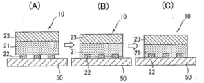
- FIG. 6 is a schematic cross-sectional view of the pressure-sensitive adhesive sheet and the adherend for explaining a change in state when the pressure-sensitive adhesive sheet 10 of FIG.
- the pressure-sensitive adhesive sheet having the position adjusting function has a low-adhesive convex portion 22 (hereinafter, “low-adhesive convex portion” is also simply referred to as “convex portion”) partially on the surface of the pressure-sensitive adhesive layer 21. Since the pressure-sensitive adhesive sheet 10 is placed on the surface of the adherend 50 (non-pressurized state), the low-adhesive convex portion 22 is formed as shown in FIG. Since the adhesive layer 21 is in contact with the adherend 50 and does not substantially contact the adherend 50, the adhesive sheet 10 can be easily moved on the surface of the adherend 50.
- FIG. 6C shows a state in which the pressure-sensitive adhesive sheet 10 is adhered to the adherend 50 by applying sufficient pressure to the pressure-sensitive adhesive sheet 10 placed on the surface of the adherend 50. As shown in FIG.
- the pressure-sensitive adhesive sheet 10 is attached to the adherend because the low-adhesive convex portion 22 is entirely embedded in the pressure-sensitive adhesive layer 21 by sufficient pressure applied to the pressure-sensitive adhesive sheet 10. 50 is bonded with a sufficient adhesive force.
- the pressure-sensitive adhesive sheet 10 having the position adjustment function can be easily adjusted on the adherend 50 until the position of adhesion to the adherend 50 is finally determined. Can be adhered to the adherend with sufficient adhesive force.
- the base material 2 in the separator 1 of the present invention is selected from resin (natural resin, synthetic resin), rubber, paper, metal, or a group consisting of the pressure-sensitive adhesive sheet to which the separator is applied, the shape of the pressure-sensitive adhesive layer, and the like. Various materials such as two or more kinds of composite materials can be applied. Moreover, it is preferable that the separator 1 of this invention comprises at least one part of the base material 2 with a porous film from a viewpoint of providing cushioning property to a separator. Moreover, although the base material 2 may be a single layer body or a multilayer body, a multilayer body is preferable from the ease of preparation of the separator which has the said 2nd characteristic.
- the substrate 2 is a multilayer body
- a two-layer body in which the thin layer 2B is provided on one side of the main layer 2A, or a three layer in which the thin layer 2B is provided on both sides of the main layer 2A.
- the body (FIG. 3B) is preferable, and a two-layer body is more preferable.
- the main layer 2A is preferably composed of a porous film.
- a separator having the second feature can be easily obtained by making the constituent materials, thicknesses, and the like of the two thin layers 2B provided on both surfaces of the main layer 2A different from each other.
- polyester for example, polyethylene terephthalate (PET), etc.), nylon, saran (trade name), polyvinyl chloride, polyethylene, polypropylene, ethylene-vinyl acetate copolymer
- polyolefin foam for example, , Non-crosslinked polyethylene foams, crosslinked polyethylene foams, polypropylene foams, foams composed of polyethylene (PE) and polypropylene (PP), etc.
- polyester foams for example, polyethylene terephthalate foams, etc.
- urethane foams for example, flexible urethane foam, hard (3) ethylene / propylene / diene rubber (EPDM), ethylene / propylene rubber, ethylene / propylene terpolymer, silicone rubber, etc.
- Fluorine rubber acrylic rubber, polyurethane rubber, polyamide rubber, natural rubber, chloroprene rubber, butyl rubber, nitrile butyl rubber, styrene / butadiene rubber, styrene / butadiene / styrene rubber, styrene / isoprene / styrene rubber, styrene / ethylene /
- One or more rubbers selected from the group consisting of butadiene rubber, styrene / ethylene / butylene / styrene rubber, and styrene / isoprene / propylene / styrene rubber are added as rubber components.
- Rubber foamed film rubber such as foam films; and the like.
- (4) paper, woven fabric, nonwoven fabric (for example, polyester (for example, polyethylene terephthalate (PET)) nonwoven fabric, etc.) and the like are also included in the porous film.
- the rubber-based foam film includes, for example, a rubber, a vulcanizing agent, an azodicarbonamide, a urea-based foaming aid, and a kinematic viscosity at 40 ° C. described in JP-A-2001-139715.
- an acrylic polymer such as poly (meth) acrylic acid alkyl ester, polyvinyl chloride, polyethylene, polypropylene, ethylene / vinyl acetate copolymer, poly Vinyl acetate, polyamide, polyester, chlorinated polyethylene, urethane polymer, styrene polymer, silicone polymer
- rubber foam film is vulcanized foam molded body of non-rubber-based polymer mixture further blended such as an epoxy resin.
- the thin layer 2B is made of polyester (for example, polyethylene terephthalate (PET), polyethylene naphthalate (PEN), etc.); polyamide (for example, nylon) Polyvinyl chloride (PVC); Polyvinyl acetate (PVAc); Polyvinylidene chloride; Polyolefin (eg, polyethylene (high density polyethylene, low density polyethylene), polypropylene, reactor TPO, ethylene / propylene copolymer, ethylene- Vinyl acetate copolymer (EVA), etc.); polyimide (PI); fluorine resin (For example, polytetrafluoroethylene); cellophane and ionomer resin (for example, resin selected from the group consisting of a polymer
- the solid film is preferably a polyolefin solid film, more preferably a high density polyethylene solid film or a low density polyethylene solid film.
- a skin layer can be applied to the thin layer 2B instead of the solid film.
- the skin layer is a resin foam film or rubber foam formed on the surface of the resin foam film of (2) above or (3) rubber foam film which is a porous film constituting the main layer 2A.
- This is a thin layer obtained by processing a predetermined thickness portion on the surface of the body film into an opening ratio smaller than the opening ratio of the film other than the predetermined thickness portion.
- the “perforation ratio” is the area ratio of micropores in the area of the thin layer on the plane perpendicular to the thickness direction of the resin foam film or rubber foam film.
- the porosity of the skin layer is preferably 10% or less, more preferably 5% or less, from the viewpoint of maintaining the cushioning property of the resin foam film or rubber foam film.
- the skin layer is usually formed by melting a predetermined thickness portion on the surface of a resin foam film or a rubber foam film. For example, by using a heating roll set at a temperature lower by about 5 to 20 ° C. than the melting point of the film and reducing the rotation speed of the heating roll from the running speed of the film, a skin layer is formed on the contact surface side of the heating roll of the film. Can be formed.
- the thickness of the main layer 2A is preferably 100 ⁇ m or more, more preferably 200 ⁇ m or more, and even more preferably 500 ⁇ m or more. Moreover, 5000 micrometers or less are preferable, 1500 micrometers or less are more preferable, and 1000 micrometers or less are still more preferable. Further, the thickness of the thin layer 2B is preferably 200 ⁇ m or less, more preferably 80 ⁇ m or less, and even more preferably 20 ⁇ m or less. Moreover, 1 micrometer or more is preferable, 3 micrometers or more are more preferable, and 5 micrometers or more are still more preferable.
- the compression elastic modulus of the separator is 1 MPa or less.
- the compression elastic modulus of the separator 1 covering the surface of the pressure-sensitive adhesive layer 21 of the pressure-sensitive adhesive sheet 10 having a position adjusting function is 1 MPa or less, the separator 1 is wound together with the pressure-sensitive adhesive sheet 10 into a roll and stored. Even when pressure due to tightening is applied to the pressure-sensitive adhesive sheet 10, as shown in FIG. 4, stress concentration on the low-adhesive convex portion 22 provided on the surface of the pressure-sensitive adhesive layer 21 is relieved by the separator 1.
- the compression elastic modulus of the separator 1 is more preferably 0.7 MPa or less, and particularly preferably 0.5 MPa or less.
- the pressure-sensitive adhesive sheet 10 having a position adjusting function the pressure-sensitive adhesive sheet is temporarily fixed to the adherend, or the pressure-sensitive adhesive sheet is bonded to the adherend by pressing the pressure-sensitive adhesive sheet (main bonding).
- the protrusion height of the low-adhesive convex portion 22 is preferably 200 ⁇ m or less. Therefore, when the separator 1 of the present invention is used as a separator for an adhesive sheet having a position adjusting function.
- the compression modulus is 1 MPa or less
- the compression stress at the time of 200 ⁇ m compression is 0.1 MPa or less
- the compression stress at the deformation amount 200 ⁇ m at the time of compression recovery after compression is 0.05 MPa or less. More preferred.
- the compression amount when the compression amount of the separator 1 and the deformation amount at the time of compression recovery correspond to the maximum protrusion height (200 ⁇ m) in the preferable range of the protrusion height of the low-adhesive protrusion 22 is sufficiently small.
- the protrusion height of the low-adhesive convex portion 22 is 200 ⁇ m or less, the stress acting on the low-adhesive convex portion 22 is sufficiently relaxed by the pressure caused by the tightness of the adhesive sheet, and the convex portion 22 is crushed. This is because the embedding of the convex portion 22 into the pressure-sensitive adhesive layer 21 can be prevented at a higher level.
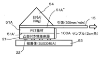
- the measurement of the compression elastic modulus of the separator, the compressive stress at the time of 200 ⁇ m compression, and the compressive stress at the deformation amount of 200 ⁇ m at the time of compression recovery is made by Shimadzu Corporation, a precision measuring device (autograph).
- the compression force measurement function can be used, and the temperature is 23 ° C., the indenter area is 1 cm 2 , the compression speed is 1 mm / min, and the center of the separator (4 cm ⁇ 4 cm) is perpendicular to the release treatment surface.
- the indenter is pressed to measure the compressive stress, and after reaching the target stress of 0.1 MPa, the cylindrical indenter is moved at a speed of 1 mm / min in the pulling direction to recover the compression.
- the porous film (resin foam film, rubber foam film, etc.) constituting the main layer 2A has an apparent density of 500 kg / m 3 or less measured in accordance with JIS K 7222 (2005). Is preferably 200 kg / m 3 or less, and more preferably 100 kg / m 3 or less.
- the porous film (resin foam film, rubber-based foam film, etc.) has such an apparent density, (a) a separator having a compression modulus of 1 MPa or less, (b) a compression modulus of 1 MPa or less, 200 ⁇ m A separator having a compressive stress of 0.1 MPa or less at the time of compression and a compressive stress of 0.05 MPa or less at a deformation amount of 200 ⁇ m upon compression recovery after compression of 200 ⁇ m is easily obtained.
- the apparent density of the porous film (resin foam film, rubber foam film, etc.) is a viewpoint of imparting elasticity to prevent the protrusions 22 from being crushed and the protrusions 22 from being embedded in the adhesive layer 21. Therefore, 1 kg / m 3 or more is preferable, and 10 kg / m 3 or more is more preferable.
- the porous film (resin foam film, rubber foam film, etc.) constituting the main layer 2A has an average major axis of fine pores in the range of 10 to 1000 ⁇ m and an average minor axis in the range of 10 to 1000 ⁇ m. Some are preferred.
- the porosity of a resin foam film, rubber foam film, etc. when the foam film is obtained by processing a predetermined thickness portion of its surface into a skin layer, The opening ratio of the portion other than the predetermined thickness portion (skin layer) on the surface of the foam film is preferably 50 to 99%, more preferably 60 to 98% from the viewpoint of the flexibility of the separator.
- the base material 2 is made of, for example, a resin foam film or a rubber-based material that becomes the main layer 2A by a conventional method for producing a laminated film, such as a hot press process using a hot press machine or a continuous heat laminate process using a roll-to-roll process. It is manufactured by laminating a solid film to be the thin layer 2B on one side or both sides of the foam film.
- the release layer 3 formed on at least one surface of the substrate 2 in the separator of the present invention is not particularly limited.
- a known release agent such as a fluorine release agent, a long-chain alkyl acrylate release agent, or a silicone release agent. It may be a release layer formed by an agent.
- a release layer formed of a silicone release agent is preferable, and a curing method such as ultraviolet irradiation or electron beam irradiation is preferably used as a release agent curing method.
- a curing method such as ultraviolet irradiation or electron beam irradiation is preferably used as a release agent curing method.
- cationically polymerizable UV-curable silicone-type release agents are preferable.
- Cationic polymerizable UV curable silicone release agent is a mixture containing cationic polymerization type silicone (polyorganosiloxane having epoxy functional group in the molecule) and onium salt photoinitiator, but onium salt photoinitiator It is particularly preferable that the agent is made of a boron photoinitiator, and it is particularly good when such an onium salt photoinitiator is a cationic polymerizable UV curable silicone release agent comprising a boron photoinitiator. Peelability (release property) is obtained.
- the cationic polymerization type silicone (polyorganosiloxane having an epoxy functional group in the molecule) has at least two epoxy functional groups in one molecule, and is linear or branched or A mixture thereof may be used.
- the type of epoxy functional group contained in the polyorganosiloxane is not particularly limited as long as ring-opening cationic polymerization proceeds with an onium salt photoinitiator. Specific examples include ⁇ -glycidyloxypropyl group, ⁇ - (3,4-epoxycyclohexyl) ethyl group, ⁇ - (4-methyl-3,4 epoxy cyclohexyl) propyl group and the like.
- Such cationic polymerization type silicone (polyorganosiloxane having an epoxy functional group in the molecule) is commercially available, and a commercially available product can be used.
- a commercially available product can be used.
- UV9315, UV9430, UV9300, TPR6500, TPR6501 manufactured by Toshiba Silicone Co., Ltd. X-62-7622, X-62-7629, X-62-7655, X-62-7660, X-62-7660 manufactured by Shin-Etsu Chemical Co., Ltd.
- Examples include 62-7634A, Poly200, Poly201, RCA200, RCA250, and RCA251 manufactured by Arakawa Chemical Co., Ltd.
- thermosetting addition type silicone release agent thermosetting addition type polysiloxane release agent
- the thermosetting addition-type silicone release agent essentially comprises a polyorganosiloxane containing an alkenyl group as a functional group in the molecule (alkenyl group-containing silicone) and a polyorganosiloxane containing a hydrosilyl group as a functional group in the molecule. Ingredients.
- the polyorganosiloxane having an alkenyl group as a functional group in the molecule a polyorganosiloxane having two or more alkenyl groups in the molecule is preferable.
- the alkenyl group include a vinyl group (ethenyl group), an allyl group (2-propenyl group), a butenyl group, a pentenyl group, and a hexenyl group.
- the alkenyl group is usually bonded to a silicon atom (for example, a terminal silicon atom or a silicon atom inside the main chain) of the polyorganosiloxane forming the main chain or skeleton.
- polyalkylalkylsiloxanes such as polydimethylsiloxane, polydiethylsiloxane, and polymethylethylsiloxane, and polyalkylarylsiloxanes.
- a copolymer for example, poly (dimethylsiloxane-diethylsiloxane), etc. in which a plurality of silicon atom-containing monomer components are used may be used. Of these, polydimethylsiloxane is preferred.
- polydimethylsiloxane having a vinyl group, hexenyl group or the like as a functional group is preferably exemplified.
- the polyorganosiloxane crosslinking agent containing a hydrosilyl group as a functional group in the molecule is a polyorgano having a hydrogen atom bonded to a silicon atom (particularly, a silicon atom having a Si—H bond) in the molecule.
- a siloxane, particularly a polyorganosiloxane having two or more silicon atoms having Si—H bonds in the molecule is preferred.
- the silicon atom having the Si—H bond may be either a silicon atom in the main chain or a silicon atom in the side chain, that is, may be contained as a constituent unit of the main chain, or It may be contained as a constituent unit of the side chain.
- the number of silicon atoms in the Si—H bond is not particularly limited as long as it is 2 or more.
- Specific examples of the polyorganosiloxane crosslinking agent containing a hydrosilyl group as a functional group in the molecule are polymethylhydrogensiloxane and poly (dimethylsiloxane-methylhydrogensiloxane).
- thermosetting silicone release agent a reaction inhibitor (reaction retarder) may be used together with the thermosetting silicone resin in order to impart storage stability at room temperature.
- reaction inhibitor for example, when a thermosetting addition-type silicone release agent is used as the release agent, specifically, for example, 3,5-dimethyl-1-hexyn-3-ol, 3 -Methyl-1-penten-3-ol, 3-methyl-3-penten-1-yne, 3,5-dimethyl-3-hexen-1-yne and the like.
- a release control agent or the like may be used as necessary for the thermosetting silicone release agent.
- a release control agent such as MQ resin, polyorganosiloxane having no alkenyl group or hydrosilyl group (trimethylsiloxy group end-blocked polydimethylsiloxane, etc.) and the like may be added.
- the content of these components in the release agent is not particularly limited, but is preferably 1 to 30% by weight based on the entire solid content.
- Thermosetting silicone release agent usually contains a curing catalyst.
- the curing catalyst is preferably a platinum-based catalyst that is generally used as a catalyst for thermosetting addition-type silicone. Among these, at least one platinum-based catalyst selected from chloroplatinic acid, platinum olefin complexes, and chloroplatinic acid olefin complexes is preferable.
- the curing catalyst can be used as it is or in a form dissolved or dispersed in a solvent.
- the blending amount (solid content) of the curing catalyst is preferably 0.05 to 0.55 parts by weight and preferably 0.06 to 0.50 parts by weight with respect to 100 parts by weight (resin content) of the thermosetting silicone resin. Further preferred. When the blending amount of the curing catalyst is less than 0.05 parts by weight, the curing rate is slow, and when it exceeds 0.55 parts by weight, the pot life is remarkably shortened.
- an organic solvent is usually used for the coating solution containing a release agent used when providing the release layer in order to improve the coating property.
- the organic solvent is not particularly limited, and examples thereof include aliphatic or alicyclic hydrocarbon solvents such as cyclohexane, hexane, and heptane; aromatic hydrocarbon solvents such as toluene and xylene; ethyl acetate, methyl acetate, and the like. Ester solvents; ketone solvents such as acetone and methyl ethyl ketone; alcohol solvents such as methanol, ethanol and butanol can be used. These organic solvents may be used alone or in combination of two or more.
- the thickness of the release layer 3 is preferably 0.001 to 10 ⁇ m, more preferably from the viewpoint of excellent peelability (release property) and suppression of thickness unevenness (stable formation of the release layer). Is 0.03 to 5 ⁇ m, particularly preferably 0.1 to 1 ⁇ m.
- the separator of the present invention is actually stored in a roll wound around a core core until it is used for protecting the adhesive layer of the adhesive sheet.
- This separator roll is usually manufactured roll-to-roll.
- a release layer is formed on at least one surface of the film by using a release agent while transporting a film fed from a roll of a film serving as a substrate (that is, coating and drying of a coating solution containing the release agent are performed).
- the film (separator) on which the release layer is formed is wound around the core core by a winding device to manufacture a separator roll.
- the outer diameter of the core is not particularly limited, but is generally about 1 to 3 inches.
- the winding tension of the separator is not particularly limited, but is generally about 30 to 200 N / 600 mm.
- the speed is not particularly limited, but is generally about 30 to 100 m / min.
- the pressure-sensitive adhesive layer 21 of the pressure-sensitive adhesive sheet 10 having a position adjusting function is a pressure-sensitive pressure-sensitive adhesive layer containing a pressure-sensitive pressure-sensitive adhesive as a main component.
- the pressure-sensitive adhesive (hereinafter also simply referred to as “adhesive”) is not particularly limited.
- a rubber-based adhesive an acrylic adhesive
- the pressure-sensitive adhesive include polyamide-based pressure-sensitive adhesives, silicone-based pressure-sensitive adhesives, polyester-based pressure-sensitive adhesives, ethylene-vinyl acetate copolymer-based pressure-sensitive adhesives, and urethane-based pressure-sensitive adhesives.
- the acrylic pressure-sensitive adhesive is excellent in various properties such as heat resistance and weather resistance, and it is possible to express desired properties by selecting the kind of monomer component constituting the acrylic polymer. Therefore, it can be preferably used.
- the acrylic pressure-sensitive adhesive is usually formed by a base polymer composed of (meth) acrylic acid alkyl ester as a main monomer component.
- the (meth) acrylic acid alkyl ester include, for example, methyl (meth) acrylate, ethyl (meth) acrylate, propyl (meth) acrylate, isopropyl (meth) acrylate, butyl (meth) acrylate, (meth) Isobutyl acrylate, s-butyl (meth) acrylate, t-butyl (meth) acrylate, pentyl (meth) acrylate, hexyl (meth) acrylate, heptyl (meth) acrylate, octyl (meth) acrylate, 2-Methylhexyl acrylate, isooctyl (meth) acrylate, nonyl (meth) acrylate, isononyl (meth
- the acrylic polymer contains units corresponding to other monomer components copolymerizable with the (meth) acrylic acid alkyl ester as necessary for the purpose of modifying cohesion, heat resistance, crosslinkability and the like. You may go out.
- monomer components include acrylic acid, methacrylic acid, carboxyethyl acrylate, carboxypentyl acrylate, itaconic acid, maleic acid, fumaric acid, crotonic acid and other carboxyl group-containing monomers; (meth) acrylic acid hydroxy Hydroxyl group-containing monomers such as butyl, hydroxyhexyl (meth) acrylate, hydroxyoctyl (meth) acrylate, hydroxydecyl (meth) acrylate, hydroxylauryl (meth) acrylate, (4-hydroxymethylcyclohexyl) methyl methacrylate; Styrene sulfonic acid, allyl sulfonic acid, 2- (meth) acrylamide-2-methylprop
- the acrylic copolymer can be produced by subjecting the above (meth) acrylic acid alkyl ester and, if necessary, other monomers to polymerization by a known appropriate method.
- the molecular weight and the like of the acrylic copolymer are not particularly limited, and for example, those having a weight average molecular weight of 100,000 to 2,000,000, preferably 150,000 to 1,000,000, more preferably 300,000 to 1,000,000 can be used.
- the pressure sensitive adhesive uses a polymer having an acidic group such as a carboxyl group as the base polymer, and a hydrophilicity imparted by adding a neutralizing agent to neutralize all or some of the acidic groups in the base polymer. It is good also as an adhesive.
- the hydrophilic adhesive generally has little adhesive residue on the adherend, and even when adhesive residue is generated, it can be easily removed by washing with pure water.
- the polymer having an acidic group is obtained by copolymerizing a monomer having an acidic group such as the above-mentioned carboxyl group-containing monomer when preparing the base polymer.
- neutralizing agent examples include primary amines such as monoethylamine and monoethanolamine, secondary amines such as diethylamine and diethanolamine, triethylamine, triethanolamine, N, N, N′-trimethylethylenediamine, N-methyldiethanolamine, Examples thereof include organic amino compounds exhibiting alkalinity, such as tertiary amines such as N, N-diethylhydroxylamine.
- the pressure-sensitive adhesive may contain a crosslinking agent as required.
- the crosslinking agent include an epoxy crosslinking agent, an isocyanate crosslinking agent, a melamine crosslinking agent, a peroxide crosslinking agent, a metal alkoxide crosslinking agent, a metal chelate crosslinking agent, a metal salt crosslinking agent, and a carbodiimide crosslinking.
- Crosslinkers such as an agent, an oxazoline crosslinker, an aziridine crosslinker, and an amine crosslinker can be used, and an epoxy crosslinker, an isocyanate crosslinker, and the like can be preferably used. You may use these individually or in combination of 2 or more types.
- epoxy crosslinking agent examples include N, N, N ′, N′-tetraglycidyl-m-xylenediamine, diglycidylaniline, 1,3-bis (N, N-glycidylaminomethyl) cyclohexane, 1,6 -Hexanediol diglycidyl ether, neopentyl glycol diglycidyl ether, ethylene glycol diglycidyl ether, propylene glycol diglycidyl ether, polyethylene glycol diglycidyl ether, polypropylene glycol diglycidyl ether, sorbitol polyglycidyl ether, glycerol polyglycidyl ether, pentaerythritol Polyglycidyl ether, polyglycerol polyglycidyl ether, sorbitan polyglycidyl ether, trimethylolpropane polyglycidyl ether Ter, adipic acid digly
- isocyanate-based crosslinking agent examples include lower aliphatic polyisocyanates such as 1,2-ethylene diisocyanate, 1,4-butylene diisocyanate, 1,6-hexamethylene diisocyanate; cyclopentylene diisocyanate, cyclohexylene diisocyanate, and isophorone diisocyanate.
- Aliphatic polyisocyanates such as hydrogenated tolylene diisocyanate and hydrogenated xylene diisocyanate; aromatics such as 2,4-tolylene diisocyanate, 2,6-tolylene diisocyanate, 4,4'-diphenylmethane diisocyanate, xylylene diisocyanate And polyisocyanates.
- the pressure-sensitive adhesive layer 21 may contain additives such as a plasticizer, a stabilizer, a filler lubricant, a colorant, an ultraviolet absorber, an antioxidant, and a colorant.
- the pressure-sensitive adhesive layer 21 preferably has an elastic modulus of 0.01 to 10 MPa, more preferably 0.1 to 10 MPa in order to exhibit sufficient tack.
- the pressure-sensitive adhesive sheet 10 having a position adjusting function is in a state in which the low-adhesive convex portion 22 is embedded in the pressure-sensitive adhesive layer 21 when pressed, and the pressure-sensitive adhesive layer 21 is attached to the adherend 50. It is the structure which contacts and expresses adhesive force. Therefore, the relationship between the elastic modulus of the pressure-sensitive adhesive layer 21 and the elastic modulus of the low-adhesive convex portion 22 becomes important. As will be described later, in order to exhibit the position adjusting function, the low-adhesive convex portion 22 needs not to be deformed itself in a contact state with the adherend, and for that reason, an elastic modulus of 0.1 MPa or more.
- the thickness of the pressure-sensitive adhesive layer 21 is not particularly limited, but is preferably 10 to 1000 ⁇ m, more preferably 50 to 500 ⁇ m, and particularly preferably 70 to 250 ⁇ m.
- the pressure-sensitive adhesive sheet can be adhered with sufficient adhesive force during pressure bonding of the pressure-sensitive adhesive sheet after position adjustment while maintaining the position adjustment function by the low-tackiness convex portion 22. The sheet can be adhered to the adherend.
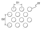
- the low-adhesive convex portions 22 are provided in the form of dots on the surface of the pressure-sensitive adhesive layer 21.
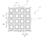
- 7 and 8 are plan views of the main parts of the pressure-sensitive adhesive sheet having the position adjusting function of other examples.
- the low-adhesive convex portions 22 are provided in a stripe shape and a lattice shape, respectively. ing.
- the low-adhesive convex portions 22 are only required to be provided in a uniform pattern on the entire surface of the pressure-sensitive adhesive layer 21, and the shape of the pattern is not particularly limited.
- a dot shape, a stripe shape, a lattice shape, a net shape or the like is preferable.
- “lattice” and “mesh” are “lattice” is a pattern of convex portions in which the planar shape of the hole (non-existing portion of the convex portion) is a square or a rectangle, Is different in that the planar shape of the hole (the non-existent portion of the convex portion) is a convex pattern that has a shape other than a square and a rectangle.
- the shape of the hole portion may be all the same or may be different for each hole portion, but it is preferable that they are all the same.
- each dot is a triangle, a quadrangle (for example, a square, a rectangle, a rhombus, a trapezoid, etc.), or a circle (for example, a perfect circle or a perfect circle) (Circle, ellipse shape, etc.), oval, regular polygon (square, etc.), star shape, etc., and the dot arrangement is not particularly limited, but is a square matrix, staggered, etc. Is preferred.
- the dots (projections 22) having a circular planar shape are arranged in a staggered manner.
- the planar area of the dot (projection 22) is preferably 0.007 ⁇ 20 mm 2, more preferably 0.2 ⁇ 1.8 mm 2.
- the plane area of the dots (convex portions 22) may be the same for all the dots (convex portions 22) or may be different for each dot (convex portion 22). 22) is preferably the same.
- the pitch (distance between the center points) between adjacent dots (convex portions 22) is preferably 0.1 to 5 mm, and more preferably 0.2 to 2 mm.
- each line portion is preferably 0.1 to 5 mm, and more preferably 0.2 to 2 mm. Further, the width (D in FIG. 7) of the space between adjacent line parts (convex parts) is preferably 0.1 to 5 mm, and more preferably 0.2 to 2 mm.
- the widths of the vertical and horizontal line portions (convex portions) are each preferably 0.1 to 5 mm, more preferably 0.2 to 2 mm. preferable.
- the pitch between adjacent line parts (convex parts) in the vertical and horizontal directions is preferably 0.1 to 5 mm, more preferably 0.2 to 2 mm. preferable.
- the planar area, width, and the like of the convex portion 22 are the area of the portion that becomes the maximum area of the convex portion 22 when the surface of the adhesive layer 21 is viewed from vertically above the surface of the adhesive layer 21, and the convex portion. This is the width of the portion having the maximum width of 22.
- the convex portion 22 may have a flat surface or a non-flat surface at the tip that contacts the adherend 50.
- the protrusion height of the low-adhesive convex portion 22 from the surface of the pressure-sensitive adhesive layer 21 is preferably 200 ⁇ m or less, more preferably 150 ⁇ m or less, and particularly preferably 130 ⁇ m or less. Moreover, Preferably it is 1 micrometer or more, More preferably, it is 10 micrometers or more. If the protrusion height exceeds 200 ⁇ m, the pressure-sensitive adhesive sheet may have insufficient adhesiveness or adhesive strength. If the protrusion height is less than 1 ⁇ m, the position adjustment function by the low-adhesive convex portion 22 is insufficient. There is a possibility.
- the protrusion height of the convex portion 22 is preferably 3 to 100%, more preferably 10 to 100% of the thickness of the pressure-sensitive adhesive layer 21 based on the thickness of the pressure-sensitive adhesive layer 21. is there. If the protruding height of the convex portion 22 is less than 3% of the protruding height of the pressure-sensitive adhesive layer 21, the position adjustment function of the pressure-sensitive adhesive sheet may be insufficient, and conversely the thickness of the convex portion is the pressure-sensitive adhesive. If it exceeds 100% of the thickness of the layer, the pressure-sensitive adhesive sheet may have insufficient tackiness and adhesive strength.
- the occupancy ratio of the low-adhesive convex portions 22 on the surface of the pressure-sensitive adhesive layer 21 ([total area of convex portions 22 / area of the entire surface of the pressure-sensitive adhesive layer] ⁇ 100 (%)) is low. From the viewpoint of friction (that is, easy mobility on the adherend), it is preferably 30 to 90%, more preferably 40 to 80%.
- the constituent material of the low-adhesive convex portion 22 can be selected according to the type of the adhesive that constitutes the adhesive layer 21. That is, any non-adhesive (having no tack) or lower tack than the pressure-sensitive adhesive layer 21, insoluble in the pressure-sensitive adhesive layer 21, and having shape retentivity should be used. Can do.
- inorganic materials such as glass powder, glass fiber, silica beads, aluminum oxide beads, metal fibers, metal nets, synthetic resin beads, synthetic resin balloons, natural fibers, synthetic resin fibers, natural resins and / or synthetics Organic materials such as resin moldings (threads, nets, lattices), or pressure-sensitive adhesives with lower tack than the adhesive layer 21 (for example, rubber-based, acrylic-based, ethylene-vinyl acetate copolymer systems, etc.) ) And the like.
- the constituent material of the low-adhesive convex part 22 can use 1 type (s) or 2 or more types.
- the constituent material of the low-adhesive convex portion 22 has a lower tack than the pressure-sensitive adhesive layer 21 is that the elastic modulus measured by the nano indenter by the constituent material of the low-adhesive convex portion 22 is the adhesive. It is larger than the elastic modulus of the layer 21.
- the elastic modulus is a composite elastic modulus obtained by a nanoindentation test using “TriboScope” manufactured by Nanoindenter Hysitron.
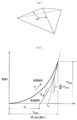
- the nanoindentation test is a process in which a Berkovich indenter (triangular pyramid diamond indenter) is gradually pushed into the subject until a predetermined maximum load Pmax is obtained by applying a load P (hereinafter referred to as a load process), and for a certain time at the maximum load Pmax.
- the indenter load P and the indentation depth h obtained in the holding process (hereinafter referred to as the holding process), and after the holding, in the process of gradually unloading and extracting until the load P becomes 0 (hereinafter referred to as the unloading process) From the relationship, this is a test to measure the elastic properties of the subject.
- the indentation depth h means the distance between the tip of the indenter and the surface of the test material in the initial state (the surface of the test material before the indenter is pushed in), and is based on the position where the indenter first contacts the surface of the test material. This corresponds to the displacement of the indenter.
- the elastic modulus of the convex portion 22 and the pressure-sensitive adhesive layer 21 is calculated by the following equation (1) based on the relationship between the indenter load P obtained by the nanoindentation test and the indentation depth h.
- Er 1 / ⁇ ⁇ S / 2 ⁇ ( ⁇ / A) 1/2 (1)
- ⁇ a constant determined by the shape of the indenter
- ⁇ 1.034 is used in the case of a Barkovic indenter.
- S represents the contact rigidity
- ⁇ represents the circumference
- A represents the contact projection area between the indenter and the surface of the test material.
- the elastic modulus of the pressure-sensitive adhesive layer is measured by bringing the indenter into contact with the surface of the pressure-sensitive adhesive layer of the test material (pressure-sensitive adhesive sheet).
- the elastic modulus of the convex portion is obtained by removing only the convex portion on the pressure-sensitive adhesive sheet from the pressure-sensitive adhesive layer under an environment of ⁇ 100 ° C. or less using an ultramicrotome with a diamond blade attached. It is measured by cutting out, fixing to a predetermined sample stage (made of SUS), and bringing an indenter into contact with the surface of the convex portion.
- the contact rigidity S is calculated based on the relationship obtained in the unloading process among the relationship between the indenter load P and the indentation depth h obtained by the nanoindentation test. More specifically, the contact rigidity S is determined by the unloading process after the holding process after the indenter position reaches the maximum pressing depth hmax (the pressing depth when the maximum load Pmax is applied). It is defined by the slope of the unloading curve immediately after transition to. In other words, the contact rigidity S means the gradient (dP / dh) of the tangent line L to the unloading curve at the point (hmax, Pmax).
- measurement and analysis of elastic modulus use measurement / analysis software TriboScan Ver.8.0.0.4 manufactured by Hysitron.
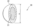
- FIG. 11 shows a schematic side view of the convex portion 22 made of an aggregate of a plurality of coherent particles 30.
- the aggregate (convex portion 22) of the plurality of coherent particles 30 is a flat body having a curved upper surface and a circular plan view.
- the aggregating particle means a particle having a predetermined cohesive force, and can be grasped as an aggregate of particles.
- Examples of the plurality of cohesive particles 30 include a polymer particle group derived from a polymer emulsion, and the polymer particle group derived from the polymer emulsion includes a polymer particle group composed of particles having a single polymer composition, and / or And a polymer particle group composed of core-shell structure polymer particles having different polymer compositions in the core and the shell.
- particles having a single polymer composition are also referred to as “non-core-shell structured polymer particles”.
- an additive is not always necessary, but, for example, an epoxy-based cross-linking agent or a silane is added to the polymer emulsion as long as it does not affect the performance of the convex portion 22.
- An additive such as a coupling agent may be added to increase the cohesive force of the polymer particle group.
- the polymer emulsion that is the source of the polymer particles is obtained by emulsion polymerization, that is, by polymerizing the monomer emulsion.
- the monomer component in the polymer emulsion (that is, the monomer constituting the monomer emulsion) preferably contains an alkyl acrylate ester and / or an alkyl alkyl methacrylate.
- alkyl acrylates examples include ethyl acrylate, propyl acrylate, n-butyl acrylate, t-butyl acrylate, n-hexyl acrylate, cyclohexyl acrylate, 2-ethylhexyl acrylate, n-octyl acrylate, and One or more kinds selected from lauryl acrylate are preferable.
- alkyl methacrylate include methyl methacrylate, ethyl methacrylate, propyl methacrylate, n-butyl methacrylate, t-butyl methacrylate, n-methacrylate.
- One or more selected from hexyl, cyclohexyl methacrylate, 2-ethylhexyl methacrylate, n-octyl methacrylate, lauryl methacrylate, and isobornyl methacrylate are preferred.
- carboxyl group-containing monomers such as acrylic acid, methacrylic acid, carboxyethyl acrylate, carboxypentyl acrylate, itaconic acid, maleic acid, fumaric acid, and crotonic acid, hydroxybutyl (meth) acrylate, and hydroxyhexyl (meth) acrylate Hydroxyl group-containing monomers such as hydroxyoctyl (meth) acrylate, hydroxydecyl (meth) acrylate, hydroxylauryl (meth) acrylate, and (4-hydroxymethylcyclohexyl) methyl methacrylate can be contained.
- One or more carboxyl group-containing monomers and hydroxyl group-containing monomers can be used.
- the core-shell structured polymer particle group is preferably composed of core-shell structured polymer particles having a shell elastic modulus higher than the core elastic modulus, and the core weight relative to the shell weight is 80% or less (preferably 80% or less, 10% % Or more) is preferably composed of core-shell structure polymer particles having a core-shell structure.
- the low-adhesive convex portion 22 is constituted by the polymer particle group including the core-shell structure polymer particles in which the elastic modulus of the shell is set higher than the elastic modulus of the core. It becomes frictional and the position adjustment function by the low-adhesive convex part 22 is improved, and an appropriate elastic modulus can be obtained in relation to the pressure-sensitive adhesive layer 21.
- FIG. 12 is a cross-sectional perspective view of the core-shell structure polymer particles 30 constituting the core-shell structure polymer particle group.
- Each core-shell structure polymer particle 30 has an acrylic polymer (A1) in which the core 31 has an alkyl acrylate as a main monomer component. It is preferable that the shell 32 is made of an acrylic polymer (A2) having an acrylic acid alkyl ester and a methacrylic acid alkyl ester as main monomer components.
- the core-shell structure polymer particles 30 constituting the core-shell structure polymer particle group have a substantially spherical shape, and the average particle diameter “a” is appropriately changed in consideration of the maximum diameter “A” and the height “B” of the convex portion 22. (See FIG. 11).
- the particle diameter of the core-shell structure polymer particle 30 in consideration of the maximum diameter “A” and the height “B” of the convex portion 22 is preferably 100 nm or more from the viewpoint of the viscosity of the aqueous dispersion (polymer emulsion).
- the viewpoint of the cohesiveness of the particles after drying that is, after removing water from the aqueous dispersion (polymer emulsion)
- it is preferably 300 nm or less, more preferably 200 nm or less.
- the maximum diameter “A” of the convex portion 22 in this case is preferably 100 ⁇ m or more, more preferably 250 ⁇ m or more from the viewpoint of the shape stability of the convex portion, and preferably from the viewpoint of the adhesive strength of the pressure-sensitive adhesive sheet. 3 mm or less, more preferably 2 mm or less, and the height “B” is preferably 1 ⁇ m or more, more preferably 10 ⁇ m or more from the viewpoint of stability of the position adjustment function, and from the viewpoint of adhesive force, preferably 100 ⁇ m. Below, more preferably 80 ⁇ m or less.
- BA butyl acrylate
- BA alkyl acrylate
- BA alkyl methacrylic acid ester
- alkyl acrylates other than butyl acrylate (BA), ethyl acrylate, propyl acrylate, t-butyl acrylate, n-hexyl acrylate, cyclohexyl acrylate, 2-ethylhexyl acrylate, acrylic acid are preferable.
- examples thereof include n-octyl and lauryl acrylate, and the alkyl acrylate can be used alone or in combination of two or more.
- alkyl acrylates having 3 to 9 carbon atoms in the alkyl group such as propyl acrylate, 2-ethylhexyl acrylate and n-octyl acrylate, are preferred.
- the alkyl methacrylate is a component that is copolymerized mainly for the purpose of controlling the elastic modulus of the polymer.
- the alkyl methacrylate has 1 to 18 carbon atoms in the alkyl group (for example, methyl methacrylate).
- methyl methacrylate, ethyl methacrylate, cyclohexyl methacrylate and the like are preferable.
- the alkyl methacrylates can be used alone or in combination of two or more.
- the acrylic polymer (A1) preferably contains 60 to 100% by weight of the acrylic acid alkyl ester, more preferably 70 to 99.9% by weight, and more preferably 80 to 99% by weight in all monomer components. The content is more preferably 80 to 98% by weight.
- the acrylic polymer (A1) may be copolymerized with a carboxyl group-containing monomer or a hydroxyl group-containing monomer in order to improve the adhesiveness of the pressure-sensitive adhesive and impart stability to the emulsion.
- carboxyl group-containing monomer include acrylic acid, methacrylic acid, carboxyethyl acrylate, carboxypentyl acrylate, itaconic acid, maleic acid, fumaric acid, and crotonic acid.
- the hydroxyl group-containing monomers include hydroxybutyl (meth) acrylate, hydroxyhexyl (meth) acrylate, hydroxyoctyl (meth) acrylate, hydroxydecyl (meth) acrylate, hydroxylauryl (meth) acrylate, ( 4-hydroxymethylcyclohexyl) methyl methacrylate and the like.
- the carboxyl group-containing monomer and / or hydroxyl group-containing monomer is preferably contained in an amount of 0.1 to 8% by weight, more preferably 1 to 7% by weight, based on all monomer components constituting the acrylic polymer (A1).
- the content is preferably 2 to 5% by weight, and more preferably.
- the acrylic polymer (A2) mainly composed of an acrylic acid alkyl ester and a methacrylic acid alkyl ester constituting the shell preferably contains 30 to 95% by weight of the methacrylic acid alkyl ester in all the monomer components.
- the content is more preferably 90% by weight, particularly preferably 40 to 80% by weight.
- the alkyl methacrylate is an alkyl methacrylate having an alkyl group having 1 to 18 carbon atoms (for example, methyl methacrylate (MMA), ethyl methacrylate, propyl methacrylate, n-butyl methacrylate, t-butyl methacrylate, N-hexyl methacrylate, cyclohexyl methacrylate, 2-ethylhexyl methacrylate, n-octyl methacrylate, lauryl methacrylate, isobornyl methacrylate, etc.) are used.
- MMA methyl methacrylate
- ethyl methacrylate propyl methacrylate
- n-butyl methacrylate t-butyl methacrylate
- N-hexyl methacrylate cyclohexyl methacrylate
- 2-ethylhexyl methacrylate 2-ethylhexy
- methyl methacrylate (MMA), ethyl methacrylate, t-butyl methacrylate, isobornyl methacrylate and the like are preferable, and methyl methacrylate (MMA) is particularly preferable.
- the acrylic acid alkyl ester is a component that is copolymerized mainly for the purpose of controlling the elastic modulus of the polymer.
- the acrylic acid alkyl ester having an alkyl group having 1 to 18 carbon atoms is used.
- the acrylic acid alkyl ester can be used alone or in combination of two or more.
- alkyl acrylates having 3 to 9 carbon atoms such as propyl acrylate, butyl acrylate (BA), 2-ethylhexyl acrylate, and n-octyl acrylate are preferred, and butyl acrylate (BA Is particularly preferred.
- the acrylic polymer (A2) may be copolymerized with a carboxyl group-containing monomer or a hydroxyl group-containing monomer in order to improve the adhesiveness of the pressure-sensitive adhesive and to impart stability to the emulsion.
- carboxyl group-containing monomer include acrylic acid, methacrylic acid, carboxyethyl acrylate, carboxypentyl acrylate, itaconic acid, maleic acid, fumaric acid, and crotonic acid.
- the hydroxyl group-containing monomers include hydroxybutyl (meth) acrylate, hydroxyhexyl (meth) acrylate, hydroxyoctyl (meth) acrylate, hydroxydecyl (meth) acrylate, hydroxylauryl (meth) acrylate, ( 4-hydroxymethylcyclohexyl) methyl methacrylate and the like.
- the carboxyl group-containing monomer and / or the hydroxyl group-containing monomer is preferably contained in an amount of 0.1 to 8% by weight, preferably 1 to 7% by weight, based on all monomer components constituting the acrylic polymer (A2). More preferably, the content is 2 to 5% by weight.
- the acrylic polymer (A2) preferably contains butyl acrylate (BA) and methyl methacrylate (MMA) as monomer components.
- the acrylic polymer (A2) contains methacrylic methacrylate (BA) based on the weight (M) of butyl acrylate (BA) in the acrylic polymer (A2).
- the “MMA ratio (%)”, which is the ratio (N / M) of the weight (N) of methyl acid (MMA), should be changed according to the adherend to which the adhesive sheet is to be attached, the constituent material of the adhesive layer 21 and the like. However, 100% or less is preferable, and 40 to 80% is more preferable.
- the “core-shell ratio (%)” which is the ratio (L / K) of the weight (L) of the core 31 to the weight (K) of the shell 32, is preferably 100% or less, and 20 to 80% Is more preferable.
- the weight ratio of the shell 32 to the core 31 in the core-shell structure polymer particles and details of the core-shell structure can be analyzed by, for example, DSC measurement or TEM (3D-TEM) method.
- the polymer emulsion that is the source of the polymer particle group consisting of the core-shell structure polymer particles and the polymer particle group consisting of the non-core shell structure polymer particles can be obtained by emulsion polymerization, that is, polymerizing the monomer emulsion.
- Emulsion polymerization for obtaining a polymer emulsion that is a source of polymer particles composed of non-core-shell structure polymer particles can be performed by a conventional method. That is, an emulsifier (surfactant), a radical polymerization initiator, a chain transfer agent and the like are appropriately blended with the above-mentioned monomers, for example, a batch charging method (batch polymerization method), a monomer dropping method, a monomer emulsion dropping, for example.
- the emulsion polymerization is carried out by a known emulsion polymerization method such as a method. In the monomer dropping method, continuous dropping or divided dropping is appropriately selected.
- Known emulsion polymerization methods can be combined as appropriate.
- the reaction conditions and the like are appropriately selected, but the polymerization temperature is preferably about 40 to 95 ° C., for example, and the polymerization time is preferably about 30 minutes to 24 hours.
- the emulsion polymerization for obtaining a polymer emulsion that is a source of the polymer particle group composed of the core-shell structure polymer particles is an emulsion polymerization for generating a polymer that becomes a core of the core-shell structure polymer particles, and becomes a generated core.
- multi-stage emulsion polymerization is performed in which emulsion polymerization for producing a polymer to be a shell is performed.
- Each emulsion polymerization can be carried out by a conventional method, and may be carried out according to the above-mentioned methods and conditions.
- agglomerated particles polymer particle group consisting of core-shell structure polymer particles having a core-shell ratio of 50% and an MMA ratio of 50% is shown below.
- Latemul E-118B manufactured by Kao Corporation
- BA butyl acrylate
- a mixture of 205 parts by weight of ion-exchanged water was prepared, and a monomer emulsion A was prepared by stirring at 6000 rpm for 5 minutes in a nitrogen atmosphere using a homomixer (manufactured by Tokushu Kika Kogyo Co., Ltd.).
- MMA methyl methacrylate
- BA butyl acrylate
- the monomer emulsion B was added dropwise over 2.5 hours while adding 0.5 parts by weight of V-50 to 50 parts by weight of butyl acrylate (BA) and keeping the temperature at 60 ° C. And an aqueous dispersion containing core-shell structure polymer particles having a solid content concentration of 40% was obtained.
- the average particle diameter of the obtained core-shell structure polymer particles was 160 nm.
- a polymer emulsion (emulsion liquid) using a general printing technique such as a method of transferring a polymer emulsion (emulsion liquid) to the surface of the pressure-sensitive adhesive layer 21 with a gravure roll engraved with a mark, screen printing, offset printing, flexographic printing, etc.
- the method etc. of printing are mentioned.
- Individual particles in the plurality of cohesive particles are substantially spherical before becoming an aggregate of particles.
- the average particle size of the plurality of aggregating particles is preferably 100 nm or more, more preferably 120 nm or more.
- the polymer emulsion (aqueous dispersion) is dried. From the viewpoint of the cohesiveness of the later polymer particles, it is preferably 300 nm or less, more preferably 200 nm or less.
- the maximum diameter of the convex portion 22 formed by the plurality of coherent particles 30 is preferably 100 nm or more, more preferably 250 nm or more.
- the thickness is preferably 3 mm or less, more preferably 2 mm or less.
- the height of the convex portion 22 is preferably 1 ⁇ m or more, more preferably 10 ⁇ m or more. From the viewpoint of adhesive strength, it is preferably 200 ⁇ m or less, more preferably 100 ⁇ m or less, and particularly preferably 80 ⁇ m or less.
- the average particle size of the plurality of cohesive particles is measured by the following method.
- the diameter of each aggregating particle is measured by a laser diffraction scattering method for several aggregating particles randomly extracted from a plurality of aggregating particles forming a certain convex portion 22, and several measured agglomerated particles are measured.
- the process of adopting the value located in the center of the diameter of the coherent particles is one cycle, and several median diameters obtained by repeating this cycle several times
- the average value is defined as the average particle size.
- the low-adhesive convex portion 22 is a convex portion made of a porous screen.
- the porous screen refers to a porous (or perforated) sheet-like material.
- the porous screen includes a net-like material.
- porous screen examples are not particularly limited, and examples thereof include a plastic net, a fiber net, and a metal thread net.
- a plastic sheet, a thin metal sheet, a woven fabric, a non-woven fabric, a paper or the like that has been subjected to perforation treatment can be used.
- the shape of the hole or mesh of the porous screen is not particularly limited as long as the above characteristics can be exhibited.
- the shape is triangular, quadrangular (for example, square, rectangular, rhombus, trapezoid, etc.), circular (for example, perfect circle, perfect circle) Near a circle, an elliptical shape, etc.).
- the indefinite shape similar to the said shape may be sufficient.
- all the holes or mesh shapes may be the same, or may be different for each hole.
- the thickness of the porous screen is not particularly limited as long as it exhibits the above characteristics, but is preferably 10 to 200 ⁇ m, and more preferably 50 to 150 ⁇ m, for example. If the thickness is less than 10 ⁇ m, the slipperiness may be deteriorated. On the other hand, if the thickness exceeds 200 ⁇ m, the adhesiveness and the slipperiness may not be compatible.
- the material is not particularly limited, and examples thereof include synthetic resins (plastics) such as nylon, polyethylene, polypropylene, and polyester, natural fibers, and metal fibers.
- synthetic resins such as nylon, polyethylene, polypropylene, and polyester, natural fibers, and metal fibers.
- the basis weight is not particularly limited, but is preferably 1.0 to 70 g / m 2 , more preferably 2.0 from the viewpoint of achieving both adhesiveness and slipperiness on the adhesive surface to which the porous screen is bonded. ⁇ 20 g / m 2 .
- the size of the mesh is not particularly limited, but is preferably 5 pieces / inch to 50 pieces / inch, more preferably 20 pieces, from the viewpoint of achieving both adhesion and slipperiness on the adhesive surface on which the porous screen is bonded. / Inch to 40 pieces / inch.
- net commercial products examples include trade name “Net ND20” manufactured by Daisen Corporation.
- the material is not particularly limited, but plastic and non-woven fabric are preferable from the viewpoint of compatibility between adhesiveness and slipperiness on the adhesive surface on which the porous screen is bonded.
- the pore size of the porous screen is not particularly limited as long as the above characteristics can be exhibited, and the pore size may be common or may be different for each hole.
- the size of such a hole is, for example, about 500 ⁇ m to 10 mm at the largest part of the hole.
- the distribution of pores in the porous screen is not particularly limited as long as the above characteristics can be exhibited, and may be concentrated in a certain region or may be dispersed as a whole.
- the distance between the holes of the porous screen is not particularly limited, and may be constant or may not be constant.
- a convex portion made of solid particles can be mentioned.
- solid particles include calcium carbonate, barium carbonate, calcium sulfate, aluminum sulfate, molybdenum disulfide, titanium oxide, alumina, silica, magnesium oxide, calcium oxide, calcium hydroxide, ferrous oxide, ferric oxide.
- Inorganic solid particles such as glass beads; cured rubber, ebonite, lignin / phenol resin, styrene resin, vinyl chloride resin, (meth) acrylic resin, polypropylene resin, polyethylene resin, melamine resin, urea resin, other resins, etc.
- Organic solid particles can be mentioned.
- One kind or two or more kinds of solid particles can be used.
- hollow solid particles can be used as long as the hollow particle walls are not crushed by the pressure applied by pressure.
- hollow solid particles include urea resin balloons, melamine resin balloons, phenol resin balloons, polyvinylidene chloride balloons, organic balloons such as epoxy resin balloons; glass balloons, shirasu balloons, carbon balloons, alumina balloons, Examples thereof include hollow solid particles in which the hollow particle walls are not crushed by pressure bonding pressure such as an inorganic balloon such as a silica sand balloon.
- the term “not crushed” is used in a sense that even a part of the hollow particle wall is broken and the gas in the hollow particles does not leak to the outside.
- the solid particles preferably have an average particle diameter of 1 to 100 ⁇ m.
- the average particle diameter of the solid particles can be measured by a laser diffraction / scattering method.
- the particle size distribution of the inorganic filler can be created on a volume basis with a laser diffraction / scattering particle size distribution measuring apparatus, and the median diameter can be measured as the average particle diameter.
- the measurement sample one obtained by dispersing solid particles in water by ultrasonic waves can be preferably used.
- the surface opposite to the surface provided with the low-adhesive convex portion 22 of the pressure-sensitive adhesive layer 21. has a support 23.
- the support 23 is not particularly limited. Specifically, the support 23 is polyester (for example, polyethylene terephthalate (PET)), nylon, saran (trade name), polyvinyl chloride, polyethylene, polypropylene, and ethylene-vinyl acetate. Examples thereof include a single film such as a polymer, polytetrafluoroethylene, and ionomer resin, a metal foil, or a laminate film obtained by laminating two or more films selected from these.
- PET polyethylene terephthalate
- nylon nylon
- saran trade name
- polyvinyl chloride polyethylene
- polypropylene polypropylene
- ethylene-vinyl acetate examples thereof include a single film such as a polymer, polytetrafluoroethylene, and ionomer resin, a metal foil, or a laminate film
- a laminate film of a nonporous film made of the above material and the following porous film is used as a support, and the porosity of the support is determined.
- An adhesive layer may be formed on the adhesive film side.
- porous film examples include paper, woven fabric, nonwoven fabric (for example, polyester (for example, polyethylene terephthalate (PET)) nonwoven fabric, etc.), the above film (for example, polyester (for example, polyethylene terephthalate (PET)), Nylon, Saran (trade name), polyvinyl chloride, polyethylene, polypropylene, ethylene-vinyl acetate copolymer, polytetrafluoroethylene, ionomer resin or other single film, metal foil, or two or more films selected from these Examples include a film obtained by mechanically perforating a laminated film or the like, and paper, woven fabric, and nonwoven fabric (for example, polyester nonwoven fabric, polyethylene terephthalate nonwoven fabric, etc.) are particularly preferable from the viewpoint of flexibility of the support.
- the basis weight thereof is preferably 5 to 30 g / m 2 from the viewpoint of improving the anchoring force
- Laminate film on the support is a known laminate film production method such as thermal lamination method, dry lamination method, wet lamination method, extrusion (extrusion) lamination method, hot melt lamination, co-extrusion (coextrusion) lamination method, etc. Manufactured by.
- the thickness of the support is not particularly limited, but is preferably 3 to 200 ⁇ m, more preferably 3 to 100 ⁇ m, from the viewpoint of versatility generally used as an adhesive sheet.
- the pressure-sensitive adhesive sheet 10 having a position adjusting function has low-friction convex portions 22 on the surface of the pressure-sensitive adhesive layer 21, and thus has low friction.
- the pressure-sensitive adhesive sheet 10 is smooth on the surface of the adherend 50. Can be moved to.
- the frictional force of the pressure-sensitive adhesive sheet 10 is preferably 0.4 N / cm 2 or less. If the frictional force exceeds 0.4 N / cm 2 , position adjustment by sliding becomes difficult, and if it is 0.4 N / cm 2 or less, position adjustment can be performed without stress.
- the frictional force is the frictional force of the low-adhesive convex portion 22 in contact with the surface of the adherend, and a method for measuring the frictional force will be described with reference to FIG.
- a sample 100A which is a measurement target in FIG. 13, is obtained by bonding the pressure-sensitive adhesive surface of the pressure-sensitive adhesive layer 21 with a convex portion to the one surface 51A ′ of the PET substrate 51A.
- a sample 100A cut in a 2 cm square is allowed to stand on a stainless steel plate (SUS304BA, thickness: 400 ⁇ m, length 100 mm, width 30 mm, mass 9.5 g) 53 so that the convex portion 22 contacts.
- a 2 cm ⁇ 10 cm PET substrate (lead) 15 is fixed on the sample 100A using a double-sided pressure-sensitive adhesive sheet (not shown).
- a 50 g weight 54 is placed above the other surface 51A ′′ of the PET substrate 51A so that a force is applied to the entire sample 100A substantially evenly, and the sample 100A is 300 mm / min in the horizontal direction with the weight 54 fixed.
- the stress (N / cm 2 ) applied at the time of pulling at a speed of 5 is measured to obtain a frictional force, and the weight 54 is set to 50 g based on empirical values. It is an index for evaluating the position adjustment function.
- the pressure applied to the adherend 50 from the pressure-sensitive adhesive sheet 1 when the user operates the other surface side of the pressure-sensitive adhesive sheet 1 is about 12.5 g / cm here. Assuming 2 By calculating backward from this value, a value of 50 g was obtained, provided that the weight of 50 g is based on the premise that the weight of the sample 51A does not substantially affect the stainless steel plate 53. When using a support other than the PET base material and its weight substantially affects the stainless steel plate 53, of course, such weight is subtracted from 50 g.
- the separator of the present invention is used not only as the above-described pressure-sensitive adhesive sheet having a position adjusting function, but also as a pressure-sensitive adhesive sheet separator having a low-adhesive convex portion on the surface of the pressure-sensitive adhesive layer. Can do.
- Non-crosslinked polyethylene foam film (“Esanon” manufactured by Sakai Chemical Co., Ltd., foam layer thickness: 0.5 mm, apparent density: 34 kg / m 3 ), one side of which is a cationic polymerizable UV curable silicone release agent (Momentive) Laminate the surface opposite to the release treatment surface of the high-density polyethylene film (thickness film 10 ⁇ m thick) that has been release-treated (release layer thickness: 1 ⁇ m) with UV-curable silicone TPR6500 manufactured by UV, A separator composed of two layers was produced.
- Non-crosslinked polyethylene foam film (“Esanon” manufactured by Sakai Chemical Co., Ltd., foam layer thickness: 1.0 mm, apparent density: 34 kg / m 3 ), one side of which is a cationic polymerizable UV curable silicone release agent (Momentive) Laminate the surface opposite to the release treatment surface of the high-density polyethylene film (thickness film 10 ⁇ m thick) that has been release-treated (release layer thickness: 1 ⁇ m) with UV-curable silicone TPR6500 manufactured by UV, A separator composed of two layers was produced.
- Non-crosslinked polyethylene foam film (“Esanon” manufactured by Sakai Chemical Co., Ltd., foam layer thickness: 1.0 mm, apparent density: 34 kg / m 3 ), one side of which is a cationic polymerizable UV curable silicone release agent (Momentive) Laminate the surface opposite to the release treatment surface of the low-density polyethylene film (50 ⁇ m thick solid film) that has been release treated (release layer thickness: 1 ⁇ m) with UV curable silicone TPR6500 manufactured by A separator composed of two layers was produced.
- Non-crosslinked polyethylene foam film (“Esanon” manufactured by Sakai Chemical Co., Ltd., foam layer thickness: 0.5 mm, apparent density: 34 kg / m 3 ), one side of which is a cationic polymerizable UV curable silicone release agent (Momentive) Laminating the surface opposite to the release treatment surface of the low-density polyethylene film (solid film of 10 ⁇ m thickness) that has been release treatment (release layer thickness: 1 ⁇ m) with UV curable silicone TPR6500 made by UV, A separator composed of two layers was produced.
- a cationic polymerizable UV curable silicone release agent Momentive
- Non-crosslinked polyethylene foam film (“Esanon” manufactured by Sakai Chemical Co., Ltd., foam layer thickness: 0.5 mm, apparent density: 34 kg / m 3 ), one side of each is cationically polymerizable UV-curable silicone-based release
- the surface opposite to the release treatment surface of the low-density polyethylene film (solid film with a thickness of 50 ⁇ m) that has been release-treated with the agent (Momentive UV curable silicone TPR6500) (release layer thickness: 1 ⁇ m) Laminate to produce a separator.
- Tensile condition Hold after reaching 5N at 10mm / min.
- the base material (non-crosslinked polyethylene foam film) of the obtained separator was cut in half in the thickness direction. That is, using a razor blade (manufactured by GEM: single-edged trimming razor), a base material (non-crosslinked polyethylene foam film) is sliced into two films having a thickness approximately half the thickness of the base material. Was divided into two. Then, a test piece having a width of 10 mm and a length of 50 mm was cut from each of the obtained two separator divided bodies (the first divided body and the second divided body), and was separated between chucks in an atmosphere of 23 ° C. and 50% RH.
- a tensile test was performed with an autograph (Small tabletop testing machine EZtest, manufactured by Shimadzu Corporation) under the conditions of a distance of 50 mm and a tensile speed of 10 mm / min, and a stress-strain curve at that time was obtained.
- the elastic modulus (apparent elastic modulus) was calculated from the slope of the curve of 1% strain.
- Tensile condition speed 10 mm / min (strain speed 16% / min)
- Compressive elastic modulus of the separator A compression test was performed using an autograph (Small Desktop Testing Machine EXtest, manufactured by Shimadzu Corporation). Place the separator (4 cm x 4 cm) on the table (made of SUS) with the surface opposite to the surface on which the separator was released facing the table, and place the cylindrical indenter (made of SUS) on the separator (4 cm x 4 cm). The compressive stress was measured by pressing against the center portion from the direction perpendicular to the mold release surface (temperature: 23 ° C., indenter area: 1 cm 2 , compression speed: 1 mm / min).
- Normal humidity is in the range of 45 to 85% relative humidity (45 to 85% RH).
- ⁇ Device TG-1kN (Minebea) -Test piece: width 50 mm, length 150 mm ⁇ Peeling conditions (peeling angle: 180 °, speed: 300 mm / min)
- the fracture resistance of the release layer was evaluated according to the following criteria.
- the peel strength is 1 N / 20 mm or more, or the peel strength of test piece 2 (stored at 60 ° C. and normal humidity for 5 days) is the peel strength of test piece 1 (stored at room temperature and normal humidity for 1 day) If it rises more than 2 times, the release layer is judged to be broken (failed: x), and if it does not fall under any of these, the release layer is judged to have good fracture resistance (pass: ⁇ ) did.
- Wrinkle resistance A separator is wound on a core core having an outer diameter of 3 inches and wound at a winding tension of 50 N / 30 mm and a winding speed of 1 m / min to prepare a roll.
- the number of wrinkles entering the direction perpendicular to the flow direction was counted.
- the wrinkles to be counted were wrinkles having a width of 2 mm or more and a depth of 200 ⁇ m or more, and the counting range was 200 mm in the flow direction and 300 mm in the width direction.
- the number of wrinkles was evaluated as 0: excellent ( ⁇ ), 1: good ( ⁇ ), 2: acceptable ( ⁇ ), 3 or more: not possible ( ⁇ ).
- Table 1 shows physical properties / characteristics and evaluation results of Examples and Comparative Examples.
Abstract
Provided is a separator in which the breakage of a mold release layer due to the expansion and contraction of a base material does not occur and wrinkles hardly occur. A separator 1 comprises a base material 2 and a mold release layer 3 formed on at least one side of the base material 2, wherein the separator 1 has a distortion of 7% or less when undergoing a load of 5 N/20 mm for one minute in a tensile direction thereof, and an apparent elasticity modulus (E1) in the tensile direction of one separator divided body 1A is greater than an apparent elasticity modulus (E2) in the tensile direction of the other separator divided body 1B when the base material 2 is cut half in a thickness direction thereof to divide the separator 1 into two pieces.
Description
本発明は粘着シートの粘着剤層の保護等のために使用されるセパレーターに関する。
The present invention relates to a separator used for protecting an adhesive layer of an adhesive sheet.
従来より、位置調整機能を備えた粘着シートが知られている(例えば、特許文献1~3等)。この粘着シートは、粘着剤層の表面に非粘着性又は微粘着性(以下、「非粘着性」及び「微粘着性」をまとめて「低粘着性」とも称する)の凸部が部分的に設けられた粘着シートであり、加圧せずに粘着シートが被着体表面に載置された状態では、低粘着性の凸部が被着体表面に当接し、粘着剤層が被着体表面に接触しにくいため、被着体表面上で粘着シートを移動させることができ、粘着シートの位置調整を行うことができる。そして、位置調整をした後、粘着シートを加圧すると、低粘着性の凸部が粘着剤層内に埋没し、粘着剤層が被着体に接触して接着力が発現し、被着体の意図した位置に粘着シートを接着することができる。
Conventionally, an adhesive sheet having a position adjusting function is known (for example, Patent Documents 1 to 3). This pressure-sensitive adhesive sheet has a non-adhesive or slightly-adhesive (hereinafter, “non-adhesive” and “micro-adhesive” collectively referred to as “low-adhesive”) convex portions on the surface of the adhesive layer. In the state where the pressure-sensitive adhesive sheet is placed on the adherend surface without applying pressure, the low-adhesive convex portion abuts on the adherend surface, and the pressure-sensitive adhesive layer is the adherend. Since it is difficult to contact the surface, the adhesive sheet can be moved on the adherend surface, and the position of the adhesive sheet can be adjusted. Then, after adjusting the position, when the pressure-sensitive adhesive sheet is pressed, the low-adhesive convex portion is buried in the pressure-sensitive adhesive layer, and the pressure-sensitive adhesive layer comes into contact with the adherend to develop an adhesive force. The adhesive sheet can be adhered to the intended position.
一般に、粘着シートは、実際に粘着シートを被着体に貼付するまでは、粘着剤層を、基材となるフィルムの少なくとも片面に剥離剤による離型層が形成されたセパレーターで覆って、保護することが多い。この場合、粘着シートは、セパレーターの離型層をその粘着剤層に貼り合わせたセパレーター付き粘着シートにしてからコア芯に巻き取ってロール(巻回物)にしてから保管される。
In general, until the adhesive sheet is actually attached to the adherend, the adhesive layer is protected by covering the adhesive layer with a separator having a release layer formed of a release agent on at least one side of the base film. Often to do. In this case, the pressure-sensitive adhesive sheet is stored after being made into a pressure-sensitive adhesive sheet with a separator in which the release layer of the separator is bonded to the pressure-sensitive adhesive layer, and then wound around a core core to form a roll (rolled product).
一方、セパレーターは、通常、粘着シートに重ね合わせて(貼り合わせて)使用する前、すなわち、セパレーター付き粘着シートの作製に供する前は、コア芯に巻き取られたロール(以下、このロールを「セパレーターロール」と呼ぶことがある。)の状態で保管されている。
On the other hand, the separator is usually rolled up on a core core (hereinafter referred to as “roll”) before being used by being stacked (bonded) on the pressure-sensitive adhesive sheet, that is, before being used for producing a pressure-sensitive adhesive sheet with a separator. It is sometimes called "separator roll".)
ところで、上述の位置調整機能を備えた粘着シートにセパレーターを貼り合わせて巻き取ってロールにして保管すると、粘着シートに巻き締りによる圧力が加わって、粘着シートの低粘着性の凸部の一部が粘着剤層に埋め込まれて、凸部の突出高さが減少したり、或いは、凸部が完全に粘着剤層に埋没してしまうことがあり、本発明者等は基材に樹脂発泡体フィルム等を用いたクッション性を有するセパレーターを使用することを検討した。
By the way, when the separator is attached to the pressure-sensitive adhesive sheet having the above-described position adjusting function, wound and stored as a roll, pressure due to tightening is applied to the pressure-sensitive adhesive sheet, and a part of the low-adhesive convex portion of the pressure-sensitive adhesive sheet Embedded in the pressure-sensitive adhesive layer, the protruding height of the convex portion may be reduced, or the convex portion may be completely embedded in the pressure-sensitive adhesive layer. The use of a separator having a cushioning property using a film or the like was examined.
しかし、粘着シートをクッション性を有するセパレーターとともに巻き取ってロールにする際、粘着シートとクッション性を有するセパレーターは搬送されながら貼り合わされてコア芯に巻き取られていくが、その際、搬送されるセパレーターに作用する張力によってセパレーターが伸縮し、セパレーターにおける離型層が破壊されてしまう不具合を生じた。また、この離型層の破壊の問題はセパレーターロールを作製する際のセパレーターの搬送時にも生じることがあることが分かった。
However, when the pressure-sensitive adhesive sheet is wound together with the cushioning separator to form a roll, the pressure-sensitive adhesive sheet and the cushioning separator are bonded together while being transported and wound around the core core, but are transported at that time. Due to the tension acting on the separator, the separator expanded and contracted, and the release layer in the separator was broken. Further, it has been found that the problem of breaking the release layer may also occur when the separator is transported when the separator roll is produced.
そこで、本発明者等は、セパレーターの基材として樹脂発泡体フィルム等の多孔質フィルムの両面に弾性率の高いフィルムをラミネートしたものを使用して、セパレーターの引張方向の弾性率を高めたところ、上記の離型層の破壊の問題を解消することはできたが、粘着シートにセパレーターを貼り合わせて巻き取られたロールの保管後、該ロールからセパレーター付き粘着シートを繰り出すと、セパレーターには多くの皺(シワ)が発生しているという、新たな問題に遭遇した。また、この皺(シワ)発生の問題は保管されたセパレーターロールにも生じることがあることが分かった。
Therefore, the present inventors have used a separator having a high elastic modulus laminated on both sides of a porous film such as a resin foam film as a base material of the separator, and increased the tensile modulus of the separator in the tensile direction. Although the above problem of breaking the release layer could be solved, after storing the roll wound with the separator attached to the pressure-sensitive adhesive sheet, when the pressure-sensitive adhesive sheet with the separator was fed out from the roll, I encountered a new problem with many wrinkles. It was also found that this wrinkle generation problem may occur in the stored separator roll.
本発明は、上記のような事情に鑑みなされたもので、その解決しようとする課題は、基材の伸縮による離形層の破壊がなく、かつ、シワが発生しにくいセパレーターを提供することである。
The present invention has been made in view of the circumstances as described above, and the problem to be solved is to provide a separator that does not break down the release layer due to expansion and contraction of the base material and is less likely to cause wrinkles. is there.
本発明者等は、鋭意研究の結果、上記課題の解決には、セパレーターを伸縮しにくくするだけでなく、セパレーターの厚さ方向の一方側と他方の側での弾性率を異ならせることが有効であることを見出した。
かかる知見に基づく本発明は以下の通りである。 As a result of earnest research, the present inventors have not only made it difficult to expand and contract the separator, but also effective to make the elastic modulus different on one side and the other side in the thickness direction of the separator. I found out.
The present invention based on such knowledge is as follows.
[1] 基材と、該基材の少なくとも片面に形成された離型層とを含むセパレーターであって、
当該セパレーターの引張方向に5N/20mmの荷重を1分間加えたときの歪みが7%以下であり、かつ、
前記基材を厚み方向で半裁して、当該セパレーターを2分割したときの、一方のセパレーター分割体の引張方向の見かけ弾性率(E1)が、他方のセパレーター分割体の引張方向の見かけ弾性率(E2)より大きいことを特徴とする、セパレーター。
[2] E1≧1.4×E2を満たす、上記[1]記載のセパレーター。
[3] E2が0.5MPa以上である、上記[1]又は[2]記載のセパレーター。
[4] E1≦1000×E2を満たす、上記[1]~[3]のいずれか1つに記載のセパレーター。
[5] 基材が、多孔質フィルムを含む、上記[1]~[4]のいずれか1つに記載のセパレーター。
[6] 基材が、多孔質フィルムと、該多孔質フィルムの両面または片面に積層された中実フィルムまたはスキン層を含む、上記[1]~[4]のいずれか1つに記載のセパレーター。
[7] 多孔質フィルムが、密度が10~200kg/m3の多孔質フィルムである、上記[5]又は[6]記載のセパレーター。
[8] 多孔質フィルムが、ポリオレフィン発泡体、ポリエステル発泡体、ポリウレタン発泡体又はゴム系発泡体である、上記[5]~[7]のいずれか1つに記載のセパレーター。
[9] 中実フィルムが、ポリエステル、ポリアミド、ポリ塩化ビニル、ポリ酢酸ビニル、ポリ塩化ビニリデン、ポリオレフィン、ポリイミド、フッ素樹脂、セロハン及びアイオノマー樹脂からなる群から選択される1種又は2種以上の樹脂を含む、上記[6]~[8]のいずれか1つに記載のセパレーター。
[10] 離型層が、シリコーン系剥離剤を含む離型層である、上記[1]~[9]のいずれか1つに記載のセパレーター。
[11] 圧縮弾性率が1MPa以下である、上記[1]~[10]のいずれか1つに記載のセパレーター。
[12] 粘着剤層と該粘着剤層表面に部分的に設けられた低粘着性の凸部を含む位置調整機能を備えた粘着シート用のセパレーターである、上記[1]~[11]のいずれか1つに記載のセパレーター。
[13] 基材と該基材の少なくとも片面に形成された離型層とを含むセパレーターをコア芯に巻き取る工程を有するセパレーターロールの製造方法であって、
前記セパレーターの引張方向に5N/20mmの荷重を1分間加えたときの歪みが7%以下であり、かつ、前記基材を厚み方向で半裁して、前記セパレーターを2分割したときの、一方のセパレーター分割体の引張方向の見かけ弾性率(E1)が、他方のセパレーター分割体の引張方向の見かけ弾性率(E2)より大きいことを特徴とする、セパレーターロールの製造方法。
[14] E1≧1.4×E2を満たす、上記[13]記載の方法。
[15] E2が0.5MPa以上である、上記[13]又は[14]記載の方法。
[16] E1≦1000×E2を満たす、上記[13]~[15]のいずれか1つに記載の方法。
[17] 基材が、多孔質フィルムを含む、上記[13]~[16]のいずれか1つに記載の方法。
[18] 基材が、多孔質フィルムと、該多孔質フィルムの両面または片面に積層された中実フィルムまたはスキン層を含む、上記[13]~[16]のいずれか1つに記載の方法。
[19] 多孔質フィルムが、密度が10~200kg/m3の多孔質フィルムである、上記[17]又は[18]記載の方法。
[20] 多孔質フィルムが、ポリオレフィン発泡体、ポリエステル発泡体、ポリウレタン発泡体又はゴム系発泡体である、上記[17]~[19]のいずれか1つに記載の方法。
[21] 中実フィルムが、ポリエステル、ポリアミド、ポリ塩化ビニル、ポリ酢酸ビニル、ポリ塩化ビニリデン、ポリオレフィン、ポリイミド、フッ素樹脂、セロハン及びアイオノマー樹脂からなる群から選択される1種又は2種以上の樹脂を含む、上記[18]~[20]のいずれか1つに記載の方法。
[22] 離型層が、シリコーン系剥離剤を含む離型層である、上記[13]~[21]のいずれか1つに記載の方法。
[23] セパレーターの圧縮弾性率が1MPa以下である、上記[13]~[22]のいずれか1つに記載の方法。 [1] A separator comprising a substrate and a release layer formed on at least one surface of the substrate,
The strain when a load of 5 N / 20 mm is applied for 1 minute in the tensile direction of the separator is 7% or less, and
When the base material is cut in half in the thickness direction and the separator is divided into two, the apparent elastic modulus (E1) of one separator divided body in the tensile direction is the apparent elastic modulus in the tensile direction of the other separator divided body ( E2) A separator characterized by being larger.
[2] The separator according to [1], which satisfies E1 ≧ 1.4 × E2.
[3] The separator according to the above [1] or [2], wherein E2 is 0.5 MPa or more.
[4] The separator according to any one of [1] to [3], wherein E1 ≦ 1000 × E2.
[5] The separator according to any one of [1] to [4] above, wherein the base material includes a porous film.
[6] The separator according to any one of [1] to [4], wherein the base material includes a porous film and a solid film or a skin layer laminated on both sides or one side of the porous film. .
[7] The separator according to [5] or [6] above, wherein the porous film is a porous film having a density of 10 to 200 kg / m 3 .
[8] The separator according to any one of [5] to [7] above, wherein the porous film is a polyolefin foam, a polyester foam, a polyurethane foam, or a rubber foam.
[9] One or more resins in which the solid film is selected from the group consisting of polyester, polyamide, polyvinyl chloride, polyvinyl acetate, polyvinylidene chloride, polyolefin, polyimide, fluororesin, cellophane, and ionomer resin The separator according to any one of [6] to [8] above, comprising:
[10] The separator according to any one of [1] to [9] above, wherein the release layer is a release layer containing a silicone-based release agent.
[11] The separator according to any one of [1] to [10] above, which has a compression modulus of 1 MPa or less.
[12] The separator for the pressure-sensitive adhesive sheet according to the above [1] to [11], which is a separator for a pressure-sensitive adhesive sheet having a position adjusting function including a pressure-sensitive adhesive layer and a low-adhesive convex portion partially provided on the surface of the pressure-sensitive adhesive layer. The separator as described in any one.
[13] A method for producing a separator roll comprising a step of winding a separator including a base material and a release layer formed on at least one side of the base material around a core core,
The strain when a load of 5 N / 20 mm is applied for 1 minute in the tensile direction of the separator is 7% or less, and when the substrate is cut in half in the thickness direction, the separator is divided into two parts. A method for producing a separator roll, wherein the apparent elastic modulus (E1) in the tensile direction of the separator divided body is larger than the apparent elastic modulus (E2) in the tensile direction of the other separator divided body.
[14] The method according to [13] above, wherein E1 ≧ 1.4 × E2.
[15] The method according to [13] or [14] above, wherein E2 is 0.5 MPa or more.
[16] The method according to any one of [13] to [15] above, wherein E1 ≦ 1000 × E2.
[17] The method according to any one of [13] to [16] above, wherein the substrate comprises a porous film.
[18] The method according to any one of [13] to [16] above, wherein the substrate comprises a porous film and a solid film or skin layer laminated on both sides or one side of the porous film. .
[19] The method according to [17] or [18] above, wherein the porous film is a porous film having a density of 10 to 200 kg / m 3 .
[20] The method according to any one of [17] to [19] above, wherein the porous film is a polyolefin foam, a polyester foam, a polyurethane foam or a rubber foam.
[21] One or more resins in which the solid film is selected from the group consisting of polyester, polyamide, polyvinyl chloride, polyvinyl acetate, polyvinylidene chloride, polyolefin, polyimide, fluororesin, cellophane, and ionomer resin The method according to any one of [18] to [20] above, comprising:
[22] The method according to any one of [13] to [21] above, wherein the release layer is a release layer containing a silicone release agent.
[23] The method according to any one of [13] to [22] above, wherein the separator has a compressive elastic modulus of 1 MPa or less.
本発明によれば、離形層の破壊及びシワ発生が高いレベルで抑制されるセパレーターを実現することができる。
According to the present invention, it is possible to realize a separator in which the release layer breakage and wrinkle generation are suppressed at a high level.
以下、本発明をその好適な実施形態に即してより具体的に説明する。
なお、本明細書において記号「~」を用いて規定された数値範囲は「~」の両端(上限および下限)の数値を含むものとする。例えば「0.01~5」は0.01以上5以下を表す。 Hereinafter, the present invention will be described more specifically with reference to preferred embodiments thereof.
In the present specification, the numerical range defined using the symbol “˜” includes the numerical values at both ends (upper limit and lower limit) of “˜”. For example, “0.01 to 5” represents 0.01 or more and 5 or less.
図1は本発明の一例のセパレーターの模式断面を示す。なお、図1において、セパレーターの各部間の寸法比は実際のセパレーターの各部間の寸法比とは必ずしも一致させていない。
FIG. 1 shows a schematic cross section of an example separator of the present invention. In FIG. 1, the dimensional ratio between the parts of the separator does not necessarily match the dimensional ratio between the parts of the actual separator.
本発明のセパレーターは、該一例のセパレーター1に示されるように、基材2と、該基材2の少なくとも片面に形成された離型層3とを有する。
The separator of the present invention has a substrate 2 and a release layer 3 formed on at least one surface of the substrate 2 as shown in the separator 1 of the example.
本発明のセパレーターは、セパレーターの引張方向に5N/20mmの荷重を1分間加えたときにセパレーターに生じる歪み(以下、この歪みを「引張方向歪み」と略称することがある。)が7%以下であることが第1の特徴である。
In the separator of the present invention, a strain generated in the separator when a load of 5 N / 20 mm is applied for 1 minute in the tensile direction of the separator (hereinafter, this strain may be abbreviated as “tensile strain”) is 7% or less. That is the first feature.
ここで、「引張方向」とは、基材2の厚さ方向と直交する平面に対して平行な方向である。
Here, the “tensile direction” is a direction parallel to a plane orthogonal to the thickness direction of the substrate 2.
セパレーターの引張方向に5N/20mmの荷重を1分間加えたときにセパレーターに生じる歪みが7%以下であれば、ロール・ツー・ロールで、セパレーターを粘着シートに貼り合わせて巻回したロール(セパレーター付き粘着シートのロール)を得る際の、搬送されるセパレーターの伸縮を十分に抑制でき、離型層の破壊を防止することができる。また、セパレーターロールを作製する際の、搬送されるセパレーターの伸縮を十分に抑制でき、離型層の破壊を防止することができる。
If the strain generated in the separator when a load of 5 N / 20 mm is applied for 1 minute in the tensile direction of the separator is 7% or less, a roll (separator) that rolls the separator on the adhesive sheet by roll-to-roll. The expansion and contraction of the separator to be conveyed when obtaining the roll of the pressure-sensitive adhesive sheet) can be sufficiently suppressed, and the release layer can be prevented from being broken. Moreover, the expansion / contraction of the separator conveyed when producing a separator roll can fully be suppressed, and destruction of a mold release layer can be prevented.
本発明のセパレーターは、上記の引張方向歪みが5%以下であるものが好ましく、4%以下であるものがより好ましい。
The separator of the present invention preferably has a tensile strain of 5% or less, more preferably 4% or less.
本発明において、セパレーターの引張方向に5N/20mmの荷重を1分間加えたときの歪みを採用するのは、セパレーター付き粘着シートのロールの作製工程やセパレーターロールの製造工程においてセパレーターにかかる張力およびその張力における歪みが安定する時間を考慮しているためである。
In the present invention, the strain when a load of 5 N / 20 mm is applied for 1 minute in the tensile direction of the separator is adopted because the tension applied to the separator in the production process of the pressure-sensitive adhesive sheet roll with separator and the production process of the separator roll and its This is because the time during which strain in tension is stabilized is taken into consideration.
図2は図1に示すセパレーター1を基材の厚み方向で切断して2つに分割した状態(2つのセパレーター分割体になった状態)を示す。なお、図2において、セパレーター(セパレーター分割体)の各部間の寸法比は実際のセパレーターの各部間の寸法比とは必ずしも一致させていない。
FIG. 2 shows a state in which the separator 1 shown in FIG. 1 is cut in the thickness direction of the substrate and divided into two parts (a state in which two separators are divided). In FIG. 2, the dimensional ratio between the parts of the separator (separator separator) does not necessarily match the dimensional ratio between the actual parts of the separator.
本発明のセパレーターは、図2に示されるように、基材1を厚み方向で半裁し、セパレーター1を2分割したときの、一方のセパレーター分割体1Aの引張方向の見かけ弾性率(E1)が、他方のセパレーター分割体1Bの引張方向の見かけ弾性率(E2)よりも大きい(E1>E2)という第2の特徴を有する。すなわち、セパレーターの厚さ方向の一方側と他方側(一方の表面側と他方の表面側)で引張方向の弾性率を相違させている。
As shown in FIG. 2, the separator of the present invention has an apparent elastic modulus (E1) in the tensile direction of one separator divided body 1A when the substrate 1 is cut in half in the thickness direction and the separator 1 is divided into two. The second feature is that (E1> E2) which is larger than the apparent elastic modulus (E2) in the tensile direction of the other separator divided body 1B. That is, the elastic modulus in the tensile direction is different between one side and the other side (one surface side and the other surface side) of the separator in the thickness direction.
ここで、「基材を厚み方向で半裁し、セパレーターを2分割する」とは、基材2を、基材2の厚さの略半分の厚さの2枚のフィルム2a、2bとなるように切断して、セパレーター1を2つに分割することである。基材2の厚さの略半分の厚さの2枚のフィルムとは、基材2の厚さをTとしたとき、一方のフィルムと、他方のフィルムが、それぞれ、フィルム全体において、その厚さが(T/2-0.1T)~(T/2+0.1T)の範囲内にあることである。なお、「セパレーター分割体の引張方向」とは、基材2を切断して得られたフィルム2a、2bの厚さ方向と直交する平面に対して平行な方向である。
Here, “the base material is cut in half in the thickness direction and the separator is divided into two” means that the base material 2 becomes two films 2 a and 2 b having a thickness approximately half the thickness of the base material 2. The separator 1 is divided into two parts. The two films having a thickness approximately half of the thickness of the base material 2 are such that when the thickness of the base material 2 is T, one film and the other film are each in the entire film thickness. Is within the range of (T / 2-0.1T) to (T / 2 + 0.1T). The “stretching direction of the separator divided body” is a direction parallel to a plane orthogonal to the thickness direction of the films 2 a and 2 b obtained by cutting the substrate 2.
該一例のセパレーター1では、図2に示されるように、一方のセパレーター分割体1Aが離型層3を有し、他方のセパレーター分割体1Bが離型層3を有していないが、本発明において、2つのセパレーター分割体の弾性率の大小関係に、セパレーター分割体における離型層の有無は関係しない。すなわち、2つのセパレーター分割体において、離型層を有しないセパレーター分割体の見かけ弾性率が、離型層を有するセパレーター分割体の見かけ弾性率より大きくても、離型層を有しないセパレーター分割体の見かけ弾性率が、離型層を有するセパレーター分割体の見かけ弾性率より小さくてもよい。これは、そもそも、離型層は実質的にセパレーターの引張方向の弾性率に影響を及ぼさないためである。
In the separator 1 of this example, as shown in FIG. 2, one separator divided body 1A has the release layer 3, and the other separator divided body 1B does not have the release layer 3. However, the presence or absence of the release layer in the separator divided body is not related to the magnitude relationship between the elastic moduli of the two separator divided bodies. That is, in two separator divided bodies, even if the apparent elastic modulus of the separator divided body having no release layer is larger than the apparent elastic modulus of the separator divided body having the release layer, the separator divided body having no release layer. The apparent elastic modulus may be smaller than the apparent elastic modulus of the separator divided body having the release layer. This is because the release layer does not substantially affect the elastic modulus in the tensile direction of the separator in the first place.
本発明のセパレーターはかかる第2の特徴を有することでシワが発生しにくいセパレーターになる。これは、第2の特徴を有することは、セパレーターの厚さ方向の一方側と他方側でのセパレーターの引張りに対する弾性率が相違しており、この厚さ方向の一方側と他方側での弾性率の差が、ロール(巻回体)となるように巻き取られるセパレーターに作用する内周側と外周側の張力の差を緩和し、結果として、シワの発生が抑制されるものと推察される。
The separator according to the present invention has such a second feature, so that it is difficult to generate wrinkles. The second feature is that the elastic modulus against the tension of the separator on one side and the other side in the thickness direction of the separator is different, and the elasticity on one side and the other side in the thickness direction is different. It is assumed that the difference in the rate eases the difference in tension between the inner and outer circumferences acting on the separator wound up to become a roll (winding body), and as a result, the generation of wrinkles is suppressed. The
本発明のセパレーターにおいて、シワ発生の抑制効果をより高めるためには、一方のセパレーター分割体1Aの引張方向における見かけ弾性率(E1)が他方のセパレーター分割体1Bの引張方向における見かけ弾性率(E2)の1.4倍以上(E1≧1.4×E2)であるのが好ましく、2.5倍以上(E1≧2.5×E2)がより好ましく、2.8倍以上(E1≧2.8×E2)が特に好ましい。なお、一方のセパレーター分割体1Aの引張方向における見かけ弾性率(E1)が他方のセパレーター分割体1Bの引張方向における見かけ弾性率(E2)に比べて大きすぎると、ロールに巻き取った後、反発力で巻き戻る恐れがあるため、弾性率(E1)は弾性率(E2)の1000倍以下(E1≦1000×E2)が好ましく、200倍以下(E1≦200×E2)がより好ましく、50倍以下(E1≦50×E2)がさらに好ましく、15倍以下(E1≦15×E2)がさらに一層好ましく、10倍以下(E1≦10×E2)が特に好ましい。
In the separator of the present invention, in order to further enhance the effect of suppressing wrinkle generation, the apparent elastic modulus (E1) in the tensile direction of one separator segment 1A is equal to the apparent elastic modulus (E2) in the tensile direction of the other separator segment 1B. ) 1.4 times or more (E1 ≧ 1.4 × E2), preferably 2.5 times or more (E1 ≧ 2.5 × E2), more preferably 2.8 times (E1 ≧ 2. 8 × E2) is particularly preferred. In addition, if the apparent elastic modulus (E1) in the tensile direction of one separator segment 1A is too large compared to the apparent elastic modulus (E2) in the tensile direction of the other separator segment 1B, repulsion after winding on a roll. The elastic modulus (E1) is preferably 1000 times or less (E1 ≦ 1000 × E2), more preferably 200 times or less (E1 ≦ 200 × E2), and 50 times the elastic modulus (E1) because there is a risk of rewinding by force. Below (E1 ≦ 50 × E2) is more preferable, 15 times or less (E1 ≦ 15 × E2) is further more preferable, and 10 times or less (E1 ≦ 10 × E2) is particularly preferable.
また、本発明において、引張方向における見かけ弾性率が低い方のセパレーター分割体の引張方向における見かけ弾性率(E2)は、セパレーターを粘着シートから剥す際にセパレーターが破れない強度を確保するという観点から、0.5MPa以上が好ましく、1MPa以上がより好ましい。
Further, in the present invention, the apparent elastic modulus (E2) in the tensile direction of the separator divided body having a lower apparent elastic modulus in the tensile direction is from the viewpoint of ensuring the strength that the separator is not broken when the separator is peeled from the adhesive sheet. 0.5 MPa or more is preferable, and 1 MPa or more is more preferable.
本発明のセパレーターは種々の粘着シートの粘着層を保護するためのセパレーターとして使用できるが、本発明のセパレーターを適用する粘着シートの好適な具体例としては、位置調整機能を備えた粘着シートが挙げられる。ここで、位置調整機能を備えた粘着シートについて説明する。
The separator of the present invention can be used as a separator for protecting the pressure-sensitive adhesive layer of various pressure-sensitive adhesive sheets. A preferable specific example of the pressure-sensitive adhesive sheet to which the separator of the present invention is applied is a pressure-sensitive adhesive sheet having a position adjusting function. It is done. Here, an adhesive sheet having a position adjusting function will be described.
図5は位置調整機能を備えた粘着シートの概略斜視図である。位置調整機能を備えた粘着シート10は、粘着剤層21と、該粘着剤層21の表面に部分的に設けられた低粘着性の凸部22とを含む。図中の符号23は支持体である。本発明における、「低粘着性の凸部」における「低粘着性」とは、非粘着(タックを有しない)か、或いは、凸部22が粘着剤層21よりも低タックであることを意味する。図6は図5の粘着シート10の被着体50への貼付作業時の状態変化を説明するための粘着シートと被着体の概略断面図である。位置調整機能を備えた粘着シートは、粘着剤層21の表面に、低粘着性の凸部22(以下、「低粘着性の凸部」は単に「凸部」とも略称する)が部分的に設けられているので、粘着シート10が被着体50の表面に載置された状態(非加圧の状態)では、図6(A)に示されるように、低粘着性の凸部22が被着体50に当接し、粘着剤層21が被着体50に実質的に接触しないので、被着体50の表面上で粘着シート10を容易に移動させることができる。また、被着体50の表面に載置された粘着シート10が微弱な圧力で加圧されたときは、図6(B)に示されるように、低粘着性の凸部22の一部が粘着剤層21内に埋没することから、粘着剤層21の表面から低粘着性の凸部22が露出した状態で粘着剤層21の一部が被着体50に接触し(図6(B)中、粘着剤層21と被着体50の接触領域は図示していない。)、低い接着力で粘着シートが被着体50に接着する。このため、被着体50に粘着シート10を微弱な圧力で加圧して被着体50に仮止めした後(低い接着力で粘着シートを貼付けた後)、被着体50から粘着シート10を容易に剥離することができ、また、剥離後は低粘着性の凸部22が露出しているので、被着体50の表面上で粘着シート10を比較的容易に移動させることができる。図6(C)は、被着体50の表面に載置された粘着シート10に十分な圧力を加えて被着体50に粘着シート10を接着させた状態である。図6(C)に示されるように、粘着シート10に加えられた十分な圧力により低粘着性の凸部22はその全体が粘着剤層21内に埋没するため、粘着シート10が被着体50に十分な接着力で接着される。このように位置調整機能を備えた粘着シート10は、被着体50への接着位置を最終的に決定するまでは、被着体50上で容易に位置調整することができ、位置調整終了後は、被着体に十分な接着力で接着させることができる。
FIG. 5 is a schematic perspective view of an adhesive sheet having a position adjusting function. The pressure-sensitive adhesive sheet 10 having a position adjusting function includes a pressure-sensitive adhesive layer 21 and a low-adhesive convex portion 22 partially provided on the surface of the pressure-sensitive adhesive layer 21. Reference numeral 23 in the figure is a support. In the present invention, “low adhesiveness” in the “low-adhesive convex portion” means non-adhesive (no tack), or the convex portion 22 has a lower tack than the adhesive layer 21. To do. FIG. 6 is a schematic cross-sectional view of the pressure-sensitive adhesive sheet and the adherend for explaining a change in state when the pressure-sensitive adhesive sheet 10 of FIG. 5 is attached to the adherend 50. The pressure-sensitive adhesive sheet having the position adjusting function has a low-adhesive convex portion 22 (hereinafter, “low-adhesive convex portion” is also simply referred to as “convex portion”) partially on the surface of the pressure-sensitive adhesive layer 21. Since the pressure-sensitive adhesive sheet 10 is placed on the surface of the adherend 50 (non-pressurized state), the low-adhesive convex portion 22 is formed as shown in FIG. Since the adhesive layer 21 is in contact with the adherend 50 and does not substantially contact the adherend 50, the adhesive sheet 10 can be easily moved on the surface of the adherend 50. Further, when the pressure-sensitive adhesive sheet 10 placed on the surface of the adherend 50 is pressed with a weak pressure, a part of the low-adhesive convex portion 22 is formed as shown in FIG. Since it is buried in the pressure-sensitive adhesive layer 21, a part of the pressure-sensitive adhesive layer 21 comes into contact with the adherend 50 with the low-adhesive convex portion 22 exposed from the surface of the pressure-sensitive adhesive layer 21 (FIG. 6B). ), The contact area between the pressure-sensitive adhesive layer 21 and the adherend 50 is not shown.) The pressure-sensitive adhesive sheet adheres to the adherend 50 with a low adhesive force. For this reason, after pressure-bonding the adhesive sheet 10 to the adherend 50 with a weak pressure and temporarily fixing the adherend 50 to the adherend 50 (after sticking the adhesive sheet with a low adhesive force), the adhesive sheet 10 is removed from the adherend 50. The pressure-sensitive adhesive sheet 10 can be easily peeled off, and the low-adhesive convex portion 22 is exposed after the peeling, so that the pressure-sensitive adhesive sheet 10 can be moved relatively easily on the surface of the adherend 50. FIG. 6C shows a state in which the pressure-sensitive adhesive sheet 10 is adhered to the adherend 50 by applying sufficient pressure to the pressure-sensitive adhesive sheet 10 placed on the surface of the adherend 50. As shown in FIG. 6 (C), the pressure-sensitive adhesive sheet 10 is attached to the adherend because the low-adhesive convex portion 22 is entirely embedded in the pressure-sensitive adhesive layer 21 by sufficient pressure applied to the pressure-sensitive adhesive sheet 10. 50 is bonded with a sufficient adhesive force. Thus, the pressure-sensitive adhesive sheet 10 having the position adjustment function can be easily adjusted on the adherend 50 until the position of adhesion to the adherend 50 is finally determined. Can be adhered to the adherend with sufficient adhesive force.
本発明のセパレーター1における基材2には、セパレーターを適用する粘着シートの用途、粘着層の形態等に応じて、樹脂(天然樹脂、合成樹脂)、ゴム、紙、金属又はこれらなる群から選択される2種以上の複合材料等の種々の材料を適用することができる。また、本発明のセパレーター1は、セパレーターにクッション性を付与する観点から、基材2の少なくとも一部を多孔質フィルムで構成するのが好ましい。また、基材2は単層体であっても多層体であってもよいが、上記第2の特徴を有するセパレーターの調製のしやすさから、多層体が好ましい。
The base material 2 in the separator 1 of the present invention is selected from resin (natural resin, synthetic resin), rubber, paper, metal, or a group consisting of the pressure-sensitive adhesive sheet to which the separator is applied, the shape of the pressure-sensitive adhesive layer, and the like. Various materials such as two or more kinds of composite materials can be applied. Moreover, it is preferable that the separator 1 of this invention comprises at least one part of the base material 2 with a porous film from a viewpoint of providing cushioning property to a separator. Moreover, although the base material 2 may be a single layer body or a multilayer body, a multilayer body is preferable from the ease of preparation of the separator which has the said 2nd characteristic.
基材2が多層体の場合、主体層2Aの一方の片面に薄厚層2Bが設けられた二層体(図3(A))や主体層2Aの両面に薄厚層2Bが設けられた三層体(図3(B))が好ましく、より好ましくは二層体である。二層体または三層体の場合、主体層2Aを多孔質フィルムで構成するのが好ましい。なお、三層体の場合、主体層2Aの両面に設ける2つの薄厚層2Bの互いの構成材料、厚さ等を相違させることで、上記第2の特徴を有するセパレーターが得られやすい。
When the substrate 2 is a multilayer body, a two-layer body (FIG. 3A) in which the thin layer 2B is provided on one side of the main layer 2A, or a three layer in which the thin layer 2B is provided on both sides of the main layer 2A. The body (FIG. 3B) is preferable, and a two-layer body is more preferable. In the case of a bilayer or trilayer, the main layer 2A is preferably composed of a porous film. In the case of a three-layer body, a separator having the second feature can be easily obtained by making the constituent materials, thicknesses, and the like of the two thin layers 2B provided on both surfaces of the main layer 2A different from each other.
主体層2Aに適用する多孔質フィルムとしては、(1)ポリエステル(例えば、ポリエチレンテレフタレート(PET)等)、ナイロン、サラン(商品名)、ポリ塩化ビニル、ポリエチレン、ポリプロピレン、エチレン-酢酸ビニル共重合体、ポリテトラフルオロエチレン、及びアイオノマーからなる群から選択される1種又は2種以上の樹脂を成分とする中実のフィルムに機械的に穿孔処理を施したフィルム;(2)ポリオレフィン発泡体(例えば、非架橋ポリエチレン発泡体、架橋ポリエチレン発泡体、ポリプロピレン発泡体、ポリエチレン(PE)及びポリプロピレン(PP)を成分とする発泡体等)、ポリエステル発泡体(例えば、ポリエチレンテレフタレート発泡体等)、ウレタン発泡体(例えば、軟質ウレタンフォーム、硬質ウレタンフォーム、ウレタン変性ポリイソシアヌレートフォーム、ポリイソシアヌレートフォーム等)等の樹脂発泡体フィルム;(3)エチレン・プロピレン・ジエンゴム(EPDM)、エチレン・プロピレンゴム、エチレン・プロピレンターポリマー、シリコーン系ゴム、フッ素系ゴム、アクリル系ゴム、ポリウレタン系ゴム、ポリアミド系ゴム、天然ゴム、クロロプレンゴム、ブチルゴム、ニトリルブチルゴム、スチレン・ブタジエンゴム、スチレン・ブタジエン・スチレンゴム、スチレン・イソプレン・スチレンゴム、スチレン・エチレン・ブタジエンゴム、スチレン・エチレン・ブチレン・スチレンゴム、及びスチレン・イソプレン・プロピレン・スチレンゴムからなる群から選択される1種又は2種以上のゴムをゴム成分とする加硫ゴム発泡体フィルム等のゴム系発泡体フィルム等;が挙げられる。また、(4)紙、織布、不織布(例えば、ポリエステル(例えば、ポリエチレンテレフタレート(PET)等)不織布等)等も多孔質フィルムに包含される。
As the porous film applied to the main layer 2A, (1) polyester (for example, polyethylene terephthalate (PET), etc.), nylon, saran (trade name), polyvinyl chloride, polyethylene, polypropylene, ethylene-vinyl acetate copolymer A film obtained by mechanically perforating a solid film containing one or more resins selected from the group consisting of polytetrafluoroethylene, and ionomer; (2) polyolefin foam (for example, , Non-crosslinked polyethylene foams, crosslinked polyethylene foams, polypropylene foams, foams composed of polyethylene (PE) and polypropylene (PP), etc.), polyester foams (for example, polyethylene terephthalate foams, etc.), urethane foams (For example, flexible urethane foam, hard (3) ethylene / propylene / diene rubber (EPDM), ethylene / propylene rubber, ethylene / propylene terpolymer, silicone rubber, etc. Fluorine rubber, acrylic rubber, polyurethane rubber, polyamide rubber, natural rubber, chloroprene rubber, butyl rubber, nitrile butyl rubber, styrene / butadiene rubber, styrene / butadiene / styrene rubber, styrene / isoprene / styrene rubber, styrene / ethylene / One or more rubbers selected from the group consisting of butadiene rubber, styrene / ethylene / butylene / styrene rubber, and styrene / isoprene / propylene / styrene rubber are added as rubber components. Rubber foamed film rubber such as foam films; and the like. Further, (4) paper, woven fabric, nonwoven fabric (for example, polyester (for example, polyethylene terephthalate (PET)) nonwoven fabric, etc.) and the like are also included in the porous film.
樹脂発泡体フィルムやゴム系発泡体フィルムには市販品を使用することができる。また、ゴム系発泡体フィルムには、例えば、特開2001-139715号公報に記載された、ゴムに、加硫剤、アゾジカルボンアミド、尿素系発泡助剤及び40℃での動粘度が1~1000mm2/秒で、かつ引火点が200℃以下のプロセスオイルを配合した混合物、或いは、加硫剤、アゾジカルボンアミド、尿素系発泡助剤及び40℃での動粘度が1~1000mm2/秒で、かつ引火点が200℃以下のプロセスオイルとともに、必要に応じて、ポリ(メタ)アクリル酸アルキルエステルの如きアクリル系ポリマー、ポリ塩化ビニル、ポリエチレン、ポリプロピレン、エチレン・酢酸ビニル共重合体、ポリ酢酸ビニル、ポリアミド、ポリエステル、塩素化ポリエチレン、ウレタン系ポリマー、スチレン系ポリマー、シリコーン系ポリマー、エポキシ系樹脂等の非ゴム系ポリマーをさらに配合した混合物の加硫発泡成形体であるゴム系発泡体フィルムを使用することができる。
Commercially available products can be used for the resin foam film and the rubber foam film. The rubber-based foam film includes, for example, a rubber, a vulcanizing agent, an azodicarbonamide, a urea-based foaming aid, and a kinematic viscosity at 40 ° C. described in JP-A-2001-139715. A mixture containing process oil having a flash point of 200 ° C. or less at 1000 mm 2 / sec, or a vulcanizing agent, azodicarbonamide, urea-based foaming aid and a kinematic viscosity at 40 ° C. of 1 to 1000 mm 2 / sec In addition to a process oil having a flash point of 200 ° C. or lower, an acrylic polymer such as poly (meth) acrylic acid alkyl ester, polyvinyl chloride, polyethylene, polypropylene, ethylene / vinyl acetate copolymer, poly Vinyl acetate, polyamide, polyester, chlorinated polyethylene, urethane polymer, styrene polymer, silicone polymer Can be used rubber foam film is vulcanized foam molded body of non-rubber-based polymer mixture further blended such as an epoxy resin.
基材2のより好ましい実施形態としては、図3(A)に示す二層体または図3(B)に示す三層体において、主体層2Aを構成する多孔質フィルムとして、上記(2)の樹脂発泡体フィルム、または、上記(3)のゴム系発泡体フィルムを使用し、薄厚層2Bとして、ポリエステル(例えば、ポリエチレンテレフタレート(PET)、ポリエチレンナフタレート(PEN)等);ポリアミド(例えば、ナイロン等);ポリ塩化ビニル(PVC);ポリ酢酸ビニル(PVAc);ポリ塩化ビニリデン;ポリオレフィン(例えば、ポリエチレン(高密度ポリエチレン、低密度ポリエチレン)、ポリプロピレン、リアクターTPO、エチレン・プロピレン共重合体、エチレン-酢酸ビニル共重合体(EVA)等);ポリイミド(PI);フッ素樹脂(例えば、ポリテトラフルオロエチレン等);セロハン及びアイオノマー樹脂(例えば、ポリエチレンユニット(E)とアクリル酸ユニット(A)を有するポリマーを金属(M)で架橋した樹脂)からなる群から選択される1種又は2種以上の樹脂から形成された中実フィルムを使用したものを挙げることができる。なお、中実フィルムは、ポリオレフィン中実フィルムが好ましく、より好ましくは高密度ポリエチレン中実フィルム、低密度ポリエチレン中実フィルムである。また、薄厚層2Bに、中実フィルムの代わりにスキン層を適用することができる。スキン層とは、主体層2Aを構成する多孔質フィルムである上記(2)の樹脂発泡体フィルムや上記(3)ゴム系発泡体フィルムの表面に形成された、樹脂発泡体フィルム又はゴム系発泡体フィルムの表面の所定の厚さ部分を該所定の厚さ部分以外のフィルムの開孔率よりも小さい開孔率に加工した薄層である。なお、「開孔率」とは、樹脂発泡体フィルム又はゴム系発泡体フィルムの厚み方向と垂直な平面での薄層の面積中に占める微細孔の面積率である。スキン層の開孔率は、樹脂発泡体フィルム又はゴム系発泡体フィルムのクッション性の維持の観点から10%以下が好ましく、5%以下がより好ましい。
As a more preferable embodiment of the base material 2, in the two-layer body shown in FIG. 3 (A) or the three-layer body shown in FIG. 3 (B), as the porous film constituting the main layer 2A, Using the resin foam film or the rubber foam film of (3) above, the thin layer 2B is made of polyester (for example, polyethylene terephthalate (PET), polyethylene naphthalate (PEN), etc.); polyamide (for example, nylon) Polyvinyl chloride (PVC); Polyvinyl acetate (PVAc); Polyvinylidene chloride; Polyolefin (eg, polyethylene (high density polyethylene, low density polyethylene), polypropylene, reactor TPO, ethylene / propylene copolymer, ethylene- Vinyl acetate copolymer (EVA), etc.); polyimide (PI); fluorine resin (For example, polytetrafluoroethylene); cellophane and ionomer resin (for example, resin selected from the group consisting of a polymer having a polyethylene unit (E) and an acrylic acid unit (A) cross-linked with a metal (M)) The thing using the solid film formed from the seed | species or 2 or more types of resin can be mentioned. The solid film is preferably a polyolefin solid film, more preferably a high density polyethylene solid film or a low density polyethylene solid film. In addition, a skin layer can be applied to the thin layer 2B instead of the solid film. The skin layer is a resin foam film or rubber foam formed on the surface of the resin foam film of (2) above or (3) rubber foam film which is a porous film constituting the main layer 2A. This is a thin layer obtained by processing a predetermined thickness portion on the surface of the body film into an opening ratio smaller than the opening ratio of the film other than the predetermined thickness portion. The “perforation ratio” is the area ratio of micropores in the area of the thin layer on the plane perpendicular to the thickness direction of the resin foam film or rubber foam film. The porosity of the skin layer is preferably 10% or less, more preferably 5% or less, from the viewpoint of maintaining the cushioning property of the resin foam film or rubber foam film.
スキン層は、通常、樹脂発泡体フィルムやゴム系発泡体フィルムの表面の所定厚さ部分を溶融することによって形成される。例えば、フィルムの融点よりも5~20℃程度低い温度に設定した加熱ロールを用い、加熱ロールの回転速度をフィルムの走行速度よりも低減させることによって、フィルムの加熱ロールの接触面側にスキン層を形成することができる。
The skin layer is usually formed by melting a predetermined thickness portion on the surface of a resin foam film or a rubber foam film. For example, by using a heating roll set at a temperature lower by about 5 to 20 ° C. than the melting point of the film and reducing the rotation speed of the heating roll from the running speed of the film, a skin layer is formed on the contact surface side of the heating roll of the film. Can be formed.
かかる二層体または三層体において、主体層2Aの厚さは、100μm以上が好ましく、200μm以上がより好ましく、500μm以上がさらに一層好ましい。また、5000μm以下が好ましく、1500μm以下がより好ましく、1000μm以下がさらに一層好ましい。また、薄厚層2Bの厚さは、200μm以下が好ましく、80μm以下がより好ましく、20μm以下がさらに一層好ましい。また、1μm以上が好ましく、3μm以上がより好ましく、5μm以上がさらに一層好ましい。
In such a bilayer or trilayer, the thickness of the main layer 2A is preferably 100 μm or more, more preferably 200 μm or more, and even more preferably 500 μm or more. Moreover, 5000 micrometers or less are preferable, 1500 micrometers or less are more preferable, and 1000 micrometers or less are still more preferable. Further, the thickness of the thin layer 2B is preferably 200 μm or less, more preferably 80 μm or less, and even more preferably 20 μm or less. Moreover, 1 micrometer or more is preferable, 3 micrometers or more are more preferable, and 5 micrometers or more are still more preferable.
本発明のセパレーター1を、位置調整機能を備えた粘着シート用のセパレーターとして使用する場合、セパレーターの圧縮弾性率が1MPa以下であることが好ましい。位置調整機能を備えた粘着シート10の粘着剤層21の表面を覆うセパレーター1の圧縮弾性率が1MPa以下であると、セパレーター1が粘着シート10とともに巻回されてロールにされて、保管され、巻き締りによる圧力が粘着シート10に加わっても、図4に示されるように、セパレーター1によって粘着剤層21の表面に設けられた低粘着性の凸部22に対する応力集中が緩和されるため、凸部22が潰れたり、粘着剤層21に埋め込まれて、凸部22の突出高さが著しく減少してしまうのを防止することができる。セパレーター1の圧縮弾性率は0.7MPa以下であることがより好ましく、特に好ましくは0.5MPa以下である。
When the separator 1 of the present invention is used as a separator for an adhesive sheet having a position adjusting function, it is preferable that the compression elastic modulus of the separator is 1 MPa or less. When the compression elastic modulus of the separator 1 covering the surface of the pressure-sensitive adhesive layer 21 of the pressure-sensitive adhesive sheet 10 having a position adjusting function is 1 MPa or less, the separator 1 is wound together with the pressure-sensitive adhesive sheet 10 into a roll and stored. Even when pressure due to tightening is applied to the pressure-sensitive adhesive sheet 10, as shown in FIG. 4, stress concentration on the low-adhesive convex portion 22 provided on the surface of the pressure-sensitive adhesive layer 21 is relieved by the separator 1. It can prevent that the convex part 22 is crushed or embedded in the adhesive layer 21, and the protrusion height of the convex part 22 will reduce remarkably. The compression elastic modulus of the separator 1 is more preferably 0.7 MPa or less, and particularly preferably 0.5 MPa or less.
なお、位置調整機能を備えた粘着シート10において、粘着シートの被着体への仮り止めや、粘着シートを加圧して粘着シートを被着体に接着(本接着)する際の粘着シートの接着性を良好にする観点から、低粘着性の凸部22の突出高さは200μm以下であることが好ましいので、本発明のセパレーター1を位置調整機能を備えた粘着シート用のセパレーターとして使用する場合、圧縮弾性率が1MPa以下であるとともに、200μm圧縮時の圧縮応力が0.1MPa以下であり、かつ、該圧縮後の圧縮回復時の変形量200μmにおける圧縮応力が0.05MPa以下を示すものがより好ましい。セパレーター1の圧縮量及び圧縮回復時の変形量を低粘着性の凸部22の突出高さの好適範囲の最大の突出高さ(200μm)に対応させたときの圧縮応力が十分に小さければ、低粘着性の凸部22の突出高さが200μm以下の場合には、粘着シートの巻き締りによる圧力によって低粘着性の凸部22に作用する応力が十分に緩和されて、凸部22の潰れや凸部22の粘着剤層21への埋入をより高いレべルで防止することができるためである。
In the pressure-sensitive adhesive sheet 10 having a position adjusting function, the pressure-sensitive adhesive sheet is temporarily fixed to the adherend, or the pressure-sensitive adhesive sheet is bonded to the adherend by pressing the pressure-sensitive adhesive sheet (main bonding). From the viewpoint of improving the property, the protrusion height of the low-adhesive convex portion 22 is preferably 200 μm or less. Therefore, when the separator 1 of the present invention is used as a separator for an adhesive sheet having a position adjusting function. In addition, the compression modulus is 1 MPa or less, the compression stress at the time of 200 μm compression is 0.1 MPa or less, and the compression stress at the deformation amount 200 μm at the time of compression recovery after compression is 0.05 MPa or less. More preferred. If the compression amount when the compression amount of the separator 1 and the deformation amount at the time of compression recovery correspond to the maximum protrusion height (200 μm) in the preferable range of the protrusion height of the low-adhesive protrusion 22 is sufficiently small, When the protrusion height of the low-adhesive convex portion 22 is 200 μm or less, the stress acting on the low-adhesive convex portion 22 is sufficiently relaxed by the pressure caused by the tightness of the adhesive sheet, and the convex portion 22 is crushed. This is because the embedding of the convex portion 22 into the pressure-sensitive adhesive layer 21 can be prevented at a higher level.
セパレーターの圧縮弾性率、200μm圧縮時の圧縮応力、及び圧縮回復時の変形量200μmにおける圧縮応力(200μm回復時の圧縮応力)の測定は、株式会社島津製作所製、精密測定装置(オートグラフ)の圧縮力測定機能を用いて行うことができ、温度:23℃、圧子面積:1cm2、圧縮速度:1mm/minで、セパレーター(4cm×4cm)の中心部に対し、離型処理面に対する垂直方向から圧子を押し付けて圧縮応力を測定し、目標応力0.1MPaに到達した後、引張り方向に速度1mm/minで円筒状の圧子を移動することで圧縮回復させる。
The measurement of the compression elastic modulus of the separator, the compressive stress at the time of 200 μm compression, and the compressive stress at the deformation amount of 200 μm at the time of compression recovery (compressive stress at the time of recovery of 200 μm) is made by Shimadzu Corporation, a precision measuring device (autograph). The compression force measurement function can be used, and the temperature is 23 ° C., the indenter area is 1 cm 2 , the compression speed is 1 mm / min, and the center of the separator (4 cm × 4 cm) is perpendicular to the release treatment surface. The indenter is pressed to measure the compressive stress, and after reaching the target stress of 0.1 MPa, the cylindrical indenter is moved at a speed of 1 mm / min in the pulling direction to recover the compression.
また、主体層2Aを構成する多孔質フィルム(樹脂発泡体フィルム、ゴム系発泡体フィルム等)は、JIS K 7222(2005)に準拠して測定される見かけ密度が500kg/m3以下であるのが好ましく、200kg/m3以下であるのがより好ましく、100kg/m3以下であるのがさらに一層好ましい。多孔質フィルム(樹脂発泡体フィルム、ゴム系発泡体フィルム等)がかかる見かけ密度を有するものであれば、(a)圧縮弾性率が1MPa以下のセパレーター、(b)圧縮弾性率が1MPa以下、200μm圧縮時の圧縮応力が0.1MPa以下、200μm圧縮後の圧縮回復時の変形量200μmにおける圧縮応力が0.05MPa以下のセパレーターが得られやすい。なお、多孔質フィルム(樹脂発泡体フィルム、ゴム系発泡体フィルム等)の見かけ密度は凸部22の潰れや凸部22の粘着剤層21への埋入を防止するための弾性を付与する観点から、1kg/m3以上が好ましく、10kg/m3以上がより好ましい。
In addition, the porous film (resin foam film, rubber foam film, etc.) constituting the main layer 2A has an apparent density of 500 kg / m 3 or less measured in accordance with JIS K 7222 (2005). Is preferably 200 kg / m 3 or less, and more preferably 100 kg / m 3 or less. If the porous film (resin foam film, rubber-based foam film, etc.) has such an apparent density, (a) a separator having a compression modulus of 1 MPa or less, (b) a compression modulus of 1 MPa or less, 200 μm A separator having a compressive stress of 0.1 MPa or less at the time of compression and a compressive stress of 0.05 MPa or less at a deformation amount of 200 μm upon compression recovery after compression of 200 μm is easily obtained. The apparent density of the porous film (resin foam film, rubber foam film, etc.) is a viewpoint of imparting elasticity to prevent the protrusions 22 from being crushed and the protrusions 22 from being embedded in the adhesive layer 21. Therefore, 1 kg / m 3 or more is preferable, and 10 kg / m 3 or more is more preferable.
また、主体層2Aを構成する多孔質フィルム(樹脂発泡体フィルム、ゴム系発泡体フィルム等)は、微細孔の平均長径が10~1000μmの範囲にあり、平均短径が10~1000μmの範囲にあるものが好適である。また、樹脂発泡体フィルム、ゴム系発泡体フィルム等の開孔率(発泡体フィルムがその表面の所定厚さ部分をスキン層に加工したものである場合は、ここでいう「開孔率」は発泡体フィルムの表面の所定厚さ部分(スキン層)以外の部分の開口率を指す。)は、セパレーターの柔軟性の観点から50~99%が好ましく、より好ましくは60~98%である。
The porous film (resin foam film, rubber foam film, etc.) constituting the main layer 2A has an average major axis of fine pores in the range of 10 to 1000 μm and an average minor axis in the range of 10 to 1000 μm. Some are preferred. In addition, the porosity of a resin foam film, rubber foam film, etc. (when the foam film is obtained by processing a predetermined thickness portion of its surface into a skin layer, The opening ratio of the portion other than the predetermined thickness portion (skin layer) on the surface of the foam film is preferably 50 to 99%, more preferably 60 to 98% from the viewpoint of the flexibility of the separator.
主体層2Aの一方の片面に薄厚層2Bが設けられた二層体(図3(A))や主体層2Aの両面に薄厚層2Bが設けられた三層体(図3(B))からなる基材2は、例えば、熱プレス機による熱プレス加工やロール・ツー・ロールでの連続熱ラミネート加工等の積層フィルムの常法の製法により、主体層2Aとなる樹脂発泡体フィルムやゴム系発泡体フィルムの片面または両面に薄厚層2Bとなる中実フィルムをラミネートすることによって製造される。
From a two-layer body (FIG. 3A) in which the thin layer 2B is provided on one side of the main layer 2A or a three-layer body (FIG. 3B) in which the thin layer 2B is provided on both sides of the main layer 2A. The base material 2 is made of, for example, a resin foam film or a rubber-based material that becomes the main layer 2A by a conventional method for producing a laminated film, such as a hot press process using a hot press machine or a continuous heat laminate process using a roll-to-roll process. It is manufactured by laminating a solid film to be the thin layer 2B on one side or both sides of the foam film.
本発明のセパレーターにおける基材2の少なくとも片面に形成される離型層3は、特に限定されず、例えば、フッ素系剥離剤、長鎖アルキルアクリレート系剥離剤またはシリコーン系剥離剤等の公知の剥離剤により形成された離型層であってよい。中でも、シリコーン系剥離剤で形成された離型層が好ましく、剥離剤の硬化方法としては、紫外線照射や電子線照射等の硬化方法を用いるのが好ましい。さらに、シリコーン系剥離剤の中でもカチオン重合性の紫外線硬化型シリコーン系剥離剤が好ましい。カチオン重合性の紫外線硬化型シリコーン系剥離剤は、カチオン重合型のシリコーン(分子内にエポキシ官能基を有するポリオルガノシロキサン)とオニウム塩系光開始剤を含む混合物であるが、オニウム塩系光開始剤がホウ素系光開始剤からなるものが特に好ましく、このようなオニウム塩系光開始剤がホウ素系光開始剤からなるカチオン重合性の紫外線硬化型シリコーン系剥離剤を使用することで特に良好な剥離性(離型性)が得られる。カチオン重合型のシリコーン(分子内にエポキシ官能基を有するポリオルガノシロキサン)は、1分子中に少なくとも2個のエポキシ官能基を有するものであって、直鎖状のもの、分岐鎖状のものまたはこれらの混合物であってもよい。ポリオルガノシロキサンに含有されるエポキシ官能基の種類は特に制限されないが、オニウム塩系光開始剤によって開環カチオン重合が進行するものであればよい。具体的には、γ-グリシジルオキシプロピル基、β-(3,4-エポキシシクロヘキシル)エチル基、β-(4-メチル-3,4エポキシシクロヘキシル)プロピル基等が例示できる。かかるカチオン重合型のシリコーン(分子内にエポキシ官能基を有するポリオルガノシロキサン)は上市されており、市販品を使用することができる。例えば、東芝シリコーン社製のUV9315、UV9430、UV9300、TPR6500、TPR6501等、信越化学工業社製のX-62-7622、X-62-7629、X-62-7655、X-62-7660、X-62-7634A等、荒川化学社製のPoly200、Poly201、RCA200、RCA250、RCA251等を挙げることができる。
The release layer 3 formed on at least one surface of the substrate 2 in the separator of the present invention is not particularly limited. For example, a known release agent such as a fluorine release agent, a long-chain alkyl acrylate release agent, or a silicone release agent. It may be a release layer formed by an agent. Among them, a release layer formed of a silicone release agent is preferable, and a curing method such as ultraviolet irradiation or electron beam irradiation is preferably used as a release agent curing method. Furthermore, among the silicone-based release agents, cationically polymerizable UV-curable silicone-type release agents are preferable. Cationic polymerizable UV curable silicone release agent is a mixture containing cationic polymerization type silicone (polyorganosiloxane having epoxy functional group in the molecule) and onium salt photoinitiator, but onium salt photoinitiator It is particularly preferable that the agent is made of a boron photoinitiator, and it is particularly good when such an onium salt photoinitiator is a cationic polymerizable UV curable silicone release agent comprising a boron photoinitiator. Peelability (release property) is obtained. The cationic polymerization type silicone (polyorganosiloxane having an epoxy functional group in the molecule) has at least two epoxy functional groups in one molecule, and is linear or branched or A mixture thereof may be used. The type of epoxy functional group contained in the polyorganosiloxane is not particularly limited as long as ring-opening cationic polymerization proceeds with an onium salt photoinitiator. Specific examples include γ-glycidyloxypropyl group, β- (3,4-epoxycyclohexyl) ethyl group, β- (4-methyl-3,4 epoxy cyclohexyl) propyl group and the like. Such cationic polymerization type silicone (polyorganosiloxane having an epoxy functional group in the molecule) is commercially available, and a commercially available product can be used. For example, UV9315, UV9430, UV9300, TPR6500, TPR6501 manufactured by Toshiba Silicone Co., Ltd., X-62-7622, X-62-7629, X-62-7655, X-62-7660, X-62-7660 manufactured by Shin-Etsu Chemical Co., Ltd. Examples include 62-7634A, Poly200, Poly201, RCA200, RCA250, and RCA251 manufactured by Arakawa Chemical Co., Ltd.
また、シリコーン系剥離剤には、熱硬化性付加型シリコーン系剥離剤(熱硬化性付加型ポリシロキサン系剥離剤)を使用することもできる。熱硬化性付加型シリコーン系剥離剤は、分子中に官能基としてアルケニル基を含有するポリオルガノシロキサン(アルケニル基含有シリコーン)及び分子中に官能基としてヒドロシリル基を含有するポリオルガノシロキサンを必須の構成成分とする。
Further, as the silicone release agent, a thermosetting addition type silicone release agent (thermosetting addition type polysiloxane release agent) can also be used. The thermosetting addition-type silicone release agent essentially comprises a polyorganosiloxane containing an alkenyl group as a functional group in the molecule (alkenyl group-containing silicone) and a polyorganosiloxane containing a hydrosilyl group as a functional group in the molecule. Ingredients.
上記分子中に官能基としてアルケニル基を含有するポリオルガノシロキサンとしては、中でも、分子中にアルケニル基を2個以上有しているポリオルガノシロキサンが好ましい。上記アルケニル基としては、例えば、ビニル基(エテニル基)、アリル基(2-プロペニル基)、ブテニル基、ペンテニル基、ヘキセニル基等が挙げられる。なお、上記アルケニル基は、通常、主鎖又は骨格を形成しているポリオルガノシロキサンのケイ素原子(例えば、末端のケイ素原子や、主鎖内部のケイ素原子等)に結合している。
As the polyorganosiloxane having an alkenyl group as a functional group in the molecule, a polyorganosiloxane having two or more alkenyl groups in the molecule is preferable. Examples of the alkenyl group include a vinyl group (ethenyl group), an allyl group (2-propenyl group), a butenyl group, a pentenyl group, and a hexenyl group. The alkenyl group is usually bonded to a silicon atom (for example, a terminal silicon atom or a silicon atom inside the main chain) of the polyorganosiloxane forming the main chain or skeleton.
また、上記主鎖又は骨格を形成しているポリオルガノシロキサンとしては、例えば、ポリジメチルシロキサン、ポリジエチルシロキサン、ポリメチルエチルシロキサン等のポリアルキルアルキルシロキサン(ポリジアルキルシロキサン)や、ポリアルキルアリールシロキサンの他、ケイ素原子含有モノマー成分が複数種用いられている共重合体[例えば、ポリ(ジメチルシロキサン-ジエチルシロキサン)等]等が挙げられる。中でも、ポリジメチルシロキサンが好適である。即ち、分子中に官能基としてアルケニル基を含有するポリオルガノシロキサンとしては、具体的には、ビニル基、ヘキセニル基等を官能基として有するポリジメチルシロキサンが好ましく例示される。
Examples of the polyorganosiloxane forming the main chain or skeleton include polyalkylalkylsiloxanes (polydialkylsiloxanes) such as polydimethylsiloxane, polydiethylsiloxane, and polymethylethylsiloxane, and polyalkylarylsiloxanes. In addition, a copolymer [for example, poly (dimethylsiloxane-diethylsiloxane), etc.] in which a plurality of silicon atom-containing monomer components are used may be used. Of these, polydimethylsiloxane is preferred. That is, as the polyorganosiloxane containing an alkenyl group as a functional group in the molecule, specifically, polydimethylsiloxane having a vinyl group, hexenyl group or the like as a functional group is preferably exemplified.
上記分子中に官能基としてヒドロシリル基を含有するポリオルガノシロキサン架橋剤は、分子中にケイ素原子に結合している水素原子(特に、Si-H結合を有するケイ素原子)を有しているポリオルガノシロキサンであり、特に分子中にSi-H結合を有するケイ素原子を2個以上有しているポリオルガノシロキサンが好ましい。上記Si-H結合を有するケイ素原子としては、主鎖中のケイ素原子、側鎖中のケイ素原子のいずれであってもよく、すなわち、主鎖の構成単位として含まれていてもよく、あるいは、側鎖の構成単位として含まれていてもよい。なお、Si-H結合のケイ素原子の数は、2個以上であれば特に制限されない。上記分子中に官能基としてヒドロシリル基を含有するポリオルガノシロキサン架橋剤としては、具体的には、ポリメチルハイドロジェンシロキサンやポリ(ジメチルシロキサン-メチルハイドロジェンシロキサン)等が好適である。
The polyorganosiloxane crosslinking agent containing a hydrosilyl group as a functional group in the molecule is a polyorgano having a hydrogen atom bonded to a silicon atom (particularly, a silicon atom having a Si—H bond) in the molecule. A siloxane, particularly a polyorganosiloxane having two or more silicon atoms having Si—H bonds in the molecule is preferred. The silicon atom having the Si—H bond may be either a silicon atom in the main chain or a silicon atom in the side chain, that is, may be contained as a constituent unit of the main chain, or It may be contained as a constituent unit of the side chain. The number of silicon atoms in the Si—H bond is not particularly limited as long as it is 2 or more. Specific examples of the polyorganosiloxane crosslinking agent containing a hydrosilyl group as a functional group in the molecule are polymethylhydrogensiloxane and poly (dimethylsiloxane-methylhydrogensiloxane).
熱硬化型シリコーン系剥離剤には、前記熱硬化型シリコーン系樹脂とともに、室温における保存安定性を付与するために反応抑制剤(反応遅延剤)が用いられていてもよい。該反応抑制剤としては、例えば、剥離剤として熱硬化性付加型シリコーン系剥離剤が用いられている場合、具体的には、例えば、3,5-ジメチル-1-ヘキシン-3-オール、3-メチル-1-ペンテン-3-オール、3-メチル-3-ペンテン-1-イン、3,5-ジメチル-3-ヘキセン-1-イン等が挙げられる。
In the thermosetting silicone release agent, a reaction inhibitor (reaction retarder) may be used together with the thermosetting silicone resin in order to impart storage stability at room temperature. As the reaction inhibitor, for example, when a thermosetting addition-type silicone release agent is used as the release agent, specifically, for example, 3,5-dimethyl-1-hexyn-3-ol, 3 -Methyl-1-penten-3-ol, 3-methyl-3-penten-1-yne, 3,5-dimethyl-3-hexen-1-yne and the like.
また、熱硬化型シリコーン系剥離剤には、上記成分の他にも必要に応じて、剥離コントロール剤等が用いられていてもよい。具体的には、MQレジン等の剥離コントロール剤、アルケニル基又はヒドロシリル基を有しないポリオルガノシロキサン(トリメチルシロキシ基末端封鎖ポリジメチルシロキサン等)等が添加されていてもよい。これらの成分の剥離剤中の含有量は、特に限定されないが、固形分全体に対して、1~30重量%が好ましい。
In addition to the above components, a release control agent or the like may be used as necessary for the thermosetting silicone release agent. Specifically, a release control agent such as MQ resin, polyorganosiloxane having no alkenyl group or hydrosilyl group (trimethylsiloxy group end-blocked polydimethylsiloxane, etc.) and the like may be added. The content of these components in the release agent is not particularly limited, but is preferably 1 to 30% by weight based on the entire solid content.
熱硬化型シリコーン系剥離剤は通常硬化触媒を含む。硬化触媒は熱硬化性付加型シリコーン用の触媒として一般的に用いられる白金系触媒を用いることが好ましい。中でも、塩化白金酸、白金のオレフィン錯体、塩化白金酸のオレフィン錯体から選ばれた少なくとも1つの白金系触媒が好ましい。硬化触媒はそのまま、又は溶剤に溶解又は分散した形態で使用できる。
Thermosetting silicone release agent usually contains a curing catalyst. The curing catalyst is preferably a platinum-based catalyst that is generally used as a catalyst for thermosetting addition-type silicone. Among these, at least one platinum-based catalyst selected from chloroplatinic acid, platinum olefin complexes, and chloroplatinic acid olefin complexes is preferable. The curing catalyst can be used as it is or in a form dissolved or dispersed in a solvent.
硬化触媒の配合量(固形分)は、熱硬化型シリコーン系樹脂100重量部(樹脂分)に対して、0.05~0.55重量部が好ましく、0.06~0.50重量部がさらに好ましい。前記硬化触媒の配合量が0.05重量部未満であると硬化速度が遅くなり、0.55重量部を超えるとポットライフが著しく短くなる。
The blending amount (solid content) of the curing catalyst is preferably 0.05 to 0.55 parts by weight and preferably 0.06 to 0.50 parts by weight with respect to 100 parts by weight (resin content) of the thermosetting silicone resin. Further preferred. When the blending amount of the curing catalyst is less than 0.05 parts by weight, the curing rate is slow, and when it exceeds 0.55 parts by weight, the pot life is remarkably shortened.
本発明において、離型層を設ける際に用いられる剥離剤を含む塗工液には、塗工性を向上させるため、通常、有機溶剤が使用される。該有機溶剤としては、特に制限されず、例えば、シクロヘキサン、ヘキサン、ヘプタン等の脂肪族又は脂環式炭化水素系溶剤;トルエン、キシレン等の芳香族炭化水素系溶剤;酢酸エチル、酢酸メチル等のエステル系溶剤;アセトン、メチルエチルケトン等のケトン系溶剤;メタノール、エタノール、ブタノール等のアルコール系溶剤等が使用できる。これらの有機溶剤は、単独で使用してもよいし、2種以上を混合使用してもよい。
In the present invention, an organic solvent is usually used for the coating solution containing a release agent used when providing the release layer in order to improve the coating property. The organic solvent is not particularly limited, and examples thereof include aliphatic or alicyclic hydrocarbon solvents such as cyclohexane, hexane, and heptane; aromatic hydrocarbon solvents such as toluene and xylene; ethyl acetate, methyl acetate, and the like. Ester solvents; ketone solvents such as acetone and methyl ethyl ketone; alcohol solvents such as methanol, ethanol and butanol can be used. These organic solvents may be used alone or in combination of two or more.
本発明のセパレーターにおいて、離型層3の厚さは、優れた剥離性(離型性)および厚みムラの抑制(離型層の安定形成)の観点から0.001~10μmが好ましく、より好ましくは0.03~5μmであり、特に好ましくは0.1~1μmである。
In the separator of the present invention, the thickness of the release layer 3 is preferably 0.001 to 10 μm, more preferably from the viewpoint of excellent peelability (release property) and suppression of thickness unevenness (stable formation of the release layer). Is 0.03 to 5 μm, particularly preferably 0.1 to 1 μm.
本発明のセパレーターは、実際に、粘着シートの粘着剤層の保護のために使用するまでは、コア芯に巻き取ったロールにして保管される。このセパレーターロールは、通常、ロール・ツー・ロールで製造される。すなわち、基材となるフィルムのロールから繰り出されたフィルムを搬送しつつ、フィルムの少なくとも片面に剥離剤による離型層を形成し(すなわち、剥離剤を含む塗工液の塗工と乾燥が行われ)、離型層が形成されたフィルム(セパレーター)が巻き取り装置でコア芯に巻き取られて、セパレーターロールが製造される。コア芯の外径は特に限定はされないが一般的には、1~3インチ程度であり、セパレーターの巻き取り張力は特に限定はされないが一般的には30~200N/600mm程度であり、巻き取り速度は特に限定はされないが一般的には30~100m/min程度である。
The separator of the present invention is actually stored in a roll wound around a core core until it is used for protecting the adhesive layer of the adhesive sheet. This separator roll is usually manufactured roll-to-roll. In other words, a release layer is formed on at least one surface of the film by using a release agent while transporting a film fed from a roll of a film serving as a substrate (that is, coating and drying of a coating solution containing the release agent are performed). I), the film (separator) on which the release layer is formed is wound around the core core by a winding device to manufacture a separator roll. The outer diameter of the core is not particularly limited, but is generally about 1 to 3 inches. The winding tension of the separator is not particularly limited, but is generally about 30 to 200 N / 600 mm. The speed is not particularly limited, but is generally about 30 to 100 m / min.
以下、位置調整機能を備えた粘着シートについて詳しく説明する。
位置調整機能を備えた粘着シート10の粘着剤層21は、感圧性粘着剤を主成分として含有する感圧性粘着剤層である。感圧性粘着剤(以下、単に「粘着剤」とも略称する)としては、特に限定されるものではなく、例えば、粘着剤を構成するベースポリマーの種類によって、ゴム系粘着剤、アクリル系粘着剤、ポリアミド系粘着剤、シリコーン系粘着剤、ポリエステル系粘着剤、エチレン-酢酸ビニル共重合体系粘着剤、ウレタン系粘着剤等が挙げられ、これら公知の粘着剤の中から適宜選択することができる。なかでも、アクリル系粘着剤は、耐熱性、耐候性等種々の特性に優れ、アクリル系重合体を構成するモノマー成分の種類等を選択することにより、所望の特性を発現させることが可能であるため、好適に使用することができる。 Hereinafter, the pressure-sensitive adhesive sheet having the position adjusting function will be described in detail.
The pressure-sensitive adhesive layer 21 of the pressure-sensitive adhesive sheet 10 having a position adjusting function is a pressure-sensitive pressure-sensitive adhesive layer containing a pressure-sensitive pressure-sensitive adhesive as a main component. The pressure-sensitive adhesive (hereinafter also simply referred to as “adhesive”) is not particularly limited. For example, depending on the type of base polymer constituting the adhesive, a rubber-based adhesive, an acrylic adhesive, Examples of the pressure-sensitive adhesive include polyamide-based pressure-sensitive adhesives, silicone-based pressure-sensitive adhesives, polyester-based pressure-sensitive adhesives, ethylene-vinyl acetate copolymer-based pressure-sensitive adhesives, and urethane-based pressure-sensitive adhesives. Among these, the acrylic pressure-sensitive adhesive is excellent in various properties such as heat resistance and weather resistance, and it is possible to express desired properties by selecting the kind of monomer component constituting the acrylic polymer. Therefore, it can be preferably used.
位置調整機能を備えた粘着シート10の粘着剤層21は、感圧性粘着剤を主成分として含有する感圧性粘着剤層である。感圧性粘着剤(以下、単に「粘着剤」とも略称する)としては、特に限定されるものではなく、例えば、粘着剤を構成するベースポリマーの種類によって、ゴム系粘着剤、アクリル系粘着剤、ポリアミド系粘着剤、シリコーン系粘着剤、ポリエステル系粘着剤、エチレン-酢酸ビニル共重合体系粘着剤、ウレタン系粘着剤等が挙げられ、これら公知の粘着剤の中から適宜選択することができる。なかでも、アクリル系粘着剤は、耐熱性、耐候性等種々の特性に優れ、アクリル系重合体を構成するモノマー成分の種類等を選択することにより、所望の特性を発現させることが可能であるため、好適に使用することができる。 Hereinafter, the pressure-sensitive adhesive sheet having the position adjusting function will be described in detail.
The pressure-
アクリル系粘着剤は、通常、(メタ)アクリル酸アルキルエステルを主モノマー成分として構成されるベースポリマーによって形成される。(メタ)アクリル酸アルキルエステルとしては、例えば、(メタ)アクリル酸メチル、(メタ)アクリル酸エチル、(メタ)アクリル酸プロピル、(メタ)アクリル酸イソプロピル、(メタ)アクリル酸ブチル、(メタ)アクリル酸イソブチル、(メタ)アクリル酸s-ブチル、(メタ)アクリル酸t-ブチル、(メタ)アクリル酸ペンチル、(メタ)アクリル酸ヘキシル、(メタ)アクリル酸ヘプチル、(メタ)アクリル酸オクチル、(メタ)アクリル酸2-エチルヘキシル、(メタ)アクリル酸イソオクチル、(メタ)アクリル酸ノニル、(メタ)アクリル酸イソノニル、(メタ)アクリル酸デシル、(メタ)アクリル酸イソデシル、(メタ)アクリル酸ウンデシル、(メタ)アクリル酸ドデシル、(メタ)アクリル酸トリデシル、(メタ)アクリル酸テトラデシル、(メタ)アクリル酸ペンタデシル、(メタ)アクリル酸オクタデシル、(メタ)アクリル酸ノナデシル、(メタ)アクリル酸エイコシル等の(メタ)アクリル酸C1-20アルキルエステル(好ましくは(メタ)アクリル酸C2-12アルキルエステル、さらに好ましくは(メタ)アクリル酸C2-8アルキルエステル)等が挙げられる。(メタ)アクリル酸アルキルエステルは1種又は2種以上を選択して使用することができる。なお、本明細書において、「(メタ)アクリル」とは、「アクリル」及び「メタクリル」を意味する。
The acrylic pressure-sensitive adhesive is usually formed by a base polymer composed of (meth) acrylic acid alkyl ester as a main monomer component. Examples of the (meth) acrylic acid alkyl ester include, for example, methyl (meth) acrylate, ethyl (meth) acrylate, propyl (meth) acrylate, isopropyl (meth) acrylate, butyl (meth) acrylate, (meth) Isobutyl acrylate, s-butyl (meth) acrylate, t-butyl (meth) acrylate, pentyl (meth) acrylate, hexyl (meth) acrylate, heptyl (meth) acrylate, octyl (meth) acrylate, 2-Methylhexyl acrylate, isooctyl (meth) acrylate, nonyl (meth) acrylate, isononyl (meth) acrylate, decyl (meth) acrylate, isodecyl (meth) acrylate, undecyl (meth) acrylate , Dodecyl (meth) acrylate, tridecyl (meth) acrylate, (me ) Acrylate, tetradecyl (meth) acrylate, pentadecyl (meth) acrylate, octadecyl (meth) acrylate, nonadecyl (meth) eicosyl acrylate (meth) acrylic acid C 1-20 alkyl esters (preferably (meth ) Acrylic acid C 2-12 alkyl ester, more preferably (meth) acrylic acid C 2-8 alkyl ester). One or more (meth) acrylic acid alkyl esters can be selected and used. In the present specification, “(meth) acryl” means “acryl” and “methacryl”.
アクリル系重合体は、凝集力、耐熱性、架橋性等の改質を目的として、必要に応じて(メタ)アクリル酸アルキルエステルと共重合可能な他の単量体成分に対応する単位を含んでいてもよい。このような単量体成分としては、例えば、アクリル酸、メタクリル酸、カルボキシエチルアクリレート、カルボキシペンチルアクリレート、イタコン酸、マレイン酸、フマル酸、クロトン酸等のカルボキシル基含有モノマー;(メタ)アクリル酸ヒドロキシブチル、(メタ)アクリル酸ヒドロキシヘキシル、(メタ)アクリル酸ヒドロキシオクチル、(メタ)アクリル酸ヒドロキシデシル、(メタ)アクリル酸ヒドロキシラウリル、(4-ヒドロキシメチルシクロヘキシル)メチルメタクリレート等のヒドロキシル基含有モノマー;スチレンスルホン酸、アリルスルホン酸、2-(メタ)アクリルアミド-2-メチルプロパンスルホン酸、(メタ)アクリルアミドプロパンスルホン酸、スルホプロピル(メタ)アクリレート、(メタ)アクリロイルオキシナフタレンスルホン酸等のスルホン酸基含有モノマー;2-ヒドロキシエチルアクロイルホスフェート等のリン酸基含有モノマー;(メタ)アクリルアミド、N,N-ジメチル(メタ)アクリルアミド、N-ブチル(メタ)アクリルアミド、N-メチロール(メタ)アクリルアミド、N-メチロールプロパン(メタ)アクリルアミド等の(N-置換)アミド系モノマー;(メタ)アクリル酸アミノエチル、(メタ)アクリル酸N,N-ジメチルアミノエチル、(メタ)アクリル酸t-ブチルアミノエチル等の(メタ)アクリル酸アミノアルキル系モノマー;(メタ)アクリル酸アルコキシアルキル系モノマー;N-シクロヘキシルマレイミド、N-イソプロピルマレイミド、N-ラウリルマレイミド、N-フェニルマレイミド等のマレイミド系モノマー;N-メチルイタコンイミド、N-エチルイタコンイミド、N-ブチルイタコンイミド、N-オクチルイタコンイミド、N-2-エチルヘキシルイタコンイミド、N-シクロヘキシルイタコンイミド、N-ラウリルイタコンイミド等のイタコンイミド系モノマー;N-(メタ)アクリロイルオキシメチレンスクシンイミド、N-(メタ)アクリロイル-6-オキシヘキサメチレンスクシンイミド、N-(メタ)アクリロイル-8-オキシオクタメチレンスクシンイミド等のスクシンイミド系モノマー;酢酸ビニル、プロピオン酸ビニル、N-ビニルピロリドン、メチルビニルピロリドン、ビニルピリジン、ビニルピペリドン、ビニルピリミジン、ビニルピペラジン、ビニルピラジン、ビニルピロール、ビニルイミダゾール、ビニルオキサゾール、ビニルモルホリン、N-ビニルカルボン酸アミド類、スチレン、α-メチルスチレン、N-ビニルカプロラクタム等のビニル系モノマー;アクリロニトリル、メタクリロニトリル等のシアノアクリレート系モノマー;(メタ)アクリル酸グリシジル等のエポキシ基含有アクリル系モノマー;(メタ)アクリル酸ポリプロピレングリコール、(メタ)アクリル酸メトキシエチルグリコール、(メタ)アクリル酸メトキシポリプロピレングリコール等のグリコール系アクリルエステルモノマー;(メタ)アクリル酸テトラヒドロフルフリル、フッ素(メタ)アクリレート、シリコーン(メタ)アクリレート等の複素環、ハロゲン原子、ケイ素原子等を有するアクリル酸エステル系モノマー;ヘキサンジオールジ(メタ)アクリレート、(ポリ)エチレングリコールジ(メタ)アクリレート、ポリプロピレングリコールジ(メタ)アクリレート、ネオペンチルグリコールジ(メタ)アクリレート、ペンタエリスリトールジ(メタ)アクリレート、トリメチロールプロパントリ(メタ)アクリレート、ペンタエリスリトールトリ(メタ)アクリレート、ジペンタエリスリトールヘキサ(メタ)アクリレート、エポキシアクリレート、ポリエステルアクリレート、ウレタンアクリレート、ジビニルベンゼン、ブチルジ(メタ)アクリレート、ヘキシルジ(メタ)アクリレート等の多官能モノマー;イソプレン、ジブタジエン、イソブチレン等のオレフィン系モノマー;ビニルエーテル等のビニルエーテル系モノマー等が挙げられる。これらの単量体成分は1種又は2種以上を使用することができる。
The acrylic polymer contains units corresponding to other monomer components copolymerizable with the (meth) acrylic acid alkyl ester as necessary for the purpose of modifying cohesion, heat resistance, crosslinkability and the like. You may go out. Examples of such monomer components include acrylic acid, methacrylic acid, carboxyethyl acrylate, carboxypentyl acrylate, itaconic acid, maleic acid, fumaric acid, crotonic acid and other carboxyl group-containing monomers; (meth) acrylic acid hydroxy Hydroxyl group-containing monomers such as butyl, hydroxyhexyl (meth) acrylate, hydroxyoctyl (meth) acrylate, hydroxydecyl (meth) acrylate, hydroxylauryl (meth) acrylate, (4-hydroxymethylcyclohexyl) methyl methacrylate; Styrene sulfonic acid, allyl sulfonic acid, 2- (meth) acrylamide-2-methylpropane sulfonic acid, (meth) acrylamide propane sulfonic acid, sulfopropyl (meth) acrylate, (meth) acrylic Sulfonic acid group-containing monomers such as yloxynaphthalene sulfonic acid; Phosphoric acid group-containing monomers such as 2-hydroxyethyl acroyl phosphate; (meth) acrylamide, N, N-dimethyl (meth) acrylamide, N-butyl (meth) acrylamide (N-substituted) amide monomers such as N-methylol (meth) acrylamide and N-methylolpropane (meth) acrylamide; aminoethyl (meth) acrylate, N, N-dimethylaminoethyl (meth) acrylate, ( (Meth) acrylic acid aminoalkyl monomers such as t-butylaminoethyl methacrylate; (meth) acrylic alkoxyalkyl monomers; N-cyclohexylmaleimide, N-isopropylmaleimide, N-laurylmaleimide, N-phenylmaleimide etc Maleimide monomers: Itacone imides such as N-methyl itaconimide, N-ethyl itaconimide, N-butyl itaconimide, N-octyl itaconimide, N-2-ethylhexylitaconimide, N-cyclohexyl leuconconimide, N-lauryl itaconimide Succinimide monomers such as N- (meth) acryloyloxymethylene succinimide, N- (meth) acryloyl-6-oxyhexamethylene succinimide, N- (meth) acryloyl-8-oxyoctamethylene succinimide; vinyl acetate, propion Vinyl acid, N-vinyl pyrrolidone, methyl vinyl pyrrolidone, vinyl pyridine, vinyl piperidone, vinyl pyrimidine, vinyl piperazine, vinyl pyrazine, vinyl pyrrole, vinyl imidazole , Vinyl oxazole, vinyl morpholine, N-vinyl carboxylic acid amides, vinyl monomers such as styrene, α-methyl styrene, N-vinyl caprolactam; cyanoacrylate monomers such as acrylonitrile and methacrylonitrile; (meth) acrylic acid Epoxy group-containing acrylic monomers such as glycidyl; glycol-based acrylic ester monomers such as (meth) acrylic acid polypropylene glycol, (meth) acrylic acid methoxyethyl glycol, (meth) acrylic acid methoxypolypropylene glycol; (meth) acrylic acid tetrahydrofur Acrylic acid ester monomers having heterocycles such as furyl, fluorine (meth) acrylate, silicone (meth) acrylate, halogen atoms, silicon atoms, etc .; hexanediol di (meth) Chryrate, (poly) ethylene glycol di (meth) acrylate, polypropylene glycol di (meth) acrylate, neopentyl glycol di (meth) acrylate, pentaerythritol di (meth) acrylate, trimethylolpropane tri (meth) acrylate, pentaerythritol tri Polyfunctional monomers such as (meth) acrylate, dipentaerythritol hexa (meth) acrylate, epoxy acrylate, polyester acrylate, urethane acrylate, divinylbenzene, butyl di (meth) acrylate, hexyl di (meth) acrylate; isoprene, dibutadiene, isobutylene, etc. Olefin-based monomers; vinyl ether-based monomers such as vinyl ether. These monomer components can be used alone or in combination of two or more.
アクリル系共重合体は、上述の(メタ)アクリル酸アルキルエステルと、必要に応じてその他の単量体を公知適宜な方法により重合に付すことにより製造できる。アクリル系共重合体の分子量等は特に制限されず、例えば、重量平均分子量100000~2000000、好ましくは150000~1000000、さらに好ましくは300000~1000000の範囲であるものを使用できる。
The acrylic copolymer can be produced by subjecting the above (meth) acrylic acid alkyl ester and, if necessary, other monomers to polymerization by a known appropriate method. The molecular weight and the like of the acrylic copolymer are not particularly limited, and for example, those having a weight average molecular weight of 100,000 to 2,000,000, preferably 150,000 to 1,000,000, more preferably 300,000 to 1,000,000 can be used.
粘着剤は、ベースポリマーとしてカルボキシル基等の酸性基を有するポリマーを使用し、中和剤を添加してベースポリマー中の酸性基の全部又は一部を中和することにより親水性を付与した親水性粘着剤としてもよい。親水性粘着剤は一般に被着体への糊残りが少なく、また、糊残りが生じた場合であっても、純水で洗浄することにより簡易に除去することができる。
酸性基を有するポリマーは、ベースポリマーを調製する際に上述のカルボキシル基含有モノマー等の酸性基を有する単量体を共重合することにより得られる。
中和剤としては、例えば、モノエチルアミン、モノエタノールアミン等の1級アミン、ジエチルアミン、ジエタノールアミン等の2級アミン、トリエチルアミン、トリエタノールアミン、N,N,N’-トリメチルエチレンジアミン、N-メチルジエタノールアミン、N,N-ジエチルヒドロキシルアミン等の3級アミン等、アルカリ性を示す有機アミノ化合物が挙げられる。 The pressure sensitive adhesive uses a polymer having an acidic group such as a carboxyl group as the base polymer, and a hydrophilicity imparted by adding a neutralizing agent to neutralize all or some of the acidic groups in the base polymer. It is good also as an adhesive. The hydrophilic adhesive generally has little adhesive residue on the adherend, and even when adhesive residue is generated, it can be easily removed by washing with pure water.
The polymer having an acidic group is obtained by copolymerizing a monomer having an acidic group such as the above-mentioned carboxyl group-containing monomer when preparing the base polymer.
Examples of the neutralizing agent include primary amines such as monoethylamine and monoethanolamine, secondary amines such as diethylamine and diethanolamine, triethylamine, triethanolamine, N, N, N′-trimethylethylenediamine, N-methyldiethanolamine, Examples thereof include organic amino compounds exhibiting alkalinity, such as tertiary amines such as N, N-diethylhydroxylamine.
粘着剤は、必要に応じて架橋剤を含んでいてもよい。
架橋剤としては、例えば、エポキシ系架橋剤、イソシアネート系架橋剤、メラミン系架橋剤、過酸化物系架橋剤、金属アルコキシド系架橋剤、金属キレート系架橋剤、金属塩系架橋剤、カルボジイミド系架橋剤、オキサゾリン系架橋剤、アジリジン系架橋剤、アミン系架橋剤等の架橋剤を使用することができ、エポキシ系架橋剤、イソシアネート系架橋剤等を好適に使用することができる。これらは単独で又は2種以上を組み合わせて用いてもよい。
エポキシ系架橋剤としては、例えば、N,N,N’,N’-テトラグリシジル-m-キシレンジアミン、ジグリシジルアニリン、1,3-ビス(N,N-グリシジルアミノメチル)シクロヘキサン、1,6-ヘキサンジオールジグリシジルエーテル、ネオペンチルグリコールジグリシジルエーテル、エチレングリコールジグリシジルエーテル、プロピレングリコールジグリシジルエーテル、ポリエチレングリコールジグリシジルエーテル、ポリプロピレングリコールジグリシジルエーテル、ソルビトールポリグリシジルエーテル、グリセロールポリグリシジルエーテル、ペンタエリスリトールポリグリシジルエーテル、ポリグリセロールポリグリシジルエーテル、ソルビタンポリグリシジルエーテル、トリメチロールプロパンポリグリシジルエーテル、アジピン酸ジグリシジルエステル、o-フタル酸ジグリシジルエステル、トリグリシジル-トリス(2-ヒドロキシエチル)イソシアヌレート、レゾルシンジグリシジルエーテル、ビスフェノール-S-ジグリシジルエーテル、分子内にエポキシ基を2つ以上有するエポキシ樹脂等が挙げられる。
イソシアネート系架橋剤としては、例えば、1,2-エチレンジイソシアネート、1,4-ブチレンジイソシアネート、1,6-ヘキサメチレンジイソシアネート等の低級脂肪族ポリイソシアネート類;シクロペンチレンジイソシアネート、シクロヘキシレンジイソシアネート、イソホロンジイソシアネート、水素添加トリレンジイソシアネート、水素添加キシレンジイソシアネート等の脂肪族ポリイソシアネート類;2,4-トリレンジイソシアネート、2,6-トリレンジイソシアネート、4,4’-ジフェニルメタンジイソシアネート、キシリレンジイソシアネート等の芳香族ポリイソシアネート類等が挙げられる。 The pressure-sensitive adhesive may contain a crosslinking agent as required.
Examples of the crosslinking agent include an epoxy crosslinking agent, an isocyanate crosslinking agent, a melamine crosslinking agent, a peroxide crosslinking agent, a metal alkoxide crosslinking agent, a metal chelate crosslinking agent, a metal salt crosslinking agent, and a carbodiimide crosslinking. Crosslinkers such as an agent, an oxazoline crosslinker, an aziridine crosslinker, and an amine crosslinker can be used, and an epoxy crosslinker, an isocyanate crosslinker, and the like can be preferably used. You may use these individually or in combination of 2 or more types.
Examples of the epoxy crosslinking agent include N, N, N ′, N′-tetraglycidyl-m-xylenediamine, diglycidylaniline, 1,3-bis (N, N-glycidylaminomethyl) cyclohexane, 1,6 -Hexanediol diglycidyl ether, neopentyl glycol diglycidyl ether, ethylene glycol diglycidyl ether, propylene glycol diglycidyl ether, polyethylene glycol diglycidyl ether, polypropylene glycol diglycidyl ether, sorbitol polyglycidyl ether, glycerol polyglycidyl ether, pentaerythritol Polyglycidyl ether, polyglycerol polyglycidyl ether, sorbitan polyglycidyl ether, trimethylolpropane polyglycidyl ether Ter, adipic acid diglycidyl ester, o-phthalic acid diglycidyl ester, triglycidyl-tris (2-hydroxyethyl) isocyanurate, resorcin diglycidyl ether, bisphenol-S-diglycidyl ether, two epoxy groups in the molecule The epoxy resin etc. which have the above are mentioned.
Examples of the isocyanate-based crosslinking agent include lower aliphatic polyisocyanates such as 1,2-ethylene diisocyanate, 1,4-butylene diisocyanate, 1,6-hexamethylene diisocyanate; cyclopentylene diisocyanate, cyclohexylene diisocyanate, and isophorone diisocyanate. Aliphatic polyisocyanates such as hydrogenated tolylene diisocyanate and hydrogenated xylene diisocyanate; aromatics such as 2,4-tolylene diisocyanate, 2,6-tolylene diisocyanate, 4,4'-diphenylmethane diisocyanate, xylylene diisocyanate And polyisocyanates.
粘着剤層21は、可塑剤、安定剤、フィラー滑剤、着色剤、紫外線吸収剤、酸化防止剤、着色剤等の添加剤を含んでいてもよい。
The pressure-sensitive adhesive layer 21 may contain additives such as a plasticizer, a stabilizer, a filler lubricant, a colorant, an ultraviolet absorber, an antioxidant, and a colorant.
粘着剤層21は十分なタックを発現するために、弾性率が0.01~10MPaであるのが好ましく、0.1~10MPaであるのがより好ましい。
The pressure-sensitive adhesive layer 21 preferably has an elastic modulus of 0.01 to 10 MPa, more preferably 0.1 to 10 MPa in order to exhibit sufficient tack.
また、前述のとおり、位置調整機能を備えた粘着シート10は加圧時に低粘着性の凸部22が粘着剤層21内に埋め込まれた状態になり、粘着剤層21が被着体50に接触して接着力が発現する構成になっている。従って、粘着剤層21の弾性率と低粘着性の凸部22の弾性率の関係が重要になる。後述のとおり、低粘着性の凸部22は位置調整機能を発揮するためには、被着体との接触状態において、自体が変形しないことが必要であり、そのために0.1MPa以上の弾性率を有する。粘着剤層21の弾性率が0.01~10MPaであると、低粘着性の凸部22の弾性率(0.1MPa以上)とのバランスを保ちつつ、位置調整機能と接着性の双方に関して良好な結果が得られる。なお、粘着シートの粘着剤層の弾性率は後述の方法で測定される。
Further, as described above, the pressure-sensitive adhesive sheet 10 having a position adjusting function is in a state in which the low-adhesive convex portion 22 is embedded in the pressure-sensitive adhesive layer 21 when pressed, and the pressure-sensitive adhesive layer 21 is attached to the adherend 50. It is the structure which contacts and expresses adhesive force. Therefore, the relationship between the elastic modulus of the pressure-sensitive adhesive layer 21 and the elastic modulus of the low-adhesive convex portion 22 becomes important. As will be described later, in order to exhibit the position adjusting function, the low-adhesive convex portion 22 needs not to be deformed itself in a contact state with the adherend, and for that reason, an elastic modulus of 0.1 MPa or more. Have When the elastic modulus of the pressure-sensitive adhesive layer 21 is 0.01 to 10 MPa, both the position adjustment function and the adhesiveness are good while maintaining a balance with the elastic modulus (0.1 MPa or more) of the low-adhesive convex portion 22. Results. In addition, the elasticity modulus of the adhesive layer of an adhesive sheet is measured by the below-mentioned method.
粘着剤層21の厚さは特に制限されないが、好ましくは10~1000μm、より好ましくは50~500μm、特に好ましくは70~250μmである。粘着剤層の厚さが上記の好ましい範囲内であると、低粘着性の凸部22による位置調整機能を維持しつつ、位置調整後の粘着シートの加圧接着時に十分な接着力にて粘着シートを被着体に接着することができる。
The thickness of the pressure-sensitive adhesive layer 21 is not particularly limited, but is preferably 10 to 1000 μm, more preferably 50 to 500 μm, and particularly preferably 70 to 250 μm. When the thickness of the pressure-sensitive adhesive layer is within the above-mentioned preferable range, the pressure-sensitive adhesive sheet can be adhered with sufficient adhesive force during pressure bonding of the pressure-sensitive adhesive sheet after position adjustment while maintaining the position adjustment function by the low-tackiness convex portion 22. The sheet can be adhered to the adherend.
図5に示した位置調整機能を備えた粘着シート10では、低粘着性の凸部22が粘着剤層21の表面にドット状に設けられている。また、図7、8は他の例の位置調整機能を備えた粘着シートの要部平面図であり、これらの例では、低粘着性の凸部22は、ストライプ状、格子状にそれぞれ設けられている。位置調整機能を備えた粘着シート10において、低粘着性の凸部22は、粘着剤層21の表面全体に一様なパターンで設けられていればよく、パターンの形状は特に限定されないが、パターン形成のしやすさの観点から、ドット状、ストライプ状、格子状、網状等が好ましい。なお、ここでいう、「格子状」と「網状」は、「格子状」が孔部(凸部の非存在部分)の平面形状が正方形や長方形になる凸部のパターンであり、「網状」が孔部(凸部の非存在部分)の平面形状が正方形及び長方形以外の形状になる凸部のパターンである点で相違する。凸部が網状の場合、孔部(凸部の非存在部分)の形状は、全て同じであってもよく、また孔部ごとに異なっていてもよいが、全て同じであるのが好ましい。
In the pressure-sensitive adhesive sheet 10 having the position adjusting function shown in FIG. 5, the low-adhesive convex portions 22 are provided in the form of dots on the surface of the pressure-sensitive adhesive layer 21. 7 and 8 are plan views of the main parts of the pressure-sensitive adhesive sheet having the position adjusting function of other examples. In these examples, the low-adhesive convex portions 22 are provided in a stripe shape and a lattice shape, respectively. ing. In the pressure-sensitive adhesive sheet 10 having a position adjusting function, the low-adhesive convex portions 22 are only required to be provided in a uniform pattern on the entire surface of the pressure-sensitive adhesive layer 21, and the shape of the pattern is not particularly limited. From the viewpoint of ease of formation, a dot shape, a stripe shape, a lattice shape, a net shape or the like is preferable. As used herein, “lattice” and “mesh” are “lattice” is a pattern of convex portions in which the planar shape of the hole (non-existing portion of the convex portion) is a square or a rectangle, Is different in that the planar shape of the hole (the non-existent portion of the convex portion) is a convex pattern that has a shape other than a square and a rectangle. When the convex portion is net-like, the shape of the hole portion (the non-existing portion of the convex portion) may be all the same or may be different for each hole portion, but it is preferable that they are all the same.
凸部がドット状のパターンである場合、個々のドット(凸部)の平面形状は、三角形、四角形(例えば、正方形、長方形、ひし形、台形等)、円形(例えば、真円、真円に近い円、楕円形状等)、長円形、正多角形(正方形等)、星形等の種々の形状であってよく、また、ドットの配列形態は特に限定はされないが、正方行列状、千鳥状等が好ましい。なお、第1例(図5)の粘着シート10では、平面形状が円形のドット(凸部22)が千鳥状に配列されている。
When the convex part is a dot-like pattern, the planar shape of each dot (convex part) is a triangle, a quadrangle (for example, a square, a rectangle, a rhombus, a trapezoid, etc.), or a circle (for example, a perfect circle or a perfect circle) (Circle, ellipse shape, etc.), oval, regular polygon (square, etc.), star shape, etc., and the dot arrangement is not particularly limited, but is a square matrix, staggered, etc. Is preferred. In addition, in the adhesive sheet 10 of the first example (FIG. 5), the dots (projections 22) having a circular planar shape are arranged in a staggered manner.
凸部22がドット状のパターンである場合、ドット(凸部22)の平面面積は0.007~20mm2が好ましく、0.2~1.8mm2がより好ましい。なお、ドット(凸部22)の平面面積は全てのドット(凸部22)で同じであってもよいし、ドット(凸部22)ごとに異なっていてもよいが、全てのドット(凸部22)で同じであるのが好ましい。また、隣接するドット(凸部22)間のピッチ(中心点間の距離)は0.1~5mmが好ましく、0.2~2mmがより好ましい。
なお、ドット(凸部22)が千鳥状に配列されている場合(図9)、ドット(凸部22)間のピッチは図9中のD1とD2である。 If theprojections 22 are dot-like pattern, the planar area of the dot (projection 22) is preferably 0.007 ~ 20 mm 2, more preferably 0.2 ~ 1.8 mm 2. The plane area of the dots (convex portions 22) may be the same for all the dots (convex portions 22) or may be different for each dot (convex portion 22). 22) is preferably the same. Further, the pitch (distance between the center points) between adjacent dots (convex portions 22) is preferably 0.1 to 5 mm, and more preferably 0.2 to 2 mm.
When dots (convex portions 22) are arranged in a staggered pattern (FIG. 9), the pitch between the dots (convex portions 22) is D1 and D2 in FIG.
なお、ドット(凸部22)が千鳥状に配列されている場合(図9)、ドット(凸部22)間のピッチは図9中のD1とD2である。 If the
When dots (convex portions 22) are arranged in a staggered pattern (FIG. 9), the pitch between the dots (convex portions 22) is D1 and D2 in FIG.
凸部22がストライプ状のパターンの場合、個々の線部(凸部)の幅は0.1~5mmが好ましく、0.2~2mmがより好ましい。また、隣接する線部(凸部)間のスペース部の幅(図7中のD)は0.1~5mmが好ましく、0.2~2mmがより好ましい。
When the convex portion 22 is a stripe pattern, the width of each line portion (convex portion) is preferably 0.1 to 5 mm, and more preferably 0.2 to 2 mm. Further, the width (D in FIG. 7) of the space between adjacent line parts (convex parts) is preferably 0.1 to 5 mm, and more preferably 0.2 to 2 mm.
凸部22が格子状のパターンの場合、縦、横の線部(凸部)の幅(図8中のW1、W2)は、それぞれ0.1~5mmが好ましく、0.2~2mmがより好ましい。また、縦、横における隣接する線部(凸部)間のピッチ(軸線間の距離(図8中のD1、D2))は、それぞれ0.1~5mmが好ましく、0.2~2mmがより好ましい。
When the convex portion 22 is a lattice pattern, the widths of the vertical and horizontal line portions (convex portions) (W1 and W2 in FIG. 8) are each preferably 0.1 to 5 mm, more preferably 0.2 to 2 mm. preferable. Further, the pitch between adjacent line parts (convex parts) in the vertical and horizontal directions (distances between the axes (D1, D2 in FIG. 8)) is preferably 0.1 to 5 mm, more preferably 0.2 to 2 mm. preferable.
なお、上記凸部22の平面面積、幅等は、粘着剤層21の表面の鉛直上方から粘着剤層21の表面を見たときの凸部22の最大の面積となる部分の面積、凸部22の最大の幅となる部分の幅である。また、上記凸部22は被着体50と接触する先端は平坦面であっても非平坦面であってもよい。
The planar area, width, and the like of the convex portion 22 are the area of the portion that becomes the maximum area of the convex portion 22 when the surface of the adhesive layer 21 is viewed from vertically above the surface of the adhesive layer 21, and the convex portion. This is the width of the portion having the maximum width of 22. In addition, the convex portion 22 may have a flat surface or a non-flat surface at the tip that contacts the adherend 50.
低粘着性の凸部22の粘着剤層21表面からの突出高さは、好ましくは200μm以下であり、より好ましくは150μm以下であり、特に好ましくは130μm以下である。また、好ましくは1μm以上であり、より好ましくは10μm以上である。突出高さが200μmを超える場合、粘着シートの粘着性や接着力が不十分となる可能性があり、突出高さが1μm未満では、低粘着性の凸部22による位置調整機能が不十分になる可能性がある。
The protrusion height of the low-adhesive convex portion 22 from the surface of the pressure-sensitive adhesive layer 21 is preferably 200 μm or less, more preferably 150 μm or less, and particularly preferably 130 μm or less. Moreover, Preferably it is 1 micrometer or more, More preferably, it is 10 micrometers or more. If the protrusion height exceeds 200 μm, the pressure-sensitive adhesive sheet may have insufficient adhesiveness or adhesive strength. If the protrusion height is less than 1 μm, the position adjustment function by the low-adhesive convex portion 22 is insufficient. There is a possibility.
また、凸部22の突出高さは、粘着剤層21の厚さを基準にした場合、粘着剤層21の厚さの3~100%であることが好ましく、より好ましくは10~100%である。凸部22の突出高さが粘着剤層21の突出高さの3%未満であると、粘着シートの位置調整機能が不十分となる可能性があり、逆に凸部の厚さが粘着剤層の厚さの100%を超えると、粘着シートの粘着性や接着力が不十分となる可能性がある。
Further, the protrusion height of the convex portion 22 is preferably 3 to 100%, more preferably 10 to 100% of the thickness of the pressure-sensitive adhesive layer 21 based on the thickness of the pressure-sensitive adhesive layer 21. is there. If the protruding height of the convex portion 22 is less than 3% of the protruding height of the pressure-sensitive adhesive layer 21, the position adjustment function of the pressure-sensitive adhesive sheet may be insufficient, and conversely the thickness of the convex portion is the pressure-sensitive adhesive. If it exceeds 100% of the thickness of the layer, the pressure-sensitive adhesive sheet may have insufficient tackiness and adhesive strength.
粘着剤層21の表面における低粘着性の凸部22の占有率([凸部22の総面積/粘着剤層表面全体の面積]×100(%))は、粘着シート1の接着性と低摩擦性(すなわち、被着体上での易移動性)の観点から30~90%が好ましく、より好ましくは40~80%である。
The occupancy ratio of the low-adhesive convex portions 22 on the surface of the pressure-sensitive adhesive layer 21 ([total area of convex portions 22 / area of the entire surface of the pressure-sensitive adhesive layer] × 100 (%)) is low. From the viewpoint of friction (that is, easy mobility on the adherend), it is preferably 30 to 90%, more preferably 40 to 80%.
低粘着性の凸部22の構成材料は、粘着剤層21を構成する粘着剤の種類に応じて選択することができる。すなわち、非粘着(タックを有しない)か、或いは、粘着剤層21よりも低タックであり、粘着剤層21に不溶であり、形状保持性を有するものであれば、いかなるものでも使用することができる。例えば、ガラス粉、ガラス繊維、シリカビーズ、酸化アルミニウムビーズ、金属繊維、金属網(ネット)等の無機材料や、合成樹脂ビーズ、合成樹脂バルーン、天然繊維、合成樹脂繊維、天然樹脂及び/または合成樹脂の成形体(糸、網体、格子体)等の有機材料、或いは、粘着剤層21よりも低タックの感圧性粘着剤(例えば、ゴム系、アクリル系、エチレン-酢酸ビニル共重合体系等)等が挙げられる。低粘着性の凸部22の構成材料は1種または2種以上を使用することができる。
The constituent material of the low-adhesive convex portion 22 can be selected according to the type of the adhesive that constitutes the adhesive layer 21. That is, any non-adhesive (having no tack) or lower tack than the pressure-sensitive adhesive layer 21, insoluble in the pressure-sensitive adhesive layer 21, and having shape retentivity should be used. Can do. For example, inorganic materials such as glass powder, glass fiber, silica beads, aluminum oxide beads, metal fibers, metal nets, synthetic resin beads, synthetic resin balloons, natural fibers, synthetic resin fibers, natural resins and / or synthetics Organic materials such as resin moldings (threads, nets, lattices), or pressure-sensitive adhesives with lower tack than the adhesive layer 21 (for example, rubber-based, acrylic-based, ethylene-vinyl acetate copolymer systems, etc.) ) And the like. The constituent material of the low-adhesive convex part 22 can use 1 type (s) or 2 or more types.
なお、低粘着性の凸部22の構成材料が粘着剤層21よりも低タックであるとは、低粘着性の凸部22の構成材料により、ナノインデンターにより測定した弾性率が、粘着剤層21の弾性率より大きいことである。
Note that the constituent material of the low-adhesive convex portion 22 has a lower tack than the pressure-sensitive adhesive layer 21 is that the elastic modulus measured by the nano indenter by the constituent material of the low-adhesive convex portion 22 is the adhesive. It is larger than the elastic modulus of the layer 21.
低粘着性の凸部22が安定な位置調整機能を発揮するためには、被着体との接触状態において、自体が変形しにくいこと(=低タック)が重要であり、そのために、凸部22は弾性率が0.1MPa以上であることが好ましく、5MPa以上であることがさらに一層好ましい。凸部22の弾性率は以下の方法で測定される。
In order for the low-adhesive convex portion 22 to exhibit a stable position adjusting function, it is important that the convex portion 22 is not easily deformed (= low tack) in the contact state with the adherend. 22 preferably has an elastic modulus of 0.1 MPa or more, and more preferably 5 MPa or more. The elastic modulus of the convex portion 22 is measured by the following method.
<粘着剤層21及び凸部22の弾性率の測定方法>
図10を参照して、粘着剤層21及び凸部22の弾性率の測定方法を説明する。
ここでいう弾性率とは、ナノインデンターHysitron社製「TriboScope」を用いたナノインデンテーション試験によって得られる複合弾性率である。ナノインデンテーション試験は、バーコビッチ圧子(三角錐のダイヤモンド製圧子)を徐々に荷重Pをかけて所定の最大荷重Pmaxとなるまで被検体に押し込む過程(以下、負荷過程)、最大荷重Pmaxで一定時間保持する過程(以下、保持過程)、保持後、徐々に除荷して荷重Pが0になるまで引き抜く過程(以下、除荷過程)において得られる、圧子の荷重Pと押し込み深さhとの関係から、被検体の弾性的性質を測定する試験である。押し込み深さhは、圧子の先端と初期状態の被検材表面(圧子を押し込む前の被検材表面)との距離を意味し、圧子が被検材の表面に初めて接触した位置を基準とした圧子の変位量に相当する。 <Measurement Method of Elastic Modulus ofAdhesive Layer 21 and Protrusions 22>
With reference to FIG. 10, the measuring method of the elasticity modulus of theadhesive layer 21 and the convex part 22 is demonstrated.
The elastic modulus here is a composite elastic modulus obtained by a nanoindentation test using “TriboScope” manufactured by Nanoindenter Hysitron. The nanoindentation test is a process in which a Berkovich indenter (triangular pyramid diamond indenter) is gradually pushed into the subject until a predetermined maximum load Pmax is obtained by applying a load P (hereinafter referred to as a load process), and for a certain time at the maximum load Pmax. The indenter load P and the indentation depth h obtained in the holding process (hereinafter referred to as the holding process), and after the holding, in the process of gradually unloading and extracting until the load P becomes 0 (hereinafter referred to as the unloading process) From the relationship, this is a test to measure the elastic properties of the subject. The indentation depth h means the distance between the tip of the indenter and the surface of the test material in the initial state (the surface of the test material before the indenter is pushed in), and is based on the position where the indenter first contacts the surface of the test material. This corresponds to the displacement of the indenter.
図10を参照して、粘着剤層21及び凸部22の弾性率の測定方法を説明する。
ここでいう弾性率とは、ナノインデンターHysitron社製「TriboScope」を用いたナノインデンテーション試験によって得られる複合弾性率である。ナノインデンテーション試験は、バーコビッチ圧子(三角錐のダイヤモンド製圧子)を徐々に荷重Pをかけて所定の最大荷重Pmaxとなるまで被検体に押し込む過程(以下、負荷過程)、最大荷重Pmaxで一定時間保持する過程(以下、保持過程)、保持後、徐々に除荷して荷重Pが0になるまで引き抜く過程(以下、除荷過程)において得られる、圧子の荷重Pと押し込み深さhとの関係から、被検体の弾性的性質を測定する試験である。押し込み深さhは、圧子の先端と初期状態の被検材表面(圧子を押し込む前の被検材表面)との距離を意味し、圧子が被検材の表面に初めて接触した位置を基準とした圧子の変位量に相当する。 <Measurement Method of Elastic Modulus of
With reference to FIG. 10, the measuring method of the elasticity modulus of the
The elastic modulus here is a composite elastic modulus obtained by a nanoindentation test using “TriboScope” manufactured by Nanoindenter Hysitron. The nanoindentation test is a process in which a Berkovich indenter (triangular pyramid diamond indenter) is gradually pushed into the subject until a predetermined maximum load Pmax is obtained by applying a load P (hereinafter referred to as a load process), and for a certain time at the maximum load Pmax. The indenter load P and the indentation depth h obtained in the holding process (hereinafter referred to as the holding process), and after the holding, in the process of gradually unloading and extracting until the load P becomes 0 (hereinafter referred to as the unloading process) From the relationship, this is a test to measure the elastic properties of the subject. The indentation depth h means the distance between the tip of the indenter and the surface of the test material in the initial state (the surface of the test material before the indenter is pushed in), and is based on the position where the indenter first contacts the surface of the test material. This corresponds to the displacement of the indenter.
凸部22及び粘着剤層21の弾性率は、上記のナノインデンテーション試験によって得られる圧子の荷重Pと押し込み深さhとの関係に基づき、以下の式(1)によって算出される。
Er=1/β・S/2・(π/A)1/2・・・(1)
ここで、上記の式(1)において、Erは弾性率を、βは圧子形状により決定される定数であり、バーコビッチ型圧子の場合β=1.034を用いる。Sは接触剛性率を、πは円周率を、Aは圧子と被検材表面との接触射影面積を示す。 The elastic modulus of theconvex portion 22 and the pressure-sensitive adhesive layer 21 is calculated by the following equation (1) based on the relationship between the indenter load P obtained by the nanoindentation test and the indentation depth h.
Er = 1 / β · S / 2 · (π / A) 1/2 (1)
Here, in the above equation (1), Er is the elastic modulus, β is a constant determined by the shape of the indenter, and β = 1.034 is used in the case of a Barkovic indenter. S represents the contact rigidity, π represents the circumference, and A represents the contact projection area between the indenter and the surface of the test material.
Er=1/β・S/2・(π/A)1/2・・・(1)
ここで、上記の式(1)において、Erは弾性率を、βは圧子形状により決定される定数であり、バーコビッチ型圧子の場合β=1.034を用いる。Sは接触剛性率を、πは円周率を、Aは圧子と被検材表面との接触射影面積を示す。 The elastic modulus of the
Er = 1 / β · S / 2 · (π / A) 1/2 (1)
Here, in the above equation (1), Er is the elastic modulus, β is a constant determined by the shape of the indenter, and β = 1.034 is used in the case of a Barkovic indenter. S represents the contact rigidity, π represents the circumference, and A represents the contact projection area between the indenter and the surface of the test material.
圧子を被検材(粘着シート)の粘着剤層の表面に接触させることで、粘着剤層の弾性率が測定される。また、凸部の弾性率は、粘着剤層の影響を除くため、例えば、ダイヤモンド刃を取り付けたウルトラミクロトームを用いて-100℃以下の環境下で粘着シート上の凸部のみを粘着剤層から切り出し、所定の試料台(SUS製)に固定し、該凸部の表面に圧子を接触させることで測定される。
The elastic modulus of the pressure-sensitive adhesive layer is measured by bringing the indenter into contact with the surface of the pressure-sensitive adhesive layer of the test material (pressure-sensitive adhesive sheet). In order to eliminate the influence of the pressure-sensitive adhesive layer, for example, the elastic modulus of the convex portion is obtained by removing only the convex portion on the pressure-sensitive adhesive sheet from the pressure-sensitive adhesive layer under an environment of −100 ° C. or less using an ultramicrotome with a diamond blade attached. It is measured by cutting out, fixing to a predetermined sample stage (made of SUS), and bringing an indenter into contact with the surface of the convex portion.
(接触剛性率)
上記接触剛性率Sは、上記のナノインデンテーション試験によって得られる圧子の荷重Pと押し込み深さhとの関係の内、除荷過程で得られる関係に基づき算出される。より具体的に説明すれば、接触剛性率Sは、圧子の位置が最大押し込み深さhmax(最大荷重Pmaxをかけたときの押し込み深さ)に到達してから、保持過程の後に、除荷過程に遷移した直後の除荷曲線の傾きによって定義される。換言すれば、接触剛性率Sは、点(hmax、Pmax)における除荷曲線に対する接線Lの勾配(dP/dh)を意味する。 (Contact rigidity)
The contact rigidity S is calculated based on the relationship obtained in the unloading process among the relationship between the indenter load P and the indentation depth h obtained by the nanoindentation test. More specifically, the contact rigidity S is determined by the unloading process after the holding process after the indenter position reaches the maximum pressing depth hmax (the pressing depth when the maximum load Pmax is applied). It is defined by the slope of the unloading curve immediately after transition to. In other words, the contact rigidity S means the gradient (dP / dh) of the tangent line L to the unloading curve at the point (hmax, Pmax).
(接触射影面積)
上記接触射影面積Aは、圧子の位置が最大押し込み深さhmaxに到達したときにおける圧子と被検材表面との接触部分の面積を、圧子の押し込み方向に射影した面積を意味する。なお、この接触部分の深さ(接触深さ)をhcとすると、バーコビッチ圧子の場合、接触射影面積Aは、以下の式(2)で近似できる。
A=24.56・hc2・・・(2)
上記の接触深さhcは、最大押し込み深さhmax、最大荷重Pmax及び接触剛性率Sを用いて、以下の式(3)で表される。
hc=hmax-0.75・Pmax/S・・・(3)
尚、本発明におけるナノインデンテーション試験において測定と弾性率の解析はHysitron社製の測定・解析ソフトTriboScan Ver.8.0.0.4を用いる。 (Contact projection area)
The contact projection area A means an area obtained by projecting the area of the contact portion between the indenter and the surface of the test object when the position of the indenter reaches the maximum indentation depth hmax in the indenter indentation direction. If the depth of the contact portion (contact depth) is hc, the contact projection area A can be approximated by the following equation (2) in the case of a Barkovic indenter.
A = 24.56 · hc 2 (2)
The contact depth hc is expressed by the following equation (3) using the maximum indentation depth hmax, the maximum load Pmax, and the contact rigidity S.
hc = hmax−0.75 · Pmax / S (3)
In the nanoindentation test in the present invention, measurement and analysis of elastic modulus use measurement / analysis software TriboScan Ver.8.0.0.4 manufactured by Hysitron.
(測定条件)
負荷・除荷過程の押し込み速度200μN/sec
保持時間15秒
最大押込み深さ(除荷過程に遷移するときの押込み深さ)0.9~5μm (Measurement condition)
Pushing speed of loading / unloading process 200μN / sec
Holdingtime 15 seconds Maximum indentation depth (indentation depth when transitioning to unloading process) 0.9-5μm
負荷・除荷過程の押し込み速度200μN/sec
保持時間15秒
最大押込み深さ(除荷過程に遷移するときの押込み深さ)0.9~5μm (Measurement condition)
Pushing speed of loading / unloading process 200μN / sec
Holding
低粘着性の凸部22の好適な一態様として、複数の凝集性粒子の集合体からなる凸部を挙げることができる。図11は複数の凝集性粒子30の集合体からなる凸部22の概略側面図を示す。複数の凝集性粒子30の集合体(凸部22)は、上面が湾曲面からなり、平面視が円形の扁平体である。なお、凝集性粒子とは、所定の凝集力を有する粒子を意味し、粒子の集合体として把握することもできる。複数の凝集性粒子30としては、例えば、ポリマーエマルション由来のポリマー粒子群を挙げることができ、該ポリマーエマルション由来のポリマー粒子群は、単一のポリマー組成の粒子からなるポリマー粒子群、及び/又は、コアとシェルでポリマー組成が異なるコアシェル構造ポリマー粒子からなるポリマー粒子群を含む。なお、以下の記載において、単一のポリマー組成の粒子は「非コアシェル構造ポリマー粒子」とも称する。ポリマーエマルション由来のポリマー粒子群はそれ自体で凝集能力を有するので、添加剤は必ずしも必要ではないが、凸部22の性能に影響を与えない範囲で、例えば、ポリマーエマルションにエポキシ系架橋剤やシランカップリング剤等の添加剤を加えて、ポリマー粒子群の凝集力を高めるようにしてもよい。
As a preferred embodiment of the low-viscosity convex portion 22, there can be mentioned a convex portion composed of an aggregate of a plurality of coherent particles. FIG. 11 shows a schematic side view of the convex portion 22 made of an aggregate of a plurality of coherent particles 30. The aggregate (convex portion 22) of the plurality of coherent particles 30 is a flat body having a curved upper surface and a circular plan view. The aggregating particle means a particle having a predetermined cohesive force, and can be grasped as an aggregate of particles. Examples of the plurality of cohesive particles 30 include a polymer particle group derived from a polymer emulsion, and the polymer particle group derived from the polymer emulsion includes a polymer particle group composed of particles having a single polymer composition, and / or And a polymer particle group composed of core-shell structure polymer particles having different polymer compositions in the core and the shell. In the following description, particles having a single polymer composition are also referred to as “non-core-shell structured polymer particles”. Since the polymer particle group derived from the polymer emulsion itself has an aggregating ability, an additive is not always necessary, but, for example, an epoxy-based cross-linking agent or a silane is added to the polymer emulsion as long as it does not affect the performance of the convex portion 22. An additive such as a coupling agent may be added to increase the cohesive force of the polymer particle group.
ポリマー粒子群の由来源であるポリマーエマルションは、乳化重合、すなわち、モノマーエマルションを重合することによって得られる。ポリマーエマルションにおけるモノマー成分(すなわち、モノマーエマルションを構成するモノマー)は、アクリル酸アルキルエステル及び/又はメタクリル酸アルキルエステルを含むことが好ましい。アクリル酸アルキルエステルとしては、アクリル酸エチル、アクリル酸プロピル、アクリル酸n-ブチル、アクリル酸t-ブチル、アクリル酸n-ヘキシル、アクリル酸シクロヘキシル、アクリル酸2-エチルヘキシル、アクリル酸n-オクチル、及びアクリル酸ラウリルから選ばれる1種または2種以上が好ましく、メタクリル酸アルキルエステルとしては、メタクリル酸メチル、メタクリル酸エチル、メタクリル酸プロピル、メタクリル酸n-ブチル、メタクリル酸t-ブチル、メタクリル酸n-ヘキシル、メタクリル酸シクロヘキシル、メタクリル酸2-エチルヘキシル、メタクリル酸n-オクチル、メタクリル酸ラウリル、及びメタクリル酸イソボルニルから選ばれる1種または2種以上が好ましい。また、アクリル酸、メタクリル酸、カルボキシエチルアクリレート、カルボキシペンチルアクリレート、イタコン酸、マレイン酸、フマル酸、クロトン酸等のカルボキシル基含有モノマーや、(メタ)アクリル酸ヒドロキシブチル、(メタ)アクリル酸ヒドロキシヘキシル、(メタ)アクリル酸ヒドロキシオクチル、(メタ)アクリル酸ヒドロキシデシル、(メタ)アクリル酸ヒドロキシラウリル、(4-ヒドロキシメチルシクロヘキシル)メチルメタクリレート等のヒドロキシル基含有モノマーを含有することができる。カルボキシル基含有モノマーおよびヒドロキシル基含有モノマーはそれぞれ1種または2種以上を使用できる。
The polymer emulsion that is the source of the polymer particles is obtained by emulsion polymerization, that is, by polymerizing the monomer emulsion. The monomer component in the polymer emulsion (that is, the monomer constituting the monomer emulsion) preferably contains an alkyl acrylate ester and / or an alkyl alkyl methacrylate. Examples of alkyl acrylates include ethyl acrylate, propyl acrylate, n-butyl acrylate, t-butyl acrylate, n-hexyl acrylate, cyclohexyl acrylate, 2-ethylhexyl acrylate, n-octyl acrylate, and One or more kinds selected from lauryl acrylate are preferable. Examples of the alkyl methacrylate include methyl methacrylate, ethyl methacrylate, propyl methacrylate, n-butyl methacrylate, t-butyl methacrylate, n-methacrylate. One or more selected from hexyl, cyclohexyl methacrylate, 2-ethylhexyl methacrylate, n-octyl methacrylate, lauryl methacrylate, and isobornyl methacrylate are preferred. In addition, carboxyl group-containing monomers such as acrylic acid, methacrylic acid, carboxyethyl acrylate, carboxypentyl acrylate, itaconic acid, maleic acid, fumaric acid, and crotonic acid, hydroxybutyl (meth) acrylate, and hydroxyhexyl (meth) acrylate Hydroxyl group-containing monomers such as hydroxyoctyl (meth) acrylate, hydroxydecyl (meth) acrylate, hydroxylauryl (meth) acrylate, and (4-hydroxymethylcyclohexyl) methyl methacrylate can be contained. One or more carboxyl group-containing monomers and hydroxyl group-containing monomers can be used.
コアシェル構造ポリマー粒子群は、シェルの弾性率がコアの弾性率よりも高いコアシェル構造ポリマー粒子からなるものが好ましく、また、シェルの重量に対するコアの重量が80%以下(好ましくは80%以下、10%以上)のコアシェル構造を有するコアシェル構造ポリマー粒子からなるものが好ましい。シェルの弾性率をコアの弾性率より高く設定することにより、コアシェル構造ポリマー粒子の摩擦力が小さくなる。従って、低粘着性の凸部22が、シェルの弾性率をコアの弾性率よりも高く設定したコアシェル構造ポリマー粒子からなるポリマー粒子群により構成されることで、低粘着性の凸部22が低摩擦性になり、低粘着性の凸部22による位置調整機能が向上するとともに、粘着剤層21との関係で適切な弾性率を得ることができる。
The core-shell structured polymer particle group is preferably composed of core-shell structured polymer particles having a shell elastic modulus higher than the core elastic modulus, and the core weight relative to the shell weight is 80% or less (preferably 80% or less, 10% % Or more) is preferably composed of core-shell structure polymer particles having a core-shell structure. By setting the elastic modulus of the shell higher than the elastic modulus of the core, the frictional force of the core-shell structured polymer particles is reduced. Therefore, the low-adhesive convex portion 22 is constituted by the polymer particle group including the core-shell structure polymer particles in which the elastic modulus of the shell is set higher than the elastic modulus of the core. It becomes frictional and the position adjustment function by the low-adhesive convex part 22 is improved, and an appropriate elastic modulus can be obtained in relation to the pressure-sensitive adhesive layer 21.
図12はコアシェル構造ポリマー粒子群を構成するコアシェル構造ポリマー粒子30の断面斜視図であり、個々のコアシェル構造ポリマー粒子30は、コア31がアクリル酸アルキルエステルを主たるモノマー成分とするアクリル系ポリマー(A1)で構成され、シェル32がアクリル酸アルキルエステルとメタクリル酸アルキルエステルを主たるモノマー成分とするアクリル系ポリマー(A2)で構成されているのが好ましい。コアシェル構造ポリマー粒子群を構成するコアシェル構造ポリマー粒子30は、略球状を有し、その平均粒子径「a」は凸部22の最大径「A」や高さ「B」を考慮して適宜変更することができる(図11参照)。例えば、凸部22の最大径「A」や高さ「B」を考慮したコアシェル構造ポリマー粒子30の粒子径は、水分散液(ポリマーエマルション)の粘度の観点から、好ましくは100nm以上、より好ましくは120nm以上であり、一方、乾燥後(すなわち、水分散液(ポリマーエマルション)から水分を除去した後)の粒子の凝集性の観点から、好ましくは300nm以下、より好ましくは200nm以下である。また、この場合の凸部22の最大径「A」は、凸部の形状安定性の観点から、好ましくは100μm以上、より好ましくは250μm以上であり、粘着シートの接着力の観点から、好ましくは3mm以下、より好ましくは2mm以下であり、高さ「B」は、位置調整機能の安定性の観点から、好ましくは1μm以上、より好ましくは10μm以上であり、接着力の観点から、好ましくは100μm以下、より好ましくは80μm以下である。
FIG. 12 is a cross-sectional perspective view of the core-shell structure polymer particles 30 constituting the core-shell structure polymer particle group. Each core-shell structure polymer particle 30 has an acrylic polymer (A1) in which the core 31 has an alkyl acrylate as a main monomer component. It is preferable that the shell 32 is made of an acrylic polymer (A2) having an acrylic acid alkyl ester and a methacrylic acid alkyl ester as main monomer components. The core-shell structure polymer particles 30 constituting the core-shell structure polymer particle group have a substantially spherical shape, and the average particle diameter “a” is appropriately changed in consideration of the maximum diameter “A” and the height “B” of the convex portion 22. (See FIG. 11). For example, the particle diameter of the core-shell structure polymer particle 30 in consideration of the maximum diameter “A” and the height “B” of the convex portion 22 is preferably 100 nm or more from the viewpoint of the viscosity of the aqueous dispersion (polymer emulsion). On the other hand, from the viewpoint of the cohesiveness of the particles after drying (that is, after removing water from the aqueous dispersion (polymer emulsion)), it is preferably 300 nm or less, more preferably 200 nm or less. Further, the maximum diameter “A” of the convex portion 22 in this case is preferably 100 μm or more, more preferably 250 μm or more from the viewpoint of the shape stability of the convex portion, and preferably from the viewpoint of the adhesive strength of the pressure-sensitive adhesive sheet. 3 mm or less, more preferably 2 mm or less, and the height “B” is preferably 1 μm or more, more preferably 10 μm or more from the viewpoint of stability of the position adjustment function, and from the viewpoint of adhesive force, preferably 100 μm. Below, more preferably 80 μm or less.
<コア>
コア31を構成する、アクリル酸アルキルエステルを主たるモノマー成分とするアクリル系ポリマー(A1)は、アクリル酸ブチル(BA)(=アクリル酸n-ブチル)のホモポリマーであるか、或いは、アクリル酸ブチル(BA)に、アクリル酸ブチル(BA)以外のアクリル酸アルキルエステルやメタクリル酸アルキルエステルが共重合したコポリマーであるのが好ましい。 <Core>
The acrylic polymer (A1) comprising the alkyl ester of acrylic acid as the main monomer component constituting thecore 31 is a homopolymer of butyl acrylate (BA) (= n-butyl acrylate) or butyl acrylate. A copolymer obtained by copolymerizing (BA) with an alkyl acrylate other than butyl acrylate (BA) or an alkyl methacrylic acid ester is preferred.
コア31を構成する、アクリル酸アルキルエステルを主たるモノマー成分とするアクリル系ポリマー(A1)は、アクリル酸ブチル(BA)(=アクリル酸n-ブチル)のホモポリマーであるか、或いは、アクリル酸ブチル(BA)に、アクリル酸ブチル(BA)以外のアクリル酸アルキルエステルやメタクリル酸アルキルエステルが共重合したコポリマーであるのが好ましい。 <Core>
The acrylic polymer (A1) comprising the alkyl ester of acrylic acid as the main monomer component constituting the
アクリル酸ブチル(BA)以外のアクリル酸アルキルエステルとしては、好ましくは、アクリル酸エチル、アクリル酸プロピル、アクリル酸t-ブチル、アクリル酸n-ヘキシル、アクリル酸シクロヘキシル、アクリル酸2-エチルヘキシル、アクリル酸n-オクチル、アクリル酸ラウリル等が挙げられ、該アクリル酸アルキルエステルは1種または2種以上を組み合わせて用いることができる。なかでも、アクリル酸プロピル、アクリル酸2-エチルヘキシル、アクリル酸n-オクチル等のアルキル基の炭素数が3~9のアクリル酸アルキルエステルが好ましい。また、メタクリル酸アルキルエステルは、主にポリマーの弾性率を制御する目的で共重合される成分であり、好ましくは、アルキル基の炭素数が1~18のメタクリル酸アルキルエステル(例えば、メタクリル酸メチル、メタクリル酸エチル、メタクリル 酸プロピル、メタクリル酸n-ブチル、メタクリル酸t-ブチル、メタクリル酸n-ヘキシル、メタクリル酸シクロヘキシル、メタクリル酸2-エチルヘキシル、メタクリル酸n-オクチル、メタクリル酸ラウリル、メタクリル酸イソボルニル等)が使用される。なかでも、メタクリル酸メチル、メタクリル酸エチル、メタクリル酸シクロヘキシル等が好ましい。該メタクリル酸アルキルエステルは1種または2種以上を組み合わせて用いることができる。
As alkyl acrylates other than butyl acrylate (BA), ethyl acrylate, propyl acrylate, t-butyl acrylate, n-hexyl acrylate, cyclohexyl acrylate, 2-ethylhexyl acrylate, acrylic acid are preferable. Examples thereof include n-octyl and lauryl acrylate, and the alkyl acrylate can be used alone or in combination of two or more. Of these, alkyl acrylates having 3 to 9 carbon atoms in the alkyl group, such as propyl acrylate, 2-ethylhexyl acrylate and n-octyl acrylate, are preferred. The alkyl methacrylate is a component that is copolymerized mainly for the purpose of controlling the elastic modulus of the polymer. Preferably, the alkyl methacrylate has 1 to 18 carbon atoms in the alkyl group (for example, methyl methacrylate). , Ethyl methacrylate, propyl methacrylate, n-butyl methacrylate, t-butyl methacrylate, n-hexyl methacrylate, cyclohexyl methacrylate, 2-ethylhexyl methacrylate, n-octyl methacrylate, lauryl methacrylate, isobornyl methacrylate Etc.) is used. Of these, methyl methacrylate, ethyl methacrylate, cyclohexyl methacrylate and the like are preferable. The alkyl methacrylates can be used alone or in combination of two or more.
アクリル系ポリマー(A1)は、全モノマー成分中、アクリル酸アルキルエステルを60~100重量%含有することが好ましく、70~99.9重量%含有することがより好ましく、80~99重量%含有することがさらに好ましく、80~98重量%含有することが特に好ましい。
The acrylic polymer (A1) preferably contains 60 to 100% by weight of the acrylic acid alkyl ester, more preferably 70 to 99.9% by weight, and more preferably 80 to 99% by weight in all monomer components. The content is more preferably 80 to 98% by weight.
また、アクリル系ポリマー(A1)は、粘着剤の接着性向上とエマルションへの安定性付与のために、カルボキシル基含有モノマーやヒドロキシル基含有モノマーが共重合されていてもよい。カルボキシル基含有モノマーとしては、例えば、アクリル酸、メタクリル酸、カルボキシエチルアクリレート、カルボキシペンチルアクリレート、イタコン酸、マレイン酸、フマル酸、クロトン酸等が挙げられる。また、ヒドロキシル基含有モノマーとしては、(メタ)アクリル酸ヒドロキシブチル、(メタ)アクリル酸ヒドロキシヘキシル、(メタ)アクリル酸ヒドロキシオクチル、(メタ)アクリル酸ヒドロキシデシル、(メタ)アクリル酸ヒドロキシラウリル、(4-ヒドロキシメチルシクロヘキシル)メチルメタクリレート等が挙げられる。カルボキシル基含有モノマーおよび/またはヒドロキシル基含有モノマーは、アクリル系ポリマー(A1)を構成する全モノマー成分中、0.1~8重量%含有することが好ましく、1~7重量%含有することがより好ましく、2~5重量%含有することがさらに好ましい。
In addition, the acrylic polymer (A1) may be copolymerized with a carboxyl group-containing monomer or a hydroxyl group-containing monomer in order to improve the adhesiveness of the pressure-sensitive adhesive and impart stability to the emulsion. Examples of the carboxyl group-containing monomer include acrylic acid, methacrylic acid, carboxyethyl acrylate, carboxypentyl acrylate, itaconic acid, maleic acid, fumaric acid, and crotonic acid. The hydroxyl group-containing monomers include hydroxybutyl (meth) acrylate, hydroxyhexyl (meth) acrylate, hydroxyoctyl (meth) acrylate, hydroxydecyl (meth) acrylate, hydroxylauryl (meth) acrylate, ( 4-hydroxymethylcyclohexyl) methyl methacrylate and the like. The carboxyl group-containing monomer and / or hydroxyl group-containing monomer is preferably contained in an amount of 0.1 to 8% by weight, more preferably 1 to 7% by weight, based on all monomer components constituting the acrylic polymer (A1). The content is preferably 2 to 5% by weight, and more preferably.
<シェル>
シェルを構成するアクリル酸アルキルエステルとメタクリル酸アルキルエステルを主たるモノマー成分とするアクリル系ポリマー(A2)は、全モノマー成分中、メタクリル酸アルキルエステルを30~95重量%含有することが好ましく、35~90重量%含有することがより好ましく、40~80重量%含有することが特に好ましい。メタクリル酸アルキルエステルは、アルキル基の炭素数が1~18のメタクリル酸アルキルエステル(例えば、メタクリル酸メチル(MMA)、メタクリル酸エチル、メタクリル酸プロピル、メタクリル酸n-ブチル、メタクリル酸t-ブチル、メタクリル酸n-ヘキシル、メタクリル酸シクロヘキシル、メタクリル酸2-エチルヘキシル、メタクリル酸n-オクチル、メタクリル酸ラウリル、メタクリル酸イソボルニル等)が使用される。なかでも、メタクリル酸メチル(MMA)、メタクリル酸エチル、メタクリル酸t-ブチル、メタクリル酸イソボルニル等が好ましく、メタクリル酸メチル(MMA)が特に好ましい。 <Shell>
The acrylic polymer (A2) mainly composed of an acrylic acid alkyl ester and a methacrylic acid alkyl ester constituting the shell preferably contains 30 to 95% by weight of the methacrylic acid alkyl ester in all the monomer components. The content is more preferably 90% by weight, particularly preferably 40 to 80% by weight. The alkyl methacrylate is an alkyl methacrylate having an alkyl group having 1 to 18 carbon atoms (for example, methyl methacrylate (MMA), ethyl methacrylate, propyl methacrylate, n-butyl methacrylate, t-butyl methacrylate, N-hexyl methacrylate, cyclohexyl methacrylate, 2-ethylhexyl methacrylate, n-octyl methacrylate, lauryl methacrylate, isobornyl methacrylate, etc.) are used. Of these, methyl methacrylate (MMA), ethyl methacrylate, t-butyl methacrylate, isobornyl methacrylate and the like are preferable, and methyl methacrylate (MMA) is particularly preferable.
また、アクリル系ポリマー(A2)において、アクリル酸アルキルエステルは、主にポリマーの弾性率を制御する目的で共重合される成分であり、アルキル基の炭素数が1~18のアクリル酸アルキルエステルが好ましく、アクリル酸アルキルエステルは単独でまたは2種類以上を組み合わせて用いることができる。アルキル基の炭素数が1~18のアクリル酸アルキルエステルの具体例としては、例えば、アクリル酸メチル、アクリル酸エチル、アクリル酸プロピル、アクリル酸ブチル(BA)(=アクリル酸n-ブチル)、アクリル酸t-ブチル、アクリル酸n-ヘキシル、アクリル酸シクロヘキシル、アクリル酸2-エチルヘキシル、アクリル酸n-オクチル、アクリル酸ラウリル、アクリル酸イソボルニル等を例示できる。これらの中でも、アクリル酸プロピル、アクリル酸ブチル(BA)、アクリル酸2-エチルヘキシル、アクリル酸n-オクチル等のアルキル基の炭素数が3~9のアクリル酸アルキルエステルが好ましく、アクリル酸ブチル(BA)が特に好ましい。
In the acrylic polymer (A2), the acrylic acid alkyl ester is a component that is copolymerized mainly for the purpose of controlling the elastic modulus of the polymer. The acrylic acid alkyl ester having an alkyl group having 1 to 18 carbon atoms is used. Preferably, the acrylic acid alkyl ester can be used alone or in combination of two or more. Specific examples of the alkyl acrylate ester having 1 to 18 carbon atoms in the alkyl group include, for example, methyl acrylate, ethyl acrylate, propyl acrylate, butyl acrylate (BA) (= n-butyl acrylate), acrylic Examples thereof include t-butyl acid, n-hexyl acrylate, cyclohexyl acrylate, 2-ethylhexyl acrylate, n-octyl acrylate, lauryl acrylate, and isobornyl acrylate. Of these, alkyl acrylates having 3 to 9 carbon atoms such as propyl acrylate, butyl acrylate (BA), 2-ethylhexyl acrylate, and n-octyl acrylate are preferred, and butyl acrylate (BA Is particularly preferred.
また、アクリル系ポリマー(A2)は、粘着剤の接着性向上と、エマルションへの安定性付与のために、カルボキシル基含有モノマーやヒドロキシル基含有モノマーが共重合されていてもよい。カルボキシル基含有モノマーとしては、例えば、アクリル酸、メタクリル酸、カルボキシエチルアクリレート、カルボキシペンチルアクリレート、イタコン酸、マレイン酸、フマル酸、クロトン酸等が挙げられる。また、ヒドロキシル基含有モノマーとしては、(メタ)アクリル酸ヒドロキシブチル、(メタ)アクリル酸ヒドロキシヘキシル、(メタ)アクリル酸ヒドロキシオクチル、(メタ)アクリル酸ヒドロキシデシル、(メタ)アクリル酸ヒドロキシラウリル、(4-ヒドロキシメチルシクロヘキシル)メチルメタクリレート等が挙げられる。カルボキシル基含有モノマーおよび/またはヒドロキシル基含有モノマーは、アクリル系ポリマー(A2)を構成する全モノマー成分中、0.1~8重量%合含有することが好ましく、1~7重量%含有することがより好ましく、2~5重量%含有することがさらに好ましい。
Further, the acrylic polymer (A2) may be copolymerized with a carboxyl group-containing monomer or a hydroxyl group-containing monomer in order to improve the adhesiveness of the pressure-sensitive adhesive and to impart stability to the emulsion. Examples of the carboxyl group-containing monomer include acrylic acid, methacrylic acid, carboxyethyl acrylate, carboxypentyl acrylate, itaconic acid, maleic acid, fumaric acid, and crotonic acid. The hydroxyl group-containing monomers include hydroxybutyl (meth) acrylate, hydroxyhexyl (meth) acrylate, hydroxyoctyl (meth) acrylate, hydroxydecyl (meth) acrylate, hydroxylauryl (meth) acrylate, ( 4-hydroxymethylcyclohexyl) methyl methacrylate and the like. The carboxyl group-containing monomer and / or the hydroxyl group-containing monomer is preferably contained in an amount of 0.1 to 8% by weight, preferably 1 to 7% by weight, based on all monomer components constituting the acrylic polymer (A2). More preferably, the content is 2 to 5% by weight.
アクリル系ポリマー(A2)はモノマー成分としてアクリル酸ブチル(BA)とメタクリル酸メチル(MMA)を含むことが好ましく、アクリル系ポリマー(A2)中のアクリル酸ブチル(BA)の重量(M)に対するメタクリル酸メチル(MMA)の重量(N)の割合(N/M)である「MMA比率(%)」は粘着シートを貼り付ける被着体や粘着剤層21の構成材料等に応じて変更することができるが、100%以下が好ましく、40~80%がより好ましい。
The acrylic polymer (A2) preferably contains butyl acrylate (BA) and methyl methacrylate (MMA) as monomer components. The acrylic polymer (A2) contains methacrylic methacrylate (BA) based on the weight (M) of butyl acrylate (BA) in the acrylic polymer (A2). The “MMA ratio (%)”, which is the ratio (N / M) of the weight (N) of methyl acid (MMA), should be changed according to the adherend to which the adhesive sheet is to be attached, the constituent material of the adhesive layer 21 and the like. However, 100% or less is preferable, and 40 to 80% is more preferable.
また、コアシェル構造ポリマー粒子における、シェル32の重量(K)に対するコア31の重量(L)の割合(L/K)である「コアシェル比率(%)」は100%以下が好ましく、20~80%がより好ましい。
In the core-shell structured polymer particles, the “core-shell ratio (%)”, which is the ratio (L / K) of the weight (L) of the core 31 to the weight (K) of the shell 32, is preferably 100% or less, and 20 to 80% Is more preferable.
コアシェル構造ポリマー粒子におけるシェル32とコア31の重量比やコアシェル構造の詳細は、例えば、DSC測定やTEM(3D-TEM)法によって分析可能である。
The weight ratio of the shell 32 to the core 31 in the core-shell structure polymer particles and details of the core-shell structure can be analyzed by, for example, DSC measurement or TEM (3D-TEM) method.
コアシェル構造ポリマー粒子からなるポリマー粒子群や非コアシェル構造ポリマー粒子からなるポリマー粒子群の由来源であるポリマーエマルションは、乳化重合、すなわち、モノマーエマルションを重合することによって得られる。
The polymer emulsion that is the source of the polymer particle group consisting of the core-shell structure polymer particles and the polymer particle group consisting of the non-core shell structure polymer particles can be obtained by emulsion polymerization, that is, polymerizing the monomer emulsion.
<乳化重合>
非コアシェル構造ポリマー粒子からなるポリマー粒子群の由来源となるポリマーエマルションを得るための乳化重合は常法により行うことができる。すなわち、前述のモノマーとともに、乳化剤(界面活性剤)、ラジカル重合開始剤、必要に応じて連鎖移動剤等を適宜配合し、例えば、一括仕込み法(一括重合法)、モノマー滴下法、モノマーエマルション滴下法等の公知の乳化重合法にて乳化重合を行う。モノマー滴下法では、連続滴下又は分割滴下が適宜選択される。公知の乳化重合法は適宜組み合わせることができる。反応条件等は、適宜選択されるが、重合温度は、例えば、40~95℃程度であるのが好ましく、重合時間は30分間~24時間程度であるのが好ましい。 <Emulsion polymerization>
Emulsion polymerization for obtaining a polymer emulsion that is a source of polymer particles composed of non-core-shell structure polymer particles can be performed by a conventional method. That is, an emulsifier (surfactant), a radical polymerization initiator, a chain transfer agent and the like are appropriately blended with the above-mentioned monomers, for example, a batch charging method (batch polymerization method), a monomer dropping method, a monomer emulsion dropping, for example. The emulsion polymerization is carried out by a known emulsion polymerization method such as a method. In the monomer dropping method, continuous dropping or divided dropping is appropriately selected. Known emulsion polymerization methods can be combined as appropriate. The reaction conditions and the like are appropriately selected, but the polymerization temperature is preferably about 40 to 95 ° C., for example, and the polymerization time is preferably about 30 minutes to 24 hours.
また、コアシェル構造ポリマー粒子からなるポリマー粒子群の由来源となるポリマーエマルションを得るための乳化重合は、コアシェル構造ポリマー粒子のコアとなるポリマーを生成するための乳化重合を行い、生成したコアとなるポリマーの存在下に、シェルとなるポリマーを生成するための乳化重合を行う、多段階の乳化重合を行う。それぞれの乳化重合は常法により行なうことができ、上述の方法、条件に従えば良い。
In addition, the emulsion polymerization for obtaining a polymer emulsion that is a source of the polymer particle group composed of the core-shell structure polymer particles is an emulsion polymerization for generating a polymer that becomes a core of the core-shell structure polymer particles, and becomes a generated core. In the presence of the polymer, multi-stage emulsion polymerization is performed in which emulsion polymerization for producing a polymer to be a shell is performed. Each emulsion polymerization can be carried out by a conventional method, and may be carried out according to the above-mentioned methods and conditions.
一例として、コアシェル比率が50%で、且つ、MMA比率が50%の凝集性粒子(コアシェル構造ポリマー粒子からなるポリマー粒子群)を製造した例を以下に示す。
As an example, an example in which agglomerated particles (polymer particle group consisting of core-shell structure polymer particles) having a core-shell ratio of 50% and an MMA ratio of 50% is shown below.
先ず、コアシェル構造ポリマー粒子のコア31を得るため、容器に原料として、アクリル酸ブチル(BA)100重量部に対して、界面活性剤であるラテムルE-118B(花王(株)製)3重量部、イオン交換水205重量部の混合物を調製し、ホモミキサー(特殊機化工業(株)製)を用い窒素雰囲気下で5分間、6000rpmで撹拌し、モノマーエマルションAを調製した。
First, in order to obtain the core 31 of the core-shell structure polymer particles, as a raw material in a container, 3 parts by weight of Latemul E-118B (manufactured by Kao Corporation), which is a surfactant, with respect to 100 parts by weight of butyl acrylate (BA) Then, a mixture of 205 parts by weight of ion-exchanged water was prepared, and a monomer emulsion A was prepared by stirring at 6000 rpm for 5 minutes in a nitrogen atmosphere using a homomixer (manufactured by Tokushu Kika Kogyo Co., Ltd.).
次に、コアシェル構造ポリマー粒子のシェルを得るため、別の容器にて、原料としてアクリル酸ブチル(BA)50重量部に対して、メタクリル酸メチル(MMA)50重量部、ラテムルE-118B1重量部、イオン交換水87.5部の混合物を調製し、ホモミキサーを用いて窒素雰囲気下で5分間、6000rpmで撹拌しモノマーエマルションBを調製した。
Next, in order to obtain a shell of core-shell structured polymer particles, in a separate container, 50 parts by weight of methyl methacrylate (MMA) and 1 part by weight of Latemul E-118B with respect to 50 parts by weight of butyl acrylate (BA) as raw materials A mixture of 87.5 parts of ion-exchanged water was prepared, and a monomer emulsion B was prepared by stirring at 6000 rpm for 5 minutes under a nitrogen atmosphere using a homomixer.
その後、冷却管、窒素導入管、温度計、滴下設備、及び撹拌羽根を備えた反応容器に、調製したモノマーエマルションAを全量仕込み、撹拌しながら反応容器を十分に窒素置換した後、反応液を60℃まで昇温し、アクリル酸ブチル(BA)50重量部に対して水溶性アゾ重合開始剤であるV-50(和光(株)製)0.1重量部を添加して60℃を保ちながら2時間重合して、コア層となる共重合体を得た。次いで、アクリル酸ブチル(BA)50重量部に対してV-50を0.5重量部だけ更に添加して60℃に保ちながら、上記モノマーエマルションBを2.5時間かけて滴下して、シェルを形成し、固形分濃度40%のコアシェル構造ポリマー粒子を含有する水分散液を得た。得られたコアシェル構造ポリマー粒子の平均粒子径は160nmであった。
Thereafter, the entire amount of the prepared monomer emulsion A was charged into a reaction vessel equipped with a cooling tube, a nitrogen introduction tube, a thermometer, a dropping device, and a stirring blade, and the reaction vessel was sufficiently purged with nitrogen while stirring, The temperature was raised to 60 ° C., and 0.1 part by weight of V-50 (manufactured by Wako Co., Ltd.), a water-soluble azo polymerization initiator, was added to 50 parts by weight of butyl acrylate (BA) and maintained at 60 ° C. Then, polymerization was performed for 2 hours to obtain a copolymer to be a core layer. Next, the monomer emulsion B was added dropwise over 2.5 hours while adding 0.5 parts by weight of V-50 to 50 parts by weight of butyl acrylate (BA) and keeping the temperature at 60 ° C. And an aqueous dispersion containing core-shell structure polymer particles having a solid content concentration of 40% was obtained. The average particle diameter of the obtained core-shell structure polymer particles was 160 nm.
複数の凝集性粒子30により、凸部22を形成する場合、例えば、粘着剤層21の表面にディスペンサーを用いてポリマーエマルション(エマルション液)を滴下する方法や、凸部22のパターンに対応するパターンが刻まれたグラビアロールでポリマーエマルション(エマルション液)を粘着剤層21の表面に転写する方法、スクリーン印刷やオフセット印刷、フレキソ印刷等の一般的な印刷技術を用いて、ポリマーエマルション(エマルション液)を印刷する方法等が挙げられる。複数の凝集性粒子における個々の粒子は、粒子の集合体となる前は略球状である。複数の凝集性粒子の平均粒子径は、ポリマーエマルション(水分散液)の粘度の観点から、好ましくは100nm以上、より好ましくは120nm以上であり、一方、ポリマーエマルション(水分散液)を乾燥させた後のポリマー粒子の凝集性の観点から、好ましくは300nm以下、より好ましくは200nm以下である。
When forming the convex part 22 with the several cohesive particle 30, the method of dripping a polymer emulsion (emulsion liquid) using the dispenser on the surface of the adhesive layer 21, for example, the pattern corresponding to the pattern of the convex part 22 A polymer emulsion (emulsion liquid) using a general printing technique such as a method of transferring a polymer emulsion (emulsion liquid) to the surface of the pressure-sensitive adhesive layer 21 with a gravure roll engraved with a mark, screen printing, offset printing, flexographic printing, etc. The method etc. of printing are mentioned. Individual particles in the plurality of cohesive particles are substantially spherical before becoming an aggregate of particles. From the viewpoint of the viscosity of the polymer emulsion (aqueous dispersion), the average particle size of the plurality of aggregating particles is preferably 100 nm or more, more preferably 120 nm or more. On the other hand, the polymer emulsion (aqueous dispersion) is dried. From the viewpoint of the cohesiveness of the later polymer particles, it is preferably 300 nm or less, more preferably 200 nm or less.
複数の凝集性粒子30により形成される凸部22の最大径(図11中の符号A)は凸部の形状安定性の観点から、好ましくは100nm以上、より好ましくは250nm以上であり、加圧接着後に十分な接着力を発現するために、好ましくは3mm以下、より好ましくは2mm以下である。また、凸部22の高さ(図11中の符号B)は粘着シート10の位置調整機能の安定性の観点から、好ましくは1μm以上、より好ましくは10μm以上であり、粘着シートの粘着性や接着力の観点から、好ましくは200μm以下、より好ましくは100μm以下、特に好ましくは80μm以下である。
From the viewpoint of the shape stability of the convex portion, the maximum diameter of the convex portion 22 formed by the plurality of coherent particles 30 is preferably 100 nm or more, more preferably 250 nm or more. In order to develop a sufficient adhesive force after bonding, the thickness is preferably 3 mm or less, more preferably 2 mm or less. Moreover, from the viewpoint of the stability of the position adjustment function of the pressure-sensitive adhesive sheet 10, the height of the convex portion 22 (reference numeral B in FIG. 11) is preferably 1 μm or more, more preferably 10 μm or more. From the viewpoint of adhesive strength, it is preferably 200 μm or less, more preferably 100 μm or less, and particularly preferably 80 μm or less.
<平均粒子径の測定>
複数の凝集性粒子の平均粒子径は以下の方法で測定される。ある1つの凸部22を形成する複数の凝集性粒子の中からランダムに抽出した数個の凝集性粒子につき、レーザー回折散乱法によって各凝集性粒子の径を測定し、測定された数個の凝集性粒子の径の中の中央に位置する値を採用する(つまり、メディアン径にて評価する)といった処理を1サイクルとして、このサイクルを数回繰り返すことによって得られた数個のメディアン径の平均値をもって平均粒子径とする。 <Measurement of average particle diameter>
The average particle size of the plurality of cohesive particles is measured by the following method. The diameter of each aggregating particle is measured by a laser diffraction scattering method for several aggregating particles randomly extracted from a plurality of aggregating particles forming a certainconvex portion 22, and several measured agglomerated particles are measured. The process of adopting the value located in the center of the diameter of the coherent particles (that is, evaluating by the median diameter) is one cycle, and several median diameters obtained by repeating this cycle several times The average value is defined as the average particle size.
複数の凝集性粒子の平均粒子径は以下の方法で測定される。ある1つの凸部22を形成する複数の凝集性粒子の中からランダムに抽出した数個の凝集性粒子につき、レーザー回折散乱法によって各凝集性粒子の径を測定し、測定された数個の凝集性粒子の径の中の中央に位置する値を採用する(つまり、メディアン径にて評価する)といった処理を1サイクルとして、このサイクルを数回繰り返すことによって得られた数個のメディアン径の平均値をもって平均粒子径とする。 <Measurement of average particle diameter>
The average particle size of the plurality of cohesive particles is measured by the following method. The diameter of each aggregating particle is measured by a laser diffraction scattering method for several aggregating particles randomly extracted from a plurality of aggregating particles forming a certain
低粘着性の凸部22の他の好適な一態様として、ポーラススクリーンからなる凸部を挙げることができる。本発明においてポーラススクリーンとは、多孔質(又は孔の開いた)シート状物のことをいう。また、ポーラススクリーンには、網状物も含まれる。
Another preferred embodiment of the low-adhesive convex portion 22 is a convex portion made of a porous screen. In the present invention, the porous screen refers to a porous (or perforated) sheet-like material. The porous screen includes a net-like material.
ポーラススクリーンの具体例としては、特に制限されないが、例えば、プラスチックネット、繊維ネット、金属糸ネット等が挙げられる。また、例えば、プラスチックシート、薄葉金属シート、織布、不織布、紙等に穿孔処理を施したもの等が挙げられる。
Specific examples of the porous screen are not particularly limited, and examples thereof include a plastic net, a fiber net, and a metal thread net. Moreover, for example, a plastic sheet, a thin metal sheet, a woven fabric, a non-woven fabric, a paper or the like that has been subjected to perforation treatment can be used.
ポーラススクリーンの孔又は網目の形状としては、上記の特性を発揮できる限り特に制限されないが、例えば、三角形、四角形(例えば、正方形、長方形、ひし形、台形等)、円形(例えば、真円、真円に近い円、楕円形状等)等が挙げられる。また、前記形状に似ている不定形状であってもよい。なお、孔又は網目の形状は、全て同じであってもよく、また孔ごとに異なっていてもよい。
The shape of the hole or mesh of the porous screen is not particularly limited as long as the above characteristics can be exhibited. For example, the shape is triangular, quadrangular (for example, square, rectangular, rhombus, trapezoid, etc.), circular (for example, perfect circle, perfect circle) Near a circle, an elliptical shape, etc.). Moreover, the indefinite shape similar to the said shape may be sufficient. In addition, all the holes or mesh shapes may be the same, or may be different for each hole.
ポーラススクリーンの厚さとしては、上記特性を発揮する限り特に制限されないが、例えば、10~200μmが好ましく、より好ましくは、50~150μmである。厚さが10μm未満であると、滑り性が悪くなる場合があり、一方200μmを超えると、接着性と滑り性との両立ができなくなる場合がある。
The thickness of the porous screen is not particularly limited as long as it exhibits the above characteristics, but is preferably 10 to 200 μm, and more preferably 50 to 150 μm, for example. If the thickness is less than 10 μm, the slipperiness may be deteriorated. On the other hand, if the thickness exceeds 200 μm, the adhesiveness and the slipperiness may not be compatible.
ポーラススクリーンがネットである場合、その素材としては、特に制限されないが、ナイロン、ポリエチレン、ポリプロピレン、ポリエステル等の合成樹脂(プラスチック)、天然繊維、金属繊維等が挙げられる。
When the porous screen is a net, the material is not particularly limited, and examples thereof include synthetic resins (plastics) such as nylon, polyethylene, polypropylene, and polyester, natural fibers, and metal fibers.
また、坪量は、特に制限されないが、ポーラススクリーンが貼り合わせられた粘着面における接着性と滑り性との両立という点から、1.0~70g/m2が好ましく、より好ましくは2.0~20g/m2である。
The basis weight is not particularly limited, but is preferably 1.0 to 70 g / m 2 , more preferably 2.0 from the viewpoint of achieving both adhesiveness and slipperiness on the adhesive surface to which the porous screen is bonded. ~ 20 g / m 2 .
網目の大きさは、特に制限されないが、ポーラススクリーンが貼り合わせられた粘着面における接着性と滑り性との両立という点から、5個/インチ~50個/インチが好ましく、より好ましくは20個/インチ~40個/インチである。
The size of the mesh is not particularly limited, but is preferably 5 pieces / inch to 50 pieces / inch, more preferably 20 pieces, from the viewpoint of achieving both adhesion and slipperiness on the adhesive surface on which the porous screen is bonded. / Inch to 40 pieces / inch.
このようなネットの市販品としては、例えば、商品名「ネットND20」株式会社ダイセン製等が挙げられる。
Examples of such net commercial products include trade name “Net ND20” manufactured by Daisen Corporation.
ポーラススクリーンが孔を有するシートである場合、その素材としては、特に制限されないが、ポーラススクリーンが貼り合わせられた粘着面における接着性と滑り性との両立という点から、プラスチックや不織布が好ましい。
When the porous screen is a sheet having holes, the material is not particularly limited, but plastic and non-woven fabric are preferable from the viewpoint of compatibility between adhesiveness and slipperiness on the adhesive surface on which the porous screen is bonded.
ポーラススクリーンの孔の大きさとしては、上記の特性を発揮できるかぎり特に制限されず、孔の大きさが共通していてもよいし、孔ごとに異なっていてもよい。このような孔の大きさとしては、例えば、孔の最も大きい部分で、500μm~10mm程度である。
The pore size of the porous screen is not particularly limited as long as the above characteristics can be exhibited, and the pore size may be common or may be different for each hole. The size of such a hole is, for example, about 500 μm to 10 mm at the largest part of the hole.
ポーラススクリーンの孔の分布は、上記の特性を発揮できるかぎり特に制限されず、一定の領域に集中していてもよいし、また全体的に分散していてもよい。
The distribution of pores in the porous screen is not particularly limited as long as the above characteristics can be exhibited, and may be concentrated in a certain region or may be dispersed as a whole.
ポーラススクリーンの孔部間の距離としては、特に制限されず、一定であってもよいし、一定でなくてもよい。
The distance between the holes of the porous screen is not particularly limited, and may be constant or may not be constant.
本発明における低粘着性の凸部22の他の好適な一態様として、固体粒子からなる凸部を挙げることができる。
As another preferred embodiment of the low-viscosity convex portion 22 in the present invention, a convex portion made of solid particles can be mentioned.
固体粒子の具体例としては、炭酸カルシウム、炭酸バリウム、硫酸カルシウム、硫酸アルミニウム、二硫化モリブデン、酸化チタン、アルミナ、シリカ、酸化マグネシウム、酸化カルシウム、水酸化カルシウム、酸化第一鉄、酸化第二鉄、ガラスビーズ等の無機質固体粒子;硬化ゴム、エボナイト、リグニン/フェノール樹脂、スチレン樹脂、塩化ビニル樹脂、(メタ)アクリル樹脂、ポリプロピレン樹脂、ポリエチレン樹脂、メラミン樹脂、尿素樹脂、その他の樹脂類等の有機質固体粒子が挙げられる。固体粒子は1種または2種以上を使用できる。
Specific examples of solid particles include calcium carbonate, barium carbonate, calcium sulfate, aluminum sulfate, molybdenum disulfide, titanium oxide, alumina, silica, magnesium oxide, calcium oxide, calcium hydroxide, ferrous oxide, ferric oxide. , Inorganic solid particles such as glass beads; cured rubber, ebonite, lignin / phenol resin, styrene resin, vinyl chloride resin, (meth) acrylic resin, polypropylene resin, polyethylene resin, melamine resin, urea resin, other resins, etc. Organic solid particles can be mentioned. One kind or two or more kinds of solid particles can be used.
また、固体粒子には、圧着圧力によって中空粒子壁が破砕されない限り、中空の固体粒子も使用できる。このような中空の固体粒子の例としては、尿素樹脂バルーン、メラミン樹脂バルーン、フェノール樹脂バルーン、ポリ塩化ビニリデンバルーン、エポキシ樹脂バルーンのような有機質バルーン;ガラスバルーン、シラスバルーン、炭素バルーン、アルミナバルーン、ケイ砂バルーンのような無機質バルーン等の圧着圧力によって中空粒子壁が破砕されない中空の固体粒子を挙げることができる。ここで「破砕されない」の語は、中空粒子壁の1部でも破損して、中空粒子の中の気体が外部に洩れることの無い意味で用いられるものである。
Also, as the solid particles, hollow solid particles can be used as long as the hollow particle walls are not crushed by the pressure applied by pressure. Examples of such hollow solid particles include urea resin balloons, melamine resin balloons, phenol resin balloons, polyvinylidene chloride balloons, organic balloons such as epoxy resin balloons; glass balloons, shirasu balloons, carbon balloons, alumina balloons, Examples thereof include hollow solid particles in which the hollow particle walls are not crushed by pressure bonding pressure such as an inorganic balloon such as a silica sand balloon. Here, the term “not crushed” is used in a sense that even a part of the hollow particle wall is broken and the gas in the hollow particles does not leak to the outside.
固体粒子は平均粒子径が1~100μmであることが好ましい。固体粒子の平均粒子径は、レーザー回折・散乱法により測定することができる。具体的にはレーザー回折散乱式粒度分布測定装置により、無機充填剤の粒度分布を体積基準で作成し、そのメディアン径を平均粒径とすることで測定することができる。測定サンプルは、固体粒子を超音波により水中に分散させたものを好ましく使用することができる。
The solid particles preferably have an average particle diameter of 1 to 100 μm. The average particle diameter of the solid particles can be measured by a laser diffraction / scattering method. Specifically, the particle size distribution of the inorganic filler can be created on a volume basis with a laser diffraction / scattering particle size distribution measuring apparatus, and the median diameter can be measured as the average particle diameter. As the measurement sample, one obtained by dispersing solid particles in water by ultrasonic waves can be preferably used.
位置調整機能を備えた粘着シートが片面粘着タイプの粘着シートである場合、図5に示されるように、粘着剤層21の低粘着性の凸部22が設けられた面とは反対側の面に支持体23を有する。支持体23は、特に限定はされないが、具体的には、ポリエステル(例えば、ポエチレンテレフタレート(PET)等)、ナイロン、サラン(商品名)、ポリ塩化ビニル、ポリエチレン、ポリプロピレン、エチレン-酢酸ビニル共重合体、ポリテトラフルオロエチレン、アイオノマー樹脂等の単独フィルム、金属箔、又はこれらから選ばれる2種以上のフィルムを積層したラミネートフィルム等が挙げられる。また、支持体と粘着剤層との接着性(投錨性)を向上させるために、上記材質からなる無孔性フィルムと下記の多孔性フィルムとのラミネートフィルムを支持体とし、該支持体の多孔性フィルム側に粘着剤層を形成するようにしてもよい。
When the pressure-sensitive adhesive sheet having the position adjusting function is a single-sided pressure-sensitive adhesive sheet, as shown in FIG. 5, the surface opposite to the surface provided with the low-adhesive convex portion 22 of the pressure-sensitive adhesive layer 21. Has a support 23. The support 23 is not particularly limited. Specifically, the support 23 is polyester (for example, polyethylene terephthalate (PET)), nylon, saran (trade name), polyvinyl chloride, polyethylene, polypropylene, and ethylene-vinyl acetate. Examples thereof include a single film such as a polymer, polytetrafluoroethylene, and ionomer resin, a metal foil, or a laminate film obtained by laminating two or more films selected from these. Further, in order to improve the adhesion (throwing property) between the support and the pressure-sensitive adhesive layer, a laminate film of a nonporous film made of the above material and the following porous film is used as a support, and the porosity of the support is determined. An adhesive layer may be formed on the adhesive film side.
多孔性フィルムとしては、例えば、紙、織布、不織布(例えば、ポリエステル(例えば、ポリエチレンテレフタレート(PET)等)不織布等)、上記のフィルム(例えば、ポリエステル(例えば、ポリエチレンテレフタレート(PET)等)、ナイロン、サラン(商品名)、ポリ塩化ビニル、ポリエチレン、ポリプロピレン、エチレン-酢酸ビニル共重合体、ポリテトラフルオロエチレン、アイオノマー樹脂等の単独フィルム、金属箔、又はこれらから選ばれる2種以上のフィルムを積層したラミネートフィルム等)に機械的に穿孔処理したフィルム等が挙げられ、特に紙、織布、不織布(例えば、ポリエステル不織布、ポリエチレンテレフタレート不織布等)が支持体の柔軟性の点から好ましい。多孔性フィルム、例えば、織布や不織布の場合、これらの目付量を5~30g/m2とすることが投錨力の向上の点で好ましい。
Examples of the porous film include paper, woven fabric, nonwoven fabric (for example, polyester (for example, polyethylene terephthalate (PET)) nonwoven fabric, etc.), the above film (for example, polyester (for example, polyethylene terephthalate (PET)), Nylon, Saran (trade name), polyvinyl chloride, polyethylene, polypropylene, ethylene-vinyl acetate copolymer, polytetrafluoroethylene, ionomer resin or other single film, metal foil, or two or more films selected from these Examples include a film obtained by mechanically perforating a laminated film or the like, and paper, woven fabric, and nonwoven fabric (for example, polyester nonwoven fabric, polyethylene terephthalate nonwoven fabric, etc.) are particularly preferable from the viewpoint of flexibility of the support. In the case of a porous film such as a woven fabric or a non-woven fabric, the basis weight thereof is preferably 5 to 30 g / m 2 from the viewpoint of improving the anchoring force.
支持体におけるラミネートフィルムは、熱ラミネート法、ドライラミネート法、ウェットラミネート法、エクストルージョン(押し出し)ラミネート法、ホットメルトラミネート、コ・エクストルージョン(共押し出し)ラミネート法等の公知のラミネートフィルムの製造方法によって製造される。
Laminate film on the support is a known laminate film production method such as thermal lamination method, dry lamination method, wet lamination method, extrusion (extrusion) lamination method, hot melt lamination, co-extrusion (coextrusion) lamination method, etc. Manufactured by.
支持体の厚みは、特に限定されないが、粘着シートとして一般的に用いられる、汎用性の観点から、好ましくは3~200μm、より好ましくは3~100μmである。
The thickness of the support is not particularly limited, but is preferably 3 to 200 μm, more preferably 3 to 100 μm, from the viewpoint of versatility generally used as an adhesive sheet.
位置調整機能を備えた粘着シート10は粘着剤層21表面に低粘着性の凸部22を有しているため低摩擦性であり、本接着する前は、被着体50の面上でスムーズに移動させることができる。該粘着シート10を被着体50の面上で自由に移動させるには、該粘着シート10の摩擦力は、好ましくは0.4N/cm2以下である。摩擦力が0.4N/cm2を超えると、スライドによる位置調整が困難となり、0.4N/cm2以下であるとストレス無く位置調整を行うことができる。摩擦力は被着体の面に接する低粘着性の凸部22の摩擦力であり、該摩擦力の測定方法を、図13を参照して、説明する。
The pressure-sensitive adhesive sheet 10 having a position adjusting function has low-friction convex portions 22 on the surface of the pressure-sensitive adhesive layer 21, and thus has low friction. Before the main bonding, the pressure-sensitive adhesive sheet 10 is smooth on the surface of the adherend 50. Can be moved to. In order to move the pressure-sensitive adhesive sheet 10 freely on the surface of the adherend 50, the frictional force of the pressure-sensitive adhesive sheet 10 is preferably 0.4 N / cm 2 or less. If the frictional force exceeds 0.4 N / cm 2 , position adjustment by sliding becomes difficult, and if it is 0.4 N / cm 2 or less, position adjustment can be performed without stress. The frictional force is the frictional force of the low-adhesive convex portion 22 in contact with the surface of the adherend, and a method for measuring the frictional force will be described with reference to FIG.
図13中の測定対象であるサンプル100Aは、PET基材51Aの一方の面51A’に凸部付き粘着剤層21の凸部22のない側の粘着面が接着したものである。2cm四方に切断したサンプル100Aを、凸部22が接するように被着体であるステンレス板(SUS304BA、厚み:400μm、縦100mm、横30mm、質量9.5g)53の上に静置する。次いで、2cm×10cmのPET基材(導き)15をサンプル100A上に両面粘着シート(図示せず)を用いて固定する。サンプル100Aの全体に略均等に力が加わるようにPET基材51Aの他方の面51A”の上方に50gの重り54を載せ、重り54を固定した状態で、サンプル100Aを水平方向に300mm/分の速度で引っ張った際にかかる応力(N/cm2)を測定して摩擦力とする。重り54の重さを50gに設定するのは経験値によるものである。摩擦力は粘着シート1の位置調整機能を評価するための指標であり、粘着シート1を位置調整するに際し、ユーザは粘着シート1を被着体50の表面(被着面)に所定の力で押し付けた状態で被着体50の表面上で移動させることになるが、ユーザが粘着シート1の他方の面の側を操作する際に、粘着シート1から被着体50に加わる圧力を、ここでは約12.5g/cm2程度であると仮定し、この値から逆算することにより50gという値を得た。但し、50gという重さは、サンプル51Aの重さがステンレス板53に実質的に影響を与えないことを前提としたものであり、例えば、PET基材以外の支持体を使用して、その重さがステンレス板53に実質的に影響を与えるような場合には、勿論、そのような重さを50gから差し引くものとする。
A sample 100A, which is a measurement target in FIG. 13, is obtained by bonding the pressure-sensitive adhesive surface of the pressure-sensitive adhesive layer 21 with a convex portion to the one surface 51A ′ of the PET substrate 51A. A sample 100A cut in a 2 cm square is allowed to stand on a stainless steel plate (SUS304BA, thickness: 400 μm, length 100 mm, width 30 mm, mass 9.5 g) 53 so that the convex portion 22 contacts. Next, a 2 cm × 10 cm PET substrate (lead) 15 is fixed on the sample 100A using a double-sided pressure-sensitive adhesive sheet (not shown). A 50 g weight 54 is placed above the other surface 51A ″ of the PET substrate 51A so that a force is applied to the entire sample 100A substantially evenly, and the sample 100A is 300 mm / min in the horizontal direction with the weight 54 fixed. The stress (N / cm 2 ) applied at the time of pulling at a speed of 5 is measured to obtain a frictional force, and the weight 54 is set to 50 g based on empirical values. It is an index for evaluating the position adjustment function. When adjusting the position of the adhesive sheet 1, the user presses the adhesive sheet 1 against the surface (adhered surface) of the adherend 50 with a predetermined force. The pressure applied to the adherend 50 from the pressure-sensitive adhesive sheet 1 when the user operates the other surface side of the pressure-sensitive adhesive sheet 1 is about 12.5 g / cm here. Assuming 2 By calculating backward from this value, a value of 50 g was obtained, provided that the weight of 50 g is based on the premise that the weight of the sample 51A does not substantially affect the stainless steel plate 53. When using a support other than the PET base material and its weight substantially affects the stainless steel plate 53, of course, such weight is subtracted from 50 g.
本発明のセパレーターは、以上説明した、位置調整機能を備えた粘着シートだけでなく、粘着剤層の表面に低粘着性の凸部を有しない、汎用形態の粘着シートのセパレーターとしても使用することができる。
The separator of the present invention is used not only as the above-described pressure-sensitive adhesive sheet having a position adjusting function, but also as a pressure-sensitive adhesive sheet separator having a low-adhesive convex portion on the surface of the pressure-sensitive adhesive layer. Can do.
以下、実施例及び比較例を示して本発明をより具体的に説明するが、本発明は以下の実施例によって制限を受けるものではなく、上記・下記の趣旨に適合し得る範囲で適当に変更を加えて実施することも勿論可能であり、それらはいずれも本発明の技術的範囲に包含される。
Hereinafter, the present invention will be described more specifically with reference to examples and comparative examples. However, the present invention is not limited by the following examples, and is appropriately changed within a range that can meet the above and the following purposes. Of course, the present invention can be carried out in addition to those described above, and both are included in the technical scope of the present invention.
[実施例1]
非架橋ポリエチレン発泡体フィルム(酒井化学社製「エサノン」、フォーム層厚さ:0.5mm、見かけ密度:34kg/m3)に、片面をカチオン重合性の紫外線硬化型シリコーン系剥離剤(モメンティブ社製UV硬化型シリコーンTPR6500)で離型処理(離型層厚さ:1μm)した高密度ポリエチレンフィルム(厚さ10μmの中実フィルム)の離型処理面とは反対側の面をラミネートして、二層体からなるセパレーターを製造した。 [Example 1]
Non-crosslinked polyethylene foam film (“Esanon” manufactured by Sakai Chemical Co., Ltd., foam layer thickness: 0.5 mm, apparent density: 34 kg / m 3 ), one side of which is a cationic polymerizable UV curable silicone release agent (Momentive) Laminate the surface opposite to the release treatment surface of the high-density polyethylene film (thickness film 10 μm thick) that has been release-treated (release layer thickness: 1 μm) with UV-curable silicone TPR6500 manufactured by UV, A separator composed of two layers was produced.
非架橋ポリエチレン発泡体フィルム(酒井化学社製「エサノン」、フォーム層厚さ:0.5mm、見かけ密度:34kg/m3)に、片面をカチオン重合性の紫外線硬化型シリコーン系剥離剤(モメンティブ社製UV硬化型シリコーンTPR6500)で離型処理(離型層厚さ:1μm)した高密度ポリエチレンフィルム(厚さ10μmの中実フィルム)の離型処理面とは反対側の面をラミネートして、二層体からなるセパレーターを製造した。 [Example 1]
Non-crosslinked polyethylene foam film (“Esanon” manufactured by Sakai Chemical Co., Ltd., foam layer thickness: 0.5 mm, apparent density: 34 kg / m 3 ), one side of which is a cationic polymerizable UV curable silicone release agent (Momentive) Laminate the surface opposite to the release treatment surface of the high-density polyethylene film (
[実施例2]
非架橋ポリエチレン発泡体フィルム(酒井化学社製「エサノン」、フォーム層厚さ:1.0mm、見かけ密度:34kg/m3)に、片面をカチオン重合性の紫外線硬化型シリコーン系剥離剤(モメンティブ社製UV硬化型シリコーンTPR6500)で離型処理(離型層厚さ:1μm)した高密度ポリエチレンフィルム(厚さ10μmの中実フィルム)の離型処理面とは反対側の面をラミネートして、二層体からなるセパレーターを製造した。 [Example 2]
Non-crosslinked polyethylene foam film (“Esanon” manufactured by Sakai Chemical Co., Ltd., foam layer thickness: 1.0 mm, apparent density: 34 kg / m 3 ), one side of which is a cationic polymerizable UV curable silicone release agent (Momentive) Laminate the surface opposite to the release treatment surface of the high-density polyethylene film (thickness film 10 μm thick) that has been release-treated (release layer thickness: 1 μm) with UV-curable silicone TPR6500 manufactured by UV, A separator composed of two layers was produced.
非架橋ポリエチレン発泡体フィルム(酒井化学社製「エサノン」、フォーム層厚さ:1.0mm、見かけ密度:34kg/m3)に、片面をカチオン重合性の紫外線硬化型シリコーン系剥離剤(モメンティブ社製UV硬化型シリコーンTPR6500)で離型処理(離型層厚さ:1μm)した高密度ポリエチレンフィルム(厚さ10μmの中実フィルム)の離型処理面とは反対側の面をラミネートして、二層体からなるセパレーターを製造した。 [Example 2]
Non-crosslinked polyethylene foam film (“Esanon” manufactured by Sakai Chemical Co., Ltd., foam layer thickness: 1.0 mm, apparent density: 34 kg / m 3 ), one side of which is a cationic polymerizable UV curable silicone release agent (Momentive) Laminate the surface opposite to the release treatment surface of the high-density polyethylene film (
[実施例3]
非架橋ポリエチレン発泡体フィルム(酒井化学社製「エサノン」、フォーム層厚さ:1.0mm、見かけ密度:34kg/m3)に、片面をカチオン重合性の紫外線硬化型シリコーン系剥離剤(モメンティブ社製UV硬化型シリコーンTPR6500)で離型処理(離型層厚さ:1μm)した低密度ポリエチレンフィルム(厚さ50μmの中実フィルム)の離型処理面とは反対側の面をラミネートして、二層体からなるセパレーターを製造した。 [Example 3]
Non-crosslinked polyethylene foam film (“Esanon” manufactured by Sakai Chemical Co., Ltd., foam layer thickness: 1.0 mm, apparent density: 34 kg / m 3 ), one side of which is a cationic polymerizable UV curable silicone release agent (Momentive) Laminate the surface opposite to the release treatment surface of the low-density polyethylene film (50 μm thick solid film) that has been release treated (release layer thickness: 1 μm) with UV curable silicone TPR6500 manufactured by A separator composed of two layers was produced.
[実施例4]
非架橋ポリエチレン発泡体フィルム(酒井化学社製「エサノン」、フォーム層厚さ:0.5mm、見かけ密度:34kg/m3)に、片面をカチオン重合性の紫外線硬化型シリコーン系剥離剤(モメンティブ社製UV硬化型シリコーンTPR6500)で離型処理(離型層厚さ:1μm)した低密度ポリエチレンフィルム(厚さ10μmの中実フィルム)の離型処理面とは反対側の面をラミネートして、二層体からなるセパレーターを製造した。 [Example 4]
Non-crosslinked polyethylene foam film (“Esanon” manufactured by Sakai Chemical Co., Ltd., foam layer thickness: 0.5 mm, apparent density: 34 kg / m 3 ), one side of which is a cationic polymerizable UV curable silicone release agent (Momentive) Laminating the surface opposite to the release treatment surface of the low-density polyethylene film (solid film of 10 μm thickness) that has been release treatment (release layer thickness: 1 μm) with UV curable silicone TPR6500 made by UV, A separator composed of two layers was produced.
[比較例1]
非架橋ポリエチレン発泡体フィルム(酒井化学社製「エサノン」、フォーム層厚さ:0.5mm、見かけ密度:34kg/m3)の片面をカチオン重合性の紫外線硬化型シリコーン系剥離剤(モメンティブ社製UV硬化型シリコーンTPR6500)で離型処理(離型層厚さ:1μm)して、セパレーターを製造した。 [Comparative Example 1]
One side of a non-crosslinked polyethylene foam film (“Esanon” manufactured by Sakai Chemical Co., Ltd., foam layer thickness: 0.5 mm, apparent density: 34 kg / m 3 ) is a cationically polymerizable UV-curable silicone release agent (manufactured by Momentive) A separator was manufactured by performing a release treatment (release layer thickness: 1 μm) with UV curable silicone TPR6500).
[比較例2]
非架橋ポリエチレン発泡体フィルム(酒井化学社製「エサノン」、フォーム層厚さ:0.5mm、見かけ密度:34kg/m3)の両面に、それぞれ、片面をカチオン重合性の紫外線硬化型シリコーン系剥離剤(モメンティブ社製UV硬化型シリコーンTPR6500)で離型処理(離型層厚さ:1μm)した低密度ポリエチレンフィルム(厚さ50μmの中実フィルム)の離型処理面とは反対側の面をラミネートして、セパレーターを製造した。 [Comparative Example 2]
Non-crosslinked polyethylene foam film (“Esanon” manufactured by Sakai Chemical Co., Ltd., foam layer thickness: 0.5 mm, apparent density: 34 kg / m 3 ), one side of each is cationically polymerizable UV-curable silicone-based release The surface opposite to the release treatment surface of the low-density polyethylene film (solid film with a thickness of 50 μm) that has been release-treated with the agent (Momentive UV curable silicone TPR6500) (release layer thickness: 1 μm) Laminate to produce a separator.
実施例及び比較例で作製されたセパレーターの引張特性及び圧縮特性を以下の方法で測定した。
The tensile properties and compression properties of the separators produced in Examples and Comparative Examples were measured by the following methods.
1.歪み
23℃、50%RHの雰囲気下で、巾20mm、長さ50mmの短冊状試験片を、チャック間距離50mm、引張速度10mm/minの条件で引張試験機(株式会社島津製作所製小型卓上試験機EZtest)にて引張試験を行い、荷重5Nに到達後、荷重5Nで維持し、1分後のひずみを算出した。
・装置:オートグラフ(株式会社島津製作所製小型卓上試験機EZtest)
・試験片:巾20mm、長さ50mm
・引張条件:速度10mm/minで5N到達後ホールド 1. A strip test piece with a width of 20 mm and a length of 50 mm under an atmosphere ofstrain 23 ° C. and 50% RH under the conditions of a chuck-to-chuck distance of 50 mm and a tensile speed of 10 mm / min (compact desktop test manufactured by Shimadzu Corporation) A tensile test was performed using a machine EZtest. After reaching a load of 5N, the load was maintained at 5N, and a strain after 1 minute was calculated.
・ Equipment: Autograph (Shimadzu Corporation small table tester EZtest)
-Test piece: width 20mm, length 50mm
・ Tensile condition: Hold after reaching 5N at 10mm / min.
23℃、50%RHの雰囲気下で、巾20mm、長さ50mmの短冊状試験片を、チャック間距離50mm、引張速度10mm/minの条件で引張試験機(株式会社島津製作所製小型卓上試験機EZtest)にて引張試験を行い、荷重5Nに到達後、荷重5Nで維持し、1分後のひずみを算出した。
・装置:オートグラフ(株式会社島津製作所製小型卓上試験機EZtest)
・試験片:巾20mm、長さ50mm
・引張条件:速度10mm/minで5N到達後ホールド 1. A strip test piece with a width of 20 mm and a length of 50 mm under an atmosphere of
・ Equipment: Autograph (Shimadzu Corporation small table tester EZtest)
-Test piece: width 20mm, length 50mm
・ Tensile condition: Hold after reaching 5N at 10mm / min.
2.セパレーター分割体の見かけ弾性率
得られたセパレーターの基材(非架橋ポリエチレン発泡体フィルム)をその厚み方向で半裁した。すなわち、カミソリ刃(GEM社製:片刃トリミングカミソリ)を用いて、基材(非架橋ポリエチレン発泡体フィルム)を、基材の厚さの略半分の厚さの2枚のフィルムにスライスしてセパレーターを2つに分割した。そして、得られた2つのセパレーター分割体(第1分割体と第2分割体)から、それぞれ、巾10mm、長さ50mmの試験片を切り取り、23℃、50%RHの雰囲気下で、チャック間距離50mm、引張速度10mm/minの条件でオートグラフ(株式会社島津製作所製小型卓上試験機EZtest)にて引張試験を行い、その時の応力-ひずみ曲線を得、応力-ひずみ曲線における引張開始直後(歪1%)の曲線の傾きから、弾性率(見かけ弾性率)を算出した。
・装置:オートグラフ(株式会社島津製作所製小型卓上試験機EZtest)
・試験片:巾10mm、長さ50mm
・引張条件:速度10mm/min(歪速度16%/min) 2. Apparent elastic modulus of the separator divided body The base material (non-crosslinked polyethylene foam film) of the obtained separator was cut in half in the thickness direction. That is, using a razor blade (manufactured by GEM: single-edged trimming razor), a base material (non-crosslinked polyethylene foam film) is sliced into two films having a thickness approximately half the thickness of the base material. Was divided into two. Then, a test piece having a width of 10 mm and a length of 50 mm was cut from each of the obtained two separator divided bodies (the first divided body and the second divided body), and was separated between chucks in an atmosphere of 23 ° C. and 50% RH. A tensile test was performed with an autograph (Small tabletop testing machine EZtest, manufactured by Shimadzu Corporation) under the conditions of a distance of 50 mm and a tensile speed of 10 mm / min, and a stress-strain curve at that time was obtained. The elastic modulus (apparent elastic modulus) was calculated from the slope of the curve of 1% strain.
・ Equipment: Autograph (Shimadzu Corporation small table tester EZtest)
-Test piece: width 10mm, length 50mm
・ Tensile condition: speed 10 mm / min (strain speed 16% / min)
3.セパレーターの圧縮弾性率
オートグラフ(株式会社島津製作所製小型卓上試験機EXtest)を用いた圧縮試験を実施した。台(SUS製)上にセパレーター(4cm×4cm)を離型処理した面とは反対側の面を台に向けて載置し、円筒状の圧子(SUS製)をセパレーター(4cm×4cm)の中心部に対し、離型処理面に対する垂直方向から押し付けて圧縮応力を測定した(温度:23℃、圧子面積:1cm2、圧縮速度:1mm/min)。 3. Compressive elastic modulus of the separator A compression test was performed using an autograph (Small Desktop Testing Machine EXtest, manufactured by Shimadzu Corporation). Place the separator (4 cm x 4 cm) on the table (made of SUS) with the surface opposite to the surface on which the separator was released facing the table, and place the cylindrical indenter (made of SUS) on the separator (4 cm x 4 cm). The compressive stress was measured by pressing against the center portion from the direction perpendicular to the mold release surface (temperature: 23 ° C., indenter area: 1 cm 2 , compression speed: 1 mm / min).
オートグラフ(株式会社島津製作所製小型卓上試験機EXtest)を用いた圧縮試験を実施した。台(SUS製)上にセパレーター(4cm×4cm)を離型処理した面とは反対側の面を台に向けて載置し、円筒状の圧子(SUS製)をセパレーター(4cm×4cm)の中心部に対し、離型処理面に対する垂直方向から押し付けて圧縮応力を測定した(温度:23℃、圧子面積:1cm2、圧縮速度:1mm/min)。 3. Compressive elastic modulus of the separator A compression test was performed using an autograph (Small Desktop Testing Machine EXtest, manufactured by Shimadzu Corporation). Place the separator (4 cm x 4 cm) on the table (made of SUS) with the surface opposite to the surface on which the separator was released facing the table, and place the cylindrical indenter (made of SUS) on the separator (4 cm x 4 cm). The compressive stress was measured by pressing against the center portion from the direction perpendicular to the mold release surface (temperature: 23 ° C., indenter area: 1 cm 2 , compression speed: 1 mm / min).
実施例及び比較例で作製されたセパレーターの離型層の耐破壊性及び耐シワ性を以下の方法で評価した。
The fracture resistance and wrinkle resistance of the release layers of the separators produced in Examples and Comparative Examples were evaluated by the following methods.
4.離型層の耐破壊性
(1)日東電工株式会社製の両面粘着テープ(TW-Y01)にセパレーターの離型処理面(離型層)を貼り合わせた後、23℃、50%RHの雰囲気下で1日保存したものから、巾50mm、長さ150mmの試験片1を切り取り、(2)日東電工株式会社製の両面粘着テープ(TW-Y01)にセパレーターの離型処理面(離型層)を貼り合わせた後、60℃・常湿下で5日保存したものから、巾50mm、長さ150mmの試験片2を切り取り、2つの試験片のそれぞれについて、以下の条件で180°剥離強度を測定した。なお、「常湿」は相対湿度45~85%(45~85%RH)の範囲である。
・装置:TG-1kN(ミネベア社製)
・試験片:巾50mm、長さ150mm
・剥離条件(剥離角度:180°、速度:300mm/min) 4). Fracture resistance of release layer (1) After attaching the release treatment surface (release layer) of the separator to double-sided adhesive tape (TW-Y01) manufactured by Nitto Denko Corporation, atmosphere at 23 ° C and 50% RH Cut outtest piece 1 having a width of 50 mm and a length of 150 mm from what was stored for one day under the following conditions: (2) a separator release surface (release layer) on a double-sided adhesive tape (TW-Y01) manufactured by Nitto Denko Corporation ), The specimen 2 having a width of 50 mm and a length of 150 mm was cut out from what was stored at 60 ° C. and normal humidity for 5 days, and each of the two specimens was subjected to 180 ° peel strength under the following conditions. Was measured. “Normal humidity” is in the range of 45 to 85% relative humidity (45 to 85% RH).
・ Device: TG-1kN (Minebea)
-Test piece:width 50 mm, length 150 mm
・ Peeling conditions (peeling angle: 180 °, speed: 300 mm / min)
(1)日東電工株式会社製の両面粘着テープ(TW-Y01)にセパレーターの離型処理面(離型層)を貼り合わせた後、23℃、50%RHの雰囲気下で1日保存したものから、巾50mm、長さ150mmの試験片1を切り取り、(2)日東電工株式会社製の両面粘着テープ(TW-Y01)にセパレーターの離型処理面(離型層)を貼り合わせた後、60℃・常湿下で5日保存したものから、巾50mm、長さ150mmの試験片2を切り取り、2つの試験片のそれぞれについて、以下の条件で180°剥離強度を測定した。なお、「常湿」は相対湿度45~85%(45~85%RH)の範囲である。
・装置:TG-1kN(ミネベア社製)
・試験片:巾50mm、長さ150mm
・剥離条件(剥離角度:180°、速度:300mm/min) 4). Fracture resistance of release layer (1) After attaching the release treatment surface (release layer) of the separator to double-sided adhesive tape (TW-Y01) manufactured by Nitto Denko Corporation, atmosphere at 23 ° C and 50% RH Cut out
・ Device: TG-1kN (Minebea)
-Test piece:
・ Peeling conditions (peeling angle: 180 °, speed: 300 mm / min)
離型層の耐破壊性は以下の基準で評価した。
剥離力が1N/20mm以上であるか、或いは、試験片2(60℃・常湿下で5日保存)の剥離力が試験片1(室温・常湿下で1日保存)の剥離力の2倍以上に上昇したものは、離型層が破壊(不合格:×)と判定し、これらのいずれにも該当しない場合は、離型層の耐破壊性が良好(合格:○)と判定した。 The fracture resistance of the release layer was evaluated according to the following criteria.
The peel strength is 1 N / 20 mm or more, or the peel strength of test piece 2 (stored at 60 ° C. and normal humidity for 5 days) is the peel strength of test piece 1 (stored at room temperature and normal humidity for 1 day) If it rises more than 2 times, the release layer is judged to be broken (failed: x), and if it does not fall under any of these, the release layer is judged to have good fracture resistance (pass: ○) did.
5.耐シワ性
外径3インチのコア芯に、セパレーターを巻き取り張力50N/30mm、巻き取り速度1m/minで1m巻取ってロールを作製し、ロール作製後1時間以上保存した後、セパレーターを繰り出し、流れ方向に対し垂直方向に入ったシワの本数をカウントした。なお、カウントするシワは、巾2mm以上、深さ200μm以上のシワとし、カウントする範囲は流れ方向に200mm、幅方向に300mmの範囲とした。
シワの本数が0本:優秀(◎)、1本:良好(〇)、2本:可(△)、3本以上:不可(×)と評価した。 5). Wrinkle resistance A separator is wound on a core core having an outer diameter of 3 inches and wound at a winding tension of 50 N / 30 mm and a winding speed of 1 m / min to prepare a roll. The number of wrinkles entering the direction perpendicular to the flow direction was counted. The wrinkles to be counted were wrinkles having a width of 2 mm or more and a depth of 200 μm or more, and the counting range was 200 mm in the flow direction and 300 mm in the width direction.
The number of wrinkles was evaluated as 0: excellent (優秀), 1: good (◯), 2: acceptable (Δ), 3 or more: not possible (×).
実施例および比較例の物性・特性及び評価結果を表1に示す。
Table 1 shows physical properties / characteristics and evaluation results of Examples and Comparative Examples.

1 セパレーター
1A、1B セパレーター分割体
2 基材
2a、2b 基材の厚さの略半分の厚さのフィルム
2A 主体層
2B 薄厚層
3 離型層
10 位置調整機能を備えた粘着シート
21 粘着剤層
22 低粘着性の凸部
23 支持体 DESCRIPTION OFSYMBOLS 1 Separator 1A, 1B Separator division body 2 Base material 2a, 2b Film of about half thickness of base material 2A Main body layer 2B Thin layer 3 Release layer 10 Adhesive sheet with position adjustment function 21 Adhesive layer 22 Low adhesive convexity 23 Support
1A、1B セパレーター分割体
2 基材
2a、2b 基材の厚さの略半分の厚さのフィルム
2A 主体層
2B 薄厚層
3 離型層
10 位置調整機能を備えた粘着シート
21 粘着剤層
22 低粘着性の凸部
23 支持体 DESCRIPTION OF
本出願は日本で出願された特願2016-204641を基礎としており、その内容は本明細書に全て包含される。
This application is based on Japanese Patent Application No. 2016-204641 filed in Japan, the contents of which are incorporated in full herein.
Claims (10)
- 基材と、該基材の少なくとも片面に形成された離型層とを含むセパレーターであって、
当該セパレーターの引張方向に5N/20mmの荷重を1分間加えたときの歪みが7%以下であり、かつ、
前記基材を厚み方向で半裁して、当該セパレーターを2分割したときの、一方のセパレーター分割体の引張方向の見かけ弾性率(E1)が、他方のセパレーター分割体の引張方向の見かけ弾性率(E2)より大きいことを特徴とする、セパレーター。 A separator comprising a substrate and a release layer formed on at least one side of the substrate,
The strain when a load of 5 N / 20 mm is applied for 1 minute in the tensile direction of the separator is 7% or less, and
When the base material is cut in half in the thickness direction and the separator is divided into two, the apparent elastic modulus (E1) of one separator divided body in the tensile direction is the apparent elastic modulus in the tensile direction of the other separator divided body ( E2) A separator characterized by being larger. - E1≧1.4×E2を満たす、請求項1に記載のセパレーター。 The separator according to claim 1, wherein E1 ≧ 1.4 × E2.
- 基材が、多孔質フィルムを含む、請求項1又は2に記載のセパレーター。 The separator according to claim 1 or 2, wherein the substrate comprises a porous film.
- 基材が、多孔質フィルムと、該多孔質フィルムの両面または片面に積層された中実フィルムまたはスキン層を含む、請求項1又は2に記載のセパレーター。 The separator according to claim 1 or 2, wherein the substrate comprises a porous film and a solid film or a skin layer laminated on both sides or one side of the porous film.
- 多孔質フィルムが、密度が10~200kg/m3の多孔質フィルムである、請求項3又は4に記載のセパレーター。 The separator according to claim 3 or 4, wherein the porous film is a porous film having a density of 10 to 200 kg / m 3 .
- 多孔質フィルムが、ポリオレフィン発泡体、ポリエステル発泡体、ポリウレタン発泡体又はゴム系発泡体である、請求項3~5のいずれか1項に記載のセパレーター。 The separator according to any one of claims 3 to 5, wherein the porous film is a polyolefin foam, a polyester foam, a polyurethane foam or a rubber foam.
- 中実フィルムが、ポリエステル、ポリアミド、ポリ塩化ビニル(PVC)、ポリ酢酸ビニル、ポリ塩化ビニリデン、ポリオレフィン、ポリイミド、フッ素樹脂、セロハン及びアイオノマー樹脂からなる群から選択される1種又は2種以上の樹脂を含む、請求項4~6のいずれか1項に記載のセパレーター。 One or more resins in which the solid film is selected from the group consisting of polyester, polyamide, polyvinyl chloride (PVC), polyvinyl acetate, polyvinylidene chloride, polyolefin, polyimide, fluororesin, cellophane, and ionomer resin The separator according to any one of claims 4 to 6, comprising:
- 離型層がシリコーン系剥離剤を含む、請求項1~7のいずれか1項に記載のセパレーター。 The separator according to any one of claims 1 to 7, wherein the release layer contains a silicone-based release agent.
- 圧縮弾性率が1MPa以下である、請求項1~8のいずれか1項に記載のセパレーター。 The separator according to any one of claims 1 to 8, wherein the compression elastic modulus is 1 MPa or less.
- 粘着剤層と該粘着剤層表面に部分的に設けられた低粘着性の凸部とを含む位置調整機能を備えた粘着シート用のセパレーターである、請求項1~9のいずれか1項に記載のセパレーター。 10. The separator for a pressure-sensitive adhesive sheet having a position adjusting function including a pressure-sensitive adhesive layer and a low-adhesive convex portion partially provided on the surface of the pressure-sensitive adhesive layer. The separator described.
Priority Applications (4)
| Application Number | Priority Date | Filing Date | Title |
|---|---|---|---|
| EP17861234.7A EP3530456A4 (en) | 2016-10-18 | 2017-10-17 | Separator |
| US16/343,351 US11236254B2 (en) | 2016-10-18 | 2017-10-17 | Separator |
| KR1020197013309A KR102403838B1 (en) | 2016-10-18 | 2017-10-17 | separator |
| CN201780064289.5A CN109863022A (en) | 2016-10-18 | 2017-10-17 | Diaphragm |
Applications Claiming Priority (2)
| Application Number | Priority Date | Filing Date | Title |
|---|---|---|---|
| JP2016-204641 | 2016-10-18 | ||
| JP2016204641A JP6844984B2 (en) | 2016-10-18 | 2016-10-18 | separator |
Publications (1)
| Publication Number | Publication Date |
|---|---|
| WO2018074447A1 true WO2018074447A1 (en) | 2018-04-26 |
Family
ID=62019056
Family Applications (1)
| Application Number | Title | Priority Date | Filing Date |
|---|---|---|---|
| PCT/JP2017/037464 WO2018074447A1 (en) | 2016-10-18 | 2017-10-17 | Separator |
Country Status (7)
| Country | Link |
|---|---|
| US (1) | US11236254B2 (en) |
| EP (1) | EP3530456A4 (en) |
| JP (1) | JP6844984B2 (en) |
| KR (1) | KR102403838B1 (en) |
| CN (1) | CN109863022A (en) |
| TW (1) | TWI762520B (en) |
| WO (1) | WO2018074447A1 (en) |
Cited By (2)
| Publication number | Priority date | Publication date | Assignee | Title |
|---|---|---|---|---|
| WO2019225049A1 (en) * | 2018-05-24 | 2019-11-28 | 日東電工株式会社 | Release method of release film |
| US11904585B1 (en) * | 2020-01-21 | 2024-02-20 | Lowa State University Research Foundation, Inc. | Programmable adhesion using nonlinear Kirigami structures |
Families Citing this family (6)
| Publication number | Priority date | Publication date | Assignee | Title |
|---|---|---|---|---|
| EP3351701A1 (en) * | 2017-01-19 | 2018-07-25 | Saint-Gobain Glass France | Smoke barrier system |
| JP7314957B2 (en) * | 2018-12-11 | 2023-07-26 | 三菱ケミカル株式会社 | release film |
| JP7334416B2 (en) * | 2019-02-12 | 2023-08-29 | 三菱ケミカル株式会社 | release film |
| CN112339378A (en) * | 2019-08-08 | 2021-02-09 | 住友化学株式会社 | Laminated body |
| CN112542653B (en) * | 2019-09-05 | 2023-03-14 | 深圳市拓邦锂电池有限公司 | Anti-wrinkle diaphragm of lithium battery and preparation method thereof |
| WO2021200756A1 (en) * | 2020-03-31 | 2021-10-07 | 日東電工株式会社 | Pressure-sensitive adhesive body provided with separator |
Citations (10)
| Publication number | Priority date | Publication date | Assignee | Title |
|---|---|---|---|---|
| JPH01118584A (en) | 1987-10-31 | 1989-05-11 | Nippon Carbide Ind Co Inc | Pressure-sensitive adhesive layer |
| JPH07506381A (en) * | 1991-12-23 | 1995-07-13 | モービル・オイル・コーポレーション | Release film with less migration of silicone material |
| JPH09227843A (en) * | 1996-02-27 | 1997-09-02 | Sekisui Chem Co Ltd | Pressure-bondable pressure-sensitive adhesive sheet and pressure-sensitive-adhesive-laminated decorative board |
| JP2001139715A (en) | 1999-11-11 | 2001-05-22 | Nitto Denko Corp | Rubber-based foam |
| JP2001279200A (en) | 2000-03-29 | 2001-10-10 | Sekisui Chem Co Ltd | Double-sided pressure sensitive adhesive tape and method for manufacturing the same |
| JP2006012998A (en) * | 2004-06-23 | 2006-01-12 | Lintec Corp | Semiconductor processing adhesive sheet |
| JP2008162264A (en) * | 2006-12-05 | 2008-07-17 | Nitto Denko Corp | Peelable liner and pressure-sensitive adhesive sheet |
| JP2010215900A (en) | 2009-02-17 | 2010-09-30 | Koyo Sangyo Co Ltd | Adhesive sheet and method for producing the same |
| JP2011016330A (en) * | 2009-07-10 | 2011-01-27 | Toyobo Co Ltd | Laminated film for adhesive sheet release |
| WO2017065275A1 (en) * | 2015-10-14 | 2017-04-20 | 日東電工株式会社 | Separator-fitted adhesive tape and separator |
Family Cites Families (3)
| Publication number | Priority date | Publication date | Assignee | Title |
|---|---|---|---|---|
| US5851617A (en) * | 1996-07-03 | 1998-12-22 | Rexam Release, Inc. | Articles including microcellular foam materials as components thereof |
| DE102009054322A1 (en) * | 2009-11-24 | 2011-05-26 | Huhtamaki Forchheim Zweigniederlassung Der Huhtamaki Deutschland Gmbh & Co. Kg | Release film with foam structure |
| JP6836876B2 (en) * | 2015-10-14 | 2021-03-03 | 日東電工株式会社 | Adhesive tape with separator and separator |
-
2016
- 2016-10-18 JP JP2016204641A patent/JP6844984B2/en active Active
-
2017
- 2017-10-17 EP EP17861234.7A patent/EP3530456A4/en not_active Withdrawn
- 2017-10-17 KR KR1020197013309A patent/KR102403838B1/en active IP Right Grant
- 2017-10-17 TW TW106135425A patent/TWI762520B/en active
- 2017-10-17 CN CN201780064289.5A patent/CN109863022A/en active Pending
- 2017-10-17 WO PCT/JP2017/037464 patent/WO2018074447A1/en unknown
- 2017-10-17 US US16/343,351 patent/US11236254B2/en active Active
Patent Citations (10)
| Publication number | Priority date | Publication date | Assignee | Title |
|---|---|---|---|---|
| JPH01118584A (en) | 1987-10-31 | 1989-05-11 | Nippon Carbide Ind Co Inc | Pressure-sensitive adhesive layer |
| JPH07506381A (en) * | 1991-12-23 | 1995-07-13 | モービル・オイル・コーポレーション | Release film with less migration of silicone material |
| JPH09227843A (en) * | 1996-02-27 | 1997-09-02 | Sekisui Chem Co Ltd | Pressure-bondable pressure-sensitive adhesive sheet and pressure-sensitive-adhesive-laminated decorative board |
| JP2001139715A (en) | 1999-11-11 | 2001-05-22 | Nitto Denko Corp | Rubber-based foam |
| JP2001279200A (en) | 2000-03-29 | 2001-10-10 | Sekisui Chem Co Ltd | Double-sided pressure sensitive adhesive tape and method for manufacturing the same |
| JP2006012998A (en) * | 2004-06-23 | 2006-01-12 | Lintec Corp | Semiconductor processing adhesive sheet |
| JP2008162264A (en) * | 2006-12-05 | 2008-07-17 | Nitto Denko Corp | Peelable liner and pressure-sensitive adhesive sheet |
| JP2010215900A (en) | 2009-02-17 | 2010-09-30 | Koyo Sangyo Co Ltd | Adhesive sheet and method for producing the same |
| JP2011016330A (en) * | 2009-07-10 | 2011-01-27 | Toyobo Co Ltd | Laminated film for adhesive sheet release |
| WO2017065275A1 (en) * | 2015-10-14 | 2017-04-20 | 日東電工株式会社 | Separator-fitted adhesive tape and separator |
Non-Patent Citations (1)
| Title |
|---|
| See also references of EP3530456A4 |
Cited By (4)
| Publication number | Priority date | Publication date | Assignee | Title |
|---|---|---|---|---|
| WO2019225049A1 (en) * | 2018-05-24 | 2019-11-28 | 日東電工株式会社 | Release method of release film |
| JP2019203089A (en) * | 2018-05-24 | 2019-11-28 | 日東電工株式会社 | Method for releasing release film |
| CN112119134A (en) * | 2018-05-24 | 2020-12-22 | 日东电工株式会社 | Stripping method for stripping film |
| US11904585B1 (en) * | 2020-01-21 | 2024-02-20 | Lowa State University Research Foundation, Inc. | Programmable adhesion using nonlinear Kirigami structures |
Also Published As
| Publication number | Publication date |
|---|---|
| TW201819570A (en) | 2018-06-01 |
| CN109863022A (en) | 2019-06-07 |
| US20190241769A1 (en) | 2019-08-08 |
| JP6844984B2 (en) | 2021-03-17 |
| US11236254B2 (en) | 2022-02-01 |
| KR102403838B1 (en) | 2022-05-31 |
| JP2018065282A (en) | 2018-04-26 |
| KR20190063477A (en) | 2019-06-07 |
| TWI762520B (en) | 2022-05-01 |
| EP3530456A1 (en) | 2019-08-28 |
| EP3530456A4 (en) | 2020-04-29 |
Similar Documents
| Publication | Publication Date | Title |
|---|---|---|
| WO2018074447A1 (en) | Separator | |
| WO2017065275A1 (en) | Separator-fitted adhesive tape and separator | |
| JP6836876B2 (en) | Adhesive tape with separator and separator | |
| TWI422662B (en) | A heat-stripped double-sided adhesive tape or an adhesive sheet, and a method of processing the adhesive body | |
| JP6856374B2 (en) | Surface protection sheet | |
| CN107001871B (en) | Adhesive sheet | |
| JP6421019B2 (en) | Laminated sheet | |
| JP6574598B2 (en) | Pressure sensitive adhesive sheet | |
| WO2018181336A1 (en) | Double-sided adhesive tape | |
| JP2019073711A (en) | Adhesive sheet, and magnetic disc device | |
| WO2018221336A1 (en) | Adhesive sheet | |
| WO2017191734A1 (en) | Adhesive sheet with release liner | |
| JP2010070740A (en) | Sheet material, falling/sliding preventing sheet, and sheet for fixing lightweight matter | |
| WO2016084948A1 (en) | Adhesive sheet | |
| JP6832222B2 (en) | Double-sided adhesive tape and its manufacturing method | |
| JP5132064B2 (en) | Heat-peelable adhesive sheet | |
| JP5328467B2 (en) | Double-sided adhesive tape for fixing abrasive cloth | |
| JP5537134B2 (en) | Label adhesive sheet laminate and method for producing label adhesive sheet laminate | |
| JP2011068860A (en) | Carrier tape for foamed member | |
| JP7091143B2 (en) | Release film and adhesive tape | |
| JP2018187895A (en) | Method for regenerating rubber elastic member | |
| JP2006022181A (en) | Adhesive tape or sheet | |
| JP4780936B2 (en) | Adhesive tape or sheet and method for producing the same, fiber convex structure transfer sheet |
Legal Events
| Date | Code | Title | Description |
|---|---|---|---|
| 121 | Ep: the epo has been informed by wipo that ep was designated in this application |
Ref document number: 17861234 Country of ref document: EP Kind code of ref document: A1 |
|
| NENP | Non-entry into the national phase |
Ref country code: DE |
|
| ENP | Entry into the national phase |
Ref document number: 20197013309 Country of ref document: KR Kind code of ref document: A |
|
| ENP | Entry into the national phase |
Ref document number: 2017861234 Country of ref document: EP Effective date: 20190520 |