WO2018074333A1 - スイッチ装置 - Google Patents
スイッチ装置 Download PDFInfo
- Publication number
- WO2018074333A1 WO2018074333A1 PCT/JP2017/037070 JP2017037070W WO2018074333A1 WO 2018074333 A1 WO2018074333 A1 WO 2018074333A1 JP 2017037070 W JP2017037070 W JP 2017037070W WO 2018074333 A1 WO2018074333 A1 WO 2018074333A1
- Authority
- WO
- WIPO (PCT)
- Prior art keywords
- display
- display unit
- light
- unit
- light guide
- Prior art date
- Legal status (The legal status is an assumption and is not a legal conclusion. Google has not performed a legal analysis and makes no representation as to the accuracy of the status listed.)
- Ceased
Links
Images



Classifications
-
- H—ELECTRICITY
- H01—ELECTRIC ELEMENTS
- H01H—ELECTRIC SWITCHES; RELAYS; SELECTORS; EMERGENCY PROTECTIVE DEVICES
- H01H13/00—Switches having rectilinearly-movable operating part or parts adapted for pushing or pulling in one direction only, e.g. push-button switch
- H01H13/02—Details
-
- H—ELECTRICITY
- H01—ELECTRIC ELEMENTS
- H01H—ELECTRIC SWITCHES; RELAYS; SELECTORS; EMERGENCY PROTECTIVE DEVICES
- H01H9/00—Details of switching devices, not covered by groups H01H1/00 - H01H7/00
- H01H9/18—Distinguishing marks on switches, e.g. for indicating switch location in the dark; Adaptation of switches to receive distinguishing marks
Definitions
- the present invention relates to a switch device, and more particularly to a switch device having a display function.
- a switch device having an illumination mark for illumination display on the surface of a switch knob is known (see, for example, Patent Document 1).
- This switch device includes a board on which a pushbutton switch and a light source are mounted, a switch knob for operating the pushbutton switch, and an illumination display switch device that illuminates a display operation portion of the switch knob from the back surface with a light source.
- the switch knob is suspended from the center portion of the display operation unit, the illumination mark embedded in the display operation unit with a translucent resin, the non-display design unit formed of the non-transparent resin surrounding the illumination mark, and And a light guide having a distal end connected to the switch unit, a light guide suspended from the display operation unit and having a front end surface disposed in the vicinity of the light emitting surface of the light source, and a base of the light guide and the lock arm and the illumination mark.
- the lock arm, the light guide, and the connection light guide are formed integrally with the illumination mark.
- a lock arm, a light guide, and a connection light guide are formed integrally with an illumination mark inside a switch knob.
- the illumination display on the surface of the switch knob cannot be switched to another display.
- switching the illumination display on the surface of the switch device to another display requires a complicated configuration and is expensive.
- An object of the present invention is to provide a switch device capable of switching display at low cost.
- the present invention provides the following switch devices [1] to [6] as an embodiment.
- At least one first display unit that displays first information and second information different from the first information are displayed, and are adjacent to the first display unit.
- At least one second display unit arranged in a row and a light guide unit that moves by a push operation, and reflects at least one reflection from the first display unit or the second display unit to a display surface
- a light guide part having a surface and at least one light shielding surface formed so as to shield light from the first display unit or the second display unit and to be adjacent to the reflection surface,
- the light guide unit is positioned at the first position where the light from the first display unit is incident on the reflection surface when the specified condition is satisfied, and when the setting condition different from the specified condition is satisfied, 2 Positioned at the second position where the light from the display unit enters the reflecting surface Switch device.
- the switch device according to any one of [1] to [4], which is set to be equal to or greater than a required angle.
- the switch device wherein the light guide unit is made of a transparent acrylic material, and the reflection surface is set so that the incident angle is 42 ° or more.
- FIG. 1 is a perspective view of a switch device according to an embodiment of the present invention.
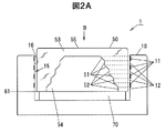
- FIG. 2A is a cross-sectional view taken along the line AA of FIG. 1, and is a cross-sectional view when the knob portion is in the first position.
- FIG. 2B is a cross-sectional view taken along the line AA of FIG. 1, and is a cross-sectional view when the knob portion is in the second position.
- FIG. 3 is an explanatory diagram showing a state of internal reflection inside the light guide.
- 4A is a plan view when the knob portion is in the first position, as viewed in the direction of arrow B in FIG. 1.
- 4B is a plan view when the knob portion is in the second position, as viewed from the direction indicated by the arrow B in FIG. 1.
- the switch device 1 is a push switch in which a knob-shaped operation unit 50 is supported and accommodated in a main body unit 10 so as to be vertically movable.
- the operation unit 50 displays the first display 110 on the display surface 55 at the first position where the push operation (press operation) is not performed, and displays the second display 120 on the display surface 55 at the second position where the push operation is performed.
- the switch device 1 according to the present embodiment is a push switch capable of display switching.
- the support unit 70 supports the operation unit 50 so as to be movable up and down.
- the support unit 70 includes a latch mechanism for holding the operation unit 50 at the first position 61 and the second position 62.
- the latch mechanism is not indispensable as long as the display can be switched in accordance with the push operation of the operation unit 50.
- the support part 70 includes a contact mechanism for functioning as a switch.
- the switch device 1 displays at least one first display unit 11 that displays first information and second information that is different from the first information.
- the second display unit 12 disposed adjacent to the operation unit 50 and the operation unit 50 having a light guide unit 53 that is moved by a push operation, and displays light from the first display unit 11 or the second display unit 12 on the display surface 55.
- At least one reflecting surface 51 that reflects toward the surface, and at least one light shielding surface 52 that shields light from the first display unit 11 or the second display unit 12 and is adjacent to the reflecting surface 51.
- the operation unit 50 is provided.
- the light guide part 53 is located in the 1st position 61 in which the light from the 1st display part 11 injects into the reflective surface 51, when satisfy
- the prescribed condition is a condition in which the first display unit 11 exhibits a display function and a person viewing the operation unit 50 visually recognizes the first display. In the present embodiment, it is a condition that the operation unit 50 is positioned at the first position 61 in the upward direction without being pushed by the operation unit 50.
- the first display 110 is a display of the first display unit 11 viewed through the display surface 55.
- the setting condition is a condition that is different from the prescribed condition, and is a condition in which the second display unit 12 exhibits a display function and a person viewing the operation unit 50 visually recognizes the second display.
- the operation unit 50 is pushed and the operation unit 50 is located at the second position 62 in the downward direction.
- the second display 120 is a display of the second display unit 12 viewed through the display surface 55.
- the 1st display part 11 is a display part provided in the side wall part 16 of the accommodating part 15 for supporting the operation part 50 so that a movement to an up-down direction is possible. As shown in FIG. 2A, the first display unit 11 is formed at the position of the side wall portion 16 corresponding to the region of each reflecting surface 51 when the operation unit 50 is positioned at the first position 61. . Further, when the operation unit 50 is located at the second position 62, the first display unit 11 does not correspond to the area of each reflection surface 51 but corresponds to the light shielding surface 52.
- the first display unit 11 displays, for example, a predetermined color, mark, character, figure, and the like. This display may be displayed in the area of the first display section 11 of the side wall section 16 by direct printing or the like. Further, a member such as a sheet may be formed in a region of the first display portion 11 of the side wall portion 16 in a state where a predetermined color, mark, character, or the like is displayed.
- the 1st display part 11 may be the structure which arrange
- a predetermined color may be displayed by a light source such as an LED, and a predetermined mark, character, figure, or the like may be displayed by a liquid crystal display panel.
- the 2nd display part 12 is a display part provided in the side wall part 16 of the accommodating part 15 for supporting the operation part 50 so that a movement to an up-down direction is possible.
- the second display unit 12 is formed at the position of the side wall 16 corresponding to the region of each reflecting surface 51 when the operation unit 50 is positioned at the second position 62. . Further, when the operation unit 50 is located at the first position 61, the second display unit 12 does not correspond to the area of each reflection surface 51 but corresponds to the light shielding surface 52.
- the second display unit 12 displays, for example, predetermined colors, marks, characters, graphics, and the like. This display may be displayed in the area of the second display section 12 of the side wall section 16 by direct printing or the like. Further, it may be formed in the region of the second display portion 12 of the side wall portion 16 in a state where a predetermined color, mark, character or the like is displayed on a member such as a sheet.
- the 2nd display part 12 may be the structure which arrange
- a predetermined color may be displayed by a light source such as an LED, and a predetermined mark, character, figure, or the like may be displayed by a liquid crystal display panel.
- the first display unit 11 and the second display unit 12 described above are provided in a plurality corresponding to each reflecting surface 51.
- the first display unit 11 and the second display unit 12 are alternately arranged along the operation direction of the operation unit 50.
- the operation unit 50 is formed in a knob shape or a button shape so as to function as a push switch operation unit.
- the operation unit 50 is formed of a light guide unit 53 that is entirely light transmissive.
- a transparent acrylic material of a light transmitting member can be used for the light guide 53.
- the operation unit 50 has a shape in which the light guide unit 53 is cut out by a space unit 54.
- a reflective surface 51 and a light shielding surface 52 are formed corresponding to the first display portion 11 and the second display portion 12.
- the reflection surface 51 and the light shielding surface 52 are alternately formed corresponding to the first display unit 11 and the second display unit 12 that are alternately arranged.
- the reflecting surface 51 is formed to be inclined with respect to the side wall portion 16, that is, the first display portion 11 and the second display portion 12.
- the reflection surface 51 reflects light from the first display unit 11 or the second display unit 12 inside the light guide unit 53. This reflection is internal reflection inside the light guide unit 53.
- FIG. 3 is a diagram illustrating a state of internal reflection inside the light guide unit 53.
- the incident angle from the first display unit 11 (or the second display unit 12) is ⁇ 1
- the reflection angle is ⁇ 2 .
- the critical angle ⁇ c is about 42 °. That is, in FIG. 3, it is preferable to set the angle of the reflecting surface 51 so that the incident angle ⁇ 1 is 42 ° or more.
- the incident angle ⁇ 1 when the incident angle ⁇ 1 is set to 42 ° or less, for example, a reflective film or the like may be formed on the air side of the light guide unit 53. Thereby, the reflectance (internal surface reflectance) in the reflective surface 51 can be improved.
- the light shielding surface 52 is a vertical surface alternately formed with the reflecting surface 51 so as not to reflect light from the first display unit 11 or the second display unit 12 upward. Is formed.
- the light shielding surface 52 is not limited to the vertical surface described above, and may be any surface having a light shielding function that does not reflect all or most of the light from the first display unit 11 or the second display unit 12 in the upward direction. Good.
- the first display 110 is displayed on the entire display surface 55 of the operation unit 50, for example, as shown in FIG. 4A.
- the first display 110 is a predetermined color of the first display unit 11 or a light emission color of the light source.
- the first display 110 is a display in which marks, characters, figures, etc. of the first display unit 11 are integrated, or a display in which marks, characters, figures, etc. displayed by liquid crystal display are integrated.
- red display is performed on the entire display surface 55 as shown in FIG. 4A.
- the second display unit 12 displays the display surface 55. Is displayed. That is, a predetermined color, mark, character, figure, or the like of the second display unit 12 is internally reflected on the reflective surface 51, and the second display 120 is displayed on the display surface 55.
- the second display 120 When viewed from the B direction in FIG. 2B, as shown in FIG. 4B, the second display 120 is displayed on the entire display surface 55 of the operation unit 50, for example.
- the second display 120 is a predetermined color of the second display unit 12 or a light emission color of the light source.
- the second display 120 is a display in which marks, characters, figures, etc. of the second display unit 12 are integrated, or a display in which marks, characters, figures, etc. displayed by liquid crystal display are integrated.
- each of the second display portions 12 is displayed in blue, as shown in FIG. 4B, blue display is performed on the entire display surface 55.
- the switch device 1 according to the present embodiment has the following effects.
- the switch device 1 according to the embodiment of the present invention displays at least one first display unit 11 that displays first information and second information that is different from the first information.
- a second display unit 12 disposed adjacent to the display unit 11 and an operation unit 50 having a light guide unit 53 that is moved by a push operation, and receives light from the first display unit 11 or the second display unit 12.
- At least one reflecting surface 51 that reflects to the display surface 55 and at least one light shielding surface 52 that shields light from the first display unit 11 or the second display unit 12 and is adjacent to the reflecting surface 51.
- an operation unit 50 having And the light guide part 53 is located in the 1st position 61 in which the light from the 1st display part 11 injects into the reflective surface 51, when satisfy
- the display of the first display unit 11 is reflected by the reflecting surface 51 and is displayed on the display surface 55 shown in FIG. 4A.
- the setting condition different from the specified condition is satisfied, The display of the second display unit 12 is reflected by the reflecting surface 51 and displayed on the display surface 55 shown in FIG. 4B.
- the switch apparatus which can switch a display can be provided.
- the configuration shown above is a simple one that switches the reflection of the first display unit 11 and the second display unit 12 in response to a push operation, a switch device that can switch display at low cost is provided. Can be provided.
- the reflection of the first display unit 11 and the second display unit 12 is performed by the internal reflection in the light guide unit 53, the design of the first display 110 and the second display 120 displayed on the display surface 55. Therefore, the appearance of the switch device is improved.
- Switch apparatus 11 1st display part 12 2nd display part 50 Operation part 51 Reflective surface 52 Light-shielding surface 53 Light guide part 55 Display surface 61 1st position 62 2nd position 110 1st display 120 2nd display
Landscapes
- Switch Cases, Indication, And Locking (AREA)
- Push-Button Switches (AREA)
Abstract
スイッチ装置(1)は、第1の情報を表示する少なくとも1つの第1表示部(11)と、第1の情報とは異なる第2の情報を表示し、第1表示部(11)に隣接して配置された第2表示部(12)と、プッシュ操作によって移動し導光部(53)を有する操作部(50)であって、第1表示部(11)または第2表示部(12)からの光を表示面(55)へと反射する少なくとも1つの反射面(51)と、第1表示部(11)または第2表示部(12)からの光を遮光し、反射面(51)に隣接するように形成された少なくとも1つの遮光面(52)とを有した操作部(50)と、を備える。導光部(53)は、規定条件を満たす場合には、第1表示部(11)からの光が反射面(51)に入射する第1位置(61)に位置し、規定条件とは異なる設定条件を満たす場合には、第2表示部(12)からの光が反射面(51)に入射する第2位置(62)に位置する。
Description
本出願は、日本国特許出願2016-207094号の優先権を主張するものであり、日本国特許出願2016-207094号の全内容を本出願に参照により援用する。
本発明は、スイッチ装置に関し、特に、表示機能を備えたスイッチ装置に関する。
スイッチノブの表面に照明表示のための照明マークを備えたスイッチ装置が知られている(例えば、特許文献1参照)。
このスイッチ装置は、押ボタン式スイッチと光源とが搭載された基板と、押ボタン式スイッチを操作するスイッチノブとを備え、スイッチノブの表示操作部を裏面から光源により照光する照光表示スイッチ装置において、スイッチノブは、透光性樹脂により表示操作部に埋め込み形成された照明マークと、照明マークを取り巻いて非透光性樹脂により形成された非表示意匠部と、表示操作部の中心部から垂下され先端がスイッチ部に連結されるロックアームと、表示操作部から垂下され先端面が光源の出射面近傍に配置される導光体と、導光体及びロックアームの基部と照明マークを連結する連結導光体とを備え、ロックアームと導光体と連結導光体が照明マークと一体に成形されて構成されている。このような構成により、導光体に照明光を入射させることにより、スイッチノブの表面の照明マークを照光表示することができるとされている。
特許文献1のスイッチ装置は、スイッチノブの内部に、ロックアームと導光体と連結導光体が照明マークと一体に成形されて内蔵されている。しかし、スイッチノブの表面の照光表示を他の表示に切り替えることはできないという問題がある。一般的に、スイッチ装置の表面の照光表示を他の表示に切り替えるには複雑な構成を要し、コストも高いという問題があった。
本発明の目的は、低コストで表示の切り替えが可能なスイッチ装置を提供することにある。
本発明は、一実施形態として、下記[1]~[6]のスイッチ装置を提供する。
[1]上記目的を達成するため、第1の情報を表示する少なくとも1つの第1表示部と、前記第1の情報とは異なる第2の情報を表示し、前記第1表示部に隣接して配置された少なくとも1つの第2表示部と、プッシュ操作によって移動する導光部であって、前記第1表示部または前記第2表示部からの光を表示面へと反射する少なくとも1つの反射面と、前記第1表示部または前記第2表示部からの光を遮光し、前記反射面に隣接するように形成された少なくとも1つの遮光面とを有した導光部と、を備え、前記導光部は、規定条件を満たす場合には、前記第1表示部からの光が前記反射面に入射する第1位置に位置し、前記規定条件とは異なる設定条件を満たす場合には、第2表示部からの光が前記反射面に入射する第2位置に位置する、スイッチ装置。
[2]前記第1表示部と前記第2表示部は、それぞれ複数個であり、前記導光部は、前記複数個の表示部にそれぞれ対応する数の前記反射面を有する、上記[1]に記載のスイッチ装置。
[3]前記反射面は、光透過部材で形成されたノブの内面反射面である、上記[1]又は[2]に記載のスイッチ装置。
[4]前記反射面は、前記第1表示部と前記第2表示部に対して傾斜を有して形成されている、上記[1]乃至[3]のいずれか1項に記載のスイッチ装置。
[5]前記反射面は、反射点における法線に対する入射角が、前記導光部の屈折率をnとしたとき、全反射するための臨界角θcとして、θc=Arcsin(1/n)で求められる角度以上となるように設定される、上記[1]乃至[4]のいずれか1項に記載のスイッチ装置。
前記導光部は、透明アクリル材であり、前記反射面は、前記入射角が42°以上となるように設定される、上記[5]に記載のスイッチ装置。
本発明の一実施形態によれば、低コストで表示の切り替えが可能なスイッチ装置を提供することができる。
(本発明の実施の形態)
図1に示すように、本発明の実施の形態に係るスイッチ装置1は、ノブ形状の操作部50が本体部10内に上下移動可能に支持されて収容されたプッシュスイッチである。操作部50は、例えば、プッシュ操作(押圧操作)されない第1位置において表示面55に第1表示110がなされ、プッシュ操作された第2位置において表示面55に第2表示120がなされる。本実施の形態に係るスイッチ装置1は、表示切り替えが可能なプッシュスイッチである。
図1に示すように、本発明の実施の形態に係るスイッチ装置1は、ノブ形状の操作部50が本体部10内に上下移動可能に支持されて収容されたプッシュスイッチである。操作部50は、例えば、プッシュ操作(押圧操作)されない第1位置において表示面55に第1表示110がなされ、プッシュ操作された第2位置において表示面55に第2表示120がなされる。本実施の形態に係るスイッチ装置1は、表示切り替えが可能なプッシュスイッチである。
図2A、図2Bに示すように、支持部70は、操作部50を上下移動可能に支持している。また、この支持部70は、操作部50を第1位置61と第2位置62において保持するためのラッチ機構を備えている。なお、操作部50のプッシュ操作に伴って表示切り替えができればよいので、ラッチ機構は必須ではない。さらに、支持部70は、スイッチとして機能するための接点機構を備えている。
本発明の実施の形態に係るスイッチ装置1は、第1の情報を表示する少なくとも1つの第1表示部11と、第1の情報とは異なる第2の情報を表示し、第1表示部11に隣接して配置された第2表示部12と、プッシュ操作によって移動し導光部53を有する操作部50であって、第1表示部11または第2表示部12からの光を表示面55へと反射する少なくとも1つの反射面51と、第1表示部11または第2表示部12からの光を遮光し、反射面51に隣接するように形成された少なくとも1つの遮光面52とを有した操作部50と、を備える。そして、導光部53は、規定条件を満たす場合には、第1表示部11からの光が反射面51に入射する第1位置61に位置し、規定条件とは異なる設定条件を満たす場合には、第2表示部12からの光が反射面51に入射する第2位置62に位置する。
規定条件とは、第1表示部11が表示機能を発揮して、操作部50を見る者が第1表示を視認する条件である。本実施の形態では、操作部50のプッシュ操作がされずに、操作部50が上方向の第1位置61に位置している条件である。第1表示110とは、表示面55を通して見る第1表示部11の表示である。
設定条件とは、規定条件とは異なる条件であって、第2表示部12が表示機能を発揮して、操作部50を見る者が第2表示を視認する条件である。本実施の形態では、操作部50のプッシュ操作がされて、操作部50が下方向の第2位置62に位置している条件である。第2表示120とは、表示面55を通して見る第2表示部12の表示である。
(第1表示部11)
第1表示部11は、操作部50を上下方向に移動可能に支持するための収容部15の側壁部16に設けられた表示部である。図2Aに示すように、この第1表示部11は、操作部50が第1位置61に位置している場合に、各反射面51の領域に対応する側壁部16の位置に形成されている。また、第1表示部11は、操作部50が第2位置62に位置している場合には、各反射面51の領域には対応せず、遮光面52に対応する。
第1表示部11は、操作部50を上下方向に移動可能に支持するための収容部15の側壁部16に設けられた表示部である。図2Aに示すように、この第1表示部11は、操作部50が第1位置61に位置している場合に、各反射面51の領域に対応する側壁部16の位置に形成されている。また、第1表示部11は、操作部50が第2位置62に位置している場合には、各反射面51の領域には対応せず、遮光面52に対応する。
第1表示部11は、例えば、所定の色、マーク、文字、図形等が表示されている。この表示は、側壁部16の第1表示部11の領域に、直接印刷等により表示されてもよい。また、シート等の部材に、所定の色、マーク、文字等が表示された状態で側壁部16の第1表示部11の領域に形成されていてもよい。
また、第1表示部11は、例えば、LED等の光源、液晶表示板等を配置して表示する構成であってもよい。LED等の光源により、所定の色を表示し、また、液晶表示板により、所定のマーク、文字、図形等を表示する構成であってもよい。
(第2表示部12)
第2表示部12は、操作部50を上下方向に移動可能に支持するための収容部15の側壁部16に設けられた表示部である。図2Bに示すように、この第2表示部12は、操作部50が第2位置62に位置している場合に、各反射面51の領域に対応する側壁部16の位置に形成されている。また、第2表示部12は、操作部50が第1位置61に位置している場合には、各反射面51の領域には対応せず、遮光面52に対応する。
第2表示部12は、操作部50を上下方向に移動可能に支持するための収容部15の側壁部16に設けられた表示部である。図2Bに示すように、この第2表示部12は、操作部50が第2位置62に位置している場合に、各反射面51の領域に対応する側壁部16の位置に形成されている。また、第2表示部12は、操作部50が第1位置61に位置している場合には、各反射面51の領域には対応せず、遮光面52に対応する。
第2表示部12は、例えば、所定の色、マーク、文字、図形等が表示されている。この表示は、側壁部16の第2表示部12の領域に、直接印刷等により表示されてもよい。また、シート等の部材に、所定の色、マーク、文字等が表示された状態で側壁部16の第2表示部12の領域に形成されていてもよい。
また、第2表示部12は、例えば、LED等の光源、液晶表示板等を配置して表示する構成であってもよい。LED等の光源により、所定の色を表示し、また、液晶表示板により、所定のマーク、文字、図形等を表示する構成であってもよい。
上記説明した第1表示部11と第2表示部12は、それぞれが各反射面51に対応して複数個とされている。また、本実施の形態では、第1表示部11と第2表示部12は、それぞれ、操作部50の操作方向に沿って交互に配置されている。
(操作部50)
操作部50は、図1、図2A、図2Bに示すように、プッシュスイッチの操作部として機能するようにノブ形状、ボタン形状として形成されている。操作部50は、全体が光透過性を有する導光部53で形成されている。導光部53は、例えば、光透過部材の透明アクリル材が使用できる。
操作部50は、図1、図2A、図2Bに示すように、プッシュスイッチの操作部として機能するようにノブ形状、ボタン形状として形成されている。操作部50は、全体が光透過性を有する導光部53で形成されている。導光部53は、例えば、光透過部材の透明アクリル材が使用できる。
操作部50は、図2A、図2Bに示すように、導光部53を空間部54でくり抜いた形状とされている。
導光部53において、図2A、図2Bに示すように、反射面51、遮光面52が、第1表示部11と第2表示部12に対応して形成されている。本実施の形態では、交互に配置された第1表示部11と第2表示部12に対応して、反射面51と遮光面52が交互に形成されている。
反射面51は、図2A、図2Bに示すように、側壁部16すなわち第1表示部11、第2表示部12に対して傾斜を有して形成されている。反射面51は、導光部53の内部で第1表示部11または第2表示部12からの光を反射する。この反射は、導光部53の内部での内面反射である。
反射面51における内面反射は、反射の効率を考えると、全反射が好ましい。図3は、導光部53の内部での内面反射の状態を示す図である。反射点Pにおける法線Nに対して、第1表示部11(または第2表示部12)からの入射角をθ1、反射角をθ2とする。また、本実施の形態で導光部53として使用する透明アクリル材の屈折率をn=1.49とする。この場合の全反射条件を満たす臨界角θcは、臨界角θc=Arcsin(1/n)で求められる。臨界角θcは、約42°となる。すなわち、図3において、入射角θ1が、42°以上となるように反射面51の角度を設定することが好ましい。
また、図3において、入射角θ1を42°以下とする場合は、例えば、導光部53の空気(air)側に、反射膜等を形成してもよい。これにより、反射面51における反射率(内面反射率)を向上させることができる。
(遮光面52)
遮光面52は、図2A、図2Bに示すように、反射面51と交互に形成された垂直面であり、第1表示部11または第2表示部12からの光を上方向へ反射しないように形成されている。なお、遮光面52は、上記した垂直面には限られず、第1表示部11または第2表示部12からの光の全部または大部分を上方向へ反射しない遮光機能を有した面であればよい。
遮光面52は、図2A、図2Bに示すように、反射面51と交互に形成された垂直面であり、第1表示部11または第2表示部12からの光を上方向へ反射しないように形成されている。なお、遮光面52は、上記した垂直面には限られず、第1表示部11または第2表示部12からの光の全部または大部分を上方向へ反射しない遮光機能を有した面であればよい。
(スイッチ装置1の動作)
(プッシュ操作がされない場合)
図2Aに示すように、操作部50のプッシュ操作がされずに、操作部50が上方向の第1位置61に位置している規定条件を満たす場合には、第1表示部11が表示面55に表示される。すなわち、第1表示部11の所定の色、マーク、文字、図形等が反射面51において内面反射され、第1表示110が表示面55に表示される。
(プッシュ操作がされない場合)
図2Aに示すように、操作部50のプッシュ操作がされずに、操作部50が上方向の第1位置61に位置している規定条件を満たす場合には、第1表示部11が表示面55に表示される。すなわち、第1表示部11の所定の色、マーク、文字、図形等が反射面51において内面反射され、第1表示110が表示面55に表示される。
図2AのB方向から見ると、図4Aに示すように、操作部50の表示面55には、例えば全面に、第1表示110が表示される。この第1表示110は、第1表示部11の所定の色、あるいは、光源の発光色である。また、第1表示110は、第1表示部11のマーク、文字、図形等が統合された表示、あるいは、液晶表示により表示されたマーク、文字、図形等が統合された表示である。
具体例としては、第1表示部11がそれぞれ赤色に表示されている場合は、図4Aに示すように、表示面55の全面に、赤色表示がされる。
(プッシュ操作がされた場合)
図2Bに示すように、操作部50のプッシュ操作がされて、操作部50が下方向の第2位置62に位置している設定条件を満たす場合には、第2表示部12が表示面55に表示される。すなわち、第2表示部12の所定の色、マーク、文字、図形等が反射面51において内面反射され、第2表示120が表示面55に表示される。
図2Bに示すように、操作部50のプッシュ操作がされて、操作部50が下方向の第2位置62に位置している設定条件を満たす場合には、第2表示部12が表示面55に表示される。すなわち、第2表示部12の所定の色、マーク、文字、図形等が反射面51において内面反射され、第2表示120が表示面55に表示される。
図2BのB方向から見ると、図4Bに示すように、操作部50の表示面55には、例えば全面に、第2表示120が表示される。この第2表示120は、第2表示部12の所定の色、あるいは、光源の発光色である。また、第2表示120は、第2表示部12のマーク、文字、図形等が統合された表示、あるいは、液晶表示により表示されたマーク、文字、図形等が統合された表示である。
具体例としては、第2表示部12がそれぞれ青色に表示されている場合は、図4Bに示すように、表示面55の全面に、青色表示がされる。
(本発明の実施の形態の効果)
本実施の形態に係るスイッチ装置1は以下のような効果を有する。
(1)本発明の実施の形態に係るスイッチ装置1は、第1の情報を表示する少なくとも1つの第1表示部11と、第1の情報とは異なる第2の情報を表示し、第1表示部11に隣接して配置された第2表示部12と、プッシュ操作によって移動し導光部53を有する操作部50であって、第1表示部11または第2表示部12からの光を表示面55へと反射する少なくとも1つの反射面51と、第1表示部11または第2表示部12からの光を遮光し、反射面51に隣接するように形成された少なくとも1つの遮光面52とを有した操作部50と、を備える。そして、導光部53は、規定条件を満たす場合には、第1表示部11からの光が反射面51に入射する第1位置61に位置し、規定条件とは異なる設定条件を満たす場合には、第2表示部12からの光が反射面51に入射する第2位置62に位置するように構成されている。これにより、規定条件を満たす場合は、第1表示部11の表示が反射面51で反射されて図4Aで示す表示面55に表示され、一方、規定条件とは異なる設定条件を満たす場合は、第2表示部12の表示が反射面51で反射されて図4Bで示す表示面55に表示される。これにより、表示の切り替えが可能なスイッチ装置を提供することができる。
(2)上記示した構成は、プッシュ操作に対応して、第1表示部11と第2表示部12の反射を切り替える簡単なものであるため、低コストで表示の切り替えが可能なスイッチ装置を提供することができる。
(3)第1表示部11と第2表示部12の反射を、導光部53内での内面反射で行なうので、表示面55に表示される第1表示110、第2表示120の意匠性がよく、スイッチ装置の見栄えが向上するという効果を有する。
本実施の形態に係るスイッチ装置1は以下のような効果を有する。
(1)本発明の実施の形態に係るスイッチ装置1は、第1の情報を表示する少なくとも1つの第1表示部11と、第1の情報とは異なる第2の情報を表示し、第1表示部11に隣接して配置された第2表示部12と、プッシュ操作によって移動し導光部53を有する操作部50であって、第1表示部11または第2表示部12からの光を表示面55へと反射する少なくとも1つの反射面51と、第1表示部11または第2表示部12からの光を遮光し、反射面51に隣接するように形成された少なくとも1つの遮光面52とを有した操作部50と、を備える。そして、導光部53は、規定条件を満たす場合には、第1表示部11からの光が反射面51に入射する第1位置61に位置し、規定条件とは異なる設定条件を満たす場合には、第2表示部12からの光が反射面51に入射する第2位置62に位置するように構成されている。これにより、規定条件を満たす場合は、第1表示部11の表示が反射面51で反射されて図4Aで示す表示面55に表示され、一方、規定条件とは異なる設定条件を満たす場合は、第2表示部12の表示が反射面51で反射されて図4Bで示す表示面55に表示される。これにより、表示の切り替えが可能なスイッチ装置を提供することができる。
(2)上記示した構成は、プッシュ操作に対応して、第1表示部11と第2表示部12の反射を切り替える簡単なものであるため、低コストで表示の切り替えが可能なスイッチ装置を提供することができる。
(3)第1表示部11と第2表示部12の反射を、導光部53内での内面反射で行なうので、表示面55に表示される第1表示110、第2表示120の意匠性がよく、スイッチ装置の見栄えが向上するという効果を有する。
以上、本発明のいくつかの実施の形態を説明したが、これらの実施の形態は、一例に過ぎず、請求の範囲に係る発明を限定するものではない。これら新規な実施の形態は、その他の様々な形態で実施されることが可能であり、本発明の要旨を逸脱しない範囲で、種々の省略、置き換え、変更等を行うことができる。また、これら実施の形態の中で説明した特徴の組合せの全てが発明の課題を解決するための手段に必須であるとは限らない。さらに、これら実施の形態は、発明の範囲及び要旨に含まれるとともに、請求の範囲に記載された発明とその均等の範囲に含まれる。
1 スイッチ装置
11 第1表示部
12 第2表示部
50 操作部
51 反射面
52 遮光面
53 導光部
55 表示面
61 第1位置
62 第2位置
110 第1表示
120 第2表示
11 第1表示部
12 第2表示部
50 操作部
51 反射面
52 遮光面
53 導光部
55 表示面
61 第1位置
62 第2位置
110 第1表示
120 第2表示
Claims (6)
- 第1の情報を表示する少なくとも1つの第1表示部と、
前記第1の情報とは異なる第2の情報を表示し、前記第1表示部に隣接して配置された少なくとも1つの第2表示部と、
プッシュ操作によって移動する導光部であって、前記第1表示部または前記第2表示部からの光を表示面へと反射する少なくとも1つの反射面と、前記第1表示部または前記第2表示部からの光を遮光し、前記反射面に隣接するように形成された少なくとも1つの遮光面とを有した導光部と、を備え、
前記導光部は、規定条件を満たす場合には、前記第1表示部からの光が前記反射面に入射する第1位置に位置し、前記規定条件とは異なる設定条件を満たす場合には、第2表示部からの光が前記反射面に入射する第2位置に位置する、スイッチ装置。 - 前記第1表示部と前記第2表示部は、それぞれ複数個であり、前記導光部は、前記複数個の表示部にそれぞれ対応する数の前記反射面を有する、請求項1に記載のスイッチ装置。
- 前記反射面は、光透過部材で形成されたノブの内面反射面である、請求項1又は2に記載のスイッチ装置。
- 前記反射面は、前記第1表示部と前記第2表示部に対して傾斜を有して形成されている、請求項1乃至3のいずれか1項に記載のスイッチ装置。
- 前記反射面は、反射点における法線に対する入射角が、前記導光部の屈折率をnとしたとき、全反射するための臨界角θcとして、θc=Arcsin(1/n)で求められる角度以上となるように設定される、請求項1乃至4のいずれか1項に記載のスイッチ装置。
- 前記導光部は、透明アクリル材であり、
前記反射面は、前記入射角が42°以上となるように設定される、請求項5に記載のスイッチ装置。
Applications Claiming Priority (2)
| Application Number | Priority Date | Filing Date | Title |
|---|---|---|---|
| JP2016-207094 | 2016-10-21 | ||
| JP2016207094A JP2018067513A (ja) | 2016-10-21 | 2016-10-21 | スイッチ装置 |
Publications (1)
| Publication Number | Publication Date |
|---|---|
| WO2018074333A1 true WO2018074333A1 (ja) | 2018-04-26 |
Family
ID=62018573
Family Applications (1)
| Application Number | Title | Priority Date | Filing Date |
|---|---|---|---|
| PCT/JP2017/037070 Ceased WO2018074333A1 (ja) | 2016-10-21 | 2017-10-12 | スイッチ装置 |
Country Status (2)
| Country | Link |
|---|---|
| JP (1) | JP2018067513A (ja) |
| WO (1) | WO2018074333A1 (ja) |
Families Citing this family (1)
| Publication number | Priority date | Publication date | Assignee | Title |
|---|---|---|---|---|
| CN108847367B (zh) * | 2018-07-03 | 2021-02-05 | Tcl通力电子(惠州)有限公司 | 按键和音箱设备 |
Citations (6)
| Publication number | Priority date | Publication date | Assignee | Title |
|---|---|---|---|---|
| JPS57126128U (ja) * | 1981-01-28 | 1982-08-06 | ||
| JPS59170327U (ja) * | 1983-04-28 | 1984-11-14 | 日本航空電子工業株式会社 | 照光機構 |
| JPS62167318U (ja) * | 1986-04-14 | 1987-10-23 | ||
| JPH04351814A (ja) * | 1991-05-29 | 1992-12-07 | Canon Inc | 電子機器の入力キー |
| JP2013093155A (ja) * | 2011-10-25 | 2013-05-16 | Tokai Rika Co Ltd | スイッチ装置 |
| JP2013254597A (ja) * | 2012-06-05 | 2013-12-19 | Yazaki Corp | 照光表示スイッチ装置 |
-
2016
- 2016-10-21 JP JP2016207094A patent/JP2018067513A/ja active Pending
-
2017
- 2017-10-12 WO PCT/JP2017/037070 patent/WO2018074333A1/ja not_active Ceased
Patent Citations (6)
| Publication number | Priority date | Publication date | Assignee | Title |
|---|---|---|---|---|
| JPS57126128U (ja) * | 1981-01-28 | 1982-08-06 | ||
| JPS59170327U (ja) * | 1983-04-28 | 1984-11-14 | 日本航空電子工業株式会社 | 照光機構 |
| JPS62167318U (ja) * | 1986-04-14 | 1987-10-23 | ||
| JPH04351814A (ja) * | 1991-05-29 | 1992-12-07 | Canon Inc | 電子機器の入力キー |
| JP2013093155A (ja) * | 2011-10-25 | 2013-05-16 | Tokai Rika Co Ltd | スイッチ装置 |
| JP2013254597A (ja) * | 2012-06-05 | 2013-12-19 | Yazaki Corp | 照光表示スイッチ装置 |
Also Published As
| Publication number | Publication date |
|---|---|
| JP2018067513A (ja) | 2018-04-26 |
Similar Documents
| Publication | Publication Date | Title |
|---|---|---|
| US10227005B2 (en) | Vehicular display device | |
| CN104718097B (zh) | 光引导装置 | |
| JP5835559B2 (ja) | 指針式表示装置 | |
| CN203377146U (zh) | 背光装置及使用其的发光键盘 | |
| TWI523060B (zh) | 發光鍵盤裝置 | |
| US12175828B2 (en) | Gaming machine | |
| CN101802951A (zh) | 显示装置和按键装置 | |
| JP2011113695A (ja) | イルミネーション装置及び電子機器 | |
| WO2018074333A1 (ja) | スイッチ装置 | |
| CN113260908A (zh) | 显示装置、照明装置、导光部件及导光构造 | |
| JP5247500B2 (ja) | 照明装置及び電子機器 | |
| JP2011047790A (ja) | 表示装置 | |
| JP2009508152A (ja) | エレクトロオプティカルディスプレイを備えた表示器 | |
| JP3182212U (ja) | 照光表示装置 | |
| CN204340854U (zh) | 字符板照明构造 | |
| JP4806950B2 (ja) | メータ装置 | |
| JP6085779B2 (ja) | 光学構造体 | |
| JP2010170999A (ja) | 光源装置及び電子機器 | |
| TWM469606U (zh) | 用於發光鍵盤之背光裝置 | |
| JP2005345548A (ja) | 内照式表示構造及び内照式表示方法 | |
| JP6766591B2 (ja) | 発光装置 | |
| JP6135921B2 (ja) | 表示部材及び表示装置 | |
| JP2013242266A (ja) | 計器用表示装置 | |
| US20230079921A1 (en) | Operation button for gaming machine, and operation deck for gaming machine provided with the operation button | |
| JP7234826B2 (ja) | 表示装置及び電子機器 |
Legal Events
| Date | Code | Title | Description |
|---|---|---|---|
| 121 | Ep: the epo has been informed by wipo that ep was designated in this application |
Ref document number: 17862914 Country of ref document: EP Kind code of ref document: A1 |
|
| NENP | Non-entry into the national phase |
Ref country code: DE |
|
| 122 | Ep: pct application non-entry in european phase |
Ref document number: 17862914 Country of ref document: EP Kind code of ref document: A1 |