WO2018073982A1 - 中継装置及びその中継方法 - Google Patents
中継装置及びその中継方法 Download PDFInfo
- Publication number
- WO2018073982A1 WO2018073982A1 PCT/JP2016/087214 JP2016087214W WO2018073982A1 WO 2018073982 A1 WO2018073982 A1 WO 2018073982A1 JP 2016087214 W JP2016087214 W JP 2016087214W WO 2018073982 A1 WO2018073982 A1 WO 2018073982A1
- Authority
- WO
- WIPO (PCT)
- Prior art keywords
- relay
- amplitude
- phase
- base station
- relay device
- Prior art date
- Legal status (The legal status is an assumption and is not a legal conclusion. Google has not performed a legal analysis and makes no representation as to the accuracy of the status listed.)
- Ceased
Links
Images





Classifications
-
- H—ELECTRICITY
- H04—ELECTRIC COMMUNICATION TECHNIQUE
- H04W—WIRELESS COMMUNICATION NETWORKS
- H04W16/00—Network planning, e.g. coverage or traffic planning tools; Network deployment, e.g. resource partitioning or cells structures
- H04W16/24—Cell structures
- H04W16/28—Cell structures using beam steering
-
- H—ELECTRICITY
- H04—ELECTRIC COMMUNICATION TECHNIQUE
- H04B—TRANSMISSION
- H04B7/00—Radio transmission systems, i.e. using radiation field
- H04B7/02—Diversity systems; Multi-antenna system, i.e. transmission or reception using multiple antennas
- H04B7/10—Polarisation diversity; Directional diversity
-
- H—ELECTRICITY
- H04—ELECTRIC COMMUNICATION TECHNIQUE
- H04B—TRANSMISSION
- H04B17/00—Monitoring; Testing
- H04B17/10—Monitoring; Testing of transmitters
- H04B17/11—Monitoring; Testing of transmitters for calibration
- H04B17/12—Monitoring; Testing of transmitters for calibration of transmit antennas, e.g. of the amplitude or phase
-
- H—ELECTRICITY
- H04—ELECTRIC COMMUNICATION TECHNIQUE
- H04B—TRANSMISSION
- H04B17/00—Monitoring; Testing
- H04B17/40—Monitoring; Testing of relay systems
-
- H—ELECTRICITY
- H04—ELECTRIC COMMUNICATION TECHNIQUE
- H04B—TRANSMISSION
- H04B7/00—Radio transmission systems, i.e. using radiation field
- H04B7/02—Diversity systems; Multi-antenna system, i.e. transmission or reception using multiple antennas
- H04B7/04—Diversity systems; Multi-antenna system, i.e. transmission or reception using multiple antennas using two or more spaced independent antennas
- H04B7/06—Diversity systems; Multi-antenna system, i.e. transmission or reception using multiple antennas using two or more spaced independent antennas at the transmitting station
- H04B7/0613—Diversity systems; Multi-antenna system, i.e. transmission or reception using multiple antennas using two or more spaced independent antennas at the transmitting station using simultaneous transmission
- H04B7/0615—Diversity systems; Multi-antenna system, i.e. transmission or reception using multiple antennas using two or more spaced independent antennas at the transmitting station using simultaneous transmission of weighted versions of same signal
- H04B7/0617—Diversity systems; Multi-antenna system, i.e. transmission or reception using multiple antennas using two or more spaced independent antennas at the transmitting station using simultaneous transmission of weighted versions of same signal for beam forming
-
- H—ELECTRICITY
- H04—ELECTRIC COMMUNICATION TECHNIQUE
- H04B—TRANSMISSION
- H04B7/00—Radio transmission systems, i.e. using radiation field
- H04B7/14—Relay systems
- H04B7/15—Active relay systems
- H04B7/155—Ground-based stations
- H04B7/15528—Control of operation parameters of a relay station to exploit the physical medium
-
- H—ELECTRICITY
- H04—ELECTRIC COMMUNICATION TECHNIQUE
- H04W—WIRELESS COMMUNICATION NETWORKS
- H04W84/00—Network topologies
- H04W84/02—Hierarchically pre-organised networks, e.g. paging networks, cellular networks, WLAN [Wireless Local Area Network] or WLL [Wireless Local Loop]
- H04W84/04—Large scale networks; Deep hierarchical networks
- H04W84/042—Public Land Mobile systems, e.g. cellular systems
- H04W84/047—Public Land Mobile systems, e.g. cellular systems using dedicated repeater stations
-
- H—ELECTRICITY
- H04—ELECTRIC COMMUNICATION TECHNIQUE
- H04W—WIRELESS COMMUNICATION NETWORKS
- H04W92/00—Interfaces specially adapted for wireless communication networks
- H04W92/16—Interfaces between hierarchically similar devices
- H04W92/20—Interfaces between hierarchically similar devices between access points
Definitions
- the present invention relates to a relay device that relays communication between a terminal device and a donor base station, and a relay method thereof.
- the communication standard for mobile communications there is a third generation mobile phone (3G) standards and LTE (L ong T erm E volution ) and the like.
- 3G third generation mobile phone
- LTE Long T erm E volution
- Various usable frequency bands are set for each communication standard, and specifications of each frequency band are strictly determined.
- a relay device is used to improve coverage when the terminal device is used indoors.
- One of a plurality of frequency bands defined in the communication standard is selected for the access radio that is radio communication with the terminal device of the relay apparatus and the backhaul radio that is radio communication with the donor base station.
- Patent Document 1 discloses a technique of performing beamforming for signal transmission related to backhaul radio using a plurality of antennas provided in a relay apparatus.
- the radio communication of the access radio is in beamforming in the backhaul radio. It turns out that it has a considerable influence. That is, when beam forming is performed while the access radio is operating in the relay device, harmonics generated in the radio communication in the access radio performed at a short distance interfere with the radio communication in the backhaul radio. It will end up. Therefore, there is a possibility that beam forming cannot be performed accurately.
- the present invention has been made in view of the above circumstances, and an object of the present invention is to provide a relay apparatus and a relay method thereof capable of accurately performing beamforming in wireless communication from the relay apparatus to the donor base station.
- a relay device is a relay device that relays communication between a terminal device and a donor base station, from the donor base station to the relay device.
- An amplitude and phase measuring unit for measuring the amplitude and phase of wireless communication, and adjusting the amplitude and phase from a plurality of antennas used in the relay device based on the measured amplitude and phase, to the donor base station
- a beam adjustment unit that performs adjustment for beam forming, and measures the amplitude and phase in a time zone in which the terminal device is not located with respect to the relay device, and for the donor base station Make adjustments for beamforming.
- the amplitude and phase measurement unit measures the amplitude and phase of the wireless communication (downlink) from the donor base station to the relay device in a time zone in which the terminal device is not located, the downlink amplitude and The phase is measured correctly. Therefore, from a plurality of antennas adjusted to have the same amplitude and opposite phase as that of the downlink, wireless communication (uplink) from the relay apparatus using the same frequency band to the donor base station can be performed with the highest combined reception quality. Since it is known that it can be provided, adjustment for uplink beamforming can be performed accurately.
- the relay device includes a timer for starting the amplitude and phase measurement unit and the beam adjustment unit, and the timer is set to start at a time zone in which it is estimated that the terminal device is not located in the relay device. May be.
- the relay device may detect that the terminal device is not located after the timer is started, and measure the amplitude and phase after stopping the access radio between the relay device and the terminal device.
- the relay device includes a detection unit that detects the presence / absence of the terminal device, and measures the amplitude and phase when the detection unit detects that the terminal device has not been in the relay device for a certain period of time.
- the donor base station may be adjusted for beam forming.
- the relay device may measure the amplitude and phase after detecting that the terminal device has not been located for a certain period of time and then stopping the access radio between the relay device and the terminal device.
- the relay device may restart the access radio after adjusting for beamforming.
- a relay method for a relay device includes a step of measuring the amplitude and phase of wireless communication from a donor base station to a relay device, and a plurality of relay devices used based on the measured amplitude and phase. Adjusting the amplitude and phase from the antenna and adjusting the beamforming for wireless communication from the relay device to the donor base station, and the terminal device is located in the relay device. During the time period when it is not, adjustment for beam forming is performed by measuring the amplitude and phase.
- the present invention it is possible to provide a relay apparatus and a relay method thereof that can accurately perform beamforming in wireless communication from the relay apparatus to the donor base station.
- Explanatory drawing which shows the radio
- the block diagram of the relay apparatus which concerns on 2nd Embodiment.
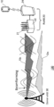
- FIG. 1 is an explanatory diagram showing a radio network configuration of a mobile communication system.
- the radio network of the mobile communication system 100 includes a terminal device 10, a relay device 20, and a donor base station 30.
- the terminal device 10 is a mobile communication terminal such as a smartphone or a mobile phone.
- FIG. 1 shows a state in which the access radio is operating and the terminal device 10 is within the communicable range of the relay device 20.
- Relay device 20 is also called a whole in the sense that the node that relays the donor base station 30 and the terminal device 10 and ReNB (Re lay N ode B) .
- the relay device 20 includes a relay node (Relay Node) 22 that executes radio communication related to backhaul radio with the donor base station 30 and an access node that executes radio communication related to access radio with the terminal device 10.
- (Access Node) 24 is provided.
- the relay node 22 and the access node 24 are configured as independent and independent devices, but may be configured as an integrated device that integrates both functions.
- the relay node 22 and the access node 24 handle packet data as a radio signal.
- a packet communication service for example, a voice packet communication service, a multimedia service, etc.
- the relay node 22 is a node that constitutes one node in the wireless network and establishes backhaul wireless communication with the donor base station 30.
- the relay node 22 also referred to as customer premises equipment CPE (C ustomer P grasps E quipment ).
- CPE customer premises equipment
- the relay node 22 can establish communication with the donor base station 30 by selecting one of a plurality of frequency bands that are determined to be selectable in the communication standard.
- the relay node 22 includes an antenna group 21.
- the antenna group 21 is an aggregate of a plurality of antenna elements.
- the relay node 22 is configured to independently control the amplitude and phase of excitation in each antenna element. Directivity of radio signals received by the antenna group 21 can be controlled by a combination of antenna elements to be used among a plurality of antenna elements. Therefore, by appropriately selecting the antenna element to be used, the signal gain for a radio signal from a specific direction can be increased.
- the access node 24 is a node that constitutes one node in the wireless network and establishes access wireless communication with the terminal device 10.
- Access node 24, in the LTE standard is also referred to as HeNB (H ome eN ode B) and the femtocell (F emto C ell) base station.
- the cell size formed by the access node 24 is smaller than that of the donor base station 30, and a communication area having a radius of several meters to several tens of meters is constructed.
- the operation of the access radio of the access node 24 is effective for the beam forming in the relay node 22. In this embodiment, a method for preventing this is provided.
- the radio signal has the same propagation path in the radio communication (downlink Dn) from the donor base station to the relay node 22 and in the radio communication (uplink Up) from the relay node 22 to the donor base station. Is known to go through.
- the signals in the same frequency band are used in the downlink Dn and the uplink Up, if the amplitude and phase of the uplink Up are set to the same amplitude and opposite phase as those of the downlink Dn in the relay node 22, It has been found that the directivity of the radio wave in the downlink Dn is similar to the directivity of the radio wave in the uplink Up.
- the donor and the uplink Up have the same amplitude and phase as the downlink Dn.
- the base station 30 can provide wireless communication with the highest combined reception quality.
- the radio communication beam for the donor base station 30 in the uplink Up can be shaped and concentrated and transmitted with strong radio waves, that is, suitable beam forming can be performed.
- FIG. 2 is a block diagram of the relay node 22 according to the present embodiment.
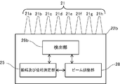
- the relay node 22 includes an amplitude and phase measurement unit 25 that measures the amplitude and phase of wireless communication, and a detection unit that detects that the terminal device 10 is not located in the access node 24. 26, a beam adjusting unit 27 that performs adjustment for beam forming with respect to the donor base station 30, and a timer 27 that activates the amplitude and phase measuring unit 25 and the beam adjusting unit 28.
- the amplitude and phase measurement unit 25 is, for example, an adaptive array that measures the amplitude and phase of the downlink Dn radio signal.
- the detection unit 26 Upon receiving an inquiry from the timer 27, the detection unit 26 is a means for detecting whether or not the terminal device 10 is located in the access node 24 and returning the detection result to the timer 27.
- the timer 27 is a time measuring unit that activates the amplitude and phase measurement unit 25 and the beam adjustment unit 27 in a time zone in which the terminal device 10 is not located in the access node 24 of the relay device 20. Specifically, the timer 27 sends the detection unit 26 to the access node 24 in a time zone set in advance as a time zone where there is a high possibility that the terminal device 10 is not located in the access node 24. The terminal device 10 is inquired as to whether or not the terminal device 10 is not in the service area. When it is confirmed by the detection unit 26 that the terminal device 10 is not located in the access node 24, the access radio by the access node 24 is stopped, and the amplitude and phase measurement unit 25 and the beam adjustment unit are stopped. 27 is activated. Further, the timer 27 restarts the access radio by the access node 24 when the adjustment for beam forming by the amplitude and phase measurement unit 25 and the beam adjustment unit 27 is completed.
- the reason why it is preferable to stop the access radio when the amplitude and phase measurement unit 25 measures the amplitude and phase of the downlink Dn is as follows. Factors that influence the measurement of the amplitude and phase of backhaul radio are generally as follows: 1) The access radio is operating (that is, the access node 24 (femtocell base station) of the relay device 20 is started up and the pilot channel or broadcast is performed). 2) that the terminal device 10 communicates via the femtocell base station when it is in service, and 3) that the voice or data communication is transmitted to the femto. There are things that go through cell base stations.
- the terminal device 10 cannot be located in the access node 24 (femtocell base station) of the relay device 20, and the communication service cannot be used. Therefore, when measuring the amplitude and phase of the backhaul radio, it is preferable to stop the access radio as in this embodiment in order to ensure the accuracy of the measurement results.
- the beam adjustment unit 28 adjusts the amplitude and phase from the plurality of antenna elements to the same amplitude and opposite phase as those of the downlink Dn measured by the amplitude and phase measurement unit 25, thereby allowing the donor base station 30 in the uplink Up.
- adjustment for beam forming is performed by shaping and concentrating radio communication beams and sending them with strong radio waves.
- Examples of the antenna group 21 and the beam adjusting unit 28 include an adaptive (adaptive) array system that performs adaptive control of the directivity characteristics of the antenna group 21. Details will be described later.
- the donor base station 30 is configured to establish direct access wireless communication with the terminal device 10 in addition to establishing wireless communication with the relay node 22.
- the donor base station 30 constructs a communication area having a radius of several hundred meters to several tens of kilometers.
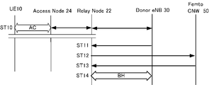
- FIG. 3 is a sequence diagram of the operation of a normal relay device. As shown in FIG. 3, when the terminal device 10 that performs only WiFi communication is present in the access node 24 of the relay device 20, a WiFi session is generated and the access between the terminal device 10 and the relay device 20 is performed. Access communication (AC) is executed with the node 24 (ST10).
- AC Access communication
- the relay node 22 acquires connection destination identification information from the donor base station 30 (ST11).
- the relay node 22 connects to the donor base station 30 based on the connection destination identification information (ST12). At that time, the relay node 22 transmits a major report to a femto core network (Femto CNW) 50 that performs failure management, quality management, and start / stop control management regarding the relay device 20.
- Femto CNW femto core network
- the femto core network 50 determines the communication quality and the communication amount with the relay node 22 based on the major report from the relay node 22 (ST13). And a connection is established between the relay node 22 and the donor base station 30, and backhaul communication (BH) is performed (ST14).
- BH backhaul communication
- the femto core network 50 of the donor base station 30 continues to determine the communication quality and the communication amount between the relay node 22 and the donor base station 30 based on the major report from the relay node 22.
- the relay node 22 since the relay node 22 appropriately selects the amplitude and phase from the antenna element used in the uplink Up wireless communication with the donor base station 30, in the wireless communication related to the backhaul wireless The composite reception quality is maintained high, and it is possible to ensure communication with high communication quality and a suitable communication speed.
- an array antenna in which a plurality of antenna elements are arranged and the amplitude and phase of excitation of each antenna element are controlled independently is employed as the antenna 21.
- the beam adjustment unit 28 for example, an adaptive array system that performs adaptive control of the directivity characteristics of the array antenna is employed.
- a k and ⁇ k are a weight and a phase shift amount applied to the k-th element, respectively.
- D ( ⁇ ) is an array factor.
- the directivity of the entire array is represented by the product of the directivity g ( ⁇ ) of the element and the array factor D ( ⁇ ). This is called pattern multiplication. Therefore, when all the antenna elements are the same and are placed in the same direction, the directivity of the entire array can be adjusted effectively by controlling the array factor.
- the phase shift amount ⁇ k is generally set to Choose. That is, the phase at the output of the phase shifter with respect to the desired signal is determined to be uniform over each element. In the other directions, the output phases of the elements do not coincide with each other, and a certain amount of cancellation is performed. In this way, when an array antenna is used, the gain for a desired signal is increased. However, if the element spacing is large, Even when the angle ⁇ gm satisfies the above, they are added in phase with each other, so that a large array response value is generated. This is called a grating lobe (see FIG. 9B), and usually preventive measures are taken at the design stage.
- the array factor of Equation (3) is in the form of an integer polynomial, so that A k is appropriately selected using mathematical means, and the side lobes are generalized. It is possible to reduce the response value in the direction of arrival for a specific strong unnecessary wave to zero.
- a system based on this concept is an adaptive array.
- FIG. 4 is a flowchart of the relay method of the relay device according to the first embodiment.
- FIG. 5 is an explanatory diagram of the measurement failure of the amplitude and phase due to the operation of the access radio.
- the radio communication (downlink Dn) from the donor base station 30 to the relay node 22 and the radio communication (uplink Up) from the relay node 22 to the donor base station 30 pass through the same propagation path. I know that.
- the amplitude and phase of the radio communication of the downlink Dn are measured, and the same amplitude and opposite phase as those of the downlink Dn are also used for the uplink Up, thereby performing radio communication with higher combined reception quality. I will do it.
- the relay node 22 measures the uplink Uplink while measuring the amplitude and phase of the radio communication of the downlink Dn. If an attempt is made to adjust the combination of antennas, harmonics from the access radio of the access node 24 performed at a short distance cause interference If. Accordingly, the amplitude and phase of the downlink Dn wireless communication cannot be correctly measured, and the uplink Up beamforming cannot be accurately performed.
- the timer 27 is activated in a time zone in which it is estimated that the terminal device 10 is not located in the relay device 20, and the terminal device 10 is not located in a predetermined activation time.
- the access radio is stopped, and beam forming is performed.
- the activation time of the timer 27 provided in the relay device 20 is set to a time zone in which it is estimated that the terminal device 10 is not located in the relay device 20. (ST21).
- a time zone a time zone during which the terminal device 10 is not used on a daily basis, for example, a midnight time zone, can be set uniformly.
- a specific terminal device 10 that can be located in the relay device 20 can be limited to the relay device 20 such as when the relay device 20 is set not in a public place but in a private house, the specific terminal device 10 is used. It is also possible to set the time period for the timer 27 in advance by setting the time period in which the specific terminal device 10 is least likely to be used.
- the amplitude and phase measurement by the amplitude and phase measurement unit 25 is performed until the access radio is stopped. Absent.
- the access radio is stopped (ST23).
- measurement of amplitude and phase by the amplitude and phase measurement unit 25 is started (ST24).
- the amplitude and phase measurement unit 25 measures the amplitude and phase of the downlink Dn from the donor base station 30 to the relay node 22.
- the beam adjustment unit 28 measures the amplitude and phase of the downlink Dn, and adjusts the uplink Up from the plurality of antenna elements so as to have the same amplitude and opposite phase as the downlink Dn (ST25).
- the access radio is restarted (ST26).
- the relay node 22 adjusts the amplitude and phase from a plurality of antennas (ST25), and shapes and concentrates the uplink Up beam to the donor base station 30 and sends it with strong radio waves to accurately perform beam forming. (ST27).
- the time setting of the timer indicates that the terminal device 10 is not located in a time zone where the terminal device 10 is not located. Detection and access radio are stopped, and the amplitude and phase measurement unit 25 measures the amplitude and phase of the downlink Dn from the donor base station 30 to the relay node 22, so that the amplitude and phase of the downlink Dn are correctly measured. . Therefore, the uplink Up beam forming from the relay node 22 to the donor base station 30 can be performed accurately without being affected by the harmonics from the access radio.
- the configuration of the relay device according to the second embodiment will be described.
- the beam forming is executed based on the setting by the timer.
- the second embodiment detects that the terminal device 10 has not been located for a certain period of time without depending on the timer. It differs from the first embodiment in that it determines whether or not it can be executed.
- FIG. 6 is a block diagram of the relay device according to the second embodiment.
- the same components as those in the first embodiment are denoted by the same reference numerals.
- the relay node 22b according to the second embodiment does not include a timer, and includes a detection unit 26b that detects that the terminal device 10 is not located in the relay device 20 for a certain period of time. Different from the first embodiment.
- the amplitude and phase measurement unit 25 and the beam adjustment unit 28 operate in the same manner as in the first embodiment.
- FIG. 7 is a flowchart of the relay method of the relay device according to the second embodiment.
- the detection unit 26b detects that the terminal device 10 is not located in the relay device 20 for a certain period (ST31). If the terminal device 10 has not been in the area for a certain period of time, it is presumed that the terminal device 10 does not exist in the vicinity or that the user of the terminal device 10 is in an inoperable situation. If it is detected that the terminal device 10 is not located (ST31: YES), the access node 24 stops the access radio (ST32).
- the amplitude and phase are not measured by the amplitude and phase measurement unit 25 without stopping the access radio.
- the amplitude and phase measurement unit 25 measures the amplitude and phase of the downlink Dn from the donor base station 30 to the relay node 22.
- the amplitude and phase of the downlink Dn are measured, and the beam adjustment unit 28 adjusts the uplink Up from the plurality of antenna elements so as to have the same amplitude and opposite phase as the downlink Dn (ST34).
- the access radio is restarted (ST35).
- the beam of the uplink Up is shaped and concentrated with respect to the donor base station 30 and sent with strong radio waves to accurately perform the beam forming. It can be performed (ST36).
- the detection unit 26b detects that the terminal device 10 is not in the relay device 20 for a certain period of time and stops the access radio.
- the amplitude and phase measurement unit 25 measures the amplitude and phase of the downlink Dn from the donor base station 30 to the relay node 22, it is possible to prevent harmonics from the access radio from interfering with the downlink Dn radio communication. Is done. Therefore, the beam forming of the uplink Up from the relay node 22 to the donor base station 30 can be performed accurately.
- the relay device 20 in the above embodiment has been described by exemplifying the separation type device in which the relay node 22 and the access node 24 are separated.
- the relay device 20 is an integrated device in which the relay node 22 and the access node 24 are integrated. It doesn't matter. In the case of a separate device, a plurality of access nodes may be provided for one relay node.
- the present invention can be applied to other systems having the same problems as the present invention.
- beam forming is performed while an access radio is operating in a relay device that relays communication between a donor base station and a terminal device, harmonics generated in radio communication in the access radio performed at a short distance.
- the present invention can be applied to any system in which a problem that a wave interferes with radio communication in backhaul radio occurs.
Landscapes
- Engineering & Computer Science (AREA)
- Computer Networks & Wireless Communication (AREA)
- Signal Processing (AREA)
- Physics & Mathematics (AREA)
- Electromagnetism (AREA)
- Mobile Radio Communication Systems (AREA)
- Radio Transmission System (AREA)
Abstract
中継装置からドナー基地局への無線通信(上りリンク)におけるビームフォーミングを的確に行う。中継装置20は、端末装置10とドナー基地局30との間で通信を中継する中継装置20であって、ドナー基地局30から中継装置20への無線通信の振幅及び位相を測定する振幅及び位相測定部25と、振幅及び位相測定部25によって振幅及び位相を測定し、中継装置20で使用する複数のアンテナからの振幅及び位相を調整して、ドナー基地局30に対してビームフォーミングを行うビーム調整部27と、を備え、中継装置20に対して端末装置10が在圏していない時間帯に、端末装置10の在圏していないことを検出、アクセス無線を停止して振幅及び位相測定部25が振幅及び位相を測定し、ビーム調整部27がドナー基地局30に対してビームフォーミングを行う。その後、アクセス無線を再稼働する。
Description
本発明は、端末装置とドナー基地局との間で通信を中継する中継装置及びその中継方法に関する。
移動体通信に関する通信規格には、第3世代携帯電話(3G)規格やLTE(Long Term Evolution)等がある。それぞれの通信規格ごとに、使用可能な種々の周波数帯域が設定されており、それぞれの周波数帯域の仕様が厳密に定められている。
従来、端末装置が屋内で使用される場合のカバレッジを改善するために、中継装置が用いられている。中継装置の端末装置との無線通信であるアクセス無線及びドナー基地局との無線通信であるバックホール無線には、通信規格で定められた複数の周波数帯域からいずれかが選択される。
このような中継装置を取り扱う技術は種々提案されている。例えば、特許文献1には、中継装置に設けられた複数のアンテナを使用してバックホール無線に係る信号の送信をビームフォーミング(Beamforming)する技術が開示されている。
しかしながら、本願発明者の検証によれば、バックホール無線における無線通信の周波数帯域とアクセス無線における無線通信の周波数帯域とが異なっていたとしても、アクセス無線の無線通信がバックホール無線におけるビームフォーミングに少なからず影響を与えることが判明した。すなわち、中継装置にてアクセス無線の稼働中にビームフォーミングを実行しようとすると、近距離で行われているアクセス無線における無線通信において発生する高調波(Spurious)がバックホール無線における無線通信へ干渉してしまうのである。したがって、ビームフォーミングが的確に行えないという可能性があった。
本発明は、上記の事情に鑑みて創案されたものであり、中継装置からドナー基地局への無線通信におけるビームフォーミングを的確に行える中継装置及びその中継方法の提供を目的とする。
上記目的を達成するために、本発明の一実施形態に係る中継装置は、端末装置とドナー基地局との間で通信を中継する中継装置であって、前記ドナー基地局から前記中継装置への無線通信の振幅及び位相を測定する振幅及び位相測定部と、測定された前記振幅及び位相に基づいて前記中継装置で使用する複数のアンテナからの振幅及び位相を調整して前記ドナー基地局に対してビームフォーミングのための調整を行うビーム調整部と、を備え、前記中継装置に対して前記端末装置が在圏していない時間帯に前記振幅及び位相を測定し、前記ドナー基地局に対してビームフォーミングのための調整を行う。
この態様によれば、端末装置が在圏しない時間帯に、振幅及び位相測定部がドナー基地局から中継装置への無線通信(下りリンク)の振幅及び位相を測定するので、下りリンクの振幅及び位相が正しく測定される。したがって、当該下りリンクと同振幅及び逆位相となるように調整された複数のアンテナからは、同じ周波数帯域を用いる中継装置からドナー基地局への無線通信(上りリンク)を最高の合成受信品質で提供できることが判っているので、上りリンクのビームフォーミングのための調整を的確に行うことができる。
中継装置は振幅及び位相測定部及びビーム調整部を起動させるためのタイマーを備え、該タイマーは中継装置に対して端末装置が在圏していないと推測される時間帯に起動設定されるようにしてもよい。
中継装置は、タイマーの起動後に、端末装置が在圏していないことを検出し、中継装置と端末装置との間のアクセス無線を停止してから振幅及び位相を測定するようにしてもよい。
中継装置は、端末装置の在圏の有無を検出する検出部を備え、該検出部が中継装置に対して一定期間端末装置の在圏がないことを検出した場合に、振幅及び位相を測定し、ドナー基地局に対してビームフォーミングのための調整を行うようにしてもよい。
中継装置は、一定期間端末装置が在圏していないことを検出後、中継装置と端末装置との間のアクセス無線を停止してから振幅及び位相を測定するようにしてもよい。
中継装置は、ビームフォーミングのための調整を行った後、アクセス無線を再稼働するようにしてもよい。
本発明の一実施形態に係る中継装置の中継方法は、ドナー基地局から中継装置への無線通信の振幅及び位相を測定する工程と、測定した振幅及び位相に基づいて、中継装置で使用する複数のアンテナからの振幅及び位相を調整して、中継装置からドナー基地局への無線通信のビームフォーミングのための調整を行うビーム調整工程と、を含み、中継装置に対して端末装置が在圏していない時間帯に、振幅及び位相を測定してビームフォーミングのための調整を行う。
本発明によれば、中継装置からドナー基地局への無線通信におけるビームフォーミングを的確に行える中継装置及びその中継方法を提供することができる。
添付図面を参照して、本発明の好適な実施形態について説明する。なお、各図において、同一の符号を付したものは、同一又は同様の構成を有する。
[第1実施形態]
(無線ネットワーク構成)
まず、第1実施形態に係る中継装置を適用する移動通信システムの無線ネットワーク構成について説明する。図1は、移動通信システムの無線ネットワーク構成を示す説明図である。図1に示すように、移動体通信システム100の無線ネットワークとしては、端末装置10、中継装置20、及びドナー基地局30を備える。
(無線ネットワーク構成)
まず、第1実施形態に係る中継装置を適用する移動通信システムの無線ネットワーク構成について説明する。図1は、移動通信システムの無線ネットワーク構成を示す説明図である。図1に示すように、移動体通信システム100の無線ネットワークとしては、端末装置10、中継装置20、及びドナー基地局30を備える。
端末装置10は、スマートフォン、携帯電話等の移動体通信端末である。図1では、アクセス無線が稼働中で端末装置10が、中継装置20の通信可能範囲には在圏している様子が示されている。
中継装置20は、ドナー基地局30と端末装置10とを中継するノードという意味で全体をReNB(Relay NodeB)とも呼ばれている。具体的に、中継装置20は、ドナー基地局30とのバックホール無線に係る無線通信を実行するリレーノード(Relay Node)22と、端末装置10とのアクセス無線に係る無線通信を実行するアクセスノード(Access Node)24を備える。図1では、リレーノード22とアクセスノード24とは独立した別個の装置として構成されているが、双方の機能を集約した一体型の装置として構成されていてもよい。リレーノード22及びアクセスノード24は、無線信号としてパケットデータを取り扱う。パケットデータの送受信を可能とすることにより、端末装置10に対して、パケット通信サービス(例えば音声パケット通信サービス、マルチメディアサービス等)が提供される。
リレーノード22は、無線ネットワークにおける一つのノードを構成し、ドナー基地局30との間でバックホール無線通信を確立するノードである。リレーノード22は、顧客構内機器CPE(Customer Premises Equipment)とも呼ばれる。リレーノード22は、通信規格で選択可能に定められている複数の周波数帯域のなかからいずれかの周波数帯域を選択して、ドナー基地局30と通信を確立することが可能になっている。
リレーノード22は、アンテナ群21を備える。アンテナ群21は、複数個のアンテナ素子の集合体である。リレーノード22は、各々のアンテナ素子における励振の振幅及び位相を個別に独立して制御するように構成されている。複数のアンテナ素子のうち使用するアンテナ素子の組み合わせによってアンテナ群21で受信する無線信号について指向性を制御することができる。よって、使用するアンテナ素子を適切に選択することによって、特定の方角からの無線信号についての信号利得を高くすることができる。
アクセスノード24は、無線ネットワークにおける一つのノードを構成し、端末装置10との間でアクセス無線通信を確立するノードである。アクセスノード24は、LTE規格ではHeNB(Home eNodeB)やフェムトセル(Femto Cell)基地局とも呼ばれている。アクセスノード24が形成するセルサイズは、ドナー基地局30よりも小規模であり、半径数メートルから数十メートルの通信エリアを構築する。このようにアクセスノード24のセルサイズは小さいものであるが、物理的にリレーノード22が至近距離に配置されているため、アクセスノード24のアクセス無線の稼働がリレーノード22におけるビームフォーミングの実行に影響を与えるおそれがあり、本実施形態ではそれを防止する方法を提供する。
周波数が同じであれば、ドナー基地局からリレーノード22への無線通信(下りリンクDn)と、リレーノード22からドナー基地局への無線通信(上りリンクUp)とで、無線信号が同じ伝搬経路を経由することが判っている。言い換えれば、下りリンクDnと上りリンクUpとで同じ周波数帯域の信号を利用する場合であれば、リレーノード22において上りリンクUpの振幅及び位相を下りリンクDnと同振幅及び逆位相とすれば、下りリンクDnにおける無線電波の指向性と上りリンクUpにおける無線電波の指向性とは同様なものとなることが判っている。つまり、無線通信で使用する周波数帯域、ドナー基地局30の位置、及びリレーノード22の位置が同じ条件では、上りリンクUpの振幅及び位相を下りリンクDnと同振幅及び逆位相とした場合にドナー基地局30で最高の合成受信品質で無線通信を提供することができるのである。
よって、下りリンクの無線通信の振幅及び位相を測定し、下りリンクDnと同振幅及び逆位相を上りリンクUpについて使用するように調整すれば、上りリンクUpにおいてドナー基地局30に対する無線通信のビームを整形して集中させて強い電波で送ること、すなわち、好適なビームフォーミングが行えるのである。
図2は、本実施形態に係るリレーノード22のブロック図である。図2に示すように、リレーノード22は、無線通信の振幅及び位相を測定する振幅及び位相測定部25と、アクセスノード24に対して端末装置10が在圏していないことを検出する検出部26と、ドナー基地局30に対してビームフォーミングのための調整を行うビーム調整部27と、これらの振幅及び位相測定部25及びビーム調整部28を起動させるタイマー27とを備える。
振幅及び位相測定部25は、例えば、下りリンクDnの無線信号の振幅及び位相を測定するアダプティブアレーである。
検出部26は、タイマー27からの問い合わせを受けると、アクセスノード24に対して端末装置10が在圏しているか否かを検出し、その検出結果をタイマー27に対して返信する手段である。
タイマー27は、中継装置20のアクセスノード24に対して端末装置10が在圏していない時間帯に、振幅及び位相測定部25及びビーム調整部27を起動させる計時手段である。具体的には、タイマー27は、アクセスノード24に対して端末装置10が在圏していない可能性が高い時間帯として予め設定された時間帯に、検出部26に対し、アクセスノード24に対して端末装置10が在圏していないことの有無を問い合わせる。そして検出部26によってアクセスノード24に対して端末装置10が在圏していないことが検出されたことを確認したら、アクセスノード24によるアクセス無線を停止し、振幅及び位相測定部25及びビーム調整部27を起動させる。またタイマー27は、振幅及び位相測定部25及びビーム調整部27によるビームフォーミングのための調整が終了したら、アクセスノード24によるアクセス無線を再稼働させる。
なお、振幅及び位相測定部25が下りリンクDnの振幅及び位相を測定する際にアクセス無線を停止することが好ましい理由は以下である。バックホール無線の振幅及び位相の測定において影響する要因は、一般に、1)アクセス無線が稼働している事(すなわち、中継装置20のアクセスノード24(フェムトセル基地局)が立ち上がってパイロットチャネルや報知情報を報知していること、2)この報知情報を参照して端末装置10は、在圏する際にフェムトセル基地局経由で通信するようになっていること、3)音声やデータ通信をフェムトセル基地局経由で行っていること等がある。アクセス無線を停止すれば、端末装置10は中継装置20のアクセスノード24(フェムトセル基地局)へ在圏できなくなり、通信サービスの利用が出来なくなる。したがって、バックホール無線の振幅及び位相の測定を行う際には、測定結果の正確を期するために、本実施形態のように、アクセス無線を停止することが好ましいのである。
ビーム調整部28は、複数のアンテナ素子からの振幅及び位相を振幅及び位相測定部25で測定した下りリンクDnと同振幅及び逆位相に調整することにより、上りリンクUpにおいて、ドナー基地局30に対して無線通信のビームを整形して集中させて強い電波で送るビームフォーミングのための調整を行う。アンテナ群21及びビーム調整部28としては、例えば、アンテナ群21の指向性特性の適応制御を行うアダプティブ(適応型)アレーシステムとすることが挙げられる。詳しくは後述する。
ドナー基地局30は、リレーノード22との間で無線通信を確立する他、端末装置10との間でも直接アクセス無線通信を確立するように構成されている。ドナー基地局30は、半径数百メートルから十数キロメートルの通信エリアを構築する。
(無線ネットワークの動作)
図3は、通常の中継装置の動作のシーケンス図である。図3に示すように、中継装置20のアクセスノード24にWifi通信のみを行う端末装置10が在圏している場合には、Wifi用のセッションが生成され、端末装置10と中継装置20のアクセスノード24との間では、アクセス通信(AC)が実行される(ST10)。
図3は、通常の中継装置の動作のシーケンス図である。図3に示すように、中継装置20のアクセスノード24にWifi通信のみを行う端末装置10が在圏している場合には、Wifi用のセッションが生成され、端末装置10と中継装置20のアクセスノード24との間では、アクセス通信(AC)が実行される(ST10)。
中継装置20がドナー基地局30と接続を開始する場合には、リレーノード22は、ドナー基地局30から接続先識別情報を取得する(ST11)。
リレーノード22は、接続先識別情報に基づきドナー基地局30と接続する(ST12)。その際、リレーノード22は、中継装置20に関する故障管理、品質管理、起動/停止化制御管理を行うフェムト・コアネットワーク(Femto CNW)50にメジャーレポートを送信する。
他方、フェムト・コアネットワーク50は、リレーノード22からのメジャーレポートに基づき、当該リレーノード22との通信品質や通信量等を判断する(ST13)。そして、リレーノード22とドナー基地局30との間で接続が確立され、バックホール通信(BH)が実行される(ST14)。
ドナー基地局30のフェムト・コアネットワーク50は、リレーノード22からのメジャーレポートに基づき、当該リレーノード22とドナー基地局30との通信品質や通信量等を判断し続ける。
本実施形態によれば、リレーノード22がドナー基地局30との上りリンクUpの無線通信時に使用するアンテナ素子からの振幅及び位相が適切に選択されているので、バックホール無線に係る無線通信における合成受信品質が高く維持され、高い通信品質及び好適な通信速度での通信を確保することが可能である。
(アレーアンテナによるビームフォーミングの原理)
第1実施形態では、アンテナ21として、複数個のアンテナ素子を配列し、各々のアンテナ素子の励振の振幅及び位相を独立に制御するようにしたアレーアンテナを採用している。また、ビーム調整部28として、例えば、アレーアンテナの指向性特性の適応制御を行うアダプティブアレーシステムを採用している。
第1実施形態では、アンテナ21として、複数個のアンテナ素子を配列し、各々のアンテナ素子の励振の振幅及び位相を独立に制御するようにしたアレーアンテナを採用している。また、ビーム調整部28として、例えば、アレーアンテナの指向性特性の適応制御を行うアダプティブアレーシステムを採用している。
ここで、アダプティブアレーシステムの原理について、「アレーアンテナの基礎」(名古屋工業大学大学院 情報工学専攻 菊間信良著)の論文を参照し、アレーアンテナによるビームフォーミングの原理について説明する。
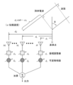
アレーアンテナを構成するためのアンテナ素子の配列法は、直線状、平面状、曲面状などの種々の配列が考えられるが、ここでは基本原理を理解するために、図8に示すようなK個の同一アンテナ素子からなるリニア(直線状)アレーを考える。
電波がブロードサイドから測って角度θの方向から1波到来したとする。ベースライン上の基準点での到来信号をE0と表し、アンテナ素子の指向性関数をg(θ)、アレーに対して到来信号が狭帯域であるとすると、k番目のアンテナ素子に誘起する電圧は式(1)で与えられる。



となる。
となる。
ここに、Ak,δkはそれぞれk番目の素子に掛けられる重みと移相量である。またD(θ)はアレーファクタである。式(2)のように、アレー全体の指向性は素子の指向性g(θ)とアレーファクタD(θ)との積で表される。これは指向性相乗の理(pattern multiplication)と呼ばれる。従って、全てのアンテナ素子が同一で同じ向きに置かれている場合は、アレーファクタを制御することで効果的にアレー全体の指向性の調整ができる。
例えば、ある角度θ0方向にアレーファクタの大きさを最大にしたい場合は、一般に移相量δkを

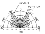
と選ぶ。即ち、所望信号に関して移相器の出力での位相が各素子にわたって揃うように定められる。それ以外の方向では、各素子の出力の位相が一致せず、互いにある程度の相殺が行われる。このようにして、アレーアンテナを用いると、所望信号に対する利得が上がる。ただし、素子間隔が大きい場合には、

を満足するような角度θgmでも同相になって加算されるので、大きなアレー応答値を生ずる。これはグレーティングローブ(grating lobe)と呼ばれ(図9B参照)、設計の段階で防止策がとられるのが普通である。式(2)の絶対値|Esum|を角度θの関数として表したものは指向性パターンと呼ばれ、その最大値周辺をメインローブ(メインビーム)と呼ぶ(図9A、B参照)。その他にも局所的に極大値がいくつも存在するが、これらはサイドローブと呼ばれる。また、ローブとローブの間の零点をヌル(null)という。
と選ぶ。即ち、所望信号に関して移相器の出力での位相が各素子にわたって揃うように定められる。それ以外の方向では、各素子の出力の位相が一致せず、互いにある程度の相殺が行われる。このようにして、アレーアンテナを用いると、所望信号に対する利得が上がる。ただし、素子間隔が大きい場合には、
を満足するような角度θgmでも同相になって加算されるので、大きなアレー応答値を生ずる。これはグレーティングローブ(grating lobe)と呼ばれ(図9B参照)、設計の段階で防止策がとられるのが普通である。式(2)の絶対値|Esum|を角度θの関数として表したものは指向性パターンと呼ばれ、その最大値周辺をメインローブ(メインビーム)と呼ぶ(図9A、B参照)。その他にも局所的に極大値がいくつも存在するが、これらはサイドローブと呼ばれる。また、ローブとローブの間の零点をヌル(null)という。
サイドローブ方向に不要波源が存在した場合には、それ相当の受信電圧が誘起される。もし、不要波と所望信号との電界強度比がサイドローブとメインローブの比の逆数よりも大きければ、アンテナ系の出力端においてすら、信号が不要波よりも劣勢になる。
アンテナ素子が等間隔に配置されているときには、式(3)のアレーファクタは整次多項式の形となるので、数学的な手段を利用してAkを適切に選んで、サイドローブを全般的に低くしたり、或いは特定の強力な不要波に対して、その到来方向の応答値を零にしたりすることが可能である。
しかし、その到来方向が未知であったり、または変化したりする場合には、何らかの学習を行って得られた情報をフィードバックし、最適の特性を作り上げることが必要になる。このような思想に基づくシステムがアダプティブ(適応型)アレーである。
(中継方法)
次に、図4及び図5を参照して、第1実施形態に係る中継装置の中継方法について説明する。図4は、第1実施形態に係る中継装置の中継方法のフローチャートである。図5は、アクセス無線の稼働による振幅及び位相の測定不具合の説明図である。
次に、図4及び図5を参照して、第1実施形態に係る中継装置の中継方法について説明する。図4は、第1実施形態に係る中継装置の中継方法のフローチャートである。図5は、アクセス無線の稼働による振幅及び位相の測定不具合の説明図である。
前述したように、ドナー基地局30からリレーノード22への無線通信(下りリンクDn)と、リレーノード22からドナー基地局30への無線通信(上りリンクUp)とは、同じ伝搬経路を経由することが判っている。
本実施形態では、下りリンクDnの無線通信の振幅及び位相を測定し、当該下りリンクDnと同振幅及び逆位相を上りリンクUpについても利用することで、より高い合成受信品質で無線通信を行うこととする。
その際、図5に示すように、中継装置20のアクセスノード24のアクセス無線が稼働している場合に、リレーノード22において下りリンクDnの無線通信の振幅及び位相を測定しながら上りリンクUpのためのアンテナの組み合わせを調整しようとすると、近距離で行われているアクセスノード24のアクセス無線からの高調波が干渉Ifしてしまう。したがって、下りリンクDnの無線通信の振幅及び位相測定が正しく行えず、上りリンクUpのビームフォーミングが的確に行えない。
そこで、第1実施形態では、中継装置20に端末装置10が在圏していないと推測される時間帯にタイマー27を起動し、所定の起動時間に端末装置10の在圏していないことを検出したらアクセス無線を停止し、ビームフォーミングを実行するように動作する。
具体的に、図4に示すように、まず、中継装置20に備えられたタイマー27の起動時刻は、当該中継装置20に端末装置10が在圏していないと推測される時間帯に設定される(ST21)。当該時間帯は、日常的に端末装置10が使用されないような時間帯、例えば深夜の時間帯を一律に設定することができる。また、中継装置20が公共の場所ではなく個人宅に設定される場合など、中継装置20に対して在圏しうる端末装置10が特定のもの限定可能な場合、この特定の端末装置10が利用される時間帯を計測等により予め設定しておき、当該特定の端末装置10が利用される可能性の最も低い時間帯にタイマー27の起動時間を設定してもよい。
タイマー27の設定時刻が経過、端末装置10の在圏していないことを検出し(ST22:NO)、アクセス無線を停止するまでは、振幅及び位相測定部25による振幅及び位相の測定は行われない。
タイマー27の設定時刻が経過し、かつ、端末装置10の在圏していないことを検出したら(ST22:YES)、アクセス無線が停止される(ST23)。次いで、振幅及び位相測定部25による振幅及び位相の測定が開始される(ST24)。振幅及び位相測定部25は、ドナー基地局30からリレーノード22への下りリンクDnの振幅及び位相を測定する。ビーム調整部28は、この下りリンクDnの振幅及び位相を測定し、当該下りリンクDnと同振幅及び逆位相となるように、複数のアンテナ素子からの上りリンクUpを調整する(ST25)。その後、アクセス無線を再稼働する(ST26)。
リレーノード22は、複数のアンテナからの振幅及び位相を調整することにより(ST25)、ドナー基地局30に対する上りリンクUpのビームを整形して集中させて強い電波で送って、ビームフォーミングを的確に行うことができる(ST27)。
以上説明したように、第1実施形態に係る中継装置20及びその中継方法によれば、タイマーの時刻設定により、端末装置10が在圏しない時間帯に端末装置10の在圏していないことを検出、アクセス無線を停止し、振幅及び位相測定部25がドナー基地局30からリレーノード22への下りリンクDnの振幅及び位相を測定するので、当該下りリンクDnの振幅及び位相が正しく測定される。したがって、アクセス無線からの高調波の影響を受けることなく、リレーノード22からドナー基地局30への上りリンクUpのビームフォーミングを的確に行うことができる。
[第2実施形態]
次に、第2実施形態に係る中継装置の構成について説明する。第1実施形態では、ビームフォーミングをタイマーによる設定に基づき実行していたが、当該第2実施形態は、タイマーに依らず一定期間端末装置10の在圏していないことを検出してビームフォーミングの実行の可否を判断する点で、第1実施形態と異なる。
次に、第2実施形態に係る中継装置の構成について説明する。第1実施形態では、ビームフォーミングをタイマーによる設定に基づき実行していたが、当該第2実施形態は、タイマーに依らず一定期間端末装置10の在圏していないことを検出してビームフォーミングの実行の可否を判断する点で、第1実施形態と異なる。
図6は、第2実施形態に係る中継装置のブロック図である。なお、図6において、第1実施形態と同様の構成要素については、同一の符号を付している。図6に示すように、第2実施形態に係るリレーノード22bは、タイマーを備えず、一定期間中継装置20への端末装置10の在圏のないことを検出する検出部26bを備える点で、第1実施形態と異なる。振幅及び位相測定部25とビーム調整部28については、第1実施形態と同様に動作する。
次に、第2実施形態に係る中継装置の中継方法について説明する。図7は、第2実施形態に係る中継装置の中継方法のフローチャートである。
図7に示すように、検出部26bは、一定期間中継装置20に端末装置10が在圏していないことを検出する(ST31)。一定時間端末装置10が在圏していなかったということは、端末装置10が周辺に存在しない、または、端末装置10のユーザが操作不能な状況にいるということが推測される。端末装置10が在圏していないことを検出したら(ST31:YES)、アクセスノード24においてアクセス無線を停止する(ST32)。
一方、中継装置20に端末装置10が在圏している間は(ST31:NO)、アクセス無線を停止せず振幅及び位相測定部25による振幅及び位相の測定は行われない。
アクセス無線の停止後、振幅及び位相測定部25による振幅及び位相の測定が開始される(ST33)。振幅及び位相測定部25は、ドナー基地局30からリレーノード22への下りリンクDnの振幅及び位相を測定する。この下りリンクDnの振幅及び位相を測定し、ビーム調整部28は、当該下りリンクDnと同振幅及び逆位相となるように、複数のアンテナ素子からの上りリンクUpを調整する(ST34)。その後、アクセス無線を再稼働する(ST35)。
リレーノード22は、複数のアンテナからの振幅及び位相を調整したので(ST34)、ドナー基地局30に対して上りリンクUpのビームを整形して集中させて強い電波で送り、ビームフォーミングを的確に行うことができる(ST36)。
以上説明したように、第2実施形態に係る中継装置20及びその中継方法によれば、検出部26bによって中継装置20に一定期間端末装置10が在圏していないと検出しアクセス無線を停止した場合に、振幅及び位相測定部25がドナー基地局30からリレーノード22への下りリンクDnの振幅及び位相を測定するので、下りリンクDnの無線通信にアクセス無線による高調波が干渉することが防止される。したがって、リレーノード22からドナー基地局30への上りリンクUpのビームフォーミングを的確に行うことができる。
以上説明した実施形態は、本発明の理解を容易にするためのものであり、本発明を限定して解釈するためのものではない。実施形態が備える各要素並びにその配置、材料、条件、形状及びサイズ等は、例示したものに限定されるわけではなく適宜変更することができる。また、異なる実施形態で示した構成同士を部分的に置換し又は組み合わせることが可能である。
例えば、上記の実施形態における中継装置20は、リレーノード22とアクセスノード24とを分離した分離型装置を例示して説明したが、リレーノード22とアクセスノード24を統合した一体型装置であっても構わない。分離型装置の場合、1基のリレーノードに対して、アクセスノードが複数の設けられることもある。
上記実施形態では、移動体通信に関する通信規格としてLTEを採用しているシステムについて説明した。しかし、本発明は、本発明と同様の課題を有する他のシステムにも適用可能である。すなわち、ドナー基地局と端末装置との間の通信を中継する中継装置にてアクセス無線の稼働中にビームフォーミングを実行しようとすると、近距離で行われているアクセス無線における無線通信において発生する高調波がバックホール無線における無線通信へ干渉してしまうという問題が生じるシステムであれば、本発明を適用可能である。本発明に係る中継方法を適用することによって、中継装置からドナー基地局へのビームフォーミングが的確に行えるという作用効果が期待できる。
10…端末装置、20…中継装置、22、22b…リレーノード、24…アクセスノード、30…ドナー基地局、100…無線ネットワーク
Claims (8)
- 端末装置とドナー基地局との間で通信を中継する中継装置であって、
前記ドナー基地局から前記中継装置への無線通信の振幅及び位相を測定する振幅及び位相測定部と、
測定された前記振幅及び位相に基づいて前記中継装置で使用する複数のアンテナからの振幅及び位相を調整して前記ドナー基地局に対してビームフォーミングのための調整を行うビーム調整部と、
を備え、
前記中継装置に対して前記端末装置が在圏していない時間帯に前記振幅及び位相を測定し、前記ドナー基地局に対してビームフォーミングのための調整を行う、中継装置。 - 前記中継装置は前記振幅及び位相測定部及び前記ビーム調整部を起動させるためのタイマーを備え、該タイマーは前記中継装置に対して前記端末装置が在圏していないと推測される時間帯に起動設定される、請求項1に記載の中継装置。
- 前記中継装置は、前記タイマーの起動後に、前記端末装置が在圏していないことを検出し、前記中継装置と端末装置との間のアクセス無線を停止してから前記振幅及び位相を測定する、請求項2に記載の中継装置。
- 前記中継装置は、前記端末装置の在圏の有無を検出する検出部を備え、該検出部が前記中継装置に対して一定期間前記端末装置の在圏がないことを検出した場合に、前記振幅及び位相を測定し、前記ドナー基地局に対してビームフォーミングための調整を行う、請求項1に記載の中継装置。
- 前記中継装置は、一定期間前記端末装置が在圏していないことを検出後、前記中継装置と端末装置との間のアクセス無線を停止してから前記振幅及び位相を測定する、請求項4に記載の中継装置。
- 前記中継装置は、前記ビームフォーミングのための調整を行った後、前記アクセス無線を再稼働する、請求項3に記載の中継装置。
- 前記中継装置は、前記ビームフォーミングのための調整を行った後、前記アクセス無線を再稼働する、請求項5に記載の中継装置。
- ドナー基地局から中継装置への無線通信の振幅及び位相を測定する工程と、
測定した振幅及び位相に基づいて、前記中継装置で使用する複数のアンテナからの振幅及び位相を調整して、前記中継装置から前記ドナー基地局への無線通信のビームフォーミングのための調整を行うビーム調整工程と、
を含み、
前記中継装置に対して前記端末装置が在圏していない時間帯に、前記振幅及び位相を測定してビームフォーミングのための調整を行う中継装置の中継方法。
Priority Applications (1)
| Application Number | Priority Date | Filing Date | Title |
|---|---|---|---|
| US15/506,720 US10484077B2 (en) | 2016-10-20 | 2016-12-14 | Relay apparatus and its relay method |
Applications Claiming Priority (2)
| Application Number | Priority Date | Filing Date | Title |
|---|---|---|---|
| JP2016-206129 | 2016-10-20 | ||
| JP2016206129A JP6294937B1 (ja) | 2016-10-20 | 2016-10-20 | 中継装置及びその中継方法 |
Publications (1)
| Publication Number | Publication Date |
|---|---|
| WO2018073982A1 true WO2018073982A1 (ja) | 2018-04-26 |
Family
ID=61629010
Family Applications (1)
| Application Number | Title | Priority Date | Filing Date |
|---|---|---|---|
| PCT/JP2016/087214 Ceased WO2018073982A1 (ja) | 2016-10-20 | 2016-12-14 | 中継装置及びその中継方法 |
Country Status (3)
| Country | Link |
|---|---|
| US (1) | US10484077B2 (ja) |
| JP (1) | JP6294937B1 (ja) |
| WO (1) | WO2018073982A1 (ja) |
Families Citing this family (1)
| Publication number | Priority date | Publication date | Assignee | Title |
|---|---|---|---|---|
| KR102657422B1 (ko) * | 2019-09-03 | 2024-04-16 | 삼성전자 주식회사 | 댁내 중계 장치 및 그와 연결되는 전자 장치 |
Citations (5)
| Publication number | Priority date | Publication date | Assignee | Title |
|---|---|---|---|---|
| WO2008111142A1 (ja) * | 2007-03-09 | 2008-09-18 | Fujitsu Limited | 無線局 |
| WO2014126161A1 (ja) * | 2013-02-14 | 2014-08-21 | ハイウェーブ, インコ-ポレイティド | アンテナ制御方法及びアンテナ制御システム |
| JP2015507900A (ja) * | 2012-01-19 | 2015-03-12 | テレフオンアクチーボラゲット エル エム エリクソン(パブル) | ヘテロジーニアスネットワークのリレーノードにおける部分的な(fractional)周波数の再利用及びビームフォーミング |
| JP2015091121A (ja) * | 2013-11-06 | 2015-05-11 | エアーポイント カンパニー リミテッド | 無線中継システム及びその動作方法 |
| JP2015534782A (ja) * | 2012-10-05 | 2015-12-03 | テレフオンアクチーボラゲット エル エム エリクソン(パブル) | モバイルリレーノードからヘテロジーニアスネットワークへの干渉の軽減 |
Family Cites Families (3)
| Publication number | Priority date | Publication date | Assignee | Title |
|---|---|---|---|---|
| GB2479377B (en) * | 2010-04-07 | 2013-08-14 | Toshiba Res Europ Ltd | Dual indicator scheme for channel state information feedback |
| US8805394B2 (en) | 2012-05-17 | 2014-08-12 | Intel Corporation | Systems and methods for interference mitigation in heterogeneous networks |
| KR101504041B1 (ko) * | 2013-02-14 | 2015-03-18 | 하이웨이브 주식회사 | 안테나 제어 방법 및 이를 실행하는 시스템 |
-
2016
- 2016-10-20 JP JP2016206129A patent/JP6294937B1/ja not_active Expired - Fee Related
- 2016-12-14 US US15/506,720 patent/US10484077B2/en not_active Expired - Fee Related
- 2016-12-14 WO PCT/JP2016/087214 patent/WO2018073982A1/ja not_active Ceased
Patent Citations (5)
| Publication number | Priority date | Publication date | Assignee | Title |
|---|---|---|---|---|
| WO2008111142A1 (ja) * | 2007-03-09 | 2008-09-18 | Fujitsu Limited | 無線局 |
| JP2015507900A (ja) * | 2012-01-19 | 2015-03-12 | テレフオンアクチーボラゲット エル エム エリクソン(パブル) | ヘテロジーニアスネットワークのリレーノードにおける部分的な(fractional)周波数の再利用及びビームフォーミング |
| JP2015534782A (ja) * | 2012-10-05 | 2015-12-03 | テレフオンアクチーボラゲット エル エム エリクソン(パブル) | モバイルリレーノードからヘテロジーニアスネットワークへの干渉の軽減 |
| WO2014126161A1 (ja) * | 2013-02-14 | 2014-08-21 | ハイウェーブ, インコ-ポレイティド | アンテナ制御方法及びアンテナ制御システム |
| JP2015091121A (ja) * | 2013-11-06 | 2015-05-11 | エアーポイント カンパニー リミテッド | 無線中継システム及びその動作方法 |
Also Published As
| Publication number | Publication date |
|---|---|
| JP6294937B1 (ja) | 2018-03-14 |
| US20190089449A1 (en) | 2019-03-21 |
| US10484077B2 (en) | 2019-11-19 |
| JP2018067843A (ja) | 2018-04-26 |
Similar Documents
| Publication | Publication Date | Title |
|---|---|---|
| US11012136B2 (en) | Beamforming in a MU-MIMO wireless communication system with relays | |
| JP6548853B1 (ja) | 無線中継装置および無線通信システム | |
| Witvliet et al. | Near vertical incidence skywave propagation: Elevation angles and optimum antenna height for horizontal dipole antennas | |
| CN103931112B (zh) | 用于在波束形成无线通信系统中进行波束选择的装置和方法 | |
| US9252864B2 (en) | Method and apparatus for fast beam-link construction in mobile communication system | |
| US20110032849A1 (en) | Systems and methods for mitigating interference between access points | |
| US20110222616A1 (en) | MIMO Transmission with Rank Adaptation for Multi-Gigabit 60 GHz Wireless | |
| US20120299765A1 (en) | Compact smart antenna for mobile wireless communications | |
| JP6379152B2 (ja) | 中継装置及びその中継方法 | |
| CN113228533B (zh) | 通信网络和进行连接的方法 | |
| US20240235635A1 (en) | Reconfigurable device influencing radio wave spatial properties | |
| CN112585881B (zh) | 通信设备中的多波束接收 | |
| Alexandropoulos et al. | Smart wireless environments enabled by RISs: Deployment scenarios and two key challenges | |
| US20240171221A1 (en) | Filter management procedure for reconfigurable relaying devices using polarization multiplexing of data signals and reference signals | |
| JP5923921B2 (ja) | 無線リレー局のアンテナ制御方法、無線リレー局 | |
| Roberts et al. | Millimeter wave analog beamforming codebooks robust to self-interference | |
| JP6294937B1 (ja) | 中継装置及びその中継方法 | |
| CN103067066A (zh) | 双天线卫星通信系统下行链路干扰抑制方法 | |
| CN121713406A (zh) | 用于联合相位时间阵列的3d波束成形 | |
| CN106025500B (zh) | 利用解耦网络的多重天线 | |
| US8588817B2 (en) | Wireless communication device and method | |
| JP7698595B2 (ja) | ビームを高精度に形成して通信する通信装置、制御装置、制御方法、及びプログラム | |
| US20240429996A1 (en) | Filter management for wide output beams at coverage enhancing devices | |
| Krasikov et al. | Research of the satellite transponder beams interference impact | |
| US20250141498A1 (en) | Device and method for updating ris beam |
Legal Events
| Date | Code | Title | Description |
|---|---|---|---|
| 121 | Ep: the epo has been informed by wipo that ep was designated in this application |
Ref document number: 16919097 Country of ref document: EP Kind code of ref document: A1 |
|
| NENP | Non-entry into the national phase |
Ref country code: DE |
|
| 122 | Ep: pct application non-entry in european phase |
Ref document number: 16919097 Country of ref document: EP Kind code of ref document: A1 |