WO2018070360A1 - 揮発性有機物検知体及びその製造方法、揮発性有機物の検知方法並びに揮発性有機物検知装置 - Google Patents
揮発性有機物検知体及びその製造方法、揮発性有機物の検知方法並びに揮発性有機物検知装置 Download PDFInfo
- Publication number
- WO2018070360A1 WO2018070360A1 PCT/JP2017/036572 JP2017036572W WO2018070360A1 WO 2018070360 A1 WO2018070360 A1 WO 2018070360A1 JP 2017036572 W JP2017036572 W JP 2017036572W WO 2018070360 A1 WO2018070360 A1 WO 2018070360A1
- Authority
- WO
- WIPO (PCT)
- Prior art keywords
- volatile organic
- organic substance
- detector
- substance detector
- substance detection
- Prior art date
- Legal status (The legal status is an assumption and is not a legal conclusion. Google has not performed a legal analysis and makes no representation as to the accuracy of the status listed.)
- Ceased
Links
- 0 *c1c(*)c(*)c(*)c(*)c1* Chemical compound *c1c(*)c(*)c(*)c(*)c1* 0.000 description 1
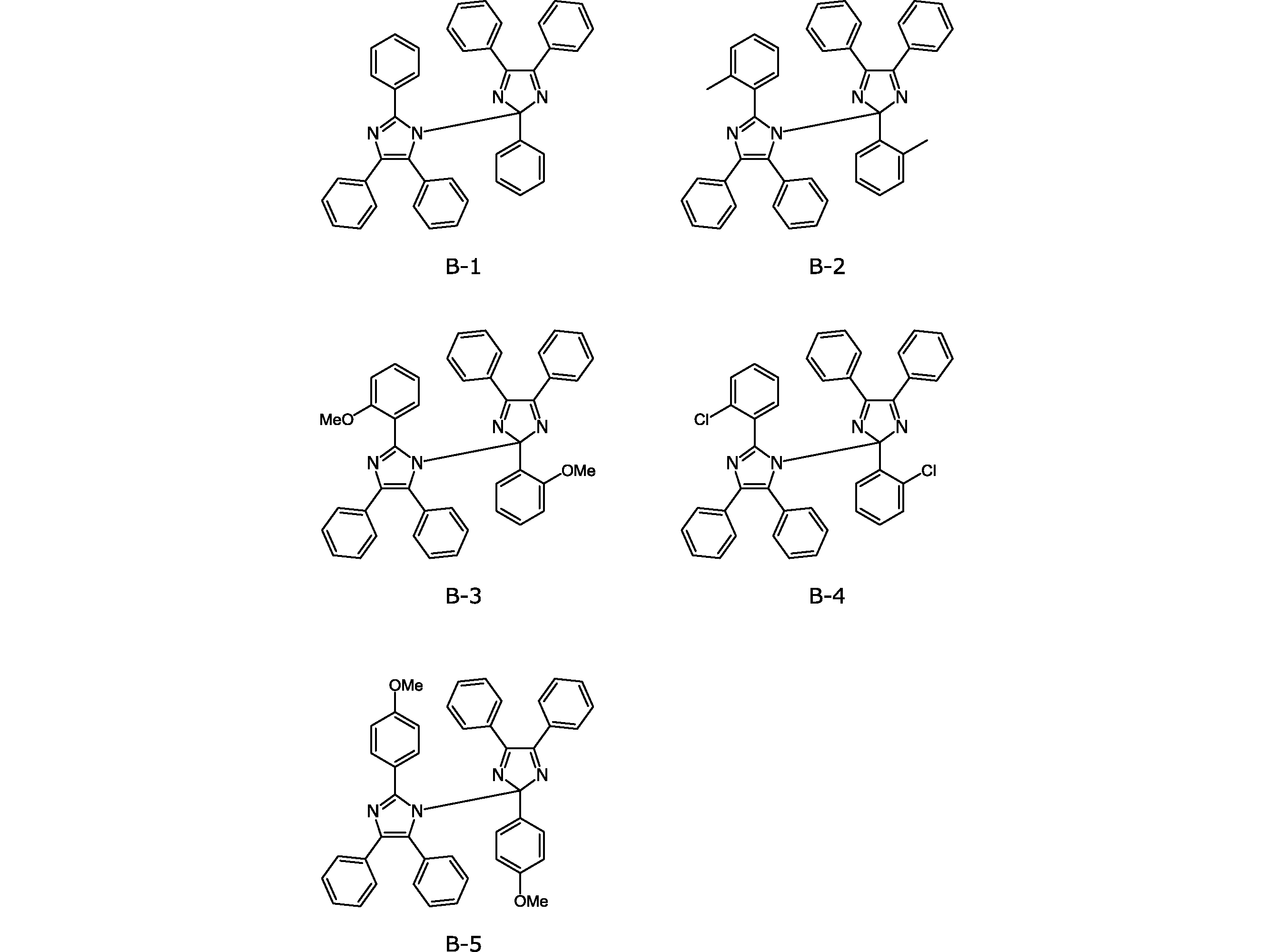
- XOKSPSAYQLPGBI-UHFFFAOYSA-N COc1ccc(C([n]2c(-c(cc3)ccc3OC)nc(-c3ccccc3)c2-c2ccccc2)(N=C2c3ccccc3)N=C2c2ccccc2)cc1 Chemical compound COc1ccc(C([n]2c(-c(cc3)ccc3OC)nc(-c3ccccc3)c2-c2ccccc2)(N=C2c3ccccc3)N=C2c2ccccc2)cc1 XOKSPSAYQLPGBI-UHFFFAOYSA-N 0.000 description 1
- VYQXQPVJLFTJQI-UHFFFAOYSA-N COc1ccccc1C([n]1c(-c(cccc2)c2OC)nc(-c2ccccc2)c1-c1ccccc1)(N=C1c2ccccc2)N=C1c1ccccc1 Chemical compound COc1ccccc1C([n]1c(-c(cccc2)c2OC)nc(-c2ccccc2)c1-c1ccccc1)(N=C1c2ccccc2)N=C1c1ccccc1 VYQXQPVJLFTJQI-UHFFFAOYSA-N 0.000 description 1
- WSZWUSHWRSORQG-UHFFFAOYSA-N Cc1c(C([n]2c(-c3c(C)cccc3)nc(-c3ccccc3)c2-c2ccccc2)(N=C2c3ccccc3)N=C2c2ccccc2)cccc1 Chemical compound Cc1c(C([n]2c(-c3c(C)cccc3)nc(-c3ccccc3)c2-c2ccccc2)(N=C2c3ccccc3)N=C2c2ccccc2)cccc1 WSZWUSHWRSORQG-UHFFFAOYSA-N 0.000 description 1
- MHDULSOPQSUKBQ-UHFFFAOYSA-N Clc1ccccc1C([n]1c(-c(cccc2)c2Cl)nc(-c2ccccc2)c1-c1ccccc1)(N=C1c2ccccc2)N=C1c1ccccc1 Chemical compound Clc1ccccc1C([n]1c(-c(cccc2)c2Cl)nc(-c2ccccc2)c1-c1ccccc1)(N=C1c2ccccc2)N=C1c1ccccc1 MHDULSOPQSUKBQ-UHFFFAOYSA-N 0.000 description 1
- GMIUUCWUOPOETN-UHFFFAOYSA-N c1ccc(C([n]2c(-c3ccccc3)nc(-c3ccccc3)c2-c2ccccc2)(N=C2c3ccccc3)N=C2c2ccccc2)cc1 Chemical compound c1ccc(C([n]2c(-c3ccccc3)nc(-c3ccccc3)c2-c2ccccc2)(N=C2c3ccccc3)N=C2c2ccccc2)cc1 GMIUUCWUOPOETN-UHFFFAOYSA-N 0.000 description 1
Images

Classifications
-
- C—CHEMISTRY; METALLURGY
- C07—ORGANIC CHEMISTRY
- C07D—HETEROCYCLIC COMPOUNDS
- C07D231/00—Heterocyclic compounds containing 1,2-diazole or hydrogenated 1,2-diazole rings
- C07D231/02—Heterocyclic compounds containing 1,2-diazole or hydrogenated 1,2-diazole rings not condensed with other rings
- C07D231/10—Heterocyclic compounds containing 1,2-diazole or hydrogenated 1,2-diazole rings not condensed with other rings having two or three double bonds between ring members or between ring members and non-ring members
- C07D231/14—Heterocyclic compounds containing 1,2-diazole or hydrogenated 1,2-diazole rings not condensed with other rings having two or three double bonds between ring members or between ring members and non-ring members with hetero atoms or with carbon atoms having three bonds to hetero atoms with at the most one bond to halogen, e.g. ester or nitrile radicals, directly attached to ring carbon atoms
- C07D231/38—Nitrogen atoms
-
- G—PHYSICS
- G01—MEASURING; TESTING
- G01N—INVESTIGATING OR ANALYSING MATERIALS BY DETERMINING THEIR CHEMICAL OR PHYSICAL PROPERTIES
- G01N21/00—Investigating or analysing materials by the use of optical means, i.e. using sub-millimetre waves, infrared, visible or ultraviolet light
- G01N21/75—Systems in which material is subjected to a chemical reaction, the progress or the result of the reaction being investigated
- G01N21/77—Systems in which material is subjected to a chemical reaction, the progress or the result of the reaction being investigated by observing the effect on a chemical indicator
- G01N21/78—Systems in which material is subjected to a chemical reaction, the progress or the result of the reaction being investigated by observing the effect on a chemical indicator producing a change of colour
-
- G—PHYSICS
- G01—MEASURING; TESTING
- G01N—INVESTIGATING OR ANALYSING MATERIALS BY DETERMINING THEIR CHEMICAL OR PHYSICAL PROPERTIES
- G01N31/00—Investigating or analysing non-biological materials by the use of the chemical methods specified in the subgroup; Apparatus specially adapted for such methods
-
- G—PHYSICS
- G01—MEASURING; TESTING
- G01N—INVESTIGATING OR ANALYSING MATERIALS BY DETERMINING THEIR CHEMICAL OR PHYSICAL PROPERTIES
- G01N31/00—Investigating or analysing non-biological materials by the use of the chemical methods specified in the subgroup; Apparatus specially adapted for such methods
- G01N31/22—Investigating or analysing non-biological materials by the use of the chemical methods specified in the subgroup; Apparatus specially adapted for such methods using chemical indicators
Definitions
- the present invention relates to a volatile organic substance detector and a method for producing the same, a volatile organic substance detection method, and a volatile organic substance detector.
- VOC volatile organic compound
- Patent Document 1 Although the use of an organic-inorganic hybrid membrane has also been studied to increase selectivity (Patent Document 1), the problem that the operating temperature is high and takes time to stabilize has not been solved.
- the present invention has been made in view of such circumstances, and has a high selectivity, a low operating temperature, and a short time until stabilization, a volatile organic substance detector, a method for producing the same, and detection of volatile organic substances. It is an object to provide a method and a volatile organic substance detection device.
- a volatile organic substance detector includes a base and a hexaarylbisimidazole represented by the following general formula (1), which is included in the base.
- R 1 to R 30 each independently represents a hydrogen atom or a substituent.
- the method for producing a volatile organic substance detector includes a step of impregnating the hexaarylbisimidazole represented by the general formula (1) and a step of drying the substrate.
- the method for detecting a volatile organic substance includes a step of irradiating the above-described volatile organic substance detector with an electromagnetic wave to color the volatile organic substance detector, and detecting a decoloration of the volatile organic substance detector based on the presence of the volatile organic substance. And a step of performing.
- the volatile organic substance detection device includes the above-described volatile organic substance detector, a coloring means for irradiating the volatile organic substance detector with electromagnetic waves and coloring, and a volatile organic substance based on the presence of the volatile organic substance.
- a decoloring detecting means for detecting decoloring of the detection body.
- a volatile organic substance detector a method for manufacturing the same, a volatile organic substance detection method, and a volatile organic substance detector, which have high selectivity, low operating temperature, and short time for stabilization. be able to.
- the volatile organic substance detector according to the present embodiment includes a base and hexaarylbisimidazole (HABI) represented by the general formula (1) included in the base.
- HABI hexaarylbisimidazole
- R 1 to R 30 each independently represents a hydrogen atom or a substituent.
- the substrate is an absorbent substrate capable of absorbing HABI inside.
- the substrate is preferably a substrate containing cellulose, and more preferably a substrate such as paper mainly composed of cellulose.
- the cellulose content in the substrate is 80% or more, preferably 90% or more.
- Hexaarylbisimidazole is represented by the above general formula (1), and in the general formula (1), R 1 to R 30 each independently represents a hydrogen atom or a substituent.
- FIG. 1 is a diagram for explaining the operation of the volatile organic substance detector according to the present embodiment.
- HABI is dispersed in a substrate such as cellulose.
- HABI shows a photochromism in which the CN bond connecting two imidazole rings is equally cleaved by irradiation with electromagnetic waves such as ultraviolet light, and a triphenylimidazolyl radical (TPIR: lophyll radical) as a color former is generated. Color develops.
- TPIR triphenylimidazolyl radical
- the inventor of the present application has found that a reaction (radical recombination) from TPIR to HABI occurs and discolors in an atmosphere in which a specific organic vapor exists. This is presumed that certain organic vapors accelerate TPIR motion and promote recombination. For this reason, it discovered that the base
- the color retention period can be extended by impregnating and dispersing HABI in a substrate such as cellulose.
- a substrate such as cellulose.
- the return reaction of TPIR can be effectively suppressed by using a substrate containing cellulose as the substrate. For this reason, it is suppressed that it returns to the original structure gradually in the presence of factors other than organic substances, for example, heat at room temperature or visible light, and fading.
- the volatile organic substance detector can be returned to the initial state by heating at 50 ° C. or higher.
- the above-mentioned volatile organic substance detector using HABI has a low operating temperature and does not have to wait for stabilization. It does not react at all with hexane, ammonia and alcohol vapors, but reacts with other organic solvent (acetone, ethyl acetate, tetrahydrofuran, etc.) vapors and immediately disappears. This has a selectivity not found in the semiconductor type sensors. Moreover, since it can return to an initial state by heating, it can be used any number of times.
- At least one of R 1 to R 30 is a substituent selected from a fluorine atom, a fluorinated alkyl group, or a cyano group.
- a substituent selected from a fluorine atom, a fluorinated alkyl group, or a cyano group By introducing such an electron-withdrawing substituent, the return (radical recombination) reaction from TPIR to HABI can be suppressed, and fading can be significantly suppressed.
- a volatile organic matter detector having improved stability and repeated durability can be provided.
- At least one of R 1 to R 5 and R 16 to R 20 is a substituent selected from a fluorine atom, a fluorinated alkyl group, or a cyano group.
- the method for producing a volatile organic substance detector includes a step of impregnating a substrate with hexaarylbisimidazole (HABI) represented by the general formula (1) and a step of drying the substrate impregnated with HABI. And including.
- HABI hexaarylbisimidazole
- HABI hydroxyadiene styrene
- a substrate such as a cellulose substrate is impregnated with a solution in which HABI is dissolved in an organic solvent.
- the cellulose substrate may be immersed in a solution containing HABI, or a solution containing HABI may be applied to the cellulose substrate.
- the cellulose substrate impregnated with HABI is dried to produce a volatile organic substance detector.
- a method for detecting a volatile organic substance will be described. At least a part of the volatile organic substance detector impregnated with HABI is irradiated with an electromagnetic wave such as ultraviolet light. Thereby, HABI at the site irradiated with ultraviolet light is cleaved to become TPIR and colored. Then, the colored volatile organic substance detector is placed in a predetermined atmosphere. When the target volatile organic substance is contained in the atmosphere, the volatile organic substance detector is decolored, so the presence of the target volatile organic substance can be confirmed by detecting this decoloration. . By heating the volatile organic substance detector after measurement to 50 ° C. or higher, the volatile organic substance detector can be returned to the initial state. Thereby, a volatile organic matter detector can be used repeatedly.
- FIG. 2 is a diagram illustrating a schematic configuration of the volatile organic substance detection device according to the present embodiment.
- the volatile organic matter detection device 10 includes the volatile organic matter detector 1, the activation light source (coloring means) 2, the detection light source 3, the light receiving unit 4, the heating unit 5, and a housing that houses these. 6, a flow rate control unit 7 that controls the flow rate of the target gas 11 to the hole 6 a provided in the housing 6, a calculation unit 8, and a storage unit 9.
- storage part 9 are equivalent to the decoloring detection means of this invention.
- the activation light source 2 irradiates an electromagnetic wave composed of 200 to 450 nm ultraviolet light.
- an ultraviolet fluorescent tube central emission wavelength 254 nm
- the detection light source 3 emits detection light including visible light having a wavelength of 500 to 600 nm.
- a green LED emission wavelength: 505 to 555 nm
- the light receiving unit 4 is composed of a photodiode that detects the intensity of the detection light reflected from the volatile organic substance detector 1.
- the light receiving unit 4 may detect the intensity of the detection light that has passed (transmitted) through the volatile organic substance detector 1.
- the heating unit 5 is a heater for heating the volatile organic substance detector 1 after measurement.
- the volatile organic substance detector 1 is returned to the initial state by heating the volatile organic substance detector 1 to 50 ° C. or higher by the heating unit 5.
- the calculation unit 8 calculates the intensity (initial data) of the detection light from the volatile organic substance detector 1 before exposure to the target gas and the intensity (measurement) of the detection light from the volatile organic substance detector 1 after exposure to the target gas. Data) difference. If this difference is larger than a preset threshold value, it can be determined that the volatile organic substance detector 1 has been extinguished due to the presence of the organic substance, and it is determined that the target gas 11 contains a volatile organic substance.
- the storage unit 9 records initial data and measurement data of the light intensity detected by the light receiving unit 4.
- the detection light source 3 detects the detection light (visible light).
- the light receiving unit 4 detects the intensity of the detection light reflected from the volatile organic substance detector 1.
- the intensity of the detected detection light is stored in the storage unit 9.
- a predetermined amount of the target gas 11 is introduced into the housing 6 by the flow rate control unit 7, and then the detection light source 3 irradiates the detection light to the volatile organic substance detector 1 again and uses the light receiving unit 4 to detect the detection light.
- the intensity is detected, and the measurement data is stored in the storage unit 9.
- the computing unit 8 determines the extinction state of the volatile organic substance detector 1 from the difference between the initial data and the measurement data, and detects whether or not the target gas 11 contains a volatile organic substance. After the measurement is completed, the volatile organic substance detector 1 can be decolored by heating the volatile organic substance detector 1 with the heating unit 5, and the volatile organic substance detector 1 can be returned to the initial state before coloring. Therefore, the volatile organic matter detector 1 can be reused.
- Example 1 (exposure) The produced sample of Example 1 was exposed for 1 minute using a UV lamp (UVGL-25 Compact UV Lamp, manufactured by Funakoshi Co., Ltd.) to obtain a colored sample. In the same manner as the sample of Example 1, colored samples of Examples 2 to 8 were obtained.
- a UV lamp UVGL-25 Compact UV Lamp, manufactured by Funakoshi Co., Ltd.
- Example 1 (Comparative sample) A comparison was carried out in the same manner except that a solution a-7 containing Compound A-7 was prepared by dropping the solution into a film using a slide glass (S1214 manufactured by MATSANAMI) without using a filter paper as a support. A sample of Example 1 was prepared and subjected to the same exposure test. The results are shown in Table 2.
- Table 2 shows that the samples of Examples 1 to 8 can detect ethyl acetate.
- Table 3 shows that the detectable solvent and the undetectable solvent are clearly distinguished.
- Example of volatile organic substance detection device A model device of the volatile organic substance detection device shown in FIG. 2 was produced.
- a green LED emission wavelength 505 to 555 nm
- an ultraviolet fluorescent tube central emission wavelength 254 nm
- the green LED was caused to emit light, and the absorption intensity in the reflected light was measured with a photodiode (light receiving unit 4).
- the green LED was made to emit light again, and the absorption intensity in the reflected light was measured with a photodiode, which was 0.2. It was confirmed that the absorption intensity recovered to near 1 by heating to 100 ° C. with a heater and irradiating the ultraviolet fluorescent tube again.
- the volatile organic substance detector according to this embodiment includes a base and a hexaarylbisimidazole represented by the general formula (1) included in the base. Thereby, the selectivity of the volatile organic substance used as a detection target is high, the operating temperature is low, and the time until stabilization is short can be provided.
- the substrate contains cellulose. Thereby, the decoloring effect can be promoted.
- At least one of R 1 to R 30 is a substituent selected from a fluorine atom, a fluorinated alkyl group, or a cyano group.
- a substituent selected from a fluorine atom, a fluorinated alkyl group, or a cyano group is a substituent selected from a fluorine atom, a fluorinated alkyl group, or a cyano group.
- At least one of R 1 to R 5 and R 16 to R 20 is a substituent selected from a fluorine atom, a fluorinated alkyl group, or a cyano group.
- a substituent selected from a fluorine atom, a fluorinated alkyl group, or a cyano group is a substituent selected from a fluorine atom, a fluorinated alkyl group, or a cyano group.
- the method for producing a volatile organic substance detector according to the present embodiment includes a step of impregnating the base with the hexaarylbisimidazole represented by the general formula (1) and a step of drying the base. According to this embodiment, a volatile organic substance detector having the above-described performance can be manufactured at low cost.
- the method for detecting a volatile organic substance includes a step of irradiating the above-described volatile organic substance detector with an electromagnetic wave and coloring, and a step of detecting decoloration of the volatile organic substance detector based on the presence of the volatile organic substance. And including. Accordingly, it is possible to provide a method for detecting a volatile organic substance that has a high selectivity of a volatile organic substance to be detected, a low operating temperature, and a short time until stabilization.
- the volatile organic matter detector includes the above-described volatile organic matter detector, a coloring means for irradiating and coloring the volatile organic matter detector, and a volatile organic matter detector based on the presence of the volatile organic matter. And a decoloring detecting means for detecting the decoloring.
- the decoloring detection means includes a detection light source for irradiating the volatile organic substance detector with detection light having a wavelength of 500 to 600 nm, a detection light receiving unit for detecting the intensity of the detection light that has passed through or reflected from the volatile organic substance detector, and .
- a heating unit for heating the volatile organic substance detector is further provided. Thereby, after completion
- SYMBOLS 1 Volatile organic substance detection body, 2 ... Activation light source (coloring means), 3 ... Light source for detection, 4 ... Light receiving part, 5 ... Heating part, 6 ... Housing
Landscapes
- Chemical & Material Sciences (AREA)
- Life Sciences & Earth Sciences (AREA)
- Health & Medical Sciences (AREA)
- Physics & Mathematics (AREA)
- Pathology (AREA)
- Immunology (AREA)
- Organic Chemistry (AREA)
- Analytical Chemistry (AREA)
- Biochemistry (AREA)
- General Health & Medical Sciences (AREA)
- General Physics & Mathematics (AREA)
- Molecular Biology (AREA)
- Plasma & Fusion (AREA)
- Engineering & Computer Science (AREA)
- Biophysics (AREA)
- Chemical Kinetics & Catalysis (AREA)
- Investigating Or Analyzing Non-Biological Materials By The Use Of Chemical Means (AREA)
- Investigating Or Analysing Materials By The Use Of Chemical Reactions (AREA)
Abstract
選択性が高く、動作温度が低く、安定化するまでの時間が短い、揮発性有機物検知体及びその製造方法、揮発性有機物の検知方法並びに揮発性有機物検知装置を提供する。 本発明の一態様に係る揮発性有機物検知体は、基体と、前記基体に含まれる、下記一般式(1)で表されるヘキサアリールビスイミダゾールと、を備える。(一般式(1)中、R1~R30はそれぞれ独立に、水素原子又は置換基を表す。)
Description
本発明は、揮発性有機物検知体及びその製造方法、揮発性有機物の検知方法並びに揮発性有機物検知装置に関する。
揮発性有機化合物(VOC)検出方式として金属酸化物半導体を用いた抵抗変化による検出方式が広く使用されているが、動作温度が高いことによって、センサの電力消費量が大きい、センサに電源を入れてから安定に使えるまでに時間がかかる、という問題と、選択性が低いという問題があった。
選択性を上げるために有機無機ハイブリッド膜を用いることも検討されている(特許文献1)が、動作温度が高く、安定するまでに時間がかかるという問題は解決されていない。
本発明はこのような事情に鑑みてなされたものであり、選択性が高く、動作温度が低く、安定化するまでの時間が短い、揮発性有機物検知体及びその製造方法、揮発性有機物の検知方法並びに揮発性有機物検知装置を提供することを目的とする。
本発明の一態様に係る揮発性有機物検知体は、基体と、基体に含まれる、下記一般式(1)で表されるヘキサアリールビスイミダゾールと、を備える。
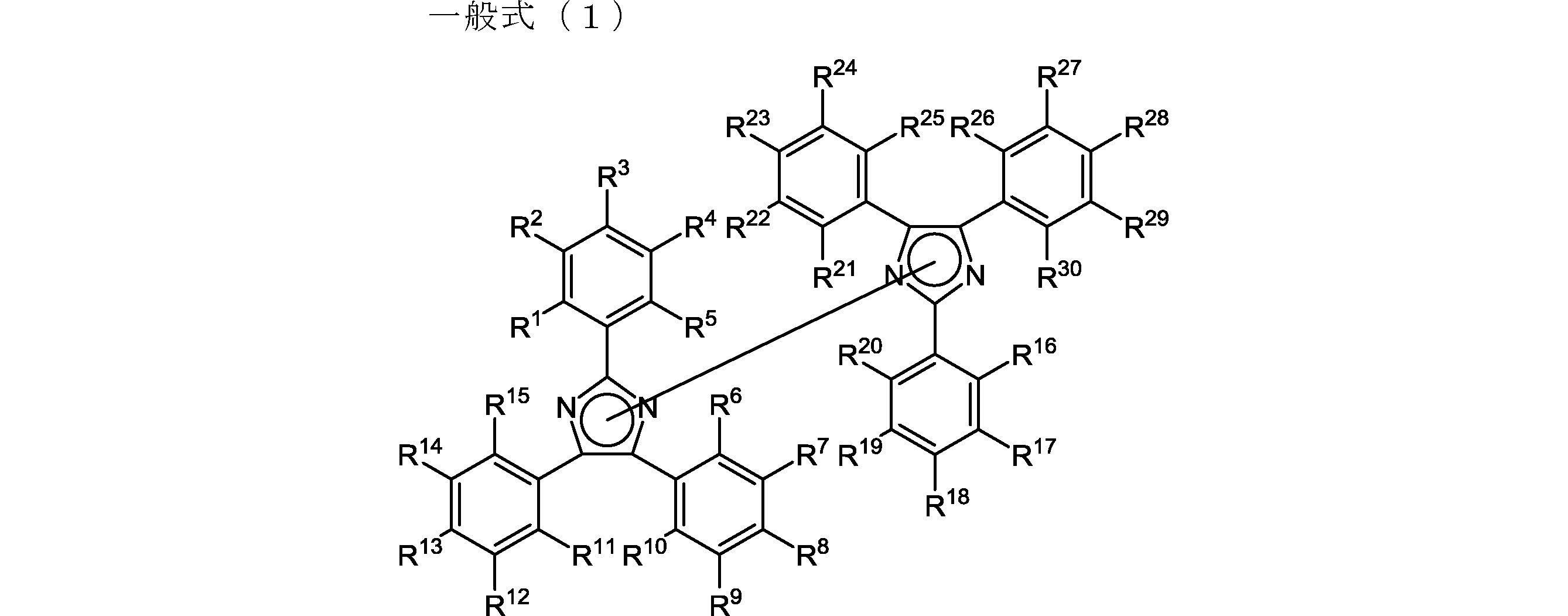
一般式(1)中、R1~R30はそれぞれ独立に、水素原子又は置換基を表す。
本発明の一態様に係る揮発性有機物検知体の製造方法は、上記一般式(1)で表されるヘキサアリールビスイミダゾールを含浸させる工程と、基体を乾燥させる工程と、を含む。
本発明の一態様に係る揮発性有機物の検知方法は、上述した揮発性有機物検知体に電磁波を照射して着色させる工程と、揮発性有機物の存在に基づく揮発性有機物検知体の消色を検知する工程と、を含む。
本発明の一態様に係る揮発性有機物検知装置は、上述した揮発性有機物検知体と、揮発性有機物検知体に電磁波を照射して着色させる着色手段と、揮発性有機物の存在に基づく揮発性有機物検知体の消色を検知する消色検知手段と、を備える。
本発明によれば、選択性が高く、動作温度が低く、安定化するまでの時間が短い、揮発性有機物検知体及びその製造方法、揮発性有機物の検知方法並びに揮発性有機物検知装置を提供することができる。
添付図面を参照して、本発明の好適な実施形態について説明する。(なお、各図において、同一の符号を付したものは、同一又は同様の構成を有する。)
本実施形態に係る揮発性有機物検知体は、基体と、基体に含まれる、一般式(1)で表されるヘキサアリールビスイミダゾール(HABI)と、を備える。
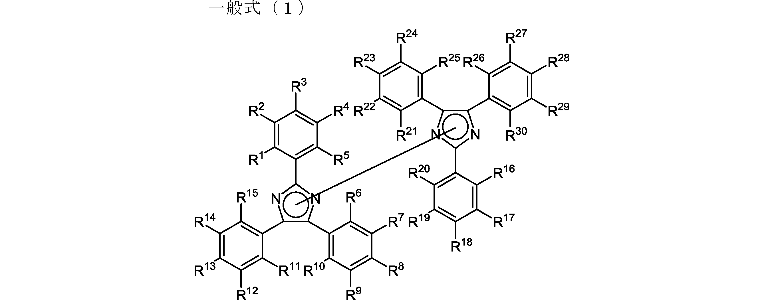
一般式(1)中、R1~R30はそれぞれ独立に、水素原子又は置換基を表す。
基体は、HABIを内部に吸収し得る吸収性基体である。基体は、好ましくは、セルロースを含む基体であり、さらに好ましくはセルロースを主成分とする紙などの基体である。基体におけるセルロースの含有率は80%以上であり、好ましくは90%以上である。
ヘキサアリールビスイミダゾール(HABI)は、上記一般式(1)で表されるものであり、一般式(1)中、R1~R30はそれぞれ独立に、水素原子、置換基を表す。
図1は、本実施形態に係る揮発性有機物検知体の作用を説明するための図である。
本実施形態では、HABIはセルロースなどの基体中に分散されている。HABIは、紫外光などの電磁波の照射により、二つのイミダゾール環を結ぶC-N結合が均等開裂し、発色体であるトリフェニルイミダゾリルラジカル(TPIR:ロフィルラジカル)を生成するフォトクロミズムを示し、その結果、発色する。
本願発明者は、特定の有機蒸気が存在する雰囲気下ではTPIRからHABIへの戻り(ラジカル再結合)反応が起こり消色することを発見した。これは、特定の有機蒸気がTPIRの運動を加速させ再結合を促すものと推定される。このため、HABIを含む基体が、揮発性有機物検知体として作用することを見出した。検出後、揮発性有機物検知体を加熱することにより、揮発性有機物検知体を完全に消色させ、かつ有機蒸気を揮発させ初期状態に戻すことができる。このため、揮発性有機物検知体の再利用が可能となる。
セルロースのような基体にHABIを含浸させ分散させることにより、色保持期間を長くすることができる。基体中にHABIを分散させることにより、HABIの運動を拘束して、戻り反応を起こし難くすることができる。特に、基体としてセルロースを含有する基体を使用することによりTPIRの戻り反応を効果的に抑制できる。このため、有機物以外の因子、例えば、室温程度の熱あるいは可視光の存在下で徐々に元の構造へ戻ってしまい退色することが抑制される。一方、50℃以上の加熱により、揮発性有機物検知体を初期状態に戻すことができる。
上述したHABIを利用した揮発性有機物検知体は、動作温度が低く、安定化まで待つ必要がない。そして、ヘキサンやアンモニア、アルコール蒸気に対しては全く反応せず、他の有機溶剤(アセトン、酢酸エチル、テトラヒドロフランなど)蒸気に対しては、即座に反応し消色する、というように、これまでの半導体式センサにはない選択性を有する。また、加熱によって初期状態に戻すことができるため、何度でも使用することができる。
好ましくは、一般式(1)中、R1~R30のいずれか少なくとも一つが、フッ素原子、フッ素化アルキル基又はシアノ基から選択される置換基である。このような電子吸引性置換基を導入することにより、TPIRからHABIへの戻り(ラジカル再結合)反応を抑制することができ、退色を大幅に抑制できる。これにより、HABIを利用した揮発性有機物検知体の中でも、安定性、繰り返し耐久性を向上させた揮発性有機物検知体を提供できる。
さらに好ましくは、一般式(1)中、R1~R5、R16~R20のいずれか少なくとも一つが、フッ素原子、フッ素化アルキル基又はシアノ基から選択される置換基である。このような電子吸引性置換基を特定の位置に導入することにより、TPIRからHABIへの戻り(ラジカル再結合)反応を効果的に抑制でき、退色を大幅に抑制できる。これにより、HABIを利用した揮発性有機物検知体の中でも、安定性、繰り返し耐久性を向上させた揮発性有機物検知体を提供できる。
本実施形態に係る揮発性有機物検知体の製造方法は、基体に上記一般式(1)で表されるヘキサアリールビスイミダゾール(HABI)を含浸させる工程と、HABIを含浸させた基体を乾燥させる工程と、を含む。
具体的には、市販のHABIを用いるか、公知の方法によりHABIを合成する。そして、有機溶媒にHABIを溶解させた溶液をセルロース基板のような基体に含浸させる。含浸方法としては、HABIを含有する溶液にセルロース基板を浸漬しても、セルロース基板にHABIを含む溶液を塗布してもよい。最後にHABIを含浸させたセルロース基板を乾燥させることにより、揮発性有機物検知体が製造される。
図1を再び参照して、本実施形態に係る揮発性有機物の検知方法を説明する。
HABIを含浸させた揮発性有機物検知体の少なくとも一部に紫外光などの電磁波を照射する。これにより、紫外光が照射された部位のHABIが開裂してTPIRとなり着色する。そして、着色した揮発性有機物検知体を所定の雰囲気下に配置する。雰囲気中に対象となる揮発性有機物が含まれている場合には、揮発性有機物検知体は消色することから、この消色を検知することにより、対象となる揮発性有機物の存在を確認できる。測定後の揮発性有機物検知体を50℃以上に加熱することにより、揮発性有機物検知体を初期状態に戻すことができる。これにより揮発性有機物検知体を繰り返し使用することができる。
HABIを含浸させた揮発性有機物検知体の少なくとも一部に紫外光などの電磁波を照射する。これにより、紫外光が照射された部位のHABIが開裂してTPIRとなり着色する。そして、着色した揮発性有機物検知体を所定の雰囲気下に配置する。雰囲気中に対象となる揮発性有機物が含まれている場合には、揮発性有機物検知体は消色することから、この消色を検知することにより、対象となる揮発性有機物の存在を確認できる。測定後の揮発性有機物検知体を50℃以上に加熱することにより、揮発性有機物検知体を初期状態に戻すことができる。これにより揮発性有機物検知体を繰り返し使用することができる。
図2は、本実施形態に係る揮発性有機物検知装置の概略構成を示す図である。
揮発性有機物検知装置10は、上述した揮発性有機物検知体1と、活性化光源(着色手段)2と、検出用光源3と、受光部4と、加熱部5と、これらを収容する筐体6と、筐体6に設けられた孔部6aへの対象気体11の流量を制御する流量制御部7と、演算部8と、記憶部9とを有する。検出用光源3、受光部4、演算部8及び記憶部9は、本発明の消色検知手段に相当する。
揮発性有機物検知装置10は、上述した揮発性有機物検知体1と、活性化光源(着色手段)2と、検出用光源3と、受光部4と、加熱部5と、これらを収容する筐体6と、筐体6に設けられた孔部6aへの対象気体11の流量を制御する流量制御部7と、演算部8と、記憶部9とを有する。検出用光源3、受光部4、演算部8及び記憶部9は、本発明の消色検知手段に相当する。
活性化光源2は、200~450nmの紫外光からなる電磁波を照射する。活性化光源2としては、例えば紫外線蛍光管(中心発光波長254nm)を使用できる。
検出用光源3は、500~600nmの波長の可視光を含む検出光を照射する。検出用光源3としては、例えば緑色LED(発光波長505~555nm)を利用できる。
受光部4は、揮発性有機物検知体1を反射した検出光の強度を検出するフォトダイオードからなる。なお、受光部4は、揮発性有機物検知体1を通過(透過)した検出光の強度を検出してもよい。
加熱部5は、測定後の揮発性有機物検知体1を加熱するヒーターである。加熱部5により揮発性有機物検知体1を50℃以上に加熱することにより、揮発性有機物検知体1は初期状態に戻される。
演算部8は、対象気体に曝す前の揮発性有機物検知体1からの検出光の強度(初期データ)と、対象気体に曝した後の揮発性有機物検知体1からの検出光の強度(測定データ)の差を演算する。この差が予め設定した閾値よりも大きければ、有機物の存在により揮発性有機物検知体1が消光したと判断でき、対象気体11に揮発性有機物が含まれていると判断される。記憶部9は、受光部4により検出された光強度の初期データ及び測定データを記録する。
上記の揮発性有機物検知装置10では、活性化光源2により紫外線が照射されて揮発性有機物検知体1を着色した状態とした後に、検出用光源3により揮発性有機物検知体1に検出光(可視光)を照射し、揮発性有機物検知体1から反射された検出光の強度を受光部4で検出する。検出された検出光の強度は記憶部9に記憶させる。流量制御部7により対象気体11を一定量筐体6内に導入し、その後、再度、検出用光源3により検出光を揮発性有機物検知体1に照射し、受光部4を用いて検出光の強度を検出し、測定データを記憶部9で記憶する。演算部8により、初期データと測定データとの差から、揮発性有機物検知体1の消光状態が判断され、対象気体11に揮発性有機物が含まれているか否かが検出される。測定終了後、加熱部5により揮発性有機物検知体1を加熱することで消色し、揮発性有機物検知体1を着色前の初期状態に戻すことができる。よって、揮発性有機物検知体1の再利用が可能になる。
(実施例)
以下、本発明を実施例および比較例によってさらに具体的に説明するが、本発明はこれらの実施例に限定されるものではない。
以下、本発明を実施例および比較例によってさらに具体的に説明するが、本発明はこれらの実施例に限定されるものではない。
<実験1>
(ヘキサアリールビスイミダゾールの合成)
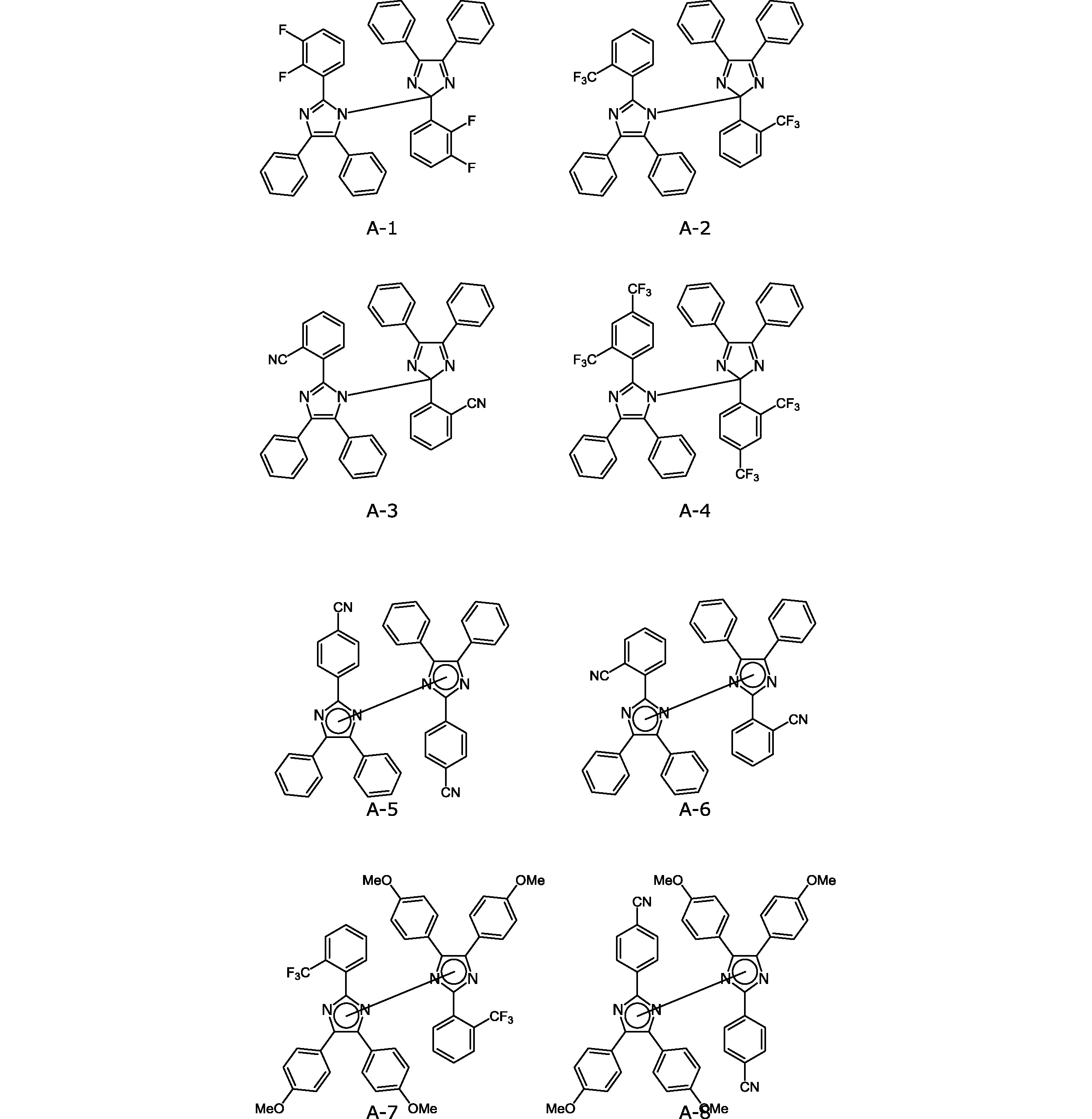
電子求引性置換基を持つヘキサアリールビスイミダゾール化合物A-1~A-4は、公知の方法(特開昭62-149668)、化合物A-5~A-8は、公知の方法(Bull. Chem. Soc. Japan, (1960), 33, 566)を参考に合成した。化合物A-5~A-8は、それぞれ、結合位置が異なる異性体の混合物を表す。
(ヘキサアリールビスイミダゾールの合成)
電子求引性置換基を持つヘキサアリールビスイミダゾール化合物A-1~A-4は、公知の方法(特開昭62-149668)、化合物A-5~A-8は、公知の方法(Bull. Chem. Soc. Japan, (1960), 33, 566)を参考に合成した。化合物A-5~A-8は、それぞれ、結合位置が異なる異性体の混合物を表す。
(比較ヘキサアリールビスイミダゾールの合成)
化合物B-4以外、化合物B-1~B-5は、公知の方法(特開昭62-149668)を参考に合成した。化合物B-4は、東京化成工業製のものを使用した。
化合物B-4以外、化合物B-1~B-5は、公知の方法(特開昭62-149668)を参考に合成した。化合物B-4は、東京化成工業製のものを使用した。
(ヘキサアリールビスイミダゾール溶液の調製)
化合物A-1(2.5mg)をアセトニトリル(14mL)に加え、超音波洗浄器を使用して完溶させ、溶液A-1を調製した(濃度:2.7×10⁻⁷M)。溶液A-1における化合物A-1を、A-2~A-8、B-1~B-5に、それぞれ等モル変更した以外は溶液A-1と同様にして、溶液A-2~A-8、B-1~B-5を調製した。
化合物A-1(2.5mg)をアセトニトリル(14mL)に加え、超音波洗浄器を使用して完溶させ、溶液A-1を調製した(濃度:2.7×10⁻⁷M)。溶液A-1における化合物A-1を、A-2~A-8、B-1~B-5に、それぞれ等モル変更した以外は溶液A-1と同様にして、溶液A-2~A-8、B-1~B-5を調製した。
(ラジカル寿命測定)
UV-Vis用石英セルに、先ほど調製した溶液A-1を入れ、紫外線照射装置を用いて2分間露光し、これをUV-Vis測定装置(日立製作所製)を用いて、室温中(25℃)放置時間に対する吸光度(光照射により可視領域に出現するラジカル由来のピークトップ)の減衰を測定した。この測定により求めた半減期(吸光度が半分になる時間)を表1に示す。
UV-Vis用石英セルに、先ほど調製した溶液A-1を入れ、紫外線照射装置を用いて2分間露光し、これをUV-Vis測定装置(日立製作所製)を用いて、室温中(25℃)放置時間に対する吸光度(光照射により可視領域に出現するラジカル由来のピークトップ)の減衰を測定した。この測定により求めた半減期(吸光度が半分になる時間)を表1に示す。
溶液A-2~A-8、B-1~B-5についても、溶液A-1と同様の測定を行った。この測定により求めた半減期を表1に示す。
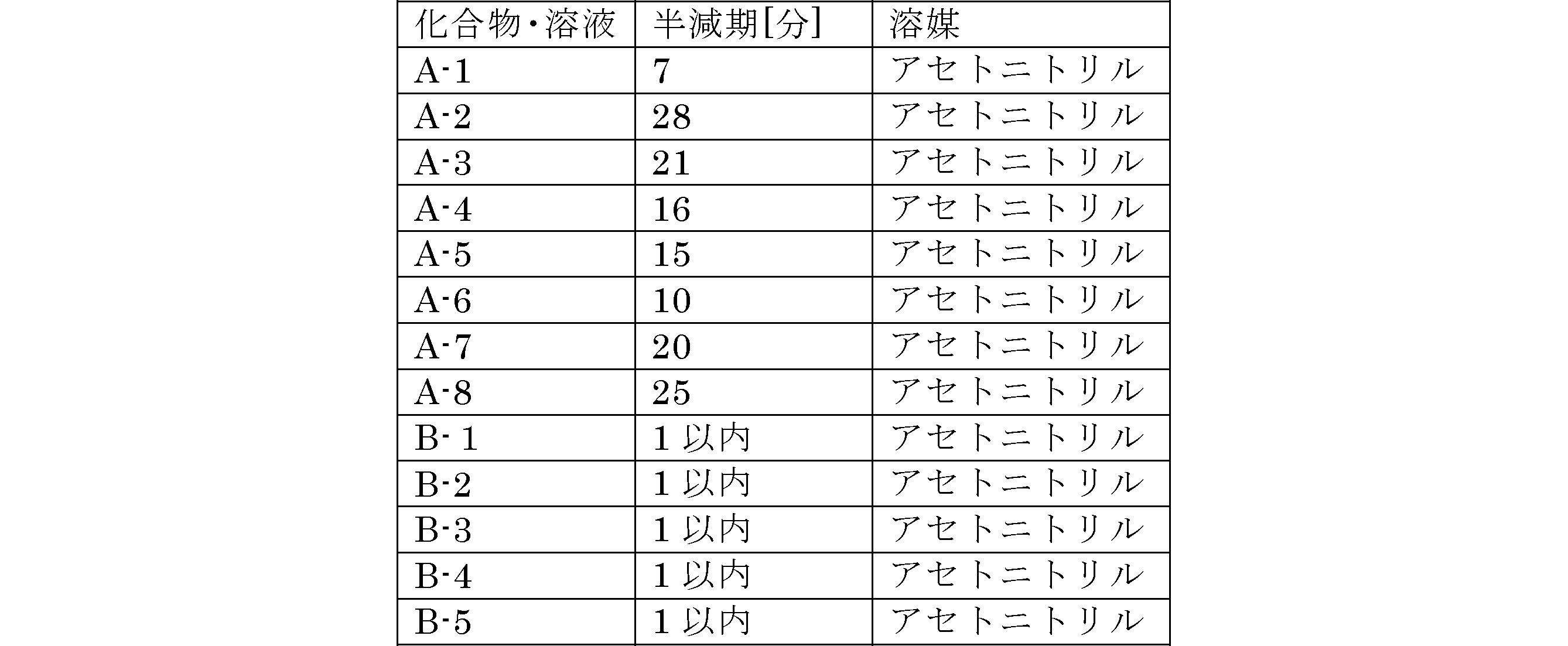
表1の結果から電子求引性置換基を持つヘキサアリールビスイミダゾールを含む溶液A-1~A-8は、溶液B-1~B-8に比べて、ラジカル状態が大幅に長寿命化していることが分かる。
<実験2>
(ヘキサアリールビスイミダゾール溶液の調製)
化合物A-1(50mg)を塩化メチレン(1.5mL)に加え、溶液a-1を調製した。溶液a-1における化合物A-1を、A-2~A-8に、それぞれ変更した以外は溶液a-1と同様にして、溶液a-2~a-8を調製した。
(ヘキサアリールビスイミダゾール溶液の調製)
化合物A-1(50mg)を塩化メチレン(1.5mL)に加え、溶液a-1を調製した。溶液a-1における化合物A-1を、A-2~A-8に、それぞれ変更した以外は溶液a-1と同様にして、溶液a-2~a-8を調製した。
(揮発性有機物検知体の作製)
ろ紙(Advantec社製、No.1 185mm)を、鋏を用いて4cm×2cmの大きさに切り、これを先ほど調製した溶液a-1に浸し、その後、取り出し、室温で乾燥させ、実施例1のサンプル(揮発性有機物検知体)を作製した。実施例1のサンプルにおける化合物A-1を、A-2~A-8に、それぞれ変更した以外は実施例1と同様にして、実施例2~8のサンプルを作製した。
ろ紙(Advantec社製、No.1 185mm)を、鋏を用いて4cm×2cmの大きさに切り、これを先ほど調製した溶液a-1に浸し、その後、取り出し、室温で乾燥させ、実施例1のサンプル(揮発性有機物検知体)を作製した。実施例1のサンプルにおける化合物A-1を、A-2~A-8に、それぞれ変更した以外は実施例1と同様にして、実施例2~8のサンプルを作製した。
(露光)
作製した実施例1のサンプルをUVランプ(UVGL-25 Compact UV Lamp、フナコシ社製)を用いて、1分間露光し、着色サンプルを得た。実施例1のサンプルと同様にして、実施例2~8の着色サンプルを得た。
作製した実施例1のサンプルをUVランプ(UVGL-25 Compact UV Lamp、フナコシ社製)を用いて、1分間露光し、着色サンプルを得た。実施例1のサンプルと同様にして、実施例2~8の着色サンプルを得た。
(有機蒸気暴露)
体積280mLのガラス容器に酢酸エチル50μLを、マイクロピペットを用いて滴下し、ガラス容器の蓋をした状態で、酢酸エチルが完全に気化するまで放置した。その後、実施例1のサンプルをガラス容器の中に入れ、蓋をした状態で5分間静置した。実施例2~8のサンプルについても同様に蒸気暴露試験を行った。結果を表2に示す。
体積280mLのガラス容器に酢酸エチル50μLを、マイクロピペットを用いて滴下し、ガラス容器の蓋をした状態で、酢酸エチルが完全に気化するまで放置した。その後、実施例1のサンプルをガラス容器の中に入れ、蓋をした状態で5分間静置した。実施例2~8のサンプルについても同様に蒸気暴露試験を行った。結果を表2に示す。
(消色判定)
着色サンプルが有機蒸気暴露試験後に消色した場合は○、色変化が起こらなかった場合は×とする。
着色サンプルが有機蒸気暴露試験後に消色した場合は○、色変化が起こらなかった場合は×とする。
(比較サンプル)
化合物A-7を含む溶液a-7を、支持体として、ろ紙を用いず、スライドガラス(MATSUNAMI社製S1214)を用いて、溶液をドロップキャストして膜を作製した以外は同様にして、比較例1のサンプルを作製し、同様の暴露試験を行った。結果を表2に示す。
化合物A-7を含む溶液a-7を、支持体として、ろ紙を用いず、スライドガラス(MATSUNAMI社製S1214)を用いて、溶液をドロップキャストして膜を作製した以外は同様にして、比較例1のサンプルを作製し、同様の暴露試験を行った。結果を表2に示す。
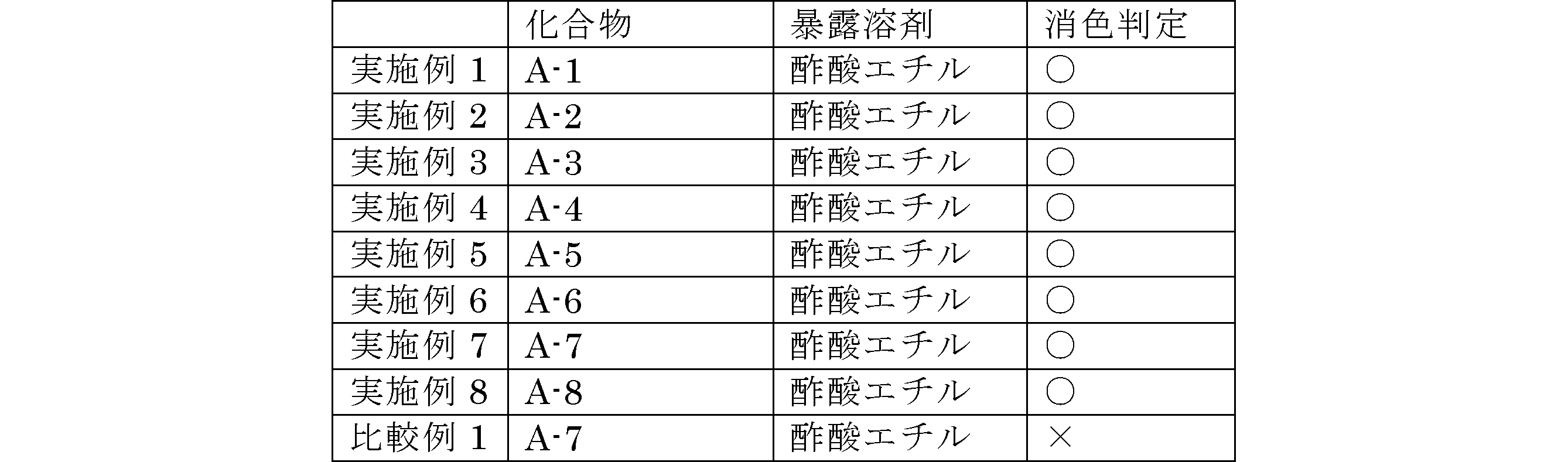
表2から、実施例1~8のサンプルが、酢酸エチルを検出できていることがわかる。
<実験3>
実施例2,7,8のサンプルに対して、有機蒸気暴露試験の溶剤を酢酸エチルから、n-ヘキサン、メタノール、アセトン、メチルエチルケトン、アセトニトリル、テトラヒドロフラン、トルエン、アンモニア、ホルムアルデヒドに変更して、消色判定を行った結果を表3に示す。
実施例2,7,8のサンプルに対して、有機蒸気暴露試験の溶剤を酢酸エチルから、n-ヘキサン、メタノール、アセトン、メチルエチルケトン、アセトニトリル、テトラヒドロフラン、トルエン、アンモニア、ホルムアルデヒドに変更して、消色判定を行った結果を表3に示す。
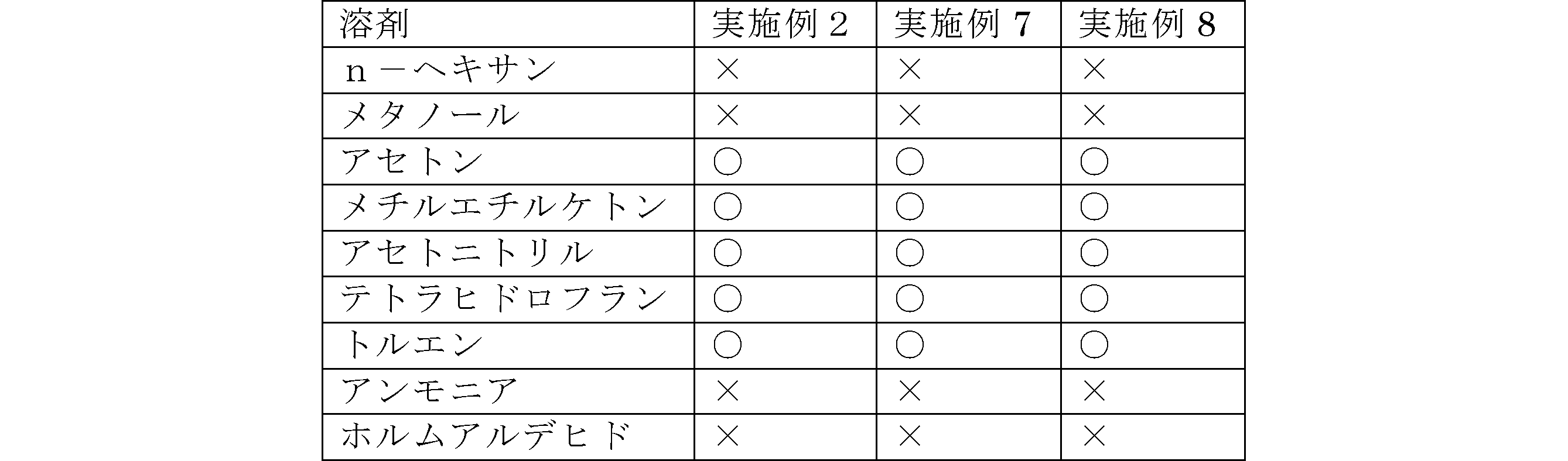
表3から、検出可能溶剤と検出不可能溶剤がはっきり区別できていることが分かる。
<実験4>
(繰り返し耐久性評価)
実験2と同様にUVランプを用いて露光、酢酸エチル蒸気の暴露試験を行い消色させた後、サンプルを、ホットプレート上で120℃に加熱し、消色させた。この一連の操作を20回繰り返した後、色が、初期状態と比較して変化するか検討した。サンプルとして実施例2,7,8のサンプルを用いた。色が大きく変化している場合は×、僅かに変化している場合は△、全く変化していない場合は○とする。その結果を表4に示す。
(繰り返し耐久性評価)
実験2と同様にUVランプを用いて露光、酢酸エチル蒸気の暴露試験を行い消色させた後、サンプルを、ホットプレート上で120℃に加熱し、消色させた。この一連の操作を20回繰り返した後、色が、初期状態と比較して変化するか検討した。サンプルとして実施例2,7,8のサンプルを用いた。色が大きく変化している場合は×、僅かに変化している場合は△、全く変化していない場合は○とする。その結果を表4に示す。

(揮発性有機物検知装置の実施例)
図2に示した揮発性有機物検知装置のモデル装置を作製した。検出用光源3としては、緑色LED(発光波長505~555nm)、活性化光源2としては、紫外線蛍光管(中心発光波長254nm)を使用した。紫外線蛍光管で1分間照射した後、緑色LEDを発光させ、フォトダイオード(受光部4)で反射光における吸収強度を計測し、それを1とした。流量制御部7から、2%のアセトン蒸気を300mL導入したところで、再度緑色LEDを発光させ、フォトダイオードで反射光における吸収強度を計測したところ、0.2であった。ヒーターで100℃に加熱し、再度紫外線蛍光管を照射することで、吸収強度が1付近まで回復することを確認した。
図2に示した揮発性有機物検知装置のモデル装置を作製した。検出用光源3としては、緑色LED(発光波長505~555nm)、活性化光源2としては、紫外線蛍光管(中心発光波長254nm)を使用した。紫外線蛍光管で1分間照射した後、緑色LEDを発光させ、フォトダイオード(受光部4)で反射光における吸収強度を計測し、それを1とした。流量制御部7から、2%のアセトン蒸気を300mL導入したところで、再度緑色LEDを発光させ、フォトダイオードで反射光における吸収強度を計測したところ、0.2であった。ヒーターで100℃に加熱し、再度紫外線蛍光管を照射することで、吸収強度が1付近まで回復することを確認した。
以上、本発明の例示的な実施形態および実施例について説明した。
本実施形態に係る揮発性有機物検知体は、基体と、基体に含まれる、上記一般式(1)で表されるヘキサアリールビスイミダゾールと、を備える。これにより、検知対象となる揮発性有機物の選択性が高く、動作温度が低く、安定化するまでの時間が短い、揮発性有機物検知体を提供できる。
好ましくは、基体は、セルロースを含有する。これにより、消色効果を促進することができる。
好ましくは、一般式(1)中、R1~R30のいずれか少なくとも一つが、フッ素原子、フッ素化アルキル基又はシアノ基から選択される置換基である。これによりTPIRの安定性を向上でき、繰り返し耐久性を向上できる。
好ましくは、一般式(1)中、R1~R5、R16~R20のいずれか少なくとも一つが、フッ素原子、フッ素化アルキル基又はシアノ基から選択される置換基である。これによりTPIRの安定性を向上でき、繰り返し耐久性を向上できる。
本実施形態に係る揮発性有機物検知体の製造方法は、基体に上記一般式(1)で表されるヘキサアリールビスイミダゾールを含浸させる工程と、基体を乾燥させる工程と、を含む。本実施形態によれば、上述した性能をもつ揮発性有機物検知体を安価に製造できる。
本実施形態に係る揮発性有機物の検知方法は、上述した揮発性有機物検知体に電磁波を照射して着色させる工程と、揮発性有機物の存在に基づく揮発性有機物検知体の消色を検知する工程と、を含む。これにより、検知対象となる揮発性有機物の選択性が高く、動作温度が低く、安定化するまでの時間が短い、揮発性有機物の検知方法を提供できる。
本実施形態に係る揮発性有機物検知装置は、上述した揮発性有機物検知体と、揮発性有機物検知体に電磁波を照射して着色させる着色手段と、揮発性有機物の存在に基づく揮発性有機物検知体の消色を検知する消色検知手段と、を備える。これにより、検知対象となる揮発性有機物の選択性が高く、高温動作部が不要で、安定化するまでの時間が短い、揮発性有機物検知装置を提供できる。
消色検知手段は、揮発性有機物検知体に500~600nmの波長の検出光を照射する検出用光源と、揮発性有機物検知体を通過又は反射した検出光の強度を検出する検出用受光部と、を備える。これにより、揮発性有機物の存在に基づく揮発性有機物検知体の消色を数値化でき、精度よく検知できる。
揮発性有機物検知体を加熱する加熱部をさらに備える。これにより、測定終了後、加熱部により揮発性有機物検知体を加熱することで消色でき、揮発性有機物検知体を着色前の初期状態に戻すことができる。よって、揮発性有機物検知体の再利用が可能になる。
以上説明した実施形態は、本発明の理解を容易にするためのものであり、本発明を限定して解釈するためのものではない。実施形態が備える各要素並びにその配置、材料、条件、形状及びサイズ等は、例示したものに限定されるわけではなく適宜変更することができる。また、異なる実施形態で示した構成同士を部分的に置換し又は組み合わせることが可能である。
1…揮発性有機物検知体、2…活性化光源(着色手段)、3…検出用光源、4…受光部、5…加熱部、6…筐体、6a,6b…孔部、7…流量制御部、8…演算部、9…記憶部、10…揮発性有機物検知装置、11…対象気体
Claims (9)
- 基体と、
前記基体に含まれる、下記一般式(1)で表されるヘキサアリールビスイミダゾールと、
を備える、揮発性有機物検知体。

- 前記基体は、セルロースを含有する、
請求項1に記載の揮発性有機物検知体。 - 前記一般式(1)中、R1~R30のいずれか少なくとも一つが、フッ素原子、フッ素化アルキル基又はシアノ基から選択される置換基である、
請求項1又は2に記載の揮発性有機物検知体。 - 前記一般式(1)中、R1~R5、R16~R20のいずれか少なくとも一つが、フッ素原子、フッ素化アルキル基又はシアノ基から選択される置換基である、
請求項1から3のいずれか一項に記載の揮発性有機物検知体。 - 基体に下記一般式(1)で表されるヘキサアリールビスイミダゾールを含浸させる工程と、
前記基体を乾燥させる工程と、
を含む、揮発性有機物検知体の製造方法。

- 請求項1から4のいずれか一項に記載の揮発性有機物検知体に電磁波を照射して着色させる工程と、
揮発性有機物の存在に基づく前記揮発性有機物検知体の消色を検知する工程と、
を含む、揮発性有機物の検知方法。 - 請求項1から4のいずれか一項に記載の揮発性有機物検知体と、
前記揮発性有機物検知体に電磁波を照射して着色させる着色手段と、
揮発性有機物の存在に基づく前記揮発性有機物検知体の消色を検知する消色検知手段と、
を備える、揮発性有機物検知装置。 - 前記消色検知手段は、
前記揮発性有機物検知体に500~600nmの波長の検出光を照射する検出用光源と、
前記揮発性有機物検知体を通過又は反射した前記検出光の強度を検出する検出用受光部と、
を備える、請求項7記載の揮発性有機物検知装置。 - 前記揮発性有機物検知体を加熱する加熱部をさらに備える、
請求項7又は8に記載の揮発性有機物検知装置。
Applications Claiming Priority (2)
| Application Number | Priority Date | Filing Date | Title |
|---|---|---|---|
| JP2016-200386 | 2016-10-11 | ||
| JP2016200386 | 2016-10-11 |
Publications (1)
| Publication Number | Publication Date |
|---|---|
| WO2018070360A1 true WO2018070360A1 (ja) | 2018-04-19 |
Family
ID=61905501
Family Applications (1)
| Application Number | Title | Priority Date | Filing Date |
|---|---|---|---|
| PCT/JP2017/036572 Ceased WO2018070360A1 (ja) | 2016-10-11 | 2017-10-10 | 揮発性有機物検知体及びその製造方法、揮発性有機物の検知方法並びに揮発性有機物検知装置 |
Country Status (1)
| Country | Link |
|---|---|
| WO (1) | WO2018070360A1 (ja) |
Cited By (1)
| Publication number | Priority date | Publication date | Assignee | Title |
|---|---|---|---|---|
| CN113466221A (zh) * | 2021-06-23 | 2021-10-01 | 重庆大学 | 一种高分子材料热真空稳定性测试装置及测试方法 |
Citations (5)
| Publication number | Priority date | Publication date | Assignee | Title |
|---|---|---|---|---|
| US5501945A (en) * | 1994-08-30 | 1996-03-26 | The University Of Akron | Method of using multichromic polymers in packaging |
| JPH11125901A (ja) * | 1997-08-19 | 1999-05-11 | Dainippon Printing Co Ltd | 感光性樹脂フイルム、該フイルムを用いる蛍光体パターンの形成方法、該フイルムを用いるプラズマディスプレイパネル用背面板の製造方法、該製造方法により得られたプラズマディスプレイパネル用背面板及びプラズマディスプレイパネル |
| JP2010501655A (ja) * | 2006-08-24 | 2010-01-21 | チバ ホールディング インコーポレーテッド | Uv線量インジケータ |
| CN101709998A (zh) * | 2009-10-13 | 2010-05-19 | 刘灿 | 节能、便携式紫外指数测量仪 |
| JP2010209047A (ja) * | 2009-03-12 | 2010-09-24 | Tokyo Institute Of Technology | フェニルテルピリジン化合物、錯化合物または複合体及びそれらの製造方法並びにそれらを含む発光体及び有機化合物の検出材 |
-
2017
- 2017-10-10 WO PCT/JP2017/036572 patent/WO2018070360A1/ja not_active Ceased
Patent Citations (5)
| Publication number | Priority date | Publication date | Assignee | Title |
|---|---|---|---|---|
| US5501945A (en) * | 1994-08-30 | 1996-03-26 | The University Of Akron | Method of using multichromic polymers in packaging |
| JPH11125901A (ja) * | 1997-08-19 | 1999-05-11 | Dainippon Printing Co Ltd | 感光性樹脂フイルム、該フイルムを用いる蛍光体パターンの形成方法、該フイルムを用いるプラズマディスプレイパネル用背面板の製造方法、該製造方法により得られたプラズマディスプレイパネル用背面板及びプラズマディスプレイパネル |
| JP2010501655A (ja) * | 2006-08-24 | 2010-01-21 | チバ ホールディング インコーポレーテッド | Uv線量インジケータ |
| JP2010209047A (ja) * | 2009-03-12 | 2010-09-24 | Tokyo Institute Of Technology | フェニルテルピリジン化合物、錯化合物または複合体及びそれらの製造方法並びにそれらを含む発光体及び有機化合物の検出材 |
| CN101709998A (zh) * | 2009-10-13 | 2010-05-19 | 刘灿 | 节能、便携式紫外指数测量仪 |
Non-Patent Citations (4)
| Title |
|---|
| ABE JIRO: "Novel fast photochromic molecules based on hexaarylbisimidazoles", THE CHEMICAL TIMES, no. 2, 2009, pages 8 - 12 * |
| SCHROEDNER M: "Oscillations of the lophyl radical concentration during the photo-decomposition of o-Cl-hexaarylimidazole", J PHOTOCHEM PHOTOBIOL A CHEM, vol. 233, 1 April 2012 (2012-04-01), pages 60 - 64, XP028478456, DOI: doi:10.1016/j.jphotochem.2012.02.013 * |
| SMETS G ET AL.: "Dissociation and recombination reaction in solid polymers", JOURNAL OF POLYMER SCIENCE: POLYMER SYMPOSIA, vol. 67, 1980, pages 83 - 98, XP055604324, ISSN: 0360-8905, DOI: 10.1002/polc.5070670107 * |
| WANG BAO-HU ET AL.: "High Efficient Photoinitiator of Hexaphenylbisimidazole Derivatives with Substituents in the 2-Phenyl Ring", JOURNAL OF PHOTOPOLYMER SCIENCE AND TECHNOLOGY, vol. 24, no. 6, 2011, pages 611 - 615, XP055604330, DOI: 10.2494/photopolymer.24.611 * |
Cited By (1)
| Publication number | Priority date | Publication date | Assignee | Title |
|---|---|---|---|---|
| CN113466221A (zh) * | 2021-06-23 | 2021-10-01 | 重庆大学 | 一种高分子材料热真空稳定性测试装置及测试方法 |
Similar Documents
| Publication | Publication Date | Title |
|---|---|---|
| JP6652248B2 (ja) | 空気中、溶液中および拭き取り試料からのNOxベースの爆発物を検出するための蛍光染料フィルム、検出試薬、方法、分析物感知層の生成方法、分析物感知層、及び、使用 | |
| CN109073561B (zh) | 有机化学物的检测 | |
| KR19980018630A (ko) | 가스 반응성 안료를 사용하는 가스 검출 방법 및 가스 반응 장치 | |
| WO2003091724A1 (en) | Method of measuring formaldehyde concentration of gas and measuring instrument | |
| JPH11108833A (ja) | 物質の分光分析法 | |
| WO2018070360A1 (ja) | 揮発性有機物検知体及びその製造方法、揮発性有機物の検知方法並びに揮発性有機物検知装置 | |
| Marco et al. | Spiropyran-based chromic hydrogels for CO2 absorption and detection | |
| KR20150120249A (ko) | 가스 중의 포름알데히드 농도의 측정방법 및 측정장치 | |
| JP3889989B2 (ja) | ガス中のホルムアルデヒド濃度の測定方法および測定装置 | |
| JP6787555B2 (ja) | 爆発物の検出のための蛍光シラン層 | |
| Tao et al. | A novel cataluminescence gas sensor based on MgO thin film | |
| Kaur et al. | A dual-mode visual detector for toxic hydrazine | |
| Hauser et al. | Atomic absorption determination of cadmium and lead in whole blood by a reagent-free method | |
| Hallett‐Tapley et al. | Absolute reactivity of arylallyl carbocations | |
| JP3835600B2 (ja) | 酸素濃度計測素子とその製造方法 | |
| JP5665001B2 (ja) | 検出方法及び検出センサー | |
| Ramotowski | Vapor/fuming methods | |
| JP3173694B2 (ja) | 塩基性ガス検知テープ | |
| Leaver | Sensitized Photooxidation of Wool by Fluorescent Whitening Agents. A Direct Spectral Study | |
| JP3828427B2 (ja) | ホルムアルデヒド測定用試薬及びそれを用いたホルムアルデヒドの測定方法 | |
| JP5481689B2 (ja) | イオン測定用オプトード及びそれを用いたイオン濃度の測定方法 | |
| ES3015115T3 (en) | Method and sensor for detection of triacetone triperoxide (tatp), diacetone diperoxide (dadp), hexamethylene triperoxide diamine (hmtd) and hydrogen peroxide | |
| JP2010175268A (ja) | ガス測定装置および方法 | |
| Sharma et al. | Galvinol as ratiometric naked-eye colorimetric moisture sensor: Synthesis process development, applications and mechanistic studies | |
| CN101566596B (zh) | 空气中氨浓度检测用的氨敏材料的制备方法 |
Legal Events
| Date | Code | Title | Description |
|---|---|---|---|
| 121 | Ep: the epo has been informed by wipo that ep was designated in this application |
Ref document number: 17861166 Country of ref document: EP Kind code of ref document: A1 |
|
| NENP | Non-entry into the national phase |
Ref country code: DE |
|
| 122 | Ep: pct application non-entry in european phase |
Ref document number: 17861166 Country of ref document: EP Kind code of ref document: A1 |
|
| NENP | Non-entry into the national phase |
Ref country code: JP |