WO2018070186A1 - 電子制御装置及びエバポリーク診断装置 - Google Patents
電子制御装置及びエバポリーク診断装置 Download PDFInfo
- Publication number
- WO2018070186A1 WO2018070186A1 PCT/JP2017/033403 JP2017033403W WO2018070186A1 WO 2018070186 A1 WO2018070186 A1 WO 2018070186A1 JP 2017033403 W JP2017033403 W JP 2017033403W WO 2018070186 A1 WO2018070186 A1 WO 2018070186A1
- Authority
- WO
- WIPO (PCT)
- Prior art keywords
- protection circuit
- reverse connection
- operation mode
- connection protection
- power supply
- Prior art date
- Legal status (The legal status is an assumption and is not a legal conclusion. Google has not performed a legal analysis and makes no representation as to the accuracy of the status listed.)
- Ceased
Links
Images

Classifications
-
- B—PERFORMING OPERATIONS; TRANSPORTING
- B60—VEHICLES IN GENERAL
- B60R—VEHICLES, VEHICLE FITTINGS, OR VEHICLE PARTS, NOT OTHERWISE PROVIDED FOR
- B60R16/00—Electric or fluid circuits specially adapted for vehicles and not otherwise provided for; Arrangement of elements of electric or fluid circuits specially adapted for vehicles and not otherwise provided for
- B60R16/02—Electric or fluid circuits specially adapted for vehicles and not otherwise provided for; Arrangement of elements of electric or fluid circuits specially adapted for vehicles and not otherwise provided for electric constitutive elements
-
- H—ELECTRICITY
- H02—GENERATION; CONVERSION OR DISTRIBUTION OF ELECTRIC POWER
- H02H—EMERGENCY PROTECTIVE CIRCUIT ARRANGEMENTS
- H02H11/00—Emergency protective circuit arrangements for preventing the switching-on in case an undesired electric working condition might result
-
- H—ELECTRICITY
- H02—GENERATION; CONVERSION OR DISTRIBUTION OF ELECTRIC POWER
- H02J—ELECTRIC POWER NETWORKS; CIRCUIT ARRANGEMENTS OR SYSTEMS FOR SUPPLYING OR DISTRIBUTING ELECTRIC POWER; SYSTEMS FOR STORING ELECTRIC ENERGY
- H02J7/00—Circuit arrangements for charging or discharging batteries or for supplying loads from batteries
Definitions
- the present invention relates to an electronic control device provided with a protection circuit for protecting when an external power supply is not normal, and an evaporation diagnosis device using this electronic control device.
- an electronic control device mounted on an automobile operates with an in-vehicle battery as a power source, a power terminal connected to the plus terminal of the in-vehicle battery, and a ground terminal connected to the minus terminal of the battery It has.
- power from the in-vehicle battery is supplied to a power supply target such as an internal control circuit or an external electric load via a power supply terminal and a ground terminal.
- the in-vehicle battery is connected in reverse (that is, the negative terminal of the in-vehicle battery is connected to the power terminal, and the positive terminal of the in-vehicle battery is connected to the ground terminal. If no measures are taken against such reverse connection of the in-vehicle battery, a current in the reverse direction flows to the power supply target such as the control circuit, and the power supply There is a risk of adversely affecting the supply.
- a reverse connection protection circuit is connected to the positive terminal of the in-vehicle battery so as to avoid adverse effects during reverse connection.
- a reverse connection protection circuit is already used in products and is well known.
- the reverse connection protection circuit is connected to the ground through a predetermined resistor, and therefore, a current (darkness) of several milliamperes is always generated from the reverse connection circuit. Current) flows toward the ground, and there is a problem in that the power of the in-vehicle battery is wasted.
- Patent Document 1 in an in-vehicle electronic control device, an arithmetic device is supplied by supplying power to an arithmetic device from a power circuit connected to the in-vehicle battery using an external power switch signal as a trigger.
- the reverse connection protection circuit is opened by outputting an open instruction signal for the reverse connection protection circuit from the activated arithmetic device.
- Patent Document 2 Japanese Patent Laid-Open No. 2007-082374
- the charge pump When the charge pump is activated, the reverse connection protection circuit is closed and power is supplied from the in-vehicle battery to the control circuit.
- the electronic control unit Conversely, when the electronic control unit is on standby, the charge pump does not operate when the external switch is turned off.
- the reverse connection protection circuit is in an open circuit state to stop power supply from the in-vehicle battery to the control circuit.
- Patent Document 1 since it is necessary to supply power from the power supply circuit to the arithmetic unit using an external power switch signal as a trigger, the power circuit constantly monitors the input of the external power switch signal. It has become. Therefore, it is necessary for current to flow through the power supply circuit even when the automobile is stopped, and there is a problem that power consumption occurs constantly in the power supply circuit.
- Patent Document 2 power is supplied to the electronic control circuit by closing the reverse connection protection circuit using an external switch.
- the charge for operating the reverse connection protection circuit that is directly connected to the vehicle battery is used. Since the pump is grounded with the ground, even if the reverse connection protection circuit is off, a path for current to flow constantly from the charge pump to the ground is created, so that the reverse connection protection circuit can prevent power consumption even when the vehicle is stopped. There is a problem that consumption occurs constantly.
- An object of the present invention is to provide a protection circuit for coping with at least a case where the power supply is not normal while the electronic control unit is on standby, an arithmetic device for controlling the protection circuit, and supplying power to the arithmetic device. It is an object of the present invention to provide an electronic control device that minimizes the power consumed by the power supply circuit, and an evaporation diagnostic device that uses this electronic control device.
- a feature of the present invention is that the input side is connected to a power supply, and the output side is connected to a power supply circuit that supplies power to the arithmetic unit, and power is supplied to the power supply circuit in the operation mode, and power is supplied to the power supply circuit in the non-operation mode.
- a standby mode in which a protection circuit having a function of not supplying and a protection circuit operation switching means for controlling the operation of this protection circuit is provided and the electronic control device is on standby.
- a start signal different from that by the arithmetic unit has arrived
- the protection circuit operation switching means is operated based on the start signal to switch the protection circuit to the operation mode.
- the protection circuit operation switching means is based on the non-operation instruction signal. Is operated to switch the protection circuit to the non-operation mode.
- the arithmetic circuit that controls the protection circuit by setting the protection circuit to the non-operation mode by the protection circuit operation switching means that operates based on the non-operation instruction signal from the arithmetic device and setting the protection circuit to the non-operation mode. Since no power is supplied to the power supply circuit that supplies power to the arithmetic device, the power consumed by the protection circuit, the arithmetic device, and the power supply circuit is reduced as much as possible while the electronic control device is on standby. Can do.
- FIG. 1 shows a circuit configuration of an electronic control device according to a typical embodiment of the present invention
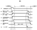
- FIG. 2 shows a timing chart for explaining the operation of the electronic control device during transition between a standby state and an operation state.
- An electronic control device according to the present embodiment described below has a function of executing an evacueque diagnosis.
- the present invention can be applied to an electronic control device other than the evaporative diagnosis device.
- Evaporated fuel that leaks into the atmosphere from a fuel supply system such as a fuel tank of an automobile contains a large amount of hydrocarbons (HC) and is one of the causes of air pollution.
- a fuel supply system such as a fuel tank of an automobile contains a large amount of hydrocarbons (HC) and is one of the causes of air pollution.
- HC hydrocarbons
- Various techniques are known for preventing the release of the evaporated fuel, and a representative example thereof includes a canister that temporarily stores evaporated fuel generated in a fuel supply system of an internal combustion engine such as a fuel tank, There is an evaporation purge device that releases evaporated fuel adsorbed on a canister during operation of an internal combustion engine and discharges it to an intake passage.
- the fresh air passage of the canister communicates with the air passage between the air flow meter and the throttle valve via the control valve and the atmosphere.
- the fresh air passage of the canister Some control valves are connected to an intake passage between a meter and a throttle valve and control a control valve to connect a fresh air passage to the atmosphere when the internal combustion engine is driven.
- the electronic control unit (C / U) 10 has at least a function of executing the evaporative diagnosis.
- the main components of the electronic control device 10 related to the present embodiment are a reverse connection protection circuit 11, a power supply circuit 12, and an arithmetic device 13 as protection circuits when the power supply is not normal.
- the reverse connection protection circuit 11 has a function for protecting the electronic control device when the in-vehicle battery is reversely connected.
- the power supply circuit 12 is a power supply for the subsequent arithmetic device 13 and generates a voltage (about 5 V) at which the microcomputer constituting the arithmetic device 13 can operate.
- the arithmetic unit 13 executes various control functions, such as fuel control, ignition control, EGR control, diagnostic control, etc., and the diagnostic control has at least an evaporation diagnostic function.
- the electronic control device 10 may be provided with only an evaporative diagnosis function.
- the input side terminal 11in of the reverse connection protection circuit 11 is connected to the in-vehicle battery 14, and the output side terminal 11out is connected to the input side terminal 12in of the power supply circuit 12.
- the output side terminal 12out of the power supply circuit 12 is connected to the input side terminal 13in of the arithmetic device 13. Therefore, when the electronic control device 10 is operating normally, power is supplied from the in-vehicle battery 14 to the reverse connection protection circuit 11, the power supply circuit 12, and the arithmetic device 13.
- the reverse connection protection circuit 11 includes a charge pump 11p, an internal switch element (FET) 11s, a Zener diode 11zd that connects the source S and drain D of the internal switch element 11s, and a diode 11d that allows current to flow from the source S to the charge pump 11p.
- the zener diode 11zd prevents the current from flowing from the drain D to the ground Grd.
- the voltage Vin is applied from the in-vehicle battery 14 and is supplied to the charge pump 11p, so that the gate G of the internal switch element 11s is turned on and the voltage Vout is output, and the power supply circuit 12 and other controls are performed. Can power the system.
- the gate G of the internal switch element 11s is turned off, and the control system is protected from reverse connection.
- This reverse connection protection circuit 11 has a well-known configuration.
- a “switching control unit” that constitutes a “protection circuit operation switching unit” that switches the operating state (operation mode / non-operation mode) of the resistor 15 and the reverse connection protection circuit 11 is provided.
- the switching control switch element 16 When the switching control switch element 16 is turned on, when the switching control switch element 16 is turned on, the charge pump 11p is connected to the ground via the resistor 15 and the collector C and emitter E of the switching control switch element 16. A current flows toward Grd, the reverse connection protection circuit 11 enters an operation mode, and the voltage Vout from the in-vehicle battery 14 is output to the output terminal 11out.
- the output side terminal 11out of the reverse connection protection circuit 11 is connected to the start signal input terminal 17, and a trigger signal of a momentary switch such as the fuel supply switch 18 and a diagnosis start signal are input to the start signal input terminal 17.
- a momentary switch signal is a pulse-shaped signal having a rising edge and a falling edge, and is a switch signal that rises by a push-down operation and falls by a push-up action like the oil supply switch 18.
- the diagnosis start signal is a pulse-shaped signal having a rising edge and a falling edge that arrives every predetermined time (for example, every 3 hours), and when this signal arrives, the arithmetic unit 13 performs an evaporative diagnosis for a predetermined time. Is what you do.
- the diagnosis start signal is sent from the CAN bus line 19 and is a diagnosis instruction signal sent from another electronic control unit (arithmetic unit) (not shown). Therefore, when a diagnosis start signal for performing an evacueque diagnosis is received from another electronic control unit via the CAN bus line 19, the arithmetic unit 13 executes the epapolik diagnosis.
- a diagnosis start signal will be described as an example of a signal input to the activation signal input terminal 17.
- the base B of the switching control switch element 16 is connected at the connection point 20 between the start signal input terminal 17 and the output side terminal 11out of the reverse connection protection circuit 11.
- a first current direction limiting diode that allows current to flow from the output side terminal 11out of the reverse connection protection circuit 11 toward the connection point 20 between the connection point 20 and the output side terminal 11out of the reverse connection protection circuit 11 21d1 is provided.
- a second current direction limiting diode 21 d 2 is provided between the connection point 20 and the activation signal input terminal 17 to allow a current to flow from the activation signal input terminal 17 toward the connection point 20.
- the second current direction limiting diode 21d2 has a function of applying a diagnosis start signal to the base B of the switching control switch element 16 and starting the switching control switch element 16 in an ON state when a diagnosis start signal arrives at the start signal input terminal 17. It has.
- the first current direction limiting diode 21d1 applies the voltage Vout output to the output side terminal 11out of the reverse connection protection circuit 1 to the base B of the switching control switch element 16 to turn the switching control switch element 16 on. Has the function to maintain.
- a collector C of a reset switch element 22 made of a transistor, which is a “non-operation instruction means” for disabling the operation of the reverse connection protection circuit 11, is connected to the connection point 20, and the emitter E supplies a current to the ground. Connected to flow.
- the reset switch element 22 constitutes “protection circuit operation switching means” in cooperation with the switching control switch element 16.
- a reset signal that is a “non-operation instruction signal” from the arithmetic device 13 is input to the base B of the reset switch element 22.
- the reset switch element 22 functions to draw current from the connection point 20 and flow it to the ground Grd.
- the switching control switch element 16 is turned off and the reverse connection protection circuit 11 transits to the non-operation mode.
- the reverse connection protection circuit 11 has the input side terminal 11in connected to the in-vehicle battery 14 and the output side terminal 11out connected to the power supply circuit 12 that supplies power to the arithmetic device 13.
- a switching control switch element 16 for controlling the operation of the reverse connection protection circuit 11 is provided.
- the reverse connection protection circuit 11 is set to the operation mode by the switching control switch element 16 that operates based on the diagnosis start signal that arrives separately from the arithmetic device 13, and further, based on the reset signal from the arithmetic device 13.
- the reverse connection protection circuit 11 is set to the non-operation mode by the switching control switch element 16 that operates in this manner.
- the reverse connection protection circuit 11 having the configuration shown in FIG. 1 is used.
- this reverse connection protection circuit 11 is shown as an example, and other configurations are used.
- the reverse connection protection circuit 11 can also be used.
- the changeover control switch element 16 and the reset switch element 22 need to be switched between the operation mode and the non-operation mode.
- This timing chart is a timing chart at the time of performing an evaporative diagnosis, and once every predetermined time (about every 3 hours) in the standby mode in which the automobile is stopped and the electronic control unit 10 is on standby. Only when the diagnosis start signal arrives, the evaporative diagnosis is executed.
- this diagnosis start signal passes through the second current direction limiting diode 21d2 to the base B of the switching control switch element 16. Applied.
- the reverse connection protection circuit 11 and the ground Grd are brought into conduction. As a result, the reverse connection protection circuit 11 shifts to the operation mode.
- the voltage Vout of the output side terminal 11out of the reverse connection protection circuit 11 is applied to the power supply circuit 12, and as shown in (c), the switching control switch from the connection point 20 via the first current direction limiting diode 21d1. Applied to the base B of the element 16. Since the second current direction limiting diode 21d2 is provided, the current based on the voltage Vout does not flow to the start signal input terminal 17 side.
- the voltage Vout of the output side terminal 11out of the reverse connection protection circuit 11 is applied to the base B of the switching control switch element 16 as shown in (c). Since the voltage is applied, the switching control switch element 16 can be maintained in the ON state, and the reverse connection protection circuit 11 can be maintained in the operation mode.
- the computing measure 13 executes an evacueque diagnosis based on the diagnostic program.
- the diagnosis timer is activated to measure the time for executing the evaporative diagnosis.
- the diagnosis timer detects that a predetermined period (for example, 60 seconds) has elapsed
- the arithmetic unit 13 generates a reset signal at time t4 as shown in (g). Note that the reset signal may be generated by detecting not the elapsed time but the time point at which the evaporative diagnosis is completed.
- the current from the input side terminal 11in of the reverse connection protection circuit 11 to the charge pump 11p is cut off to turn off the internal switch element 11s, thereby the voltage of the output side terminal 11out of the reverse connection protection circuit 11 Vout also falls as shown in (d), and the non-operation mode is set. Since the voltage Vout at the output side terminal 11out of the reverse connection protection circuit 11 is substantially “0”, the supply of power to the power supply circuit 12 is stopped.
- the voltage Vout is not applied to the base B of the changeover control switch element 16, so that the changeover control switch element 16 maintains the off state and the reverse connection protection circuit 11 can be maintained in a non-operating mode.
- the operation of the reverse connection protection circuit 11 is stopped by the reset signal of the arithmetic device 13 to enter the non-operation mode, and the power supply is cut off by the reverse connection protection circuit 11 being in the non-operation mode,
- the arithmetic circuit is also brought into a non-operating state. Accordingly, at least the reverse connection protection circuit 11, the arithmetic device 13 that controls the reverse connection protection circuit 11, and the power supply circuit 12 that supplies power to the arithmetic device 13 in the standby mode in which the electronic control device is on standby. It is possible to reduce the power consumed by the power as much as possible.
- the electronic control device described above has been described by taking the evaporation diagnosis as an example.
- the present invention is not limited to this and can be applied to an electronic control device that is required to suppress current consumption during standby of the electronic control device.
- the present invention is not limited to this and can be applied to an electronic control device that is required to suppress current consumption during standby of the electronic control device.
- the input side is connected to the power supply, and the output side is connected to the power supply circuit that supplies power to the arithmetic device, and the power is supplied to the power supply circuit in the operation mode and in the non-operation mode.
- a protection circuit having a function of not supplying power to the power supply circuit and a protection circuit operation switching means for controlling the operation of the protection circuit are provided.
- the protection circuit operation switching means is operated based on this activation signal to switch the protection circuit to the operation mode.
- a non-operation instruction signal from the arithmetic unit arrives, The protection circuit operation switching means is operated to switch the protection circuit to the non-operation mode.
- the arithmetic device that controls the protection circuit by setting the protection circuit to the non-operation mode by the protection circuit operation switching means that operates based on the non-operation instruction signal from the arithmetic device and setting the protection circuit to the non-operation mode. Since no power is supplied to the power supply circuit that supplies power to the arithmetic device, the power consumed by the protection circuit, the arithmetic device, and the power supply circuit is reduced as much as possible while the electronic control device is on standby. be able to.
- this invention is not limited to above-described embodiment, Various modifications are included.
- the above-described embodiment has been described in detail for easy understanding of the present invention, and is not necessarily limited to one having all the configurations described.
- a part of the configuration of an embodiment can be replaced with the configuration of another embodiment, and the configuration of another embodiment can be added to the configuration of an embodiment.
Landscapes
- Engineering & Computer Science (AREA)
- Power Engineering (AREA)
- Mechanical Engineering (AREA)
- Supplying Secondary Fuel Or The Like To Fuel, Air Or Fuel-Air Mixtures (AREA)
- Charge And Discharge Circuits For Batteries Or The Like (AREA)
- Direct Current Feeding And Distribution (AREA)
- Continuous-Control Power Sources That Use Transistors (AREA)
Abstract
電子制御装置を待機させている状態で、逆接続保護回路、及びこの逆接続保護回路を制御する演算装置、及びこの演算装置に電力を供給する電源回路で消費される電力を極力少なくする電子制御装置を提供することにある。 入力側が車載バッテリと接続され、出力側が演算装置に電力を供給する電源回路12と接続された逆接続保護回路11の動作を制御する切換制御スイッチ素子16を設け、演算装置13とは別に到来する起動信号に基づいて動作する切換制御スイッチ素子16によって逆接続保護回路11を動作モードとし、演算装置13からのリセット信号に基づいて動作する切換制御スイッチ素子16によって逆接続保護回路11を非動作モードとする。逆接続保護回路を非動作モードとすることで、電源回路及び演算装置に電力を供給しなくなるので、逆接続保護回路、演算装置、及び電源回路で消費される電力を少なくすることができる。
Description
本発明は外部の電源が正常でない場合の保護を行う保護回路を備えた電子制御装置、及びこの電子制御装置を使用したエバポリーク診断装置に関するものである。
例えば、自動車に搭載される電子制御装置は、車載バッテリを電源として動作するようになっており、その車載バッテリのプラス端子に接続される電源端子と、バッテリのマイナス端子に接続されるグランド端子とを備えている。そして、この種の電子制御装置では、車載バッテリからの電力が電源端子及びグランド端子を介して、内部の制御回路や外部の電気負荷といった電源供給対象に供給されている。
ところで、このような電子制御装置においては、電源が正常でない場合、例えば、車載バッテリが逆に接続される(即ち、電源端子に車載バッテリのマイナス端子が接続され、グランド端子に車載バッテリのプラス端子が接続される)可能性があり、そのような車載バッテリの逆接続に対して何ら対策をしていないと、制御回路などの電源供給対象に通常とは逆方向の電流が流れて、その電源供給対象に悪影響を与えてしまう恐れがある。
そこで、車載バッテリの逆接続時に電子制御装置を保護するために、逆接続保護回路を車載バッテリのプラス端子に接続して、逆接続時の悪影響を回避するようにしている。このような逆接続保護回路は、既に製品に採用されており良く知られたものである。ところで、自動車が停止されて電子制御装置が待機している待機モードでは、この逆接続保護回路は所定の抵抗を介してグランドに接続されているため、逆接続回路から常に数ミリアンペアの電流(暗電流)がグランドに向けて流れており、車載バッテリの電力を無駄に消費する問題があった。
このため、この逆接続保護回路を介して消費される電力をできるだけ少なくするため、自動車が停止して電子制御装置が待機している待機モードの間は、逆接続保護回路を動作させない構成が提案されている。例えば、特開2014-171346号公報(特許文献1)では、車載電子制御装置において、外部電源スイッチ信号をトリガとして、車載バッテリに接続している電源回路から演算装置に給電することで演算装置を起動し、この起動された演算装置から逆接続保護回路の開路指示信号が出力されて、逆接続保護回路を開路状態としている。
すなわち、外部電源スイッチ信号が生じない状態の場合、演算装置及び逆接続保護回路には電力が供給されていない状態であることから、自動車の停止時における車載バッテリの過放電を防止することができる。
また、例えば、特開2007-082374号公報(特許文献2)では、逆接続保護回路と、逆接続保護回路を駆動するチャージポンプ回路を有し、外部スイッチ(=イグニッションスイッチ)がオンされるとチャージポンプが動作され、逆接続保護回路が閉路状態となって車載バッテリから制御回路に給電され、逆に電子制御装置が待機している状態では、外部スイッチがオフされるとチャージポンプが非動作とされ、逆接続保護回路が開路状態となって車載バッテリから制御回路に給電されるのを停止する構成となっている。
しかしながら、特許文献1の構成においては、外部電源スイッチ信号をトリガとして電源回路から演算装置へ給電する必要があることから、電源回路は外部電源スイッチ信号が入力されるのを常に監視している状態となっている。したがって、自動車の停止時においても電源回路に電流が流れている必要があり、このため電源回路で電力の消費が定常的に生じるという課題がある。
また、特許文献2の構成においては、外部スイッチによって逆接続保護回路を閉路することで電子制御回路に給電する構成となっているが、車載バッテリに直接接続される逆接続保護回路を動作させるチャージポンプはグランドと接地しているため、逆接続保護回路がオフでも、チャージポンプから定常的にグランドに向かって電流が流れる経路が生じることで、自動車の停止時においても逆接続保護回路で電力の消費が定常的に生じるという課題がある。
このように、電子制御装置を待機させている待機モードで、電源が正常でない場合に対応するための保護回路、この保護回路を制御する演算装置、及びこの演算装置に電力を供給する電源回路の消費電力を削減することが要請されている。
本発明の目的は、電子制御装置を待機させている状態で、少なくとも電源が正常でない場合に対応するための保護回路と、この保護回路を制御する演算装置、及びこの演算装置に電力を供給する電源回路とで消費される電力を極力少なくする電子制御装置、及びこの電子制御装置を使用したエバポリーク診断装置を提供することにある。
本発明の特徴は、入力側が電源と接続され、出力側が演算装置に電力を供給する電源回路と接続されると共に、動作モードでは電源回路に電力を供給し、非動作モードでは電源回路に電力を供給しないという機能を備える保護回路と、この保護回路の動作を制御する保護回路動作切換手段を設け、電子制御装置を待機させている待機モードで、演算装置によるものとは別の起動信号が到来すると、この起動信号に基づいて保護回路動作切換手段を動作させて保護回路を動作モードに切り換え、演算装置からの非動作指示信号が到来すると、この非動作指示信号に基づいて保護回路動作切換手段を動作させて保護回路を非動作モードに切り換える、ところにある。
本発明によれば、演算装置からの非動作指示信号に基づいて動作する保護回路動作切換手段によって保護回路を非動作モードとし、保護回路を非動作モードとすることで保護回路を制御する演算装置、及びこの演算装置に電力を供給する電源回路にも電力を供給しなくなるので、電子制御装置を待機させている状態で、保護回路、演算装置及び電源回路で消費される電力を極力少なくすることができる。
以下、本発明の実施形態について図面を用いて詳細に説明するが、本発明は以下の実施形態に限定されることなく、本発明の技術的な概念の中で種々の変形例や応用例をもその範囲に含むものである。
尚、以下の説明では電源が正常でない場合の例として、電子制御装置の電源端子とグランド端子が電源と逆接続された場合の逆接続保護回路の例について説明する。
図1は、本発明の代表的な実施形態となる電子制御装置の回路構成を示し、図2はこの電子制御装置の待機状態と動作状態の遷移時における動作を説明するタイミングチャートを示している。そして、以下に説明する本実施形態になる電子制御装置は、エバポリーク診断を実行する機能を備えたものである。ただ、本発明はこのエバポリーク診断装置以外の電子制御装置にも適用できることはいうまでもない。
自動車の燃料タンク等の燃料供給系から大気中に漏洩する蒸発燃料は、炭化水素(HC)を多量に含み、大気汚染の原因の一つとなっている。この蒸発燃料の放出を防止するために各種の技術が知られており、その代表的なものとして、燃料タンク等の内燃機関の燃料供給系で発生する蒸発燃料を一時的に蓄えるキャニスタを備え、内燃機関の運転時にキャニスタに吸着した蒸発燃料を離脱させて吸気通路に放出するエバポパージ装置がある。
このようなエバポパージ装置としては、例えば、キャニスタの新気通路が制御バルブを介してエアフロメータ及びスロットルバルブ間の吸気通路と大気とに連通され、内燃機関の停止時には、キャニスタの新気通路をエアフロメータ及びスロットルバルブ間の吸気通路に連通し、内燃機関の駆動時には、新気通路を大気に連通すべく、制御バルブを制御するものがある。
ところで、このようなエバポパージ装置においては、近年、排気有害成分の規制が厳しくなっているので、エバポパージ装置の機能を診断、判定することが要求されている。例えば、エバポパージ装置の機能として、エバポパージ装置のライン内に蒸発燃料の漏洩(エバポリーク)がなく機密性が維持されていることや、蒸発燃料が放出されていることを迅速に診断、判定することが要求されている。このような診断は、エバポリーク診断と呼ばれている。
そして、図1に示す本実施形態になる電子制御装置(C/U)10は、少なくともこのエバポリーク診断を実行する機能を備えたものである。本実施形態に関連する電子制御装置10の主な構成要素は、電源が正常でない場合の保護回路としての逆接続保護回路11、電源回路12、演算装置13である。上述したように逆接続保護回路11は、車載バッテリの逆接続時に電子制御装置を保護するための機能を備えている。また、電源回路12は、後続の演算装置13の電源であり、演算装置13を構成するマイクロコンピュータが動作できる電圧(約5V)を生成するものである。更に、演算装置13は、各種の制御機能、例えば燃料制御、点火制御、EGR制御、診断制御等を実行するものであり、診断制御では少なくともエバポリーク診断機能を備えているものである。尚、電子制御装置10はエバポリーク診断機能だけを備えていても良いものである。
逆接続保護回路11の入力側端子11inは、車載バッテリ14に接続され、出力側端子11outは、電源回路12の入力側端子12inに接続されている。また、電源回路12の出力側端子12outは、演算装置13の入力側端子13inに接続されている。したがって、電子制御装置10が通常動作している時は、車載バッテリ14から逆接続保護回路11、電源回路12、演算装置13へ電力が供給されている。
逆接続保護回路11は、チャージポンプ11pと内部スイッチ素子(FET)11s、及び内部スイッチ素子11sのソースSとドレインDを接続するツェナーダイオード11zd、ソースSからチャージポンプ11pに電流を流入させるダイオード11d、ドレインDからグランドGrd側への電流の流入を阻止するツェナーダイオード11zdより構成されている。
そして、正接続時には、車載バッテリ14から電圧Vinが印加されてチャージポンプ11pに給電されることで、内部スイッチ素子11sのゲートGをオンして電圧Voutが出力されて電源回路12やその他の制御システムに給電することができる。一方、逆接続時には、チャージポンプ11pに給電されないので、内部スイッチ素子11sのゲートGはオフとなり、逆接続から制御システムが保護されることになる。この逆接続保護回路11は既に良く知られている構成である。
また、チャージポンプ11pとグランドGrdの間には、抵抗15、及び逆接続保護回路11の動作状態(動作モード/非動作モード)を切り換える「保護回路動作切換手段」を構成する、「切換制御手段」であるトランジスタからなる切換制御スイッチ素子16が配置されており、切換制御スイッチ素子16がオンすると、チャージポンプ11pから、抵抗15、及び切換制御スイッチ素子16のコレクタC、エミッタEを介してグランドGrdに向けて電流が流れ、逆接続保護回路11は動作モードとなって出力端子11outに車載バッテリ14からの電圧Voutが出力されるものである。
一方、切換制御スイッチ素子16がオフすると、チャージポンプ11pからグランドGrdに向けて電流が流れなくなるので、逆接続保護回路11は非動作モードとなって出力端子11outには電圧Voutが出力されなくなるものである。
更に、逆接続保護回路11の出力側端子11outは、起動信号入力端子17に接続されており、起動信号入力端子17には、給油スイッチ18等のモーメンタリースイッチのトリガ信号や、診断開始信号が入力されている。モーメンタリースイッチの信号は、立ち上がりと立ち下がりを有するパルス形状の信号であり、給油スイッチ18のように押し下げ動作で立ち上がり、押し上げ動作で立ち下がるスイッチ信号である。
また、診断開始信号は、所定時間毎(例えば、3時間毎)に到来する立ち上がりと立ち下がりを有するパルス形状の信号であり、この信号が到来すると演算装置13は所定時間に亘ってエバポリーク診断を行うものである。
この診断開始信号は、CANバスライン19から送られてきており、図示しない他の電子制御装置(演算装置)から送られてくる診断指示信号である。したがって、他の電子制御装置からCANバスライン19を介してエバポリーク診断を行う診断開始信号が到来すると、演算装置13はエバポリーク診断を実行するものである。以下の説明では、起動信号入力端子17に入力される信号として、診断開始信号を例にして説明する。
起動信号入力端子17と逆接続保護回路11の出力側端子11outの間は、切換制御スイッチ素子16のベースBが接続点20で接続されている。この接続点20と逆接続保護回路11の出力側端子11outの間には、逆接続保護回路11の出力側端子11outから接続点20に向けて電流を流すことを許容する第1電流方向制限ダイオード21d1が設けられている。また、接続点20と起動信号入力端子17の間には、起動信号入力端子17から接続点20に向けて電流を流すことを許容する第2電流方向制限ダイオード21d2が設けられている。
第2電流方向制限ダイオード21d2は、起動信号入力端子17に診断開始信号が到来すると切換制御スイッチ素子16のベースBに診断開始信号を印加して、切換制御スイッチ素子16をオン状態に起動する機能を備えている。また、第1電流方向制限ダイオード21d1は、逆接続保護回路1の出力側端子11outに出力される電圧Voutを切換制御スイッチ素子16のベースBに印加して、切換制御スイッチ素子16をオン状態に維持させる機能を備えている。
更に、接続点20には、逆接続保護回路11の動作を非動作にする「非動作指示手段」である、トランジスタからなるリセットスイッチ素子22のコレクタCが接続され、エミッタEはグランドに電流を流すように接続されている。このリセットスイッチ素子22は、切換制御スイッチ素子16と協働して「保護回路動作切換手段」を構成するものである。リセットスイッチ素子22のベースBには、演算装置13からの「非動作指示信号」であるリセット信号が入力されている。リセットスイッチ素子22はリセット信号が入力されると、接続点20から電流を引き込んでグランドGrdに流すように機能する。これによって、切換制御スイッチ素子16がオフされて逆接続保護回路11は非動作モードに遷移するものである。
このように、本実施形態の特徴は、入力側端子11inが車載バッテリ14と接続され、出力側端子11outが演算装置13に電力を供給する電源回路12と接続された逆接続保護回路11と、この逆接続保護回路11の動作を制御する切換制御スイッチ素子16を設けている。そして、待機モードの状態において、演算装置13とは別に到来する診断開始信号に基づいて動作する切換制御スイッチ素子16によって逆接続保護回路11を動作モードとし、更に演算装置13からのリセット信号に基づいて動作する切換制御スイッチ素子16によって逆接続保護回路11を非動作モードとする、構成としているものである。
尚、本実施形態においては、逆接続保護回路11は図1に示す構成のものを使用しているが、この逆接続保護回路11は例示的に示しているものであり、これ以外の構成の逆接続保護回路11を用いることもできるものである。但し、切換制御スイッチ素子16とリセットスイッチ素子22によって、動作モードと非動作モードが切り換え制御される必要がある。
以上のような構成において、次にその動作を図2示すタイミングチャートに基づき説明する。このタイミングチャートは、エバポリーク診断を行なっている時のタイミングチャートであり、自動車が停止して電子制御装置10が待機している待機モードの状態において、所定時間毎(約3時間毎)に1回だけ診断開始信号が到来してエバポリーク診断が実行されるものである。
時刻t0において、(a)に示すように診断開始信号が起動信号入力端子17に入力されると、この診断開始信号は第2電流方向制限ダイオード21d2を通って切換制御スイッチ素子16のベースBに印加される。この診断開始信号の立ち上がりエッジによって(b)に示すように、時刻t1で切換制御スイッチ素子16がオンされ、更に切換制御スイッチ素子16がオンされると、逆接続保護回路11とグランドGrdが導通状態となって、逆接続保護回路11が動作モードに遷移する。つまり、切換制御スイッチ素子16の動作に同期して、逆接続保護回路11の入力側端子11inからチャージポンプ11pに電流が流れて内部スイッチ素子11をオンさせて、逆接続保護回路11の出力側端子11outの電圧Voutも(d)に示すように立ち上がる。
そして、逆接続保護回路11の出力側端子11outの電圧Voutは、電源回路12に印加されると共に、(c)に示すように第1電流方向制限ダイオード21d1を介して接続点20から切換制御スイッチ素子16のベースBに印加される。尚、第2電流方向制限ダイオード21d2が設けてあるため、電圧Voutに基づく電流は起動信号入力端子17側に流れることはないものである。
したがって、(a)に示すように診断開始信号が立ち下がって途絶えても、切換制御スイッチ素子16のベースBに、(c)のように逆接続保護回路11の出力側端子11outの電圧Voutが印加されているので、切換制御スイッチ素子16はオン状態を維持して、逆接続保護回路11を動作モードに維持しておくことができる。
また、逆接続保護回路11の出力側端子11outに電圧Voutが生じると、この電圧Voutは電源回路12に印加され、(e)で示すように時刻t2で電源回路12が動作状態に立ち上がる。更に電源回路12で生成された電力は演算装置13に供給され、(f)で示すように時刻t3で演算装置13が動作状態に立ち上がることになる。これによって、電子制御装置10は待機状態から動作状態に遷移するものである。
演算装置13が動作状態になると、演算措置13は、診断プログラムに基づいてエバポリーク診断を実行する。この時、本実施形態では診断タイマを起動して、エバポリーク診断を実行する時間を計測している。診断タイマによって所定期間(例えば、60秒)が経過したことを検出すると、演算装置13は(g)で示すように、時刻t4でリセット信号を発生する。尚、リセット信号は経過時間ではなく、エバポリーク診断が終了した時点を検出することでリセット信号を発生しても良いものである。
リセット信号が発生すると、このリセット信号はリセットスイッチ素子22のベースBに与えられ、リセットスイッチ素子22はオン状態となる。リセットスイッチ素子22がオンすると、接続点20からリセットスイッチ素子22のコレクタC、エミッタEを通ってグランドGrdに電流が流れ、切換制御スイッチ素子16のベースBの電位は降下する。これによって(b)に示すように、時刻t5で切換制御スイッチ素子16がオフすることになる。
そして、これに同期して逆接続保護回路11の入力側端子11inからチャージポンプ11pへの電流が遮断されて内部スイッチ素子11sをオフさせ、これによって逆接続保護回路11の出力側端子11outの電圧Voutも(d)に示すように立ち下がり、非動作モードとなる。そして、逆接続保護回路11の出力側端子11outの電圧Voutは実質的に「0」となるので、電源回路12への電力の供給が停止される。
この時、(c)に示すように接続点20の電圧(=切換制御スイッチ素子のベースの電圧)も実質的に「0」となるので、(g)に示すように演算装置13のリセット信号が途絶えて、リセットスイッチ素子22がオフされても、切換制御スイッチ素子16のベースBには電圧Voutが印加されていないので、切換制御スイッチ素子16はオフ状態を維持して、逆接続保護回路11を非動作モードに維持することができる。
そして、逆接続保護回路11の出力側端子11outの電圧Voutが「0」になると、(e)で示すように時刻t6で電源回路12は非動作状態となる。更に電源回路12が非動作状態となることで、演算装置13に電力が供給されなくなって、(f)で示すように時刻t7で演算装置13の動作が停止されることになる。これによって、電子制御装置10は、動作状態から待機状態に遷移するものである。
このように、演算装置13のリセット信号によって逆接続保護回路11の動作が停止されて非動作モードとなり、逆接続保護回路11が非動作モードになることで電力の供給が絶たれ、電源回路、及び演算回路も非動作状態となるものである。したがって、電子制御装置を待機させている待機モードの状態で、少なくとも逆接続保護回路11、及びこの逆接続保護回路11を制御する演算装置13、及びこの演算装置13に電力を供給する電源回路12で消費される電力を極力少なくすることが可能となるものである。
ここで、以上に説明した電子制御装置はエバポリーク診断を例にとって説明したが、これに限らず電子制御装置の待機時の電流消費を抑えることが要請されている電子制御装置に適用できることはいうまでもない。
以上述べた通り、本発明によれば、入力側が電源と接続され、出力側が演算装置に電力を供給する電源回路と接続されると共に、動作モードでは電源回路に電力を供給し、非動作モードでは電源回路に電力を供給しないという機能を備える保護回路と、この保護回路の動作を制御する保護回路動作切換手段を設け、電子制御装置を待機させている待機モードで、演算装置からのものとは別の起動信号が到来すると、この起動信号に基づいて保護回路動作切換手段を動作させて保護回路を動作モードに切り換え、演算装置からの非動作指示信号が到来すると、この非動作指示信号に基づいて保護回路動作切換手段を動作させて保護回路を非動作モードに切り換える、構成とした。
この構成によれば、演算装置からの非動作指示信号に基づいて動作する保護回路動作切換手段によって保護回路を非動作モードとし、保護回路を非動作モードとすることで保護回路を制御する演算装置、及びこの演算装置に電力を供給する電源回路にも電力を供給しなくなるので、電子制御装置を待機させている状態で、保護回路、演算装置、及び電源回路で消費される電力を極力少なくすることができる。
尚、本発明は上記した実施形態に限定されるものではなく、様々な変形例が含まれる。例えば、上記した実施形態は本発明を分かりやすく説明するために詳細に説明したものであり、必ずしも説明した全ての構成を備えるものに限定されるものではない。また、ある実施形態の構成の一部を他の実施形態の構成に置き換えることが可能であり、また、ある実施形態の構成に他の実施形態の構成を加えることも可能である。また、各実施形態の構成の一部について、他の構成の追加・削除・置換をすることが可能である。
10…電子制御装置、11…逆接続保護回路、11in…入力側端子、11out…出力側端子、11p…チャージポンプ、11zd…ツェナーダイオード、11d…ダイオード、11s…内部スイッチ素子、12…電源回路、12in…入力側端子、12out…出力側端子、13…演算装置、13in…入力側端子、14…車載バッテリ、15…抵抗、16…切換制御スイッチ素子、17…起動信号入力端子、18…モーメンタリースイッチ(給油スイッチ)、19…CANバスライン、20…接続点、21d1…第1電流方向制限ダイオード、21d2…第2電流方向制限ダイオード、22…リセットスイッチ素子。
Claims (12)
- 入力側が電源と接続され、出力側が演算装置に電力を供給する電源回路と接続されると共に、動作モードでは電源回路に電力を供給し、非動作モードでは電源回路に電力を供給しないという機能を備えている保護回路と、
前記保護回路の動作を前記動作モード、或いは前記非動作モードに切り換える保護回路動作切換手段を備え、
待機モードの状態で、前記演算装置によるものとは別の起動信号が到来すると、この起動信号に基づいて前記保護回路動作切換手段を動作させて前記保護回路を前記動作モードに切り換え、前記演算装置から非動作指示信号が到来すると、この非動作指示信号に基づいて前記保護回路動作切換手段を動作させて前記保護回路を前記非動作モードに切り換える
ことを特徴とする電子制御装置。 - 請求項1に記載の電子制御装置において、
前記保護回路は前記電源との逆接続を保護する逆接続保護回路であり、正接続の状態では前記動作モードとなって前記電源から前記電源回路へ電力を供給し、逆接続の状態では前記非動作モードとなって前記電源から前記電源回路へ電力を供給しない機能を備えている
ことを特徴とする電子制御装置。 - 請求項2に記載の電子制御装置において、
前記保護回路動作切換手段は、前記逆接続保護回路を前記動作モード、或いは前記非動作モードに切り換える切換制御手段と、前記切換制御手段を非動作に制御する非動作指示手段とから構成され、
前記起動信号は前記切換制御手段に入力されて前記逆接続保護回路を動作モードに切り換え、前記演算装置から前記非動作指示信号が前記非動作指示手段に入力されると、前記非動作指示手段の信号は前記切換制御手段に入力されて前記保護回路を前記非動作モードに切り換える
ことを特徴とする電子制御装置。 - 請求項3に記載の電子制御装置において、
前記切換制御手段は、前記逆接続保護回路とグランドを繋ぐ間に設けられた切換制御スイッチ素子であり、前記起動信号が前記切換制御スイッチ素子に入力されると前記逆接続保護回路を前記動作モードに遷移させ、
前記非動作指示手段は、前記切換制御スイッチと接続されたリセットスイッチ素子であり、前記非動作指示信号が前記リセットスイッチ素子に入力されると、前記リセットスイッチ素子は前記切換制御スイッチ素子を制御して前記逆接続保護回路を前記動作モードから前記動作モードに遷移させる
ことを特徴とする電子制御装置。 - 請求項4に記載の電子制御装置において、
前記切換制御スイッチ素子は、前記逆接続保護回路と前記グランドを第1コレクタと第1エミッタで接続し、第1ベースに前記起動信号が入力されてオンされると前記逆接続保護回路を動作モードに遷移させる第1トランジスタであり、
前記リセットスイッチ素子は、前記第1のトランジスタの前記第1ベースと前記グランドを第2コレクタと第2エミッタで接続し、第2ベースを前記演算装置に接続した第2トランジスタであり、
前記第2トランジスタの前記第2ベースに、前記演算装置から前記非動作指示信号が入力されてオンされると、前記第2トランジスタは前記第1トランジスタをオンからオフに切り換えて前記逆接続保護回路を前記動作モードから前記非動作モードに遷移させる
ことを特徴とする電子制御装置。 - 請求項5に記載の電子制御装置において、
前記第1トランジスタの前記第1ベースは、前記逆接続保護回路の前記出力側に接続され、しかも前記起動信号が入力される起動信号入力端子に接続されていると共に、
前記第1ベースと前記逆接続保護回路の前記出力側の間には、前記逆接続保護回路の前記出力側から前記第1ベースへの電流の流れを許容する第1電流方向制限ダイオードが配置され、前記第1ベースと前記起動信号入力端子の間には、前記起動信号入力端子から前記第1ベースへの電流の流れを許容する第2電流方向制限ダイオードが配置されている
ことを特徴とする電子制御装置。 - 少なくともエバポリーク診断を実行する機能を備える演算装置と、
前記演算装置に電力を供給する電源回路と、
入力側が電源と接続され、出力側が前記電源回路と接続されると共に、前記電源と正接続の状態では動作モードとなって前記電源から前記電源回路へ電力を供給し、逆接続の状態では非動作モードとなって前記電源から前記電源回路へ電力を供給しない機能を備える逆接続保護回路と、
前記逆接続保護回路の動作を前記動作モード、或いは前記非動作モードに切り換える保護回路動作切換手段を備え、
待機モードの状態で、前記演算装置によるものとは別の診断開始信号が到来すると、この診断開始信号に基づいて前記保護回路動作切換手段を動作させて前記逆接続保護回路を前記動作モードに切り換え、前記電源回路及び前記演算装置に電力を供給して前記エバポリーク診断を実行させ、
前記エバポリーク診断が終了すると、前記演算装置からの非動作指示信号に基づいて前記保護回路動作切換手段を動作させて前記保護回路を前記非動作モードに切り換え、前記電源回路、及び前記演算装置への電力の供給を停止する
ことを特徴とするエバポリーク診断装置。 - 請求項7に記載のエバポリーク診断装置において、
前記保護回路動作切換手段は、前記逆接続保護回路を前記動作モード、或いは前記非動作モードに切り換える切換制御手段と、前記切換制御手段を非動作に制御する非動作指示手段とから構成され、
前記診断開始信号は前記切換制御手段に入力されて前記逆接続保護回路を前記動作モードに切り換え、前記演算装置からの非動作指示信号が前記非動作指示手段に入力されると、前記非動作指示手段の信号は前記切換制御手段に入力されて前記逆接続保護回路を前記非動作モードに切り換える
ことを特徴とするエバポリーク診断装置。 - 請求項8に記載のエバポリーク診断装置において、
前記切換制御手段は、前記逆接続保護回路とグランドを繋ぐ間に設けられた切換制御スイッチ素子であり、前記診断開始信号が前記切換制御スイッチ素子に入力されると前記逆接続保護回路を前記動作モードに遷移させ、
前記非動作指示手段は、前記切換制御スイッチと接続されたリセットスイッチ素子であり、前記非動作指示信号が前記リセットスイッチ素子に入力されると、前記リセットスイッチ素子は前記切換制御スイッチ素子を制御して前記逆接続保護回路を前記動作モードから前記非動作モードに遷移させる
ことを特徴とするエバポリーク診断装置。 - 請求項9に記載のエバポリーク診断装置において、
前記切換制御スイッチ素子は、前記逆接続保護回路と前記グランドを第1コレクタと第1エミッタで接続し、第1ベースに前記診断開始信号が入力されてオンされると前記逆接続保護回路を動作モードに遷移させる第1トランジスタであり、
前記リセットスイッチ素子は、前記第1のトランジスタの前記第1ベースと前記グランドを第2コレクタと第2エミッタで接続し、第2ベースを前記演算装置に接続した第2トランジスタであり、
前記第2トランジスタの前記第2ベースに、前記演算装置から前記非動作指示信号が入力されてオンされると、前記第2トランジスタは前記第1トランジスタをオンからオフに切り換えて前記逆接続保護回路を前記動作モードから前記非動作モードに遷移させる
ことを特徴とするエバポリーク診断装置。 - 請求項10に記載のエバポリーク診断装置において、
前記第1トランジスタの前記第1ベースは、前記逆接続保護回路の前記出力側に接続され、しかも前記診断開始信号が入力される診断信号入力端子に接続されていると共に、
前記第1ベースと前記逆接続保護回路の前記出力側の間には、前記逆接続保護回路の前記出力側から前記第1ベースへの電流の流れを許容する第1電流方向制限ダイオードが配置され、前記第1ベースと前記診断信号入力端子の間には、前記診断信号入力端子から前記第1ベースへの電流の流れを許容する第2電流方向制限ダイオードが配置されていることを特徴とするエバポリーク診断装置。 - 請求項7に記載のエバポリーク診断装置において、
前記診断開始信号は、前記演算装置とは別の演算装置からCANバスラインを介して送られてくる診断開始信号である
ことを特徴とするエバポリーク診断装置。
Priority Applications (2)
| Application Number | Priority Date | Filing Date | Title |
|---|---|---|---|
| JP2018544720A JP6674555B2 (ja) | 2016-10-14 | 2017-09-15 | エバポリーク診断装置 |
| DE112017004285.2T DE112017004285B4 (de) | 2016-10-14 | 2017-09-15 | Verdampfungsleckdiagnosevorrichtung |
Applications Claiming Priority (2)
| Application Number | Priority Date | Filing Date | Title |
|---|---|---|---|
| JP2016-202263 | 2016-10-14 | ||
| JP2016202263 | 2016-10-14 |
Publications (1)
| Publication Number | Publication Date |
|---|---|
| WO2018070186A1 true WO2018070186A1 (ja) | 2018-04-19 |
Family
ID=61906236
Family Applications (1)
| Application Number | Title | Priority Date | Filing Date |
|---|---|---|---|
| PCT/JP2017/033403 Ceased WO2018070186A1 (ja) | 2016-10-14 | 2017-09-15 | 電子制御装置及びエバポリーク診断装置 |
Country Status (3)
| Country | Link |
|---|---|
| JP (1) | JP6674555B2 (ja) |
| DE (1) | DE112017004285B4 (ja) |
| WO (1) | WO2018070186A1 (ja) |
Citations (2)
| Publication number | Priority date | Publication date | Assignee | Title |
|---|---|---|---|---|
| JPH1199889A (ja) * | 1997-09-30 | 1999-04-13 | Tokico Ltd | 車両用電子式制御装置 |
| JP2007082374A (ja) * | 2005-09-16 | 2007-03-29 | Denso Corp | 電源逆接続保護回路 |
Family Cites Families (2)
| Publication number | Priority date | Publication date | Assignee | Title |
|---|---|---|---|---|
| JP5502216B1 (ja) | 2013-02-28 | 2014-05-28 | 三菱電機株式会社 | 電気負荷の分岐給電制御装置及び分岐給電制御方法 |
| JP5449593B1 (ja) | 2013-03-05 | 2014-03-19 | 三菱電機株式会社 | 車載電子制御装置及びその給電制御方法 |
-
2017
- 2017-09-15 WO PCT/JP2017/033403 patent/WO2018070186A1/ja not_active Ceased
- 2017-09-15 JP JP2018544720A patent/JP6674555B2/ja active Active
- 2017-09-15 DE DE112017004285.2T patent/DE112017004285B4/de active Active
Patent Citations (2)
| Publication number | Priority date | Publication date | Assignee | Title |
|---|---|---|---|---|
| JPH1199889A (ja) * | 1997-09-30 | 1999-04-13 | Tokico Ltd | 車両用電子式制御装置 |
| JP2007082374A (ja) * | 2005-09-16 | 2007-03-29 | Denso Corp | 電源逆接続保護回路 |
Also Published As
| Publication number | Publication date |
|---|---|
| DE112017004285B4 (de) | 2024-07-18 |
| DE112017004285T5 (de) | 2019-05-16 |
| JPWO2018070186A1 (ja) | 2019-08-15 |
| JP6674555B2 (ja) | 2020-04-01 |
Similar Documents
| Publication | Publication Date | Title |
|---|---|---|
| US6718254B2 (en) | Intake air quantity control system for internal combustion engine | |
| US8018702B2 (en) | Power supply abnormality detection circuit for on-vehicle electronic control device | |
| US7000599B2 (en) | Supplemental fuel injector trigger circuit | |
| US20050052081A1 (en) | Power circuit of a vehicular electronic control unit | |
| WO2009096463A1 (ja) | Pto制御装置 | |
| JP2019142464A (ja) | 車両用制御装置 | |
| US9477542B2 (en) | Electronic control unit | |
| JP6153815B2 (ja) | 自動車用の電子制御装置 | |
| JP6674555B2 (ja) | エバポリーク診断装置 | |
| US20160265498A1 (en) | Circuit for detecting fault in fuel injection system | |
| JP7417480B2 (ja) | 車両用電子制御装置 | |
| JP7135809B2 (ja) | 噴射制御装置 | |
| US9194314B2 (en) | Method and device for controlling an internal combustion engine | |
| JP2017202738A (ja) | 電子制御装置及び電子制御方法 | |
| US7389761B2 (en) | Fuel pump noise-reduction apparatus in liquefied petroleum injection vehicle | |
| JP7316465B2 (ja) | 電子制御装置及び電子制御装置の消費電力低減方法 | |
| CN103075262A (zh) | 多模式车辆怠速熄火的控制装置及方法 | |
| US10082116B2 (en) | Control device for actuating at least one fuel injection valve, and a switch arrangement comprising such a control device | |
| US20200340418A1 (en) | Internal Combustion Engine Control Device | |
| JP5097500B2 (ja) | エンジン制御装置、及び鞍乗型車両 | |
| JP4567534B2 (ja) | 車両の制御装置 | |
| JP4935223B2 (ja) | エンジンシステムの駆動装置 | |
| ITMI20080069A1 (it) | Unita' di controllo elettronica per motori a combustione interna | |
| US11486325B2 (en) | Injector control unit | |
| JP4353137B2 (ja) | 電子制御装置およびアイドリングストップ制御方法 |
Legal Events
| Date | Code | Title | Description |
|---|---|---|---|
| 121 | Ep: the epo has been informed by wipo that ep was designated in this application |
Ref document number: 17860479 Country of ref document: EP Kind code of ref document: A1 |
|
| ENP | Entry into the national phase |
Ref document number: 2018544720 Country of ref document: JP Kind code of ref document: A |
|
| 122 | Ep: pct application non-entry in european phase |
Ref document number: 17860479 Country of ref document: EP Kind code of ref document: A1 |