WO2018070097A1 - 植物成長促進装置 - Google Patents
植物成長促進装置 Download PDFInfo
- Publication number
- WO2018070097A1 WO2018070097A1 PCT/JP2017/028543 JP2017028543W WO2018070097A1 WO 2018070097 A1 WO2018070097 A1 WO 2018070097A1 JP 2017028543 W JP2017028543 W JP 2017028543W WO 2018070097 A1 WO2018070097 A1 WO 2018070097A1
- Authority
- WO
- WIPO (PCT)
- Prior art keywords
- electrodes
- plant
- pair
- culture solution
- sterilization
- Prior art date
- Legal status (The legal status is an assumption and is not a legal conclusion. Google has not performed a legal analysis and makes no representation as to the accuracy of the status listed.)
- Ceased
Links
Images

Classifications
-
- A—HUMAN NECESSITIES
- A01—AGRICULTURE; FORESTRY; ANIMAL HUSBANDRY; HUNTING; TRAPPING; FISHING
- A01G—HORTICULTURE; CULTIVATION OF VEGETABLES, FLOWERS, RICE, FRUIT, VINES, HOPS OR SEAWEED; FORESTRY; WATERING
- A01G31/00—Soilless cultivation, e.g. hydroponics
-
- A—HUMAN NECESSITIES
- A01—AGRICULTURE; FORESTRY; ANIMAL HUSBANDRY; HUNTING; TRAPPING; FISHING
- A01G—HORTICULTURE; CULTIVATION OF VEGETABLES, FLOWERS, RICE, FRUIT, VINES, HOPS OR SEAWEED; FORESTRY; WATERING
- A01G7/00—Botany in general
- A01G7/04—Electric or magnetic or acoustic treatment of plants for promoting growth
Definitions
- the present invention relates to a plant growth promotion device that promotes growth by applying an electric field to the root of a plant in hydroponics, and a necessary power source can be obtained by coexistence of an electric field application for growth and an electric field application for sterilization.
- the present invention relates to a technology that realizes a reduction in cost of growing plants by downsizing.
- Plant cultivation by hydroponics is an important technique for solving recent food problems. Plant cultivation by hydroponics can be controlled in a controlled space such as a factory, but for the spread, the cost of growing plants can be reduced by shortening the cultivation period and reducing operating running costs such as equipment depreciation. Reduction is essential. Furthermore, in hydroponics, although it is a controlled space, there are many cases where the nutrient solution is circulated and used, and a sterilizer is often introduced in order to suppress the generation of harmful fungi or water-bloom.
- FIG. 3 is a diagram showing an apparatus for realizing electrical stimulation and sterilization for promoting growth in hydroponic cultivation of plants by combining conventional techniques.
- the panel 51 on which the plant 50 is arranged is placed in a cultivation container 53 containing a culture solution 52, an electric field is applied between parallel plate electrodes 55 output from a power supply 54, and the culture solution 52 is passed through.
- the present invention solves the above-mentioned conventional problems.
- the necessary power source is miniaturized, and further, the growth is promoted and sterilized without changing the composition of the culture solution. It is an object of the present invention to provide a plant growth promoting device that can be used.
- a plant growth promoting device comprises: A culture medium for cultivating a plant and a container for storing the root of the plant; A power source for applying an electric field; A pair of growth promoting electrodes arranged in the culture medium in the container and connected to the power source to apply the electric field; A pair of sterilization electrodes arranged across the culture medium and connected to the power source to apply the electric field; A switch for switching the connection between the growth promoting electrode and the sterilizing electrode for the power source;
- the power supply is capable of applying a short pulse voltage with a time of holding a voltage of 50% or more from a voltage peak value being 5 microseconds or less,
- the growth promoting electrode is disposed at a position where the root of the plant exists in an area to which the electric field is applied, and
- the sterilizing electrode is disposed at a position where the root of the plant does not exist in an area to which the electric field is applied.
- the same power source can be used by switching with the growth promotion operation and the sterilization operation, so that the power supply member can be shared and miniaturized.
- the equipment cost can be reduced.
- the growth promotion operation and the sterilization operation can be performed without changing the composition of the culture solution, and the management and adjustment costs of the culture solution can be reduced.
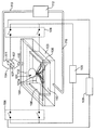
- FIG. 1 is a configuration diagram of a plant growth promoting device according to the first embodiment of the present invention.
- the configuration of the plant growth promoting device will be described below.
- the plant growth promoting apparatus includes at least a container 104, a power source 105, a pair of growth promoting electrodes 106, a pair of sterilizing electrodes 107, and a switch 108.
- the root 101 a of the plant 101 exists in the culture solution 103 of the container 104 containing the culture solution 103 through the panel 102.
- a pair of growth promoting electrodes 106 connectable to the short pulse voltage application power source 105 are provided in the container 104 in order to apply an electric field for promoting plant growth by a short pulse voltage application power source 105 as an example of an electric field application power source. It is provided so as to sandwich the root 101a of the plant 101.
- a growth promoting electric field area 110 is formed between the pair of growth promoting electrodes 106, and the root 101 a of the plant 101 is located in the growth promoting electric field area 110.
- a pair of sterilization electrodes 107 connectable to the short pulse voltage application power source 105 are placed in the container 104. It is provided so as to be interposed between them.
- a sterilization electric field area 111 is formed between the pair of sterilization electrodes 107, but the root 101 a of the plant 101 is not located in the sterilization electric field area 111.
- the pair of sterilization electrodes 107 are installed in the container 104. However, as long as the culture solution 103 can be sterilized, the pair of sterilization electrodes 107 may not necessarily be disposed in the container 104.
- the pair of growth promoting electrodes 106 and the pair of sterilizing electrodes 107 are connected to the short pulse voltage application power source 105 through the switch 108, respectively.
- one electrode (left electrode) of the pair of growth promoting electrodes 106 and one electrode (left electrode) of the pair of sterilization electrodes 107 are one (left side).
- the first switch 108 is interposed, and is connected to the positive electrode of the short pulse voltage application power source 105.
- the other electrode (right electrode) of the pair of growth promoting electrodes 106 and the other electrode (right electrode) of the pair of sterilization electrodes 107 are interposed with the other (right) second switch 108.
- the short pulse voltage application power source 105 is connected to the negative electrode.
- the control device 109 is connected to the first and second switches 108 and the short pulse voltage application power source 105. Therefore, the control device 109 switches and controls the first and second switches 108 to switch the connection between the pair of growth promoting electrodes 106 and the pair of sterilizing electrodes 107 with respect to the short pulse voltage application power source 105.
- the control device 109 controls to switch between the plant growth promotion operation and the sterilization operation and perform the sterilization operation outside the time during which the plant growth promotion operation is performed.
- a root pulse 101a of the plant 101 exists in the growth promotion electric field area 110 formed between the pair of growth promotion electrodes 106.
- a short pulse voltage of about 400 nanoseconds is set to about 1 Hz. Is applied at a repetition frequency of about 100 to 1000 shots.
- a voltage is applied to the sterilization electric field area 111 formed between the pair of sterilization electrodes 107 with a short pulse of 5 microseconds or less in which water is not electrolyzed.
- the pulse width that does not cause water electrolysis is about 2 to 3 microseconds when it is defined as the time to hold a voltage of 50% or more from the voltage peak value. It is managed by the control device 109 as microseconds or less.
- the water in the culture medium 103 is sterilized. It can be controlled by the control device 109 so that the nutrient solution component due to electrolysis does not change.
- the suitable pulse width is about 400 nanoseconds, and the plant growth promotion operation can be performed by applying a voltage of 5 microseconds or less.
- the pair of sterilization electrodes 107 is always disposed at a position where the root 101a of the plant 101 does not enter the sterilization electric field area 111.
- two first and second switches 108 are arranged, one each for a pair of growth promoting electrodes 106 and a pair of sterilizing electrodes 107.
- the number of switches 108 can be halved.
- the first switch (the left switch in FIG. 1) 108 to which the high voltage is applied by the short pulse voltage application power source 105 is eliminated, and the pair of growth promoting electrodes 106 and the pair of sterilizing electrodes 107 are connected.
- the switch 108 can be reduced in size by short-circuiting and performing connection control only by the second switch 108 (the right switch in FIG. 1) that is grounded by the short pulse voltage application power source 105.
- the applied voltage value of the short pulse voltage applying power source 105 and the pair are set within a range where the electric field strength of the growth promoting electric field area 110 between the pair of growth promoting electrodes 106 is 0.1 to 1.5 kV / cm.
- the applied voltage value of the short pulse voltage application power source 105 and the distance between the pair of sterilization electrodes 107 so that the electric field strength of the sterilization electric field area 111 between the pair of sterilization electrodes 107 is 10 kV / cm or more.
- the short pulse voltage application power supply 105 is shared by the growth promotion operation and the sterilization operation, when the pulse width of the applied voltage is the same between the growth promotion operation and the sterilization operation, the resistance value of the load is set to the growth promotion operation. (For example, if the difference in load resistance between the growth promotion operation and the sterilization operation is within an allowable error range of ⁇ 10%, the growth promotion operation and the sterilization operation are matched. Is efficient).
- the discharge curve is determined by the CR characteristic of the capacitor of the pulse voltage application power source 105 and the resistance of the load.
- the same power source 105 can be used by switching between the first and second switches 108 in the growth promotion operation and the sterilization operation. Can be shared and miniaturized, and the equipment cost can be reduced. Furthermore, according to the said plant growth promotion apparatus, a growth promotion operation
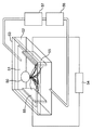
- FIG. 2 is a configuration diagram of the plant growth promoting apparatus according to the second embodiment of the present invention.
- the plant growth promoting apparatus of FIG. 2 is similar to the plant growth promoting apparatus of the first embodiment, except for a circulation device 112 such as a pump, a culture solution recovery pipe 116, a culture solution supply pipe 113, and a culture solution supply unit 114. And further.
- the culture solution recovery pipe 116 connects the container 104 and the circulation device 112 and discharges the culture solution 103 from the container 104 to the circulation device 112 for recovery.
- the culture solution supply pipe 113 connects the circulation device 112 and the culture solution supply unit 114, and supplies the culture solution 103 from the circulation device 112 to the culture solution supply unit 114.
- the culture solution supply unit 114 is disposed at the tip of the culture solution supply pipe 113 on the container side, and a pair of sterilization electrodes 107 are disposed therein so that the lower end opening faces the upper surface of the container 104. .
- the culture solution 103 is supplied from the culture solution supply pipe 113 via the culture solution supply unit 114 in the form of the supply culture solution water flow 115 to the container 104, and the culture solution recovery pipe 116 is supplied from the container 104. After that, the culture solution 103 is returned to the circulation device 112. At this time, the lower end position of the opening of the culture liquid supply unit 114 is set higher than the liquid level of the culture liquid 103 in the container 104. Further, a pair of sterilization electrodes 107 are arranged in the culture solution supply unit 114.
- the sterilization electric field area 111 between the pair of sterilization electrodes 107 is located above the root 101a of the plant 101, and thus the root 101a of the plant 101 does not enter the sterilization electric field area 111. . Furthermore, the culture solution 103 immediately after sterilization can be supplied to the container 104.
- the arrangement or the surface area of the electrodes 106 and 107 is different from each other in advance, so that By applying the same pulse voltage to each of the electrodes 106 and 107, the operation switching between the growth promotion operation and the sterilization operation can be performed by the switch 108. If the ratio between the distance between the electrodes 106 and 107 and the surface area is constant, the same pulse voltage can be applied even if the arrangement or surface area of the electrodes 106 and 107 changes.
- the circulating culture solution is supplied from a position higher than the liquid level of the culture solution 103, and a pair of sterilization electrodes 107 are provided at the end of the supply port.
- the culture solution 103 can be supplied.
- the circulating culture solution is supplied from a position higher than the liquid level of the culture solution 103, and the pair of sterilization electrodes 107 are provided at the supply port, thereby sterilizing.
- the supply of the culture solution 103 immediately after is possible with a simple configuration.
- the same voltage can be applied with the same power source in the growth promotion operation and the sterilization operation, and the power supply member can be used by switching with a switch. Downsizing, equipment costs can be reduced, the cultivation period in hydroponics can be shortened, plant cultivation costs can be reduced, and the introduction of growth promotion technology by electrical stimulation to hydroponic cultivation can be accelerated. It can contribute to solving global food problems.
Landscapes
- Life Sciences & Earth Sciences (AREA)
- Environmental Sciences (AREA)
- Biodiversity & Conservation Biology (AREA)
- Botany (AREA)
- Ecology (AREA)
- Forests & Forestry (AREA)
- Hydroponics (AREA)
Abstract
電圧ピーク値から50%以上の電圧を保持する時間が5マイクロ秒以下の短パルス電圧を印加できる電源(105)と、電源に対する一対の成長促進用電極(106)と一対の殺菌用電極(107)との接続を切り替えるスイッチ(108)を有し、成長促進用電極間には植物(101)の根(101a)が存在し、殺菌用電極間には植物の根が存在しない。
Description
本発明は、水耕栽培で植物の根に電界を与えて成長促進を行う植物成長促進装置に関するものであり、成長促進用の電界印加と殺菌用の電界印加との両立により、必要な電源を小型化することで、植物を育成するコストの低減を実現する技術に関するものである。
水耕栽培による植物育成は、昨今の食糧問題解決のため、重要な技術となっている。水耕栽培による植物育成は、工場等の管理された空間で制御可能であるが、普及のためには、育成期間の短縮及び設備償却費など運転ランニングコストの低減によって、植物を育成するコストを低減することが必須となる。さらに、水耕栽培では、管理された空間ではあるが、養液を循環させて使用するケースが多く、有害な菌又はアオコなどの発生を抑制するために、殺菌装置を導入することが多い。
育成期間短縮のために、水耕栽培で用いている培養液を介して、植物の根に電気刺激を与えることにより、成長を促進する装置が知られている(例えば、非特許文献1参照)。また、殺菌装置としては、紫外線、オゾン、又は光触媒などを用いた装置が用いられている。図3は、従来の技術を組み合わせて、植物の水耕栽培で、成長促進のための電気刺激と殺菌とを実現する装置を示す図である。図3において、植物50が配置されているパネル51を、培養液52の入った栽培容器53に入れ、電源54から出力されている平行平板電極55の間で電界を行い、培養液52を介して植物50の根に電気刺激を与え、植物成長促進を行っている。一方で、循環装置56を用いて、培養液52を循環するとき、殺菌装置57を循環経路に設置し、殺菌装置57で殺菌済みの培養液52を栽培容器53に供給する。
山田雄太、園田剛士、春田大輝、王斗艶、浪平隆男、秋山秀典、谷口雅彦「植物工場への応用を目指したパルス電界によるレタスの生育制御」 電気学会基礎・材料・共通部門大会の抄録集、平成27年3月、p.325
水耕栽培で、図3に示すように、植物の根に電界を与えて成長促進を行う装置と殺菌装置とをそれぞれ設置することは、設備コストが高くなり、植物育成コストの上昇に繋がる。さらに、従来の殺菌装置では、オゾン及び光触媒は共に酸化する力が強く、培養液の組成が変化するため、別途、培養液の管理及び調整が必要となる。具体的には、マンガン又は鉄が酸化マンガン又は酸化鉄として析出する。
本発明は、前記従来の課題を解決するもので、成長促進用電界印加と殺菌用電界印加との両立により、必要な電源を小型化し、さらに培養液の組成を変化させること無く成長促進と殺菌とが可能である植物成長促進装置を提供することを目的とする。
上記目的を達成するために、本発明の1つの態様にかかる植物成長促進装置は、
植物を栽培する培養液と前記植物の根を収容する容器と、
電界を印加する電源と、
前記容器内の前記培養液内に配置されかつ前記電源と接続されて前記電界を印加可能な一対の成長促進用電極と、
前記培養液を挟んで配置されかつ前記電源と接続されて前記電界を印加可能な一対の殺菌用電極と、
前記電源に対する前記成長促進用電極と前記殺菌用電極との接続を切り換えるスイッチとを有し、
前記電源は、電圧ピーク値から50%以上の電圧を保持する時間が5マイクロ秒以下とする短パルスの電圧印加が可能であって、
前記成長促進用電極は、前記電界を印加するエリアに前記植物の前記根が存在する位置に配置され、かつ、
前記殺菌用電極は、前記電界を印加するエリアに前記植物の前記根が存在しない位置に配置されている。
植物を栽培する培養液と前記植物の根を収容する容器と、
電界を印加する電源と、
前記容器内の前記培養液内に配置されかつ前記電源と接続されて前記電界を印加可能な一対の成長促進用電極と、
前記培養液を挟んで配置されかつ前記電源と接続されて前記電界を印加可能な一対の殺菌用電極と、
前記電源に対する前記成長促進用電極と前記殺菌用電極との接続を切り換えるスイッチとを有し、
前記電源は、電圧ピーク値から50%以上の電圧を保持する時間が5マイクロ秒以下とする短パルスの電圧印加が可能であって、
前記成長促進用電極は、前記電界を印加するエリアに前記植物の前記根が存在する位置に配置され、かつ、
前記殺菌用電極は、前記電界を印加するエリアに前記植物の前記根が存在しない位置に配置されている。
したがって、本発明の前記態様にかかる植物成長促進装置によれば、成長促進動作と殺菌動作とで同じ電源をスイッチで切り換えて使用することができるため、電源部材の共通共用化及び小型化が可能となり、設備コストが低減できる。さらに、培養液の組成を変化させること無く成長促進動作と殺菌動作とが可能であり、培養液の管理及び調整コストが削減できる。
本発明のこれらと他の目的と特徴は、添付された図面についての好ましい実施形態に関連した次の記述から明らかになる。この図面においては、
本発明の第1の実施の形態における植物成長促進装置の構成図であり、
本発明の第2の実施の形態における植物成長促進装置の構成図であり、
従来の植物成長促進装置の構成を示す図である。
以下に、本発明の実施の形態について、図面を参照しながら説明する。
(第1の実施の形態)
図1は、本発明の第1の実施の形態にかかる植物成長促進装置の構成図で、以下に、植物成長促進装置の構成を説明する。植物成長促進装置は、少なくとも、容器104と、電源105と、一対の成長促進用電極106と、一対の殺菌用電極107と、スイッチ108とを備えている。
(第1の実施の形態)
図1は、本発明の第1の実施の形態にかかる植物成長促進装置の構成図で、以下に、植物成長促進装置の構成を説明する。植物成長促進装置は、少なくとも、容器104と、電源105と、一対の成長促進用電極106と、一対の殺菌用電極107と、スイッチ108とを備えている。
図1において、植物101の根101aは、パネル102を介して、培養液103が入っている容器104の培養液103内に存在している。電界印加電源の一例としての短パルス電圧印加電源105にて植物成長促進用の電界印加を行うため、短パルス電圧印加電源105に接続可能な一対の成長促進用電極106を、容器104の中で植物101の根101aを挟むように設けている。一対の成長促進用電極106間には成長促進電界エリア110が形成され、成長促進電界エリア110内に植物101の根101aが位置している。合わせて、短パルス電圧印加電源105にて培養液103の殺菌用の電界印加を行うため、短パルス電圧印加電源105に接続可能な一対の殺菌用電極107を容器104の中に培養液103を間に介在させるように設けている。一対の殺菌用電極107間には殺菌電界エリア111が形成されるが、殺菌電界エリア111内には植物101の根101aが位置しないようにしている。図1では、一対の殺菌用電極107を容器104の中に設置しているが、培養液103を殺菌できれば、必ずしも容器104の中に一対の殺菌用電極107を配置しなくても良い。
一対の成長促進用電極106と一対の殺菌用電極107とは、それぞれ、スイッチ108を介在させて、短パルス電圧印加電源105と接続される。具体的には、例えば、図1において、一対の成長促進用電極106の一方の電極(左側電極)と一対の殺菌用電極107の一方の電極(左側電極)とは、一方の(左側の)第1スイッチ108を介在させて、短パルス電圧印加電源105の正極と接続されている。また、一対の成長促進用電極106の他方の電極(右側電極)と一対の殺菌用電極107の他方の電極(右側電極)とは、他方の(右側の)第2スイッチ108を介在させて、短パルス電圧印加電源105の負極と接続されている。
制御装置109は、第1及び第2スイッチ108と短パルス電圧印加電源105とに接続されている。よつて、制御装置109にて第1及び第2スイッチ108を切り替え制御して、短パルス電圧印加電源105に対する、一対の成長促進用電極106と一対の殺菌用電極107との接続を切り替えることにより、植物成長促進動作と殺菌動作とを切り替えて、植物成長促進動作を行っている時間以外で殺菌動作を行うように制御装置109で制御する。
植物成長促進動作は、一対の成長促進用電極106間に形成される成長促進電界エリア110に植物101の根101aが存在する状態で、例えば、400ナノ秒前後の短パルスの電圧を、1Hz程度の繰り返し周波数で100~1000ショット程度、印加する。
殺菌動作は、一対の殺菌用電極107間に形成される殺菌電界エリア111に、水が電気分解しない5マイクロ秒以下の短パルスで電圧印加を行う。水の電気分解を起こさないパルス幅は、電圧ピーク値から50%以上の電圧を保持する時間として定義した場合に2~3マイクロ秒程度であるが、パルス波形ばらつきの影響も加味し、必ず5マイクロ秒以下として制御装置109で管理する。このように、電圧ピーク値から50%以上の電圧を保持する時間が5マイクロ秒以下とする短パルスの電圧印加が可能なように管理することで、殺菌動作時に、培養液103中の水の電気分解による養液成分に変化が無いように制御装置109でコントロールすることができる。
殺菌動作は、一対の殺菌用電極107間に形成される殺菌電界エリア111に、水が電気分解しない5マイクロ秒以下の短パルスで電圧印加を行う。水の電気分解を起こさないパルス幅は、電圧ピーク値から50%以上の電圧を保持する時間として定義した場合に2~3マイクロ秒程度であるが、パルス波形ばらつきの影響も加味し、必ず5マイクロ秒以下として制御装置109で管理する。このように、電圧ピーク値から50%以上の電圧を保持する時間が5マイクロ秒以下とする短パルスの電圧印加が可能なように管理することで、殺菌動作時に、培養液103中の水の電気分解による養液成分に変化が無いように制御装置109でコントロールすることができる。
なお、植物成長促進動作は、前述の通り、好適なパルス幅は400ナノ秒程度であり、5マイクロ秒以下の電圧印加にて可能である。このとき、殺菌電界エリア111に植物101の根101aが入っていると根101aが死んでしまうため、必ず殺菌電界エリア111に植物101の根101aが入らない位置に一対の殺菌用電極107を配置する。なお、図1では、第1及び第2スイッチ108は、一対の成長促進用電極106と一対の殺菌用電極107とで、それぞれ2個ずつ配置しているが、一対の成長促進用電極106と一対の殺菌用電極107との間で、それぞれの距離が充分離れているなど、培養液103による導通の影響が少ない場合は、スイッチ108の数を半分にすることができる。このとき、短パルス電圧印加電源105で高電圧が印加されている側の第1スイッチ(図1では左側のスイッチ)108を無くして一対の成長促進用電極106と一対の殺菌用電極107とを短絡しておき、短パルス電圧印加電源105で接地されている側の第2スイッチ(図1では右側のスイッチ)108のみで接続制御を行うことで、スイッチ108を小型化することができる。
なお、一例として、一対の成長促進用電極106間の成長促進電界エリア110の電界強度が0.1~1.5kV/cmとなる範囲内で、短パルス電圧印加電源105の印加電圧値と一対の成長促進用電極106間の距離とを設定することで、植物成長促進効果を得ることができる。また、一例として、一対の殺菌用電極107間の殺菌電界エリア111の電界強度が10kV/cm以上となるように、短パルス電圧印加電源105の印加電圧値と一対の殺菌用電極107間の距離とを設定することで、殺菌効果を得ることができる。
さらに、短パルス電圧印加電源105は、成長促進動作と殺菌動作とで共用化するため、印加する電圧のパルス幅が成長促進動作と殺菌動作とで同じ場合は、負荷の抵抗値を成長促進動作と殺菌動作とで合わせておく(例えば、成長促進動作と殺菌動作との負荷の抵抗値の差が±10%以内の許容誤差範囲内ならば、成長促進動作と殺菌動作とが合っているとする)と、効率が良い。なお、短パルス電圧印加電源105が、コンデンサの放電を利用して成長促進用のパルス幅を有するパルス波形を有するパルス波形と殺菌用のパルス幅を有するパルス波形とをそれぞれ生成する場合は、短パルス電圧印加電源105のコンデンサと負荷の抵抗のCR特性とで放電カーブが決まる。
なお、一対の成長促進用電極106の電極間距離の値を一対の成長促進用電極106のうちのいずれか一方の表面積の値で割り、かつ成長促進用のパルス幅の値で割った第1の値と、一対の殺菌用電極107の電極間距離値を一対の殺菌用電極107のうちのいずれか一方の表面積の値で割りかつ殺菌用のパルス幅の値で割った第2の値と同じにすることで、成長促進動作と殺菌動作とでパルス幅が異なっても、成長促進動作と殺菌動作とで、パルス幅で正規化した場合で同等のCR特性を得ることができる。このとき、第1の値と第2の値との差がプラスマイナス25%以内の値であるとき、これらの値を同じ値とみなし、ばらつきを制御装置109でコントロールする。ちなみに、成長促進動作と殺菌動作とでパルス幅が全く同じ場合は、短パルス電圧印加電源105に接続される一対の成長促進用電極106と一対の殺菌用電極107とのみを切り換えて、切り換えた一対の電極に対して短パルス電圧印加電源105から同じパルス波形の電圧を印加することで、成長促進動作と殺菌動作とを切り換えることができる。
したがって、前記第1の実施の形態にかかる植物成長促進装置によれば、成長促進動作と殺菌動作とで同じ電源105を第1及び第2スイッチ108で切り換えて使用することができるため、電源部材の共通共用化及び小型化が可能となり、設備コストが低減できる。さらに、前記植物成長促進装置によれば、培養液103の組成を変化させること無く成長促進動作と殺菌動作とが可能であり、培養液103の管理及び調整コストが削減できる。
(第2の実施の形態)
図2は、本発明の第2の実施の第形態における植物成長促進装置の構成図である。
図2の植物成長促進装置は、第1の実施の第形態の植物成長促進装置に、ポンプなどの循環装置112と、培養液回収パイプ116と、培養液供給パイプ113と、培養液供給部114とをさらに備えている。
図2は、本発明の第2の実施の第形態における植物成長促進装置の構成図である。
図2の植物成長促進装置は、第1の実施の第形態の植物成長促進装置に、ポンプなどの循環装置112と、培養液回収パイプ116と、培養液供給パイプ113と、培養液供給部114とをさらに備えている。
培養液回収パイプ116は、容器104と循環装置112とを接続して、容器104から循環装置112に培養液103を排出して回収する。
培養液供給パイプ113は、循環装置112と培養液供給部114とを接続して、循環装置112から培養液供給部114に培養液103を供給する。
培養液供給部114は、培養液供給パイプ113の容器側の先端に配置され、内部に一対の殺菌用電極107を配置して、下端開口が容器104の上面に対向するように配置されている。
よって、循環装置112を用いて、培養液供給パイプ113から培養液供給部114を経由し、供給培養液水流115の形で培養液103を容器104に供給し、容器104から培養液回収パイプ116を経て循環装置112に培養液103を戻す構成となっている。このとき、培養液供給部114の開口の下端位置は、容器104内の培養液103の液面より高い位置にしておく。さらに、一対の殺菌用電極107を培養液供給部114の中に配置しておく。
このような構成によって、一対の殺菌用電極107間の殺菌電界エリア111は、植物101の根101aより上部に位置することになるため、殺菌電界エリア111に植物101の根101aが入ることは無い。さらに、殺菌直後の培養液103を容器104に供給することができる。
以上で説明した第2の実施の形態における植物成長促進装置により、電源105から印加する電圧のパルス幅が同じ場合は、電極106,107の配置又は表面積を予め異ならせて構成するだけで、全く同一のパルス電圧を電極106,107のそれぞれに印加することで、成長促進動作と殺菌動作との動作切り換えがスイッチ108で可能になる。電極106,107の電極間距離と表面積との比が一定であれば、電極106,107の配置又は表面積が変わっても、同一のパルス電圧を印加することができる。成長促進動作と殺菌動作とでパルス幅を変える場合も、電圧電流の挙動は成長促進動作と殺菌動作とで同等となり、電源105としては、電圧は同じで。パルス幅を変えるのみでよい。さらに、培養液103の液面より高い位置から循環培養液を供給し、その供給口端部に一対の殺菌用電極107を設けるといった簡単な構成で、一対の殺菌用電極107で殺菌した直後の培養液103の供給が可能となる。
前記第2の実施の形態にかかる植物成長促進装置によれば、培養液103の液面より高い位置から循環培養液を供給し、その供給口に一対の殺菌用電極107を設けることで、殺菌直後の培養液103の供給が簡単な構成で可能となる。
なお、前記様々な実施形態又は変形例のうちの任意の実施形態又は変形例を適宜組み合わせることにより、それぞれの有する効果を奏するようにすることができる。また、実施形態同士の組み合わせ又は実施例同士の組み合わせ又は実施形態と実施例との組み合わせが可能であると共に、異なる実施形態又は実施例の中の特徴同士の組み合わせも可能である。
本発明の前記態様にかかる植物成長促進装置によれば、成長促進動作と殺菌動作とで、同じ電源で同一電圧を印加し、スイッチで切り換えて使用することができるため、電源部材の共通共用化及び小型化が可能となり、設備コストが低減できて、水耕栽培での育成期間が短縮でき、植物育成コストが低減され、水耕栽培への電気刺激による成長促進技術の導入が加速され、全世界の食料問題解決に寄与することができる。
本発明は、添付図面を参照しながら好ましい実施形態に関連して充分に記載されているが、この技術の熟練した人々にとっては種々の変形又は修正は明白である。そのような変形又は修正は、添付した請求の範囲による本発明の範囲から外れない限りにおいて、その中に含まれると理解されるべきである。
本発明は、添付図面を参照しながら好ましい実施形態に関連して充分に記載されているが、この技術の熟練した人々にとっては種々の変形又は修正は明白である。そのような変形又は修正は、添付した請求の範囲による本発明の範囲から外れない限りにおいて、その中に含まれると理解されるべきである。
Claims (5)
- 植物を栽培する培養液と前記植物の根を収容する容器と、
電界を印加する電源と、
前記容器内の前記培養液内に配置されかつ前記電源と接続されて前記電界を印加可能な一対の成長促進用電極と、
前記培養液を挟んで配置されかつ前記電源と接続されて前記電界を印加可能な一対の殺菌用電極と、
前記電源に対する前記成長促進用電極と前記殺菌用電極との接続を切り換えるスイッチとを有し、
前記電源は、電圧ピーク値から50%以上の電圧を保持する時間が5マイクロ秒以下とする短パルスの電圧印加が可能であって、
前記成長促進用電極は、前記電界を印加するエリアに前記植物の前記根が存在する位置に配置され、かつ、
前記殺菌用電極は、前記電界を印加するエリアに前記植物の前記根が存在しない位置に配置されている、植物成長促進装置。 - 前記一対の成長促進用電極間の電界強度は0.1~1.5kV/cmであって、
前記一対の殺菌用電極間の電界強度が10kV/cm以上である、請求項1記載の植物成長促進装置。 - 前記電源は、コンデンサの放電を利用して成長促進用のパルス幅を有するパルス波形と殺菌用のパルス幅を有するパルス波形とをそれぞれ生成しており、
前記一対の成長促進用電極の電極間距離の値を前記一対の成長促進用電極のうちのいずれか一方の表面積の値で割りかつ前記成長促進用のパルス幅の値で割った値が、前記一対の殺菌用電極の電極間距離値を前記一対の殺菌用電極のうちのいずれか一方の表面積の値で割りかつ前記殺菌用のパルス幅の値で割った値のプラスマイナス25%以内である、請求項1または2に記載の植物成長促進装置。 - 前記培養液を前記容器外に排出したのち、再び、前記容器内に供給するように前記培養液を循環させる循環装置をさらに有し、
前記殺菌用電極は、前記循環装置から前記培養液を前記植物の前記根を入れるための前記容器に前記培養液を供給するまでの経路に設置されており、かつ、前記容器の前記培養液の液面より上部に設置されている、請求項1または2に記載の植物成長促進装置。 - 前記培養液を前記容器外に排出したのち、再び、前記容器内に供給するように前記培養液を循環させる循環装置をさらに有し、
前記殺菌用電極は、前記循環装置から前記培養液を前記植物の前記根を入れるための前記容器に前記培養液を供給するまでの経路に設置されており、かつ、前記容器の前記培養液の液面より上部に設置されている、請求項3に記載の植物成長促進装置。
Applications Claiming Priority (2)
| Application Number | Priority Date | Filing Date | Title |
|---|---|---|---|
| JP2016-200330 | 2016-10-11 | ||
| JP2016200330A JP2018061456A (ja) | 2016-10-11 | 2016-10-11 | 植物成長促進装置 |
Publications (1)
| Publication Number | Publication Date |
|---|---|
| WO2018070097A1 true WO2018070097A1 (ja) | 2018-04-19 |
Family
ID=61905359
Family Applications (1)
| Application Number | Title | Priority Date | Filing Date |
|---|---|---|---|
| PCT/JP2017/028543 Ceased WO2018070097A1 (ja) | 2016-10-11 | 2017-08-07 | 植物成長促進装置 |
Country Status (2)
| Country | Link |
|---|---|
| JP (1) | JP2018061456A (ja) |
| WO (1) | WO2018070097A1 (ja) |
Families Citing this family (3)
| Publication number | Priority date | Publication date | Assignee | Title |
|---|---|---|---|---|
| JP2023013269A (ja) * | 2021-07-15 | 2023-01-26 | アヲハタ株式会社 | 青果物製品の製造方法及び青果物製品 |
| JP7705120B2 (ja) * | 2021-08-30 | 2025-07-09 | 戸田建設株式会社 | 街路樹の生育制御方法 |
| CN119969128A (zh) * | 2025-02-13 | 2025-05-13 | 福建农林大学 | 一种调控植物能量代谢的方法及其应用 |
Citations (4)
| Publication number | Priority date | Publication date | Assignee | Title |
|---|---|---|---|---|
| JPS6356227A (ja) * | 1986-08-26 | 1988-03-10 | 石川島播磨重工業株式会社 | 水栽培装置 |
| US5464456A (en) * | 1993-06-30 | 1995-11-07 | Kertz; M. Glen | Electronic stimulation of plants |
| JP2007259727A (ja) * | 2006-03-28 | 2007-10-11 | Fukuoka Prefecture | 長茎植物の栽培方法及び植物栽培装置 |
| JP2008278796A (ja) * | 2007-05-10 | 2008-11-20 | Tsuchiya Rubber Kk | 植物栽培方法及び植物栽培装置 |
-
2016
- 2016-10-11 JP JP2016200330A patent/JP2018061456A/ja active Pending
-
2017
- 2017-08-07 WO PCT/JP2017/028543 patent/WO2018070097A1/ja not_active Ceased
Patent Citations (4)
| Publication number | Priority date | Publication date | Assignee | Title |
|---|---|---|---|---|
| JPS6356227A (ja) * | 1986-08-26 | 1988-03-10 | 石川島播磨重工業株式会社 | 水栽培装置 |
| US5464456A (en) * | 1993-06-30 | 1995-11-07 | Kertz; M. Glen | Electronic stimulation of plants |
| JP2007259727A (ja) * | 2006-03-28 | 2007-10-11 | Fukuoka Prefecture | 長茎植物の栽培方法及び植物栽培装置 |
| JP2008278796A (ja) * | 2007-05-10 | 2008-11-20 | Tsuchiya Rubber Kk | 植物栽培方法及び植物栽培装置 |
Non-Patent Citations (2)
| Title |
|---|
| NOBUYA HAYASHI ET AL.: "Enhancement of Yield of Harvest using Plasma and Pulsed Power", JOURNAL OF PLASMA AND FUSION RESEARCH, vol. 90, no. 9, pages 541 - 546 * |
| YUTA YAMAMOTO ET AL.: "Shokubutsu Kojo eno Oyo o Mezashita Pulse Denkai ni yoru Lettuce no Seiiku Seigyo", HEISEI 27 NEN ANNUAL CONFERENCE OF FUNDAMENTALS AND MATERIALS SOCIETY IEE JAPAN RONBUNSHU, 17 September 2015 (2015-09-17), pages 325 * |
Also Published As
| Publication number | Publication date |
|---|---|
| JP2018061456A (ja) | 2018-04-19 |
Similar Documents
| Publication | Publication Date | Title |
|---|---|---|
| EP2254664B1 (de) | Plasma-gerät zur selektiven behandlung elektroporierter zellen | |
| US10669169B2 (en) | Plasma activated water | |
| WO2018070097A1 (ja) | 植物成長促進装置 | |
| US20080212624A1 (en) | Dual pulse-width medical laser | |
| EP4670627A3 (en) | Methods and apparatus for selective tissue ablation | |
| CN109661210A (zh) | 不可逆电穿孔设备及其操作方法 | |
| EP2462954A3 (en) | Plasma generation method and apparatus for biocidal and deodorising air treatment | |
| WO2009012803A1 (de) | Verfahren zur ansteurung zumindest eines inverters in einer plasmaleistungsversorgungseinrichtung und plasmaleistungsversorgungseinrichtung | |
| DE102014106797B3 (de) | Verfahren und Vorrichtung zur mobilen Schmerztherapie | |
| CN206673930U (zh) | 一种复合高压脉冲电场、电场灭菌装置 | |
| JP2015216872A (ja) | 植物栽培補助装置、水耕栽培装置、水耕栽培プラント及び植物栽培補助方法 | |
| RU2016127559A (ru) | Система формирования электрических импульсов с использованием емкостной связи | |
| CN106712745B (zh) | 一种复合高压脉冲电场、电场灭菌装置及方法 | |
| WO2019064935A1 (ja) | 除菌水生成装置及び水回り機器 | |
| JP2014229619A (ja) | 単一電源の多極型電界放出装置およびその駆動方法 | |
| KR20140084551A (ko) | 수중 종자 플라즈마 처리 방법 | |
| JP4844488B2 (ja) | 高電圧パルス制御による選択的液体処理方法 | |
| CN114081614A (zh) | 脉冲电场组织消融装置 | |
| RU2012149303A (ru) | Способ электропитания разрядного несимметричного генератора озона | |
| CN112601334B (zh) | 一种紫外线杀菌灯的驱动电路及消毒杀菌设备 | |
| EP4545102A1 (en) | System and method for sterilizing an air volume | |
| TWI584881B (zh) | 液體霧化電路及其裝置 | |
| MX2012001751A (es) | Circuito excitador de electrodo de ionizador de aire. | |
| CN107455159B (zh) | 植物生长促进装置及方法 | |
| JP6799822B2 (ja) | 植物栽培装置及び方法 |
Legal Events
| Date | Code | Title | Description |
|---|---|---|---|
| 121 | Ep: the epo has been informed by wipo that ep was designated in this application |
Ref document number: 17860681 Country of ref document: EP Kind code of ref document: A1 |
|
| NENP | Non-entry into the national phase |
Ref country code: DE |
|
| 122 | Ep: pct application non-entry in european phase |
Ref document number: 17860681 Country of ref document: EP Kind code of ref document: A1 |