WO2018069961A1 - Air conditioning apparatus - Google Patents
Air conditioning apparatus Download PDFInfo
- Publication number
- WO2018069961A1 WO2018069961A1 PCT/JP2016/080112 JP2016080112W WO2018069961A1 WO 2018069961 A1 WO2018069961 A1 WO 2018069961A1 JP 2016080112 W JP2016080112 W JP 2016080112W WO 2018069961 A1 WO2018069961 A1 WO 2018069961A1
- Authority
- WO
- WIPO (PCT)
- Prior art keywords
- human body
- temperature
- air
- age group
- unit
- Prior art date
Links
Images


Classifications
-
- F—MECHANICAL ENGINEERING; LIGHTING; HEATING; WEAPONS; BLASTING
- F24—HEATING; RANGES; VENTILATING
- F24F—AIR-CONDITIONING; AIR-HUMIDIFICATION; VENTILATION; USE OF AIR CURRENTS FOR SCREENING
- F24F11/00—Control or safety arrangements
- F24F11/70—Control systems characterised by their outputs; Constructional details thereof
- F24F11/72—Control systems characterised by their outputs; Constructional details thereof for controlling the supply of treated air, e.g. its pressure
- F24F11/79—Control systems characterised by their outputs; Constructional details thereof for controlling the supply of treated air, e.g. its pressure for controlling the direction of the supplied air
-
- F—MECHANICAL ENGINEERING; LIGHTING; HEATING; WEAPONS; BLASTING
- F24—HEATING; RANGES; VENTILATING
- F24F—AIR-CONDITIONING; AIR-HUMIDIFICATION; VENTILATION; USE OF AIR CURRENTS FOR SCREENING
- F24F1/00—Room units for air-conditioning, e.g. separate or self-contained units or units receiving primary air from a central station
- F24F1/0007—Indoor units, e.g. fan coil units
- F24F1/0043—Indoor units, e.g. fan coil units characterised by mounting arrangements
- F24F1/0047—Indoor units, e.g. fan coil units characterised by mounting arrangements mounted in the ceiling or at the ceiling
-
- F—MECHANICAL ENGINEERING; LIGHTING; HEATING; WEAPONS; BLASTING
- F24—HEATING; RANGES; VENTILATING
- F24F—AIR-CONDITIONING; AIR-HUMIDIFICATION; VENTILATION; USE OF AIR CURRENTS FOR SCREENING
- F24F1/00—Room units for air-conditioning, e.g. separate or self-contained units or units receiving primary air from a central station
- F24F1/0007—Indoor units, e.g. fan coil units
- F24F1/0043—Indoor units, e.g. fan coil units characterised by mounting arrangements
- F24F1/0057—Indoor units, e.g. fan coil units characterised by mounting arrangements mounted in or on a wall
-
- F—MECHANICAL ENGINEERING; LIGHTING; HEATING; WEAPONS; BLASTING
- F24—HEATING; RANGES; VENTILATING
- F24F—AIR-CONDITIONING; AIR-HUMIDIFICATION; VENTILATION; USE OF AIR CURRENTS FOR SCREENING
- F24F1/00—Room units for air-conditioning, e.g. separate or self-contained units or units receiving primary air from a central station
- F24F1/0007—Indoor units, e.g. fan coil units
- F24F1/0059—Indoor units, e.g. fan coil units characterised by heat exchangers
- F24F1/0063—Indoor units, e.g. fan coil units characterised by heat exchangers by the mounting or arrangement of the heat exchangers
-
- F—MECHANICAL ENGINEERING; LIGHTING; HEATING; WEAPONS; BLASTING
- F24—HEATING; RANGES; VENTILATING
- F24F—AIR-CONDITIONING; AIR-HUMIDIFICATION; VENTILATION; USE OF AIR CURRENTS FOR SCREENING
- F24F2110/00—Control inputs relating to air properties
- F24F2110/10—Temperature
-
- F—MECHANICAL ENGINEERING; LIGHTING; HEATING; WEAPONS; BLASTING
- F24—HEATING; RANGES; VENTILATING
- F24F—AIR-CONDITIONING; AIR-HUMIDIFICATION; VENTILATION; USE OF AIR CURRENTS FOR SCREENING
- F24F2120/00—Control inputs relating to users or occupants
- F24F2120/10—Occupancy
- F24F2120/12—Position of occupants
-
- F—MECHANICAL ENGINEERING; LIGHTING; HEATING; WEAPONS; BLASTING
- F24—HEATING; RANGES; VENTILATING
- F24F—AIR-CONDITIONING; AIR-HUMIDIFICATION; VENTILATION; USE OF AIR CURRENTS FOR SCREENING
- F24F2140/00—Control inputs relating to system states
- F24F2140/10—Pressure
- F24F2140/12—Heat-exchange fluid pressure
Definitions
- This invention relates to an air conditioner.
- an air conditioner equipped with a situation recognition device which has an air conditioning control unit that realizes air conditioning control based on the situation recognition result identified by the situation recognition means is known.
- a foot position detecting means for detecting the foot position of the person and a head position detecting means for detecting the head position of the person are provided, and the foot position information obtained by the foot position detecting means and the head
- a device using height estimation means for detecting the height of a person using head position information obtained by the part position detection means is known (for example, see Patent Document 1).
- the conventional air conditioner disclosed in Patent Document 1 performs air conditioning control based on the result estimated by the height estimating means, for example, for a child with a short height, the wind from the air conditioner is It is possible not to directly apply air conditioning with a weak air flow, but to directly apply the air from the air conditioner to an adult with a sufficiently high height to perform air conditioning with a strong air flow.
- the purpose of the air conditioner is to be able to achieve appropriate conditioned air blowing according to the age group of the user, and thus improve the comfort of the user, regardless of the height of the user. Is to provide.
- the housing formed with the suction port and the air outlet, and the air that is provided inside the housing and exchanges heat with the air sucked from the suction port to generate conditioned air.
- a heat exchanger and a blower mechanism that is provided in the housing and generates an air flow that sucks air from the suction port and blows out conditioned air from the blower outlet, and can change a wind direction of the conditioned air blown out from the blower outlet;
- a temperature detecting means for detecting a surface temperature within a preset detection range; and a control device for controlling the air blowing mechanism in accordance with a detection result of the temperature detecting means, the temperature detecting means detecting
- the wind direction of the conditioned air is set to the direction of the human body, and the wind direction of the conditioned air is maintained in the direction of the human body until the surface temperature of the human body reaches a reference temperature.
- the reference temperature is configured to be set in accordance with the variation of the human
- the air-conditioning apparatus it is possible to realize appropriate conditioned air blowing according to the age group of the user without being influenced by the height of the user, and thus improve the user's comfort. There is an effect that can be.
- FIG. 1 to 10 relate to Embodiment 1 of the present invention.
- FIG. 1 is an external perspective view of an air conditioner
- FIG. 2 is a longitudinal sectional view of the air conditioner
- FIG. 3 is a human body included in the air conditioner.
- FIG. 4 is a diagram illustrating the detection range of the human body sensor in the depth direction of the air conditioning apparatus
- FIG. 5 is a diagram illustrating the detection range of the human body sensor in the horizontal direction of the air conditioning apparatus
- FIG. 6 is a block diagram showing the configuration of the control system of the air conditioner
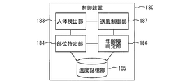
- FIG. 7 is a block diagram showing the functional configuration of the control device of the air conditioner
- FIG. 8 is a graph showing the foot temperature of the human body during the heating operation of the air conditioner.
- FIG. 1 is an external perspective view of an air conditioner
- FIG. 2 is a longitudinal sectional view of the air conditioner
- FIG. 3 is a human body included in the air conditioner.
- FIG. 4 is a diagram illustrating the detection range of the human body sensor in
- FIG. 9 is a diagram showing an example of a change with time
- FIG. 9 is a diagram showing an example of a change with time of the head temperature of the human body during the heating operation of the air conditioner
- FIG. 10 is a flowchart showing the air flow control during the heating operation of the air conditioner It is.
- the air conditioner 100 according to Embodiment 1 of the present invention is, for example, an indoor unit of an air conditioner. Therefore, the air conditioning apparatus 100 is installed on an indoor wall surface or ceiling surface. Here, it is assumed that the air conditioner 100 is installed on an indoor wall surface.
- the air conditioner 100 includes a housing 110.
- the casing 110 of the air conditioner 100 is formed in a substantially rectangular parallelepiped shape that is horizontally long and has a smooth curved surface from the front surface to the lower surface.
- a suction port 111 is formed on the upper surface of the housing 110.
- the suction port 111 is an opening for taking air into the housing 110 from the outside.
- An air outlet 112 is formed in the lower front portion of the housing 110.
- the air outlet 112 is an opening for discharging air from the inside of the housing 110 to the outside.
- the front upper portion of the housing 110 is covered with a front panel 113.
- the upper and lower wind direction plates 131, 132, 141, 142 are provided at the air outlet 112. These up-and-down wind direction plates are for adjusting the blowing angle in the vertical direction of the air blown out from the blow-out port 112.
- the up-and-down wind direction plates are respectively installed on the front side and the back side toward the front of the air conditioner 100. Further, the up and down wind direction plates on the near side and the far side are respectively divided into left and right. That is, the front side vertical wind direction plate is divided into a left front side vertical wind direction plate 131 on the left side and a right front side vertical wind direction plate 132 on the right side facing the front of the air conditioner 100. Further, the back side up / down wind direction plate is divided into a left back side up / down wind direction plate 141 and a right back side up / down wind direction plate 142 facing the front of the air conditioner 100.
- each vertical wind direction plate is divided into right and left is approximately the center in the longitudinal direction (left and right direction of the air outlet 112) toward the front of the air conditioner 100.
- a slight gap is formed between the left front side vertical wind direction plate 131 and the right front side vertical wind direction plate 132.
- a slight gap is also formed between the left back side vertical wind direction plate 141 and the right back side vertical wind direction plate 142.
- the left front side vertical wind direction plate 131, the right front side vertical wind direction plate 132, the left back side vertical wind direction plate 141, and the right back side vertical wind direction plate 142 are plate-like members that are elongated in the left and right direction of the air outlet 112, respectively. Further, these up-and-down wind direction plates 131, 132, 141, 142 are each curved so that a cross section perpendicular to the longitudinal direction is arcuate.
- the vertical wind direction plates 131, 132, 141, 142 are each attached to the housing 110 via support arms (not shown). Each support arm is rotatably attached to the housing 110. Each support arm rotates with respect to the housing 110 so that the direction of the vertical wind direction plate can be changed. And the air conditioning apparatus 100 can change the ventilation direction up and down by changing the direction of an up-and-down wind direction board.
- Each support arm of the vertical wind direction plate is provided so that the angle can be adjusted by driving the stepping motor for the vertical wind direction plate.
- the directions of the left front side vertical wind direction plate 131 and the left back side vertical wind direction plate 141 are changed by the left vertical wind direction plate stepping motor 161 here.
- the directions of the right front side vertical wind direction plate 132 and the right back side vertical wind direction plate 142 are changed by the stepping motor 162 for the right vertical wind direction plate.
- the vertical blowing angle (air blowing direction) of the air blown from the left side of the air outlet 112 and the vertical blowing angle (air blowing direction) of the air blown from the right side of the air outlet 112 are adjusted separately. be able to.
- the left-side up / down wind direction plate stepping motor 161 and the right-side up / down wind direction plate stepping motor 162 are not shown in FIGS. 1 and 2.
- Left and right wind direction plates 150 are provided on the back side of the up and down wind direction plates 131, 132, 141, and 142 at the air outlet 112.
- the left and right wind direction plates 150 are for adjusting the blowing angle in the left and right direction of the air blown from the blower outlet 112.
- the left and right wind direction plates 150 are configured by a plurality of plates arranged in the longitudinal direction (left and right direction of the air outlet 112) toward the front of the air conditioner 100.
- the left and right wind direction plates 150 are attached so that the angle can be adjusted by driving a stepping motor 163 for left and right wind direction plates (not shown in FIGS. 1 and 2), similarly to the upper and lower wind direction plates 131, 132, 141, 142. Yes.
- a heat exchanger 121 is installed on the leeward side of the suction port 111 in the air passage.
- the heat exchanger 121 exchanges heat with the air flowing through the air passage to heat or cool the air flowing through the air passage. Whether the air is heated or cooled depends on whether the air-conditioning apparatus 100 is in a heating operation or a cooling operation. Specifically, the heat exchanger 121 heats the air during the heating operation. On the other hand, the heat exchanger 121 cools the air during the cooling operation.
- the heat exchanger 121 adjusts the temperature, humidity, and the like of the air by heating or cooling the air flowing through the air passage, and generates conditioned air. In this way, the heat exchanger 121 exchanges heat with the air sucked from the suction port 111 to generate conditioned air. Note that warm air is generated as conditioned air during heating operation, and cold air is generated as conditioned air during cooling operation.
- a blower fan 122 is installed on the leeward side of the heat exchanger 121 in the air path.
- the blower fan 122 is for generating an air flow from the inlet 111 to the outlet 112 in the air passage.
- the blower fan 122, the up / down wind direction plates 131, 132, 141, 142, the left / right wind direction plate 150, the up / down wind direction plate stepping motors 161, 162, and the left / right wind direction plate stepping motor 163 are provided in a blower mechanism provided in the housing 110. Is configured.
- the air blowing mechanism configured as described above can generate an air flow that sucks air from the suction port 111 and blows out conditioned air from the blower outlet 112, and can change the wind direction of the conditioned air blown from the blower outlet 112.
- a human body sensor 170 is attached to the center of the front surface of the air conditioner 100.
- the mounting position of the human body sensor 170 is not limited to the center of the front surface of the air conditioning apparatus 100.
- the human body sensor 170 may be attached to the left or right end of the housing 110.
- the human body sensor 170 includes, for example, a plurality of infrared sensors (light receiving elements) arranged in the vertical direction.
- the human body sensor 170 includes, for example, eight infrared sensors (light receiving elements).
- Each of these eight infrared sensors is a detection element that can individually perform infrared light reception and temperature detection.
- these infrared sensors (light receiving elements) are arranged in a straight line in the vertical direction inside a cylindrical metal can 171. Accordingly, the human body sensor 170 has a function of detecting the room temperature by dividing it into eight areas having different heights.
- the detection ranges of these eight infrared sensors are set as rectangular areas having the same size as shown in FIG.
- the light distribution viewing angle of one infrared sensor is set such that, for example, the vertical light distribution viewing angle in the vertical direction is set to 7 °, and the horizontal light distribution viewing angle in the horizontal direction is set to 8 °.
- the light distribution viewing angle 173 of the whole human body sensor 170 that combines the light distribution viewing angles of the respective infrared sensors is set as an elongated area in the vertical direction.
- the light distribution viewing angle (detection range) of each infrared sensor does not need to have the same shape and the same size.
- specific values of the vertical light distribution viewing angle and the horizontal light distribution viewing angle are not limited to the above-described examples.
- the number of infrared sensors (light receiving elements) is not limited to eight, and the human body sensor 170 includes an arbitrary number of infrared sensors (light receiving elements) of 7 or less or 9 or more. Also good.
- the human body sensor 170 can change the direction of a plurality of infrared sensors arranged vertically by a sensor stepping motor 172 (not shown in FIGS. 1 and 2) to the left and right within a preset angle range. By doing in this way, each of the plurality of infrared sensors arranged vertically is scanned in the left-right direction, and within a preset detection range (hereinafter referred to as “temperature detection target range”) in front of the air conditioner 100. The surface temperature can be detected.
- the human body sensor 170 scans the temperature detection target range and acquires the surface temperature distribution (thermal image) in the range without contact. That is, the human body sensor 170 constitutes temperature detecting means for detecting a surface temperature within a preset detection range.
- the detection result of the human body sensor 170 that is, the surface temperature distribution (thermal image) data acquired by the human body sensor 170 is processed by the control device 180 or the like to include a person in the room from a temperature difference with the background, for example.
- the presence / absence and position of the heat source, the surface temperature of the human body, the body part of the human body (exposed and unexposed portions of the skin, head, etc.), etc. can be detected.
- the temperature of the human body in the room can also be obtained.
- the human body with exposed skin is more likely to detect the sensible temperature.
- the detection accuracy of the human body sensor 170 increases as the number of pixels of the light receiving element used in the human body sensor 170 increases. Specifically, for example, if a light receiving element having 30 or more pixels is used, the position of a person in the room and the distance from the human body sensor 170 to the person can be accurately detected.
- the human body sensor 170 detects the temperature of the temperature detection target while scanning the temperature detection target range left and right.
- the left and right are the left and right when viewed from the air conditioner 100 side.
- the direction of the human body sensor 170 is moved left and right by the sensor stepping motor 172, and the rotation of the sensor stepping motor 172 (that is, the human body sensor).
- (Rotation in the direction of 170) is stopped for a certain time at every certain angle.
- the fixed angle at this time is set to 1 to 5 °, for example. Further, the fixed time at this time is, for example, 0.1 to 0.2 seconds.
- the change of the orientation of the human body sensor 170 is stopped, it waits for a time shorter than the predetermined time (0.1 to 0.2 seconds), and the detection results (thermal results) of the 8 human body sensors 170 are detected.
- Image data may be a time shorter than the predetermined time (0.1 to 0.2 seconds), and the detection results (thermal results) of the 8 human body sensors 170 are
- the sensor stepping motor 172 is rotated again by the predetermined angle and stopped again, and the detection result (thermal image data) of the human body sensor 170 is acquired by the same operation.
- the detection results of the human body sensor 170 are obtained at, for example, 90 to 100 locations in the left-right direction within the detection range.
- the thermal image data (temperature distribution data) of the temperature detection target range can be obtained from the acquired detection result of the human body sensor 170.
- FIG. 4 is a diagram for explaining the detection range of the human body sensor 170 in the depth direction as viewed from the air conditioning apparatus 100.
- This FIG. 4 has shown the state which looked at the room
- the air conditioner 100 is installed at a height of about 1800 mm, and the state where the distance from the air conditioner 100 to the human body is about 3600 mm is illustrated.
- the detection range of the human body sensor 170 is divided into a plurality of regions equal to the number of infrared sensors (light receiving elements) (here, 8) in the depth direction. That is, the indoor space is divided into eight regions corresponding to the light distribution viewing angles of the respective light receiving elements in the depth direction. The width of each divided area is set according to the vertical spread angle of the light distribution viewing angle.
- the lowermost light receiving element of the human body sensor 170 detects the human body in the area on the near side closest to the air conditioner 100.
- the light receiving element on the upper side of the human body sensor 170 is configured to detect a human body in a far region.
- FIG. 5 is a diagram for explaining the detection range of the human body sensor 170 in the left-right direction as viewed from the air conditioning apparatus 100.
- This FIG. 5 has shown the state which looked at the room
- the detection range of the human body sensor 170 is divided into a plurality of regions with respect to the predetermined angle when the human body sensor 170 is rotated by the sensor stepping motor 172 in the left-right direction.
- FIG. 5 illustrates a case where the detection range in the left-right direction of the human body sensor 170 is set to about 90 °.
- the detection range in the left-right direction of the human body sensor 170 is not limited to this angle.
- the human body sensor 170 can be completely rotated by the sensor stepping motor 172, and the detection range is set to 360 °. May be.
- the human body sensor 170 may be swung in the vertical direction by another stepping motor or the like. By making the orientation of the human body sensor 170 changeable in the vertical direction, detailed thermal image data can be acquired not only in the horizontal direction but also in the vertical direction.
- the human body sensor 170 may be configured to use an infrared sensor and another detection device in combination.
- the position, shape, and distance to the human body may be detected using a camera, an ultrasonic sensor, or the like. That is, as the human body sensor 170, in addition to the infrared sensor, for example, an ultrasonic sensor capable of detecting an object may be further provided. By doing in this way, the detection accuracy of the position and distance of the human body by the human body sensor 170 can be improved. Or it is good also as a structure which detects the position of the human body in the depth direction (front-back direction) seen from the air conditioning apparatus 100 using the pyroelectric sensor using a Fresnel lens.
- the air conditioning apparatus 100 includes a control device 180 and an operation display unit 190.
- the control device 180 is configured by an electric circuit including, for example, a microcomputer.
- the control device 180 includes a processor 181 and a memory 182.
- the memory 182 stores a control program.
- the processor 181 reads and executes a program stored in the memory 182.
- the control device 180 executes a preset process to control the operation of the air conditioner 100.
- the processor 181 executes the program stored in the memory 182 to realize the functions of the human body detection unit 183, the region specifying unit 184, the age group determination unit 186, and the air blow control unit 187, which will be described later.
- a sensor system including a human body sensor 170 and the like is connected to the input side of the control device 180.
- various actuators including a blower fan 122, a stepping motor 161 for the left and right wind direction plate, a stepping motor 162 for the right and left wind direction plate, a stepping motor 163 for the left and right wind direction plate, and a sensor stepping motor 172. Is connected.
- the operation display unit 190 is used for the user to input various setting values and also displays various information to the user.
- the operation display unit 190 is, for example, a remote controller (remote controller).
- the operation display unit 190 is connected to the control device 180 so as to be able to communicate with each other.
- the user can perform power ON / OFF, switching between heating operation and cooling operation, setting of temperature, wind direction, air volume, and the like.
- the operation display unit 190 includes, for example, a liquid crystal display that displays various types of information. On the liquid crystal display of the operation display unit, for example, setting contents such as an operation mode, temperature, wind direction, and air volume are displayed.
- the control device 180 drives each actuator based on the input from the sensor system and the operation display unit 190, and controls the operation of the air conditioner 100.
- the control executed by the control device 180 includes, for example, control such as cooling operation, heating operation, air blowing operation, and scanning operation of the human body sensor 170. That is, the control device 180 performs control of the air blowing mechanism according to the detection result of the human body sensor 170 which is a temperature detection unit, for example.
- the control device 180 includes a human body detection unit 183, a part specification unit 184, a temperature storage unit 185, an age group determination unit 186, and a ventilation control unit 187.
- the human body detection unit 183 detects a human body existing within the temperature detection target range of the human body sensor 170 based on the detection result of the human body sensor 170 which is a temperature detection unit.
- the human body can be detected using, for example, the shape, distribution (relative positional relationship), area, and the like of each region where the surface temperature detected by the human body sensor 170 is equal to or higher than a preset reference temperature.
- the reference temperature at this time is specifically set to, for example, 30 ° C. in consideration of the human body temperature.
- the part specifying unit 184 specifies the determination part of the human body detected by the human body detecting unit 183.
- the determination part is a part of the human body that is used by the age group determination unit 186 to determine the age group of the human body. Which part of the human body is determined as the determination part is specified in advance.
- the determination part may be specified by first specifying the entire shape of the human body, and then specifying the determination part from the entire shape of the human body, or specifying the determination part directly. .
- the part specifying unit 184 When specifying the entire shape of the human body, the part specifying unit 184 first specifies a region where the human body detected by the human body detecting unit 183 exists.
- the region where the human body exists can be specified using, for example, the shape, distribution (relative positional relationship), area, and relative magnitude relationship of the temperature of each region where the surface temperature is equal to or higher than a certain temperature.
- region will also be specified, ie, the shape of a human body can be specified.
- the part specifying unit 184 may specify the entire area where the human body exists, or the area where the human body exists may be individually specified for each part of the human body. You may specify. In the case of individually specifying the region existing for each part of the human body, the part specifying unit 184, for example, for each part of the human head, chest, arm, upper leg, lower leg, hand and foot, Each of the areas where the Here, the “hand” refers to a portion on the tip side of the wrist. Further, the “foot” here refers to a portion on the tip side of the ankle.
- the part specifying unit 184 particularly sets a part where the surface temperature detected by the human body sensor 170 is equal to or higher than a preset temperature as a region where at least one of the head, chest, and abdomen of the human body exists. It may be specified. Moreover, when specifying the region where each part of the human body exists, the part specifying unit 184 may specify the temperature, position, and clothing state of each part.
- the “clothing state” is a state relating to whether the skin of the part is covered with clothes or the like or exposed.
- the part specifying unit 184 determines whether the human body is based on the detection result of the infrared sensor and the detection result of the ultrasonic sensor. It is preferable to identify the region where the detected human body exists.
- the uppermost light receiving element detects the head of the human body.
- the head is exposed and the skin temperature is higher than other parts of the human body, for example, a skin temperature of 30 ° C. or higher. Therefore, the part specifying unit 184 can identify the region to which the head of the human body belongs based on the thermal image data acquired by the human body sensor 170. More specifically, the part specifying unit 184 analyzes thermal image data acquired by the uppermost light receiving element by scanning in the horizontal direction. And when the shape of the heat source whose detected temperature is 30 ° C. or more in the horizontal direction matches the shape of the human head that is stored in advance (for example, a circular shape), this heat source is specified as the head.
- the second light receiving element from the top detects the chest and arms of the human body.
- the chest is almost always covered with clothes and the skin is rarely exposed.
- the arm portion may or may not be exposed to the skin.
- the part specifying unit 184 can determine whether or not the arm part is exposed based on the surface temperature detected by the human body sensor 170. Specifically, when the skin of the arm portion is exposed, a skin temperature equivalent to or slightly lower than that of the head is detected at a position corresponding to the arm portion. This is because the arm may be cooler than the head, and in this case, the temperature of the arm is detected as a temperature lower than the head.
- the third light receiving element from the top detects the upper leg of the human body.
- the upper leg is covered with clothes.
- the surface temperature of clothes is detected at a position corresponding to the upper leg.
- the surface temperature of the garment is lower than the temperature of the skin.
- a temperature equal to or lower than that of the head is detected at the position of the hand.
- the hand may be colder than the head. In this case, a temperature lower than that of the head is detected at the position of the hand.
- the fourth light receiving element from the top detects the lower leg of the human body.
- the human body wears clothing such as socks
- the surface temperature of the clothing is detected at the position of the lower leg.
- the feet are cold, a temperature lower than the surface temperature of the clothing is detected at a position corresponding to the lower leg regardless of whether or not the clothing is worn.
- the part specifying unit 184 determines the shape of the region above a certain temperature in advance. By comparing and comparing the shape of each part stored with each other, an area where each part exists is specified.
- the age group determination unit 186 determines the age group of the human body based on the surface temperature of the determination part of the human body.
- the determination part of the human body is a part specified by the part specifying unit 184 as the determination part among the parts of the human body.
- the surface temperature of the determination part of the human body the surface temperature detected by the human body sensor 170 as temperature detecting means is used.
- the age group determination part 186 determines the age group of the said human body based on the variation
- the age group determined by the age group determination unit 186 includes at least adults and children.
- an age group other than an adult and a child for example, an elderly person can be considered.
- an example in which the age group is two adults and children will be described.
- FIG. 8 shows an example of temporal changes in the temperature of the feet of adults and children after the start of heating operation.
- FIG. 9 is an example of the time change of the temperature of the head of an adult and a child after heating operation start.
- FIG. 8 and FIG. 9 as the heating operation is started and the room temperature rises, the temperature of both feet and heads of adults and children rises. At this time, as shown in FIG. 9, there is not much difference in the amount of temperature change with the passage of time between the adult and the child, as shown in FIG.
- thermoregulatory functions are more susceptible to ambient temperature than adults.
- the temperature of the foot is susceptible to the temperature of the floor with which the foot is in contact, and the floor temperature is lower than the room temperature at the start of heating operation, so the child is more susceptible to the floor temperature below this room temperature. It can be considered that the temperature of the foot of a person is less likely to rise than the temperature of the foot of an adult.
- the human foot is designated in advance as the determination part. That is, the part specifying unit 184 specifies the part of the human foot detected by the human body detecting unit 183.
- the age group determination unit 186 determines the age group of the human body based on the surface temperature of the human foot detected by the human body sensor 170. More specifically, the age group determination unit 186 determines the age group of the human body based on the amount of change per unit time in the surface temperature of the foot, which is the determination site.
- the age group determination unit 186 determines that the age group of the human body is a child when the amount of change in the surface temperature of the human foot (determination site) per unit time is equal to or less than a preset reference value ⁇ . judge. On the other hand, the age group determination unit 186 determines that the age group of the human body is an adult when the change amount per unit time of the surface temperature of the foot of the human body is not less than the reference value ⁇ .
- the control device 180 includes a temperature storage unit 185 in order to obtain a change amount per unit time of the surface temperature of the determination part.
- the temperature storage unit 185 stores the value of the surface temperature of the determination part (here, the foot) of the human body detected by the human body sensor 170 for each unit time.
- the age group determination unit 186 calculates the amount of change per unit time of the surface temperature of the determination part using the value of the surface temperature of the determination part stored in the temperature storage unit 185. Then, the age group determination unit 186 determines whether the human body is an adult or a child by comparing the amount of change in the surface temperature of the calculated determination site per unit time with the reference value ⁇ described above. Do.
- a foot is designated as a determination part.
- the part of the human body as the determination part is not limited to the foot.
- the age group determination unit 186 determines whether the age group of the human body is a child depending on whether the absolute value of the amount of change in the surface temperature of the human foot per unit time is equal to or less than the reference value ⁇ described above. Or whether it is an adult.
- the air blowing control unit 187 controls the air blowing mechanism described above based on the age group of the human body determined by the age group determining unit 186 as described above.
- the specific contents of the control of the air blowing mechanism based on the determination result of the age group of the human body will be described next for each of the heating operation and the cooling operation.
- control of the ventilation mechanism based on the determination result of the human body age group described below may be performed only in one of the heating operation and the cooling operation, or may be performed in both.
- the blower control unit 187 controls the blower mechanism so that the wind direction of the conditioned air is directed to the position of the human body. . Further, when the temperature of the human body detected by the human body sensor 170 during the heating operation is equal to or higher than the heating reference temperature, the air blowing control unit 187 sets the air blowing mechanism so that the conditioned air direction is different from the position of the human body. Control and perform the so-called “human blow”.
- the air blowing mechanism It is desirable to control the air blowing mechanism so that the distance between the human body and the air flow of conditioned air is 0.3 m or more when performing this “human air blowing”. It is preferable to set the distance so that the distance between the conditioned air flow and the human body is 0.3 m or more even at the closest position. According to this setting, even if the airflow of the conditioned air is diffused to some extent, it is possible to sufficiently suppress the airflow from hitting the human body.
- the “heating reference temperature” used as a reference in such air blowing control is a temperature that is a criterion for determining whether or not the human body needs to be warmed.
- the “heating reference temperature” is set according to the age group determined by the age group determining unit 186. That is, in the first embodiment of the present invention, specifically, the adult heating reference temperature and the child heating reference temperature can be set as the “heating reference temperature”.
- the adult heating reference temperature is a reference value used when the age group determined by the age group determination unit 186 is an adult.
- the child heating reference temperature is a reference value used when the age group determined by the age group determination unit 186 is a child.
- each of the adult heating reference temperature and the child heating reference temperature is, for example, when the part specifying unit 184 specifies each part of the human body individually, It is calculated using the temperature of all or part of each part of the arm, upper leg, lower leg, hand and foot. At this time, for each temperature of each part, a product obtained by multiplying a preset weighting coefficient may be used for the calculation. In this case, the weighting coefficient is set in advance and stored in advance in the memory 182 of the control device 180.
- the temperature of each part used for calculating the heating reference temperature for example, the surface temperature of each part detected by the human body sensor 170 is used.
- the human body part and weighting coefficient used for calculating the adult heating reference temperature may be different from the human body part and weighting coefficient used for calculating the child heating reference temperature.
- the temperature of each part of the human body is used to calculate the adult heating reference temperature
- each part of the upper body of the human body (the human head, chest, arms and hands) is used to calculate the child heating reference temperature. ) Temperature may be used.
- the air blowing control unit 187 sets the heating reference temperature according to the age group determined by the age group determining unit 186, and controls the air blowing mechanism. That is, the air blowing control unit 187 controls the air blowing mechanism described above based on the age group of the human body determined by the age group determining unit 186.
- the air blow control unit 187 determines whether the human body temperature corresponds to each age group.
- the air blowing mechanism may be controlled so that the wind direction of the conditioned air is directed to the position of the human body at an intermediate point between two or more human bodies lower than the heating reference temperature.
- the plurality of human bodies mentioned here include both combinations of the same age group (adults and adults, children and children) and combinations of those of different age groups (adults and children).
- the air blow control unit 187 controls the air blow mechanism so that the air direction of the conditioned air is directed to the position of the human body when the temperature of the human body detected by the human body sensor 170 is equal to or higher than the cooling reference temperature during the cooling operation. . Further, when the temperature of the human body detected by the human body sensor 170 during the cooling operation is lower than the cooling reference temperature, the air blowing control unit 187 sets the air blowing mechanism so that the conditioned air is directed in a direction different from the position of the human body. Control and perform the so-called “human blow”. At this time, as in the case of the heating operation, it is desirable to control the air blowing mechanism so that the distance between the human body and the air flow of the conditioned air is 0.3 m or more.
- the “cooling reference temperature” of the human body is a temperature that is a criterion for determining whether or not the human body needs to be cooled.
- the “cooling reference temperature” is set according to the age group determined by the age group determining unit 186. That is, in the first embodiment of the present invention, specifically, two adult cooling reference temperatures and child cooling reference temperatures can be set as the “cooling reference temperature”.
- the adult cooling reference temperature is a reference value used when the age group determined by the age group determination unit 186 is an adult.
- the child cooling reference temperature is a reference value used when the age group determined by the age group determination unit 186 is a child.
- the adult cooling reference temperature and the child cooling reference temperature are set in the same manner as the adult heating reference temperature and the child heating reference temperature. That is, each of the adult cooling reference temperature and the child cooling reference temperature uses, for example, the temperature of all or part of the human head, chest, arms, upper legs, lower legs, hands and feet. Calculated. At this time, for each temperature of each part, a product obtained by multiplying a preset weighting coefficient may be used for the calculation.
- the human body part and weighting coefficient used for calculating the adult cooling reference temperature may be different from the human body part and weighting coefficient used for calculating the child cooling reference temperature.
- the air blowing control unit 187 sets the cooling reference temperature according to the age group determined by the age group determining unit 186, and controls the air blowing mechanism. That is, the air blowing control unit 187 controls the air blowing mechanism described above based on the age group of the human body determined by the age group determining unit 186.
- step S1 the human body sensor 170 starts detecting the surface temperature, and the human body detection unit 183 includes the human body sensor 170. The detection of the human body based on the detection result is started.
- step S ⁇ b> 2 the human body detection unit 183 confirms whether or not a human body has been detected based on the detection result of the human body sensor 170. If no human body is detected, the process returns to step S1. On the other hand, when the human body detection unit 183 detects a human body, the process proceeds to step S3.
- step S3 the air blowing control unit 187 controls the air blowing mechanism so as to blow conditioned air toward the position of the human body detected by the human body detecting unit 183. In addition, since it is heating operation here, the conditioned air sent is warm air. After step S3, the process proceeds to step S4.
- step S4 first, the part specifying unit 184 specifies a region where the human body detected by the human body detecting unit 183 is present. And the part specific
- part of a human body is a leg
- the part specifying unit 184 specifies the determination part of the human body, that is, the foot
- the human body sensor 170 detects the temperature of the foot (determination site) of the human body at regular time intervals, for example, every unit time.
- the temperature of the human foot (determination part) detected by the human body sensor 170 is stored in the temperature storage unit 185 as time series data.
- step S5 first, the age group determination unit 186 calculates the amount of change in foot temperature per unit time based on the time-series data of the temperature of the human foot (determination part) stored in the temperature storage unit 185. To do. Next, the age group determination unit 186 checks whether or not the calculated amount of change in the foot temperature of the human body per unit time is equal to or less than the reference value ⁇ described above. When the amount of change in the foot temperature of the human body per unit time is equal to or less than the reference value ⁇ , the process proceeds to step S6.
- step S6 the age group determination unit 186 determines that the age group of the human body is a child. And it progresses to step S7, First, the ventilation control part 187 calculates the specific value of the child heating reference temperature, and sets the calculated child heating reference temperature as heating reference temperature. Next, the air blow control unit 187 confirms whether or not the temperature of the human body is equal to or higher than the child heating reference temperature. If the temperature of the human body is not equal to or higher than the child heating reference temperature, the process proceeds to step S8.
- step S8 the blowing control unit 187 controls the blowing mechanism so as to blow conditioned air toward the position of the human body. After step S8, the process returns to step S7, and the air blowing toward the human body is continued until the temperature of the human body becomes equal to or higher than the child heating reference temperature.
- step S9 the age group determination unit 186 determines that the age group of the human body is an adult. And it progresses to step S10, and the ventilation control part 187 calculates the concrete value of adult heating reference temperature first, and sets the calculated adult heating reference temperature as heating reference temperature.
- the air blow control unit 187 confirms whether or not the temperature of the human body is equal to or higher than the adult heating reference temperature. If the temperature of the human body is not equal to or higher than the adult heating reference temperature, the process proceeds to step S11.
- step S11 the air blowing control unit 187 controls the air blowing mechanism so as to blow conditioned air toward the position of the human body. After step S11, the process returns to step S10, and the air blowing toward the human body is continued until the temperature of the human body becomes equal to or higher than the adult heating reference temperature.
- step S7 if the temperature of the human body is equal to or higher than the child heating reference temperature, the process proceeds to step S12. Moreover, also when the temperature of the said human body becomes more than adult heating reference temperature by step S10, it progresses to step S12.
- step S ⁇ b> 12 the air blowing control unit 187 performs so-called human air blowing. That is, the air blowing mechanism is controlled so as to blow conditioned air in a direction different from the position of the human body detected by the human body sensor 170. And although a series of operation
- the heating operation is almost the same in the cooling operation. That is, the operation when the air-conditioning apparatus 100 starts the cooling operation by the user's operation on the operation display unit 190 or the like is the heating shown in FIG. 8 for steps S1 to S6, S8, S9, S11, and S12. Same as driving.
- step S7 of the cooling operation first, the air blow control unit 187 calculates a specific value of the child cooling reference temperature, and sets the calculated child cooling reference temperature as the cooling reference temperature. Next, the air blow control unit 187 confirms whether or not the temperature of the human body is equal to or higher than the child cooling reference temperature. If the temperature of the human body is equal to or higher than the child cooling reference temperature, the process proceeds to step S8. On the other hand, if the temperature of the human body is not equal to or higher than the child cooling reference temperature, the process proceeds to step S12.
- step S10 of the cooling operation the air blowing control unit 187 first calculates a specific value of the adult cooling reference temperature, and sets the calculated adult cooling reference temperature as the cooling reference temperature. Next, the air blow control unit 187 confirms whether or not the temperature of the human body is equal to or higher than the adult cooling reference temperature. If the temperature of the human body is equal to or higher than the adult cooling reference temperature, the process proceeds to step S11. On the other hand, if the temperature of the human body is not equal to or higher than the adult cooling reference temperature, the process proceeds to step S12.
- the air-conditioning apparatus 100 configured as described above includes a human body detection unit 183 that detects a human body based on the surface temperature detected by the human body sensor 170, and a part that specifies a predetermined determination site of the detected human body.
- An age group determination unit 186 that determines the age group of the human body based on the surface temperature of the determination part of the human body based on the specifying unit 184, and a ventilation control unit that controls the blower mechanism based on the determined age group of the human body 187.
- the conditioned air can be appropriately blown according to the age group of the user.
- the user's comfort can be improved.
- the human body sensor 170 such as an infrared sensor without taking an image of the user's face and using an image recognition technique or the like. Therefore, the cost required for manufacturing the product can be kept low.
- the thermal sensation may be different even in the same environment.
- children are hotter than adults (especially women), and if there are children and adult women at the same time in a heated room, adult women feel cold at the temperature set for the child, conversely Children often feel hot at preset temperatures tailored to adult women.
- the reference temperature for performing “human ventilation” can be changed based on the age group of the human body determined by the age group determination unit 186. Therefore, even if a child and an adult with the same height are in the same room, the conditioned air can be appropriately blown to the child and the adult, thereby improving the user's comfort. it can.
- an adult misidentified as a child can be prevented from feeling cold due to the wind even though it has not reached a sufficiently warm state.
- cooling operation it is possible to prevent a child erroneously determined as an adult from being windshielded and feeling hot even though the child has not reached a sufficiently cool state.
- the air direction of the conditioned air can be switched to a direction other than the human body to shift to heating of the entire room.
- the effect of reducing noise can be obtained by reducing the air volume.
- the age group of the human body is determined based on the amount of change in the surface temperature of the human body per unit time, and the heating reference temperature or the cooling reference temperature is set according to the determined age group. It was a thing. However, regarding this point, in the first embodiment, the heating reference temperature or the cooling reference temperature may be set directly from the amount of change in the surface temperature of the human body without determining the age group of the human body.
- the air conditioner 100 specifies a human body from the distribution of the surface temperature detected by the human body sensor 170 that is a temperature detection means
- the air direction of the conditioned air is set to the direction of the human body
- the surface temperature of the human body is You may make it hold
- the heating reference temperature or the cooling reference temperature which is the reference temperature at this time, is set according to the amount of change in the surface temperature of the human body.
- control device 180 stores in advance a table of the heating reference temperature or the cooling reference temperature corresponding to the amount of change per unit time of the surface temperature of the human body. And the control apparatus 180 sets the heating reference temperature or the cooling reference temperature from the detection result of the human body sensor 170 with reference to the content of this table.
- the determination result of the age group determination unit may be displayed on the operation display unit 190. That is, the air conditioning apparatus 100 may include a display unit that displays the determination result of the age group determination unit. By doing in this way, the user can know how the user's own age group is determined by the air conditioning apparatus 100 by confirming the display of the operation display unit 190.
- FIG. FIG. 11 relates to Embodiment 2 of the present invention, and is a flowchart showing air blow control during heating operation of the air conditioner.
- Embodiment 2 described here is a configuration in which the determination of the age group of the human body based on the height of the human body is used in combination with the configuration of the first embodiment described above. That is, the height of the human body detected by the human body sensor 170 is detected, and the age group determination unit 186 first determines the age group based on the height of the human body. As described in the first embodiment, the age group is determined based on the temperature of the determination part of the human body.
- the air conditioning apparatus according to the second embodiment will be described focusing on the differences from the first embodiment.
- the basic configuration of the air conditioner 100 according to the second embodiment is the same as that shown in FIGS. 1 to 6 shown in the first embodiment.
- the structure of the control apparatus 180 with which the air conditioning apparatus 100 which concerns on Embodiment 2 is provided is fundamentally the same as the structure of Embodiment 1 shown in FIG.
- the function of the age group determination unit 186 is different from that of the first embodiment. That is, in the second embodiment, the age group determination unit 186 first detects the height of the human body based on the shape of the human body specified by the region specifying unit 184. Then, the age group determination unit 186 determines the age group of the human body based on the detected height of the human body.
- the age group determination unit 186 determines that the age group of the human body is a child when the detected height of the human body is equal to or less than the height reference value.
- the height reference value is set in advance after individual consideration according to the setting place, application, and the like of the air conditioner 100. Specific examples of the height reference value include a value such as 130 cm.
- the age group determination unit 186 determines the age group of the human body based on the surface temperature of the determination part of the human body.
- the determination of the age group of the human body based on the surface temperature of the determination part of the human body is exactly the same as in the first embodiment. Other configurations are the same as those in the first embodiment, and detailed description thereof is omitted.
- steps S1 to S3 are the same as steps S1 to S3 of the flowchart of FIG. And in this Embodiment 2, it progresses to step S21 after step S3.
- step S21 the age group determination unit 186 detects the height of the human body based on the shape of the human body specified by the region specifying unit 184. After step S21, the process proceeds to step S22.
- step S22 the age group determination unit 186 checks whether or not the height of the human body detected in step S21 is equal to or less than the height reference value. If the height of the human body is less than or equal to the height reference value, the process proceeds to step S6, and the age group determination unit 186 determines that the age group of the human body is a child.
- step S4 the age group determination unit 186 determines the age group based on the temperature of the determination part of the human body. Steps S4 to S12 are the same as steps S4 to S12 in the flowchart of FIG.
- the air conditioning apparatus 100 configured as described above first attempts to determine whether or not the age group of the human body is a child based on the height of the human body. If it can be determined that the age group of the human body is a child based on the height of the human body, the age group of the human body is assumed to be a child at that time. On the other hand, when it cannot be determined that the age group of the human body is a child based on the height of the human body, the age group is determined based on the temperature of the determination part of the human body as described in the first embodiment.
- the human body sensor 170 detects a plurality of human bodies, it is possible to expect a significant improvement in the processing speed of the control device 180 by reducing the processing load on the control device 180.
- the height reference value is set to a value that can be determined to be a child, and first, it is determined whether or not the age group of the human body is a child based on the height of the human body.
- the height reference value may be set to a value that can be determined to be an adult, and first, based on the height of the human body, it may be determined whether or not the age group of the human body is an adult. .
- the height reference value is a value such as 170 cm.
- the age group determination part 186 determines with the age group of the said human body being an adult, when the height of the detected human body is more than a height reference value. On the other hand, when the detected height of the human body is less than the height reference value, the age group determination unit 186 determines the age group of the human body based on the surface temperature of the determination part of the human body.
- FIG. 12 and 13 relate to Embodiment 3 of the present invention.
- FIG. 12 is a diagram showing an example of changes in the foot temperature of the human body during the heating operation of the air conditioner
- FIG. 13 is the heating of the air conditioner. It is a flowchart which shows the ventilation control at the time of a driving
- Embodiment 1 and Embodiment 2 described above determine the age group of the human body based on the amount of change per unit time in the surface temperature of the determination part of the human body.
- the third embodiment described here is based on the amount of change in the surface temperature of the determination part of the human body when the room temperature changes by the unit temperature in the configuration of the first or second embodiment described above.
- the age group of the human body is determined.
- the air conditioner according to the third embodiment will be described focusing on differences from the first embodiment, taking an example configured based on the first embodiment.
- the basic configuration of the air conditioner 100 according to the third embodiment is the same as that shown in FIGS. 1 to 6 shown in the first embodiment.
- the structure of the control apparatus 180 with which the air conditioning apparatus 100 which concerns on Embodiment 3 is provided is fundamentally the same as the structure of Embodiment 1 shown in FIG.
- the function of the age group determination unit 186 is different from that of the first embodiment. That is, in the third embodiment, the age group determination unit 186 is configured so that the age group determination unit 186 is based on the amount of change in the surface temperature of the determination part of the human body when the room temperature changes by the unit temperature. Determine the age group.
- FIG. 12 shows an example of the relationship between the room temperature after the start of heating operation and the temperature of the feet of adults and children. As the heating operation starts and the room temperature rises, the temperature of the feet of adults and children rises. In this case, as shown in FIG. 12, the inventor compared the amount of change in foot temperature in the case of a child when the room temperature changes by a unit temperature in comparison with the amount of change in foot temperature in the case of an adult. I found it smaller.
- the human foot is designated in advance as the determination part. That is, the part specifying unit 184 specifies the part of the human foot detected by the human body detecting unit 183. Then, the age group determination unit 186 determines the age group of the human body based on the amount of change in the surface temperature of the foot, which is the determination site, per unit time when the room temperature changes by the unit temperature.
- the age group determination unit 186 when the change in the surface temperature of the human foot (determination site) when the room temperature changes by the unit temperature is equal to or less than a preset reference value ⁇ , Determine that the human body is a child. On the other hand, if the amount of change in the surface temperature of the human foot when the room temperature changes by the unit temperature is not less than the reference value ⁇ , the age group determination unit 186 determines that the age group of the human body is an adult. .
- the air conditioner 100 in order to obtain the amount of change in the surface temperature of the human foot (determination site) when the room temperature changes by the unit temperature, the air conditioner 100 includes room temperature detection means for detecting the room temperature. ing.
- a temperature sensor may be provided in the casing 110, the suction port 111, and the like of the air conditioner 100.
- a temperature sensor may be provided in a location different from the casing 110 of the air conditioner 100, and the temperature sensor and the air conditioner 100 may be connected to be communicable.
- the temperature of the indoor floor surface or wall surface detected by the infrared sensor included in the human body sensor 170 may be used as the room temperature.
- the human body sensor 170 serves as both a temperature detection unit that detects a surface temperature within a preset detection range and a room temperature detection unit that detects a room temperature.
- the temperature storage unit 185 stores the value of the surface temperature of the determination part (here, the foot) of the human body detected by the human body sensor 170 and the value of the room temperature detected by the room temperature detection means for a certain period of time.
- the age group determination unit 186 calculates the amount of change in the surface temperature of the determination part when the room temperature changes by the unit temperature, using the surface temperature value and the room temperature value of the determination part stored in the temperature storage unit 185. To do. Then, the age group determination unit 186 determines whether the human body is an adult or a child by comparing the calculated amount of change in the surface temperature of the determination site with the reference value ⁇ described above.
- Other configurations are the same as those in the first embodiment, and detailed description thereof is omitted.
- steps S1 to S4 are the same as steps S1 to S4 of the flowchart of FIG. And in this Embodiment 3, it progresses to step S31 after step S4.
- step S31 the age group determination unit 186, the age group determination unit 186, based on the temperature of the human foot (determination site) stored in the temperature storage unit 185 and the time-series data of the room temperature, the room temperature is the unit temperature only. The amount of change in foot temperature when changing is calculated.
- the age group determination unit 186 checks whether or not the calculated change in the foot temperature of the human body is equal to or less than the reference value ⁇ described above. When the amount of change in the human foot temperature is equal to or less than the reference value ⁇ , the process proceeds to step S6. On the other hand, if the amount of change in the foot temperature of the human body is not less than or equal to the reference value ⁇ , the process proceeds to step S9. Steps S6 to S12 are the same as steps S6 to S12 in the flowchart of FIG.
- the air conditioning apparatus 100 configured as described above is configured to determine the age group of the human body based on the amount of change in the surface temperature of the determination part of the human body when the room temperature changes by the unit temperature. .
- the change amount per unit time of the surface temperature of the determination part of the human body is used as in the first embodiment, the temperature change amount per unit time is small when the heating and cooling set temperatures are close to the room temperature. Therefore, there is a possibility that the situation is not suitable for determination of the age group.
- the amount of change in the surface temperature of the determination part of the human body when the room temperature changes by the unit temperature this is not the case, and in many cases the age group based on the surface temperature of the determination part Judgment can be made.
- the air when blowing air toward the human body, the air may be directed toward a specific part of the human body instead of the entire human body. Specifically, for example, the air may be intensively directed toward the feet of the human body. In addition, for example, the air may be intensively directed toward the human hand.
- the air flow control may be performed using temperature information such as room temperature, temperature at the air inlet 111 of the air conditioner, temperature at the air outlet 112, and the like. At this time, a change amount or a change rate per unit time of the temperature information can also be used.
- the present invention can be used for an air conditioner equipped with a blowing mechanism capable of changing the wind direction of the conditioned air blown out from the outlet.
- Air conditioning apparatus 110 Case 111 Inlet port 112 Outlet port 113 Front panel 121 Heat exchanger 122 Blower fan 131 Left front side up-and-down air direction plate 132 Right front side up-and-down air direction plate 141 Left back side up-and-down air direction plate 142 Right back side up-and-down air direction plate 150 Left and right wind direction plate 161 Step motor for left and right wind direction plate 162 Step motor for right and left wind direction plate 163 Step motor for left and right wind direction plate 170 Human body sensor 171 Metal can 172 Sensor stepping motor 173 Light distribution viewing angle 180 Controller 181 Processor 182 Memory 183 Human body detection unit 184 Site identification unit 185 Temperature storage unit 186 Age group determination unit 187 Air blow control unit 190 Operation display unit
Landscapes
- Engineering & Computer Science (AREA)
- Chemical & Material Sciences (AREA)
- Combustion & Propulsion (AREA)
- Mechanical Engineering (AREA)
- General Engineering & Computer Science (AREA)
- Physics & Mathematics (AREA)
- Thermal Sciences (AREA)
- Air Conditioning Control Device (AREA)
Abstract
Provided is an air conditioning apparatus that is capable of appropriately blowing conditioned air in accordance with the age group of a user, without being affected by the height of the user. Therefore, this air conditioning apparatus is provided with: an air blowing mechanism that is provided in a housing, generates air flow by sucking in air from an intake port and blowing conditioned air from a blowing port, and is capable of changing the wind direction of the conditioned air blowing from the blowing port; a temperature detection means that detects the surface temperature within a preset detection range; and a control device that controls the air blowing mechanism in accordance with a detection result of the temperature detection means, wherein, in the case where a human body has been identified from the distribution of the surface temperature detected by the temperature detection means, the wind direction of the conditioned air is set so as to be oriented toward the human body, and the wind direction of the conditioned air is maintained so as to be oriented toward the human body until the surface temperature of the human body reaches a reference temperature. The reference temperature is set in accordance with the amount of change in the surface temperature of the human body.
Description
この発明は、空気調和装置に関するものである。
This invention relates to an air conditioner.
従来においては、状況認識装置を搭載した空気調和機であって、状況認識手段が識別した状況認識結果に基づいて、空調制御を実現する空調制御部を有するものが知られている。そして、状況認識手段として、人物の足元位置を検出する足元位置検出手段と、人物の頭部位置を検出する頭部位置検出手段と、を備え、足元位置検出手段で求めた足元位置情報と頭部位置検出手段で求めた頭部位置情報を利用して、人物の身長を検出する身長推定手段を用いるものが知られている(例えば、特許文献1参照)。
Conventionally, an air conditioner equipped with a situation recognition device, which has an air conditioning control unit that realizes air conditioning control based on the situation recognition result identified by the situation recognition means is known. Then, as the situation recognition means, a foot position detecting means for detecting the foot position of the person and a head position detecting means for detecting the head position of the person are provided, and the foot position information obtained by the foot position detecting means and the head A device using height estimation means for detecting the height of a person using head position information obtained by the part position detection means is known (for example, see Patent Document 1).
特許文献1に示された従来における空気調和装置は、身長推定手段で推定した結果を基に、空調制御を行なうことで、例えば、身長の低い子どもに対しては、空気調和装置からの風を直接当てず、また、弱めの風量による空調を行ない、身長が十分に高い大人に対しては、空気調和装置からの風を直接当て、強めの風量による空調を行なうといったことが可能である。
The conventional air conditioner disclosed in Patent Document 1 performs air conditioning control based on the result estimated by the height estimating means, for example, for a child with a short height, the wind from the air conditioner is It is possible not to directly apply air conditioning with a weak air flow, but to directly apply the air from the air conditioner to an adult with a sufficiently high height to perform air conditioning with a strong air flow.
しかしながら、特許文献1に示された従来における空気調和装置においては、身長のみにより大人であるか子どもであるか、すなわち年齢層を判定しているため、例えば、身長の高い子ども又は身長の低い大人について誤った年齢層の判定をしてしまい、年齢層に応じた適切な送風制御を行うことができない。
However, in the conventional air-conditioning apparatus disclosed in Patent Document 1, since it is determined whether it is an adult or a child, that is, an age group, based on height alone, for example, a tall child or a short adult Therefore, it is impossible to perform appropriate airflow control according to the age group.
この発明は、このような課題を解決するためになされた。その目的は、使用者の身長に左右されることなく、使用者の年齢層に応じた適切な調和空気の送風を実現でき、ひいては使用者の快適感の向上を図ることができる空気調和装置を提供することである。
This invention has been made to solve such problems. The purpose of the air conditioner is to be able to achieve appropriate conditioned air blowing according to the age group of the user, and thus improve the comfort of the user, regardless of the height of the user. Is to provide.
この発明に係る空気調和装置においては、吸込口及び吹出口が形成された筐体と、前記筐体の内部に設けられ、前記吸込口から吸い込まれた空気と熱交換して調和空気を生成する熱交換器と、前記筐体に設けられ、前記吸込口から空気を吸い込み前記吹出口から調和空気を吹き出す空気流を生成するとともに、前記吹出口から吹き出す調和空気の風向を変更可能な送風機構と、予め設定された検出範囲内の表面温度を検出する温度検出手段と、前記温度検出手段の検出結果に応じて、前記送風機構を制御する制御装置と、を備え、前記温度検出手段が検出した表面温度の分布から人体を特定した場合に、前記調和空気の風向を前記人体の方向に設定し、前記人体の表面温度が基準温度になるまで前記調和空気の風向を前記人体の方向に保持し、前記基準温度は、前記人体の表面温度の変化量に応じて設定される構成とする。
In the air conditioning apparatus according to the present invention, the housing formed with the suction port and the air outlet, and the air that is provided inside the housing and exchanges heat with the air sucked from the suction port to generate conditioned air. A heat exchanger and a blower mechanism that is provided in the housing and generates an air flow that sucks air from the suction port and blows out conditioned air from the blower outlet, and can change a wind direction of the conditioned air blown out from the blower outlet; A temperature detecting means for detecting a surface temperature within a preset detection range; and a control device for controlling the air blowing mechanism in accordance with a detection result of the temperature detecting means, the temperature detecting means detecting When the human body is specified from the surface temperature distribution, the wind direction of the conditioned air is set to the direction of the human body, and the wind direction of the conditioned air is maintained in the direction of the human body until the surface temperature of the human body reaches a reference temperature. The reference temperature is configured to be set in accordance with the variation of the human body surface temperature.
この発明に係る空気調和装置においては、使用者の身長に左右されることなく、使用者の年齢層に応じた適切な調和空気の送風を実現でき、ひいては使用者の快適感の向上を図ることができるという効果を奏する。
In the air-conditioning apparatus according to the present invention, it is possible to realize appropriate conditioned air blowing according to the age group of the user without being influenced by the height of the user, and thus improve the user's comfort. There is an effect that can be.
この発明を実施するための形態について添付の図面を参照しながら説明する。各図において、同一又は相当する部分には同一の符号を付して、重複する説明は適宜に簡略化又は省略する。なお、本発明は以下の実施の形態に限定されることなく、本発明の趣旨を逸脱しない範囲で種々変形することが可能である。
DETAILED DESCRIPTION Embodiments for carrying out the present invention will be described with reference to the accompanying drawings. In the drawings, the same or corresponding parts are denoted by the same reference numerals, and overlapping descriptions are simplified or omitted as appropriate. The present invention is not limited to the following embodiments, and various modifications can be made without departing from the spirit of the present invention.
実施の形態1.
図1から図10は、この発明の実施の形態1に係るもので、図1は空気調和装置の外観斜視図、図2は空気調和装置の縦断面図、図3は空気調和装置が備える人体センサの検出範囲を説明する図、図4は空気調和装置の奥行き方向における人体センサの検出範囲を説明する図、図5は空気調和装置の水平方向における人体センサの検出範囲を説明する図、図6は空気調和装置の制御系統の構成を示すブロック図、図7は空気調和装置の制御装置の機能的な構成を示すブロック図、図8は空気調和装置の暖房運転時の人体の足温度の経時変化の一例を示す図、図9は空気調和装置の暖房運転時の人体の頭部温度の経時変化の一例を示す図、図10は空気調和装置の暖房運転時の送風制御を示すフロー図である。 Embodiment 1 FIG.
1 to 10 relate to Embodiment 1 of the present invention. FIG. 1 is an external perspective view of an air conditioner, FIG. 2 is a longitudinal sectional view of the air conditioner, and FIG. 3 is a human body included in the air conditioner. FIG. 4 is a diagram illustrating the detection range of the human body sensor in the depth direction of the air conditioning apparatus, FIG. 5 is a diagram illustrating the detection range of the human body sensor in the horizontal direction of the air conditioning apparatus, and FIG. 6 is a block diagram showing the configuration of the control system of the air conditioner, FIG. 7 is a block diagram showing the functional configuration of the control device of the air conditioner, and FIG. 8 is a graph showing the foot temperature of the human body during the heating operation of the air conditioner. FIG. 9 is a diagram showing an example of a change with time, FIG. 9 is a diagram showing an example of a change with time of the head temperature of the human body during the heating operation of the air conditioner, and FIG. 10 is a flowchart showing the air flow control during the heating operation of the air conditioner It is.
この発明の実施の形態1における空気調和装置100は、例えば、空気調和機の室内機である。したがって、空気調和装置100は、室内の壁面又は天井面に設置されている。ここでは、空気調和装置100は、室内の壁面に設置されているとする。
The air conditioner 100 according to Embodiment 1 of the present invention is, for example, an indoor unit of an air conditioner. Therefore, the air conditioning apparatus 100 is installed on an indoor wall surface or ceiling surface. Here, it is assumed that the air conditioner 100 is installed on an indoor wall surface.
図1及び図2に示すように、空気調和装置100は、筐体110を備えている。空気調和装置100の筐体110は、横長で前面から下面にかけては滑らかな曲面となった略直方体状に形成されている。筐体110の上面部には、吸込口111が形成されている。吸込口111は、外部から筐体110の内部に空気を取り込むための開口である。筐体110の前面下部には、吹出口112が形成されている。吹出口112は、筐体110の内部から外部へと空気を排出するための開口である。筐体110の前面上部は、前面パネル113に覆われている。
As shown in FIGS. 1 and 2, the air conditioner 100 includes a housing 110. The casing 110 of the air conditioner 100 is formed in a substantially rectangular parallelepiped shape that is horizontally long and has a smooth curved surface from the front surface to the lower surface. A suction port 111 is formed on the upper surface of the housing 110. The suction port 111 is an opening for taking air into the housing 110 from the outside. An air outlet 112 is formed in the lower front portion of the housing 110. The air outlet 112 is an opening for discharging air from the inside of the housing 110 to the outside. The front upper portion of the housing 110 is covered with a front panel 113.
吹出口112には、上下風向板131、132、141、142が設けられている。これらの上下風向板は、吹出口112から吹き出す空気の上下方向の吹き出し角度を調整するためのものである。
The upper and lower wind direction plates 131, 132, 141, 142 are provided at the air outlet 112. These up-and-down wind direction plates are for adjusting the blowing angle in the vertical direction of the air blown out from the blow-out port 112.
上下風向板は、空気調和装置100の正面に向かって手前側と奥側とにそれぞれ設置されている。また、手前側と奥側の各上下風向板は、それぞれ左右に分割されている。すなわち、手前側の上下風向板は、空気調和装置100の正面に向かって左側の左手前側上下風向板131と、右側の右手前側上下風向板132とに分割されている。また、奥側の上下風向板は、空気調和装置100の正面に向かって左側の左奥側上下風向板141と、右側の右奥側上下風向板142とに分割されている。
The up-and-down wind direction plates are respectively installed on the front side and the back side toward the front of the air conditioner 100. Further, the up and down wind direction plates on the near side and the far side are respectively divided into left and right. That is, the front side vertical wind direction plate is divided into a left front side vertical wind direction plate 131 on the left side and a right front side vertical wind direction plate 132 on the right side facing the front of the air conditioner 100. Further, the back side up / down wind direction plate is divided into a left back side up / down wind direction plate 141 and a right back side up / down wind direction plate 142 facing the front of the air conditioner 100.
それぞれの上下風向板が左右に分割される位置は、空気調和装置100の正面に向かって長手方向(吹出口112の左右方向)のほぼ中央である。左手前側上下風向板131と右手前側上下風向板132との間には、僅かな隙間が形成されている。同様に、左奥側上下風向板141と右奥側上下風向板142との間にも、僅かな隙間が形成されている。
The position where each vertical wind direction plate is divided into right and left is approximately the center in the longitudinal direction (left and right direction of the air outlet 112) toward the front of the air conditioner 100. A slight gap is formed between the left front side vertical wind direction plate 131 and the right front side vertical wind direction plate 132. Similarly, a slight gap is also formed between the left back side vertical wind direction plate 141 and the right back side vertical wind direction plate 142.
左手前側上下風向板131、右手前側上下風向板132、左奥側上下風向板141及び右奥側上下風向板142は、それぞれ、吹出口112の左右方向に細長く延びた板状の部材である。また、これらの上下風向板131、132、141、142は、それぞれ、長手方向に垂直な断面が円弧状となるように湾曲している。
The left front side vertical wind direction plate 131, the right front side vertical wind direction plate 132, the left back side vertical wind direction plate 141, and the right back side vertical wind direction plate 142 are plate-like members that are elongated in the left and right direction of the air outlet 112, respectively. Further, these up-and-down wind direction plates 131, 132, 141, 142 are each curved so that a cross section perpendicular to the longitudinal direction is arcuate.
上下風向板131、132、141、142は、それぞれが図示しない支持腕を介して筐体110に取り付けられている。それぞれの支持腕は筐体110に対して回転可能に取り付けられている。各支持腕が筐体110に対して回転することで、それぞれの上下風向板の向きを変えることができるようになっている。そして、上下風向板の向きを変えることで、空気調和装置100は、送風方向を上下に変更可能である。
The vertical wind direction plates 131, 132, 141, 142 are each attached to the housing 110 via support arms (not shown). Each support arm is rotatably attached to the housing 110. Each support arm rotates with respect to the housing 110 so that the direction of the vertical wind direction plate can be changed. And the air conditioning apparatus 100 can change the ventilation direction up and down by changing the direction of an up-and-down wind direction board.
上下風向板のそれぞれの支持腕は、上下風向板用ステッピングモータの駆動により角度を調節できるように設けられている。具体的にここでは、左手前側上下風向板131及び左奥側上下風向板141の向きが、左側上下風向板用ステッピングモータ161により変更される。右手前側上下風向板132及び右奥側上下風向板142の向きが、右側上下風向板用ステッピングモータ162により変更される。
Each support arm of the vertical wind direction plate is provided so that the angle can be adjusted by driving the stepping motor for the vertical wind direction plate. Specifically, the directions of the left front side vertical wind direction plate 131 and the left back side vertical wind direction plate 141 are changed by the left vertical wind direction plate stepping motor 161 here. The directions of the right front side vertical wind direction plate 132 and the right back side vertical wind direction plate 142 are changed by the stepping motor 162 for the right vertical wind direction plate.
このようにして、吹出口112の左側から吹き出す空気の上下方向の吹き出し角度(送風方向)と、吹出口112の右側から吹き出す空気の上下方向の吹き出し角度(送風方向)とは、別々に調整することができる。なお、左側上下風向板用ステッピングモータ161及び右側上下風向板用ステッピングモータ162は、図1及び図2では図示を省略している。
In this manner, the vertical blowing angle (air blowing direction) of the air blown from the left side of the air outlet 112 and the vertical blowing angle (air blowing direction) of the air blown from the right side of the air outlet 112 are adjusted separately. be able to. Note that the left-side up / down wind direction plate stepping motor 161 and the right-side up / down wind direction plate stepping motor 162 are not shown in FIGS. 1 and 2.
吹出口112における上下風向板131、132、141、142の奥側には、左右風向板150が設けられている。左右風向板150は、吹出口112から吹き出す空気の左右方向の吹き出し角度を調整するためのものである。左右風向板150は、空気調和装置100の正面に向かって長手方向(吹出口112の左右方向)にわたって並べられた複数の板材により構成されている。左右風向板150は、上下風向板131、132、141、142と同様に、左右風向板用ステッピングモータ163(図1及び図2では図示省略)の駆動により角度を調節できるようにして取り付けられている。
Left and right wind direction plates 150 are provided on the back side of the up and down wind direction plates 131, 132, 141, and 142 at the air outlet 112. The left and right wind direction plates 150 are for adjusting the blowing angle in the left and right direction of the air blown from the blower outlet 112. The left and right wind direction plates 150 are configured by a plurality of plates arranged in the longitudinal direction (left and right direction of the air outlet 112) toward the front of the air conditioner 100. The left and right wind direction plates 150 are attached so that the angle can be adjusted by driving a stepping motor 163 for left and right wind direction plates (not shown in FIGS. 1 and 2), similarly to the upper and lower wind direction plates 131, 132, 141, 142. Yes.
筐体110の内部には、吸込口111から吹出口112へと通じる風路が形成されている。風路における吸込口111の風下側には、熱交換器121が設置されている。熱交換器121は、風路を流れる空気と熱交換して、風路を流れる空気を加熱又は冷却する。空気を加熱するか冷却するかは、空気調和装置100が暖房運転であるか冷房運転であるかによる。具体的には、暖房運転時には熱交換器121は空気を加熱する。一方、冷房運転時には熱交換器121は空気を冷却する。
Inside the housing 110, an air passage that leads from the suction port 111 to the air outlet 112 is formed. A heat exchanger 121 is installed on the leeward side of the suction port 111 in the air passage. The heat exchanger 121 exchanges heat with the air flowing through the air passage to heat or cool the air flowing through the air passage. Whether the air is heated or cooled depends on whether the air-conditioning apparatus 100 is in a heating operation or a cooling operation. Specifically, the heat exchanger 121 heats the air during the heating operation. On the other hand, the heat exchanger 121 cools the air during the cooling operation.
熱交換器121は、風路を流れる空気を加熱又は冷却することで、当該空気の温度、湿度等を調整し、調和空気を生成する。熱交換器121は、このようにして、吸込口111から吸い込まれた空気と熱交換して調和空気を生成する。なお、暖房運転時には、調和空気として温風が生成され、冷房運転時には、調和空気として冷風が生成される。
The heat exchanger 121 adjusts the temperature, humidity, and the like of the air by heating or cooling the air flowing through the air passage, and generates conditioned air. In this way, the heat exchanger 121 exchanges heat with the air sucked from the suction port 111 to generate conditioned air. Note that warm air is generated as conditioned air during heating operation, and cold air is generated as conditioned air during cooling operation.
風路における熱交換器121の風下側には、送風ファン122が設置されている。送風ファン122は、吸込口111から吹出口112へと向かう空気流を風路中に生成するためのものである。
A blower fan 122 is installed on the leeward side of the heat exchanger 121 in the air path. The blower fan 122 is for generating an air flow from the inlet 111 to the outlet 112 in the air passage.
送風ファン122が動作すると、吸込口111から吹出口112へと向かう空気流が風路中に生成され、吸込口111から空気が吸い込まれ、吹出口112から空気が吹き出される。吸込口111から吸い込まれた空気は、空気調和装置100の内部の風路を、熱交換器121、送風ファン122の順に通過する空気流となり、吹出口112から吹き出す。この際、送風ファン122の風下側に配置された上下風向板131、132、141、142及び左右風向板150により、吹出口112から吹き出される風の方向(送風方向)が調整(変更)される。
When the blower fan 122 is operated, an air flow from the suction port 111 toward the air outlet 112 is generated in the air passage, air is sucked from the air inlet 111, and air is blown out from the air outlet 112. The air sucked from the suction port 111 becomes an air flow passing through the air path inside the air conditioner 100 in the order of the heat exchanger 121 and the blower fan 122, and blows out from the air outlet 112. At this time, the direction (air blowing direction) of the wind blown out from the air outlet 112 is adjusted (changed) by the upper and lower wind direction plates 131, 132, 141, 142 and the left and right wind direction plates 150 arranged on the leeward side of the blower fan 122. The
送風ファン122、上下風向板131、132、141、142、左右風向板150、上下風向板用ステッピングモータ161、162、及び、左右風向板用ステッピングモータ163は、筐体110に設けられた送風機構を構成している。このように構成された送風機構は、吸込口111から空気を吸い込み吹出口112から調和空気を吹き出す空気流を生成するとともに、吹出口112から吹き出す調和空気の風向を変更可能である。
The blower fan 122, the up / down wind direction plates 131, 132, 141, 142, the left / right wind direction plate 150, the up / down wind direction plate stepping motors 161, 162, and the left / right wind direction plate stepping motor 163 are provided in a blower mechanism provided in the housing 110. Is configured. The air blowing mechanism configured as described above can generate an air flow that sucks air from the suction port 111 and blows out conditioned air from the blower outlet 112, and can change the wind direction of the conditioned air blown from the blower outlet 112.
空気調和装置100の前面中央には、人体センサ170が取り付けられている。ただし、人体センサ170の取付位置は、空気調和装置100の前面中央に限られない。人体センサ170を、例えば、筐体110の左側又は右側の端部等に取り付けるようにしてもよい。
A human body sensor 170 is attached to the center of the front surface of the air conditioner 100. However, the mounting position of the human body sensor 170 is not limited to the center of the front surface of the air conditioning apparatus 100. For example, the human body sensor 170 may be attached to the left or right end of the housing 110.
人体センサ170は、例えば、上下方向に並べた複数の赤外線センサ(受光素子)を備えている。ここでは、人体センサ170は例えば8個の赤外線センサ(受光素子)を備えているとする。これら8個の赤外線センサのそれぞれは、赤外線の受光及び温度の検出を個別に実行可能な検出素子である。これらの赤外線センサ(受光素子)は、例えば、図3に示すように、円筒状の金属缶171の内部に上下方向に直線状に並んで配置されている。これにより、人体センサ170は、室内の温度を互いに高さが異なる8個のエリアに区分して検出する機能を備えている。
The human body sensor 170 includes, for example, a plurality of infrared sensors (light receiving elements) arranged in the vertical direction. Here, it is assumed that the human body sensor 170 includes, for example, eight infrared sensors (light receiving elements). Each of these eight infrared sensors is a detection element that can individually perform infrared light reception and temperature detection. For example, as shown in FIG. 3, these infrared sensors (light receiving elements) are arranged in a straight line in the vertical direction inside a cylindrical metal can 171. Accordingly, the human body sensor 170 has a function of detecting the room temperature by dividing it into eight areas having different heights.
これら8個の赤外線センサのそれぞれの検出範囲は、図3に示すように、互いに大きさが等しい四角形状のエリアとして設定されている。また、1個の赤外線センサの配光視野角は、例えば上下方向における縦配光視野角が7°に設定され、左右方向の横配光視野角が8°に設定されている。
The detection ranges of these eight infrared sensors are set as rectangular areas having the same size as shown in FIG. The light distribution viewing angle of one infrared sensor is set such that, for example, the vertical light distribution viewing angle in the vertical direction is set to 7 °, and the horizontal light distribution viewing angle in the horizontal direction is set to 8 °.
それぞれの赤外線センサの配光視野角を合わせた人体センサ170全体の配光視野角173は、上下方向に細長いエリアとして設定されている。なお、それぞれの赤外線センサの配光視野角(検出範囲)は、同じ形状、同じ大きさでなくともよい。また、縦配光視野角及び横配光視野角の具体的な値についても、前述した例示に限定されるものではない。さらに、赤外線センサ(受光素子)の個数は8個に限定されるものではなく、人体センサ170は、7個以下または9個以上となる任意の個数の赤外線センサ(受光素子)を備えるようにしてもよい。
The light distribution viewing angle 173 of the whole human body sensor 170 that combines the light distribution viewing angles of the respective infrared sensors is set as an elongated area in the vertical direction. In addition, the light distribution viewing angle (detection range) of each infrared sensor does not need to have the same shape and the same size. Further, specific values of the vertical light distribution viewing angle and the horizontal light distribution viewing angle are not limited to the above-described examples. Further, the number of infrared sensors (light receiving elements) is not limited to eight, and the human body sensor 170 includes an arbitrary number of infrared sensors (light receiving elements) of 7 or less or 9 or more. Also good.
そして、人体センサ170は、センサ用ステッピングモータ172(図1及び図2では図示省略)により上下に並んだ複数の赤外線センサを、予め設定された角度範囲内において左右に向きを変えることができる。このようにすることで、上下に並んだ複数の赤外線センサのそれぞれを左右方向に走査させて、空気調和装置100前方の予め設定された検出範囲(以下、「温度検出対象範囲」という)内について表面温度を検出することができる。
The human body sensor 170 can change the direction of a plurality of infrared sensors arranged vertically by a sensor stepping motor 172 (not shown in FIGS. 1 and 2) to the left and right within a preset angle range. By doing in this way, each of the plurality of infrared sensors arranged vertically is scanned in the left-right direction, and within a preset detection range (hereinafter referred to as “temperature detection target range”) in front of the air conditioner 100. The surface temperature can be detected.
人体センサ170は、このような構成により、温度検出対象範囲内を走査して当該範囲内の表面温度分布(熱画像)を非接触で取得する。すなわち、人体センサ170は、予め設定された検出範囲内の表面温度を検出する温度検出手段を構成している。
With this configuration, the human body sensor 170 scans the temperature detection target range and acquires the surface temperature distribution (thermal image) in the range without contact. That is, the human body sensor 170 constitutes temperature detecting means for detecting a surface temperature within a preset detection range.
人体センサ170の検出結果、すなわち、人体センサ170により取得した表面温度分布(熱画像)データを、後述する制御装置180等で処理することで、例えば背景との温度差から、室内における人を含む熱源の有無及びその位置、人体の表面温度、人の身体の部位(肌の露出部と非露出部、頭部等)等を検出することができる。
The detection result of the human body sensor 170, that is, the surface temperature distribution (thermal image) data acquired by the human body sensor 170 is processed by the control device 180 or the like to include a person in the room from a temperature difference with the background, for example. The presence / absence and position of the heat source, the surface temperature of the human body, the body part of the human body (exposed and unexposed portions of the skin, head, etc.), etc. can be detected.
また、人体センサ170の検出結果に基づいて、室内の人の体感温度も得ることができる。この場合、肌を露出している人体ほど体感温度を検出しやすい。なお、人体センサ170に用いる受光素子の画素数が多いほど、人体センサ170の検出精度は高くなる。具体的に例えば、30画素以上の画素数を有する受光素子を用いれば、室内の人の位置及び人体センサ170から当該人までの距離を精度よく検出することができる。
In addition, based on the detection result of the human body sensor 170, the temperature of the human body in the room can also be obtained. In this case, the human body with exposed skin is more likely to detect the sensible temperature. Note that the detection accuracy of the human body sensor 170 increases as the number of pixels of the light receiving element used in the human body sensor 170 increases. Specifically, for example, if a light receiving element having 30 or more pixels is used, the position of a person in the room and the distance from the human body sensor 170 to the person can be accurately detected.
人体センサ170は、温度検出対象範囲を左右に走査しながら温度検出対象の温度を検出する。なお、ここでの左右は、空気調和装置100側から見た場合の左右である。室内の壁及び床の熱画像データ(温度分布データ)を取得する場合、例えば、人体センサ170の向きをセンサ用ステッピングモータ172により左右方向に動かし、センサ用ステッピングモータ172の回転(すなわち、人体センサ170の向きの回転)を一定角度毎に一定時間だけ停止させる。この際の一定角度は例えば1~5°とする。また、この際の一定時間は例えば0.1~0.2秒とする。そして、人体センサ170の向きの変更を停止した後、前記の一定時間(0.1~0.2秒)よりも短い時間だけ待って、人体センサ170の8個の受光素子の検出結果(熱画像データ)を取り込む。
The human body sensor 170 detects the temperature of the temperature detection target while scanning the temperature detection target range left and right. Here, the left and right are the left and right when viewed from the air conditioner 100 side. When acquiring thermal image data (temperature distribution data) of indoor walls and floors, for example, the direction of the human body sensor 170 is moved left and right by the sensor stepping motor 172, and the rotation of the sensor stepping motor 172 (that is, the human body sensor). (Rotation in the direction of 170) is stopped for a certain time at every certain angle. The fixed angle at this time is set to 1 to 5 °, for example. Further, the fixed time at this time is, for example, 0.1 to 0.2 seconds. Then, after the change of the orientation of the human body sensor 170 is stopped, it waits for a time shorter than the predetermined time (0.1 to 0.2 seconds), and the detection results (thermal results) of the 8 human body sensors 170 are detected. Image data).
人体センサ170による検出結果の取り込み終了後、再びセンサ用ステッピングモータ172を前記一定角度だけ回転して再度停止し、同様の動作で人体センサ170の検出結果(熱画像データ)を取り込む。このような動作を繰り返し行って、検出範囲内における左右方向の例えば90~100箇所で人体センサ170の検出結果を取得する。そして、取得した人体センサ170の検出結果から、温度検出対象範囲の熱画像データ(温度分布データ)を得ることができる。
After the detection of the detection result by the human body sensor 170 is completed, the sensor stepping motor 172 is rotated again by the predetermined angle and stopped again, and the detection result (thermal image data) of the human body sensor 170 is acquired by the same operation. By repeating such an operation, the detection results of the human body sensor 170 are obtained at, for example, 90 to 100 locations in the left-right direction within the detection range. And the thermal image data (temperature distribution data) of the temperature detection target range can be obtained from the acquired detection result of the human body sensor 170.
次に、図4及び図5を参照しながら、以上のように構成された人体センサ170の検出範囲について説明する。まず、図4は、空気調和装置100から見た奥行き方向における人体センサ170の検出範囲を説明する図である。この図4は、空気調和装置100が設置された室内を水平方向から見た状態を示している。この図4では、空気調和装置100が1800mm程度の高さに設置され、空気調和装置100から人体までの距離が3600mm程度の状態を例示している。
Next, the detection range of the human body sensor 170 configured as described above will be described with reference to FIGS. 4 and 5. First, FIG. 4 is a diagram for explaining the detection range of the human body sensor 170 in the depth direction as viewed from the air conditioning apparatus 100. This FIG. 4 has shown the state which looked at the room | chamber interior in which the air conditioning apparatus 100 was installed from the horizontal direction. In FIG. 4, the air conditioner 100 is installed at a height of about 1800 mm, and the state where the distance from the air conditioner 100 to the human body is about 3600 mm is illustrated.
人体センサ170の検出範囲は、奥行き方向において、赤外線センサ(受光素子)の個数(ここでは8)と等しい複数の領域に区分されている。すなわち、室内の空間は、奥行き方向において、各受光素子の配光視野角に対応する8個の領域に区分されている。そして、区分された個々の領域の広さは、配光視野角の上下方向の広がり角度に応じて設定される。
The detection range of the human body sensor 170 is divided into a plurality of regions equal to the number of infrared sensors (light receiving elements) (here, 8) in the depth direction. That is, the indoor space is divided into eight regions corresponding to the light distribution viewing angles of the respective light receiving elements in the depth direction. The width of each divided area is set according to the vertical spread angle of the light distribution viewing angle.
人体センサ170の最も下側の受光素子は、空気調和装置100に最も近い手前側の領域における人体を検出する。そして、人体センサ170の上側の受光素子ほど、遠方の領域における人体を検出するように構成されている。
The lowermost light receiving element of the human body sensor 170 detects the human body in the area on the near side closest to the air conditioner 100. The light receiving element on the upper side of the human body sensor 170 is configured to detect a human body in a far region.
次に、図5は、空気調和装置100から見た左右方向における人体センサ170の検出範囲を説明する図である。この図5は、空気調和装置100が設置された室内を上方から見た状態を示している。人体センサ170の検出範囲は、左右方向において、人体センサ170をセンサ用ステッピングモータ172により回転させる際の前記一定角度に対する複数の領域に区分されている。
Next, FIG. 5 is a diagram for explaining the detection range of the human body sensor 170 in the left-right direction as viewed from the air conditioning apparatus 100. This FIG. 5 has shown the state which looked at the room | chamber interior in which the air conditioning apparatus 100 was installed from upper direction. The detection range of the human body sensor 170 is divided into a plurality of regions with respect to the predetermined angle when the human body sensor 170 is rotated by the sensor stepping motor 172 in the left-right direction.
この図5では、人体センサ170の左右方向における検出範囲を90°程度に設定する場合を例示している。人体センサ170の左右方向における検出範囲は、この角度に限られず、例えば、センサ用ステッピングモータ172により人体センサ170を完全に1回転させることができるように構成し、検出範囲を360°に設定してもよい。
FIG. 5 illustrates a case where the detection range in the left-right direction of the human body sensor 170 is set to about 90 °. The detection range in the left-right direction of the human body sensor 170 is not limited to this angle. For example, the human body sensor 170 can be completely rotated by the sensor stepping motor 172, and the detection range is set to 360 °. May be.
なお、人体センサ170を他のステッピングモータ等により上下方向にもスイングさせるようにしてもよい。人体センサ170の向きを上下方向にも変えることができるようにすることで、水平方向だけでなく上下方向についても詳細な熱画像データを取得することができる。
It should be noted that the human body sensor 170 may be swung in the vertical direction by another stepping motor or the like. By making the orientation of the human body sensor 170 changeable in the vertical direction, detailed thermal image data can be acquired not only in the horizontal direction but also in the vertical direction.
また、人体センサ170は、赤外線センサと、他の検出機器を併用する構成としてもよい。具体例を挙げると、カメラ、超音波センサ等を用いて人体の位置、形状及び人体までの距離を検出する構成としてもよい。すなわち、人体センサ170として、赤外線センサの他に、例えば、物体を検出可能な超音波センサをさらに備えるようにしてもよい。このようにすることで、人体センサ170による人体の位置及び距離の検出精度を向上させることができる。又は、フレネルレンズを用いた焦電センサを用いて、室内の左右方向及び空気調和装置100からみた奥行き方向(前後方向)における人体の位置を検出する構成としてもよい。
Further, the human body sensor 170 may be configured to use an infrared sensor and another detection device in combination. As a specific example, the position, shape, and distance to the human body may be detected using a camera, an ultrasonic sensor, or the like. That is, as the human body sensor 170, in addition to the infrared sensor, for example, an ultrasonic sensor capable of detecting an object may be further provided. By doing in this way, the detection accuracy of the position and distance of the human body by the human body sensor 170 can be improved. Or it is good also as a structure which detects the position of the human body in the depth direction (front-back direction) seen from the air conditioning apparatus 100 using the pyroelectric sensor using a Fresnel lens.
次に、図6を参照しながら、空気調和装置100の制御系統の構成について説明する。空気調和装置100は、制御装置180及び操作表示部190を備えている。制御装置180は、例えばマイクロコンピュータ等を備えた電気回路により構成されている。制御装置180がマイクロコンピュータを備えている場合、制御装置180は、プロセッサ181及びメモリ182を備えている。メモリ182には、制御用のプログラムが記憶されている。プロセッサ181は、メモリ182に記憶されているプログラムを読み出して実行する。
Next, the configuration of the control system of the air conditioner 100 will be described with reference to FIG. The air conditioning apparatus 100 includes a control device 180 and an operation display unit 190. The control device 180 is configured by an electric circuit including, for example, a microcomputer. When the control device 180 includes a microcomputer, the control device 180 includes a processor 181 and a memory 182. The memory 182 stores a control program. The processor 181 reads and executes a program stored in the memory 182.
プロセッサ181が制御用のプログラムを実行することで、制御装置180は予め設定された処理を実行して空気調和装置100の動作を制御する。また、特に、メモリ182に記憶されているプログラムをプロセッサ181が実行することで、後述する人体検出部183、部位特定部184、年齢層判定部186及び送風制御部187の各部の機能が実現される。
When the processor 181 executes the control program, the control device 180 executes a preset process to control the operation of the air conditioner 100. In particular, the processor 181 executes the program stored in the memory 182 to realize the functions of the human body detection unit 183, the region specifying unit 184, the age group determination unit 186, and the air blow control unit 187, which will be described later. The
制御装置180の入力側には、人体センサ170等を含むセンサ系統が接続されている。制御装置180の出力側には、送風ファン122、左側上下風向板用ステッピングモータ161、右側上下風向板用ステッピングモータ162、左右風向板用ステッピングモータ163、センサ用ステッピングモータ172等を含む各種のアクチュエータが接続されている。
A sensor system including a human body sensor 170 and the like is connected to the input side of the control device 180. On the output side of the control device 180, various actuators including a blower fan 122, a stepping motor 161 for the left and right wind direction plate, a stepping motor 162 for the right and left wind direction plate, a stepping motor 163 for the left and right wind direction plate, and a sensor stepping motor 172. Is connected.
操作表示部190は、使用者が各種の設定値を入力するためのものであるとともに、使用者に対し各種の情報を表示するためのものである。操作表示部190は、例えば、リモートコントローラ(リモコン)等である。操作表示部190は、制御装置180と相互通信可能に接続されている。使用者は、操作表示部190を操作することにより、電源のON/OFF、暖房運転と冷房運転の切換、温度、風向、風量等の設定等を行うことができる。また、操作表示部190は、各種情報を表示する例えば液晶ディスプレイを備えている。操作表示部の液晶ディスプレイには、例えば、運転モード、温度、風向、風量等の設定内容が表示される。
The operation display unit 190 is used for the user to input various setting values and also displays various information to the user. The operation display unit 190 is, for example, a remote controller (remote controller). The operation display unit 190 is connected to the control device 180 so as to be able to communicate with each other. By operating the operation display unit 190, the user can perform power ON / OFF, switching between heating operation and cooling operation, setting of temperature, wind direction, air volume, and the like. The operation display unit 190 includes, for example, a liquid crystal display that displays various types of information. On the liquid crystal display of the operation display unit, for example, setting contents such as an operation mode, temperature, wind direction, and air volume are displayed.
制御装置180は、センサ系統及び操作表示部190からの入力に基づいて各アクチュエータを駆動し、空気調和装置100の動作を制御する。制御装置180により実行される制御には、例えば、冷房運転、暖房運転、送風動作、人体センサ170の走査動作等の制御が含まれる。すなわち、制御装置180は、例えば、温度検出手段である人体センサ170の検出結果に応じた前記送風機構の制御等を行う。
The control device 180 drives each actuator based on the input from the sensor system and the operation display unit 190, and controls the operation of the air conditioner 100. The control executed by the control device 180 includes, for example, control such as cooling operation, heating operation, air blowing operation, and scanning operation of the human body sensor 170. That is, the control device 180 performs control of the air blowing mechanism according to the detection result of the human body sensor 170 which is a temperature detection unit, for example.
制御装置180は、人体検出部183、部位特定部184、温度記憶部185、年齢層判定部186及び送風制御部187を備えている。人体検出部183は、温度検出手段である人体センサ170の検出結果に基づいて、人体センサ170の温度検出対象範囲内に存在する人体を検出する。人体の検出は、例えば、人体センサ170により検出された表面温度が予め設定された基準温度以上の各領域の形状、分布(相対位置関係)、面積等を用いて行うことができる。この際の基準温度は、人の体温を考慮して具体的に例えば30℃等に設定される。
The control device 180 includes a human body detection unit 183, a part specification unit 184, a temperature storage unit 185, an age group determination unit 186, and a ventilation control unit 187. The human body detection unit 183 detects a human body existing within the temperature detection target range of the human body sensor 170 based on the detection result of the human body sensor 170 which is a temperature detection unit. The human body can be detected using, for example, the shape, distribution (relative positional relationship), area, and the like of each region where the surface temperature detected by the human body sensor 170 is equal to or higher than a preset reference temperature. The reference temperature at this time is specifically set to, for example, 30 ° C. in consideration of the human body temperature.
部位特定部184は、人体検出部183が検出した人体の判定部位を特定する。判定部位とは、年齢層判定部186が人体の年齢層の判定に用いるための人体の部位である。人体のどの部位を判定部位とするかは、予め指定しておく。この判定部位の特定は、まず、人体の全体の形状を特定した後に、人体の全体の形状から判定部位を特定するようにしてもよいし、直接的に判定部位を特定するようにしてもよい。
The part specifying unit 184 specifies the determination part of the human body detected by the human body detecting unit 183. The determination part is a part of the human body that is used by the age group determination unit 186 to determine the age group of the human body. Which part of the human body is determined as the determination part is specified in advance. The determination part may be specified by first specifying the entire shape of the human body, and then specifying the determination part from the entire shape of the human body, or specifying the determination part directly. .
人体の全体の形状を特定する場合には、部位特定部184は、まず、人体検出部183が検出した人体が存在する領域を特定する。人体が存在する領域は、例えば、表面温度が一定温度以上の各領域の形状、分布(相対位置関係)、面積、各領域の温度の相対的な大小関係等を用いて特定することができる。なお、人体が存在する領域を特定すると、当該領域の形状も特定され、すなわち、人体の形状を特定することができる。
When specifying the entire shape of the human body, the part specifying unit 184 first specifies a region where the human body detected by the human body detecting unit 183 exists. The region where the human body exists can be specified using, for example, the shape, distribution (relative positional relationship), area, and relative magnitude relationship of the temperature of each region where the surface temperature is equal to or higher than a certain temperature. In addition, if the area | region where a human body exists is specified, the shape of the said area | region will also be specified, ie, the shape of a human body can be specified.
また、人体の全体の形状を特定する場合に、部位特定部184は、人体が存在する領域全体を一度に特定してもよいし、人体が存在する領域を、当該人体の部位毎に個別に特定してもよい。人体の部位毎に存在する領域を個別に特定する場合、部位特定部184は、例えば、人体の頭部、胸部、腕部、上脚部、下脚部、手及び足の各部位について、各部位が存在する領域をそれぞれ特定する。なお、ここでいう「手」とは、手首よりも先端側の部分を指している。また、ここでいう「足」とは、足首よりも先端側の部分を指している。
Moreover, when specifying the shape of the whole human body, the part specifying unit 184 may specify the entire area where the human body exists, or the area where the human body exists may be individually specified for each part of the human body. You may specify. In the case of individually specifying the region existing for each part of the human body, the part specifying unit 184, for example, for each part of the human head, chest, arm, upper leg, lower leg, hand and foot, Each of the areas where the Here, the “hand” refers to a portion on the tip side of the wrist. Further, the “foot” here refers to a portion on the tip side of the ankle.
この際、部位特定部184は、特に、人体センサ170より検出された表面温度が予め設定された温度以上である部分を、当該人体の頭部、胸部及び腹部の少なくともいずれかが存在する領域として特定するようにしてもよい。また、部位特定部184は、人体の各部位が存在する領域を特定する際に、それぞれの部位の温度、位置及び着衣状態についても特定するようにしてもよい。「着衣状態」とは、当該部位の肌が衣服等により覆われているのか、それとも露出されているのかに関する状態のことである。
At this time, the part specifying unit 184 particularly sets a part where the surface temperature detected by the human body sensor 170 is equal to or higher than a preset temperature as a region where at least one of the head, chest, and abdomen of the human body exists. It may be specified. Moreover, when specifying the region where each part of the human body exists, the part specifying unit 184 may specify the temperature, position, and clothing state of each part. The “clothing state” is a state relating to whether the skin of the part is covered with clothes or the like or exposed.
なお、人体センサ170として表面温度を検出する赤外線センサに加えて超音波センサも備えている場合には、部位特定部184は、赤外線センサの検出結果及び超音波センサの検出結果に基づいて、人体を検出し、検出した人体が存在する領域を特定するようにするのがよい。
When the human body sensor 170 includes an ultrasonic sensor in addition to the infrared sensor that detects the surface temperature, the part specifying unit 184 determines whether the human body is based on the detection result of the infrared sensor and the detection result of the ultrasonic sensor. It is preferable to identify the region where the detected human body exists.
次に、再び図4を参照しながら、部位特定部184による人体の各部位が存在する領域の特定について、具体例を挙げて説明する。図4に示す例では、最も上側から4番目までの4つの受光素子の検出領域内で、人体が検出される状態になっている。
Next, referring to FIG. 4 again, the specification of the region where each part of the human body exists by the part specifying unit 184 will be described with a specific example. In the example shown in FIG. 4, a human body is detected in the detection areas of the four light receiving elements from the uppermost side to the fourth side.
具体的には、まず、最も上側の受光素子が人体の頭部を検出している。頭部は露出している上に、人体の他の部分よりも皮膚温度が高く、例えば30℃以上の皮膚温度を有している。したがって、部位特定部184は、人体センサ170により取得した熱画像データに基づいて、人体の頭部が属する領域を識別することができる。より詳しく述べると、部位特定部184は、最も上側の受光素子が水平方向の走査により取得した熱画像データを分析する。そして、水平方向において検出温度が30℃以上である熱源の形状が予め記憶されている人体頭部の形状(例えば、円形状)と合致する場合に、この熱源を頭部として特定する。
Specifically, first, the uppermost light receiving element detects the head of the human body. The head is exposed and the skin temperature is higher than other parts of the human body, for example, a skin temperature of 30 ° C. or higher. Therefore, the part specifying unit 184 can identify the region to which the head of the human body belongs based on the thermal image data acquired by the human body sensor 170. More specifically, the part specifying unit 184 analyzes thermal image data acquired by the uppermost light receiving element by scanning in the horizontal direction. And when the shape of the heat source whose detected temperature is 30 ° C. or more in the horizontal direction matches the shape of the human head that is stored in advance (for example, a circular shape), this heat source is specified as the head.
また、上から2番目の受光素子は、人体の胸部及び腕部を検出している。胸部はほとんどの場合で衣服により覆われており、肌が露出していることは稀である。腕部は、肌が露出している場合と、露出していない場合がある。部位特定部184は、人体センサ170により検出した表面温度に基づいて、腕部が露出しているか否かを判定することができる。具体的には、腕部の肌が露出している場合には、腕部に相当する位置で頭部と同等か、やや低い皮膚温度が検出される。腕部は、頭部よりも冷えている場合があり、この場合には腕部の温度が頭部よりも低い温度として検出されるためである。
Also, the second light receiving element from the top detects the chest and arms of the human body. The chest is almost always covered with clothes and the skin is rarely exposed. The arm portion may or may not be exposed to the skin. The part specifying unit 184 can determine whether or not the arm part is exposed based on the surface temperature detected by the human body sensor 170. Specifically, when the skin of the arm portion is exposed, a skin temperature equivalent to or slightly lower than that of the head is detected at a position corresponding to the arm portion. This is because the arm may be cooler than the head, and in this case, the temperature of the arm is detected as a temperature lower than the head.
上から3番目の受光素子は、人体の上脚部を検出している。上脚部は、衣服により覆われている場合がほとんどである。このため、上脚部に相当する位置では、衣服の表面温度が検出される。衣服の表面温度は、皮膚の温度よりも低い。また、手が上脚部の脇に下ろされている場合等には、手の位置で頭部と同等以下の温度が検出される。なお、手は、頭部よりも冷えている場合がある。この場合には、手の位置で頭部よりも低い温度が検出される。
The third light receiving element from the top detects the upper leg of the human body. In most cases, the upper leg is covered with clothes. For this reason, the surface temperature of clothes is detected at a position corresponding to the upper leg. The surface temperature of the garment is lower than the temperature of the skin. In addition, when the hand is lowered to the side of the upper leg, a temperature equal to or lower than that of the head is detected at the position of the hand. The hand may be colder than the head. In this case, a temperature lower than that of the head is detected at the position of the hand.
上から4番目の受光素子は、人体の下脚部を検出している。当該人体が靴下等の衣類を着用している場合には、下脚部の位置で衣類の表面温度が検出される。また、足が冷えている場合には、衣類を着用しているか否かに関係なく、下脚部に相当する位置で衣類の表面温度よりもさらに低い温度が検出される。
The fourth light receiving element from the top detects the lower leg of the human body. When the human body wears clothing such as socks, the surface temperature of the clothing is detected at the position of the lower leg. When the feet are cold, a temperature lower than the surface temperature of the clothing is detected at a position corresponding to the lower leg regardless of whether or not the clothing is worn.
なお、人体の胸部、腕部、上脚部、下脚部、手及び足の各部位についても、人体の頭部のときと同様に、部位特定部184は、一定温度以上の領域の形状と予め記憶しておいた各部位の形状とを比較照合等することにより、各部位の存在する領域を特定する。
As for the human chest, arms, upper legs, lower legs, hands, and feet, as in the case of the head of the human body, the part specifying unit 184 determines the shape of the region above a certain temperature in advance. By comparing and comparing the shape of each part stored with each other, an area where each part exists is specified.
再び図7を参照しながら説明を続ける。年齢層判定部186は、人体の判定部位の表面温度に基づいて、当該人体の年齢層を判定する。人体の判定部位は、当該人体の部位のうちで部位特定部184が判定部位として特定した部位である。人体の判定部位の表面温度は、ここでは、温度検出手段である人体センサ170が検出したものを用いる。この実施の形態1においては、年齢層判定部186は、人体の判定部位の表面温度の単位時間当たりの変化量に基づいて、当該人体の年齢層を判定する。
The description will be continued with reference to FIG. The age group determination unit 186 determines the age group of the human body based on the surface temperature of the determination part of the human body. The determination part of the human body is a part specified by the part specifying unit 184 as the determination part among the parts of the human body. Here, as the surface temperature of the determination part of the human body, the surface temperature detected by the human body sensor 170 as temperature detecting means is used. In this Embodiment 1, the age group determination part 186 determines the age group of the said human body based on the variation | change_quantity per unit time of the surface temperature of the determination part of a human body.
年齢層判定部186が判定する年齢層には、大人と子どもとが少なくとも含まれている。大人と子ども以外の年齢層としては、例えば、高齢者等が考えられる。以降においては、年齢層は大人と子どもの2つであるとした場合の例について説明する。
The age group determined by the age group determination unit 186 includes at least adults and children. As an age group other than an adult and a child, for example, an elderly person can be considered. In the following, an example in which the age group is two adults and children will be described.
図8に示すのは、暖房運転開始後における大人と子どもの足の温度の時間変化の一例である。また、図9に示すのは、暖房運転開始後における大人と子どもの頭部の温度の時間変化の一例である。これらの図8及び図9に示すように、暖房運転を開始し、室温が上昇するにつれて、大人及び子どもの足及び頭部の両方の温度は上昇していく。この際、頭部の温度については、図9に示すように、大人と子どもとで、時間経過に伴う温度変化量にあまり差がない。
FIG. 8 shows an example of temporal changes in the temperature of the feet of adults and children after the start of heating operation. Moreover, what is shown in FIG. 9 is an example of the time change of the temperature of the head of an adult and a child after heating operation start. As shown in FIG. 8 and FIG. 9, as the heating operation is started and the room temperature rises, the temperature of both feet and heads of adults and children rises. At this time, as shown in FIG. 9, there is not much difference in the amount of temperature change with the passage of time between the adult and the child, as shown in FIG.
一方、図8に示すように、足の温度については、大人と子どもとで、時間経過に伴う温度変化量に差が見られる。すなわち、子どもの場合の足の温度の時間変化量は、大人の場合の足の温度の時間変化量と比較して小さくなる。発明者が8組の親子について実験を行って、足温度の単位時間当たりの変化量を大人と子どものそれぞれで算出したところ、両者について1%の有意水準で有意な差が認められた。これに対し、頭部温度の単位時間当たりの変化量(図9)については、子どもと大人とで有意差を認めることはできなかった。
On the other hand, as shown in FIG. 8, regarding the temperature of the foot, there is a difference in the amount of temperature change with the passage of time between adults and children. That is, the temporal change in foot temperature in the case of a child is smaller than the temporal change in foot temperature in the case of an adult. The inventor conducted experiments on 8 sets of parents and children and calculated the amount of change in foot temperature per unit time for both adults and children. A significant difference was recognized at a significance level of 1% for both. On the other hand, regarding the amount of change in head temperature per unit time (FIG. 9), there was no significant difference between children and adults.
これは、大人に比べて子どもは自律神経による体温調節機能が未発達であり、大人より子どもの方が周囲の温度の影響を受けやすいためであると考えられる。すなわち、足の温度は、足が接している床の温度の影響を受けやすいところ、暖房運転開始時では室温よりも床温度が低いため、この室温よりも低い床温度の影響をより受けやすい子どもの足の温度の方が、大人の足の温度よりも上昇しにくいものと考えることができる。
This is thought to be because children have less developed thermoregulatory functions than the adults and adults are more susceptible to ambient temperature than adults. In other words, the temperature of the foot is susceptible to the temperature of the floor with which the foot is in contact, and the floor temperature is lower than the room temperature at the start of heating operation, so the child is more susceptible to the floor temperature below this room temperature. It can be considered that the temperature of the foot of a person is less likely to rise than the temperature of the foot of an adult.
そこで、この発明の実施の形態1においては、判定部位として人体の足を予め指定している。すなわち、部位特定部184は、人体検出部183が検出した人体の足の部位を特定する。そして、年齢層判定部186は、人体センサ170が検出した人体の足の表面温度に基づいて、当該人体の年齢層を判定する。さらに、詳しくは、年齢層判定部186は、判定部位である足の表面温度の単位時間当たりの変化量に基づいて、人体の年齢層を判定する。
Therefore, in the first embodiment of the present invention, the human foot is designated in advance as the determination part. That is, the part specifying unit 184 specifies the part of the human foot detected by the human body detecting unit 183. The age group determination unit 186 determines the age group of the human body based on the surface temperature of the human foot detected by the human body sensor 170. More specifically, the age group determination unit 186 determines the age group of the human body based on the amount of change per unit time in the surface temperature of the foot, which is the determination site.
前述したように、子どもの場合の足の温度の時間変化量は、大人の場合の足の温度の時間変化量と比較して小さくなる。そこで、年齢層判定部186は、人体の足(判定部位)の表面温度の単位時間当たりの変化量が予め設定された基準値α以下である場合に、当該人体の年齢層が子どもであると判定する。一方、年齢層判定部186は、人体の足の表面温度の単位時間当たりの変化量が基準値α以下でない場合には、当該人体の年齢層が大人であると判定する。
As described above, the temporal change in foot temperature for children is smaller than the temporal change in foot temperature for adults. Therefore, the age group determination unit 186 determines that the age group of the human body is a child when the amount of change in the surface temperature of the human foot (determination site) per unit time is equal to or less than a preset reference value α. judge. On the other hand, the age group determination unit 186 determines that the age group of the human body is an adult when the change amount per unit time of the surface temperature of the foot of the human body is not less than the reference value α.
この実施の形態1においては、制御装置180は、判定部位の表面温度の単位時間当たりの変化量を求めるため、温度記憶部185を備えている。温度記憶部185は、人体センサ170が検出した人体の判定部位(ここでは足)の表面温度の値を、単位時間毎に記憶している。年齢層判定部186は、温度記憶部185が記憶した判定部位の表面温度の値を用いて、判定部位の表面温度の単位時間当たりの変化量を算出する。そして、年齢層判定部186は、この算出した判定部位の表面温度の単位時間当たりの変化量と前述した基準値αとを比較することにより、人体が大人であるか子どもであるかの判定を行う。
In the first embodiment, the control device 180 includes a temperature storage unit 185 in order to obtain a change amount per unit time of the surface temperature of the determination part. The temperature storage unit 185 stores the value of the surface temperature of the determination part (here, the foot) of the human body detected by the human body sensor 170 for each unit time. The age group determination unit 186 calculates the amount of change per unit time of the surface temperature of the determination part using the value of the surface temperature of the determination part stored in the temperature storage unit 185. Then, the age group determination unit 186 determines whether the human body is an adult or a child by comparing the amount of change in the surface temperature of the calculated determination site per unit time with the reference value α described above. Do.
なお、ここでは、判定部位として足を指定した場合について説明した。しかしながら、判定部位とする人体の部位は、足だけに限られない。具体的に例えば、足の他に、毛細血管が多く人体外との温度授受が盛んな部位として、手を判定部位に指定することも考えられる。
In addition, here, the case where a foot is designated as a determination part has been described. However, the part of the human body as the determination part is not limited to the foot. Specifically, for example, it may be possible to designate a hand as a determination site as a site where there are many capillaries and active temperature exchange outside the human body.
冷房運転開始時には、時間の経過とともに人体温度は低下していく。したがって、冷房運転時には、年齢層判定部186は、人体の足の表面温度の単位時間当たりの変化量の絶対値が前述した基準値α以下であるか否かによって、当該人体の年齢層が子どもであるか大人であるかを判定すればよい。
At the start of cooling operation, the human body temperature decreases with time. Therefore, during the cooling operation, the age group determination unit 186 determines whether the age group of the human body is a child depending on whether the absolute value of the amount of change in the surface temperature of the human foot per unit time is equal to or less than the reference value α described above. Or whether it is an adult.
送風制御部187は、以上のようにして年齢層判定部186が判定した人体の年齢層に基づいて、前述した送風機構を制御する。人体の年齢層の判定結果に基づく送風機構の制御の具体的な内容について、暖房運転と冷房運転のそれぞれの場合について次に説明する。なお、以下に説明する人体の年齢層の判定結果に基づく送風機構の制御は、暖房運転及び冷房運転の一方のみで行ってもよいし、両方で行ってもよい。
The air blowing control unit 187 controls the air blowing mechanism described above based on the age group of the human body determined by the age group determining unit 186 as described above. The specific contents of the control of the air blowing mechanism based on the determination result of the age group of the human body will be described next for each of the heating operation and the cooling operation. In addition, control of the ventilation mechanism based on the determination result of the human body age group described below may be performed only in one of the heating operation and the cooling operation, or may be performed in both.
まず、暖房運転の場合について説明する。送風制御部187は、暖房運転時において、人体センサ170により検出された人体の温度が、暖房基準温度未満である場合、調和空気の風向が当該人体の位置へと向くように送風機構を制御する。また、送風制御部187は、暖房運転時に人体センサ170により検出された人体の温度が暖房基準温度以上である場合、調和空気の風向が当該人体の位置とは異なる方向に向くように送風機構を制御し、いわゆる「人よけ送風」を行う。
First, the case of heating operation will be described. When the temperature of the human body detected by the human body sensor 170 is lower than the heating reference temperature during the heating operation, the blower control unit 187 controls the blower mechanism so that the wind direction of the conditioned air is directed to the position of the human body. . Further, when the temperature of the human body detected by the human body sensor 170 during the heating operation is equal to or higher than the heating reference temperature, the air blowing control unit 187 sets the air blowing mechanism so that the conditioned air direction is different from the position of the human body. Control and perform the so-called “human blow”.
この「人よけ送風」を行う際、当該人体と調和空気の気流との距離が0.3m以上となるように送風機構を制御することが望ましい。調和空気の気流と人体との距離が最も近い位置でも0.3m以上となるように設定するのが好ましい。この設定によれば、このようにすることで、調和空気の気流がある程度拡散しても、気流が当該人体に当たることを十分に抑制することができる。
It is desirable to control the air blowing mechanism so that the distance between the human body and the air flow of conditioned air is 0.3 m or more when performing this “human air blowing”. It is preferable to set the distance so that the distance between the conditioned air flow and the human body is 0.3 m or more even at the closest position. According to this setting, even if the airflow of the conditioned air is diffused to some extent, it is possible to sufficiently suppress the airflow from hitting the human body.
次に、このような送風制御において基準として用いる「暖房基準温度」について説明する。人体の「暖房基準温度」とは、当該人体を暖める必要があるかどうかの判断基準となる温度である。
Next, the “heating reference temperature” used as a reference in such air blowing control will be described. The “heating reference temperature” of the human body is a temperature that is a criterion for determining whether or not the human body needs to be warmed.
この発明の実施の形態1においては、「暖房基準温度」は、年齢層判定部186が判定した年齢層に応じて設定される。すなわち、この発明の実施の形態1において具体的には、「暖房基準温度」として、大人暖房基準温度と子ども暖房基準温度の2つが設定され得る。大人暖房基準温度は、年齢層判定部186が判定した年齢層が大人の場合に用いる基準値である。子ども暖房基準温度は、年齢層判定部186が判定した年齢層が子どもの場合に用いる基準値である。
In the first embodiment of the present invention, the “heating reference temperature” is set according to the age group determined by the age group determining unit 186. That is, in the first embodiment of the present invention, specifically, the adult heating reference temperature and the child heating reference temperature can be set as the “heating reference temperature”. The adult heating reference temperature is a reference value used when the age group determined by the age group determination unit 186 is an adult. The child heating reference temperature is a reference value used when the age group determined by the age group determination unit 186 is a child.
また、この発明の実施の形態1においては、大人暖房基準温度及び子ども暖房基準温度のそれぞれは、例えば、部位特定部184が人体の各部位を個別に特定した場合、人体の頭部、胸部、腕部、上脚部、下脚部、手及び足の各部位の全部又は一部の温度を用いて算出される。この際、各部位の温度のそれぞれについて、予め設定した重み付け係数を乗じたものを算出に用いるようにしてもよい。この場合、重み付け係数は予め設定して、制御装置180のメモリ182等に予め記憶しておく。
In Embodiment 1 of the present invention, each of the adult heating reference temperature and the child heating reference temperature is, for example, when the part specifying unit 184 specifies each part of the human body individually, It is calculated using the temperature of all or part of each part of the arm, upper leg, lower leg, hand and foot. At this time, for each temperature of each part, a product obtained by multiplying a preset weighting coefficient may be used for the calculation. In this case, the weighting coefficient is set in advance and stored in advance in the memory 182 of the control device 180.
暖房基準温度の算出に用いる各部位の温度は、例えば、人体センサ170が検出した各部位の表面温度を用いる。また、大人暖房基準温度の算出に用いる人体の部位及び重み付け係数と、子ども暖房基準温度の算出に用いる人体の部位及び重み付け係数とは、異なるものとしてもよい。具体的に例えば、大人暖房基準温度の算出には人体の全身の各部位の温度を用い、子ども暖房基準温度の算出には人体の上半身の各部位(人体の頭部、胸部、腕部及び手)の温度を用いるというようにしてもよい。
As the temperature of each part used for calculating the heating reference temperature, for example, the surface temperature of each part detected by the human body sensor 170 is used. Also, the human body part and weighting coefficient used for calculating the adult heating reference temperature may be different from the human body part and weighting coefficient used for calculating the child heating reference temperature. Specifically, for example, the temperature of each part of the human body is used to calculate the adult heating reference temperature, and each part of the upper body of the human body (the human head, chest, arms and hands) is used to calculate the child heating reference temperature. ) Temperature may be used.
このようにして、送風制御部187は、年齢層判定部186が判定した年齢層に応じて暖房基準温度を設定して、送風機構を制御する。すなわち、送風制御部187は、年齢層判定部186が判定した人体の年齢層に基づいて、前述した送風機構を制御する。
In this way, the air blowing control unit 187 sets the heating reference temperature according to the age group determined by the age group determining unit 186, and controls the air blowing mechanism. That is, the air blowing control unit 187 controls the air blowing mechanism described above based on the age group of the human body determined by the age group determining unit 186.
なお、室内に複数の人体が検出され、2以上の人体の温度が、それぞれの年齢層に応じた暖房基準温度より低い場合には、送風制御部187は、人体温度がそれぞれの年齢層に応じた暖房基準温度よりも低い2以上の人体の中間地点に調和空気の風向が当該人体の位置へと向くように送風機構を制御するようにしてもよい。なお、ここでいう複数の人体には、年齢層が同じもの同士(大人と大人、子どもと子ども)の組み合わせと、年齢層が異なるもの同士(大人と子ども)の組み合わせの両方が含まれる。
If a plurality of human bodies are detected in the room and the temperature of two or more human bodies is lower than the heating reference temperature corresponding to each age group, the air blow control unit 187 determines whether the human body temperature corresponds to each age group. The air blowing mechanism may be controlled so that the wind direction of the conditioned air is directed to the position of the human body at an intermediate point between two or more human bodies lower than the heating reference temperature. The plurality of human bodies mentioned here include both combinations of the same age group (adults and adults, children and children) and combinations of those of different age groups (adults and children).
次に、冷房運転の場合について説明する。送風制御部187は、冷房運転時において、人体センサ170により検出された人体の温度が、冷房基準温度以上である場合、調和空気の風向が当該人体の位置へと向くように送風機構を制御する。また、送風制御部187は、冷房運転時に人体センサ170により検出された人体の温度が冷房基準温度未満である場合、調和空気の風向が当該人体の位置とは異なる方向に向くように送風機構を制御し、いわゆる「人よけ送風」を行う。この際、暖房運転の場合と同様に、当該人体と調和空気の気流との距離が0.3m以上となるように送風機構を制御することが望ましい。
Next, the case of cooling operation will be described. The air blow control unit 187 controls the air blow mechanism so that the air direction of the conditioned air is directed to the position of the human body when the temperature of the human body detected by the human body sensor 170 is equal to or higher than the cooling reference temperature during the cooling operation. . Further, when the temperature of the human body detected by the human body sensor 170 during the cooling operation is lower than the cooling reference temperature, the air blowing control unit 187 sets the air blowing mechanism so that the conditioned air is directed in a direction different from the position of the human body. Control and perform the so-called “human blow”. At this time, as in the case of the heating operation, it is desirable to control the air blowing mechanism so that the distance between the human body and the air flow of the conditioned air is 0.3 m or more.
人体の「冷房基準温度」とは、当該人体を冷やす必要があるかどうかの判断基準となる温度である。この発明の実施の形態1においては、「冷房基準温度」は、年齢層判定部186が判定した年齢層に応じて設定される。すなわち、この発明の実施の形態1において具体的には、「冷房基準温度」として、大人冷房基準温度と子ども冷房基準温度の2つが設定され得る。大人冷房基準温度は、年齢層判定部186が判定した年齢層が大人の場合に用いる基準値である。子ども冷房基準温度は、年齢層判定部186が判定した年齢層が子どもの場合に用いる基準値である。
The “cooling reference temperature” of the human body is a temperature that is a criterion for determining whether or not the human body needs to be cooled. In the first embodiment of the present invention, the “cooling reference temperature” is set according to the age group determined by the age group determining unit 186. That is, in the first embodiment of the present invention, specifically, two adult cooling reference temperatures and child cooling reference temperatures can be set as the “cooling reference temperature”. The adult cooling reference temperature is a reference value used when the age group determined by the age group determination unit 186 is an adult. The child cooling reference temperature is a reference value used when the age group determined by the age group determination unit 186 is a child.
大人冷房基準温度及び子ども冷房基準温度のそれぞれの設定は、大人暖房基準温度及び子ども暖房基準温度と同様にして行う。すなわち、大人冷房基準温度及び子ども冷房基準温度のそれぞれは、例えば、人体の頭部、胸部、腕部、上脚部、下脚部、手及び足の各部位の全部又は一部の温度を用いて算出される。この際、各部位の温度のそれぞれについて、予め設定した重み付け係数を乗じたものを算出に用いるようにしてもよい。そして、大人冷房基準温度の算出に用いる人体の部位及び重み付け係数と、子ども冷房基準温度の算出に用いる人体の部位及び重み付け係数とは、異なるものとしてもよい。
The adult cooling reference temperature and the child cooling reference temperature are set in the same manner as the adult heating reference temperature and the child heating reference temperature. That is, each of the adult cooling reference temperature and the child cooling reference temperature uses, for example, the temperature of all or part of the human head, chest, arms, upper legs, lower legs, hands and feet. Calculated. At this time, for each temperature of each part, a product obtained by multiplying a preset weighting coefficient may be used for the calculation. The human body part and weighting coefficient used for calculating the adult cooling reference temperature may be different from the human body part and weighting coefficient used for calculating the child cooling reference temperature.
このようにして、送風制御部187は、年齢層判定部186が判定した年齢層に応じて冷房基準温度を設定して、送風機構を制御する。すなわち、送風制御部187は、年齢層判定部186が判定した人体の年齢層に基づいて、前述した送風機構を制御する。
In this way, the air blowing control unit 187 sets the cooling reference temperature according to the age group determined by the age group determining unit 186, and controls the air blowing mechanism. That is, the air blowing control unit 187 controls the air blowing mechanism described above based on the age group of the human body determined by the age group determining unit 186.
次に、図10を参照しながら、以上のように構成された空気調和装置100の暖房運転の動作の流れの一例を説明する。使用者の操作表示部190への操作等により空気調和装置100が暖房運転を開始すると、まず、ステップS1において、人体センサ170は表面温度の検出を開始し、人体検出部183は、人体センサ170の検出結果に基づく人体の検出を開始する。続くステップS2において、人体検出部183は、人体センサ170の検出結果に基づいて、人体を検出したか否かを確認する。人体を検出しない場合はステップS1へと戻る。一方、人体検出部183が人体を検出した場合はステップS3へと進む。
Next, an example of the flow of the heating operation of the air conditioner 100 configured as described above will be described with reference to FIG. When the air-conditioning apparatus 100 starts a heating operation due to a user's operation on the operation display unit 190 or the like, first, in step S1, the human body sensor 170 starts detecting the surface temperature, and the human body detection unit 183 includes the human body sensor 170. The detection of the human body based on the detection result is started. In subsequent step S <b> 2, the human body detection unit 183 confirms whether or not a human body has been detected based on the detection result of the human body sensor 170. If no human body is detected, the process returns to step S1. On the other hand, when the human body detection unit 183 detects a human body, the process proceeds to step S3.
ステップS3においては、送風制御部187は、人体検出部183が検出した人体の位置へと向けて調和空気を送風するように送風機構を制御する。なお、ここでは暖房運転であるため、送風される調和空気は温風である。ステップS3の後は、ステップS4へと進む。
In step S3, the air blowing control unit 187 controls the air blowing mechanism so as to blow conditioned air toward the position of the human body detected by the human body detecting unit 183. In addition, since it is heating operation here, the conditioned air sent is warm air. After step S3, the process proceeds to step S4.
ステップS4においては、まず、部位特定部184は、人体検出部183が検出した人体が存在する領域を特定する。そして、部位特定部184は、人体検出部183が検出した人体が存在する領域から、当該人体の判定部位を特定する。なお、人体の判定部位は、ここでは当該人体の足である。部位特定部184が人体の判定部位すなわち足を特定すると、人体センサ170は、人体の足(判定部位)の温度の検出を開始する。人体センサ170は、人体の足(判定部位)の温度を一定の時間間隔で例えば単位時間毎に検出する。人体センサ170が検出した人体の足(判定部位)の温度は、温度記憶部185に時系列データとして記憶される。
In step S4, first, the part specifying unit 184 specifies a region where the human body detected by the human body detecting unit 183 is present. And the part specific | specification part 184 specifies the determination part of the said human body from the area | region where the human body which the human body detection part 183 detected exists. In addition, the determination site | part of a human body is a leg | foot of the said human body here. When the part specifying unit 184 specifies the determination part of the human body, that is, the foot, the human body sensor 170 starts detecting the temperature of the human foot (determination part). The human body sensor 170 detects the temperature of the foot (determination site) of the human body at regular time intervals, for example, every unit time. The temperature of the human foot (determination part) detected by the human body sensor 170 is stored in the temperature storage unit 185 as time series data.
続くステップS5においては、まず、年齢層判定部186は、温度記憶部185に記憶した人体の足(判定部位)の温度の時系列データに基づいて、足温度の単位時間当たりの変化量を算出する。次に、年齢層判定部186は、算出した人体の足温度の単位時間当たりの変化量が、前述した基準値α以下であるか否かを確認する。人体の足温度の単位時間当たりの変化量が基準値α以下である場合、ステップS6へと進む。
In subsequent step S5, first, the age group determination unit 186 calculates the amount of change in foot temperature per unit time based on the time-series data of the temperature of the human foot (determination part) stored in the temperature storage unit 185. To do. Next, the age group determination unit 186 checks whether or not the calculated amount of change in the foot temperature of the human body per unit time is equal to or less than the reference value α described above. When the amount of change in the foot temperature of the human body per unit time is equal to or less than the reference value α, the process proceeds to step S6.
ステップS6においては、年齢層判定部186は、当該人体の年齢層が子どもであると判定する。そして、ステップS7へと進み、まず、送風制御部187は、子ども暖房基準温度の具体的な値を算出し、算出した子ども暖房基準温度を暖房基準温度として設定する。次に、送風制御部187は、当該人体の温度が、子ども暖房基準温度以上であるか否かを確認する。当該人体の温度が子ども暖房基準温度以上でなければ、ステップS8へと進む。
In step S6, the age group determination unit 186 determines that the age group of the human body is a child. And it progresses to step S7, First, the ventilation control part 187 calculates the specific value of the child heating reference temperature, and sets the calculated child heating reference temperature as heating reference temperature. Next, the air blow control unit 187 confirms whether or not the temperature of the human body is equal to or higher than the child heating reference temperature. If the temperature of the human body is not equal to or higher than the child heating reference temperature, the process proceeds to step S8.
ステップS8においては、送風制御部187は、当該人体の位置へと向けて調和空気を送風するように送風機構を制御する。ステップS8の後はステップS7へと戻り、当該人体の温度が子ども暖房基準温度以上となるまで、当該人体へと向けた送風を継続する。
In step S8, the blowing control unit 187 controls the blowing mechanism so as to blow conditioned air toward the position of the human body. After step S8, the process returns to step S7, and the air blowing toward the human body is continued until the temperature of the human body becomes equal to or higher than the child heating reference temperature.
一方、ステップS5で、人体の足温度の単位時間当たりの変化量が基準値α以下でない場合は、ステップS9へと進む。ステップS9においては、年齢層判定部186は、当該人体の年齢層が大人であると判定する。そして、ステップS10へと進み、まず、送風制御部187は、大人暖房基準温度の具体的な値を算出し、算出した大人暖房基準温度を暖房基準温度として設定する。次に、送風制御部187は、当該人体の温度が、大人暖房基準温度以上であるか否かを確認する。当該人体の温度が大人暖房基準温度以上でなければ、ステップS11へと進む。
On the other hand, if the change amount per unit time of the human foot temperature is not less than or equal to the reference value α in step S5, the process proceeds to step S9. In step S9, the age group determination unit 186 determines that the age group of the human body is an adult. And it progresses to step S10, and the ventilation control part 187 calculates the concrete value of adult heating reference temperature first, and sets the calculated adult heating reference temperature as heating reference temperature. Next, the air blow control unit 187 confirms whether or not the temperature of the human body is equal to or higher than the adult heating reference temperature. If the temperature of the human body is not equal to or higher than the adult heating reference temperature, the process proceeds to step S11.
ステップS11においては、送風制御部187は、当該人体の位置へと向けて調和空気を送風するように送風機構を制御する。ステップS11の後はステップS10へと戻り、当該人体の温度が大人暖房基準温度以上となるまで、当該人体へと向けた送風を継続する。
In step S11, the air blowing control unit 187 controls the air blowing mechanism so as to blow conditioned air toward the position of the human body. After step S11, the process returns to step S10, and the air blowing toward the human body is continued until the temperature of the human body becomes equal to or higher than the adult heating reference temperature.
ステップS7で、当該人体の温度が子ども暖房基準温度以上となれば、ステップS12へと進む。また、ステップS10で、当該人体の温度が大人暖房基準温度以上となった場合にも、ステップS12へと進む。ステップS12においては、送風制御部187は、いわゆる人よけ送風を行う。すなわち、人体センサ170により検出された当該人体の位置とは異なる方向へと調和空気を送風するように送風機構を制御する。そして、一連の動作フローは終了となるが、空気調和装置100の暖房運転が停止されるまでは、以上のステップS1からS12までが繰り返し実行される。
In step S7, if the temperature of the human body is equal to or higher than the child heating reference temperature, the process proceeds to step S12. Moreover, also when the temperature of the said human body becomes more than adult heating reference temperature by step S10, it progresses to step S12. In step S <b> 12, the air blowing control unit 187 performs so-called human air blowing. That is, the air blowing mechanism is controlled so as to blow conditioned air in a direction different from the position of the human body detected by the human body sensor 170. And although a series of operation | movement flows are complete | finished, the above steps S1 to S12 are repeatedly performed until the heating operation of the air conditioning apparatus 100 is stopped.
以上で説明したのは暖房運転の動作であるが、冷房運転の場合もこれとほぼ同じである。すなわち、使用者の操作表示部190への操作等により空気調和装置100が冷房運転を開始した場合の動作は、ステップS1からS6、S8、S9、S11及びS12については、図8に示した暖房運転の場合と同じである。
What has been described above is the heating operation, but it is almost the same in the cooling operation. That is, the operation when the air-conditioning apparatus 100 starts the cooling operation by the user's operation on the operation display unit 190 or the like is the heating shown in FIG. 8 for steps S1 to S6, S8, S9, S11, and S12. Same as driving.
そして、冷房運転の場合、ステップS7及びS10だけが暖房運転と異なる。すなわち、冷房運転のステップS7では、まず、送風制御部187は、子ども冷房基準温度の具体的な値を算出し、算出した子ども冷房基準温度を冷房基準温度として設定する。次に、送風制御部187は、当該人体の温度が、子ども冷房基準温度以上であるか否かを確認する。当該人体の温度が子ども冷房基準温度以上であれば、ステップS8へと進む。一方、当該人体の温度が子ども冷房基準温度以上でなければ、ステップS12へと進む。
In the case of the cooling operation, only steps S7 and S10 are different from the heating operation. That is, in step S7 of the cooling operation, first, the air blow control unit 187 calculates a specific value of the child cooling reference temperature, and sets the calculated child cooling reference temperature as the cooling reference temperature. Next, the air blow control unit 187 confirms whether or not the temperature of the human body is equal to or higher than the child cooling reference temperature. If the temperature of the human body is equal to or higher than the child cooling reference temperature, the process proceeds to step S8. On the other hand, if the temperature of the human body is not equal to or higher than the child cooling reference temperature, the process proceeds to step S12.
また、冷房運転のステップS10では、送風制御部187は、まず、送風制御部187は、大人冷房基準温度の具体的な値を算出し、算出した大人冷房基準温度を冷房基準温度として設定する。次に、送風制御部187は、当該人体の温度が、大人冷房基準温度以上であるか否かを確認する。当該人体の温度が大人冷房基準温度以上であれば、ステップS11へと進む。一方、当該人体の温度が大人冷房基準温度以上でなければ、ステップS12へと進む。
In step S10 of the cooling operation, the air blowing control unit 187 first calculates a specific value of the adult cooling reference temperature, and sets the calculated adult cooling reference temperature as the cooling reference temperature. Next, the air blow control unit 187 confirms whether or not the temperature of the human body is equal to or higher than the adult cooling reference temperature. If the temperature of the human body is equal to or higher than the adult cooling reference temperature, the process proceeds to step S11. On the other hand, if the temperature of the human body is not equal to or higher than the adult cooling reference temperature, the process proceeds to step S12.
以上のように構成された空気調和装置100は、人体センサ170が検出した表面温度に基づいて、人体を検出する人体検出部183と、検出された人体の予め指定された判定部位を特定する部位特定部184と、人体の判定部位の表面温度に基づいて、当該人体の年齢層を判定する年齢層判定部186と、判定された人体の年齢層に基づいて、送風機構を制御する送風制御部187と、を備えている。
The air-conditioning apparatus 100 configured as described above includes a human body detection unit 183 that detects a human body based on the surface temperature detected by the human body sensor 170, and a part that specifies a predetermined determination site of the detected human body. An age group determination unit 186 that determines the age group of the human body based on the surface temperature of the determination part of the human body based on the specifying unit 184, and a ventilation control unit that controls the blower mechanism based on the determined age group of the human body 187.
このため、使用者の身長に左右されることなく当該使用者の年齢層を精度よく判定することが可能であって、使用者の年齢層に応じて適切に調和空気を送風することができ、ひいては使用者の快適感の向上を図ることができる。また、この際、使用者の顔画像を撮影して画像認識技術等を利用することがなく、赤外線センサ等の人体センサ170を用いて使用者の年齢層を精度よく判定することが可能であるため、製品の製造に必要な費用を低く抑えることができる。
For this reason, it is possible to accurately determine the age group of the user without being influenced by the height of the user, and the conditioned air can be appropriately blown according to the age group of the user. As a result, the user's comfort can be improved. At this time, it is possible to accurately determine the age group of the user by using the human body sensor 170 such as an infrared sensor without taking an image of the user's face and using an image recognition technique or the like. Therefore, the cost required for manufacturing the product can be kept low.
子どもと大人は代謝量及び産熱量が異なるため、同一環境内にいても温冷感が異なる場合がある。一般的には大人(特に女性)に比べて子どもは暑がりであり、暖房運転中の部屋に同時に子どもと大人の女性がいる場合、子どもに合せた設定温度では大人の女性は寒く感じ、逆に大人の女性に合せた設定温度では子どもは暑く感じることが多い。この発明の実施の形態1に係る空気調和装置100によれば、年齢層判定部186が判定した人体の年齢層に基づいて、「人よけ送風」を実施する基準温度を変更することができるため、身長が同等の子どもと大人が同一室内にいる場合であっても、子どもと大人のそれぞれに対して適切に調和空気を送風することができ、使用者の快適感の向上を図ることができる。
・ Since children and adults have different amounts of metabolism and calorific value, the thermal sensation may be different even in the same environment. In general, children are hotter than adults (especially women), and if there are children and adult women at the same time in a heated room, adult women feel cold at the temperature set for the child, conversely Children often feel hot at preset temperatures tailored to adult women. According to the air conditioner 100 according to Embodiment 1 of the present invention, the reference temperature for performing “human ventilation” can be changed based on the age group of the human body determined by the age group determination unit 186. Therefore, even if a child and an adult with the same height are in the same room, the conditioned air can be appropriately blown to the child and the adult, thereby improving the user's comfort. it can.
具体的には、暖房運転時において、子どもと誤判定された大人が充分暖かい状態に達していないにもかかわらず風よけされて寒く感じる状態となることを抑制することができる。また、冷房運転時において、大人と誤判定された子どもが充分涼しい状態に達していないにもかかわらず風よけされて暑く感じる状態となることを抑制することができる。また、例えば暖房の場合、人体の温度が十分に上昇した後には、調和空気の風向を人体以外の方向に切換えて室内全体の暖房に移行することができる。さらに、風量を減じることで、騒音を低減する効果も得られる。
Specifically, during heating operation, an adult misidentified as a child can be prevented from feeling cold due to the wind even though it has not reached a sufficiently warm state. In addition, during cooling operation, it is possible to prevent a child erroneously determined as an adult from being windshielded and feeling hot even though the child has not reached a sufficiently cool state. In the case of heating, for example, after the temperature of the human body has risen sufficiently, the air direction of the conditioned air can be switched to a direction other than the human body to shift to heating of the entire room. Furthermore, the effect of reducing noise can be obtained by reducing the air volume.
なお、以上で説明した構成は、人体の表面温度の単位時間当たりの変化量に基づいて当該人体の年齢層を判定し、この判定した年齢層に応じて暖房基準温度又は冷房基準温度を設定するものであった。しかし、この点について、この実施の形態1においては、人体の年齢層を判定することなく、人体の表面温度の変化量から直接に暖房基準温度又は冷房基準温度を設定するようにしてもよい。
In the configuration described above, the age group of the human body is determined based on the amount of change in the surface temperature of the human body per unit time, and the heating reference temperature or the cooling reference temperature is set according to the determined age group. It was a thing. However, regarding this point, in the first embodiment, the heating reference temperature or the cooling reference temperature may be set directly from the amount of change in the surface temperature of the human body without determining the age group of the human body.
すなわち、空気調和装置100は、温度検出手段である人体センサ170が検出した表面温度の分布から人体を特定した場合に、調和空気の風向を当該人体の方向に設定し、当該人体の表面温度が基準温度になるまで調和空気の風向を当該人体の方向に保持するようにしてもよい。そして、この際の基準温度である暖房基準温度又は冷房基準温度は、当該人体の表面温度の変化量に応じて設定される。
That is, when the air conditioner 100 specifies a human body from the distribution of the surface temperature detected by the human body sensor 170 that is a temperature detection means, the air direction of the conditioned air is set to the direction of the human body, and the surface temperature of the human body is You may make it hold | maintain the wind direction of conditioned air in the direction of the said human body until it becomes reference temperature. The heating reference temperature or the cooling reference temperature, which is the reference temperature at this time, is set according to the amount of change in the surface temperature of the human body.
この場合、例えば、制御装置180は、人体の表面温度の単位時間当たりの変化量に対応する暖房基準温度又は冷房基準温度のテーブルを予め記憶している。そして、制御装置180は、このテーブルの内容を参照して、人体センサ170の検出結果から暖房基準温度又は冷房基準温度を設定する。
In this case, for example, the control device 180 stores in advance a table of the heating reference temperature or the cooling reference temperature corresponding to the amount of change per unit time of the surface temperature of the human body. And the control apparatus 180 sets the heating reference temperature or the cooling reference temperature from the detection result of the human body sensor 170 with reference to the content of this table.
このような構成においても、人体の年齢層を判定し、この判定した年齢層に応じて暖房基準温度又は冷房基準温度を設定した場合と同様に、使用者の身長に左右されることなく、使用者の年齢層に応じた適切な調和空気の送風を実現でき、ひいては使用者の快適感の向上を図ることができる。
Even in such a configuration, as in the case where the age group of the human body is determined and the heating reference temperature or the cooling reference temperature is set according to the determined age group, it is used regardless of the height of the user. Therefore, it is possible to realize appropriate conditioned air blowing according to the age group of the user, and to improve the user's comfort.
また、以上の構成において、操作表示部190に、年齢層判定部の判定結果を表示するようにしてもよい。すなわち、空気調和装置100は、年齢層判定部の判定結果を表示する表示部を備えてもよい。このようにすることで、使用者は操作表示部190の表示を確認することで、空気調和装置100により使用者自身の年齢層がどのように判定されているのかを知ることができる。
In the above configuration, the determination result of the age group determination unit may be displayed on the operation display unit 190. That is, the air conditioning apparatus 100 may include a display unit that displays the determination result of the age group determination unit. By doing in this way, the user can know how the user's own age group is determined by the air conditioning apparatus 100 by confirming the display of the operation display unit 190.
実施の形態2.
図11は、この発明の実施の形態2に係るもので、空気調和装置の暖房運転時の送風制御を示すフロー図である。 Embodiment 2. FIG.
FIG. 11 relates to Embodiment 2 of the present invention, and is a flowchart showing air blow control during heating operation of the air conditioner.
図11は、この発明の実施の形態2に係るもので、空気調和装置の暖房運転時の送風制御を示すフロー図である。 Embodiment 2. FIG.
FIG. 11 relates to Embodiment 2 of the present invention, and is a flowchart showing air blow control during heating operation of the air conditioner.
ここで説明する実施の形態2は、前述した実施の形態1の構成において、人体の身長に基づく当該人体の年齢層の判定を併用するようにしたものである。すなわち、人体センサ170が検出した人体の身長を検出し、年齢層判定部186は、まず、人体の身長により年齢層の判定を行い、身長だけでは年齢層の判定が行えない場合に、実施の形態1で説明したような、人体の判定部位の温度に基づく年齢層の判定を行うようにしたものである。以下、この実施の形態2に係る空気調和装置について、実施の形態1との相違点を中心に説明する。
Embodiment 2 described here is a configuration in which the determination of the age group of the human body based on the height of the human body is used in combination with the configuration of the first embodiment described above. That is, the height of the human body detected by the human body sensor 170 is detected, and the age group determination unit 186 first determines the age group based on the height of the human body. As described in the first embodiment, the age group is determined based on the temperature of the determination part of the human body. Hereinafter, the air conditioning apparatus according to the second embodiment will be described focusing on the differences from the first embodiment.
まず、この実施の形態2に係る空気調和装置100が備える基本的な構成は、実施の形態1で示した図1から図6と同様である。また、実施の形態2に係る空気調和装置100が備える制御装置180の構成も、図7に示す実施の形態1の構成と基本的には同じである。
First, the basic configuration of the air conditioner 100 according to the second embodiment is the same as that shown in FIGS. 1 to 6 shown in the first embodiment. Moreover, the structure of the control apparatus 180 with which the air conditioning apparatus 100 which concerns on Embodiment 2 is provided is fundamentally the same as the structure of Embodiment 1 shown in FIG.
ただし、この実施の形態2においては、年齢層判定部186の機能が、実施の形態1とは異なっている。すなわち、この実施の形態2においては、年齢層判定部186は、まず、部位特定部184が特定した人体の形状に基づいて、当該人体の身長を検出する。そして、年齢層判定部186は、検出された人体の身長に基づいて、当該人体の年齢層の判定を行う。
However, in the second embodiment, the function of the age group determination unit 186 is different from that of the first embodiment. That is, in the second embodiment, the age group determination unit 186 first detects the height of the human body based on the shape of the human body specified by the region specifying unit 184. Then, the age group determination unit 186 determines the age group of the human body based on the detected height of the human body.
例えば、年齢層判定部186は、検出された人体の身長が身長基準値以下の場合に、当該人体の年齢層が子どもであると判定する。身長基準値は、空気調和装置100の設定場所、用途等に応じて個別に検討した上で、予め設定される。身長基準値の具体例としては、130cm等の値が挙げられる。一方、年齢層判定部186は、検出された人体の身長が身長基準値以下でない場合には、当該人体の判定部位の表面温度に基づいて、当該人体の年齢層を判定する。人体の判定部位の表面温度に基づく人体の年齢層の判定については、前述した実施の形態1と全く同じである。
また、他の構成についても実施の形態1と同様であって、その詳細説明は省略する。 For example, the agegroup determination unit 186 determines that the age group of the human body is a child when the detected height of the human body is equal to or less than the height reference value. The height reference value is set in advance after individual consideration according to the setting place, application, and the like of the air conditioner 100. Specific examples of the height reference value include a value such as 130 cm. On the other hand, when the detected height of the human body is not less than the height reference value, the age group determination unit 186 determines the age group of the human body based on the surface temperature of the determination part of the human body. The determination of the age group of the human body based on the surface temperature of the determination part of the human body is exactly the same as in the first embodiment.
Other configurations are the same as those in the first embodiment, and detailed description thereof is omitted.
また、他の構成についても実施の形態1と同様であって、その詳細説明は省略する。 For example, the age
Other configurations are the same as those in the first embodiment, and detailed description thereof is omitted.
次に、図11を参照しながら、以上のように構成された空気調和装置100の暖房運転の動作の流れの一例を説明する。図11のフロー図において、ステップS1からS3は、図10のフロー図のステップS1からS3と同じであるため、その説明は省略する。そして、この実施の形態2においては、ステップS3の後にステップS21へと進む。
Next, an example of the flow of the heating operation of the air conditioner 100 configured as described above will be described with reference to FIG. In the flowchart of FIG. 11, steps S1 to S3 are the same as steps S1 to S3 of the flowchart of FIG. And in this Embodiment 2, it progresses to step S21 after step S3.
ステップS21においては、年齢層判定部186は、部位特定部184が特定した人体の形状に基づいて、当該人体の身長を検出する。ステップS21の後は、ステップS22へと移行する。
In step S21, the age group determination unit 186 detects the height of the human body based on the shape of the human body specified by the region specifying unit 184. After step S21, the process proceeds to step S22.
ステップS22においては、年齢層判定部186は、ステップS21で検出した人体の身長が身長基準値以下であるか否かを確認する。人体の身長が身長基準値以下である場合は、ステップS6へと進み、年齢層判定部186は、当該人体の年齢層が子どもであると判定する。
In step S22, the age group determination unit 186 checks whether or not the height of the human body detected in step S21 is equal to or less than the height reference value. If the height of the human body is less than or equal to the height reference value, the process proceeds to step S6, and the age group determination unit 186 determines that the age group of the human body is a child.
一方、ステップS22で、人体の身長が身長基準値以下でない場合は、ステップS4へと進む。そして、ステップS4以降において、年齢層判定部186は、人体の判定部位の温度に基づく年齢層の判定を行う。ステップS4からS12は、図10のフロー図のステップS4からS12と同じであるため、その説明は省略する。
On the other hand, if the height of the human body is not less than or equal to the height reference value in step S22, the process proceeds to step S4. After step S4, the age group determination unit 186 determines the age group based on the temperature of the determination part of the human body. Steps S4 to S12 are the same as steps S4 to S12 in the flowchart of FIG.
以上のように構成された実施の形態2に係る空気調和装置100は、まず、人体の身長に基づいて当該人体の年齢層が子どもであるか否かの判定を試みるものである。そして、人体の身長に基づいて当該人体の年齢層が子どもであると判定できれば、その時点で当該人体の年齢層が子どもであるとする。一方、人体の身長に基づいて当該人体の年齢層が子どもであると判定できない場合に、実施の形態1で説明したような人体の判定部位の温度に基づく年齢層の判定を行う。
The air conditioning apparatus 100 according to Embodiment 2 configured as described above first attempts to determine whether or not the age group of the human body is a child based on the height of the human body. If it can be determined that the age group of the human body is a child based on the height of the human body, the age group of the human body is assumed to be a child at that time. On the other hand, when it cannot be determined that the age group of the human body is a child based on the height of the human body, the age group is determined based on the temperature of the determination part of the human body as described in the first embodiment.
このため、実施の形態1と同様の効果を奏することができるのに加えて、人体の身長から明らかに子どもであると判定できる場合には、人体の判定部位の特定及び判定部位の温度に基づく年齢層の判定を行うことなく、当該人体の年齢層を判定することができる。したがって、制御装置180における処理負荷の低減を図ることが可能である。特に、人体センサ170が複数の人体を検出した場合には、制御装置180における処理負荷の低減を図ることで、制御装置180の処理速度の大幅な向上を期待することができる。
For this reason, in addition to being able to achieve the same effects as in the first embodiment, based on the identification of the determination part of the human body and the temperature of the determination part when it can be clearly determined from the height of the human body that it is a child The age group of the human body can be determined without determining the age group. Therefore, it is possible to reduce the processing load in the control device 180. In particular, when the human body sensor 170 detects a plurality of human bodies, it is possible to expect a significant improvement in the processing speed of the control device 180 by reducing the processing load on the control device 180.
なお、以上においては、身長基準値を子どもであると判定できる値に設定し、まず、人体の身長に基づいて当該人体の年齢層が子どもであるか否かを判定する場合について説明した。しかしながら、この点については、身長基準値を大人であると判定できる値に設定し、まず、人体の身長に基づいて当該人体の年齢層が大人であるか否かを判定するようにしてもよい。
In the above description, the case has been described in which the height reference value is set to a value that can be determined to be a child, and first, it is determined whether or not the age group of the human body is a child based on the height of the human body. However, regarding this point, the height reference value may be set to a value that can be determined to be an adult, and first, based on the height of the human body, it may be determined whether or not the age group of the human body is an adult. .
この場合、身長基準値の具体例としては、170cm等の値が挙げられる。そして、年齢層判定部186は、検出された人体の身長が身長基準値以上の場合に、当該人体の年齢層が大人であると判定する。一方、年齢層判定部186は、検出された人体の身長が身長基準値未満の場合には、当該人体の判定部位の表面温度に基づいて、当該人体の年齢層を判定する。
In this case, a specific example of the height reference value is a value such as 170 cm. And the age group determination part 186 determines with the age group of the said human body being an adult, when the height of the detected human body is more than a height reference value. On the other hand, when the detected height of the human body is less than the height reference value, the age group determination unit 186 determines the age group of the human body based on the surface temperature of the determination part of the human body.
このように、先に身長条件で大人であるか否かの判定を行うことで、特に冷房運転の場合に、一般的に子どもより寒がりである大人に対して、より早く風が当たらないようにする送風制御を実現することができる。一方、暖房運転の場合には、先に身長条件で子どもであるか否かの判定を行うことで、一般的に大人より暑がりである子どもに対して、より早く風が当たらないようにする送風制御を実現することができる。
In this way, by determining whether or not you are an adult under height conditions first, especially in the case of cooling operation, it will generally prevent wind from hitting adults who are generally colder than children. It is possible to realize the ventilation control. On the other hand, in the case of heating operation, by determining whether or not you are a child under the height condition first, the air blow that prevents the wind from hitting the child that is generally hotter than an adult earlier Control can be realized.
実施の形態3.
図12及び図13は、この発明の実施の形態3に係るもので、図12は空気調和装置の暖房運転時の人体の足温度の変化の一例を示す図、図13は空気調和装置の暖房運転時の送風制御を示すフロー図である。 Embodiment 3 FIG.
12 and 13 relate to Embodiment 3 of the present invention. FIG. 12 is a diagram showing an example of changes in the foot temperature of the human body during the heating operation of the air conditioner, and FIG. 13 is the heating of the air conditioner. It is a flowchart which shows the ventilation control at the time of a driving | operation.
前述した実施の形態1及び実施の形態2は、人体の判定部位の表面温度の単位時間当たりの変化量に基づいて、当該人体の年齢層を判定するものである。これに対し、ここで説明する実施の形態3は、前述した実施の形態1又は実施の形態2の構成において、室温が単位温度だけ変化した際の人体の判定部位の表面温度の変化量に基づいて、当該人体の年齢層を判定するようにしたものである。以下、この実施の形態3に係る空気調和装置について、実施の形態1に基づいて構成した例を挙げて、実施の形態1との相違点を中心に説明する。
Embodiment 1 and Embodiment 2 described above determine the age group of the human body based on the amount of change per unit time in the surface temperature of the determination part of the human body. In contrast, the third embodiment described here is based on the amount of change in the surface temperature of the determination part of the human body when the room temperature changes by the unit temperature in the configuration of the first or second embodiment described above. Thus, the age group of the human body is determined. Hereinafter, the air conditioner according to the third embodiment will be described focusing on differences from the first embodiment, taking an example configured based on the first embodiment.
まず、この実施の形態3に係る空気調和装置100が備える基本的な構成は、実施の形態1で示した図1から図6と同様である。また、実施の形態3に係る空気調和装置100が備える制御装置180の構成も、図7に示す実施の形態1の構成と基本的には同じである。
First, the basic configuration of the air conditioner 100 according to the third embodiment is the same as that shown in FIGS. 1 to 6 shown in the first embodiment. Moreover, the structure of the control apparatus 180 with which the air conditioning apparatus 100 which concerns on Embodiment 3 is provided is fundamentally the same as the structure of Embodiment 1 shown in FIG.
ただし、この実施の形態3においては、年齢層判定部186の機能が、実施の形態1とは異なっている。すなわち、この実施の形態3においては、年齢層判定部186は、年齢層判定部186は、室温が単位温度だけ変化した際の人体の判定部位の表面温度の変化量に基づいて、当該人体の年齢層を判定する。
However, in the third embodiment, the function of the age group determination unit 186 is different from that of the first embodiment. That is, in the third embodiment, the age group determination unit 186 is configured so that the age group determination unit 186 is based on the amount of change in the surface temperature of the determination part of the human body when the room temperature changes by the unit temperature. Determine the age group.
図12に示すのは、暖房運転開始後における室温と大人及び子どもの足の温度との関係の一例である。暖房運転を開始し、室温が上昇するにつれて、大人及び子どもの足の温度は上昇していく。発明者は、この際、図12に示すように、室温が単位温度だけ変化した際の、子どもの場合の足の温度の変化量は、大人の場合の足の温度の変化量と比較して小さくなることを見いだした。
FIG. 12 shows an example of the relationship between the room temperature after the start of heating operation and the temperature of the feet of adults and children. As the heating operation starts and the room temperature rises, the temperature of the feet of adults and children rises. In this case, as shown in FIG. 12, the inventor compared the amount of change in foot temperature in the case of a child when the room temperature changes by a unit temperature in comparison with the amount of change in foot temperature in the case of an adult. I found it smaller.
そこで、この発明の実施の形態3においては、実施の形態1と同様に、判定部位として人体の足を予め指定している。すなわち、部位特定部184は、人体検出部183が検出した人体の足の部位を特定する。そして、年齢層判定部186は、室温が単位温度だけ変化した際の、判定部位である足の表面温度の単位時間当たりの変化量に基づいて、人体の年齢層を判定する。
Therefore, in the third embodiment of the present invention, as in the first embodiment, the human foot is designated in advance as the determination part. That is, the part specifying unit 184 specifies the part of the human foot detected by the human body detecting unit 183. Then, the age group determination unit 186 determines the age group of the human body based on the amount of change in the surface temperature of the foot, which is the determination site, per unit time when the room temperature changes by the unit temperature.
具体的には、年齢層判定部186は、室温が単位温度だけ変化した際の、人体の足(判定部位)の表面温度の変化量が予め設定された基準値β以下である場合に、当該人体の年齢層が子どもであると判定する。一方、年齢層判定部186は、室温が単位温度だけ変化した際の、人体の足の表面温度の変化量が基準値β以下でない場合には、当該人体の年齢層が大人であると判定する。
Specifically, the age group determination unit 186, when the change in the surface temperature of the human foot (determination site) when the room temperature changes by the unit temperature is equal to or less than a preset reference value β, Determine that the human body is a child. On the other hand, if the amount of change in the surface temperature of the human foot when the room temperature changes by the unit temperature is not less than the reference value β, the age group determination unit 186 determines that the age group of the human body is an adult. .
この実施の形態3においては、室温が単位温度だけ変化した際の、人体の足(判定部位)の表面温度の変化量を得るため、空気調和装置100は、室温を検出する室温検出手段を備えている。室温検出手段として、例えば、空気調和装置100の筐体110、吸込口111等に温度センサを設けてもよい。空気調和装置100の筐体110とは別の箇所に温度センサを設け、温度センサと空気調和装置100とを通信可能に接続してもよい。
In the third embodiment, in order to obtain the amount of change in the surface temperature of the human foot (determination site) when the room temperature changes by the unit temperature, the air conditioner 100 includes room temperature detection means for detecting the room temperature. ing. As the room temperature detection means, for example, a temperature sensor may be provided in the casing 110, the suction port 111, and the like of the air conditioner 100. A temperature sensor may be provided in a location different from the casing 110 of the air conditioner 100, and the temperature sensor and the air conditioner 100 may be connected to be communicable.
また、人体センサ170の温度検出対象範囲内に床面又は壁面が含まれる場合、人体センサ170が備える赤外線センサが検出した室内の床面又は壁面の温度を、室温として用いてもよい。この場合、人体センサ170は、予め設定された検出範囲内の表面温度を検出する温度検出手段と、室温を検出する室温検出手段とを兼ねることになる。
When the floor surface or wall surface is included in the temperature detection target range of the human body sensor 170, the temperature of the indoor floor surface or wall surface detected by the infrared sensor included in the human body sensor 170 may be used as the room temperature. In this case, the human body sensor 170 serves as both a temperature detection unit that detects a surface temperature within a preset detection range and a room temperature detection unit that detects a room temperature.
この実施の形態3においては、温度記憶部185は、人体センサ170が検出した人体の判定部位(ここでは足)の表面温度の値と、室温検出手段が検出した室温の値とを、一定時間毎に記憶する。年齢層判定部186は、温度記憶部185が記憶した判定部位の表面温度の値と室温の値とを用いて、室温が単位温度だけ変化した際の、判定部位の表面温度の変化量を算出する。そして、年齢層判定部186は、この算出した判定部位の表面温度の変化量と前述した基準値βとを比較することにより、人体が大人であるか子どもであるかの判定を行う。
なお、他の構成についても実施の形態1と同様であって、その詳細説明は省略する。 In the third embodiment, thetemperature storage unit 185 stores the value of the surface temperature of the determination part (here, the foot) of the human body detected by the human body sensor 170 and the value of the room temperature detected by the room temperature detection means for a certain period of time. Remember every time. The age group determination unit 186 calculates the amount of change in the surface temperature of the determination part when the room temperature changes by the unit temperature, using the surface temperature value and the room temperature value of the determination part stored in the temperature storage unit 185. To do. Then, the age group determination unit 186 determines whether the human body is an adult or a child by comparing the calculated amount of change in the surface temperature of the determination site with the reference value β described above.
Other configurations are the same as those in the first embodiment, and detailed description thereof is omitted.
なお、他の構成についても実施の形態1と同様であって、その詳細説明は省略する。 In the third embodiment, the
Other configurations are the same as those in the first embodiment, and detailed description thereof is omitted.
次に、図13を参照しながら、以上のように構成された空気調和装置100の暖房運転の動作の流れの一例を説明する。図13のフロー図において、ステップS1からS4は、図10のフロー図のステップS1からS4と同じであるため、その説明は省略する。そして、この実施の形態3においては、ステップS4の後にステップS31へと進む。
Next, an example of the flow of the heating operation of the air conditioner 100 configured as described above will be described with reference to FIG. In the flowchart of FIG. 13, steps S1 to S4 are the same as steps S1 to S4 of the flowchart of FIG. And in this Embodiment 3, it progresses to step S31 after step S4.
ステップS31においては、年齢層判定部186は、年齢層判定部186は、温度記憶部185に記憶した人体の足(判定部位)の温度及び室温の時系列データに基づいて、室温が単位温度だけ変化した際の足温度の変化量を算出する。次に、年齢層判定部186は、算出した人体の足温度の変化量が、前述した基準値β以下であるか否かを確認する。人体の足温度の変化量が基準値β以下である場合、ステップS6へと進む。一方、人体の足温度の変化量が基準値β以下でない場合は、ステップS9へと進む。ステップS6からS12は、図10のフロー図のステップS6からS12と同じであるため、その説明は省略する。
In step S31, the age group determination unit 186, the age group determination unit 186, based on the temperature of the human foot (determination site) stored in the temperature storage unit 185 and the time-series data of the room temperature, the room temperature is the unit temperature only. The amount of change in foot temperature when changing is calculated. Next, the age group determination unit 186 checks whether or not the calculated change in the foot temperature of the human body is equal to or less than the reference value β described above. When the amount of change in the human foot temperature is equal to or less than the reference value β, the process proceeds to step S6. On the other hand, if the amount of change in the foot temperature of the human body is not less than or equal to the reference value β, the process proceeds to step S9. Steps S6 to S12 are the same as steps S6 to S12 in the flowchart of FIG.
以上のように構成された空気調和装置100は、室温が単位温度だけ変化した際の人体の判定部位の表面温度の変化量に基づいて、当該人体の年齢層を判定するようにしたものである。実施の形態1のように人体の判定部位の表面温度の単位時間当たり変化量を用いた場合、暖房及び冷房の設定温度と室温とが近い場合には、単位時間当たりの温度変化量が小さくなるため、年齢層の判定には不向きな状況となる可能性がある。これに対し、室温が単位温度だけ変化した際の人体の判定部位の表面温度の変化量であれば、このようなことがなく、より多くの場合で判定部位の表面温度に基づいた年齢層の判定を行うことができる。
The air conditioning apparatus 100 configured as described above is configured to determine the age group of the human body based on the amount of change in the surface temperature of the determination part of the human body when the room temperature changes by the unit temperature. . When the change amount per unit time of the surface temperature of the determination part of the human body is used as in the first embodiment, the temperature change amount per unit time is small when the heating and cooling set temperatures are close to the room temperature. Therefore, there is a possibility that the situation is not suitable for determination of the age group. In contrast, if the amount of change in the surface temperature of the determination part of the human body when the room temperature changes by the unit temperature, this is not the case, and in many cases the age group based on the surface temperature of the determination part Judgment can be made.
なお、以上で説明した実施の形態1から実施の形態3の構成において、暖房運転時の送風制御と、冷房運転時の送風制御のうち一方のみを採用してもよいし、両方を採用してもよい。さらに、異なる実施の形態の暖房運転時の送風制御と冷房運転時の送風制御とを組み合わせて採用するようにしてもよい。
In the configuration of the first to third embodiments described above, only one of the air blowing control during the heating operation and the air blowing control during the cooling operation may be employed, or both may be employed. Also good. Furthermore, you may make it employ | adopt combining the ventilation control at the time of heating operation of different embodiment, and the ventilation control at the time of cooling operation.
また、人体に向けて送風する際には、人体の全体でなく人体の特定の部位に向けて送風するようにしてもよい。具体的に例えば、人体の足元に向けて集中的に送風するようにしてもよい。また、他に例えば、人体の手に向けて集中的に送風するようにしてもよい。
Further, when blowing air toward the human body, the air may be directed toward a specific part of the human body instead of the entire human body. Specifically, for example, the air may be intensively directed toward the feet of the human body. In addition, for example, the air may be intensively directed toward the human hand.
さらに、また、床温度、皮膚温度の他、室温、空気調和装置の吸込口111における温度、吹出口112における温度等の温度情報を用いて送風制御を行うようにしてもよい。この際、これらの温度情報の一定時間当たりの変化量又は変化率等を用いることもできる。
Furthermore, in addition to the floor temperature and skin temperature, the air flow control may be performed using temperature information such as room temperature, temperature at the air inlet 111 of the air conditioner, temperature at the air outlet 112, and the like. At this time, a change amount or a change rate per unit time of the temperature information can also be used.
この発明は、吹出口から吹き出す調和空気の風向を変更可能な送風機構を備えた空気調和装置に利用できる。
The present invention can be used for an air conditioner equipped with a blowing mechanism capable of changing the wind direction of the conditioned air blown out from the outlet.
100 空気調和装置
110 筐体
111 吸込口
112 吹出口
113 前面パネル
121 熱交換器
122 送風ファン
131 左手前側上下風向板
132 右手前側上下風向板
141 左奥側上下風向板
142 右奥側上下風向板
150 左右風向板
161 左側上下風向板用ステッピングモータ
162 右側上下風向板用ステッピングモータ
163 左右風向板用ステッピングモータ
170 人体センサ
171 金属缶
172 センサ用ステッピングモータ
173 配光視野角
180 制御装置
181 プロセッサ
182 メモリ
183 人体検出部
184 部位特定部
185 温度記憶部
186 年齢層判定部
187 送風制御部
190 操作表示部 DESCRIPTION OFSYMBOLS 100 Air conditioning apparatus 110 Case 111 Inlet port 112 Outlet port 113 Front panel 121 Heat exchanger 122 Blower fan 131 Left front side up-and-down air direction plate 132 Right front side up-and-down air direction plate 141 Left back side up-and-down air direction plate 142 Right back side up-and-down air direction plate 150 Left and right wind direction plate 161 Step motor for left and right wind direction plate 162 Step motor for right and left wind direction plate 163 Step motor for left and right wind direction plate 170 Human body sensor 171 Metal can 172 Sensor stepping motor 173 Light distribution viewing angle 180 Controller 181 Processor 182 Memory 183 Human body detection unit 184 Site identification unit 185 Temperature storage unit 186 Age group determination unit 187 Air blow control unit 190 Operation display unit
110 筐体
111 吸込口
112 吹出口
113 前面パネル
121 熱交換器
122 送風ファン
131 左手前側上下風向板
132 右手前側上下風向板
141 左奥側上下風向板
142 右奥側上下風向板
150 左右風向板
161 左側上下風向板用ステッピングモータ
162 右側上下風向板用ステッピングモータ
163 左右風向板用ステッピングモータ
170 人体センサ
171 金属缶
172 センサ用ステッピングモータ
173 配光視野角
180 制御装置
181 プロセッサ
182 メモリ
183 人体検出部
184 部位特定部
185 温度記憶部
186 年齢層判定部
187 送風制御部
190 操作表示部 DESCRIPTION OF
Claims (8)
- 吸込口及び吹出口が形成された筐体と、
前記筐体の内部に設けられ、前記吸込口から吸い込まれた空気と熱交換して調和空気を生成する熱交換器と、
前記筐体に設けられ、前記吸込口から空気を吸い込み前記吹出口から調和空気を吹き出す空気流を生成するとともに、前記吹出口から吹き出す調和空気の風向を変更可能な送風機構と、
予め設定された検出範囲内の表面温度を検出する温度検出手段と、
前記温度検出手段の検出結果に応じて、前記送風機構を制御する制御装置と、を備え、
前記温度検出手段が検出した表面温度の分布から人体を特定した場合に、前記調和空気の風向を前記人体の方向に設定し、前記人体の表面温度が基準温度になるまで前記調和空気の風向を前記人体の方向に保持し、
前記基準温度は、前記人体の表面温度の変化量に応じて設定される空気調和装置。 A housing in which an inlet and an outlet are formed;
A heat exchanger provided inside the housing and generating conditioned air by exchanging heat with the air sucked from the suction port;
A blower mechanism that is provided in the housing, generates air flow that sucks air from the suction port and blows out conditioned air from the blowout port, and can change a wind direction of the conditioned air blown out from the blowout port;
Temperature detecting means for detecting a surface temperature within a preset detection range;
A control device for controlling the air blowing mechanism according to the detection result of the temperature detecting means,
When the human body is specified from the distribution of the surface temperature detected by the temperature detection means, the wind direction of the conditioned air is set to the direction of the human body, and the wind direction of the conditioned air is set until the surface temperature of the human body reaches a reference temperature. Hold in the direction of the human body,
The air conditioning apparatus in which the reference temperature is set according to the amount of change in the surface temperature of the human body. - 前記制御装置は、
前記温度検出手段の検出結果に基づいて、人体を検出する人体検出部と、
検出された人体の予め指定された判定部位を特定する部位特定部と、
人体の前記判定部位の表面温度に基づいて、前記人体の年齢層を判定する年齢層判定部と、
判定された人体の年齢層に基づいて、前記送風機構を制御する送風制御部と、を備えた請求項1に記載の空気調和装置。 The control device includes:
Based on the detection result of the temperature detection means, a human body detection unit for detecting a human body,
A part specifying unit for specifying a predetermined determination part of the detected human body;
Based on the surface temperature of the determination part of the human body, an age group determination unit that determines the age group of the human body,
The air conditioning apparatus according to claim 1, further comprising: a blowing control unit that controls the blowing mechanism based on the determined age group of the human body. - 前記年齢層は、大人と子どもとを少なくとも含む請求項2に記載の空気調和装置。 The air conditioner according to claim 2, wherein the age group includes at least an adult and a child.
- 前記年齢層判定部は、人体の前記判定部位の表面温度の単位時間当たりの変化量が予め設定された基準値以下である場合に、前記人体の年齢層が子どもであると判定する請求項3に記載の空気調和装置。 The said age group determination part determines that the age group of the said human body is a child, when the variation | change_quantity per unit time of the surface temperature of the said determination part of a human body is below the preset reference value. The air conditioning apparatus described in 1.
- 室温を検出する室温検出手段をさらに備え、
前記年齢層判定部は、室温が単位温度だけ変化した際の人体の前記判定部位の表面温度の変化量が予め設定された基準値以下である場合に、前記人体の年齢層が子どもであると判定する請求項3に記載の空気調和装置。 A room temperature detecting means for detecting the room temperature;
The age group determination unit, when the change amount of the surface temperature of the determination part of the human body when the room temperature is changed by the unit temperature is equal to or less than a preset reference value, the age group of the human body is a child The air conditioning apparatus according to claim 3 for determination. - 前記年齢層判定部は、
検出された人体の身長が予め設定された身長基準値以下の場合に、前記人体の年齢層が子どもであると判定し、
検出された人体の身長が前記身長基準値以下でない場合に、前記人体の前記判定部位の表面温度に基づいて、前記人体の年齢層を判定する請求項3から請求項5のいずれか一項に記載の空気調和装置。 The age group determination unit
When the height of the detected human body is equal to or lower than a preset height reference value, it is determined that the age group of the human body is a child,
The age group of the human body is determined based on the surface temperature of the determination part of the human body when the detected height of the human body is not less than or equal to the height reference value. The air conditioning apparatus described. - 前記年齢層判定部は、
検出された人体の身長が予め設定された身長基準値以上の場合に、前記人体の年齢層が大人であると判定し、
検出された人体の身長が前記身長基準値以上でない場合に、前記人体の前記判定部位の表面温度に基づいて、前記人体の年齢層を判定する請求項3から請求項5のいずれか一項に記載の空気調和装置。 The age group determination unit
When the detected height of the human body is greater than or equal to a preset height reference value, it is determined that the age group of the human body is an adult,
The age group of the human body is determined according to any one of claims 3 to 5 based on the surface temperature of the determination part of the human body when the detected height of the human body is not equal to or higher than the height reference value. The air conditioning apparatus described. - 前記年齢層判定部の判定結果を表示する表示部をさらに備えた請求項2から請求項7のいずれか一項に記載の空気調和装置。 The air conditioning apparatus according to any one of claims 2 to 7, further comprising a display unit that displays a determination result of the age group determination unit.
Priority Applications (4)
| Application Number | Priority Date | Filing Date | Title |
|---|---|---|---|
| EP16918648.3A EP3527904B1 (en) | 2016-10-11 | 2016-10-11 | Air conditioning apparatus |
| CN201680089126.8A CN109790993B (en) | 2016-10-11 | 2016-10-11 | Air conditioner |
| PCT/JP2016/080112 WO2018069961A1 (en) | 2016-10-11 | 2016-10-11 | Air conditioning apparatus |
| JP2018544593A JP6658907B2 (en) | 2016-10-11 | 2016-10-11 | Air conditioner |
Applications Claiming Priority (1)
| Application Number | Priority Date | Filing Date | Title |
|---|---|---|---|
| PCT/JP2016/080112 WO2018069961A1 (en) | 2016-10-11 | 2016-10-11 | Air conditioning apparatus |
Publications (1)
| Publication Number | Publication Date |
|---|---|
| WO2018069961A1 true WO2018069961A1 (en) | 2018-04-19 |
Family
ID=61905216
Family Applications (1)
| Application Number | Title | Priority Date | Filing Date |
|---|---|---|---|
| PCT/JP2016/080112 WO2018069961A1 (en) | 2016-10-11 | 2016-10-11 | Air conditioning apparatus |
Country Status (4)
| Country | Link |
|---|---|
| EP (1) | EP3527904B1 (en) |
| JP (1) | JP6658907B2 (en) |
| CN (1) | CN109790993B (en) |
| WO (1) | WO2018069961A1 (en) |
Families Citing this family (2)
| Publication number | Priority date | Publication date | Assignee | Title |
|---|---|---|---|---|
| CN115493242A (en) * | 2021-06-17 | 2022-12-20 | 青岛海尔空调电子有限公司 | Control method and control device for humidity control device, and humidity control device |
| CN115307284A (en) * | 2022-07-21 | 2022-11-08 | 珠海格力电器股份有限公司 | Equipment control method and device, electronic equipment, cabinet air conditioner and storage medium |
Citations (6)
| Publication number | Priority date | Publication date | Assignee | Title |
|---|---|---|---|---|
| JPH05240488A (en) * | 1992-02-27 | 1993-09-17 | Daikin Ind Ltd | Air conditioner |
| JP2006112680A (en) * | 2004-10-13 | 2006-04-27 | Tokyo Institute Of Technology | Air conditioning method, and air conditioner |
| JP2009139010A (en) * | 2007-12-06 | 2009-06-25 | Sharp Corp | Air conditioner |
| JP2010060250A (en) * | 2008-09-08 | 2010-03-18 | Panasonic Corp | Air conditioner |
| JP2013024534A (en) | 2011-07-26 | 2013-02-04 | Panasonic Corp | Situation recognition device |
| JP2015164844A (en) * | 2013-05-17 | 2015-09-17 | パナソニック インテレクチュアル プロパティ コーポレーション オブアメリカPanasonic Intellectual Property Corporation of America | Control apparatus, humidity calculation method, and control method |
Family Cites Families (26)
| Publication number | Priority date | Publication date | Assignee | Title |
|---|---|---|---|---|
| CN1056225C (en) * | 1992-03-07 | 2000-09-06 | 三星电子株式会社 | An air conditioning apparatus |
| CN1109223C (en) * | 1999-01-21 | 2003-05-21 | 国营长虹机器厂 | Domestic air conditioner for child |
| JP4595436B2 (en) * | 2004-03-25 | 2010-12-08 | 日本電気株式会社 | Robot, control method thereof and control program |
| JP2008520200A (en) * | 2004-11-15 | 2008-06-19 | エラスムス エムシー | An early aging mouse model for the role of DNA damage in aging and intervention during aging-related conditions |
| JP4487809B2 (en) * | 2005-01-12 | 2010-06-23 | 三菱電機株式会社 | Air conditioner |
| CN100385178C (en) * | 2005-09-12 | 2008-04-30 | 珠海格力电器股份有限公司 | Sleep mode of operation of air conditioner |
| CN101490479B (en) * | 2006-09-07 | 2010-12-15 | 三菱电机株式会社 | Air conditioner |
| CN100529573C (en) * | 2006-10-18 | 2009-08-19 | 珠海格力电器股份有限公司 | Method for controlling air conditioner by using infrared temperature measurement technology |
| CN100416172C (en) * | 2007-04-28 | 2008-09-03 | 珠海格力电器股份有限公司 | Method for controlling air conditioner to operate according to custom curve |
| CN101382331B (en) * | 2007-04-28 | 2010-12-01 | 珠海格力电器股份有限公司 | Method for controlling air conditioner to operate according to custom curve |
| JP5247595B2 (en) * | 2009-06-01 | 2013-07-24 | 三菱電機株式会社 | Air conditioner |
| JP5489915B2 (en) * | 2010-08-19 | 2014-05-14 | 三菱電機株式会社 | Air conditioner |
| CN102798194B (en) * | 2011-05-25 | 2015-08-12 | 珠海格力电器股份有限公司 | Air conditioner and air supply mode control method and device thereof |
| CN102914023B (en) * | 2011-08-02 | 2015-04-08 | 珠海格力电器股份有限公司 | control method, terminal and system of air conditioner |
| CN102901180B (en) * | 2012-09-29 | 2015-09-16 | 四川长虹电器股份有限公司 | A kind of method and system controlling air-conditioning |
| JP6001432B2 (en) * | 2012-12-05 | 2016-10-05 | ジョンソンコントロールズ ヒタチ エア コンディショニング テクノロジー(ホンコン)リミテッド | Air conditioner |
| JP6079866B2 (en) * | 2013-03-04 | 2017-02-15 | 三菱電機株式会社 | Blower and air conditioner using the same |
| CN203785203U (en) * | 2013-03-04 | 2014-08-20 | 三菱电机株式会社 | Blower and air conditioner using the same |
| CN104676850A (en) * | 2013-12-02 | 2015-06-03 | 广东美的制冷设备有限公司 | Air conditioning system and control method thereof |
| CN103900199B (en) * | 2014-03-25 | 2016-10-05 | 四川长虹电器股份有限公司 | A kind of air-conditioning mode determining method and air-conditioning |
| CN104089373B (en) * | 2014-07-04 | 2017-02-15 | 四川长虹电器股份有限公司 | Method for controlling air conditioner and air conditioner |
| CN104501369B (en) * | 2014-12-02 | 2018-07-06 | 广东美的暖通设备有限公司 | Air conditioner and its temperature control method |
| CN104596029B (en) * | 2014-12-29 | 2017-12-05 | 美的集团武汉制冷设备有限公司 | Control method, system and the air conditioner of air conditioner |
| CN105020867B (en) * | 2015-08-10 | 2019-05-21 | 珠海格力电器股份有限公司 | Air conditioner control method, air conditioner and human body detection device |
| CN105371425A (en) * | 2015-10-12 | 2016-03-02 | 美的集团股份有限公司 | Air conditioner |
| CN105387565B (en) * | 2015-11-24 | 2018-03-30 | 深圳市酷开网络科技有限公司 | The method and apparatus for adjusting temperature |
-
2016
- 2016-10-11 EP EP16918648.3A patent/EP3527904B1/en active Active
- 2016-10-11 WO PCT/JP2016/080112 patent/WO2018069961A1/en unknown
- 2016-10-11 JP JP2018544593A patent/JP6658907B2/en active Active
- 2016-10-11 CN CN201680089126.8A patent/CN109790993B/en active Active
Patent Citations (6)
| Publication number | Priority date | Publication date | Assignee | Title |
|---|---|---|---|---|
| JPH05240488A (en) * | 1992-02-27 | 1993-09-17 | Daikin Ind Ltd | Air conditioner |
| JP2006112680A (en) * | 2004-10-13 | 2006-04-27 | Tokyo Institute Of Technology | Air conditioning method, and air conditioner |
| JP2009139010A (en) * | 2007-12-06 | 2009-06-25 | Sharp Corp | Air conditioner |
| JP2010060250A (en) * | 2008-09-08 | 2010-03-18 | Panasonic Corp | Air conditioner |
| JP2013024534A (en) | 2011-07-26 | 2013-02-04 | Panasonic Corp | Situation recognition device |
| JP2015164844A (en) * | 2013-05-17 | 2015-09-17 | パナソニック インテレクチュアル プロパティ コーポレーション オブアメリカPanasonic Intellectual Property Corporation of America | Control apparatus, humidity calculation method, and control method |
Non-Patent Citations (1)
| Title |
|---|
| See also references of EP3527904A4 |
Also Published As
| Publication number | Publication date |
|---|---|
| EP3527904A4 (en) | 2019-09-25 |
| CN109790993B (en) | 2021-08-17 |
| JPWO2018069961A1 (en) | 2019-06-24 |
| EP3527904A1 (en) | 2019-08-21 |
| EP3527904B1 (en) | 2021-09-22 |
| CN109790993A (en) | 2019-05-21 |
| JP6658907B2 (en) | 2020-03-04 |
Similar Documents
| Publication | Publication Date | Title |
|---|---|---|
| JP6627982B2 (en) | Air conditioner | |
| JP6729784B2 (en) | Air conditioner | |
| JP6375520B2 (en) | Air conditioner | |
| JP6790220B2 (en) | Indoor unit and air conditioner | |
| JP6563127B2 (en) | Air conditioner | |
| JP2012042131A (en) | Air conditioner | |
| JP6091348B2 (en) | Air conditioner | |
| JP6519263B2 (en) | Air conditioner | |
| JP2017096606A (en) | Air conditioner | |
| WO2016117088A1 (en) | Indoor unit for air conditioner, air conditioner, and airflow control method | |
| JP2019074288A (en) | Air conditioner | |
| JP2017058062A (en) | Air conditioner | |
| WO2018069961A1 (en) | Air conditioning apparatus | |
| JP2014142099A (en) | Air conditioner | |
| JP6090542B1 (en) | Air conditioning blower control device | |
| JP6540336B2 (en) | Air conditioner | |
| JP7434725B2 (en) | air conditioner | |
| JPWO2019030826A1 (en) | Air conditioner | |
| JP2021096050A (en) | Environment control system | |
| JP6610796B2 (en) | Air conditioner | |
| JP2014142098A (en) | Air conditioner | |
| JP4178097B2 (en) | Air conditioner | |
| JP7123266B2 (en) | air conditioner | |
| JP2024123454A (en) | Air Conditioning Control System |
Legal Events
| Date | Code | Title | Description |
|---|---|---|---|
| 121 | Ep: the epo has been informed by wipo that ep was designated in this application |
Ref document number: 16918648 Country of ref document: EP Kind code of ref document: A1 |
|
| ENP | Entry into the national phase |
Ref document number: 2018544593 Country of ref document: JP Kind code of ref document: A |
|
| NENP | Non-entry into the national phase |
Ref country code: DE |
|
| ENP | Entry into the national phase |
Ref document number: 2016918648 Country of ref document: EP Effective date: 20190513 |