WO2018066875A1 - 수처리용 평판형 필터 - Google Patents
수처리용 평판형 필터 Download PDFInfo
- Publication number
- WO2018066875A1 WO2018066875A1 PCT/KR2017/010703 KR2017010703W WO2018066875A1 WO 2018066875 A1 WO2018066875 A1 WO 2018066875A1 KR 2017010703 W KR2017010703 W KR 2017010703W WO 2018066875 A1 WO2018066875 A1 WO 2018066875A1
- Authority
- WO
- WIPO (PCT)
- Prior art keywords
- support
- pair
- members
- water treatment
- support member
- Prior art date
- Legal status (The legal status is an assumption and is not a legal conclusion. Google has not performed a legal analysis and makes no representation as to the accuracy of the status listed.)
- Ceased
Links
Images



Classifications
-
- B—PERFORMING OPERATIONS; TRANSPORTING
- B01—PHYSICAL OR CHEMICAL PROCESSES OR APPARATUS IN GENERAL
- B01D—SEPARATION
- B01D63/00—Apparatus in general for separation processes using semi-permeable membranes
- B01D63/08—Flat membrane modules
-
- B—PERFORMING OPERATIONS; TRANSPORTING
- B01—PHYSICAL OR CHEMICAL PROCESSES OR APPARATUS IN GENERAL
- B01D—SEPARATION
- B01D69/00—Semi-permeable membranes for separation processes or apparatus characterised by their form, structure or properties; Manufacturing processes specially adapted therefor
- B01D69/06—Flat membranes
-
- B—PERFORMING OPERATIONS; TRANSPORTING
- B01—PHYSICAL OR CHEMICAL PROCESSES OR APPARATUS IN GENERAL
- B01D—SEPARATION
- B01D69/00—Semi-permeable membranes for separation processes or apparatus characterised by their form, structure or properties; Manufacturing processes specially adapted therefor
- B01D69/10—Supported membranes; Membrane supports
- B01D69/107—Organic support material
- B01D69/1071—Woven, non-woven or net mesh
-
- B—PERFORMING OPERATIONS; TRANSPORTING
- B01—PHYSICAL OR CHEMICAL PROCESSES OR APPARATUS IN GENERAL
- B01D—SEPARATION
- B01D71/00—Semi-permeable membranes for separation processes or apparatus characterised by the material; Manufacturing processes specially adapted therefor
- B01D71/06—Organic material
- B01D71/26—Polyalkenes
- B01D71/261—Polyethylene
-
- B—PERFORMING OPERATIONS; TRANSPORTING
- B01—PHYSICAL OR CHEMICAL PROCESSES OR APPARATUS IN GENERAL
- B01D—SEPARATION
- B01D71/00—Semi-permeable membranes for separation processes or apparatus characterised by the material; Manufacturing processes specially adapted therefor
- B01D71/06—Organic material
- B01D71/26—Polyalkenes
- B01D71/262—Polypropylene
-
- B—PERFORMING OPERATIONS; TRANSPORTING
- B01—PHYSICAL OR CHEMICAL PROCESSES OR APPARATUS IN GENERAL
- B01D—SEPARATION
- B01D71/00—Semi-permeable membranes for separation processes or apparatus characterised by the material; Manufacturing processes specially adapted therefor
- B01D71/06—Organic material
- B01D71/30—Polyalkenyl halides
- B01D71/32—Polyalkenyl halides containing fluorine atoms
- B01D71/36—Polytetrafluoroethylene
-
- B—PERFORMING OPERATIONS; TRANSPORTING
- B01—PHYSICAL OR CHEMICAL PROCESSES OR APPARATUS IN GENERAL
- B01D—SEPARATION
- B01D71/00—Semi-permeable membranes for separation processes or apparatus characterised by the material; Manufacturing processes specially adapted therefor
- B01D71/06—Organic material
- B01D71/48—Polyesters
-
- C—CHEMISTRY; METALLURGY
- C02—TREATMENT OF WATER, WASTE WATER, SEWAGE, OR SLUDGE
- C02F—TREATMENT OF WATER, WASTE WATER, SEWAGE, OR SLUDGE
- C02F1/00—Treatment of water, waste water, or sewage
- C02F1/44—Treatment of water, waste water, or sewage by dialysis, osmosis or reverse osmosis
Definitions
- the present invention relates to a flat filter for water treatment.
- the wastewater treatment facility may be provided with a plurality of filters to filter the wastewater, and the wastewater is filtered through a filtering member included in each filter.
- a support member (or frame) for supporting the filtration member is fastened to the edge side of the filtration member.
- the frame is fixed to the edge of the filtering member via the adhesive member is used.
- an adhesive process for fixing the frame and the filtering member is involved, which makes the work process cumbersome.
- the present invention has been made in view of the above, the thin film member disposed between the nanofiber web facing each other serves as a support frame for water treatment that can be thinned and lightened and can increase work productivity
- the purpose is to provide a flat filter.
- another object of the present invention is to provide a flat filter for water treatment which can improve the filtration efficiency and the washing efficiency by differently configuring the pressures at both ends of the inlet when the filtered water is discharged or when the fluid is supplied, such as washing water.
- another object of the present invention is to provide a flat filter for water treatment which can increase work productivity by omitting a support member for supporting the edge of the filtration member.
- the present invention is another object to provide a flat filter for water treatment that can be thinned and lightweight by the thin film member disposed between the nanofiber web facing each other serves as a support frame.
- the present invention provides a plate-shaped first support having a predetermined area, and a pair of nanofiber webs having a larger area than the first support and formed of nanofibers on both surfaces of the first support.
- Filtration member comprising a; A pair of extension members fixed to each of the pair of nanofiber webs and extending outwardly from one edge of the first support; A first support member disposed to surround the remaining edge of the first support and fixed to the filtration member; And at least one receiver for discharging the filtered water to the outside, and a pair of second support members disposed to surround one side of the at least one receiver and fixed to each of the pair of extension members; It provides a flat filter for water treatment comprising a.
- the first support member, the pair of extension members and the pair of second support members are formed of a plate-like member, the at least one receiving port has an inner diameter greater than that of the filtering member side. .
- the pair of second support members may be fixed to the pair of extension members through heat fusion.
- the pair of extension members may be disposed between the pair of second support members.
- the pair of second support members may be formed with a first passage through which outer portions are fixed to each other through heat fusion and fluid may flow between the pair of second support members.
- the pair of second support members may be fixed through heat fusion along an outer periphery on one side of the at least one receiving port.
- the first support member may be disposed such that a portion is inserted between the pair of nanofiber webs extending outward from the edge of the first support, and the end side of the nanofiber web may be fixed through heat fusion.
- the plate-like member may be a film member.
- the film member may be a fluororesin-based film including at least one selected from polyethylene terephthalate (PET), polypropylene (PP), and poly tere terephthalate (PTFE).
- PET polyethylene terephthalate
- PP polypropylene
- PTFE poly tere terephthalate
- first support member may have a second flow path through which one end portion thereof is spaced apart from the edge of the first support member to allow fluid to flow.
- At least one fastening hole may be formed through the first support member and the pair of second support members.
- the filtration member may include a second support interposed between the nanofiber web and the first support.
- the second support includes an extension extending from the edge of the first support so as to be interposed between the support member and the nanofiber web facing each other, one side of the nanofiber web and the support member on both sides of the extension Each can be fixed.
- the second support may be melted at least in part or all by heat.
- first support and the second support may be made of a porous substrate.
- the porous substrate may be a nonwoven fabric.
- the present invention it is possible to increase work productivity by fixing the film member disposed between the nanofiber webs to serve as a support frame through heat fusion with the end side of the nanofiber webs.
- the present invention can achieve both thinner and lighter because the edge of the filtration member is supported by the film member.
- the present invention by forming the inner diameter of the receiving port so that the outer side is larger than the filtration member side, it is possible to improve the filtering efficiency and washing efficiency even by the same external pressure at the time of discharge of the filtered water or when supplying a fluid such as washing water Thus, economical operation is possible.
- the present invention by forming a flow path by folding a single plate-like member, it is possible to form a stable flow path while minimizing the sealing structure, thereby improving the reliability of the product and at the same time can minimize the sealing process work more productivity It is possible to improve manufacturing costs while improving.
- the support member for supporting the edge side of the filtration member can be omitted, thereby increasing work productivity.
- FIG. 1 is a view showing a flat filter for water treatment according to a first embodiment of the present invention
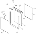
- FIG. 1 is an exploded perspective view of FIG. 1;
- FIG. 3 is a view showing an accommodation space formed in the filtering member to accommodate the first support member and the second support member in FIG.
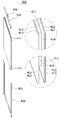
- FIG. 4 is a cross-sectional view along the A-A direction in FIG.
- FIG. 5 is a cross-sectional view along the B-B direction in FIG.
- FIG. 6 is a cross-sectional view taken along the C-C direction in FIG.
- FIG. 7 is a cross-sectional view taken along the line D-D in FIG. 1;
- FIG. 8 is a view of a portion of the second support member shown in FIG.
- FIGS. 9 to 12 are views showing a process of manufacturing a flat filter for water treatment according to a first embodiment of the present invention.
- FIG. 13 is a cross-sectional view along the A-A direction of Figure 1 in the flat filter for water treatment according to the second embodiment of the present invention
- FIG. 14 is a cross-sectional view taken along the B-B direction of FIG. 1 in the flat filter for water treatment according to the second embodiment of the present invention.
- 15 and 16 are views showing a process of manufacturing a flat filter for water treatment according to a second embodiment of the present invention.
- FIG. 17 is a view showing a flat filter for water treatment according to a third embodiment of the present invention.
- FIG. 18 is an exploded perspective view of FIG. 17;
- FIG. 19 is a view showing a receiving space formed in the filtering member for receiving the first support member and the second support member in FIG.
- 21 is a view showing a flat filter for water treatment according to a fourth embodiment of the present invention.
- FIG. 22 is an exploded view of FIG. 21,
- FIG. 23 is a view of a portion of the second support member shown in FIG. 21;
- FIG. 26 is a view illustrating an accommodation space formed in the filtration member to accommodate the first support member in FIG. 21;
- FIG. 27 is a view showing another example of the flat filter for water treatment according to the fourth embodiment of the present invention.
- FIG. 28 is an exploded view of FIG. 27;
- FIG. 29 is a view of a portion of the second support member in FIG. 27;
- FIG. 30 is a cross-sectional view taken along the line C-C in FIG. 27;
- 31 is a cross-sectional view taken along the line D-D in FIG. 27, and
- FIG. 32 is a view illustrating an accommodation space formed in the filtering member to accommodate the first supporting member and the second supporting member in FIG. 27.
- the flat filter 100 for water treatment includes a filtration member 110, an extension member 115, a first support member 120, and receiving as shown in FIGS.
- the structural body 130 includes a filtration member 110, an extension member 115, a first support member 120, and receiving as shown in FIGS.
- the structural body 130 includes a filtration member 110, an extension member 115, a first support member 120, and receiving as shown in FIGS.
- the structural body 130 includes a filtration member 110, an extension member 115, a first support member 120, and receiving as shown in FIGS.
- the filtration member 110 is to filter foreign substances contained in the filtration liquid, such as waste water, and a known filtration member may be used, but the nanofiber web 112 is disposed on both sides of the first support 111. It may be in the form of a plate.
- the nanofiber web 112 is to filter out foreign substances contained in the filtration liquid in the process of passing the filtration liquid by the suction pressure
- the first support 111 is the nanofiber
- the web 112 may be supported in a plate shape and serve as a moving passage through which the filtered water produced by the nanofiber web 112 moves.
- the filtration member 110 may have a three-layer structure in which the nanofiber web 112 is directly attached to both surfaces of the first support 111, the nanofiber web 112 and the first support ( It may be made of a five-layer structure in which a second second support 113 is interposed between the 111 (see Fig. 4).
- the filtering member 110 may be a single-layered filtering member or a conventional filtering member.
- the second support 113 may have a thickness relatively thinner than the thickness of the first support 111 to reduce the overall thickness of the filtration member 110, the second support 113 of the first support 111. It can be laminated on one side.
- the nanofiber web 112 is not attached directly to the first support 111, it is attached through the second support 113 can be improved adhesion and easily attached.
- the nanofiber web 112 may be attached to the first support 111 through the second support 113 through heat fusion, ultrasonic fusion, high frequency fusion.
- the second support 113 may be partially or entirely melted in the attachment process and attached to the first support 111.
- the nanofiber web 112 may have a melting temperature higher than the process temperature performed in the fusion process so that the nanofiber web 112 is not melted by heat
- the second support 113 is a process temperature performed in the fusion process It can have a lower melting temperature
- the filtration member 110 may be embodied in a three-layer structure in which the second support 113 is completely melted, and only a part of the second support 113 is melted to form the nanofiber web 112 and the first support. It may be implemented in a five-layer structure in which the second support 113 remains between the first support 111. However, the structure of the filtration member 110 is not limited thereto, and one or more support layers may be interposed between the two nanofiber webs 112.
- first support 111 and the second support 113 may be a porous substrate to serve as a moving passage through which the filtered water produced by the nanofiber web 112 moves.
- the first support 111 and / or the second support 113 may be any one of conventionally known fabrics, knitted fabrics, and nonwoven fabrics, and the nonwoven fabric may be a chemical bonding nonwoven fabric, a thermal bonding nonwoven fabric, or air. Dry nonwoven fabrics such as ray nonwoven fabrics, wet nonwoven fabrics, spunless nonwoven fabrics, known nonwoven fabrics such as needle punched nonwoven fabrics or meltblown can be used. Note that this may vary.
- first support 111 and / or the second support 113 is not limited in the material, for example, synthetic fibers or cellulose selected from the group consisting of polyester, polypropylene, nylon and polyethylene Natural fibers comprising a system may be used.
- the first support 111 and the second support 113 may be formed of a low melting polymer such as a low melting point polyester and a low melting polyethylene, which may be thermally fused.
- a low melting point polyester composite with a low melting point polyester fiber and a polyethylene terephthalate core with a low melting point composite fiber and / or a low melting point polypropylene based polypropylene low melting point composite fiber Can be.
- the melting point of the low melting polymer compound may be 60 ⁇ 180 °C
- the thickness of the first support 111 may be 2 ⁇ 200 ⁇ m, but is not limited thereto.
- the second support 113 applied to the present invention may be made of a different material from the first support 111, the first support 111 by being made of the same material as the first support 111. It can improve the adhesion with
- the nanofiber web 112 may be formed through the nanofiber to filter out foreign substances contained in the filtration solution.
- the nanofiber may include a fiber forming component including polyacrylonitrile (PAN) and polyvinylidene fluoride (PVDF) and an emulsifier to improve the miscibility of the fiber forming component.
- PAN polyacrylonitrile
- PVDF polyvinylidene fluoride
- the fiber forming component may include polyacrylonitrile having a high hydrophilicity (PAN, hereinafter referred to as PAN) and polyvinylidene fluoride having a very high hydrophobicity (PVDF, hereinafter referred to as PVDF).
- PAN polyacrylonitrile having a high hydrophilicity
- PVDF polyvinylidene fluoride having a very high hydrophobicity
- the PVDF can secure the mechanical strength and chemical resistance of the nanofibers due to the properties of the material, and the PAN has high hydrophilicity to prevent hydrophobization of the nanofibers due to the PVDF and to improve the hydrophilicity of the nanofibers. Improved water permeability can be expressed when is attached.
- the nanofiber web 112 may include a nanofiber web of a three-dimensional network structure.
- a fiber forming component comprising polyacrylonitrile (PAN) and polyvinylidene fluoride (PVDF) and a nanofiber comprising an emulsifier may be stacked perpendicular to the spinning surface, during air Due to the solvent which is not volatilized / evaporated, fusion may occur at a portion of the laminated nanofibers contacted between the fiber surfaces to form a three-dimensional network structure.
- the nanofiber web 112 as described above may be provided in a single layer or may be provided in a multi-layer.
- the nanofiber web 112 applied to the present invention may be provided to have a relatively wider area than the first support 111, and may be disposed on both sides of the first support 111.
- the nanofiber web 112 may include a first portion 112a disposed in an area corresponding to the first support 111 so as to cover one surface of the first support 111, and the first portion. And a second portion 112b extending outward from the edge of 112a (see FIG. 7).
- the area of the second portion 112b may be the remaining area obtained by subtracting the area of the first portion 112a from the total area of the nanofiber web 112.
- each nanofiber web 112 surrounds the edge of the first portion 112a.
- the two portions 112b may be disposed on one surface of the first support 111 so that a predetermined length protrudes outward from the edge of the first support 111, and the pair of second parts 112b facing each other
- the first support 111 may be spaced apart from each other by the thickness.
- the second portion 112b may be disposed entirely along the edge of the first support 111 (see FIG. 3).
- an accommodating space 114 defined by the width of the pair of second portions 112b facing each other and the thickness of the first support 111 may be formed, and the filtering space may be formed on the accommodating space 114 side.
- the first support member 120 for supporting the member 110 in the form of a flat plate may be inserted.
- the receiving member 114 may be provided with an extension member 115 for coupling with the receiving structure assembly 130.
- the second portion 112b protruding outward from the edge of the first support 111 may be directly fixed to one surface of the first support member 120 through heat fusion (see FIG. 7).
- the first support member 120 for supporting the filtration member 110 is inserted into the receiving space 114 side and then directly fixed to the filtration member 110 through heat fusion to bond the adhesive member. It does not need to be used or can be minimized.
- the nanofiber web 112 has a melting temperature that is similar to or lower than the process temperature performed in the fusion process so that at least a portion of the nanofiber web 112 may be melted by the heat applied during the heat fusion with the first support member 120.
- the first support member 120 may have a higher melting temperature than the process temperature performed in the fusion process so that the first support member 120 is not melted by heat applied during thermal fusion, and the polymer having excellent bonding strength with the nanofiber web 112 is heat. It may be made of a resin.
- the filtering member 110 is implemented with a structure of four or more layers in which at least one second support 113 is interposed between the first support 111 and the nanofiber web 112.
- the second support 113 may also be provided to have a relatively larger area than the first support 111 and may have the same area as the nanofiber web 112.
- the second support body. 113 may include an extension 113a extending from a plate-shaped body having a predetermined area and disposed in an area corresponding to the second portion 112b of the nanofiber web 112 (see FIG. 7). ).
- one surface of the extension part 113a may be laminated with the second part 112b. Accordingly, the extension portion 113a may also protrude outwardly from the edge of the first support 111 like the second portion 112b, and the width and the width of the pair of extension portions 113a facing each other.
- the accommodation space 114 defined by the thickness of the one support 111 may be formed.
- the area of the extension part 113a may be the remaining area obtained by subtracting the area of the first support 111 from the total area of the second support 113.
- the first support member 120 for supporting the filtration member 110 in the form of a flat plate may be inserted into the receiving space 114 side, the outer side from the edge of the first support 111
- the protruding extension 113a may be directly fixed to one end of the first support member 120 through heat fusion.
- the nanofiber web 112 and the second support 113 are firstly formed. It may have a melting temperature that is similar to or lower than a process temperature performed in the fusion process so that at least a portion thereof may be melted by heat during heat fusion with the support member 120, and the first support member 120 may have a second melting temperature.
- the support 113 may be made of a polymer resin having excellent bonding strength due to heat.
- the extension member 115 is for coupling the filtration member 110 and the receiving structure assembly 130.
- the extension member 115 is fixed to each of the pair of nanofiber web 112 at any one edge of the first support 111 is extended to the outside.
- the extension member 115 may be formed of a pair of plate-shaped members, and may be disposed above the first support 111.
- the pair of extension members 115 has a larger size than the second portion 112b of the pair of nanofiber webs 112 protruding outward from the first support 111. Accordingly, the pair of extension members 115 may protrude outward from the second portion 112b of the pair of nanofiber webs 112.
- the filtering member 110 is implemented with a structure of four or more layers in which at least one second support 113 is interposed between the first support 111 and the nanofiber web 112.
- the pair of extension members 115 may be fixed to a pair of second supports 113 protruding outward from the first support 111 to extend outwardly (see FIG. 4).
- the pair of extension members 115 may have a larger size in the extension portion 113a corresponding to the second portion 112b of the nanofiber web 112. Accordingly, the pair of extension members 115 may protrude outward from the extension portions 113a of the pair of second support members 113.
- the pair of extension members 115 are heat-sealed at the lower side of each of the second portion 112b of the pair of nanofiber webs 112 or the extension portions 113a of the pair of second supports 113. Can be fixed directly through (see FIG. 11).
- the pair of extension members 115 may be a thin film member.
- the extension member 115 may be a fluororesin-based film including at least one selected from polyethylene terephthalate (PET), polypropylene (PP), and poly tere terephthalate (PTFE).
- PET polyethylene terephthalate
- PP polypropylene
- PTFE poly tere terephthalate
- the pair of extension members 115 may have an upper side disposed between the pair of second support members 131 (see FIGS. 4 and 5).
- the pair of extension members 115 is a pair of nanofiber webs 112 on the outer surface that is fixed to the pair of nanofiber webs 112 or the pair of second support 113.
- the upper side protruding from the second portion 112b or the extension portion 113a of the pair of second support members 113 may be fixed to the pair of second support members 131 through heat fusion. .
- the second support member 131 for supporting the filtration member 110 is directly fixed to the filtration member 110 through heat fusion with the extension member 115, thereby eliminating or minimizing the need for using an adhesive member. Can be.
- the pair of extension members 115 may be made of the same material as the second support member 131, and in this case, the second support member 131 may be easily bonded and stably joined. have.
- the first support member 120 is disposed on the edge of the first support 111 to maintain the filtration member 110 in a plate shape.
- the first support member 120 is disposed to surround the remaining edge of the first support member 111 in which the extension member 115 is not disposed and is fixed to the filtration member 110.
- the first support member 120 may be formed of one member, or a plurality of first support members 120 may be connected to each other.
- the first support member 120 may have a substantially "C" shape.
- the first support member 120 may be a thin film member.
- the first support member 120 may be a fluororesin-based film including at least one selected from polyethylene terephthalate (PET), polypropylene (PP), and poly tere terephthalate (PTFE).
- PET polyethylene terephthalate
- PP polypropylene
- PTFE poly tere terephthalate
- the material of the first support member 120 is not limited thereto, and it may be understood that the first support member 120 may be formed of a thin metal material.
- first support member 120 is formed between a pair of second portions 112b or a pair of extension portions 113a which protrude from the ends of the first support 111 to face each other.
- a portion of the receiving space 114 may be disposed to be inserted, and end portions of the second portion 112b or the extension portion 113a may be fixed to both surfaces of the first support member 120, respectively.
- the second portion 112b or the extension portion 113a protruding outward from the edge of the first support 111 may be directly fixed through heat fusion to one surface of the first support member 120. Can be.
- the first support member 120 is directly fixed to the filtration member 110 through heat fusion without using an adhesive member. Use is minimized or unnecessary.
- the first support member 120 is filtered so that the end side disposed between the second portion 112b or the extension portion 113a facing each other is spaced apart from the end of the first support 111. It may be fixed to the member 110.
- the first flow passage 122 through which the fluid flows is formed at the edge of the first support 111 so that the filtered water produced through the filtering member 110 may flow into the first flow passage 122. (See FIG. 7).
- first flow path 122 of the first support member 120 is formed to communicate with each other along the edge of the first support 111, the second disposed adjacent to the first support member 120
- the second channel 133 of the support member 131 may be disposed to communicate with each other.
- the first support member 120 disposed at the left and right edges of the filtration member 110 may include a second support having the first flow passage 122 disposed at the upper edge of the filtration member 110.
- the second flow path 133 of the member 131 may be disposed so as to communicate with the first flow path 122 of the first support member 120 disposed on the lower edge side of the filtering member 110, respectively.
- the filtered water produced through the filtration member 110 moves directly to the second flow passage 133 or moves to the second flow passage 133 via the first flow passage 122 to receive the water inlet 136. Can be discharged to the outside.
- Receiving structure 130 is connected to the receiving port 136 and the filtration member 110 at the same time the one side of the first support 111, for example, the upper edge is disposed on the filter member 110 in the form of a plate Is to maintain.
- the receiving structure assembly 130 includes a second support member 131 and at least one receiving port 136.
- the second support member 131 supports the filtration member 110 together with the first support member 120 in the form of a plate, and is produced from the filtration solution by the nanofiber web 112. It may serve as a flow path for moving the filtered water to the receiving port 136 side through the suction force provided from the outside.
- the second support member 131 is composed of a pair of plate-like members.
- the pair of second support members 131 may be fixed to each other along the outer portion except for a portion of the lower side fixed to the pair of extension members 115.
- the pair of second supporting members 131 may include fixing parts 131a fixed to each other along the outer portion and separation parts 131b which are not fixed to each other (see FIG. 10).
- a second flow path through which the filtered water flowing from the filtering member 110 moves between the separating portions 131b of the pair of second supporting members 131 and between the pair of extension members 115 ( 133 may be formed, and one side of the second support member 131 may be provided with a receiving port 136 communicating with the second flow path 133 (see FIG. 4).
- a second flow path 133 through which the fluid can flow between the pair of second support members 131 may be formed along the longitudinal direction. That is, a second flow path 133 may be formed between the separating portions 131b of the pair of second supporting members 131 (see FIG. 5).
- the second flow path 133 is formed between the pair of nanofiber webs 112 or the pair of second support members 113. It may be formed to communicate with the first passage 122 (see FIG. 6).
- the discharge path may be discharged to the outside through the at least one receiving port 136 (FIG. 8).
- a fluid such as washing water provided from the outside flows directly through the at least one receiving port 136 and then moves directly to the second channel 133 or through the second channel 133. After moving to the side 122, it may be supplied to the filtration member 110.
- the pair of second supporting members 131 may be a thin film member.
- the pair of second support members 131 may be a fluororesin-based film including at least one selected from polyethylene terephthalate (PET), polypropylene (PP), and polytere terephthalate (PTFE).
- PET polyethylene terephthalate
- PP polypropylene
- PTFE polytere terephthalate
- the second support member 131 may be laminated with each other through heat fusion along the outer portion except for a part of the lower side connected to the pair of extension members 115.
- the pair of second supporting members 131 are disposed such that an upper side thereof surrounds a lower side of the at least one receiving port 136. That is, the pair of second supporting members 131 may be fixed along the outer periphery at the lower side of the at least one receiving port 136 (see FIG. 4).
- the pair of second support members 131 may be fixed to the outer periphery of the lower portion of the receiving port 136 through heat fusion in a state disposed on both sides of the receiving port 136 on the lower side, respectively. (See FIG. 9).
- the pair of second supporting members 131 may be laminated equally by an interval at which an upper side thereof is fixed to an outer periphery of the receiving port 136, but is not limited thereto. It can be laminated differently from the outer periphery of.
- the pair of second supporting members 131 may be disposed at one side of the edge of the filtering member 110, and the lower side of the pair of second supporting members 131 may be disposed outside the pair of extension members 115. 115, respectively, is fixed to the upper side.
- the pair of second support members 131 may be fixed through heat fusion in a state where the lower side of the separating part 131b is disposed outside the upper portion of the pair of extension members 115 (FIG. 12).
- the second support member 131 is directly fixed to the extension member 115 through heat fusion without using an adhesive member, thereby providing an adhesive member. Use is minimized or unnecessary.
- the flat filter 100 for water treatment includes a receiving structure assembly 130 disposed at one edge of the filtration member 110 and a first edge disposed at the other edge.
- the support member 120 can maintain the shape of the flat plate of the filter member 110 and at the same time the first support member 120 and the second support member 131 is formed of a thin film member to reduce the overall weight Thinning can be achieved.
- the receiving port 136 is for discharging the filtered water from which foreign matter is removed by the filtering member 110 to the outside or supplying a fluid such as washing water for cleaning the filtering member 110 to the filtering member 110. will be.
- the receiving port 136 is formed such that the inner diameter of the outer side 136a is larger than the inner diameter of the inner side 136b. That is, the receiving port 136 has a receiving hole penetrating the inside thereof, the outer side 136a connected to the external pump has an inner diameter than the inner side 136b fixed to the second support member 131. It can be formed large.
- the inner side 136b having a small inner diameter at the time of discharging the filtered water through the inlet 136 has a high flow rate, but a low pressure
- the outer side 136a having a large inner diameter has a low flow rate, but a high pressure.
- the filtered water can be easily discharged from the inner side 136b of the inlet 136 to the outer side 136a. Therefore, the amount of filtrate discharged from the receiving port 136 can be increased even by the same external pressure, so that the filtration efficiency can be improved.
- the fluid such as wash water when supplying a fluid such as wash water through the inlet 136, the fluid such as wash water is higher due to the pressure provided by the pump that the outer side 136a is higher than the inner side 136b and further connected to the outer side 136a. Can be easily supplied from the outer side 136a of the receiving port 136 to the inner side 136b. Therefore, the same external pressure can also increase the amount of fluid, such as the wash water supplied through the inlet 136, thereby improving the washing efficiency.
- the flat filter 100 for water treatment may include a first support member 120 and a second support member that form a first flow path 122 and a second flow path 133.
- 131 is made of a plate-like film member to configure different inner diameters of the outer side and the inner side of the receiving port 136 even when the cross-sectional area of the flow path is relatively small, thereby compensating for the decrease in filtration efficiency and washing efficiency due to thinning. Can be.
- At least one fastening hole 121 or 132 may be formed in the first support member 120 and the second support member 131.
- the fastening hole 121 is formed in the corner portion of the first support member 120
- the fastening hole 132 is formed in the fixing portion (131a) at both ends of the second support member 131. Can be.
- Such fastening holes 121 and 132 are formed when the filter module is formed using the flat filter 100 for water treatment according to the first embodiment of the present invention so that a plurality of flat filter for water treatment is passed through a fastening bar (not shown). It is for integrating (100).
- the flat filter for water treatment according to the second embodiment of the present invention may be the same as or similar to the flat filter 100 for water treatment according to the first embodiment of the present invention as described above except for the receiving assembly 230. Can be.
- the flat filter for water treatment includes a filtration member 210, an extension member 215, a first support member 220, and a receiving structure assembly 230.
- the filtration member 210, the first support member 220, and the extension member 215 are respectively the filtration member 110 of FIG. 1, the first support member 120, and the extension member 115 of FIG. 4. It may be the same or similar.
- the pair of extension members 215 may be disposed between the folded side surfaces of the second support member 231 (see FIGS. 13 and 14).
- the pair of extension members 215 is a pair of nanofiber web 212 on the outer surface fixed to the pair of nanofiber web 212 or the pair of second support 213.
- the upper side protruding from the second portion 212b or the extension portion 213a of the pair of second support members 213 may be fixed to the folded side surfaces of the second support member 231 through heat fusion. .
- the second support member 231 for supporting the filtration member 210 is directly fixed to the filtration member 210 through thermal fusion with the extension member 215, thereby eliminating or minimizing the need for using an adhesive member. Can be.
- the pair of extension members 215 may be made of the same material as the second support member 231, and in this case, the second support member 231 may be easily bonded as well as stably joined. have.
- Receiving structure 230 is connected to the receiving port 236 and the filtration member 210 at the same time arranged on one side of the first support 211, for example, the upper rim of the filter member 210 in the form of a plate This is to maintain (see Fig. 15).
- the receiving structure assembly 230 includes a second support member 231 and at least one receiving port 236.
- the second support member 231 is composed of one plate member. In this case, both ends of the second support member 231 may be fixed to each other in a state where one plate member is folded.
- the lower ends of the second support member 231 may be fixed to each other, except for a portion fixed to the pair of extension members 215.
- the second support member 231 may include a fixing part 231a fixed to each other at both ends and a separating part 231b which is not fixed to each other, similarly to FIG. 10.
- the flat filter for water treatment according to the second embodiment of the present invention does not use a pair of plate-shaped members, and folds one plate-shaped member to form only the second flow path 233. Since the sealing is necessary, the second channel 233 can be stably formed while minimizing the sealing structure, thereby improving the reliability of the product.
- a receiving port 236 communicating with the second flow path 233 may be provided at one side of the second support member 231.
- a second flow path 233 through which a fluid can flow between both side surfaces of the second support member 231 in a folded state may be formed along the length direction. That is, a second flow path 233 may be formed between the separating portions 231b of the second support member 231 (see FIG. 14).
- the second flow path 233 is disposed between the pair of nanofiber webs 212 or the pair of second supports 213. It may be formed to communicate with the first flow path 222 is formed.
- the filtered water in which foreign matters are filtered while moving to the inside of the filtration member 210 by a suction force provided from a pump (not shown) is formed in each of the first flow paths formed in the first support member 220. After moving to the second flow path 233 formed in the second support member 231 or directly to the second flow path 233 via the 222 through the at least one receiver 236 to the outside May be discharged.
- a fluid such as washing water provided from the outside flows directly through the at least one inlet 236 and then moves directly to the second channel 233 or through the second channel 233. After moving to the (222) side may be supplied to the filtering member (210).
- the second support member 231 may be a thin film member.
- the second support member 231 may be a fluororesin-based film including at least one selected from polyethylene terephthalate (PET), polypropylene (PP), and poly tere terephthalate (PTFE).
- PET polyethylene terephthalate
- PP polypropylene
- PTFE poly tere terephthalate
- the second support member 231 has at least one through hole 234 into which the receiving hole 236 is inserted.
- the at least one through hole 234 may be formed at a folded portion of the second support member 231, that is, at an upper side of the second support member 231 in a folded state (see FIG. 15). .
- the second support member 231 may be fixed through heat fusion along the outer periphery on the insertion side of the at least one receiving port 236, similar to FIG.
- the second support member 231 may be fixed only to the edge of the through hole 234 and the receiver 236, but is not limited thereto, and may be fixed to surround the outer circumference of the receiver. .
- both sides of the upper end of the second support member 231 are in close contact with each other so as to surround the outer periphery of the receiver 236. It can be fixed through heat fusion.
- the second support member 231 has a lower side of each side of the folded side of the filtration member 210, the lower side of the pair of extension members 215 is disposed outside the pair of extension members 215 Are respectively fixed to the upper side of the
- the second support member 231 may be fixed through heat fusion in a state in which the lower side of the separation unit 231b is disposed outside the upper portion of the pair of extension members 215 (see FIG. 16). ).
- the second support member 231 is directly fixed to the extension member 215 through heat fusion without using the adhesive member, thereby minimizing the use of the adhesive member. Or unnecessary.
- the flat filter for water treatment includes a receiving structure 230 disposed at one edge of the filtration member 210, and a first support member disposed at the other edge.
- the first support member 220 and the second support member 231 are formed of a thin film member to reduce the overall weight and reduce the thickness, while allowing the 220 to maintain the shape of the flat plate of the filtration member 210. Can be implemented.
- the receiving port 236 is for discharging the filtered water from which the foreign matter has been removed by the filtering member 210 to the outside or supplying a fluid such as washing water for cleaning the filtering member 210 to the filtering member 210. will be.
- This receiving port 236 is formed larger than the inner diameter of the inner side of the outer side. That is, the receiving port 236 has a receiving hole penetrating the inside thereof, the outer side connected to the external pump is an inner diameter than the inner side inserted into the through hole 234 of the second support member 231. It can be formed large.
- the flat filter 300 for water treatment according to the third embodiment of the present invention is the flat filter for water treatment according to the first and second embodiments of the present invention as described above, except for the filtration member 310. Same as or similar to 100).
- the same technical features as the flat filter 100 for water treatment according to the first and second embodiments of the present invention are omitted, and the flat filter 300 for water treatment according to the third embodiment of the present invention is omitted.
- Technical features not specifically described with respect to the same can be understood from the corresponding components of the flat filter 100 for water treatment according to the first and second embodiments.
- the flat filter 300 for water treatment includes a filtration member 310, a first support member 320, and a receiving structure assembly 330 as shown in FIGS. 17 to 19. Include.
- the filtering member 310 may be the same or similar to the material of the filtering member 110 of FIG.
- the receiving assembly 330 may be the same as or similar to the receiving assembly 130 of FIG. 9 or the receiving assembly 230 of FIG. 13.
- the filtration member 310 is for filtering foreign substances contained in the filtration liquid such as waste water, and a known filtration member may be used, but the nanofiber web 312 is integrally formed on both sides of the first support 311. It may be in the form of a plate placed.
- the filtration member 310 may be implemented in a three-layer structure in which the second support 313 is completely melted, and only a part of the second support 313 is melted to form the nanofiber web 312 and the first. It may be implemented in a five-layer structure in which the second support 313 is left between the support 311.
- the structure of the filtration member 310 is not limited thereto, and one or more support layers may be interposed between the first support 311 and the nanofiber web 312, and may be an existing filtration member. Reveal.
- the nanofiber web 312 applied to the present invention may be formed on one side of the first support 311 in a folded state made of one plate-like member.
- the nanofiber web 312 may be disposed in a folded state to surround both sides of the first support 311.
- the nanofiber web 312 may be formed with a first flow path 323 through which fluid flows between both sides of the folded portion (see FIG. 20).
- the flat filter 300 for water treatment according to the third embodiment of the present invention may omit a support member for supporting the edge of the filtration member 310 in the folded portion of the nanofiber web 312. This can increase work productivity.
- the first passage 323 may be formed by the surface extended to the surface, thereby eliminating the need for a separate sealing operation, thereby increasing production productivity.
- the flow path can be stably formed while minimizing the overall sealing structure of the filtration member 310, the reliability of the product can be improved.
- nanofiber web 312 since only part of the nanofiber web 312 is required to be sealed, a sealing process such as heat fusion can be minimized, thereby reducing manufacturing costs.
- the nanofiber web 312 may be formed to extend outward from the edge of the first support 311. That is, the nanofiber web 312 may have a larger area than the first support 311 has an area of one side folded.
- the nanofiber web 312 is a first portion disposed in a region corresponding to the first support 311 so as to cover one surface of the first support 311 on one side folded like FIG. 312a and a second portion 312b extending outward from an edge of the first portion 312a.
- the area of the second portion 312b may be the remaining area of the total area of the folded one side of the nanofiber web 312 minus the area of the first portion 312a.
- each nanofiber web 312 surrounds the edge of the first portion (312a)
- the two parts 312b may be disposed on one surface of the first support 311 so as to protrude a predetermined length outward from the edge of the first support 311, and the pair of second parts 312b facing each other may be
- the first support 311 may be spaced apart from each other by the thickness.
- the second portion 312b may be disposed along the edge of the first support 311 except for the folded portion (see FIG. 19).
- an accommodation space 314 defined by the width of the pair of second portions 312b facing each other and the thickness of the first support 311 may be formed, and the filtering space may be formed at the accommodation space 314 side.
- the first support member 320 may be inserted to support the member 310 in the form of a flat plate.
- an extension member 315 for engaging with the receiving structure assembly 330 may be disposed at the receiving space 314 side opposite to the folded portion.
- the filtration member 310 is implemented with a structure of four or more layers in which at least one second support 313 is interposed between the first support 311 and the nanofiber web 312
- the second support 313 may also be provided to have a relatively larger area than the first support 311 and may have the same area as the nanofiber web 312.
- the filtration member 310 when the filtration member 310 is implemented in a five-layer structure in which the second support 313 and the nanofiber web 312 are sequentially stacked on both surfaces of the first support 311, the second support body.
- the 313 may be disposed on both sides of the first support 311 in a folded state with the nanofiber web 312.
- the second support 313 extends from the plate-shaped body having a predetermined area similar to FIG. 7 and is disposed in an area corresponding to the second portion 312b of the nanofiber web 312 ( 313a).
- one surface of the extension part 313a may be laminated with the second part 312b. Accordingly, the extension part 313a may also protrude outward from the edge of the first support 311 like the second part 312b, and the width and the width of the pair of extension parts 313a facing each other may be different from each other.
- the accommodation space 314 defined by the thickness of the one support 311 may be formed.
- the area of the extension part 313a may be the remaining area obtained by subtracting the area of the first support 311 from the entire area of the folded one side surface of the second support 313.
- the first support member 320 for supporting the filtration member 310 in the form of a flat plate may be inserted into the receiving space 314 side, the outer side from the edge of the first support 311
- the protruding extension portion 313a may be directly fixed to the end side of the first support member 320 by heat fusion.
- the nanofiber web 312 and the second support 313 may include a first support. It may have a melting temperature that is similar to or lower than a process temperature performed in the fusion process so that at least a portion thereof may be melted by heat during thermal fusion with the support member 320, and the first support member 320 may have the second
- the support 313 may be made of a polymer resin having excellent bonding strength due to heat.
- the flat filter 300 for water treatment may include an extension member 315.
- the extension member 315 is for coupling the filtration member 310 and the receiving structure assembly 330.
- the extension member 315 is fixed to both folded side surfaces of the nanofiber web 312 at the edge of the first support member 311 adjacent to the first support member 320 and extends to the outside.
- the extension member 315 may be formed of a pair of plate-shaped members, and may be disposed above the first support 311.
- the pair of extension members 315 has a larger size than the second portion 312b of the nanofiber web 312 protruding outward from the first support 311. Accordingly, the pair of extension members 315 may protrude outward from the second portion 312b of the nanofiber web 312.
- the pair of extension members 315 may have a larger size than the extension portion 313a corresponding to the second portion 312b of the nanofiber web 312. Accordingly, the pair of extension members 315 are externally from the second portions 312b of the folded side surfaces of the nanofiber web 312 or the extensions 313a of the pair of second supports 313. It may protrude.
- the pair of extension members 315 extend from the second side 312b or the pair of second supports 313 on both sides of the folded nanofiber web 312.
- Each of the portions 313a may be directly fixed through heat fusion.
- the pair of extension members 315 may be disposed between two folded side surfaces of the second support member 331 similarly to FIGS. 13 and 15.
- the pair of extension members 315 may be folded at both sides of the nanofiber web 312 or at an outer surface fixed with the pair of second supports 313, and at both sides of the nanofiber web 312.
- the upper side protruding from the second portion 312b or the extension portion 313a of the pair of second support members 313 may be fixed to both folded sides of the second support member 331 through heat fusion. .
- the second support member 331 for supporting the filtration member 310 is directly fixed to the filtration member 310 through thermal fusion with the extension member 315, thereby eliminating or minimizing the need for using an adhesive member. Can be.
- the pair of extension members 315 may be made of the same material as the second support member 331, and in this case, the second support member 331 may be easily bonded as well as stably joined. have.
- the first support member 320 is disposed on the edge of the first support 311 to hold the filtration member 310 in a plate shape.
- the first support member 320 is disposed to surround both edges adjacent to the extension member 315 among the edges of the first support 311 and is fixed to the filtration member 310.
- the first support member 320 may be formed in a pair of the same shape.
- the second flow path 322 by the first support member 320 is formed to communicate with each other along the edge of the first support 311, the first disposed adjacent to the first support member 320
- One euro 323 may be arranged to communicate with each other.
- the first support member 320 disposed at the left and right edges of the filtration member 310 may have a second support having the second flow passage 322 disposed at the upper edge of the filtration member 310.
- the third channel 333 of the member 331 and the first channel 323 of the folded portion of the nanofiber web 312 disposed on the lower edge side of the filtering member 310 are arranged to communicate with each other. Can be.
- the filtered water produced through the filtration member 310 moves directly to the third flow path 333 or through the first flow path 323 and / or the second flow path 322. 333 may be discharged to the outside through the receiving port 336.
- Receiving structure 330 is connected to the receiving port 336 and the filtration member 310 at the same time arranged on one side of the first support 311, for example, the upper edge of the filter member 310 in the form of a plate Is to maintain.
- the receiving structure assembly 330 includes a second support member 331 and at least one receiving port 336.
- the second support member 331 supports the filtration member 310 together with the first support member 320 in the form of a plate, and is produced from the filtration solution by the nanofiber web 312. It may serve as a flow path for moving the filtered water to the receiving port 336 through the suction force provided from the outside.
- the second support member 331 is made of a single plate-like member similar to FIG.
- the second support member 331 may be a part of the both ends of the folded in a state where one plate-like member is folded.
- the lower ends of the second support member 331 may be fixed to each other, except for a portion fixed to the pair of extension members 315.
- the second support member 331 may include a fixing part 331a fixed to each other at both ends and a separating part 331b which is not fixed to each other.
- the flat filter 300 for water treatment according to the third embodiment of the present invention does not use a pair of plate-shaped members, and folds and uses one plate-shaped member so that only three ends thereof have a third flow path 333. Since the sealing is necessary to form the third channel 333 can be stably formed while minimizing the sealing structure, thus, it is possible to improve the reliability of the product.
- the sealing is required only at both ends of the second support member 331, the sealing process such as heat fusion may be minimized, thereby reducing manufacturing costs and further improving work productivity.
- a third flow path 333 through which the fluid can flow may be formed along the length direction between both sides of the second support member 331 in the folded state. That is, a third flow path 333 may be formed between the separating parts 331b of the second supporting member 331.
- the third flow path 333 is formed between the two ends of the nanofiber web 312 or between the pair of second support members 313 ( 322 may be configured to communicate.
- the filtered water filtered while moving to the inside of the filtration member 310 by a suction force provided from a pump (not shown) passes through the first flow path 323 formed in the folded portion of the nanofiber web 312. Or move to the third flow path 333 formed on the second support member 331 via each second flow path 322 formed on the first support member 320 or directly to the third flow path 333. Then it may be discharged to the outside through the at least one receiver 336 (see Figure 4).
- a fluid such as washing water provided from the outside flows through the at least one inlet 336 and then moves directly to the third channel 333 or through the third channel 333. After moving to the 323 or the second flow path 322 may be supplied to the filtering member (310).
- the second support member 331 has at least one through hole into which the receiving hole 336 is inserted.
- the at least one through hole may be formed at a folded portion of the second support member 331, that is, at an upper side of the second support member 331 in a folded state, similarly to FIG. 4.
- the second support member 331 may be fixed through heat fusion along the outer periphery to the insertion side of the at least one receiving port 336.
- the second support member 331 may be fixed only to the edge of the through hole with the receiver 336, but is not limited thereto, and may be fixed to surround the outer circumference of the receiver.
- the second support member 331 is heat-sealed in a state in which both sides of the upper end of the receiving opening 336 is inserted into the through-hole, so as to surround the outer periphery of the receiving opening 336 Can be fixed through.
- the second support member 331 is one side of the rim of the filtering member 310, the lower side of the folded both sides is disposed on the outside of the pair of extension member 315 the pair of extension members 315 Are respectively fixed to the upper side of the
- the second support member 331 may be fixed through heat fusion in a state where the lower side of the separating part 331b is disposed outside the upper portion of the pair of extension members 315.
- the second support member 331 is directly fixed to the extension member 315 through heat fusion without using an adhesive member, thereby providing an adhesive member. Use is minimized or unnecessary.
- the flat filter 300 for water treatment includes a receiving structure assembly 330 and a receiving structure assembly 330 disposed on one edge of the filtration member 310.
- the first support member 320 and the second support member 331 are thin film members while maintaining the shape of the flat plate of the filtration member 310 to the first support member 320 disposed in the adjacent edge. By forming it can reduce the overall weight and implement a thinner.
- At least one fastening hole 321 and 332 may be formed in the first support member 320 and the second support member 331.
- the fastening hole 321 is formed on one side of the lower portion of the first support member 320
- the fastening hole 332 is formed in the fixing portion 331a at both ends of the second support member 331.
- the fastening hole 321 may be formed near a corner of the filtering member 310.
- the fastening hole 321 may be the same or similar in function and shape of the fastening hole 121 of FIG.
- the second support member 331 may be formed of a pair of plate members similarly to FIGS. 3 and 4.
- the flat filter 400 for water treatment according to the fourth embodiment of the present invention except for the support frame 420 and the connecting member 430 is another component of the flat water treatment as shown in Figs. It may be the same as or similar to the filter 100.
- planar filters 100 and 300 for water treatment according to the first to third embodiments of the present invention are omitted, and the flat filter 400 for water treatment according to the fourth embodiment of the present invention is omitted.
- Technical features that are not specifically described above may be equally understood from corresponding components of the planar filters 100 and 300 for water treatment according to the first to third embodiments.
- the planar filter 400, 500 for water treatment according to the fourth embodiment of the present invention includes a filtration member 410 and a plurality of support members 420, 430, 530 as shown in FIGS. 21, 22, 27, and 28.
- the filtration member 410 may be the same as or similar to the filtration member 110 of FIG.
- the filtration member 410 may have a three-layer structure in which the nanofiber web 412 is directly attached to both surfaces of the first support 411, and the nanofiber web 412 and the first support 411 may be formed. It may be made of a five-layer structure in which a separate second support 413 is interposed therebetween (see FIGS. 24 and 30).
- the filtration member 410 may include a first portion 412a disposed in an area corresponding to the first support 411 such that the nanofiber web 412 covers one surface of the first support 411, and A second portion 412b may extend outwardly from an edge of the first portion 412a (see FIGS. 25 and 31).
- the second portion 412b may be disposed entirely along the edge of the first support 411 (see FIG. 32), or only on the remaining edge side except for some edges of the edge of the first support 411. It may be arranged (see FIG. 26).
- the support members 420, 430, and 530 are disposed on the edge of the first support 411 to maintain the filtration member 410 in a plate shape.
- the support members 420, 430, and 530 may have the same or similar materials and functions as those of the first support member 120 of FIG. 1.
- the support member may be formed as a single member to support or partially support the edge of the filtering member 410 as a whole, but the plurality of support members 420, 430, and 530 are respectively provided at the edge of the first support 411. It may be in a form arranged.
- the plurality of support members 420, 430, 530 may include a first support member 420 made of a plate-like member and a second support member 430, 530 made of a frame, and the second support members 430, 530 may be provided. It may be disposed on the upper edge side of the filtering member 410 and the first support member 420 is disposed on the remaining edge side.
- first support member 420 may be formed of one member, or a plurality of first support members 420 may be connected to each other.
- the flat filter for water treatment 400, 500 includes a frame in which the support members 430 and 530 of the plurality of support members disposed on the edge of the filtration member 410 have rigidity. It is made of a structure to prevent the bending or deformation due to external force to maintain the shape of the filtration member 410 flat plate and at the same time the remaining support member 420 is formed of a thin film member to reduce the overall weight and implement a thinner Can be.
- first passage 422 of the first support member 420 is arranged to communicate with the second passage 433 of the second support members 430 and 530 disposed adjacent to the first support member 420.
- Each of the first flow passages 422 formed on the plurality of first support members 420 may communicate with the first flow passages 422 formed on the first support members 420 disposed adjacent to each other.
- the first support member 420 disposed at the left and right edges of the filtration member 410 may have a second support having the first passage 422 disposed at the upper edge of the filtration member 410.
- the first passage 422 of the first supporting member 420 may be disposed to communicate with each other.
- the filtered water produced through the filtration member 410 moves directly to the second flow path 433 or moves to the second flow path 433 via the first flow path 432. Can be discharged to the outside.
- At least one fastening hole 421 may be formed in the first support member 420.
- Such a fastening hole 421 is a plurality of water treatment plate type filter by passing through the fastening bar (not shown) when configuring the filter module using the water treatment flat filter (400,500) according to the fourth embodiment of the present invention It is for integrating (400,500).
- the second supporting members 430 and 530 may be provided in an approximately 'C' shape having one side open, and a second flow passage 433 through which the filtered water introduced from the filtering member 410 moves may be formed.
- a receiving port 436 communicating with the second passage 433 may be provided at one side of the second supporting members 430 and 530 (see FIGS. 24 and 30).
- the second support members 430 and 530 may be formed of a plate-shaped first plate 431 and a pair of plates extending from the first plate 431 in a direction perpendicular to the first plate 431, respectively.
- the second channel 433 may include a second plate 432a and 432b, and the second channel 433 may extend along the length direction of the second support member 430 and 530 between the pair of second plate 432a and 432b facing each other. Can be formed.
- at least one receiving hole 431a is formed in the middle of the length of the first plate 431 so as to communicate with the second passage 433, and the receiving opening is located at a position corresponding to the receiving hole 431a. 436 may be combined.
- the second support members 430 and 530 may be fixed to the filtration member 410 in such a manner that an edge side of the filtration member 410 is inserted between the pair of nanofiber webs 412 facing each other. It may be fixed to the filtration member 410 in the inserted form.
- the second support member 430 may include a restraining member 435 for limiting the insertion depth of the filtration member 410 on opposite surfaces of the pair of second plates 432a and 432b facing each other. Can be formed (see FIG. 24).
- the insertion depth of the filtering member 410 is limited through the restraining member 435 while the edge side of the filtering member 410 is coupled to the second support member 430, thereby filtering the filter member 410.
- a predetermined space may be formed between the upper edge side of the and the inner surface of the first plate 431.
- the upper edge of the filtration member 410 is always kept spaced from the first plate 431, such as filtered or washed water.
- a second flow path 433 through which the fluid can move may be formed.
- fluids introduced into the second flow path 433 are provided at both end sides of the second support member 430 by separate sealing members 437 for sealing both open ends of the second flow path 433. Can be prevented from leaking to the outside through the end side of the second support member 430 (see FIGS. 22 and 23).
- the sealing member 437 may be made of the same material as the second support member 430, may be made of a rubber material, or may be in the form of a hardened adhesive.
- the sealing member 437 may be formed integrally with the second supporting member 430.
- the restraining member 435 may be formed on opposite surfaces of the pair of second plates 432a and 432b facing each other, but among the pair of second plates 432a and 432b. It may be formed only on either inner surface.
- the restraining member 435 may be provided in the longitudinal direction of the second support member 430 or may be partially provided.
- the restraining members 435 are spaced apart to have a predetermined interval so that the filtration is performed. Filtrate water produced through the member 410 may be moved to the second flow path 433 through the gap.
- the second support member 230 may have an outer surface of the second plates 432a and 432b extending from the second portion 412b or the second support 413 of the nanofiber web 412. 413a may be integrated with the filtration member 410 by being fixed through heat fusion (see FIG. 30).
- the second support member 230 is a pair of plate-like first plate 431 and a pair of extending from the first plate 431 in a direction perpendicular to the first plate 431, respectively.
- the second channel 433 may include second plates 432a and 432b, and the second channel 433 may extend along the length direction of the second support member 230 between the pair of second plates 432a and 432b facing each other. Can be formed.
- the filtration member 410 is between the pair of second portions 412b facing each other by the second portion 412b of the nanofiber web 412 protrudes outward from the end of the first support 411.
- the predetermined receiving space 414 may be formed in the.
- the extension portion 413a of the second support 413 is also outside from the end of the first support 411.
- the predetermined receiving space 414 may be formed between the pair of extension portions 413a facing each other by protruding to each other.
- the outer surface of the second plates 432a and 432b and the second part 412b of the nanofiber web 412 or At least a portion of the second portion 412b or the extension portion 413a is fixed to each other through heat fusion through thermal fusion in a state where the extension portions 413a of the second support 413 are interviewed with each other. It can be integrated with the filtration member 410.
- At this time, at least one protruding portion 434 protruding a predetermined length outwardly may be formed on the free end portions of the pair of second plates 432a and 432b (see FIG. 30).
- the protrusion 434 may protrude along the longitudinal direction of the second plates 432a and 432b at the end sides of the second plates 432a and 432b, and the second support member 230 may be formed.
- the protrusion 434 When inserted into the accommodation space 414, the protrusion 434 may be driven by an external force on the edge end side of the first support 411.
- the above-described flat filter for water treatment (100, 300, 400) can be applied to a known wastewater treatment system.
Landscapes
- Chemical & Material Sciences (AREA)
- Chemical Kinetics & Catalysis (AREA)
- Life Sciences & Earth Sciences (AREA)
- Hydrology & Water Resources (AREA)
- Engineering & Computer Science (AREA)
- Environmental & Geological Engineering (AREA)
- Water Supply & Treatment (AREA)
- Organic Chemistry (AREA)
- Separation Using Semi-Permeable Membranes (AREA)
- Filtering Materials (AREA)
Abstract
수처리용 평판형 필터가 제공된다. 본 발명의 일 실시예에 따른 수처리용 평판형 필터는 소정의 면적을 갖는 판상의 제1지지체와, 제1지지체보다 넓은 면적을 갖고 제1지지체의 양면에 나노섬유로 형성되는 한 쌍의 나노섬유웹을 포함하는 여과부재; 제1지지체의 어느 하나의 테두리에서 한 쌍의 나노섬유웹 각각에 고정되어 외부로 연장되는 한 쌍의 연장부재; 제1지지체의 나머지 테두리를 감싸도록 배치되며 여과부재에 고정되는 제1지지부재; 및 여과수를 외부로 배출하기 위한 적어도 하나의 수취구와, 적어도 하나의 수취구의 일측을 감싸도록 배치되며 한 쌍의 연장부재 각각에 고정되는 한 쌍의 제2지지부재를 포함하는 수취구조립체;를 포함한다. 여기서, 제1지지부재, 한 쌍의 연장부재 및 한 쌍의 제2지지부재는 판상의 부재로 이루어지고, 적어도 하나의 수취구는 외부측의 내경이 여과부재측의 내경보다 크다.
Description
본 발명은 수처리용 평판형 필터에 관한 것이다.
일반적으로 산업이 급속한 발전과 인구의 도시 집중 등으로 인하여 도시 하수 및 산업폐수가 증가하였다. 이러한 오폐수의 증가는 현대 사회에 커다란 문제가 되고 있으며, 이를 경제적이고 효율적으로 처리하기 위한 다양한 오폐수 처리시설이 제시되고 있다.
이러한 오폐수 처리시설에는 오폐수를 여과하기 위하여 복수 개의 필터가 구비될 수 있으며, 각각의 필터에 포함되는 여과부재를 통하여 오폐수가 여과된다.
이때, 여과부재가 소정의 면적을 갖는 평판형으로 구비되는 경우 상기 여과부재의 테두리측에는 상기 여과부재를 지지하기 위한 지지부재(또는 프레임)가 체결된다.
통상적으로 필름부재에 의해 여과부재를 지지하는 경우, 상기 프레임은 접착부재를 매개로 여과부재의 테두리 측에 고정되는 방식이 사용된다. 이에 따라, 프레임과 여과부재를 고정하기 위한 접착공정이 수반되므로 작업공정이 번거로운 실정이다.
본 발명은 상기와 같은 점을 감안하여 안출한 것으로, 서로 마주하는 나노섬유웹 사이에 배치된 박형의 필름부재가 지지프레임의 역할을 수행함으로써 박형화 및 경량화가 가능하고 작업생산성을 높일 수 있는 수처리용 평판형 필터를 제공하는데 그 목적이 있다.
또한, 본 발명은 여과수의 배출시 또는 세척수와 같은 유체의 공급시 수취구의 양단 압력을 상이하게 구성함으로써 여과효율 및 세척효율을 향상시킬 수 있는 수처리용 평판형 필터를 제공하는데 다른 목적이 있다.
또한, 본 발명은 여과부재의 테두리측을 지지하기 위한 지지부재를 일부 생략하여 작업생산성을 높일 수 있는 수처리용 평판형 필터를 제공하는데 또 다른 목적이 있다.
또한, 본 발명은 서로 마주하는 나노섬유웹 사이에 배치된 박형의 필름부재가 지지프레임의 역할을 수행함으로써 박형화 및 경량화가 가능한 수처리용 평판형 필터를 제공하는데 또 다른 목적이 있다.
상술한 과제를 해결하기 위하여 본 발명은, 소정의 면적을 갖는 판상의 제1지지체와, 상기 제1지지체보다 넓은 면적을 갖고 상기 제1지지체의 양면에 나노섬유로 형성되는 한 쌍의 나노섬유웹을 포함하는 여과부재; 상기 제1지지체의 어느 하나의 테두리에서 상기 한 쌍의 나노섬유웹 각각에 고정되어 외부로 연장되는 한 쌍의 연장부재; 상기 제1지지체의 나머지 테두리를 감싸도록 배치되며 상기 여과부재에 고정되는 제1지지부재; 및 여과수를 외부로 배출하기 위한 적어도 하나의 수취구와, 상기 적어도 하나의 수취구의 일측을 감싸도록 배치되며 상기 한 쌍의 연장부재 각각에 고정되는 한 쌍의 제2지지부재를 포함하는 수취구조립체;를 포함하는 수처리용 평판형 필터를 제공한다. 여기서, 상기 제1지지부재, 상기 한 쌍의 연장부재 및 상기 한 쌍의 제2지지부재는 판상의 부재로 이루어지고, 상기 적어도 하나의 수취구는 외부측의 내경이 상기 여과부재측의 내경보다 크다.
본 발명의 바람직한 실시예에서, 상기 한 쌍의 제2지지부재는 열융착을 통하여 상기 한 쌍의 연장부재에 고정될 수 있다.
또한, 상기 한 쌍의 연장부재는 상기 한 쌍의 제2지지부재 사이에 배치될 수 있다.
이때, 상기 한 쌍의 제2지지부재는 외곽부가 열융착을 통하여 서로 고정되고, 상기 한 쌍의 제2지지부재 사이에 유체가 유동될 수 있는 제1유로가 형성될 수 있다.
또한, 상기 한 쌍의 제2지지부재는 상기 적어도 하나의 수취구의 일측에 외주변을 따라 열융착을 통하여 고정될 수 있다.
또한, 상기 제1지지부재는 상기 제1지지체의 테두리로부터 외측으로 연장되는 한 쌍의 나노섬유웹 사이에 일부가 삽입되도록 배치되고 상기 나노섬유웹의 단부측이 열융착을 통해 고정될 수 있다.
또한, 상기 판상의 부재는 필름부재일 수 있다.
이때, 상기 필름부재는 폴리에틸렌테레프탈레이트(PET), 폴리프로필렌(PP) 및 폴리테레테레프탈레이트(PTFE) 중 선택된 1종 이상을 포함하는 불소 수지계 필름일 수 있다.
또한, 상기 제1지지부재는 일단부가 상기 제1지지체의 테두리로부터 간격을 두고 이격배치되어 유체가 유동될 수 있는 제2유로가 형성될 수 있다.
또한, 상기 제1지지부재 및 상기 한 쌍의 제2지지부재는 적어도 하나의 체결공이 관통형성될 수 있다.
또한, 상기 여과부재는 상기 나노섬유웹 및 제1지지체 사이에 개재되는 제2지지체를 포함할 수 있다.
또한, 상기 제2지지체는 서로 마주하는 상기 지지부재 및 나노섬유웹 사이에 개재되도록 상기 제1지지체의 테두리로부터 연장되는 연장부를 포함하고, 상기 연장부의 양면에 상기 나노섬유웹 및 지지부재의 일면이 각각 고정될 수 있다.
이때, 상기 제2지지체는 열에 의해 적어도 일부 또는 전부가 용융될 수 있다.
또한, 상기 제1지지체 및 제2지지체는 다공성 기재로 이루어질 수 있다.
이때, 상기 다공성 기재는 부직포일 수 있다.
본 발명에 의하면, 나노섬유웹 사이에 배치되어 지지프레임의 역할을 수행하는 필름부재를 나노섬유웹의 단부 측과 열융착을 통하여 고정함으로써 작업생산성을 높일 수 있다.
또한, 본 발명은 여과부재의 테두리가 필름부재에 의해 지지되므로 박형화 및 경량화를 모두 달성할 수 있다.
또한, 본 발명은 수취구의 내경을 외부측이 여과부재측보다 더 크게 되도록 형성함으로써, 여과수의 배출시 또는 세척수와 같은 유체의 공급시 동일한 외부 압력에 의해서도 여과효율 및 세척효율을 향상시킬 수 있고, 따라서, 경제적인 운영이 가능하다.
또한, 본 발명은 하나의 판상의 부재를 접어서 유로를 형성함으로써, 밀봉 구조를 최소화하면서도 안정적으로 유로를 형성할 수 있으므로 제품의 신뢰성을 향상시킬 수 있는 동시에 밀봉 공정을 최소화할 수 있으므로 작업생산성을 더욱 향상시키는 동시에 제조비용을 절감할 수 있다.
또한, 본 발명은 나노섬유웹을 제1지지체의 양면에 일체로 배치함으로써, 여과부재의 테두리측을 지지하기 위한 지지부재를 일부 생략할 수 있으므로 작업생산성을 높일 수 있다.
도 1은 본 발명의 제1실시예에 따른 수처리용 평판형 필터를 나타낸 도면,
도 2는 도 1의 분리 사시도,
도 3은 도 1에서 제1지지부재 및 제2지지부재를 수용하기 위하여 여과부재에 형성되는 수용공간을 나타낸 도면,
도 4는 도 1에서 A-A 방향 단면도,
도 5는 도 1에서 B-B 방향 단면도,
도 6은 도 1에서 C-C 방향 단면도,
도 7은 도 1에서 D-D 방향 단면도,
도 8은 도 1에서 제2지지부재의 일부를 절개한 도면,
도 9 내지 도 12는 본 발명의 제1실시예에 따른 수처리용 평판형 필터를 제조하는 과정을 나타낸 도면,
도 13은 본 발명의 제2실시예에 따른 수처리용 평판형 필터에서 도 1의 A-A 방향 단면도
도 14는 본 발명의 제2실시예에 따른 수처리용 평판형 필터에서 도 1의 B-B 방향 단면도,
도 15 및 도 16은 본 발명의 제2실시예에 따른 수처리용 평판형 필터를 제조하는 과정을 나타낸 도면,
도 17은 본 발명의 제3실시예에 따른 수처리용 평판형 필터를 나타낸 도면,
도 18은 도 17의 분리 사시도,
도 19는 도 17에서 제1지지부재 및 제2지지부재를 수용하기 위하여 여과부재에 형성되는 수용공간을 나타낸 도면,
도 20은 도 17에서 C-C 방향 단면도,
도 21은 본 발명의 제4실시예에 따른 수처리용 평판형 필터를 나타낸 도면,
도 22는 도 21의 분리도,
도 23은 도 21에서 제2지지부재의 일부를 절개한 도면,
도 24는 도 21에서 A-A 방향 단면도,
도 25는 도 21에서 B-B 방향 단면도,
도 26은 도 21에서 제1지지부재를 수용하기 위하여 여과부재에 형성되는 수용공간을 나타낸 도면,
도 27은 본 발명의 제4실시예에 따른 수처리용 평판형 필터의 다른 예를 나타낸 도면,
도 28은 도 27의 분리도,
도 29는 도 27에서 제2지지부재의 일부를 절개한 도면,
도 30은 도 27에서 C-C 방향 단면도,
도 31은 도 27에서 D-D 방향 단면도, 그리고,
도 32는 도 27에서 제1지지부재 및 제2지지부재를 수용하기 위하여 여과부재에 형성되는 수용공간을 나타낸 도면이다.
이하, 첨부한 도면을 참고로 하여 본 발명의 실시예에 대하여 본 발명이 속하는 기술분야에서 통상의 지식을 가진 자가 용이하게 실시할 수 있도록 상세히 설명한다. 본 발명은 여러 가지 상이한 형태로 구현될 수 있으며 여기에서 설명하는 실시예에 한정되지 않는다. 도면에서 본 발명을 명확하게 설명하기 위해서 설명과 관계없는 부분은 생략하였으며, 명세서 전체를 통하여 동일 또는 유사한 구성요소에 대해서는 동일한 참조부호를 붙였다.
본 발명의 제1실시예에 따른 수처리용 평판형 필터(100)는 도 1 내지 도 3에 도시된 바와 같이 여과부재(110), 연장부재(115), 제1지지부재(120), 및 수취구조립체(130)를 포함한다.
상기 여과부재(110)는 오폐수와 같은 여과대상액에 포함된 이물질들을 여과시키기 위한 것으로, 공지의 여과부재가 사용될 수도 있지만, 제1지지체(111)의 양면에 나노섬유웹(112)이 배치된 판상의 형태일 수 있다.
본 발명에서, 상기 나노섬유웹(112)은 상기 여과대상액이 흡입압력에 의해 통과하는 과정에서 상기 여과대상액에 포함된 이물질들을 걸러내기 위한 것이며, 상기 제1지지체(111)는 상기 나노섬유웹(112)을 판상의 형태로 지지하고 상기 나노섬유웹(112)에 의해 생산된 여과수가 이동하는 이동통로의 역할을 수행할 수 있다.
이때, 상기 여과부재(110)는 상기 나노섬유웹(112)이 상기 제1지지체(111)의 양면에 직접 부착되는 3층 구조로 이루어질 수도 있고, 상기 나노섬유웹(112) 및 제1지지체(111)의 사이에 별도의 제2지지체(113)가 개재되는 5층 구조로 이루어질 수도 있다(도 4 참조). 여기서, 상기 여과부재(110)는 단층 구조의 여과부재 또는 기존의 여과부재일 수도 있음은 물론이다.
여기서, 상기 제2지지체(113)는 상기 여과부재(110)의 전체적인 두께를 줄일 수 있도록 상기 제1지지체(111)의 두께보다 상대적으로 얇은 두께를 가질 수 있으며, 상기 제1지지체(111)의 일면에 합지될 수 있다.
이를 통해, 상기 나노섬유웹(112)이 상기 제1지지체(111)에 직접 부착되지 않고 상기 제2지지체(113)를 통해 부착됨으로써 접착력을 향상시키고 용이하게 부착시킬 수 있다.
일례로, 상기 나노섬유웹(112)은 열융착, 초음파 융착, 고주파 융착 등을 통하여 상기 제2지지체(113)를 매개로 상기 제1지지체(111)에 부착될 수 있다.
이때, 상기 제2지지체(113)는 부착과정에서 일부 또는 전부가 용융되어 상기 제1지지체(111)에 부착될 수 있다.
이를 위해, 상기 나노섬유웹(112)은 열에 의하여 용융되지 않도록 상기 융착과정에서 수행되는 공정온도보다 더 높은 용융온도를 가질 수 있으며, 상기 제2지지체(113)는 상기 융착과정에서 수행되는 공정온도보다 더 낮은 용융온도를 가질 수 있다.
이에 따라, 상기 여과부재(110)는 상기 제2지지체(113)가 완전히 용융되어 3층구조로 구현될 수도 있고, 상기 제2지지체(113)의 일부만이 용융되어 나노섬유웹(112)과 제1지지체(111) 사이에 상기 제2지지체(113)가 잔존하는 5층 구조로 구현될 수도 있다. 그러나 상기 여과부재(110)의 구조를 이에 한정하는 것은 아니며, 두 개의 나노섬유웹(112) 사이에 하나 이상의 지지층이 개재되는 형태라면 무방함을 밝혀둔다.
더불어, 상기 제1지지체(111) 및 제2지지체(113)는 상기 나노섬유웹(112)에 의해 생산된 여과수가 이동하는 이동통로의 역할을 수행할 수 있도록 다공성의 기재일 수 있다.
일례로, 상기 제1지지체(111) 및/또는 제2지지체(113)는 통상적으로 사용되는 공지의 직물, 편물 또는 부직포 중 어느 하나일 수 있고, 상기 부직포는 케미컬본딩 부직포, 써멀본딩 부직포, 에어레이 부직포 등의 건식부직포나 습식부직포, 스판레스 부직포, 니들펀칭 부직포 또는 멜트블로운과 같은 공지된 부직포가 사용될 수 있으며, 부직포의 공경, 기공율, 평량 등은 목적하는 수투과도, 여과효율, 기계적 강도에 따라 달라질 수 있음을 밝혀둔다.
다시 말하면, 상기 제1지지체(111) 및/또는 제2지지체(113)는 그 재질에 있어서 제한이 없으며, 일례로써, 폴리에스테르, 폴리프로필렌, 나일론 및 폴리에틸렌으로 이루어진 군에서 선택되는 합성섬유 또는 셀룰로오스계를 포함하는 천연섬유가 사용될 수 있다.
다만, 상기 나노섬유웹(112)과의 결속력 향상을 통한 수처리 공정 적용 중 제1지지체(111) 및/또는 제2지지체(113)와 나노섬유웹(112) 간의 분리를 방지하고, 별도의 접착성분의 사용에 따른 수투과도 저하 등의 문제점을 방지하기 위하여 상기 제1지지체(111) 및 제2지지체(113)는 열융착이 가능한 공지된 저융점 폴리에스테르, 저융점 폴리에틸렌 등 저융점 고분자화합물을 포함할 수 있고, 저융점 폴리에스테르를 초부로 하고 폴리에틸렌테레프탈레이트를 심부로 하는 폴리에스테르계 저융점 복합섬유 및/또는 저융점 폴리에틸렌을 초부로 하고 폴리프로필렌을 심부로 하는 폴리올레핀계 저융점 복합섬유일 수 있다.
여기서, 상기 저융점 고분자화합물의 융점은 60 ~ 180℃일 수 있으며, 상기 제1지지체(111)의 두께는 2 ~ 200㎛일 수 있으나 이에 제한되는 것은 아니다.
한편, 본 발명에 적용되는 제2지지체(113)는 상기 제1지지체(111)와 서로 다른 재질로 이루어질 수도 있지만, 상기 제1지지체(111)와 동일한 재질로 이루어짐으로써 상기 제1지지체(111)와의 부착력을 높일 수 있다.
상기 나노섬유웹(112)은 여과대상액에 포함된 이물질들을 걸러내기 위한 것으로 나노섬유를 통해 형성될 수 있다. 이때, 상기 나노섬유는 폴리아크릴로나이트릴(PAN) 및 폴리비닐리덴플루오라이드(PVDF)를 포함하는 섬유형성성분 및 상기 섬유형성성분의 혼화성을 향상시키는 에멀젼화제를 포함할 수 있다.
여기서, 상기 섬유형성성분은 친수성이 큰 폴리아크릴로나이트릴(PAN, 이하 PAN으로 호칭함)과 소수성이 매우 큰 폴리비닐리덴플루오라이드(PVDF, 이하 PVDF로 호칭함)를 포함할 수 있다.
상기 PVDF는 재질의 특성상 나노섬유의 기계적 강도, 내화학성을 담보시킬 수 있으며, 상기 PAN은 친수성이 커서 상기 PVDF로 인한 나노섬유의 소수성화를 방지하고 나노섬유의 친수성을 향상시켜 여과부재에 나노섬유가 부착되었을 때 향상된 수투과도를 발현할 수 있다.
한편, 상기 나노섬유웹(112)은 3차원 네트워크 구조의 나노섬유웹을 포함할 수 있다. 일례로, 폴리아크릴로나이트릴(PAN) 및 폴리비닐리덴플루오라이드(PVDF)를 포함하는 섬유형성성분과, 에멀젼화제를 포함하는 나노섬유가 방사면에 대하여 수직하여 적층될 수 있는데, 방사 중에 공기중에 휘발/증발되지 못한 용매로 인하여 적층된 나노섬유 중 섬유 표면 간에 맞닿는 부분에서 융착이 발생하여 3차원 네트워크 구조를 형성할 수 있다. 이와 같은 상기 나노섬유웹(112)은 단층으로 구비될 수도 있고, 다층으로 구비될 수도 있다.
이때, 본 발명에 적용되는 나노섬유웹(112)은 상기 제1지지체(111)보다 상대적으로 더 넓은 면적을 갖도록 구비되어 상기 제1지지체(111)의 양면에 각각 배치될 수 있다.
구체적으로, 상기 나노섬유웹(112)은 상기 제1지지체(111)의 일면을 덮을 수 있도록 상기 제1지지체(111)와 대응되는 영역에 배치되는 제1부분(112a)과, 상기 제1부분(112a)의 테두리로부터 외측으로 연장되는 제2부분(112b)을 포함할 수 있다(도 7 참조).
여기서, 상기 제2부분(112b)의 면적은 상기 나노섬유웹(112)의 전체면적 중 상기 제1부분(112a)의 면적을 뺀 나머지 면적일 수 있다.
이에 따라, 한 쌍의 나노섬유웹(112)을 상기 제1지지체(111)의 양면에 각각 합지하게 되면, 각각의 나노섬유웹(112)은 상기 제1부분(112a)의 테두리를 둘러싸는 제2부분(112b)이 상기 제1지지체(111)의 테두리로부터 외측으로 일정길이 돌출되도록 상기 제1지지체(111)의 일면에 배치될 수 있으며, 서로 마주하는 한 쌍의 제2부분(112b)은 상기 제1지지체(111)의 두께만큼 서로 이격배치될 수 있다.
여기서, 상기 제2부분(112b)은 상기 제1지지체(111)의 테두리를 따라 전체적으로 배치될 수 있다(도 3 참조).
이를 통해, 서로 마주하는 한 쌍의 제2부분(112b)의 폭 및 제1지지체(111)의 두께에 의해 규정되는 수용공간(114)이 형성될 수 있으며, 상기 수용공간(114) 측에는 상기 여과부재(110)를 평판의 형태로 지지하기 위한 제1지지부재(120)가 삽입배치될 수 있다. 또한, 상기 수용공간(114) 측에는 수취구조립체(130)와 결합하기 위한 연장부재(115)가 배치될 수 있다.
이때, 상기 제1지지체(111)의 테두리로부터 외측으로 돌출된 제2부분(112b)은 상기 제1지지부재(120)의 일면에 열융착을 통하여 직접 고정될 수 있다(도 7 참조).
즉, 본 발명에서는 여과부재(110)를 지지하기 위한 제1지지부재(120)가 상기 수용공간(114) 측에 삽입된 후 열융착을 통하여 상기 여과부재(110)와 직접 고정됨으로써 접착부재를 사용할 필요가 없거나 최소화할 수 있다.
이를 위해, 상기 나노섬유웹(112)은 제1지지부재(120)와의 열융착시 가해지는 열에 의하여 적어도 일부가 용융될 수 있도록 상기 융착과정에서 수행되는 공정온도와 유사하거나 더 낮은 용융온도를 가질 수 있으며, 상기 제1지지부재(120)는 열융착시 가해지는 열에 의하여 용융되지 않도록 융착과정에서 수행되는 공정온도보다 높은 용융온도를 가지면서도 상기 나노섬유웹(112)과 열에 의한 접합력이 우수한 고분자 수지로 이루어질 수 있다.
이를 통해, 수작업으로 이루어지는 접착부재의 도포과정이 생략되거나 최소화되므로 작업생산성을 높일 수 있다.
한편, 본 발명의 제1실시예에 따른 여과부재(110)가 제1지지체(111)와 나노섬유웹(112) 사이에 적어도 하나의 제2지지체(113)가 개재되는 4층 이상의 구조로 구현되는 경우, 상기 제2지지체(113) 역시 상기 제1지지체(111)보다 상대적으로 넓은 면적을 갖도록 구비될 수 있으며, 상기 나노섬유웹(112)과 동일한 면적을 갖도록 구비될 수 있다.
일례로, 상기 여과부재(110)가 제1지지체(111)의 양면에 제2지지체(113) 및 나노섬유웹(112)이 각각 순차적으로 적층된 5층 구조로 구현되는 경우, 상기 제2지지체(113)는 소정의 면적을 갖는 판상의 몸체로부터 연장되어 상기 나노섬유웹(112)의 제2부분(112b)과 대응되는 영역에 배치되는 연장부(113a)를 포함할 수 있다(도 7 참조).
이때, 상기 연장부(113a)의 일면은 상기 제2부분(112b)과 합지될 수 있다. 이에 따라, 상기 연장부(113a) 역시 제2부분(112b)과 마찬가지로 상기 제1지지체(111)의 테두리로부터 외측으로 돌출될 수 있고, 서로 마주하는 한 쌍의 연장부(113a)의 폭 및 제1지지체(111)의 두께에 의해 규정되는 수용공간(114)이 형성될 수 있다.
여기서, 상기 연장부(113a)의 면적은 상기 제2지지체(113)의 전체면적 중 상기 제1지지체(111)의 면적을 뺀 나머지 면적일 수 있다. 이를 통해, 상기 수용공간(114) 측에는 상기 여과부재(110)를 평판의 형태로 지지하기 위한 제1지지부재(120)가 삽입배치될 수 있으며, 상기 제1지지체(111)의 테두리로부터 외측으로 돌출된 연장부(113a)는 단부측이 상기 제1지지부재(120)의 일면에 열융착을 통하여 직접 고정될 수 있다.
이와 같이, 상기 나노섬유웹(112) 및 제1지지체(111) 사이에 적어도 하나의 제2지지체(113)가 개재되는 경우, 상기 나노섬유웹(112) 및 제2지지체(113)는 제1지지부재(120)와의 열융착시 열에 의하여 적어도 일부가 용융될 수 있도록 상기 융착과정에서 수행되는 공정온도와 유사하거나 더 낮은 용융온도를 가질 수 있으며, 상기 제1지지부재(120)는 상기 제2지지체(113)와 열에 의한 접합력이 우수한 고분자 수지로 이루어질 수 있다.
상기 연장부재(115)는 상기 여과부재(110)와 수취구조립체(130)를 결합하기 위한 것이다.
이러한 연장부재(115)는 상기 제1지지체(111)의 어느 하나의 테두리에서 상기 한 쌍의 나노섬유웹(112) 각각에 고정되어 외부로 연장된다. 이때, 상기 연장부재(115)는 한 쌍의 판상의 부재로 이루어지며, 상기 제1지지체(111)의 상측에 배치될 수 있다.
여기서, 상기 한 쌍의 연장부재(115)는 상기 제1지지체(111)보다 외부로 돌출되는 상기 한 쌍의 나노섬유웹(112)의 제2부분(112b)보다 큰 크기를 갖는다. 이에 따라, 상기 한 쌍의 연장부재(115)는 상기 한 쌍의 나노섬유웹(112)의 상기 제2부분(112b)으로부터 외부로 돌출될 수 있다.
한편, 본 발명의 제1실시예에 따른 여과부재(110)가 제1지지체(111)와 나노섬유웹(112) 사이에 적어도 하나의 제2지지체(113)가 개재되는 4층 이상의 구조로 구현되는 경우, 상기 한 쌍의 연장부재(115)는 상기 제1지지체(111)로부터 외부로 돌출 형성되는 한 쌍의 제2지지체(113)에 고정되어 외부로 연장될 수 있다(도 4 참조).
여기서, 한 쌍의 연장부재(115)는 나노섬유웹(112)의 제2부분(112b)에 대응하는 연장부(113a)에 보다 큰 크기를 가질 수 있다. 이에 따라, 상기 한 쌍의 연장부재(115)는 상기 한 쌍의 제2지지체(113)의 연장부(113a)로부터 외부로 돌출될 수 있다.
이러한 한 쌍의 연장부재(115)는 하부측이 상기 한 쌍의 나노섬유웹(112)의 제2부분(112b) 또는 한 쌍의 제2지지체(113)의 연장부(113a) 각각에 열융착을 통하여 직접 고정될 수 있다(도 11 참조).
이때, 상기 한 쌍의 연장부재(115)는 박판의 필름부재일 수 있다. 일례로, 상기 연장부재(115)는 폴리에틸렌테레프탈레이트(PET), 폴리프로필렌(PP) 및 폴리테레테레프탈레이트(PTFE) 중 선택된 1종 이상을 포함하는 불소 수지계 필름일 수 있다.
이러한 한 쌍의 연장부재(115)는 상부측이 한 쌍의 제2지지부재(131) 사이에 배치될 수 있다(도 4 및 도 5 참조). 여기서, 상기 한 쌍의 연장부재(115)는 상기 한 쌍의 나노섬유웹(112) 또는 상기 한 쌍의 제2지지체(113)와 고정되는 외부면에서, 상기 한 쌍의 나노섬유웹(112)의 제2부분(112b) 또는 상기 한 쌍의 제2지지체(113)의 연장부(113a)로 돌출된 상부측이 상기 한 쌍의 제2지지부재(131)에 열융착을 통하여 고정될 수 있다.
즉, 상기 여과부재(110)를 지지하기 위한 제2지지부재(131)가 연장부재(115)와 열융착을 통하여 상기 여과부재(110)와 직접 고정됨으로써, 접착부재를 사용할 필요가 없거나 최소화할 수 있다.
아울러, 상기 한 쌍의 연장부재(115)는 상기 제2지지부재(131)와 동일한 재질로 이루어질 수 있고, 이 경우, 제2지지부재(131)와의 접합이 용이할 뿐만 아니라 안정적으로 접합될 수 있다.
상기 제1지지부재(120)는 상술한 바와 같이 상기 제1지지체(111)의 테두리측에 배치되어 상기 여과부재(110)를 판상의 형태로 유지하기 위한 것이다.
이러한 제1지지부재(120)는 상기 제1지지체(111)의 테두리 중에서 상기 연장부재(115)가 배치되지 않은 나머지 테두리를 감싸도록 배치되어 상기 여과부재(110)에 고정된다.
여기서 상기 제1지지부재(120)는 하나의 부재로 이루어질 수도 있고, 복수 개가 서로 연결된 형태일 수도 있다. 일례로, 상기 제1지지부재(120)는 하나의 부재로 이루어지는 경우 대략 "ㄷ"자 형상으로 이루어질 수 있다.
이때, 상기 제1지지부재(120)는 박판의 필름부재일 수 있다. 일례로, 상기 제1지지부재(120)는 폴리에틸렌테레프탈레이트(PET), 폴리프로필렌(PP) 및 폴리테레테레프탈레이트(PTFE) 중 선택된 1종 이상을 포함하는 불소 수지계 필름일 수 있다. 그러나 상기 제1지지부재(120)의 재질을 이에 한정하는 것은 아니며, 박판의 금속재질로 이루어질 수도 있음을 밝혀둔다.
아울러, 상기 제1지지부재(120)는 상기 제1지지체(111)의 단부로부터 돌출되어 서로 마주하도록 배치되는 한 쌍의 제2부분(112b) 또는 한 쌍의 연장부(113a) 사이에 형성되는 수용공간(114) 측에 일부가 삽입되도록 배치될 수 있으며, 상기 제2부분(112b) 또는 연장부(113a)의 단부측이 상기 제1지지부재(120)의 양면에 각각 고정될 수 있다.
여기서, 상기 제1지지체(111)의 테두리로부터 외측으로 돌출된 제2부분(112b) 또는 연장부(113a)는 단부측이 상기 제1지지부재(120)의 일면에 열융착을 통하여 직접 고정될 수 있다.
이에 따라, 본 발명의 제1실시예에 따른 수처리용 평판형 필터(100)는 접착부재를 사용하지 않고 제1지지부재(120)가 여과부재(110)와 열융착을 통하여 직접 고정됨으로써 접착부재의 사용이 최소화되거나 불필요하게 된다.
이때, 상기 제1지지부재(120)는 서로 마주하는 제2부분(112b) 또는 연장부(113a) 사이에 배치되는 단부측이 상기 제1지지체(111)의 단부로부터 간격을 두고 이격되도록 상기 여과부재(110)와 고정될 수 있다.
이에 따라, 상기 제1지지체(111)의 테두리 측에는 유체가 유동될 수 있는 제1유로(122)가 형성됨으로써 상기 여과부재(110)를 통해 생산된 여과수가 상기 제1유로(122) 측으로 유입될 수 있다(도 7 참조).
여기서, 상기 제1지지부재(120)의 제1유로(122)는 상기 제1지지체(111)의 테두리를 따라 서로 연통하도록 형성되며, 상기 제1지지부재(120)와 인접하게 배치된 제2지지부재(131)의 제2유로(133)와 서로 연통되도록 배치될 수 있다.
일례로, 상기 여과부재(110)의 좌,우 테두리 측에 배치된 제1지지부재(120)는 상기 제1유로(122)가 상기 여과부재(110)의 상부 테두리 측에 배치된 제2지지부재(131)의 제2유로(133)와 더불어 상기 여과부재(110)의 하부 테두리 측에 배치된 제1지지부재(120)의 제1유로(122)와 각각 연통되도록 배치될 수 있다.
이로 인해, 상기 여과부재(110)를 통해 생산된 여과수는 상기 제2유로(133) 측으로 직접 이동하거나 상기 제1유로(122)를 경유하여 제2유로(133) 측으로 이동함으로써 수취구(136)를 통해 외부로 배출될 수 있다.
수취구조립체(130)는 수취구(136)를 상기 여과부재(110)와 연결하는 동시에 제1지지체(111)의 일측 테두리, 일례로 상부 테두리에 배치되어 상기 여과부재(110)를 판상의 형태로 유지하기 위한 것이다.
이와 같은 수취구조립체(130)는 제2지지부재(131) 및 적어도 하나의 수취구(136)를 포함한다.
상기 제2지지부재(131)는 상기 제1지지부재(120)와 함께 상기 여과부재(110)를 판상의 형태로 지지하는 역할과 더불어 상기 나노섬유웹(112)에 의해 여과대상액으로부터 생산된 여과수를 외부로부터 제공되는 흡입력을 통해 수취구(136) 측으로 이동시키는 유동경로의 역할을 수행할 수 있다.
이를 위해, 상기 제2지지부재(131)는 한 쌍의 판상의 부재로 이루어진다. 이때, 상기 한 쌍의 제2지지부재(131)는 상기 한 쌍의 연장부재(115)에 고정되는 하부측의 일부분을 제외하고, 외곽부를 따라 서로 고정될 수 있다. 이에 따라, 상기 한 쌍의 제2지지부재(131)는 외곽부를 따라 서로 고정되는 고정부(131a)와 서로 고정되지 않고 분리되는 분리부(131b)를 포함할 수 있다(도 10 참조).
여기서, 상기 한 쌍의 제2지지부재(131)의 분리부(131b) 사이 및 상기 한 쌍의 연장부재(115)의 사이에 상기 여과부재(110)로부터 유입된 여과수가 이동하는 제2유로(133)가 형성될 수 있으며, 상기 제2지지부재(131)의 일측에는 상기 제2유로(133)와 연통되는 수취구(136)가 구비될 수 있다(도 4 참조).
이에 따라, 한 쌍의 제2지지부재(131) 사이에 유체가 유동될 수 있는 제2유로(133)가 길이방향을 따라 형성될 수 있다. 즉, 상기 한 쌍의 제2지지부재(131)의 분리부(131b) 사이에 제2유로(133)가 형성될 수 있다(도 5 참조).
이때, 상기 한 쌍의 제2지지부재(131)의 양측에서, 상기 제2유로(133)는 상기 한 쌍의 나노섬유웹(112) 또는 상기 한 쌍의 제2지지체(113) 사이에 형성되는 제1유로(122)와 연통하도록 형성될 수 있다(도 6 참조).
이로 인해, 펌프(미도시)로부터 제공되는 흡입력에 의해 상기 여과부재(110)의 내부로 이동하면서 이물질이 걸러진 여과수는 상기 제1지지부재(120)에 형성된 각 제1유로(122)를 경유하여 상기 제2지지부재(131)에 형성된 제2유로(133)로 이동하거나 상기 제2유로(133)로 직접 이동한 후 상기 적어도 하나의 수취구(136)를 통하여 외부로 배출될 수 있다(도 8 참조).
반대로, 역세 공정에서는 외부로부터 제공되는 세척수와 같은 유체가 상기 적어도 하나의 수취구(136)를 통해 유입된 후 제2유로(133)로 직접 이동되거나 제2유로(133)를 경유하여 제1유로(122) 측으로 이동된 후 상기 여과부재(110)로 공급될 수 있다.
이때, 상기 한 쌍의 제2지지부재(131)는 박판의 필름부재일 수 있다. 일례로, 상기 한 쌍의 제2지지부재(131)는 폴리에틸렌테레프탈레이트(PET), 폴리프로필렌(PP) 및 폴리테레테레프탈레이트(PTFE) 중 선택된 1종 이상을 포함하는 불소 수지계 필름일 수 있다.
여기서, 상기 제2지지부재(131)는 상기 한 쌍의 연장부재(115)에 연결되는 하부측의 일부를 제외하고 외곽부를 따라 열융착을 통하여 서로 합지될 수 있다.
이때, 상기 한 쌍의 제2지지부재(131)는 그 상부측이 적어도 하나의 수취구(136)의 하부측을 감싸도록 배치된다. 즉, 상기 한 쌍의 제2지지부재(131)는 상기 적어도 하나의 수취구(136)의 하부측에서 외주변을 따라 고정될 수 있다(도 4 참조).
여기서, 상기 한 쌍의 제2지지부재(131)는 상기 수취구(136)의 양측에서 하부측에 각각 배치된 상태로 열융착을 통하여 상기 수취구(136)의 하부의 외주변에 고정될 수 있다(도 9 참조). 이때, 상기 한 쌍의 제2지지부재(131)는 그 상부측이 상기 수취구(136)의 외주변과 고정되는 간격만큼 동일하게 합지될 수 있지만, 이에 한정되지 않고, 상기 수취구(136)의 외주변의 간격과 상이하게 합지될 수 있다.
아울러, 상기 한 쌍의 제2지지부재(131)는 상기 여과부재(110)의 테두리 일측에서, 그 하부측이 상기 한 쌍의 연장부재(115)의 외측에 배치되어 상기 한 쌍의 연장부재(115)의 상부측에 각각 고정된다. 여기서, 한 쌍의 제2지지부재(131)는 분리부(131b)의 하부측이 상기 한 쌍의 연장부재(115)의 상부의 외측에 배치된 상태에서 열융착을 통하여 고정될 수 있다(도 12 참조).
이에 따라 본 발명의 제1실시예에 따른 수처리용 평판형 필터(100)는 접착부재를 사용하지 않고 제2지지부재(131)가 연장부재(115)와 열융착을 통하여 직접 고정됨으로써 접착부재의 사용이 최소화되거나 불필요하게 된다.
이와 같이, 본 발명의 제1실시예에 따른 수처리용 평판형 필터(100)는 상기 여과부재(110)의 어느 하나의 테두리에 배치되는 수취구조립체(130), 및 나머지 테두리에 배치되는 제1지지부재(120)가 상기 여과부재(110)의 평판의 형상을 유지할 수 있도록 함과 동시에 제1지지부재(120) 및 제2지지부재(131)가 박판의 필름부재로 형성됨으로써 전체적인 무게를 경감하고 박형화를 구현할 수 있다.
상기 수취구(136)는 상기 여과부재(110)에 의해 이물질이 제거된 여과수를 외부로 배출하거나 상기 여과부재(110)를 세정하기 위한 세척수와 같은 유체를 상기 여과부재(110)로 공급하기 위한 것이다.
이러한 수취구(136)는 외부측(136a)의 내경이 내부측(136b)의 내경보다 크게 형성된다. 즉, 상기 수취구(136)는 그 내부를 관통하는 수취공이 형성되며, 외부의 펌프에 연결되는 외부측(136a)이 상기 제2지지부재(131)에 고정되는 내부측(136b)보다 내경이 크게 형성될 수 있다.
이에 의해, 수취구(136)를 통한 여과수의 배출시 내경이 작은 내부측(136b)은 유속이 빠르지만, 압력이 낮고, 내경이 큰 외부측(136a)은 유속이 느리지만, 압력이 높으며, 더욱이, 외부측(136a)에 연결된 펌프에 의한 흡입력 때문에, 상기 여과수는 수취구(136)의 내부측(136b)에서 외부측(136a)으로 용이하게 배출될 수 있다. 따라서, 동일한 외부 압력에 의해서도 수취구(136)로부터 배출되는 여과수의 양을 증가시킬 수 있으므로, 여과효율을 향상시킬 수 있다.
반대로, 수취구(136)를 통한 세척수와 같은 유체의 공급시 외부측(136a)이 내부측(136b)보다 압력이 높고 더욱이 외부측(136a)에 연결된 펌프에 의해 제공되는 압력 때문에 세척수와 같은 유체는 수취구(136)의 외부측(136a)에서 내부측(136b)으로 용이하게 공급될 수 있다. 따라서, 동일한 외부 압력에 의해서도 수취구(136)를 통하여 공급되는 세척수와 같은 유체의 양을 증가시킬 수 있으므로, 세척효율을 향상시킬 수 있다.
이와 같이, 본 발명의 제1실시예에 따른 수처리용 평판형 필터(100)는 제1유로(122) 및 제2유로(133)를 형성하는 제1지지부재(120) 및 제2지지부재(131)가 판상의 필름부재로 이루어져 유로의 단면적이 상대적으로 작은 경우에도 수취구(136)의 외부측 및 내부측의 내경을 상이하게 구성함으로써, 박형화에 따른 여과효율 및 세척효율의 저하를 보상할 수 있다.
한편, 상기 제1지지부재(120) 및 상기 제2지지부재(131)는 적어도 하나의 체결공(121,132)이 형성될 수 있다. 여기서, 상기 체결공(121)은 상기 제1지지부재(120)의 모서리 부분에 형성되며, 상기 체결공(132)은 상기 제2지지부재(131)의 양단에서 고정부(131a)에 형성될 수 있다.
이와 같은 체결공(121,132)은 본 발명의 제1실시예에 따른 수처리용 평판형 필터(100)를 이용하여 필터모듈을 구성하는 경우 체결바(미도시)가 통과됨으로써 복수 개의 수처리용 평판형 필터(100)를 일체화하기 위한 것이다.
즉, 소정의 길이를 갖는 하나의 체결바 측에 체결공(121,132)을 통하여 복수 개의 평판형 필터(100)를 체결하고, 상기 체결바의 양 단부측에 너트부재와 같은 고정부재를 체결하면 복수 개의 평판형 필터(100)가 평행하게 배열된 필터 모듈을 구성할 수 있다.
본 발명의 제2실시예에 따른 수처리용 평판형 필터는 수취구조립체(230)를 제외하면 상술한 바와 같은 본 발명의 제1실시예에 따른 수처리용 평판형 필터(100)와 동일 또는 유사할 수 있다.
여기서, 본 발명의 제1실시예에 따른 수처리용 평판형 필터(100)와 동일한 기술적 특징은 생략하며, 본 발명의 제2실시예에 따른 수처리용 평판형 필터에 대하여 특별히 설명되지 않은 기술적 특징은 제1실시예에 따른 수처리용 평판형 필터(100)의 대응하는 구성요소로부터 동일하게 이해될 수 있다.
본 발명의 제2실시예에 따른 수처리용 평판형 필터는 여과부재(210), 연장부재(215), 제1지지부재(220), 및 수취구조립체(230)를 포함한다. 여기서, 여과부재(210), 제1지지부재(220) 및 연장부재(215)는 도 1의 여과부재(110), 및 제1지지부재(120), 도 4의 연장부재(115)와 각각 동일 또는 유사한 것일 수 있다.
이때, 한 쌍의 연장부재(215)는 상부측이 제2지지부재(231)의 접혀진 양측면 사이에 배치될 수 있다(도 13 및 도 14 참조). 여기서, 상기 한 쌍의 연장부재(215)는 상기 한 쌍의 나노섬유웹(212) 또는 상기 한 쌍의 제2지지체(213)와 고정되는 외부면에서, 상기 한 쌍의 나노섬유웹(212)의 제2부분(212b) 또는 상기 한 쌍의 제2지지체(213)의 연장부(213a)로 돌출된 상부측이 상기 제2지지부재(231)의 접혀진 양측면에 열융착을 통하여 고정될 수 있다.
즉, 상기 여과부재(210)를 지지하기 위한 제2지지부재(231)가 연장부재(215)와 열융착을 통하여 상기 여과부재(210)와 직접 고정됨으로써, 접착부재를 사용할 필요가 없거나 최소화할 수 있다.
아울러, 상기 한 쌍의 연장부재(215)는 상기 제2지지부재(231)와 동일한 재질로 이루어질 수 있고, 이 경우, 제2지지부재(231)와의 접합이 용이할 뿐만 아니라 안정적으로 접합될 수 있다.
수취구조립체(230)는 수취구(236)를 상기 여과부재(210)와 연결하는 동시에 제1지지체(211)의 일측 테두리, 일례로 상부 테두리에 배치되어 상기 여과부재(210)를 판상의 형태로 유지하기 위한 것이다(도 15참조).
이와 같은 수취구조립체(230)는 제2지지부재(231) 및 적어도 하나의 수취구(236)를 포함한다.
상기 제2지지부재(231)는 하나의 판상의 부재로 이루어진다. 이때, 상기 제2지지부재(231)는 하나의 판상 부재가 접혀진 상태에서 양단부는 서로 고정될 수 있다. 여기서, 상기 제2지지부재(231)의 하단부는 상기 한 쌍의 연장부재(215)에 고정되는 부분을 제외하고, 서로 고정될 수 있다. 이에 따라, 상기 제2지지부재(231)는 도 10과 유사하게 양단부에서 서로 고정되는 고정부(231a)와 서로 고정되지 않고 분리되는 분리부(231b)를 포함할 수 있다.
이에 따라, 본 발명의 제2실시예에 따른 수처리용 평판형 필터는 한 쌍의 판상의 부재를 사용하지 않고, 하나의 판상 부재를 접어서 사용함으로써, 양단부만이 제2유로(233)를 형성하기 위한 밀봉이 필요하므로, 밀봉 구조를 최소화화면서도 안정적으로 제2유로(233)를 형성할 수 있고, 따라서, 제품의 신뢰성을 향상시킬 수 있다.
아울러, 제2지지부재(231)의 양단부에만 밀봉이 필요하기 때문에 열융착 등과 같은 밀봉 공정을 최소화하여 제조비용을 절감하는 동시에 작업 생산성을 더욱 향상시킬 수 있다.
여기서, 상기 제2지지부재(231)의 분리부(231b) 사이 및 상기 한 쌍의 연장부재(215)의 사이에 상기 여과부재(210)로부터 유입된 여과수가 이동하는 제2유로(233)가 형성될 수 있으며, 도 4와 유사하게 상기 제2지지부재(231)의 일측에는 상기 제2유로(233)와 연통되는 수취구(236)가 구비될 수 있다.
이에 따라, 상기 제2지지부재(231)의 접혀진 상태의 양측면 사이에 유체가 유동될 수 있는 제2유로(233)가 길이방향을 따라 형성될 수 있다. 즉, 상기 제2지지부재(231)의 분리부(231b) 사이에 제2유로(233)가 형성될 수 있다(도 14 참조).
이때, 상기 제2지지부재(231)의 양측에서, 도 6과 유사하게 상기 제2유로(233)는 상기 한 쌍의 나노섬유웹(212) 또는 상기 한 쌍의 제2지지체(213) 사이에 형성되는 제1유로(222)와 연통하도록 형성될 수 있다.
이로 인해, 도 8과 유사하게, 펌프(미도시)로부터 제공되는 흡입력에 의해 상기 여과부재(210)의 내부로 이동하면서 이물질이 걸러진 여과수는 상기 제1지지부재(220)에 형성된 각 제1유로(222)를 경유하여 상기 제2지지부재(231)에 형성된 제2유로(233)로 이동하거나 상기 제2유로(233)로 직접 이동한 후 상기 적어도 하나의 수취구(236)를 통하여 외부로 배출될 수 있다.
반대로, 역세 공정에서는 외부로부터 제공되는 세척수와 같은 유체가 상기 적어도 하나의 수취구(236)를 통해 유입된 후 제2유로(233)로 직접 이동되거나 제2유로(233)를 경유하여 제1유로(222) 측으로 이동된 후 상기 여과부재(210)로 공급될 수 있다.
이때, 상기 제2지지부재(231)는 박판의 필름부재일 수 있다. 일례로, 상기 제2지지부재(231)는 폴리에틸렌테레프탈레이트(PET), 폴리프로필렌(PP) 및 폴리테레테레프탈레이트(PTFE) 중 선택된 1종 이상을 포함하는 불소 수지계 필름일 수 있다.
아울러, 상기 제2지지부재(231)는 수취구(236)가 삽입되는 적어도 하나의 관통구(234)가 형성된다. 여기서, 상기 적어도 하나의 관통구(234)는 상기 제2지지부재(231)의 접혀진 부위, 즉, 접혀진 상태에서 상기 제2지지부재(231)의 상부측에 형성될 수 있다(도 15 참조).
이때, 상기 제2지지부재(231)는 도 4와 유사하게 적어도 하나의 수취구(236)의 삽입측에 외주변을 따라 열융착을 통하여 고정될 수 있다. 여기서, 상기 제2지지부재(231)는 상기 관통구(234)의 가장자리만이 상기 수취구(236)와 고정될 수 있지만, 이에 한정되지 않고, 상기 수취구의 외주변을 감싸도록 고정될 수 있다.
즉, 상기 제2지지부재(231)는 상기 수취구(236)가 상기 관통구(234)에 삽입된 상태에서, 상단부의 양측면이 상기 수취구(236)의 외주변을 감싸도록 밀착한 상태에서 열융착을 통해 고정될 수 있다.
아울러, 상기 제2지지부재(231)는 상기 여과부재(210)의 테두리 일측에서, 접혀진 양측면의 하부측이 상기 한 쌍의 연장부재(215)의 외측에 배치되어 상기 한 쌍의 연장부재(215)의 상부측에 각각 고정된다. 여기서, 상기 제2지지부재(231)는 분리부(231b)의 하부측이 상기 한 쌍의 연장부재(215)의 상부의 외측에 배치된 상태에서 열융착을 통하여 고정될 수 있다(도 16 참조).
이에 따라 본 발명의 제2실시예에 따른 수처리용 평판형 필터는 접착부재를 사용하지 않고 제2지지부재(231)가 연장부재(215)와 열융착을 통하여 직접 고정됨으로써 접착부재의 사용이 최소화되거나 불필요하게 된다.
이와 같이, 본 발명의 제2실시예에 따른 수처리용 평판형 필터는 상기 여과부재(210)의 어느 하나의 테두리에 배치되는 수취구조립체(230), 및 나머지 테두리에 배치되는 제1지지부재(220)가 상기 여과부재(210)의 평판의 형상을 유지할 수 있도록 함과 동시에 제1지지부재(220) 및 제2지지부재(231)가 박판의 필름부재로 형성됨으로써 전체적인 무게를 경감하고 박형화를 구현할 수 있다.
상기 수취구(236)는 상기 여과부재(210)에 의해 이물질이 제거된 여과수를 외부로 배출하거나 상기 여과부재(210)를 세정하기 위한 세척수와 같은 유체를 상기 여과부재(210)로 공급하기 위한 것이다.
이러한 수취구(236)는 외부측의 내경이 내부측의 내경보다 크게 형성된다. 즉, 상기 수취구(236)는 그 내부를 관통하는 수취공이 형성되며, 외부의 펌프에 연결되는 외부측이 상기 제2지지부재(231)의 관통구(234)에 삽입되는 내부측보다 내경이 크게 형성될 수 있다.
본 발명의 제3실시예에 따른 수처리용 평판형 필터(300)는 여과부재(310)를 제외하면 상술한 바와 같은 본 발명의 제1실시예 및 제2실시예에 따른 수처리용 평판형 필터(100)와 동일 또는 유사할 수 있다.
여기서, 본 발명의 제1실시예 및 제2실시예에 따른 수처리용 평판형 필터(100)와 동일한 기술적 특징은 생략하며, 본 발명의 제3실시예에 따른 수처리용 평판형 필터(300)에 대하여 특별히 설명되지 않은 기술적 특징은 제1실시예 및 제2실시예에 따른 수처리용 평판형 필터(100)의 대응하는 구성요소로부터 동일하게 이해될 수 있다.
본 발명의 제3실시예에 따른 수처리용 평판형 필터(300)는 도 17 내지 도 19에 도시된 바와 같이 여과부재(310), 제1지지부재(320), 및 수취구조립체(330)를 포함한다. 여기서, 여과부재(310)는 그 재질이 도 1의 여과부재(110)와 동일 또는 유사한 것일 수 있다. 또한, 수취구조립체(330)는 도 9의 수취구조립체(130) 또는 도 13의 수취구조립체(230)와 동일 또는 유사한 것일 수 있다.
상기 여과부재(310)는 오폐수와 같은 여과대상액에 포함된 이물질들을 여과시키기 위한 것으로, 공지의 여과부재가 사용될 수도 있지만, 제1지지체(311)의 양면에 나노섬유웹(312)이 일체로 배치된 판상의 형태일 수 있다.
또한, 상기 여과부재(310)는 상기 제2지지체(313)가 완전히 용융되어 3층구조로 구현될 수도 있고, 상기 제2지지체(313)의 일부만이 용융되어 나노섬유웹(312)과 제1지지체(311) 사이에 상기 제2지지체(313)가 잔존하는 5층 구조로 구현될 수도 있다. 그러나 상기 여과부재(310)의 구조를 이에 한정하는 것은 아니며, 제1지지체(311)와 나노섬유웹(312) 사이에 하나 이상의 지지층이 개재되는 형태라면 무방하며, 기존의 여과부재일 수도 있음을 밝혀둔다.
이때, 본 발명에 적용되는 나노섬유웹(312)은 하나의 판상의 부재로 이루어지고 접혀진 상태로 제1지지체(311)의 양면에 배치될 수 있다.
즉, 상기 나노섬유웹(312)은 제1지지체(311)의 양면을 감싸도록 접혀진 상태로 배치될 수 있다. 이때, 상기 나노섬유웹(312)은 접혀진 부분의 양측면 사이에 유체가 유동될 수 있는 제1유로(323)가 형성될 수 있다(도 20 참조).
이를 통해, 본 발명의 제3실시예에 따른 수처리용 평판형 필터(300)는 상기 나노섬유웹(312)의 접혀진 부분에는 상기 여과부재(310)의 테두리 측을 지지하기 위한 지지부재를 생략할 수 있으므로 작업생산성을 높일 수 있다.
즉, 상기 수처리용 평판형 필터(300)는 한 쌍의 나노섬유웹(312)을 사용하지 않고, 하나의 나노섬유웹(312)을 접어서 사용하기 때문에 접혀진 부분에서 제1지지체(311)로부터 외측으로 연장된 면에 의해 제1유로(323)가 형성될 수 있고, 이에 의해 별도의 밀봉 작업이 필요하지 않으므로, 작성 생산성을 높일 수 있다.
아울러, 상기 여과부재(310)의 전체적인 밀봉 구조를 최소화하면서도 안정적으로 유로를 형성할 수 있으므로 제품의 신뢰성을 향상시킬 수 있다.
더욱이, 나노섬유웹(312)의 일부에만 밀봉이 필요하기 때문에 열융착 등과 같은 밀봉 공정을 최소화할 수 있으므로 제조비용을 절감할 수 있다.
이러한 나노섬유웹(312)은 상기 제1지지체(311)의 테두리로부터 외측으로 연장되게 형성될 수 있다. 즉, 상기 나노섬유웹(312)은 접혀진 일측면의 면적이 상기 제1지지체(311)보다 상대적으로 더 넓은 면적을 가질 수 있다.
보다 구체적으로, 나노섬유웹(312)은 도 7과 유사하게 접혀진 일측면에서 상기 제1지지체(311)의 일면을 덮을 수 있도록 상기 제1지지체(311)와 대응되는 영역에 배치되는 제1부분(312a)과, 상기 제1부분(312a)의 테두리로부터 외측으로 연장되는 제2부분(312b)을 포함할 수 있다.
여기서, 상기 제2부분(312b)의 면적은 상기 나노섬유웹(312)의 접혀진 일측면의 전체면적 중 상기 제1부분(312a)의 면적을 뺀 나머지 면적일 수 있다.
이에 따라, 나노섬유웹(312)의 접혀진 양측면을 상기 제1지지체(311)의 양면에 각각 합지하게 되면, 각각의 나노섬유웹(312)은 상기 제1부분(312a)의 테두리를 둘러싸는 제2부분(312b)이 상기 제1지지체(311)의 테두리로부터 외측으로 일정길이 돌출되도록 상기 제1지지체(311)의 일면에 배치될 수 있으며, 서로 마주하는 한 쌍의 제2부분(312b)은 상기 제1지지체(311)의 두께만큼 서로 이격배치될 수 있다.
여기서, 상기 제2부분(312b)은 접혀진 부분을 제외하고 상기 제1지지체(311)의 테두리를 따라 배치될 수 있다(도 19 참조).
이를 통해, 서로 마주하는 한 쌍의 제2부분(312b)의 폭 및 제1지지체(311)의 두께에 의해 규정되는 수용공간(314)이 형성될 수 있으며, 상기 수용공간(314) 측에는 상기 여과부재(310)를 평판의 형태로 지지하기 위한 제1지지부재(320)가 삽입배치될 수 있다. 또한, 접혀진 부분의 반대측의 상기 수용공간(314) 측에는 수취구조립체(330)와 결합하기 위한 연장부재(315)가 배치될 수 있다.
한편, 본 발명의 제3실시예에 따른 여과부재(310)가 제1지지체(311)와 나노섬유웹(312) 사이에 적어도 하나의 제2지지체(313)가 개재되는 4층 이상의 구조로 구현되는 경우, 상기 제2지지체(313) 역시 상기 제1지지체(311)보다 상대적으로 넓은 면적을 갖도록 구비될 수 있으며, 상기 나노섬유웹(312)과 동일한 면적을 갖도록 구비될 수 있다.
일례로, 상기 여과부재(310)가 제1지지체(311)의 양면에 제2지지체(313) 및 나노섬유웹(312)이 각각 순차적으로 적층된 5층 구조로 구현되는 경우, 상기 제2지지체(313)는 나노섬유웹(312)과 함께 접혀진 상태로 상기 제1지지체(311)의 양면에 배치될 수 있다.
즉, 상기 제2지지체(313)는 도 7과 유사하게 소정의 면적을 갖는 판상의 몸체로부터 연장되어 상기 나노섬유웹(312)의 제2부분(312b)과 대응되는 영역에 배치되는 연장부(313a)를 포함할 수 있다.
이때, 상기 연장부(313a)의 일면은 상기 제2부분(312b)과 합지될 수 있다. 이에 따라, 상기 연장부(313a) 역시 제2부분(312b)과 마찬가지로 상기 제1지지체(311)의 테두리로부터 외측으로 돌출될 수 있고, 서로 마주하는 한 쌍의 연장부(313a)의 폭 및 제1지지체(311)의 두께에 의해 규정되는 수용공간(314)이 형성될 수 있다.
여기서, 상기 연장부(313a)의 면적은 상기 제2지지체(313)의 접혀진 일측면의 전체면적 중 상기 제1지지체(311)의 면적을 뺀 나머지 면적일 수 있다. 이를 통해, 상기 수용공간(314) 측에는 상기 여과부재(310)를 평판의 형태로 지지하기 위한 제1지지부재(320)가 삽입배치될 수 있으며, 상기 제1지지체(311)의 테두리로부터 외측으로 돌출된 연장부(313a)는 단부측이 상기 제1지지부재(320)의 일면에 열융착을 통하여 직접 고정될 수 있다.
이와 같이, 상기 나노섬유웹(312) 및 제1지지체(311) 사이에 적어도 하나의 제2지지체(313)가 개재되는 경우, 상기 나노섬유웹(312) 및 제2지지체(313)는 제1지지부재(320)와의 열융착시 열에 의하여 적어도 일부가 용융될 수 있도록 상기 융착과정에서 수행되는 공정온도와 유사하거나 더 낮은 용융온도를 가질 수 있으며, 상기 제1지지부재(320)는 상기 제2지지체(313)와 열에 의한 접합력이 우수한 고분자 수지로 이루어질 수 있다.
한편, 본 발명의 제3실시예에 따른 수처리용 평판형 필터(300)는 연장부재(315)를 포함할 수 있다.
상기 연장부재(315)는 상기 여과부재(310)와 수취구조립체(330)를 결합하기 위한 것이다.
이러한 연장부재(315)는 상기 제1지지부재(320)에 인접한 상기 제1지지체(311)의 테두리에서 상기 나노섬유웹(312)의 접혀진 양측면에 각각 고정되어 외부로 연장된다. 이때, 상기 연장부재(315)는 한 쌍의 판상의 부재로 이루어지며, 상기 제1지지체(311)의 상측에 배치될 수 있다.
여기서, 상기 한 쌍의 연장부재(315)는 상기 제1지지체(311)보다 외부로 돌출되는 상기 나노섬유웹(312)의 제2부분(312b)보다 큰 크기를 갖는다. 이에 따라, 상기 한 쌍의 연장부재(315)는 상기 나노섬유웹(312)의 상기 제2부분(312b)으로부터 외부로 돌출될 수 있다.
여기서, 한 쌍의 연장부재(315)는 나노섬유웹(312)의 제2부분(312b)에 대응하는 연장부(313a)보다 큰 크기를 가질 수 있다. 이에 따라, 상기 한 쌍의 연장부재(315)는 상기 나노섬유웹(312)의 접혀진 양측면의 제2부분(312b) 또는 상기 한 쌍의 제2지지체(313)의 연장부(313a)로부터 외부로 돌출될 수 있다.
이러한 한 쌍의 연장부재(315)는 도 4 및 도 9와 유사하게 하부측이 상기 나노섬유웹(312)의 접혀진 양측면의 제2부분(312b) 또는 한 쌍의 제2지지체(313)의 연장부(313a) 각각에 열융착을 통하여 직접 고정될 수 있다.
또한, 한 쌍의 연장부재(315)는 도 13 및 도 15와 유사하게 상부측이 제2지지부재(331)의 접혀진 양측면 사이에 배치될 수 있다. 여기서, 상기 한 쌍의 연장부재(315)는 상기 나노섬유웹(312)의 접혀진 양측면 또는 상기 한 쌍의 제2지지체(313)와 고정되는 외부면에서, 상기 나노섬유웹(312)의 접혀진 양측면의 제2부분(312b) 또는 상기 한 쌍의 제2지지체(313)의 연장부(313a)로 돌출된 상부측이 상기 제2지지부재(331)의 접혀진 양측면에 열융착을 통하여 고정될 수 있다.
즉, 상기 여과부재(310)를 지지하기 위한 제2지지부재(331)가 연장부재(315)와 열융착을 통하여 상기 여과부재(310)와 직접 고정됨으로써, 접착부재를 사용할 필요가 없거나 최소화할 수 있다.
아울러, 상기 한 쌍의 연장부재(315)는 상기 제2지지부재(331)와 동일한 재질로 이루어질 수 있고, 이 경우, 제2지지부재(331)와의 접합이 용이할 뿐만 아니라 안정적으로 접합될 수 있다.
상기 제1지지부재(320)는 상술한 바와 같이 상기 제1지지체(311)의 테두리측에 배치되어 상기 여과부재(310)를 판상의 형태로 유지하기 위한 것이다.
이러한 제1지지부재(320)는 상기 제1지지체(311)의 테두리 중에서 상기 연장부재(315)에 인접한 양측 테두리를 감싸도록 배치되어 상기 여과부재(310)에 고정된다.
여기서 상기 제1지지부재(320)는 동일한 형상의 한 쌍으로 이루어질 수 있다.
한편, 상기 제1지지부재(320)에 의한 제2유로(322)는 상기 제1지지체(311)의 테두리를 따라 서로 연통하도록 형성되며, 상기 제1지지부재(320)와 인접하게 배치된 제2지지부재(331)의 제3유로(333) 및 상기 제2지지부재(331)의 반대측에서 상기 제1지지부재(320)와 인접하게 배치된 상기 나노섬유웹(312)의 접혀진 부분의 제1유로(323)와 서로 연통되도록 배치될 수 있다.
일례로, 상기 여과부재(310)의 좌,우 테두리 측에 배치된 제1지지부재(320)는 상기 제2유로(322)가 상기 여과부재(310)의 상부 테두리 측에 배치된 제2지지부재(331)의 상기 제3유로(333)와 더불어 상기 여과부재(310)의 하부 테두리 측에 배치된 나노섬유웹(312)의 접혀진 부분의 상기 제1유로(323)와 각각 연통되도록 배치될 수 있다.
이로 인해, 상기 여과부재(310)를 통해 생산된 여과수는 상기 제3유로(333) 측으로 직접 이동하거나 상기 제1유로(323) 및/또는 상기 제2유로(322)를 경유하여 제3유로(333) 측으로 이동함으로써 수취구(336)를 통해 외부로 배출될 수 있다.
수취구조립체(330)는 수취구(336)를 상기 여과부재(310)와 연결하는 동시에 제1지지체(311)의 일측 테두리, 일례로 상부 테두리에 배치되어 상기 여과부재(310)를 판상의 형태로 유지하기 위한 것이다.
이와 같은 수취구조립체(330)는 제2지지부재(331) 및 적어도 하나의 수취구(336)를 포함한다.
상기 제2지지부재(331)는 상기 제1지지부재(320)와 함께 상기 여과부재(310)를 판상의 형태로 지지하는 역할과 더불어 상기 나노섬유웹(312)에 의해 여과대상액으로부터 생산된 여과수를 외부로부터 제공되는 흡입력을 통해 수취구(336) 측으로 이동시키는 유동경로의 역할을 수행할 수 있다.
이를 위해, 상기 제2지지부재(331)는 도 10과 유사하게 하나의 판상의 부재로 이루어진다. 이때, 상기 제2지지부재(331)는 하나의 판상 부재가 접혀진 상태에서 접혀진 양단부의 일부가 서로 고정될 수 있다. 여기서, 상기 제2지지부재(331)의 하단부는 상기 한 쌍의 연장부재(315)에 고정되는 부분을 제외하고, 서로 고정될 수 있다. 이에 따라, 상기 제2지지부재(331)는 양단부에서 서로 고정되는 고정부(331a)와 서로 고정되지 않고 분리되는 분리부(331b)를 포함할 수 있다.
이에 따라, 본 발명의 제3실시예에 따른 수처리용 평판형 필터(300)는 한 쌍의 판상의 부재를 사용하지 않고, 하나의 판상 부재를 접어서 사용함으로써, 양단부만이 제3유로(333)를 형성하기 위한 밀봉이 필요하므로, 밀봉 구조를 최소화화면서도 안정적으로 제3유로(333)를 형성할 수 있고, 따라서, 제품의 신뢰성을 향상시킬 수 있다.
아울러, 제2지지부재(331)의 양단부에만 밀봉이 필요하기 때문에 열융착 등과 같은 밀봉 공정을 최소화하여 제조비용을 절감하는 동시에 작업 생산성을 더욱 향상시킬 수 있다.
상기 제2지지부재(331)의 접혀진 상태의 양측면 사이에 도 4에 도시된 바와 같이 유체가 유동될 수 있는 제3유로(333)가 길이방향을 따라 형성될 수 있다. 즉, 상기 제2지지부재(331)의 분리부(331b) 사이에 제3유로(333)가 형성될 수 있다.
이때, 상기 제2지지부재(331)의 양측에서, 상기 제3유로(333)는 상기 나노섬유웹(312)의 양단부 또는 상기 한 쌍의 제2지지체(313) 사이에 형성되는 제2유로(322)와 연통하도록 형성될 수 있다.
이로 인해, 펌프(미도시)로부터 제공되는 흡입력에 의해 상기 여과부재(310)의 내부로 이동하면서 이물질이 걸러진 여과수는 상기 나노섬유웹(312)의 접혀진 부분에 형성된 제1유로(323)를 경유하거나 상기 제1지지부재(320)에 형성된 각 제2유로(322)를 경유하여 상기 제2지지부재(331)에 형성된 제3유로(333)로 이동하거나 상기 제3유로(333)로 직접 이동한 후 상기 적어도 하나의 수취구(336)를 통하여 외부로 배출될 수 있다(도 4 참조).
반대로, 역세 공정에서는 외부로부터 제공되는 세척수와 같은 유체가 상기 적어도 하나의 수취구(336)를 통해 유입된 후 제3유로(333)로 직접 이동되거나 제3유로(333)를 경유하여 제1유로(323) 또는 제2유로(322) 측으로 이동된 후 상기 여과부재(310)로 공급될 수 있다.
아울러, 상기 제2지지부재(331)는 수취구(336)가 삽입되는 적어도 하나의 관통구가 형성된다. 여기서, 상기 적어도 하나의 관통구는 도 4와 유사하게 상기 제2지지부재(331)의 접혀진 부위, 즉, 접혀진 상태에서 상기 제2지지부재(331)의 상부측에 형성될 수 있다.
이때, 상기 제2지지부재(331)는 적어도 하나의 수취구(336)의 삽입측에 외주변을 따라 열융착을 통하여 고정될 수 있다. 여기서, 상기 제2지지부재(331)는 상기 관통구의 가장자리만이 상기 수취구(336)와 고정될 수 있지만, 이에 한정되지 않고, 상기 수취구의 외주변을 감싸도록 고정될 수 있다.
즉, 상기 제2지지부재(331)는 상기 수취구(336)가 상기 관통구에 삽입된 상태에서, 상단부의 양측면이 상기 수취구(336)의 외주변을 감싸도록 밀착한 상태에서 열융착을 통해 고정될 수 있다.
아울러, 상기 제2지지부재(331)는 상기 여과부재(310)의 테두리 일측에서, 접혀진 양측면의 하부측이 상기 한 쌍의 연장부재(315)의 외측에 배치되어 상기 한 쌍의 연장부재(315)의 상부측에 각각 고정된다. 여기서, 상기 제2지지부재(331)는 분리부(331b)의 하부측이 상기 한 쌍의 연장부재(315)의 상부의 외측에 배치된 상태에서 열융착을 통하여 고정될 수 있다.
이에 따라 본 발명의 제3실시예에 따른 수처리용 평판형 필터(300)는 접착부재를 사용하지 않고 제2지지부재(331)가 연장부재(315)와 열융착을 통하여 직접 고정됨으로써 접착부재의 사용이 최소화되거나 불필요하게 된다.
이와 같이, 본 발명의 제3실시예에 따른 수처리용 평판형 필터(300)는 상기 여과부재(310)의 어느 하나의 테두리에 배치되는 수취구조립체(330), 및 수취구조립체(330)와 인접한 테두리에 배치되는 제1지지부재(320)가 상기 여과부재(310)의 평판의 형상을 유지할 수 있도록 함과 동시에 제1지지부재(320) 및 제2지지부재(331)가 박판의 필름부재로 형성됨으로써 전체적인 무게를 경감하고 박형화를 구현할 수 있다.
한편, 상기 제1지지부재(320) 및 상기 제2지지부재(331)는 적어도 하나의 체결공(321,332)이 형성될 수 있다. 여기서, 상기 체결공(321)은 상기 제1지지부재(320)의 하부의 일측에 형성되며, 상기 체결공(332)은 상기 제2지지부재(331)의 양단에서 고정부(331a)에 형성될 수 있다. 이때, 상기 체결공(321)은 상기 여과부재(310)의 대략 모서리 부근에 형성될 수 있다. 여기서, 체결공(321)은 도 1의 체결공(121)과 그 기능 및 형상이 동일 또는 유사한 것일 수 있다.
또한, 본 발명의 제3실시예에 따른 수처리용 평판형 필터(300)는 도 3 및 도 4와 유사하게 제2지지부재(331)가 한 쌍의 판재로 이루어질 수 있다.
본 발명의 제4실시예에 따른 수처리용 평판형 필터(400)는 지지프레임(420) 및 연결부재(430)를 제외하면 다른 구성요소는 도 1 및 도 2에 도시된 바와 같은 수처리용 평판형 필터(100)와 동일 또는 유사할 수 있다.
여기서, 본 발명의 제1실시예 내지 제3실시예에 따른 수처리용 평판형 필터(100,300)와 동일한 기술적 특징은 생략하며, 본 발명의 제4실시예에 따른 수처리용 평판형 필터(400)에 대하여 특별히 설명되지 않은 기술적 특징은 제1실시예 내지 제3실시예에 따른 수처리용 평판형 필터(100,300)의 대응하는 구성요소로부터 동일하게 이해될 수 있다.
본 발명의 제4실시예에 따른 수처리용 평판형 필터(400,500)는 도 21, 도 22, 도 27 및 도 28에 도시된 바와 같이 여과부재(410) 및 복수 개의 지지부재(420,430,530)를 포함한다. 여기서, 여과부재(410)는 도 1의 여과부재(110)와 동일 또는 유사한 것일 수 있다.
이러한 여과부재(410)는 나노섬유웹(412)이 상기 제1지지체(411)의 양면에 직접 부착되는 3층 구조로 이루어질 수도 있고, 상기 나노섬유웹(412) 및 제1지지체(411)의 사이에 별도의 제2지지체(413)가 개재되는 5층 구조로 이루어질 수도 있다(도 24 및 도 30 참조).
이러한 여과부재(410)는 나노섬유웹(412)이 상기 제1지지체(411)의 일면을 덮을 수 있도록 상기 제1지지체(411)와 대응되는 영역에 배치되는 제1부분(412a)과, 상기 제1부분(412a)의 테두리로부터 외측으로 연장되는 제2부분(412b)을 포함할 수 있다(도 25 및 도 31 참조).
여기서, 상기 제2부분(412b)은 상기 제1지지체(411)의 테두리를 따라 전체적으로 배치될 수도 있고(도 32 참조), 상기 제1지지체(411)의 테두리 중 일부 테두리를 제외한 나머지 테두리 측에만 배치될 수도 있다(도 26 참조).
상기 지지부재(420,430,530)는 제1지지체(411)의 테두리측에 배치되어 상기 여과부재(410)를 판상의 형태로 유지하기 위한 것이다. 상기 지지부재(420,430,530)는 그 재질 및 기능이 도 1의 제1지지부재(120)와 동일 또는 유사한 것일 수 있다.
이와 같은 지지부재는 하나의 부재로 이루어져 상기 여과부재(410)의 테두리 측을 전체적으로 지지하거나 부분적으로 지지할 수도 있지만, 복수 개의 지지부재(420,430,530)가 상기 제1지지체(411)의 테두리 측에 각각 배치되는 형태일 수 있다.
일례로, 상기 복수 개의 지지부재(420,430,530)는 판상의 부재로 이루어진 제1지지부재(420)와 프레임으로 이루어진 제2지지부재(430,530)를 포함할 수 있으며, 상기 제2지지부재(430,530)가 상기 여과부재(410)의 상부 테두리 측에 배치되고 상기 제1지지부재(420)가 나머지 테두리 측에 배치되는 형태일 수 있다.
여기서 상기 제1지지부재(420)는 하나의 부재로 이루어질 수도 있고, 복수 개가 서로 연결된 형태일 수도 있다.
이와 같이, 본 발명의 제4실시예에 따른 수처리용 평판형 필터(400,500)는 상기 여과부재(410)의 테두리 측에 배치되는 복수 개의 지지부재 중 일부의 지지부재(430,530)가 강성을 갖는 프레임구조물로 이루어져 외력에 의한 휘어짐이나 변형을 방지함으로써 여과부재(410)가 평판의 형상을 유지할 수 있도록 함과 동시에 나머지 지지부재(420)가 박판의 필름부재로 형성됨으로써 전체적인 무게를 경감하고 박형화를 구현할 수 있다.
여기서, 상기 제1지지부재(420)의 제1유로(422)는 상기 제1지지부재(420)와 인접하게 배치된 제2지지부재(430,530)의 제2유로(433)와 서로 연통되도록 배치될 수 있으며, 복수 개의 제1지지부재(420)에 형성된 각각의 제1유로(422)는 서로 인접하게 배치된 제1지지부재(420)에 형성된 제1유로(422)와 서로 연통된다.
일례로, 상기 여과부재(410)의 좌,우 테두리 측에 배치된 제1지지부재(420)는 상기 제1유로(422)가 상기 여과부재(410)의 상부 테두리 측에 배치된 제2지지부재(430,530)의 제2유로(433)와 더불어 상기 여과부재(410)의 하부 테두리 측에 배치된 제1지지부재(420)의 제1유로(422)와 각각 연통되도록 배치될 수 있다.
이로 인해, 상기 여과부재(410)를 통해 생산된 여과수는 상기 제2유로(433) 측으로 직접 이동하거나 상기 제1유로(422)를 경유하여 제2유로(433) 측으로 이동함으로써 수취구(436)를 통해 외부로 배출될 수 있다.
한편, 상기 제1지지부재(420)는 적어도 하나의 체결공(421)이 형성될 수 있다. 이와 같은 체결공(421)은 본 발명의 제4실시예에 따른 수처리용 평판형 필터(400,500)를 이용하여 필터모듈을 구성하는 경우 체결바(미도시)가 통과됨으로써 복수 개의 수처리용 평판형 필터(400,500)를 일체화하기 위한 것이다.
즉, 소정의 길이를 갖는 하나의 체결바 측에 체결공(421)을 통하여 복수 개의 평판형 필터(400,500)를 체결하고, 상기 체결바의 양 단부측에 너트부재와 같은 고정부재를 체결하면 복수 개의 평판형 필터(400,500)가 평행하게 배열된 필터 모듈을 구성할 수 있다.
상기 제2지지부재(430,530)는 일측이 개방된 대략 'ㄷ'자 형상으로 구비될 수 있고, 내측에 상기 여과부재(410)로부터 유입된 여과수가 이동하는 제2유로(433)가 형성될 수 있으며, 상기 제2지지부재(430,530)의 일측에는 상기 제2유로(433)와 연통되는 수취구(436)가 구비될 수 있다(도 24 및 도 30 참조).
구체적으로 설명하면, 상기 제2지지부재(430,530)는 판상의 제1판(431)과, 상기 제1판(431)으로부터 상기 제1판(431)과 수직한 방향으로 각각 연장되는 한 쌍의 제2판(432a,432b)을 포함할 수 있으며, 서로 마주하는 한 쌍의 제2판(432a,432b) 사이에 상기 제2유로(433)가 제2지지부재(430,530)의 길이방향을 따라 형성될 수 있다. 또한, 상기 제1판(431)의 길이 중간에는 적어도 하나의 수취공(431a)이 상기 제2유로(433)와 연통되도록 관통형성되며, 상기 수취공(431a)과 대응되는 위치에 상기 수취구(436)가 결합될 수 있다.
이와 같은 제2지지부재(430,530)는 상기 여과부재(410)의 테두리 측이 삽입되는 형태로 상기 여과부재(410)와 고정될 수도 있고, 서로 마주하는 한 쌍의 나노섬유웹(412) 사이에 삽입되는 형태로 상기 여과부재(410)와 고정될 수도 있다.
일례로서, 상기 제2지지부재(430)는 서로 마주하는 한 쌍의 제2판(432a,432b)의 대향면 상에 상기 여과부재(410)의 삽입 깊이를 제한하기 위한 구속부재(435)가 형성될 수 있다(도 24 참조).
이를 통해, 상기 여과부재(410)의 테두리측이 상기 제2지지부재(430)와 체결되는 과정에서 상기 구속부재(435)를 통해 여과부재(410)의 삽입 깊이가 제한됨으로써 여과부재(410)의 상부 테두리측과 제1판(431)의 내면 사이에 소정의 공간이 형성될 수 있다.
이에 따라, 상기 여과부재(410)와 제2지지부재(430)의 결합시 상기 여과부재(410)의 상부테두리가 항상 상기 제1판(431)과 이격된 상태를 유지함으로써 여과수 또는 세척수와 같은 유체가 이동할 수 있는 제2유로(433)가 형성될 수 있다.
여기서, 상기 제2지지부재(430)의 양 단부측에는 상기 제2유로(433)의 개방된 양단부를 밀폐하기 위한 별도의 밀폐부재(437)가 구비됨으로써 상기 제2유로(433)로 유입된 유체가 상기 제2지지부재(430)의 단부측를 통하여 외부로 누출되는 것을 방지할 수 있다(도 22 및 도 23 참조). 이와 같은 밀폐부재(437)는 상기 제2지지부재(430)와 동일한 재질로 이루어질 수도 있고, 고무 재질로 이루어질 수도 있으며, 접착제가 경화된 형태일 수도 있다. 더불어, 상기 밀폐부재(437)는 상기 제2지지부재(430)와 일체로 형성될 수도 있음을 밝혀둔다.
본 실시예에서, 상기 구속부재(435)는 서로 마주하는 한 쌍의 제2판(432a,432b)의 대향면 상에 각각 형성될 수도 있지만, 상기 한 쌍의 제2판(432a,432b) 중 어느 하나의 내면에만 형성될 수도 있다. 더불어, 상기 구속부재(435)는 제2지지부재(430)의 길이방향을 따라 전체적으로 구비될 수도 있고 부분적으로 구비될 수도 있다. 또한, 상기 구속부재(435)가 서로 마주하는 한 쌍의 제2판(432a,432b)의 대향면 상에 각각 형성되는 경우 각각의 구속부재(435)는 소정의 간격을 갖도록 이격배치됨으로써 상기 여과부재(410)를 통해 생산된 여과수가 상기 간격을 통해 제2유로(433) 측으로 이동될 수 있다.
다른 예로서, 상기 제2지지부재(230)는 상기 제2판(432a,432b)의 외부면이 상기 나노섬유웹(412)의 제2부분(412b) 또는 제2지지체(413)의 연장부(413a)와 열융착을 통하여 고정됨으로써 상기 여과부재(410)와 일체화될 수 있다(도 30 참조).
구체적으로 설명하면, 상기 제2지지부재(230)는 판상의 제1판(431)과, 상기 제1판(431)으로부터 상기 제1판(431)과 수직한 방향으로 각각 연장되는 한 쌍의 제2판(432a,432b)을 포함할 수 있으며, 서로 마주하는 한 쌍의 제2판(432a,432b) 사이에 상기 제2유로(433)가 제2지지부재(230)의 길이방향을 따라 형성될 수 있다.
또한, 상기 여과부재(410)는 상기 나노섬유웹(412)의 제2부분(412b)이 제1지지체(411)의 단부로부터 외측으로 돌출됨으로써 서로 마주하는 한 쌍의 제2부분(412b) 사이에 소정의 수용공간(414)이 형성될 수 있다. 여기서, 상기 여과부재(410)가 제2지지체(413)를 포함하는 5층구조로 구현되는 경우 상기 제2지지체(413)의 연장부(413a) 역시 상기 제1지지체(411)의 단부로부터 외측으로 돌출됨으로써 서로 마주하는 한 쌍의 연장부(413a) 사이에 소정의 수용공간(414)이 형성될 수 있다.
이에 따라, 상기 공간 측에 상기 제2지지부재(230)의 일부를 삽입배치한 후 상기 제2판(432a,432b)의 외부면과 상기 나노섬유웹(412)의 제2부분(412b) 또는 제2지지체(413)의 연장부(413a)가 서로 면접된 상태에서 열융착을 통하여 상기 제2부분(412b) 또는 연장부(413a) 중 적어도 일부가 열융착에 의한 용융을 통해 상호 고정함으로써 상기 여과부재(410)와 일체화할 수 있다.
이때, 상기 한 쌍의 제2판(432a,432b)의 자유단부 측에는 외측으로 일정길이 돌출되는 적어도 하나의 돌출부(434)가 형성될 수 있다(도 30 참조).
즉, 상기 돌출부(434)는 상기 제2판(432a,432b)의 단부측에 상기 제2판(432a,432b)의 길이방향을 따라 돌출형성될 수 있으며, 상기 제2지지부재(230)가 수용공간(414)에 삽입되는 경우 상기 돌출부(434)는 상기 제1지지체(411)의 테두리 단부 측에 외력에 의해 박힐 수 있다.
이를 통해, 상기 제2지지부재(230)와 제1지지체(411)를 가고정함으로써 열융착을 통한 제2부분(412b) 또는 연장부(413a)와 제2지지부재(230)간의 고정작업시 상기 제1지지부재(420)의 위치가 틀어지는 것을 방지할 수 있다.
상술한 수처리용 평판형 필터(100,300,400)는 공지의 오폐수 처리시스템에 적용될 수 있다.
이상에서 본 발명의 일 실시예에 대하여 설명하였으나, 본 발명의 사상은 본 명세서에 제시되는 실시 예에 제한되지 아니하며, 본 발명의 사상을 이해하는 당업자는 동일한 사상의 범위 내에서, 구성요소의 부가, 변경, 삭제, 추가 등에 의해서 다른 실시 예를 용이하게 제안할 수 있을 것이나, 이 또한 본 발명의 사상범위 내에 든다고 할 것이다.
Claims (15)
- 소정의 면적을 갖는 판상의 제1지지체와, 상기 제1지지체보다 넓은 면적을 갖고 상기 제1지지체의 양면에 나노섬유로 형성되는 한 쌍의 나노섬유웹을 포함하는 여과부재;상기 제1지지체의 어느 하나의 테두리에서 상기 한 쌍의 나노섬유웹 각각에 고정되어 외부로 연장되는 한 쌍의 연장부재;상기 제1지지체의 나머지 테두리를 감싸도록 배치되며 상기 여과부재에 고정되는 제1지지부재; 및여과수를 외부로 배출하기 위한 적어도 하나의 수취구와, 상기 적어도 하나의 수취구의 일측을 감싸도록 배치되며 상기 한 쌍의 연장부재 각각에 고정되는 한 쌍의 제2지지부재를 포함하는 수취구조립체;를 포함하고,상기 제1지지부재, 상기 한 쌍의 연장부재 및 상기 한 쌍의 제2지지부재는 판상의 부재로 이루어지고,상기 적어도 하나의 수취구는 외부측의 내경이 상기 여과부재측의 내경보다 큰 수처리용 평판형 필터.
- 제1항에 있어서,상기 한 쌍의 제2지지부재는 열융착을 통하여 상기 한 쌍의 연장부재에 고정되는 수처리용 평판형 필터.
- 제2항에 있어서,상기 한 쌍의 연장부재는 상기 한 쌍의 제2지지부재 사이에 배치되는 수처리용 평판형 필터.
- 제1항에 있어서,상기 한 쌍의 제2지지부재는 외곽부가 열융착을 통하여 서로 고정되고,상기 한 쌍의 제2지지부재 사이에 유체가 유동될 수 있는 제1유로가 형성되는 수처리용 평판형 필터.
- 제1항에 있어서,상기 한 쌍의 제2지지부재는 상기 적어도 하나의 수취구의 일측에 외주변을 따라 열융착을 통하여 고정되는 수처리용 평판형 필터.
- 제1항에 있어서,상기 제1지지부재는 상기 제1지지체의 테두리로부터 외측으로 연장되는 한 쌍의 나노섬유웹 사이에 일부가 삽입되도록 배치되고 상기 나노섬유웹의 단부측이 열융착을 통해 고정되는 수처리용 평판형 필터.
- 제1항에 있어서,상기 판상의 부재는 필름부재인 수처리용 평판형 필터.
- 제7항에 있어서,상기 필름부재는 폴리에틸렌테레프탈레이트(PET), 폴리프로필렌(PP) 및 폴리테레테레프탈레이트(PTFE) 중 선택된 1종 이상을 포함하는 불소 수지계 필름인 수처리용 평판형 필터.
- 제1항에 있어서,상기 제1지지부재는 일단부가 상기 제1지지체의 테두리로부터 간격을 두고 이격배치되어 유체가 유동될 수 있는 제2유로가 형성되는 수처리용 평판형 필터.
- 제1항에 있어서,상기 제1지지부재 및 상기 한 쌍의 제2지지부재는 적어도 하나의 체결공이 관통형성되는 수처리용 평판형 필터.
- 제1항에 있어서,상기 여과부재는 상기 나노섬유웹 및 제1지지체 사이에 개재되는 제2지지체를 포함하는 수처리용 평판형 필터.
- 제11항에 있어서,상기 제2지지체는 서로 마주하는 상기 지지부재 및 나노섬유웹 사이에 개재되도록 상기 제1지지체의 테두리로부터 연장되는 연장부를 포함하고, 상기 연장부의 양면에 상기 나노섬유웹 및 지지부재의 일면이 각각 고정되는 수처리용 평판형 필터.
- 제11항에 있어서,상기 제2지지체는 열에 의해 적어도 일부 또는 전부가 용융되는 수처리용 평판형 필터.
- 제11항에 있어서,상기 제1지지체 및 제2지지체는 다공성 기재로 이루어진 수처리용 평판형 필터.
- 제14항에 있어서,상기 다공성 기재는 부직포인 수처리용 평판형 필터.
Applications Claiming Priority (8)
| Application Number | Priority Date | Filing Date | Title |
|---|---|---|---|
| KR10-2016-0129704 | 2016-10-07 | ||
| KR1020160129704A KR102591620B1 (ko) | 2016-10-07 | 2016-10-07 | 수처리용 평판형 필터 |
| KR1020160141125A KR102591622B1 (ko) | 2016-10-27 | 2016-10-27 | 수처리용 평판형 필터 |
| KR10-2016-0141125 | 2016-10-27 | ||
| KR1020160141126A KR102591625B1 (ko) | 2016-10-27 | 2016-10-27 | 수처리용 평판형 필터 |
| KR1020160141130A KR102603560B1 (ko) | 2016-10-27 | 2016-10-27 | 수처리용 평판형 필터 |
| KR10-2016-0141126 | 2016-10-27 | ||
| KR10-2016-0141130 | 2016-10-27 |
Publications (1)
| Publication Number | Publication Date |
|---|---|
| WO2018066875A1 true WO2018066875A1 (ko) | 2018-04-12 |
Family
ID=61831115
Family Applications (1)
| Application Number | Title | Priority Date | Filing Date |
|---|---|---|---|
| PCT/KR2017/010703 Ceased WO2018066875A1 (ko) | 2016-10-07 | 2017-09-27 | 수처리용 평판형 필터 |
Country Status (1)
| Country | Link |
|---|---|
| WO (1) | WO2018066875A1 (ko) |
Citations (5)
| Publication number | Priority date | Publication date | Assignee | Title |
|---|---|---|---|---|
| KR100459037B1 (ko) * | 2004-02-04 | 2004-12-03 | 주식회사 코레드 | 수처리용 평막 모듈 |
| KR20090035461A (ko) * | 2008-04-15 | 2009-04-09 | 주식회사 디엠퓨어텍 | 수처리용 막 모듈 |
| KR20110126506A (ko) * | 2010-05-17 | 2011-11-23 | 주식회사 퓨어엔비텍 | 여과막모듈 |
| KR101418062B1 (ko) * | 2012-06-27 | 2014-07-09 | 롯데케미칼 주식회사 | 평막 모듈 및 이의 제조방법 |
| WO2014126443A1 (ko) * | 2013-02-18 | 2014-08-21 | 주식회사 아모그린텍 | 필터 여재 및 그 제조방법과, 이를 이용한 필터 장치 |
-
2017
- 2017-09-27 WO PCT/KR2017/010703 patent/WO2018066875A1/ko not_active Ceased
Patent Citations (5)
| Publication number | Priority date | Publication date | Assignee | Title |
|---|---|---|---|---|
| KR100459037B1 (ko) * | 2004-02-04 | 2004-12-03 | 주식회사 코레드 | 수처리용 평막 모듈 |
| KR20090035461A (ko) * | 2008-04-15 | 2009-04-09 | 주식회사 디엠퓨어텍 | 수처리용 막 모듈 |
| KR20110126506A (ko) * | 2010-05-17 | 2011-11-23 | 주식회사 퓨어엔비텍 | 여과막모듈 |
| KR101418062B1 (ko) * | 2012-06-27 | 2014-07-09 | 롯데케미칼 주식회사 | 평막 모듈 및 이의 제조방법 |
| WO2014126443A1 (ko) * | 2013-02-18 | 2014-08-21 | 주식회사 아모그린텍 | 필터 여재 및 그 제조방법과, 이를 이용한 필터 장치 |
Similar Documents
| Publication | Publication Date | Title |
|---|---|---|
| WO2021029712A1 (en) | Cleaner head and vacuum cleaner having the same | |
| WO2018030725A1 (ko) | 수처리용 평판형 필터모듈 및 이를 포함하는 수처리용 필터집합체 | |
| WO2013165203A1 (ko) | 세탁기의 필터장치 | |
| WO2017160022A1 (ko) | 접이식 허니컴 구조물 및 그의 제조방법 | |
| WO2017039387A1 (ko) | 수처리용 평판형 필터 및 이를 이용한 수처리용 필터모듈 | |
| WO2020017694A1 (ko) | 원통형 역전기투석 발전장치 | |
| WO2023136559A1 (ko) | 이차 전지 제조 장치 및 이차 전지 제조 방법 | |
| WO2018062838A1 (ko) | 수처리용 평판형 필터 및 이를 포함하는 평판형 필터모듈 | |
| WO2018066875A1 (ko) | 수처리용 평판형 필터 | |
| WO2018105819A1 (ko) | 전기집진장치 및 이를 포함하는 가습공기청정기 | |
| WO2017099293A1 (ko) | 전기 자동차용 배터리 스택용 쿨링 플레이트 제조 방법 및 이에 의해 제조된 쿨링 플레이트 | |
| WO2022050621A1 (en) | Intermediate structure for manufacturing micro light emitting diode display, method of manufacturing the same, and method of manufacturing micro led display | |
| WO2010074411A2 (ko) | 무수 소변기용 카트리지 및 이를 이용한 무수 소변기용 배출 장치 | |
| WO2024112130A1 (ko) | 라미네이션장치 및 전극조립체 제조방법 | |
| WO2019156303A1 (ko) | 건축용 외장 패널 및 그 조립 구조 | |
| WO2022025434A1 (ko) | 전하를 띤 입자에 대한 제거능이 우수한 양전하 여재 및 이의 제조 방법 | |
| WO2014126376A1 (ko) | 모바일 기기의 청소장치 | |
| WO2022055274A1 (ko) | Mbr 시스템 | |
| WO2025170117A1 (ko) | 제습장치 | |
| WO2020004866A1 (ko) | 기판 세정용 노즐 및 그 제조 방법 | |
| WO2021235688A1 (ko) | 정수기용 필터 및 이를 포함하는 정수기 | |
| WO2025254253A1 (ko) | 필터 세척 시스템 및 이를 포함하는 세탁물 처리 장치 | |
| WO2019045351A1 (ko) | 단열재 | |
| WO2026010104A1 (ko) | 히터가 구비된 로봇청소기 | |
| WO2021080370A2 (ko) | 용매 추출법을 통한 담수화 장치 및 그를 이용한 담수화 방법 |
Legal Events
| Date | Code | Title | Description |
|---|---|---|---|
| 121 | Ep: the epo has been informed by wipo that ep was designated in this application |
Ref document number: 17858669 Country of ref document: EP Kind code of ref document: A1 |
|
| NENP | Non-entry into the national phase |
Ref country code: DE |
|
| 122 | Ep: pct application non-entry in european phase |
Ref document number: 17858669 Country of ref document: EP Kind code of ref document: A1 |