WO2018066482A1 - Information processing device and image processing method - Google Patents
Information processing device and image processing method Download PDFInfo
- Publication number
- WO2018066482A1 WO2018066482A1 PCT/JP2017/035646 JP2017035646W WO2018066482A1 WO 2018066482 A1 WO2018066482 A1 WO 2018066482A1 JP 2017035646 W JP2017035646 W JP 2017035646W WO 2018066482 A1 WO2018066482 A1 WO 2018066482A1
- Authority
- WO
- WIPO (PCT)
- Prior art keywords
- image
- luminance
- signal
- space
- luminance space
- Prior art date
Links
- 230000010365 information processing Effects 0.000 title claims abstract description 74
- 238000003672 processing method Methods 0.000 title claims description 5
- 238000006243 chemical reaction Methods 0.000 claims abstract description 92
- 238000012545 processing Methods 0.000 claims abstract description 50
- 238000002156 mixing Methods 0.000 claims abstract description 6
- 238000004590 computer program Methods 0.000 claims description 3
- 230000015572 biosynthetic process Effects 0.000 abstract description 12
- 238000003786 synthesis reaction Methods 0.000 abstract description 12
- 230000008859 change Effects 0.000 abstract description 7
- 235000019557 luminance Nutrition 0.000 description 215
- 238000000034 method Methods 0.000 description 26
- 230000008569 process Effects 0.000 description 19
- 239000000203 mixture Substances 0.000 description 18
- 230000006870 function Effects 0.000 description 17
- 230000015654 memory Effects 0.000 description 14
- 238000004891 communication Methods 0.000 description 5
- 238000003384 imaging method Methods 0.000 description 4
- 238000012546 transfer Methods 0.000 description 4
- 238000004364 calculation method Methods 0.000 description 3
- 238000012986 modification Methods 0.000 description 3
- 230000004048 modification Effects 0.000 description 3
- 238000012790 confirmation Methods 0.000 description 2
- 230000000694 effects Effects 0.000 description 2
- 230000007246 mechanism Effects 0.000 description 2
- 238000004422 calculation algorithm Methods 0.000 description 1
- 239000003086 colorant Substances 0.000 description 1
- 239000000470 constituent Substances 0.000 description 1
- 238000012937 correction Methods 0.000 description 1
- 238000007405 data analysis Methods 0.000 description 1
- 238000013461 design Methods 0.000 description 1
- 230000002542 deteriorative effect Effects 0.000 description 1
- 238000012905 input function Methods 0.000 description 1
- 238000012886 linear function Methods 0.000 description 1
- 239000004973 liquid crystal related substance Substances 0.000 description 1
- 230000003287 optical effect Effects 0.000 description 1
- 230000002093 peripheral effect Effects 0.000 description 1
- 238000009877 rendering Methods 0.000 description 1
- 239000004065 semiconductor Substances 0.000 description 1
Images

Classifications
-
- G—PHYSICS
- G09—EDUCATION; CRYPTOGRAPHY; DISPLAY; ADVERTISING; SEALS
- G09G—ARRANGEMENTS OR CIRCUITS FOR CONTROL OF INDICATING DEVICES USING STATIC MEANS TO PRESENT VARIABLE INFORMATION
- G09G5/00—Control arrangements or circuits for visual indicators common to cathode-ray tube indicators and other visual indicators
- G09G5/36—Control arrangements or circuits for visual indicators common to cathode-ray tube indicators and other visual indicators characterised by the display of a graphic pattern, e.g. using an all-points-addressable [APA] memory
- G09G5/39—Control of the bit-mapped memory
- G09G5/391—Resolution modifying circuits, e.g. variable screen formats
-
- G—PHYSICS
- G06—COMPUTING; CALCULATING OR COUNTING
- G06T—IMAGE DATA PROCESSING OR GENERATION, IN GENERAL
- G06T5/00—Image enhancement or restoration
- G06T5/90—Dynamic range modification of images or parts thereof
- G06T5/92—Dynamic range modification of images or parts thereof based on global image properties
-
- G—PHYSICS
- G09—EDUCATION; CRYPTOGRAPHY; DISPLAY; ADVERTISING; SEALS
- G09G—ARRANGEMENTS OR CIRCUITS FOR CONTROL OF INDICATING DEVICES USING STATIC MEANS TO PRESENT VARIABLE INFORMATION
- G09G5/00—Control arrangements or circuits for visual indicators common to cathode-ray tube indicators and other visual indicators
- G09G5/10—Intensity circuits
-
- G—PHYSICS
- G09—EDUCATION; CRYPTOGRAPHY; DISPLAY; ADVERTISING; SEALS
- G09G—ARRANGEMENTS OR CIRCUITS FOR CONTROL OF INDICATING DEVICES USING STATIC MEANS TO PRESENT VARIABLE INFORMATION
- G09G5/00—Control arrangements or circuits for visual indicators common to cathode-ray tube indicators and other visual indicators
- G09G5/36—Control arrangements or circuits for visual indicators common to cathode-ray tube indicators and other visual indicators characterised by the display of a graphic pattern, e.g. using an all-points-addressable [APA] memory
- G09G5/37—Details of the operation on graphic patterns
- G09G5/377—Details of the operation on graphic patterns for mixing or overlaying two or more graphic patterns
-
- H—ELECTRICITY
- H04—ELECTRIC COMMUNICATION TECHNIQUE
- H04N—PICTORIAL COMMUNICATION, e.g. TELEVISION
- H04N5/00—Details of television systems
- H04N5/44—Receiver circuitry for the reception of television signals according to analogue transmission standards
- H04N5/57—Control of contrast or brightness
-
- H—ELECTRICITY
- H04—ELECTRIC COMMUNICATION TECHNIQUE
- H04N—PICTORIAL COMMUNICATION, e.g. TELEVISION
- H04N7/00—Television systems
- H04N7/01—Conversion of standards, e.g. involving analogue television standards or digital television standards processed at pixel level
-
- G—PHYSICS
- G06—COMPUTING; CALCULATING OR COUNTING
- G06T—IMAGE DATA PROCESSING OR GENERATION, IN GENERAL
- G06T2207/00—Indexing scheme for image analysis or image enhancement
- G06T2207/20—Special algorithmic details
- G06T2207/20172—Image enhancement details
- G06T2207/20208—High dynamic range [HDR] image processing
-
- G—PHYSICS
- G06—COMPUTING; CALCULATING OR COUNTING
- G06T—IMAGE DATA PROCESSING OR GENERATION, IN GENERAL
- G06T2207/00—Indexing scheme for image analysis or image enhancement
- G06T2207/20—Special algorithmic details
- G06T2207/20212—Image combination
- G06T2207/20221—Image fusion; Image merging
-
- G—PHYSICS
- G09—EDUCATION; CRYPTOGRAPHY; DISPLAY; ADVERTISING; SEALS
- G09G—ARRANGEMENTS OR CIRCUITS FOR CONTROL OF INDICATING DEVICES USING STATIC MEANS TO PRESENT VARIABLE INFORMATION
- G09G2340/00—Aspects of display data processing
- G09G2340/06—Colour space transformation
-
- G—PHYSICS
- G09—EDUCATION; CRYPTOGRAPHY; DISPLAY; ADVERTISING; SEALS
- G09G—ARRANGEMENTS OR CIRCUITS FOR CONTROL OF INDICATING DEVICES USING STATIC MEANS TO PRESENT VARIABLE INFORMATION
- G09G2340/00—Aspects of display data processing
- G09G2340/10—Mixing of images, i.e. displayed pixel being the result of an operation, e.g. adding, on the corresponding input pixels
Definitions
- the present invention relates to an information processing apparatus that displays an image on a display device and an image processing method performed by the information processing apparatus.
- HDR High Dynamic Range
- SDR Standard Dynamic Range
- HDR Even if a display device that supports the HDR luminance range is used, not all images to be displayed are represented in HDR.
- the content itself is expressed in SDR.
- HDR and SDR have different conversion rules and standards between the luminance value and the electrical signal representing it.
- display device manufacturers may control the coloration of the display using unique processing. As a result, an image displayed through various conversion processes may have a color and brightness different from the original design depending on the combination of the content, the image processing apparatus, and the display apparatus.
- the present invention has been made in view of these problems, and an object of the present invention is to provide a technique capable of always displaying an image in a suitable state regardless of the luminance range assumed at the time of image creation.
- An aspect of the present invention relates to an information processing apparatus.
- the information processing apparatus includes an image data acquisition unit that acquires an image signal represented in a first luminance space, a luminance space conversion unit that converts an image signal into a signal represented in a second luminance space, An image output unit that outputs an image signal represented in the luminance space to a display device, and the luminance space conversion unit sets a parameter used for signal conversion to a predetermined value corresponding to a display state on the display device.
- a parameter adjustment unit that adjusts based on information is provided, and a signal is converted using the adjusted parameter.
- the “luminance space” is a space that determines a conversion rule when the luminance value is represented by a signal having a predetermined number of bits
- the “first luminance space” and the “second luminance space” are, for example, the luminance of the SDR.
- the first and second luminance spaces are not limited to this, and the specific values of the ranges are not limited as long as the maximum luminance range that can be expressed in each luminance space is different.
- Another aspect of the present invention relates to an image processing method.
- the information processing apparatus uses parameters used to convert the signal of the image represented in the first luminance space into the signal represented in the second luminance space according to the display state on the display device.
- a step of adjusting based on predetermined information a step of acquiring a signal of an image to be displayed represented in the first luminance space; and a second step of adjusting the acquired signal of the image to be displayed using a parameter after adjustment.
- an image can always be displayed in a suitable state regardless of the luminance range assumed at the time of image creation.
- FIG. 1 shows a configuration example of an information processing system in the present embodiment.
- the information processing system includes an information processing device 10, an input device 14, and a display device 16.
- the information processing apparatus 10 may be connectable to a server or the like that provides various contents via a network 8 such as the Internet.
- the input device 14 detects general physical devices such as a controller, a keyboard, a mouse, a joystick, and a touch pad, an imaging device that captures the real world such as a user, a microphone that acquires sound, and various physical values.
- a sensor or any combination thereof may be used.
- the display device 16 is realized by a liquid crystal display, a plasma display, an organic EL display, or the like that displays an image. Further, a speaker that outputs sound may be provided.
- the input device 14 and the display device 16 may be connected to the information processing device 10 by a wired cable, or may be wirelessly connected by a wireless LAN (Local Area Network) or the like. Further, the external shapes of the input device 14, the display device 16, and the information processing device 10 are not limited to those illustrated in the drawings, and for example, two or more of them may be integrally formed.
- the information processing apparatus 10 receives a signal related to a user operation from the input apparatus 14, performs processing according to the signal, generates display image data, and outputs the display image data to the display apparatus 16.
- the information processing apparatus 10 may be a game machine, a personal computer, a tablet terminal, a mobile terminal, a mobile phone, or the like.
- the contents of the processing performed by the information processing apparatus 10 may vary depending on the form of the information processing apparatus 10 and the application selected by the user.
- the information processing apparatus 10 advances an electronic game designated by the user according to a user operation, and generates and outputs data of the game screen at a predetermined frame rate.
- moving image data may be acquired from the server via the network 8, and sequentially decoded and output.
- the purpose of use of the information processing apparatus 10 may be various, and the content of information processing to be performed differs accordingly.
- a description will be given with a focus on a technique for suitably displaying an image of content generated as a result of such information processing, an image representing information to be presented, and the like.
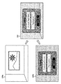
- FIG. 2 schematically shows an example of an image generated by the information processing apparatus 10 in the present embodiment.
- the main image 200a is an image that is mainly displayed, such as a game or a moving image.
- the additional image 200b is an image that is temporarily displayed as necessary, and the illustrated example includes a dialog box that allows the user to input an address and a password for login.
- the information processing apparatus 10 superimposes the additional image 200b including the dialog box on the main image 200a that was originally displayed, and generates and outputs a display image 202.
- the main image 200a by making the main image 200a visible through the additional image 200b in as large an area as possible, it is possible to suitably fuse necessary information without interrupting the world view of the main image 200a such as a game or a movie. it can. Furthermore, if the transparency of the additional image 200b is changed with time, it is possible to produce an effect that the dialog box gradually appears or disappears.
- the luminance F out of each pixel of the display image 202 can be determined by an alpha blend process represented by the following expression.
- F out (1 ⁇ ) Fb 1 + ⁇ Fb 2 (Formula 1)
- Fb 1 and Fb 1 are the luminances of the corresponding pixels in the main image 200a and the additional image 200b, respectively
- ⁇ is a general ⁇ value set for the corresponding pixel of the additional image 200b, that is, 0 or more indicating transparency. .0 or less.
- the color of the additional image 200b gradually becomes darker from the state where only the main image 200a is displayed, and finally the additional image 200b becomes opaque. Will be displayed. If the ⁇ value is an intermediate value larger than 0 and smaller than 1.0, the additional image 200b becomes translucent with a density corresponding to the numerical value, and the main image 200a can be seen through.
- the luminances Fb 1 and Fb 2 are set for each of the three channels. In the present embodiment, these are collectively referred to as luminances Fb 1 and Fb 2 .
- luminances Fb 1 and Fb 2 are collectively referred to as luminances Fb 1 and Fb 2 .
- the luminance values Fb 1 , Fb 2, and ⁇ value are set for each pixel, strictly speaking, although it depends on the two-dimensional position coordinates (x, y) on the image plane, Equation 1 applies to the pixels at the same position. The position coordinates are not shown because such calculation is assumed. The following description is also the same.
- Formula 1 is a calculation formula that does not consider the ⁇ value of the main image 200a. However, when the background image is further set and the transparency is also set for the main image 200a, the following formula is used for each pixel of the display image 202.
- the luminance F out can be calculated.
- ⁇ 1 and ⁇ 2 are ⁇ values respectively set for the pixels of the main image 200a and the additional image 200b.
- Expression 2 is expressed by Expression 1.
- the space that defines the luminance differs between the main image 200a and the additional image 200b.
- the additional image 200b is constantly generated by SDR, while the content to be processed is expressed by HDR.
- SDR and HDR even if they are the same 10-bit luminance signal, the luminance values indicated by the signals are different. Therefore, a signal expressed in another luminance space cannot be directly substituted into Equation 1 or Equation 2, and it is necessary to unify the luminance space at any stage before that. This is not limited to SDR / HDR, but is the same if the luminance space of the image to be alpha blended is different.
- the display device supports the HDR luminance range
- the luminance of the additional image 200b is represented by the HDR space
- the main image 200a is represented by You can keep a realistic view of the world expressed. In this embodiment, even if it is necessary to convert the luminance space of the image in this way, the influence on the color and brightness on the display is suppressed, and a good display is always performed.
- the present invention can be similarly applied in a situation where the luminance space of the image to be processed needs to be converted due to the composition processing or the performance of the display device, and the appearance should not be changed by the conversion processing.
- the present invention can be applied to a case where an image whose actual luminance range is within the SDR range needs to be redefined in the SDR luminance space.
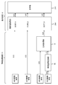
- FIG. 3 shows an image signal output from the information processing apparatus 10 and an outline of signal processing in the display device 16.
- the information processing apparatus 10 outputs a luminance signal of an image generated or decoded internally to the display device 16 (L1 or L3).
- This signal is obtained by converting an original luminance value into an electric signal having a predetermined number of bits such as 10 bits.
- an optical-electric transfer function (OETF) corresponding to each of HDR and SDR is used.
- the space defining the luminance signal thus output is HDR or SDR is displayed from the information processing apparatus 10 by using additional information of the signal or transmitting a mode switching request signal in advance.
- the device 16 is notified.
- the luminance value acquisition unit 208 converts the luminance signal into a luminance value using an electro-optical transfer function (EOTF).
- EOTF differs depending on whether the received image signal is HDR or SDR, and is shown as EOTF_H and EOTF_S in the figure.
- luminance values in different ranges such as 0 to 100 nit for SDR images and 0 to 10000 nit for HDR images can be obtained for each pixel.
- the display unit 210 having a display panel in the order of pixels (L2 or L4), an image is displayed in each luminance range.
- the luminance value acquisition unit 208 may select a luminance range so that the maximum luminance of the display device 16 is within the maximum luminance if the maximum luminance of the HDR image is higher than that. Adjust further.
- the luminance signal of the SDR image is The information is input to the luminance space conversion unit 66 in the information processing apparatus 10 (L6).
- the luminance space conversion unit 66 converts the signal into a luminance signal in the HDR space.
- the details of the conversion process may vary depending on the standard to be adopted, but basically, the luminance signal before conversion is obtained by compressing the SDR luminance space and associating it with a part of the HDR luminance space. It is made to fall within the partial range in the converted HDR space.
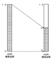
- FIG. 4 schematically shows how the luminance space is converted.
- the left rectangle represents the SDR luminance space
- the right rectangle represents the HDR luminance space.
- the entire luminance space is represented in the range of 0 to 1.0, but in actuality, the data is a predetermined number of bits such as 10 bits.
- the actual luminance represented in each luminance space is, for example, 0 to 100 nit for SDR and 0 to 10000 nit for HDR.
- the entire SDR luminance space (0 to 1.0) falls within a partial range 0 to R (where 0 ⁇ R ⁇ 1.0) in the HDR luminance space.
- the ratio R is set to, and the conversion rule is set under the conditions.
- the actual conversion rule may be a linear conversion in which the luminance signal in the SDR space is uniformly multiplied by the ratio R, or a non-linear monotonically increasing function may be used. You may prepare the lookup table which represented the conversion rule as a table. Further, the luminance signal thus converted may be further converted as necessary.
- the luminance signal (L7) of the image converted into the HDR space by the luminance space conversion unit 66 and the luminance signal (L5) of the image originally expressed in HDR are used as input values.
- the synthesis processing unit 72 performs alpha blending processing using Formula 1 or Formula 2.
- Fb 1, Fb 2 in Formula 1 or Formula 2 corresponding to the input of each L5, L7. It is assumed that the alpha value used for the alpha blend calculation is originally held by the synthesis processing unit 72 or is input separately.
- the information processing apparatus 10 outputs a luminance signal representing an image (for example, the display image 202 in FIG. 2) generated as a result of the alpha blend process to the display apparatus 16 as an HDR image (L8).
- the luminance value acquisition unit 208 of the display device 16 that has received the signal acquires a luminance value by EOTF corresponding to HDR and outputs the luminance value to the display unit 210 (L9). Accordingly, necessary information can be suitably displayed without deteriorating the world view of the content originally expressed in HDR and without changing the generation mechanism of the additional image assuming SDR.
- the conversion process may affect the display result on the display device 16. That is, even if the original SDR images are used, the color and brightness may change between the signal input from L3 and the signal input from L8 even if the change in transparency is ignored. obtain. This is because the final luminance acquisition processing in the luminance value acquisition unit 208 differs depending on the manufacturer of the display device and the like, and the reversibility of the luminance signal obtained through the luminance space conversion processing is not guaranteed.
- the color and brightness of the display image change depending on the presence / absence of the luminance space conversion process and the connected display device, which may cause the user to be uncomfortable or uncomfortable.
- the originally intended image is stable regardless of the presence or absence of the luminance space conversion processing and the display device. To be displayed.
- the same image expressed in each luminance space is actually displayed on the display device 16, and a user interface is provided so that the parameters can be adjusted while comparing them.
- the information processing device 10 adjusts, when the same image expressed in each luminance space is displayed, the difference between the luminance values actually output by the display device is acquired, and the parameters are set so that the difference is reduced. adjust.
- FIG. 5 shows the internal circuit configuration of the information processing apparatus 10.
- the information processing apparatus 10 includes a CPU (Central Processing Unit) 23, a GPU (Graphics Processing Unit) 24, and a main memory 26. These units are connected to each other via a bus 30.
- An input / output interface 28 is further connected to the bus 30.
- the input / output interface 28 includes a communication unit 32 including a peripheral device interface such as USB and IEEE1394, a wired or wireless LAN network interface connected to the network 8, a storage unit 34 such as a hard disk drive or a nonvolatile memory, and a display device.
- an input unit 38 for inputting data from the input device 14 and a recording medium driving unit 40 for driving a removable recording medium such as a magnetic disk, an optical disk or a semiconductor memory are connected.
- the CPU 23 controls the entire information processing apparatus 10 by executing the operating system stored in the storage unit 34.
- the CPU 23 also executes various programs read from the removable recording medium and loaded into the main memory 26 or downloaded via the communication unit 32.
- the communication unit 32 also establishes communication with an external device such as a server via the network 8 to acquire electronic content data such as a moving image or transmit data generated inside the information processing device 10. Also good.
- the GPU 24 has a function of a geometry engine and a function of a rendering processor, performs a drawing process according to a drawing command from the CPU 23, and stores display image data in a frame buffer (not shown).
- the display image stored in the frame buffer is converted into a video signal and output from the output unit 36, thereby causing the display device 16 to display the image.
- the main memory 26 is composed of RAM (Random Access Memory) and stores programs and data necessary for processing.
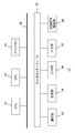
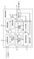
- FIG. 6 shows a functional block configuration of the information processing apparatus 10.
- Each functional block shown in FIG. 6 and FIG. 7 to be described later can be realized in terms of hardware by the configuration of the CPU, GPU, various memories, data bus, etc. shown in FIG.
- the program loaded in the memory is realized by a program that exhibits various functions such as a data input function, a data holding function, an arithmetic function, an image processing function, and a communication function. Therefore, it is understood by those skilled in the art that these functional blocks can be realized in various forms by hardware only, software only, or a combination thereof, and is not limited to any one.
- the information processing apparatus 10 includes an input information acquisition unit 50 that acquires input information from the input device 14, an information processing unit 52 that performs information processing according to a user operation such as a game, an image generation unit 54 that generates data of a main image, A superimposition data generation unit 56 that generates the additional image and ⁇ value data, a main image, an image synthesis unit 58 that synthesizes the additional image, and an image output unit 60 that outputs display image data to the display device 16 are included.
- a user operation such as a game
- an image generation unit 54 that generates data of a main image
- a superimposition data generation unit 56 that generates the additional image and ⁇ value data
- a main image an image synthesis unit 58 that synthesizes the additional image
- an image output unit 60 that outputs display image data to the display device 16 are included.
- the input information acquisition unit 50 is realized by the input unit 38, the CPU 23, and the like, and acquires data indicating the contents of the user operation from the input device 14.
- the user operation may be performed on a general information processing apparatus, such as selection of an application to be executed or content to be output, start / end of processing, command input, and the like.
- a display request for various information represented as an additional image is included.
- the input information acquisition unit 50 also acquires the contents of the user operation related to the adjustment in the mode for adjusting the parameters used for the conversion of the luminance space described above.
- the input information acquisition unit 50 may acquire data such as a captured image and an output value of the sensor.
- the input information acquisition unit 50 may also acquire electronic content data such as a moving image from a server via the network 8.
- the input information acquisition unit 50 appropriately supplies the acquired data to the information processing unit 52, the superimposed data generation unit 56, and the image composition unit 58 according to the contents.
- the information processing unit 52 is realized by the CPU 23, the main memory 26, and the like, and performs information processing such as a game based on data supplied from the input information acquisition unit 50. As described above, the content of the process performed by the information processing unit 52 is not particularly limited as long as it includes image display.
- the image generation unit 54 is realized by the GPU 24, the main memory 26, and the like, and generates main image data in accordance with a request from the information processing unit 52. For example, when the information processing unit 52 executes a game, the image generation unit 54 draws a game image according to a user operation, a sensor output value, or the like at a predetermined frame rate.
- the image generation unit 54 may decode and expand the moving image data designated by the information processing unit 52.
- the data of the moving image may be held in the information processing apparatus 10, may be streamed from the server via the network 8, or may be captured on the spot by the imaging apparatus.
- the data finally generated by the image generation unit 54 is a luminance signal expressed in one of the HDR and SDR spaces.
- the image generation unit 54 outputs the generated main image data to the image output unit 60.
- the image generation unit 54 outputs the generated main image data to the image composition unit 58.
- the superimposed data generation unit 56 is realized by the CPU 23, the GPU 24, the main memory 26, and the like, and generates additional image data as necessary.
- the additional image may be displayed at any time by being called by the user, or may be displayed at a timing determined by the information processing unit 52 according to the progress of the game or the moving image. Alternatively, it may be displayed constantly at one corner of the screen.
- image data held inside may be used, or data acquired by the input information acquisition unit 50 from an external device such as an imaging device or a server may be used.
- the data finally generated by the superimposed data generation unit 56 is a luminance signal expressed in the SDR space.
- the superimposition data generation unit 56 determines, for each pixel, an ⁇ value that determines the transparency with which the additional image is displayed, in association with the additional image.
- the additional image may gradually appear or disappear by changing the ⁇ value with time.
- the superimposed data generation unit 56 outputs the generated additional image data and the ⁇ image data having the ⁇ value as the pixel value to the image synthesis unit 58.
- the image generation unit 54 also outputs ⁇ image data to be set for the image to the image composition unit 58.
- the image composition unit 58 is realized by the CPU 23, the GPU 24, the main memory 26, and the like.
- the image composition unit 58 may be realized as an image composition device that superimposes data of two images and outputs a display image.
- the image composition unit 58 includes a superimposition data acquisition unit 62 that acquires superimposition data, a main image data acquisition unit 64 that acquires main image data, a luminance space conversion unit 66 that converts a luminance space, and an alpha blend process.
- a synthesis processing unit 72 that generates display image data.
- the superimposition data acquisition unit 62 acquires the luminance signal of the additional image and the ⁇ image data having the ⁇ value as the pixel value from the superimposition data generation unit 56.
- the main image data acquisition unit 64 acquires the luminance signal of the main image from the image generation unit 54 and supplies it to the synthesis processing unit 72.
- the main image data acquisition unit 64 determines whether or not it is necessary to convert the luminance space of the additional image based on the luminance space of the main image specified by data analysis or the like.
- the main image data acquisition unit 64 determines that the luminance space of the additional image needs to be converted.
- the present embodiment is not limited to this, and if the space defining the brightness is different, it is determined that the conversion is necessary regardless of the difference in SDR / HDR.
- the additional image is generated by an algorithm somewhat fixed in the information processing apparatus, while the main image is created with a high degree of freedom on the content providing side, such a situation can often occur.
- the main image data acquisition unit 64 When it is necessary to convert the luminance space, the main image data acquisition unit 64 notifies the superimposed data acquisition unit 62 to that effect.
- the superimposition data acquisition unit 62 notified of the luminance space of the main image from the main image data acquisition unit 64 may determine the necessity of conversion in view of both the main image and the additional image.
- the superimposition data acquisition unit 62 switches the supply destination of the acquired data depending on whether or not the luminance space needs to be converted. Specifically, when it is not necessary to convert the luminance space, the superimposed data acquisition unit 62 supplies the acquired data to the synthesis processing unit 72 as it is. When it is necessary to convert the luminance space, the superimposed data acquisition unit 62 supplies the acquired data to the luminance space conversion unit 66.
- the composition processing unit 72 displays the data and the main image data acquired from the main image data acquisition unit 64 by substituting the data into the above Equation 1 or Equation 2.
- the pixel value of the image is calculated. In the assumed example, this situation occurs when both the main image and the additional image are luminance signals defined in the SDR space, so the calculated pixel value is also the luminance signal in the SDR space.
- the pixel value of the display image can be calculated as it is. In this case, the calculated pixel value is a luminance signal in the HDR space.
- the luminance space conversion unit 66 has a function equivalent to that of the luminance space conversion unit 66 shown in FIG. 3 and converts the luminance space of the additional image supplied from the superimposed data acquisition unit 62.
- the luminance signal defined in the SDR space is converted into the HDR signal.
- the luminance space conversion unit 66 further provides an interface for accepting adjustment of parameters used for conversion from the user. Specifically, an adjustment image defined in the SDR luminance space is prepared and stored in an internal memory. Then, the image displayed on the display device 16 can be compared between the case where the image is output as the SDR luminance signal and the case where the image is output after being converted into the HDR luminance signal.
- the user outputs the SDR luminance signal as it is, converts the displayed image into an HDR luminance signal, outputs the displayed image, and performs an adjustment operation until the displayed image has a substantially equivalent appearance. If the optimum parameters are determined in this way, in the subsequent processing, regardless of the processing in the display device 16 and whether the main image is SDR or HDR, the same color and brightness are used. The additional image can be displayed in a superimposed manner.
- the luminance space conversion unit 66 may adjust the parameter itself.
- the brightness when the display device 16 actually causes the display panel to emit light is output between the case where the adjustment image is output as the SDR luminance signal and the case where the image is output after being converted into the HDR luminance signal.
- the luminance value output from the luminance value acquisition unit 208 shown in FIG. 3 is fed back to the information processing apparatus 10, and the luminance space conversion unit 66 adjusts the parameters so that the difference in luminance value in each luminance space becomes small.
- the luminance value may be compared by a predetermined pixel, or may be compared by a statistical process such as comparing the average luminance value of the entire image for each color. Those skilled in the art will understand that various methods for numerically comparing the overall color and brightness of an image can be considered.
- the luminance space conversion unit 66 When a condition that requires adjustment is satisfied, such as when the display device 16 is newly connected to the information processing apparatus 10, the luminance space conversion unit 66 notifies the user via the image output unit 60 and the display device 16. Make a notification. When the user inputs an instruction to start adjustment accordingly, the mode shifts to a parameter adjustment mode. Alternatively, the adjustment mode may be activated when the user feels necessity. Regardless of the adjustment by the user or the adjustment by the luminance space conversion unit 66, the parameters determined after the adjustment are held in the internal memory, and thereafter, the luminance space is converted using the parameters.
- the luminance space converting unit 66 supplies the additional image signal and the ⁇ image data obtained by converting the luminance space using the adjusted parameters to the synthesis processing unit 72. Even when data is acquired from the luminance space conversion unit 66, the composition processing unit 72 substitutes the data and the main image data acquired from the main image data acquisition unit 64 into the above-described Expression 1 or Expression 2 to display images. The pixel value of is calculated. In this case, since both the main image and the additional image are luminance signals defined in the HDR space, the calculated pixel value is also an HDR space luminance signal.
- the composition processing unit 72 has a function equivalent to that of the composition processing unit 72 shown in FIG.
- the composition processing unit 72 outputs the calculated result to the image output unit 60.
- the image output unit 60 is realized by the GPU 24, the main memory 26, the output unit 36, and the like.
- the image output unit 60 receives the main image data supplied from the image generation unit 54 or the image data superimposed with the additional image supplied from the image composition unit 58. And sequentially output to the display device 16 at an appropriate timing.
- the image output unit 60 also acquires the adjustment screen data from the luminance space conversion unit 66 and outputs it to the display device 16 in the adjustment mode of the parameters used for conversion of the luminance space.
- the image output unit 60 further acquires information on the actual luminance value when the adjustment image is displayed in each luminance space from the display device 16, and the luminance space This is supplied to the conversion unit 66.
- the luminance value acquisition unit 208 uses an appropriate EOTF depending on whether the luminance signal of the transmitted image is HDR or SDR. Get the brightness of the pixel. An image is displayed in the HDR or SDR luminance range by outputting line by line from the display panel of the display unit 210.
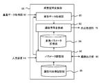
- FIG. 7 shows the configuration of the functional blocks of the luminance space conversion unit 66 in more detail.
- the luminance space conversion unit 66 includes a linear data acquisition unit 80, a luminance signal conversion unit 82, a conversion parameter storage unit 84, a parameter adjustment unit 86, and an adjustment image storage unit 88.
- the linear data acquisition unit 80 acquires, from the superimposed data acquisition unit 62, luminance signal data and ⁇ image data of an image that needs to be converted in the luminance space.
- the luminance signal is generally subjected to non-linear conversion such as gamma correction. Therefore, a signal having a linear change with respect to the original luminance is obtained by performing the reverse conversion.
- the luminance signal converter 82 converts the luminance signal thus obtained into a luminance signal in the HDR space. That is, as described with reference to FIG. 4, the conversion is performed according to the rules set in the direction of compressing the original signal. In the conversion, the parameters stored in the conversion parameter storage unit 84 are referred to.
- the finally obtained luminance signal is, for example, ITU-R BT.
- the parameter adjustment unit 86 receives an adjustment operation of the parameter from the user in the adjustment mode of the parameter used for conversion of the luminance space. Alternatively, it performs parameter adjustment processing by itself. Both may be implemented alternatively, or both may be selectable as being feasible. In the former case, as described above, the parameter adjustment unit 86 converts the adjustment image data stored in the adjustment image storage unit 88 into the HDR luminance space when the SDR luminance signal is displayed as it is. The display image can be compared with the case where it is displayed.
- the parameter adjustment unit 86 causes the linear data acquisition unit 80 and the luminance signal conversion unit 82 to perform the same processing as described above on the image data for adjustment. Since there is no need for the synthesis process in the adjustment mode, the parameter adjustment unit 86 directly inputs the image signal represented in each luminance space to the image output unit 60 and causes the display device 16 to output it.
- the data output here corresponds to the data of L3 and L7 shown in FIG.
- the display device 16 converts the luminance signal expressed in the SDR space or the HDR space into a luminance value by EOTF corresponding to each luminance space, and displays the luminance value.
- the parameter adjusting unit 86 changes the parameters used for the conversion of the luminance space at any time according to the adjustment operation from the user and reflects them in the display. Then, the parameters at the time when the user performs the confirmation operation are stored in the conversion parameter storage unit 84 so that they can be referred to in the subsequent conversion processing.
- the process for causing the display device 16 to display the adjustment image represented in each luminance space is the same.
- the actual luminance value when each image is displayed as described above is acquired from the display device 16, and the parameter when the difference is minimized is stored in the conversion parameter storage unit 84.
- the parameter to be adjusted by the parameter adjusting unit 86 is not limited as long as it affects the conversion rule of the luminance space and can adjust the color and brightness after conversion.
- the ratio R in the HDR luminance space may be associated with the upper limit of the SDR luminance space shown in FIG.
- the transfer function and the color space differ between an environment for processing an SDR image and an environment for processing an HDR image.
- the actually displayed image has a unique color depending on the manufacturer of the display device, and therefore it is difficult to logically derive an appropriate ratio R that does not change the impression before and after conversion of the luminance space. .
- the ratio R can be adjusted according to the actual situation, so that the color given to the entire image to be converted can be obtained without adjusting the conversion rule of the intermediate value of the luminance signal in detail
- the impression of taste and brightness can be changed efficiently. That is, by changing the ratio R, the entire function can be changed even if the conversion rule is a non-linear function.
- the adjustment parameter is not intended to be limited to the ratio R, but may be one or more parameters included in or affecting the conversion function.
- a plurality of conversion lookup tables may be prepared, and the table to be used may be changed according to the adjustment.
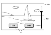
- FIG. 8 illustrates an adjustment screen that the parameter adjustment unit 86 presents to the user in a parameter adjustment mode used for conversion of the luminance space.
- the adjustment screen 100 displays an adjustment image in the entire area, and displays a luminance space switching button 102 and an adjustment slide bar 106 as a GUI (Graphical User Interface).
- the adjustment image is a predetermined photographed image, a drawn image by computer graphics, or the like defined in the SDR luminance space. Simpler colors and graphic patterns may be used.
- the parameter adjusting unit 86 When the button labeled “SDR” among the luminance space switching buttons 102 is operated, the parameter adjusting unit 86 outputs the adjustment image as it is in the SDR luminance space. This corresponds to the output of L3 in FIG. In this case, the display device 16 processes and displays the acquired data as SDR data. On the other hand, when a button labeled “HDR” among the luminance space switching buttons 102 is operated, the parameter adjustment unit 86 converts the adjustment image into data in the HDR luminance space and outputs the data.
- the display device 16 processes and displays the acquired data as HDR data.
- the adjustment slide bar 106 can be operated only when an image in the HDR luminance space is displayed. The user compares the image displayed when the “HDR” button is operated with the image displayed when the “SDR” button is operated, and adjusts if the impression of color and brightness is different. The handle of the slide bar 106 is moved up and down.
- the parameter adjustment unit 86 changes the parameter to be adjusted, such as the ratio R, according to the adjustment operation, converts the luminance space again, and immediately displays it on the display device 16.
- the user repeats the adjustment operation while viewing the changing image, and when no difference is felt between the two images, the user performs a confirmation operation by an operation means (not shown).
- the parameter adjustment unit 86 stores the parameter at that time in the conversion parameter storage unit 84.
- the luminance signal conversion unit 82 uses the stored parameters in the subsequent conversion processing.
- the adjustment screen shown in FIG. 8 is merely an example, and the specific means is not limited as long as the switching of the luminance space and the adjustment of the parameters can be performed intuitively and easily.
- these means may be assigned to the hardware key of the input device 14. Further, depending on the parameter to be adjusted, it does not cause a continuous change like a slide bar, but may be adjusted using a GUI or operation means for switching the selection target from a plurality of candidates.
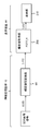
- FIG. 9 shows an outline of an image signal output from the information processing apparatus 10 and signal processing in the display apparatus 16 in such a case.
- the luminance signal of the image is directly input to the luminance space conversion unit 66 (L10).
- the luminance space conversion unit 66 converts the acquired luminance signal into a luminance signal in the HDR space and outputs the luminance signal to the display device 16 (L11).
- the function of the luminance space conversion unit 66 is the same as that described with reference to FIG. Therefore, the converted parameter stored in the conversion parameter storage unit 84 is used for the conversion.
- the luminance value acquisition unit 208 of the display device 16 converts the acquired luminance signal into a luminance value using EOTF corresponding to HDR, and sequentially outputs the luminance signal to the display unit 210 (L12).
- the data in which the original image is expressed in SDR can be processed in the display device 16 in the same manner as the HDR image, and the displayed image follows the original color and brightness. It will be a thing.
- individual content such as a game expressed in SDR can be displayed on an HDR-compatible display device without the need to switch processing on the display device, and is not affected by differences in display processing. It can be displayed in the same way.
- individual content such as a game expressed in SDR
- it can be displayed in the same way.
- by holding and sharing the optimum conversion parameters on the information processing apparatus side it is possible to save time and effort such as setting parameters inside individual contents in accordance with the assumed display apparatus.
- the parameters used for the conversion can be adjusted according to the actual display state.
- a user interface is provided in which a display image processed in the original luminance space is actually compared with an image displayed through the luminance space conversion process, and parameters can be adjusted with an easy operation.
- the actual brightness of the displayed image is acquired from the display device, and the parameters are adjusted on the information processing device side.
- an additional image expressed in SDR can be superimposed and displayed with the same appearance and transparency.
- the parameter optimized by one adjustment can be used in common regardless of the content, it is possible to easily correspond to a display device assuming various luminance spaces without setting the parameter inside the content. .
- the present invention can be used for various information processing devices such as game devices, image processing devices, portable terminals, and electronic content processing devices, and information processing systems including them.
Landscapes
- Engineering & Computer Science (AREA)
- Physics & Mathematics (AREA)
- General Physics & Mathematics (AREA)
- Theoretical Computer Science (AREA)
- Computer Hardware Design (AREA)
- Multimedia (AREA)
- Signal Processing (AREA)
- Controls And Circuits For Display Device (AREA)
- Image Processing (AREA)
- Television Receiver Circuits (AREA)
Abstract
A luminance space conversion unit 66 of an information processing device converts an image signal represented in a luminance space corresponding to a SDR into a signal represented in a luminance space corresponding to a HDR, and outputs the converted signal to a synthesis processing unit 72 that performs alpha blending with an image in the HDR. In an adjustment mode, a parameter adjustment unit 86 displays an adjustment image presented in the SDR on a display device and adjusts a parameter to be used for converting the luminance space so that there is little change in the display image before and after converting the luminance space. The parameter is stored in a conversion parameter storage unit 84 after the adjustment and is used when a luminance signal conversion unit 82 performs the conversion.
Description
本発明は、表示装置に画像を表示させる情報処理装置およびそれが行う画像処理方法に関する。
The present invention relates to an information processing apparatus that displays an image on a display device and an image processing method performed by the information processing apparatus.
従来、テレビジョン放送や配信動画などの映像表示において画質を向上させるための様々な技術が開発されてきた。近年では解像度や色域を向上させる技術に加え、輝度のレンジを拡大したHDR(High Dynamic Range)の信号を処理する技術が普及しつつある。従来のSDR(Standard Dynamic Range)と比較し、HDRは輝度の許容範囲が100倍程になるため、太陽光の反射光など実世界で眩しいと感じるような対象を、画像上でもよりリアルに表現することができる。テレビジョン放送や配信動画のみならず、ゲーム画像などコンピュータグラフィクスの世界でも、HDRで表現することによって仮想世界により臨場感を与えられる(例えば特許文献1参照)。
Conventionally, various techniques for improving the image quality in video display such as television broadcasting and distribution video have been developed. In recent years, in addition to techniques for improving resolution and color gamut, techniques for processing HDR (High Dynamic Range) signals with an expanded luminance range are becoming widespread. Compared with the conventional SDR (Standard Dynamic Range), HDR has an allowable range of brightness of about 100 times, so objects that feel dazzling in the real world, such as reflected sunlight, can be expressed more realistically on the image. can do. In the world of computer graphics such as game images as well as television broadcasts and distributed videos, the virtual world can give a sense of realism when expressed in HDR (see, for example, Patent Document 1).
HDRの輝度レンジに対応した表示装置を用いても、表示させる画像の全てがHDRで表現されているとは限らない。例えばヘルプ画面やコントロールパネルなど、ゲーム装置や再生装置側で提供する付加的な画像は、コンテンツの画像とは独立に、SDRで表現されることが考えられる。コンテンツ自体がSDRで表現されている場合も多い。HDRとSDRでは、輝度値とそれを表す電気信号との間での変換規則、規格が異なる。また表示装置メーカーが独自の処理でディスプレイの発色を制御していることもある。結果として、様々な変換処理を経て表示される画像が、コンテンツ、画像処理装置、表示装置の組み合わせに依存して、本来のデザインと異なった色味や明るさとなってしまうことがあり得る。
Even if a display device that supports the HDR luminance range is used, not all images to be displayed are represented in HDR. For example, an additional image provided on the game device or playback device side, such as a help screen or a control panel, can be expressed in SDR independently of the content image. In many cases, the content itself is expressed in SDR. HDR and SDR have different conversion rules and standards between the luminance value and the electrical signal representing it. In addition, display device manufacturers may control the coloration of the display using unique processing. As a result, an image displayed through various conversion processes may have a color and brightness different from the original design depending on the combination of the content, the image processing apparatus, and the display apparatus.
本発明はこうした課題に鑑みてなされたものであり、その目的は、画像作成時に想定された輝度レンジによらず、常に好適な状態で画像を表示できる技術を提供することにある。
The present invention has been made in view of these problems, and an object of the present invention is to provide a technique capable of always displaying an image in a suitable state regardless of the luminance range assumed at the time of image creation.
本発明のある態様は情報処理装置に関する。この情報処理装置は、第1の輝度空間で表された画像の信号を取得する画像データ取得部と、画像の信号を第2の輝度空間で表した信号に変換する輝度空間変換部と、いずれかの輝度空間で表された画像の信号を表示装置に出力する画像出力部と、を備え、輝度空間変換部は、信号の変換に用いるパラメータを、表示装置における表示の状態に応じた所定の情報に基づき調整するパラメータ調整部を備え、調整後のパラメータを用いて信号を変換することを特徴とする。
An aspect of the present invention relates to an information processing apparatus. The information processing apparatus includes an image data acquisition unit that acquires an image signal represented in a first luminance space, a luminance space conversion unit that converts an image signal into a signal represented in a second luminance space, An image output unit that outputs an image signal represented in the luminance space to a display device, and the luminance space conversion unit sets a parameter used for signal conversion to a predetermined value corresponding to a display state on the display device. A parameter adjustment unit that adjusts based on information is provided, and a signal is converted using the adjusted parameter.
ここで「輝度空間」は、輝度の値を所定ビット数の信号で表す際の変換規則を決定づける空間であり、「第1の輝度空間」および「第2の輝度空間」は例えば、SDRの輝度レンジに対応する輝度空間、HDRの輝度レンジに対応する輝度空間である。ただし第1、第2の輝度空間はこれに限らず、各輝度空間で表すことのできる輝度の最大レンジが異なれば、当該レンジの具体値は限定されない。
Here, the “luminance space” is a space that determines a conversion rule when the luminance value is represented by a signal having a predetermined number of bits, and the “first luminance space” and the “second luminance space” are, for example, the luminance of the SDR. The luminance space corresponding to the range and the luminance space corresponding to the HDR luminance range. However, the first and second luminance spaces are not limited to this, and the specific values of the ranges are not limited as long as the maximum luminance range that can be expressed in each luminance space is different.
本発明の別の態様は画像処理方法に関する。この画像処理方法は情報処理装置が、第1の輝度空間で表された画像の信号を第2の輝度空間で表した信号に変換するのに用いるパラメータを、表示装置における表示の状態に応じた所定の情報に基づき調整するステップと、第1の輝度空間で表された表示対象の画像の信号を取得するステップと、取得した表示対象の画像の信号を、調整後のパラメータを用いて第2の輝度空間で表した信号に変換するステップと、変換された表示対象の画像の信号を表示装置に出力するステップと、を含むことを特徴とする。
Another aspect of the present invention relates to an image processing method. In this image processing method, the information processing apparatus uses parameters used to convert the signal of the image represented in the first luminance space into the signal represented in the second luminance space according to the display state on the display device. A step of adjusting based on predetermined information; a step of acquiring a signal of an image to be displayed represented in the first luminance space; and a second step of adjusting the acquired signal of the image to be displayed using a parameter after adjustment. And a step of converting the signal of the image to be displayed to a display device.
なお、以上の構成要素の任意の組合せ、本発明の表現を方法、装置、システム、コンピュータプログラム、コンピュータプログラムを記録した記録媒体などの間で変換したものもまた、本発明の態様として有効である。
Note that any combination of the above-described components, and the expression of the present invention converted between a method, an apparatus, a system, a computer program, a recording medium on which the computer program is recorded, and the like are also effective as an aspect of the present invention. .
本発明によると、画像作成時に想定された輝度レンジによらず、常に好適な状態で画像を表示できる。
According to the present invention, an image can always be displayed in a suitable state regardless of the luminance range assumed at the time of image creation.
図1は本実施の形態における情報処理システムの構成例を示す。情報処理システムは、情報処理装置10、入力装置14、表示装置16を含む。図示するように情報処理装置10はインターネットなどのネットワーク8を介して各種コンテンツを提供するサーバ等と接続可能としてもよい。入力装置14はコントローラ、キーボード、マウス、ジョイスティック、タッチパッドなどユーザ操作が可能な一般的な入力装置のほか、ユーザなど実世界を撮影する撮像装置、音声を取得するマイク、各種物理値を検出するセンサや、それらのうちいずれかの組み合わせでもよい。
FIG. 1 shows a configuration example of an information processing system in the present embodiment. The information processing system includes an information processing device 10, an input device 14, and a display device 16. As illustrated, the information processing apparatus 10 may be connectable to a server or the like that provides various contents via a network 8 such as the Internet. The input device 14 detects general physical devices such as a controller, a keyboard, a mouse, a joystick, and a touch pad, an imaging device that captures the real world such as a user, a microphone that acquires sound, and various physical values. A sensor or any combination thereof may be used.
表示装置16は、画像を表示する液晶ディスプレイ、プラズマディスプレイ、有機ELディスプレイなどで実現する。さらに音声を出力するスピーカを備えていてもよい。入力装置14および表示装置16は、情報処理装置10に有線ケーブルで接続されてよく、また無線LAN(Local Area Network)などにより無線接続されてもよい。また入力装置14、表示装置16、情報処理装置10の外観形状は図示するものに限らず、例えばそれらのうち2つ以上が一体的に形成されていてもよい。
The display device 16 is realized by a liquid crystal display, a plasma display, an organic EL display, or the like that displays an image. Further, a speaker that outputs sound may be provided. The input device 14 and the display device 16 may be connected to the information processing device 10 by a wired cable, or may be wirelessly connected by a wireless LAN (Local Area Network) or the like. Further, the external shapes of the input device 14, the display device 16, and the information processing device 10 are not limited to those illustrated in the drawings, and for example, two or more of them may be integrally formed.
情報処理装置10は、ユーザ操作に係る信号を入力装置14から受信し、それに応じた処理を実施して表示画像のデータを生成し、表示装置16に出力する。情報処理装置10はゲーム機、パーソナルコンピュータ、タブレット端末、携帯端末、携帯電話などのいずれであってもよい。そのような情報処理装置10の形態や、ユーザが選択したアプリケーションなどに応じて、情報処理装置10が行う処理の内容は様々であってよい。
The information processing apparatus 10 receives a signal related to a user operation from the input apparatus 14, performs processing according to the signal, generates display image data, and outputs the display image data to the display apparatus 16. The information processing apparatus 10 may be a game machine, a personal computer, a tablet terminal, a mobile terminal, a mobile phone, or the like. The contents of the processing performed by the information processing apparatus 10 may vary depending on the form of the information processing apparatus 10 and the application selected by the user.
例えば情報処理装置10は、ユーザが指定した電子ゲームをユーザ操作に応じて進捗させ、そのゲーム画面のデータを所定のフレームレートで生成し出力する。あるいはネットワーク8を介して動画のデータをサーバから取得し、それを逐次復号して出力してもよい。このように情報処理装置10の使用目的は様々であってよく、それに応じて実施する情報処理の内容も異なるため、詳細な説明は省略する。以後、そのような情報処理の結果として生成されたコンテンツの画像や、提示すべき情報を表した画像などを好適に表示させる手法に主眼を置いて説明する。
For example, the information processing apparatus 10 advances an electronic game designated by the user according to a user operation, and generates and outputs data of the game screen at a predetermined frame rate. Alternatively, moving image data may be acquired from the server via the network 8, and sequentially decoded and output. As described above, the purpose of use of the information processing apparatus 10 may be various, and the content of information processing to be performed differs accordingly. Hereinafter, a description will be given with a focus on a technique for suitably displaying an image of content generated as a result of such information processing, an image representing information to be presented, and the like.
図2は、本実施の形態において情報処理装置10が生成する画像の一例を模式的に示している。この例においてメイン画像200aは例えばゲームや動画など、主として表示される画像である。付加画像200bは必要に応じて一時的に表示される画像であり、図示する例はユーザにログインのためのアドレスとパスワードを入力させるダイアログボックスを含む。このようなダイアログボックスを表示させる必要が生じると、情報処理装置10は、元から表示させていたメイン画像200aにダイアログボックスを含む付加画像200bを重畳させ、表示画像202を生成して出力する。
FIG. 2 schematically shows an example of an image generated by the information processing apparatus 10 in the present embodiment. In this example, the main image 200a is an image that is mainly displayed, such as a game or a moving image. The additional image 200b is an image that is temporarily displayed as necessary, and the illustrated example includes a dialog box that allows the user to input an address and a password for login. When such a dialog box needs to be displayed, the information processing apparatus 10 superimposes the additional image 200b including the dialog box on the main image 200a that was originally displayed, and generates and outputs a display image 202.
このときなるべく広い領域で、付加画像200bを介してメイン画像200aが透けて見えるようにすることで、ゲームや動画などメイン画像200aの世界観が途切れることなく必要な情報を好適に融合させることができる。さらに付加画像200bの透明度を時間変化させれば、ダイアログボックスが徐々に出現したり消滅したりする演出もできる。
At this time, by making the main image 200a visible through the additional image 200b in as large an area as possible, it is possible to suitably fuse necessary information without interrupting the world view of the main image 200a such as a game or a movie. it can. Furthermore, if the transparency of the additional image 200b is changed with time, it is possible to produce an effect that the dialog box gradually appears or disappears.
複数の画像を重ねて表示させるケースは、図示する例以外にも様々に考えられることは当業者には理解されるところである。例えばレースゲームの場合、ドライバの視野を示すメイン画像に、コース全体を俯瞰した付加画像を追加で表示することが考えられる。映画を表示させる場合は、あらすじや出演者などの書誌情報を示す画像や、再生、一時停止、早送りなどの操作パネルを付加的に表示することが考えられる。
It will be understood by those skilled in the art that various cases other than the illustrated example can be considered in which a plurality of images are displayed in a superimposed manner. For example, in the case of a racing game, it may be possible to additionally display an additional image overlooking the entire course on the main image showing the driver's field of view. When displaying a movie, it may be possible to additionally display an image indicating bibliographic information such as a synopsis or a performer, or an operation panel such as playback, pause, or fast-forward.
このような表示画像202を生成する場合、次式で表されるアルファブレンド処理により、表示画像202の各画素の輝度Foutを決定できる。
Fout=(1-α)Fb1+αFb2 (式1)
ここでFb1、Fb1はそれぞれ、メイン画像200a、付加画像200bにおける対応する画素の輝度、αは付加画像200bの当該画素に設定された一般的なα値、すなわち透過度を示す0以上1.0以下の値である。 When such adisplay image 202 is generated, the luminance F out of each pixel of the display image 202 can be determined by an alpha blend process represented by the following expression.
F out = (1−α) Fb 1 + αFb 2 (Formula 1)
Here, Fb 1 and Fb 1 are the luminances of the corresponding pixels in themain image 200a and the additional image 200b, respectively, and α is a general α value set for the corresponding pixel of the additional image 200b, that is, 0 or more indicating transparency. .0 or less.
Fout=(1-α)Fb1+αFb2 (式1)
ここでFb1、Fb1はそれぞれ、メイン画像200a、付加画像200bにおける対応する画素の輝度、αは付加画像200bの当該画素に設定された一般的なα値、すなわち透過度を示す0以上1.0以下の値である。 When such a
F out = (1−α) Fb 1 + αFb 2 (Formula 1)
Here, Fb 1 and Fb 1 are the luminances of the corresponding pixels in the
例えば画像全体においてα値を0から1.0まで変化させると、メイン画像200aのみが表示されている状態から徐々に付加画像200bの色が濃くなっていき、最終的に付加画像200bが不透明に表示されることになる。α値を0より大きく1.0より小さい中間値とすれば、付加画像200bがその数値に応じた濃さで半透明の状態となり、メイン画像200aが透けて見えることになる。
For example, when the α value is changed from 0 to 1.0 in the entire image, the color of the additional image 200b gradually becomes darker from the state where only the main image 200a is displayed, and finally the additional image 200b becomes opaque. Will be displayed. If the α value is an intermediate value larger than 0 and smaller than 1.0, the additional image 200b becomes translucent with a density corresponding to the numerical value, and the main image 200a can be seen through.
なおメイン画像200a、付加画像200bがRGB画像であれば、輝度Fb1、Fb2は当該3チャンネルのそれぞれに設定されるが、本実施の形態ではそれらを総称して輝度Fb1、Fb2と表す。また輝度Fb1、Fb2およびα値はそれぞれ、画素ごとに設定されるため、厳密には画像平面における2次元の位置座標(x,y)に依存するが、式1は同じ位置の画素に係る計算を前提としているため位置座標は示していない。以下の記載も同様である。
If the main image 200a and the additional image 200b are RGB images, the luminances Fb 1 and Fb 2 are set for each of the three channels. In the present embodiment, these are collectively referred to as luminances Fb 1 and Fb 2 . To express. Further, since the luminance values Fb 1 , Fb 2, and α value are set for each pixel, strictly speaking, although it depends on the two-dimensional position coordinates (x, y) on the image plane, Equation 1 applies to the pixels at the same position. The position coordinates are not shown because such calculation is assumed. The following description is also the same.
式1はメイン画像200aのα値を考慮しない計算式であったが、さらに背景画像を設定するなどし、メイン画像200aにも透過度を設定する場合、下式により表示画像202の各画素の輝度Foutを計算できる。
αout=(1-α2)α1+α2
Fout=(α1(1-α2)Fb1+α2Fb2 )/ αout (式2)
ここでα1、α2は、メイン画像200a、付加画像200bの各画素にそれぞれ設定されたα値である。なおメイン画像200aが不透明のとき、すなわちα1=1のとき、式2は式1で表される。 Formula 1 is a calculation formula that does not consider the α value of themain image 200a. However, when the background image is further set and the transparency is also set for the main image 200a, the following formula is used for each pixel of the display image 202. The luminance F out can be calculated.
α out = (1−α 2 ) α 1 + α 2
F out = (α 1 (1-α 2 ) Fb 1 + α 2 Fb 2 ) / α out (Formula 2)
Here, α 1 and α 2 are α values respectively set for the pixels of themain image 200a and the additional image 200b. When the main image 200a is opaque, that is, when α 1 = 1, Expression 2 is expressed by Expression 1.
αout=(1-α2)α1+α2
Fout=(α1(1-α2)Fb1+α2Fb2 )/ αout (式2)
ここでα1、α2は、メイン画像200a、付加画像200bの各画素にそれぞれ設定されたα値である。なおメイン画像200aが不透明のとき、すなわちα1=1のとき、式2は式1で表される。 Formula 1 is a calculation formula that does not consider the α value of the
α out = (1−α 2 ) α 1 + α 2
F out = (α 1 (1-α 2 ) Fb 1 + α 2 Fb 2 ) / α out (Formula 2)
Here, α 1 and α 2 are α values respectively set for the pixels of the
このような構成において、輝度を定義する空間が、メイン画像200aと付加画像200bで異なる場合を考える。例えばコンテンツの処理装置において、付加画像200bを定常的にSDRで生成する一方、処理対象のコンテンツはHDRで表現されている場合がこれにあたる。SDRとHDRでは、同じ10bitの輝度信号であっても、それが指す輝度の値が異なる。そのため別の輝度空間で表された信号をそのまま式1、あるいは式2に代入することはできず、その前のいずれかの段階で輝度空間を統一する必要がある。このことはSDR/HDRに限らず、アルファブレンドの対象となる画像の輝度空間が異なれば同様である。
Suppose that in such a configuration, the space that defines the luminance differs between the main image 200a and the additional image 200b. For example, in the content processing apparatus, the additional image 200b is constantly generated by SDR, while the content to be processed is expressed by HDR. In SDR and HDR, even if they are the same 10-bit luminance signal, the luminance values indicated by the signals are different. Therefore, a signal expressed in another luminance space cannot be directly substituted into Equation 1 or Equation 2, and it is necessary to unify the luminance space at any stage before that. This is not limited to SDR / HDR, but is the same if the luminance space of the image to be alpha blended is different.
メイン画像200aがHDR、付加画像200bがSDRで表現されており、表示装置がHDRの輝度レンジに対応している場合、付加画像200bの輝度をHDRの空間で表すようにすると、メイン画像200aで表現されているリアルな世界観を保つことができる。本実施の形態では、このように画像の輝度空間を変換する必要が生じても、表示上での色味や明るさなどへの影響を抑え、常に良好な表示がなされるようにする。
When the main image 200a is represented by HDR and the additional image 200b is represented by SDR, and the display device supports the HDR luminance range, if the luminance of the additional image 200b is represented by the HDR space, the main image 200a is represented by You can keep a realistic view of the world expressed. In this embodiment, even if it is necessary to convert the luminance space of the image in this way, the influence on the color and brightness on the display is suppressed, and a good display is always performed.
以後、主に付加画像の輝度空間をSDRからHDRに変換するケースについて説明するが、本実施の形態の適用範囲はこれに限らない。すなわち処理対象の画像の輝度空間を、合成処理や表示装置の性能に起因して変換する必要があり、かつ変換処理によって見た目が変化しないようにすべき状況においては同様に適用できる。例えばHDRの輝度空間で定義されていても、実際の輝度のレンジがSDRの範囲に収まっている画像を、SDRの輝度空間で定義し直す必要がある場合などにも適用できる。
Hereinafter, a case where the luminance space of the additional image is mainly converted from SDR to HDR will be described, but the scope of application of the present embodiment is not limited to this. That is, the present invention can be similarly applied in a situation where the luminance space of the image to be processed needs to be converted due to the composition processing or the performance of the display device, and the appearance should not be changed by the conversion processing. For example, even if the image is defined in the HDR luminance space, the present invention can be applied to a case where an image whose actual luminance range is within the SDR range needs to be redefined in the SDR luminance space.
図3は情報処理装置10から出力される画像の信号と、表示装置16における信号処理の概略を示している。まずHDRの画像、あるいはSDRの画像を独立して表示させる場合、情報処理装置10は内部で生成したり復号したりしてなる画像の輝度信号を表示装置16へ出力する(L1またはL3)。この信号は、本来の輝度値を、10bitなど所定ビット数の電気信号に変換したものである。変換にはHDR、SDRのそれぞれに対応する光-電気伝達関数(OETF:Optical-Electro Transfer Function)が用いられる。
FIG. 3 shows an image signal output from the information processing apparatus 10 and an outline of signal processing in the display device 16. First, when displaying an HDR image or an SDR image independently, the information processing apparatus 10 outputs a luminance signal of an image generated or decoded internally to the display device 16 (L1 or L3). This signal is obtained by converting an original luminance value into an electric signal having a predetermined number of bits such as 10 bits. For the conversion, an optical-electric transfer function (OETF) corresponding to each of HDR and SDR is used.
そのように出力された輝度信号を定義する空間がHDRであるかSDRであるかは、当該信号の付加情報としたり、モード切り替え要求信号を事前に送信したりすることにより情報処理装置10から表示装置16へ通知される。画像の輝度信号を受信した表示装置16において、輝度値取得部208は、電気-光伝達関数(EOTF:Electro-Optical Transfer Function)を用いて、輝度信号を輝度値に変換する。EOTFは受信した画像信号がHDRかSDRかによって異なり、同図ではそれぞれ、EOTF_H、EOTF_Sとして示している。
Whether the space defining the luminance signal thus output is HDR or SDR is displayed from the information processing apparatus 10 by using additional information of the signal or transmitting a mode switching request signal in advance. The device 16 is notified. In the display device 16 that has received the luminance signal of the image, the luminance value acquisition unit 208 converts the luminance signal into a luminance value using an electro-optical transfer function (EOTF). The EOTF differs depending on whether the received image signal is HDR or SDR, and is shown as EOTF_H and EOTF_S in the figure.
これにより、同じ10bitの信号であっても、SDRの画像は0~100nit、HDRの画像は0~10000nitなど異なるレンジの輝度値が画素ごとに得られる。これを、ディスプレイパネルを有する表示部210に画素順に出力していくことにより(L2またはL4)、各輝度レンジで画像が表示される。なお表示装置16が対応する最大輝度が1000nitなどの中間値である場合、HDRの画像の最大輝度がそれより大きければ、輝度値取得部208は、表示装置16の最大輝度に収まるように輝度レンジをさらに調整する。
Thus, even with the same 10-bit signal, luminance values in different ranges such as 0 to 100 nit for SDR images and 0 to 10000 nit for HDR images can be obtained for each pixel. By outputting this to the display unit 210 having a display panel in the order of pixels (L2 or L4), an image is displayed in each luminance range. If the maximum luminance supported by the display device 16 is an intermediate value such as 1000 nit, the luminance value acquisition unit 208 may select a luminance range so that the maximum luminance of the display device 16 is within the maximum luminance if the maximum luminance of the HDR image is higher than that. Adjust further.
このような環境において、HDRの画像(例えば図2のメイン画像200a)に、SDRの画像(例えば図2の付加画像200b)をアルファブレンドにより重畳表示させる場合、まずSDRの画像の輝度信号を、情報処理装置10において輝度空間変換部66に入力する(L6)。輝度空間変換部66は当該信号を、HDRの空間における輝度信号に変換する。変換処理の詳細は採用する規格によって様々であってよいが、基本的にはSDRの輝度空間を圧縮してHDRの輝度空間の一部に対応づけておくことにより、変換前の輝度信号が、変換後のHDR空間において当該一部の範囲に収まるようにする。
In such an environment, when the SDR image (for example, the additional image 200b in FIG. 2) is superimposed on the HDR image (for example, the main image 200a in FIG. 2) by alpha blending, first, the luminance signal of the SDR image is The information is input to the luminance space conversion unit 66 in the information processing apparatus 10 (L6). The luminance space conversion unit 66 converts the signal into a luminance signal in the HDR space. The details of the conversion process may vary depending on the standard to be adopted, but basically, the luminance signal before conversion is obtained by compressing the SDR luminance space and associating it with a part of the HDR luminance space. It is made to fall within the partial range in the converted HDR space.
図4は、輝度空間の変換処理の様子を模式的に示している。同図において左の矩形がSDRの輝度空間、右の矩形がHDRの輝度空間を表している。図示する例では輝度空間全体を0~1.0の範囲で表しているが、実際には10bitなど所定ビット数のデータである。また各輝度空間で表される実際の輝度は、例えばSDRが0~100nit、HDRが0~10000nitである。
FIG. 4 schematically shows how the luminance space is converted. In the figure, the left rectangle represents the SDR luminance space, and the right rectangle represents the HDR luminance space. In the example shown in the figure, the entire luminance space is represented in the range of 0 to 1.0, but in actuality, the data is a predetermined number of bits such as 10 bits. The actual luminance represented in each luminance space is, for example, 0 to 100 nit for SDR and 0 to 10000 nit for HDR.
同図に網掛けで示したように、SDRの輝度空間全体(0~1.0)が、HDRの輝度空間における一部の範囲0~R(ただし0<R<1.0)に収まるように割合Rを設定し、当該条件下で変換規則を設定する。実際の変換規則は、SDR空間における輝度信号に一律に割合Rを乗算する線形変換でもよいし、非線形の単調増加関数を用いてもよい。変換規則をテーブルとして表したルックアップテーブルを準備してもよい。また、そのようにして変換した輝度信号を、必要に応じてさらに変換してもよい。
As shown by shading in the figure, the entire SDR luminance space (0 to 1.0) falls within a partial range 0 to R (where 0 <R <1.0) in the HDR luminance space. The ratio R is set to, and the conversion rule is set under the conditions. The actual conversion rule may be a linear conversion in which the luminance signal in the SDR space is uniformly multiplied by the ratio R, or a non-linear monotonically increasing function may be used. You may prepare the lookup table which represented the conversion rule as a table. Further, the luminance signal thus converted may be further converted as necessary.
図3に戻り、上述のとおり輝度空間変換部66によりHDRの空間に変換された画像の輝度信号(L7)と、元からHDRで表現されていた画像の輝度信号(L5)とを入力値として、式1または式2を用いて合成処理部72がアルファブレンド処理を行う。式1または式2におけるFb1、Fb2が、それぞれL5、L7の入力に対応する。なおアルファブレンド計算に用いられるα値は、合成処理部72が元から保持しているか、別途入力されるものとする。
Returning to FIG. 3, as described above, the luminance signal (L7) of the image converted into the HDR space by the luminance space conversion unit 66 and the luminance signal (L5) of the image originally expressed in HDR are used as input values. The synthesis processing unit 72 performs alpha blending processing using Formula 1 or Formula 2. Fb 1, Fb 2 in Formula 1 or Formula 2, corresponding to the input of each L5, L7. It is assumed that the alpha value used for the alpha blend calculation is originally held by the synthesis processing unit 72 or is input separately.
情報処理装置10はアルファブレンド処理の結果生成した画像(例えば図2の表示画像202)を表す輝度信号を、HDRの画像として表示装置16へ出力する(L8)。当該信号を受信した表示装置16の輝度値取得部208は、HDRに対応するEOTFにより輝度値を取得し、表示部210に出力する(L9)。これにより、元からHDRで表現されていたコンテンツの世界観を損なうことなく、またSDRを想定した付加画像の生成機構を変えることなく、必要な情報を好適に表示させることができる。
The information processing apparatus 10 outputs a luminance signal representing an image (for example, the display image 202 in FIG. 2) generated as a result of the alpha blend process to the display apparatus 16 as an HDR image (L8). The luminance value acquisition unit 208 of the display device 16 that has received the signal acquires a luminance value by EOTF corresponding to HDR and outputs the luminance value to the display unit 210 (L9). Accordingly, necessary information can be suitably displayed without deteriorating the world view of the content originally expressed in HDR and without changing the generation mechanism of the additional image assuming SDR.
このように情報処理装置10内で輝度空間を変換する処理を必要とする場合、当該変換処理が、表示装置16における表示結果に影響を与えることが考えられる。すなわち元が同じSDRの画像であっても、L3から入力された信号と、L8から入力された信号とで、透明度の変化を度外視しても色味や明るさが変化してしまうことがあり得る。これは輝度値取得部208における最終的な輝度の取得処理が表示装置のメーカーなどによって異なり、輝度空間の変換処理を経てなる輝度信号の可逆性を保障しないためである。
As described above, when the process of converting the luminance space is required in the information processing apparatus 10, the conversion process may affect the display result on the display device 16. That is, even if the original SDR images are used, the color and brightness may change between the signal input from L3 and the signal input from L8 even if the change in transparency is ignored. obtain. This is because the final luminance acquisition processing in the luminance value acquisition unit 208 differs depending on the manufacturer of the display device and the like, and the reversibility of the luminance signal obtained through the luminance space conversion processing is not guaranteed.
結果として、輝度空間の変換処理の有無や接続された表示装置に依存して表示画像の色や明るさが変化し、場合によってはユーザに見づらさや違和感を与えることも考えられる。複数の画像を重畳表示させる場合は特に、表示装置側で一方の画像のみ見え方を調整することは困難である。そこで本実施の形態では、輝度空間の変換に用いるパラメータをユーザあるいは情報処理装置10が調整できるようにすることで、輝度空間の変換処理の有無や表示装置によらず本来意図された画像が安定して表示されるようにする。
As a result, the color and brightness of the display image change depending on the presence / absence of the luminance space conversion process and the connected display device, which may cause the user to be uncomfortable or uncomfortable. When displaying a plurality of images in a superimposed manner, it is difficult to adjust the appearance of only one image on the display device side. Therefore, in the present embodiment, by enabling the user or the information processing apparatus 10 to adjust parameters used for luminance space conversion, the originally intended image is stable regardless of the presence or absence of the luminance space conversion processing and the display device. To be displayed.
ユーザが調整する場合、各輝度空間で表現された同一の画像を表示装置16に実際に表示させ、それらを比較しながらパラメータを調整できるようなユーザインターフェースを提供する。情報処理装置10が調整する場合、各輝度空間で表現された同一の画像を表示させたときに、表示装置で実際に出力される輝度値の差を取得し、差が小さくなるようにパラメータを調整する。
When the user adjusts, the same image expressed in each luminance space is actually displayed on the display device 16, and a user interface is provided so that the parameters can be adjusted while comparing them. When the information processing device 10 adjusts, when the same image expressed in each luminance space is displayed, the difference between the luminance values actually output by the display device is acquired, and the parameters are set so that the difference is reduced. adjust.
図5は情報処理装置10の内部回路構成を示している。情報処理装置10は、CPU(Central Processing Unit)23、GPU(Graphics Processing Unit)24、メインメモリ26を含む。これらの各部は、バス30を介して相互に接続されている。バス30にはさらに入出力インターフェース28が接続されている。入出力インターフェース28には、USBやIEEE1394などの周辺機器インターフェースや、ネットワーク8などへ接続する有線または無線LANのネットワークインターフェースからなる通信部32、ハードディスクドライブや不揮発性メモリなどの記憶部34、表示装置16へデータを出力する出力部36、入力装置14からデータを入力する入力部38、磁気ディスク、光ディスクまたは半導体メモリなどのリムーバブル記録媒体を駆動する記録媒体駆動部40が接続される。
FIG. 5 shows the internal circuit configuration of the information processing apparatus 10. The information processing apparatus 10 includes a CPU (Central Processing Unit) 23, a GPU (Graphics Processing Unit) 24, and a main memory 26. These units are connected to each other via a bus 30. An input / output interface 28 is further connected to the bus 30. The input / output interface 28 includes a communication unit 32 including a peripheral device interface such as USB and IEEE1394, a wired or wireless LAN network interface connected to the network 8, a storage unit 34 such as a hard disk drive or a nonvolatile memory, and a display device. An output unit 36 for outputting data to 16, an input unit 38 for inputting data from the input device 14, and a recording medium driving unit 40 for driving a removable recording medium such as a magnetic disk, an optical disk or a semiconductor memory are connected.
CPU23は、記憶部34に記憶されているオペレーティングシステムを実行することにより情報処理装置10の全体を制御する。CPU23はまた、リムーバブル記録媒体から読み出されてメインメモリ26にロードされた、あるいは通信部32を介してダウンロードされた各種プログラムを実行する。通信部32はまた、ネットワーク8を介してサーバなど外部の装置と通信を確立し、動画像など電子コンテンツのデータを取得したり、情報処理装置10内部で生成されたデータを送信したりしてもよい。
The CPU 23 controls the entire information processing apparatus 10 by executing the operating system stored in the storage unit 34. The CPU 23 also executes various programs read from the removable recording medium and loaded into the main memory 26 or downloaded via the communication unit 32. The communication unit 32 also establishes communication with an external device such as a server via the network 8 to acquire electronic content data such as a moving image or transmit data generated inside the information processing device 10. Also good.
GPU24は、ジオメトリエンジンの機能とレンダリングプロセッサの機能とを有し、CPU23からの描画命令に従って描画処理を行い、図示しないフレームバッファに表示画像のデータを格納する。そしてフレームバッファに格納された表示画像をビデオ信号に変換して出力部36から出力することにより、表示装置16に画像を表示させる。メインメモリ26はRAM(Random Access Memory)により構成され、処理に必要なプログラムやデータを記憶する。
The GPU 24 has a function of a geometry engine and a function of a rendering processor, performs a drawing process according to a drawing command from the CPU 23, and stores display image data in a frame buffer (not shown). The display image stored in the frame buffer is converted into a video signal and output from the output unit 36, thereby causing the display device 16 to display the image. The main memory 26 is composed of RAM (Random Access Memory) and stores programs and data necessary for processing.
図6は情報処理装置10の機能ブロックの構成を示している。図6および後述する図7に示す各機能ブロックは、ハードウェア的には、図5に示したCPU、GPU、各種メモリ、データバスなどの構成で実現でき、ソフトウェア的には、記録媒体などからメモリにロードした、データ入力機能、データ保持機能、演算機能、画像処理機能、通信機能などの諸機能を発揮するプログラムで実現される。したがって、これらの機能ブロックがハードウェアのみ、ソフトウェアのみ、またはそれらの組合せによっていろいろな形で実現できることは当業者には理解されるところであり、いずれかに限定されるものではない。
FIG. 6 shows a functional block configuration of the information processing apparatus 10. Each functional block shown in FIG. 6 and FIG. 7 to be described later can be realized in terms of hardware by the configuration of the CPU, GPU, various memories, data bus, etc. shown in FIG. The program loaded in the memory is realized by a program that exhibits various functions such as a data input function, a data holding function, an arithmetic function, an image processing function, and a communication function. Therefore, it is understood by those skilled in the art that these functional blocks can be realized in various forms by hardware only, software only, or a combination thereof, and is not limited to any one.
情報処理装置10は、入力装置14からの入力情報を取得する入力情報取得部50、ゲームなどユーザ操作に応じた情報処理を行う情報処理部52、メイン画像のデータを生成する画像生成部54、付加画像とα値のデータを生成する重畳データ生成部56、メイン画像、付加画像を合成する画像合成部58、および、表示画像のデータを表示装置16に出力する画像出力部60を含む。
The information processing apparatus 10 includes an input information acquisition unit 50 that acquires input information from the input device 14, an information processing unit 52 that performs information processing according to a user operation such as a game, an image generation unit 54 that generates data of a main image, A superimposition data generation unit 56 that generates the additional image and α value data, a main image, an image synthesis unit 58 that synthesizes the additional image, and an image output unit 60 that outputs display image data to the display device 16 are included.
入力情報取得部50は入力部38やCPU23などで実現され、ユーザ操作の内容を示すデータを入力装置14から取得する。ここでユーザ操作とは、実行するアプリケーションや出力するコンテンツの選択、処理の開始/終了、コマンド入力など、一般的な情報処理装置に対しなされるものでよい。このような操作の一つとして、付加画像として表される各種情報の表示要求が含まれる。さらに入力情報取得部50は、上述した輝度空間の変換に用いるパラメータを調整するモードにおいて、調整に係るユーザ操作の内容も取得する。
The input information acquisition unit 50 is realized by the input unit 38, the CPU 23, and the like, and acquires data indicating the contents of the user operation from the input device 14. Here, the user operation may be performed on a general information processing apparatus, such as selection of an application to be executed or content to be output, start / end of processing, command input, and the like. As one of such operations, a display request for various information represented as an additional image is included. Furthermore, the input information acquisition unit 50 also acquires the contents of the user operation related to the adjustment in the mode for adjusting the parameters used for the conversion of the luminance space described above.
入力装置14として撮像装置や各種センサを導入する場合、入力情報取得部50は撮影画像やセンサの出力値などのデータを取得してもよい。入力情報取得部50はまた、動画など電子コンテンツのデータを、ネットワーク8を介してサーバから取得してもよい。入力情報取得部50は取得したデータを、その内容に応じて情報処理部52、重畳データ生成部56、画像合成部58に適宜供給する。
When an imaging device or various sensors are introduced as the input device 14, the input information acquisition unit 50 may acquire data such as a captured image and an output value of the sensor. The input information acquisition unit 50 may also acquire electronic content data such as a moving image from a server via the network 8. The input information acquisition unit 50 appropriately supplies the acquired data to the information processing unit 52, the superimposed data generation unit 56, and the image composition unit 58 according to the contents.
情報処理部52はCPU23やメインメモリ26などで実現され、入力情報取得部50から供給されたデータに基づきゲームなどの情報処理を実施する。上述のとおり情報処理部52が実施する処理は、画像の表示を伴うものであればその内容は特に限定されない。画像生成部54はGPU24やメインメモリ26などで実現され、情報処理部52からの要求に従いメイン画像のデータを生成する。例えば情報処理部52がゲームを実行する場合、画像生成部54はユーザ操作やセンサの出力値などに応じたゲーム画像を所定のフレームレートで描画する。
The information processing unit 52 is realized by the CPU 23, the main memory 26, and the like, and performs information processing such as a game based on data supplied from the input information acquisition unit 50. As described above, the content of the process performed by the information processing unit 52 is not particularly limited as long as it includes image display. The image generation unit 54 is realized by the GPU 24, the main memory 26, and the like, and generates main image data in accordance with a request from the information processing unit 52. For example, when the information processing unit 52 executes a game, the image generation unit 54 draws a game image according to a user operation, a sensor output value, or the like at a predetermined frame rate.
あるいは画像生成部54は、情報処理部52が指定した動画のデータを復号、伸張してもよい。動画のデータは情報処理装置10内部で保持していてもよいし、ネットワーク8を介してサーバからストリーム転送されたものや撮像装置がその場で撮影したものなどでもよい。いずれにしろ画像生成部54が最終的に生成するデータは、HDRおよびSDRのうちどちらかの空間で表された輝度信号である。付加画像を重畳させる必要がない期間、画像生成部54は、生成したメイン画像のデータを画像出力部60に出力する。
Alternatively, the image generation unit 54 may decode and expand the moving image data designated by the information processing unit 52. The data of the moving image may be held in the information processing apparatus 10, may be streamed from the server via the network 8, or may be captured on the spot by the imaging apparatus. In any case, the data finally generated by the image generation unit 54 is a luminance signal expressed in one of the HDR and SDR spaces. During a period when it is not necessary to superimpose the additional image, the image generation unit 54 outputs the generated main image data to the image output unit 60.
付加画像を重畳させる必要がある期間、画像生成部54は生成したメイン画像のデータを画像合成部58に出力する。重畳データ生成部56はCPU23、GPU24、メインメモリ26などで実現され、必要に応じて付加画像のデータを生成する。付加画像はユーザが呼び出すことにより随時表示されるものでもよいし、ゲームや動画の進捗に応じて情報処理部52が決定したタイミングで表示されるものでもよい。または画面の片隅などに常時表示されるものでもよい。当該画像の生成には、内部で保持する画像データを用いてもよいし、撮像装置やサーバなど外部の装置から入力情報取得部50が取得したデータを用いてもよい。
During a period in which the additional image needs to be superimposed, the image generation unit 54 outputs the generated main image data to the image composition unit 58. The superimposed data generation unit 56 is realized by the CPU 23, the GPU 24, the main memory 26, and the like, and generates additional image data as necessary. The additional image may be displayed at any time by being called by the user, or may be displayed at a timing determined by the information processing unit 52 according to the progress of the game or the moving image. Alternatively, it may be displayed constantly at one corner of the screen. For the generation of the image, image data held inside may be used, or data acquired by the input information acquisition unit 50 from an external device such as an imaging device or a server may be used.
上述の例に則れば、重畳データ生成部56が最終的に生成するデータは、SDRの空間で表された輝度信号である。また重畳データ生成部56は、付加画像をどのような透過度で表示するかを決定づけるα値を、付加画像に対応づけて画素ごとに決定する。α値を時間変化させることにより、付加画像が徐々に出現したり消滅したりするようにしてもよい。重畳データ生成部56は、生成した付加画像のデータと、α値を画素値とするα画像のデータを画像合成部58に出力する。なおメイン画像にもα値を設定する場合、画像生成部54は当該画像に設定すべきα画像のデータも画像合成部58に出力する。
According to the above example, the data finally generated by the superimposed data generation unit 56 is a luminance signal expressed in the SDR space. In addition, the superimposition data generation unit 56 determines, for each pixel, an α value that determines the transparency with which the additional image is displayed, in association with the additional image. The additional image may gradually appear or disappear by changing the α value with time. The superimposed data generation unit 56 outputs the generated additional image data and the α image data having the α value as the pixel value to the image synthesis unit 58. When the α value is also set for the main image, the image generation unit 54 also outputs α image data to be set for the image to the image composition unit 58.
画像合成部58はCPU23、GPU24、メインメモリ26などで実現される。なお画像合成部58を、2つの画像のデータを重ね合わせて表示画像を出力する画像合成装置として実現してもよい。詳細には画像合成部58は、重畳用のデータを取得する重畳データ取得部62、メイン画像のデータを取得するメイン画像データ取得部64、輝度空間を変換する輝度空間変換部66、アルファブレンド処理により表示画像のデータを生成する合成処理部72を含む。
The image composition unit 58 is realized by the CPU 23, the GPU 24, the main memory 26, and the like. Note that the image composition unit 58 may be realized as an image composition device that superimposes data of two images and outputs a display image. Specifically, the image composition unit 58 includes a superimposition data acquisition unit 62 that acquires superimposition data, a main image data acquisition unit 64 that acquires main image data, a luminance space conversion unit 66 that converts a luminance space, and an alpha blend process. Includes a synthesis processing unit 72 that generates display image data.
重畳データ取得部62は、付加画像の輝度信号と、α値を画素値とするα画像のデータを、重畳データ生成部56から取得する。メイン画像データ取得部64は、メイン画像の輝度信号を画像生成部54から取得し合成処理部72に供給する。またメイン画像データ取得部64は、データ解析等により特定したメイン画像の輝度空間に基づき、付加画像の輝度空間を変換する必要性の有無を判定する。
The superimposition data acquisition unit 62 acquires the luminance signal of the additional image and the α image data having the α value as the pixel value from the superimposition data generation unit 56. The main image data acquisition unit 64 acquires the luminance signal of the main image from the image generation unit 54 and supplies it to the synthesis processing unit 72. The main image data acquisition unit 64 determines whether or not it is necessary to convert the luminance space of the additional image based on the luminance space of the main image specified by data analysis or the like.
すなわち付加画像が定常的にSDRで表現される一方、メイン画像がHDRで表現されている場合、メイン画像データ取得部64は、付加画像の輝度空間を変換する必要があると判定する。ただし本実施の形態をこれに限る主旨ではなく、輝度を定義する空間が異なれば、SDR/HDRの違いに限らず変換が必要と判定する。付加画像が、情報処理装置においていくらか固定化されたアルゴリズムにより生成される一方、メイン画像はコンテンツ提供側での高い自由度で作成されている場合、往々にしてそのような状況が発生し得る。
That is, when the additional image is constantly expressed in SDR while the main image is expressed in HDR, the main image data acquisition unit 64 determines that the luminance space of the additional image needs to be converted. However, the present embodiment is not limited to this, and if the space defining the brightness is different, it is determined that the conversion is necessary regardless of the difference in SDR / HDR. When the additional image is generated by an algorithm somewhat fixed in the information processing apparatus, while the main image is created with a high degree of freedom on the content providing side, such a situation can often occur.
輝度空間の変換が必要な場合、メイン画像データ取得部64は重畳データ取得部62にその旨を通知する。あるいはメイン画像データ取得部64からメイン画像の輝度空間を通知された重畳データ取得部62が、メイン画像、付加画像の双方に鑑み変換の必要性について判定してもよい。重畳データ取得部62は、輝度空間の変換の必要性の有無に応じて、取得したデータの供給先を切り替える。具体的には、輝度空間を変換する必要がない場合、重畳データ取得部62は、取得したデータをそのまま合成処理部72に供給する。輝度空間を変換する必要がある場合、重畳データ取得部62は、取得したデータを輝度空間変換部66に供給する。
When it is necessary to convert the luminance space, the main image data acquisition unit 64 notifies the superimposed data acquisition unit 62 to that effect. Alternatively, the superimposition data acquisition unit 62 notified of the luminance space of the main image from the main image data acquisition unit 64 may determine the necessity of conversion in view of both the main image and the additional image. The superimposition data acquisition unit 62 switches the supply destination of the acquired data depending on whether or not the luminance space needs to be converted. Specifically, when it is not necessary to convert the luminance space, the superimposed data acquisition unit 62 supplies the acquired data to the synthesis processing unit 72 as it is. When it is necessary to convert the luminance space, the superimposed data acquisition unit 62 supplies the acquired data to the luminance space conversion unit 66.
重畳データ取得部62から直接、データを取得した場合、合成処理部72は当該データと、メイン画像データ取得部64から取得したメイン画像のデータを、上述の式1または式2に代入して表示画像の画素値を算出する。想定する例では、メイン画像と付加画像の双方がSDRの空間で定義された輝度信号のときにこの状況となるため、算出される画素値もSDR空間の輝度信号となる。なお変形例として、メイン画像と付加画像の双方が元からHDRの空間で定義されている場合も、当然そのままで表示画像の画素値を算出できる。この場合、算出される画素値はHDR空間の輝度信号となる。
When data is acquired directly from the superimposition data acquisition unit 62, the composition processing unit 72 displays the data and the main image data acquired from the main image data acquisition unit 64 by substituting the data into the above Equation 1 or Equation 2. The pixel value of the image is calculated. In the assumed example, this situation occurs when both the main image and the additional image are luminance signals defined in the SDR space, so the calculated pixel value is also the luminance signal in the SDR space. As a modification, even when both the main image and the additional image are originally defined in the HDR space, the pixel value of the display image can be calculated as it is. In this case, the calculated pixel value is a luminance signal in the HDR space.
輝度空間変換部66は、図3で示した輝度空間変換部66と同等の機能を有し、重畳データ取得部62から供給された付加画像の輝度空間を変換する。想定する例では上述のとおり、SDRの空間で定義された輝度信号をHDRのものに変換する。輝度空間変換部66はさらに、変換に用いるパラメータの調整をユーザから受け付けるためのインターフェースを提供する。具体的には、SDRの輝度空間で定義された調整用の画像を準備し、内部のメモリに保持しておく。そして当該画像をSDRの輝度信号のまま出力した場合と、HDRの輝度信号に変換してから出力した場合とで、表示装置16に表示された画像を比較できるようにする。
The luminance space conversion unit 66 has a function equivalent to that of the luminance space conversion unit 66 shown in FIG. 3 and converts the luminance space of the additional image supplied from the superimposed data acquisition unit 62. In the assumed example, as described above, the luminance signal defined in the SDR space is converted into the HDR signal. The luminance space conversion unit 66 further provides an interface for accepting adjustment of parameters used for conversion from the user. Specifically, an adjustment image defined in the SDR luminance space is prepared and stored in an internal memory. Then, the image displayed on the display device 16 can be compared between the case where the image is output as the SDR luminance signal and the case where the image is output after being converted into the HDR luminance signal.
そして変換に用いるパラメータの調整操作をユーザより受け付け、調整結果をリアルタイムで表示に反映させる。ユーザは、SDRの輝度信号のまま出力、表示された画像とHDRの輝度信号に変換して出力、表示された画像がおよそ同等の見た目となるまで調整操作を行う。そのようにして最適なパラメータを確定させれば、その後の処理においては、表示装置16内部における処理によらず、また、メイン画像がSDRかHDRかによらず、同様の色味や明るさで付加画像を重畳表示させることができる。
And accepting the adjustment operation of the parameter used for conversion from the user and reflecting the adjustment result on the display in real time. The user outputs the SDR luminance signal as it is, converts the displayed image into an HDR luminance signal, outputs the displayed image, and performs an adjustment operation until the displayed image has a substantially equivalent appearance. If the optimum parameters are determined in this way, in the subsequent processing, regardless of the processing in the display device 16 and whether the main image is SDR or HDR, the same color and brightness are used. The additional image can be displayed in a superimposed manner.
ユーザに調整させる代わりに、輝度空間変換部66が自らパラメータを調整するようにしてもよい。この場合、調整用の画像をSDRの輝度信号のまま出力した場合と、HDRの輝度信号に変換してから出力した場合とで、表示装置16がディスプレイパネルを実際に発光させたときの輝度を比較する。すなわち図3で示した輝度値取得部208から出力される輝度値を情報処理装置10にフィードバックさせ、各輝度空間での輝度値の差が小さくなるように輝度空間変換部66がパラメータを調整する。ここで輝度値は、所定の画素で比較してもよいし、画像全体の輝度値の平均を色ごとに比較するなど統計的な処理により比較してもよい。画像の全体的な色や明るさを数値化して比較する手法が様々に考えられることは当業者には理解されるところである。
Instead of letting the user adjust, the luminance space conversion unit 66 may adjust the parameter itself. In this case, the brightness when the display device 16 actually causes the display panel to emit light is output between the case where the adjustment image is output as the SDR luminance signal and the case where the image is output after being converted into the HDR luminance signal. Compare. That is, the luminance value output from the luminance value acquisition unit 208 shown in FIG. 3 is fed back to the information processing apparatus 10, and the luminance space conversion unit 66 adjusts the parameters so that the difference in luminance value in each luminance space becomes small. . Here, the luminance value may be compared by a predetermined pixel, or may be compared by a statistical process such as comparing the average luminance value of the entire image for each color. Those skilled in the art will understand that various methods for numerically comparing the overall color and brightness of an image can be considered.
輝度空間変換部66は、情報処理装置10に表示装置16が新たに接続された際など調整が必要な条件を満たしたときに、画像出力部60および表示装置16を介してユーザにその旨の通知を行う。それに応じてユーザが調整開始の指示入力を行ったら、パラメータの調整モードに移行する。あるいはさらに、ユーザが必要性を感じた際に調整モードを起動できるようにしてもよい。ユーザによる調整か輝度空間変換部66による調整かに関わらず、調整後に確定されたパラメータを内部のメモリに保持することにより、以後はそれを用いて輝度空間の変換を行う。
When a condition that requires adjustment is satisfied, such as when the display device 16 is newly connected to the information processing apparatus 10, the luminance space conversion unit 66 notifies the user via the image output unit 60 and the display device 16. Make a notification. When the user inputs an instruction to start adjustment accordingly, the mode shifts to a parameter adjustment mode. Alternatively, the adjustment mode may be activated when the user feels necessity. Regardless of the adjustment by the user or the adjustment by the luminance space conversion unit 66, the parameters determined after the adjustment are held in the internal memory, and thereafter, the luminance space is converted using the parameters.
輝度空間変換部66は、調整されたパラメータを用いて輝度空間を変換した付加画像の信号とα画像のデータを合成処理部72に供給する。輝度空間変換部66からデータを取得した場合も、合成処理部72は当該データと、メイン画像データ取得部64から取得したメイン画像のデータを、上述の式1または式2に代入して表示画像の画素値を算出する。この場合、メイン画像と付加画像の双方がHDRの空間で定義された輝度信号となっているため、算出される画素値もHDR空間の輝度信号となる。ここで合成処理部72は、図3で示した合成処理部72と同等の機能を有する。
The luminance space converting unit 66 supplies the additional image signal and the α image data obtained by converting the luminance space using the adjusted parameters to the synthesis processing unit 72. Even when data is acquired from the luminance space conversion unit 66, the composition processing unit 72 substitutes the data and the main image data acquired from the main image data acquisition unit 64 into the above-described Expression 1 or Expression 2 to display images. The pixel value of is calculated. In this case, since both the main image and the additional image are luminance signals defined in the HDR space, the calculated pixel value is also an HDR space luminance signal. Here, the composition processing unit 72 has a function equivalent to that of the composition processing unit 72 shown in FIG.
合成処理部72は算出した結果を画像出力部60に出力する。画像出力部60はGPU24、メインメモリ26、出力部36などで実現され、画像生成部54から供給されたメイン画像のデータ、または画像合成部58から供給された付加画像を重畳した画像のデータを、適切なタイミングで表示装置16に順次出力する。画像出力部60はまた、輝度空間の変換に用いるパラメータの調整モードにおいて、調整画面のデータを輝度空間変換部66から取得し、表示装置16に出力する。輝度空間変換部66がパラメータを調整する場合、画像出力部60はさらに、各輝度空間で調整用の画像を表示させた際の実際の輝度値に係る情報を表示装置16から取得し、輝度空間変換部66に供給する。
The composition processing unit 72 outputs the calculated result to the image output unit 60. The image output unit 60 is realized by the GPU 24, the main memory 26, the output unit 36, and the like. The image output unit 60 receives the main image data supplied from the image generation unit 54 or the image data superimposed with the additional image supplied from the image composition unit 58. And sequentially output to the display device 16 at an appropriate timing. The image output unit 60 also acquires the adjustment screen data from the luminance space conversion unit 66 and outputs it to the display device 16 in the adjustment mode of the parameters used for conversion of the luminance space. When the luminance space conversion unit 66 adjusts the parameter, the image output unit 60 further acquires information on the actual luminance value when the adjustment image is displayed in each luminance space from the display device 16, and the luminance space This is supplied to the conversion unit 66.
表示装置16においては、図3を参照して説明したように、輝度値取得部208が、送信された画像の輝度信号がHDRのものかSDRのものかに応じて、適切なEOTFを用いて画素の輝度を取得する。そして表示部210の表示パネルからラインごとに出力することにより、HDRまたはSDRの輝度レンジで画像が表示される。
In the display device 16, as described with reference to FIG. 3, the luminance value acquisition unit 208 uses an appropriate EOTF depending on whether the luminance signal of the transmitted image is HDR or SDR. Get the brightness of the pixel. An image is displayed in the HDR or SDR luminance range by outputting line by line from the display panel of the display unit 210.
図7は輝度空間変換部66の機能ブロックの構成をより詳細に示している。輝度空間変換部66は、線形データ取得部80、輝度信号変換部82、変換パラメータ記憶部84、パラメータ調整部86、および調整用画像記憶部88を含む。線形データ取得部80は、輝度空間の変換が必要な画像の輝度信号のデータとα画像のデータを重畳データ取得部62から取得する。このうち輝度信号は一般的に、ガンマ補正など非線形な変換がなされているため、逆の変換を施すことにより元の輝度に対し線形な変化を有する信号を取得する。
FIG. 7 shows the configuration of the functional blocks of the luminance space conversion unit 66 in more detail. The luminance space conversion unit 66 includes a linear data acquisition unit 80, a luminance signal conversion unit 82, a conversion parameter storage unit 84, a parameter adjustment unit 86, and an adjustment image storage unit 88. The linear data acquisition unit 80 acquires, from the superimposed data acquisition unit 62, luminance signal data and α image data of an image that needs to be converted in the luminance space. Of these, the luminance signal is generally subjected to non-linear conversion such as gamma correction. Therefore, a signal having a linear change with respect to the original luminance is obtained by performing the reverse conversion.
輝度信号変換部82は、そのようにして得られた輝度の信号を、HDRの空間における輝度信号に変換する。すなわち図4を参照して説明したように、元の信号を圧縮する方向で設定された規則に従い変換を実施する。変換においては変換パラメータ記憶部84に格納されたパラメータを参照する。最終的に得られる輝度信号が、例えば色域の規格であるITU-R BT.2020、伝達関数の規格であるSMPTE ST2084に準拠した値となるように変換規則を定めることにより、元からそのような規格に従い表現されているメイン画像とアルファブレンディングを行っても違和感のない画像を表示できる。
The luminance signal converter 82 converts the luminance signal thus obtained into a luminance signal in the HDR space. That is, as described with reference to FIG. 4, the conversion is performed according to the rules set in the direction of compressing the original signal. In the conversion, the parameters stored in the conversion parameter storage unit 84 are referred to. The finally obtained luminance signal is, for example, ITU-R BT. By defining conversion rules so that the values conform to SMPTE ST2084, which is a standard for transfer functions, in 2020, an image that does not feel uncomfortable even if alpha blending is performed with the main image that is originally expressed according to such a standard. Can be displayed.
パラメータ調整部86は、輝度空間の変換に用いるパラメータの調整モードにおいて、当該パラメータの調整操作をユーザから受け付ける。あるいは自らがパラメータの調整処理を実施する。両者は択一的に実装してもよいし、どちらも実施可能としてユーザが選択できるようにしてもよい。前者の場合、パラメータ調整部86は上述のとおり、調整用画像記憶部88に格納された調整用の画像のデータを、SDRの輝度信号のまま表示させた場合と、HDRの輝度空間に変換してから表示させた場合とで、表示画像を比較できるようにする。
The parameter adjustment unit 86 receives an adjustment operation of the parameter from the user in the adjustment mode of the parameter used for conversion of the luminance space. Alternatively, it performs parameter adjustment processing by itself. Both may be implemented alternatively, or both may be selectable as being feasible. In the former case, as described above, the parameter adjustment unit 86 converts the adjustment image data stored in the adjustment image storage unit 88 into the HDR luminance space when the SDR luminance signal is displayed as it is. The display image can be compared with the case where it is displayed.
HDRの輝度空間に変換した画像を表示させるためパラメータ調整部86は、線形データ取得部80および輝度信号変換部82に、調整用の画像データに対し上述と同様の処理を実施させる。調整モードにおいては合成処理の必要はないため、パラメータ調整部86は、各輝度空間で表された画像の信号を直接、画像出力部60に入力し、表示装置16に出力させる。ここで出力されるデータは、図3で示したL3とL7のものに対応する。
In order to display the image converted into the HDR luminance space, the parameter adjustment unit 86 causes the linear data acquisition unit 80 and the luminance signal conversion unit 82 to perform the same processing as described above on the image data for adjustment. Since there is no need for the synthesis process in the adjustment mode, the parameter adjustment unit 86 directly inputs the image signal represented in each luminance space to the image output unit 60 and causes the display device 16 to output it. The data output here corresponds to the data of L3 and L7 shown in FIG.
これに応じて表示装置16では、SDR空間またはHDR空間で表された輝度信号を、それぞれの輝度空間に対応するEOTFにより輝度値に変換して表示する。パラメータ調整部86は、ユーザからの調整操作に従い、輝度空間の変換に用いるパラメータを随時変化させて表示に反映させる。そしてユーザが確定操作を行った時点でのパラメータを変換パラメータ記憶部84に格納し、後の変換処理で参照できるようにする。
Accordingly, the display device 16 converts the luminance signal expressed in the SDR space or the HDR space into a luminance value by EOTF corresponding to each luminance space, and displays the luminance value. The parameter adjusting unit 86 changes the parameters used for the conversion of the luminance space at any time according to the adjustment operation from the user and reflects them in the display. Then, the parameters at the time when the user performs the confirmation operation are stored in the conversion parameter storage unit 84 so that they can be referred to in the subsequent conversion processing.
パラメータ調整部86が調整処理を行う場合も、各輝度空間で表された調整用の画像を表示装置16に表示させる処理は同様である。この場合、上述のとおり各画像を表示させたときの実際の輝度値を表示装置16から取得し、その差が最小となるときのパラメータを変換パラメータ記憶部84に格納する。
When the parameter adjustment unit 86 performs the adjustment process, the process for causing the display device 16 to display the adjustment image represented in each luminance space is the same. In this case, the actual luminance value when each image is displayed as described above is acquired from the display device 16, and the parameter when the difference is minimized is stored in the conversion parameter storage unit 84.
パラメータ調整部86が調整対象とするパラメータは、輝度空間の変換規則に影響を与え、変換後の色味や明るさを調整できるものであればその対象は限定されない。例えば図4で示した、SDRの輝度空間の上限を対応づける、HDRの輝度空間における割合Rとしてもよい。SDRの画像を処理する環境とHDRの画像を処理する環境とでは、伝達関数や色空間が異なる。また上述のとおり、実際に表示される画像は表示装置のメーカーなどによって固有の発色となるため、輝度空間の変換前後で印象が変化しないような適切な割合Rを論理的に導出するのは難しい。
The parameter to be adjusted by the parameter adjusting unit 86 is not limited as long as it affects the conversion rule of the luminance space and can adjust the color and brightness after conversion. For example, the ratio R in the HDR luminance space may be associated with the upper limit of the SDR luminance space shown in FIG. The transfer function and the color space differ between an environment for processing an SDR image and an environment for processing an HDR image. In addition, as described above, the actually displayed image has a unique color depending on the manufacturer of the display device, and therefore it is difficult to logically derive an appropriate ratio R that does not change the impression before and after conversion of the luminance space. .
逆に割合Rを実情に合わせて調整できるようにすれば、輝度値の可変範囲を制御できるため、輝度信号の中間値の変換規則を詳細に調整せずとも、変換対象の画像全体が与える色味や明るさの印象を効率よく変化させられる。すなわち割合Rを変化させることにより、変換規則が非線形な関数であっても、関数全体を変化させることができる。ただし調整パラメータを割合Rに限定する主旨ではなく、変換関数に含まれる、あるいは影響を与える1つまたは複数のパラメータでよい。変換用のルックアップテーブルを複数準備しておき、用いるテーブルを調整に応じて変化させてもよい。
Conversely, if the ratio R can be adjusted according to the actual situation, the variable range of the luminance value can be controlled, so that the color given to the entire image to be converted can be obtained without adjusting the conversion rule of the intermediate value of the luminance signal in detail The impression of taste and brightness can be changed efficiently. That is, by changing the ratio R, the entire function can be changed even if the conversion rule is a non-linear function. However, the adjustment parameter is not intended to be limited to the ratio R, but may be one or more parameters included in or affecting the conversion function. A plurality of conversion lookup tables may be prepared, and the table to be used may be changed according to the adjustment.
図8はパラメータ調整部86が、輝度空間の変換に用いるパラメータの調整モードにおいて、ユーザに提示する調整画面を例示している。この例で調整画面100は、全体領域に調整用の画像を表示させたうえ、GUI(Graphical User Interface)として、輝度空間切り替えボタン102、および調整用スライドバー106を表示させている。調整用の画像は上述のとおり、SDRの輝度空間で定義された、所定の撮影画像やコンピュータグラフィクスによる描画画像などである。より単純な色や図形のパターンなどでもよい。
FIG. 8 illustrates an adjustment screen that the parameter adjustment unit 86 presents to the user in a parameter adjustment mode used for conversion of the luminance space. In this example, the adjustment screen 100 displays an adjustment image in the entire area, and displays a luminance space switching button 102 and an adjustment slide bar 106 as a GUI (Graphical User Interface). As described above, the adjustment image is a predetermined photographed image, a drawn image by computer graphics, or the like defined in the SDR luminance space. Simpler colors and graphic patterns may be used.
輝度空間切り替えボタン102のうち「SDR」と表記されたボタンが操作されると、パラメータ調整部86は、調整用画像をSDRの輝度空間のまま出力する。これは図3のL3の出力に対応する。この場合、表示装置16では、取得したデータをSDRのものとして処理し表示する。一方、輝度空間切り替えボタン102のうち「HDR」と表記されたボタンが操作されると、パラメータ調整部86は調整用画像をHDRの輝度空間のデータに変換して出力する。
When the button labeled “SDR” among the luminance space switching buttons 102 is operated, the parameter adjusting unit 86 outputs the adjustment image as it is in the SDR luminance space. This corresponds to the output of L3 in FIG. In this case, the display device 16 processes and displays the acquired data as SDR data. On the other hand, when a button labeled “HDR” among the luminance space switching buttons 102 is operated, the parameter adjustment unit 86 converts the adjustment image into data in the HDR luminance space and outputs the data.
これは図3のL7の出力を表示装置16に直接入力するのに対応する。この場合、表示装置16では、取得したデータをHDRのものとして処理し表示する。調整用スライドバー106は、HDRの輝度空間の画像が表示されているときのみ操作可能とする。ユーザは「HDR」のボタンを操作した際に表示される画像を、「SDR」のボタンを操作したときに表示される画像と比較し、色味や明るさの印象が異なるようであれば調整用スライドバー106のハンドルを上下に移動させる。
This corresponds to inputting the output of L7 in FIG. In this case, the display device 16 processes and displays the acquired data as HDR data. The adjustment slide bar 106 can be operated only when an image in the HDR luminance space is displayed. The user compares the image displayed when the “HDR” button is operated with the image displayed when the “SDR” button is operated, and adjusts if the impression of color and brightness is different. The handle of the slide bar 106 is moved up and down.
パラメータ調整部86は当該調整操作に応じて割合R等、調整対象のパラメータを変化させて輝度空間を変換し直し、表示装置16に即時表示させる。ユーザは変化する画像を見ながら調整操作を繰り返し、両画像に差が感じられなくなったら図示しない操作手段により確定操作を行う。パラメータ調整部86は、その時点におけるパラメータを変換パラメータ記憶部84に格納する。輝度信号変換部82は以後の変換処理において、そのように格納されたパラメータを利用する。
The parameter adjustment unit 86 changes the parameter to be adjusted, such as the ratio R, according to the adjustment operation, converts the luminance space again, and immediately displays it on the display device 16. The user repeats the adjustment operation while viewing the changing image, and when no difference is felt between the two images, the user performs a confirmation operation by an operation means (not shown). The parameter adjustment unit 86 stores the parameter at that time in the conversion parameter storage unit 84. The luminance signal conversion unit 82 uses the stored parameters in the subsequent conversion processing.
なお図8に示した調整画面はあくまで例示であり、輝度空間の切り替えおよびパラメータの調整を直感的かつ容易に行えれば、その具体的な手段は限定されない。例えばそれらの手段を入力装置14のハードウェアキーに割り付けてもよい。また調整対象のパラメータによっては、スライドバーのような連続的な変化をもたらすものでなく、複数の候補から選択対象を切り替えるためのGUIや操作手段を用いて調整できるようにしてもよい。
Note that the adjustment screen shown in FIG. 8 is merely an example, and the specific means is not limited as long as the switching of the luminance space and the adjustment of the parameters can be performed intuitively and easily. For example, these means may be assigned to the hardware key of the input device 14. Further, depending on the parameter to be adjusted, it does not cause a continuous change like a slide bar, but may be adjusted using a GUI or operation means for switching the selection target from a plurality of candidates.
これまで述べた説明では主に、メイン画像がHDRで表現されているとき、情報処理装置10などが提供する付加画像を元のSDRからHDRの輝度空間に変換してアルファブレンドにより重畳表示させることを想定していた。一方、このようにして調整されたパラメータを用いて変換を行えば、SDRの画像を単独で表示させる場合でも、表示装置側ではHDRの画像と同様に扱うことができる。図9はそのような場合における、情報処理装置10から出力される画像の信号と、表示装置16における信号処理の概略を示している。
In the description given so far, mainly when the main image is expressed in HDR, the additional image provided by the information processing apparatus 10 or the like is converted from the original SDR to the HDR luminance space and superimposed and displayed by alpha blending. Was assumed. On the other hand, if conversion is performed using the parameters adjusted in this way, even when an SDR image is displayed alone, the display device can handle it in the same way as an HDR image. FIG. 9 shows an outline of an image signal output from the information processing apparatus 10 and signal processing in the display apparatus 16 in such a case.
この場合、情報処理装置10の画像生成部54は、SDRの画像を内部で生成したり復号したりしたら、当該画像の輝度信号を輝度空間変換部66に直接入力する(L10)。輝度空間変換部66は、取得した輝度信号をHDRの空間における輝度信号に変換して表示装置16に出力する(L11)。輝度空間変換部66の機能は図7を参照して説明したのと同様である。したがって変換には、変換パラメータ記憶部84に格納された、調整後のパラメータを利用する。
In this case, when the image generation unit 54 of the information processing apparatus 10 internally generates or decodes the SDR image, the luminance signal of the image is directly input to the luminance space conversion unit 66 (L10). The luminance space conversion unit 66 converts the acquired luminance signal into a luminance signal in the HDR space and outputs the luminance signal to the display device 16 (L11). The function of the luminance space conversion unit 66 is the same as that described with reference to FIG. Therefore, the converted parameter stored in the conversion parameter storage unit 84 is used for the conversion.
表示装置16の輝度値取得部208は、取得した輝度信号をHDRに対応するEOTFを用いて輝度信号を輝度値に変換し、表示部210へ順次出力する(L12)。これにより、元の画像がSDRで表現されているデータを、表示装置16においてはHDRの画像と同等に処理することができ、その結果表示される画像は本来の色味や明るさを踏襲したものとなる。
The luminance value acquisition unit 208 of the display device 16 converts the acquired luminance signal into a luminance value using EOTF corresponding to HDR, and sequentially outputs the luminance signal to the display unit 210 (L12). As a result, the data in which the original image is expressed in SDR can be processed in the display device 16 in the same manner as the HDR image, and the displayed image follows the original color and brightness. It will be a thing.
このような態様を実現することにより、SDRで表現されたゲームなど個々のコンテンツを、表示装置における処理の切り替えなどの必要なく、HDRに対応した表示装置で、表示処理の差などに影響されず同様に表示できる。また、情報処理装置側で最適な変換用のパラメータを保持し共有することで、想定される表示装置に合わせて個々のコンテンツ内部でパラメータを設定しておくなどの手間を省くことができる。
By realizing such an aspect, individual content such as a game expressed in SDR can be displayed on an HDR-compatible display device without the need to switch processing on the display device, and is not affected by differences in display processing. It can be displayed in the same way. In addition, by holding and sharing the optimum conversion parameters on the information processing apparatus side, it is possible to save time and effort such as setting parameters inside individual contents in accordance with the assumed display apparatus.
以上述べた本実施の形態によれば、元の画像の輝度空間を異なる輝度空間に変換して表示させる場合に、変換に用いるパラメータを実際の表示状態に合わせて調整できるようにする。具体的には、元の輝度空間のまま処理された表示画像と、輝度空間の変換処理を経て表示された画像を実際に比較し、容易な操作でパラメータを調整できるようなユーザインターフェースを提供する。あるいは表示された画像の実際の輝度を表示装置から取得し、情報処理装置側でパラメータを調整する。これにより、表示装置内部での処理の差によらず、輝度空間の変換の有無による表示結果への影響を最小限に抑え、好適な状態の表示を定常的に行える。
According to the present embodiment described above, when the luminance space of the original image is converted into a different luminance space and displayed, the parameters used for the conversion can be adjusted according to the actual display state. Specifically, a user interface is provided in which a display image processed in the original luminance space is actually compared with an image displayed through the luminance space conversion process, and parameters can be adjusted with an easy operation. . Alternatively, the actual brightness of the displayed image is acquired from the display device, and the parameters are adjusted on the information processing device side. As a result, regardless of the difference in processing within the display device, the influence on the display result due to the presence or absence of conversion of the luminance space can be minimized, and the display in a suitable state can be performed constantly.
その結果、メイン画像がSDRかHDRかによらず、SDRで表現された付加画像を、同様の見た目で透過性を持たせて重畳表示させることも可能となる。ひいては付加画像の生成機構を複数、設けたり、付加画像を複数種類生成したりするなどの必要なく、高い自由度で表現されたメイン画像の世界観を損なわない状態で安定的に付加画像を表示できる。また一度の調整で最適化されたパラメータは、コンテンツによらず共通に利用できるため、コンテンツ内部でパラメータの設定をせずとも、様々な輝度空間を想定した表示装置に容易に対応させることができる。
As a result, regardless of whether the main image is SDR or HDR, an additional image expressed in SDR can be superimposed and displayed with the same appearance and transparency. As a result, there is no need to provide multiple additional image generation mechanisms or to generate multiple types of additional images, and stable display of additional images without compromising the world view of the main image expressed with a high degree of freedom. it can. In addition, since the parameter optimized by one adjustment can be used in common regardless of the content, it is possible to easily correspond to a display device assuming various luminance spaces without setting the parameter inside the content. .
以上、本発明を実施の形態をもとに説明した。上記実施の形態は例示であり、それらの各構成要素や各処理プロセスの組合せにいろいろな変形例が可能なこと、またそうした変形例も本発明の範囲にあることは当業者に理解されるところである。
The present invention has been described based on the embodiments. Those skilled in the art will understand that the above-described embodiment is an exemplification, and that various modifications can be made to combinations of the respective constituent elements and processing processes, and such modifications are also within the scope of the present invention. is there.
8 ネットワーク、 10 情報処理装置、 14 入力装置、 16 表示装置、 23 CPU、 24 GPU、 26 メインメモリ、 50 入力情報取得部、 52 情報処理部、 54 画像生成部、 56 重畳データ生成部、 58 画像合成部、 60 画像出力部、 62 重畳データ取得部、 64 メイン画像データ取得部、 66 輝度空間変換部、 72 合成処理部、 80 線形データ取得部、 82 輝度信号変換部、 84 変換パラメータ記憶部、 86 パラメータ調整部、 88 調整用画像記憶部。
8 network, 10 information processing device, 14 input device, 16 display device, 23 CPU, 24 GPU, 26 main memory, 50 input information acquisition unit, 52 information processing unit, 54 image generation unit, 56 superimposed data generation unit, 58 image Synthesis unit, 60 image output unit, 62 superimposition data acquisition unit, 64 main image data acquisition unit, 66 luminance space conversion unit, 72 synthesis processing unit, 80 linear data acquisition unit, 82 luminance signal conversion unit, 84 conversion parameter storage unit, 86 Parameter adjustment unit, 88 Image storage unit for adjustment.
以上のように本発明は、ゲーム装置、画像処理装置、携帯端末、電子コンテンツ処理装置など各種情報処理装置と、それらを含む情報処理システムなどに利用可能である。
As described above, the present invention can be used for various information processing devices such as game devices, image processing devices, portable terminals, and electronic content processing devices, and information processing systems including them.
Claims (8)
- 第1の輝度空間で表された画像の信号を取得する画像データ取得部と、
前記画像の信号を第2の輝度空間で表した信号に変換する輝度空間変換部と、
いずれかの輝度空間で表された画像の信号を表示装置に出力する画像出力部と、
を備え、
前記輝度空間変換部は、信号の変換に用いるパラメータを、表示装置における表示の状態に応じた所定の情報に基づき調整するパラメータ調整部を備え、調整後のパラメータを用いて信号を変換することを特徴とする情報処理装置。 An image data acquisition unit for acquiring a signal of an image represented in the first luminance space;
A luminance space conversion unit for converting the signal of the image into a signal represented in a second luminance space;
An image output unit that outputs a signal of an image represented in any luminance space to a display device;
With
The luminance space conversion unit includes a parameter adjustment unit that adjusts a parameter used for signal conversion based on predetermined information corresponding to a display state on the display device, and converts the signal using the adjusted parameter. A characteristic information processing apparatus. - 前記パラメータ調整部は、調整用の画像を前記第1の輝度空間で表した信号と、当該画像を前記第2の輝度空間で表した信号を、ユーザの切り替え操作に応じて切り替えて出力することにより表示装置において比較可能に表示させたうえで、調整に係る操作をユーザから受け付けることにより前記パラメータを調整することを特徴とする請求項1に記載の情報処理装置。 The parameter adjustment unit switches and outputs a signal representing an adjustment image in the first luminance space and a signal representing the image in the second luminance space in accordance with a user switching operation. 2. The information processing apparatus according to claim 1, wherein the parameter is adjusted by receiving an operation related to the adjustment from a user after the display is displayed in a display device in a comparable manner.
- 前記パラメータ調整部は、調整用の画像を前記第1の輝度空間で表した信号と、当該画像を前記第2の輝度空間で表した信号を出力することによりそれぞれ表示装置に表示させ、表示時の輝度の値を取得して比較した結果に基づき前記パラメータを調整することを特徴とする請求項1に記載の情報処理装置。 The parameter adjustment unit outputs a signal representing an adjustment image in the first luminance space and a signal representing the image in the second luminance space to display the image on the display device, respectively. The information processing apparatus according to claim 1, wherein the parameter is adjusted based on a result of obtaining and comparing luminance values of the first and second brightness values.
- 前記第1の輝度空間が表す輝度レンジは前記第2の輝度空間が表す輝度レンジより小さく、
前記パラメータ調整部は、前記第1の輝度空間の上限を対応づける、前記第2の輝度空間における割合を前記パラメータとして、調整操作を受け付けることを特徴とする請求項1から3のいずれかに記載の情報処理装置。 The luminance range represented by the first luminance space is smaller than the luminance range represented by the second luminance space;
The said parameter adjustment part receives adjustment operation by making into a parameter the ratio in the said 2nd brightness space which matches the upper limit of the said 1st brightness space, It is any one of Claim 1 to 3 characterized by the above-mentioned. Information processing device. - 前記画像データ取得部は、前記第1の輝度空間で表された画像をアルファブレンド処理により重畳表示させる別の画像の信号をさらに取得し、
前記輝度空間変換部は、前記別の画像の信号が前記第2の輝度空間で表されているとき、前記第1の輝度空間で表された画像の信号を変換することを特徴とする請求項1から4のいずれかに記載の情報処理装置。 The image data acquisition unit further acquires a signal of another image that superimposes and displays the image represented in the first luminance space by alpha blending processing,
The luminance space conversion unit converts the image signal represented in the first luminance space when the signal of the other image is represented in the second luminance space. The information processing apparatus according to any one of 1 to 4. - 前記パラメータ調整部は、前記情報処理装置に表示装置が新たに接続されたとき、前記パラメータの調整操作の必要をユーザに通知することを特徴とする請求項1から5のいずれかに記載の情報処理装置。 6. The information according to claim 1, wherein the parameter adjustment unit notifies the user of the necessity of the parameter adjustment operation when a display device is newly connected to the information processing apparatus. Processing equipment.
- 第1の輝度空間で表された画像の信号を第2の輝度空間で表した信号に変換するのに用いるパラメータを、表示装置における表示の状態に応じた所定の情報に基づき調整するステップと、
前記第1の輝度空間で表された表示対象の画像の信号を取得するステップと、
取得した表示対象の画像の信号を、調整後のパラメータを用いて前記第2の輝度空間で表した信号に変換するステップと、
変換された表示対象の画像の信号を表示装置に出力するステップと、
を含むことを特徴とする情報処理装置による画像処理方法。 Adjusting a parameter used to convert an image signal represented in the first luminance space into a signal represented in the second luminance space based on predetermined information according to a display state in the display device;
Obtaining a signal of an image to be displayed represented in the first luminance space;
Converting the acquired signal of the image to be displayed into a signal represented in the second luminance space using the adjusted parameters;
Outputting a signal of the converted image to be displayed to a display device;
An image processing method by an information processing apparatus comprising: - 第1の輝度空間で表された画像の信号を第2の輝度空間で表した信号に変換するのに用いるパラメータを、表示装置における表示の状態に応じた所定の情報に基づき調整する機能と、
前記第1の輝度空間で表された表示対象の画像の信号を取得する機能と、
取得した表示対象の画像の信号を、調整後のパラメータを用いて前記第2の輝度空間で表した信号に変換する機能と、
変換された表示対象の画像の信号を表示装置に出力する機能と、
をコンピュータに実現させることを特徴とするコンピュータプログラム。 A function of adjusting a parameter used to convert an image signal represented in the first luminance space into a signal represented in the second luminance space based on predetermined information according to a display state in the display device;
A function of acquiring a signal of an image to be displayed represented in the first luminance space;
A function of converting the acquired signal of the image to be displayed into a signal represented in the second luminance space using the adjusted parameters;
A function of outputting a signal of the converted display target image to a display device;
A computer program for causing a computer to realize the above.
Priority Applications (1)
| Application Number | Priority Date | Filing Date | Title |
|---|---|---|---|
| US16/335,389 US10733963B2 (en) | 2016-10-06 | 2017-09-29 | Information processing apparatus and image processing method |
Applications Claiming Priority (2)
| Application Number | Priority Date | Filing Date | Title |
|---|---|---|---|
| JP2016197850A JP6855205B2 (en) | 2016-10-06 | 2016-10-06 | Information processing equipment and image processing method |
| JP2016-197850 | 2016-10-06 |
Publications (1)
| Publication Number | Publication Date |
|---|---|
| WO2018066482A1 true WO2018066482A1 (en) | 2018-04-12 |
Family
ID=61831747
Family Applications (1)
| Application Number | Title | Priority Date | Filing Date |
|---|---|---|---|
| PCT/JP2017/035646 WO2018066482A1 (en) | 2016-10-06 | 2017-09-29 | Information processing device and image processing method |
Country Status (3)
| Country | Link |
|---|---|
| US (1) | US10733963B2 (en) |
| JP (1) | JP6855205B2 (en) |
| WO (1) | WO2018066482A1 (en) |
Cited By (4)
| Publication number | Priority date | Publication date | Assignee | Title |
|---|---|---|---|---|
| WO2020155072A1 (en) * | 2019-01-31 | 2020-08-06 | 华为技术有限公司 | Mixed layer processing method and apparatus |
| WO2020213366A1 (en) * | 2019-04-16 | 2020-10-22 | 株式会社ソニー・インタラクティブエンタテインメント | Image generation device and image generation method |
| WO2021016234A1 (en) * | 2019-07-25 | 2021-01-28 | Google Llc | Oled display with different spatial gamma |
| WO2021015876A1 (en) * | 2019-07-25 | 2021-01-28 | Microsoft Technology Licensing, Llc | Controlling display brightness when rendering composed scene-referred and output-referred content |
Families Citing this family (8)
| Publication number | Priority date | Publication date | Assignee | Title |
|---|---|---|---|---|
| EP3462743A1 (en) * | 2017-09-27 | 2019-04-03 | Thomson Licensing | Device and method for dynamic range expansion in a virtual reality scene |
| TW201946445A (en) * | 2018-04-30 | 2019-12-01 | 圓剛科技股份有限公司 | Video processing method |
| JP7199158B2 (en) * | 2018-05-23 | 2023-01-05 | キヤノン株式会社 | Image processing device, its control method, and program |
| JP7098475B2 (en) | 2018-08-07 | 2022-07-11 | キヤノン株式会社 | Image processing equipment, image processing methods, and programs |
| JP6764446B2 (en) * | 2018-08-09 | 2020-09-30 | 株式会社ソニー・インタラクティブエンタテインメント | Image processing equipment and calibration method |
| US10832389B2 (en) | 2018-12-13 | 2020-11-10 | Ati Technologies Ulc | Method and system for improved visibility in blended layers for high dynamic range displays |
| US11508296B2 (en) * | 2020-06-24 | 2022-11-22 | Canon Kabushiki Kaisha | Image display system for displaying high dynamic range image |
| JP7565748B2 (en) | 2020-06-24 | 2024-10-11 | キヤノン株式会社 | Image generating device, camera, control method and program |
Citations (5)
| Publication number | Priority date | Publication date | Assignee | Title |
|---|---|---|---|---|
| JP2014519221A (en) * | 2011-04-28 | 2014-08-07 | コーニンクレッカ フィリップス エヌ ヴェ | Method and apparatus for generating a video encoded signal |
| JP2015005878A (en) * | 2013-06-20 | 2015-01-08 | ソニー株式会社 | Reproduction device, reproduction method and recording medium |
| WO2016027423A1 (en) * | 2014-08-19 | 2016-02-25 | パナソニックIpマネジメント株式会社 | Transmission method, reproduction method and reproduction device |
| WO2016038950A1 (en) * | 2014-09-11 | 2016-03-17 | ソニー株式会社 | Image-processing device, and image-processing method |
| JP2016195379A (en) * | 2016-01-05 | 2016-11-17 | ソニー株式会社 | Video system, video processing method, program, camera system and video converter |
Family Cites Families (4)
| Publication number | Priority date | Publication date | Assignee | Title |
|---|---|---|---|---|
| US8207931B2 (en) * | 2007-05-31 | 2012-06-26 | Hong Kong Applied Science and Technology Research Institute Company Limited | Method of displaying a low dynamic range image in a high dynamic range |
| JP2016058848A (en) | 2014-09-08 | 2016-04-21 | ソニー株式会社 | Image processing apparatus and image processing method |
| MX2017007451A (en) * | 2014-12-11 | 2017-08-10 | Koninklijke Philips Nv | OPTIMIZATION OF HIGH DYNAMIC INTERVAL IMAGES FOR PARTICULAR DISPLAY UNITS. |
| JP2016149693A (en) * | 2015-02-13 | 2016-08-18 | ソニー株式会社 | Information processing device, information processing method, and program, and recording medium |
-
2016
- 2016-10-06 JP JP2016197850A patent/JP6855205B2/en active Active
-
2017
- 2017-09-29 WO PCT/JP2017/035646 patent/WO2018066482A1/en active Application Filing
- 2017-09-29 US US16/335,389 patent/US10733963B2/en active Active
Patent Citations (5)
| Publication number | Priority date | Publication date | Assignee | Title |
|---|---|---|---|---|
| JP2014519221A (en) * | 2011-04-28 | 2014-08-07 | コーニンクレッカ フィリップス エヌ ヴェ | Method and apparatus for generating a video encoded signal |
| JP2015005878A (en) * | 2013-06-20 | 2015-01-08 | ソニー株式会社 | Reproduction device, reproduction method and recording medium |
| WO2016027423A1 (en) * | 2014-08-19 | 2016-02-25 | パナソニックIpマネジメント株式会社 | Transmission method, reproduction method and reproduction device |
| WO2016038950A1 (en) * | 2014-09-11 | 2016-03-17 | ソニー株式会社 | Image-processing device, and image-processing method |
| JP2016195379A (en) * | 2016-01-05 | 2016-11-17 | ソニー株式会社 | Video system, video processing method, program, camera system and video converter |
Cited By (14)
| Publication number | Priority date | Publication date | Assignee | Title |
|---|---|---|---|---|
| WO2020155072A1 (en) * | 2019-01-31 | 2020-08-06 | 华为技术有限公司 | Mixed layer processing method and apparatus |
| JP7083319B2 (en) | 2019-04-16 | 2022-06-10 | 株式会社ソニー・インタラクティブエンタテインメント | Image generator and image generation method |
| WO2020213366A1 (en) * | 2019-04-16 | 2020-10-22 | 株式会社ソニー・インタラクティブエンタテインメント | Image generation device and image generation method |
| JP2020177086A (en) * | 2019-04-16 | 2020-10-29 | 株式会社ソニー・インタラクティブエンタテインメント | Image creation device and image creation method |
| CN113678192B (en) * | 2019-04-16 | 2024-03-26 | 索尼互动娱乐股份有限公司 | Image generating apparatus and image generating method |
| US11749232B2 (en) | 2019-04-16 | 2023-09-05 | Sony Interactive Entertainment Inc. | Image generation apparatus and image generation method |
| EP3958248A4 (en) * | 2019-04-16 | 2023-01-18 | Sony Interactive Entertainment Inc. | Image generation device and image generation method |
| CN113678192A (en) * | 2019-04-16 | 2021-11-19 | 索尼互动娱乐股份有限公司 | Image generation device and image generation method |
| WO2021016234A1 (en) * | 2019-07-25 | 2021-01-28 | Google Llc | Oled display with different spatial gamma |
| CN114026632A (en) * | 2019-07-25 | 2022-02-08 | 谷歌有限责任公司 | OLED display with different spatial gammas |
| US11049228B2 (en) | 2019-07-25 | 2021-06-29 | Microsoft Technology Licensing, Llc | Controlling display brightness when rendering composed scene-referred and output-referred content |
| US10964289B2 (en) | 2019-07-25 | 2021-03-30 | Google Llc | OLED display with different spatial gamma |
| WO2021015876A1 (en) * | 2019-07-25 | 2021-01-28 | Microsoft Technology Licensing, Llc | Controlling display brightness when rendering composed scene-referred and output-referred content |
| CN114026632B (en) * | 2019-07-25 | 2024-04-26 | 谷歌有限责任公司 | OLED display with different spatial gammas |
Also Published As
| Publication number | Publication date |
|---|---|
| US10733963B2 (en) | 2020-08-04 |
| JP6855205B2 (en) | 2021-04-07 |
| JP2018060075A (en) | 2018-04-12 |
| US20190287494A1 (en) | 2019-09-19 |
Similar Documents
| Publication | Publication Date | Title |
|---|---|---|
| WO2018066482A1 (en) | Information processing device and image processing method | |
| US11222410B2 (en) | Image display apparatus | |
| US12038786B2 (en) | Image display apparatus | |
| US20100321575A1 (en) | Method for Processing On-Screen Display and Associated Embedded System | |
| JP2009010629A (en) | Information processor and television reception device control method by information processor | |
| JPWO2008016149A1 (en) | Image display control device and image display control method | |
| JP6527641B2 (en) | Image processing apparatus and superimposed image generation method | |
| JP2007279220A (en) | Image display device | |
| JP7254477B2 (en) | Display device and its control method | |
| WO2020012643A1 (en) | Multi-screen display adjustment system and method for adjusting multi-screen display | |
| JP6349355B2 (en) | Image composition apparatus, information processing apparatus, and image composition method | |
| US11094286B2 (en) | Image processing apparatus and image processing method | |
| KR20190132072A (en) | Electronic apparatus, method for controlling thereof and recording media thereof | |
| CN117812317A (en) | Display device, display control method, device and storage medium | |
| JP2006314014A (en) | Display system | |
| JP2006345309A (en) | Apparatus and method for adjusting picture quality, and image display apparatus | |
| JP5669456B2 (en) | Image display apparatus and control method thereof | |
| WO2020148949A1 (en) | Information processing device and image generation method | |
| JP7083319B2 (en) | Image generator and image generation method | |
| US12118963B2 (en) | Display controller and image display method | |
| JP2005208126A (en) | Image processing system and image processing method | |
| US11483512B2 (en) | Display apparatus and operation method thereof | |
| JP2006352511A (en) | Display device | |
| JP2006301029A (en) | On-screen display apparatus and on-screen display creating method | |
| JP2006303631A (en) | On-screen display device and on-screen display generation method |
Legal Events
| Date | Code | Title | Description |
|---|---|---|---|
| 121 | Ep: the epo has been informed by wipo that ep was designated in this application |
Ref document number: 17858320 Country of ref document: EP Kind code of ref document: A1 |
|
| NENP | Non-entry into the national phase |
Ref country code: DE |
|
| 122 | Ep: pct application non-entry in european phase |
Ref document number: 17858320 Country of ref document: EP Kind code of ref document: A1 |