WO2018056345A1 - 二次電池、二次電池の製造方法、及び二次電池用導電部材の製造方法 - Google Patents
二次電池、二次電池の製造方法、及び二次電池用導電部材の製造方法 Download PDFInfo
- Publication number
- WO2018056345A1 WO2018056345A1 PCT/JP2017/034036 JP2017034036W WO2018056345A1 WO 2018056345 A1 WO2018056345 A1 WO 2018056345A1 JP 2017034036 W JP2017034036 W JP 2017034036W WO 2018056345 A1 WO2018056345 A1 WO 2018056345A1
- Authority
- WO
- WIPO (PCT)
- Prior art keywords
- conductive member
- negative electrode
- plate
- positive electrode
- secondary battery
- Prior art date
- Legal status (The legal status is an assumption and is not a legal conclusion. Google has not performed a legal analysis and makes no representation as to the accuracy of the status listed.)
- Ceased
Links
Images



Classifications
-
- H—ELECTRICITY
- H01—ELECTRIC ELEMENTS
- H01M—PROCESSES OR MEANS, e.g. BATTERIES, FOR THE DIRECT CONVERSION OF CHEMICAL ENERGY INTO ELECTRICAL ENERGY
- H01M50/00—Constructional details or processes of manufacture of the non-active parts of electrochemical cells other than fuel cells, e.g. hybrid cells
- H01M50/10—Primary casings; Jackets or wrappings
- H01M50/183—Sealing members
- H01M50/186—Sealing members characterised by the disposition of the sealing members
-
- H—ELECTRICITY
- H01—ELECTRIC ELEMENTS
- H01M—PROCESSES OR MEANS, e.g. BATTERIES, FOR THE DIRECT CONVERSION OF CHEMICAL ENERGY INTO ELECTRICAL ENERGY
- H01M50/00—Constructional details or processes of manufacture of the non-active parts of electrochemical cells other than fuel cells, e.g. hybrid cells
- H01M50/50—Current conducting connections for cells or batteries
- H01M50/543—Terminals
- H01M50/552—Terminals characterised by their shape
- H01M50/553—Terminals adapted for prismatic, pouch or rectangular cells
- H01M50/557—Plate-shaped terminals
-
- H—ELECTRICITY
- H01—ELECTRIC ELEMENTS
- H01M—PROCESSES OR MEANS, e.g. BATTERIES, FOR THE DIRECT CONVERSION OF CHEMICAL ENERGY INTO ELECTRICAL ENERGY
- H01M10/00—Secondary cells; Manufacture thereof
- H01M10/04—Construction or manufacture in general
-
- H—ELECTRICITY
- H01—ELECTRIC ELEMENTS
- H01M—PROCESSES OR MEANS, e.g. BATTERIES, FOR THE DIRECT CONVERSION OF CHEMICAL ENERGY INTO ELECTRICAL ENERGY
- H01M50/00—Constructional details or processes of manufacture of the non-active parts of electrochemical cells other than fuel cells, e.g. hybrid cells
- H01M50/10—Primary casings; Jackets or wrappings
- H01M50/102—Primary casings; Jackets or wrappings characterised by their shape or physical structure
- H01M50/103—Primary casings; Jackets or wrappings characterised by their shape or physical structure prismatic or rectangular
-
- H—ELECTRICITY
- H01—ELECTRIC ELEMENTS
- H01M—PROCESSES OR MEANS, e.g. BATTERIES, FOR THE DIRECT CONVERSION OF CHEMICAL ENERGY INTO ELECTRICAL ENERGY
- H01M50/00—Constructional details or processes of manufacture of the non-active parts of electrochemical cells other than fuel cells, e.g. hybrid cells
- H01M50/10—Primary casings; Jackets or wrappings
- H01M50/183—Sealing members
- H01M50/186—Sealing members characterised by the disposition of the sealing members
- H01M50/188—Sealing members characterised by the disposition of the sealing members the sealing members being arranged between the lid and terminal
-
- H—ELECTRICITY
- H01—ELECTRIC ELEMENTS
- H01M—PROCESSES OR MEANS, e.g. BATTERIES, FOR THE DIRECT CONVERSION OF CHEMICAL ENERGY INTO ELECTRICAL ENERGY
- H01M50/00—Constructional details or processes of manufacture of the non-active parts of electrochemical cells other than fuel cells, e.g. hybrid cells
- H01M50/50—Current conducting connections for cells or batteries
- H01M50/502—Interconnectors for connecting terminals of adjacent batteries; Interconnectors for connecting cells outside a battery casing
- H01M50/505—Interconnectors for connecting terminals of adjacent batteries; Interconnectors for connecting cells outside a battery casing comprising a single busbar
-
- H—ELECTRICITY
- H01—ELECTRIC ELEMENTS
- H01M—PROCESSES OR MEANS, e.g. BATTERIES, FOR THE DIRECT CONVERSION OF CHEMICAL ENERGY INTO ELECTRICAL ENERGY
- H01M50/00—Constructional details or processes of manufacture of the non-active parts of electrochemical cells other than fuel cells, e.g. hybrid cells
- H01M50/50—Current conducting connections for cells or batteries
- H01M50/543—Terminals
- H01M50/562—Terminals characterised by the material
-
- H—ELECTRICITY
- H01—ELECTRIC ELEMENTS
- H01M—PROCESSES OR MEANS, e.g. BATTERIES, FOR THE DIRECT CONVERSION OF CHEMICAL ENERGY INTO ELECTRICAL ENERGY
- H01M50/00—Constructional details or processes of manufacture of the non-active parts of electrochemical cells other than fuel cells, e.g. hybrid cells
- H01M50/50—Current conducting connections for cells or batteries
- H01M50/543—Terminals
- H01M50/564—Terminals characterised by their manufacturing process
-
- H—ELECTRICITY
- H01—ELECTRIC ELEMENTS
- H01M—PROCESSES OR MEANS, e.g. BATTERIES, FOR THE DIRECT CONVERSION OF CHEMICAL ENERGY INTO ELECTRICAL ENERGY
- H01M50/00—Constructional details or processes of manufacture of the non-active parts of electrochemical cells other than fuel cells, e.g. hybrid cells
- H01M50/10—Primary casings; Jackets or wrappings
- H01M50/172—Arrangements of electric connectors penetrating the casing
- H01M50/174—Arrangements of electric connectors penetrating the casing adapted for the shape of the cells
- H01M50/176—Arrangements of electric connectors penetrating the casing adapted for the shape of the cells for prismatic or rectangular cells
-
- H—ELECTRICITY
- H01—ELECTRIC ELEMENTS
- H01M—PROCESSES OR MEANS, e.g. BATTERIES, FOR THE DIRECT CONVERSION OF CHEMICAL ENERGY INTO ELECTRICAL ENERGY
- H01M50/00—Constructional details or processes of manufacture of the non-active parts of electrochemical cells other than fuel cells, e.g. hybrid cells
- H01M50/50—Current conducting connections for cells or batteries
- H01M50/543—Terminals
- H01M50/547—Terminals characterised by the disposition of the terminals on the cells
- H01M50/55—Terminals characterised by the disposition of the terminals on the cells on the same side of the cell
-
- H—ELECTRICITY
- H01—ELECTRIC ELEMENTS
- H01M—PROCESSES OR MEANS, e.g. BATTERIES, FOR THE DIRECT CONVERSION OF CHEMICAL ENERGY INTO ELECTRICAL ENERGY
- H01M50/00—Constructional details or processes of manufacture of the non-active parts of electrochemical cells other than fuel cells, e.g. hybrid cells
- H01M50/50—Current conducting connections for cells or batteries
- H01M50/543—Terminals
- H01M50/552—Terminals characterised by their shape
- H01M50/553—Terminals adapted for prismatic, pouch or rectangular cells
-
- H—ELECTRICITY
- H01—ELECTRIC ELEMENTS
- H01M—PROCESSES OR MEANS, e.g. BATTERIES, FOR THE DIRECT CONVERSION OF CHEMICAL ENERGY INTO ELECTRICAL ENERGY
- H01M50/00—Constructional details or processes of manufacture of the non-active parts of electrochemical cells other than fuel cells, e.g. hybrid cells
- H01M50/50—Current conducting connections for cells or batteries
- H01M50/543—Terminals
- H01M50/564—Terminals characterised by their manufacturing process
- H01M50/566—Terminals characterised by their manufacturing process by welding, soldering or brazing
-
- Y—GENERAL TAGGING OF NEW TECHNOLOGICAL DEVELOPMENTS; GENERAL TAGGING OF CROSS-SECTIONAL TECHNOLOGIES SPANNING OVER SEVERAL SECTIONS OF THE IPC; TECHNICAL SUBJECTS COVERED BY FORMER USPC CROSS-REFERENCE ART COLLECTIONS [XRACs] AND DIGESTS
- Y02—TECHNOLOGIES OR APPLICATIONS FOR MITIGATION OR ADAPTATION AGAINST CLIMATE CHANGE
- Y02E—REDUCTION OF GREENHOUSE GAS [GHG] EMISSIONS, RELATED TO ENERGY GENERATION, TRANSMISSION OR DISTRIBUTION
- Y02E60/00—Enabling technologies; Technologies with a potential or indirect contribution to GHG emissions mitigation
- Y02E60/10—Energy storage using batteries
-
- Y—GENERAL TAGGING OF NEW TECHNOLOGICAL DEVELOPMENTS; GENERAL TAGGING OF CROSS-SECTIONAL TECHNOLOGIES SPANNING OVER SEVERAL SECTIONS OF THE IPC; TECHNICAL SUBJECTS COVERED BY FORMER USPC CROSS-REFERENCE ART COLLECTIONS [XRACs] AND DIGESTS
- Y02—TECHNOLOGIES OR APPLICATIONS FOR MITIGATION OR ADAPTATION AGAINST CLIMATE CHANGE
- Y02P—CLIMATE CHANGE MITIGATION TECHNOLOGIES IN THE PRODUCTION OR PROCESSING OF GOODS
- Y02P70/00—Climate change mitigation technologies in the production process for final industrial or consumer products
- Y02P70/50—Manufacturing or production processes characterised by the final manufactured product
Definitions
- the present invention relates to a secondary battery including a conductive member having a portion connected to a positive electrode terminal or a negative electrode terminal and connected to a bus bar, a manufacturing method thereof, and a manufacturing method of a conductive member for a secondary battery.
- the positive electrode terminal of one secondary battery arranged in parallel and the negative electrode terminal of the other secondary battery are welded by a bus bar.
- the positive electrode terminal and the negative electrode terminal are made of different kinds of metals
- welding of different kinds of metals occurs at either one of the terminals.
- welding of dissimilar metals may be difficult depending on the combination of materials. For example, when the negative electrode terminal is made of copper and the positive electrode terminal is made of aluminum, if the bus bar made of aluminum is welded to the negative electrode terminal, the reliability of the welded portion may be significantly reduced.
- Patent Document 1 discloses a bus bar composed of a plywood in which a metal plate made of the same kind of metal as the positive electrode terminal and a metal plate made of the same kind of metal as the negative electrode terminal are combined. Yes. Two kinds of metal plates can be arranged in the same plane by twisting the bus bar made of plywood by 180 ° in the middle of the longitudinal direction or by bending 180 ° in opposite directions at both ends. Thereby, it becomes possible to weld the positive electrode terminal and the negative electrode terminal of the secondary batteries arranged in parallel with the metal plate made of the same kind of metal.
- the present invention has been made in view of the above points, and its main object is to provide a simple secondary battery including a conductive member connected to a positive electrode terminal or a negative electrode terminal and connected to a bus bar.
- An object of the present invention is to provide a secondary battery including a conductive member that can be welded with high reliability to a positive electrode terminal or a negative electrode terminal and a bus bar.
- a secondary battery according to the present invention is provided in an electrode body provided with a positive electrode plate and a negative electrode plate, an exterior body having an opening and containing the electrode body, a sealing body for sealing the opening, and a sealing body, A terminal connected to the positive electrode plate or the negative electrode plate, and a conductive member disposed on the outer side of the sealing body and connected to the terminal, the conductive member is folded at one end of the conductive plate member, It has an overlap part where the opposing surfaces are overlapped and a base part where the surfaces are not overlapped, and the terminal is connected to the conductive member at the base part.
- the plate member is made of a clad material in which a plate-like first conductive member and a second conductive member are laminated, and the first conductive member is made of the same kind of metal as the terminal.
- the overlap portion is folded back so that the surfaces of the first conductive member overlap each other, and the conductive member is exposed at the surface of the first conductive member at the base portion, and the second conductive member at the surface of the overlap portion. It is exposed and the terminal is connected to the conductive member at the base portion.
- a secondary battery including a conductive member connected to a positive electrode terminal or a negative electrode terminal and having a portion connected to a bus bar has a simple configuration and has a positive electrode terminal or a negative electrode terminal, and a bus bar.
- a secondary battery including a conductive member capable of highly reliable welding it is possible to provide a secondary battery including a conductive member capable of highly reliable welding.
- FIG. 1 is a diagram schematically showing a configuration of a secondary battery 1 according to an embodiment of the present invention, where FIG. 1 (a) is a top view and FIG. 1 (b) is a cross-sectional view.
- an electrode body 10 that is a power generation element is housed in an exterior body 20 together with an electrolytic solution.
- the opening of the exterior body 20 is sealed with a sealing body 21.
- the electrode body 10 has a structure in which a positive electrode plate and a negative electrode plate are wound or laminated via a separator (both not shown).
- the positive electrode plate has a positive electrode active material layer containing a positive electrode active material on the surface of the positive electrode core.
- the negative electrode plate is provided with a negative electrode active material layer containing a negative electrode active material on the surface of the negative electrode core.
- Each of the positive electrode plate and the negative electrode plate has a positive electrode core exposed portion 11 and a negative electrode core exposed portion 12 in which an active material layer is not formed on one side thereof.
- the positive electrode plate and the negative electrode plate are arranged such that the positive electrode core exposed portion 11 and the negative electrode core exposed portion 12 extend in opposite directions.
- the positive terminal 15 and the negative terminal 16 are fixed to the sealing plate 12 via insulating members (not shown) provided on the upper and lower surfaces of the sealing plate 12.
- insulating members not shown
- an insulating sheet bent into a box shape is disposed between the electrode body 13 and the exterior body 11.
- the positive electrode core exposed portion 11 is connected to the positive electrode terminal 15 via the positive electrode current collector 13, and the negative electrode core exposed portion 12 is connected to the negative electrode terminal 16 via the negative electrode current collector 14. Yes.
- Each of the positive electrode terminal 15 and the negative electrode terminal 16 passes through a through hole provided in the sealing body 21 and is fixed to the sealing body 21.
- a positive electrode conductive member 17 and a negative electrode conductive member 18 are connected to the positive electrode terminal 15 and the negative electrode terminal 16 on the outer side of the sealing body 21, respectively.
- the positive electrode conductive member 17 and the negative electrode conductive member 18 are respectively base portions 17a and 18a which are portions connected to the positive electrode terminal 15 and the negative electrode terminal 16, and overlap portions 17b and 18b which are portions connected to the bus bar. And have.
- the positive electrode terminal 15 is inserted into a through hole provided in the base portion 17a of the positive electrode conductive member 17, and the upper end of the positive electrode terminal 15 is fixed by caulking on the base portion 17a. Further, the crimped portion of the positive electrode terminal 15 is welded to the base portion 17a.
- the negative electrode terminal 16 is inserted into a through hole provided in the base portion 18a of the negative electrode conductive member 18, and the upper end of the negative electrode terminal 16 is fixed by caulking on the base portion 18a. Further, the crimped portion of the negative electrode terminal 16 is welded to the base portion 18a.
- the negative electrode terminal 16 and the negative electrode conductive member 18 are electrically insulated from the sealing body 21. Further, for example, when at least one of the positive electrode current collector 13, the positive electrode terminal 15, and the positive electrode conductive member 17 is in contact with the sealing body 21, the positive electrode current collector 13, the positive electrode terminal 15, and the positive electrode conductive member 17 are electrically connected to the sealing body 21. Connected. The positive electrode current collector 13, the positive electrode terminal 15, and the positive electrode conductive member 17 can also be electrically insulated from the sealing body 21.
- the sealing body 21 is provided with a liquid injection hole for injecting an electrolytic solution.
- the liquid injection hole is sealed with a sealing member 24 after the electrolytic solution is injected.
- the sealing body 21 is provided with a discharge valve 25 that is broken when the pressure inside the exterior body 20 rises and releases the pressure.
- the positive electrode core body, the positive electrode current collector 13, and the positive electrode terminal 15 are preferably made of aluminum or an aluminum alloy.
- the negative electrode core, the negative electrode current collector 14 and the negative electrode terminal 16 are preferably copper or a copper alloy. It is also possible to provide a nickel layer on the surface of the negative electrode terminal 16.
- the exterior body 20 and the sealing body 21 are preferably made of metal, and are preferably made of aluminum, aluminum alloy, stainless steel, iron or the like.
- FIGS. 2A to 2C are views showing a process for producing the negative electrode conductive member 18 in the present embodiment.
- a clad material 19 in which a plate-like first conductive member 19a and a second conductive member 19b are laminated is prepared.
- the first conductive member 19 a is made of the same kind of metal as the negative electrode terminal 16.
- the second conductive member 19b is made of the same type of metal as the bus bar.
- the negative electrode terminal 16 is made of copper or a copper alloy
- the first conductive member 19a is made of copper or a copper alloy
- the bus bar is made of aluminum or an aluminum alloy
- the second conductive member 19b is made of aluminum or an aluminum alloy.
- the first conductive member 19a has an overlap portion 18b where the surfaces of the first conductive member 19a are overlapped, and a base portion 18a where the surfaces of the first conductive member 19a are not overlapped.
- the negative electrode conductive member 18 is produced.
- the first conductive member 19a is exposed on the surface of the base portion 18a, and the second conductive member 19b is exposed on the surface of the overlap portion 18b. is doing.
- the negative electrode terminal is formed at the base portion 18 a where the first conductive member 19 a is exposed on the surface. 16 is connected, and the bus bar is connected in the overlap portion 18b where the second conductive member 19b is exposed on the surface.
- the base portion 18a is formed with a through hole into which the negative electrode terminal 16 is inserted. The timing of forming the through hole may be before the cladding material 19 is bent or after the bending process.
- the first conductive member 19a is made of the same type of metal as the negative electrode terminal 16
- the negative electrode terminal 16 and the negative electrode conductive member 18 can be joined by welding the same type of metal.
- the second conductive member 19b is made of the same type of metal as the bus bar
- the bus bar and the negative electrode conductive member 18 can be joined by welding the same type of metal together.
- the positive electrode conductive member 17 may be made of the same type of metal as the positive electrode terminal 15. Thereby, the positive electrode terminal 15 and the bus bar can be joined to the positive electrode conductive member 17 by welding the same kind of metals.
- the positive electrode terminal 15 is made of a metal different from the bus bar, a clad in which a first conductive member made of the same kind of metal as the positive electrode terminal 15 and a second conductive member made of the same kind of metal as the bus bar are laminated.
- the positive electrode conductive member 17 may be produced by folding the material so that the surfaces of the first conductive member overlap each other. At this time, the positive electrode terminal 15 and the positive electrode conductive member 17 can be joined to each other by welding the same kind of metal in the base portion where the surfaces of the first conductive member are not overlapped. Moreover, in the overlap part in which the surfaces of the first conductive member are overlapped, the bus bar and the positive electrode conductive member 17 can be joined by welding the same kind of metals.
- the first conductive member and the second conductive member are stacked.
- a conductive member is produced, and in the base portion where the surfaces of the first conductive member are not overlapped, the positive electrode terminal or the negative electrode terminal and the conductive member Can be joined by welding the same kind of metals.
- the bus bar and the conductive member can be joined by welding the same kind of metals.
- the first conductive member 19a may be made of the same type of metal as the positive electrode terminal or the negative electrode terminal, and the second conductive member 19b may be made of the same type of metal as the bus bar. Good.
- the conductive member in the present embodiment is produced by folding back one end portion of the clad material in which the first conductive member and the second conductive member are laminated, a low-cost and high-strength conductive member is obtained. be able to.
- FIG. 3 is a perspective view schematically showing the configuration of the conductive member that is intended to reduce the resistance value in the overlap portion.
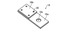
- the overlap portion 18 b of the conductive member 18 has a connection portion 30 in which the surfaces of the first conductive members facing each other with the clad material folded back are fixedly connected.
- the base portion 18a is provided with a through hole 18c through which the positive electrode terminal or the negative electrode terminal passes.
- connection part 30 which fixedly connected the surfaces of the opposing first conductive members
- the part where the bus bar is connected in the overlap part 18b and the negative terminal 16 are connected in the base part 18a. It is possible to reduce the resistance value between the two portions.
- connection part 30 can be formed by a method as shown in FIGS. 4 (a) and 4 (b), for example.
- FIGS. 4A and 4B show only a cross section of the overlap portion 18b.
- the overlap portion 18b is placed on the die 32 having the recess 32a formed on the surface, and the overlap portion 18b is pressed using the punch 31 from above.
- the connecting portion 30 is formed in the state where a part of the surface of the upper first conductive member 19a out of the first conductive member 19a overlapped with each other is driven into the lower first conductive member 19a.
- a concave portion is formed on the surface of the upper second conductive member 19b
- a convex portion is formed on the surface of the lower second conductive member 19b.
- the overlap portion 18b is pressed with a punch 31 from above using a die 32 having no recess formed on the surface.
- a concave portion is formed on the surface of the upper second conductive member 19b, but no convex portion is formed on the surface of the lower second conductive member 19b.
- connection part 30 illustrated in FIG. 3 was formed in the four corners of the overlap part 18b, it is not limited to this, You may form the connection part 30 by arbitrary positions and numbers.
- the connecting portion 30 is preferably provided at least in the vicinity of the boundary between the base portion 18a and the overlap portion 18b. With such a configuration, the resistance value between the portion where the bus bar is connected in the overlap portion 18b and the portion where the negative electrode terminal 16 is connected in the base portion 18a can be further reduced. In addition, it is possible to more reliably prevent the negative electrode conductive member from being deformed so that the opposing surfaces of the first conductive member 19a are separated from each other in the vicinity of the boundary between the base portion 18a and the overlap portion 18b.
- the folded portion of the plate-like member 19 is formed at the end of the negative electrode conductive member 18 in the longitudinal direction.
- a folded portion of the plate-like member 19 can be formed at one end portion in the width direction of the negative electrode conductive member 18.
- the width of the portion that becomes the overlap portion after folding may be made larger than the width of the portion that becomes the base portion.
- the negative electrode conductive member is produced by folding back one end portion of the clad material in which the first conductive member and the second conductive member are laminated.
- the negative electrode conductive member 18 may be produced by folding back one end of the plate member 19.
- the negative electrode conductive member 18 has an overlap portion 18b in which the opposed surfaces are overlapped with each other and a base portion 18a in which the surfaces are not overlapped with each other.
- the negative electrode terminal can be connected to the negative electrode conductive member 18 at the base portion 18a.
- the overlap part 18b can be made into the site
- the negative electrode conductive member 18 Since the negative electrode conductive member 18 having such a configuration is manufactured by folding back one end portion of the conductive plate member 19, the negative electrode conductive member 18 having portions having different thicknesses can be manufactured by a simpler method.
- the negative electrode conductive member 18 includes a thin base portion 18a and a thick overlap portion 18b. Therefore, in the negative electrode conductive member 18, the height of the surface to which the bus bar is connected (the upper surface of the overlap portion 18b) and the surface to which the negative electrode terminal 16 is connected (the upper surface of the base portion 18a) are not the same height.
- the bus bar is laser welded to the overlap portion 18b, it is possible to make a stronger weld connection with a higher energy laser without damaging the members arranged below the overlap portion 18b.
- the thickness of the base portion 18a is smaller than the thickness of the overlap portion 18b, the above-described effects can be obtained without increasing the height of the secondary battery in the vicinity of the connection portion between the negative electrode terminal 17 and the negative electrode conductive member 18.
- positioned under the overlap part 18b a sealing board, the insulating member arrange
- the positive electrode conductive member 17 may also be produced by folding back one end of a single conductive plate member.
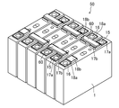
- FIG. 6 is a perspective view showing an example in which the assembled battery 50 is configured by arranging six secondary batteries 1 in the present invention.
- the positions of the positive electrode terminal 15 and the negative electrode terminal 16 of each secondary battery 1 are alternately switched and arranged, and the positive electrode terminal 15 and the negative electrode terminal 16 of the adjacent secondary battery 1 are connected to the bus bar 60.
- the six secondary batteries 1 are electrically connected in series.
- the positive electrode conductive member 17 and the negative electrode conductive member 18 are configured as follows. can do.
- the positive electrode conductive member 17 is folded at one end of a plate-like member 19 made of aluminum or an aluminum alloy, and the overlapped portion 18b in which the opposed surfaces are overlapped with each other.
- the negative electrode conductive member 18 has one end of a clad material 19 in which a first conductive member 19a made of copper or a copper alloy and a second conductive member 19b made of aluminum or an aluminum alloy are laminated.
- the first conductive member 19a is folded so that the surfaces of the first conductive member 19a overlap each other, and an overlapping portion 18b where the opposing surfaces overlap each other and a base portion 18a where the surfaces are not overlapped are used. be able to.
- the positive electrode terminal 15 is bonded to the base portion 17a of the positive electrode conductive member 17 by welding the same kind of metal (aluminum or aluminum alloy). Can do.
- the negative electrode terminal 16 can be joined to the base portion 18 a of the negative electrode conductive member 18 by welding the same kind of metal (copper or copper alloy).
- the overlap part 17b of the positive electrode conductive member 17 connected to the positive electrode terminal 15 of the adjacent secondary battery 1 and the overlap part 18b of the negative electrode conductive member 18 connected to the negative electrode terminal 16 are made of the same kind of metal ( It can be welded with a bus bar 60 made of aluminum or an aluminum alloy.
- both the positive electrode conductive member and the negative electrode conductive member do not have to be formed by folding one end of the plate-like member 19.
- a conductive member that is not folded back can be used as the positive electrode conductive member.
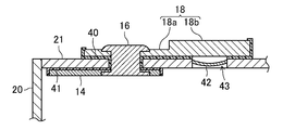
- an inversion plate (short-circuit mechanism) 42 may be provided in the vicinity of the negative electrode terminal 16.
- the negative electrode terminal 16 passes through a through-hole provided in the sealing body 21 and is fixed to the sealing body 21. Further, the negative electrode conductive member 18 disposed on the outer side of the sealing body 21 is connected to the negative electrode terminal 16 in the base portion 18a. The negative electrode terminal 16 is connected to the negative electrode current collector 14 on the inner side of the sealing body 21.
- the sealing body 21 is electrically insulated from the negative electrode terminal 16 and the negative electrode current collector 14 by insulating members 40 and 41.
- the positive electrode terminal (not shown) is electrically connected to the sealing body 21, and therefore the sealing body 21 has the same polarity as the positive electrode terminal.
- a hollow portion 43 is formed in a part of the sealing body 21, and an inversion plate 42 as a variable member is disposed so as to cover the hollow portion 43.
- the inversion plate 42 is electrically connected to the sealing body 21 and has the same polarity as the positive electrode terminal.
- the overlap portion 18 b of the negative electrode conductive member 18 extends to above the cavity portion 43.
- the reverse plate (short-circuit mechanism) 42 is provided in the vicinity of the negative electrode terminal 16, but may be provided in the vicinity of the positive electrode terminal.
- the positive terminal is electrically insulated from the sealing body, while the negative terminal is electrically connected to the sealing body 21.
- the reverse plate is preferably made of aluminum or an aluminum alloy. And it is preferable that the 2nd electrically-conductive member which comprises the surface which opposes a reverse plate in a negative electrode electrically-conductive member is also made from aluminum or aluminum alloy. Accordingly, when the reversing plate and the second conductive member come into contact with each other, the reversing plate and the second conductive member are melted and connected. Thereby, a short circuit current flows more reliably and the fuse part formed in the positive electrode current collector or the positive electrode conductive member can be surely blown.
- the first conductive member is preferably made of copper or a copper alloy. Thereby, even if the second conductive member in which the negative electrode conductive member is in contact with the reversal plate is melted, it is possible to reliably prevent an opening or the like from being formed in the negative electrode conductive member.
- the type of the secondary battery 1 in the present invention is not particularly limited, and can be applied to, for example, a lithium ion secondary battery, a nickel hydrogen secondary battery, or the like.
- the structure of the electrode body 10 is not particularly limited.
- a well-known material can be used about a positive electrode, a negative electrode, a separator, electrolyte solution, etc.
- Electrode body 11 Positive core exposed part 12 Negative core exposed part 13 Positive current collector 14 Negative electrode current collector 15 Positive terminal 16 Negative terminal 17 Positive Conductive Member 17a Base part 17b Overlap part 18 Negative electrode conductive member 18a Base part 18b Overlap part 18c through hole 19 Clad material (plate member) 19a First conductive member 19b Second conductive member 20 Exterior body 21 Sealing body 24 Sealing member 25 Discharge valve 30 connections 31 punch 32 die 32a recess 40, 41 Insulation member 42 Inversion plate (short-circuit mechanism) 43 Cavity 50 batteries 60 Busbar
Landscapes
- Chemical & Material Sciences (AREA)
- Chemical Kinetics & Catalysis (AREA)
- Electrochemistry (AREA)
- General Chemical & Material Sciences (AREA)
- Engineering & Computer Science (AREA)
- Manufacturing & Machinery (AREA)
- Connection Of Batteries Or Terminals (AREA)
- Sealing Battery Cases Or Jackets (AREA)
Abstract
正極端子又は負極端子に接続されるとともに、バスバーに接続される部位を有する導電部材を備えた二次電池において、簡単な構成で、かつ、正極端子又は負極端子、及びバスバーに対して信頼性の高い溶接が可能な導電部材を備えた二次電池を提供する。二次電池は、正極板及び負極板を備えた電極体(10)と、開口部を有し電極体を収納した外装体(20)と、開口部を封口する封口体(21)と、封口体に設けられ、正極板又は負極板に接続された端子(15)、(16)と、封口体の外部側に配置され、端子に接続された導電部材(17)、(18)とを備え、導電部材(18)は、導電性の板状部材の一端部が折り返されて、対向した面同士が重ね合わされたオーバラップ部と、面同士が重ね合わされていないベース部とを有し、端子は、ベース部において導電部材と接続されている。
Description
本発明は、正極端子又は負極端子に接続されるとともに、バスバーに接続される部位を有する導電部材を備えた二次電池及びその製造方法、並びに二次電池用導電部材の製造方法に関する。
複数の二次電池を電気的に直列に接続して構成した組電池は、並列された一方の二次電池の正極端子と、他方の二次電池の負極端子とが、バスバーで溶接されている。このとき、正極端子と負極端子とが異種金属で構成されている場合、単一種のバスバーを用いて、正負の端子に溶接すると、どちらか一方の端子で、異種金属どうしの溶接が生じる。しかしながら、異種金属どうしの溶接は、材料の組み合わせにより困難な場合がある。例えば、負極端子が銅で構成され、正極端子がアルミニウムで構成されている場合、アルミニウムで構成されたバスバーを負極端子に溶接すると、溶接部の信頼性が著しく低下する畏れがある。
このような問題に対して、特許文献1には、正極端子と同種の金属からなる金属板と、負極端子と同種の金属からなる金属板とが合わされた合板で構成されたバスバーが開示されている。この合板からなるバスバーを、長手方向の途中において、180°捻ることによって、あるいは、両端部を相反する方向に180°折り曲げることによって、同一平面内に2種類の金属板を配することができる。これにより、並列された二次電池の正極端子と負極端子とを、それぞれ、同種の金属からなる金属板で溶接することが可能となる。
しかしながら、特許文献1に開示されたバスバーは、並列される二次電池の間隔に応じて、合板の捻り加工や折り曲げ加工を行う必要がある。
本発明は、かかる点に鑑みなされたもので、その主な目的は、正極端子又は負極端子に接続されるとともに、バスバーに接続される部位を有する導電部材を備えた二次電池において、簡単な構成で、かつ、正極端子又は負極端子、及びバスバーに対して信頼性の高い溶接が可能な導電部材を備えた二次電池を提供することにある。
本発明に係る二次電池は、正極板及び負極板を備えた電極体と、開口部を有し電極体を収納した外装体と、開口部を封口する封口体と、封口体に設けられ、正極板又は負極板に接続された端子と、封口体の外部側に配置され、端子に接続された導電部材とを備え、導電部材は、導電性の板状部材の一端部が折り返されて、対向した面同士が重ね合わされたオーバラップ部と、面同士が重ね合わされていないベース部とを有し、端子は、ベース部において導電部材と接続されている。
ある好適な実施形態において、上記板状部材は、板状の第1導電部材と第2導電部材とが積層されたクラッド材からなり、第1導電部材は、上記端子と同種の金属からなり、オーバラップ部は、第1導電部材の面同士が重ね合わさるように折り返されており、導電部材は、ベース部において第1導電部材が表面に露出し、オーバラップ部において第2導電部材が表面に露出しており、端子は、ベース部において導電部材と接続されている。
本発明によれば、正極端子又は負極端子に接続されるとともに、バスバーに接続される部位を有する導電部材を備えた二次電池において、簡単な構成で、かつ、正極端子又は負極端子、及びバスバーに対して信頼性の高い溶接が可能な導電部材を備えた二次電池を提供することができる。
以下、本発明の実施形態を図面に基づいて詳細に説明する。なお、本発明は、以下の実施形態に限定されるものではない。また、本発明の効果を奏する範囲を逸脱しない範囲で、適宜変更は可能である。
図1は、本発明の一実施形態における二次電池1の構成を模式的に示した図で、図1(a)は上面図、図1(b)は断面図である。
図1(a)、(b)に示すように、本実施形態における二次電池1では、発電要素である電極体10が電解液とともに、外装体20に収納されている。また、外装体20の開口部は、封口体21で封口されている。ここで、電極体10は、正極板及び負極板がセパレータ(何れも不図示)を介して巻回、または積層された構造をなしている。正極板は、正極芯体表面に正極活物質を含む正極活物質層が設けられている。負極板は、負極芯体表面に負極活物質を含む負極活物質層が設けられている。また、正極板及び負極板は、それぞれ、その一側部において、活物質層が形成されていない正極芯体露出部11及び負極芯体露出部12を有している。そして、正極板及び負極板は、正極芯体露出部11及び負極芯体露出部12が、それぞれ反対方向に延出するように配置されている。
なお、正極端子15及び負極端子16は、封口板12の上面及び下面に設けられた絶縁部材(不図示)を介して、封口板12に固定されている。また、図1(a)、(b)には図示しないが、電極体13と外装体11との間には、箱状に折り曲げ加工された絶縁シートが配置されている。
正極芯体露出部11は、正極集電体13を介して、正極端子15に接続され、また、負極芯体露出部12は、負極集電体14を介して、負極端子16に接続されている。正極端子15及び負極端子16は、それぞれ、封口体21に設けられた貫通孔を貫通して封口体21に固定されている。さらに、封口体21の外部側において、正極端子15及び負極端子16には、それぞれ、正極導電部材17及び負極導電部材18が接続されている。また、正極導電部材17及び負極導電部材18は、それぞれ、正極端子15及び負極端子16に接続される部位となるベース部17a、18aと、バスバーに接続される部位となるオーバラップ部17b、18bとを有している。正極導電部材17のベース部17aに設けられた貫通孔に正極端子15が挿入され、正極端子15の上端がベース部17a上にカシメ固定されている。また、正極端子15のカシメられた部分がベース部17aと溶接されている。負極導電部材18のベース部18aに設けられた貫通孔に負極端子16が挿入され、負極端子16の上端がベース部18a上にカシメ固定されている。また、負極端子16のカシメられた部分がベース部18aと溶接されている。
負極端子16、負極導電部材18は、封口体21と電気的に絶縁されている。また、例えば、正極集電体13、正極端子15及び正極導電部材17の少なくとも一つが封口体21と接することにより、正極集電体13、正極端子15及び正極導電部材17が封口体21に電気的に接続されている。なお、正極集電体13、正極端子15及び正極導電部材17を封口体21と電気的に絶縁することもできる。
封口体21には、電解液を注液する注液孔が設けられ、この注液孔は、電解液を注液した後、封止部材24で封止される。また、封口体21には、外装体20の内部の圧力が上昇したときに破断し、圧力を開放する排出弁25が設けられている。
なお、二次電池1が非水電解質二次電池である場合、正極芯体、正極集電体13、及び正極端子15は、アルミニウムあるいはアルミニウム合金からなることが好ましい。また、負極芯体、負極集電体14、及び負極端子16は、銅あるいは銅合金であることが好ましい。なお、負極端子16の表面にニッケル層を設けることも可能性である。
外装体20及び封口体21は金属製であることが好ましく、アルミニウム、アルミニウム合金、ステンレス、鉄等からなることが好ましい。
図2(a)~(c)は、本実施形態における負極導電部材18を作製する工程を示した図である。
図2(a)に示すように、板状の第1導電部材19aと第2導電部材19bとが積層されたクラッド材19を用意する。ここで、第1導電部材19aは、負極端子16と同種の金属からなる。また、第2導電部材19bは、バスバーと同種の金属からなる。例えば、負極端子16が、銅あるいは銅合金からなる場合、第1導電部材19aは銅あるいは銅合金からなり、バスバーが、アルミニウムあるいはアルミニウム合金からなる場合、第2導電部材19bはアルミニウムあるいはアルミニウム合金からなる。
次に、図2(b)に示すように、クラッド材19の一端部を、第1導電部材19aの面同士が重ね合わさるように折り返す。これにより、図2(c)に示すように、第1導電部材19aの面同士が重ね合わされたオーバラップ部18bと、第1導電部材19aの面同士が重ね合わされていないベース部18aとを有する負極導電部材18が作製される。
図2(c)に示すように、本実施形態における負極導電部材18は、ベース部18aにおいて、第1導電部材19aが表面に露出し、オーバラップ部18bにおいて第2導電部材19bが表面に露出している。従って、図1(a)、(b)に示したように、封口体21の外部側に負極導電部材18を配置したとき、第1導電部材19aが表面に露出したベース部18aにおいて、負極端子16が接続され、第2導電部材19bが表面に露出したオーバラップ部18bにおいて、バスバーが接続される。なお、ベース部18aには、負極端子16が挿入される貫通孔が形成される。当該貫通孔の形成のタイミングは、クラッド材19の折り曲げ加工前、折り曲げ加工後のいずれであってもよい。
本実施形態において、第1導電部材19aは、負極端子16と同種の金属からなるため、同種の金属同士の溶接により、負極端子16と負極導電部材18とを接合することができる。また、第2導電部材19bは、バスバーと同種の金属からなるため、同種の金属同士の溶接により、バスバーと負極導電部材18とを接合することができる。これにより、負極端子16とバスバーとが異なる金属で構成されていても、負極端子16及びバスバーに対して、信頼性の高い溶接が可能な負極導電部材18を備えた二次電池を得ることができる。
なお、正極端子15が、バスバーと同種の金属(例えば、アルミニウムあるいはアルミニウム合金)からなる場合には、正極導電部材17を正極端子15と同種の金属で構成しておけばよい。これにより、正極端子15とバスバーとを、同種の金属同士の溶接により正極導電部材17に接合することができる。
一方、正極端子15が、バスバーと異種の金属からなる場合には、正極端子15と同種の金属からなる第1導電部材と、バスバーと同種の金属からなる第2導電部材とが積層されたクラッド材を、第1導電部材の面同士が重ね合わさるように折り返すことによって、正極導電部材17を作製すればよい。このとき、第1導電部材の面同士が重ね合わされていないベース部において、正極端子15と正極導電部材17とを、同種の金属同士の溶接により接合することができる。また、第1導電部材の面同士が重ね合わされたオーバラップ部において、バスバーと正極導電部材17とを、同種の金属同士の溶接により接合することができる。
本実施形態によれば、正極端子または負極端子に接続されるとともに、バスバーに接続される部位を有する導電部材を備えた二次電池において、第1導電部材と第2導電部材とが積層されたクラッド材を、第1導電部材の面同士が重ね合わさるように折り返して導電部材を作製することによって、第1導電部材の面同士が重ね合わされていないベース部において、正極端子又は負極端子と導電部材とを、同種の金属同士の溶接により接合することができる。また、第1導電部材の面同士が重ね合わされたオーバラップ部において、バスバーと導電部材とを、同種の金属同士の溶接により接合することができる。これにより、正極端子15または負極端子16とバスバーとが異なる金属で構成されていても、正極端子15または負極端子16及びバスバーに対して、信頼性の高い溶接が可能な導電部材を備えた二次電池を得ることができる。
なお、本実施形態において、導電部材を構成するクラッド材として、第1導電部材19aに、正極端子または負極端子と同種の金属を用い、第2導電部材19bに、バスバーと同種の金属を用いればよい。
また、本実施形態における導電部材は、第1導電部材と第2導電部材とが積層されたクラッド材の一端部を折り返すことによって作製されるため、低コストで、かつ強度の高い導電部材を得ることができる。
図3は、オーバラップ部における抵抗値の低減を図った導電部材の構成を模式的に示した斜視図である。
図3に示すように、導電部材18のオーバラップ部18bは、クラッド材が折り返されて対向した第1導電部材の面同士が固定接続された接続部30を有している。なお、ベース部18aには、正極端子または負極端子が貫通する貫通孔18cが設けられている。
このように、対向した第1導電部材の面同士を固定接続した接続部30が形成されていると、オーバラップ部18bにおいてバスバーが接続される部分と、ベース部18aにおいて負極端子16が接続される部分との間の抵抗値を低減することができる。
接続部30は、例えば、図4(a)、(b)に示すような方法で形成することができる。ここで、図4(a)、(b)は、オーバラップ部18bの断面のみ示している。
図4(a)に示した方法は、表面に凹部32aが形成されたダイ32の上にオーバラップ部18bを載置し、上方からパンチ31を用いてオーバラップ部18bをプレス加工する。これにより、対向して重ね合わされた第1導電部材19aのうち、上側の第1導電部材19aの面の一部が、下側の第1導電部材19aの内部に打ち込まれた状態で、接続部30が形成される。このとき、上側の第2導電部材19bの表面に凹部が形成されるとともに、下側の第2導電部材19bの表面に凸部が形成される。
図4(b)に示した方法は、表面に凹部が形成されていないダイ32を用いて、上方からパンチ31でオーバラップ部18bをプレス加工する。この場合には、上側の第2導電部材19bの表面に凹部が形成されるが、下側の第2導電部材19bの表面に凸部は形成されない。
なお、図3に例示した接続部30は、オーバラップ部18bの四隅に形成したが、これに限定されず、任意の位置及び個数で接続部30を形成してもよい。なお、接続部30は、少なくとも、ベース部18aとオーバラップ部18bとの境界近傍の位置に設けることが好ましい。このような構成であれば、オーバラップ部18bにおいてバスバーが接続される部分とベース部18aにおいて負極端子16が接続される部分との間の抵抗値をより低減することができる。また、ベース部18aとオーバラップ部18bとの境界近傍において、対抗する第1導電部材19aの面同士が離れるように負極導電部材が変形することをより確実に防止できる。
図3に示す負極導電部材18では、板状部材19の折り返し部が負極導電部材18の長手方向における端部に形成される。他の実施形態として、負極導電部材18の幅方向における一方の端部に、板状部材19の折り返し部が形成されるようにすることができる。この場合は、板状部材19において、折り返し後 オーバラップ部となる部分の幅を、ベース部となる部分の幅よりも大きくしておけばよい。
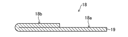
以上、本発明を好適な実施形態により説明してきたが、こうした記述は限定事項ではなく、もちろん、種々の改変が可能である。例えば、上記実施形態では、負極導電部材を、第1導電部材と第2導電部材とが積層されたクラッド材の一端部を折り返して作製したが、図5に示すように、単一の導電性の板状部材19の一端部を折り返して負極導電部材18を作製してもよい。この場合、負極導電部材18は、対向した面同士が重ね合わされたオーバラップ部18bと、面同士が重ね合わされていないベース部18aとを有する。そして、負極端子は、ベース部18aにおいて、負極導電部材18と接続することができる。また、オーバラップ部18bを、バスバーを接合する部位とすることができる。
このような構成の負極導電部材18は、導電性の板状部材19の一端部を折り返すことによって作製されるため、より簡単な方法で、厚みの異なる部分を有する負極導電部材18が作製できる。負極導電部材18は、厚みの薄いベース部18aと、厚みの厚いオーバラップ部18bとを有する。したがって、負極導電部材18において、バスバーが接続される面(オーバラップ部18bの上面)と、負極端子16が接続される面(ベース部18aの上面)の高さが同一の高さとならない。このため、負極導電部材18のオーバラップ部18bにバスバーを接続する際、バスバーや治具等が負極導電部材18のベース部18aと負極端子16の接続部に接触し当該接続部を損傷させることをより確実に防止できる。
また、オーバラップ部18bにバスバーをレーザ溶接する場合、オーバラップ部18bの下方に配置された部材を損傷させることなく、より高エネルギーのレーザでより強固に溶接接続することが可能である。ここで、ベース部18aの厚みはオーバラップ部18bの厚みより小さいため、負極端子17と負極導電部材18の接続部近傍の二次電池の高さを高くすることなく、上述の効果が得られる。なお、オーバラップ部18bの下方に配置された部材としては、封口板、負極導電部材18と封口板の間に配置される絶縁部材、あるいは後述する反転プレート等が挙げられる。
なお、正極導電部材17も、単一の導電性の板状部材の一端部を折り返して作製してもよい。
本発明における二次電池1を、複数個配列して組電池を構成することもできる。図6は、本発明における二次電池1を6個配列して、組電池50を構成した例を示した斜視図である。
図6に示すように、各二次電池1の正極端子15及び負極端子16の位置を、交互に入れ替えて配列し、隣り合う二次電池1の正極端子15と負極端子16とを、バスバー60で接合することによって、6個の二次電池1が電気的に直列に接続されている。例えば、正極端子15及びバスバー60が、アルミニウムあるいはアルミニウム合金からなり、負極端子16が、銅あるいは銅合金からなる場合、正極導電部材17及び負極導電部材18は、以下のような構成のものを使用することができる。
すなわち、正極導電部材17は、図5に示したように、アルミニウムあるいはアルミニウム合金からなる板状部材19の一端部を折り返し、対向した面同士が重ね合わされたオーバラップ部18bと、面同士が重ね合わされていないベース部18aとを有する構成のものを用いることができる。また、負極導電部材18は、図2に示したように、銅あるいは銅合金からなる第1導電部材19aと、アルミニウムあるいはアルミニウム合金からなる第2導電部材19bとが積層されたクラッド材19の一端部を、第1導電部材19aの面同士が重ね合わさるように折り返し、対向した面同士が重ね合わされたオーバラップ部18bと、面同士が重ね合わされていないベース部18aとを有する構成のものを用いることができる。
このような構成の正極導電部材17及び負極導電部材18を用いることにより、正極端子15は、正極導電部材17のベース部17aにおいて、同種の金属(アルミニウムあるいはアルミニウム合金)同士の溶接により接合することができる。また、負極端子16は、負極導電部材18のベース部18aにおいて、同種の金属(銅あるいは銅合金)同士の溶接により接合することができる。さらに、隣り合う二次電池1の正極端子15に接続された正極導電部材17のオーバラップ部17bと、負極端子16に接続された負極導電部材18のオーバラップ部18bとを、同種の金属(アルミニウムあるいはアルミニウム合金)からなるバスバー60で溶接することができる。その結果、二次電池1の正極端子15及び負極端子16が異なる金属で構成されていても、正極端子15、負極端子16及びバスバー60に対して、信頼性の高い溶接で接合された組電池50を得ることができる。なお、正極導電部材と負極導電部材の両方が、板状部材19の一端部が折り返されたものである必要はない。例えば、正極導電部材として、折り返し加工されていない導電部材を用いることも可能である。
また、本発明における二次電池において、図7に示すように、負極端子16の近傍に、反転プレート(短絡機構)42を設けてもよい。
図7に示すように、負極端子16は、封口体21に設けられた貫通孔を貫通して封口体21に固定されている。また、封口体21の外部側に配置された負極導電部材18は、ベース部18aにおいて、負極端子16に接続されている。また、負極端子16は、封口体21の内部側において、負極集電体14に接続されている。なお、封口体21は、絶縁部材40、41により負極端子16及び負極集電体14と電気的に絶縁されている。一方、正極端子(不図示)は、封口体21と電気的に接続されており、そのため、封口体21は、正極端子と同一の極性を有している。
封口体21の一部には、空洞部43が形成され、この空洞部43を覆うように可変部材としての反転プレート42が配置されている。ここで、反転プレート42は、封口体21と電気的に接続されており、正極端子と同一の極性を有している。また、負極導電部材18のオーバラップ部18bは、空洞部43の上方まで延出している。そして、二次電池が過充電状態になって、外装体20の内部の圧力が設定値以上になったとき、反転プレート42は反転して、負極導電部材18のオーバラップ部18bと接触する。これにより、反転プレート42は、正極板と負極板とを電極体の外部で電気的に短絡させる短絡機構として作用する。
なお、図7では、反転プレート(短絡機構)42を負極端子16の近傍に設けたが、正極端子の近傍に設けてもよい。この場合、正極端子は、封口体と電気的に絶縁されている一方、負極端子は、封口体21と電気的に接続されている。
反転プレートはアルミニウム又はアルミニウム合金製であることが好ましい。そして、負極導電部材において反転プレートと対向する面を構成する第2導電部材も、アルミニウム又はアルミニウム合金製であることが好ましい。これにより、反転プレートと第2導電部材が接触したときに、反転プレートと第2導電部材が溶融し接続される。これにより、より確実に短絡電流が流れ、正極集電体ないし正極導電部材に形成されたヒューズ部を確実に溶断させることができる。また、第1導電部材が銅又は銅合金製からなることが好ましい。これにより、負極導電部材が反転プレートと接触した第2導電部材が溶融したとしても、負極導電部材に開口等が形成されることを確実に防止できる。
本発明における二次電池1は、その種類は、特に限定されず、例えば、リチウムイオン二次電池、ニッケル水素二次電池等に適用することができる。また、電極体10も、その構造は特に限定されない。また、正極、負極、セパレータ、電解液等については公知の材料を使用できる。
1 二次電池
10 電極体
11 正極芯体露出部
12 負極芯体露出部
13 正極集電体
14 負極集電体
15 正極端子
16 負極端子
17 正極導電部材
17a ベース部
17b オーバラップ部
18 負極導電部材
18a ベース部
18b オーバラップ部
18c 貫通孔
19 クラッド材(板状部材)
19a 第1導電部材
19b 第2導電部材
20 外装体
21 封口体
24 封止部材
25 排出弁
30 接続部
31 パンチ
32 ダイ
32a 凹部
40、41 絶縁部材
42 反転プレート(短絡機構)
43 空洞部
50 組電池
60 バスバー
10 電極体
11 正極芯体露出部
12 負極芯体露出部
13 正極集電体
14 負極集電体
15 正極端子
16 負極端子
17 正極導電部材
17a ベース部
17b オーバラップ部
18 負極導電部材
18a ベース部
18b オーバラップ部
18c 貫通孔
19 クラッド材(板状部材)
19a 第1導電部材
19b 第2導電部材
20 外装体
21 封口体
24 封止部材
25 排出弁
30 接続部
31 パンチ
32 ダイ
32a 凹部
40、41 絶縁部材
42 反転プレート(短絡機構)
43 空洞部
50 組電池
60 バスバー
Claims (10)
- 正極板及び負極板を備えた電極体と、
開口部を有し、前記電極体を収納した外装体と、
前記開口部を封口する封口体と、
前記封口体に設けられ、前記正極板又は前記負極板に接続された端子と、
前記封口体の外部側に配置され、前記端子に接続された導電部材と
を備えた二次電池であって、
前記導電部材は、導電性の板状部材の一端部が折り返されて、対向した面同士が重ね合わされたオーバラップ部と、面同士が重ね合わされていないベース部とを有し、
前記端子は、前記ベース部において、前記導電部材と接続されている、二次電池。 - 前記板状部材は、板状の第1導電部材と第2導電部材とが積層されたクラッド材からなり、
前記第1導電部材は、前記端子と同種の金属からなり、
前記オーバラップ部は、前記第1導電部材の面同士が重ね合わさるように折り返されており、
前記導電部材は、前記ベース部において前記第1導電部材が表面に露出し、前記オーバラップ部において前記第2導電部材が表面に露出しており、
前記端子は、前記ベース部において、前記第1導電部材と接続されている、請求項1に記載の二次電池。 - 前記第2導電部材は、バスバーと同種の金属からなり、
前記オーバラップ部は、バスバーを接合する部位となる、請求項2に記載の二次電池。 - 前記オーバラップ部は、折り返されて対向した面同士が固定接続された接続部を有する、請求項1~3の何れかに記載の二次電池。
- 前記接続部は、折り返されて対向した面同士が圧着接続されている、請求項4に記載の二次電池。
- 前記第1導電部材は、銅又は銅合金からなり、前記第2導電部材は、アルミニウム又はアルミニウム合金からなる、請求項2または3に記載の二次電池。
- 正極板及び負極板を備えた電極体と、
開口部を有し、前記電極体を収納した外装体と、
前記開口部を封口する封口体と、
前記封口体に設けられ、前記正極板又は前記負極板に接続された端子と、
を備えた二次電池の製造方法であって、
導電性の板材部材の一端部を折り返すことによって、折り返されて対向した面同士が重ね合わされたオーバラップ部と、面同士が重ならないベース部と、を有する導電部材を前記封口体に配置して、前記端子を前記導電部材に接続する工程
を含み、
前記端子は、前記ベース部において、前記導電部材と接続される、二次電池の製造方法。 - 前記板材部材は、板状の第1導電部材と第2導電部材とが積層されたクラッド材からなり、
前記第1導電部材は、前記端子と同種の金属からなり、
前記オーバラップ部は、前記第1導電部材の面同士が重ね合わさるように折り返されて形成される、請求項7に記載の二次電池の製造方法。 - 請求項1に記載の二次電池を構成する導電部材の製造方法であって、
前記導電部材は、導電性の板状部材からなり、
前記板状部材の一端部を折り返すことによって、折り返されて対向した面同士が重ね合わされたオーバラップ部と、面同士が重ならないベース部とを有する導電部材が形成される、二次電池用導電部材の製造方法。 - 前記板状部材は、板状の第1導電部材と第2導電部材とが積層されたクラッド材からなり、
前記第1導電部材は、前記端子と同種の金属からなり、
前記オーバラップ部は、前記第1導電部材の面同士が重ね合わさるように折り返されて形成される、請求項9に記載の二次電池用導電部材の製造方法。
Priority Applications (3)
| Application Number | Priority Date | Filing Date | Title |
|---|---|---|---|
| JP2018540286A JP6971990B2 (ja) | 2016-09-26 | 2017-09-21 | 二次電池、二次電池の製造方法、及び二次電池用導電部材の製造方法 |
| US16/334,470 US11342618B2 (en) | 2016-09-26 | 2017-09-21 | Secondary battery, method of manufacturing the same, and method of manufacturing conductive member for the same |
| CN201780058944.6A CN109792030B (zh) | 2016-09-26 | 2017-09-21 | 二次电池、二次电池的制造方法及二次电池用导电构件的制造方法 |
Applications Claiming Priority (2)
| Application Number | Priority Date | Filing Date | Title |
|---|---|---|---|
| JP2016186841 | 2016-09-26 | ||
| JP2016-186841 | 2016-09-26 |
Publications (1)
| Publication Number | Publication Date |
|---|---|
| WO2018056345A1 true WO2018056345A1 (ja) | 2018-03-29 |
Family
ID=61689608
Family Applications (1)
| Application Number | Title | Priority Date | Filing Date |
|---|---|---|---|
| PCT/JP2017/034036 Ceased WO2018056345A1 (ja) | 2016-09-26 | 2017-09-21 | 二次電池、二次電池の製造方法、及び二次電池用導電部材の製造方法 |
Country Status (4)
| Country | Link |
|---|---|
| US (1) | US11342618B2 (ja) |
| JP (1) | JP6971990B2 (ja) |
| CN (1) | CN109792030B (ja) |
| WO (1) | WO2018056345A1 (ja) |
Cited By (1)
| Publication number | Priority date | Publication date | Assignee | Title |
|---|---|---|---|---|
| JP2023027989A (ja) * | 2021-08-18 | 2023-03-03 | トヨタ自動車株式会社 | 組電池およびその製造方法 |
Families Citing this family (1)
| Publication number | Priority date | Publication date | Assignee | Title |
|---|---|---|---|---|
| CN115053393B (zh) * | 2020-03-31 | 2024-10-01 | 松下知识产权经营株式会社 | 蓄电模块 |
Citations (4)
| Publication number | Priority date | Publication date | Assignee | Title |
|---|---|---|---|---|
| JP2008311074A (ja) * | 2007-06-14 | 2008-12-25 | Nec Tokin Corp | タブ端子 |
| JP2010186705A (ja) * | 2009-02-13 | 2010-08-26 | Hitachi Maxell Ltd | 電池 |
| JP2012123946A (ja) * | 2010-12-06 | 2012-06-28 | Hitachi Vehicle Energy Ltd | 二次電池 |
| WO2014178130A1 (ja) * | 2013-05-01 | 2014-11-06 | 日立オートモティブシステムズ株式会社 | 角形電池及び組電池 |
Family Cites Families (12)
| Publication number | Priority date | Publication date | Assignee | Title |
|---|---|---|---|---|
| US6844110B2 (en) | 2000-05-24 | 2005-01-18 | Ngk Insulators, Ltd. | Lithium secondary cell and assembly thereof |
| JP2002151045A (ja) | 2000-11-10 | 2002-05-24 | Honda Motor Co Ltd | 電池モジュール用バスバーおよび電池モジュール |
| JP2002358945A (ja) | 2000-11-15 | 2002-12-13 | Ngk Insulators Ltd | リチウム二次単電池の接続構造体 |
| CN102386369B (zh) * | 2007-01-12 | 2015-09-30 | 丰田自动车株式会社 | 电极 |
| DE102010005021A1 (de) * | 2010-01-19 | 2011-07-21 | Continental Automotive GmbH, 30165 | Flachleitervorrichtung und elektrischer Energiespeicher |
| JP5840207B2 (ja) * | 2011-06-10 | 2016-01-06 | 日立オートモティブシステムズ株式会社 | 二次電池 |
| WO2013065523A1 (ja) | 2011-10-31 | 2013-05-10 | 三洋電機株式会社 | 組電池及びこの組電池に使用するための角形二次電池 |
| JP5637181B2 (ja) * | 2012-06-29 | 2014-12-10 | トヨタ自動車株式会社 | 電池、電池の製造方法、及び、電池製造用マスク部材 |
| JP5803875B2 (ja) * | 2012-10-19 | 2015-11-04 | トヨタ自動車株式会社 | 密閉型電池 |
| JP6462233B2 (ja) * | 2014-05-07 | 2019-01-30 | 古河電気工業株式会社 | 電流検出構造 |
| KR102356939B1 (ko) * | 2015-04-27 | 2022-01-28 | 삼성에스디아이 주식회사 | 배터리 모듈 |
| CN204946952U (zh) * | 2015-09-21 | 2016-01-06 | 宁德时代新能源科技有限公司 | 二次电池顶盖及二次电池 |
-
2017
- 2017-09-21 US US16/334,470 patent/US11342618B2/en active Active
- 2017-09-21 JP JP2018540286A patent/JP6971990B2/ja active Active
- 2017-09-21 WO PCT/JP2017/034036 patent/WO2018056345A1/ja not_active Ceased
- 2017-09-21 CN CN201780058944.6A patent/CN109792030B/zh active Active
Patent Citations (4)
| Publication number | Priority date | Publication date | Assignee | Title |
|---|---|---|---|---|
| JP2008311074A (ja) * | 2007-06-14 | 2008-12-25 | Nec Tokin Corp | タブ端子 |
| JP2010186705A (ja) * | 2009-02-13 | 2010-08-26 | Hitachi Maxell Ltd | 電池 |
| JP2012123946A (ja) * | 2010-12-06 | 2012-06-28 | Hitachi Vehicle Energy Ltd | 二次電池 |
| WO2014178130A1 (ja) * | 2013-05-01 | 2014-11-06 | 日立オートモティブシステムズ株式会社 | 角形電池及び組電池 |
Cited By (2)
| Publication number | Priority date | Publication date | Assignee | Title |
|---|---|---|---|---|
| JP2023027989A (ja) * | 2021-08-18 | 2023-03-03 | トヨタ自動車株式会社 | 組電池およびその製造方法 |
| JP7658850B2 (ja) | 2021-08-18 | 2025-04-08 | トヨタ自動車株式会社 | 組電池およびその製造方法 |
Also Published As
| Publication number | Publication date |
|---|---|
| JP6971990B2 (ja) | 2021-11-24 |
| JPWO2018056345A1 (ja) | 2019-07-04 |
| US20210305647A1 (en) | 2021-09-30 |
| US11342618B2 (en) | 2022-05-24 |
| CN109792030A (zh) | 2019-05-21 |
| CN109792030B (zh) | 2021-07-06 |
Similar Documents
| Publication | Publication Date | Title |
|---|---|---|
| US20250192345A1 (en) | Secondary battery | |
| KR101858482B1 (ko) | 집전 부재를 구비하는 축전 소자 및 집전 부재의 제조 방법 | |
| JP5856858B2 (ja) | 角形二次電池の製造方法 | |
| KR101818631B1 (ko) | 전지 및 그 제조 방법 | |
| KR100590006B1 (ko) | 이차 전지와 이에 사용되는 전극 조립체 | |
| JP5157027B2 (ja) | 電池 | |
| KR100846074B1 (ko) | 파우치형 전지의 입체형 전극단자 | |
| KR20180041019A (ko) | 용접성이 향상된 돌기부가 형성되어 있는 원통형 이차전지 | |
| US12266807B2 (en) | Rectangular secondary cell and method for manufacturing same | |
| JP6971990B2 (ja) | 二次電池、二次電池の製造方法、及び二次電池用導電部材の製造方法 | |
| JP7028825B2 (ja) | 組電池 | |
| JP2019067580A (ja) | 蓄電素子 | |
| JP5440663B2 (ja) | 電池 | |
| KR20190016239A (ko) | 배터리 모듈 | |
| JP2019175687A (ja) | 蓄電装置 | |
| JP7767576B2 (ja) | 電池及び電池の製造方法 | |
| JP2015056341A (ja) | 蓄電モジュール | |
| JP5582243B2 (ja) | 電池 | |
| JP2013214536A (ja) | 電池 | |
| JP2014029886A (ja) | 電池の製造方法 | |
| JP2014053325A (ja) | 電池 |
Legal Events
| Date | Code | Title | Description |
|---|---|---|---|
| 121 | Ep: the epo has been informed by wipo that ep was designated in this application |
Ref document number: 17853114 Country of ref document: EP Kind code of ref document: A1 |
|
| ENP | Entry into the national phase |
Ref document number: 2018540286 Country of ref document: JP Kind code of ref document: A |
|
| NENP | Non-entry into the national phase |
Ref country code: DE |
|
| 122 | Ep: pct application non-entry in european phase |
Ref document number: 17853114 Country of ref document: EP Kind code of ref document: A1 |