WO2018056338A1 - ユーザ端末及び無線通信方法 - Google Patents
ユーザ端末及び無線通信方法 Download PDFInfo
- Publication number
- WO2018056338A1 WO2018056338A1 PCT/JP2017/034014 JP2017034014W WO2018056338A1 WO 2018056338 A1 WO2018056338 A1 WO 2018056338A1 JP 2017034014 W JP2017034014 W JP 2017034014W WO 2018056338 A1 WO2018056338 A1 WO 2018056338A1
- Authority
- WO
- WIPO (PCT)
- Prior art keywords
- transmission
- user terminal
- information
- timing
- data
- Prior art date
Links
Images


Classifications
-
- H—ELECTRICITY
- H04—ELECTRIC COMMUNICATION TECHNIQUE
- H04L—TRANSMISSION OF DIGITAL INFORMATION, e.g. TELEGRAPHIC COMMUNICATION
- H04L1/00—Arrangements for detecting or preventing errors in the information received
- H04L1/12—Arrangements for detecting or preventing errors in the information received by using return channel
- H04L1/16—Arrangements for detecting or preventing errors in the information received by using return channel in which the return channel carries supervisory signals, e.g. repetition request signals
- H04L1/18—Automatic repetition systems, e.g. Van Duuren systems
- H04L1/1829—Arrangements specially adapted for the receiver end
- H04L1/1854—Scheduling and prioritising arrangements
-
- H—ELECTRICITY
- H04—ELECTRIC COMMUNICATION TECHNIQUE
- H04W—WIRELESS COMMUNICATION NETWORKS
- H04W52/00—Power management, e.g. TPC [Transmission Power Control], power saving or power classes
- H04W52/04—TPC
- H04W52/38—TPC being performed in particular situations
- H04W52/48—TPC being performed in particular situations during retransmission after error or non-acknowledgment
-
- H—ELECTRICITY
- H04—ELECTRIC COMMUNICATION TECHNIQUE
- H04L—TRANSMISSION OF DIGITAL INFORMATION, e.g. TELEGRAPHIC COMMUNICATION
- H04L1/00—Arrangements for detecting or preventing errors in the information received
- H04L1/12—Arrangements for detecting or preventing errors in the information received by using return channel
- H04L1/16—Arrangements for detecting or preventing errors in the information received by using return channel in which the return channel carries supervisory signals, e.g. repetition request signals
- H04L1/18—Automatic repetition systems, e.g. Van Duuren systems
- H04L1/1829—Arrangements specially adapted for the receiver end
- H04L1/1861—Physical mapping arrangements
-
- H—ELECTRICITY
- H04—ELECTRIC COMMUNICATION TECHNIQUE
- H04L—TRANSMISSION OF DIGITAL INFORMATION, e.g. TELEGRAPHIC COMMUNICATION
- H04L1/00—Arrangements for detecting or preventing errors in the information received
- H04L1/12—Arrangements for detecting or preventing errors in the information received by using return channel
- H04L1/16—Arrangements for detecting or preventing errors in the information received by using return channel in which the return channel carries supervisory signals, e.g. repetition request signals
- H04L1/18—Automatic repetition systems, e.g. Van Duuren systems
- H04L1/1867—Arrangements specially adapted for the transmitter end
- H04L1/1896—ARQ related signaling
-
- H—ELECTRICITY
- H04—ELECTRIC COMMUNICATION TECHNIQUE
- H04L—TRANSMISSION OF DIGITAL INFORMATION, e.g. TELEGRAPHIC COMMUNICATION
- H04L5/00—Arrangements affording multiple use of the transmission path
- H04L5/003—Arrangements for allocating sub-channels of the transmission path
- H04L5/0053—Allocation of signaling, i.e. of overhead other than pilot signals
- H04L5/0055—Physical resource allocation for ACK/NACK
-
- H—ELECTRICITY
- H04—ELECTRIC COMMUNICATION TECHNIQUE
- H04L—TRANSMISSION OF DIGITAL INFORMATION, e.g. TELEGRAPHIC COMMUNICATION
- H04L5/00—Arrangements affording multiple use of the transmission path
- H04L5/003—Arrangements for allocating sub-channels of the transmission path
- H04L5/0078—Timing of allocation
- H04L5/0082—Timing of allocation at predetermined intervals
-
- H—ELECTRICITY
- H04—ELECTRIC COMMUNICATION TECHNIQUE
- H04W—WIRELESS COMMUNICATION NETWORKS
- H04W28/00—Network traffic management; Network resource management
- H04W28/02—Traffic management, e.g. flow control or congestion control
- H04W28/04—Error control
-
- H—ELECTRICITY
- H04—ELECTRIC COMMUNICATION TECHNIQUE
- H04W—WIRELESS COMMUNICATION NETWORKS
- H04W52/00—Power management, e.g. TPC [Transmission Power Control], power saving or power classes
- H04W52/04—TPC
- H04W52/06—TPC algorithms
- H04W52/14—Separate analysis of uplink or downlink
- H04W52/143—Downlink power control
-
- H—ELECTRICITY
- H04—ELECTRIC COMMUNICATION TECHNIQUE
- H04W—WIRELESS COMMUNICATION NETWORKS
- H04W72/00—Local resource management
- H04W72/04—Wireless resource allocation
-
- H—ELECTRICITY
- H04—ELECTRIC COMMUNICATION TECHNIQUE
- H04W—WIRELESS COMMUNICATION NETWORKS
- H04W72/00—Local resource management
- H04W72/12—Wireless traffic scheduling
-
- H—ELECTRICITY
- H04—ELECTRIC COMMUNICATION TECHNIQUE
- H04W—WIRELESS COMMUNICATION NETWORKS
- H04W72/00—Local resource management
- H04W72/20—Control channels or signalling for resource management
- H04W72/23—Control channels or signalling for resource management in the downlink direction of a wireless link, i.e. towards a terminal
-
- H—ELECTRICITY
- H04—ELECTRIC COMMUNICATION TECHNIQUE
- H04W—WIRELESS COMMUNICATION NETWORKS
- H04W80/00—Wireless network protocols or protocol adaptations to wireless operation
- H04W80/08—Upper layer protocols
-
- H—ELECTRICITY
- H04—ELECTRIC COMMUNICATION TECHNIQUE
- H04L—TRANSMISSION OF DIGITAL INFORMATION, e.g. TELEGRAPHIC COMMUNICATION
- H04L5/00—Arrangements affording multiple use of the transmission path
- H04L5/0091—Signaling for the administration of the divided path
- H04L5/0094—Indication of how sub-channels of the path are allocated
-
- Y—GENERAL TAGGING OF NEW TECHNOLOGICAL DEVELOPMENTS; GENERAL TAGGING OF CROSS-SECTIONAL TECHNOLOGIES SPANNING OVER SEVERAL SECTIONS OF THE IPC; TECHNICAL SUBJECTS COVERED BY FORMER USPC CROSS-REFERENCE ART COLLECTIONS [XRACs] AND DIGESTS
- Y02—TECHNOLOGIES OR APPLICATIONS FOR MITIGATION OR ADAPTATION AGAINST CLIMATE CHANGE
- Y02D—CLIMATE CHANGE MITIGATION TECHNOLOGIES IN INFORMATION AND COMMUNICATION TECHNOLOGIES [ICT], I.E. INFORMATION AND COMMUNICATION TECHNOLOGIES AIMING AT THE REDUCTION OF THEIR OWN ENERGY USE
- Y02D30/00—Reducing energy consumption in communication networks
- Y02D30/70—Reducing energy consumption in communication networks in wireless communication networks
Definitions
- the present invention relates to a user terminal and a wireless communication method in a next generation mobile communication system.
- LTE Long Term Evolution
- Non-Patent Document 1 LTE-A (LTE-Advanced), FRA (Future Radio Access), 4G, 5G, 5G + (plus), NR ( New RAT) and LTE Rel.14, 15 ⁇ ) are also being considered.
- TTI Transmission Time Interval
- DL Downlink
- UL Uplink
- the 1 ms TTI is a transmission time unit of one channel-coded data packet, and is a processing unit such as scheduling, link adaptation, retransmission control (HARQ: Hybrid Automatic Repeat reQuest).
- HARQ Hybrid Automatic Repeat reQuest
- the existing LTE system (for example, LTE Rel. 8-13) supports frequency division duplex (FDD) and time division duplex (TDD) as duplex schemes.
- FDD is a method of assigning different frequencies between DL and UL, and is called a frame structure (FS) type 1 or the like.
- TDD is a method of switching the same frequency in time between DL and UL, and is called frame structure type 2 or the like.
- communication is performed based on a UL / DL configuration (UL / DL configuration) that defines a configuration of a UL subframe and a DL subframe in a radio frame.
- the transmission timing reference value is fixed to 4 ms in consideration of the signal processing time in the user terminal and / or the radio base station.
- retransmission control information for example, ACK (Acknowledge) or NACK (Negative ACK), A / N, HARQ-ACK, etc. for a DL shared channel (for example, PDSCH: Physical Downlink Shared Channel), hereinafter referred to as PDSCH)
- PDSCH Physical Downlink Shared Channel
- the PDSCH processing time in the user terminal is assumed to be 4 ms, and the PDSCH A / N is transmitted (feedback) in subframe # n + 4.
- the PDSCH processing time in the user terminal is assumed to be 4 ms, and the A / N of the PDSCH is determined according to the UL / DL configuration or the like. It is transmitted in UL subframes after frame # n + 4.
- a / N transmission timing (UL HARQ timing, etc.) for a UL shared channel for example, PUSCH: Physical Uplink Shared Channel, hereinafter referred to as PUSCH.
- PUSCH Physical Uplink Shared Channel
- E-UTRA Evolved Universal Terrestrial Radio Access
- E-UTRAN Evolved Universal Terrestrial Radio Access Network
- the wireless frame (also referred to as Lean radio frame) is highly scalable in the future and has excellent power consumption. ) Is being considered.
- a radio frame does not use a predetermined UL / DL configuration as in the existing LTE system, but has a configuration in which the transmission direction of UL or DL can be dynamically changed (also called Highly flexible dynamic TDD). Say).
- transmission / reception timing of signals in an existing LTE system for example, LTE Rel. 8-13
- transmission timing of UL signals for DL transmission such as A / N
- UL transmission is appropriately controlled. It may not be possible.
- the present invention has been made in view of this point, and an object of the present invention is to provide a user terminal and a wireless communication method capable of appropriately controlling transmission of a UL signal for DL transmission in a future wireless communication system. .
- One aspect of the user terminal of the present invention includes a receiving unit that receives downlink control information and downlink data, and a control unit that controls transmission of an acknowledgment signal for the downlink data, and the control unit includes the downlink control information.
- the transmission timing of the delivery confirmation signal is controlled based on timing information included in the control information.
- 1A to 1G are diagrams illustrating an example of a frame configuration that can be used in the present embodiment. It is a figure which shows an example of A / N transmission control corresponding to DL data. It is a figure which shows the other example of A / N transmission control corresponding to DL data. It is a figure which shows the other example of A / N transmission control corresponding to DL data. 5A and 5B are diagrams illustrating another example of A / N transmission control corresponding to DL data. 6A and 6B are diagrams illustrating another example of A / N transmission control corresponding to DL data.
- FIG. 7 is a diagram illustrating another example of A / N transmission control corresponding to DL data.
- Is a diagram showing a table M, k m is defined to be applied by the PUCCH transmission. It is a figure explaining transmission power control in A / N transmission corresponding to DL data. It is a figure which shows an example of schematic structure of the radio
- HARQ Hybrid Automatic Repeat reQuest
- the user terminal In the DL of the existing LTE system, the user terminal is also referred to as a delivery confirmation signal (retransmission control signal, HARQ-ACK, ACK / NACK, A / N) of the PDSCH based on the reception result of the DL signal (for example, PDSCH). ).
- the user terminal can transmit A / N using an uplink control channel (for example, PUCCH) and / or an uplink shared channel (for example, PUSCH).
- the radio base station controls PDSCH transmission (including initial transmission and / or retransmission) based on the A / N from the user terminal.
- a user terminal transmits the uplink data (for example, PUSCH) scheduled by UL grant transmitted from a radio base station.
- a / N transmission, UL data transmission, and the like are controlled after a predetermined time from a subframe in which a DL signal is transmitted and received based on a predefined transmission timing. For example, in FDD, a user terminal transmits A / N of the PDSCH in a subframe 4 ms after the subframe that received the PDSCH. Further, the user terminal transmits a PUSCH corresponding to the UL grant in a subframe 4 ms after the subframe in which the UL grant is received.
- the processing time in the existing LTE system may be referred to as normal processing time.
- a processing time shorter than the normal processing time may be referred to as a shortened processing time.
- the user terminal for which the shortening processing time is set controls transmission / reception processing (encoding, etc.) of the signal so as to transmit / receive a predetermined signal at a timing earlier than the transmission / reception timing defined in the existing LTE system.
- the shortening process time may be set for a specific process (may be set for each signal or for each process), or may be set for all processes.
- the user terminal can use an existing channel (PDCCH, PDSCH, PUSCH, PUCCH, etc.). ) To control the processing timing of the predetermined operation earlier than the existing system.
- the user terminal to which the shortening processing time is set is assumed that the following time in the existing LTE system is shorter than a predetermined time (for example, 4 ms): (1) HARQ-ACK transmission corresponding from DL data reception And / or time from HARQ-ACK transmission to corresponding DL data reception, (2) time from UL grant reception to corresponding UL data transmission, and / or from UL data transmission to corresponding UL grant reception time of.
- a predetermined time for example, 4 ms
- the shortening processing time may be defined in advance in the specification, or upper layer signaling (for example, RRC (Radio Resource Control) signaling, broadcast information (master information block (MIB), master information block (MIB)), system information block (SIB : System Information Block, etc.), MAC (Medium Access Control) signaling), physical layer signaling (eg, downlink control information (DCI)), other signals, or combinations thereof, notify (set, Instructions).
- RRC Radio Resource Control
- MIB master information block
- MIB master information block
- SIB System Information Block
- MAC Medium Access Control
- DCI downlink control information
- a shortened TTI (which may be called a short TTI, a minislot, or a short scheduling unit) having a shorter period than a subframe (1 ms) in an existing LTE system is introduced. It is conceivable to control signal transmission and reception.
- a TTI having the same 1 ms time length as that of an existing subframe (for example, TTI in LTE Rel. 8-13) may be referred to as a normal TTI (nTTI: normal TTI).
- nTTI normal TTI
- sTTI shortened TTI
- a time margin for processing for example, encoding, decoding, etc.
- processing delay can be reduced.
- the number of UEs that can be accommodated per unit time for example, 1 ms
- the user terminal for which sTTI is set uses a channel in a time unit shorter than the existing data and control channels.
- a shortened downlink control channel sPDCCH: shortened PDCCH
- a shortened downlink data channel sPDSCH: shortened PDSCH
- a shortened uplink control channel sPUCCH: shortened PUCCH
- sPUSCH shortened PUSCH
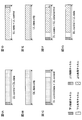
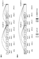
- FIG. 1 shows an example of a frame configuration (here, a time configuration) applicable in a future wireless communication system. Note that the frame configuration illustrated in FIG. 1 is an example, and the specific configuration, number, and the like of the frame configuration applicable in the present embodiment are not limited to those illustrated in FIG. For example, only a part of the frame configuration shown in FIG. 1 may be used.
- frame configurations with different channel configurations may not be explicitly defined as different frame configurations.
- a configuration in which channels and signals mapped to a block of radio resources including consecutive predetermined symbols and subcarriers are referred to as different frame configurations.
- the frame configuration is not limited to this.
- the downlink data channel and the downlink control channel are not necessarily divided in time, and may be frequency / code multiplexed in the same time interval (for example, symbol).
- the uplink data channel and the uplink control channel are not necessarily divided in time, and may be frequency / code-multiplexed in the same time interval (for example, symbol). The following description is based on an example in which different channels are divided in the time domain as shown in FIG. 1 without losing generality.
- 1A to 1C have different areas (in this case, time intervals) to which a downlink data channel for transmitting downlink data can be allocated.
- the downlink data channel may be called a downlink shared channel (PDSCH).
- PDSCH downlink shared channel
- 1D to 1G have different sections in which an uplink data channel for transmitting uplink data can be allocated.
- the uplink data channel may be referred to as an uplink shared channel (PUSCH).
- the radio base station and the user terminal use any (part or all) of the radio frame configuration of FIGS. 1A to 1C, and when performing uplink data transmission, FIG. Any (partial or all) 1G radio frame configuration can be used. Further, a plurality of frame configurations may be switched and applied.
- FIG. 1A shows a frame configuration (or subframe configuration) in which a downlink control channel and a downlink shared channel are arranged.
- the user terminal controls reception of downlink data and / or transmission of uplink data based on downlink control information (DCI) transmitted on the downlink control channel.
- FIG. 1B shows a frame configuration in which a downlink shared channel is arranged over subframes (no downlink control channel is arranged).
- FIG. 1C shows a frame configuration in which a downlink control channel, a downlink shared channel, and an uplink control channel are arranged.
- the user terminal controls reception of downlink data and / or transmission of uplink data based on downlink control information transmitted on the downlink control channel. Further, the user terminal may feed back an acknowledgment signal (HARQ-ACK) for data received on the downlink shared channel on the uplink control channel in the same time interval.
- HARQ-ACK acknowledgment signal
- a gap section may be set between the downlink shared channel and the uplink control channel.
- a gap interval may be set between the uplink control channel and the start time of the next frame or subframe.
- assignment that completes transmission / reception control may be performed within the same subframe.
- This assignment is also referred to as self-contained assignment.
- a subframe in which self-contained assignment is performed may be referred to as a self-contained subframe.
- the self-contained subframe may be referred to as, for example, a self-contained TTI, a self-contained symbol set, or other names may be used.
- the user terminal may receive DL data based on the downlink control channel and transmit a feedback signal (for example, HARQ-ACK) of the DL data.
- a feedback signal for example, HARQ-ACK
- the self-contained subframe for example, feedback with an ultra-low delay of 1 ms or less can be realized, so that the delay time can be reduced.
- FIG. 1D shows a frame configuration in which an uplink control channel and an uplink shared channel are arranged.
- the user terminal transmits uplink data on the uplink shared channel and transmits an uplink control signal on the uplink control channel.
- FIG. 1E shows a frame configuration in which an uplink shared channel is arranged over subframes (no uplink control channel is arranged).
- FIG. 1F shows a frame configuration in which a downlink control channel, an uplink shared channel, and an uplink control channel are arranged.
- the user terminal can transmit UL signals (UL data, measurement reports, etc.) in the same (or subsequent) subframes based on downlink control information transmitted on the downlink control channel. In this way, in order to enable short-time communication, assignment that completes transmission / reception control (scheduling) may be performed within the same subframe.
- FIG. 1G shows a frame configuration in which a downlink control channel and an uplink shared channel are arranged. Note that a gap interval may be set between the downlink control channel and the uplink shared channel. Although not shown, a gap interval may be set between the uplink control channel and the start time of the next frame or subframe.
- the present inventors have focused on the point that it is necessary to control transmission / reception timing flexibly in future wireless communication, and have conceived of flexible control of UL signal transmission in response to DL transmission.
- the feedback of the UL signal is controlled by notifying the user terminal of timing information related to the feedback timing of the UL signal (for example, A / N) for DL transmission.
- the user terminal can control transmission such as A / N based on timing information, the transmission direction (multiple frame configurations) and / or processing time such as UL or DL can be changed and applied flexibly. Can do.
- the radio base station can flexibly control the transmission timing of the UL signal from the user terminal based on the communication environment and the like.
- the time interval of the DL signal corresponding to the UL signal such as A / N may be a subframe (1 ms) in the existing LTE, or a period shorter than 1 ms ( For example, any one of 1-13 symbols) or a period longer than 1 ms may be used.
- the time interval may be referred to as a normal TTI, a subframe, a slot, a mini-slot, a scheduling unit, a short TTI, a minislot, or a short scheduling unit.
- a / N (HARQ-ACK, ACK / NACK) is taken as an example of a UL signal for DL transmission, but a signal to which this embodiment is applicable is limited to A / N. I can't.
- the present invention can also be applied to signals other than A / N (for example, UL data, channel state information, measurement reference signals, etc.).
- a 1st aspect demonstrates the case where the transmission timing of A / N with respect to DL transmission is controlled based on predetermined information.
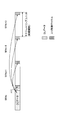
- FIG. 2 illustrates an example of A / N transmission timing candidates for DL data (for example, PDSCH).
- the A / N transmission timing for DL data transmitted at a predetermined time interval (here, SF # n) which is a DL data scheduling unit is set as downlink control information transmitted by the SF # n. Control is based on the information contained.
- a frame configuration capable of at least DL data, DL control information, and UL control information in SF # n see, for example, FIG. 1C
- at least UL control information can be transmitted in SF # n + 1 to # n + 3.
- FIGS. 1C, 1D and 1F A case where a simple frame configuration (see FIGS. 1C, 1D and 1F) is applied is shown.
- the frame configuration that can be set for each time interval is not limited to this.
- the radio base station uses timing information (also referred to as HATI-HARQ-ACK timing indicator) to specify the A / N transmission timing corresponding to the DL data in the time interval (hereinafter also referred to as subframe) in which DL data is transmitted. ) Is included in the downlink control information and notified to the user terminal.
- the user terminal can determine the timing for transmitting A / N based on the timing information (HTI) included in the downlink control information.
- the radio base station may set different values for timing information included in downlink control information transmitted to different user terminals in the same subframe. For example, when the radio base station transmits DL data to UE # 1 and UE # 2 in SF # n, it transmits downlink control information including timing information of different values to UE # 1 and UE # 2, respectively. be able to. In this case, UE # 1 and UE # 2 feed back the A / N for the DL data received by SF # n at different timings (SF).
- SF timings
- the user terminal may transmit capability information related to time required for processing DL data and / or capability information related to UL data transmission (for example, capability information related to A / N transmission timing) to the radio base station in advance.
- the radio base station can control timing information (HTI) set for each user terminal based on the capability information transmitted from the user terminal.
- the radio base station can set values corresponding to bit values (HTI values) of timing information in the user terminal in advance using higher layer signaling or the like. For example, when the timing information is set with 2 bits, the radio base station notifies the user terminal of timing information corresponding to 2 bits (4 types) by higher layer signaling, and performs downlink control for each A / N transmission timing. It is specified by information (HTI).
- the radio base station receives a predetermined value (predetermined timing information) as an A / N transmission timing until it receives capability information related to the time taken to process DL data and / or capability information related to UL data transmission from the user terminal. You may apply and you may transmit, without including HTI in downlink control information. Further, the user terminal may apply a predetermined value (predetermined timing information) as the A / N transmission timing until receiving information related to the bit value (HTI value) of the timing information from the radio base station. As the predetermined value, a predefined value (for example, after 4 subframes) can be used.
- the user terminal may perform control so that A / N for the DL data is transmitted after a predetermined timing.
- a predetermined value for example, after 4 subframes
- a / N transmission can be performed appropriately.
- timing information cannot be acquired from such downlink control information
- RRC Reconfiguration RRC reconfiguration procedure
- the initial access procedure and coverage extension control by using downlink control information without HTI, overhead can be reduced and communication quality can be improved.
- By fixing the A / N timing without using the HTI during the procedure of handover or RRC reconfiguration it is possible to prevent the recognition of timing between the base station and the user terminal from deviating.
- ⁇ Channel configuration for A / N transmission> When using a plurality of frame configurations as shown in FIG. 1, there is a possibility that a plurality of channel configurations (for example, uplink control channel configurations) used for A / N transmission are set. For example, there may be a case where the configuration of the uplink control channel is different between a frame configuration in which UL data is transmitted (for example, FIGS. 1D and 1F) and a frame configuration in which UL data is not transmitted (for example, FIG. 1C). Alternatively, a plurality of uplink control channel configurations may be set even in a frame configuration in which UL data is transmitted.
- a plurality of channel configurations may be set even in a frame configuration in which UL data is transmitted.
- the user terminal can notify the user terminal of information related to the uplink control channel configuration used for each A / N transmission.
- the user terminal can determine the uplink control channel configuration used for A / N transmission based on the predetermined information.
- the radio base station notifies the user terminal of the downlink control information including information related to the uplink control channel configuration used for A / N transmission.
- the uplink control channel configuration used for A / N transmission may be included (associated) in the timing information (HTI) that specifies the A / N transmission timing.
- the user terminal can determine the A / N transmission timing and the uplink control channel configuration to be used from the timing information (HTI) included in the downlink control information.
- the information regarding the uplink control channel configuration may be information specifying the uplink control channel configuration, or may be information regarding the frame configuration associated with a predetermined uplink control channel configuration.
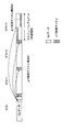
- FIG. 3 shows a case where information related to the uplink control channel configuration used for A / N transmission is included in downlink control information (here, timing information) and transmitted.
- FIG. 3 shows a case where uplink control channel configuration # 1 is set for SF # n to # n + 2 and uplink control channel configuration # 2 is set for SF # n + 3.
- the bit value specifying SF # n, # n + 1, # n + 2 as the transmission timing is associated with the uplink control channel configuration # 1, and the bit value specifying SF # n + 3 as the transmission timing Is associated with uplink control channel configuration # 2.
- the uplink control channel configuration corresponding to the bit value (HTI value) of each timing information may be set in advance from the radio base station to the user terminal using upper layer signaling or the like, or may be defined in the specification in advance. .
- information regarding the uplink control channel configuration may be provided separately from the timing information (separate bit field).
- the user terminal may determine the uplink control channel configuration used for A / N transmission based on other parameters (other information). In this case, the user terminal controls the A / N transmission timing based on timing information included in the downlink control information, and controls the uplink control channel configuration used for the A / N transmission based on other parameters. .
- information on subframes for A / N transmission can be used.
- the user terminal performs control to perform A / N transmission using a predetermined uplink control channel configuration.
- Information related to subframes used only for UL transmission can be notified in advance from the radio base station to the user terminal using higher layer signaling or the like.
- FIG. 4 shows a case where subframes used only for UL transmission are set for each predetermined period (here, 5 ⁇ time interval).
- a predetermined uplink control channel configuration here, uplink control channel configuration # 2
- uplink control channel configuration # 1 is set in other subframes. Is shown.
- the UL-dedicated subframe period, the uplink control channel configuration that can be set in each subframe, and the like are not limited thereto.
- the user terminal determines an A / N transmission timing and an uplink control channel configuration to be used based on information on a subframe period used only for UL transmission and timing information (HTI) included in downlink control information. Can do. For example, when the HTI of downlink control information transmitted in a predetermined SF in which DL data is transmitted specifies a UL-dedicated subframe, the user terminal uses uplink control channel configuration # 2. Thus, by determining the uplink control channel configuration based on the HTI and the frame configuration, it is possible to flexibly set a plurality of uplink control channel configurations.
- HTI UL transmission and timing information
- the parameter for determining the uplink control channel configuration uses other information regardless of the information of the frame configuration applied to the subframe (in FIG. 4, subframe period information used only for UL transmission). Is also possible.
- bit size codebook size, also referred to as A / N bit string
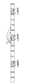
- a / N transmission timing for DL transmission at each time interval is flexibly controlled, it is also possible to feed back A / N for DL transmissions at different time intervals by using an uplink control channel at the same time interval ( (See FIG. 5).
- a / N for DL data transmitted by SF # n to # n + 3 is mapped to SF # n + 3
- a / N for DL data transmitted by SF # n + 4 and # n + 5 is SF # n + 6. Shows the case of mapping.
- the DL signal (for example, downlink control information) transmitted by SF # n includes timing information (HTI) indicating the timing for transmitting A / N corresponding to the DL data transmitted by SF # n.
- FIG. 5B maps the A / N for the DL data transmitted by SF # n + 1 to # n + 3 to SF # n + 3, and the A / N for the DL data transmitted by SF # n, # n + 4, # n + 5.
- the case of mapping to SF # n + 6 is shown.
- the user terminal can determine the A / N transmission timing corresponding to each DL data based on the timing information included in the downlink control information.
- a codebook size of A / N can be set in advance as fixed or quasi-static.
- information on the codebook size may be notified from the radio base station to the user terminal using upper layer signaling or the like.
- a setting method considering A / N bundling in the time direction, the maximum number of A / Ns that can be transmitted at a predetermined timing (or A / N)
- a setting method (method 2) that takes into account the number of time intervals corresponding to)
- a setting method (method 3) that takes into account the maximum number of A / Ns that can be transmitted at a predetermined timing and the number of CCs to be set can be used.
- the codebook size of A / N can be set to a predetermined value (for example, 1 or 2 bits).
- a predetermined value for example, 1 or 2 bits.
- MIMO is not applied (in the case of 1-layer transmission)
- the user terminal transmits 1-bit A / N using an uplink control channel at a predetermined time interval.
- MIMO is applied (in the case of multi-layer transmission)
- the user terminal applies A / N bundling in the time direction for each layer, thereby increasing 2-bit A / N at a predetermined time interval. Transmit using the control channel.
- a / N bundling means obtaining an exclusive AOR between a plurality of A / N determination results to obtain an entire A / N determination result.
- FIG. 6 is a diagram illustrating an example of A / N feedback using the method 1.
- the user terminal transmits A / N for DL data transmitted by SF # n to # n + 3 by SF # n + 3, and A / N for DL data respectively transmitted by SF # n + 4 and # n + 5. Is transmitted with SF # n + 6.
- the user terminal Based on timing information (HTI) included in downlink control information transmitted at each time interval, the user terminal transmits A / N transmission timing of each DL data (A / N corresponding to an uplink control channel at a certain time interval). ) Can be determined.
- a / N can be transmitted using an uplink control channel and / or an uplink data channel in each time interval.
- the user terminal sends 1-bit (no MIMO application) or 2-bit (MIMO application) information obtained by bundling A / N to DL data transmitted in SF # n to # n + 3 respectively in SF # n + 3.
- Send For example, the user terminal feeds back an ACK when all DL data of SF # n to # n + 3 is ACK, and NACK if any one of the DL data of SF # n to # n + 3 is NACK.
- 1-bit or 2-bit information obtained by bundling A / N for DL data transmitted by SF # n + 4 and # n + 5 is transmitted by SF # n + 6.
- the user terminal transmits A / N for DL data transmitted by SF # n + 1 to # n + 3 using SF # n + 3, and DL data transmitted using SF # n, SF # n + 4, and # n + 5, respectively.
- a / N is transmitted with SF # n + 6.
- the user terminal sends 1-bit (no MIMO application) or 2-bit (MIMO application) information obtained by bundling A / N to DL data transmitted in SF # n + 1 to # n + 3 respectively in SF # n + 3.
- 1-bit or 2-bit information obtained by bundling A / N for DL data transmitted by SF # n, # n + 4, and # n + 5 is transmitted by SF # n + 6.
- a / N feedback timing for DL transmission at a plurality of time intervals is determined based on the timing information, and bundling is applied to A / N transmitted at the same timing (or the same uplink control channel). .
- a / N transmission can be performed with a small number of bits.
- bundling only to A / Ns transmitted at the same timing (or the same uplink control channel) determined based on predetermined information such as HTI the A / N is banded between the base station and the user terminal. A common understanding about the ringed data can be ensured and A / N can be fed back correctly.
- the radio base station may notify the user terminal by including a DL assignment index (DAI: Downlink Assignment Indicator (Index)) in downlink control information for scheduling DL data.
- DAI Downlink Assignment Indicator
- the DAI is a value assigned to each scheduled subframe, and is used to identify (count) the scheduled subframe.
- Information used for scheduling subframe counting is also called a counter DAI (counter DAI).
- the radio base station sets and transmits a counter DAI corresponding to each subframe in the downlink control information of the subframe in which DL data is scheduled.
- the counter DAI included in the downlink control information of each subframe can be set in ascending order based on the subframe number and the like.
- the counter that cannot be detected when the values (cumulative value and count value) of the counter DAI included in the downlink control information of each subframe are not continuous. It can be determined that a subframe corresponding to DAI has been misdetected.
- the user terminal can perform A / N feedback by determining NACK for a time interval in which detection is missed.
- the counter DAI is a DL data group that transmits A / N at the same timing (or the same uplink control channel) (in FIG. 6A, an A / N transmission group composed of SF # n to SF # n + 3, SF It can be applied in units of (A / N transmission group composed of # n + 4 to SFn + 5).
- the subframe (SF #) in which the counter DAI included in the downlink control information is the largest among the scheduled subframes (SF # n to # n + 3 in FIG. 6A).
- n + 3 is detected incorrectly, the user terminal cannot grasp the detection error. Therefore, in order to appropriately control A / N transmission when the last subframe scheduled in the A / N transmission group (subframe with the largest counter DAI) is missed, the following option 1- Any of 3 may be applied.
- a / N is transmitted using an uplink control channel corresponding to downlink control information (or downlink control channel) for scheduling the last DL data. N transmissions are performed.
- an uplink control channel resource used for A / N transmission corresponding to each DL data may be set.
- the radio base station may determine an A / N detection error in the user terminal (a subframe in which the user terminal last received DL data) based on a resource to which A / N fed back from the user terminal is allocated. it can. For example, in FIG.
- an uplink control channel resource corresponding to the downlink control information of SF # n to # n + 3 is set, and the user terminal uplinks corresponding to DL data (or downlink control information) at the last received time interval.
- a / N transmission is performed using control channel resources.
- Option 2 sets a total DAI indicating information on the number of scheduled subframes (total number).
- the radio base station includes information indicating the number of subframes scheduled for DL transmission (total DAI) in the downlink control information of each subframe and notifies the user terminal.
- the user terminal can determine the number of DL data (time interval) actually scheduled in each A / N transmission group.
- information for identifying downlink control information (or downlink control channel) for scheduling the DL data to be transmitted last is It is included in the downlink control information and notified to the user terminal.
- the radio base station toggles LDI included in downlink control information for scheduling DL data last, and does not toggle LDI included in downlink control information for scheduling other DL data.
- LDI is included in downlink control information transmitted in other subframes. It is possible to notify the user terminal including 0.
- the A / N codebook size is set to a predetermined value (for example, M or 2M bits) in consideration of the maximum value of the number of A / Ns that can be transmitted at a predetermined timing (or the number of time intervals corresponding to A / N). can do.
- MIMO is not applied (in the case of 1-layer transmission)
- the user terminal transmits M-bit A / N using an uplink control channel at a predetermined time interval.
- MIMO in the case of multi-layer transmission
- the user terminal transmits, for example, 2 Mbit A / N using an uplink control channel at a predetermined time interval.
- M is set to a value equal to or greater than the maximum number of A / Ns transmitted at one timing (same timing).
- M can be set to a value equal to or greater than 2 N or 2 ⁇ 2 N.
- the user terminal transmits A / N for DL data transmitted by SF # n to # n + 3 by SF # n + 3, and transmitted by SF # n + 4 and # n + 5, respectively.
- a / N for data is transmitted by SF # n + 6.
- the user terminal sets a range for performing A / N feedback at the same timing (also referred to as a window, a HARQ-ACK feedback window, and a HARQ-ACK bundling window). For example, when detecting downlink control information for scheduling DL data corresponding to a predetermined HTI value, the user terminal determines a window including a time interval in which the DL data is scheduled. Then, an A / N bit corresponding to the window is generated to control feedback.
- the HARQ-ACK bundling window can be determined based on the value of M. For example, the user terminal sets M consecutive time intervals including at least a time interval at which timing information (HTI) is received as a window. At this time, a time interval that continues M times from a predetermined time interval (for example, a time interval for performing A / N transmission) may be set as a window.
- a predetermined time interval for example, a time interval for performing A / N transmission
- a window is set in the range of SF # n to SF # n + 3 for the A / N transmission of SF # n + 3, and the range of SF # n + 3 to SF # n + 6 for the A / N transmission of SF # n + 6.
- the user terminal controls A / N transmission (for example, NACK transmission) by setting a window for a time interval (for example, SF # n + 6) in which DL data is not actually scheduled.
- the user terminal can control the arrangement order of A / N bits based on the HTI value. For example, the user terminal can generate each A / N bit string in descending order from A / N bits corresponding to DL data having a large HTI value.
- Method 3 In Method 3, based on the number of CCs (cells) set in the user terminal in addition to the number of A / Ns (or the number of time intervals corresponding to A / N) that can be transmitted at the predetermined timing in Method 2 above, A / N Set codebook size as fixed or semi-static. For example, the A / N codebook size is set to M ⁇ K bits (MIMO not applied) or 2M ⁇ K bits (MIMO applied).
- K corresponds to the number of CCs set in the user terminal.
- the number of CCs can be the number of CCs sharing the same uplink control channel (for example, CCs set in CCs of cell groups configured to include cells that perform PUCCH transmission).
- M can be defined as in Method 2 above.
- the HARQ-ACK bundling window can be set in the same manner as in method 2. That is, in method 3, the A / N is controlled by increasing the A / N codebook size by the number of CCs in method 2.
- the value (HTI value) of timing information included in downlink control information (or downlink control channel) for scheduling DL data can be a common value between different CCs.
- the user terminal can perform A / N transmission in different CCs using the same uplink control channel at the same time interval.
- the user terminal may dynamically control the A / N transmission by dynamically setting the A / N codebook size.
- the user terminal determines a codebook size corresponding to A / N to be actually fed back based on the number of time intervals (scheduling units) in which DL data is scheduled.
- the user terminal can determine the A / N codebook size based on timing information (HTI) and counter DAI included in downlink control information for scheduling DL data.
- the counter DAI can be set in the same manner as in Method 1 above.
- Option 1 of Method 1 is used. Any of -3 may be applied.
- the user terminal can determine the codebook size of each A / N transmission based on the total DAI in addition to the HTI and the counter DAI.
- the transmission power of the uplink signal is controlled based on a transmission power control (TPC) command or the like included in the downlink control information.
- the TPC command for controlling the transmission power of the uplink control channel (PUCCH) is a downlink control channel (PDCCH / EPDCCH) for transmitting DCI format 1A / 1B / 1D / 1 / 2A / 2 / 2B / 2C / 2D, DCI format 6 -1A is included in the downlink control channel (MPDCCH) and DCI format 3 / 3A is included in the downlink control channel (PDCCH / MPDCCH).
- the CRC parity bits of DCI format 3 / 3A are scrambled by TPC RNTI (TPC-PUCCH-RNTI).
- a predetermined value e.g., k m
- SF # i-k m a predetermined value only previous subframe
- g (i) is the current PUCCH power control adjustment state
- g (0) corresponds to the first value after reset
- M corresponds to the number of subframes corresponding to the TPC command.
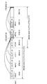
- M and k m applies the values defined for each UL subframe in accordance with the UL / DL configurations (see FIG. 8).
- Figure 8 is an example of a table M, where k m is defined for each configuration UL / DL applied in PUCCH transmission in each UL subframe in TDD.
- the user terminal can control the transmission power of PUCCH using TPC commands transmitted in a plurality of DL subframes (for example, Rel. 8). ).
- the user terminal uses the TPC command transmitted in one DL subframe (for example, the earliest DL subframe in the time direction) to transmit the PUCCH transmission power.
- the bit values of other TPC commands can be used for other purposes (for example, designation of PUCCH resources) (Rel. 10 and later).
- the transmission power of the uplink signal is determined based on the transmission power control (TPC) command or the like included in the downlink control information transmitted in a predetermined subframe.
- TPC transmission power control
- a / N feedback when the timing of A / N feedback is dynamically controlled, how to use the TPC command is not yet defined. For example, when A / N transmission timing is controlled based on timing information (HTI) included in downlink control information, how to control uplink transmission power in the A / N transmission (for example, uplink control channel transmission power). It will be a problem.
- TPC transmission power control
- the TPC command included in the downlink control information is applied at the same timing as the A / N feedback timing notified by the timing information (HTI) (method 1).
- the TPC command included in the downlink control information is applied at a predetermined timing regardless of the A / N feedback timing notified by the timing information (HTI) (method 2).
- the timing (SF) for transmitting A / N corresponding to the DL data of SF # n is determined based on the timing information (HTI) included in the downlink control information transmitted by the SF # n ( (See FIG. 9).
- the TPC command included in the downlink control information of SF # n is used for transmission power control of the SF UL signal (for example, uplink control channel) specified by HTI.
- the TPC command included in the downlink control information of SF # n is changed to A of SF # n + 3. This is applied to transmission power control of / N transmission (for example, uplink control channel).
- the transmission power of the uplink control channel is controlled using the TPC command included in the downlink control information for scheduling any one of the DL data.
- the transmission power of the uplink control channel may be controlled using a plurality of TPC commands included in downlink control information for scheduling each DL data.
- the user terminal can be controlled to reflect the TPC command in the transmission power.
- the TPC command included in the downlink control information of SF # n is used for transmission power control of a UL signal (for example, uplink control channel) in a predetermined SF regardless of the SF specified by HTI.
- the user terminal secures time required for transmission power control and / or calculation of power headroom report (PHR) information related to transmission power. Can do.
- PHR power headroom report
- wireless communication system Wireless communication system
- the radio communication method according to each of the above aspects is applied.
- wireless communication method which concerns on each said aspect may be applied independently, respectively, and may be applied in combination.
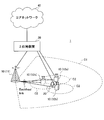
- FIG. 10 is a diagram illustrating an example of a schematic configuration of the wireless communication system according to the present embodiment.
- carrier aggregation in which a plurality of basic frequency blocks (component carriers (CC)) each having a system bandwidth (for example, 20 MHz) of the LTE system as one unit are integrated and / or one or more Dual connectivity (DC) using a plurality of cell groups (CG) including CC can be applied.
- the wireless communication system 1 is called SUPER 3G, LTE-A (LTE-Advanced), IMT-Advanced, 4G, 5G, FRA (Future Radio Access), NR (New Radio Access Technology), etc. Also good.
- the radio communication system 1 shown in FIG. 10 includes a radio base station 11 that forms a macro cell C1, and radio base stations 12a to 12c that are arranged in the macro cell C1 and form a small cell C2 that is narrower than the macro cell C1. .
- the user terminal 20 is arrange
- the user terminal 20 can be connected to both the radio base station 11 and the radio base station 12. It is assumed that the user terminal 20 uses the macro cell C1 and the small cell C2 that use different frequencies simultaneously by CA or DC. In addition, the user terminal 20 can apply CA or DC using a plurality of cells (CC) (for example, two or more CCs). Further, the user terminal can use the license band CC and the unlicensed band CC as a plurality of cells.
- CC cells
- the user terminal 20 can perform communication using time division duplex (TDD) or frequency division duplex (FDD) in each cell.
- TDD time division duplex
- FDD frequency division duplex
- the TDD cell and the FDD cell may be referred to as a TDD carrier (frame configuration type 2), an FDD carrier (frame configuration type 1), and the like, respectively.
- each cell a single neurology may be applied, or a plurality of different neurology may be applied.
- the neurology is a parameter in the frequency direction and the time direction, such as a subcarrier interval, a symbol length, a cyclic prefix length, and a subframe length.
- Communication between the user terminal 20 and the radio base station 11 can be performed using a carrier having a relatively low frequency band (for example, 2 GHz) and a narrow bandwidth (referred to as an existing carrier or a legacy carrier).
- a carrier having a wide bandwidth in a relatively high frequency band for example, 3.5 GHz, 5 GHz, 30 to 70 GHz, etc.
- the same carrier as that between the base station 11 and the base station 11 may be used.
- the configuration of the frequency band used by each radio base station is not limited to this.
- a wired connection for example, an optical fiber compliant with CPRI (Common Public Radio Interface), an X2 interface, etc.
- a wireless connection It can be set as the structure to do.
- the radio base station 11 and each radio base station 12 are connected to the higher station apparatus 30 and connected to the core network 40 via the higher station apparatus 30.
- the upper station device 30 includes, for example, an access gateway device, a radio network controller (RNC), a mobility management entity (MME), and the like, but is not limited thereto.
- RNC radio network controller
- MME mobility management entity
- Each radio base station 12 may be connected to the higher station apparatus 30 via the radio base station 11.
- the radio base station 11 is a radio base station having a relatively wide coverage, and may be called a macro base station, an aggregation node, an eNB (eNodeB), a transmission / reception point, or the like.
- the radio base station 12 is a radio base station having local coverage, and includes a small base station, a micro base station, a pico base station, a femto base station, a HeNB (Home eNodeB), an RRH (Remote Radio Head), and transmission / reception. It may be called a point.
- the radio base stations 11 and 12 are not distinguished, they are collectively referred to as a radio base station 10.
- Each user terminal 20 is a terminal compatible with various communication methods such as LTE and LTE-A, and may include not only a mobile communication terminal but also a fixed communication terminal. Further, the user terminal 20 can perform inter-terminal communication (D2D) with other user terminals 20.
- D2D inter-terminal communication
- OFDMA orthogonal frequency division multiple access
- SC-FDMA single carrier-frequency division multiple access
- OFDMA is a multi-carrier transmission scheme that performs communication by dividing a frequency band into a plurality of narrow frequency bands (subcarriers) and mapping data to each subcarrier.
- SC-FDMA is a single-carrier transmission scheme that reduces interference between terminals by dividing the system bandwidth into bands consisting of one or continuous resource blocks for each terminal and using a plurality of terminals with mutually different bands. is there.
- the uplink and downlink radio access schemes are not limited to these combinations, and OFDMA may be used in the UL.
- a DL shared channel (PDSCH: Physical Downlink Shared Channel, also referred to as DL data channel) shared by each user terminal 20, a broadcast channel (PBCH: Physical Broadcast Channel), L1 / L2 A control channel or the like is used.
- PDSCH Physical Downlink Shared Channel
- PBCH Physical Broadcast Channel
- SIB System Information Block
- MIB Master Information Block
- L1 / L2 control channels include DL control channels (PDCCH (Physical Downlink Control Channel), EPDCCH (Enhanced Physical Downlink Control Channel)), PCFICH (Physical Control Format Indicator Channel), PHICH (Physical Hybrid-ARQ Indicator Channel), etc. .
- Downlink control information (DCI: Downlink Control Information) including scheduling information of PDSCH and PUSCH is transmitted by PDCCH.
- the number of OFDM symbols used for PDCCH is transmitted by PCFICH.
- the EPDCCH is frequency-division multiplexed with the PDSCH, and is used for transmission of DCI and the like as with the PDCCH.
- Retransmission control information for example, at least one of A / N, NDI, HPN, and redundant version (RV)
- the UL signal for example, PUSCH
- Retransmission control information for example, at least one of A / N, NDI, HPN, and redundant version (RV)
- PUSCH Retransmission control information
- PHICH Physical Downlink Control Channel
- PDCCH Physical Downlink Control Channel
- a UL shared channel (PUSCH: Physical Uplink Shared Channel, also referred to as a UL data channel) shared by each user terminal 20, a UL control channel (PUCCH: Physical Uplink Control Channel), random An access channel (PRACH: Physical Random Access Channel) or the like is used.
- User data and higher layer control information are transmitted by the PUSCH.
- Uplink control information including at least one of retransmission control information (eg, A / N), channel state information (CSI), and scheduling request (SR) of a DL signal (eg, PDSCH) is PUSCH. Or it is transmitted by PUCCH.
- the PRACH can transmit a random access preamble for establishing a connection with a cell.
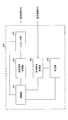
- FIG. 11 is a diagram illustrating an example of the overall configuration of the radio base station according to the present embodiment.
- the radio base station 10 includes a plurality of transmission / reception antennas 101, an amplifier unit 102, a transmission / reception unit 103, a baseband signal processing unit 104, a call processing unit 105, and a transmission path interface 106. Note that each of the transmission / reception antenna 101, the amplifier unit 102, and the transmission / reception unit 103 may include one or more.
- User data transmitted from the radio base station 10 to the user terminal 20 via the downlink is input from the higher station apparatus 30 to the baseband signal processing unit 104 via the transmission path interface 106.
- PDCP Packet Data Convergence Protocol
- RLC Radio Link Control
- MAC Medium Access
- Retransmission control for example, HARQ (Hybrid Automatic Repeat reQuest) transmission processing
- HARQ Hybrid Automatic Repeat reQuest
- the DL control signal is also subjected to transmission processing such as channel coding and inverse fast Fourier transform, and is transferred to the transmission / reception unit 103.
- the transmission / reception unit 103 converts the baseband signal output by precoding for each antenna from the baseband signal processing unit 104 to a radio frequency band and transmits the converted signal.
- the radio frequency signal frequency-converted by the transmission / reception unit 103 is amplified by the amplifier unit 102 and transmitted from the transmission / reception antenna 101.
- the transmitter / receiver, the transmission / reception circuit, or the transmission / reception device can be configured based on common recognition in the technical field according to the present invention.
- the transmission / reception part 103 may be comprised as an integral transmission / reception part, and may be comprised from a transmission part and a receiving part.
- the radio frequency signal received by the transmission / reception antenna 101 is amplified by the amplifier unit 102.
- the transmission / reception unit 103 receives the UL signal amplified by the amplifier unit 102.
- the transmission / reception unit 103 converts the frequency of the received signal into a baseband signal and outputs it to the baseband signal processing unit 104.
- the baseband signal processing unit 104 performs Fast Fourier Transform (FFT) processing, Inverse Discrete Fourier Transform (IDFT) processing, error correction on UL data included in the input UL signal. Decoding, MAC retransmission control reception processing, RLC layer and PDCP layer reception processing are performed and transferred to the upper station apparatus 30 via the transmission path interface 106.
- the call processing unit 105 performs call processing such as communication channel setting and release, state management of the radio base station 10, and radio resource management.
- the transmission path interface 106 transmits and receives signals to and from the higher station apparatus 30 via a predetermined interface.
- the transmission path interface 106 transmits and receives (backhaul signaling) signals to and from the adjacent radio base station 10 via an interface between base stations (for example, an optical fiber compliant with CPRI (Common Public Radio Interface), X2 interface). Also good.
- CPRI Common Public Radio Interface
- X2 interface also good.
- the transmission / reception unit 103 receives at least one of information (HTI) regarding A / N transmission timing corresponding to DL transmission, counter DAI, total DAI, LDI, and TPC command for controlling transmission power during A / N transmission. Including downlink control information. In addition, the transmission / reception unit 103 receives uplink control information (UCI) including the A / N of the DL shared channel.
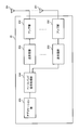
- FIG. 12 is a diagram illustrating an example of a functional configuration of the radio base station according to the present embodiment.
- FIG. 12 mainly shows functional blocks of characteristic portions in the present embodiment, and the wireless base station 10 also has other functional blocks necessary for wireless communication.
- the baseband signal processing unit 104 includes a control unit 301, a transmission signal generation unit 302, a mapping unit 303, a reception signal processing unit 304, and a measurement unit 305.
- the control unit 301 controls the entire radio base station 10.
- the control unit 301 includes, for example, DL signal generation by the transmission signal generation unit 302, DL signal mapping by the mapping unit 303, UL signal reception processing (for example, demodulation) by the reception signal processing unit 304, and measurement unit 305. Control the measurement.
- control unit 301 schedules the user terminal 20.
- control unit 301 performs PUSCH and / or PDSCH scheduling for the user terminal 20.
- control unit 301 controls A / N transmission timing corresponding to DL transmission and also controls transmission of information (HTI) related to the transmission timing (see FIG. 2).
- the control part 301 can be comprised from the controller, the control circuit, or control apparatus demonstrated based on the common recognition in the technical field which concerns on this invention.
- transmission signal generation unit 302 Based on an instruction from control unit 301, transmission signal generation unit 302 generates a DL signal (including DL data, DCI, UL data retransmission control information, and higher layer control information) and outputs the DL signal to mapping unit 303. .
- the transmission signal generation unit 302 can be a signal generator, a signal generation circuit, or a signal generation device described based on common recognition in the technical field according to the present invention.
- the mapping unit 303 stores the DL signal generated by the transmission signal generation unit 302 (for example, DL data, DCI, UL data retransmission control information, higher layer control information, etc.) in a predetermined manner. And is output to the transceiver 103.
- the mapping unit 303 can be a mapper, a mapping circuit, or a mapping device described based on common recognition in the technical field according to the present invention.
- the reception signal processing unit 304 performs reception processing (for example, demapping, demodulation, decoding, etc.) on the UL signal (for example, UL data, UCI, etc.) transmitted from the user terminal 20. Specifically, the reception signal processing unit 304 performs UL signal reception processing based on the neurology set in the user terminal 20. The reception signal processing unit 304 may output a reception signal or a signal after reception processing to the measurement unit 305. Reception signal processing section 304 performs reception processing on the A / N of the DL signal and outputs ACK or NACK to control section 301.
- reception processing for example, demapping, demodulation, decoding, etc.
- the measurement unit 305 performs measurement on the received signal.
- the measurement part 305 can be comprised from the measuring device, measurement circuit, or measurement apparatus demonstrated based on common recognition in the technical field which concerns on this invention.
- the measurement unit 305 measures the UL channel quality based on, for example, the reception power (for example, RSRP (Reference Signal Received Power)) and / or the reception quality (for example, RSRQ (Reference Signal Received Quality)) of the UL reference signal. May be.
- the measurement result may be output to the control unit 301.
- FIG. 13 is a diagram illustrating an example of the overall configuration of the user terminal according to the present embodiment.
- the user terminal 20 includes a plurality of transmission / reception antennas 201 for MIMO transmission, an amplifier unit 202, a transmission / reception unit 203, a baseband signal processing unit 204, and an application unit 205.
- the radio frequency signals received by the plurality of transmission / reception antennas 201 are each amplified by the amplifier unit 202.
- Each transmitting / receiving unit 203 receives the DL signal amplified by the amplifier unit 202.
- the transmission / reception unit 203 converts the frequency of the received signal into a baseband signal and outputs it to the baseband signal processing unit 204.
- the baseband signal processing unit 204 performs FFT processing, error correction decoding, retransmission control reception processing, and the like on the input baseband signal.
- the DL data is transferred to the application unit 205.
- the application unit 205 performs processing related to layers higher than the physical layer and the MAC layer. Broadcast information is also transferred to the application unit 205.
- UL data is input from the application unit 205 to the baseband signal processing unit 204.
- the baseband signal processing unit 204 performs retransmission control transmission processing (for example, HARQ transmission processing), channel coding, rate matching, puncturing, discrete Fourier transform (DFT) processing, IFFT processing, and the like. Are transferred to each transmitting / receiving unit 203.
- UCI (for example, at least one of DL retransmission control information, CSI, and SR) is also subjected to channel coding, rate matching, puncturing, DFT processing, IFFT processing, and the like, and transferred to each transmitting / receiving section 203.
- the transmission / reception unit 203 converts the baseband signal output from the baseband signal processing unit 204 into a radio frequency band and transmits it.
- the radio frequency signal frequency-converted by the transmission / reception unit 203 is amplified by the amplifier unit 202 and transmitted from the transmission / reception antenna 201.
- the transmission / reception unit 203 receives at least one of information (HTI) related to A / N transmission timing corresponding to DL transmission, counter DAI, total DAI, LDI, and TPC command for controlling transmission power during A / N transmission. Including downlink control information. Further, the transmission / reception unit 203 transmits uplink control information (UCI) including A / N corresponding to the DL shared channel.
- the transmission / reception unit 203 can be a transmitter / receiver, a transmission / reception circuit, or a transmission / reception device described based on common recognition in the technical field according to the present invention. Further, the transmission / reception unit 203 may be configured as an integral transmission / reception unit, or may be configured from a transmission unit and a reception unit.
- FIG. 14 is a diagram illustrating an example of a functional configuration of the user terminal according to the present embodiment.
- FIG. 14 mainly shows functional blocks of characteristic portions in the present embodiment, and the user terminal 20 also has other functional blocks necessary for wireless communication.
- the baseband signal processing unit 204 included in the user terminal 20 includes a control unit 401, a transmission signal generation unit 402, a mapping unit 403, a reception signal processing unit 404, and a measurement unit 405. I have.
- the control unit 401 controls the entire user terminal 20. For example, the control unit 401 controls generation of the UL signal by the transmission signal generation unit 402, mapping of the UL signal by the mapping unit 403, reception processing of the DL signal by the reception signal processing unit 404, and measurement by the measurement unit 405.
- the control unit 401 controls A / N transmission for downlink data.
- the control unit 401 controls A / N transmission timing based on timing information (HTI) included in downlink control information (see FIGS. 2 and 5).
- TTI timing information
- the control unit 401 controls to transmit A / N at a predetermined timing set in advance.
- the control unit 401 can determine an uplink control channel to be used for A / N based on information related to the uplink control channel configuration included in the downlink control information and / or parameters different from the downlink control information. (See FIGS. 3 and 4).
- control unit 401 determines a feedback window and / or codebook size corresponding to A / N based on at least timing information included in downlink control information (see FIG. 7).
- the control unit 401 controls the A / N codebook size based on at least the timing information included in the downlink control information and the counter DAI. Further, the control unit 401 performs A / N based on the transmission power control command included in the same downlink control information as the timing information (HTI) or the transmission power control command included in the downlink control information transmitted before a predetermined period. (See FIG. 9).
- the control unit 401 can be configured by a controller, a control circuit, or a control device described based on common recognition in the technical field according to the present invention.
- the transmission signal generation unit 402 generates a UL signal (including UL data, UCI, UL reference signal, etc.) based on an instruction from the control unit 401 (for example, encoding, rate matching, puncturing, modulation, etc.). And output to the mapping unit 403.
- the transmission signal generation unit 402 may be a signal generator, a signal generation circuit, or a signal generation device described based on common recognition in the technical field according to the present invention.
- the mapping unit 403 maps the UL signal generated by the transmission signal generation unit 402 to a radio resource based on an instruction from the control unit 401, and outputs it to the transmission / reception unit 203.
- the mapping unit 403 may be a mapper, a mapping circuit, or a mapping device described based on common recognition in the technical field according to the present invention.
- the reception signal processing unit 404 performs reception processing (eg, demapping, demodulation, decoding, etc.) on the DL signal (DL data, DCI, higher layer control information, etc.).
- the reception signal processing unit 404 outputs information received from the radio base station 10 to the control unit 401.
- the reception signal processing unit 404 outputs, for example, broadcast information, system information, higher layer control information by higher layer signaling such as RRC signaling, physical layer control information (L1 / L2 control information), and the like to the control unit 401.
- the received signal processing unit 404 can be configured by a signal processor, a signal processing circuit, or a signal processing device described based on common recognition in the technical field according to the present invention. Further, the reception signal processing unit 404 can constitute a reception unit according to the present invention.
- the measurement unit 405 measures the channel state based on a reference signal (for example, CRS or / and CSI-RS) from the radio base station 10 and outputs the measurement result to the control unit 401.
- a reference signal for example, CRS or / and CSI-RS
- the measuring unit 405 can be composed of a signal processor, a signal processing circuit or a signal processing device, and a measuring device, a measurement circuit or a measuring device which are explained based on common recognition in the technical field according to the present invention.
- each functional block may be realized by one device physically and / or logically coupled, and two or more devices physically and / or logically separated may be directly and / or indirectly. (For example, wired and / or wireless) and may be realized by these plural devices.
- the radio base station, user terminal, and the like in this embodiment may function as a computer that performs processing of the radio communication method of the present invention.
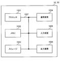
- FIG. 15 is a diagram illustrating an example of a hardware configuration of the radio base station and the user terminal according to the present embodiment.
- the wireless base station 10 and the user terminal 20 described above may be physically configured as a computer device including a processor 1001, a memory 1002, a storage 1003, a communication device 1004, an input device 1005, an output device 1006, a bus 1007, and the like. Good.
- the term “apparatus” can be read as a circuit, a device, a unit, or the like.
- the hardware configurations of the radio base station 10 and the user terminal 20 may be configured to include one or a plurality of each device illustrated in the figure, or may be configured not to include some devices.
- processor 1001 may be implemented by one or more chips.
- each function in the radio base station 10 and the user terminal 20 reads predetermined software (program) on hardware such as the processor 1001 and the memory 1002, so that the processor 1001 performs computation and communication by the communication device 1004.
- predetermined software program
- it is realized by controlling data reading and / or writing in the memory 1002 and the storage 1003.
- the processor 1001 controls the entire computer by operating an operating system, for example.
- the processor 1001 may be configured by a central processing unit (CPU) including an interface with peripheral devices, a control device, an arithmetic device, a register, and the like.
- CPU central processing unit
- the baseband signal processing unit 104 (204) and the call processing unit 105 described above may be realized by the processor 1001.
- the processor 1001 reads programs (program codes), software modules, data, and the like from the storage 1003 and / or the communication device 1004 to the memory 1002, and executes various processes according to these.
- programs program codes
- software modules software modules
- data data
- the like data
- the control unit 401 of the user terminal 20 may be realized by a control program stored in the memory 1002 and operated by the processor 1001, and may be realized similarly for other functional blocks.
- the memory 1002 is a computer-readable recording medium such as a ROM (Read Only Memory), an EPROM (Erasable Programmable ROM), an EEPROM (Electrically EPROM), a RAM (Random Access Memory), or any other suitable storage medium. It may be configured by one.
- the memory 1002 may be called a register, a cache, a main memory (main storage device), or the like.
- the memory 1002 can store programs (program codes), software modules, and the like that can be executed to implement the wireless communication method according to an embodiment of the present invention.
- the storage 1003 is a computer-readable recording medium such as a flexible disk, a floppy (registered trademark) disk, a magneto-optical disk (for example, a compact disk (CD-ROM (Compact Disc ROM)), a digital versatile disk, Blu-ray® disk), removable disk, hard disk drive, smart card, flash memory device (eg, card, stick, key drive), magnetic stripe, database, server, or other suitable storage medium It may be constituted by.
- the storage 1003 may be referred to as an auxiliary storage device.
- the communication device 1004 is hardware (transmission / reception device) for performing communication between computers via a wired and / or wireless network, and is also referred to as a network device, a network controller, a network card, a communication module, or the like.
- the communication device 1004 includes, for example, a high-frequency switch, a duplexer, a filter, a frequency synthesizer, etc., in order to realize frequency division duplex (FDD) and / or time division duplex (TDD). It may be configured.
- FDD frequency division duplex
- TDD time division duplex
- the transmission / reception antenna 101 (201), the amplifier unit 102 (202), the transmission / reception unit 103 (203), the transmission path interface 106, and the like described above may be realized by the communication device 1004.
- the input device 1005 is an input device (for example, a keyboard, a mouse, a microphone, a switch, a button, a sensor, etc.) that accepts an input from the outside.
- the output device 1006 is an output device (for example, a display, a speaker, an LED (Light Emitting Diode) lamp, etc.) that performs output to the outside.
- the input device 1005 and the output device 1006 may have an integrated configuration (for example, a touch panel).
- each device such as the processor 1001 and the memory 1002 is connected by a bus 1007 for communicating information.
- the bus 1007 may be configured with a single bus or may be configured with different buses between apparatuses.
- the radio base station 10 and the user terminal 20 include a microprocessor, a digital signal processor (DSP), an ASIC (Application Specific Integrated Circuit), a PLD (Programmable Logic Device), an FPGA (Field Programmable Gate Array), and the like. It may be configured including hardware, and a part or all of each functional block may be realized by the hardware. For example, the processor 1001 may be implemented by at least one of these hardware.
- DSP digital signal processor
- ASIC Application Specific Integrated Circuit
- PLD Programmable Logic Device
- FPGA Field Programmable Gate Array
- the channel and / or symbol may be a signal (signaling).
- the signal may be a message.
- the reference signal may be abbreviated as RS (Reference Signal), and may be referred to as a pilot, a pilot signal, or the like depending on an applied standard.
- a component carrier CC: Component Carrier
- CC Component Carrier
- the radio frame may be configured with one or a plurality of periods (frames) in the time domain.
- Each of the one or more periods (frames) constituting the radio frame may be referred to as a subframe.
- a subframe may be composed of one or more slots in the time domain.
- the slot may be configured with one or a plurality of symbols (OFDM (Orthogonal Frequency Division Multiplexing) symbol, SC-FDMA (Single Carrier Frequency Division Multiple Access) symbol, etc.) in the time domain).
- OFDM Orthogonal Frequency Division Multiplexing
- SC-FDMA Single Carrier Frequency Division Multiple Access
- the radio frame, subframe, slot, and symbol all represent a time unit when transmitting a signal.
- Different names may be used for the radio frame, the subframe, the slot, and the symbol.
- one subframe may be referred to as a transmission time interval (TTI)
- TTI transmission time interval
- a plurality of consecutive subframes may be referred to as a TTI
- one slot may be referred to as a TTI.
- the subframe or TTI may be a subframe (1 ms) in the existing LTE, a period shorter than 1 ms (for example, 1-13 symbols), or a period longer than 1 ms.
- a unit representing TTI may be called a slot, a minislot, a scheduling unit, or the like instead of a subframe.
- TTI means, for example, a minimum time unit for scheduling in wireless communication.
- a radio base station performs scheduling to allocate radio resources (frequency bandwidth, transmission power, etc. that can be used in each user terminal) to each user terminal in units of TTI.
- the definition of TTI is not limited to this.
- the TTI may be a transmission time unit of a channel-encoded data packet (transport block), or may be a processing unit such as scheduling or link adaptation.
- a TTI having a time length of 1 ms may be called a normal TTI (TTI in LTE Rel. 8-12), a normal TTI, a long TTI, a normal subframe, a normal subframe, or a long subframe.
- a TTI shorter than a normal TTI may be called a shortened TTI, a short TTI, a shortened subframe, a short subframe, or the like.
- a long TTI eg, normal TTI, subframe, etc.
- a short TTI eg, shortened TTI
- a resource block is a resource allocation unit in the time domain and the frequency domain, and may include one or a plurality of continuous subcarriers (subcarriers) in the frequency domain. Further, the RB may include one or a plurality of symbols in the time domain, and may have a length of one slot, one subframe, or 1 TTI. One TTI and one subframe may each be composed of one or a plurality of resource blocks.
- the RB may be called a physical resource block (PRB: Physical RB), a PRB pair, an RB pair, or the like.
- the resource block may be composed of one or a plurality of resource elements (RE: Resource Element).
- RE Resource Element
- 1RE may be a radio resource region of 1 subcarrier and 1 symbol.
- the structure of the above-described radio frame, subframe, slot, symbol, and the like is merely an example.
- the configuration such as the cyclic prefix (CP) length can be changed in various ways.
- information, parameters, and the like described in this specification may be represented by absolute values, may be represented by relative values from a predetermined value, or may be represented by other corresponding information.
- the radio resource may be indicated by a predetermined index.
- mathematical formulas and the like using these parameters may differ from those explicitly disclosed herein.
- PUCCH Physical Uplink Control Channel
- PDCCH Physical Downlink Control Channel
- information elements can be identified by any suitable name, so the various channels and information elements assigned to them.
- the name is not limiting in any way.
- information, signals, etc. can be output from the upper layer to the lower layer and / or from the lower layer to the upper layer.
- Information, signals, and the like may be input / output via a plurality of network nodes.
- the input / output information, signals, etc. may be stored in a specific location (for example, a memory), or may be managed by a management table. Input / output information, signals, and the like can be overwritten, updated, or added. The output information, signals, etc. may be deleted. Input information, signals, and the like may be transmitted to other devices.
- information notification includes physical layer signaling (eg, downlink control information (DCI), uplink control information (UCI)), upper layer signaling (eg, RRC (Radio Resource Control) signaling), It may be implemented by broadcast information (Master Information Block (MIB), System Information Block (SIB), etc.), MAC (Medium Access Control) signaling), other signals, or a combination thereof.
- DCI downlink control information
- UCI uplink control information
- RRC Radio Resource Control
- MIB Master Information Block
- SIB System Information Block
- MAC Medium Access Control
- the physical layer signaling may be referred to as L1 / L2 (Layer 1 / Layer 2) control information (L1 / L2 control signal), L1 control information (L1 control signal), or the like.
- the RRC signaling may be referred to as an RRC message, and may be, for example, an RRC connection setup (RRCConnectionSetup) message, an RRC connection reconfiguration (RRCConnectionReconfiguration) message, or the like.
- the MAC signaling may be notified by, for example, a MAC control element (MAC CE (Control Element)).
- notification of predetermined information is not limited to explicitly performed, but implicitly (for example, by not performing notification of the predetermined information or another (By notification of information).
- the determination may be performed by a value represented by 1 bit (0 or 1), or may be performed by a boolean value represented by true or false.
- the comparison may be performed by numerical comparison (for example, comparison with a predetermined value).
- software, instructions, information, etc. may be sent and received via a transmission medium.
- software can use websites, servers using wired technology (coaxial cable, fiber optic cable, twisted pair, digital subscriber line (DSL), etc.) and / or wireless technology (infrared, microwave, etc.) , Or other remote sources, these wired and / or wireless technologies are included within the definition of transmission media.
- system and “network” used in this specification are used interchangeably.
- base station BS
- radio base station eNB
- cell e.g., a fixed station
- eNodeB eNodeB
- cell group e.g., a cell
- carrier femtocell
- component carrier e.g., a fixed station, NodeB, eNodeB (eNB), access point, transmission point, reception point, femtocell, and small cell.
- the base station can accommodate one or a plurality of (for example, three) cells (also called sectors). If the base station accommodates multiple cells, the entire coverage area of the base station can be partitioned into multiple smaller areas, each smaller area being a base station subsystem (eg, an indoor small base station (RRH: The term “cell” or “sector” refers to part or all of the coverage area of a base station and / or base station subsystem that provides communication service in this coverage. Point to.
- RRH indoor small base station
- MS mobile station
- UE user equipment
- terminal may be used interchangeably.
- a base station may also be called in terms such as a fixed station, NodeB, eNodeB (eNB), access point, transmission point, reception point, femtocell, and small cell.
- NodeB NodeB
- eNodeB eNodeB
- access point transmission point
- reception point femtocell
- small cell small cell
- a mobile station is defined by those skilled in the art as a subscriber station, mobile unit, subscriber unit, wireless unit, remote unit, mobile device, wireless device, wireless communication device, remote device, mobile subscriber station, access terminal, mobile terminal, wireless It may also be called terminal, remote terminal, handset, user agent, mobile client, client or some other suitable terminology.
- the radio base station in this specification may be read by the user terminal.
- each aspect / embodiment of the present invention may be applied to a configuration in which communication between a radio base station and a user terminal is replaced with communication between a plurality of user terminals (D2D: Device-to-Device).
- the user terminal 20 may have a function that the wireless base station 10 has.
- words such as “up” and “down” may be read as “side”.
- the uplink channel may be read as a side channel.
- a user terminal in this specification may be read by a radio base station.
- the wireless base station 10 may have a function that the user terminal 20 has.
- the specific operation assumed to be performed by the base station may be performed by the upper node in some cases.
- various operations performed for communication with a terminal may be performed by one or more network nodes other than the base station and the base station (for example, It is obvious that this can be done by MME (Mobility Management Entity), S-GW (Serving-Gateway), etc., but not limited thereto) or a combination thereof.
- MME Mobility Management Entity
- S-GW Serving-Gateway
- each aspect / embodiment described in this specification may be used alone, in combination, or may be switched according to execution.
- the order of the processing procedures, sequences, flowcharts, and the like of each aspect / embodiment described in this specification may be changed as long as there is no contradiction.
- the methods described herein present the elements of the various steps in an exemplary order and are not limited to the specific order presented.
- Each aspect / embodiment described herein includes LTE (Long Term Evolution), LTE-A (LTE-Advanced), LTE-B (LTE-Beyond), SUPER 3G, IMT-Advanced, 4G (4th generation mobile). communication system), 5G (5th generation mobile communication system), FRA (Future Radio Access), New-RAT (Radio Access Technology), NR (New Radio), NX (New radio access), FX (Future generation radio access), GSM (registered trademark) (Global System for Mobile communications), CDMA2000, UMB (Ultra Mobile Broadband), IEEE 802.11 (Wi-Fi (registered trademark)), IEEE 802.16 (WiMAX (registered trademark)), IEEE 802 .20, UWB (Ultra-WideBand), Bluetooth (registered trademark), The present invention may be applied to a system using other appropriate wireless communication methods and / or a next generation system extended based on these.
- the phrase “based on” does not mean “based only on”, unless expressly specified otherwise. In other words, the phrase “based on” means both “based only on” and “based at least on.”
- any reference to elements using designations such as “first”, “second”, etc. as used herein does not generally limit the amount or order of those elements. These designations can be used herein as a convenient way to distinguish between two or more elements. Thus, reference to the first and second elements does not mean that only two elements can be employed or that the first element must precede the second element in some way.
- determining may encompass a wide variety of actions. For example, “determination” means calculating, computing, processing, deriving, investigating, looking up (eg, table, database or other data). It may be considered to “judge” (search in structure), ascertaining, etc.
- “determination (decision)” includes receiving (for example, receiving information), transmitting (for example, transmitting information), input (input), output (output), access ( accessing) (e.g., accessing data in memory), etc. may be considered to be “determining”. Also, “determination” is considered to be “determination (resolving)”, “selecting”, “choosing”, “establishing”, “comparing”, etc. Also good. That is, “determination (determination)” may be regarded as “determination (determination)” of some operation.
- connection refers to any direct or indirect connection between two or more elements or By coupling, it can include the presence of one or more intermediate elements between two elements that are “connected” or “coupled” to each other.
- the coupling or connection between the elements may be physical, logical, or a combination thereof.
- connection may be read as “access”.
- the two elements are radio frequency by using one or more wires, cables and / or printed electrical connections, and as some non-limiting and non-inclusive examples It can be considered to be “connected” or “coupled” to each other, such as by using electromagnetic energy having wavelengths in the region, microwave region, and / or light (both visible and invisible) region.
Abstract
Description
第1の態様では、DL送信に対するA/Nの送信タイミングを所定情報に基づいて制御する場合について説明する。
図2は、DLデータ(例えば、PDSCH)に対するA/Nの送信タイミングの候補例を示している。図2では、DLデータのスケジューリング単位である所定の時間間隔(ここでは、SF#n)で送信されるDLデータに対するA/Nの送信タイミングを、当該SF#nで送信される下り制御情報に含まれる情報に基づいて制御している。なお、図2では、SF#nにおいて、少なくともDLデータ、DL制御情報及びUL制御情報が可能なフレーム構成(例えば、図1C参照)、SF#n+1~#n+3において、少なくともUL制御情報が送信可能なフレーム構成(図1C、1D、1F参照)を適用する場合を示している。もちろん、各時間間隔に設定可能なフレーム構成はこれに限られない。
図1に示したように複数のフレーム構成を利用する場合、A/N送信に利用するチャネル構成(例えば、上り制御チャネル構成)が複数設定される可能性も考えられる。例えば、ULデータが送信されるフレーム構成(例えば、図1D、1F)と、ULデータが送信されないフレーム構成(例えば、図1C)において、上り制御チャネルの構成が異なる場合が考えられる。あるいは、ULデータが送信されるフレーム構成においても、複数の上り制御チャネル構成が設定されることも考えられる。
第2の態様では、DL送信に対するA/N送信に利用するビットサイズ(コードブックサイズ、A/Nビット列とも呼ぶ)の制御について説明する。
A/Nのコードブックサイズとして、予め固定的又は準静的に設定することができる。準静的に設定する場合、コードブックサイズに関する情報を無線基地局からユーザ端末に上位レイヤシグナリング等を利用して通知すればよい。固定的又は準静的にコードブックサイズを設定する場合、時間方向におけるA/Nバンドリングを考慮した設定方法(方法1)、所定タイミングで送信可能な最大A/N数(又は、A/Nに対応する時間間隔数)を考慮した設定方法(方法2)、所定タイミングで送信可能な最大A/N数と設定されるCC数を考慮した設定方法(方法3)を利用することができる。
時間方向においてA/Nバンドリングを適用する場合、A/Nのコードブックサイズは、所定値(例えば、1又は2ビット)に設定することができる。例えば、MIMOを適用しない場合(1レイヤ送信の場合)、ユーザ端末は、1ビットのA/Nを所定の時間間隔の上り制御チャネルを用いて送信する。一方で、MIMOを適用する場合(複数レイヤ送信の場合)、ユーザ端末は、レイヤごとに時間方向においてA/Nバンドリングを適用することで、2ビットのA/Nを所定の時間間隔の上り制御チャネルを用いて送信する。ここで、MIMOを適用する場合のA/Nビット数は、MIMO多重するトランスポートブロックまたはコードワードの数に応じて、3以上であってもよい。なお、ここで、A/Nバンドリングとは、複数のA/N判定結果の間で排他的論理和をとり、全体のA/N判定結果を求めることを意味する。
所定タイミングで送信可能なA/N数(又は、A/Nに対応する時間間隔数)の最大値を考慮して、A/Nコードブックサイズを所定値(例えば、M又は2Mビット)に設定することができる。MIMOを適用しない場合(1レイヤ送信の場合)、ユーザ端末は、MビットのA/Nを所定の時間間隔の上り制御チャネルを用いて送信する。一方で、MIMOを適用する場合(複数レイヤ送信の場合)、ユーザ端末は、例えば2MビットのA/Nを所定の時間間隔の上り制御チャネルを用いて送信する。
方法3では、上記方法2における所定タイミングで送信可能なA/N数(又は、A/Nに対応する時間間隔数)に加えてユーザ端末に設定されるCC(セル)数に基づいて、A/Nコードブックサイズを固定的又は準静的に設定する。例えば、A/Nコードブックサイズを、M×Kビット(MIMO非適用)、又は2M×Kビット(MIMO適用)とする。
ユーザ端末は、A/Nのコードブックサイズを動的に設定してA/N送信を制御してもよい。動的に設定する場合、ユーザ端末は、DLデータがスケジューリングされる時間間隔(スケジューリングユニット)数等に基づいて、実際にフィードバックすべきA/Nに応じたコードブックサイズを決定する。
第3の態様では、DL送信に対するA/N送信における上り送信電力の制御方法の一例について説明する。

以下、本実施の形態に係る無線通信システムの構成について説明する。この無線通信システムでは、上記各態様に係る無線通信方法が適用される。なお、上記各態様に係る無線通信方法は、それぞれ単独で適用されてもよいし、組み合わせて適用されてもよい。
図11は、本実施の形態に係る無線基地局の全体構成の一例を示す図である。無線基地局10は、複数の送受信アンテナ101と、アンプ部102と、送受信部103と、ベースバンド信号処理部104と、呼処理部105と、伝送路インターフェース106とを備えている。なお、送受信アンテナ101、アンプ部102、送受信部103は、それぞれ1つ以上を含むように構成されてもよい。
図13は、本実施の形態に係るユーザ端末の全体構成の一例を示す図である。ユーザ端末20は、MIMO伝送のための複数の送受信アンテナ201と、アンプ部202と、送受信部203と、ベースバンド信号処理部204と、アプリケーション部205と、を備えている。
なお、上記実施形態の説明に用いたブロック図は、機能単位のブロックを示している。これらの機能ブロック(構成部)は、ハードウェア及び/又はソフトウェアの任意の組み合わせによって実現される。また、各機能ブロックの実現手段は特に限定されない。すなわち、各機能ブロックは、物理的及び/又は論理的に結合した1つの装置により実現されてもよいし、物理的及び/又は論理的に分離した2つ以上の装置を直接的及び/又は間接的に(例えば、有線及び/又は無線)で接続し、これら複数の装置により実現されてもよい。
なお、本明細書で説明した用語及び/又は本明細書の理解に必要な用語については、同一の又は類似する意味を有する用語と置き換えてもよい。例えば、チャネル及び/又はシンボルは信号(シグナリング)であってもよい。また、信号はメッセージであってもよい。参照信号は、RS(Reference Signal)と略称することもでき、適用される標準によってパイロット(Pilot)、パイロット信号などと呼ばれてもよい。また、コンポーネントキャリア(CC:Component Carrier)は、セル、周波数キャリア、キャリア周波数などと呼ばれてもよい。
Claims (6)
- 下り制御情報と下りデータを受信する受信部と、
前記下りデータに対する送達確認信号の送信を制御する制御部と、を有し、
前記制御部は、前記下り制御情報に含まれるタイミング情報に基づいて前記送達確認信号の送信タイミングを制御することを特徴とするユーザ端末。 - 前記制御部は、前記下り制御情報にタイミング情報が含まれていない場合、前記送達確認信号を予め設定された所定タイミングで送信するように制御することを特徴とする請求項1に記載のユーザ端末。
- 前記制御部は、少なくとも前記下り制御情報に含まれるタイミング情報に基づいて前記送達確認信号に対応するフィードバックウィンドウ及び/又はコードブックサイズを判断することを特徴とする請求項1又は請求項2に記載のユーザ端末。
- 前記制御部は、少なくとも前記下り制御情報に含まれるタイミング情報とカウンタDAIに基づいて前記送達確認信号のコードブックサイズを制御することを特徴とする請求項1又は請求項2に記載のユーザ端末。
- 前記制御部は、前記タイミング情報と同じ下り制御情報に含まれる送信電力制御コマンド、又は所定期間前に送信された下り制御情報に含まれる送信電力制御コマンドに基づいて、前記送達確認信号の送信電力を制御することを特徴とする請求項1から請求項4のいずれかに記載のユーザ端末。
- ユーザ端末の無線通信方法であって、
下り制御情報と下りデータを受信する工程と、
前記下りデータに対する送達確認信号の送信を制御する工程と、を有し、
前記下り制御情報に含まれるタイミング情報に基づいて前記送達確認信号の送信タイミングを制御することを特徴とする無線通信方法。
Priority Applications (7)
| Application Number | Priority Date | Filing Date | Title |
|---|---|---|---|
| CN201780070331.4A CN110024434B (zh) | 2016-09-21 | 2017-09-21 | 用户终端以及无线通信方法 |
| EP23163427.0A EP4221026A1 (en) | 2016-09-21 | 2017-09-21 | User terminal and radio communication method |
| BR112019005388A BR112019005388A2 (pt) | 2016-09-21 | 2017-09-21 | terminal de usuário e método de radiocomunicação |
| US16/334,879 US10912043B2 (en) | 2016-09-21 | 2017-09-21 | User terminal and radio communication method |
| EP17853108.3A EP3518574A4 (en) | 2016-09-21 | 2017-09-21 | USER TERMINAL AND WIRELESS COMMUNICATION METHOD |
| JP2018540281A JP7210282B2 (ja) | 2016-09-21 | 2017-09-21 | 端末、無線通信方法、基地局及びシステム |
| RU2019110597A RU2747207C2 (ru) | 2016-09-21 | 2017-09-21 | Пользовательский терминал и способ радиосвязи |
Applications Claiming Priority (2)
| Application Number | Priority Date | Filing Date | Title |
|---|---|---|---|
| JP2016-184787 | 2016-09-21 | ||
| JP2016184787 | 2016-09-21 |
Publications (1)
| Publication Number | Publication Date |
|---|---|
| WO2018056338A1 true WO2018056338A1 (ja) | 2018-03-29 |
Family
ID=61690402
Family Applications (1)
| Application Number | Title | Priority Date | Filing Date |
|---|---|---|---|
| PCT/JP2017/034014 WO2018056338A1 (ja) | 2016-09-21 | 2017-09-21 | ユーザ端末及び無線通信方法 |
Country Status (7)
| Country | Link |
|---|---|
| US (1) | US10912043B2 (ja) |
| EP (2) | EP3518574A4 (ja) |
| JP (1) | JP7210282B2 (ja) |
| CN (1) | CN110024434B (ja) |
| BR (1) | BR112019005388A2 (ja) |
| RU (1) | RU2747207C2 (ja) |
| WO (1) | WO2018056338A1 (ja) |
Cited By (4)
| Publication number | Priority date | Publication date | Assignee | Title |
|---|---|---|---|---|
| JP2020507277A (ja) * | 2017-02-03 | 2020-03-05 | クアルコム,インコーポレイテッド | 拡張マシンタイプ通信肯定応答バンドリングのための技法 |
| JP2020523937A (ja) * | 2017-06-16 | 2020-08-06 | エルジー エレクトロニクス インコーポレイティド | 無線通信システムにおいて無線信号の送受信方法及び装置 |
| CN112673672A (zh) * | 2018-07-06 | 2021-04-16 | 株式会社Ntt都科摩 | 用户终端以及无线通信方法 |
| JPWO2020065845A1 (ja) * | 2018-09-27 | 2021-08-30 | 富士通株式会社 | 基地局装置、端末装置及び無線通信システム |
Families Citing this family (5)
| Publication number | Priority date | Publication date | Assignee | Title |
|---|---|---|---|---|
| CN115460705A (zh) * | 2017-03-23 | 2022-12-09 | 苹果公司 | 基站和用户设备的基带处理器及方法 |
| CN110832929B (zh) * | 2017-06-08 | 2023-10-31 | Lg电子株式会社 | 用于在nr中支持双连接的方法和装置 |
| US11626956B2 (en) | 2017-11-17 | 2023-04-11 | Panasonic Intellectual Property Corporation Of America | User equipment, base station, and communication thereof |
| BR112020017306A2 (pt) * | 2018-02-26 | 2020-12-15 | Ntt Docomo, Inc. | Terminal, método de radiocomunicação para um terminal e estação base |
| CN110536406B (zh) * | 2018-09-27 | 2023-05-26 | 中兴通讯股份有限公司 | 传输定时方法及装置、基站、计算机可读存储介质 |
Citations (2)
| Publication number | Priority date | Publication date | Assignee | Title |
|---|---|---|---|---|
| US20160182213A1 (en) * | 2013-08-09 | 2016-06-23 | Panasonic Intellectual Property Corporation Of America | Tdd uplink/downlink re-configuration mechanism |
| JP2016184787A (ja) | 2015-03-25 | 2016-10-20 | 京セラ株式会社 | 圧電アクチュエータ、音響発生器、音響発生装置および電子機器 |
Family Cites Families (19)
| Publication number | Priority date | Publication date | Assignee | Title |
|---|---|---|---|---|
| EP3499772A1 (en) * | 2009-10-19 | 2019-06-19 | Samsung Electronics Co., Ltd. | Transmission diversity and multiplexing for harq-ack signals in communication systems |
| US10182420B2 (en) | 2010-06-18 | 2019-01-15 | Nokia Solutions And Networks Oy | Enhanced physical uplink control channel format resource allocation for time division duplex mode |
| CN107835069B (zh) * | 2010-11-03 | 2021-06-18 | 三星电子株式会社 | 由用户设备编码确认信息比特的方法和用户设备 |
| KR101875611B1 (ko) * | 2010-11-22 | 2018-07-06 | 엘지전자 주식회사 | 무선 통신 시스템에서 하향링크 전송에 대한 확인응답의 전송 방법 및 장치 |
| WO2013055128A2 (ko) * | 2011-10-11 | 2013-04-18 | 엘지전자 주식회사 | 무선 접속 시스템에서 번들링 스케줄링 방법 및 이를 위한 장치 |
| US9014064B2 (en) * | 2012-05-11 | 2015-04-21 | Intel Corporation | Scheduling and hybrid automatic repeat request (HARQ) timing indication for an uplink-downlink (UL-DL) reconfiguration |
| CN103516487B (zh) * | 2012-06-18 | 2017-11-28 | 中兴通讯股份有限公司 | 混合自动重传请求确认应答信息的传输方法和终端 |
| US8923880B2 (en) * | 2012-09-28 | 2014-12-30 | Intel Corporation | Selective joinder of user equipment with wireless cell |
| US9510295B2 (en) * | 2013-03-04 | 2016-11-29 | Lg Electronics Inc. | Method for controlling uplink power in wireless communication system and device therefor |
| US9929833B2 (en) * | 2013-03-08 | 2018-03-27 | Lg Electronics Inc. | Method for transmitting a HARQ feedback and device therefor |
| WO2015024215A1 (en) * | 2013-08-21 | 2015-02-26 | Qualcomm Incorporated | Pucch resource mapping an harq-ack feedback |
| WO2015083566A1 (ja) | 2013-12-03 | 2015-06-11 | 京セラ株式会社 | ユーザ端末、基地局、及び方法 |
| EP2897318B1 (en) * | 2014-01-21 | 2017-09-06 | Panasonic Intellectual Property Corporation of America | TDD uplink/downlink configuration enhancements |
| US10153867B2 (en) | 2014-01-30 | 2018-12-11 | Qualcomm Incorporated | Carrier aggregation with dynamic TDD DL/UL subframe configuration |
| WO2015170885A1 (ko) * | 2014-05-07 | 2015-11-12 | 엘지전자 주식회사 | 무선 통신 시스템에서 제어 정보 전송 방법 및 장치 |
| MX2018003617A (es) * | 2015-09-25 | 2018-04-30 | Ericsson Telefon Ab L M | Empaquetado de bits de informacion. |
| EP3364704B1 (en) * | 2015-11-03 | 2021-05-26 | Samsung Electronics Co., Ltd. | Method and device for transmitting or receiving control information in wireless communication system |
| CN105933100B (zh) * | 2016-06-27 | 2019-09-17 | 珠海市魅族科技有限公司 | Harq反馈方法及装置、基站和终端 |
| US10517078B2 (en) * | 2016-07-01 | 2019-12-24 | Lg Electronics Inc. | Method for transmitting/receiving uplink signal between base station and terminal in wireless communication system, and device for supporting same |
-
2017
- 2017-09-21 EP EP17853108.3A patent/EP3518574A4/en not_active Withdrawn
- 2017-09-21 US US16/334,879 patent/US10912043B2/en active Active
- 2017-09-21 RU RU2019110597A patent/RU2747207C2/ru active
- 2017-09-21 BR BR112019005388A patent/BR112019005388A2/pt unknown
- 2017-09-21 JP JP2018540281A patent/JP7210282B2/ja active Active
- 2017-09-21 WO PCT/JP2017/034014 patent/WO2018056338A1/ja unknown
- 2017-09-21 CN CN201780070331.4A patent/CN110024434B/zh active Active
- 2017-09-21 EP EP23163427.0A patent/EP4221026A1/en active Pending
Patent Citations (2)
| Publication number | Priority date | Publication date | Assignee | Title |
|---|---|---|---|---|
| US20160182213A1 (en) * | 2013-08-09 | 2016-06-23 | Panasonic Intellectual Property Corporation Of America | Tdd uplink/downlink re-configuration mechanism |
| JP2016184787A (ja) | 2015-03-25 | 2016-10-20 | 京セラ株式会社 | 圧電アクチュエータ、音響発生器、音響発生装置および電子機器 |
Non-Patent Citations (3)
| Title |
|---|
| CATT, HARQ: "and scheduling timing design for LTE short TTI", 3GPP TSG-RAN WG1#86 RL-166461, 13 August 2016 (2016-08-13), XP051132788 * |
| SAMSUNG: "Overview of latency reduction operation with subframe TTI for FS2", 3GPP TSG-RAN WG1#86 RL-166693, 13 August 2016 (2016-08-13), XP051132868 * |
| See also references of EP3518574A4 |
Cited By (11)
| Publication number | Priority date | Publication date | Assignee | Title |
|---|---|---|---|---|
| JP2020507277A (ja) * | 2017-02-03 | 2020-03-05 | クアルコム,インコーポレイテッド | 拡張マシンタイプ通信肯定応答バンドリングのための技法 |
| US11595161B2 (en) | 2017-02-03 | 2023-02-28 | Qualcomm Incorporated | Techniques for enhanced machine type communication acknowledgment bundling |
| JP7288855B2 (ja) | 2017-02-03 | 2023-06-08 | クアルコム,インコーポレイテッド | 拡張マシンタイプ通信肯定応答バンドリングのための技法 |
| JP2020523937A (ja) * | 2017-06-16 | 2020-08-06 | エルジー エレクトロニクス インコーポレイティド | 無線通信システムにおいて無線信号の送受信方法及び装置 |
| US11627577B2 (en) | 2017-06-16 | 2023-04-11 | Lg Electronics Inc. | Method and apparatus for transmitting and receiving radio signals in a wireless communication system |
| US11696271B2 (en) | 2017-06-16 | 2023-07-04 | Lg Electronics Inc. | Method and apparatus for transmitting and receiving radio signals in a wireless communication system |
| JP7309625B2 (ja) | 2017-06-16 | 2023-07-18 | エルジー エレクトロニクス インコーポレイティド | 無線通信システムにおいて無線信号の送受信方法及び装置 |
| CN112673672A (zh) * | 2018-07-06 | 2021-04-16 | 株式会社Ntt都科摩 | 用户终端以及无线通信方法 |
| EP3820195A4 (en) * | 2018-07-06 | 2022-03-09 | Ntt Docomo, Inc. | USER EQUIPMENT AND WIRELESS COMMUNICATION METHOD |
| JPWO2020065845A1 (ja) * | 2018-09-27 | 2021-08-30 | 富士通株式会社 | 基地局装置、端末装置及び無線通信システム |
| JP7294344B2 (ja) | 2018-09-27 | 2023-06-20 | 富士通株式会社 | 基地局装置、端末装置及び無線通信システム |
Also Published As
| Publication number | Publication date |
|---|---|
| EP4221026A1 (en) | 2023-08-02 |
| RU2747207C2 (ru) | 2021-04-29 |
| US20200022098A1 (en) | 2020-01-16 |
| JPWO2018056338A1 (ja) | 2019-06-27 |
| CN110024434A (zh) | 2019-07-16 |
| BR112019005388A2 (pt) | 2019-06-11 |
| EP3518574A4 (en) | 2020-05-20 |
| RU2019110597A3 (ja) | 2020-10-22 |
| US10912043B2 (en) | 2021-02-02 |
| RU2019110597A (ru) | 2020-10-22 |
| EP3518574A1 (en) | 2019-07-31 |
| JP7210282B2 (ja) | 2023-01-23 |
| CN110024434B (zh) | 2023-03-24 |
Similar Documents
| Publication | Publication Date | Title |
|---|---|---|
| US11470626B2 (en) | User terminal and radio communication method | |
| JP7116158B2 (ja) | 端末、無線通信方法、基地局及びシステム | |
| WO2017195721A1 (ja) | ユーザ端末及び無線通信方法 | |
| JP7210282B2 (ja) | 端末、無線通信方法、基地局及びシステム | |
| JP7183260B2 (ja) | 端末、無線通信方法、基地局及びシステム | |
| WO2019193688A1 (ja) | ユーザ端末及び無線通信方法 | |
| WO2018110618A1 (ja) | ユーザ端末及び無線通信方法 | |
| JP7305557B2 (ja) | 端末、無線通信方法、基地局及びシステム | |
| WO2018043562A1 (ja) | ユーザ端末及び無線通信方法 | |
| CN110249692B (zh) | 用户终端以及无线通信方法 | |
| CN112425229A (zh) | 用户终端 | |
| JP7116084B2 (ja) | 端末、無線通信方法、基地局及びシステム | |
| WO2018128183A1 (ja) | ユーザ端末及び無線通信方法 | |
| WO2017217456A1 (ja) | ユーザ端末及び無線通信方法 | |
| WO2017213222A1 (ja) | ユーザ端末および無線通信方法 | |
| JP7046926B2 (ja) | 端末、無線通信方法、基地局及びシステム | |
| WO2018173237A1 (ja) | ユーザ端末及び無線通信方法 | |
| JPWO2019026188A1 (ja) | ユーザ端末及び無線通信方法 | |
| JP7163320B2 (ja) | 端末、無線通信方法、基地局およびシステム | |
| WO2019107239A1 (ja) | ユーザ端末及び無線通信方法 | |
| JP7293134B2 (ja) | 端末、無線通信方法、基地局及びシステム | |
| WO2018143396A1 (ja) | ユーザ端末、無線基地局及び無線通信方法 | |
| WO2018163431A1 (ja) | ユーザ端末及び無線通信方法 | |
| JP6990698B2 (ja) | 端末、無線通信方法、基地局及びシステム | |
| JPWO2018207374A1 (ja) | ユーザ端末及び無線通信方法 |
Legal Events
| Date | Code | Title | Description |
|---|---|---|---|
| 121 | Ep: the epo has been informed by wipo that ep was designated in this application |
Ref document number: 17853108 Country of ref document: EP Kind code of ref document: A1 |
|
| ENP | Entry into the national phase |
Ref document number: 2018540281 Country of ref document: JP Kind code of ref document: A |
|
| NENP | Non-entry into the national phase |
Ref country code: DE |
|
| REG | Reference to national code |
Ref country code: BR Ref legal event code: B01A Ref document number: 112019005388 Country of ref document: BR |
|
| ENP | Entry into the national phase |
Ref document number: 2017853108 Country of ref document: EP Effective date: 20190423 |
|
| ENP | Entry into the national phase |
Ref document number: 112019005388 Country of ref document: BR Kind code of ref document: A2 Effective date: 20190319 |