WO2018056074A1 - Energy conversion device - Google Patents
Energy conversion device Download PDFInfo
- Publication number
- WO2018056074A1 WO2018056074A1 PCT/JP2017/032415 JP2017032415W WO2018056074A1 WO 2018056074 A1 WO2018056074 A1 WO 2018056074A1 JP 2017032415 W JP2017032415 W JP 2017032415W WO 2018056074 A1 WO2018056074 A1 WO 2018056074A1
- Authority
- WO
- WIPO (PCT)
- Prior art keywords
- medium
- unit
- energy
- conversion device
- condensable
- Prior art date
Links
- 238000006243 chemical reaction Methods 0.000 title claims abstract description 29
- 230000008929 regeneration Effects 0.000 claims abstract description 20
- 238000011069 regeneration method Methods 0.000 claims abstract description 20
- 239000007791 liquid phase Substances 0.000 claims abstract description 10
- 239000012071 phase Substances 0.000 claims abstract description 6
- 239000000463 material Substances 0.000 claims description 38
- 239000008188 pellet Substances 0.000 claims description 8
- XLYOFNOQVPJJNP-UHFFFAOYSA-N water Substances O XLYOFNOQVPJJNP-UHFFFAOYSA-N 0.000 claims description 5
- 230000002745 absorbent Effects 0.000 claims description 4
- 239000002250 absorbent Substances 0.000 claims description 4
- 125000002524 organometallic group Chemical group 0.000 claims 1
- 230000001747 exhibiting effect Effects 0.000 abstract 1
- 230000014759 maintenance of location Effects 0.000 abstract 1
- 230000000052 comparative effect Effects 0.000 description 5
- 239000012530 fluid Substances 0.000 description 5
- 239000007789 gas Substances 0.000 description 4
- 230000004048 modification Effects 0.000 description 4
- 238000012986 modification Methods 0.000 description 4
- 238000010521 absorption reaction Methods 0.000 description 3
- QGZKDVFQNNGYKY-UHFFFAOYSA-N Ammonia Chemical compound N QGZKDVFQNNGYKY-UHFFFAOYSA-N 0.000 description 2
- XKRFYHLGVUSROY-UHFFFAOYSA-N Argon Chemical compound [Ar] XKRFYHLGVUSROY-UHFFFAOYSA-N 0.000 description 2
- IJGRMHOSHXDMSA-UHFFFAOYSA-N Atomic nitrogen Chemical compound N#N IJGRMHOSHXDMSA-UHFFFAOYSA-N 0.000 description 2
- UXVMQQNJUSDDNG-UHFFFAOYSA-L Calcium chloride Chemical compound [Cl-].[Cl-].[Ca+2] UXVMQQNJUSDDNG-UHFFFAOYSA-L 0.000 description 2
- WMFOQBRAJBCJND-UHFFFAOYSA-M Lithium hydroxide Chemical compound [Li+].[OH-] WMFOQBRAJBCJND-UHFFFAOYSA-M 0.000 description 2
- 229910001628 calcium chloride Inorganic materials 0.000 description 2
- 239000001110 calcium chloride Substances 0.000 description 2
- 239000000919 ceramic Substances 0.000 description 2
- 238000002485 combustion reaction Methods 0.000 description 2
- AMXOYNBUYSYVKV-UHFFFAOYSA-M lithium bromide Chemical compound [Li+].[Br-] AMXOYNBUYSYVKV-UHFFFAOYSA-M 0.000 description 2
- KWGKDLIKAYFUFQ-UHFFFAOYSA-M lithium chloride Chemical compound [Li+].[Cl-] KWGKDLIKAYFUFQ-UHFFFAOYSA-M 0.000 description 2
- 229910052751 metal Inorganic materials 0.000 description 2
- 239000002184 metal Substances 0.000 description 2
- 230000001172 regenerating effect Effects 0.000 description 2
- 238000001179 sorption measurement Methods 0.000 description 2
- -1 CaBr 2 Chemical compound 0.000 description 1
- 229920002125 Sokalan® Polymers 0.000 description 1
- 229910021536 Zeolite Inorganic materials 0.000 description 1
- 150000001298 alcohols Chemical class 0.000 description 1
- 229910021529 ammonia Inorganic materials 0.000 description 1
- 238000013459 approach Methods 0.000 description 1
- 229910052786 argon Inorganic materials 0.000 description 1
- 238000009833 condensation Methods 0.000 description 1
- 230000005494 condensation Effects 0.000 description 1
- 239000000498 cooling water Substances 0.000 description 1
- 230000007423 decrease Effects 0.000 description 1
- HNPSIPDUKPIQMN-UHFFFAOYSA-N dioxosilane;oxo(oxoalumanyloxy)alumane Chemical compound O=[Si]=O.O=[Al]O[Al]=O HNPSIPDUKPIQMN-UHFFFAOYSA-N 0.000 description 1
- 238000011049 filling Methods 0.000 description 1
- 239000001307 helium Substances 0.000 description 1
- 229910052734 helium Inorganic materials 0.000 description 1
- SWQJXJOGLNCZEY-UHFFFAOYSA-N helium atom Chemical compound [He] SWQJXJOGLNCZEY-UHFFFAOYSA-N 0.000 description 1
- 239000001257 hydrogen Substances 0.000 description 1
- 229910052739 hydrogen Inorganic materials 0.000 description 1
- 230000003993 interaction Effects 0.000 description 1
- 238000010030 laminating Methods 0.000 description 1
- 229910001507 metal halide Inorganic materials 0.000 description 1
- 150000005309 metal halides Chemical class 0.000 description 1
- 229910000000 metal hydroxide Inorganic materials 0.000 description 1
- 150000004692 metal hydroxides Chemical class 0.000 description 1
- 239000000203 mixture Substances 0.000 description 1
- 229910052757 nitrogen Inorganic materials 0.000 description 1
- 239000002245 particle Substances 0.000 description 1
- 239000004584 polyacrylic acid Substances 0.000 description 1
- 229920000642 polymer Polymers 0.000 description 1
- 239000011148 porous material Substances 0.000 description 1
- 238000009834 vaporization Methods 0.000 description 1
- 230000008016 vaporization Effects 0.000 description 1
- 239000010457 zeolite Substances 0.000 description 1
Images


Classifications
-
- F—MECHANICAL ENGINEERING; LIGHTING; HEATING; WEAPONS; BLASTING
- F03—MACHINES OR ENGINES FOR LIQUIDS; WIND, SPRING, OR WEIGHT MOTORS; PRODUCING MECHANICAL POWER OR A REACTIVE PROPULSIVE THRUST, NOT OTHERWISE PROVIDED FOR
- F03G—SPRING, WEIGHT, INERTIA OR LIKE MOTORS; MECHANICAL-POWER PRODUCING DEVICES OR MECHANISMS, NOT OTHERWISE PROVIDED FOR OR USING ENERGY SOURCES NOT OTHERWISE PROVIDED FOR
- F03G7/00—Mechanical-power-producing mechanisms, not otherwise provided for or using energy sources not otherwise provided for
- F03G7/025—Mechanical-power-producing mechanisms, not otherwise provided for or using energy sources not otherwise provided for characterised by its use
- F03G7/0254—Mechanical-power-producing mechanisms, not otherwise provided for or using energy sources not otherwise provided for characterised by its use pumping or compressing fluids, e.g. microfluidic devices
-
- F—MECHANICAL ENGINEERING; LIGHTING; HEATING; WEAPONS; BLASTING
- F01—MACHINES OR ENGINES IN GENERAL; ENGINE PLANTS IN GENERAL; STEAM ENGINES
- F01K—STEAM ENGINE PLANTS; STEAM ACCUMULATORS; ENGINE PLANTS NOT OTHERWISE PROVIDED FOR; ENGINES USING SPECIAL WORKING FLUIDS OR CYCLES
- F01K21/00—Steam engine plants not otherwise provided for
- F01K21/02—Steam engine plants not otherwise provided for with steam-generation in engine-cylinders
-
- F—MECHANICAL ENGINEERING; LIGHTING; HEATING; WEAPONS; BLASTING
- F02—COMBUSTION ENGINES; HOT-GAS OR COMBUSTION-PRODUCT ENGINE PLANTS
- F02G—HOT GAS OR COMBUSTION-PRODUCT POSITIVE-DISPLACEMENT ENGINE PLANTS; USE OF WASTE HEAT OF COMBUSTION ENGINES; NOT OTHERWISE PROVIDED FOR
- F02G1/00—Hot gas positive-displacement engine plants
- F02G1/04—Hot gas positive-displacement engine plants of closed-cycle type
-
- F—MECHANICAL ENGINEERING; LIGHTING; HEATING; WEAPONS; BLASTING
- F03—MACHINES OR ENGINES FOR LIQUIDS; WIND, SPRING, OR WEIGHT MOTORS; PRODUCING MECHANICAL POWER OR A REACTIVE PROPULSIVE THRUST, NOT OTHERWISE PROVIDED FOR
- F03G—SPRING, WEIGHT, INERTIA OR LIKE MOTORS; MECHANICAL-POWER PRODUCING DEVICES OR MECHANISMS, NOT OTHERWISE PROVIDED FOR OR USING ENERGY SOURCES NOT OTHERWISE PROVIDED FOR
- F03G7/00—Mechanical-power-producing mechanisms, not otherwise provided for or using energy sources not otherwise provided for
- F03G7/06—Mechanical-power-producing mechanisms, not otherwise provided for or using energy sources not otherwise provided for using expansion or contraction of bodies due to heating, cooling, moistening, drying or the like
- F03G7/061—Mechanical-power-producing mechanisms, not otherwise provided for or using energy sources not otherwise provided for using expansion or contraction of bodies due to heating, cooling, moistening, drying or the like characterised by the actuating element
- F03G7/06112—Mechanical-power-producing mechanisms, not otherwise provided for or using energy sources not otherwise provided for using expansion or contraction of bodies due to heating, cooling, moistening, drying or the like characterised by the actuating element using the thermal expansion or contraction of enclosed fluids
- F03G7/06113—Mechanical-power-producing mechanisms, not otherwise provided for or using energy sources not otherwise provided for using expansion or contraction of bodies due to heating, cooling, moistening, drying or the like characterised by the actuating element using the thermal expansion or contraction of enclosed fluids the fluids subjected to phase change
-
- F—MECHANICAL ENGINEERING; LIGHTING; HEATING; WEAPONS; BLASTING
- F25—REFRIGERATION OR COOLING; COMBINED HEATING AND REFRIGERATION SYSTEMS; HEAT PUMP SYSTEMS; MANUFACTURE OR STORAGE OF ICE; LIQUEFACTION SOLIDIFICATION OF GASES
- F25B—REFRIGERATION MACHINES, PLANTS OR SYSTEMS; COMBINED HEATING AND REFRIGERATION SYSTEMS; HEAT PUMP SYSTEMS
- F25B9/00—Compression machines, plants or systems, in which the refrigerant is air or other gas of low boiling point
Definitions
- the present disclosure relates to an energy conversion device that performs energy conversion between thermal energy and acoustic energy.
- the energy conversion device includes a stack provided inside a sealed pipe, a low-temperature heat exchanger provided on one end side of the stack, and a high-temperature heat exchanger provided on the other end side of the stack. By forming a temperature gradient at both ends, a sound wave that is thermoacoustic self-excited vibration is generated.
- Patent Document 1 proposes to use a mixture of a non-condensable medium and a condensable medium in order to improve energy conversion efficiency.
- the temperature of the low temperature side of the stack and the temperature of the pipe are often the same, and a part of the condensable medium vaporized on the high temperature side of the stack may condense on the pipe surface. Such condensation of the medium on the pipe surface causes an energy loss and deteriorates the energy balance of the energy conversion device.
- This disclosure aims to provide an energy conversion device using a gas-liquid phase change medium with improved energy conversion efficiency.
- the energy conversion device includes a piping unit, an input unit, and an output unit.
- the pipe portion is filled with a medium capable of changing the gas-liquid phase, and can transmit acoustic energy through the medium.
- An input part is provided in a piping part, can input heat energy, and converts heat energy into acoustic energy.
- the output unit is provided in the piping unit and converts acoustic energy into different types of energy.
- the input unit is provided with a regeneration unit that can develop a temperature gradient based on the input of thermal energy and changes the medium into a gas phase and a liquid phase based on the temperature gradient.
- the reproducing unit is provided with a medium holding material capable of holding and releasing the medium.
- the medium vaporized on the high temperature side of the reproduction unit moves preferentially to the low temperature side of the reproduction unit rather than the piping unit. For this reason, it can suppress that the medium vaporized in the reproduction
- regeneration part moves to a piping part, and can suppress the energy loss by condensing a condensable medium in a piping part as much as possible.
- FIG. 4 is a partially enlarged view of an end surface of the reproduction unit in FIG. 3. It is a graph which shows the vapor pressure of a condensable medium. It is a figure which shows the movement of the condensable medium in the reproducing
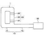
- the energy conversion device 1 includes a piping unit 10, an input unit 20, and an output unit 30.
- the piping part 10 is a hollow cylindrical member and constitutes a sealed space.
- the piping part 10 of this embodiment has a loop-shaped loop piping part 11 on one end side and a linear straight piping part 12 on the other end side.
- the piping unit 10 has an internal space filled with a medium.
- the piping part 10 can transmit acoustic energy through a medium.
- the medium includes a non-condensable medium and a condensable medium.
- the non-condensable medium is a fluid that does not change in gas-liquid phase in the operating temperature range of the energy conversion device 1
- the condensable medium is a fluid that changes in gas-liquid phase in the operating temperature range of the energy conversion device 1.
- air is used as the non-condensable medium
- water is used as the condensable medium.
- the input unit 20 is provided in the loop piping unit 11.
- the input unit 20 can convert heat energy input from the outside into acoustic energy.
- the input unit 20 includes a high temperature heat exchange unit 21, a low temperature heat exchange unit 22, and a regeneration unit 23. These are arranged coaxially along the axial direction of the loop piping portion 11.
- the high temperature heat exchange unit 21 is disposed on one end side of the regeneration unit 23, and the low temperature heat exchange unit 22 is disposed on the other end side of the regeneration unit 23. These heat exchange units 21 and 22 are in thermal contact with the regeneration unit 23.
- the high-temperature heat exchange unit 21 can input heat energy from the outside.
- the exhaust heat of the internal combustion engine can be used as heat energy by circulating the cooling water of the internal combustion engine through the high-temperature heat exchange unit 21. Thereby, the temperature of the one end side of the reproduction
- the low-temperature heat exchange unit 22 can exchange heat with the outside air.
- the temperature on the other end side of the reproducing unit 23 can be set to around room temperature.
- the other end side of the reproducing unit 23 can be made lower in temperature than the one end side, and a temperature gradient can be formed in the reproducing unit 23.
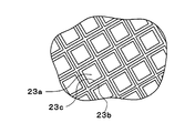
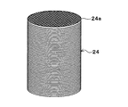
- the reproducing unit 23 is configured as a stack in which a large number of pores are formed. As shown in FIG. 3, the reproducing unit 23 of the present embodiment is configured as a honeycomb structure in which medium flow paths 23a through which a medium can flow are provided in parallel. The medium flow path 23a is partitioned by the wall part 23b. Further, it is desirable that the reproducing unit 23 uses a material having a low heat transfer coefficient in the medium flow direction in order to easily form a temperature gradient in the medium flow direction. In the present embodiment, a ceramic honeycomb that is a ceramic porous body is used as the reproducing unit 23.
- a temperature gradient is formed in the flow direction of the medium, so that the medium existing in the medium flow path 23a is compressed, heated, expanded, and cooled, and a sound wave that is thermoacoustic self-excited vibration is generated. . That is, in the reproducing unit 23, conversion from thermal energy to acoustic energy is performed. The acoustic energy generated by the input unit 20 is transmitted to the output unit 30.
- the output unit 30 can convert the acoustic energy generated by the input unit 20 into different types of energy, and output the converted energy to the outside.
- the output unit 30 may be provided with a piston that can reciprocate by acoustic energy, and the acoustic energy may be converted into kinetic energy and output.
- the output unit 30 may be provided with a linear generator having a piston that can reciprocate by acoustic energy, and the acoustic energy may be converted into electrical energy and output.
- the input unit 20 converts thermal energy into acoustic energy
- the output unit 30 converts the acoustic energy back into thermal energy, and outputs cold energy. You may make it do.
- the output unit 30 is configured as a heat pump, a high temperature heat exchange unit, a low temperature heat exchange unit, and a regeneration unit (stack) similar to those of the input unit 20 may be provided.
- the condensable medium contained in the medium undergoes a gas-liquid phase change. That is, the condensable medium evaporates when the medium is heated, and the condensable medium condenses when the medium is cooled. As a result, the volume change when the medium is heated and cooled can be increased, and the generated acoustic energy can be increased.
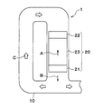
- the condensable medium is vaporized on the side close to the high temperature heat exchanger 21 in the regeneration unit 23. As shown in FIG. 2, the vaporized condensable medium can flow in a direction A that approaches the low-temperature heat exchange unit 22 inside the regeneration unit 23 and a direction B that diffuses outside the regeneration unit 23.
- the condensable medium flowing in the direction A is used for conversion from thermal energy to acoustic energy inside the reproduction unit 23.
- a part of the condensable medium flowing in the direction B may be condensed on the inner wall surface of the pipe 10.
- the condensable medium in the reproducing unit 23 is reduced, and the volume change when the medium is heated and cooled is reduced. As a result, energy loss occurs when conversion from thermal energy to acoustic energy is performed in the reproduction unit 23.
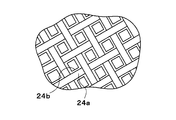
- a medium holding member 23 c is provided in the medium flow path 23 a of the reproducing unit 23.
- the medium holding member 23c is carried on the surface of the wall portion 23b as a base material.
- the medium holding member 23c is made of a material that can hold the condensable medium by interaction such as adsorption and absorption, and can release the held condensable medium. Adsorption and absorption may be performed by a chemical reaction, or may be performed using the structure of the medium holding material 23c.
- an inorganic moisture absorbent When water is used as the condensable medium as in the present embodiment, an inorganic moisture absorbent, an organic moisture absorbent, a metal organic structure (MOF), or the like can be used as the medium holding material 23c.
- the inorganic hygroscopic material include metal halides (CaCl 2 , LiCl, CaBr 2 , LiBr, etc.), metal hydroxides (LiOH), zeolite (hasley), and the like.
- the organic hygroscopic material include a water-absorbing polymer (polyacrylic acid).
- calcium chloride is used as the medium holding material 23c. Calcium chloride absorbs water and forms a hydrate.
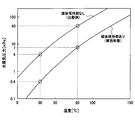
- FIG. 5 shows the vapor pressure of the condensable medium of this embodiment in which the medium holding material 23c is provided and the vapor pressure of the condensable medium of the comparative example in which the medium holding material 23c is not provided.
- the vapor pressure of the condensable medium in the medium flow path 23 a can be reduced by providing the reproducing unit 23 with the medium holding material 23 c.
- the vapor pressure of the condensable medium in the medium flow path 23 a is reduced from 40 kPa to 7 kPa by providing the medium holding member 23 c in the reproducing unit 23. Further, at 30 ° C., the vapor pressure of the condensable medium in the medium flow path 23a is reduced from 4 kPa to 0.4 kPa by providing the medium holding member 23c in the reproducing unit 23.
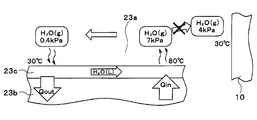
- FIG. 6A and 6B show the moving state of the condensable medium in the reproducing unit 23.
- FIG. 6A shows this embodiment in which the medium holding material 23c is provided
- FIG. 6B shows a comparative example in which the medium holding material 23c is not provided.
- the right side in the drawing is a high temperature side close to the high temperature heat exchange unit 21
- the left side in the drawing is a low temperature side close to the low temperature heat exchange unit 22.
- 6A and 6B in the medium flow path 23a, the temperature on the high temperature side is 80 ° C.
- the temperature on the low temperature side is 30 ° C.
- the temperature of the piping part 10 is set to 30 ° C. which is the same as the low temperature side of the medium flow path 23a.
- the comparative example shown in FIG. 6B will be described.
- the vapor pressure of the condensable medium in the low temperature side of the medium flow path 23a and the piping unit 10 is the same 4 kPa.
- the condensable medium vaporized on the high temperature side of the medium flow path 23a moves to both the low temperature side of the medium flow path 23a and the piping section 10.
- the gas phase condensable medium that has moved to the pipe unit 10 is condensed on the inner wall surface of the pipe unit 10 to form droplets W.
- the present embodiment shown in FIG. 6A will be described.
- the vapor pressure of the condensable medium in the pipe portion 10 is 4 kPa
- the vapor pressure of the condensable medium on the low temperature side of the medium flow path 23a is 0.4 kPa. It has become. For this reason, the condensable medium vaporized on the high temperature side of the medium flow path 23a moves preferentially to the low temperature side of the medium flow path 23a whose vapor pressure is lower than that of the pipe portion 10.
- the degree of absorption of the condensable medium by the medium holding material 23c becomes larger on the low temperature side than on the high temperature side of the medium flow path 23a. For this reason, a concentration gradient in which the concentration of the condensable medium decreases from the low temperature side toward the high temperature side occurs in the medium holding material 23c. Using this concentration gradient as a driving force, the condensable medium can move from the low temperature side to the high temperature side inside the medium holding material 23c.
- the condensable medium vaporized on the high temperature side of the medium flow path 23a moves to the low temperature side and is absorbed by the medium holding material 23c, and the condensable medium moves from the low temperature side to the high temperature side inside the medium holding material 23c.
- a cycle in which the condensable medium circulates is formed inside the reproduction unit 23, it is possible to avoid uneven distribution of the condensable medium inside the reproduction unit 23.
- the condensable medium Even if the condensable medium is condensed in the piping unit 10 during the operation of the energy conversion device 1, the condensable medium enters the medium flow path 23 a having a lower vapor pressure than the piping unit 10 while the energy conversion device 1 is stopped. Moving. For this reason, the condensable medium condensed in the piping part 10 can be collected again in the reproducing part 23.
- the condensable medium vaporized in the regenerator 23 moves to the pipe unit 10 by providing the medium holding material 23c capable of holding the condensable medium in the medium flow path 23a of the regenerator 23. Can be suppressed. Thereby, the energy loss by a condensable medium condensing in the piping part 10 can be suppressed as much as possible.
- the regeneration unit 23 is configured as a honeycomb structure, but the present invention is not limited thereto, and the regeneration unit may be configured differently.
- the reproducing unit 24 is a mesh laminate in which a plurality of mesh bodies 24a are laminated.
- a metal mesh can be used for the mesh body 24a.
- a medium holding material 24b is supported on a mesh-like mesh body 24a as a base material.
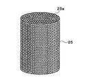
- the regeneration unit 25 is a pellet aggregate in which a large number of pellets 25a are aggregated.
- the pellet 25a is configured by supporting a medium holding material on particles as a base material.
- the pellet 25a can be made into an aggregate by filling a container, for example.
- the reproducing units 23, 24, and 25 carry the medium holding material as a separate member.
- the present invention is not limited to this, and the reproducing unit itself may be configured by the medium holding material.
- the medium holding material may be formed into a honeycomb structure, the medium holding material may be formed into a mesh, and these may be laminated to form a mesh laminated body, or the medium holding material may be formed into a pellet, May be formed into a pellet aggregate.
- air is used as the non-condensable medium.
- the present invention is not limited to this, and helium, nitrogen, argon, or the like may be used.
- water is used as the condensable medium.
- the present invention is not limited to this, and a different type of condensable medium may be used.
- the piping unit 10 is configured by the loop piping unit 11 and the straight piping unit 12.
- the present invention is not limited thereto, and the entire piping unit 10 may be configured in a straight line. May be configured in a loop shape, or may be configured such that a loop piping portion is provided at both ends of the straight piping portion.
- a single input unit 20 is provided.
- the present invention is not limited to this, and a plurality of input units 20 are arranged in series, and acoustic energy is amplified by the plurality of input units 20. You may make it do.
Landscapes
- Engineering & Computer Science (AREA)
- Chemical & Material Sciences (AREA)
- Combustion & Propulsion (AREA)
- Mechanical Engineering (AREA)
- General Engineering & Computer Science (AREA)
- Physics & Mathematics (AREA)
- Thermal Sciences (AREA)
- Dispersion Chemistry (AREA)
- Heat-Exchange Devices With Radiators And Conduit Assemblies (AREA)
- Cooling Or The Like Of Electrical Apparatus (AREA)
Abstract
An energy conversion device equipped with a conduit unit (10), an input unit (20), and an output unit (30). The conduit unit is filled with a medium capable of undergoing a gas-liquid phase change, and is able to transmit acoustic energy by means of the medium. The input unit is provided in the conduit unit, is able to receive an input of heat energy, and converts the heat energy to acoustic energy. The output unit is provided in the conduit unit and converts the acoustic energy to another type of energy. The input unit is provided with regeneration units (23, 24, and 25) that are capable of exhibiting a temperature gradient on the basis of the input of heat energy, and that cause the medium to change to a gas phase and a liquid phase on the basis of the temperature gradient. The regeneration units are provided with medium retention members (23c, 24b) that are able to retain and discharge the medium.
Description
本出願は、2016年9月20日に出願された日本出願番号2016-182480号に基づくもので、ここにその記載内容を援用する。
This application is based on Japanese Application No. 2016-182480 filed on September 20, 2016, the contents of which are incorporated herein by reference.
本開示は、熱エネルギーと音響エネルギーの間でエネルギー変換を行うエネルギー変換装置に関する。
The present disclosure relates to an energy conversion device that performs energy conversion between thermal energy and acoustic energy.
従来より、熱音響現象を利用して熱エネルギーと音響エネルギーの間でエネルギー変換を行うエネルギー変換装置が知られている。エネルギー変換装置は、密閉された配管の内部に設けられたスタックと、スタックの一端側に設けられた低温熱交換器と、スタックの他端側に設けられた高温熱交換器とを備え、スタックの両端に温度勾配を形成することで、熱音響自励振動である音波が発生する。
Conventionally, energy conversion devices that perform energy conversion between thermal energy and acoustic energy using a thermoacoustic phenomenon are known. The energy conversion device includes a stack provided inside a sealed pipe, a low-temperature heat exchanger provided on one end side of the stack, and a high-temperature heat exchanger provided on the other end side of the stack. By forming a temperature gradient at both ends, a sound wave that is thermoacoustic self-excited vibration is generated.
このようなエネルギー変換装置において、特許文献1では、エネルギー変換効率を向上させるために、非凝縮性媒体と凝縮性媒体の混合物を用いることが提案されている。
In such an energy conversion device, Patent Document 1 proposes to use a mixture of a non-condensable medium and a condensable medium in order to improve energy conversion efficiency.
しかしながら、上記従来技術の構成では、スタックの低温側と配管の温度が同程度であることが多く、スタックの高温側で気化した凝縮性媒体の一部が配管表面で凝縮することがある。このような配管表面での媒体の凝縮はエネルギー損失を招き、エネルギー変換装置のエネルギー収支を悪化させることとなる。
However, in the configuration of the above prior art, the temperature of the low temperature side of the stack and the temperature of the pipe are often the same, and a part of the condensable medium vaporized on the high temperature side of the stack may condense on the pipe surface. Such condensation of the medium on the pipe surface causes an energy loss and deteriorates the energy balance of the energy conversion device.
本開示は、エネルギー変換効率を向上させた、気液相変化可能な媒体を用いるエネルギー変換装置を提供することを目的とする。
This disclosure aims to provide an energy conversion device using a gas-liquid phase change medium with improved energy conversion efficiency.
本開示の第一の態様によれば、エネルギー変換装置は、配管部と、入力部と、出力部と、を備える。配管部は、気液相変化可能な媒体が充填され、媒体によって音響エネルギーを伝達可能である。入力部は、配管部に設けられ、熱エネルギーの入力が可能であり、熱エネルギーを音響エネルギーに変換する。出力部は、配管部に設けられ、音響エネルギーを異なる種類のエネルギーに変換する。
According to the first aspect of the present disclosure, the energy conversion device includes a piping unit, an input unit, and an output unit. The pipe portion is filled with a medium capable of changing the gas-liquid phase, and can transmit acoustic energy through the medium. An input part is provided in a piping part, can input heat energy, and converts heat energy into acoustic energy. The output unit is provided in the piping unit and converts acoustic energy into different types of energy.
入力部には、熱エネルギーの入力に基づいて温度勾配を発現可能であり、温度勾配に基づき媒体を気相および液相に変化させる再生部が設けられる。再生部には、媒体を保持および放出可能な媒体保持材が設けられている。
The input unit is provided with a regeneration unit that can develop a temperature gradient based on the input of thermal energy and changes the medium into a gas phase and a liquid phase based on the temperature gradient. The reproducing unit is provided with a medium holding material capable of holding and releasing the medium.
これにより、再生部の高温側で気化した媒体は、配管部よりも再生部の低温側に優先的に移動する。このため、再生部で気化した媒体が配管部に移動することを抑制でき、凝縮性媒体が配管部で凝縮することによるエネルギー損失を極力抑制することができる。
Thus, the medium vaporized on the high temperature side of the reproduction unit moves preferentially to the low temperature side of the reproduction unit rather than the piping unit. For this reason, it can suppress that the medium vaporized in the reproduction | regeneration part moves to a piping part, and can suppress the energy loss by condensing a condensable medium in a piping part as much as possible.
本開示についての上記目的およびその他の目的、特徴や利点は、添付の図面を参照しながら下記の詳細な記述により、より明確になる。図面において、
エネルギー変換装置の構成を示す図である。
ループ配管部および入力部を示す図である。
再生部の斜視図である。
図3の再生部の端面を部分的に拡大した図である。
凝縮性媒体の蒸気圧を示すグラフである。
実施形態における、再生部での凝縮性媒体の移動を示す図である。
比較例における、再生部での凝縮性媒体の移動を示す図である。
再生部の変形例を示す斜視図である。
図7の再生部の端面を部分的に拡大した図である。
再生部の変形例を示す斜視図である。
The above and other objects, features and advantages of the present disclosure will become more apparent from the following detailed description with reference to the accompanying drawings. In the drawing
It is a figure which shows the structure of an energy converter. It is a figure which shows a loop piping part and an input part. It is a perspective view of a reproducing part. FIG. 4 is a partially enlarged view of an end surface of the reproduction unit in FIG. 3. It is a graph which shows the vapor pressure of a condensable medium. It is a figure which shows the movement of the condensable medium in the reproducing | regenerating part in embodiment. It is a figure which shows the movement of the condensable medium in the reproducing | regenerating part in a comparative example. It is a perspective view which shows the modification of a reproducing part. It is the figure which expanded the end surface of the reproducing part of FIG. 7 partially. It is a perspective view which shows the modification of a reproducing part.
以下、本開示の実施形態について図1~図6Bに基づいて説明する。
Hereinafter, embodiments of the present disclosure will be described with reference to FIGS. 1 to 6B.
図1に示すように、エネルギー変換装置1は、配管部10、入力部20、出力部30を備えている。
As shown in FIG. 1, the energy conversion device 1 includes a piping unit 10, an input unit 20, and an output unit 30.
配管部10は、中空状の筒状部材であり、密閉空間を構成している。本実施形態の配管部10は、一端側がループ状のループ配管部11となっており、他端側が直線状の直線配管部12となっている。
The piping part 10 is a hollow cylindrical member and constitutes a sealed space. The piping part 10 of this embodiment has a loop-shaped loop piping part 11 on one end side and a linear straight piping part 12 on the other end side.
配管部10は、内部空間に媒体が充填されている。配管部10は、媒体を介して音響エネルギーを伝達可能となっている。
The piping unit 10 has an internal space filled with a medium. The piping part 10 can transmit acoustic energy through a medium.
媒体には、非凝縮性媒体と凝縮性媒体とが含まれている。非凝縮性媒体は、エネルギー変換装置1の作動温度範囲で気液相変化しない流体であり、凝縮性媒体は、エネルギー変換装置1の作動温度範囲で気液相変化する流体である。本実施形態では、非凝縮性媒体として空気を用い、凝縮性媒体として水を用いている。
The medium includes a non-condensable medium and a condensable medium. The non-condensable medium is a fluid that does not change in gas-liquid phase in the operating temperature range of the energy conversion device 1, and the condensable medium is a fluid that changes in gas-liquid phase in the operating temperature range of the energy conversion device 1. In this embodiment, air is used as the non-condensable medium, and water is used as the condensable medium.
入力部20は、ループ配管部11に設けられている。入力部20は、外部から入力された熱エネルギーを音響エネルギーに変換可能となっている。入力部20は、高温熱交換部21、低温熱交換部22、再生部23を備えている。これらは、ループ配管部11の軸方向に沿って同軸的に配置されている。
The input unit 20 is provided in the loop piping unit 11. The input unit 20 can convert heat energy input from the outside into acoustic energy. The input unit 20 includes a high temperature heat exchange unit 21, a low temperature heat exchange unit 22, and a regeneration unit 23. These are arranged coaxially along the axial direction of the loop piping portion 11.
高温熱交換部21は再生部23の一端側に配置され、低温熱交換部22は再生部23の他端側に配置されている。これらの熱交換部21、22は、再生部23と熱的に接触している。
The high temperature heat exchange unit 21 is disposed on one end side of the regeneration unit 23, and the low temperature heat exchange unit 22 is disposed on the other end side of the regeneration unit 23. These heat exchange units 21 and 22 are in thermal contact with the regeneration unit 23.
高温熱交換部21は、外部から熱エネルギーが入力可能となっている。例えば、高温熱交換部21に内燃機関の冷却水が循環するようにすることで、熱エネルギーとして内燃機関の排熱を利用することができる。これにより、再生部23の一端側の温度を高温にすることができる。
The high-temperature heat exchange unit 21 can input heat energy from the outside. For example, the exhaust heat of the internal combustion engine can be used as heat energy by circulating the cooling water of the internal combustion engine through the high-temperature heat exchange unit 21. Thereby, the temperature of the one end side of the reproduction | regeneration part 23 can be made high temperature.
低温熱交換部22は、外気と熱交換可能となっている。これにより、再生部23の他端側の温度を常温付近にすることができる。これにより、再生部23の他端側を一端側よりもよりも低温にすることができ、再生部23に温度勾配を形成することができる。
The low-temperature heat exchange unit 22 can exchange heat with the outside air. As a result, the temperature on the other end side of the reproducing unit 23 can be set to around room temperature. Thereby, the other end side of the reproducing unit 23 can be made lower in temperature than the one end side, and a temperature gradient can be formed in the reproducing unit 23.
再生部23は、多数の細孔が形成されたスタックとして構成されている。図3に示すように、本実施形態の再生部23は、媒体が流通可能な媒体流路23aが並列して設けられたハニカム構造体として構成されている。媒体流路23aは、壁部23bによって仕切られている。また、再生部23は、媒体の流通方向の温度勾配を形成しやすくするために、媒体の流通方向における熱伝達率が低い材料を用いることが望ましい。本実施形態では、再生部23としてセラミックス多孔体であるセラミックスハニカムを用いている。
The reproducing unit 23 is configured as a stack in which a large number of pores are formed. As shown in FIG. 3, the reproducing unit 23 of the present embodiment is configured as a honeycomb structure in which medium flow paths 23a through which a medium can flow are provided in parallel. The medium flow path 23a is partitioned by the wall part 23b. Further, it is desirable that the reproducing unit 23 uses a material having a low heat transfer coefficient in the medium flow direction in order to easily form a temperature gradient in the medium flow direction. In the present embodiment, a ceramic honeycomb that is a ceramic porous body is used as the reproducing unit 23.
再生部23では、媒体の流通方向に温度勾配が形成されることで、媒体流路23aに存在する媒体の圧縮、加熱、膨張、冷却が行われ、熱音響自励振動である音波が発生する。つまり、再生部23では、熱エネルギーから音響エネルギーへの変換が行われる。入力部20で生成した音響エネルギーは、出力部30に伝達される。
In the reproducing unit 23, a temperature gradient is formed in the flow direction of the medium, so that the medium existing in the medium flow path 23a is compressed, heated, expanded, and cooled, and a sound wave that is thermoacoustic self-excited vibration is generated. . That is, in the reproducing unit 23, conversion from thermal energy to acoustic energy is performed. The acoustic energy generated by the input unit 20 is transmitted to the output unit 30.
出力部30では、入力部20で生成した音響エネルギーを異なる種類のエネルギーに変換し、変換された後のエネルギーを外部に出力可能となっている。例えば、出力部30に音響エネルギーによって往復運動可能なピストンを設け、音響エネルギーを運動エネルギーに変換して出力してもよい。
The output unit 30 can convert the acoustic energy generated by the input unit 20 into different types of energy, and output the converted energy to the outside. For example, the output unit 30 may be provided with a piston that can reciprocate by acoustic energy, and the acoustic energy may be converted into kinetic energy and output.
あるいは、出力部30に音響エネルギーによって往復運動可能なピストンを備えるリニア発電機を設け、音響エネルギーを電気エネルギーに変換して出力してもよい。
Alternatively, the output unit 30 may be provided with a linear generator having a piston that can reciprocate by acoustic energy, and the acoustic energy may be converted into electrical energy and output.
あるいは、入力部20をプライムムーバーとし、出力部30をヒートポンプとすることで、入力部20で熱エネルギーを音響エネルギーに変換し、出力部30で音響エネルギーを熱エネルギーに再変換し、冷熱を出力するようにしてもよい。出力部30をヒートポンプとして構成する場合には、入力部20と同様の高温熱交換部、低温熱交換部、再生部(スタック)を設ければよい。
Alternatively, by using the input unit 20 as a prime mover and the output unit 30 as a heat pump, the input unit 20 converts thermal energy into acoustic energy, the output unit 30 converts the acoustic energy back into thermal energy, and outputs cold energy. You may make it do. When the output unit 30 is configured as a heat pump, a high temperature heat exchange unit, a low temperature heat exchange unit, and a regeneration unit (stack) similar to those of the input unit 20 may be provided.
次に、入力部20における凝縮性媒体の作用について説明する。再生部23で媒体が加熱および冷却される際に、媒体に含まれる凝縮性媒体は気液相変化する。つまり、媒体の加熱時に凝縮性媒体は蒸発し、媒体の冷却時に凝縮性媒体は凝縮する。この結果、媒体が加熱および冷却される際の体積変化を大きくすることができ、発生する音響エネルギーを大きくすることができる。
Next, the operation of the condensable medium in the input unit 20 will be described. When the medium is heated and cooled in the reproducing unit 23, the condensable medium contained in the medium undergoes a gas-liquid phase change. That is, the condensable medium evaporates when the medium is heated, and the condensable medium condenses when the medium is cooled. As a result, the volume change when the medium is heated and cooled can be increased, and the generated acoustic energy can be increased.
凝縮性媒体は、再生部23における高温熱交換器21に近い側で気化する。図2に示すように、気化した凝縮性媒体は、再生部23の内部で低温熱交換部22に近づく方向Aと、再生部23の外部に拡散する方向Bに流れることができる。
The condensable medium is vaporized on the side close to the high temperature heat exchanger 21 in the regeneration unit 23. As shown in FIG. 2, the vaporized condensable medium can flow in a direction A that approaches the low-temperature heat exchange unit 22 inside the regeneration unit 23 and a direction B that diffuses outside the regeneration unit 23.
方向Aに流れる凝縮性媒体は、再生部23の内部で熱エネルギーから音響エネルギーへの変換に用いられる。一方、方向Bに流れる凝縮性媒体は、一部が配管10の内壁面で凝縮することがある。この場合、再生部23における凝縮性媒体が減少し、媒体が加熱および冷却される際の体積変化が小さくなる。この結果、再生部23で熱エネルギーから音響エネルギーへの変換が行われる際に、エネルギー損失が発生する。
The condensable medium flowing in the direction A is used for conversion from thermal energy to acoustic energy inside the reproduction unit 23. On the other hand, a part of the condensable medium flowing in the direction B may be condensed on the inner wall surface of the pipe 10. In this case, the condensable medium in the reproducing unit 23 is reduced, and the volume change when the medium is heated and cooled is reduced. As a result, energy loss occurs when conversion from thermal energy to acoustic energy is performed in the reproduction unit 23.
そこで、本実施形態では、図4に示すように、再生部23の媒体流路23aに媒体保持材23cが設けられている。媒体保持材23cは、基材としての壁部23bの表面に担持されている。
Therefore, in the present embodiment, as shown in FIG. 4, a medium holding member 23 c is provided in the medium flow path 23 a of the reproducing unit 23. The medium holding member 23c is carried on the surface of the wall portion 23b as a base material.
媒体保持材23cは、吸着、吸収といった相互作用によって凝縮性媒体を保持することができ、保持した凝縮性媒体を放出することができる材料によって構成されている。吸着、吸収は、化学的な反応によって行われるものでもよく、媒体保持材23cの構造を利用して行われるものでもよい。
The medium holding member 23c is made of a material that can hold the condensable medium by interaction such as adsorption and absorption, and can release the held condensable medium. Adsorption and absorption may be performed by a chemical reaction, or may be performed using the structure of the medium holding material 23c.
本実施形態のように凝縮性媒体として水が用いられる場合には、媒体保持材23cとして無機系吸湿剤、有機系吸湿材、金属有機構造体(MOF)等を用いることができる。無機系吸湿材としては、金属ハロゲン化物(CaCl2、LiCl、CaBr2、LiBr等)、金属水酸化物(LiOH)、ゼオライト系(ハスクレイ)等を例示できる。有機系吸湿材としては、吸水性高分子(ポリアクリル酸)等を例示できる。本実施形態では、媒体保持材23cとして塩化カルシウムを用いている。塩化カルシウムは、水を吸収して水和物を生成する。
When water is used as the condensable medium as in the present embodiment, an inorganic moisture absorbent, an organic moisture absorbent, a metal organic structure (MOF), or the like can be used as the medium holding material 23c. Examples of the inorganic hygroscopic material include metal halides (CaCl 2 , LiCl, CaBr 2 , LiBr, etc.), metal hydroxides (LiOH), zeolite (hasley), and the like. Examples of the organic hygroscopic material include a water-absorbing polymer (polyacrylic acid). In the present embodiment, calcium chloride is used as the medium holding material 23c. Calcium chloride absorbs water and forms a hydrate.
図5は、媒体保持材23cが設けられている本実施形態の凝縮性媒体の蒸気圧と、媒体保持材23cが設けられていない比較例の凝縮性媒体の蒸気圧を示している。図5に示すように、再生部23に媒体保持材23cを設けることで、媒体流路23aにおける凝縮性媒体の蒸気圧を低下させることができる。
FIG. 5 shows the vapor pressure of the condensable medium of this embodiment in which the medium holding material 23c is provided and the vapor pressure of the condensable medium of the comparative example in which the medium holding material 23c is not provided. As shown in FIG. 5, the vapor pressure of the condensable medium in the medium flow path 23 a can be reduced by providing the reproducing unit 23 with the medium holding material 23 c.
例えば、80℃においては、再生部23に媒体保持材23cを設けることで、媒体流路23aにおける凝縮性媒体の蒸気圧が40kPaから7kPaに低下する。また、30℃においては、再生部23に媒体保持材23cを設けることで、媒体流路23aにおける凝縮性媒体の蒸気圧が4kPaから0.4kPaに低下する。
For example, at 80 ° C., the vapor pressure of the condensable medium in the medium flow path 23 a is reduced from 40 kPa to 7 kPa by providing the medium holding member 23 c in the reproducing unit 23. Further, at 30 ° C., the vapor pressure of the condensable medium in the medium flow path 23a is reduced from 4 kPa to 0.4 kPa by providing the medium holding member 23c in the reproducing unit 23.
図6Aおよび図6Bは、再生部23における凝縮性媒体の移動状態を示している。図6Aは媒体保持材23cが設けられている本実施形態を示し、図6Bは媒体保持材23cが設けられていない比較例を示している。図6Aおよび図6Bでは、図中右側が高温熱交換部21に近い高温側であり、図中左側が低温熱交換部22に近い低温側となっている。また、図6Aおよび図6Bでは、媒体流路23aにおいて、高温側の温度を80℃とし、低温側の温度を30℃としている。また、配管部10の温度を媒体流路23aの低温側と同じ30℃としている。
6A and 6B show the moving state of the condensable medium in the reproducing unit 23. FIG. 6A shows this embodiment in which the medium holding material 23c is provided, and FIG. 6B shows a comparative example in which the medium holding material 23c is not provided. 6A and 6B, the right side in the drawing is a high temperature side close to the high temperature heat exchange unit 21, and the left side in the drawing is a low temperature side close to the low temperature heat exchange unit 22. 6A and 6B, in the medium flow path 23a, the temperature on the high temperature side is 80 ° C., and the temperature on the low temperature side is 30 ° C. Moreover, the temperature of the piping part 10 is set to 30 ° C. which is the same as the low temperature side of the medium flow path 23a.
まず、図6Bに示す比較例について説明する。媒体保持材23cが設けられていない比較例では、媒体流路23aの低温側および配管部10における凝縮性媒体の蒸気圧は、同じ4kPaとなっている。このため、媒体流路23aの高温側で気化した凝縮性媒体は、媒体流路23aの低温側および配管部10の両方に移動する。配管部10に移動した気相の凝縮性媒体は、配管部10の内壁面で凝縮して液滴Wとなる。
First, the comparative example shown in FIG. 6B will be described. In the comparative example in which the medium holding member 23c is not provided, the vapor pressure of the condensable medium in the low temperature side of the medium flow path 23a and the piping unit 10 is the same 4 kPa. For this reason, the condensable medium vaporized on the high temperature side of the medium flow path 23a moves to both the low temperature side of the medium flow path 23a and the piping section 10. The gas phase condensable medium that has moved to the pipe unit 10 is condensed on the inner wall surface of the pipe unit 10 to form droplets W.
次に、図6Aに示す本実施形態について説明する。媒体保持材23cが設けられている本実施形態では、配管部10における凝縮性媒体の蒸気圧が4kPaであるのに対し、媒体流路23aの低温側における凝縮性媒体の蒸気圧が0.4kPaとなっている。このため、媒体流路23aの高温側で気化した凝縮性媒体は、配管部10よりも蒸気圧が低い媒体流路23aの低温側に優先的に移動する。
Next, the present embodiment shown in FIG. 6A will be described. In the present embodiment in which the medium holding member 23c is provided, the vapor pressure of the condensable medium in the pipe portion 10 is 4 kPa, whereas the vapor pressure of the condensable medium on the low temperature side of the medium flow path 23a is 0.4 kPa. It has become. For this reason, the condensable medium vaporized on the high temperature side of the medium flow path 23a moves preferentially to the low temperature side of the medium flow path 23a whose vapor pressure is lower than that of the pipe portion 10.
仮に気相の凝縮性媒体が配管部10側に移動したとしても、気相の凝縮性媒体は配管部10の内壁面で凝縮する前にループ配管部11を循環して媒体流路23の低温側に移動する(図2の矢印C)。この結果、凝縮性媒体が配管部10の内壁面で凝縮することを抑制できる。
Even if the gas phase condensable medium moves to the pipe part 10 side, the gas phase condensable medium circulates through the loop pipe part 11 before condensing on the inner wall surface of the pipe part 10, and the low temperature of the medium flow path 23. (Arrow C in FIG. 2). As a result, the condensable medium can be prevented from condensing on the inner wall surface of the pipe part 10.
また、エネルギー変換装置1の作動中には、媒体流路23aの高温側よりも低温側の方が媒体保持材23cによる凝縮性媒体の吸収度合が大きくなる。このため、媒体保持材23cの内部では、凝縮性媒体の濃度が低温側から高温側に向かって低くなる濃度勾配が生じる。この濃度勾配を駆動力として、媒体保持材23cの内部では、凝縮性媒体が低温側から高温側に移動することができる。
Further, during the operation of the energy conversion device 1, the degree of absorption of the condensable medium by the medium holding material 23c becomes larger on the low temperature side than on the high temperature side of the medium flow path 23a. For this reason, a concentration gradient in which the concentration of the condensable medium decreases from the low temperature side toward the high temperature side occurs in the medium holding material 23c. Using this concentration gradient as a driving force, the condensable medium can move from the low temperature side to the high temperature side inside the medium holding material 23c.
したがって、媒体流路23aの高温側で気化した凝縮性媒体が低温側に移動して媒体保持材23cに吸収され、媒体保持材23cの内部で凝縮性媒体が低温側から高温側に移動する。これにより、再生部23の内部で凝縮性媒体が循環するサイクルが形成されるため、再生部23内部で凝縮性媒体が偏在することを回避できる。
Therefore, the condensable medium vaporized on the high temperature side of the medium flow path 23a moves to the low temperature side and is absorbed by the medium holding material 23c, and the condensable medium moves from the low temperature side to the high temperature side inside the medium holding material 23c. Thereby, since a cycle in which the condensable medium circulates is formed inside the reproduction unit 23, it is possible to avoid uneven distribution of the condensable medium inside the reproduction unit 23.
また、仮にエネルギー変換装置1の作動中に配管部10で凝縮性媒体が凝縮したとしても、エネルギー変換装置1の停止中に凝縮性媒体は配管部10よりも蒸気圧が低い媒体流路23aに移動する。このため、配管部10で凝縮した凝縮性媒体を再生部23に再集結させることができる。
Even if the condensable medium is condensed in the piping unit 10 during the operation of the energy conversion device 1, the condensable medium enters the medium flow path 23 a having a lower vapor pressure than the piping unit 10 while the energy conversion device 1 is stopped. Moving. For this reason, the condensable medium condensed in the piping part 10 can be collected again in the reproducing part 23.
以上説明した本実施形態によれば、再生部23の媒体流路23aに凝縮性媒体を保持可能な媒体保持材23cを設けることで、再生部23で気化した凝縮性媒体が配管部10に移動することを抑制できる。これにより、凝縮性媒体が配管部10で凝縮することによるエネルギー損失を極力抑制することができる。
According to the present embodiment described above, the condensable medium vaporized in the regenerator 23 moves to the pipe unit 10 by providing the medium holding material 23c capable of holding the condensable medium in the medium flow path 23a of the regenerator 23. Can be suppressed. Thereby, the energy loss by a condensable medium condensing in the piping part 10 can be suppressed as much as possible.
(他の実施形態)
本開示は上述の実施形態に限定されることなく、本開示の趣旨を逸脱しない範囲内で、以下のように種々変形可能である。 (Other embodiments)
The present disclosure is not limited to the above-described embodiment, and can be variously modified as follows without departing from the spirit of the present disclosure.
本開示は上述の実施形態に限定されることなく、本開示の趣旨を逸脱しない範囲内で、以下のように種々変形可能である。 (Other embodiments)
The present disclosure is not limited to the above-described embodiment, and can be variously modified as follows without departing from the spirit of the present disclosure.
(1)上記実施形態では、再生部23をハニカム構造体として構成したが、これに限らず、再生部を異なる構成としてもよい。
(1) In the above embodiment, the regeneration unit 23 is configured as a honeycomb structure, but the present invention is not limited thereto, and the regeneration unit may be configured differently.
図7、図8に示す構成では、再生部24を複数のメッシュ体24aが積層されたメッシュ積層体としている。メッシュ体24aは、例えば金属メッシュを用いることができる。図8に示すように、基材としての網目状のメッシュ体24aに媒体保持材24bが担持されている。メッシュ体24aを積層して再生部24を構成することで、媒体流れ方向における熱伝達率を低くすることでき、温度勾配を形成しやすい。
7 and 8, the reproducing unit 24 is a mesh laminate in which a plurality of mesh bodies 24a are laminated. For example, a metal mesh can be used for the mesh body 24a. As shown in FIG. 8, a medium holding material 24b is supported on a mesh-like mesh body 24a as a base material. By forming the reproducing unit 24 by laminating the mesh bodies 24a, the heat transfer coefficient in the medium flow direction can be lowered, and a temperature gradient is easily formed.
図9に示す構成では、再生部25を多数のペレット25aが集合したペレット集合体としている。ペレット25aは、基材としての粒子に媒体保持材を担持することで構成されている。ペレット25aは、例えば容器に充填することで集合体とすることができる。粒状のペレット25aによって再生部25を構成することで、媒体流れ方向における熱伝達率を低くすることでき、温度勾配を形成しやすい。
In the configuration shown in FIG. 9, the regeneration unit 25 is a pellet aggregate in which a large number of pellets 25a are aggregated. The pellet 25a is configured by supporting a medium holding material on particles as a base material. The pellet 25a can be made into an aggregate by filling a container, for example. By configuring the regeneration unit 25 with the granular pellets 25a, the heat transfer coefficient in the medium flow direction can be lowered, and a temperature gradient is easily formed.
(2)上記実施形態では、再生部23、24、25に別部材の媒体保持材を担持させるようにしたが、これに限らず、再生部そのものを媒体保持材によって構成してもよい。例えば、媒体保持材をハニカム構造体に成形してもよく、媒体保持材をメッシュに成形し、これらを積層してメッシュ積層体に成形してもよく、媒体保持材をペレットに成形し、これらを集合させてペレット集合体に成形してもよい。
(2) In the above embodiment, the reproducing units 23, 24, and 25 carry the medium holding material as a separate member. However, the present invention is not limited to this, and the reproducing unit itself may be configured by the medium holding material. For example, the medium holding material may be formed into a honeycomb structure, the medium holding material may be formed into a mesh, and these may be laminated to form a mesh laminated body, or the medium holding material may be formed into a pellet, May be formed into a pellet aggregate.
(3)上記実施形態では、非凝縮性媒体として空気を用いたが、これに限らず、ヘリウム、窒素、アルゴン等を用いてもよい。
(3) In the above embodiment, air is used as the non-condensable medium. However, the present invention is not limited to this, and helium, nitrogen, argon, or the like may be used.
(4)上記実施形態では、凝縮性媒体として水を用いたが、これに限らず、異なる種類の凝縮性媒体を用いてもよい。この場合、気化潜熱が大きい流体を用いることが望ましく、このような流体としてアルコール類、アンモニア等の分子間水素結合を有する流体を好適に用いることができる。
(4) In the above embodiment, water is used as the condensable medium. However, the present invention is not limited to this, and a different type of condensable medium may be used. In this case, it is desirable to use a fluid having a large latent heat of vaporization, and a fluid having intermolecular hydrogen bonds such as alcohols and ammonia can be suitably used as such a fluid.
(5)上記実施形態では、配管部10をループ配管部11と直線配管部12とから構成したが、これに限らず、配管部10全体を直線状に構成してもよく、配管部10全体をループ状に構成してもよく、あるいは直線配管部の両端にループ配管部が設けられた構成としてもよい。
(5) In the above-described embodiment, the piping unit 10 is configured by the loop piping unit 11 and the straight piping unit 12. However, the present invention is not limited thereto, and the entire piping unit 10 may be configured in a straight line. May be configured in a loop shape, or may be configured such that a loop piping portion is provided at both ends of the straight piping portion.
(6)上記実施形態では、1つの入力部20が設けられた構成としたが、これに限らず、複数の入力部20を直列的に配置し、複数の入力部20によって音響エネルギーが増幅されるようにしてもよい。
(6) In the above embodiment, a single input unit 20 is provided. However, the present invention is not limited to this, and a plurality of input units 20 are arranged in series, and acoustic energy is amplified by the plurality of input units 20. You may make it do.
本開示は、実施形態に準拠して記述されたが、本開示は当該実施形態や構造に限定されるものではないと理解される。本開示は、様々な変形例や均等範囲内の変形をも包含する。加えて、様々な組み合わせや形態、さらには、それらに一要素のみ、それ以上、あるいはそれ以下、を含む他の組み合わせや形態をも、本開示の範疇や思想範囲に入るものである。
Although the present disclosure has been described based on the embodiment, it is understood that the present disclosure is not limited to the embodiment or the structure. The present disclosure includes various modifications and modifications within the equivalent range. In addition, various combinations and forms, as well as other combinations and forms including only one element, more or less, are within the scope and spirit of the present disclosure.
Claims (6)
- 気液相変化可能な媒体が充填され、前記媒体によって音響エネルギーを伝達可能な配管部(10)と、
前記配管部に設けられ、熱エネルギーの入力が可能であり、前記熱エネルギーを前記音響エネルギーに変換する入力部(20)と、
前記配管部に設けられ、前記音響エネルギーを異なる種類のエネルギーに変換する出力部(30)とを備え、
前記入力部には、前記熱エネルギーの入力に基づいて温度勾配を発現可能であり、前記温度勾配に基づき前記媒体を気相および液相に変化させる再生部(23、24、25)が設けられ、
前記再生部には、前記媒体を保持および放出可能な媒体保持材(23c、24b)が設けられているエネルギー変換装置。 A pipe section (10) filled with a medium capable of changing a gas-liquid phase and capable of transmitting acoustic energy by the medium;
An input unit (20) that is provided in the piping unit and is capable of inputting thermal energy, and converts the thermal energy into the acoustic energy;
An output part (30) provided in the pipe part for converting the acoustic energy into a different kind of energy;
The input unit is provided with a regeneration unit (23, 24, 25) that can develop a temperature gradient based on the input of the thermal energy and changes the medium into a gas phase and a liquid phase based on the temperature gradient. ,
An energy conversion device in which the reproducing unit is provided with a medium holding material (23c, 24b) capable of holding and releasing the medium. - 前記再生部における前記媒体の蒸気圧は、前記配管部の前記媒体保持材が設けられていない部位における前記媒体の蒸気圧よりも低くなっている請求項1に記載のエネルギー変換装置。 The energy conversion device according to claim 1, wherein a vapor pressure of the medium in the regeneration unit is lower than a vapor pressure of the medium in a portion of the piping unit where the medium holding material is not provided.
- 前記再生部は、前記媒体保持材が担持された基材(23b、24a)を有しており、
前記基材は、前記媒体保持材と異なる材料から構成されている請求項1または2に記載のエネルギー変換装置。 The reproduction unit has a base material (23b, 24a) on which the medium holding material is carried,
The energy conversion device according to claim 1, wherein the base material is made of a material different from the medium holding material. - 前記再生部は、前記媒体保持材によって構成されている請求項1または2に記載のエネルギー変換装置。 The energy conversion device according to claim 1 or 2, wherein the reproducing unit is configured by the medium holding material.
- 前記媒体は水であり、前記媒体保持材は無機系吸湿材、有機系吸湿材または有機金属構造体のいずれかである請求項1ないし4のいずれか1つに記載のエネルギー変換装置。 The energy conversion device according to any one of claims 1 to 4, wherein the medium is water, and the medium holding material is any one of an inorganic moisture absorbent, an organic moisture absorbent, and an organometallic structure.
- 前記再生部は、ハニカム構造体(23)、メッシュ積層体(24)あるいはペレット集合体(25)のいずれかとして構成されている請求項1ないし5のいずれか1つに記載のエネルギー変換装置。 The energy conversion device according to any one of claims 1 to 5, wherein the regeneration unit is configured as any one of a honeycomb structure (23), a mesh laminate (24), and a pellet aggregate (25).
Applications Claiming Priority (2)
| Application Number | Priority Date | Filing Date | Title |
|---|---|---|---|
| JP2016-182480 | 2016-09-20 | ||
| JP2016182480A JP6574745B2 (en) | 2016-09-20 | 2016-09-20 | Energy converter |
Publications (1)
| Publication Number | Publication Date |
|---|---|
| WO2018056074A1 true WO2018056074A1 (en) | 2018-03-29 |
Family
ID=61689520
Family Applications (1)
| Application Number | Title | Priority Date | Filing Date |
|---|---|---|---|
| PCT/JP2017/032415 WO2018056074A1 (en) | 2016-09-20 | 2017-09-08 | Energy conversion device |
Country Status (2)
| Country | Link |
|---|---|
| JP (1) | JP6574745B2 (en) |
| WO (1) | WO2018056074A1 (en) |
Cited By (1)
| Publication number | Priority date | Publication date | Assignee | Title |
|---|---|---|---|---|
| CN109458315A (en) * | 2018-12-26 | 2019-03-12 | 浙江大学 | With the enclosed traveling wave thermoacoustic prime mover of gas-liquid phase transition |
Families Citing this family (4)
| Publication number | Priority date | Publication date | Assignee | Title |
|---|---|---|---|---|
| JP7032987B2 (en) * | 2018-04-24 | 2022-03-09 | 株式会社Soken | Thermoacoustic device |
| JP2019200015A (en) * | 2018-05-18 | 2019-11-21 | 株式会社Soken | Thermoacoustic device |
| JP7057224B2 (en) * | 2018-06-01 | 2022-04-19 | 株式会社Soken | Thermoacoustic device |
| JP2019210647A (en) * | 2018-06-01 | 2019-12-12 | 株式会社Soken | Water production apparatus |
Citations (5)
| Publication number | Priority date | Publication date | Assignee | Title |
|---|---|---|---|---|
| JP2000088378A (en) * | 1998-07-17 | 2000-03-31 | Idotai Tsushin Sentan Gijutsu Kenkyusho:Kk | Loop tube air pipe acoustic wave refrigerator |
| US20030101734A1 (en) * | 2001-12-04 | 2003-06-05 | University Of Mississippi | Thermoacoustic refrigeration device and method |
| JP2009074722A (en) * | 2007-09-19 | 2009-04-09 | Aisin Seiki Co Ltd | Phase change type thermoacoustic engine |
| JP2011099599A (en) * | 2009-11-05 | 2011-05-19 | Aisin Seiki Co Ltd | Heat transport pipe |
| JP2012237295A (en) * | 2011-05-13 | 2012-12-06 | Nippon Telegr & Teleph Corp <Ntt> | Stack for thermoacoustic device and method for manufacturing stack for thermoacoustic device |
-
2016
- 2016-09-20 JP JP2016182480A patent/JP6574745B2/en not_active Expired - Fee Related
-
2017
- 2017-09-08 WO PCT/JP2017/032415 patent/WO2018056074A1/en active Application Filing
Patent Citations (5)
| Publication number | Priority date | Publication date | Assignee | Title |
|---|---|---|---|---|
| JP2000088378A (en) * | 1998-07-17 | 2000-03-31 | Idotai Tsushin Sentan Gijutsu Kenkyusho:Kk | Loop tube air pipe acoustic wave refrigerator |
| US20030101734A1 (en) * | 2001-12-04 | 2003-06-05 | University Of Mississippi | Thermoacoustic refrigeration device and method |
| JP2009074722A (en) * | 2007-09-19 | 2009-04-09 | Aisin Seiki Co Ltd | Phase change type thermoacoustic engine |
| JP2011099599A (en) * | 2009-11-05 | 2011-05-19 | Aisin Seiki Co Ltd | Heat transport pipe |
| JP2012237295A (en) * | 2011-05-13 | 2012-12-06 | Nippon Telegr & Teleph Corp <Ntt> | Stack for thermoacoustic device and method for manufacturing stack for thermoacoustic device |
Non-Patent Citations (2)
| Title |
|---|
| SLATON, WILLIAM V.: "The effect of the physical properties of the tube wall on the attenuation of sound in evaporating and condensing gas- vapor mixtures", J. ACOUST. SOC. AM., vol. 108, no. 5, November 2000 (2000-11-01), pages 2120 - 2124, XP012001987 * |
| YUKIO TADA: "Sohenka o Riyo shita Netsuonkyo Engine ni Okeru Onpa Hassei Kiko", DAI 52 KAI NATIONAL HEAT TRANSFER SYMPOSIUM OF JAPAN KOEN RONBUNSHU( CD-ROM, vol. 52, June 2015 (2015-06-01) * |
Cited By (1)
| Publication number | Priority date | Publication date | Assignee | Title |
|---|---|---|---|---|
| CN109458315A (en) * | 2018-12-26 | 2019-03-12 | 浙江大学 | With the enclosed traveling wave thermoacoustic prime mover of gas-liquid phase transition |
Also Published As
| Publication number | Publication date |
|---|---|
| JP2018048556A (en) | 2018-03-29 |
| JP6574745B2 (en) | 2019-09-11 |
Similar Documents
| Publication | Publication Date | Title |
|---|---|---|
| WO2018056074A1 (en) | Energy conversion device | |
| JP6369997B2 (en) | Electronics | |
| JP5077419B2 (en) | Chemical heat storage device | |
| JP2012211713A (en) | Chemical heat storage reactor, and chemical heat storage system | |
| JP5482681B2 (en) | Heat storage device | |
| JP4567996B2 (en) | Thermal storage heat pump system | |
| JP2006529022A (en) | Thermodynamic apparatus and method for heat absorption | |
| US8640489B2 (en) | Heat pump | |
| JP2013072558A (en) | Heat recovery type heating device | |
| JP2005024231A5 (en) | ||
| JP5917811B2 (en) | Heat transport device and heat exchange reactor | |
| JP2017218492A (en) | Chemical thermal storage material and heat storage container using chemical thermal storage material | |
| JP6372126B2 (en) | Heat transport equipment | |
| JP5453950B2 (en) | Thermoacoustic engine | |
| WO2019003961A1 (en) | Energy conversion system | |
| JP6036444B2 (en) | Adsorption heat pump | |
| JP2012172901A (en) | Chemical heat storage heat transfer device and heat exchanger type reactor | |
| JP6364198B2 (en) | Thermal storage reactor and thermal storage system | |
| Vasiliev et al. | The sorption heat pipe—a new device for thermal control and active cooling | |
| Çağlar | Design and experimental testing of an adsorbent bed for a thermal wave adsorption cooling cycle | |
| JP2018128190A (en) | Heat storage device | |
| JP2018146162A (en) | Heat storage system | |
| JP6400926B2 (en) | Heat storage system | |
| CA3177348A1 (en) | Sorption heat transformer and thermal storage | |
| Vasiliev et al. | Heat pipes− good tool for fuel cells thermal management |
Legal Events
| Date | Code | Title | Description |
|---|---|---|---|
| 121 | Ep: the epo has been informed by wipo that ep was designated in this application |
Ref document number: 17852851 Country of ref document: EP Kind code of ref document: A1 |
|
| NENP | Non-entry into the national phase |
Ref country code: DE |
|
| 122 | Ep: pct application non-entry in european phase |
Ref document number: 17852851 Country of ref document: EP Kind code of ref document: A1 |