WO2018055722A1 - Video projection lighting device - Google Patents
Video projection lighting device Download PDFInfo
- Publication number
- WO2018055722A1 WO2018055722A1 PCT/JP2016/077948 JP2016077948W WO2018055722A1 WO 2018055722 A1 WO2018055722 A1 WO 2018055722A1 JP 2016077948 W JP2016077948 W JP 2016077948W WO 2018055722 A1 WO2018055722 A1 WO 2018055722A1
- Authority
- WO
- WIPO (PCT)
- Prior art keywords
- light
- illumination
- video
- unit
- video projection
- Prior art date
Links
Images


Classifications
-
- H—ELECTRICITY
- H05—ELECTRIC TECHNIQUES NOT OTHERWISE PROVIDED FOR
- H05B—ELECTRIC HEATING; ELECTRIC LIGHT SOURCES NOT OTHERWISE PROVIDED FOR; CIRCUIT ARRANGEMENTS FOR ELECTRIC LIGHT SOURCES, IN GENERAL
- H05B47/00—Circuit arrangements for operating light sources in general, i.e. where the type of light source is not relevant
- H05B47/10—Controlling the light source
- H05B47/17—Operational modes, e.g. switching from manual to automatic mode or prohibiting specific operations
-
- F—MECHANICAL ENGINEERING; LIGHTING; HEATING; WEAPONS; BLASTING
- F21—LIGHTING
- F21S—NON-PORTABLE LIGHTING DEVICES; SYSTEMS THEREOF; VEHICLE LIGHTING DEVICES SPECIALLY ADAPTED FOR VEHICLE EXTERIORS
- F21S8/00—Lighting devices intended for fixed installation
- F21S8/04—Lighting devices intended for fixed installation intended only for mounting on a ceiling or the like overhead structures
-
- F—MECHANICAL ENGINEERING; LIGHTING; HEATING; WEAPONS; BLASTING
- F21—LIGHTING
- F21V—FUNCTIONAL FEATURES OR DETAILS OF LIGHTING DEVICES OR SYSTEMS THEREOF; STRUCTURAL COMBINATIONS OF LIGHTING DEVICES WITH OTHER ARTICLES, NOT OTHERWISE PROVIDED FOR
- F21V33/00—Structural combinations of lighting devices with other articles, not otherwise provided for
-
- H—ELECTRICITY
- H05—ELECTRIC TECHNIQUES NOT OTHERWISE PROVIDED FOR
- H05B—ELECTRIC HEATING; ELECTRIC LIGHT SOURCES NOT OTHERWISE PROVIDED FOR; CIRCUIT ARRANGEMENTS FOR ELECTRIC LIGHT SOURCES, IN GENERAL
- H05B47/00—Circuit arrangements for operating light sources in general, i.e. where the type of light source is not relevant
- H05B47/10—Controlling the light source
- H05B47/165—Controlling the light source following a pre-assigned programmed sequence; Logic control [LC]
Definitions
- the present invention relates to a video projection illumination device.
- Patent Document 1 discloses an endoscope configured such that illumination light transmitted through a lens is distributed so that the center is dark and the periphery is brightened in a ring shape.
- the illumination light emitted from the optical element illuminates the periphery of the visual field range in a ring shape, so that the visual field range such as the inner wall surface of the tube at the time of use is efficiently and preferentially illuminated.
- Japanese Patent Application Laid-Open No. 2004-228561 can enhance the sense of realism of an image displayed on the screen of the image display device by controlling the illumination of the viewing space in conjunction with the image displayed on the screen of the image display device.
- An illumination method and an illumination device are disclosed.
- the lighting device is virtualized from an image displayed on the image display device with at least one of the illumination level, light color, light distribution, and direction of the viewing space.
- One or more light sources provided in the viewing space are controlled so as to substantially match the corresponding parameters in the virtual image space.
- the optical element emits the illumination light received from the light guide from the emission end, but the brightness of the illumination light cannot be controlled for each region. Moreover, the emitted illumination light is not bright enough for general illumination.
- the image display device and the illumination device are configured separately. For this reason, the user needs to separately prepare an image display device and an illumination device suitable for the viewing space, and then adjust the image and the illumination light so that the sense of reality of the image is improved.
- the image quality may deteriorate due to insufficient adjustment of the image and the illumination light, such as when the image and the illumination light are overlapped only by integrating them.
- an object of the present invention is to provide a video projection illumination device that illuminates the periphery of a projection video while suppressing deterioration in image quality of the projection video.
- An image projection illumination apparatus emits a light beam of ambient illumination light that illuminates a second area surrounding a first area and a video projection unit that projects an image onto the first area. And an ambient lighting unit.
- FIG. 1 It is a figure which shows an example of a structure of the video projection illumination apparatus which concerns on Embodiment 1 of this invention. It is a block diagram which shows an example of the system configuration
- FIG. 1 is a diagram showing an example of the configuration of the video projection lighting apparatus according to Embodiment 1 of the present invention.
- FIG. 1A is a cross-sectional view of the video projection illumination device
- FIG. 1B is a plan view of the video projection illumination device viewed from the emission side.
- FIG. 2 is a block diagram showing an example of the system configuration of the video projection illumination apparatus according to Embodiment 1 of the present invention.
- FIG. 3 is a diagram showing an example of the configuration of the light source according to Embodiment 1 of the present invention.
- FIG. 3A is a plan view of the light source viewed from the emission side
- FIG. 3B is a cross-sectional view of the light source.
- FIG. 3A is a plan view of the light source viewed from the emission side
- FIG. 3B is a cross-sectional view of the light source.
- FIG. 4 is a diagram illustrating a usage state of the video projection illumination device according to the first embodiment of the present invention.
- FIG. 4A is a diagram showing a usage situation in a video playback mode to be described later.
- FIG. 4B is a diagram illustrating a usage situation in an illumination mode to be described later.
- the video projection illumination device 1 includes a light source substrate 51, a light source 5, a light distribution control unit 6, a video projection unit 7, a camera (imaging unit) 8, an environmental sensor 9, a housing 10, and the like. It has. Further, as shown in FIG. 2, for example, the video projection illumination device 1 includes a power source 107, an environment sensing unit 100, an operation input unit 101, a data storage unit 102, a video reception unit 103, a control unit 110, an ambient illumination unit 21, An illumination unit 22 and the like are provided.
- the control unit 110 includes an illumination video management unit 106, an illumination control unit 104, and a video control unit 105, as shown in FIG.
- the light source substrate 51 is made of a material having excellent heat dissipation, such as a metal substrate or a ceramic substrate.
- a light source 5 On the first main surface 51a of the light source substrate 51, for example, as shown in FIG. 1A, a light source 5, a circuit pattern (not shown) connected to the light source 5, and the like are provided.
- a circuit pattern may also be formed on the second main surface 51 b of the light source substrate 51. In this case, the circuit pattern of the first main surface 51a and the second main surface 51b are formed through through holes (not shown) penetrating the first main surface 51a and the second main surface 51b of the light source substrate 51.
- a circuit pattern may be connected. Electric power is supplied to the light source 5 from the power source 107 via the circuit pattern.
- a plurality of light sources 5 are arranged in an annular shape in plan view when viewed from the emission side.
- the plurality of light sources 5 have a double structure in which a plurality of light sources 5 are arranged along the respective circumferential directions of the inner periphery and the outer periphery.
- the light source 5 is arrange
- the light source 5 may be arranged in an elliptical ring shape, a rectangular ring shape, or the like. Further, the shape of the arrangement of the light sources 5 may be different between the inner peripheral side and the outer peripheral side.
- the light source 5 includes, for example, a base 5a, an LED (Light Emitting Diode) chip 5c, and a sealing body 5d as shown in FIG.
- the base 5 a has a rectangular shape in a plan view from the emission side and a U shape in a sectional view.
- the base 5a has an opening 5b, and the LED chip 5 is disposed in the opening 5b of the base 5a.
- the sealing body 5 covers the LED chip 5c and is provided so as to fill the space in the opening 5b of the base body 5a.
- the base 5a is made of a material having excellent heat dissipation, such as metal or ceramic.
- the sealing body 5d is made of, for example, a transparent resin.
- the shape of the base body 5a in a plan view is a rectangle, but other than this, for example, any shape such as a polygon excluding a rectangle, a circle, an ellipse, or the like may be used.
- the light source 5 is composed of, for example, an LED chip 5c that emits white light.
- the light source 5 may be composed of, for example, an LED chip 5c that emits blue light and a phosphor that is excited by receiving blue light and emits light having a spectral characteristic from green to red.
- white light is emitted from the light source 5 by overlapping the blue light and the light emitted from the phosphor.
- the phosphor is composed of, for example, a YAG (Yttrium Aluminum Garnet) phosphor.
- the phosphor is mixed with the sealing body 5d, for example.
- the light source 5 may be provided with optical components such as a lens and a reflector for adjusting the light distribution of the emitted light and improving the light extraction efficiency.
- optical components include a convex lens made of a light-transmitting material, a mirror made of metal vapor deposition, a reflector using total reflection, and the like.
- the convex lens may be constituted by, for example, a sealing body 5d constituting the light source 5, or may be separately provided on the emission side of the light source 5.
- a mirror may be comprised by metal-depositing the wall surface in the opening part 5b of the light source 5, for example.
- the reflector may be constituted by a reflector provided on a wall surface or the like in the opening 5 b of the light source 5.
- one LED chip 5c is provided for each light source 5, but a plurality of LED chips 5c may be provided for each light source 5.
- the LED chip 5c is divided into a plurality of parts in the light source 5, whereby the heat dissipation of the LED chip 5c is improved, and the light source 5 having an increased amount of light is provided.
- the plurality of LED chips 5c may be arranged symmetrically, for example, in a rectangular shape or a concentric shape with respect to the center of the light emitting surface of the light source 5. desirable.
- the area where the plurality of LED chips 5c are arranged can be collectively regarded as the light emitting area of the light source 5, and the plurality of LED chips 5c are arranged symmetrically, so that the design of optical components of the light source 5 is facilitated.
- the shape of the LED chip 5c is a rectangle in plan view, but other than this, for example, any shape such as a polygon, a circle, an ellipse, etc. excluding the rectangle may be used. Absent.
- the several light source 5 is divided
- the light sources 5 may be arranged for one row, or may be arranged for three or more rows.
- the light sources 5 When the light sources 5 are arranged for one row, for example, it is desirable that the light sources 5 that emit the luminous flux of the ambient illumination light 11 and the light sources 5 that emit the central illumination light 12 are alternately arranged. Specifically, it is desirable that the later-described light distribution control unit 6 is provided with alternately a later-described peripheral illumination light distribution control unit 6a and a central illumination light distribution control unit 6b illustrated in FIG. In this case, since the number of the light sources 5 can be reduced, the video projection illumination device 1 with reduced power consumption is provided. In addition, the video projection lighting device 1 that is small in size and easy to handle is provided.
- the shape of the light distribution control unit 6 may be adjusted so that the orientation control is different for each row or for each light source 5.
- the video projection illumination device 1 is provided in which a sufficient amount of light is obtained and the degree of freedom of light distribution control of the light emitted from the light sources 5 is improved.
- the light sources 5 are arranged concentrically in a plan view from the emission side, but in addition to this, the peripheral illumination light 11 such as a polygonal shape such as a rectangular shape, an elliptical shape, etc. You may change arbitrarily according to the condition of the area
- the light sources 5 are arranged densely.
- “densely arranged” means, for example, the peripheral illumination light 11 emitted from the adjacent light sources 5 in the video peripheral region (second region) 11a shown in FIGS. 4 (a) and 4 (b). It means that the light source 5 is arranged so that the ends of the two overlap.
- “densely arranged” means that the central illumination light emitted from the adjacent light sources 5 in the image peripheral area 11 a shown in FIGS. 4A and 4B. This means that the light source 5 is arranged so that the ends of 12 overlap.
- the illuminance distributions of the peripheral illumination light 11 emitted from the respective light sources 5 overlap each other little by little, so that uneven illuminance is suppressed and smooth illuminance is achieved in the video peripheral area 11a. Distribution is obtained.
- the central illumination light 12 if the light sources 5 are densely arranged, the illuminance distributions of the central illumination light 12 emitted from the respective light sources 5 overlap little by little. A smooth illuminance distribution is obtained at 12a.
- the light sources 5 when the light sources 5 are arranged in a plurality of rows, it is desirable that the light sources 5 in adjacent rows are arranged so as not to line up in a direction orthogonal to the rows. Specifically, it is desirable that the light sources 5 in adjacent rows are not arranged adjacent to each other but are alternately arranged along the columns. As a result, in the region where the illumination light emitted from the light sources 5 in the adjacent rows overlaps, the region illuminated mainly by the illumination light emitted from the light sources 5 in one row and the other mainly in the rows. The areas illuminated by the illumination light emitted from the light sources 5 in the rows appear alternately.
- the illuminance unevenness of the illuminance distribution due to the illumination light emitted from the light sources 5 arranged in one row, and the light emitted from the light sources 5 in the adjacent rows Since the illuminance unevenness of the illuminance distribution due to the illuminating light is canceled, high-quality illumination light is provided.
- the inner peripheral light source 5 and the outer peripheral light source 5 are arranged only in the radial direction, that is, in the linear direction extending from the center of the light source substrate 51, either the inner peripheral or the outer peripheral light source 5. It has come to be.
- the inner peripheral light source 5 and the outer peripheral light source 5 are alternately arranged.
- region 12a the area
- the light distribution control unit 6 is arranged to face the light source substrate 51 on the first main surface 51a side that is the emission side.
- the orientation control unit 6 includes a peripheral illumination orientation control unit 6a that controls the light distribution of the light source 5 on the outer peripheral side, and a central illumination light distribution control unit 6b that controls the light distribution of the light source 5 on the inner peripheral side.
- the light distribution control unit 6 is configured by integrating a peripheral illumination orientation control unit 6a and a central illumination orientation control unit 6b.
- the orientation control unit 6 is made of, for example, a resin having translucency such as polymethyl methacrylate resin (PMMA: Polymethyl Methacrylate), polycarbonate (PC: polycarbonate), or the like.
- an ambient illumination orientation control unit 6a corresponding to a plurality of light sources and a central illumination orientation control unit 6b are integrally molded by injection molding. Thereby, the orientation control unit 6 that is easy to assemble and has reduced manufacturing costs is provided.
- the outer peripheral light source 5 and the ambient illumination light distribution control unit 6a constitute an ambient illumination unit 21 shown in FIG.
- the inner peripheral light source 5 and the central illumination orientation control unit 6b constitute a central illumination unit 22 shown in FIG.
- the ambient illumination orientation control unit 6 a of the ambient illumination unit 21 has a surface facing the light source 5, that is, a light incident surface 6 c that is flat, and a surface opposite to the light source 5. That is, the light exit surface 6d is formed of a convex lens protruding in the light exit direction.
- the ambient illumination light distribution control unit 6a suppresses the divergence of the light beam emitted from the light source 5, and emits the light beam emitted from the light source 5 so as not to overlap a video projection region (first region) 12a described later. It is configured to be oriented outward.
- FIG. 5 is a cross-sectional view of the ambient illumination unit according to Embodiment 1 of the present invention.
- the divergence angle of the luminous flux emitted from the outer light source 5 is suppressed by the peripheral illumination light distribution control unit 6 a of the light distribution control unit 6.
- the ambient illumination light distribution control unit 6 a is arranged so that its optical axis is located on the opposite side of the image projection unit 7 with respect to the optical axis of the light source 5. Therefore, the peripheral illumination light 11 is emitted toward the outside of the video projection area 12a. Specifically, as indicated by the arrows in FIG. 5, the light beam emitted from the light source 5 is directed toward the image peripheral area 11a outside the front of the video projection illumination device 1, that is, outside the video projection area 12a. Are emitted.
- FIG. 6 is a diagram for explaining the principle of light distribution control by the ambient illumination orientation control unit.
- FIG. 6A is a diagram illustrating a state in which the light distribution of the light source is converted when the optical axis of the light source matches the optical axis of the peripheral illumination light distribution control unit.
- FIG. 6B is a diagram illustrating a state in which the light distribution of the light source is converted when the optical axis of the light source is different from the optical axis of the peripheral illumination light distribution control unit.
- FIG. 6C is a diagram showing a light distribution in the optical system of FIG.
- FIG. 6D is a diagram showing a light distribution in the optical system of FIG.
- FIGS. 6A to 6D show a case where the light source has a diameter of 2R and emits Lambert light.
- the optical axis of the light source 1500 and the optical axis of the lens 1600 are aligned and the light source 1500 is disposed at the focal position f of the lens 1600, for example, as shown in FIG. Go straight in the horizontal direction (the direction of the thick arrow) that is the axial direction.
- FIG. 6A when the optical axes of the light source 1500 and the lens 1600 are aligned and the light source 1500 is disposed at the focal position f of the lens 1600, Lambertian emission is performed as shown in FIG. 6C.
- light distribution of the light source 1500, a lens 1600 is converted from upward theta 0 in the light distribution between the downward ⁇ 0 ( ⁇ ⁇ 0).
- the divergence angle of the light beam after passing through the lens 1600 is narrower as the focal length of the lens 1600 is longer and wider as the focal length of the lens 1600 is shorter. That is, when the position of the light source 1500 is shifted to the lens 1600 side along the optical axis direction, the light distribution of the light beam after passing through the lens 1600 is widened, and the light quantity is attenuated as the angle with respect to the optical axis is increased.
- the optical axis of the ambient illumination light distribution control unit 6 a in the light distribution control unit 6 is outside the video projection device 1 with respect to the optical axis of the light source 5. Since it has shifted
- the ambient illumination light distribution control unit 6a may be a spherical lens, or may be an aspheric lens, a free-form surface lens, or the like according to a desired light distribution.
- the peripheral illumination unit 21 does not illuminate the video projection area 12a, and the video peripheral area (second area) 11a surrounding the video projection area 12a as shown in FIGS. 4A and 4B.
- the surrounding illumination light 11 to be illuminated is emitted.
- the central illumination orientation control unit 6b of the central illumination unit 22 has a flat entrance surface 6c and exit surface 6d as shown in FIG. 1A, for example. Therefore, the central light distribution control unit 6b shown in FIG. 1A does not have the function of changing the orientation of the light emitted from the light source 5, unlike the peripheral orientation control unit 6a. That is, the central illumination orientation controller 6b emits the central illumination light 12 at the same angle as the incident angle on the incident surface 6c. Therefore, the central illumination light 12 emitted from the central illumination unit 22 emits Lambert light to illuminate the video projection area 12a.
- the peripheral illumination light 11 and the central illumination light 12 may be collectively referred to as “illumination light”.
- the peripheral illumination unit 21 and the central illumination unit 22 may be collectively referred to as “illumination unit”.
- diffusion processing for diffusing the light beam emitted from the light source 5 is performed on a region or an end surface where the light distribution control effect is weak, or a light shielding surface for shielding the light beam is provided. It may be provided. Thereby, since generation
- the surrounding illumination part 21 and the central illumination part 22 are provided with two or more, and light distribution control may differ for every illumination part.
- the peripheral illumination unit 21 and the central illumination unit 22 may be configured to be able to illuminate over a wide range such as a floor, a wall, and a ceiling, or may be configured to select and illuminate these arbitrary regions. May be.
- FIG. 1A shows an example in which the peripheral illumination unit 21 is arranged outside the central illumination unit 22, but the arrangement of the peripheral illumination unit 21 and the central illumination unit 22 is limited to such a case. I can't.
- the central illumination unit 22 may be disposed outside the peripheral illumination unit 21.
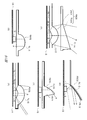
- FIG. 7 and 8 are diagrams showing the relationship between the illumination distance of the peripheral illumination light and the central illumination light and the illuminance distribution.
- FIG. 7 shows the relationship between the irradiation distance and the illuminance distribution when the outer peripheral light source 5 constitutes the peripheral illumination unit 21 and the inner peripheral light source 5 constitutes the central illumination unit 22.
- FIG. 8 shows the relationship between the irradiation distance and the illuminance distribution in the case where the inner light source 5 forms the peripheral illumination unit 21 and the outer light source 5 forms the central illumination unit 22. . That is, FIG. 8 shows the relationship between the illumination distance of the peripheral illumination light and the central illumination light and the illuminance distribution when the central illumination unit 22 is disposed outside the peripheral illumination unit 21. 7 and 8, the central illumination light distribution control unit 6b of the light distribution control unit 6 protrudes toward the emission side, and the light distribution of the central illumination light 12 is controlled by the central illumination light distribution control unit 6b. .
- FIG. 7A shows the illumination range of the peripheral illumination light 11 and the central illumination light 12 at positions separated from the light source substrate 51 in the optical axis direction of the light source 5 by distances L0 and L1 (L0 ⁇ L1).
- FIG. 7B shows the illuminance distribution of the peripheral illumination light 11 and the central illumination light 12 at positions separated from the light source substrate 51 in the optical axis direction of the light source 5 by the distances L0 and L1.
- an area illuminated by the ambient illumination light 11 at the position of the distance L0 is shown as an illumination area A1
- an area illuminated by the ambient illumination light 11 at the position of the distance L1 is shown as an illumination area A2.
- the area illuminated by the central illumination light 12 at the position of the distance L0 is indicated by the illumination area B1
- the area illuminated by the central illumination light 12 at the position of the distance L1 is indicated by the illumination area B2.
- FIG. 7A since the surrounding illumination unit 21 is arranged outside the central illumination unit 22, that is, on the opposite side of the central illumination unit 22 from the video projection unit 7, illumination areas A1 and B1 However, even if the distance L0 changes to L1, the illumination areas A2 and B2 do not intersect. In this case, as shown in FIG. 7B, an illuminance distribution shape that is not affected by the irradiation distance is obtained. In addition, the illumination intensity of each illumination light in illumination area A2, B2 is lower than the illumination intensity in illumination area A1, B1, as shown in FIG.7 (b).
- the user can arbitrarily determine the distance between the video projection illumination device 1 and the projection destination and illumination destination without being affected by the shape of the illumination distribution.
- FIG. 8A shows the illumination range of the peripheral illumination light 11 and the central illumination light 12 at positions L0 and L1 (L0 ⁇ L1) away from the light source substrate 51 in the optical axis direction of the light source 5.
- FIG. 8B shows the illuminance distribution of the ambient illumination light 11 and the central illumination light 12 at positions separated from the light source substrate 51 in the optical axis direction of the light source 5 by the distances L0 and L1.
- an area illuminated by the ambient illumination light 11 at the position of the distance L0 is shown as an illumination area B11
- an area illuminated by the ambient illumination light 11 at the position of the distance L1 is shown as an illumination area B12. .
- FIG. 8A shows the illumination range of the peripheral illumination light 11 and the central illumination light 12 at positions L0 and L1 (L0 ⁇ L1) away from the light source substrate 51 in the optical axis direction of the light source 5.
- FIG. 8B shows the illuminance distribution of the ambient illumination light 11 and the central illumination light 12 at positions separated from the light source substrate
- the area illuminated by the central illumination light 12 at the position of the distance L0 is indicated by the illumination area A11
- the area illuminated by the central illumination light 12 at the position of the distance L1 is indicated by the illumination area A12.
- the peripheral illumination light distribution control unit 6a is disposed on the inner side
- the central illumination light distribution control unit 6b is disposed on the outer side.
- the peripheral illumination unit 21 is disposed inside the central illumination unit 22, that is, between the central illumination unit 22 and the video projection unit 7, the illumination regions A11 and B11, the illumination region A12 and B12 cross each other. Moreover, in the area where the illumination light intersects, as shown in FIG. 8B, the illuminance is increased as compared with the other areas. Further, when the distance in the optical axis direction of the light source 5 from the light source substrate 51 changes from L0 to L1, the position at which the illuminance increases as compared to the illuminance distribution shape at the distance L0 changes.
- the shape of the illuminance distribution is affected by the illumination distance, so that depending on the assumed illumination distance so that the desired illuminance distribution shape can be obtained.
- the shape of the light distribution control unit 6 may be changed as appropriate.
- the shape of the central illumination light distribution controller 6b is changed so that the central illumination light 12 further illuminates the inside.
- the shape of the ambient illumination light distribution controller 6a is changed so that the ambient illumination light 11 further illuminates the outside.
- the change of the shape of the peripheral illumination light distribution control unit 6a and the change of the shape of the central illumination light distribution control unit 6b may be combined. Thereby, as shown in FIG. 8, the surrounding illumination part 21 can also be arrange
- the boundary between the light beams from each light source 5 is described in a clear manner.
- the boundary between the light beams is It may be a light distribution that attenuates from the center toward the periphery. Even in such a case, if the angle at which the light beams intersect is reduced, an illuminance distribution shape in which the influence of the illumination distance is suppressed can be obtained.
- the video projection unit 7 projects a video according to the video signal output from the control unit.
- the video projection unit 7 includes an illumination system for video projection and a projection system inside.
- the projection system projects an image by emitting image light 4 corresponding to the image signal toward the image projection area 12a.
- the illumination system emits a luminous flux of illumination correction light described later.
- an LED or a semiconductor laser is used as the light source of the illumination system of the video projection unit 7.
- DMD Digital Mirror Device
- LCD Liquid Crystal Display
- the illumination system for video projection may include, for example, a polarization conversion element, an integrator lens such as a light guide, a multi-lens, and the like.
- a video may be projected by performing laser scanning in combination with a laser light source and a two-axis MEMS (Micro Electro Mechanical Systems) mirror.
- MEMS Micro Electro Mechanical Systems
- the camera 8 shoots the object in the video projection area 12a and its surrounding area, and generates a captured image of the object. Then, the camera 8 outputs the generated captured image to the control unit 110, for example.
- the captured image generated by the camera 8 is used, for example, for acquiring luminance information such as the peripheral illumination light 11 that illuminates the video peripheral region 11a and the luminance of the video projected on the video projection region 12a.
- the captured image is used to acquire operation signals related to operations related to changes in various settings such as illumination intensity of illumination light, operations related to switching to a video playback mode and illumination mode, which will be described later, and other operations related to the video projection illumination device 1. Also used for.
- the operation signal acquisition method will be described later.
- the control part 110 acquires the operation signal regarding operation of the video projection illumination apparatus 1 based on the captured image output from the camera 8.
- the control unit 110 detects the operation of an object such as a user's hand or finger or a pointing stick from a plurality of captured images, and acquires the operation signal by analyzing the detected operation.
- the control unit 110 reads a pattern for extracting the shape of the target object stored in advance in the data storage unit 102, and extracts the shape and position of the target object by pattern matching.
- the control unit 110 detects the operation of the user's hand, finger, etc. by performing such processing on each captured image.
- the control part 110 controls each part of the video projection illumination apparatus 1 based on the acquired operation signal.
- the angle of view of the camera 8 is wider than the image projection angle of view by the image projection unit 7, and is set so that, for example, the entire image projection area 12a can be imaged. Further, it is desirable that the angle of view of the camera 8 is set so that a region further outside the video peripheral region 11a illuminated with the peripheral illumination light 11 shown in FIG.
- the camera 8 has an optical performance capable of focusing at an arbitrary position between the video projection illumination device 1 and the video projection area 12a.
- the camera 8 may have an autofocus function. According to this configuration, it is possible to acquire information such as the brightness of the projected video that is affected by, for example, illumination light, the color or material of the projection destination (video projection area 12a), etc., in the entire projectable range of the video. It becomes. Specifically, by comparing the color and brightness of the assumed video signal at a certain position with the color and brightness of the projection destination obtained from the image captured by the camera 8, the optical destination of the projection destination is compared. Feature quantities can be extracted. By analyzing and calculating this feature amount, for example, by the control unit 110 or the like, it is possible to correct the projected video so that the intended video is displayed. Thus, in the video projection illumination device 1, the projected video is automatically adjusted.
- the video projection lighting device 1 may acquire an operation signal based on the distance of the user's hand or finger measured by, for example, the TOF (Time Of Flight) method. Further, the video projection lighting device 1 may acquire an operation signal from a remote controller, a touch panel, an input button, or the like. Moreover, the video projection illumination device 1 may acquire an operation signal based on audio information input from a microphone (not shown).
- the TOF Time Of Flight
- the environment sensor 9 acquires environmental information such as the ambient environment of the video projection lighting device 1, for example, brightness and ambient color.
- the environment sensor 9 outputs the acquired environment information to, for example, the environment sensing unit 100 shown in FIG.
- the acquired environment information is used, for example, when calculating a video correction parameter for correcting the projected video.
- the video correction parameters will be described later.
- the environment sensor 9 may be connected to the control unit 110 and output the acquired environment information to the control unit 110, for example. In this case, the control unit 110 calculates the video correction parameters described above.
- the housing 10 accommodates each part shown in FIG. 1 and FIG.
- the shape of the housing 10 may be, for example, a truncated cone or cylinder in which the inside is hollow and the emission side of the peripheral illumination light 11, the central illumination light 12, and the image light 4 is opened, as shown in FIG.
- a pyramid such as a quadrangular frustum or a hexagonal frustum having an opening on the output side may be used.
- the power source 107 supplies power to each part of the video projection lighting device 1.
- the power source 107 may acquire power through an outlet, for example, or may be configured with a battery, for example.
- the environment sensing unit 100 corrects the projected image based on the environment information acquired by the environment sensor 9. For example, the environment sensing unit 100 adjusts the brightness, color, etc. of the projection video based on information such as ambient brightness and color included in the environment information so that the influence of the ambient light on the brightness and color of the projection video can be suppressed. It has a video correction function to correct. Specifically, the environment sensing unit 100 calculates a video correction parameter for correcting the video so as to obtain a desired brightness and color based on the environmental information acquired by the environmental sensor 9. Alternatively, the environment sensing unit 100 may read a predetermined video correction parameter based on the environment information from the data storage unit 102 shown in FIG. The environment sensing unit 100 outputs the calculated or read image correction parameters to the control unit 110.
- the environment sensing unit 100 may be provided in the control unit 110 described later.
- the environmental sensor 9 is connected to the control unit 110, and the acquired environmental information is output from the environmental sensor 9 to the control unit 110.
- the operation input unit 101 includes, for example, an operation signal receiving unit transmitted from a remote controller, a touch panel, an input button, and the like. For example, an operation signal from a user is directly input to a touch panel, an input button, and the like.
- the operation input unit 101 includes, for example, the camera 8 and the control unit 110.
- the camera 8 and the control unit 110 acquire an operation signal based on the motion of the object, and each unit of the video projection illumination device 1 is controlled based on the acquired operation signal.
- the data storage unit 102 is composed of, for example, a non-volatile memory, and stores various data related to the video projection illumination device 1.
- the data storage unit 102 stores, for example, a program for operating the video projection illumination device 1, various setting information, various parameters related to the ambient illumination light 11, the central illumination light 12, the image light 4, image correction parameters, and the like.
- the parameters stored in the data storage unit 102 include, for example, data indicating the relationship between the brightness and current of the ambient illumination light 11 and the ambient illumination light 11 and the central illumination light 12 that are set at the time of shipping work. Data indicating the relationship between the environmental information and the brightness of the illumination light.
- the video receiving unit 103 is connected to, for example, an external device (not shown), and receives a video signal related to a video to be projected to the video projecting unit 12a from the external device.
- the video signal here includes, for example, content linked to a smartphone, content stored in an external memory, content obtainable from the Internet, and the like.
- the video reception unit 103 may be connected to an external device by wire, or may be connected to the external device wirelessly, for example, by short-range wireless.
- the video receiving unit 103 includes a data reading unit of an external memory such as an SD card, a CD (Compact Disc), a DVD (Digital Versatile Disc), and the like, and reads the video signal stored in the external memory. Also good.
- the video receiving unit 103 outputs the received or read video signal to the control unit 110.
- the video receiving unit 103 may output the video signal to the data storage unit 102 and store the video signal in the data storage unit 102.
- the control unit 110 includes an illumination video management unit 106, an illumination control unit 104, and a video control unit 105, as shown in FIG.
- the control unit 110 controls, for example, the peripheral illumination unit 21, the central illumination unit 22, the video projection unit 7, and the like.
- the illumination video management unit 106 performs predetermined illumination control signals and video control based on various information output from the environment sensing unit 100, the operation input unit 101, the video reception unit 103, parameters read from the data storage unit 102, and the like. Generate a signal.
- the illumination video management unit 106 outputs the generated illumination control signal to the illumination control unit 104, and outputs the generated video control signal to the video control signal 105.
- the illumination control unit 104 Based on the illumination control signal output from the illumination video management unit 106, the illumination control unit 104 switches on / off the light emission of the peripheral illumination unit 21 and the central illumination unit 22, and sets the light emission intensity, the light emission color, and the like. Do.
- the video control unit 105 switches on / off of video projection by the video projection unit 7, 4 modulation or the like is performed.
- the video control unit 105 corrects the brightness, color, and the like of the projected video based on the video correction parameter output from the environment sensing unit 100.
- the video projection illumination device 1 capable of projecting a desired video even under different environmental light conditions is provided.
- control unit 110 calculates a video correction parameter based on the environment information output from the environment sensor 9.
- the illumination video management unit 106 calculates video correction parameters based on the environment information.
- the illumination video management unit 106 may read video correction parameters based on the environment information from the data storage unit 102.
- control unit 110 switches the operation mode of the video projection lighting device 1 to a menu display mode, a lighting mode, and a video playback mode, which will be described later.
- a menu display mode a lighting mode
- a video playback mode a video playback mode
- the menu display mode is a mode that accepts menu selection by the user.
- a menu video for selecting the operation mode is projected onto the video projection area 12 a, and the video peripheral area 11 a is illuminated with the peripheral illumination light 11.
- the central illumination unit 22 does not illuminate the video projection area 12a.
- the control unit 110 reads, for example, image data related to the menu video from the data storage unit 102, and generates a video control signal based on the read image data or the like.
- the control unit 110 generates an illumination control signal such that the ambient illumination light 11 is emitted from the ambient illumination unit 21 and the central illumination light 12 is not emitted from the central illumination unit 22.
- the video projection unit 7 emits video light 4 related to the menu video based on the generated video control signal.
- the ambient illumination unit 21 emits ambient illumination light 11 based on the generated illumination control signal
- the central illumination unit 22 does not emit central illumination light 12 based on the generated illumination control signal.
- the menu video may include not only a video relating to the selection of the illumination mode and the video reproduction mode, but also a video relating to various settings of the video projection lighting device 1, for example.
- the illumination mode is a mode in which emission of the ambient illumination light 11 by the ambient illumination unit 21 and emission of the central illumination light 12 by the central illumination unit 22 are simultaneously performed based on the operation signal received by the operation input unit 101.
- the video projection unit 7 does not perform video projection.
- the control unit 110 In the illumination mode, for example, the control unit 110 generates an illumination control signal that causes the ambient illumination unit 21 to emit the ambient illumination light 11 and causes the central illumination unit 22 to emit the central illumination light 12. For example, the control unit 110 generates a video control signal that prevents the video light 4 from being emitted from the video projection unit 7. Then, the ambient illumination unit 21 and the central illumination unit 22 emit the ambient illumination light 11 and the central illumination light 12 based on the generated illumination control signal. Further, the video projection unit 7 does not emit the video light 4 based on the generated video control signal. [Video playback mode]
- the video reproduction mode is a mode in which emission of the ambient illumination light 11 by the ambient illumination unit 21 and projection of an image by the video projection unit 7 are simultaneously performed based on the operation signal received by the operation input unit 101.
- the central illumination unit 22 does not emit the central illumination light 12.
- the control unit 110 In the video reproduction mode, for example, the control unit 110 generates an illumination control signal such that the ambient illumination unit 11 emits the ambient illumination light 11 and the central illumination unit 22 does not emit the central illumination light 12.
- the control unit 110 generates a video control signal for emitting the video light 4 related to a predetermined video from the video projection unit 7. Then, the ambient illumination unit 21 emits ambient illumination light 11 based on the generated illumination control signal.
- the video projection unit 7 emits video light 4 based on the generated video control signal.
- the central illumination unit 22 does not emit the central illumination light 12 based on the generated illumination control signal.
- FIG. 9 is a flowchart showing an example of a method of using the video projection lighting apparatus according to Embodiment 1 of the present invention.
- the respective processes in steps S10 to S90 are executed.
- step S10 the user operates the power supply 107 to turn on the video projection lighting apparatus 1. Then, the environmental sensor 9 acquires environmental information of the surrounding environment of the video projection lighting device 1. Then, the environmental sensor 9 outputs the acquired environmental information to the control unit 110, for example.
- step S ⁇ b> 20 the control unit 110 (for example, the illumination video management unit 106) reads out the video correction parameter based on the environmental information output from the environmental sensor 9 from the data storage unit 102.
- step S30 the illumination image management unit 106 generates an illumination control signal for emitting the ambient illumination light 11 based on the read image correction parameter. Then, the illumination video management unit 106 outputs the generated illumination control signal to the illumination control unit 104.
- the illumination control unit 104 causes the ambient illumination light 11 to be emitted from the ambient illumination unit 21 based on the output illumination control signal. Thereby, the surrounding illumination part 21 is turned ON.
- step S40 the video projection unit 7 projects a menu video onto the video projection area 12a.
- the illumination video management unit 106 reads image data related to the menu video from the data storage unit 102 and generates a video control signal based on the read image data and the like.
- the illumination video management unit 106 outputs the generated video control signal to the video control unit 105.
- the video control unit 105 causes the video projection unit 7 to emit video light 4 related to the menu video based on the output video control signal.
- the video projection illumination device 1 is set to the menu display mode.
- the control unit 110 acquires the illuminance information of the ambient illumination light 11, the brightness information of the menu video, and the like based on the captured image generated by the camera 8. Further, the environment sensor 9 may acquire new environment information even after the menu video is projected. And the illumination video management part 106 produces
- the steps S10 to S40 so far complete the standby process after the power is turned on.
- the video projection lighting device 1 enters a state of waiting for an operation signal from the user.
- the camera 8 detects an operation signal from the user, for example, by photographing an object near the video projection area 12a.
- step S50 the control unit 110 determines the detected operation signal. For example, when the control unit 110 detects an operation signal for switching to the illumination mode, the process of step S60 is performed as illustrated in FIG. On the other hand, when the control unit 110 detects an operation signal for switching to the video reproduction mode, for example, the process of step S70 is performed as shown in FIG. When the control unit 110 detects an operation signal other than these, the operation signal is detected again in step S40 as shown in FIG.
- step S60 the control unit 110 (for example, the illumination video management unit 106) generates an illumination control signal for emitting the central illumination light 12. Then, the illumination video management unit 106 outputs the generated illumination control signal to the illumination control unit 104.
- the illumination control unit 104 causes the central illumination light 12 to be emitted from the central illumination unit 22 based on the output illumination control signal. Thereby, the central illumination part 22 is turned ON. Therefore, both the surrounding illumination unit 21 and the central illumination unit 22 are turned on, and the operation mode is switched from the menu display mode to the illumination mode. Further, even after switching to the illumination mode, the control unit 110 adjusts the illuminance and the like of the ambient illumination light 11 and the central illumination light 12 based on the luminance information and new environment information. In step S60, the operation signal is continuously detected even after the operation mode is switched to the illumination mode.
- step S70 the control unit 110 (for example, the illumination video management unit 106) generates a video control signal for emitting the video light 4.
- the control unit 110 may cause the user to select content from a content selection video that selects a video to be projected, and generate a video control signal based on the selected content or the like.
- the illumination video management unit 106 outputs the generated illumination control signal to the video control unit 105.
- the video control unit 105 causes the video light 4 to be emitted from the video projection unit 7 based on the output video control signal. Thereby, an image is projected, and the operation mode is switched from the menu display mode to the image reproduction mode.
- control unit 110 adjusts the illuminance of the ambient illumination light 11, the brightness of the video light 4, and the like based on the brightness information and new environment information.
- step S70 the operation signal is continuously detected even after the operation mode is switched to the video reproduction mode.
- step S80 control unit 110 determines an operation signal detected during the illumination mode.
- the control unit 110 detects an operation signal for switching to the video reproduction mode during the illumination mode, the process of step S70 is performed as shown in FIG.
- the control unit 110 (for example, the illumination video management unit 106) stops the emission of the central illumination light 12, and then the video projection unit. 7 to project a predetermined image.
- the illumination video management unit 106 generates an illumination control signal for stopping the emission of the central illumination light 11.
- the illumination control unit 104 stops the emission of the central illumination light 12 from the central illumination unit 22 based on the generated illumination control signal. Thereby, the central illumination part 22 is turned off.
- the control part 110 implements the process etc. which radiate
- step S80 when it is determined that the operation signal for ending the illumination mode is detected, the control unit 110 performs a process of stopping the emission of the central illumination light 12. In this way, when the central portion 22 is turned off, the illumination mode ends as shown in FIG. If the control unit 110 determines that an operation signal other than these has been detected, the illumination mode is continued as shown in FIG.
- step S90 the control unit 110 determines an operation signal detected during the video playback mode.
- the control unit 110 detects an operation signal for switching to the illumination mode during the video reproduction mode, the process of step S60 is performed as shown in FIG.
- step S90 the control unit 110 (for example, the illumination video management unit 106) stops the emission of the video light 4, and then the central illumination light 12 is stopped. Is emitted.
- the illumination video management unit 106 generates a video control signal for stopping the emission of the video light 4.
- the video control unit 105 stops the emission of the video light 4 from the video projection unit 7 based on the generated video control signal. Thereby, video projection is turned off.
- the control part 110 implements the process etc. which radiate
- step S90 when it is determined that the operation signal for ending the video reproduction mode is detected, the control unit 110 performs a process of stopping the emission of the video light 4. In this way, when the video projection is turned off, the video playback mode ends as shown in FIG. If the control unit 110 determines that an operation signal other than these has been detected, the video playback mode is continued as shown in FIG.
- the control unit 110 detects a predetermined operation signal such as an object such as a user's hand or finger crossing the front of the camera 8 in the illumination mode or the video playback mode.
- the operation mode may be switched to the menu display mode.
- the menu video can be displayed at an arbitrary timing and switched to the menu display mode.
- the function of the operation input unit 101 other than the camera 8 may be used, as long as the operation input unit 101 can detect the operation of the user.
- the flowchart shown in FIG. 9 is an example of a method of using the video projection illumination device, and various modifications may be added depending on the situation. ⁇ Effects of this embodiment>
- the video projection illumination device 1 includes the video projection unit 7 that projects a video on the video projection region 12 a and the peripheral illumination unit 21 that illuminates the video peripheral region 11 a surrounding the video projection region 12. ing.
- the image projection illumination device 1 that illuminates the periphery of the projection image 14 while suppressing deterioration in image quality of the projection image 14 is provided.
- the central illumination unit 22 that illuminates the video projection region 12a is provided. According to this configuration, since the ambient illumination light 11 and the central illumination light 12 can be emitted simultaneously, the video projection illumination device 1 in which the illuminance of the illumination light is further improved is provided.
- the light distribution control unit 6 is provided in the peripheral illumination unit 21 and the central illumination unit 22. According to this configuration, since the luminous fluxes of the peripheral illumination light 11 and the central illumination light 12 are controlled to be distributed, the video projection illumination device 1 that further improves the accuracy of the emission direction of the peripheral illumination light 11 and the central illumination light 12 is provided. Provided.
- control unit 110 adjusts the illuminance of the ambient illumination light 11 based on the environmental information acquired by the environmental sensor 9. According to this configuration, the ambient illumination light 11 can be adjusted to the surrounding environment, so that the video projection illumination device 1 with improved versatility is provided.
- control unit 110 adjusts the brightness of the projected video 14 based on the environmental information acquired by the environmental sensor 9. According to this configuration, the projection video 14 can be corrected in accordance with the surrounding environment, so that the video projection illumination device 1 with improved versatility is provided.
- the light source substrate 51 is made of a material excellent in heat dissipation. Generally, when the temperature of the light source 5 rises, the light emission efficiency is lowered. However, if the light source substrate 51 having excellent heat dissipation is used, the temperature rise of the light source 5 can be suppressed. Provided. Thereby, the continuous use time can be extended, and the video projection illumination device 1 excellent in versatility is provided.
- the operation input unit 101 that receives an operation signal from the user is provided, and the video projection mode and the illumination mode are switched based on the operation signal. According to this configuration, since the projection image 14 and the central illumination light 12 are switched, the image projection illumination device 1 is provided in which the usage environment is expanded and the versatility is improved.
- the operation signal is detected based on the captured image generated by the camera 8. According to this configuration, the user can operate the video projection lighting apparatus 1 without touching the apparatus main body, so that the video projection lighting apparatus 1 excellent in handling is provided.
- FIG. 10 is a diagram showing an example of a combination of the shape of the video projection area and the shape of the video peripheral area according to Embodiment 2 of the present invention.
- the boundary between the video peripheral area 11a and the video projection area 12a is clearly shown, but the boundary is blurred as necessary, and the illuminance between the video peripheral area 11a and the video projection area 12a is increased.
- the ambient illumination light 11 may be subjected to light distribution control so as to change smoothly.
- the ambient illumination light 11 may be subjected to light distribution control so that the illuminance is smoothly attenuated toward the video projection region 12a.
- no outline or boundary may be formed outside the video peripheral area 11a.
- the light distribution control may be performed so that the ambient illumination light 11 illuminates a wide area up to a wall or a ceiling.
- the display range of the projected image 14 is indicated by a dotted rectangle.
- the projected image 14 and the image peripheral area 11a do not overlap, it is possible to provide a bright viewing environment while displaying the image with high contrast. As a result, the user can freely act even while viewing the video.
- FIG. 10A shows a combination in which the outer contour of the video peripheral region 11a is circular in plan view, and the contour of the video projection region 12a, that is, the inner contour of the video peripheral region 11a is circular in plan view.
- FIG. 10B shows a combination in which the outer contour of the video peripheral region 11a is elliptical in plan view, and the contour of the video projection region 12a, that is, the inner contour of the video peripheral region is circular in plan view.
- FIG. 10C shows a combination in which the outer contour of the video peripheral area 11a is rectangular in plan view, and the contour of the video projection area 12a, that is, the inner contour of the video peripheral area is circular in plan view.
- FIG. 10D shows a combination in which the outer contour of the video peripheral region 11a is circular in plan view, and the contour of the video projection region 12a, that is, the inner contour of the video peripheral region is elliptical in plan view.
- FIG. 10E shows a combination in which the outer contour of the video peripheral region 11a is elliptical in plan view, and the contour of the video projection region 12a, that is, the inner contour of the video peripheral region is elliptical in plan view.
- FIG. 10F shows a combination in which the outer contour of the video peripheral area 11a is rectangular in plan view, and the contour of the video projection area 12a, that is, the inner contour of the video peripheral area is elliptical in plan view. Yes.
- FIG. 10E shows a combination in which the outer contour of the video peripheral area 11a is rectangular in plan view, and the contour of the video projection area 12a, that is, the inner contour of the video peripheral area is elliptical in plan view.
- FIG. 10G shows a combination in which the outer contour of the video peripheral region 11a is circular in plan view, and the contour of the video projection region 12a, that is, the inner contour of the video peripheral region is rectangular in plan view.
- FIG. 10H shows a combination in which the outer contour of the video peripheral area 11a is elliptical in plan view, and the contour of the video projection area 12a, that is, the inner contour of the video peripheral area is rectangular in plan view.
- FIG. 10I shows a combination of the outer contour of the video peripheral area 11a being rectangular in plan view and the contour of the video projection area 12a, that is, the inner contour of the video peripheral area being rectangular in plan view.
- the outer contour of the video peripheral area 11a will be described. As shown in FIGS. 10 (a), 10 (d), and 10 (g), when the outer contour of the image peripheral area 11a is circular, the image projection illumination device 1 emits illumination light in a circular shape. It is possible to give the user the same impression as a general lighting fixture.
- FIG. 10B, FIG. 10E, and FIG. 10H when the outer contour of the video peripheral area 11a is an ellipse, the projection video 14 and the video peripheral area 11 are illustrated. Since the shape expands in the horizontal direction, the shape of the projected image and the shape of the ambient illumination light 11 can be balanced while giving the user an impression similar to that of a general lighting fixture.
- the inner contour of the image peripheral area 11a will be described. As shown in FIG. 10A, FIG. 10B, and FIG. 10C, when the inner contour of the video peripheral area 11a is circular, the contour shape of the video projection area 12a has symmetry. Regardless of the orientation of the video projection lighting device 1, it is possible to project a video without giving the user a sense of incongruity.
- FIGS. 10 (g), 10 (h) and 10 (i) when the inner contour of the video peripheral area 11a is rectangular, a rectangular projected video 14 is displayed in the video projection area 12a. In this case, the projection image 14 and the ambient illumination 11 can be balanced.
- FIG. 10 (i) when the inner contours of the projected video 14 and the video peripheral area 11a are both rectangular, the area between the projected video 14 and the video peripheral area 11a is a so-called frame. A design is provided. Further, if the projection video 14 is displayed over the entire projection video area 12a, it is possible to illuminate the periphery without any gap while a high contrast video is projected over the entire video projection area 12a.
- the brightness of the ambient illumination light 11 may be equal to the brightness of the image light 4.
- the illuminance of the peripheral illumination light 11 in the vicinity of the video peripheral region 11a is, for example, 300 lux or more.
- a design with a sense of unity may be provided by reducing the interval between the projected image 14 and the inner boundary of the image peripheral area 11a.
- a design that makes the projected video 14 stand out by increasing the interval between the projected video 14 and the inner boundary of the video peripheral area 11a may be provided.
- the width from the inner boundary to the outer boundary of the video peripheral area 11a may be wide or narrow. If the image peripheral area 11a is wide, the peripheral illumination light 11 having an impression like a general lighting fixture is provided. On the other hand, if the width of the video peripheral area 11a is narrow, the illuminance of the video peripheral area 11a can be increased even when the amount of light emitted from the light source 5 is constant as compared with the case where the width is wide. Thereby, illuminance can be improved while suppressing power consumption.
- FIG. 11 is a diagram illustrating an example of the configuration of the peripheral illumination unit and the central illumination unit according to Embodiment 2 of the present invention.
- FIG. 11A is a plan view illustrating an example of the configuration of the peripheral illumination unit 21 and the central illumination unit 22.
- FIG. 11B is a cross-sectional view illustrating an example of the configuration of the peripheral illumination unit 21 and the central illumination unit 22.
- FIG. 11C is a diagram illustrating a state of light distribution control in the peripheral illumination unit 21.
- the plurality of light sources 5 constituting the peripheral illumination unit 21 are arranged in a rectangular shape on the outer periphery in a plan view viewed from the emission side, for example, as shown in FIG.
- the ambient illumination light distribution control unit 6a that is the light distribution control unit 6 of the ambient illumination unit 21 is configured such that the curvature decreases as the distance from the video projection unit 7 increases, for example, as illustrated in FIG. . That is, the ambient illumination light distribution control unit 6 a is configured such that the lens effect is strong on the video projection unit 7 side and the lens effect is weak on the side opposite to the video projection unit 7.
- the light flux passing through the peripheral illumination light distribution control unit 6a on the video projection unit 7 side greatly affects the light distribution control as shown in FIG. 11C, for example. Because it receives, divergence is suppressed.
- the light flux passing through the peripheral illumination light distribution control unit 6a on the opposite side (outside of the image projection illumination device 1) from the image projection unit 7 side is, for example, as shown in FIG. Since the influence of the control is small, it diverges more than the light flux on the video projection unit 7 side. Therefore, the inner contour of the video peripheral area 11 a has a shape close to a rectangular shape according to the arrangement of the light sources 5.
- the outer contour of the video peripheral area 11a has a shape close to the light distribution that the light source 5 has. That is, the outer contour of the video peripheral area 11a has a shape close to a circle.
- the peripheral illumination unit 21 that can illuminate the light source 5 for one row with the inner contour shape and the outer contour shape of the image peripheral region 11a different from each other.
- the shape of the outer contour of the image peripheral area 11a it is possible to make the shape of the outer contour of the image peripheral area 11a nearly circular regardless of the arrangement shape of the light source 5.
- the lens is arranged so that the central illumination light distribution control unit 6b of the light distribution control unit 6 suppresses the divergence of the luminous flux of the light source 5 on the inner periphery. It may be configured to have an effect.
- FIG. 11 shows an example of a method for differentiating the inner contour and the outer contour of the image peripheral area 11a.
- the curvature of the peripheral illumination light distribution control unit 6a and the central illumination light distribution control unit 6b The desired illuminance distribution shape can be obtained by appropriately changing the positional relationship between the light source 5 and the ambient illumination light distribution control unit 6a and the central illumination light distribution control unit 6b.
- FIG. 12 is a diagram illustrating an example of a combination of a projected image and ambient illumination light according to Embodiment 3 of the present invention.
- the projected video 14 is projected over the video projection area 12a and the video peripheral area 11a.
- the boundary between the video peripheral area 11a and the video projection area 12a is clearly shown. However, the boundary between the video peripheral area 11a and the video projection area 12a is blurred as necessary.
- the ambient illumination light 11 may be subjected to light distribution control so as to change smoothly. For example, the light distribution control may be performed so that the ambient illumination light 11 is attenuated smoothly toward the video projection region 12a. In addition, no outline or boundary may be formed outside the video peripheral area 11a. For example, the light distribution control may be performed so that the ambient illumination light 11 illuminates a wide area up to a wall or a ceiling.
- the projected image 14 is shown as a horizontally long rectangle, but may be a circle, an ellipse, or the like.
- FIG. 12A shows a combination in which the outer contour of the video peripheral region 11a is circular in plan view, and the contour of the video projection region 12a, that is, the inner contour of the video peripheral region 11a is circular in plan view.
- FIG. 12B shows a combination in which the outer contour of the video peripheral region 11a is elliptical in plan view, and the contour of the video projection region 12a, that is, the inner contour of the video peripheral region is circular in plan view.
- FIG. 12C shows a combination in which the outer contour of the video peripheral region 11a is rectangular in plan view, and the contour of the video projection region 12a, that is, the inner contour of the video peripheral region 11a is circular in plan view. .
- FIG. 12D shows a combination in which the outer contour of the video peripheral region 11a is circular in plan view, and the contour of the video projection region 12a, that is, the inner contour of the video peripheral region is elliptical in plan view.
- FIG. 12E shows a combination in which the outer contour of the video peripheral region 11a is elliptical in plan view, and the contour of the video projection region 12a, that is, the inner contour of the video peripheral region is elliptical in plan view.
- FIG. 12F shows a combination in which the outer contour of the video peripheral region 11a is rectangular in plan view, and the contour of the video projection region 12a, that is, the inner contour of the video peripheral region is elliptical in plan view. .
- FIG. 12G shows a combination in which the outer contour of the video peripheral region 11a is circular in plan view, and the contour of the video projection region 12a, that is, the inner contour of the video peripheral region is rectangular in plan view.
- FIG. 12H shows a combination in which the outer contour of the video peripheral area 11a is elliptical in plan view, and the contour of the video projection area 12a, that is, the inner contour of the video peripheral area is rectangular in plan view.
- FIG. 12 (i) shows a combination of the outer contour of the video peripheral area 11a being rectangular in plan view and the contour of the video projection area 12a, that is, the inner contour of the video peripheral area being rectangular in plan view.
- the contrast of the projected video does not deteriorate inside the video projection area 12a, and the peripheral edge of the projected video 14 and the peripheral illumination light 11 overlap in the video peripheral area 11a.
- a video projection device 10 capable of integrating illumination and video is provided.
- the circular video projection area 12a High contrast is maintained. Therefore, in this case, for example, it is preferable to project a circular image.
- the width of the ring-shaped region where the projected image 14 and the ambient illumination light 11 overlap is substantially constant over the entire circumference, so that the balance between the high-contrast region and the low-contrast region can be made substantially constant. It becomes possible. Therefore, in an area where the projection video 14 and the ambient illumination light 11 overlap, an expression in which the ambient illumination light 11 and the projection video 14 are integrated by video control becomes possible.
- the aspect ratio of the rectangular projected video 14 and the projection It becomes possible to balance the aspect ratio of the region where the image 14 and the ambient illumination light 11 overlap.
- the aspect ratio of the projected video 14 is 16: 9
- the ratio of the horizontal direction and the vertical direction of the video projection region 12a is 16: 9
- the periphery of the projected video 14 and the boundary between the video projection region 12a and Therefore the user can have an impression that the high-contrast area and the low-contrast area are balanced.
- FIG. 13 is a diagram illustrating an example of the form of auxiliary illumination light according to the third embodiment of the present invention.
- FIG. 13A is a diagram illustrating the relationship between the ambient illumination light 11, the image light 4, and the auxiliary illumination light 15.
- FIG. 13B is a diagram illustrating the illuminance distribution of the ambient illumination light 11, the image light 4, and the auxiliary illumination light 15.
- FIG. 13C is a diagram illustrating an illuminance distribution obtained by superimposing the ambient illumination light 11, the image light 4, and the auxiliary illumination light 15.
- the image light 4 and the auxiliary illumination light 15 are indicated by broken lines, and the ambient illumination light 11 is indicated by a solid line.
- the illuminance distribution by the image light 4 and the auxiliary illumination light 15 is indicated by a broken line, the shaded portion is the illuminance distribution by the image light 4, and the other is the illuminance distribution by the auxiliary illumination light 15.
- the illuminance distribution of the ambient illumination light 11 is indicated by a solid line.
- the shape of the illuminance distribution may be read as the shape of the luminance distribution.
- the auxiliary illumination light 15 adjusts the luminance of the video projected on the video projection area 12a and the illuminance of the video peripheral area 11a.
- the video projection unit 7 emits a light beam that is a combination of arbitrary video light 4 and illumination correction light 15.
- the video projection unit 7 illuminates correction light that cancels the attenuation of the area illumination light 11 with respect to a region where the illuminance attenuates inward (projected video 14 side). 15 is emitted together with the image light 4.
- FIG. 13C a substantially uniform illuminance distribution is obtained from the image light 4 toward the ambient illumination light 11.
- the ambient illumination light 11 and the projection image 14 are integrated, and an image is projected into the ambient illumination light 11. It is possible to express the image as if it were.
- FIG. 14 is a diagram showing other examples relating to video control using auxiliary illumination light according to Embodiment 3 of the present invention.
- FIG. 14A shows the respective illuminance distributions when the ambient illumination light 11 and the image light 4 are separated from each other and the auxiliary illumination light 15 is smoothly attenuated from the ambient illumination light 11 toward the image light 4.
- FIG. 14B shows an illuminance distribution in which the peripheral illumination light 11, the image light 4, and the auxiliary illumination light 15 in FIG.
- the illuminance distribution when the ambient illumination light 11 and the illumination correction light 15 are superimposed is attenuated substantially exponentially toward the center. ing.
- the illuminance decreases smoothly. felt. Therefore, it is possible to project the peripheral illumination light 11 having an illuminance distribution that naturally decreases smoothly and an arbitrary image with high contrast.
- FIG. 14C the ambient illumination light 11 and the image light 4 are separated from each other, the image light 4 is smoothly attenuated toward the periphery (toward the ambient illumination light 11), and the auxiliary illumination light 15 is ambient illumination.
- FIG. 14D shows an illuminance distribution obtained by superimposing the peripheral illumination light 11, the image light 4, and the auxiliary illumination light 15 in FIG.
- an image is provided in which the ambient illumination light 11 is once darkened toward the center, and the image fades in from the darkened area toward the center.
- FIG. 14E the ambient illumination light 11 and the image light 4 overlap at the peripheral edge of the projection image 14, the image light 4 is smoothly attenuated toward the ambient illumination light 4, and the auxiliary illumination light 15 is the image light 4.
- FIG. 14F shows an illuminance distribution obtained by superimposing the peripheral illumination light 11, the image light 4, and the auxiliary illumination light 15 in FIG.
- the image is faded in toward the center from the area where the image is dark so that the image is melted into the ambient illumination light 11 while the ambient illumination light 11 is smoothly darkened toward the center.
- a video like this will be provided.
- FIG. 14G shows the respective illuminance distributions when the ambient illumination light 11 and the image light 4 overlap at the peripheral edge of the projection image 14 and the image light 4 is strong in the overlapping region. Yes.
- the auxiliary illumination light 15 is not emitted.
- FIG. 14H shows an illuminance distribution obtained by superimposing the ambient illumination light 11 and the image light 4 in FIG.
- an image in a region overlapping with the ambient illumination light 11 is emphasized, so that a decrease in contrast and a color shift due to the ambient illumination light 11 can be suppressed.
- FIG. 15 is a diagram illustrating an example of a video projection illumination device according to Embodiment 4 of the present invention.
- FIG. 15A is a perspective view of the video projection illumination device
- FIG. 15B is a cross-sectional view of the video projection illumination device.
- FIG. 15B a cross-sectional shape in the vicinity of the light source 405 is shown, and the positional relationship between the light source 405 and the video projection unit 7 is shown.
- the center illumination part 6 shown in FIG.1 (b) is abbreviate
- the video projection lighting device 401 includes a housing 410.
- the housing 410 is configured in a truncated pyramid shape such as a hexagonal truncated cone as shown in FIG.
- casing 410 may be comprised by the cylinder and the truncated cone shape, for example.
- a light source 405 is provided on the side wall 451 of the housing 410. Specifically, the light source 405 is disposed on the outer surface of the housing 410 as shown in FIGS. 15A and 15B, for example. Therefore, the light beam of the light source 405 is emitted toward the outside of the housing 410.
- the side wall 451 of the housing 410 may be made of the same material as the light source substrate 51 shown in FIG.
- the side wall 451 also functions as a light source substrate for the light source 405.
- the light source 405 is not provided with a light distribution control unit, and a plurality of light sources 405 constitute the ambient illumination unit 421.
- the light source 405 is configured by, for example, an LED that emits Lambertian light, as in the light source 5 shown in FIG.
- a light source that emits Lambert light has the property of emitting the strongest light in the normal direction of the emission surface and emitting the weakest light in the direction parallel to the light emission surface.
- the ambient illumination light 11 By utilizing this property, it is possible to prevent the ambient illumination light 11 from being emitted to the video projection region 12a by adjusting the angle of the light emitting surface of the light source 5. For example, as shown in FIG. 15B, if the angle of the light emitting surface of the light source 405 is adjusted to be parallel to the irradiation angle of the video light 4 by the video projection unit 7, the video light 4 and the ambient illumination light A light distribution that does not overlap with 411 is realized.
- the peripheral illumination unit 421 can illuminate not only the periphery of the projected image but also the wall and ceiling around the image projection illumination device 401 over a wide range.
- FIG. 16 is sectional drawing which shows the modification of the light distribution control part which concerns on Embodiment 5 of this invention.
- FIG. 16A shows an ambient illumination light distribution control unit in which a concave portion is provided on the incident surface.
- the peripheral illumination light distribution control unit 506a is provided with a recess 516a on the incident surface 6c.
- the concave portion 516a is provided so as to be within the range of the convex portion 517a of the ambient illumination light distribution control unit 506a in plan view.
- the recess 516a is configured to surround the emission surface of the light source 5.
- the ambient illumination light distribution control unit 506a is provided such that the emission surface of the light source 5 is disposed inside the recess 516a.
- the concave portion 516a is provided, for example, such that the central axis thereof coincides with the optical axis of the light source 5.
- the concave portion 516a is provided so that its central axis is on the inner side of the central axis of the convex portion 517a, that is, on the video projection unit 7 side.
- the outgoing light beam incident on the peripheral illumination light distribution control unit 506a is refracted toward the convex portion 517a in the concave portion 516a. Therefore, the peripheral illumination light distribution control unit 506a includes the case where the concave portion 516a is not provided. In comparison, more light flux is collected, and highly efficient light distribution control becomes possible.
- the light exit surface of the light source 5 is provided in the recess 516a, the light beam emitted in the surface direction of the light exit surface is subjected to light distribution control, thereby enabling highly efficient light distribution control.
- the concave portion 516a is configured such that a light beam in the surface direction of the emission surface of the light source 5 is incident on the convex portion 517a. According to this configuration, since the luminous flux in the surface direction is also subjected to light distribution control and used as ambient illumination light, more efficient light distribution control can be performed.
- the ambient illumination light distribution control unit 506a may be provided with a diffusion surface or a light shielding surface for preventing stray light in a region other than the concave portion 516a on the incident side or a region other than the convex portion 517a on the emission side. Thereby, generation
- FIG. 16B shows an ambient illumination light distribution control unit using multiple reflections.
- the ambient illumination light distribution control unit 506b in FIG. 16B is configured to have a larger curvature than the ambient illumination light distribution control unit 6a illustrated in FIG. For this reason, a part of the light beam emitted from the light source 5 causes total reflection twice on the wall surface in the convex portion 517 b and is emitted in the direction opposite to the emission direction of the light source 5. For example, a light beam emitted in a direction perpendicular to the emission surface of the light source 5 is emitted in a direction opposite to the emission direction of the light source 5 due to total reflection in the convex portion 517b.
- the light flux from the light source 5 is emitted toward the rear of the light source 5 by total reflection, so that the ceiling, the wall, or the interior of the appliance in a direction different from the image projection direction is illuminated. .
- the light beam is emitted in the direction in which it is desired to emit light strongly without changing the arrangement of the light sources 5. This also reduces the number of parts for changing the direction of the light beam.
- this configuration since there are a light beam emitted in the gazette by total reflection and a light beam transmitted and refracted by the convex portion 517b and emitted to the image projection side, various light distributions are realized. .
- FIG. 16C shows an ambient illumination light distribution control unit using total reflection.
- the ambient illumination light distribution control unit 506c in FIG. 16C is made of, for example, a transparent material.
- a part of the light beam emitted from the light source 5 is totally reflected by the wall surface 517c and emitted from the wall surface 518c to the outside.
- the light beam emitted in the direction perpendicular to the emission surface of the light source 5 is reflected by the wall surface 517c and emitted from the wall surface 518c to the outside.
- the emission direction can be greatly changed as compared with the method using refraction, the ambient illumination light 11 is emitted in a wider range. Further, since the light beam emitted from the light source 5 is totally reflected by the wall surface 517c, light distribution control is performed with higher efficiency than using a reflection film that generally absorbs a part of light.
- FIG. 16 (d) shows another example of the ambient illumination light distribution control unit using reflection.
- the ambient illumination light distribution control unit 506d is composed of a structure having a reflective surface.
- the ambient illumination light distribution control unit 506d is made of, for example, an opaque and highly rigid metal or resin.
- the ambient illumination light distribution control unit 506d may be configured with a reflector 518d and a support 517d that supports the reflector 518d, for example, as illustrated in FIG.
- the reflector 518d may be made of, for example, a metal that performs specular reflection such as a mirror, a dielectric multilayer film, or the like.
- the reflector 518d may be formed on the support 517d by metal vapor deposition, for example, or may be formed by attaching a reflective film to the support 517d.
- the reflector 518d may have a rough surface having diffusibility or a reflective surface for scattering and reflecting as required. The angle at which the emission direction of the light beam is bent can be changed more greatly in reflection than in refraction. When the emission direction of the light beam from the light source 5 is greatly changed, it is effective to use reflection in the light distribution control unit 6 as shown in FIGS. 16C and 16D, for example.
- the ambient illumination light distribution control unit 506d may be configured in combination with a transmissive resin. According to this configuration, since the light distribution emitted from the light source 5 is controlled even in the portion made of the transmissive resin, various light distributions are realized.
- the ambient illumination light distribution control unit 506d may be formed by integrally forming a portion having the reflector 518d and a transparent portion. According to this configuration, the assemblability of the ambient illumination light distribution control unit 506d is improved.
- FIG. 16D shows an example in which the cross-sectional shape is a paraboloid, the central axis thereof passes through the center of the light emitting surface of the light source 5, and the light source 5 is located near the focal point of the paraboloid. Yes.
- the design of the emission direction is facilitated.
- the divergence angle of the emitted light beam increases as the light emitting surface of the light source 5 becomes larger. Further, the divergence angle of the emitted light beam increases as the focal length of the paraboloid becomes shorter. When the light source 5 is shifted from the focal position, a light distribution with a spread at the bottom of the light distribution that is smoothly attenuated toward a wide angle is realized.
- FIG. 16 (e) shows an ambient illumination light distribution control unit using a prism.
- the ambient illumination light distribution control unit 506e includes a first ambient illumination light distribution control unit 506f and a second ambient illumination light distribution control unit 506g.
- the first ambient illumination light distribution control unit 506f includes a concave portion 516f on the incident side and a convex portion 517f on the outgoing side.
- the first ambient illumination light distribution control unit 506f converges the divergence of the light beam emitted from the light source 5.
- the concave portion 516f and the convex portion 517f are provided such that their central axes substantially coincide with the optical axis of the light source 5. Therefore, the light beam is emitted from the convex portion 517f almost symmetrically with respect to the central axis.
- the second ambient illumination light distribution control unit 506g includes a prism 517g and the like. As shown in FIG. 16E, the prism 517g is provided to face the convex portion 517f of the first ambient illumination light distribution control unit 506f. For example, as shown in FIG. 16 (e), the prism 517g has a short length in the central axis direction of the light source 5 or the like on the inner side (video projection unit 7 side) and on the outer side (opposite side of the video projection unit 7). It is configured to be long.
- the prism 517g changes the emission direction by refracting the light beam emitted from the convex portion 517f. For example, as shown in FIG.
- the outer prism 517g changes the emission direction of the light beam more outward than the inner prism 517g. It is desirable that the prism 517g be disposed so as to cover the existing range of the light beam emitted from the convex portion 517g.
- the ambient illumination light distribution control unit 506e may arbitrarily change the emission direction of the light flux after transmission, or may not change the emission direction while maintaining the optical axis direction.
- the central axis of the convex portion 517f provided in the vicinity of the light source 5 may be shifted outward.
- the convex portion 517f only needs to have symmetry.
- the prism 517g can be configured without any problem. According to this configuration, the function can be divided so as to suppress the divergence of the light beam by the lens and change the emission direction in the prism 517g, so that the degree of freedom in design regarding light distribution control is improved.
- the order of the first ambient illumination light distribution control unit 506f and the second ambient illumination light distribution control unit 506g may be switched.
- the prism 517g may be provided not on the emission side but on the light source 5 side. If the prism 517g is provided on the light source side, the emission direction of the light beam becomes larger.
- the second ambient illumination light distribution control unit 506g may be configured by a lens instead of the prism 517g.
- the divergence angle of the light beam can be freely adjusted after passing through the first ambient illumination light distribution control unit 506f, so that the light distribution can be broadened or the divergence can be suppressed. It becomes.
- the first ambient illumination light distribution control unit 506f and the second ambient illumination light distribution control unit 506g may be configured to be connected to each other by, for example, a movable casing component, and the relative arrangement thereof may be adjusted. Good. By adjusting these relative arrangements, the light distribution is freely changed, and the user can change the divergence angle of the emitted light beam.
- FIG. 17 is a cross-sectional view showing an example of light distribution control using the diffusion cover according to Embodiment 6 of the present invention.
- the left side of the video projection illumination device 601 is shown enlarged.
- FIG. 17 illustrates the case where the ambient illumination light distribution control unit 506d illustrated in FIG. 16D is used as the ambient illumination unit.
- the ambient illumination light distribution control unit is, for example, illustrated in FIG. (C), FIG. 16 (e) and the like may be provided.
- the diffusion cover 650 is provided on the emission side of the ambient illumination unit 621 as shown in FIG. Specifically, the diffusion cover is provided so as to cover the peripheral illumination unit 621 and the central illumination unit 622 from the emission side of the peripheral illumination unit 621 and the side surface side of the video projection illumination device 601.
- the diffusion cover 650 may be provided so as to fit into the housing 10 shown in FIG.
- the diffusion cover 650 diffuses the ambient illumination light 611 and the central illumination light 612.
- the diffusion cover 650 may be made of a material having fine particles, or may be made of a transparent material provided with a rough surface. Further, the diffusion cover 650 may have transparency.
- the diffusion cover 650 performs light distribution control for diffusing the emitted light beam in all directions using fine particles, a rough surface, or the like. Further, when the diffusion cover 650 is transmissive, the light beam incident on the diffusion cover 650 is hardly emitted to the light source 5 side.
- the luminous flux from the light source 5 arranged on the outer periphery is reflected by the peripheral illumination light distribution control unit 506d, and illuminates the diffusion cover 650 on the side surface side.
- the illuminated diffusion cover 650 on the side surface emits light as a secondary light source by diffusing and transmitting the incident light beam. If the diffusion of the light beam is strong, the diffusion cover 650 emits light with a light distribution according to the cos rule and emits ambient illumination light 611. That is, in this case, the transmitted light from the diffusion cover 650 exhibits optical characteristics close to a surface light source that emits Lambert light.
- the light flux from the light source 5 arranged on the inner periphery illuminates the diffusion cover 650 located on the video projection side of the video projection illumination device 601.
- the image projection side diffusion cover 650 emits light as a secondary light source and emits central illumination light 612 toward the image projection region 12a.
- the ambient illumination light 611 that illuminates the periphery is provided without the ambient illumination light 611 being emitted toward the center of the video projection device 601.
- the video projection illumination device 601 is provided in which a wide area such as a wall or a ceiling is illuminated without the video projection region 12a being illuminated by the ambient illumination light 611.
- the angle of the side surface of the diffusion cover 650 is adjusted so that the tangent plane extending from the side diffusion cover 650 does not intersect the projection image 14. It only has to be done.
- FIG. 18 is a diagram illustrating an example of orientation control using a diffusion cover having different diffusion performances on the side surface side and the video projection side in the sixth embodiment of the present invention.
- the peripheral illumination light distribution control unit 606 a and the central illumination light distribution control unit 606 b of the light distribution control unit 6 protrude toward the emission side.
- the light beams emitted from the peripheral illumination light distribution control unit 606a and the central illumination light distribution control unit 606b both illuminate the diffusion cover 650 on the image projection side and do not illuminate the diffusion cover 650 on the side surface. It is configured.
- the diffusion cover 650 is configured such that, for example, the side surface side of the video projection illumination device 601 has higher diffusion performance than the video projection side. That is, the diffusion cover 650 on the side surface side is mixed with more fine particles than the image projection side or has a rougher surface that is stronger.
- the diffusion performance of the diffusion cover 650 increases, the light distribution of the light beam emitted from the diffusion cover becomes close to Lambert light emission, so that substantial light distribution control cannot be performed in the diffusion cover 650.
- the light distribution control unit 6 is configured so that the light fluxes emitted from the light sources 5 on the outer periphery and the inner periphery are emitted to the diffusion cover 650 on the image projection side, the diffusion performance is improved. Since it is low, diffusion of the light beam is suppressed, and the emitted light beam can be used for ambient illumination light and central illumination light.
- the diffusion cover 650 may have a configuration in which the video projection side is removed instead of lowering the diffusion performance on the video projection side.
- the diffusion performance is made different between the side surface side and the video projection side has been described, but the diffusion performance of the diffusion cover 650 may be different for each region so as to obtain a desired light distribution.
- the diffusion cover 650 may be configured to be transparent in a predetermined region according to the diffusion performance, or may be configured to be removed.
- the diffusion cover 650 on the side surface has high diffusion performance, a design that does not show the internal structure of the video projection illumination device 601 is provided.
- FIG. 19 is a cross-sectional view showing an example of a modification of the light source according to Embodiment 7 of the present invention.
- a light guide 752 is disposed between the light source 5 and the light distribution control unit 6. The light guide 752 guides the light beam emitted from the light source 5 to the light distribution control unit 6.
- the light guide 752 is disposed, for example, between the outer peripheral light source 5 and the peripheral illumination light distribution control unit 6a, and guides the light beam emitted from the outer peripheral light source 5 to the peripheral illumination light distribution control unit 6a.
- the light guide 752 may be disposed, for example, between the inner peripheral light source 5 and the central illumination light distribution controller 6b.
- the light guide 752 is configured in a columnar shape such as a cylindrical shape, a quadrangular column, a polygonal column, or a column, for example.
- the highly efficient peripheral illumination light 11 or Central illumination light 12 is provided.
- the shape of the entrance surface 752a and the shape of the exit surface 752b may be different.
- the shape of the incident surface 752 is substantially the same as the shape of the light emitting surface of the light source 5, and the shape of the exit surface 752 b is a predetermined shape that matches the shape of the light distribution control unit 6.
- the light distribution control unit 6 has an imaging system structure such as a lens, the light distribution shape of the light beam emitted from the light source 5 disposed at the focal length of the lens is distributed after the light distribution control is performed. It becomes the same as the shape of the light distribution.
- the light guide 752 is configured in this way, light distribution control by the light exit surface 752b of the light guide 752 becomes possible. Further, if the area of the exit surface 752b of the light guide 752 is larger than the area of the entrance surface 752a, the luminous flux is efficiently guided to the light distribution control unit 6 using total reflection, and highly efficient illumination light is emitted. Provided. In addition, if the area of the exit surface 752b of the light guide 752 is smaller than the area of the entrance surface 752a, the divergence of the light beam can be suppressed every time the reflection is repeated on the side surface, so that a light beam close to parallel light is emitted.
- the light guide 752 may be made of, for example, a transparent material, or may have a side surface having a reflective surface.
- a transparent material for example, fine particles for adjusting the diffusion performance may be mixed in the light guide 752, and a rough surface is provided on the exit surface facing the light distribution control unit 6. May be.
- the light beam emitted from the light source 5 is scattered while being repeatedly reflected inside the light guide 752, so that the light beam is mixed inside the light guide 752.
- unevenness in the illuminance distribution of the light flux generated on the light emitting surface of the light source 5 is eliminated.
- the illuminance of the light beam emitted from the emission surface 752b of the light guide 752 is made uniform, and high-quality peripheral illumination light 11 and central illumination light 12 are provided.
- FIG. 20 is a diagram showing another modification of the light source according to Embodiment 7 of the present invention.
- a light source 805 illustrated in FIG. 20 includes, for example, a semiconductor laser 853 and a phosphor 854.
- the light source 805 emits a light beam when the phosphor 854 is excited by the semiconductor laser emitted from the semiconductor laser 853.
- the semiconductor laser 853 is used, the light emitting region of the laser is narrowed down, and the phosphor 854 can be configured to be small.
- a small region of the phosphor 854 can emit light to create a minute light emission point. If the light emission point is small, light distribution control by the light distribution control unit 6 is facilitated, so that the optical system constituting the light distribution control unit 6 can be downsized and more effective light distribution control can be performed.
- FIG. 21 is a diagram showing another modification of the light source according to Embodiment 7 of the present invention. It is a figure which shows the other modification of a light source.
- FIG. 21A is a cross-sectional view showing the positional relationship between the light source 905 and the light distribution control unit 6.
- FIG. 21B is a diagram illustrating an example of the two-dimensional modulation light emitting surface 955 of the light source 905.
- a light source 905 illustrated in FIG. 21A is configured by, for example, an OLED (Organic Light Emitting Diode). On the emission side of the light source 905, for example, as shown in FIGS.
- OLED Organic Light Emitting Diode
- a two-dimensional modulation unit 955 that two-dimensionally controls the shape, light emission intensity, color, and the like of the light beam emitted from the light source 905.
- the two-dimensional modulation unit 955 controls the shape, light emission intensity, color, and the like of the light beam emitted from the light source 905.
- FIG. 21B shows the case where the two-dimensional modulation unit 955 is configured so that the light beam is emitted in an arrow shape, but the shape of the light beam can be arbitrarily adjusted by changing the configuration. Is possible.
- a light source 905 and a liquid crystal display element may be combined in the light source portion.
- the light distribution control unit 6 since the light emission intensity, color, and the like of the light source 905 are also controlled, the light distribution after being emitted from the light distribution control unit 6 is dynamically controlled. Thereby, the light distribution of illumination light can be controlled in detail.
- FIG. 22 is a diagram showing another modification of the light source according to Embodiment 7 of the present invention.
- FIG. 22A is a cross-sectional view showing the positional relationship between the light source 1005 and the light distribution control unit 6.
- FIG. 22B shows the light source part and the light distribution control unit 6 separately.
- a light source 1005 shown in FIG. 22 is configured in an annular shape.
- the light source 1005 is comprised by OLED, for example.
- the light source 1005 is arranged separately on the outer periphery and the inner periphery.
- the outer peripheral light source 1005 constitutes, for example, the peripheral illumination unit 11
- the inner peripheral light source 1005 constitutes, for example, the central illumination unit 12.
- These light sources 1005 emit light in an annular shape.
- the ambient illumination light distribution control unit 6a and the central illumination light distribution control unit 6b of the light distribution control unit 6 are configured in an annular shape according to the shape of the light source 1005, for example, as shown in FIG.
- FIG. 22B illustrates the case where the light source 1005 for the outer periphery and the inner periphery is provided, but the light source 1005 is provided only for one turn, which is the minimum configuration, for example. Alternatively, three or more turns may be provided to enable finer light distribution control.
- the light source 1005 for example, a light source unit in which a diffusion surface and a large number of minute light sources are combined may be used.
- the circumferential light distribution is a continuous shape, the peripheral illumination light 11 and the central illumination light 12 having a smooth and high-quality light distribution are provided.
- the direction of the user's finger as viewed from the pupil position of the camera lens is only specified, and arbitraryness remains in specifying the position of the object in the three-dimensional space. Therefore, in the present embodiment, a method for acquiring three-dimensional position information will be described.
- FIG. 23 is a diagram showing an example of a method for acquiring three-dimensional position information according to Embodiment 8 of the present invention.
- illumination control is performed such that a plurality of light sources 5 such as the light sources 5A and 5B (partial light sources) are sequentially emitted.
- the camera 8 photographs the object and the shadow of the object.
- the camera 8 generates a plurality of captured images corresponding to the plurality of light sources 5. From each captured image, the shadow of the object is extracted after the direction of the object viewed from the camera 8 is specified, because the extracted shadow is generated by the illumination light from the lit light source 5.
- the camera 8 may generate a captured image corresponding to each light source 5. Therefore, since the direction of the target object seen from the radiation
- the target object for acquiring the position information is not limited to these, and may be, for example, a rod-like object.
- the light source 5 is switched at high speed so as not to cause flickering in human eyes, for example. For example, if the light source 5 is switched at a frequency of 180 Hz or higher, it is difficult for the human eye to see. Therefore, it is desirable to switch the light source 5 at a frequency higher than that.
- a light source that emits invisible light having a wavelength band of an invisible region such as infrared light may be separately provided for detecting the position of the object. Even if the invisible light is emitted so as to overlap the projected image 14, the contrast of the projected image 14 is not lowered. According to this configuration, it is possible to sequentially turn on the invisible light source without causing flickering in human eyes regardless of the lighting cycle.
- the light source 5 that emits the illumination light and the light source that emits the invisible light source are used at the same time, the three-dimensional position information of the object is acquired without affecting the illumination light.
- the invisible light source may be configured to illuminate a wider area. Thereby, the acquisition range of three-dimensional position information is expanded.
- a light distribution control unit corresponding to the invisible light source may be separately provided.
- the divergence of invisible light is suppressed, the irradiation energy density is increased, and the shadow can be emphasized, and the detection accuracy of the three-dimensional position information is improved.
- FIG. 24 is a diagram illustrating an example of the configuration of the light distribution control unit according to the ninth embodiment of the present invention.
- FIG. 24A is a plan view of the light distribution control unit viewed from the emission side.
- FIG. 24A is a plan view of the light distribution control unit viewed from the emission side.
- FIG. 24B is a diagram illustrating an example of the configuration of the light distribution control unit.
- the left side in the drawing is an enlarged plan view
- the right side in the drawing is an enlarged sectional view
- FIG. 24C is a diagram illustrating an example of another configuration of the light distribution control unit, in which the left side in the drawing is an enlarged plan view and the right side in the drawing is an enlarged sectional view.
- each orientation control unit 1106 is configured in a substantially rectangular shape in plan view.
- the light distribution control unit 1106 can control the divergence of the light beam emitted from the light source 5 in a rectangular shape. Thereby, the light distribution control unit 1106 is provided with the image projection illumination device 1101 that can control the light beam emitted from the light source 5 in the circumferential direction of the ring.
- the light distribution control unit 1106 may be constituted by, for example, an aspheric lens and may have an optical function in which spherical aberration is suppressed. Further, the light distribution control unit 1106 may be configured by a free-form surface lens, and may be configured to adjust not only spherical aberration but also the light distribution of the light beam in the circumferential direction and the radial direction.
- the light source 5 of the video projection illumination device 1101 may be configured to be individually switched on / off.
- the control unit 110 individually controls ON / OFF of the light source 5.
- a light beam adjusting member 1156 that adjusts the shape of the light beam emitted from the light source 5 may be provided between the light source 5 and the light distribution control unit 1106.
- the light flux adjusting member 1156 is made of a light-shielding or reflective material.
- the light beam adjusting member 1156 has an opening 1156a in a region facing the light source 5, and the shape of the light beam from the light source 5 is adjusted by the opening 1156a. The light is emitted to the light distribution control unit 1106.
- the shape of the light beam emitted from the light source 5 is adjusted by the light beam adjusting member 1156, a desired light distribution can be obtained regardless of the shape of the light emitting surface of the light source 5. Further, the light distribution control in the light distribution control unit 1106 is performed with high accuracy.
- a protective plate 1157 may be provided between the light source 5 and the light flux adjusting member 1156.
- the protective plate 1157 can prevent the light flux adjusting member 1156 from being damaged.
- the protective plate 1157 may be made of, for example, an insulating material. Thereby, electric shock from the light source 5 and the light flux adjusting member 1156 can be prevented. Note that the order of the light flux adjusting member 1156 and the protective plate 1157 may be interchanged.
- the light flux adjusting member 1156 and the protective plate 1157 may be integrally formed. Thereby, the manufacturing cost of the light beam adjusting member 1156 and the protective plate 1157 is reduced.
- the light flux adjusting member 1156 may be formed on the protective plate 1157 by printing, for example. As a result, the light flux adjusting member 1156 is formed with higher accuracy than in general machining, so that precise light distribution control is possible.
- FIG. 24A shows an example in which the light sources 5 are arranged in two rows. However, only one row may be arranged as the minimum necessary configuration, for example, three or more rows are provided. It may be. Further, the arrangement of the light sources 5 is not limited to a concentric circle (annular) in plan view, and may be, for example, a rectangle or other shapes.
- FIG. 25 is a diagram showing an example of the illuminance distribution when a plurality of video projection illumination devices according to Embodiment 9 of the present invention are used side by side.
- a plurality of video projection devices 1101 in FIG. 24A are arranged side by side, a plurality of video light 4A and video light 4B are connected to provide one large video.
- the ambient illumination light of one image display illumination device 1101 that emits the image light 4A is 1111A.
- the ambient illumination light 1111A does not overlap the image light 4A, but overlaps the image light 4B emitted from the other image projection illumination device 1101.
- one video display illumination device 1101 that emits the video light 4A includes, for example, the light source 5 that illuminates the peripheral illumination light 1111A in a region overlapping the video peripheral region 11B and the video projection region 12B of the other video projection illumination device 1101. It is turned off so that the ambient illumination light 1111A does not overlap the image light 4B and the ambient illumination light 1111B.
- the other video display illumination device 1101 that emits the video light 4B illuminates the peripheral illumination light 1111B in a region overlapping the video peripheral region 11A and the video projection region 12A of the one video projection illumination device 1101, for example.
- the light source 5 is turned off so that the ambient illumination light 1111B does not overlap the image light 4A and the ambient illumination light 1111A.
- the control unit 110 performs such ON / OFF switching of the light source 5.
- peripheral illumination lights 1111A and 1111B are divided and controlled in the circumferential direction, a plurality of image lights 4A and 4B emitted from the plurality of image projection illumination devices 1101 are combined to produce one larger projected image. Is provided. Moreover, according to this structure, one larger surrounding illumination light surrounding one large projection image is provided by the surrounding illumination lights 1111A and 1111B of the plurality of image projection illumination devices 1101. Also, a larger projected image with higher contrast and a wider range of ambient illumination light are provided simultaneously.
- Video projection illumination apparatus 4 ... Video light, 5 ... Light source, 6 ... Light distribution control part, 6a ... Peripheral illumination light distribution control part, 6b ... Central illumination light distribution control part, 7 ... Video projection part, 8 ... Camera (Imaging part), 9 ... environmental sensor, 11 ... ambient illumination light, 11a ... ambient illumination area (second area), 12 ... central illumination light, 12a ... video projection area (first area), 14 ... projected video 15 ... Auxiliary illumination light, 21 ... Ambient illumination unit, 22 ... Central illumination unit, 101 ... Operation input unit, 110 ... Control unit, 650 ... Diffusion cover, 752 ... Light guide, 853 ... Semiconductor laser, 854 ... Phosphor , 955 ... Two-dimensional modulation unit
Abstract
The present invention is provided with: a video projection unit that projects video onto a first region; and a peripheral lighting unit that emits a luminous flux of peripheral light that illuminates a second region surrounding the first region.
Description
本発明は、映像投射照明装置に関するものである。
The present invention relates to a video projection illumination device.
周辺の照明により、視野範囲の視認性を向上させたり、表示された画像の臨場感を向上させた各種装置が提供されている。
Various devices have been provided that improve the visibility of the visual field range and improve the realistic sensation of the displayed image by surrounding illumination.
例えば、特許文献1には、レンズを透過する照明光が、中央が暗く、周辺がリング状に明るくなるよう配光されるよう構成された内視鏡が開示されている。この内視鏡では、光学素子から出射された照明光が、視野範囲の周辺をリング状に照明することにより、使用時における管内壁面などの視野範囲が効率よく重点的に照明される。
For example, Patent Document 1 discloses an endoscope configured such that illumination light transmitted through a lens is distributed so that the center is dark and the periphery is brightened in a ring shape. In this endoscope, the illumination light emitted from the optical element illuminates the periphery of the visual field range in a ring shape, so that the visual field range such as the inner wall surface of the tube at the time of use is efficiently and preferentially illuminated.
また、特許文献2には、画像表示装置の画面に写し出された画像に連動して鑑賞空間の照明を制御することにより、画像表示装置の画面に映し出された画像の臨場感を高めることができる照明方法及び照明装置が開示されている。画像の臨場感を高めるために、照明装置は、例えば、鑑賞空間の照明のレベル、光色、配光、及び方向のうち少なくとも一つのパラメータを、画像表示装置に映しだされる画像から仮想される仮想画像空間における対応するパラメータにほぼ一致させるように、鑑賞空間に設けられている一つ以上の光源を制御する。
Japanese Patent Application Laid-Open No. 2004-228561 can enhance the sense of realism of an image displayed on the screen of the image display device by controlling the illumination of the viewing space in conjunction with the image displayed on the screen of the image display device. An illumination method and an illumination device are disclosed. In order to enhance the realistic sensation of an image, for example, the lighting device is virtualized from an image displayed on the image display device with at least one of the illumination level, light color, light distribution, and direction of the viewing space. One or more light sources provided in the viewing space are controlled so as to substantially match the corresponding parameters in the virtual image space.
特許文献1で開示された内視鏡では、光学素子は、ライトガイドから受け入れた照明光を出射端から出射するが、領域毎に照明光の明るさを制御することができない。また、出射される照射光は、一般照明用としての明るさが十分ではない。
In the endoscope disclosed in Patent Document 1, the optical element emits the illumination light received from the light guide from the emission end, but the brightness of the illumination light cannot be controlled for each region. Moreover, the emitted illumination light is not bright enough for general illumination.
また、特許文献2では、画像表示装置と照明装置とが別体で構成されている。このため、利用者は、画像表示装置と、その鑑賞空間に合わせた照明装置を別途用意した上で、画像の臨場感が向上するよう、画像と照明光とを調整する必要がある。しかし、これらを一体化しただけでは、画像と照明光とが重なる等、画像と照明光との調整が十分になされないことにより、画質が劣化する場合があった。
Further, in Patent Document 2, the image display device and the illumination device are configured separately. For this reason, the user needs to separately prepare an image display device and an illumination device suitable for the viewing space, and then adjust the image and the illumination light so that the sense of reality of the image is improved. However, the image quality may deteriorate due to insufficient adjustment of the image and the illumination light, such as when the image and the illumination light are overlapped only by integrating them.
そこで、本発明は、投射映像の画質劣化を抑えつつ投射映像の周辺を照明する映像投射照明装置を提供することを目的とする。
Therefore, an object of the present invention is to provide a video projection illumination device that illuminates the periphery of a projection video while suppressing deterioration in image quality of the projection video.
本願において開示される発明のうち、代表的なものの概要を簡単に説明すれば、以下のとおりである。
Of the inventions disclosed in this application, the outline of typical ones will be briefly described as follows.
本発明の代表的な実施の形態による映像投射照明装置は、第1の領域に映像を投射する映像投射部と、第1の領域を取り囲む第2の領域を照明する周辺照明光の光束を出射する周辺照明部と、を備えている。
An image projection illumination apparatus according to a representative embodiment of the present invention emits a light beam of ambient illumination light that illuminates a second area surrounding a first area and a video projection unit that projects an image onto the first area. And an ambient lighting unit.
本願において開示される発明のうち、代表的なものによって得られる効果を簡単に説明すれば以下のとおりである。すなわち、本発明の代表的な実施の形態によれば、投射映像の画質劣化を抑えつつ投射映像の周辺を照明する映像投射照明装置を提供することが可能となる。
Among the inventions disclosed in the present application, effects obtained by typical ones will be briefly described as follows. That is, according to the representative embodiment of the present invention, it is possible to provide a video projection illumination device that illuminates the periphery of the projection video while suppressing deterioration in the image quality of the projection video.
以下、本発明の実施の形態を図面に基づいて詳細に説明する。なお、実施の形態を説明するための全ての図において、同一部には原則として同一の符号を付し、その繰り返しの説明は省略する。
Hereinafter, embodiments of the present invention will be described in detail with reference to the drawings. Note that components having the same function are denoted by the same reference symbols throughout the drawings for describing the embodiment, and the repetitive description thereof will be omitted.
(実施の形態1)
<装置構成>
図1は、本発明の実施の形態1に係る映像投射照明装置の構成の一例を示す図である。図1(a)は映像投射照明装置の断面図、図1(b)は、出射側から見た映像投射照明装置の平面図である。図2は、本発明の実施の形態1に係る映像投射照明装置のシステム構成の一例を示すブロック図である。図3は、本発明の実施の形態1に係る光源の構成の一例を示す図である。図3(a)は、出射側から見た光源の平面図、図3(b)は、光源の断面図である。図4は、本発明の実施の形態1に係る映像投射照明装置の使用状況を例示する図である。図4(a)は、後述する映像再生モードにおける使用状況を示す図である。図4(b)は、後述する照明モードにおける使用状況を示す図である。 (Embodiment 1)
<Device configuration>
FIG. 1 is a diagram showing an example of the configuration of the video projection lighting apparatus according toEmbodiment 1 of the present invention. FIG. 1A is a cross-sectional view of the video projection illumination device, and FIG. 1B is a plan view of the video projection illumination device viewed from the emission side. FIG. 2 is a block diagram showing an example of the system configuration of the video projection illumination apparatus according to Embodiment 1 of the present invention. FIG. 3 is a diagram showing an example of the configuration of the light source according to Embodiment 1 of the present invention. FIG. 3A is a plan view of the light source viewed from the emission side, and FIG. 3B is a cross-sectional view of the light source. FIG. 4 is a diagram illustrating a usage state of the video projection illumination device according to the first embodiment of the present invention. FIG. 4A is a diagram showing a usage situation in a video playback mode to be described later. FIG. 4B is a diagram illustrating a usage situation in an illumination mode to be described later.
<装置構成>
図1は、本発明の実施の形態1に係る映像投射照明装置の構成の一例を示す図である。図1(a)は映像投射照明装置の断面図、図1(b)は、出射側から見た映像投射照明装置の平面図である。図2は、本発明の実施の形態1に係る映像投射照明装置のシステム構成の一例を示すブロック図である。図3は、本発明の実施の形態1に係る光源の構成の一例を示す図である。図3(a)は、出射側から見た光源の平面図、図3(b)は、光源の断面図である。図4は、本発明の実施の形態1に係る映像投射照明装置の使用状況を例示する図である。図4(a)は、後述する映像再生モードにおける使用状況を示す図である。図4(b)は、後述する照明モードにおける使用状況を示す図である。 (Embodiment 1)
<Device configuration>
FIG. 1 is a diagram showing an example of the configuration of the video projection lighting apparatus according to
映像投射照明装置1は、図1(a)に示すように、光源基板51、光源5、配光制御部6、映像投射部7、カメラ(撮像部)8、環境センサ9、筐体10等を備えている。また、映像投射照明装置1は、例えば図2に示すように、電源107、環境センシング部100、操作入力部101、データ格納部102、映像受信部103、制御部110、周辺照明部21、中央照明部22等を備えている。また、制御部110は、図2に示すように、照明映像管理部106、照明制御部104、映像制御部105を備えている。
As shown in FIG. 1A, the video projection illumination device 1 includes a light source substrate 51, a light source 5, a light distribution control unit 6, a video projection unit 7, a camera (imaging unit) 8, an environmental sensor 9, a housing 10, and the like. It has. Further, as shown in FIG. 2, for example, the video projection illumination device 1 includes a power source 107, an environment sensing unit 100, an operation input unit 101, a data storage unit 102, a video reception unit 103, a control unit 110, an ambient illumination unit 21, An illumination unit 22 and the like are provided. The control unit 110 includes an illumination video management unit 106, an illumination control unit 104, and a video control unit 105, as shown in FIG.
光源基板51は、例えば金属基板、セラミック基板等の放熱性に優れた材質で構成されている。光源基板51の第1の主面51aには、例えば図1(a)に示すように、光源5、光源5と接続された回路パターン(図示は省略)等が設けられている。なお、光源基板51の第2の主面51bにも、回路パターンが形成されてもよい。この場合、光源基板51の第1の主面51a及び第2の主面51bを貫通するスルーホール(図示は省略)を介して第1の主面51aの回路パターンと第2の主面51bの回路パターンとが接続されてもよい。光源5には、回路パターンを介して、電源107から電力が供給される。
The light source substrate 51 is made of a material having excellent heat dissipation, such as a metal substrate or a ceramic substrate. On the first main surface 51a of the light source substrate 51, for example, as shown in FIG. 1A, a light source 5, a circuit pattern (not shown) connected to the light source 5, and the like are provided. A circuit pattern may also be formed on the second main surface 51 b of the light source substrate 51. In this case, the circuit pattern of the first main surface 51a and the second main surface 51b are formed through through holes (not shown) penetrating the first main surface 51a and the second main surface 51b of the light source substrate 51. A circuit pattern may be connected. Electric power is supplied to the light source 5 from the power source 107 via the circuit pattern.
光源5は、例えば図1(b)に示すように、出射側から見て平面視で円環状に複数配置されている。例えば、複数の光源5は、内周及び外周のそれぞれの周方向に沿って複数配置された二重構造となっている。図1(b)では、光源5は、内周及び外周のいずれも円環状に配置されている。しかし、これ以外にも、光源5は、例えば楕円環状、矩形環状等の形状に配置されてもよい。また、内周側と外周側とで、光源5の配置の形状が異なっていてもよい。
For example, as shown in FIG. 1B, a plurality of light sources 5 are arranged in an annular shape in plan view when viewed from the emission side. For example, the plurality of light sources 5 have a double structure in which a plurality of light sources 5 are arranged along the respective circumferential directions of the inner periphery and the outer periphery. In FIG.1 (b), the light source 5 is arrange | positioned at both the inner periphery and outer periphery in the annular | circular shape. However, in addition to this, the light source 5 may be arranged in an elliptical ring shape, a rectangular ring shape, or the like. Further, the shape of the arrangement of the light sources 5 may be different between the inner peripheral side and the outer peripheral side.
光源5は、例えば図3に示すように、基体5a、LED(Light Emitting Diode)チップ5c、封止体5dを備えている。基体5aは、例えば、図3に示すように、出射側からの平面視で矩形、断面視でU字型で構成されている。基体5aは、図3(b)に示すように、開口部5bを有し、LEDチップ5は、基体5aの開口部5b内に配置されている。封止体5は、LEDチップ5cを覆い、基体5aの開口部5b内の空間を埋めるように設けられている。
The light source 5 includes, for example, a base 5a, an LED (Light Emitting Diode) chip 5c, and a sealing body 5d as shown in FIG. For example, as shown in FIG. 3, the base 5 a has a rectangular shape in a plan view from the emission side and a U shape in a sectional view. As shown in FIG. 3B, the base 5a has an opening 5b, and the LED chip 5 is disposed in the opening 5b of the base 5a. The sealing body 5 covers the LED chip 5c and is provided so as to fill the space in the opening 5b of the base body 5a.
基体5aは、例えば、金属、セラミック等の放熱性に優れた材質で構成されている。封止体5dは、例えば透明な樹脂等で構成されている。図3(a)では、平面視における基体5aの形状が矩形であるが、これ以外にも、例えば矩形を除いた多角形、円形、楕円形等の任意の形状であっても構わない。
The base 5a is made of a material having excellent heat dissipation, such as metal or ceramic. The sealing body 5d is made of, for example, a transparent resin. In FIG. 3A, the shape of the base body 5a in a plan view is a rectangle, but other than this, for example, any shape such as a polygon excluding a rectangle, a circle, an ellipse, or the like may be used.
光源5は、例えば、白色光を発するLEDチップ5cで構成されている。あるいは、光源5は、例えば、青色光を発するLEDチップ5cと、青色光を受けて励起され、緑色から赤色にかけたスペクトル特性を有する光を放出する蛍光体とで構成されてもよい。この場合、青色光と蛍光体から放出される光とが重なることにより、光源5から、白色光が出射される。蛍光体は、例えば、YAG(Yttrium Aluminum Garnet)蛍光体等で構成される。蛍光体は、例えば、封止体5dと混ぜられている。
The light source 5 is composed of, for example, an LED chip 5c that emits white light. Alternatively, the light source 5 may be composed of, for example, an LED chip 5c that emits blue light and a phosphor that is excited by receiving blue light and emits light having a spectral characteristic from green to red. In this case, white light is emitted from the light source 5 by overlapping the blue light and the light emitted from the phosphor. The phosphor is composed of, for example, a YAG (Yttrium Aluminum Garnet) phosphor. The phosphor is mixed with the sealing body 5d, for example.
また、光源5には、出射された光の配光調整、光の取り出し効率を改善するためのレンズやリフレクタ等の光学部品が設けられてもよい。透光性を有する材質で構成された凸レンズ、金属蒸着により構成されたミラー、あるいは全反射を利用したリフレクタ等が、光学部品の例として挙げられる。凸レンズは、例えば、光源5を構成する封止体5dにより構成されてもよいし、光源5の出射側に別途設けられてもよい。また、ミラーは、例えば、光源5の開口部5b内の壁面が金属蒸着されることにより構成されてもよい。また、リフレクタは、光源5の開口部5b内の壁面等に設けられた反射板により構成されてもよい。
Also, the light source 5 may be provided with optical components such as a lens and a reflector for adjusting the light distribution of the emitted light and improving the light extraction efficiency. Examples of optical components include a convex lens made of a light-transmitting material, a mirror made of metal vapor deposition, a reflector using total reflection, and the like. The convex lens may be constituted by, for example, a sealing body 5d constituting the light source 5, or may be separately provided on the emission side of the light source 5. Moreover, a mirror may be comprised by metal-depositing the wall surface in the opening part 5b of the light source 5, for example. Further, the reflector may be constituted by a reflector provided on a wall surface or the like in the opening 5 b of the light source 5.
図3(a)では、光源5ごとに1つのLEDチップ5cが設けられているが、それぞれの光源5に複数のLEDチップ5cが設けられてもよい。このように、光源5内でLEDチップ5cが複数に分けて配置されることにより、LEDチップ5cの放熱性が改善され、光量を増大させた光源5が提供される。
In FIG. 3 (a), one LED chip 5c is provided for each light source 5, but a plurality of LED chips 5c may be provided for each light source 5. As described above, the LED chip 5c is divided into a plurality of parts in the light source 5, whereby the heat dissipation of the LED chip 5c is improved, and the light source 5 having an increased amount of light is provided.
また、複数のLEDチップ5cを有する光源5では、光源5の発光面の中心を基準にして、複数のLEDチップ5cが、例えば矩形状、同心円状等、対称になるよう配置されていることが望ましい。複数のLEDチップ5cが配置された領域をまとめて光源5の発光領域とみなすことができ、複数のLEDチップ5cが対称に配置されることにより、光源5の光学部品の設計が容易となる。
Further, in the light source 5 having the plurality of LED chips 5c, the plurality of LED chips 5c may be arranged symmetrically, for example, in a rectangular shape or a concentric shape with respect to the center of the light emitting surface of the light source 5. desirable. The area where the plurality of LED chips 5c are arranged can be collectively regarded as the light emitting area of the light source 5, and the plurality of LED chips 5c are arranged symmetrically, so that the design of optical components of the light source 5 is facilitated.
また、図3(a)では、LEDチップ5cの形状は平面視において矩形であるが、これ以外にも、例えば矩形を除いた多角形、円形、楕円形等の任意の形状であっても構わない。また、図1(b)では、複数の光源5が内周と外周とに分かれて同心円状に2列並んで配置されているが、光源5の配置は、このような形態に限定されるものではない。例えば、光源5が1列分だけ配置されてもよいし、3列分以上配置されてもよい。
In FIG. 3A, the shape of the LED chip 5c is a rectangle in plan view, but other than this, for example, any shape such as a polygon, a circle, an ellipse, etc. excluding the rectangle may be used. Absent. Moreover, in FIG.1 (b), although the several light source 5 is divided | segmented into inner periphery and outer periphery and is arrange | positioned along with two rows concentrically, arrangement | positioning of the light source 5 is limited to such a form. is not. For example, the light sources 5 may be arranged for one row, or may be arranged for three or more rows.
光源5が1列分だけ配置されている場合には、例えば、周辺照明光11の光束を出射する光源5と中央照明光12を出射する光源5とが交互に配置されていることが望ましい。具体的には、後述する配光制御部6は、図1(a)に示す後述の周辺照明配光制御部6aと中央照明配光制御部6bとが交互に設けられていることが望ましい。この場合には、光源5の個数が抑えられるため、消費電力を抑えた映像投射照明装置1が提供される。また、小型化され、取り回しが容易な映像投射照明装置1が提供される。一方、3列以上に分かれて光源5が設けられた場合には、列ごとに、あるいは光源5ごとに配向制御を異ならせるよう配光制御部6の形状が調整されてもよい。このように、光源5の個数が増えることにより、十分な光量が得られつつ、光源5から出射された光の配光制御の自由度を向上させた映像投射照明装置1が提供される。
When the light sources 5 are arranged for one row, for example, it is desirable that the light sources 5 that emit the luminous flux of the ambient illumination light 11 and the light sources 5 that emit the central illumination light 12 are alternately arranged. Specifically, it is desirable that the later-described light distribution control unit 6 is provided with alternately a later-described peripheral illumination light distribution control unit 6a and a central illumination light distribution control unit 6b illustrated in FIG. In this case, since the number of the light sources 5 can be reduced, the video projection illumination device 1 with reduced power consumption is provided. In addition, the video projection lighting device 1 that is small in size and easy to handle is provided. On the other hand, when the light sources 5 are provided in three or more rows, the shape of the light distribution control unit 6 may be adjusted so that the orientation control is different for each row or for each light source 5. As described above, by increasing the number of the light sources 5, the video projection illumination device 1 is provided in which a sufficient amount of light is obtained and the degree of freedom of light distribution control of the light emitted from the light sources 5 is improved.
また、図1(b)では、光源5は、出射側からの平面視において同心円状に配置されているが、これ以外にも、矩形状等の多角形状、楕円形状等、周辺照明光11、中央照明光12により照明される領域、あるいは映像が投射される領域の状況に応じて任意に変更されても構わない。
In FIG. 1B, the light sources 5 are arranged concentrically in a plan view from the emission side, but in addition to this, the peripheral illumination light 11 such as a polygonal shape such as a rectangular shape, an elliptical shape, etc. You may change arbitrarily according to the condition of the area | region illuminated with the central illumination light 12, or the area | region where an image | video is projected.
また、光源5は、密に配置されていることが好ましい。ここで、「密に配置されている」とは、例えば図4(a)、(b)に示す映像周辺領域(第2の領域)11aにおいて、隣り合う光源5から出射された周辺照明光11の端部が重なり合うように、光源5が配置されていることをいう。また、中央照明光12についても同様に、「密に配置されている」とは、図4(a)、(b)に示す映像周辺領域11aにおいて、隣り合う光源5から出射された中央照明光12の端部が重なり合うように、光源5が配置されていることをいう。このように、光源5が密に配置されていれば、それぞれの光源5から出射された周辺照明光11の照度分布が少しずつ重なり合うため、照度ムラが抑えられ、映像周辺領域11aにおいて滑らかな照度分布が得られる。中央照明光12についても同様に、光源5が密に配置されていれば、それぞれの光源5から出射された中央照明光12の照度分布が少しずつ重なり合うため、照度ムラが抑えられ、映像投射領域12aにおいて滑らかな照度分布が得られる。
Moreover, it is preferable that the light sources 5 are arranged densely. Here, “densely arranged” means, for example, the peripheral illumination light 11 emitted from the adjacent light sources 5 in the video peripheral region (second region) 11a shown in FIGS. 4 (a) and 4 (b). It means that the light source 5 is arranged so that the ends of the two overlap. Similarly, for the central illumination light 12, “densely arranged” means that the central illumination light emitted from the adjacent light sources 5 in the image peripheral area 11 a shown in FIGS. 4A and 4B. This means that the light source 5 is arranged so that the ends of 12 overlap. In this way, if the light sources 5 are densely arranged, the illuminance distributions of the peripheral illumination light 11 emitted from the respective light sources 5 overlap each other little by little, so that uneven illuminance is suppressed and smooth illuminance is achieved in the video peripheral area 11a. Distribution is obtained. Similarly, with respect to the central illumination light 12, if the light sources 5 are densely arranged, the illuminance distributions of the central illumination light 12 emitted from the respective light sources 5 overlap little by little. A smooth illuminance distribution is obtained at 12a.
また、光源5が複数列に分かれて配置された場合には、隣り合う列の光源5が、列に直交する方向に並ばないように配置されていることが望ましい。具体的には、隣り合う列の光源5は、隣り合って配置されるのではなく、列に沿って交互に配置されることが望ましい。これにより、隣り合う列の光源5から出射された照明光が重なり合う領域では、列に沿って、主に一方の列の光源5から出射された照明光により照明される領域と、主に他方の列の光源5から出射された照明光により照明される領域とが交互に現れる。したがって、隣り合う列の光源5から出射された照明光が重なり合う領域において、一方の列に配置された光源5から出射された照明光による照度分布の照度ムラと、隣り合う列の光源5から出射された照明光による照度分布の照度ムラとが打ち消されるので高品質な照明光が提供される。
Further, when the light sources 5 are arranged in a plurality of rows, it is desirable that the light sources 5 in adjacent rows are arranged so as not to line up in a direction orthogonal to the rows. Specifically, it is desirable that the light sources 5 in adjacent rows are not arranged adjacent to each other but are alternately arranged along the columns. As a result, in the region where the illumination light emitted from the light sources 5 in the adjacent rows overlaps, the region illuminated mainly by the illumination light emitted from the light sources 5 in one row and the other mainly in the rows. The areas illuminated by the illumination light emitted from the light sources 5 in the rows appear alternately. Therefore, in a region where the illumination light emitted from the light sources 5 in the adjacent rows overlaps, the illuminance unevenness of the illuminance distribution due to the illumination light emitted from the light sources 5 arranged in one row, and the light emitted from the light sources 5 in the adjacent rows. Since the illuminance unevenness of the illuminance distribution due to the illuminating light is canceled, high-quality illumination light is provided.
例えば、図1(b)では、内周の光源5及び外周の光源5は、径方向、すなわち光源基板51の中心から延びる直線方向には、内周又は外周のいずれかの光源5のみが配置されるようになっている。また、周方向には、内周の光源5と外周の光源5とが交互に配置されるようになっている。これにより、映像周辺領域11aと映像投射領域12aとの境界の領域では、主に周辺照明光11により照明される領域と、主に中央照明光12により照明される領域とが交互に現れる。したがって、周辺照明光11による照度分布の照度ムラと、中央照明光12による照度分布の照度ムラとが打ち消されるので高品質な照明光が提供される。
For example, in FIG. 1B, the inner peripheral light source 5 and the outer peripheral light source 5 are arranged only in the radial direction, that is, in the linear direction extending from the center of the light source substrate 51, either the inner peripheral or the outer peripheral light source 5. It has come to be. In the circumferential direction, the inner peripheral light source 5 and the outer peripheral light source 5 are alternately arranged. Thereby, in the area | region of the boundary of the image | video periphery area | region 11a and the image | video projection area | region 12a, the area | region mainly illuminated by the surrounding illumination light 11 and the area | region mainly illuminated by the center illumination light 12 appear alternately. Therefore, the illuminance unevenness of the illuminance distribution due to the ambient illumination light 11 and the illuminance unevenness of the illuminance distribution due to the central illumination light 12 are canceled out, so that high-quality illumination light is provided.
配光制御部6は、図1(a)に示すように、出射側である第1の主面51a側で光源基板51と対向して配置されている。配向制御部6は、外周側の光源5の配光を制御する周辺照明配向制御部6aと、内周側の光源5の配光を制御する中央照明配光制御部6bとを備えている。配光制御部6は、図1(a)に示すように、周辺照明配向制御部6aと、中央照明配向制御部6bとが一体化されて構成されている。配向制御部6は、例えば、ポリメタクリル酸メチル樹脂(PMMA:Poly Methyl Methacrylate)、ポリカーボネ―ト(PC:polycarbonate)等の透光性を有する樹脂等で構成されている。配向制御部6は、例えば、射出成型により、複数の光源に対応する周辺照明配向制御部6aと、中央照明配向制御部6bとが一体で成型される。これにより、組み立てが容易で製造コストを低減させた配向制御部6が提供される。
As shown in FIG. 1A, the light distribution control unit 6 is arranged to face the light source substrate 51 on the first main surface 51a side that is the emission side. The orientation control unit 6 includes a peripheral illumination orientation control unit 6a that controls the light distribution of the light source 5 on the outer peripheral side, and a central illumination light distribution control unit 6b that controls the light distribution of the light source 5 on the inner peripheral side. As shown in FIG. 1A, the light distribution control unit 6 is configured by integrating a peripheral illumination orientation control unit 6a and a central illumination orientation control unit 6b. The orientation control unit 6 is made of, for example, a resin having translucency such as polymethyl methacrylate resin (PMMA: Polymethyl Methacrylate), polycarbonate (PC: polycarbonate), or the like. In the orientation control unit 6, for example, an ambient illumination orientation control unit 6a corresponding to a plurality of light sources and a central illumination orientation control unit 6b are integrally molded by injection molding. Thereby, the orientation control unit 6 that is easy to assemble and has reduced manufacturing costs is provided.
外周の光源5及び周辺照明配光制御部6aは、図2に示す周辺照明部21を構成する。また、内周の光源5及び中央照明配向制御部6bは、図2に示す中央照明部22を構成する。周辺照明部21の周辺照明配向制御部6aは、例えば図1(a)に示すように、光源5と対向する面、すなわち光の入射面6cは平坦にされ、光源5と反対側の面、すなわち光束の出射面6dは、光束の出射方向に突出した凸レンズで構成されている。周辺照明配光制御部6aは、光源5から出射された光束の発散を抑制するとともに、後述する映像投射領域(第1の領域)12aと重ならないよう、光源5から出射された光束を出射方向より外側に配向させるよう構成されている。
The outer peripheral light source 5 and the ambient illumination light distribution control unit 6a constitute an ambient illumination unit 21 shown in FIG. Further, the inner peripheral light source 5 and the central illumination orientation control unit 6b constitute a central illumination unit 22 shown in FIG. For example, as shown in FIG. 1A, the ambient illumination orientation control unit 6 a of the ambient illumination unit 21 has a surface facing the light source 5, that is, a light incident surface 6 c that is flat, and a surface opposite to the light source 5. That is, the light exit surface 6d is formed of a convex lens protruding in the light exit direction. The ambient illumination light distribution control unit 6a suppresses the divergence of the light beam emitted from the light source 5, and emits the light beam emitted from the light source 5 so as not to overlap a video projection region (first region) 12a described later. It is configured to be oriented outward.
以下で、周辺照明配光制御部6aについて詳しく説明する。図5は、本発明の実施の形態1に係る周辺照明部の断面図である。外周の光源5から出射された光束は、配光制御部6の周辺照明配光制御部6aによりその発散角度が抑制される。
Hereinafter, the ambient illumination light distribution control unit 6a will be described in detail. FIG. 5 is a cross-sectional view of the ambient illumination unit according to Embodiment 1 of the present invention. The divergence angle of the luminous flux emitted from the outer light source 5 is suppressed by the peripheral illumination light distribution control unit 6 a of the light distribution control unit 6.
例えば図5では、周辺照明配光制御部6aは、その光軸が光源5の光軸に対して映像投射部7とは反対側に位置するように配置されている。このため、周面照明光11は、映像投射領域12aの外側に向けて出射される。具体的には、図5の矢印で示すように、光源5から出射された光束は、映像投射照明装置1の正面に対して外側、すなわち、映像投射領域12aの外側の映像周辺領域11aに向けて出射される。
For example, in FIG. 5, the ambient illumination light distribution control unit 6 a is arranged so that its optical axis is located on the opposite side of the image projection unit 7 with respect to the optical axis of the light source 5. Therefore, the peripheral illumination light 11 is emitted toward the outside of the video projection area 12a. Specifically, as indicated by the arrows in FIG. 5, the light beam emitted from the light source 5 is directed toward the image peripheral area 11a outside the front of the video projection illumination device 1, that is, outside the video projection area 12a. Are emitted.
このように、周辺照明光11が外側に向けて出射される原理を以下で説明する。図6は、周辺照明配向制御部による配光制御の原理を説明する図である。図6(a)は、光源の光軸と周辺照明配光制御部の光軸とが一致する場合において、光源の配光を変換する様子を示す図である。図6(b)は、光源の光軸と周辺照明配光制御部の光軸とが異なる場合において、光源の配光を変換する様子を示す図である。図6(c)は、図6(a)の光学系における配光分布を示す図である。図6(d)は、図6(b)の光学系における配光分布を示す図である。なお、図6(a)~(d)では、ランバート発光する直径2Rの光源である場合について示している。
The principle that the ambient illumination light 11 is emitted outward will be described below. FIG. 6 is a diagram for explaining the principle of light distribution control by the ambient illumination orientation control unit. FIG. 6A is a diagram illustrating a state in which the light distribution of the light source is converted when the optical axis of the light source matches the optical axis of the peripheral illumination light distribution control unit. FIG. 6B is a diagram illustrating a state in which the light distribution of the light source is converted when the optical axis of the light source is different from the optical axis of the peripheral illumination light distribution control unit. FIG. 6C is a diagram showing a light distribution in the optical system of FIG. FIG. 6D is a diagram showing a light distribution in the optical system of FIG. FIGS. 6A to 6D show a case where the light source has a diameter of 2R and emits Lambert light.
光源1500の光軸とレンズ1600の光軸を合わせて、レンズ1600の焦点位置fに光源1500が配置されると、例えば図6(a)に示すように、光軸中心の光束は図示で光軸方向である水平方向(太い矢印の方向)に直進する。光源1500の端部(例えば、座標r=R)からの出射光束は、図示で下向きにθ0の方向に進行する。なお、光源1500の他方の端部(例えば座標、r=-R)からの出射光束は、図示で上向きにθ0の方向に進行する。
When the optical axis of the light source 1500 and the optical axis of the lens 1600 are aligned and the light source 1500 is disposed at the focal position f of the lens 1600, for example, as shown in FIG. Go straight in the horizontal direction (the direction of the thick arrow) that is the axial direction. The emitted light beam from the end of the light source 1500 (for example, coordinate r = R) travels downward in the direction of θ 0 in the drawing. Note that the emitted light beam from the other end of the light source 1500 (eg, coordinates, r = −R) travels upward in the direction of θ 0 in the drawing.
光源1500の中心を座標r=Rとなるようにレンズ1600の軸からずらして配備すると、図6(b)に示すように、光軸中心の光束は下向きにθ0の方向(太い矢印の方向)に進行する。光源1500の端点(座標r=2R)からの出射光束は、図示で下向きに2θ0の方向に進行する。なお、光源1500の他方の端点(座標r=0)からの出射光束は、図示で水平方向(0°の方向)に進行する。
When the center of the light source 1500 is shifted from the axis of the lens 1600 so that the coordinate r = R, the light flux at the center of the optical axis is directed downward in the direction of θ 0 (the direction of the thick arrow) as shown in FIG. ). The emitted light beam from the end point (coordinate r = 2R) of the light source 1500 travels downward in the direction of 2θ 0 in the drawing. The emitted light beam from the other end point (coordinate r = 0) of the light source 1500 travels in the horizontal direction (0 ° direction) in the figure.
ランバート発光している光源1500の配光分布(光度)Iは、図6(c)、図6(d)の破線で示すように、Iはcosθに従い、正面方向(θ=0°)でもっとも強度が強く、水平方向(θ=±90°)で0となる。
As shown by the broken lines in FIGS. 6C and 6D, the light distribution distribution (luminous intensity) I of the light source 1500 that emits Lambert light is the largest in the front direction (θ = 0 °) according to cos θ. The intensity is strong and becomes 0 in the horizontal direction (θ = ± 90 °).
図6(a)に示すように、光源1500とレンズ1600の光軸を合わせて、レンズ1600の焦点位置fに光源1500を配置すると、図6(c)に示すように、ランバート発光していた光源1500の配光分布は、レンズ1600により、上向きにθ0から下向きにθ0(±θ0)の間の配光分布に変換される。
As shown in FIG. 6A, when the optical axes of the light source 1500 and the lens 1600 are aligned and the light source 1500 is disposed at the focal position f of the lens 1600, Lambertian emission is performed as shown in FIG. 6C. light distribution of the light source 1500, a lens 1600 is converted from upward theta 0 in the light distribution between the downward θ 0 (± θ 0).
図6(b)に示すように、光源1500の中心が座標r=Rとなるようにレンズ1600の軸からずらして配置すると、図6(d)のように、ランバート発光していた光源1500の配光分布は、レンズ1600により、角度0°から下向きに2θ0までの間の配光分布に変換される。
As shown in FIG. 6B, when the center of the light source 1500 is shifted from the axis of the lens 1600 so that the coordinate r = R, the light source 1500 that emits Lambert light is emitted as shown in FIG. The light distribution is converted by the lens 1600 into a light distribution between the angle 0 ° and the downward 2θ 0 .
レンズ1600の焦点距離をfとすると、θ0は、tanθ0=R/fの条件を満たす。また、光源1500の発光面積が同一である場合、レンズ1600を透過した後の光束の発散角度は、レンズ1600の焦点距離が長いほど狭く、レンズ1600の焦点距離が短いほど広くなる。すなわち、光源1500の位置が光軸方向に沿ってレンズ1600側にずれると、レンズ1600を透過した後の光束の配光分布は広がり、光軸に対する角度が大きくなるにつれて光量は減衰する。
If the focal length of the lens 1600 is f, θ 0 satisfies the condition of tan θ 0 = R / f. When the light emitting area of the light source 1500 is the same, the divergence angle of the light beam after passing through the lens 1600 is narrower as the focal length of the lens 1600 is longer and wider as the focal length of the lens 1600 is shorter. That is, when the position of the light source 1500 is shifted to the lens 1600 side along the optical axis direction, the light distribution of the light beam after passing through the lens 1600 is widened, and the light quantity is attenuated as the angle with respect to the optical axis is increased.
このように、レンズの屈折を用いれば、光源5から出射された光束が発散する角度と、出射する方向とを制御することができる。本実施の形態では、図1(a)に示すように、光源5の光軸に対して、配光制御部6における周辺照明配光制御部6aの光軸が、映像投射装置1の外側にずれているので、光源5からの光束を外側に向かって出射させる。なお、周辺照明配光制御部6aには、球面レンズが用いられてもよいし、所望の配光分布に応じて、例えば、非球面レンズや自由曲面レンズ等が用いられてもよい。
As described above, if the refraction of the lens is used, the angle at which the light beam emitted from the light source 5 diverges and the direction in which it exits can be controlled. In the present embodiment, as shown in FIG. 1A, the optical axis of the ambient illumination light distribution control unit 6 a in the light distribution control unit 6 is outside the video projection device 1 with respect to the optical axis of the light source 5. Since it has shifted | deviated, the light beam from the light source 5 is radiate | emitted toward an outer side. The ambient illumination light distribution control unit 6a may be a spherical lens, or may be an aspheric lens, a free-form surface lens, or the like according to a desired light distribution.
このように、周辺照明部21は、映像投射領域12aを照明せず、図4(a)、(b)に示すように、映像投射領域12aを取り囲む映像周辺領域(第2の領域)11aを照明する周辺照明光11を出射する。
As described above, the peripheral illumination unit 21 does not illuminate the video projection area 12a, and the video peripheral area (second area) 11a surrounding the video projection area 12a as shown in FIGS. 4A and 4B. The surrounding illumination light 11 to be illuminated is emitted.
これに対して、中央照明部22の中央照明配向制御部6bは、例えば図1(a)に示すように、入射面6c及び出射面6dが平坦に構成されている。したがって、図1(a)に示す中央配光制御部6bは、周辺配向制御部6aのような、光源5から出射された光の配向を変更する機能を備えていない。すなわち、中央照明配向制御部6bは、入射面6cへの入射角と同じ角度で中央照明光12を出射する。よって、中央照明部22から出射された中央照明光12は、ランバート発光し映像投射領域12aを照明する。なお、以下では、周辺照明光11と中央照明光12とを合わせて「照明光」と称する場合がある。また、周辺照明部21と中央照明部22とを合わせて「照明部」と称する場合がある。
On the other hand, the central illumination orientation control unit 6b of the central illumination unit 22 has a flat entrance surface 6c and exit surface 6d as shown in FIG. 1A, for example. Therefore, the central light distribution control unit 6b shown in FIG. 1A does not have the function of changing the orientation of the light emitted from the light source 5, unlike the peripheral orientation control unit 6a. That is, the central illumination orientation controller 6b emits the central illumination light 12 at the same angle as the incident angle on the incident surface 6c. Therefore, the central illumination light 12 emitted from the central illumination unit 22 emits Lambert light to illuminate the video projection area 12a. Hereinafter, the peripheral illumination light 11 and the central illumination light 12 may be collectively referred to as “illumination light”. The peripheral illumination unit 21 and the central illumination unit 22 may be collectively referred to as “illumination unit”.
なお、配光制御効果が弱い領域や端面等を通過する光は、不要な迷光となり照明光と重なって明瞭な輝線や影を発生させる場合がある。このため、配光制御部6において、このような配光制御効果が弱い領域や端面等には、光源5から出射された光束を拡散させる拡散加工が施されたり、光束を遮光する遮光面が設けられてもよい。これにより、迷光の発生が抑えられるので、高品質な周辺照明光11及び中央照明光12が提供される。
Note that light passing through a region or an end face where the light distribution control effect is weak may become unnecessary stray light and overlap with illumination light to generate clear bright lines or shadows. For this reason, in the light distribution control unit 6, diffusion processing for diffusing the light beam emitted from the light source 5 is performed on a region or an end surface where the light distribution control effect is weak, or a light shielding surface for shielding the light beam is provided. It may be provided. Thereby, since generation | occurrence | production of a stray light is suppressed, the high quality periphery illumination light 11 and the center illumination light 12 are provided.
なお、周辺照明部21及び中央照明部22が複数設けられ、照明部ごとに配光制御が異なっていてもよい。また、周辺照明部21及び中央照明部22は、例えば床、壁、天井等の広い範囲にわたって照明できるように構成されてもよいし、これらの任意の領域を選択して照明するように構成されてもよい。また、図1(a)では、周辺照明部21が中央照明部22の外側に配置された例が示されているが、周辺照明部21及び中央照明部22の配置はこのような場合に限られない。例えば、中央照明部22が周辺照明部21の外側に配置されてもよい。
In addition, the surrounding illumination part 21 and the central illumination part 22 are provided with two or more, and light distribution control may differ for every illumination part. In addition, the peripheral illumination unit 21 and the central illumination unit 22 may be configured to be able to illuminate over a wide range such as a floor, a wall, and a ceiling, or may be configured to select and illuminate these arbitrary regions. May be. Further, FIG. 1A shows an example in which the peripheral illumination unit 21 is arranged outside the central illumination unit 22, but the arrangement of the peripheral illumination unit 21 and the central illumination unit 22 is limited to such a case. I can't. For example, the central illumination unit 22 may be disposed outside the peripheral illumination unit 21.
図7及び図8は、周辺照明光及び中央照明光の照射距離と照度分布との関係を示す図である。図7では、外周の光源5が周辺照明部21を構成し、内周の光源5が中央照明部22を構成する場合における照射距離と照度分布との関係が示されている。これに対して、図8では、内周の光源5が周辺照明部21を構成し、外周の光源5が中央照明部22を構成する場合における照射距離と照度分布との関係が示されている。すなわち、図8では、中央照明部22が周辺照明部21の外側に配置された場合における、周辺照明光及び中央照明光の照射距離と照度分布との関係が示されている。なお、図7、8では、配光制御部6の中央照明配光制御部6bは、出射側に突出しており、中央照明配光制御部6bにより中央照明光12の配光が制御されている。
7 and 8 are diagrams showing the relationship between the illumination distance of the peripheral illumination light and the central illumination light and the illuminance distribution. FIG. 7 shows the relationship between the irradiation distance and the illuminance distribution when the outer peripheral light source 5 constitutes the peripheral illumination unit 21 and the inner peripheral light source 5 constitutes the central illumination unit 22. On the other hand, FIG. 8 shows the relationship between the irradiation distance and the illuminance distribution in the case where the inner light source 5 forms the peripheral illumination unit 21 and the outer light source 5 forms the central illumination unit 22. . That is, FIG. 8 shows the relationship between the illumination distance of the peripheral illumination light and the central illumination light and the illuminance distribution when the central illumination unit 22 is disposed outside the peripheral illumination unit 21. 7 and 8, the central illumination light distribution control unit 6b of the light distribution control unit 6 protrudes toward the emission side, and the light distribution of the central illumination light 12 is controlled by the central illumination light distribution control unit 6b. .
図7(a)は、光源基板51から光源5の光軸方向に距離L0、L1(L0<L1)離れた位置における周辺照明光11及び中央照明光12の照明範囲を示している。図7(b)は、光源基板51から光源5の光軸方向に距離L0、L1離れた位置における周辺照明光11及び中央照明光12の照度分布を示している。図7(b)では、距離L0の位置で周辺照明光11が照明する領域が照明領域A1として示され、距離L1の位置で周辺照明光11が照明する領域が照明領域A2として示されている。また、図7(b)では、距離L0の位置で中央照明光12が照明する領域が照明領域B1で示され、距離L1の位置での中央照明光12が照明する領域が照明領域B2で示されている。
FIG. 7A shows the illumination range of the peripheral illumination light 11 and the central illumination light 12 at positions separated from the light source substrate 51 in the optical axis direction of the light source 5 by distances L0 and L1 (L0 <L1). FIG. 7B shows the illuminance distribution of the peripheral illumination light 11 and the central illumination light 12 at positions separated from the light source substrate 51 in the optical axis direction of the light source 5 by the distances L0 and L1. In FIG. 7B, an area illuminated by the ambient illumination light 11 at the position of the distance L0 is shown as an illumination area A1, and an area illuminated by the ambient illumination light 11 at the position of the distance L1 is shown as an illumination area A2. . In FIG. 7B, the area illuminated by the central illumination light 12 at the position of the distance L0 is indicated by the illumination area B1, and the area illuminated by the central illumination light 12 at the position of the distance L1 is indicated by the illumination area B2. Has been.
図7(a)によれば、周辺照明部21が、中央照明部22の外側、すなわち中央照明部22に対して映像投射部7とは反対側に配置されているため、照明領域A1及びB1が、距離L0からL1に変化しても照明領域A2及びB2は交差しない。この場合、図7(b)に示すように、照射距離に影響されない照度分布形状が得られる。なお、照明領域A2、B2におけるそれぞれの照明光の照度は、図7(b)に示すように、照明領域A1、B1における照度よりも低い。
According to FIG. 7A, since the surrounding illumination unit 21 is arranged outside the central illumination unit 22, that is, on the opposite side of the central illumination unit 22 from the video projection unit 7, illumination areas A1 and B1 However, even if the distance L0 changes to L1, the illumination areas A2 and B2 do not intersect. In this case, as shown in FIG. 7B, an illuminance distribution shape that is not affected by the irradiation distance is obtained. In addition, the illumination intensity of each illumination light in illumination area A2, B2 is lower than the illumination intensity in illumination area A1, B1, as shown in FIG.7 (b).
この構成により、照明距離があらかじめ決められていない場合でも、使用者は照明分布の形状に影響されずに、映像投射照明装置1と投射先、照明先との距離を任意に定めることができる。
With this configuration, even when the illumination distance is not determined in advance, the user can arbitrarily determine the distance between the video projection illumination device 1 and the projection destination and illumination destination without being affected by the shape of the illumination distribution.
図8(a)は、光源基板51から光源5の光軸方向に距離L0、L1(L0<L1)離れた位置における周辺照明光11及び中央照明光12の照明範囲を示している。図8(b)は、光源基板51から光源5の光軸方向に距離L0、L1離れた位置における周辺照明光11及び中央照明光12の照度分布を示している。図8(b)では、距離L0の位置で周辺照明光11が照明する領域が照明領域B11として示され、距離L1の位置で周辺照明光11が照明する領域が照明領域B12として示されている。また、図8(b)では、距離L0の位置で中央照明光12が照明する領域が照明領域A11で示され、距離L1の位置での中央照明光12が照明する領域が照明領域A12で示されている。また、図8(a)では、周辺照明配光制御部6aが内側に配置され、中央照明配光制御部6bが外側に設けられている。
FIG. 8A shows the illumination range of the peripheral illumination light 11 and the central illumination light 12 at positions L0 and L1 (L0 <L1) away from the light source substrate 51 in the optical axis direction of the light source 5. FIG. 8B shows the illuminance distribution of the ambient illumination light 11 and the central illumination light 12 at positions separated from the light source substrate 51 in the optical axis direction of the light source 5 by the distances L0 and L1. In FIG. 8B, an area illuminated by the ambient illumination light 11 at the position of the distance L0 is shown as an illumination area B11, and an area illuminated by the ambient illumination light 11 at the position of the distance L1 is shown as an illumination area B12. . In FIG. 8B, the area illuminated by the central illumination light 12 at the position of the distance L0 is indicated by the illumination area A11, and the area illuminated by the central illumination light 12 at the position of the distance L1 is indicated by the illumination area A12. Has been. In FIG. 8A, the peripheral illumination light distribution control unit 6a is disposed on the inner side, and the central illumination light distribution control unit 6b is disposed on the outer side.
図8(a)によれば、周辺照明部21が、中央照明部22の内側、すなわち中央照明部22と映像投射部7との間に配置されているため、照明領域A11及びB11、照明領域A12及びB12は、それぞれ交差している。また、照明光が交差する領域では、図8(b)に示すように、それ以外の領域と比較して照度が増加している。また、光源基板51から光源5の光軸方向の距離がL0からL1に変わると、距離L0における照度分布形状と比較して、照度が高くなる位置が変化する。
According to FIG. 8A, since the peripheral illumination unit 21 is disposed inside the central illumination unit 22, that is, between the central illumination unit 22 and the video projection unit 7, the illumination regions A11 and B11, the illumination region A12 and B12 cross each other. Moreover, in the area where the illumination light intersects, as shown in FIG. 8B, the illuminance is increased as compared with the other areas. Further, when the distance in the optical axis direction of the light source 5 from the light source substrate 51 changes from L0 to L1, the position at which the illuminance increases as compared to the illuminance distribution shape at the distance L0 changes.
このように、周辺照明部21と中央照明部22との位置が入れ替わると、照度分布の形状が照明距離によって影響を受けるため、所望の照度分布の形状が得られるよう、想定する照明距離に応じて配光制御部6の形状を適宜変更すればよい。例えば、中央照明光12がさらに内側を照明するよう、中央照明配光制御部6bの形状を変更する。あるいは、周辺照明光11がさらに外側を照明するよう、周辺照明配光制御部6aの形状を変更する。また、周辺照明配光制御部6aの形状の変更と、中央照明配光制御部6bの形状を変更とが組み合わされてもよい。これにより、図8に示すように、周辺照明部21を中央照明部22の内側にも配置できる。
In this way, when the positions of the peripheral illumination unit 21 and the central illumination unit 22 are switched, the shape of the illuminance distribution is affected by the illumination distance, so that depending on the assumed illumination distance so that the desired illuminance distribution shape can be obtained. Thus, the shape of the light distribution control unit 6 may be changed as appropriate. For example, the shape of the central illumination light distribution controller 6b is changed so that the central illumination light 12 further illuminates the inside. Alternatively, the shape of the ambient illumination light distribution controller 6a is changed so that the ambient illumination light 11 further illuminates the outside. Moreover, the change of the shape of the peripheral illumination light distribution control unit 6a and the change of the shape of the central illumination light distribution control unit 6b may be combined. Thereby, as shown in FIG. 8, the surrounding illumination part 21 can also be arrange | positioned inside the center illumination part 22. FIG.
図7、8では、各光源5からの光束の境界を明瞭にして説明しているが、各光源5からの光束を接続してなめらかな照度分布を得るために、各光束の境界が光束の中心から周囲に向かって減衰する配光であってもよい。その場合であっても、光束同士が交差する角度を小さくしておけば、照明距離の影響を抑えた照度分布形状が得られる。
7 and 8, the boundary between the light beams from each light source 5 is described in a clear manner. However, in order to obtain a smooth illuminance distribution by connecting the light beams from each light source 5, the boundary between the light beams is It may be a light distribution that attenuates from the center toward the periphery. Even in such a case, if the angle at which the light beams intersect is reduced, an illuminance distribution shape in which the influence of the illumination distance is suppressed can be obtained.
映像投射部7は、制御部から出力された映像信号に応じて映像を投射する。映像投射部7は、映像投射用の照明系と投射系を内部に備えている。投射系は、映像信号に応じた映像光4を映像投射領域12aに向かって出射することにより映像を投射する。照明系は、後述する照明補正光の光束を出射する。
The video projection unit 7 projects a video according to the video signal output from the control unit. The video projection unit 7 includes an illumination system for video projection and a projection system inside. The projection system projects an image by emitting image light 4 corresponding to the image signal toward the image projection area 12a. The illumination system emits a luminous flux of illumination correction light described later.
映像投射部7の照明系の光源には、例えばLEDや半導体レーザ等が用いられる。投射系における映像変調には、例えば、DMD(Degital Mirror Device)や、LCD(Liquid Crystal Display)等が用いられる。また、必要に応じて、映像投射用の照明系には、例えば、偏光変換素子、導光体等のインテグレータレンズ、マルチレンズ等が備えられてもよい。
For example, an LED or a semiconductor laser is used as the light source of the illumination system of the video projection unit 7. For image modulation in the projection system, for example, DMD (Digital Mirror Device), LCD (Liquid Crystal Display) or the like is used. If necessary, the illumination system for video projection may include, for example, a polarization conversion element, an integrator lens such as a light guide, a multi-lens, and the like.
また、別の映像投射方法として、レーザ光源と2軸MEMS(Micro Electro Mechanical Systems)ミラーとを組み合わせてレーザ走査することにより、映像が投射されてもよい。
As another video projection method, a video may be projected by performing laser scanning in combination with a laser light source and a two-axis MEMS (Micro Electro Mechanical Systems) mirror.
カメラ8は、映像投射領域12a及びその周辺領域の対象物を撮影し、対象物の撮像画像を生成する。そして、カメラ8は、生成した撮像画像を、例えば、制御部110へ出力する。カメラ8により生成された撮像画像は、例えば、映像周辺領域11aを照明する周辺照明光11、映像投射領域12aに投射された映像の輝度等の輝度情報を取得するために用いられる。また、撮像画像は、照明光の照度等の各種設定の変更に関する操作、後述する映像再生モードや照明モードへの切り替えに関する操作、映像投射照明装置1に関するその他の操作等に関する操作信号を取得するためにも用いられる。なお、操作信号の取得方法については後述する。
The camera 8 shoots the object in the video projection area 12a and its surrounding area, and generates a captured image of the object. Then, the camera 8 outputs the generated captured image to the control unit 110, for example. The captured image generated by the camera 8 is used, for example, for acquiring luminance information such as the peripheral illumination light 11 that illuminates the video peripheral region 11a and the luminance of the video projected on the video projection region 12a. The captured image is used to acquire operation signals related to operations related to changes in various settings such as illumination intensity of illumination light, operations related to switching to a video playback mode and illumination mode, which will be described later, and other operations related to the video projection illumination device 1. Also used for. The operation signal acquisition method will be described later.
そして、制御部110は、カメラ8から出力された撮像画像に基づいて映像投射照明装置1の操作に関する操作信号を取得する。例えば、制御部110は、複数の撮像画像から使用者の手や指、指示するための棒等の対象物の動作を検出し、検出した動作を解析することにより操作信号を取得する。詳しくは、制御部110は、例えばデータ格納部102にあらかじめ格納された、対象物の形状を抽出するためのパターンを読み出し、パターンマッチングにより対象物の形状や位置を抽出する。制御部110は、このような処理をそれぞれの撮像画像に対し実施することにより、使用者の手や指等の動作を検出する。そして、制御部110は、取得した操作信号に基づいて、映像投射照明装置1の各部を制御する。
And the control part 110 acquires the operation signal regarding operation of the video projection illumination apparatus 1 based on the captured image output from the camera 8. FIG. For example, the control unit 110 detects the operation of an object such as a user's hand or finger or a pointing stick from a plurality of captured images, and acquires the operation signal by analyzing the detected operation. Specifically, for example, the control unit 110 reads a pattern for extracting the shape of the target object stored in advance in the data storage unit 102, and extracts the shape and position of the target object by pattern matching. The control unit 110 detects the operation of the user's hand, finger, etc. by performing such processing on each captured image. And the control part 110 controls each part of the video projection illumination apparatus 1 based on the acquired operation signal.
カメラ8の画角は、映像投射部7による映像投射画角よりも広く、例えば、映像投射領域12aの全域を撮影することが可能となるよう設定される。また、カメラ8の画角は、例えば図4に示す、周辺照明光11で照明される映像周辺領域11aのさらに外側の領域が撮影されるように設定されていることが望ましい。
The angle of view of the camera 8 is wider than the image projection angle of view by the image projection unit 7, and is set so that, for example, the entire image projection area 12a can be imaged. Further, it is desirable that the angle of view of the camera 8 is set so that a region further outside the video peripheral region 11a illuminated with the peripheral illumination light 11 shown in FIG.
カメラ8は、映像投射照明装置1と映像投射領域12aとの間の任意の位置でフォーカス可能な光学性能を有することが望ましい。また、カメラ8は、オートフォーカス機能を有していてもよい。この構成によれば、映像の投射可能範囲の全域において、例えば照明光、投射先(映像投射領域12a)の色や材質等により影響を受けた投射映像の輝度等の情報を取得することが可能となる。具体的には、ある位置において、想定している映像信号の色や明るさと、カメラ8が撮影した画像から得られた投射先の色や明るさとを比較することにより、投射先の光学的な特徴量を抽出することができる。この特徴量を、例えば制御部110等で解析、演算することにより、意図した映像が表示されるように投射映像を補正することが可能となる。このように、映像投射照明装置1では、投射映像が自動で調整される。
It is desirable that the camera 8 has an optical performance capable of focusing at an arbitrary position between the video projection illumination device 1 and the video projection area 12a. The camera 8 may have an autofocus function. According to this configuration, it is possible to acquire information such as the brightness of the projected video that is affected by, for example, illumination light, the color or material of the projection destination (video projection area 12a), etc., in the entire projectable range of the video. It becomes. Specifically, by comparing the color and brightness of the assumed video signal at a certain position with the color and brightness of the projection destination obtained from the image captured by the camera 8, the optical destination of the projection destination is compared. Feature quantities can be extracted. By analyzing and calculating this feature amount, for example, by the control unit 110 or the like, it is possible to correct the projected video so that the intended video is displayed. Thus, in the video projection illumination device 1, the projected video is automatically adjusted.
映像投射照明装置1は、カメラ8以外にも、例えばTOF(Time Of Flight)法により測定した使用者の手や指等の距離に基づいて操作信号を取得してもよい。また、映像投射照明装置1は、リモートコントローラ、タッチパネル、入力ボタン等から操作信号を取得してもよい。また、映像投射照明装置1は、図示しないマイクから入力された音声情報に基づいて操作信号を取得してもよい。
In addition to the camera 8, the video projection lighting device 1 may acquire an operation signal based on the distance of the user's hand or finger measured by, for example, the TOF (Time Of Flight) method. Further, the video projection lighting device 1 may acquire an operation signal from a remote controller, a touch panel, an input button, or the like. Moreover, the video projection illumination device 1 may acquire an operation signal based on audio information input from a microphone (not shown).
環境センサ9は、映像投射照明装置1の周辺環境、例えば、明るさ、周囲の色等の環境情報を取得する。環境センサ9は、取得した環境情報を、例えば図2に示す環境センシング部100へ出力する。取得された環境情報は、例えば、投射映像を補正するための映像補正パラメータを算出する場合等に用いられる。なお、映像補正パラメータについては後述する。なお、環境センサ9は、例えば、制御部110と接続され、取得した環境情報を制御部110へ出力してもよい。この場合、制御部110において、前述の映像補正パラメータの算出等がなされる。
The environment sensor 9 acquires environmental information such as the ambient environment of the video projection lighting device 1, for example, brightness and ambient color. The environment sensor 9 outputs the acquired environment information to, for example, the environment sensing unit 100 shown in FIG. The acquired environment information is used, for example, when calculating a video correction parameter for correcting the projected video. The video correction parameters will be described later. The environment sensor 9 may be connected to the control unit 110 and output the acquired environment information to the control unit 110, for example. In this case, the control unit 110 calculates the video correction parameters described above.
筐体10は、その内部に図1、図2に示す各部を収容する。筐体10の形状は、例えば図1に示すような、内部が空洞で、周辺照明光11、中央照明光12、映像光4の出射側が開口された円錐台や円筒であってもよいし、例えば出射側が開口された四角錐台や六角錐台等の角錐台であってもよい。
The housing 10 accommodates each part shown in FIG. 1 and FIG. The shape of the housing 10 may be, for example, a truncated cone or cylinder in which the inside is hollow and the emission side of the peripheral illumination light 11, the central illumination light 12, and the image light 4 is opened, as shown in FIG. For example, a pyramid such as a quadrangular frustum or a hexagonal frustum having an opening on the output side may be used.
電源107は、映像投射照明装置1の各部へ電力を供給する。電源107は、例えばコンセントを介して電力を取得してもよいし、例えばバッテリーで構成されてもよい。
The power source 107 supplies power to each part of the video projection lighting device 1. The power source 107 may acquire power through an outlet, for example, or may be configured with a battery, for example.
環境センシング部100は、環境センサ9が取得した環境情報に基づいて投射映像を補正する。例えば、環境センシング部100は、環境情報に含まれる周囲の明るさや色等の情報に基づいて、環境光による投射映像の明るさや色への影響が抑えられるよう、投射映像の輝度や色等を補正する映像補正機能を備えている。具体的には、環境センシング部100は、環境センサ9が取得した環境情報に基づいて、所望の明るさや色となるように映像を補正する映像補正パラメータを算出する。もしくは、環境センシング部100は、環境情報に基づいた所定の映像補正パラメータを図2に示すデータ格納部102から読み出してもよい。環境センシング部100は、算出した、あるいは読み出した映像補正パラメータを制御部110へ出力する。
The environment sensing unit 100 corrects the projected image based on the environment information acquired by the environment sensor 9. For example, the environment sensing unit 100 adjusts the brightness, color, etc. of the projection video based on information such as ambient brightness and color included in the environment information so that the influence of the ambient light on the brightness and color of the projection video can be suppressed. It has a video correction function to correct. Specifically, the environment sensing unit 100 calculates a video correction parameter for correcting the video so as to obtain a desired brightness and color based on the environmental information acquired by the environmental sensor 9. Alternatively, the environment sensing unit 100 may read a predetermined video correction parameter based on the environment information from the data storage unit 102 shown in FIG. The environment sensing unit 100 outputs the calculated or read image correction parameters to the control unit 110.
なお、環境センシング部100は、後述する制御部110内に設けられていてもよい。この場合、環境センサ9は制御部110と接続され、取得された環境情報が、環境センサ9から制御部110へ出力される。
The environment sensing unit 100 may be provided in the control unit 110 described later. In this case, the environmental sensor 9 is connected to the control unit 110, and the acquired environmental information is output from the environmental sensor 9 to the control unit 110.
また、操作入力部101は、例えば、リモートコントローラから送信された操作信号の受信部、タッチパネル、入力ボタン等により構成される。例えば、タッチパネル、入力ボタン等には、使用者からの操作信号が直接入力される。また、操作入力部101は、例えば、カメラ8及び制御部110により構成される。カメラ8及び制御部110は、対象物の動作に基づいて操作信号を取得し、取得した操作信号に基づいて、映像投射照明装置1の各部が制御される。
The operation input unit 101 includes, for example, an operation signal receiving unit transmitted from a remote controller, a touch panel, an input button, and the like. For example, an operation signal from a user is directly input to a touch panel, an input button, and the like. The operation input unit 101 includes, for example, the camera 8 and the control unit 110. The camera 8 and the control unit 110 acquire an operation signal based on the motion of the object, and each unit of the video projection illumination device 1 is controlled based on the acquired operation signal.
データ格納部102は、例えば不揮発性メモリで構成され、映像投射照明装置1に関する各種データを格納する。データ格納部102は、例えば、映像投射照明装置1を動作させるプログラム、各種設定情報、周辺照明光11、中央照明光12、映像光4等に関する各種パラメータ、映像補正パラメータ等を格納する。データ格納部102に格納されるパラメータは、例えば、出荷作業時に設定された、周辺照明光11の明るさと電流と関係を示すデータや、周辺照明光11や中央照明光12を自動調光するための環境情報と照明光の明るさとの関係を示すデータ等で構成される。
The data storage unit 102 is composed of, for example, a non-volatile memory, and stores various data related to the video projection illumination device 1. The data storage unit 102 stores, for example, a program for operating the video projection illumination device 1, various setting information, various parameters related to the ambient illumination light 11, the central illumination light 12, the image light 4, image correction parameters, and the like. The parameters stored in the data storage unit 102 include, for example, data indicating the relationship between the brightness and current of the ambient illumination light 11 and the ambient illumination light 11 and the central illumination light 12 that are set at the time of shipping work. Data indicating the relationship between the environmental information and the brightness of the illumination light.
映像受信部103は、例えば、図示しない外部装置と接続され、外部装置から、映像投射部12aへ投射する映像に関する映像信号を受信する。ここでいう映像信号は、例えば、スマートフォンと連携したコンテンツ、外部メモリに保存されたコンテンツ、インターネットから取得可能なコンテンツ等も含まれる。映像受信部103は、外部装置と有線で接続されてもよいし、例えば近距離無線等により外部装置と無線で接続されてもよい。また、映像受信部103は、例えば、SDカード、CD(Compact Disc)、DVD(Digital Versatile Disc)等の外部メモリのデータ読み出し部を備え、これら外部メモリに保存された映像信号を読み出すようにしてもよい。映像受信部103は、受信し、あるいは読み出した映像信号を制御部110へ出力する。また、映像受信部103は、映像信号をデータ格納部102へ出力し、データ格納部102に格納させてもよい。
The video receiving unit 103 is connected to, for example, an external device (not shown), and receives a video signal related to a video to be projected to the video projecting unit 12a from the external device. The video signal here includes, for example, content linked to a smartphone, content stored in an external memory, content obtainable from the Internet, and the like. The video reception unit 103 may be connected to an external device by wire, or may be connected to the external device wirelessly, for example, by short-range wireless. The video receiving unit 103 includes a data reading unit of an external memory such as an SD card, a CD (Compact Disc), a DVD (Digital Versatile Disc), and the like, and reads the video signal stored in the external memory. Also good. The video receiving unit 103 outputs the received or read video signal to the control unit 110. The video receiving unit 103 may output the video signal to the data storage unit 102 and store the video signal in the data storage unit 102.
制御部110は、図2に示すように、照明映像管理部106、照明制御部104、映像制御部105を備えている。
The control unit 110 includes an illumination video management unit 106, an illumination control unit 104, and a video control unit 105, as shown in FIG.
制御部110は、例えば、周辺照明部21、中央照明部22、映像投射部7等を制御する。照明映像管理部106は、例えば、環境センシング部100、操作入力部101、映像受信部103から出力された各種情報、データ格納部102から読み出したパラメータ等に基づいて所定の照明制御信号及び映像制御信号を生成する。また、照明映像管理部106は、生成した照明制御信号を照明制御部104へ出力し、生成した映像制御信号を映像制御信号105へ出力する。
The control unit 110 controls, for example, the peripheral illumination unit 21, the central illumination unit 22, the video projection unit 7, and the like. For example, the illumination video management unit 106 performs predetermined illumination control signals and video control based on various information output from the environment sensing unit 100, the operation input unit 101, the video reception unit 103, parameters read from the data storage unit 102, and the like. Generate a signal. In addition, the illumination video management unit 106 outputs the generated illumination control signal to the illumination control unit 104, and outputs the generated video control signal to the video control signal 105.
照明制御部104は、照明映像管理部106から出力された照明制御信号に基づいて、周辺照明部21及び中央照明部22の発光のON/OFFの切り替えや、発光強度や発光色等の設定を行う。
Based on the illumination control signal output from the illumination video management unit 106, the illumination control unit 104 switches on / off the light emission of the peripheral illumination unit 21 and the central illumination unit 22, and sets the light emission intensity, the light emission color, and the like. Do.
映像制御部105は、照明映像管理部106から出力された映像制御信号及び映像受信部103から出力された映像信号に基づいて、映像投射部7による映像投射のON/OFFの切り替えや、映像光4の変調等を行う。例えば、映像制御部105は、環境センシング部100から出力される映像補正パラメータに基づいて投射映像の輝度や色等を補正する。このように、周囲の環境に応じて投射映像の輝度や色が補正されるので、環境光が異なる状況下であっても所望の映像を投射することが可能な映像投射照明装置1が提供される。
Based on the video control signal output from the illumination video management unit 106 and the video signal output from the video reception unit 103, the video control unit 105 switches on / off of video projection by the video projection unit 7, 4 modulation or the like is performed. For example, the video control unit 105 corrects the brightness, color, and the like of the projected video based on the video correction parameter output from the environment sensing unit 100. Thus, since the brightness and color of the projected video are corrected according to the surrounding environment, the video projection illumination device 1 capable of projecting a desired video even under different environmental light conditions is provided. The
また、制御部110は、環境センサ9から出力された環境情報に基づいて映像補正パラメータを算出する。例えば、照明映像管理部106は、環境情報に基づいて映像補正パラメータを算出する。あるいは、照明映像管理部106は、環境情報に基づいた映像補正パラメータをデータ格納部102から読み出してもよい。
Further, the control unit 110 calculates a video correction parameter based on the environment information output from the environment sensor 9. For example, the illumination video management unit 106 calculates video correction parameters based on the environment information. Alternatively, the illumination video management unit 106 may read video correction parameters based on the environment information from the data storage unit 102.
また、制御部110は、映像投射照明装置1の動作モードを、後述するメニュー表示モード、照明モード、映像再生モードに切り替える。ここで、それぞれの動作モードについて説明する。
[メニュー表示モード] Further, the control unit 110 switches the operation mode of the videoprojection lighting device 1 to a menu display mode, a lighting mode, and a video playback mode, which will be described later. Here, each operation mode will be described.
[Menu display mode]
[メニュー表示モード] Further, the control unit 110 switches the operation mode of the video
[Menu display mode]
まず、メニュー表示モードとは、使用者によるメニューの選択を受け付けるモードである。メニュー表示モードでは、例えば、映像投射領域12aに、動作モードを選択させるメニュー映像が投影され、映像周辺領域11aが、周辺照明光11により照明される。なお、メニュー表示モードでは、メニュー映像が投射されていればよく、映像周辺領域11aが、周辺照明光11により照明されていなくてもよい。また、中央照明部22は、映像投射領域12aを照明しない。
First, the menu display mode is a mode that accepts menu selection by the user. In the menu display mode, for example, a menu video for selecting the operation mode is projected onto the video projection area 12 a, and the video peripheral area 11 a is illuminated with the peripheral illumination light 11. In the menu display mode, it is only necessary to project a menu video, and the video peripheral area 11 a may not be illuminated by the peripheral illumination light 11. Further, the central illumination unit 22 does not illuminate the video projection area 12a.
メニュー表示モードでは、制御部110は、例えば、データ格納部102から、メニュー映像に関する画像データを読み出し、読み出した画像データ等に基づいた映像制御信号を生成する。また、制御部110は、例えば、周辺照明部21から周辺照明光11を出射させ、中央照明部22から中央照明光12を出射させないような照明制御信号を生成する。そして、映像投射部7は、生成された映像制御信号に基づいてメニュー映像に係る映像光4を出射する。また、周辺照明部21は、生成された照明制御信号に基づいて周辺照明光11を出射し、中央照明部22は、生成された照明制御信号に基づいて中央照明光12を出射しない。
In the menu display mode, the control unit 110 reads, for example, image data related to the menu video from the data storage unit 102, and generates a video control signal based on the read image data or the like. For example, the control unit 110 generates an illumination control signal such that the ambient illumination light 11 is emitted from the ambient illumination unit 21 and the central illumination light 12 is not emitted from the central illumination unit 22. Then, the video projection unit 7 emits video light 4 related to the menu video based on the generated video control signal. The ambient illumination unit 21 emits ambient illumination light 11 based on the generated illumination control signal, and the central illumination unit 22 does not emit central illumination light 12 based on the generated illumination control signal.
なお、メニュー映像には、照明モード、映像再生モードを選択に関する映像だけでなく、例えば、映像投射照明装置1の各種設定に関する映像等が含まれていてもよい。
[照明モード] The menu video may include not only a video relating to the selection of the illumination mode and the video reproduction mode, but also a video relating to various settings of the videoprojection lighting device 1, for example.
[Lighting mode]
[照明モード] The menu video may include not only a video relating to the selection of the illumination mode and the video reproduction mode, but also a video relating to various settings of the video
[Lighting mode]
次に、照明モード(第2のモード)について説明する。照明モードとは、操作入力部101が受け付けた操作信号に基づいて周辺照明部21による周辺照明光11の出射と、中央照明部22による中央照明光12の出射とを同時に行うモードである。なお、照明モードでは、映像投射部7は映像投射を行わない。
Next, the illumination mode (second mode) will be described. The illumination mode is a mode in which emission of the ambient illumination light 11 by the ambient illumination unit 21 and emission of the central illumination light 12 by the central illumination unit 22 are simultaneously performed based on the operation signal received by the operation input unit 101. In the illumination mode, the video projection unit 7 does not perform video projection.
照明モードでは、制御部110は、例えば、周辺照明部21から周辺照明光11を出射させ、中央照明部22から中央照明光12を出射させる照明制御信号を生成する。また、制御部110は、例えば、映像投射部7から映像光4を出射させないような映像制御信号を生成する。そして、周辺照明部21及び中央照明部22は、生成された照明制御信号に基づいて周辺照明光11及び中央照明光12をそれぞれ出射する。また、映像投射部7は、生成された映像制御信号に基づいて映像光4を出射しない。
[映像再生モード] In the illumination mode, for example, the control unit 110 generates an illumination control signal that causes theambient illumination unit 21 to emit the ambient illumination light 11 and causes the central illumination unit 22 to emit the central illumination light 12. For example, the control unit 110 generates a video control signal that prevents the video light 4 from being emitted from the video projection unit 7. Then, the ambient illumination unit 21 and the central illumination unit 22 emit the ambient illumination light 11 and the central illumination light 12 based on the generated illumination control signal. Further, the video projection unit 7 does not emit the video light 4 based on the generated video control signal.
[Video playback mode]
[映像再生モード] In the illumination mode, for example, the control unit 110 generates an illumination control signal that causes the
[Video playback mode]
次に、映像再生モード(第1のモード)について説明する。映像再生モードとは、操作入力部101が受け付けた操作信号に基づいて、周辺照明部21による周辺照明光11の出射と、映像投射部7による映像の投射と、を同時に行うモードである。なお、映像再生モードでは、中央照明部22は、中央照明光12の出射を行わない。
Next, the video playback mode (first mode) will be described. The video reproduction mode is a mode in which emission of the ambient illumination light 11 by the ambient illumination unit 21 and projection of an image by the video projection unit 7 are simultaneously performed based on the operation signal received by the operation input unit 101. In the video playback mode, the central illumination unit 22 does not emit the central illumination light 12.
映像再生モードでは、制御部110は、例えば、周辺照明部21から周辺照明光11を出射させ、中央照明部22から中央照明光12を出射させないような照明制御信号を生成する。また、制御部110は、例えば、映像投射部7から所定の映像に関する映像光4を出射させる映像制御信号を生成する。そして、周辺照明部21は、生成された照明制御信号に基づいて周辺照明光11を出射する。また、映像投射部7は、生成された映像制御信号に基づいて映像光4を出射する。また、中央照明部22は、生成された照明制御信号に基づいて中央照明光12を出射しない。
In the video reproduction mode, for example, the control unit 110 generates an illumination control signal such that the ambient illumination unit 11 emits the ambient illumination light 11 and the central illumination unit 22 does not emit the central illumination light 12. For example, the control unit 110 generates a video control signal for emitting the video light 4 related to a predetermined video from the video projection unit 7. Then, the ambient illumination unit 21 emits ambient illumination light 11 based on the generated illumination control signal. The video projection unit 7 emits video light 4 based on the generated video control signal. The central illumination unit 22 does not emit the central illumination light 12 based on the generated illumination control signal.
<映像投射照明装置の使用方法>
次に、映像投射照明装置の使用方法について説明する。図9は、本発明の実施の形態1に係る映像投射照明装置の使用方法の一例を示すフローチャート図である。映像投射照明装置1では、例えば図9に示すように、ステップS10~S90におけるそれぞれの処理が実行される。 <How to use the video projection lighting device>
Next, a method for using the video projection illumination device will be described. FIG. 9 is a flowchart showing an example of a method of using the video projection lighting apparatus according toEmbodiment 1 of the present invention. In the video projection lighting apparatus 1, for example, as shown in FIG. 9, the respective processes in steps S10 to S90 are executed.
次に、映像投射照明装置の使用方法について説明する。図9は、本発明の実施の形態1に係る映像投射照明装置の使用方法の一例を示すフローチャート図である。映像投射照明装置1では、例えば図9に示すように、ステップS10~S90におけるそれぞれの処理が実行される。 <How to use the video projection lighting device>
Next, a method for using the video projection illumination device will be described. FIG. 9 is a flowchart showing an example of a method of using the video projection lighting apparatus according to
まず、ステップS10では、使用者は、電源107を操作して、映像投射照明装置1の電源を投入する。そして、環境センサ9は、映像投射照明装置1の周辺環境の環境情報を取得する。そして、環境センサ9は、取得した環境情報を、例えば制御部110へ出力する。
First, in step S10, the user operates the power supply 107 to turn on the video projection lighting apparatus 1. Then, the environmental sensor 9 acquires environmental information of the surrounding environment of the video projection lighting device 1. Then, the environmental sensor 9 outputs the acquired environmental information to the control unit 110, for example.
ステップS20では、制御部110(例えば、照明映像管理部106)は、環境センサ9から出力された環境情報に基づいた映像補正パラメータをデータ格納部102から読み出す。
In step S <b> 20, the control unit 110 (for example, the illumination video management unit 106) reads out the video correction parameter based on the environmental information output from the environmental sensor 9 from the data storage unit 102.
ステップS30では、照明映像管理部106は、読み出した映像補正パラメータに基づいて、周辺照明光11を出射させる照明制御信号を生成する。そして、照明映像管理部106は、生成した照明制御信号を照明制御部104へ出力する。照明制御部104は、出力された照明制御信号に基づいて周辺照明部21から周辺照明光11を出射させる。これにより、周辺照明部21がONされる。
In step S30, the illumination image management unit 106 generates an illumination control signal for emitting the ambient illumination light 11 based on the read image correction parameter. Then, the illumination video management unit 106 outputs the generated illumination control signal to the illumination control unit 104. The illumination control unit 104 causes the ambient illumination light 11 to be emitted from the ambient illumination unit 21 based on the output illumination control signal. Thereby, the surrounding illumination part 21 is turned ON.
ステップS40では、映像投射部7は、映像投射領域12aへメニュー映像を投射する。例えば、照明映像管理部106は、データ格納部102から、メニュー映像に関する画像データを読み出し、読み出した画像データ等に基づいた映像制御信号を生成する。照明映像管理部106は、生成した映像制御信号を映像制御部105へ出力する。そして、映像制御部105は、出力された映像制御信号に基づいて映像投射部7からメニュー映像に関する映像光4を出射させる。これにより、映像投射照明装置1は、メニュー表示モードに設定される。
In step S40, the video projection unit 7 projects a menu video onto the video projection area 12a. For example, the illumination video management unit 106 reads image data related to the menu video from the data storage unit 102 and generates a video control signal based on the read image data and the like. The illumination video management unit 106 outputs the generated video control signal to the video control unit 105. Then, the video control unit 105 causes the video projection unit 7 to emit video light 4 related to the menu video based on the output video control signal. Thereby, the video projection illumination device 1 is set to the menu display mode.
また、メニュー表示モードにおいて、制御部110(例えば、照明映像管理部106)は、カメラ8により生成された撮像画像に基づいて周辺照明光11の照度情報、メニュー映像の輝度情報等を取得する。また、環境センサ9は、メニュー映像の投射後も新たな環境情報を取得してもよい。そして、照明映像管理部106は、メニュー映像の投射後も、輝度情報や新たな環境情報に基づいて新たな照明制御信号や映像制御信号を生成し、周辺照明光11の照度、メニュー映像の輝度等を調整する。ここまでのステップS10~S40により、電源投入後のスタンバイ処理が完了する。なお、メニュー表示モードに設定されると、映像投射照明装置1は、使用者からの操作信号の入力待ち状態となる。この間、例えば、カメラ8が映像投射領域12a付近の対象物の撮影を行うこと等により、使用者からの操作信号の検出が行われる。
In the menu display mode, the control unit 110 (for example, the illumination video management unit 106) acquires the illuminance information of the ambient illumination light 11, the brightness information of the menu video, and the like based on the captured image generated by the camera 8. Further, the environment sensor 9 may acquire new environment information even after the menu video is projected. And the illumination video management part 106 produces | generates a new illumination control signal and a video control signal based on brightness | luminance information and new environmental information after projection of a menu image | video, the illumination intensity of the surrounding illumination light 11, and the brightness | luminance of a menu image | video Adjust etc. The steps S10 to S40 so far complete the standby process after the power is turned on. When the menu display mode is set, the video projection lighting device 1 enters a state of waiting for an operation signal from the user. During this time, for example, the camera 8 detects an operation signal from the user, for example, by photographing an object near the video projection area 12a.
ステップS50では、制御部110は、検出された操作信号の判定を行う。制御部110が、例えば、照明モードへ切り替える操作信号を検出した場合には、図9に示すように、ステップS60の処理が実施される。これに対して、制御部110が、例えば、映像再生モードへ切り替える操作信号を検出した場合には、図9に示すように、ステップS70の処理が実施される。また、制御部110が、これら以外の操作信号を検出した場合には、図9に示すように、ステップS40において操作信号の検出が再度行われる。
In step S50, the control unit 110 determines the detected operation signal. For example, when the control unit 110 detects an operation signal for switching to the illumination mode, the process of step S60 is performed as illustrated in FIG. On the other hand, when the control unit 110 detects an operation signal for switching to the video reproduction mode, for example, the process of step S70 is performed as shown in FIG. When the control unit 110 detects an operation signal other than these, the operation signal is detected again in step S40 as shown in FIG.
ステップS60では、制御部110(例えば、照明映像管理部106)は、中央照明光12を出射させる照明制御信号を生成する。そして、照明映像管理部106は、生成した照明制御信号を照明制御部104へ出力する。照明制御部104は、出力された照明制御信号に基づいて中央照明部22から中央照明光12を出射させる。これにより、中央照明部22がONされる。したがって、周辺照明部21及び中央照明部22の両方がONされ、動作モードが、メニュー表示モードから照明モードへと切り替えられる。また、照明モードへの切り替え後も、制御部110は、輝度情報や新たな環境情報に基づいて、周辺照明光11、中央照明光12の照度等を調整する。また、ステップS60では、動作モードが照明モードへと切り替えられた後も、操作信号の検出が引き続き行われる。
In step S60, the control unit 110 (for example, the illumination video management unit 106) generates an illumination control signal for emitting the central illumination light 12. Then, the illumination video management unit 106 outputs the generated illumination control signal to the illumination control unit 104. The illumination control unit 104 causes the central illumination light 12 to be emitted from the central illumination unit 22 based on the output illumination control signal. Thereby, the central illumination part 22 is turned ON. Therefore, both the surrounding illumination unit 21 and the central illumination unit 22 are turned on, and the operation mode is switched from the menu display mode to the illumination mode. Further, even after switching to the illumination mode, the control unit 110 adjusts the illuminance and the like of the ambient illumination light 11 and the central illumination light 12 based on the luminance information and new environment information. In step S60, the operation signal is continuously detected even after the operation mode is switched to the illumination mode.
ステップS70では、制御部110(例えば、照明映像管理部106)は、映像光4を出射させる映像制御信号を生成する。このとき、制御部110は、例えば、投射する映像を選択するコンテンツ選択映像から使用者にコンテンツを選択させ、選択されたコンテンツ等に基づいて映像制御信号を生成してもよい。そして、照明映像管理部106は、生成した照明制御信号を映像制御部105へ出力する。映像制御部105は、出力された映像制御信号に基づいて映像投射部7から映像光4を出射させる。これにより、映像が投射され、動作モードが、メニュー表示モードから映像再生モードへと切り替えられる。また、映像再生モードへの切り替え後も、制御部110は、輝度情報や新たな環境情報に基づいて、周辺照明光11の照度、映像光4の輝度等を調整する。また、ステップS70においても、動作モードが映像再生モードへと切り替えられた後も、操作信号の検出が引き続き行われる。
In step S70, the control unit 110 (for example, the illumination video management unit 106) generates a video control signal for emitting the video light 4. At this time, for example, the control unit 110 may cause the user to select content from a content selection video that selects a video to be projected, and generate a video control signal based on the selected content or the like. Then, the illumination video management unit 106 outputs the generated illumination control signal to the video control unit 105. The video control unit 105 causes the video light 4 to be emitted from the video projection unit 7 based on the output video control signal. Thereby, an image is projected, and the operation mode is switched from the menu display mode to the image reproduction mode. In addition, even after switching to the video playback mode, the control unit 110 adjusts the illuminance of the ambient illumination light 11, the brightness of the video light 4, and the like based on the brightness information and new environment information. In step S70, the operation signal is continuously detected even after the operation mode is switched to the video reproduction mode.
次に、照明モードと映像再生モードとを相互に切り替える場合について説明する。ステップS80では、制御部110は、照明モード中に検出された操作信号の判定を行う。制御部110は、照明モード中に、映像再生モードへ切り替える操作信号を検出した場合には、図9に示すように、ステップS70の処理が行われる。
Next, the case of switching between the illumination mode and the video playback mode will be described. In step S80, control unit 110 determines an operation signal detected during the illumination mode. When the control unit 110 detects an operation signal for switching to the video reproduction mode during the illumination mode, the process of step S70 is performed as shown in FIG.
動作モードが照明モードから映像再生モードへと切り替えられる場合には、ステップS70では、制御部110(例えば、照明映像管理部106)は、中央照明光12の出射を停止させた後、映像投射部7から所定の映像を投射させる。照明映像管理部106は、例えば、中央照明光11の出射を停止する照明制御信号を生成する。照明制御部104は、生成された照明制御信号に基づいて中央照明部22から中央照明光12の出射を停止させる。これにより、中央照明部22がOFFされる。そして、制御部110は、前述した映像光4を出射させる処理等を実施する。
When the operation mode is switched from the illumination mode to the video reproduction mode, in step S70, the control unit 110 (for example, the illumination video management unit 106) stops the emission of the central illumination light 12, and then the video projection unit. 7 to project a predetermined image. For example, the illumination video management unit 106 generates an illumination control signal for stopping the emission of the central illumination light 11. The illumination control unit 104 stops the emission of the central illumination light 12 from the central illumination unit 22 based on the generated illumination control signal. Thereby, the central illumination part 22 is turned off. And the control part 110 implements the process etc. which radiate | emit the image light 4 mentioned above.
ステップS80において、制御部110は、照明モードを終了させる操作信号を検出したと判断した場合には、中央照明光12の出射を停止させる処理を行う。このように、中央部22がOFFされると、図9に示すように、照明モードが終了する。また、制御部110がこれら以外の操作信号を検出したと判断した場合には、図9に示すように、照明モードが継続される。
In step S80, when it is determined that the operation signal for ending the illumination mode is detected, the control unit 110 performs a process of stopping the emission of the central illumination light 12. In this way, when the central portion 22 is turned off, the illumination mode ends as shown in FIG. If the control unit 110 determines that an operation signal other than these has been detected, the illumination mode is continued as shown in FIG.
ステップS90では、制御部110は、映像再生モード中に検出された操作信号の判定を行う。制御部110は、映像再生モード中に、照明モードへ切り替える操作信号を検出した場合には、図9に示すように、ステップS60の処理が行われる。
In step S90, the control unit 110 determines an operation signal detected during the video playback mode. When the control unit 110 detects an operation signal for switching to the illumination mode during the video reproduction mode, the process of step S60 is performed as shown in FIG.
動作モードが映像再生モードから照明モードへと切り替えられる場合には、ステップS90では、制御部110(例えば、照明映像管理部106)は、映像光4の出射を停止させた後、中央照明光12を出射させる。照明映像管理部106は、例えば、映像光4の出射を停止する映像制御信号を生成する。映像制御部105は、生成された映像制御信号に基づいて映像投射部7から映像光4の出射を停止させる。これにより、映像投射がOFFされる。そして、制御部110は、前述した中央照明光12を出射させる処理等を実施する。
When the operation mode is switched from the video playback mode to the illumination mode, in step S90, the control unit 110 (for example, the illumination video management unit 106) stops the emission of the video light 4, and then the central illumination light 12 is stopped. Is emitted. For example, the illumination video management unit 106 generates a video control signal for stopping the emission of the video light 4. The video control unit 105 stops the emission of the video light 4 from the video projection unit 7 based on the generated video control signal. Thereby, video projection is turned off. And the control part 110 implements the process etc. which radiate | emit the central illumination light 12 mentioned above.
ステップS90において、制御部110は、映像再生モードを終了させる操作信号を検出したと判断した場合には、映像光4の出射を停止させる処理を行う。このように、映像投射がOFFされると、図9に示すように、映像再生モードが終了する。また、制御部110がこれら以外の操作信号を検出したと判断した場合には、図9に示すように、映像再生モードが継続される。
In step S90, when it is determined that the operation signal for ending the video reproduction mode is detected, the control unit 110 performs a process of stopping the emission of the video light 4. In this way, when the video projection is turned off, the video playback mode ends as shown in FIG. If the control unit 110 determines that an operation signal other than these has been detected, the video playback mode is continued as shown in FIG.
また、図9には図示しないが、照明モード又は映像再生モード時に、例えば、使用者の手や指等の対象物がカメラ8の前を横切る等、制御部110が所定の操作信号を検出した場合には、動作モードがメニュー表示モードに切り替えられるようにしてもよい。このようにすれば、任意のタイミングでメニュー映像を表示させてメニュー表示モードへ切り替えられる。メニュー表示モードへ戻るには、カメラ8以外の操作入力部101の機能を用いてもよいし、操作入力部101が、使用者の動作を検知できるものであればよい。また、図9に示すフローチャートは、映像投射照明装置の使用方法の一例であって、状況に応じて各種の変形が加えられてもよい。
<本実施の形態による効果> Although not shown in FIG. 9, the control unit 110 detects a predetermined operation signal such as an object such as a user's hand or finger crossing the front of thecamera 8 in the illumination mode or the video playback mode. In this case, the operation mode may be switched to the menu display mode. In this way, the menu video can be displayed at an arbitrary timing and switched to the menu display mode. In order to return to the menu display mode, the function of the operation input unit 101 other than the camera 8 may be used, as long as the operation input unit 101 can detect the operation of the user. Moreover, the flowchart shown in FIG. 9 is an example of a method of using the video projection illumination device, and various modifications may be added depending on the situation.
<Effects of this embodiment>
<本実施の形態による効果> Although not shown in FIG. 9, the control unit 110 detects a predetermined operation signal such as an object such as a user's hand or finger crossing the front of the
<Effects of this embodiment>
本実施の形態によれば、映像投射照明装置1は、映像投射領域12aに映像を投射する映像投射部7と、映像投射領域12を取り囲む映像周辺領域11aを照明する周辺照明部21とを備えている。
According to the present embodiment, the video projection illumination device 1 includes the video projection unit 7 that projects a video on the video projection region 12 a and the peripheral illumination unit 21 that illuminates the video peripheral region 11 a surrounding the video projection region 12. ing.
この構成によれば、投射映像14と周辺照明光11とが重ならないので、投射映像14の画質劣化を抑えつつ投射映像14の周辺を照明する映像投射照明装置1が提供される。
According to this configuration, since the projection image 14 and the ambient illumination light 11 do not overlap with each other, the image projection illumination device 1 that illuminates the periphery of the projection image 14 while suppressing deterioration in image quality of the projection image 14 is provided.
また、本実施の形態によれば、映像投射領域12aを照明する中央照明部22を備えている。この構成によれば、周辺照明光11と中央照明光12とを同時に出射させることができるので、照明光の照度をより向上させた映像投射照明装置1が提供される。
In addition, according to the present embodiment, the central illumination unit 22 that illuminates the video projection region 12a is provided. According to this configuration, since the ambient illumination light 11 and the central illumination light 12 can be emitted simultaneously, the video projection illumination device 1 in which the illuminance of the illumination light is further improved is provided.
また、本実施の形態によれば、周辺照明部21及び中央照明部22には配光制御部6が設けられている。この構成によれば、周辺照明光11及び中央照明光12の光束が配光制御されるので、周辺照明光11及び中央照明光12の出射方向の精度をより向上させた映像投射照明装置1が提供される。
Further, according to the present embodiment, the light distribution control unit 6 is provided in the peripheral illumination unit 21 and the central illumination unit 22. According to this configuration, since the luminous fluxes of the peripheral illumination light 11 and the central illumination light 12 are controlled to be distributed, the video projection illumination device 1 that further improves the accuracy of the emission direction of the peripheral illumination light 11 and the central illumination light 12 is provided. Provided.
また、本実施の形態によれば、制御部110は、環境センサ9が取得した環境情報に基づいて周辺照明光11の照度を調整する。この構成によれば、周辺照明光11を周辺環境に合わせることができるので、汎用性を向上させた映像投射照明装置1が提供される。
Further, according to the present embodiment, the control unit 110 adjusts the illuminance of the ambient illumination light 11 based on the environmental information acquired by the environmental sensor 9. According to this configuration, the ambient illumination light 11 can be adjusted to the surrounding environment, so that the video projection illumination device 1 with improved versatility is provided.
また、本実施の形態によれば、制御部110は、環境センサ9が取得した環境情報に基づいて投射映像14の輝度を調整する。この構成によれば、投射映像14を周辺環境に合わせて補正することができるので、汎用性を向上させた映像投射照明装置1が提供される。
Further, according to the present embodiment, the control unit 110 adjusts the brightness of the projected video 14 based on the environmental information acquired by the environmental sensor 9. According to this configuration, the projection video 14 can be corrected in accordance with the surrounding environment, so that the video projection illumination device 1 with improved versatility is provided.
また、本実施の形態によれば、光源基板51が放熱性に優れた材質により構成されている。一般的に、光源5の温度が上昇すると発光効率が下がってしまうが、放熱性に優れた光源基板51を用いれば、光源5の温度上昇が抑えられるので、高効率な映像投射照明装置1が提供される。また、これにより、連続使用時間を延ばすことができ、汎用性に優れた映像投射照明装置1が提供される。
Further, according to the present embodiment, the light source substrate 51 is made of a material excellent in heat dissipation. Generally, when the temperature of the light source 5 rises, the light emission efficiency is lowered. However, if the light source substrate 51 having excellent heat dissipation is used, the temperature rise of the light source 5 can be suppressed. Provided. Thereby, the continuous use time can be extended, and the video projection illumination device 1 excellent in versatility is provided.
また、本実施の形態によれば、使用者からの操作信号を受け付ける操作入力部101を備え、操作信号に基づいて、映像投射モードと照明モードとが切り替えられる。この構成によれば、投射映像14と中央照明光12とが切り替えられるので、使用環境を拡大させ、汎用性を向上させた映像投射照明装置1が提供される。
Further, according to the present embodiment, the operation input unit 101 that receives an operation signal from the user is provided, and the video projection mode and the illumination mode are switched based on the operation signal. According to this configuration, since the projection image 14 and the central illumination light 12 are switched, the image projection illumination device 1 is provided in which the usage environment is expanded and the versatility is improved.
また、本実施の形態によれば、カメラ8が生成した撮像画像に基づいて操作信号が検出される。この構成によれば、使用者は、装置本体に触れることなく映像投射照明装置1を操作することが可能となるので、取り回しに優れた映像投射照明装置1が提供される。
Further, according to the present embodiment, the operation signal is detected based on the captured image generated by the camera 8. According to this configuration, the user can operate the video projection lighting apparatus 1 without touching the apparatus main body, so that the video projection lighting apparatus 1 excellent in handling is provided.
(実施の形態2)
次に、本発明の実施の形態2について説明する。なお、以下では、前述の実施の形態1と重複する箇所については、原則としてその説明を省略する。本実施の形態では、映像投射領域12aの形状と周辺照明光11に照明された映像周辺領域11aの形状との組み合わせについて説明する。図10は、本発明の実施の形態2に係る映像投射領域の形状と映像周辺領域の形状との組み合わせの例を示す図である。なお、図10では、映像周辺領域11a及び映像投射領域12aの境界が明瞭に示されているが、必要に応じて境界をぼかして、映像周辺領域11aと映像投射領域12aとの間で照度がなめらかに変化するよう、周辺照明光11が配光制御されてもよい。例えば、周辺照明光11は、照度が映像投影領域12aに向かってなめらかに減衰するよう配光制御されてもよい。また、映像周辺領域11aの外側は輪郭や境界が形成されていなくてもよい。例えば、周辺照明光11が、壁や天井まで広範囲の領域を照明するよう配光制御されてもよい。また、図10では、投射映像14の表示範囲が点線の矩形で示されている。図10に示すように、投射映像14と映像周辺領域11aとが重ならないので、高いコントラストで映像を表示しながら明るい鑑賞環境を提供することができる。これにより、映像を鑑賞中でも、使用者は、自由に活動することができる。 (Embodiment 2)
Next, a second embodiment of the present invention will be described. In the following description, in principle, the description of the same parts as those in the first embodiment will be omitted. In the present embodiment, a combination of the shape of thevideo projection area 12a and the shape of the video peripheral area 11a illuminated by the peripheral illumination light 11 will be described. FIG. 10 is a diagram showing an example of a combination of the shape of the video projection area and the shape of the video peripheral area according to Embodiment 2 of the present invention. In FIG. 10, the boundary between the video peripheral area 11a and the video projection area 12a is clearly shown, but the boundary is blurred as necessary, and the illuminance between the video peripheral area 11a and the video projection area 12a is increased. The ambient illumination light 11 may be subjected to light distribution control so as to change smoothly. For example, the ambient illumination light 11 may be subjected to light distribution control so that the illuminance is smoothly attenuated toward the video projection region 12a. In addition, no outline or boundary may be formed outside the video peripheral area 11a. For example, the light distribution control may be performed so that the ambient illumination light 11 illuminates a wide area up to a wall or a ceiling. In FIG. 10, the display range of the projected image 14 is indicated by a dotted rectangle. As shown in FIG. 10, since the projected image 14 and the image peripheral area 11a do not overlap, it is possible to provide a bright viewing environment while displaying the image with high contrast. As a result, the user can freely act even while viewing the video.
次に、本発明の実施の形態2について説明する。なお、以下では、前述の実施の形態1と重複する箇所については、原則としてその説明を省略する。本実施の形態では、映像投射領域12aの形状と周辺照明光11に照明された映像周辺領域11aの形状との組み合わせについて説明する。図10は、本発明の実施の形態2に係る映像投射領域の形状と映像周辺領域の形状との組み合わせの例を示す図である。なお、図10では、映像周辺領域11a及び映像投射領域12aの境界が明瞭に示されているが、必要に応じて境界をぼかして、映像周辺領域11aと映像投射領域12aとの間で照度がなめらかに変化するよう、周辺照明光11が配光制御されてもよい。例えば、周辺照明光11は、照度が映像投影領域12aに向かってなめらかに減衰するよう配光制御されてもよい。また、映像周辺領域11aの外側は輪郭や境界が形成されていなくてもよい。例えば、周辺照明光11が、壁や天井まで広範囲の領域を照明するよう配光制御されてもよい。また、図10では、投射映像14の表示範囲が点線の矩形で示されている。図10に示すように、投射映像14と映像周辺領域11aとが重ならないので、高いコントラストで映像を表示しながら明るい鑑賞環境を提供することができる。これにより、映像を鑑賞中でも、使用者は、自由に活動することができる。 (Embodiment 2)
Next, a second embodiment of the present invention will be described. In the following description, in principle, the description of the same parts as those in the first embodiment will be omitted. In the present embodiment, a combination of the shape of the
図10(a)には、映像周辺領域11aの外側の輪郭が平面視で円形、映像投射領域12aの輪郭、すなわち映像周辺領域11aの内側の輪郭が平面視で円形の組み合わせが示されている。図10(b)には、映像周辺領域11aの外側の輪郭が平面視で楕円形、映像投射領域12aの輪郭、すなわち映像周辺領域の内側の輪郭が平面視で円形の組み合わせが示されている。図10(c)には、映像周辺領域11aの外側の輪郭が平面視で矩形、映像投射領域12aの輪郭、すなわち映像周辺領域の内側の輪郭が平面視で円形の組み合わせが示されている。図10(d)には、映像周辺領域11aの外側の輪郭が平面視で円形、映像投射領域12aの輪郭、すなわち映像周辺領域の内側の輪郭が平面視で楕円形の組み合わせが示されている。図10(e)には、映像周辺領域11aの外側の輪郭が平面視で楕円形、映像投射領域12aの輪郭、すなわち映像周辺領域の内側の輪郭が平面視で楕円形の組み合わせが示されている。図10(f)には、映像周辺領域11aの外側の輪郭が平面視で矩形形、映像投射領域12aの輪郭、すなわち映像周辺領域の内側の輪郭が平面視で楕円形の組み合わせが示されている。図10(g)には、映像周辺領域11aの外側の輪郭が平面視で円形、映像投射領域12aの輪郭、すなわち映像周辺領域の内側の輪郭が平面視で矩形の組み合わせが示されている。図10(h)には、映像周辺領域11aの外側の輪郭が平面視で楕円形、映像投射領域12aの輪郭、すなわち映像周辺領域の内側の輪郭が平面視で矩形の組み合わせが示されている。図10(i)には、映像周辺領域11aの外側の輪郭が平面視で矩形、映像投射領域12aの輪郭、すなわち映像周辺領域の内側の輪郭が平面視で矩形の組み合わせが示されている。
FIG. 10A shows a combination in which the outer contour of the video peripheral region 11a is circular in plan view, and the contour of the video projection region 12a, that is, the inner contour of the video peripheral region 11a is circular in plan view. . FIG. 10B shows a combination in which the outer contour of the video peripheral region 11a is elliptical in plan view, and the contour of the video projection region 12a, that is, the inner contour of the video peripheral region is circular in plan view. . FIG. 10C shows a combination in which the outer contour of the video peripheral area 11a is rectangular in plan view, and the contour of the video projection area 12a, that is, the inner contour of the video peripheral area is circular in plan view. FIG. 10D shows a combination in which the outer contour of the video peripheral region 11a is circular in plan view, and the contour of the video projection region 12a, that is, the inner contour of the video peripheral region is elliptical in plan view. . FIG. 10E shows a combination in which the outer contour of the video peripheral region 11a is elliptical in plan view, and the contour of the video projection region 12a, that is, the inner contour of the video peripheral region is elliptical in plan view. Yes. FIG. 10F shows a combination in which the outer contour of the video peripheral area 11a is rectangular in plan view, and the contour of the video projection area 12a, that is, the inner contour of the video peripheral area is elliptical in plan view. Yes. FIG. 10G shows a combination in which the outer contour of the video peripheral region 11a is circular in plan view, and the contour of the video projection region 12a, that is, the inner contour of the video peripheral region is rectangular in plan view. FIG. 10H shows a combination in which the outer contour of the video peripheral area 11a is elliptical in plan view, and the contour of the video projection area 12a, that is, the inner contour of the video peripheral area is rectangular in plan view. . FIG. 10I shows a combination of the outer contour of the video peripheral area 11a being rectangular in plan view and the contour of the video projection area 12a, that is, the inner contour of the video peripheral area being rectangular in plan view.
まず、映像周辺領域11aの外側の輪郭について説明する。図10(a)、図10(d)、図10(g)に示すように、映像周辺領域11aの外側の輪郭が円形である場合、映像投射照明装置1は、円形状に照明光を出射する一般的な照明器具と同様の印象を使用者に与えることができる。
First, the outer contour of the video peripheral area 11a will be described. As shown in FIGS. 10 (a), 10 (d), and 10 (g), when the outer contour of the image peripheral area 11a is circular, the image projection illumination device 1 emits illumination light in a circular shape. It is possible to give the user the same impression as a general lighting fixture.
また、図10(b)、図10(e)、図10(h)に示すように、映像周辺領域11aの外側の輪郭が楕円形である場合、投射映像14及び映像周辺領域11が図示で横方向に拡がった形状となっているので、使用者に一般的な照明器具と類似の印象を与えながら、投射映像の形状と周辺照明光11の形状とのバランスを取ることができる。
10B, FIG. 10E, and FIG. 10H, when the outer contour of the video peripheral area 11a is an ellipse, the projection video 14 and the video peripheral area 11 are illustrated. Since the shape expands in the horizontal direction, the shape of the projected image and the shape of the ambient illumination light 11 can be balanced while giving the user an impression similar to that of a general lighting fixture.
また、図10(c)、図10(f)、図10(i)に示すように、映像周辺領域11aの外側の輪郭が矩形である場合、例えば、映像投射照明装置1を複数台連携させると、隣り合う映像周辺領域11aの境界が過不足なく組み合わされる。これにより、複数の映像投射照明装置1が、より大きな照明装置、または映像投射装置として機能する。なお、映像周辺領域11aの境界付近では、周辺照明光11の照度分布を、外側に向かってなめらかに減衰させ、隣り合う映像周辺領域11aを重ね合わされてもよい。これにより、隣り合う映像周辺領域11aの境界が目立たなくなる。
10C, FIG. 10F, and FIG. 10I, when the outer contour of the video peripheral area 11a is rectangular, for example, a plurality of video projection illumination devices 1 are linked. And the boundary of adjacent video peripheral areas 11a are combined without excess or deficiency. Thereby, the some video projection illuminating device 1 functions as a larger illuminating device or a video projection device. Note that, in the vicinity of the boundary of the video peripheral area 11a, the illuminance distribution of the peripheral illumination light 11 may be attenuated smoothly toward the outside, and the adjacent video peripheral areas 11a may be overlapped. As a result, the boundary between adjacent video peripheral areas 11a becomes inconspicuous.
次に、映像周辺領域11aの内側の輪郭について説明する。図10(a)、図10(b)、図10(c)に示すように、映像周辺領域11aの内側の輪郭が円形である場合、映像投射領域12aの輪郭の形状が対称性を有するので、映像投射照明装置1の向きに関わらず、使用者に違和感を与えることなく映像を投射することが可能となる。
Next, the inner contour of the image peripheral area 11a will be described. As shown in FIG. 10A, FIG. 10B, and FIG. 10C, when the inner contour of the video peripheral area 11a is circular, the contour shape of the video projection area 12a has symmetry. Regardless of the orientation of the video projection lighting device 1, it is possible to project a video without giving the user a sense of incongruity.
また、図10(d)、図10(e)、図10(f)に示すように、映像周辺領域11aの内側の輪郭が楕円形である場合、矩形の投射映像14と映像周辺領域11aとの間で、アスペクト比のバランスを取ることが可能になる。例えば、投射映像14のアスペクト比が16:9である場合、映像投射領域12aの横方向と縦方向との比が16:9とすれば、投射映像14と映像投射領域12aの境界との距離の変化が小さく、使用者に投射映像14と周辺照明11とのバランスが取れている印象を与えることができる。
10D, FIG. 10E, and FIG. 10F, when the inner contour of the video peripheral area 11a is an ellipse, the rectangular projected video 14 and the video peripheral area 11a It is possible to balance the aspect ratio between the two. For example, when the aspect ratio of the projected video 14 is 16: 9, the distance between the projected video 14 and the boundary of the video projection region 12a is 16: 9 if the ratio of the horizontal direction to the vertical direction of the video projection region 12a is 16: 9. Therefore, the user can be given an impression that the projected image 14 and the ambient illumination 11 are balanced.
また、図10(g)、図10(h)、図10(i)に示すように、映像周辺領域11aの内側の輪郭が矩形である場合、映像投射領域12aに矩形の投射映像14が表示された場合に、投射映像14と周辺照明11とのバランスをとることができる。特に、図10(i)に示すように、投射映像14及び映像周辺領域11aの内側の輪郭がともに矩形である場合には、投射映像14と映像周辺領域11aとの間の領域がいわゆる額縁となるようなデザインが提供される。また、投射映像領域12aの全域に投射映像14が表示されれば、映像投射領域12aの全域で高いコントラストの映像が投影されつつ、その周辺を隙間なく照明することが可能となる。
Also, as shown in FIGS. 10 (g), 10 (h) and 10 (i), when the inner contour of the video peripheral area 11a is rectangular, a rectangular projected video 14 is displayed in the video projection area 12a. In this case, the projection image 14 and the ambient illumination 11 can be balanced. In particular, as shown in FIG. 10 (i), when the inner contours of the projected video 14 and the video peripheral area 11a are both rectangular, the area between the projected video 14 and the video peripheral area 11a is a so-called frame. A design is provided. Further, if the projection video 14 is displayed over the entire projection video area 12a, it is possible to illuminate the periphery without any gap while a high contrast video is projected over the entire video projection area 12a.
周辺照明光11の明るさは、映像光4の明るさと同等でもよい。このような照明方法であれば、使用者が鑑賞する映像の輝度と、映像周辺領域11aの照度、すなわち背景視野の照度との差を抑えることできる。これにより、投射映像14を長時間視聴することによる疲労が低減される。
The brightness of the ambient illumination light 11 may be equal to the brightness of the image light 4. With such an illumination method, it is possible to suppress the difference between the luminance of the image that the user views and the illuminance of the image peripheral area 11a, that is, the illuminance of the background visual field. Thereby, fatigue caused by viewing the projected image 14 for a long time is reduced.
また、手元での作業性を考慮して映像投射照明装置1が使用される場合、映像周辺領域11a付近における周辺照明光11の照度は、例えば300ルクス以上であることが望ましい。
Further, when the video projection lighting device 1 is used in consideration of workability at hand, it is desirable that the illuminance of the peripheral illumination light 11 in the vicinity of the video peripheral region 11a is, for example, 300 lux or more.
また、投射映像14と映像周辺領域11aの内側の境界との間隔を小さくすることにより、一体感のあるデザインが提供されてもよい。あるいは、投射映像14と映像周辺領域11aの内側の境界との間隔を大きくして、投射映像14を際立たせるようなデザインが提供されてもよい。
Also, a design with a sense of unity may be provided by reducing the interval between the projected image 14 and the inner boundary of the image peripheral area 11a. Alternatively, a design that makes the projected video 14 stand out by increasing the interval between the projected video 14 and the inner boundary of the video peripheral area 11a may be provided.
また、映像周辺領域11aの内側の境界から外側の境界までの幅は、広くてもよいし、狭くてもよい。映像周辺領域11aの幅が広ければ、一般的な照明器具のような印象を持つ周辺照明光11が提供される。一方、映像周辺領域11aの幅が狭ければ、光源5からの光束の出射量が一定であっても、幅が広い場合よりも、映像周辺領域11aの照度を高めることができる。これにより、消費電力を抑えながら照度を向上させることができる。
Further, the width from the inner boundary to the outer boundary of the video peripheral area 11a may be wide or narrow. If the image peripheral area 11a is wide, the peripheral illumination light 11 having an impression like a general lighting fixture is provided. On the other hand, if the width of the video peripheral area 11a is narrow, the illuminance of the video peripheral area 11a can be increased even when the amount of light emitted from the light source 5 is constant as compared with the case where the width is wide. Thereby, illuminance can be improved while suppressing power consumption.
次に、映像周辺領域11aの内側の輪郭と外側の輪郭とを異ならせる方法について説明する。ここでは、図10(g)の場合を例に挙げて、映像周辺領域11aの内側の輪郭を矩形、映像周辺領域11aの外側の輪郭を円形にする方法を説明する。図11は、本発明の実施の形態2に係る周辺照明部及び中央照明部の構成の一例を示す図である。図11(a)は、周辺照明部21及び中央照明部22の構成の一例を示す平面図である。図11(b)は、周辺照明部21及び中央照明部22の構成の一例を示す断面図である。図11(c)は、周辺照明部21における配光制御の様子を示す図である。
Next, a method for differentiating the inner and outer contours of the video peripheral area 11a will be described. Here, a method of making the inner contour of the video peripheral area 11a a rectangle and the outer contour of the video peripheral area 11a circular will be described by taking the case of FIG. 10G as an example. FIG. 11 is a diagram illustrating an example of the configuration of the peripheral illumination unit and the central illumination unit according to Embodiment 2 of the present invention. FIG. 11A is a plan view illustrating an example of the configuration of the peripheral illumination unit 21 and the central illumination unit 22. FIG. 11B is a cross-sectional view illustrating an example of the configuration of the peripheral illumination unit 21 and the central illumination unit 22. FIG. 11C is a diagram illustrating a state of light distribution control in the peripheral illumination unit 21.
周辺照明部21を構成する複数の光源5は、例えば図11(a)に示すように、出射側から見た平面視で、外周に矩形状に配置されている。周辺照明部21の配光制御部6である周辺照明配光制御部6aは、例えば図11(b)に示すように、映像投射部7から離れるごとに曲率が小さくなるように構成されている。すなわち、周辺照明配光制御部6aは、映像投射部7側ではレンズ効果が強く、映像投射部7とは反対側ではレンズ効果が弱くなるように構成されている。これにより、映像投射部7側(映像投射照明装置1の中央側)の周辺照明配光制御部6aを通過する光束は、例えば図11(c)に示すように、配光制御の影響を大きく受けるため、発散が抑えられる。これに対して、映像投射部7側とは反対側(映像投射照明装置1の外側)の周辺照明配光制御部6aを通過する光束は、例えば図11(c)に示すように、配光制御の影響が小さいため、映像投射部7側の光束よりも発散する。したがって、映像周辺領域11aの内側の輪郭は、光源5の配置に従い矩形状に近い形状となる。これに対して、映像周辺領域11aの外側の輪郭は、光源5が持つ配光分布に近い形状となる。すなわち、映像周辺領域11aの外側の輪郭は、円形に近い形状となる。
The plurality of light sources 5 constituting the peripheral illumination unit 21 are arranged in a rectangular shape on the outer periphery in a plan view viewed from the emission side, for example, as shown in FIG. The ambient illumination light distribution control unit 6a that is the light distribution control unit 6 of the ambient illumination unit 21 is configured such that the curvature decreases as the distance from the video projection unit 7 increases, for example, as illustrated in FIG. . That is, the ambient illumination light distribution control unit 6 a is configured such that the lens effect is strong on the video projection unit 7 side and the lens effect is weak on the side opposite to the video projection unit 7. Thereby, the light flux passing through the peripheral illumination light distribution control unit 6a on the video projection unit 7 side (the central side of the video projection illumination device 1) greatly affects the light distribution control as shown in FIG. 11C, for example. Because it receives, divergence is suppressed. On the other hand, the light flux passing through the peripheral illumination light distribution control unit 6a on the opposite side (outside of the image projection illumination device 1) from the image projection unit 7 side is, for example, as shown in FIG. Since the influence of the control is small, it diverges more than the light flux on the video projection unit 7 side. Therefore, the inner contour of the video peripheral area 11 a has a shape close to a rectangular shape according to the arrangement of the light sources 5. On the other hand, the outer contour of the video peripheral area 11a has a shape close to the light distribution that the light source 5 has. That is, the outer contour of the video peripheral area 11a has a shape close to a circle.
この構成によれば、1列分の光源5を用いて、映像周辺領域11aの内側の輪郭の形状と外側の輪郭の形状とを異ならせて照明することが可能な周辺照明部21が提供される。また、この構成によれば、光源5の配置形状によらず、映像周辺領域11aの外側の輪郭の形状を円形に近い形状にすることが可能となる。
According to this configuration, there is provided the peripheral illumination unit 21 that can illuminate the light source 5 for one row with the inner contour shape and the outer contour shape of the image peripheral region 11a different from each other. The In addition, according to this configuration, it is possible to make the shape of the outer contour of the image peripheral area 11a nearly circular regardless of the arrangement shape of the light source 5.
また、中央照明部22については、例えば図11(b)に示すように、配光制御部6の中央照明配光制御部6bが、内周の光源5の光束の発散を抑制するよう、レンズ効果を有するように構成されてもよい。図11では、映像周辺領域11aの内側の輪郭と外側の輪郭とを異ならせる方法の一例が示されているが、例えば、周辺照明配光制御部6a及び中央照明配光制御部6bの曲率や、光源5と周辺照明配光制御部6a及び中央照明配光制御部6bとの位置関係等を適宜変更することにより、所望の照度分布形状が得られる。
As for the central illumination unit 22, as shown in FIG. 11B, for example, the lens is arranged so that the central illumination light distribution control unit 6b of the light distribution control unit 6 suppresses the divergence of the luminous flux of the light source 5 on the inner periphery. It may be configured to have an effect. FIG. 11 shows an example of a method for differentiating the inner contour and the outer contour of the image peripheral area 11a. For example, the curvature of the peripheral illumination light distribution control unit 6a and the central illumination light distribution control unit 6b The desired illuminance distribution shape can be obtained by appropriately changing the positional relationship between the light source 5 and the ambient illumination light distribution control unit 6a and the central illumination light distribution control unit 6b.
(実施の形態3)
次に、本発明の実施の形態3について説明する。なお、以下では、前述の実施の形態1~2と重複する箇所については、原則としてその説明を省略する。本実施の形態では、投射映像14と周辺照明光11とを連携させて映像制御を行う場合について説明する。図12は、本発明の実施の形態3に係る投射映像と周辺照明光との組み合わせの例を示す図である。投射映像14は、例えば図12に示すように、映像投射領域12a及び映像周辺領域11aにわたって投射される。これにより、投射映像14の周縁部が映像周辺領域11aと重なるので、投射映像14と周辺照明光11とが連携して映像制御が行われる。 (Embodiment 3)
Next, a third embodiment of the present invention will be described. In the following description, in principle, the description of the same parts as those in the first and second embodiments will be omitted. In the present embodiment, a case will be described in which video control is performed by linking theprojection video 14 and the ambient illumination light 11 together. FIG. 12 is a diagram illustrating an example of a combination of a projected image and ambient illumination light according to Embodiment 3 of the present invention. For example, as shown in FIG. 12, the projected video 14 is projected over the video projection area 12a and the video peripheral area 11a. Thereby, since the peripheral part of the projection video 14 overlaps with the video peripheral area 11a, the video control is performed in cooperation with the projection video 14 and the peripheral illumination light 11.
次に、本発明の実施の形態3について説明する。なお、以下では、前述の実施の形態1~2と重複する箇所については、原則としてその説明を省略する。本実施の形態では、投射映像14と周辺照明光11とを連携させて映像制御を行う場合について説明する。図12は、本発明の実施の形態3に係る投射映像と周辺照明光との組み合わせの例を示す図である。投射映像14は、例えば図12に示すように、映像投射領域12a及び映像周辺領域11aにわたって投射される。これにより、投射映像14の周縁部が映像周辺領域11aと重なるので、投射映像14と周辺照明光11とが連携して映像制御が行われる。 (Embodiment 3)
Next, a third embodiment of the present invention will be described. In the following description, in principle, the description of the same parts as those in the first and second embodiments will be omitted. In the present embodiment, a case will be described in which video control is performed by linking the
なお、図12においても、映像周辺領域11a及び映像投射領域12aの境界が明瞭に示されているが、必要に応じて境界をぼかして、映像周辺領域11aと映像投射領域12aとの間で照度がなめらかに変化するよう、周辺照明光11が配光制御されてもよい。例えば、周辺照明光11は、映像投影領域12aに向かってなめらかに減衰するよう配光制御されてもよい。また、映像周辺領域11aの外側は輪郭や境界が形成されていなくてもよい。例えば、周辺照明光11が、壁や天井まで広範囲の領域を照明するよう配光制御されてもよい。また、図12では、投射映像14は、横長の矩形で示されているが、例えば、円形、楕円形等であってもよい。
In FIG. 12, the boundary between the video peripheral area 11a and the video projection area 12a is clearly shown. However, the boundary between the video peripheral area 11a and the video projection area 12a is blurred as necessary. The ambient illumination light 11 may be subjected to light distribution control so as to change smoothly. For example, the light distribution control may be performed so that the ambient illumination light 11 is attenuated smoothly toward the video projection region 12a. In addition, no outline or boundary may be formed outside the video peripheral area 11a. For example, the light distribution control may be performed so that the ambient illumination light 11 illuminates a wide area up to a wall or a ceiling. In FIG. 12, the projected image 14 is shown as a horizontally long rectangle, but may be a circle, an ellipse, or the like.
図12(a)には、映像周辺領域11aの外側の輪郭が平面視で円形、映像投射領域12aの輪郭、すなわち映像周辺領域11aの内側の輪郭が平面視で円形の組み合わせが示されている。図12(b)には、映像周辺領域11aの外側の輪郭が平面視で楕円形、映像投射領域12aの輪郭、すなわち映像周辺領域の内側の輪郭が平面視で円形の組み合わせが示されている。図12(c)には、映像周辺領域11aの外側の輪郭が平面視で矩形、映像投射領域12aの輪郭、すなわち映像周辺領域11aの内側の輪郭が平面視で円形の組み合わせが示されている。図12(d)には、映像周辺領域11aの外側の輪郭が平面視で円形、映像投射領域12aの輪郭、すなわち映像周辺領域の内側の輪郭が平面視で楕円形の組み合わせが示されている。図12(e)には、映像周辺領域11aの外側の輪郭が平面視で楕円形、映像投射領域12aの輪郭、すなわち映像周辺領域の内側の輪郭が平面視で楕円形の組み合わせが示されている。図12(f)には、映像周辺領域11aの外側の輪郭が平面視で矩形、映像投射領域12aの輪郭、すなわち映像周辺領域の内側の輪郭が平面視で楕円形の組み合わせが示されている。図12(g)には、映像周辺領域11aの外側の輪郭が平面視で円形、映像投射領域12aの輪郭、すなわち映像周辺領域の内側の輪郭が平面視で矩形の組み合わせが示されている。図12(h)には、映像周辺領域11aの外側の輪郭が平面視で楕円形、映像投射領域12aの輪郭、すなわち映像周辺領域の内側の輪郭が平面視で矩形の組み合わせが示されている。図12(i)には、映像周辺領域11aの外側の輪郭が平面視で矩形、映像投射領域12aの輪郭、すなわち映像周辺領域の内側の輪郭が平面視で矩形の組み合わせが示されている。
FIG. 12A shows a combination in which the outer contour of the video peripheral region 11a is circular in plan view, and the contour of the video projection region 12a, that is, the inner contour of the video peripheral region 11a is circular in plan view. . FIG. 12B shows a combination in which the outer contour of the video peripheral region 11a is elliptical in plan view, and the contour of the video projection region 12a, that is, the inner contour of the video peripheral region is circular in plan view. . FIG. 12C shows a combination in which the outer contour of the video peripheral region 11a is rectangular in plan view, and the contour of the video projection region 12a, that is, the inner contour of the video peripheral region 11a is circular in plan view. . FIG. 12D shows a combination in which the outer contour of the video peripheral region 11a is circular in plan view, and the contour of the video projection region 12a, that is, the inner contour of the video peripheral region is elliptical in plan view. . FIG. 12E shows a combination in which the outer contour of the video peripheral region 11a is elliptical in plan view, and the contour of the video projection region 12a, that is, the inner contour of the video peripheral region is elliptical in plan view. Yes. FIG. 12F shows a combination in which the outer contour of the video peripheral region 11a is rectangular in plan view, and the contour of the video projection region 12a, that is, the inner contour of the video peripheral region is elliptical in plan view. . FIG. 12G shows a combination in which the outer contour of the video peripheral region 11a is circular in plan view, and the contour of the video projection region 12a, that is, the inner contour of the video peripheral region is rectangular in plan view. FIG. 12H shows a combination in which the outer contour of the video peripheral area 11a is elliptical in plan view, and the contour of the video projection area 12a, that is, the inner contour of the video peripheral area is rectangular in plan view. . FIG. 12 (i) shows a combination of the outer contour of the video peripheral area 11a being rectangular in plan view and the contour of the video projection area 12a, that is, the inner contour of the video peripheral area being rectangular in plan view.
これらの構成によれば、映像投射領域12aの内部では投射映像のコントラストは劣化せず、映像周辺領域11aでは投射映像14の周縁部と周辺照明光11とが重なるため、照明光と投射映像との連携制御により、照明と映像とを一体化させることが可能な映像投射装置10が提供される。
According to these configurations, the contrast of the projected video does not deteriorate inside the video projection area 12a, and the peripheral edge of the projected video 14 and the peripheral illumination light 11 overlap in the video peripheral area 11a. By this cooperative control, a video projection device 10 capable of integrating illumination and video is provided.
まず、図12(a)、図12(b)、図12(c)に示すように、映像周辺領域11aの内側の輪郭が円形である場合、円形の映像投射領域12aでは、投射映像14のコントラストが高い状態で維持される。したがって、この場合には、例えば円形の映像が投射されることが好ましい。これにより、投射映像14と周辺照明光11とが重なるリング状の領域の幅が、全周にわたってほぼ一定となるので、高コントラストの領域と低コントラストの領域とのバランスをほぼ一定にすることが可能となる。したがって、投射映像14と周辺照明光11とが重なっている領域では、映像制御によって周辺照明光11と投射映像14とを一体化させた表現が可能となる。
First, as shown in FIG. 12A, FIG. 12B, and FIG. 12C, when the inner contour of the video peripheral area 11a is circular, the circular video projection area 12a High contrast is maintained. Therefore, in this case, for example, it is preferable to project a circular image. As a result, the width of the ring-shaped region where the projected image 14 and the ambient illumination light 11 overlap is substantially constant over the entire circumference, so that the balance between the high-contrast region and the low-contrast region can be made substantially constant. It becomes possible. Therefore, in an area where the projection video 14 and the ambient illumination light 11 overlap, an expression in which the ambient illumination light 11 and the projection video 14 are integrated by video control becomes possible.
また、図12(d)、図12(e)、図12(f)に示すように、映像周辺領域11aの内側の輪郭が楕円形である場合、矩形の投射映像14のアスペクト比と、投射映像14と周辺照明光11とが重なる領域のアスペクト比とのバランスを取ることが可能になる。例えば、投射映像14のアスペクト比が16:9である場合、映像投射領域12aの横方向と縦方向との比が16:9とすれば、投射映像14の周囲と映像投射領域12aの境界との距離の変化が小さく、使用者に高コントラストの領域と、低コントラストの領域とのバランスが取れている印象を与えることができる。
In addition, as shown in FIGS. 12D, 12E, and 12F, when the inner contour of the video peripheral area 11a is an ellipse, the aspect ratio of the rectangular projected video 14 and the projection It becomes possible to balance the aspect ratio of the region where the image 14 and the ambient illumination light 11 overlap. For example, when the aspect ratio of the projected video 14 is 16: 9, if the ratio of the horizontal direction and the vertical direction of the video projection region 12a is 16: 9, the periphery of the projected video 14 and the boundary between the video projection region 12a and Therefore, the user can have an impression that the high-contrast area and the low-contrast area are balanced.
また、図12(g)、図12(h)、図12(i)に示すように、映像周辺領域11aの内側の輪郭が矩形である場合、矩形の投射映像14が表示された場合に、周辺照明光11と重なる領域、すなわち映像を制御する領域の幅が全周にわたってほぼ一定にすることが可能となる。このため、投射映像14の形状と周辺照明光11の形状とのバランスが取れたデザインが提供される。
Also, as shown in FIGS. 12 (g), 12 (h), and 12 (i), when the inner contour of the video peripheral area 11a is rectangular, when the rectangular projected video 14 is displayed, The width of the area overlapping the ambient illumination light 11, that is, the area for controlling the image can be made substantially constant over the entire circumference. For this reason, a design in which the shape of the projected image 14 and the shape of the ambient illumination light 11 are balanced is provided.
次に、投射映像14と周辺照明光11とを連携させて映像制御を行う場合のその他の例として、投射映像14と映像周辺領域11aとの境界付近に、補助照明光が出射される場合について説明する。図13は、本発明の実施の形態3における補助照明光の形態の一例を示す図である。図13(a)は、周辺照明光11、映像光4、補助照明光15の関係を示す図である。図13(b)は、周辺照明光11、映像光4、補助照明光15それぞれの照度分布を示す図である。図13(c)は、周辺照明光11、映像光4、補助照明光15を重ね合わせた照度分布を示す図である。なお、図13(a)では、映像光4、補助照明光15が破線で示され、周辺照明光11が実線で示されている。また、図13(b)では、映像光4、補助照明光15による照度分布が破線で示され、斜線部分が映像光4による照度分布であり、それ以外は補助照明光15による照度分布である。図13(b)では、周辺照明光11の照度分布が実線で示されている。なお、投射先の光学特性、使用者の視聴方向によっては、照度分布の形状が輝度分布の形状と読み替えられてもよい。
Next, as another example of performing video control by linking the projection video 14 and the ambient illumination light 11, a case where auxiliary illumination light is emitted near the boundary between the projection video 14 and the video peripheral area 11 a. explain. FIG. 13 is a diagram illustrating an example of the form of auxiliary illumination light according to the third embodiment of the present invention. FIG. 13A is a diagram illustrating the relationship between the ambient illumination light 11, the image light 4, and the auxiliary illumination light 15. FIG. 13B is a diagram illustrating the illuminance distribution of the ambient illumination light 11, the image light 4, and the auxiliary illumination light 15. FIG. 13C is a diagram illustrating an illuminance distribution obtained by superimposing the ambient illumination light 11, the image light 4, and the auxiliary illumination light 15. In FIG. 13A, the image light 4 and the auxiliary illumination light 15 are indicated by broken lines, and the ambient illumination light 11 is indicated by a solid line. In FIG. 13B, the illuminance distribution by the image light 4 and the auxiliary illumination light 15 is indicated by a broken line, the shaded portion is the illuminance distribution by the image light 4, and the other is the illuminance distribution by the auxiliary illumination light 15. . In FIG. 13B, the illuminance distribution of the ambient illumination light 11 is indicated by a solid line. Depending on the optical characteristics of the projection destination and the viewing direction of the user, the shape of the illuminance distribution may be read as the shape of the luminance distribution.
補助照明光15は、映像投射領域12aに投射された映像の輝度と、映像周辺領域11aの照度とを調整するものである。映像投射部7は、例えば、図13(a)に示すように、任意の映像光4と照明補正光15とを合わせた光束を出射する。例えば、映像投射部7は、図13(b)に示すように、周辺照明光11の照度が内側(投射映像14側)に向かって減衰する領域に対し、その減衰を打ち消すような照明補正光15を映像光4とともに出射する。そうすると、図13(c)に示すように、映像光4から周辺照明光11へ向かってほぼ一様な照度分布が得られる。
The auxiliary illumination light 15 adjusts the luminance of the video projected on the video projection area 12a and the illuminance of the video peripheral area 11a. For example, as shown in FIG. 13A, the video projection unit 7 emits a light beam that is a combination of arbitrary video light 4 and illumination correction light 15. For example, as shown in FIG. 13B, the video projection unit 7 illuminates correction light that cancels the attenuation of the area illumination light 11 with respect to a region where the illuminance attenuates inward (projected video 14 side). 15 is emitted together with the image light 4. Then, as shown in FIG. 13C, a substantially uniform illuminance distribution is obtained from the image light 4 toward the ambient illumination light 11.
本実施の形態によれば、映像光4と周辺照明光11との照度差が抑えられるので、周辺照明光11と投射映像14とが一体化され、周辺照明光11の中に映像が投射されているかような映像表現が可能となる。
According to this embodiment, since the difference in illuminance between the image light 4 and the ambient illumination light 11 is suppressed, the ambient illumination light 11 and the projection image 14 are integrated, and an image is projected into the ambient illumination light 11. It is possible to express the image as if it were.
図14は、本発明の実施の形態3に係る補助照明光を用いた映像制御に関するその他の例等を示す図である。図14(a)では、周辺照明光11と映像光4とが離れており、補助照明光15が周辺照明光11から映像光4へ向かって滑らかに減衰させる場合における、それぞれの照度分布が示されている。図14(b)では、図14(a)における周辺照明光11、映像光4、補助照明光15を重ね合わせた照度分布が示されている。
FIG. 14 is a diagram showing other examples relating to video control using auxiliary illumination light according to Embodiment 3 of the present invention. FIG. 14A shows the respective illuminance distributions when the ambient illumination light 11 and the image light 4 are separated from each other and the auxiliary illumination light 15 is smoothly attenuated from the ambient illumination light 11 toward the image light 4. Has been. FIG. 14B shows an illuminance distribution in which the peripheral illumination light 11, the image light 4, and the auxiliary illumination light 15 in FIG.
このような照度分布によれば、図14(b)に示すように、周辺照明光11と照明補正光15とが重ね合わされたときの照度分布が、中央に向かって略指数関数的に減衰している。一般的に、人の目による明るさの感じ方は対数に従うため、図14(b)に示すように、照度が指数関数的に減衰していれば、照度は滑らかに減少しているように感じられる。そのため、自然に滑らかに減少する照度分布の周辺照明光11と、その内部に任意の映像を高コントラストで投射することが可能となる。
According to such an illuminance distribution, as shown in FIG. 14B, the illuminance distribution when the ambient illumination light 11 and the illumination correction light 15 are superimposed is attenuated substantially exponentially toward the center. ing. In general, since how the human eye perceives brightness follows a logarithm, as shown in FIG. 14 (b), if the illuminance attenuates exponentially, the illuminance decreases smoothly. felt. Therefore, it is possible to project the peripheral illumination light 11 having an illuminance distribution that naturally decreases smoothly and an arbitrary image with high contrast.
図14(c)では、周辺照明光11と映像光4とが離れており、映像光4が周囲に向かって(周辺照明光11に向かって)滑らかに減衰し、補助照明光15が周辺照明光11から映像光4へ向かって滑らかに減衰する場合における、それぞれの照度分布が示されている。図14(d)では、図14(c)における周辺照明光11、映像光4、補助照明光15を重ね合わせた照度分布が示されている。
In FIG. 14C, the ambient illumination light 11 and the image light 4 are separated from each other, the image light 4 is smoothly attenuated toward the periphery (toward the ambient illumination light 11), and the auxiliary illumination light 15 is ambient illumination. Each illuminance distribution in the case where the light 11 smoothly attenuates toward the image light 4 is shown. FIG. 14D shows an illuminance distribution obtained by superimposing the peripheral illumination light 11, the image light 4, and the auxiliary illumination light 15 in FIG.
このような照度分布によれば、周辺照明光11が中央に向かって一度暗くなり、その暗くなった領域から映像が中央に向かってフェードインしていくような映像が提供される。
According to such an illuminance distribution, an image is provided in which the ambient illumination light 11 is once darkened toward the center, and the image fades in from the darkened area toward the center.
図14(e)では、周辺照明光11と映像光4とが投射映像14の周縁部で重なり、映像光4が周辺照明光4へ向かって滑らかに減衰し、補助照明光15が映像光4の中央側へ向けて滑らかに減衰する場合における、それぞれの照度分布が示されている。図14(f)では、図14(e)における周辺照明光11、映像光4、補助照明光15を重ね合わせた照度分布が示されている。
In FIG. 14E, the ambient illumination light 11 and the image light 4 overlap at the peripheral edge of the projection image 14, the image light 4 is smoothly attenuated toward the ambient illumination light 4, and the auxiliary illumination light 15 is the image light 4. Each illuminance distribution is shown in the case where the sound attenuates smoothly toward the center side. FIG. 14F shows an illuminance distribution obtained by superimposing the peripheral illumination light 11, the image light 4, and the auxiliary illumination light 15 in FIG.
このような照度分布によれば、周辺照明光11が中央に向かって滑らかに暗くなりながら、その周辺照明光11に映像が溶け込むように映像が暗くなった領域から映像が中央に向かってフェードインしてくるような映像が提供される。
According to such an illuminance distribution, the image is faded in toward the center from the area where the image is dark so that the image is melted into the ambient illumination light 11 while the ambient illumination light 11 is smoothly darkened toward the center. A video like this will be provided.
図14(g)では、周辺照明光11と映像光4とが投射映像14の周縁部で重なり、これらが重なる領域において映像光4が強くなっている場合における、それぞれの照度分布が示されている。なお、図14(g)では、補助照明光15は出射されていない。図14(h)では、図14(g)における周辺照明光11、映像光4を重ね合わせた照度分布が示されている。
FIG. 14G shows the respective illuminance distributions when the ambient illumination light 11 and the image light 4 overlap at the peripheral edge of the projection image 14 and the image light 4 is strong in the overlapping region. Yes. In FIG. 14G, the auxiliary illumination light 15 is not emitted. FIG. 14H shows an illuminance distribution obtained by superimposing the ambient illumination light 11 and the image light 4 in FIG.
このような照度分布によれば、周辺照明光11と重なる領域の映像が強調されるので、周辺照明光11によるコントラスト低下や色味のズレが抑えられる。
According to such an illuminance distribution, an image in a region overlapping with the ambient illumination light 11 is emphasized, so that a decrease in contrast and a color shift due to the ambient illumination light 11 can be suppressed.
(実施の形態4)
次に、本発明の実施の形態4について説明する。なお、以下では、前述の実施の形態1~3と重複する箇所については、原則としてその説明を省略する。本実施の形態では、周辺照明光の配光制御の例について説明する。図15は、本発明の実施の形態4に係る映像投射照明装置の一例を示す図である。図15(a)は、映像投射照明装置の斜視図、図15(b)は、映像投射照明装置の断面図である。なお、図15(b)では、光源405付近の断面形状が示されており、光源405と映像投射部7との位置関係が示されている。なお、図15(b)では、図1(b)に示す中央照明部6は省略されている。 (Embodiment 4)
Next, a fourth embodiment of the present invention will be described. In the following description, in principle, the description of the same parts as those in the first to third embodiments will be omitted. In this embodiment, an example of light distribution control of ambient illumination light will be described. FIG. 15 is a diagram illustrating an example of a video projection illumination device according toEmbodiment 4 of the present invention. FIG. 15A is a perspective view of the video projection illumination device, and FIG. 15B is a cross-sectional view of the video projection illumination device. In FIG. 15B, a cross-sectional shape in the vicinity of the light source 405 is shown, and the positional relationship between the light source 405 and the video projection unit 7 is shown. In addition, in FIG.15 (b), the center illumination part 6 shown in FIG.1 (b) is abbreviate | omitted.
次に、本発明の実施の形態4について説明する。なお、以下では、前述の実施の形態1~3と重複する箇所については、原則としてその説明を省略する。本実施の形態では、周辺照明光の配光制御の例について説明する。図15は、本発明の実施の形態4に係る映像投射照明装置の一例を示す図である。図15(a)は、映像投射照明装置の斜視図、図15(b)は、映像投射照明装置の断面図である。なお、図15(b)では、光源405付近の断面形状が示されており、光源405と映像投射部7との位置関係が示されている。なお、図15(b)では、図1(b)に示す中央照明部6は省略されている。 (Embodiment 4)
Next, a fourth embodiment of the present invention will be described. In the following description, in principle, the description of the same parts as those in the first to third embodiments will be omitted. In this embodiment, an example of light distribution control of ambient illumination light will be described. FIG. 15 is a diagram illustrating an example of a video projection illumination device according to
映像投射照明装置401は、筐体410を備えている。筐体410は、例えば、図15(a)に示すような六角錐台等の角錐台状に構成されている。なお、筐体410は、例えば、円筒、円錐台状に構成されてもよい。筐体410の側壁451には、光源405が設けられている。具体的には、光源405は、例えば図15(a)、(b)に示すように、筐体410の外側の面に配置されている。したがって、光源405の光束は筐体410の外側に向けて出射される。筐体410の側壁451は、例えば、図1に示す光源基板51と同様の材質で構成されてもよい。この場合、側壁451は、光源405の光源基板としても機能する。また、図15の例では、光源405には配光制御部は設けられておらず、複数の光源405が周辺照明部421を構成している。
The video projection lighting device 401 includes a housing 410. The housing 410 is configured in a truncated pyramid shape such as a hexagonal truncated cone as shown in FIG. In addition, the housing | casing 410 may be comprised by the cylinder and the truncated cone shape, for example. A light source 405 is provided on the side wall 451 of the housing 410. Specifically, the light source 405 is disposed on the outer surface of the housing 410 as shown in FIGS. 15A and 15B, for example. Therefore, the light beam of the light source 405 is emitted toward the outside of the housing 410. For example, the side wall 451 of the housing 410 may be made of the same material as the light source substrate 51 shown in FIG. In this case, the side wall 451 also functions as a light source substrate for the light source 405. Further, in the example of FIG. 15, the light source 405 is not provided with a light distribution control unit, and a plurality of light sources 405 constitute the ambient illumination unit 421.
光源405は、図1などで示す光源5と同様、例えば、ランバート発光するLED等で構成される。ランバート発光する光源は、出射面の法線方向に最も強く発光し、発光面に平行な方向に最も弱く発光するという性質がある。この性質を利用すれば、光源5の発光面の角度の調整により、映像投射領域12aに周辺照明光11を出射させないようにすることが可能である。例えば、図15(b)に示すように、光源405の発光面の角度が、映像投射部7による映像光4の照射角と平行になるよう調整されていれば、映像光4と周辺照明光411とが重ならないような配光分布が実現される。
The light source 405 is configured by, for example, an LED that emits Lambertian light, as in the light source 5 shown in FIG. A light source that emits Lambert light has the property of emitting the strongest light in the normal direction of the emission surface and emitting the weakest light in the direction parallel to the light emission surface. By utilizing this property, it is possible to prevent the ambient illumination light 11 from being emitted to the video projection region 12a by adjusting the angle of the light emitting surface of the light source 5. For example, as shown in FIG. 15B, if the angle of the light emitting surface of the light source 405 is adjusted to be parallel to the irradiation angle of the video light 4 by the video projection unit 7, the video light 4 and the ambient illumination light A light distribution that does not overlap with 411 is realized.
この構成によれば、周辺照明部421は、投射映像の周辺のみならず、映像投射照明装置401周辺の壁や天井等を広範囲にわたって照明することができる。
According to this configuration, the peripheral illumination unit 421 can illuminate not only the periphery of the projected image but also the wall and ceiling around the image projection illumination device 401 over a wide range.
(実施の形態5)
次に、本発明の実施の形態5について説明する。なお、以下では、前述の実施の形態1~4と重複する箇所については、原則としてその説明を省略する。本実施の形態では、図1に示す配光制御部6の変形例について説明する。図16は、本発明の実施の形態5に係る配光制御部の変形例を示す断面図である。図16(a)には、入射面に凹部が設けられた周辺照明配光制御部が示されている。この構成では、周辺照明配光制御部506aには、入射面6cに凹部516aが設けられている。凹部516aは、平面視で周辺照明配光制御部506aの凸部517aの範囲内に収まるように設けられている。また、凹部516aは、光源5の出射面を取り囲むように構成されている。また、周辺照明配光制御部506aは、光源5の出射面が凹部516aの内部に配置されるように設けられている。また、凹部516aは、例えば、その中心軸が光源5の光軸と一致するように設けられている。また、凹部516aは、その中心軸が凸部517aの中心軸より内側、すなわち映像投射部7側となるように設けられている。 (Embodiment 5)
Next, a fifth embodiment of the present invention will be described. In the following description, in principle, the description of the same parts as those in the first to fourth embodiments will be omitted. In the present embodiment, a modification of the lightdistribution control unit 6 shown in FIG. 1 will be described. FIG. 16: is sectional drawing which shows the modification of the light distribution control part which concerns on Embodiment 5 of this invention. FIG. 16A shows an ambient illumination light distribution control unit in which a concave portion is provided on the incident surface. In this configuration, the peripheral illumination light distribution control unit 506a is provided with a recess 516a on the incident surface 6c. The concave portion 516a is provided so as to be within the range of the convex portion 517a of the ambient illumination light distribution control unit 506a in plan view. The recess 516a is configured to surround the emission surface of the light source 5. In addition, the ambient illumination light distribution control unit 506a is provided such that the emission surface of the light source 5 is disposed inside the recess 516a. Further, the concave portion 516a is provided, for example, such that the central axis thereof coincides with the optical axis of the light source 5. The concave portion 516a is provided so that its central axis is on the inner side of the central axis of the convex portion 517a, that is, on the video projection unit 7 side.
次に、本発明の実施の形態5について説明する。なお、以下では、前述の実施の形態1~4と重複する箇所については、原則としてその説明を省略する。本実施の形態では、図1に示す配光制御部6の変形例について説明する。図16は、本発明の実施の形態5に係る配光制御部の変形例を示す断面図である。図16(a)には、入射面に凹部が設けられた周辺照明配光制御部が示されている。この構成では、周辺照明配光制御部506aには、入射面6cに凹部516aが設けられている。凹部516aは、平面視で周辺照明配光制御部506aの凸部517aの範囲内に収まるように設けられている。また、凹部516aは、光源5の出射面を取り囲むように構成されている。また、周辺照明配光制御部506aは、光源5の出射面が凹部516aの内部に配置されるように設けられている。また、凹部516aは、例えば、その中心軸が光源5の光軸と一致するように設けられている。また、凹部516aは、その中心軸が凸部517aの中心軸より内側、すなわち映像投射部7側となるように設けられている。 (Embodiment 5)
Next, a fifth embodiment of the present invention will be described. In the following description, in principle, the description of the same parts as those in the first to fourth embodiments will be omitted. In the present embodiment, a modification of the light
この構成によれば、周辺照明配光制御部506aへ入射する出射光束は、凹部516aにおいて凸部517a側へ屈折するので、周辺照明配光制御部506aは、凹部516aが設けられていない場合と比較してより多くの光束が集光され、高効率な配光制御が可能になる。また、光源5の出射面が凹部516a内に設けられているので、出射面の面方向に出射される光束が配光制御されるので、高効率な配光制御が可能になる。
According to this configuration, the outgoing light beam incident on the peripheral illumination light distribution control unit 506a is refracted toward the convex portion 517a in the concave portion 516a. Therefore, the peripheral illumination light distribution control unit 506a includes the case where the concave portion 516a is not provided. In comparison, more light flux is collected, and highly efficient light distribution control becomes possible. In addition, since the light exit surface of the light source 5 is provided in the recess 516a, the light beam emitted in the surface direction of the light exit surface is subjected to light distribution control, thereby enabling highly efficient light distribution control.
また、凹部516aは、光源5の出射面の面方向の光束が凸部517aに入射されるように構成されていることが望ましい。この構成によれば、面方向の光束も配光制御され周辺照明光として用いられるので、より高効率な配光制御が可能になる。
Further, it is desirable that the concave portion 516a is configured such that a light beam in the surface direction of the emission surface of the light source 5 is incident on the convex portion 517a. According to this configuration, since the luminous flux in the surface direction is also subjected to light distribution control and used as ambient illumination light, more efficient light distribution control can be performed.
また、周辺照明配光制御部506aには、入射側における凹部516a以外の領域、あるいは出射側における凸部517a以外の領域に、迷光を防ぐための拡散面や遮光面が設けられてもよい。これにより、周辺照明光11において、輝線や影の発生が抑えられ、高品質な周辺照明光11が提供される。
In addition, the ambient illumination light distribution control unit 506a may be provided with a diffusion surface or a light shielding surface for preventing stray light in a region other than the concave portion 516a on the incident side or a region other than the convex portion 517a on the emission side. Thereby, generation | occurrence | production of a bright line and a shadow is suppressed in the surrounding illumination light 11, and the high quality surrounding illumination light 11 is provided.
図16(b)には、多重反射を利用した周辺照明配光制御部が示されている。図16(b)の周辺照明配光制御部506bは、図1(a)に示す周辺照明配光制御部6aと比較して曲率が大きくなるよう構成されている。このため、光源5から出射された光束の一部は、凸部517b内の壁面で2回の全反射を起こし、光源5の出射方向とは反対方向に出射される。例えば、光源5の出射面と垂直方向に出射される光束は、凸部517b内における全反射により、光源5の出射方向とは反対方向に出射される。
FIG. 16B shows an ambient illumination light distribution control unit using multiple reflections. The ambient illumination light distribution control unit 506b in FIG. 16B is configured to have a larger curvature than the ambient illumination light distribution control unit 6a illustrated in FIG. For this reason, a part of the light beam emitted from the light source 5 causes total reflection twice on the wall surface in the convex portion 517 b and is emitted in the direction opposite to the emission direction of the light source 5. For example, a light beam emitted in a direction perpendicular to the emission surface of the light source 5 is emitted in a direction opposite to the emission direction of the light source 5 due to total reflection in the convex portion 517b.
この構成によれば、光源5からの光束は、全反射により光源5の後方に向かって出射されるので、映像の投射方向とは異なる方向にある天井や壁、あるいは器具内部等が照明される。また、この構成によれば、光源5の配置を変更することなく、強く発光させたい方向に光束が出射される。また、これにより、光束の向きを変更するための部品点数が削減される。また、この構成によれば、全反射により公報に出射される光束や、凸部517bで透過、屈折して映像投射側に出射される光束も存在するので、多彩な配光分布が実現される。
According to this configuration, the light flux from the light source 5 is emitted toward the rear of the light source 5 by total reflection, so that the ceiling, the wall, or the interior of the appliance in a direction different from the image projection direction is illuminated. . Further, according to this configuration, the light beam is emitted in the direction in which it is desired to emit light strongly without changing the arrangement of the light sources 5. This also reduces the number of parts for changing the direction of the light beam. In addition, according to this configuration, since there are a light beam emitted in the gazette by total reflection and a light beam transmitted and refracted by the convex portion 517b and emitted to the image projection side, various light distributions are realized. .
図16(c)には、全反射を利用した周辺照明配光制御部が示されている。図16(c)の周辺照明配光制御部506cは、例えば透明材質で構成されている。周辺照明配光制御部506cでは、光源5から出射された光束の一部が壁面517cで全反射し、壁面518cから外側へ出射される。例えば、光源5の出射面と垂直方向に出射される光束は壁面517cにおいて反射し、壁面518cから外側へ出射される。
FIG. 16C shows an ambient illumination light distribution control unit using total reflection. The ambient illumination light distribution control unit 506c in FIG. 16C is made of, for example, a transparent material. In the ambient illumination light distribution control unit 506c, a part of the light beam emitted from the light source 5 is totally reflected by the wall surface 517c and emitted from the wall surface 518c to the outside. For example, the light beam emitted in the direction perpendicular to the emission surface of the light source 5 is reflected by the wall surface 517c and emitted from the wall surface 518c to the outside.
この構成によれば、屈折を利用した方式よりも出射方向を大きく変化させることができるので、より広範囲に周辺照明光11が出射される。また、光源5から出射された光束は壁面517cにおいて全反射するので、一般的に一部の光が吸収される反射フィルムを利用するより高効率に配光制御が行われる。
According to this configuration, since the emission direction can be greatly changed as compared with the method using refraction, the ambient illumination light 11 is emitted in a wider range. Further, since the light beam emitted from the light source 5 is totally reflected by the wall surface 517c, light distribution control is performed with higher efficiency than using a reflection film that generally absorbs a part of light.
図16(d)には、反射を利用した周辺照明配光制御部のその他の例が示されている。周辺照明配光制御部506dは、反射面を有する構造体で構成されている。周辺照明配光制御部506dは、例えば、不透明で剛性が高い金属製や樹脂等で構成されている。また、周辺照明配光制御部506dは、例えば図16(d)に示すように、反射体518dと、反射体518dを支持する支持体517dとで構成されてもよい。反射体518dは、例えば、ミラーのような鏡面反射を行う金属、誘電多層膜等で構成されてもよい。具体的には、反射体518dは、例えば、金属蒸着により支持体517dに形成されてもよいし、支持体517dに反射フィルムが貼付されて形成されてもよい。また、反射体518dは、必要に応じて拡散性を持つ粗面や、散乱反射させる反射面を有していてもよい。光束の出射方向を曲げる角度は、屈折よりも反射の方が大きく変えられる。光源5からの光束の出射方向を大きく変更する場合には、例えば図16(c)、(d)に示すように、配光制御部6に反射を利用すると効果的である。
FIG. 16 (d) shows another example of the ambient illumination light distribution control unit using reflection. The ambient illumination light distribution control unit 506d is composed of a structure having a reflective surface. The ambient illumination light distribution control unit 506d is made of, for example, an opaque and highly rigid metal or resin. In addition, the ambient illumination light distribution control unit 506d may be configured with a reflector 518d and a support 517d that supports the reflector 518d, for example, as illustrated in FIG. The reflector 518d may be made of, for example, a metal that performs specular reflection such as a mirror, a dielectric multilayer film, or the like. Specifically, the reflector 518d may be formed on the support 517d by metal vapor deposition, for example, or may be formed by attaching a reflective film to the support 517d. In addition, the reflector 518d may have a rough surface having diffusibility or a reflective surface for scattering and reflecting as required. The angle at which the emission direction of the light beam is bent can be changed more greatly in reflection than in refraction. When the emission direction of the light beam from the light source 5 is greatly changed, it is effective to use reflection in the light distribution control unit 6 as shown in FIGS. 16C and 16D, for example.
また、周辺照明配光制御部506dは、透過性の樹脂と組み合わせて構成されてもよい。この構成によれば、光源5から出射された光束が透過性の樹脂で構成された部分においても配光制御されるので、多彩な配光分布が実現される。また、周辺照明配光制御部506dは、反射体518dを有する部分と透明な部分とが一体で成型されてもよい。この構成によれば、周辺照明配光制御部506dの組み立て性が改善される。
Further, the ambient illumination light distribution control unit 506d may be configured in combination with a transmissive resin. According to this configuration, since the light distribution emitted from the light source 5 is controlled even in the portion made of the transmissive resin, various light distributions are realized. In addition, the ambient illumination light distribution control unit 506d may be formed by integrally forming a portion having the reflector 518d and a transparent portion. According to this configuration, the assemblability of the ambient illumination light distribution control unit 506d is improved.
図16(d)では、断面形状が放物面であって、その中心軸が光源5の発光面の中心を通り、光源5が放物面の焦点付近に位置している例が示されている。この構成によれば、一点鎖線で示す放物面の中心軸と略平行な方向に、光束が出射されるので、出射方向の設計が容易となる。
FIG. 16D shows an example in which the cross-sectional shape is a paraboloid, the central axis thereof passes through the center of the light emitting surface of the light source 5, and the light source 5 is located near the focal point of the paraboloid. Yes. According to this configuration, since the light beam is emitted in a direction substantially parallel to the central axis of the paraboloid indicated by the alternate long and short dash line, the design of the emission direction is facilitated.
また、出射光束の発散角は、光源5の発光面が大きくなると広がる。また、出射光束の発散角は、放物面の焦点距離が短くなると広がる。光源5を焦点位置からずらすと、広い角度に向かってなめらかに減衰する、配光分布の裾に広がりがある配光分布が実現される。
Also, the divergence angle of the emitted light beam increases as the light emitting surface of the light source 5 becomes larger. Further, the divergence angle of the emitted light beam increases as the focal length of the paraboloid becomes shorter. When the light source 5 is shifted from the focal position, a light distribution with a spread at the bottom of the light distribution that is smoothly attenuated toward a wide angle is realized.
図16(e)は、プリズムを利用した周辺照明配光制御部が示されている。周辺照明配光制御部506eは、第1の周辺照明配光制御部506fと、第2の周辺照明配光制御部506gとを備えている。第1の周辺照明配光制御部506fは、図16(e)に示すように、入射側に凹部516f、出射側に凸部517fを備えている。第1の周辺照明配光制御部506fは、光源5から出射された光束の発散を収束させる。凹部516f及び凸部517fは、これらの中心軸が光源5の光軸とほぼ一致するように設けられている。したがって、光束は、凸部517fから中心軸に対してほぼ対称に出射される。
FIG. 16 (e) shows an ambient illumination light distribution control unit using a prism. The ambient illumination light distribution control unit 506e includes a first ambient illumination light distribution control unit 506f and a second ambient illumination light distribution control unit 506g. As shown in FIG. 16E, the first ambient illumination light distribution control unit 506f includes a concave portion 516f on the incident side and a convex portion 517f on the outgoing side. The first ambient illumination light distribution control unit 506f converges the divergence of the light beam emitted from the light source 5. The concave portion 516f and the convex portion 517f are provided such that their central axes substantially coincide with the optical axis of the light source 5. Therefore, the light beam is emitted from the convex portion 517f almost symmetrically with respect to the central axis.
第2の周辺照明配光制御部506gは、プリズム517g等で構成されている。プリズム517gは、図16(e)に示すように、第1の周辺照明配光制御部506fの凸部517fと対向して設けられている。プリズム517gは、例えば図16(e)に示すように、光源5等の中心軸方向の長さが、内側(映像投射部7側)で短く、外側(映像投射部7とは反対側)で長くなるように構成されている。プリズム517gは、凸部517fから出射された光束を屈折させて出射方向を変更する。例えば、外側のプリズム517gは、図16(e)に示すように、内側のプリズム517gと比較してより外側に光束の出射方向を変更する。プリズム517gは、凸部517gから出射した光束の存在範囲を覆うように配置されていることが望ましい。
The second ambient illumination light distribution control unit 506g includes a prism 517g and the like. As shown in FIG. 16E, the prism 517g is provided to face the convex portion 517f of the first ambient illumination light distribution control unit 506f. For example, as shown in FIG. 16 (e), the prism 517g has a short length in the central axis direction of the light source 5 or the like on the inner side (video projection unit 7 side) and on the outer side (opposite side of the video projection unit 7). It is configured to be long. The prism 517g changes the emission direction by refracting the light beam emitted from the convex portion 517f. For example, as shown in FIG. 16E, the outer prism 517g changes the emission direction of the light beam more outward than the inner prism 517g. It is desirable that the prism 517g be disposed so as to cover the existing range of the light beam emitted from the convex portion 517g.
なお、周辺照明配光制御部506eは、透過後の光束の出射方向を任意に変更してもよいし、光軸方向のまま出射方向を変更しなくてもよい。配光手段を透過後の出射方向を映像投射装置1の外側に変更するためには、光源5の近傍に設けられた凸部517fの中心軸を外側にずらせばよい。一方、配光制御部6を透過後の出射光束が光軸方向のまま変更しない場合には、凸部517fが対称性を有していればよい。
Note that the ambient illumination light distribution control unit 506e may arbitrarily change the emission direction of the light flux after transmission, or may not change the emission direction while maintaining the optical axis direction. In order to change the emission direction after passing through the light distribution means to the outside of the image projection device 1, the central axis of the convex portion 517f provided in the vicinity of the light source 5 may be shifted outward. On the other hand, if the outgoing light flux after passing through the light distribution control unit 6 is not changed in the optical axis direction, the convex portion 517f only needs to have symmetry.
また、凸部517f透過後の光束は発散が抑えられているので、第1の周辺照明配光制御部506fと第2の周辺照明配光制御部506gとが離れていても、サイズを大きくすることなくプリズム517gを構成することができる。この構成によれば、レンズで光束の発散を抑え、プリズム517gでは出射方向を変更するように機能を分割できるため、配光制御に関する設計自由度が向上する。
Further, since the light flux after passing through the convex portion 517f is suppressed, the size is increased even if the first ambient illumination light distribution control unit 506f and the second ambient illumination light distribution control unit 506g are separated from each other. The prism 517g can be configured without any problem. According to this configuration, the function can be divided so as to suppress the divergence of the light beam by the lens and change the emission direction in the prism 517g, so that the degree of freedom in design regarding light distribution control is improved.
なお、第1の周辺照明配光制御部506fと第2の周辺照明配光制御部506gとの順序が入れ替わってもよい。言い換えれば、プリズム517gは、出射側ではなく、光源5側に設けられてもよい。プリズム517gが光源側に設けられれば、光束の出射方向がより大きくなる。
Note that the order of the first ambient illumination light distribution control unit 506f and the second ambient illumination light distribution control unit 506g may be switched. In other words, the prism 517g may be provided not on the emission side but on the light source 5 side. If the prism 517g is provided on the light source side, the emission direction of the light beam becomes larger.
また、第2の周辺照明配光制御部506gは、プリズム517gに代えてレンズで構成されてもよい。レンズが使用された場合には、第1の周辺照明配光制御部506fを透過後、光束の発散角度が自由に調整されるようになるので、配光を広げる、もしくは発散を抑えることが可能となる。
Further, the second ambient illumination light distribution control unit 506g may be configured by a lens instead of the prism 517g. When a lens is used, the divergence angle of the light beam can be freely adjusted after passing through the first ambient illumination light distribution control unit 506f, so that the light distribution can be broadened or the divergence can be suppressed. It becomes.
第1の周辺照明配光制御部506f及び第2の周辺照明配光制御部506gは、例えば、可動式の筺体部品等で互いに連結され、これらの相対配置が調整されるように構成されてもよい。これらの相対配置が調整されることにより、配光分布が自由に変更され、使用者による出射光束の発散角度の変更が可能になる。
The first ambient illumination light distribution control unit 506f and the second ambient illumination light distribution control unit 506g may be configured to be connected to each other by, for example, a movable casing component, and the relative arrangement thereof may be adjusted. Good. By adjusting these relative arrangements, the light distribution is freely changed, and the user can change the divergence angle of the emitted light beam.
(実施の形態6)
次に、本発明の実施の形態6について説明する。なお、以下では、前述の実施の形態1~5と重複する箇所については、原則としてその説明を省略する。本実施の形態では、拡散カバーを用いた配光制御について説明する。図17は、本発明の実施の形態6に係る拡散カバーを用いた配光制御の一例を示す断面図である。図17では、映像投射照明装置601の左側が拡大して示されている。なお、図17では、周辺照明部に図16(d)に示す周辺照明配光制御部506dが用いられた場合について示されているが、周辺照明配光制御部が、例えば図16(a)~(c)、図16(e)等に示す構成を有していてもよい。 (Embodiment 6)
Next, a sixth embodiment of the present invention will be described. In the following description, in principle, the description of the same parts as those in the first to fifth embodiments will be omitted. In the present embodiment, light distribution control using a diffusion cover will be described. FIG. 17 is a cross-sectional view showing an example of light distribution control using the diffusion cover according toEmbodiment 6 of the present invention. In FIG. 17, the left side of the video projection illumination device 601 is shown enlarged. Note that FIG. 17 illustrates the case where the ambient illumination light distribution control unit 506d illustrated in FIG. 16D is used as the ambient illumination unit. However, the ambient illumination light distribution control unit is, for example, illustrated in FIG. (C), FIG. 16 (e) and the like may be provided.
次に、本発明の実施の形態6について説明する。なお、以下では、前述の実施の形態1~5と重複する箇所については、原則としてその説明を省略する。本実施の形態では、拡散カバーを用いた配光制御について説明する。図17は、本発明の実施の形態6に係る拡散カバーを用いた配光制御の一例を示す断面図である。図17では、映像投射照明装置601の左側が拡大して示されている。なお、図17では、周辺照明部に図16(d)に示す周辺照明配光制御部506dが用いられた場合について示されているが、周辺照明配光制御部が、例えば図16(a)~(c)、図16(e)等に示す構成を有していてもよい。 (Embodiment 6)
Next, a sixth embodiment of the present invention will be described. In the following description, in principle, the description of the same parts as those in the first to fifth embodiments will be omitted. In the present embodiment, light distribution control using a diffusion cover will be described. FIG. 17 is a cross-sectional view showing an example of light distribution control using the diffusion cover according to
拡散カバー650は、図17に示すように、周辺照明部621の出射側に設けられている。具体的には、拡散カバーは、周辺照明部621の出射側及び映像投射照明装置601の側面側から周辺照明部621及び中央照明部622を覆うように設けられている。拡散カバー650は、例えば図1に示す筐体10に嵌め込むように設けられてもよい。
The diffusion cover 650 is provided on the emission side of the ambient illumination unit 621 as shown in FIG. Specifically, the diffusion cover is provided so as to cover the peripheral illumination unit 621 and the central illumination unit 622 from the emission side of the peripheral illumination unit 621 and the side surface side of the video projection illumination device 601. The diffusion cover 650 may be provided so as to fit into the housing 10 shown in FIG.
拡散カバー650は、周辺照明光611、中央照明光612を拡散させる。拡散カバー650は、例えば、微細粒子を有する材質で構成されてもよいし、透明な材質に粗面が設けられて構成されてもよい。また、拡散カバー650は透過性を有していてもよい。拡散カバー650は、微細粒子や粗面等により、出射された光束をあらゆる方向に拡散する配光制御を行う。また、拡散カバー650が透過性を有する場合には、拡散カバー650に入射した光束は、光源5側にはほとんど出射されない。
The diffusion cover 650 diffuses the ambient illumination light 611 and the central illumination light 612. For example, the diffusion cover 650 may be made of a material having fine particles, or may be made of a transparent material provided with a rough surface. Further, the diffusion cover 650 may have transparency. The diffusion cover 650 performs light distribution control for diffusing the emitted light beam in all directions using fine particles, a rough surface, or the like. Further, when the diffusion cover 650 is transmissive, the light beam incident on the diffusion cover 650 is hardly emitted to the light source 5 side.
外周に配置された光源5からの光束は、周辺照明配光制御部506dで反射され、側面側の拡散カバー650を照明する。照明された側面側の拡散カバー650は、入射した光束を拡散させて透過することで、二次光源として発光する。光束の拡散が強ければ、拡散カバー650は、cos則に従った配光分布で発光し、周辺照明光611を出射する。すなわち、この場合、拡散カバー650からの透過光は、ランバート発光する面光源に近い光学特性を示す。
The luminous flux from the light source 5 arranged on the outer periphery is reflected by the peripheral illumination light distribution control unit 506d, and illuminates the diffusion cover 650 on the side surface side. The illuminated diffusion cover 650 on the side surface emits light as a secondary light source by diffusing and transmitting the incident light beam. If the diffusion of the light beam is strong, the diffusion cover 650 emits light with a light distribution according to the cos rule and emits ambient illumination light 611. That is, in this case, the transmitted light from the diffusion cover 650 exhibits optical characteristics close to a surface light source that emits Lambert light.
また、内周に配置された光源5からの光束は、映像投射照明装置601の映像投射側に位置する拡散カバー650を照明する。内周の光源5が発光すると、映像投射側の拡散カバー650が二次光源として発光し、映像投射領域12aに向かって中央照明光612を出射する。
Further, the light flux from the light source 5 arranged on the inner periphery illuminates the diffusion cover 650 located on the video projection side of the video projection illumination device 601. When the inner peripheral light source 5 emits light, the image projection side diffusion cover 650 emits light as a secondary light source and emits central illumination light 612 toward the image projection region 12a.
この構成によれば、映像投射装置601に対して中央側には周辺照明光611が出射されることなく、周辺が照明される周辺照明光611が提供される。言い換えれば、映像投射領域12aが周辺照明光611に照明されることなく、壁や天井等の広範囲が照明される映像投射照明装置601が提供される。
According to this configuration, the ambient illumination light 611 that illuminates the periphery is provided without the ambient illumination light 611 being emitted toward the center of the video projection device 601. In other words, the video projection illumination device 601 is provided in which a wide area such as a wall or a ceiling is illuminated without the video projection region 12a being illuminated by the ambient illumination light 611.
投射映像14と周辺照明光11とが重ならないようにするためには、側面の拡散カバー650から延在する接平面が、投射映像14と交差しないように、拡散カバー650の側面の角度が調整されていればよい。
In order to prevent the projected image 14 and the ambient illumination light 11 from overlapping, the angle of the side surface of the diffusion cover 650 is adjusted so that the tangent plane extending from the side diffusion cover 650 does not intersect the projection image 14. It only has to be done.
次に、側面側と映像投射側とで拡散性能を異ならせた拡散カバーを用いた配光制御について説明する。図18は、本発明の実施の形態6において側面側と映像投射側とで拡散性能を異ならせた拡散カバーを用いた配向制御の一例を示す図である。図18では、配光制御部6の周辺照明配光制御部606a、中央照明配光制御部606bは、出射側に突出している。
Next, light distribution control using a diffusion cover with different diffusion performances on the side surface side and the image projection side will be described. FIG. 18 is a diagram illustrating an example of orientation control using a diffusion cover having different diffusion performances on the side surface side and the video projection side in the sixth embodiment of the present invention. In FIG. 18, the peripheral illumination light distribution control unit 606 a and the central illumination light distribution control unit 606 b of the light distribution control unit 6 protrude toward the emission side.
図18に示す例では、周辺照明配光制御部606a、中央照明配光制御部606bからの出射光束は、いずれも映像投射側の拡散カバー650を照明し、側面の拡散カバー650を照明しないように構成されている。
In the example shown in FIG. 18, the light beams emitted from the peripheral illumination light distribution control unit 606a and the central illumination light distribution control unit 606b both illuminate the diffusion cover 650 on the image projection side and do not illuminate the diffusion cover 650 on the side surface. It is configured.
拡散カバー650は、例えば、映像投射側よりも映像投射照明装置601の側面側のほうが拡散性能が高くなるよう構成されている。すなわち、側面側の拡散カバー650は、映像投射側よりも、微細粒子がより多く混ぜられているか、より強い粗面が設けられている。拡散カバー650の拡散性能が高くなると、拡散カバーから出射される光束の配光分布はランバート発光に近くなってしまうため、拡散カバー650において実質的な配光制御ができなくなる。ところが、図18に示すように、外周及び内周いずれの光源5からの出射光束も、映像投射側の拡散カバー650に出射されるよう配光制御部6が構成されていれば、拡散性能が低いため、光束の拡散は抑えられ、出射光束は周辺照明光や中央照明光に利用することができる。
The diffusion cover 650 is configured such that, for example, the side surface side of the video projection illumination device 601 has higher diffusion performance than the video projection side. That is, the diffusion cover 650 on the side surface side is mixed with more fine particles than the image projection side or has a rougher surface that is stronger. When the diffusion performance of the diffusion cover 650 increases, the light distribution of the light beam emitted from the diffusion cover becomes close to Lambert light emission, so that substantial light distribution control cannot be performed in the diffusion cover 650. However, as shown in FIG. 18, if the light distribution control unit 6 is configured so that the light fluxes emitted from the light sources 5 on the outer periphery and the inner periphery are emitted to the diffusion cover 650 on the image projection side, the diffusion performance is improved. Since it is low, diffusion of the light beam is suppressed, and the emitted light beam can be used for ambient illumination light and central illumination light.
また、拡散カバー650は、映像投射側の拡散性能を低くする代わりに、映像投射側が取り除かれた構成であってもよい。ここでは、側面側と映像投射側とで拡散性能を異ならせる場合について説明したが、所望の配光分布が得られるよう、拡散カバー650の拡散性能が領域ごとに異なっていてもよい。また、拡散カバー650が、拡散性能に応じて所定の領域で透明にされた構成であってもよいし、取り除かれた構成であってもよい。
Further, the diffusion cover 650 may have a configuration in which the video projection side is removed instead of lowering the diffusion performance on the video projection side. Here, the case where the diffusion performance is made different between the side surface side and the video projection side has been described, but the diffusion performance of the diffusion cover 650 may be different for each region so as to obtain a desired light distribution. Further, the diffusion cover 650 may be configured to be transparent in a predetermined region according to the diffusion performance, or may be configured to be removed.
この構成によれば、側面の拡散カバー650は、拡散性能が高くなっているので、映像投射照明装置601の内部構造を見せないデザインが提供される。
According to this configuration, since the diffusion cover 650 on the side surface has high diffusion performance, a design that does not show the internal structure of the video projection illumination device 601 is provided.
(実施の形態7)
次に、本発明の実施の形態7について説明する。なお、以下では、前述の実施の形態1~6と重複する箇所については、原則としてその説明を省略する。本実施の形態では、光源の変形例について説明する。図19は、本発明の実施の形態7に係る光源の変形例の一例を示す断面図である。本実施の形態では、図19に示すように、光源5と配光制御部6との間に導光体752が配置されている。導光体752は、光源5から出射された光束を配光制御部6へ案内する。導光体752は、例えば、外周の光源5と周辺照明配光制御部6aとの間に配置され、外周の光源5から出射された光束を周辺照明配光制御部6aへ案内する。また、図示は省略しているが、導光体752は、例えば、内周の光源5と中央照明配光制御部6bとの間に配置されてもよい。導光体752は、例えば、筒状、四角柱、多角柱、円柱等の柱状に構成される。 (Embodiment 7)
Next, a seventh embodiment of the present invention will be described. In the following description, in principle, the description of the same parts as those in the first to sixth embodiments will be omitted. In this embodiment, a modified example of the light source will be described. FIG. 19 is a cross-sectional view showing an example of a modification of the light source according toEmbodiment 7 of the present invention. In the present embodiment, as shown in FIG. 19, a light guide 752 is disposed between the light source 5 and the light distribution control unit 6. The light guide 752 guides the light beam emitted from the light source 5 to the light distribution control unit 6. The light guide 752 is disposed, for example, between the outer peripheral light source 5 and the peripheral illumination light distribution control unit 6a, and guides the light beam emitted from the outer peripheral light source 5 to the peripheral illumination light distribution control unit 6a. Although not shown, the light guide 752 may be disposed, for example, between the inner peripheral light source 5 and the central illumination light distribution controller 6b. The light guide 752 is configured in a columnar shape such as a cylindrical shape, a quadrangular column, a polygonal column, or a column, for example.
次に、本発明の実施の形態7について説明する。なお、以下では、前述の実施の形態1~6と重複する箇所については、原則としてその説明を省略する。本実施の形態では、光源の変形例について説明する。図19は、本発明の実施の形態7に係る光源の変形例の一例を示す断面図である。本実施の形態では、図19に示すように、光源5と配光制御部6との間に導光体752が配置されている。導光体752は、光源5から出射された光束を配光制御部6へ案内する。導光体752は、例えば、外周の光源5と周辺照明配光制御部6aとの間に配置され、外周の光源5から出射された光束を周辺照明配光制御部6aへ案内する。また、図示は省略しているが、導光体752は、例えば、内周の光源5と中央照明配光制御部6bとの間に配置されてもよい。導光体752は、例えば、筒状、四角柱、多角柱、円柱等の柱状に構成される。 (Embodiment 7)
Next, a seventh embodiment of the present invention will be described. In the following description, in principle, the description of the same parts as those in the first to sixth embodiments will be omitted. In this embodiment, a modified example of the light source will be described. FIG. 19 is a cross-sectional view showing an example of a modification of the light source according to
この構成によれば、光源5と配光制御部6との距離に関わらず、光源5から出射された光束が確実に配光制御部6へ案内されるので、高効率の周辺照明光11や中央照明光12が提供される。
According to this configuration, since the light beam emitted from the light source 5 is reliably guided to the light distribution control unit 6 regardless of the distance between the light source 5 and the light distribution control unit 6, the highly efficient peripheral illumination light 11 or Central illumination light 12 is provided.
また、導光体752は、入射面752aの形状と出射面752bの形状とが異なっていてもよい。例えば、入射面752の形状は光源5の発光面の形状とほぼ同一の形状とし、出射面752bの形状は配光制御部6の形状に合わせた所定の形状とすることが望ましい。配光制御部6が、例えば、レンズのような結像系の構造を有する場合、レンズの焦点距離に配置された光源5から出射される光束の発光形状が、配光制御された後の配光分布の形状と同様になる。このため、導光体752がこのように構成されていれば、導光体752の出射面752bによる配光制御が可能となる。また、導光体752の出射面752bの面積が、入射面752aの面積よりも大きければ、全反射を利用して光束が、配光制御部6へ効率よく案内され、高効率の照明光が提供される。また、導光体752の出射面752bの面積が、入射面752aの面積よりも小さければ、側面で反射が繰り返されるごとに光束の発散が抑えられるので、平行光に近い光束が出射される。
Further, in the light guide 752, the shape of the entrance surface 752a and the shape of the exit surface 752b may be different. For example, it is desirable that the shape of the incident surface 752 is substantially the same as the shape of the light emitting surface of the light source 5, and the shape of the exit surface 752 b is a predetermined shape that matches the shape of the light distribution control unit 6. For example, when the light distribution control unit 6 has an imaging system structure such as a lens, the light distribution shape of the light beam emitted from the light source 5 disposed at the focal length of the lens is distributed after the light distribution control is performed. It becomes the same as the shape of the light distribution. For this reason, if the light guide 752 is configured in this way, light distribution control by the light exit surface 752b of the light guide 752 becomes possible. Further, if the area of the exit surface 752b of the light guide 752 is larger than the area of the entrance surface 752a, the luminous flux is efficiently guided to the light distribution control unit 6 using total reflection, and highly efficient illumination light is emitted. Provided. In addition, if the area of the exit surface 752b of the light guide 752 is smaller than the area of the entrance surface 752a, the divergence of the light beam can be suppressed every time the reflection is repeated on the side surface, so that a light beam close to parallel light is emitted.
また、導光体752は、例えば、透明性を有する材質で構成されてもよいし、側面が反射面を有するように構成されてもよい。透明性の材質が用いられる場合には、例えば、導光体752に拡散性能を調整する微細粒子が混ぜられてもよいし、配光制御部6と対向する出射面に、粗面が設けられてもよい。これにより、光源5から出射された光束は、導光体752の内部で反射を繰り返しつつ散乱されるので、導光体752の内部で光束は混ぜられる。これにより、光源5の発光面において発生する光束の照度分布のムラが解消される。また、これにより、導光体752の出射面752bから出射される光束の照度が均一にされ、高品質の周辺照明光11や中央照明光12が提供される。
Further, the light guide 752 may be made of, for example, a transparent material, or may have a side surface having a reflective surface. When a transparent material is used, for example, fine particles for adjusting the diffusion performance may be mixed in the light guide 752, and a rough surface is provided on the exit surface facing the light distribution control unit 6. May be. Thereby, the light beam emitted from the light source 5 is scattered while being repeatedly reflected inside the light guide 752, so that the light beam is mixed inside the light guide 752. Thereby, unevenness in the illuminance distribution of the light flux generated on the light emitting surface of the light source 5 is eliminated. Thereby, the illuminance of the light beam emitted from the emission surface 752b of the light guide 752 is made uniform, and high-quality peripheral illumination light 11 and central illumination light 12 are provided.
次に、光源のその他の変形例について説明する。図20は、本発明の実施の形態7に係る光源のその他の変形例を示す図である。図20に示す光源805は、例えば半導体レーザ853と蛍光体854とを備えている。光源805は、半導体レーザ853から出射された半導体レーザにより蛍光体854が励起されることにより光束を出射する。半導体レーザ853を用いれば、レーザの発光領域が小さく絞られ、蛍光体854を小さく構成することができる。これにより、蛍光体854の小さな領域を発光させて微小な発光点を作ることができる。発光点が小さければ、配光制御部6による配光制御が容易になるため、配光制御部6を構成する光学系等の小型化や、より効果的な配光制御が可能となる。
Next, other modified examples of the light source will be described. FIG. 20 is a diagram showing another modification of the light source according to Embodiment 7 of the present invention. A light source 805 illustrated in FIG. 20 includes, for example, a semiconductor laser 853 and a phosphor 854. The light source 805 emits a light beam when the phosphor 854 is excited by the semiconductor laser emitted from the semiconductor laser 853. When the semiconductor laser 853 is used, the light emitting region of the laser is narrowed down, and the phosphor 854 can be configured to be small. As a result, a small region of the phosphor 854 can emit light to create a minute light emission point. If the light emission point is small, light distribution control by the light distribution control unit 6 is facilitated, so that the optical system constituting the light distribution control unit 6 can be downsized and more effective light distribution control can be performed.
図21は、本発明の実施の形態7に係る光源のその他の変形例を示す図である。光源のその他の変形例を示す図である。ここでは、光源において、光束の発光強度、色等を二次元的に制御する場合について説明する。図21(a)は、光源905と配光制御部6との位置関係を示す断面図である。図21(b)は、光源905の二次元変調発光面955の一例を示す図である。図21(a)に示す光源905は、例えば、OLED(Organic Light Emitting Diode:有機発光ダイオード)で構成されている。光源905の出射側には、例えば図21(a)、(b)に示すように、光源905から出射された光束の形状、発光強度、色等を二次元的に制御する二次元変調部955が設けられている。二次元変調部955は、光源905から出射された光束の形状、発光強度、色等を制御する。図21(b)では、二次元変調部955は、光束が矢印状に出射されるよう構成された場合ついて示されているが、その構成を変更するこころにより、光束の形状等を任意に調整することが可能である。なお、光源部分には、前述した光源905と二次元変調部955との組み合わせ以外にも、光源905と液晶表示素子(図示は省略)とが組み合わされてもよい。
FIG. 21 is a diagram showing another modification of the light source according to Embodiment 7 of the present invention. It is a figure which shows the other modification of a light source. Here, a case where the light emission intensity, color, and the like of the light source are controlled two-dimensionally in the light source will be described. FIG. 21A is a cross-sectional view showing the positional relationship between the light source 905 and the light distribution control unit 6. FIG. 21B is a diagram illustrating an example of the two-dimensional modulation light emitting surface 955 of the light source 905. A light source 905 illustrated in FIG. 21A is configured by, for example, an OLED (Organic Light Emitting Diode). On the emission side of the light source 905, for example, as shown in FIGS. 21A and 21B, a two-dimensional modulation unit 955 that two-dimensionally controls the shape, light emission intensity, color, and the like of the light beam emitted from the light source 905. Is provided. The two-dimensional modulation unit 955 controls the shape, light emission intensity, color, and the like of the light beam emitted from the light source 905. FIG. 21B shows the case where the two-dimensional modulation unit 955 is configured so that the light beam is emitted in an arrow shape, but the shape of the light beam can be arbitrarily adjusted by changing the configuration. Is possible. In addition to the combination of the light source 905 and the two-dimensional modulation unit 955 described above, a light source 905 and a liquid crystal display element (not shown) may be combined in the light source portion.
この構成によれば、光源905においても光束の発光強度、色等が制御されるので、配光制御部6から出射された後の配光分布が動的に制御される。これにより、照明光の配光分布を詳細に制御することができる。
According to this configuration, since the light emission intensity, color, and the like of the light source 905 are also controlled, the light distribution after being emitted from the light distribution control unit 6 is dynamically controlled. Thereby, the light distribution of illumination light can be controlled in detail.
図22は、本発明の実施の形態7に係る光源のその他の変形例を示す図である。ここでは、光源が円環状に構成された場合について説明する。図22(a)は、光源1005と配光制御部6との位置関係を示す断面図である。図22(b)は、光源部分と配光制御部6と分離して示す図である。図22に示す光源1005は、円環状に構成されている。また、光源1005は、例えばOLEDで構成されている。光源1005は、例えば、図22(a)に示すように、外周と内周とに分かれて配置されている。外周の光源1005は、例えば周辺照明部11を構成し、内周の光源1005は、例えば中央照明部12を構成する。これらの光源1005は、円環状に発光する。配光制御部6の周辺照明配光制御部6a及び中央照明配光制御部6bは、例えば図22(b)に示すように、光源1005の形状に合わせて円環状に構成されている。
FIG. 22 is a diagram showing another modification of the light source according to Embodiment 7 of the present invention. Here, a case where the light source is configured in an annular shape will be described. FIG. 22A is a cross-sectional view showing the positional relationship between the light source 1005 and the light distribution control unit 6. FIG. 22B shows the light source part and the light distribution control unit 6 separately. A light source 1005 shown in FIG. 22 is configured in an annular shape. Moreover, the light source 1005 is comprised by OLED, for example. For example, as shown in FIG. 22A, the light source 1005 is arranged separately on the outer periphery and the inner periphery. The outer peripheral light source 1005 constitutes, for example, the peripheral illumination unit 11, and the inner peripheral light source 1005 constitutes, for example, the central illumination unit 12. These light sources 1005 emit light in an annular shape. The ambient illumination light distribution control unit 6a and the central illumination light distribution control unit 6b of the light distribution control unit 6 are configured in an annular shape according to the shape of the light source 1005, for example, as shown in FIG.
なお、図22(b)では、外周及び内周の2周分の光源1005が設けられた場合について例示されているが、光源1005は、例えば、最低限の構成である1周分のみ設けられてもよいし、より細かい配光制御を可能にするため3周分以上設けられてもよい。光源1005には、例えば、拡散面と多数の微小な光源とが組み合わされた光源ユニットが用いられてもよい。
FIG. 22B illustrates the case where the light source 1005 for the outer periphery and the inner periphery is provided, but the light source 1005 is provided only for one turn, which is the minimum configuration, for example. Alternatively, three or more turns may be provided to enable finer light distribution control. As the light source 1005, for example, a light source unit in which a diffusion surface and a large number of minute light sources are combined may be used.
この構成によれば、周方向の配光分布が連続的な形状となるため、滑らかで高品質な配光分布を持った周辺照明光11、中央照明光12が提供される。
According to this configuration, since the circumferential light distribution is a continuous shape, the peripheral illumination light 11 and the central illumination light 12 having a smooth and high-quality light distribution are provided.
(実施の形態8)
次に、本発明の実施の形態8について説明する。なお、以下では、前述の実施の形態1~7と重複する箇所については、原則としてその説明を省略する。前述の実施の形態では、カメラ8を用いて、使用者からの操作信号を検出する方法について説明した。これまでは、撮像画像に基づいて、カメラ8から見た指や手等の対象物の方向が検出されていた。検出された方向により対象物の2次元の位置情報が取得され、取得された位置情報に基づいて操作信号が検出されていた。ところが、2次元の位置情報だけでは、より複雑な操作信号を検出することが困難である。詳しくは、カメラレンズの瞳位置から見た使用者の指がある方向を特定したに過ぎず、三次元空間における対象物の位置特定には任意性が残る。そこで、本実施の形態では、3次元の位置情報の取得方法について説明する。 (Embodiment 8)
Next, an eighth embodiment of the present invention will be described. In the following description, in principle, the description of the same parts as those in the first to seventh embodiments will be omitted. In the above-described embodiment, the method for detecting the operation signal from the user using thecamera 8 has been described. Until now, the direction of an object such as a finger or a hand viewed from the camera 8 has been detected based on the captured image. Two-dimensional position information of the object is acquired based on the detected direction, and an operation signal is detected based on the acquired position information. However, it is difficult to detect a more complicated operation signal with only two-dimensional position information. Specifically, the direction of the user's finger as viewed from the pupil position of the camera lens is only specified, and arbitraryness remains in specifying the position of the object in the three-dimensional space. Therefore, in the present embodiment, a method for acquiring three-dimensional position information will be described.
次に、本発明の実施の形態8について説明する。なお、以下では、前述の実施の形態1~7と重複する箇所については、原則としてその説明を省略する。前述の実施の形態では、カメラ8を用いて、使用者からの操作信号を検出する方法について説明した。これまでは、撮像画像に基づいて、カメラ8から見た指や手等の対象物の方向が検出されていた。検出された方向により対象物の2次元の位置情報が取得され、取得された位置情報に基づいて操作信号が検出されていた。ところが、2次元の位置情報だけでは、より複雑な操作信号を検出することが困難である。詳しくは、カメラレンズの瞳位置から見た使用者の指がある方向を特定したに過ぎず、三次元空間における対象物の位置特定には任意性が残る。そこで、本実施の形態では、3次元の位置情報の取得方法について説明する。 (Embodiment 8)
Next, an eighth embodiment of the present invention will be described. In the following description, in principle, the description of the same parts as those in the first to seventh embodiments will be omitted. In the above-described embodiment, the method for detecting the operation signal from the user using the
図23は、本発明の実施の形態8に係る3次元の位置情報の取得方法の一例を示す図である。本実施の形態では、例えば、光源5A、5B(一部の光源)等といった複数の光源5を順次発光させるような照明制御が行われる。カメラ8は、個々の光源5(5A、5B等が発光すると、対象物及び対象物の陰影を撮影する。このように、カメラ8は、複数の光源5に対応する複数の撮像画像が生成する。それぞれの撮像画像から、カメラ8から見た対象物の方向が特定された後に、対象物の陰影が抽出される。抽出された陰影は、点灯された光源5からの照明光により発生するため、照明光の出射位置と、対象物とを結んだ延長線上に現れる。これにより、カメラ8から見た対象物の方向(第1の方向)と、照明光の出射位置から見た対象物の方向が検出される。そして、これら2方向の交点を算出することにより、対象物の3次元の位置情報が取得される。この構成によれば、対象物の3次元の位置情報が取得されるので、操作信号のバリエーションを増やすことができる。
FIG. 23 is a diagram showing an example of a method for acquiring three-dimensional position information according to Embodiment 8 of the present invention. In the present embodiment, for example, illumination control is performed such that a plurality of light sources 5 such as the light sources 5A and 5B (partial light sources) are sequentially emitted. When each light source 5 (5A, 5B, etc.) emits light, the camera 8 photographs the object and the shadow of the object. In this way, the camera 8 generates a plurality of captured images corresponding to the plurality of light sources 5. From each captured image, the shadow of the object is extracted after the direction of the object viewed from the camera 8 is specified, because the extracted shadow is generated by the illumination light from the lit light source 5. , Appearing on an extension line connecting the emission position of the illumination light and the object, whereby the direction of the object seen from the camera 8 (first direction) and the object seen from the emission position of the illumination light. The direction is detected, and the three-dimensional position information of the object is obtained by calculating the intersection of these two directions. So you can increase the variation of operation signal Kill.
また、それぞれの光源5を順次照明させることにより、カメラ8は、それぞれの光源5に対応させた撮像画像を生成してもよい。これにより、照明光の出射位置から見た対象物の方向が複数検出されるので、3次元の位置情報の検出精度を向上させることができる。
Further, by sequentially illuminating each light source 5, the camera 8 may generate a captured image corresponding to each light source 5. Thereby, since the direction of the target object seen from the radiation | emission position of illumination light is detected, the detection accuracy of three-dimensional position information can be improved.
ここでは、対象物として使用者の指や手等を例示して3次元の位置情報を取得する方法を説明した。しかし、位置情報を取得する対象物はこれらに限定されず、例えば棒状の物体等であってもよい。
Here, a method of acquiring three-dimensional position information by exemplifying a user's finger or hand as an object has been described. However, the target object for acquiring the position information is not limited to these, and may be, for example, a rod-like object.
なお、光源5は、例えば、人の目にちらつきを感じさせないよう高速で切り替えられることが望ましい。例えば、光源5が、180Hz以上の周波数で切り替えられれば、人の目に見えにくいとされているため、それ以上の周波数で光源5が切り替えられることが望ましい。
Note that it is desirable that the light source 5 is switched at high speed so as not to cause flickering in human eyes, for example. For example, if the light source 5 is switched at a frequency of 180 Hz or higher, it is difficult for the human eye to see. Therefore, it is desirable to switch the light source 5 at a frequency higher than that.
また、例えば、対象物の位置検出用に、赤外光等の不可視領域の波長帯域を有する不可視光を出射する光源(以下では、不可視光源とも称する)が別途設けられてもよい。不可視光は、投射映像14と重なるように出射されても、投射映像14のコントラストを低下させることはない。この構成によれば、点灯させる周期によらず人の目にちらつきを感じさせずに、不可視光源を順次点灯させることが可能となる。また、照明光を出射する光源5と不可視光源を出射する光源とが同時に用いられるので、照明光に影響を与えることなく対象物の3次元の位置情報が取得される。
Further, for example, a light source that emits invisible light having a wavelength band of an invisible region such as infrared light (hereinafter also referred to as an invisible light source) may be separately provided for detecting the position of the object. Even if the invisible light is emitted so as to overlap the projected image 14, the contrast of the projected image 14 is not lowered. According to this configuration, it is possible to sequentially turn on the invisible light source without causing flickering in human eyes regardless of the lighting cycle. In addition, since the light source 5 that emits the illumination light and the light source that emits the invisible light source are used at the same time, the three-dimensional position information of the object is acquired without affecting the illumination light.
また、不可視光源は、より広範囲の領域を照明するよう構成されてもよい。これにより、3次元の位置情報の取得範囲が広げられる。
In addition, the invisible light source may be configured to illuminate a wider area. Thereby, the acquisition range of three-dimensional position information is expanded.
また、不可視光源の出力が弱い場合には、不可視光源に対応する配光制御部が別途設けられてもよい。不可視光の発散が抑制され、照射エネルギー密度を高めて影を際立たせることができ、3次元の位置情報の検出精度が向上する。
Further, when the output of the invisible light source is weak, a light distribution control unit corresponding to the invisible light source may be separately provided. The divergence of invisible light is suppressed, the irradiation energy density is increased, and the shadow can be emphasized, and the detection accuracy of the three-dimensional position information is improved.
(実施の形態9)
次に、本発明の実施の形態9について説明する。なお、以下では、前述の実施の形態1~8と重複する箇所については、原則としてその説明を省略する。前述の実施の形態では、円環状に配置された光源から出射された光束を、例えば、円環の径方向に配光制御する場合について説明した。これに対し、本実施の形態では、光源から出射された光束を円環の周方向に配光制御する場合について説明する。図24は、本発明の実施の形態9に係る配光制御部の構成の例を示す図である。図24(a)は、出射側から見た配光制御部の平面図である。図24(b)は、配光制御部の構成の例を示す図であり、図示左側は拡大平面図、図示右側は拡大断面図である。図24(c)は、配光制御部のその他の構成の例を示す図であり、図示左側は拡大平面図、図示右側は拡大断面図である。 (Embodiment 9)
Next, a ninth embodiment of the present invention will be described. In the following description, in principle, the description of the same parts as those in the first to eighth embodiments will be omitted. In the above-described embodiment, a case has been described in which light distribution from a light source arranged in an annular shape is controlled in the radial direction of the annular shape, for example. In contrast, in the present embodiment, a case will be described in which light distribution from a light source is controlled in the circumferential direction of the ring. FIG. 24 is a diagram illustrating an example of the configuration of the light distribution control unit according to the ninth embodiment of the present invention. FIG. 24A is a plan view of the light distribution control unit viewed from the emission side. FIG. 24B is a diagram illustrating an example of the configuration of the light distribution control unit. The left side in the drawing is an enlarged plan view, and the right side in the drawing is an enlarged sectional view. FIG. 24C is a diagram illustrating an example of another configuration of the light distribution control unit, in which the left side in the drawing is an enlarged plan view and the right side in the drawing is an enlarged sectional view.
配光制御部1106は、例えば、図24(a)に示すように、光源5ごとに設けられている。それぞれの配向制御部1106は、例えば、図24(a)、(b)に示すように、平面視でほぼ矩形状に構成されている。
The light distribution control unit 1106 is provided for each light source 5 as shown in FIG. For example, as shown in FIGS. 24A and 24B, each orientation control unit 1106 is configured in a substantially rectangular shape in plan view.
この構成によれば、配光制御部1106は、光源5から出射される光束の発散を矩形状に制御することが可能となる。これにより、配光制御部1106は、光源5から出射される光束を円環の周方向に制御することが可能な映像投射照明装置1101が提供される。
According to this configuration, the light distribution control unit 1106 can control the divergence of the light beam emitted from the light source 5 in a rectangular shape. Thereby, the light distribution control unit 1106 is provided with the image projection illumination device 1101 that can control the light beam emitted from the light source 5 in the circumferential direction of the ring.
また、配光制御部1106は、例えば、非球面レンズで構成され、球面収差が抑えられた光学機能を備えていてもよい。また、配光制御部1106は、自由曲面レンズで構成され、球面収差だけでなく、光束の配光分布が周方向と径方向に調整されるように構成されていてもよい。
Further, the light distribution control unit 1106 may be constituted by, for example, an aspheric lens and may have an optical function in which spherical aberration is suppressed. Further, the light distribution control unit 1106 may be configured by a free-form surface lens, and may be configured to adjust not only spherical aberration but also the light distribution of the light beam in the circumferential direction and the radial direction.
また、映像投射照明装置1101の光源5は、個別にON/OFFが切り替えられるように構成されていてもよい。例えば、制御部110が、光源5のON/OFFを個別に制御する。これにより、照明光で照明された領域と、照明光で照明されない領域とを組み合わせた、より複雑な配光制御を行うことが可能な映像投射照明装置1101が提供される。
Also, the light source 5 of the video projection illumination device 1101 may be configured to be individually switched on / off. For example, the control unit 110 individually controls ON / OFF of the light source 5. Thereby, there is provided a video projection illumination device 1101 capable of performing more complicated light distribution control combining a region illuminated with illumination light and a region not illuminated with illumination light.
また、例えば、図24(c)に示すように、光源5と配光制御部1106との間に、光源5から出射された光束の形状を調整する光束調整部材1156が設けられていてもよい。光束調整部材1156は、遮光性、あるいは反射性を有する材質で構成されている。光束調整部材1156は、図24(c)に示すように、光源5と対向する領域に開口部1156aが形成されており、光源5からの光束は、開口部1156aで光束の形状が調整され、配光制御部1106へ出射される。
Further, for example, as shown in FIG. 24C, a light beam adjusting member 1156 that adjusts the shape of the light beam emitted from the light source 5 may be provided between the light source 5 and the light distribution control unit 1106. . The light flux adjusting member 1156 is made of a light-shielding or reflective material. As shown in FIG. 24C, the light beam adjusting member 1156 has an opening 1156a in a region facing the light source 5, and the shape of the light beam from the light source 5 is adjusted by the opening 1156a. The light is emitted to the light distribution control unit 1106.
この構成によれば、光束調整部材1156により光源5から出射される光束の形状が調整されるので、光源5の発光面の形状によらずに所望の配光分布が得られる。また、配光制御部1106における配光制御が高精度に行われる。
According to this configuration, since the shape of the light beam emitted from the light source 5 is adjusted by the light beam adjusting member 1156, a desired light distribution can be obtained regardless of the shape of the light emitting surface of the light source 5. Further, the light distribution control in the light distribution control unit 1106 is performed with high accuracy.
また、図24(c)に示すように、光源5と光束調整部材1156との間に、保護板1157が設けられてもよい。保護板1157により、例えば、光束調整部材1156の損傷を防止できる。また、保護板1157は、例えば絶縁性を有する材質で構成されてもよい。これにより、光源5や光束調整部材1156からの感電を防止できる。なお、光束調整部材1156及び保護板1157の順序は、相互に入れ替わっていてもよい。
Further, as shown in FIG. 24C, a protective plate 1157 may be provided between the light source 5 and the light flux adjusting member 1156. For example, the protective plate 1157 can prevent the light flux adjusting member 1156 from being damaged. Further, the protective plate 1157 may be made of, for example, an insulating material. Thereby, electric shock from the light source 5 and the light flux adjusting member 1156 can be prevented. Note that the order of the light flux adjusting member 1156 and the protective plate 1157 may be interchanged.
また、光束調整部材1156及び保護板1157は、一体で構成されてもよい。これにより、光束調整部材1156及び保護板1157の製造コストが低減される。
Further, the light flux adjusting member 1156 and the protective plate 1157 may be integrally formed. Thereby, the manufacturing cost of the light beam adjusting member 1156 and the protective plate 1157 is reduced.
また、光束調整部材1156は、例えば、印刷により保護板1157に形成されてもよい。これにより、一般的な機械加工よりも高精度に光束調整部材1156が形成されるので、緻密な配光制御が可能になる。
Further, the light flux adjusting member 1156 may be formed on the protective plate 1157 by printing, for example. As a result, the light flux adjusting member 1156 is formed with higher accuracy than in general machining, so that precise light distribution control is possible.
また、図24(a)では、光源5が2列分配置された例が示されているが、必要最低限の構成として1列分だけ配置されてもよいし、例えば3列分以上設けられていてもよい。また、光源5の配置は、平面視で同心円状(円環状)に限らず、例えば、矩形やそのほかの形状であってもよい。
FIG. 24A shows an example in which the light sources 5 are arranged in two rows. However, only one row may be arranged as the minimum necessary configuration, for example, three or more rows are provided. It may be. Further, the arrangement of the light sources 5 is not limited to a concentric circle (annular) in plan view, and may be, for example, a rectangle or other shapes.
図25は、本発明の実施の形態9に係る複数の映像投射照明装置を並べて使用した場合における照度分布の一例を示す図である。図24(a)の映像投射装置1101が複数並べて配置されると、複数の映像光4A、映像光4Bを連結させて一つの大きな映像が提供される。
FIG. 25 is a diagram showing an example of the illuminance distribution when a plurality of video projection illumination devices according to Embodiment 9 of the present invention are used side by side. When a plurality of video projection devices 1101 in FIG. 24A are arranged side by side, a plurality of video light 4A and video light 4B are connected to provide one large video.
このとき、映像光4Aを出射する一方の映像表示照明装置1101の周辺照明光は1111Aである。周辺照明光1111Aは、図25に示すように、映像光4Aには重なっていないが、他方の映像投射照明装置1101が出射する映像光4Bと重なってしまう。
At this time, the ambient illumination light of one image display illumination device 1101 that emits the image light 4A is 1111A. As shown in FIG. 25, the ambient illumination light 1111A does not overlap the image light 4A, but overlaps the image light 4B emitted from the other image projection illumination device 1101.
そこで、映像光4Aを出射する一方の映像表示照明装置1101は、例えば、他方の映像投射照明装置1101の映像周辺領域11B及び映像投射領域12Bと重なる領域に周辺照明光1111Aを照明する光源5をOFFさせて、周辺照明光1111Aが、映像光4B及び周辺照明光1111Bと重ならないようにする。これと同様に、映像光4Bを出射する他方の映像表示照明装置1101は、例えば、一方の映像投射照明装置1101の映像周辺領域11A及び映像投射領域12Aと重なる領域に周辺照明光1111Bを照明する光源5をOFFさせて、周辺照明光1111Bが、映像光4A及び周辺照明光1111Aと重ならないようにする。このような光源5のON/OFFの切り替えは、例えば制御部110が行う。
Therefore, one video display illumination device 1101 that emits the video light 4A includes, for example, the light source 5 that illuminates the peripheral illumination light 1111A in a region overlapping the video peripheral region 11B and the video projection region 12B of the other video projection illumination device 1101. It is turned off so that the ambient illumination light 1111A does not overlap the image light 4B and the ambient illumination light 1111B. Similarly, the other video display illumination device 1101 that emits the video light 4B illuminates the peripheral illumination light 1111B in a region overlapping the video peripheral region 11A and the video projection region 12A of the one video projection illumination device 1101, for example. The light source 5 is turned off so that the ambient illumination light 1111B does not overlap the image light 4A and the ambient illumination light 1111A. For example, the control unit 110 performs such ON / OFF switching of the light source 5.
この構成によれば、周辺照明光1111A、1111Bが周方向に分割制御されるので、複数の映像投射照明装置1101から出射される複数の映像光4A、4Bを組み合わせて、より大きな一つの投射映像が提供される。また、この構成によれば、複数の映像投射照明装置1101の周辺照明光1111A、1111Bにより、大きな一つの投射映像を取り囲む、より大きな一つの周辺照明光が提供される。また、高コントラストでより大きな投射映像及びより広範囲にわたる周辺照明光が同時に提供される。
According to this configuration, since the peripheral illumination lights 1111A and 1111B are divided and controlled in the circumferential direction, a plurality of image lights 4A and 4B emitted from the plurality of image projection illumination devices 1101 are combined to produce one larger projected image. Is provided. Moreover, according to this structure, one larger surrounding illumination light surrounding one large projection image is provided by the surrounding illumination lights 1111A and 1111B of the plurality of image projection illumination devices 1101. Also, a larger projected image with higher contrast and a wider range of ambient illumination light are provided simultaneously.
なお、ここでは、2つの映像投射照明装置1101を用いた場合について説明したが、さらに多くの映像投射照明装置1101が用いられてもよい。この構成によれば、さらに大きな一つの投射映像が投射される。また、さらに大きな一つの投射映像を取り囲む、さらに大きな一つの周辺照明光が提供される。
In addition, although the case where two video projection illumination devices 1101 are used has been described here, more video projection illumination devices 1101 may be used. According to this configuration, one larger projected image is projected. In addition, one larger ambient illumination light surrounding one larger projected image is provided.
以上、本発明者によってなされた発明を発明の実施の形態に基づき具体的に説明したが、本発明は前記発明の実施の形態に限定されるものではなく、その要旨を逸脱しない範囲で種々変更可能であることは言うまでもない。
As mentioned above, the invention made by the present inventor has been specifically described based on the embodiments of the invention. However, the present invention is not limited to the embodiments of the invention, and various modifications can be made without departing from the scope of the invention. It goes without saying that it is possible.
なお、本発明は上記した実施の形態に限定されるものではなく、様々な変形例が含まれる。例えば、上記した実施の形態は本発明を分かりやすく説明するために詳細に説明したものであり、必ずしも説明した全ての構成を備えるものに限定されるものではない。
Note that the present invention is not limited to the above-described embodiment, and includes various modifications. For example, the above-described embodiment has been described in detail for easy understanding of the present invention, and is not necessarily limited to one having all the configurations described.
また、ある実施の形態の構成の一部を他の実施の形態の構成に置き換えることが可能であり、また、ある実施の形態の構成に他の実施の形態の構成を加えることも可能である。また、各実施の形態の構成の一部について、他の構成の追加、削除、置換をすることが可能である。なお、図面に記載した各部材や相対的なサイズは、本発明を分かりやすく説明するため簡素化・理想化しており、実装上はより複雑な形状となる場合がある。
Further, a part of the configuration of one embodiment can be replaced with the configuration of another embodiment, and the configuration of another embodiment can be added to the configuration of one embodiment. . In addition, it is possible to add, delete, and replace other configurations for a part of the configuration of each embodiment. Note that the members and relative sizes described in the drawings are simplified and idealized for easy understanding of the present invention, and may have a more complicated shape in mounting.
1…映像投射照明装置、4…映像光、5…光源、6…配光制御部、6a…周辺照明配光制御部、6b…中央照明配光制御部、7…映像投射部、8…カメラ(撮像部)、9…環境センサ、11…周辺照明光、11a…周辺照明領域(第2の領域)、12…中央照明光、12a…映像投射領域(第1の領域)、14…投射映像、15…補助照明光、21…周辺照明部、22…中央照明部、101…操作入力部、110…制御部、650…拡散カバー、752…導光体、853…半導体レーザ、854…蛍光体、955…二次元変調部
DESCRIPTION OF SYMBOLS 1 ... Video projection illumination apparatus, 4 ... Video light, 5 ... Light source, 6 ... Light distribution control part, 6a ... Peripheral illumination light distribution control part, 6b ... Central illumination light distribution control part, 7 ... Video projection part, 8 ... Camera (Imaging part), 9 ... environmental sensor, 11 ... ambient illumination light, 11a ... ambient illumination area (second area), 12 ... central illumination light, 12a ... video projection area (first area), 14 ... projected video 15 ... Auxiliary illumination light, 21 ... Ambient illumination unit, 22 ... Central illumination unit, 101 ... Operation input unit, 110 ... Control unit, 650 ... Diffusion cover, 752 ... Light guide, 853 ... Semiconductor laser, 854 ... Phosphor , 955 ... Two-dimensional modulation unit
Claims (15)
- 第1の領域に映像を投射する映像投射部と、
前記第1の領域を取り囲む第2の領域を照明する周辺照明光の光束を出射する周辺照明部と、
を備えている、
映像投射照明装置。 An image projection unit for projecting an image to the first area;
A peripheral illumination unit that emits a luminous flux of ambient illumination light that illuminates a second region surrounding the first region;
With
Video projection lighting device. - 請求項1に記載の映像投射照明装置において、
前記第1の領域を照明する中央照明光の光束を出射する中央照明部を備えている、
映像投射照明装置。 The video projection illumination device according to claim 1,
A central illumination unit that emits a luminous flux of central illumination light that illuminates the first region;
Video projection lighting device. - 請求項2に記載の映像投射照明装置において、
前記周辺照明部及び前記中央照明部は、前記周辺照明光及び前記中央照明光の配光を制御する配光制御部を備えている、
映像投射照明装置。 The video projection lighting device according to claim 2,
The peripheral illumination unit and the central illumination unit include a light distribution control unit that controls the distribution of the peripheral illumination light and the central illumination light.
Video projection lighting device. - 請求項1に記載の映像投射照明装置において、
周辺環境の環境情報を取得する環境センサと、制御部と、を備え、
前記制御部は、前記環境情報に基づいて前記周辺照明光の照度を調整する、
映像投射照明装置。 The video projection illumination device according to claim 1,
An environmental sensor for acquiring environmental information of the surrounding environment, and a control unit,
The control unit adjusts the illuminance of the ambient illumination light based on the environment information.
Video projection lighting device. - 請求項1に記載の映像投射照明装置において、
周辺環境の環境情報を取得する環境センサと、制御部と、を備え、
前記制御部は、前記環境情報に基づいて前記映像の輝度を調整する、
映像投射照明装置。 The video projection illumination device according to claim 1,
An environmental sensor for acquiring environmental information of the surrounding environment, and a control unit,
The control unit adjusts the brightness of the video based on the environment information.
Video projection lighting device. - 請求項3に記載の映像投射照明装置において、
前記周辺照明部の前記配光制御部は、前記映像投射部から離れるごとに曲率が小さくなるように構成されている、
映像投射照明装置。 The video projection lighting device according to claim 3,
The light distribution control unit of the ambient illumination unit is configured to have a smaller curvature each time it leaves the video projection unit.
Video projection lighting device. - 請求項1に記載の映像投射照明装置において、
前記映像投射部は、前記第1の領域に投射された前記映像の照度と、前記第2の領域に照明された前記周辺照明光の照度と、を調整する補助照明光を出射する、
映像投射照明装置。 The video projection illumination device according to claim 1,
The video projection unit emits auxiliary illumination light for adjusting the illuminance of the video projected on the first region and the illuminance of the ambient illumination light illuminated on the second region.
Video projection lighting device. - 請求項2に記載の映像投射照明装置において、
使用者からの操作信号を受け付ける操作入力部と、制御部と、を備え、
前記制御部は、前記操作入力部が受け付けた前記操作信号に基づいて、前記周辺照明部による前記周辺照明光の出射と、前記映像の投射と、を同時に行う第1のモードと、前記周辺照明部による前記周辺照明光の出射と、前記中央照明部による前記中央照明光の出射と、を同時に行う第2のモードと、を切り替える、
映像投射照明装置。 The video projection lighting device according to claim 2,
An operation input unit that receives an operation signal from a user, and a control unit,
The control unit, based on the operation signal received by the operation input unit, a first mode for simultaneously emitting the ambient illumination light by the ambient illumination unit and projecting the video, and the ambient illumination A second mode for simultaneously performing the emission of the ambient illumination light by the unit and the emission of the central illumination light by the central illumination unit,
Video projection lighting device. - 請求項2に記載の映像投射照明装置において、
対象物の撮像画像を生成する撮像部と、制御部と、を備え、
前記制御部は、前記撮像部が生成した前記対象物の前記撮像画像に基づいて、前記使用者からの操作信号を検出し、検出した前記操作信号に基づいて、前記周辺照明部による前記周辺照明光の出射と、前記映像の投射と、を同時に行う第1のモードと、前記周辺照明部による前記周辺照明光の出射と、前記中央照明部による前記中央照明光の出射と、を同時に行う第2のモードと、を切り替える、
映像投射照明装置。 The video projection lighting device according to claim 2,
An imaging unit that generates a captured image of the object, and a control unit,
The control unit detects an operation signal from the user based on the captured image of the object generated by the imaging unit, and the ambient illumination by the ambient illumination unit based on the detected operation signal A first mode in which light emission and projection of the image are simultaneously performed; emission of the peripheral illumination light by the peripheral illumination unit; and emission of the central illumination light by the central illumination unit are performed simultaneously. Switch between two modes,
Video projection lighting device. - 請求項9に記載の映像投射照明装置において、
前記周辺照明部及び前記中央照明部には、平面視でそれぞれ前記映像投射部を取り囲むように複数の光源が配置され、
一部の前記光源が前記光束を出射しながら、前記撮像部が前記対象物の前記撮像画像を生成し、
前記制御部は、前記撮像画像に基づいて前記撮像部から見た前記対象物の方向である第1の方向を検出し、前記撮像画像に基づいて前記対象物の陰影を抽出し、前記陰影に基づいて前記一部の光源から見た前記対象物の方向である第2の方向を検出し、前記第1の方向及び前記第2の方向に基づいて、前記対象部の3次元の位置情報を取得し、前記3次元の位置情報に基づいて前記操作信号を検出する、
映像投射照明装置。 The video projection lighting device according to claim 9,
In the peripheral illumination unit and the central illumination unit, a plurality of light sources are arranged so as to surround the video projection unit in plan view,
While some of the light sources emit the luminous flux, the imaging unit generates the captured image of the object,
The control unit detects a first direction that is a direction of the object viewed from the imaging unit based on the captured image, extracts a shadow of the object based on the captured image, and adds the shadow to the shadow Based on the second direction which is the direction of the object viewed from the part of the light source, and based on the first direction and the second direction, the three-dimensional position information of the target part is obtained. Obtaining and detecting the operation signal based on the three-dimensional position information;
Video projection lighting device. - 請求項1に記載の映像投射照明装置において、
前記周辺照明部の光源がOLEDで構成され、
前記光源の出射側に、前記光束の形状、発光強度、色を二次元的に制御する二次元変調部が設けられている、
映像投射照明装置。 The video projection illumination device according to claim 1,
The light source of the peripheral illumination unit is composed of OLED,
A two-dimensional modulation unit that two-dimensionally controls the shape, light emission intensity, and color of the light beam is provided on the emission side of the light source.
Video projection lighting device. - 請求項1に記載の映像投射照明装置において、
前記周辺照明部の光源は、半導体レーザと、前記半導体レーザから出射されたレーザ光により励起されて前記周辺照射光を出射する蛍光体と、を備えている、
映像投射照明装置。 The video projection illumination device according to claim 1,
The light source of the peripheral illumination unit includes a semiconductor laser and a phosphor that is excited by the laser light emitted from the semiconductor laser and emits the peripheral irradiation light.
Video projection lighting device. - 請求項1に記載の映像投射照明装置において、
前記周辺照明光の配光を制御する配光制御部を備え、
前記周辺照明部の光源と前記配光制御部との間に、前記周辺照明光を前記配光制御部へ案内する導光体が配置されている、
映像投射照明装置。 The video projection illumination device according to claim 1,
A light distribution control unit for controlling the light distribution of the ambient illumination light;
A light guide that guides the ambient illumination light to the light distribution control unit is disposed between the light source of the ambient illumination unit and the light distribution control unit.
Video projection lighting device. - 請求項1に記載の映像投射照明装置において、
前記周辺照明部は、平面視で前記映像投射部を取り囲むように配置された複数の光源を備え、前記光源ごとにオンとオフとが切り替えられる、
映像投射照明装置。 The video projection illumination device according to claim 1,
The peripheral illumination unit includes a plurality of light sources arranged so as to surround the video projection unit in a plan view, and is switched on and off for each light source.
Video projection lighting device. - 請求項1に記載の映像投射照明装置において、
前記周辺照明部の出射側には、前記周辺照明光を拡散させる拡散カバーが設けられている、
映像投射照明装置。 The video projection illumination device according to claim 1,
A diffusion cover for diffusing the ambient illumination light is provided on the emission side of the ambient illumination unit.
Video projection lighting device.
Priority Applications (2)
| Application Number | Priority Date | Filing Date | Title |
|---|---|---|---|
| JP2018540554A JP6706331B2 (en) | 2016-09-23 | 2016-09-23 | Video projection lighting system |
| PCT/JP2016/077948 WO2018055722A1 (en) | 2016-09-23 | 2016-09-23 | Video projection lighting device |
Applications Claiming Priority (1)
| Application Number | Priority Date | Filing Date | Title |
|---|---|---|---|
| PCT/JP2016/077948 WO2018055722A1 (en) | 2016-09-23 | 2016-09-23 | Video projection lighting device |
Publications (1)
| Publication Number | Publication Date |
|---|---|
| WO2018055722A1 true WO2018055722A1 (en) | 2018-03-29 |
Family
ID=61690308
Family Applications (1)
| Application Number | Title | Priority Date | Filing Date |
|---|---|---|---|
| PCT/JP2016/077948 WO2018055722A1 (en) | 2016-09-23 | 2016-09-23 | Video projection lighting device |
Country Status (2)
| Country | Link |
|---|---|
| JP (1) | JP6706331B2 (en) |
| WO (1) | WO2018055722A1 (en) |
Cited By (4)
| Publication number | Priority date | Publication date | Assignee | Title |
|---|---|---|---|---|
| WO2021014928A1 (en) * | 2019-07-23 | 2021-01-28 | パナソニックIpマネジメント株式会社 | Projection type image display device |
| WO2022019048A1 (en) * | 2020-07-20 | 2022-01-27 | 株式会社小糸製作所 | Image generation apparatus and head-up display |
| WO2023145336A1 (en) * | 2022-01-25 | 2023-08-03 | 株式会社ジャパンディスプレイ | Lighting system control device |
| WO2024042837A1 (en) * | 2022-08-25 | 2024-02-29 | 株式会社ジャパンディスプレイ | Illumination system and control device |
Families Citing this family (2)
| Publication number | Priority date | Publication date | Assignee | Title |
|---|---|---|---|---|
| US11835224B2 (en) | 2021-03-18 | 2023-12-05 | Samsung Electronics Co., Ltd. | Electronic device and controlling method of the same |
| KR20230026126A (en) * | 2021-08-17 | 2023-02-24 | 삼성전자주식회사 | Electronic apparatus and control method thereof |
Citations (6)
| Publication number | Priority date | Publication date | Assignee | Title |
|---|---|---|---|---|
| JP2004071357A (en) * | 2002-08-06 | 2004-03-04 | Shigeo Fujita | Lighting device |
| JP2014154321A (en) * | 2013-02-07 | 2014-08-25 | Panasonic Corp | Illumination device |
| JP2015103323A (en) * | 2013-11-22 | 2015-06-04 | 日立アプライアンス株式会社 | Luminaire |
| JP2016018680A (en) * | 2014-07-08 | 2016-02-01 | 日立アプライアンス株式会社 | Illumination device |
| WO2016104257A1 (en) * | 2014-12-26 | 2016-06-30 | 日立マクセル株式会社 | Illumination device |
| WO2016104190A1 (en) * | 2014-12-26 | 2016-06-30 | 日立マクセル株式会社 | Illumination device |
-
2016
- 2016-09-23 WO PCT/JP2016/077948 patent/WO2018055722A1/en active Application Filing
- 2016-09-23 JP JP2018540554A patent/JP6706331B2/en not_active Expired - Fee Related
Patent Citations (6)
| Publication number | Priority date | Publication date | Assignee | Title |
|---|---|---|---|---|
| JP2004071357A (en) * | 2002-08-06 | 2004-03-04 | Shigeo Fujita | Lighting device |
| JP2014154321A (en) * | 2013-02-07 | 2014-08-25 | Panasonic Corp | Illumination device |
| JP2015103323A (en) * | 2013-11-22 | 2015-06-04 | 日立アプライアンス株式会社 | Luminaire |
| JP2016018680A (en) * | 2014-07-08 | 2016-02-01 | 日立アプライアンス株式会社 | Illumination device |
| WO2016104257A1 (en) * | 2014-12-26 | 2016-06-30 | 日立マクセル株式会社 | Illumination device |
| WO2016104190A1 (en) * | 2014-12-26 | 2016-06-30 | 日立マクセル株式会社 | Illumination device |
Cited By (4)
| Publication number | Priority date | Publication date | Assignee | Title |
|---|---|---|---|---|
| WO2021014928A1 (en) * | 2019-07-23 | 2021-01-28 | パナソニックIpマネジメント株式会社 | Projection type image display device |
| WO2022019048A1 (en) * | 2020-07-20 | 2022-01-27 | 株式会社小糸製作所 | Image generation apparatus and head-up display |
| WO2023145336A1 (en) * | 2022-01-25 | 2023-08-03 | 株式会社ジャパンディスプレイ | Lighting system control device |
| WO2024042837A1 (en) * | 2022-08-25 | 2024-02-29 | 株式会社ジャパンディスプレイ | Illumination system and control device |
Also Published As
| Publication number | Publication date |
|---|---|
| JPWO2018055722A1 (en) | 2019-03-28 |
| JP6706331B2 (en) | 2020-06-03 |
Similar Documents
| Publication | Publication Date | Title |
|---|---|---|
| JP6706331B2 (en) | Video projection lighting system | |
| JP4625837B2 (en) | Flashlight that forms a uniform image | |
| US6527419B1 (en) | LED spotlight illumination system | |
| US9903553B2 (en) | Light-guiding pillar and vehicle lamp using the same | |
| US7422353B2 (en) | Light-emitting device for image taking and image-taking apparatus having same | |
| WO2013150897A1 (en) | Light source device | |
| JP2007200730A (en) | Light source unit, light source device, and projector | |
| JP2007079528A (en) | Illuminator and imaging device with illuminator | |
| CN204178112U (en) | Lighting device | |
| US9453622B2 (en) | Lens and LED module having the same | |
| JP2005346970A (en) | Lighting device and photography device | |
| JP5588808B2 (en) | LIGHT EMITTING DEVICE, LIGHTING DEVICE, AND DISPLAY DEVICE | |
| JP2007047707A (en) | Illuminator, optical modulation device, and projection type display device | |
| US10197233B2 (en) | Illumination device | |
| US20130155233A1 (en) | Monitoring camera | |
| US10260691B2 (en) | Illumination apparatus | |
| JP2005274836A (en) | Illuminating light source device | |
| CN112074772A (en) | Lens for use with flash device | |
| JP4941704B2 (en) | Light source device and projector | |
| JP2020027794A (en) | Illuminating device and illuminating system | |
| JP2005250394A (en) | Illuminator | |
| JP2007027118A (en) | Optical projection device | |
| JP2006276325A (en) | Light source unit, light source device and projector | |
| US11251347B2 (en) | Semiconductor light source | |
| JP4822973B2 (en) | Optical unit and video display device using the same |
Legal Events
| Date | Code | Title | Description |
|---|---|---|---|
| ENP | Entry into the national phase |
Ref document number: 2018540554 Country of ref document: JP Kind code of ref document: A |
|
| 121 | Ep: the epo has been informed by wipo that ep was designated in this application |
Ref document number: 16916791 Country of ref document: EP Kind code of ref document: A1 |
|
| NENP | Non-entry into the national phase |
Ref country code: DE |
|
| 122 | Ep: pct application non-entry in european phase |
Ref document number: 16916791 Country of ref document: EP Kind code of ref document: A1 |