WO2018047788A1 - 血圧測定装置、血圧測定装置の制御方法およびプログラム - Google Patents
血圧測定装置、血圧測定装置の制御方法およびプログラム Download PDFInfo
- Publication number
- WO2018047788A1 WO2018047788A1 PCT/JP2017/031862 JP2017031862W WO2018047788A1 WO 2018047788 A1 WO2018047788 A1 WO 2018047788A1 JP 2017031862 W JP2017031862 W JP 2017031862W WO 2018047788 A1 WO2018047788 A1 WO 2018047788A1
- Authority
- WO
- WIPO (PCT)
- Prior art keywords
- blood pressure
- arrangement state
- value
- measurement device
- sensor array
- Prior art date
- Legal status (The legal status is an assumption and is not a legal conclusion. Google has not performed a legal analysis and makes no representation as to the accuracy of the status listed.)
- Ceased
Links
Images


Classifications
-
- A—HUMAN NECESSITIES
- A61—MEDICAL OR VETERINARY SCIENCE; HYGIENE
- A61B—DIAGNOSIS; SURGERY; IDENTIFICATION
- A61B5/00—Measuring for diagnostic purposes; Identification of persons
- A61B5/02—Detecting, measuring or recording for evaluating the cardiovascular system, e.g. pulse, heart rate, blood pressure or blood flow
- A61B5/021—Measuring pressure in heart or blood vessels
- A61B5/02108—Measuring pressure in heart or blood vessels from analysis of pulse wave characteristics
- A61B5/02125—Measuring pressure in heart or blood vessels from analysis of pulse wave characteristics of pulse wave propagation time
-
- A—HUMAN NECESSITIES
- A61—MEDICAL OR VETERINARY SCIENCE; HYGIENE
- A61B—DIAGNOSIS; SURGERY; IDENTIFICATION
- A61B5/00—Measuring for diagnostic purposes; Identification of persons
- A61B5/72—Signal processing specially adapted for physiological signals or for diagnostic purposes
- A61B5/7221—Determining signal validity, reliability or quality
-
- A—HUMAN NECESSITIES
- A61—MEDICAL OR VETERINARY SCIENCE; HYGIENE
- A61B—DIAGNOSIS; SURGERY; IDENTIFICATION
- A61B5/00—Measuring for diagnostic purposes; Identification of persons
- A61B5/0002—Remote monitoring of patients using telemetry, e.g. transmission of vital signals via a communication network
- A61B5/0015—Remote monitoring of patients using telemetry, e.g. transmission of vital signals via a communication network characterised by features of the telemetry system
- A61B5/002—Monitoring the patient using a local or closed circuit, e.g. in a room or building
-
- A—HUMAN NECESSITIES
- A61—MEDICAL OR VETERINARY SCIENCE; HYGIENE
- A61B—DIAGNOSIS; SURGERY; IDENTIFICATION
- A61B5/00—Measuring for diagnostic purposes; Identification of persons
- A61B5/02—Detecting, measuring or recording for evaluating the cardiovascular system, e.g. pulse, heart rate, blood pressure or blood flow
- A61B5/021—Measuring pressure in heart or blood vessels
- A61B5/02108—Measuring pressure in heart or blood vessels from analysis of pulse wave characteristics
-
- A—HUMAN NECESSITIES
- A61—MEDICAL OR VETERINARY SCIENCE; HYGIENE
- A61B—DIAGNOSIS; SURGERY; IDENTIFICATION
- A61B5/00—Measuring for diagnostic purposes; Identification of persons
- A61B5/02—Detecting, measuring or recording for evaluating the cardiovascular system, e.g. pulse, heart rate, blood pressure or blood flow
- A61B5/021—Measuring pressure in heart or blood vessels
- A61B5/022—Measuring pressure in heart or blood vessels by applying pressure to close blood vessels, e.g. against the skin; Ophthalmodynamometers
- A61B5/02233—Occluders specially adapted therefor
-
- A—HUMAN NECESSITIES
- A61—MEDICAL OR VETERINARY SCIENCE; HYGIENE
- A61B—DIAGNOSIS; SURGERY; IDENTIFICATION
- A61B5/00—Measuring for diagnostic purposes; Identification of persons
- A61B5/68—Arrangements of detecting, measuring or recording means, e.g. sensors, in relation to patient
- A61B5/6801—Arrangements of detecting, measuring or recording means, e.g. sensors, in relation to patient specially adapted to be attached to or worn on the body surface
- A61B5/6813—Specially adapted to be attached to a specific body part
- A61B5/6824—Arm or wrist
-
- A—HUMAN NECESSITIES
- A61—MEDICAL OR VETERINARY SCIENCE; HYGIENE
- A61B—DIAGNOSIS; SURGERY; IDENTIFICATION
- A61B5/00—Measuring for diagnostic purposes; Identification of persons
- A61B5/74—Details of notification to user or communication with user or patient; User input means
- A61B5/7405—Details of notification to user or communication with user or patient; User input means using sound
-
- A—HUMAN NECESSITIES
- A61—MEDICAL OR VETERINARY SCIENCE; HYGIENE
- A61B—DIAGNOSIS; SURGERY; IDENTIFICATION
- A61B5/00—Measuring for diagnostic purposes; Identification of persons
- A61B5/74—Details of notification to user or communication with user or patient; User input means
- A61B5/742—Details of notification to user or communication with user or patient; User input means using visual displays
- A61B5/743—Displaying an image simultaneously with additional graphical information, e.g. symbols, charts, function plots
-
- A—HUMAN NECESSITIES
- A61—MEDICAL OR VETERINARY SCIENCE; HYGIENE
- A61B—DIAGNOSIS; SURGERY; IDENTIFICATION
- A61B2562/00—Details of sensors; Constructional details of sensor housings or probes; Accessories for sensors
- A61B2562/04—Arrangements of multiple sensors of the same type
- A61B2562/046—Arrangements of multiple sensors of the same type in a matrix array
Definitions
- the present invention relates to an apparatus for blood pressure measurement and a control method thereof, and more specifically to an apparatus for measuring blood pressure by a tonometry method.
- a tonometry-based blood pressure measurement method in which an artery near the body surface, such as the radial artery, is pressed to the extent that a flat part can be formed, the internal and external pressures are balanced, and the blood pressure is measured non-invasively with a pressure sensor. Yes. According to this method, the blood pressure value for each heartbeat can be obtained noninvasively.
- Patent Document 1 discloses a method for selecting an optimum output.
- Patent Document 1 describes the following optimum output selection method. That is, a sensor array having a pressing surface on which a plurality of pressure sensors are mounted is pressed against the surface of a living body, and voltage signals indicating pressure information are simultaneously input from the plurality of pressure sensors when a pulse wave is detected.
- the CPU extracts a DC component indicating a pressure component generated due to the solid from the voltage signal, and specifies a pressure sensor located on the solid from the extracted DC component.
- the pressure sensors excluding the pressure sensor located on the identified solid matter are selected as pressure sensor candidates located on the artery, and based on the pressure information output from the selected pressure sensor. Thus, a pulse wave generated from the artery is detected.
- the pressure sensor in a case where the pressure sensor is arranged on a solid material other than an artery and it is remarkable that the measurement value is affected, the sensor in an inappropriate arrangement state is specified. Can be excluded from selection candidates of the optimum output value.
- an object of the present invention is to provide a technique for calculating the reliability of measured blood pressure information in a tonometry-based blood pressure measurement method.
- the present invention adopts the following configuration.
- a blood pressure measurement device is a blood pressure measurement device that measures blood pressure by a tonometry method, and includes a measurement unit that includes a plurality of pressure sensors and measures blood pressure information for each heartbeat of a measurement target, and each of the pressure sensors.
- An arrangement that extracts an amount of feature from an output waveform for one heartbeat and estimates an arrangement state of the measuring unit with respect to the artery to be measured based on a distribution shape of the feature value between the plurality of pressure sensors.
- a blood pressure measurement apparatus comprising: state estimation means; and reliability calculation means for calculating reliability of blood pressure information measured by the measurement means based on the estimated arrangement state.
- the reliability of the measured blood pressure information can be obtained, and blood pressure information obtained in an inappropriate arrangement state (that is, a measurement value with low reliability) can be obtained in an appropriate arrangement state. It is possible to prevent the blood pressure information (that is, the measurement value with high reliability) obtained in the same way from being handled.
- the arrangement state estimation means extracts a difference value between the maximum value and the minimum value and / or the minimum value in the output waveform as the feature amount from the output waveform for one heartbeat of each pressure sensor.
- the arrangement state of the measuring means may be estimated based on the distribution shape of the difference value and / or the distribution shape of the minimum value among the plurality of pressure sensors.
- the measuring means may have at least one sensor array composed of a plurality of pressure sensors arranged in a direction intersecting the artery during measurement.
- the configuration including the pressure sensor group having the predetermined arrangement makes it possible to grasp the distribution shape of the feature amount including the predetermined arrangement, and efficiently estimate the arrangement state. Can do.
- the arrangement state includes a pressing degree indicating the degree of force with which the sensor array presses the artery
- the arrangement state estimating unit includes a difference between a peak value and a bottom value in the distribution shape of the difference value, and Alternatively, the degree of pressing may be estimated based on a peak value in the distribution shape of the difference value.
- the blood pressure information is measured in a state where the degree of force with which the sensor array presses the artery is inappropriate, the state is reflected. Reliability of blood pressure information can be obtained.
- the arrangement state includes a width direction inclination indicating an inclination in a direction perpendicular to a direction in which the artery extends from a reference state that is a posture suitable for measurement, and the arrangement state estimation unit is configured to reduce the minimum value.
- the width direction inclination may be estimated based on the distribution shape inclination.
- the arrangement state includes a width direction deviation indicating a deviation in a direction perpendicular to the direction in which the artery extends from a reference state that is a posture suitable for measurement.
- the shift in the width direction may be estimated based on the peak position in the distribution shape.
- the arrangement state includes a width direction shift. The reliability of blood pressure information reflecting the state can be obtained.
- the measurement means includes a first sensor array and a second sensor array that are arranged in parallel to each other, and the arrangement state extends from the reference state that is a posture suitable for measurement.
- the arrangement state estimation means includes a peak value and a bottom in the distribution shape of the difference value of each of the first sensor array and the second sensor array.
- the arterial direction inclination may be estimated based on a difference in values and a peak value in the distribution shape of the difference values.
- the measurement means includes a first sensor array and a second sensor array that are arranged in parallel to each other, and the arrangement state extends from the reference state that is a posture suitable for measurement.
- the arrangement state estimating means is a peak value in the distribution shape of the difference value between the first sensor array and the second sensor array. Based on the difference, the arterial direction deviation may be estimated.
- the arrangement state includes an arterial direction shift.
- the reliability of blood pressure information reflecting the state can be obtained.
- the measurement means includes a first sensor array and a second sensor array that are arranged in parallel to each other, and the arrangement state is the sensor array from a reference state that is a posture suitable for measurement.
- the arrangement state estimation means in the distribution shape of the difference value between the first sensor array and the second sensor array The rotational deviation may be estimated based on a difference in peak positions.
- the blood pressure measurement device may include an output unit that outputs one of the blood pressure information, the arrangement state, and the reliability, or a combination thereof.
- the output means may be an image display means for outputting one or a combination of the blood pressure information, the arrangement state, and the reliability according to characters and / or images, and the voice may be used to output the blood pressure information and the arrangement.
- voice output means for outputting one of the state and the reliability or a combination thereof, wired or wireless communication Or a communication means for outputting a combination of these, Or a combination thereof.
- the blood pressure measurement device outputs, to the output means, information indicating an inappropriate arrangement state that causes a decrease in reliability when the reliability is equal to or lower than a predetermined reference value. You may have a warning means.
- the user of the blood pressure measurement device can grasp the fact and the cause.
- the blood pressure measurement device provides a method of correcting an inappropriate arrangement state that causes a decrease in reliability to an appropriate arrangement state when the reliability is equal to or less than a predetermined reference value. You may have a correction instruction
- the user of the blood pressure measurement device can correct the measurement unit to an appropriate arrangement state according to the correction instruction. it can.
- the blood pressure measurement device may be a wearable device worn on the wrist.
- the user of the blood pressure measurement device can measure blood pressure without being restricted in freedom of the body.
- the control method of the blood pressure measurement device is a control method of a blood pressure measurement device that measures blood pressure by a tonometry method, and measures blood pressure information for each heartbeat to be measured by a measurement unit including a plurality of pressure sensors.
- the program according to the present invention is a program that causes the blood pressure measurement device to execute each step of the control method of the blood pressure measurement device.
- the present invention can be understood as a blood pressure measurement device having at least a part of the above-described configuration or function. Moreover, this invention recorded the program for making a computer (processor) perform the control method of the blood-pressure measuring device containing at least one part of the said process, or such a method, or such a program non-temporarily. It can also be understood as a computer-readable recording medium.
- FIG. 1 is a block diagram illustrating an overall configuration of a blood pressure measurement device according to a first embodiment of the present invention. It is a figure which shows the state with which the measurement part of the blood-pressure measuring apparatus of Example 1 was mounted
- 3 is a block diagram illustrating an outline of a functional configuration of a control unit of the blood pressure measurement device according to Embodiment 1.
- FIG. 3 is an overall flowchart illustrating an example of a flow of processing performed by the blood pressure measurement device according to the first embodiment. It is a figure which shows the pulse pressure waveform measured by a pressure sensor. It is a figure which shows an example of a tonogram. It is a figure which shows the state in which the sensor part of the blood-pressure measurement apparatus of Example 1 is arrange
- FIG. 18 is a part of a flowchart illustrating an example of processing in a “depression state / arterial direction inclination determination” stage in FIG. 17; 18 is a part of a flowchart illustrating an example of processing in a “depression state / arterial direction inclination determination” stage in FIG. 17; It is a block diagram which shows the whole structure of the blood-pressure measuring apparatus which is Example 2 which concerns on this invention. It is a block diagram which shows the outline of a function structure of the control part of the blood pressure measurement apparatus of Example 2.
- FIG. 6 is an overall flowchart illustrating an example of a flow of processing performed by the blood pressure measurement device according to the second embodiment. It is a figure which shows an example of the image displayed on the output part of the blood-pressure measuring apparatus of Example 2.
- FIG. 6 is an overall flowchart illustrating an example of a flow of processing performed by the blood pressure measurement device according to the second embodiment. It is a figure which shows an example of the image displayed on the output part of the blood-pressure measuring
- the blood pressure measurement device is a device that measures the pressure pulse wave of the radial artery by the tonometry method.
- the tonometry method is to press the artery from above the skin with an appropriate pressure to form a flat part in the artery, balance the internal and external pressures of the artery, and measure the pressure pulse wave non-invasively with a pressure sensor. How to do.
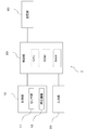
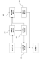
- FIG. 1 is a block diagram illustrating an overall configuration of a blood pressure measurement device 1 according to the present embodiment.
- the blood pressure measurement device 1 generally includes a measurement unit 10, a control unit 20, an input unit 30, and a storage unit 40.
- the blood pressure measurement device 1 may be a stationary device that is used by placing the upper arm of the person to be measured on a fixed base at the time of measurement, or a state in which the movement of the person to be measured at the time of measurement is not constrained It is good also as a wearable apparatus with which it mounts
- the blood pressure measurement device 1 is a wearable device, the movement of the person to be measured is not restrained, but the blood pressure measurement device 1 easily deviates from a state suitable for blood pressure measurement.
- the device according to the present embodiment can obtain the reliability of the measured blood pressure information, the blood pressure information measured in an inappropriate state is the same as the blood pressure information measured in an appropriate state. Since it can prevent handling, it is suitable.
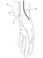
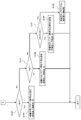
- FIG. 2 is a diagram showing a state in which the measurement unit 10 is attached to the left wrist of the measurement subject by a belt (not shown), and
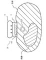
- FIG. 3 is a cross-sectional view schematically showing the structure of the measurement unit 10 and the state at the time of measurement.
- the measurement unit 10 includes a sensor unit 11 and a pressing mechanism 12 for pressing the sensor unit 11 against the wrist, and a radial artery TD that is a blood pressure measurement target exists inside. It arrange
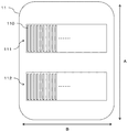
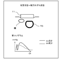
- FIG. 4 is a diagram showing the surface of the sensor unit 11 on the side in contact with the body surface.
- the sensor unit 11 includes a plurality of (for example, 46) pressure sensors arranged in the direction B intersecting the direction A in which the radial artery TD present at the mounting site extends in a state where the measuring unit 10 is mounted.
- 110 has a first sensor array 111 formed by 110 and a second sensor array 112 arranged in parallel therewith.
- the pressure sensors 110 constituting the first and second sensor arrays 111 and 112 are arranged at intervals such that a necessary and sufficient number is arranged on the radial artery TD and the pressure constituting the other sensor array. It arrange
- the pressure sensor 110 a piezoelectric element that measures pressure and converts it into an electrical signal, an element that uses a piezoresistance effect, or the like can be preferably used.
- the pressing mechanism 12 includes, for example, an air bag and a pump that adjusts the internal pressure of the air bag.
- the control unit 20 controls the pump to increase the internal pressure of the air bag
- the pressure sensor 110 is pressed against the body surface by the expansion of the air bag.
- the pressing mechanism 12 may be anything as long as the pressing force on the body surface of the pressure sensor 110 can be adjusted, and is not limited to the one using an air bag.
- the control unit 20 performs various processes such as control of each part of the blood pressure measurement device 1, recording / analysis of measured data, and input / output of data.
- the control unit 20 includes a processor, a ROM (Read Only Memory), a RAM (Random Access Memory), and the like.
- the function of the control unit 20 to be described later is realized by reading and executing a program stored in the ROM or the storage unit 40 by the processor.
- the RAM functions as a work memory when the control unit 20 performs various processes.
- the input unit 30 provides an operation interface to the user.
- operation buttons, switches, touch panels, and the like can be used.
- the storage unit 40 is a storage medium capable of storing and reading data, and includes a program executed by the control unit 20, measurement data obtained from the measurement unit 10, and various data obtained by processing the measurement data. Memorize etc. As the storage unit 40, for example, a flash memory is used.
- the storage unit 40 may be a portable type such as a memory card or may be built in the blood pressure measurement device 1.
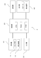
- FIG. 5 is a block diagram illustrating an outline of a functional configuration of the control unit 20.
- the control unit 20 includes a feature amount extraction unit 21, a tonogram creation unit 22, an arrangement state estimation unit 23, a reliability calculation unit 24, and a blood pressure index identification unit 25 as basic functions. ing. In the present embodiment, the functions of these units are exhibited by the control unit 20 executing necessary programs.
- the feature amount extraction unit 21 has a function of extracting the feature amount of the pulse pressure waveform measured by the blood pressure measurement unit for each heartbeat.
- the feature amount extracted in the present embodiment is, for example, a maximum pressure value, a minimum pressure value for each heartbeat, and a difference value between the maximum pressure value and the minimum pressure value.
- the tonogram creation unit 22 is a function for creating a tonogram.
- the tonogram means a distribution shape of feature value values among a plurality of pressure sensors.
- the tonogram in the present embodiment includes a difference value between the maximum pressure value and the minimum pressure value (hereinafter referred to as “ac component”) and a minimum pressure value (hereinafter referred to as “dc component”) extracted by the feature amount extraction unit 21. For each sensor array.
- the arrangement state estimation unit 23 has a function of estimating the arrangement state of the sensor unit 11 with respect to the radial artery TD based on the shape of the tonogram. In the present embodiment, it is finally estimated which of the 64 pattern arrangement states corresponds to.
- the reliability calculation unit 24 is a function that calculates the reliability of the blood pressure information measured by the measurement unit 10 based on the estimated arrangement state of the sensor unit 11.
- the blood pressure index specifying unit 25 has a function of specifying a blood pressure index that becomes a final measurement value from blood pressure information measured by the plurality of pressure sensors 110.
- the blood pressure indexes specified in the present embodiment are systolic blood pressure (SBP), diastolic blood pressure (DBP), and pulse rate (PR).
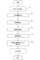
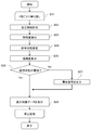
- FIG. 6 is an overall flowchart illustrating an example of a flow of processing performed by the blood pressure measurement device 1 according to the present embodiment.
- the blood pressure measurement device 1 measures blood pressure information for each heartbeat (step S2), extracts a feature amount from the measured information, creates a tonogram (step S3), and the tonogram Based on this, the arrangement state of the sensor unit 11 with respect to the radial artery TD is estimated (step S4), the reliability is calculated based on the estimated arrangement state (step S5), and the reliability and the measured blood pressure information are stored in the storage unit 40 (step S6).
- the control unit 20 controls the pressing mechanism 12 of the measuring unit 10 and maintains the pressing force of the sensor unit 11 in an appropriate state.
- the blood pressure information measured by each pressure sensor 110 is sequentially taken into the control unit 20.
- FIG. 7 shows a pulse pressure waveform (tonometry sensor pressure) measured by the pressure sensor 110.
- the horizontal axis is time, and the vertical axis is blood pressure.
- the sampling frequency is set to 125 Hz, but can be arbitrarily set as long as the shape characteristic of the waveform of one heartbeat can be reproduced.
- the feature quantity extraction unit 21 extracts an ac component and a dc component from the pulse pressure waveform measured by each pressure sensor 110.
- the tonogram creation unit 22 takes the position on the sensor array of each pressure sensor 110 constituting one sensor array on the horizontal axis, and takes the ac component and dc component for each pressure sensor 110 at the same heartbeat on the vertical axis. Create a graph, or tonogram.
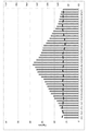
- FIG. 8 shows an example of a tonogram.
- Each pressure sensor 110 is assigned a channel number according to the position where it is arranged.
- the pressure sensor 110 showing the largest ac component value (peak value) for each sensor array is the peak channel
- the pressure sensor 110 showing the smallest ac component value (bottom value) is the bottom channel.
- the tonogram for the first sensor array 111 is referred to as a first tonogram
- the peak value of the first tonogram is referred to as a first peak value
- the bottom value is referred to as a first bottom value
- the tonogram for the second sensor array 112 is referred to as a second tonogram
- the peak value of the second tonogram is referred to as a second peak value
- the bottom value is referred to as a second bottom value.
- the blood pressure index specifying unit 25 selects, as an active channel, a peak channel showing a larger ac component value from among the peak channels of the first sensor array 111 and the second sensor array 112, and the active channel Various blood pressure indices are specified from the measured blood pressure information.
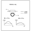
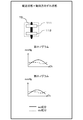
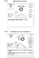
- FIG. 9 is a diagram illustrating a state in which the sensor unit 11 is appropriately disposed with respect to the radial artery TD and a shape of a tonogram in the disposed state.
- FIG. 10, FIG. 11, FIG. 12, FIG. FIG. 16 is a diagram showing seven patterns in which the sensor unit 11 is improperly arranged with respect to the radial artery TD and the shape of the tonogram in the arrangement state.
- an appropriate arrangement state a state in which the first sensor array 111 of the two sensor arrays is disposed at a place most suitable for measuring the pulse pressure wave.
- the ac component of the first tonogram has a mountain shape in which the peak channel is located substantially in the center
- the ac component of the second tonogram has a mountain shape that is slightly flatter than the tonogram of the first sensor array 111.
- the dc component of the 1st sensor array 111 and the 2nd sensor array 112 shows a substantially flat shape, it defines that the sensor part 11 is the state arrange
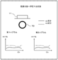
- both the first and second tonograms show a flat shape at a low level for both the ac component and the dc component (the peak value is low and the difference between the peak value and the bottom value is low). Is small), it can be estimated that the degree of force with which the sensor unit 11 is pressed against the radial artery TD is weak, that is, a state where the pressing is insufficient.
- both the first tonogram and the second tonogram show a flat shape at a high level for both the ac component and the dc component (the peak value is high, the peak value and the bottom value are In the case of a small difference), it can be estimated that the degree of force with which the sensor unit 11 is pressed against the radial artery TD is excessive, that is, an overpressed state.
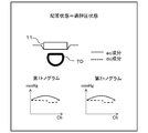
- either the first tonogram or the second tonogram shows a flat shape at a low level for both the ac component and the dc component, and the other tonogram is high for both the ac component and the dc component.
- the sensor unit 11 is inclined in a direction parallel to the extending direction of the radial artery TD (hereinafter referred to as “arterial direction”), that is, in an arterial direction inclined state. Can be estimated.
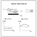
- the dc component of the first tonogram is not flat and has a shape that draws a diagonal line in one direction
- the sensor unit 11 is perpendicular to the direction in which the radial artery TD extends. It can be presumed that the vehicle is inclined in a certain direction (hereinafter referred to as “width direction”), that is, it is in a state of inclination in the width direction.
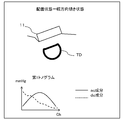
- the sensor unit 11 when the position of the peak channel of the first tonogram is at a position far away from the center to the left and right, the sensor unit 11 is shifted in the width direction, that is, in the width direction shifted state. It can be estimated that there is.
- the sensor unit 11 moves in the arterial direction. It can be estimated that there is a deviation, that is, an arterial direction deviation state.
- the sensor unit 11 when the positions of the peak channels of the first tonogram and the second tonogram are greatly shifted, the sensor unit 11 is shifted in the rotational direction within the contact surface with the body surface, that is, It can be estimated that it is in a state of rotational deviation.
- the arrangement state estimation unit 23 estimates the arrangement state of the sensor unit 11 with respect to the radial artery TD from the feature amount and / or the shape of the tonogram, and the reliability calculation unit 24 calculates the reliability according to the arrangement state.
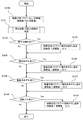
- FIG. 17 is a flowchart illustrating an example of processing when the arrangement state estimation unit 23 estimates the arrangement state of the sensor unit 11.
- 18 and 19 are partial views of a flowchart showing an example of processing in the “depression state / arterial direction inclination determination” stage of FIG. 17, and FIGS. 18 and 19 show one flow.
- FIGS. 17, 18, and 19 show one flow.
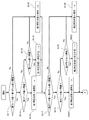
- the placement state estimation unit 23 first determines “depression level / arterial direction inclination” (step S101). As shown in FIGS. 18 and 19, the arrangement state estimation unit 23 estimates the degree of pressing of the first sensor array 111, then estimates the degree of pressing of the second sensor array 112, and then the first sensor array 111 and the first sensor array 111. The “pressed state / arterial direction inclination” of the sensor unit 11 is estimated by a combination of the degree of pressing of the second sensor array 112.
- step S111 it is determined whether or not the difference between the first peak value and the first bottom value exceeds a predetermined output value difference threshold value.
- a predetermined output value difference threshold it is estimated that the degree of pressing on the first sensor array 111 is appropriate (step S112).
- step S111 If the difference between the first peak value and the first bottom value does not exceed the predetermined output value difference threshold value in step S111, it is further determined whether or not the first peak value exceeds the predetermined overpressing level threshold value (S113). ). Here, if the first peak value exceeds the over-pressing level threshold, it is estimated that the degree of pressing to the first sensor array 111 is an over-pressing state (step S114).
- step S113 If it is determined in step S113 that the first peak value does not exceed the overpressing level threshold value, it is further determined whether or not the first bottom value is below a predetermined underpressing level threshold value (S115).
- a predetermined underpressing level threshold value if the first bottom value falls below a predetermined under-pressing level threshold, it is estimated that the degree of pressing of the first sensor array 111 is an under-pressing state (S116). It is estimated that the degree of pressing is appropriate.
- the degree of pressing is estimated as in the case of the first sensor array 111 (steps S117 to S122).
- step S123 it is determined whether or not both the first sensor array 111 and the second sensor array 112 are overpressed.
- the sensor unit 11 estimates that the radial artery TD is in an “overpressed state” and adds the “overpressed state” to the arrangement state flag (S124). ).
- step S123 If it is determined in step S123 that neither the first sensor array 111 nor the second sensor array 112 is overpressed, is both the first sensor array 111 and the second sensor array 112 insufficiently pressed? It is determined whether or not (step S125).
- step S125 when both of the first sensor array 111 and the second sensor array 112 are in an insufficiently pressed state, the sensor unit 11 is estimated to be in an “underpressed state” with respect to the radial artery TD, and is in an arrangement state. A “pressing insufficient state” is added to the flag (step S126).
- step S125 If it is determined in step S125 that neither the first sensor array 111 nor the second sensor array 112 is in an under-pressed state, either the first sensor array 111 or the second sensor array 112 is in an over-pressed state, in addition, it is determined whether or not the other is in a state of insufficient press (step S127).
- the sensor unit 11 performs “arterial direction inclination” with respect to the radial artery TD. It is estimated that the state is “art state”, and “arterial direction inclination state” is added to the arrangement state flag (step S128).
- step S127 If it is determined in step S127 that one of the first sensor array 111 and the second sensor array 112 is in an overpressed state and the other is not in an underpressed state, the sensor unit 11 determines that “appropriate” is applied to the radial artery TD. It is estimated that it is “the arrangement state” (step S129).
- the reliability calculation unit 24 sets the reliability value. Decrease 30.
- the arrangement state estimation unit 23 next determines whether or not the sensor unit 11 has a tilt in the width direction (step S102). Specifically, the value of the dc component indicated by the pressure sensor 110 located in the plus 10 channel from the peak channel of the first sensor array 111 and the pressure sensor 110 located in the minus 10 channel from the peak channel of the first sensor array 111 The “dc component slope” is obtained from the difference between the values of the indicated dc components.
- the placement state estimating unit 23 indicates that the sensor unit 11 is in the “width direction inclined state” with respect to the radial artery TD. It is estimated that there is, and “width direction tilt state” is added to the arrangement state flag (step S103). In addition, the reliability calculation unit 24 subtracts a value of 70/4 from the reliability value.
- the dc component slope may be obtained by using values of two or more points of the tonogram, and is not necessarily limited to that at the position of the pressure sensor 110 in the above channel, and is obtained by linear regression using the values of all channels. May be.
- the arrangement state estimation unit 23 continues to determine whether or not the sensor unit 11 is displaced in the width direction (step S104). Specifically, if the peak channel number of the first sensor array 111 is not within the peak channel position allowable range, it is estimated that the sensor unit 11 is “in the width direction shift state” with respect to the radial artery TD, and the arrangement state The “width direction deviation state” is added to the flag (step S105). In addition, the reliability calculation unit 24 subtracts a value of 70/4 from the reliability value.
- the peak channel position allowable range is, for example, when the sensor array includes 46 pressure sensors 110, the peak channel lower limit threshold is 20 and the peak channel upper limit threshold is 26. can do.
- the method of determining whether or not there is a deviation in the width direction is not limited to the above, and for example, when the ac component of the tonogram has a shape having a plurality of peaks, that is, when the ac component has two or more maximum values. It is also possible to estimate that the state is shifted in the width direction.
- the arrangement state estimation unit 23 continues to determine whether or not the sensor unit 11 has an arterial direction deviation (step S106). Specifically, if the difference between the peak value of the first sensor array 111 and the peak value of the second sensor array 112 falls below a predetermined peak value difference threshold value, the sensor unit 11 detects “arterial direction deviation” with respect to the radial artery TD. The state is estimated, and the “arterial direction deviation state” is added to the arrangement state flag (step S107). Further, the reliability calculation unit 24 subtracts a value of 70/4 from the reliability value.
- the arrangement state estimation unit 23 continues to determine whether the sensor unit 11 has a rotational deviation (step S108). Specifically, when the difference between the peak channel number of the first sensor array 111 and the peak channel number of the second sensor array 112 exceeds a predetermined peak channel difference threshold, the sensor unit 11 performs “ It is estimated that the state is “rotational deviation”, and “rotational deviation state” is added to the arrangement state flag (step S109). Further, the reliability calculation unit 24 subtracts a value of 70/4 from the reliability value.
- the final arrangement state of the sensor unit 11 with respect to the radial artery TD is estimated as one of 64 patterns, and the reliability of the measurement value is calculated according to this, along with the calculated reliability.
- the measured blood pressure information and each specified blood pressure index are recorded in the storage device.
- the blood pressure measurement device 1 According to the present embodiment efficiently arranges the sensor unit 11 from the viewpoint of pressing degree, arterial direction inclination, width direction inclination, arterial direction deviation, width direction deviation, and rotational deviation. Can be estimated. Further, the reliability of the blood pressure information measured by the sensor unit 11 can be obtained from the arrangement state of the sensor unit 11 estimated in this way by a 100-point method. For this reason, the blood pressure information obtained when the sensor unit 11 is in an inappropriate arrangement state (that is, a measurement value with low reliability) is replaced with the blood pressure information obtained when the sensor unit 11 is in an appropriate arrangement state (that is, the reliability level). (High measurement value) can be prevented from being handled in the same manner.
- the reliability value is calculated at each of the five steps for estimating the arrangement state. However, it is not always necessary to use such a method, and the estimation is finally performed. The reliability may be calculated based on the arrangement state.
- the reliability is calculated by the 100-point method, but it is not always necessary to have such a continuous value, and “reliable”, “slightly reliable”, “not very reliable”, “ The degree of reliability may be expressed by a step evaluation such as “almost unreliable” or “unreliable”.
- the final arrangement state is estimated to be one of 64 patterns.
- the present invention is not limited to this, and the arrangement state may be estimated from more patterns.
- the arrangement state may be estimated.
- the final arrangement state may be estimated.
- the “how much” element may be added to estimate the arrangement state more finely.
- the arrangement state may be estimated from fewer determination elements.
- the final arrangement state may be estimated only from “the degree of pressing”, “the presence / absence of displacement in the width direction”, and “the presence / absence of inclination in the width direction”. In this way, it is possible to estimate the arrangement state by using only one sensor array.
- the information recorded in the recording device is not limited to that of the present embodiment, and the tonogram data created by the tonogram creation unit 22 and the information on the arrangement state estimated by the arrangement state estimation unit 23 are also recorded. You may make it do.
- Example 2 A second embodiment according to the present invention will be described below with reference to FIGS. Since the present embodiment is substantially the same as the first embodiment except that the hardware configuration includes the output unit 50, such portions are denoted by the same reference numerals as those in the first embodiment and will not be described in detail. Omitted. Moreover, since there are many parts in common with the processing of the blood pressure measurement device and the function of the control unit 20, detailed description of such parts is omitted.
- FIG. 20 is a block diagram illustrating an overall configuration of the blood pressure measurement device 2 according to the present embodiment.
- the blood pressure measurement device 2 generally includes a measurement unit 10, a control unit 20, an input unit 30, a storage unit 40, and an output unit 50. As described above, the configuration and functions are the same as those in the first embodiment except for the output unit 50.
- the output unit 50 provides an interface for outputting information to the user.
- the output unit 50 includes a liquid crystal display and a speaker, but the present invention is not necessarily limited thereto.
- a display device other than a liquid crystal display, an audio output device other than a speaker, a communication device that performs data communication with other devices, and the like can be used.
- the data communication method in the communication device may be wired or wireless. Moreover, it is also possible to use these in combination.
- FIG. 21 is a block diagram illustrating an outline of a functional configuration of the control unit 20.
- the control unit 20 includes, as basic functions, a feature amount extraction unit 21, a tonogram creation unit 22, an arrangement state estimation unit 23, a reliability calculation unit 24, a blood pressure index specification unit 25, an arrangement state output.
- a processing unit 26 In the present embodiment, the functions of these units are exhibited by the control unit 20 executing necessary programs.
- the configuration other than the arrangement state output processing unit 26 is the same as that of the first embodiment.
- the arrangement state output processing unit 26 is a function for performing processing for outputting according to the arrangement state of the sensor unit 11 estimated by the output unit 50 described later.
- FIG. 22 is an overall flowchart illustrating an example of a flow of processing performed by the blood pressure measurement device 2 according to the present embodiment.
- the blood pressure measurement device 2 measures blood pressure information for each heartbeat (step S22), extracts a feature amount from the measured information, creates a tonogram (step S23), and the tonogram
- the arrangement state of the sensor unit 11 with respect to the radial artery TD is estimated (step S24), and the reliability is calculated based on the estimated arrangement state (step S25).
- the flow up to this point is the same as in the first embodiment.
- the blood pressure measurement device 2 further determines whether or not the estimated arrangement state of the sensor unit 11 is “appropriate” (step S26), and outputs a warning signal from the output unit 50 if it is not “appropriate”. (Step S27).
- the blood pressure measurement device displays each blood pressure index specified by the blood pressure index specifying unit 25, the estimated arrangement state image of the sensor unit 11, the calculated reliability, and a comment corresponding to the estimated arrangement state on the display unit. (Step S28).
- the measurement of blood pressure information, the extraction of the feature amount, the estimation of the arrangement state, and the calculation of the reliability are performed in the same manner as in the first embodiment, and thus the description thereof is omitted.
- the arrangement state output process is performed based on the estimated arrangement state. Processing performed by the unit 26 will be described.
- the arrangement state output processing unit 26 first determines whether or not the estimated arrangement state is “appropriate”. If it is not “appropriate”, processing is performed so that a warning sound is emitted from the speaker as a warning signal. I do. Note that the case where the arrangement state is not appropriate means that the reliability of the measured blood pressure information is equal to or less than a predetermined value. Therefore, whether or not to issue a warning signal is determined by whether the reliability value is the predetermined value. You may make it carry out by whether it exceeds a value.
- the sound may be one type of warning sound or may be a plurality of types of warning sounds according to the arrangement state. Further, a warning according to the arrangement state may be issued by a voice message in a language. In this case, the sound data may be selected from the sound database in the storage unit 40.
- the arrangement state output processing unit 26 performs processing so as to display an “arrangement state image image” corresponding to the estimated arrangement state on the display unit.
- the arrangement state image image may be acquired by selecting the corresponding arrangement state image image data from the arrangement state image image database in the storage unit 40.
- the arrangement state output processing unit 26 performs processing so as to display “arrangement state comments” on the display unit according to the estimated arrangement state. Further, in the arrangement state comment when the arrangement state is not “appropriate”, a “correction instruction comment” that indicates how to correct the arrangement state to an appropriate arrangement state may be displayed together. .
- the arrangement state comment and the correction instruction comment may be acquired by selecting data from the database of the storage unit 40. In this case, comment data including a correction comment in the arrangement state comment may be prepared, and the arrangement state comment and the correction comment may be stored in each database.
- the control unit 20 combines the information processed by the arrangement state output processing unit 26 as described above, the first tonogram created by the tonogram creation unit 22, the reliability calculated by the reliability calculation unit 24, and the blood pressure index.
- Each blood pressure index specified by the specifying unit 25 is displayed on the liquid crystal display.
- FIG. 23A and FIG. 23B show an example of the display screen.
- FIG. 23A is an example when the sensor unit 11 is in an appropriate arrangement state with respect to the radial artery TD
- FIG. 23B is an example when there is a shift and an inclination in the width direction.
- the user of the blood pressure measurement device 2 according to the present embodiment can know the measured blood pressure index (SBP, DBP, PR) and the reliability of the blood pressure index in a timely manner by displaying on the liquid crystal display. it can. In addition, it is possible to know in a timely manner the arrangement of the sensor unit 11 with respect to the radial artery TD to be measured by displaying an image image and character information.
- the user of the blood pressure measurement device 2 when the reliability of the blood pressure information including the blood pressure index is equal to or lower than a predetermined reference value, the user of the blood pressure measurement device 2 according to the present embodiment immediately informs the user by voice and / or a display screen. Can know. Furthermore, the improper arrangement state that causes the reduction in reliability can be known in a timely manner from the image image and the character information, and a method for putting the sensor unit 11 in the appropriate arrangement state is displayed. You can know more. For this reason, the user himself / herself can correct the arrangement state of the sensor unit 11 to a state suitable for measuring blood pressure.
- ⁇ Modification> Various types of information displayed on the display may be recorded in the storage unit 40 as needed in addition to being displayed. Further, not only the displayed information, but also all measured blood pressure information, second tonogram data, and the like may be recorded together.
- information is displayed on a liquid crystal display integrated with the blood pressure measurement device.
- the information is displayed by a portable information terminal such as a monitor, a projector, or a smartphone separate from the blood pressure measurement device by the communication device. May be displayed.
- a warning may be issued by blinking light. In that case, this may be expressed on the screen of the liquid crystal display, or an LED or the like may be used separately from the display.
Landscapes
- Health & Medical Sciences (AREA)
- Life Sciences & Earth Sciences (AREA)
- Engineering & Computer Science (AREA)
- Veterinary Medicine (AREA)
- Surgery (AREA)
- Biophysics (AREA)
- Biomedical Technology (AREA)
- Heart & Thoracic Surgery (AREA)
- Medical Informatics (AREA)
- Molecular Biology (AREA)
- Pathology (AREA)
- Animal Behavior & Ethology (AREA)
- General Health & Medical Sciences (AREA)
- Public Health (AREA)
- Physics & Mathematics (AREA)
- Cardiology (AREA)
- Physiology (AREA)
- Vascular Medicine (AREA)
- Ophthalmology & Optometry (AREA)
- Psychiatry (AREA)
- Signal Processing (AREA)
- Computer Vision & Pattern Recognition (AREA)
- Artificial Intelligence (AREA)
- Dentistry (AREA)
- Computer Networks & Wireless Communication (AREA)
- Nuclear Medicine, Radiotherapy & Molecular Imaging (AREA)
- Radiology & Medical Imaging (AREA)
- Measuring Pulse, Heart Rate, Blood Pressure Or Blood Flow (AREA)
Priority Applications (3)
| Application Number | Priority Date | Filing Date | Title |
|---|---|---|---|
| DE112017004579.7T DE112017004579B4 (de) | 2016-09-12 | 2017-09-05 | Blutdruckmessgerät, Verfahren zum Steuern des Blutdruckmessgerätes und Programm |
| CN201780050407.7A CN109640798B (zh) | 2016-09-12 | 2017-09-05 | 血压测定装置、血压测定装置的控制方法和存储介质 |
| US16/281,212 US11324454B2 (en) | 2016-09-12 | 2019-02-21 | Blood pressure measurement apparatus, method of controlling blood pressure measurement apparatus, and program |
Applications Claiming Priority (2)
| Application Number | Priority Date | Filing Date | Title |
|---|---|---|---|
| JP2016-177704 | 2016-09-12 | ||
| JP2016177704A JP6680155B2 (ja) | 2016-09-12 | 2016-09-12 | 血圧測定装置、血圧測定装置の制御方法およびプログラム |
Related Child Applications (1)
| Application Number | Title | Priority Date | Filing Date |
|---|---|---|---|
| US16/281,212 Continuation US11324454B2 (en) | 2016-09-12 | 2019-02-21 | Blood pressure measurement apparatus, method of controlling blood pressure measurement apparatus, and program |
Publications (1)
| Publication Number | Publication Date |
|---|---|
| WO2018047788A1 true WO2018047788A1 (ja) | 2018-03-15 |
Family
ID=61562641
Family Applications (1)
| Application Number | Title | Priority Date | Filing Date |
|---|---|---|---|
| PCT/JP2017/031862 Ceased WO2018047788A1 (ja) | 2016-09-12 | 2017-09-05 | 血圧測定装置、血圧測定装置の制御方法およびプログラム |
Country Status (5)
| Country | Link |
|---|---|
| US (1) | US11324454B2 (enExample) |
| JP (1) | JP6680155B2 (enExample) |
| CN (1) | CN109640798B (enExample) |
| DE (1) | DE112017004579B4 (enExample) |
| WO (1) | WO2018047788A1 (enExample) |
Cited By (1)
| Publication number | Priority date | Publication date | Assignee | Title |
|---|---|---|---|---|
| JP2018042606A (ja) * | 2016-09-12 | 2018-03-22 | オムロンヘルスケア株式会社 | 血圧測定装置、血圧測定装置の制御方法およびプログラム |
Families Citing this family (7)
| Publication number | Priority date | Publication date | Assignee | Title |
|---|---|---|---|---|
| TWI731339B (zh) | 2018-06-11 | 2021-06-21 | 當代漢雲企業有限公司 | 脈診量測裝置及方法 |
| JP7225893B2 (ja) * | 2019-02-18 | 2023-02-21 | オムロンヘルスケア株式会社 | 血圧値解析支援装置、血圧値解析支援システム、血圧値解析支援方法、およびプログラム |
| JP7127571B2 (ja) | 2019-02-18 | 2022-08-30 | オムロンヘルスケア株式会社 | 血圧レベル変化検出装置、血圧レベル変化検出方法、およびプログラム |
| JP7253419B2 (ja) | 2019-03-25 | 2023-04-06 | オムロンヘルスケア株式会社 | 血圧関連情報表示装置、血圧関連情報表示方法、およびプログラム |
| CN110051336B (zh) * | 2019-04-24 | 2021-12-03 | 京东方科技集团股份有限公司 | 处理生理数据的方法、装置和存储介质 |
| KR102386203B1 (ko) * | 2020-06-03 | 2022-04-13 | (주)참케어 | 혈압 측정을 위한 센서모듈 및 이를 이용한 손목 착용형 휴대용 혈압 측정 장치 |
| US20220022762A1 (en) * | 2020-11-12 | 2022-01-27 | Samsung Electronics Co., Ltd. | Apparatus and method for estimating bio-information |
Citations (4)
| Publication number | Priority date | Publication date | Assignee | Title |
|---|---|---|---|---|
| JPS6234531A (ja) * | 1985-08-08 | 1987-02-14 | コーリン電子株式会社 | 脈波伝播速度測定方法 |
| JP2004113811A (ja) * | 1997-03-25 | 2004-04-15 | Seiko Epson Corp | 圧力検出装置 |
| JP2012223267A (ja) * | 2011-04-18 | 2012-11-15 | Seiko Epson Corp | 超音波測定装置、および超音波測定装置の測定制御方法 |
| JP2014195500A (ja) * | 2013-03-29 | 2014-10-16 | セイコーエプソン株式会社 | 脈拍計及びプログラム |
Family Cites Families (9)
| Publication number | Priority date | Publication date | Assignee | Title |
|---|---|---|---|---|
| JP3495299B2 (ja) * | 1999-12-08 | 2004-02-09 | 日本コーリン株式会社 | 脈波伝播速度情報測定装置および動脈分岐部検出装置 |
| JP3838201B2 (ja) * | 2003-01-21 | 2006-10-25 | オムロンヘルスケア株式会社 | 脈波検出装置 |
| ES2353526T3 (es) * | 2005-06-14 | 2011-03-02 | Microlife Intellectual Property Gmbh | Un dispositivo para medir la presión sanguínea y un método para operar un dispositivo para medir la presión sanguínea. |
| JP5376768B2 (ja) * | 2007-03-30 | 2013-12-25 | シチズンホールディングス株式会社 | 脈波測定装置 |
| CN101366627B (zh) * | 2008-09-26 | 2010-06-23 | 鲁东大学 | 一种能提示血压测量结果可信度的电子血压计 |
| JP5309954B2 (ja) * | 2008-12-17 | 2013-10-09 | オムロンヘルスケア株式会社 | 電子血圧計 |
| ITPI20110127A1 (it) * | 2011-11-08 | 2013-05-09 | W I N Wireless Integrated Network S R L | Struttura di tonometro indossabile |
| US20170323069A1 (en) * | 2016-05-05 | 2017-11-09 | James Stewart Bates | Systems and methods for medical instrument patient measurements |
| JP6680155B2 (ja) * | 2016-09-12 | 2020-04-15 | オムロンヘルスケア株式会社 | 血圧測定装置、血圧測定装置の制御方法およびプログラム |
-
2016
- 2016-09-12 JP JP2016177704A patent/JP6680155B2/ja active Active
-
2017
- 2017-09-05 DE DE112017004579.7T patent/DE112017004579B4/de active Active
- 2017-09-05 CN CN201780050407.7A patent/CN109640798B/zh active Active
- 2017-09-05 WO PCT/JP2017/031862 patent/WO2018047788A1/ja not_active Ceased
-
2019
- 2019-02-21 US US16/281,212 patent/US11324454B2/en active Active
Patent Citations (4)
| Publication number | Priority date | Publication date | Assignee | Title |
|---|---|---|---|---|
| JPS6234531A (ja) * | 1985-08-08 | 1987-02-14 | コーリン電子株式会社 | 脈波伝播速度測定方法 |
| JP2004113811A (ja) * | 1997-03-25 | 2004-04-15 | Seiko Epson Corp | 圧力検出装置 |
| JP2012223267A (ja) * | 2011-04-18 | 2012-11-15 | Seiko Epson Corp | 超音波測定装置、および超音波測定装置の測定制御方法 |
| JP2014195500A (ja) * | 2013-03-29 | 2014-10-16 | セイコーエプソン株式会社 | 脈拍計及びプログラム |
Cited By (1)
| Publication number | Priority date | Publication date | Assignee | Title |
|---|---|---|---|---|
| JP2018042606A (ja) * | 2016-09-12 | 2018-03-22 | オムロンヘルスケア株式会社 | 血圧測定装置、血圧測定装置の制御方法およびプログラム |
Also Published As
| Publication number | Publication date |
|---|---|
| US11324454B2 (en) | 2022-05-10 |
| US20190209096A1 (en) | 2019-07-11 |
| DE112017004579T5 (de) | 2019-06-06 |
| DE112017004579B4 (de) | 2025-10-23 |
| JP6680155B2 (ja) | 2020-04-15 |
| JP2018042606A (ja) | 2018-03-22 |
| CN109640798B (zh) | 2021-07-06 |
| CN109640798A (zh) | 2019-04-16 |
Similar Documents
| Publication | Publication Date | Title |
|---|---|---|
| WO2018047788A1 (ja) | 血圧測定装置、血圧測定装置の制御方法およびプログラム | |
| KR102680411B1 (ko) | 혈압 캘리브레이션 시점 검출 방법 및 장치 | |
| JP6308294B2 (ja) | 脈波伝播時間計測装置および生体状態推定装置 | |
| US11213212B2 (en) | Apparatus for measuring blood pressure, and method for measuring blood pressure by using same | |
| CN109561862B (zh) | 疲劳度判断装置、疲劳度判断方法、疲劳度判断程序以及生物体信息测定装置 | |
| KR20170067131A (ko) | 혈압 측정 장치 및 이를 이용한 혈압 측정 방법 | |
| KR102847308B1 (ko) | 혈압을 측정하는 전자 장치 및 혈압 측정 방법 | |
| JP5376768B2 (ja) | 脈波測定装置 | |
| CN112584763B (zh) | 测定装置 | |
| EP3745952B1 (en) | Electronic device and method of controlling electronic device | |
| CN104027103A (zh) | 生物体信息检测装置以及脉搏计 | |
| JP6339178B2 (ja) | 血圧測定装置 | |
| US20190046050A1 (en) | Pulse wave detector, biological information measurement device, pulse wave detection method and storage medium | |
| JP5942957B2 (ja) | 血圧計 | |
| EP3834715B1 (en) | Apparatus and method for estimating bio-information | |
| JP6766710B2 (ja) | 血圧測定装置、方法及びプログラム | |
| CN102119853B (zh) | 腕式血压监测器 | |
| JP2008237533A (ja) | 脈波測定装置 | |
| EP4108165B1 (en) | Apparatus and method for estimating bio-information | |
| CN113384246A (zh) | 用于估计生物信息的设备 | |
| US20180206736A1 (en) | Blood pressure measurement device and method | |
| JP2016119981A (ja) | 脈波測定装置及び脈波測定方法 | |
| US20170273580A1 (en) | Blood pressure measurement device and method of blood pressure measurement | |
| JP6790936B2 (ja) | 血圧データ処理装置、血圧データ処理方法、およびプログラム | |
| WO2016006250A1 (ja) | 生体情報測定装置 |
Legal Events
| Date | Code | Title | Description |
|---|---|---|---|
| 121 | Ep: the epo has been informed by wipo that ep was designated in this application |
Ref document number: 17848728 Country of ref document: EP Kind code of ref document: A1 |
|
| 122 | Ep: pct application non-entry in european phase |
Ref document number: 17848728 Country of ref document: EP Kind code of ref document: A1 |
|
| WWG | Wipo information: grant in national office |
Ref document number: 112017004579 Country of ref document: DE |