WO2018047713A1 - Hot press device - Google Patents
Hot press device Download PDFInfo
- Publication number
- WO2018047713A1 WO2018047713A1 PCT/JP2017/031446 JP2017031446W WO2018047713A1 WO 2018047713 A1 WO2018047713 A1 WO 2018047713A1 JP 2017031446 W JP2017031446 W JP 2017031446W WO 2018047713 A1 WO2018047713 A1 WO 2018047713A1
- Authority
- WO
- WIPO (PCT)
- Prior art keywords
- heating furnace
- press
- press machine
- heating
- manipulator
- Prior art date
Links
Images


Classifications
-
- B—PERFORMING OPERATIONS; TRANSPORTING
- B21—MECHANICAL METAL-WORKING WITHOUT ESSENTIALLY REMOVING MATERIAL; PUNCHING METAL
- B21D—WORKING OR PROCESSING OF SHEET METAL OR METAL TUBES, RODS OR PROFILES WITHOUT ESSENTIALLY REMOVING MATERIAL; PUNCHING METAL
- B21D22/00—Shaping without cutting, by stamping, spinning, or deep-drawing
- B21D22/20—Deep-drawing
- B21D22/208—Deep-drawing by heating the blank or deep-drawing associated with heat treatment
-
- B—PERFORMING OPERATIONS; TRANSPORTING
- B21—MECHANICAL METAL-WORKING WITHOUT ESSENTIALLY REMOVING MATERIAL; PUNCHING METAL
- B21D—WORKING OR PROCESSING OF SHEET METAL OR METAL TUBES, RODS OR PROFILES WITHOUT ESSENTIALLY REMOVING MATERIAL; PUNCHING METAL
- B21D22/00—Shaping without cutting, by stamping, spinning, or deep-drawing
- B21D22/02—Stamping using rigid devices or tools
- B21D22/022—Stamping using rigid devices or tools by heating the blank or stamping associated with heat treatment
-
- B—PERFORMING OPERATIONS; TRANSPORTING
- B21—MECHANICAL METAL-WORKING WITHOUT ESSENTIALLY REMOVING MATERIAL; PUNCHING METAL
- B21D—WORKING OR PROCESSING OF SHEET METAL OR METAL TUBES, RODS OR PROFILES WITHOUT ESSENTIALLY REMOVING MATERIAL; PUNCHING METAL
- B21D22/00—Shaping without cutting, by stamping, spinning, or deep-drawing
- B21D22/20—Deep-drawing
-
- B—PERFORMING OPERATIONS; TRANSPORTING
- B21—MECHANICAL METAL-WORKING WITHOUT ESSENTIALLY REMOVING MATERIAL; PUNCHING METAL
- B21D—WORKING OR PROCESSING OF SHEET METAL OR METAL TUBES, RODS OR PROFILES WITHOUT ESSENTIALLY REMOVING MATERIAL; PUNCHING METAL
- B21D24/00—Special deep-drawing arrangements in, or in connection with, presses
- B21D24/005—Multi-stage presses
-
- B—PERFORMING OPERATIONS; TRANSPORTING
- B21—MECHANICAL METAL-WORKING WITHOUT ESSENTIALLY REMOVING MATERIAL; PUNCHING METAL
- B21D—WORKING OR PROCESSING OF SHEET METAL OR METAL TUBES, RODS OR PROFILES WITHOUT ESSENTIALLY REMOVING MATERIAL; PUNCHING METAL
- B21D37/00—Tools as parts of machines covered by this subclass
- B21D37/08—Dies with different parts for several steps in a process
-
- B—PERFORMING OPERATIONS; TRANSPORTING
- B21—MECHANICAL METAL-WORKING WITHOUT ESSENTIALLY REMOVING MATERIAL; PUNCHING METAL
- B21D—WORKING OR PROCESSING OF SHEET METAL OR METAL TUBES, RODS OR PROFILES WITHOUT ESSENTIALLY REMOVING MATERIAL; PUNCHING METAL
- B21D37/00—Tools as parts of machines covered by this subclass
- B21D37/16—Heating or cooling
-
- B—PERFORMING OPERATIONS; TRANSPORTING
- B21—MECHANICAL METAL-WORKING WITHOUT ESSENTIALLY REMOVING MATERIAL; PUNCHING METAL
- B21D—WORKING OR PROCESSING OF SHEET METAL OR METAL TUBES, RODS OR PROFILES WITHOUT ESSENTIALLY REMOVING MATERIAL; PUNCHING METAL
- B21D43/00—Feeding, positioning or storing devices combined with, or arranged in, or specially adapted for use in connection with, apparatus for working or processing sheet metal, metal tubes or metal profiles; Associations therewith of cutting devices
- B21D43/02—Advancing work in relation to the stroke of the die or tool
- B21D43/026—Combination of two or more feeding devices provided for in B21D43/04 - B21D43/18
-
- B—PERFORMING OPERATIONS; TRANSPORTING
- B21—MECHANICAL METAL-WORKING WITHOUT ESSENTIALLY REMOVING MATERIAL; PUNCHING METAL
- B21D—WORKING OR PROCESSING OF SHEET METAL OR METAL TUBES, RODS OR PROFILES WITHOUT ESSENTIALLY REMOVING MATERIAL; PUNCHING METAL
- B21D43/00—Feeding, positioning or storing devices combined with, or arranged in, or specially adapted for use in connection with, apparatus for working or processing sheet metal, metal tubes or metal profiles; Associations therewith of cutting devices
- B21D43/02—Advancing work in relation to the stroke of the die or tool
- B21D43/04—Advancing work in relation to the stroke of the die or tool by means in mechanical engagement with the work
- B21D43/05—Advancing work in relation to the stroke of the die or tool by means in mechanical engagement with the work specially adapted for multi-stage presses
-
- B—PERFORMING OPERATIONS; TRANSPORTING
- B21—MECHANICAL METAL-WORKING WITHOUT ESSENTIALLY REMOVING MATERIAL; PUNCHING METAL
- B21D—WORKING OR PROCESSING OF SHEET METAL OR METAL TUBES, RODS OR PROFILES WITHOUT ESSENTIALLY REMOVING MATERIAL; PUNCHING METAL
- B21D43/00—Feeding, positioning or storing devices combined with, or arranged in, or specially adapted for use in connection with, apparatus for working or processing sheet metal, metal tubes or metal profiles; Associations therewith of cutting devices
- B21D43/02—Advancing work in relation to the stroke of the die or tool
- B21D43/04—Advancing work in relation to the stroke of the die or tool by means in mechanical engagement with the work
- B21D43/10—Advancing work in relation to the stroke of the die or tool by means in mechanical engagement with the work by grippers
- B21D43/105—Manipulators, i.e. mechanical arms carrying a gripper element having several degrees of freedom
Definitions
- the present disclosure relates to a hot press apparatus that heats and presses an object to be pressed.
- Patent Document 1 Japanese Patent Application Publication No. 2009-142852 (Patent Document 1) and Japanese Patent Application Publication No. 2009-285728 (Patent Document 2) show a hot press apparatus.
- These hot pressing apparatuses are composed of one heating furnace, one pressing machine, and a conveying apparatus that conveys a press object from the heating furnace to the pressing machine.
- the hot press (it is also called hot press) is implement
- steel sheets that have been hot-pressed with a hot-pressing device are required to have higher strength while ensuring ductility and toughness.
- the present disclosure aims to provide a hot press apparatus that enables the steel sheet to have higher strength, ductility, and toughness at the same time.
- a hot press apparatus for solving the above problems is provided in a transport range by a first press machine, a second press machine, a transport device that connects the first press machine and the second press machine, and a transport range by the transport device.
- a heating furnace A heating furnace.
- the hot pressing apparatus of the present disclosure it is possible to further increase the strength, ductility and toughness of the steel sheet.
- a hot press member having high strength characteristics is used as a collision-resistant component for automobiles.
- This hot-pressed part is required to improve ductility and toughness in order to further increase the strength.
- the present inventors have found that high strength characteristics can be obtained by repeating heating and cooling cycles a plurality of times.
- a conventional hot press apparatus is composed of a single heating furnace, a single press machine having a function of cooling an object to be processed, and a conveying apparatus that conveys the press object from the heating furnace to the press machine. .
- Hot press forming is easier than when forming a high-strength steel sheet cold. For this reason, by using hot press molding, a high-strength molded product can be molded in a single pressing step. Therefore, repeating the heating and cooling cycles a plurality of times is not assumed in the conventional hot press apparatus.
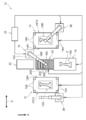
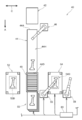
- FIG 1 and 2 are schematic views showing a hot press apparatus 10 according to the present embodiment, and the hot press apparatus 10 includes a press machine 12 and a press machine 14. Between the press machine 12 and the press machine 14 and in the vicinity of the corner of the press machine 14, a first manipulator 16 that is an example of a transport device that connects the press machines 12 and 14 is provided.
- 1st manipulator 16 conveys the material Z comprised with the steel plate, and takes it in / out to each press machine 12 and 14.
- FIG. For this reason, each press machine 12 and 14 is arranged in the conveyance range by the first manipulator 16. Thereby, both the press machines 12 and 14 are connected by the first manipulator 16.
- the first manipulator 16 may be installed on the heating furnace 18.
- the manipulator that handles the material Z entering and exiting the heating furnace may be installed on the heating furnace not only in the first embodiment but also in other embodiments.
- a heating furnace 18 is provided in the conveyance range by the first manipulator 16.
- the heating furnace 18 is disposed between the first press machine 12 and the second press machine 14 and on the back side A of the press machines 12 and 14. Thereby, the material Z is moved between the heating furnace 18 and the press machines 12 and 14 by the first manipulator 16, so that the material Z is transferred between the heating furnace 18 and the press machine 12 and the heating furnace 18. And the press 14.
- the heating furnace 18 is a device that heats the material Z to be heated, and examples of the heating furnace 18 include a high-frequency heating furnace, a resistance heating furnace, a gas heating furnace, and an infrared heating furnace. As shown in FIGS. 1 and 3, the heating furnace 18 includes a lid 18 ⁇ / b> E that opens and closes an entrance / exit 18 ⁇ / b> D. The lid 18E varies the opening height of the doorway 18D to be opened in accordance with the size of the target material Z.
- the heating furnace 18 includes a drive unit 18G that rotationally drives a roller 18F provided therein.
- a drive unit 18G that rotationally drives a roller 18F provided therein.
- an electric heating device may be used instead of the heating furnace.
- the press machine 12 is a hydraulic press machine for press-forming the material Z with a high load.
- the press machine 12 includes four pillars 12A, and the ceiling part 12B is supported by each pillar 12A.
- the press machine 12 is formed in a rectangular shape in plan view, and the material Z is taken in and out from each long side.
- the press machine 12 is not limited to a hydraulic press machine, and may be another type of press machine such as a servo press. The same applies to the presses of the other embodiments.
- a pair of upper mold 12C and lower mold 12D are provided inside each pillar 12A.
- the upper mold 12C is driven in the vertical direction with respect to the lower mold 12D by an elevating mechanism (not shown).
- One of the upper mold 12C and the lower mold 12D is a convex mold (punch), and the other is a concave mold (die) corresponding to the convex mold.
- the material Z arranged in the lower mold 12D is press-molded by the upper mold 12C.
- the material Z is cooled while being sandwiched between the upper mold 12C and the lower mold 12D.
- the upper mold 12C and the lower mold 12D are provided with a refrigerant flow path. The heat lost when the material Z is pressed is released through the refrigerant.
- the press machine 14 is composed of a high-speed forming servo machine and can control the press speed and the like by controlling the servo motor.
- the press machine 14 includes four pillars 14A, and the ceiling part 14B is supported by each pillar 14A. As shown in FIG. 2, the press machine 14 is formed in a rectangular shape in plan view, and the material Z can be taken in and out from each long side.
- a pair of upper mold 14C and lower mold 14D is provided inside each column 14A, and the upper mold 14C is driven in the vertical direction with respect to the lower mold 14D by an elevating mechanism (not shown). Is done.
- One of the upper mold 14C and the lower mold 14D is a convex mold, and the other is a concave mold corresponding to one convex mold.
- the upper mold 14C and the lower mold 14D have the same functions as the upper mold 12C and the lower mold 12D except that the mold shapes are different.
- a conveyance table 20 is provided between the press machines 12 and 14.
- One entrance / exit 12 ⁇ / b> FI which is an example of the entrance of the material Z into the press machine 12, opens to the transport table 20 side.
- one entrance / exit 14FI which is an example of the loading port of the material Z to the press machine 14 opens to the conveyance table 20 side.
- the transport table 20 includes four legs 20A, and the top 20B supported by the legs 20A is formed in a rectangular frame shape (see FIG. 1).
- a plurality of cylindrical rollers 20C extending in the width direction of the top portion 20B are arranged in the length direction of the top portion 20B.
- Each roller 20C is connected to the drive unit 20D and can be driven to rotate.
- Each roller 20 ⁇ / b> C of the transport table 20 is disposed at the same height as the roller 18 ⁇ / b> F in the heating furnace 18 provided on one end side of the transport table 20. Thereby, the conveyance table 20 and the heating furnace 18 move the material Z between the heating furnace 18 and the conveyance table 20 by moving on each roller 20C, 20F.
- a material table 22 is provided on the other end side of the transfer table 20.
- a first manipulator 16 is disposed between the material table 22 and the press machine 14.
- the first manipulator 16 includes a turntable 16A, an articulated arm 16B rotatably supported on the turntable 16A, and a holding tool 16C attached to the tip of the arm 16B in a replaceable manner.
- the material table 22, the conveyance table 20, the press machine 12, the press machine 14, and the heating furnace 18 are provided within the movement range of the material Z by the holding tool 16C.
- the holding tool 16C includes an adsorption-type holding mechanism that adsorbs and holds the material Z and a hook-type holding mechanism that holds and holds the material Z. Instead of the hook-type holding mechanism, a holding type holding mechanism that holds and holds may be used.
- the first manipulator 16 is connected to a controller 24 composed of an industrial computer or the like.
- the controller 24 is also connected to the press machines 12 and 14, the heating furnace 18, and the transfer table 20.
- the first manipulator 16, the press machines 12, 14, the heating furnace 18, and the transfer table 20 operate according to instructions from the control signal output from the controller 24.
- a second manipulator 26 similar to the first manipulator 16 is provided in the vicinity of the corner of the press machine 12.
- a controller 24 is also connected to the second manipulator 26, and the second manipulator 26 operates in accordance with an instruction by a control signal from the controller 24.
- the second manipulator 26 discharges the material Z pressed by the press machine 12 from the other inlet / outlet 12FO and loads it on a linear conveyance machine (not shown), and conveys the material Z to the next process at a high speed by the linear conveyance machine.
- a third manipulator 28 similar to the first manipulator 16 is provided in the vicinity of the corner of the press machine 14.
- a controller 24 is also connected to the third manipulator 28, and the third manipulator 28 also operates according to an instruction by a control signal from the controller 24.
- the third manipulator 28 can discharge the material Z pressed by the pressing machine 14 from the other inlet / outlet port 14FO and load it on a linear conveyance machine (not shown), and can convey the material Z to the next process at a high speed by the linear conveyance machine.
- the first manipulator 16 is described as an example of the transport device, but the present invention is not limited to this.
- you may comprise a conveying apparatus with a conveyor.
- a transport apparatus is configured with a plurality of manipulators, conveyors, or the like, if transport paths by a plurality of manipulators, linear transport machines, and conveyors overlap or are connected, they are regarded as one transport apparatus.
- the conveyance paths by a plurality of manipulators, linear conveyance machines, and conveyors are not overlapped or connected, they are regarded as different conveyance devices. The same applies to the following embodiments.
- the convey route that constitutes the convey range is assumed to constitute the convey route.
- the movable range of the holding tool 16C of the robot hand or manipulator is used as the transport path.
- the conveyor and the movable range of the holding tool 16C of a manipulator be a conveyance path
- the controller 24 operates according to a program stored in a built-in storage medium, and outputs control signals to the manipulators 26 and 28, the press machines 12 and 14, the heating furnace 18, and the transfer table 20.
- the manipulators 26 and 28, the press machines 12 and 14, the heating furnace 18, and the transfer table 20 operate according to control signals from the controller 24.
- the material Z (blank) is previously loaded on the material table 22.
- the controller 24 starts the operation according to the stored program and outputs a control signal to the first manipulator 16
- the first manipulator 16 uses the holding tool 16C of the suction-type holding mechanism to load the material Z loaded on the material table 22. (Blank) is held and conveyed to the conveyance table 20.
- the controller 24 outputs a control signal to the heating furnace 18 and the transfer table 20.
- the heating furnace 18 opens the lid 18E and adjusts the opening height while opening the lid 18E according to the size of the material Z (blank) to be heated.
- the drive unit 20D of the transport table 20 rotates the roller 20C and the drive unit 18G of the heating furnace 18 rotates the roller 18F.
- the drive part 20D of the conveyance table 20 and the roller 18F of the heating furnace 18 accommodate the material Z (blank) in the heating furnace 18 by roller driving.
- the material Z (blank) of the transfer table 20 is accommodated in the heating furnace 18 by the roller 20C of the transfer table 20 and the roller 18F of the heating furnace 18.
- the transfer table 20 constitutes a housing device for the heating furnace 18, and the transfer table 20 can be regarded as a part of the heating furnace 18.
- the heating furnace 18 heats the material Z (blank) at a set temperature (for example, about 1000 ° C.) for a set time (for example, 4 minutes) in accordance with a control signal from the controller 24. Thereafter, the material Z (blank) heated by the roller driving of the roller 20 ⁇ / b> C of the conveyance table 20 and the roller 18 ⁇ / b> F of the heating furnace 18 is discharged to the conveyance table 20.
- a set temperature for example, about 1000 ° C.
- a set time for example, 4 minutes
- the roller 20 ⁇ / b> C of the transfer table 20 and the roller 18 ⁇ / b> F of the heating furnace 18 are the first arrangement position 18 ⁇ / b> A located in the heating furnace 18 and the second arrangement position located in the conveyance range outside the heating furnace 18.
- a conveying mechanism for moving the material Z in the reciprocating direction with respect to 20E is configured.
- the first manipulator 16 can directly convey the material Z between at least one of the press machines 12 and 14 and the second arrangement position 20E.
- the first manipulator 16 which is a transport device has a transport function of transporting the material Z from at least one of the press machines 12 and 14 to the heating furnace 18.
- the direct conveyance means that the material Z is not handed over or transferred, or a detour that stops at another place in the middle of conveyance.
- the first manipulator 16 can directly convey the material Z between each of the press machines 12 and 14 and the second arrangement position 20E.
- the first manipulator 16 directly conveys the material Z between the press machines 12 and 14 that are a plurality of press machines and the second arrangement position 20E.
- the taking-in / out time of the material Z (blank) from the heating furnace 18 is within 2 seconds (conveying speed 750 mm / s or more) with the material Z having a length of 1.5 m in the heating furnace charging direction (hereinafter referred to as charging direction). To do.
- the material Z (blank after heating) discharged to the transfer table 20 is held and lifted up by the holding tool 16C exchanged with the hook-type holding mechanism of the first manipulator 16 controlled by the controller 24. Then, the first manipulator 16 controlled by the controller 24 conveys the lifted material Z (blank after heating) to the press machine 12 and sets it in the lower mold 12D of the press machine 12.
- the press machine 12 descends the upper mold 12C according to an instruction from the controller 24, and press-molds the material Z (blank after heating) between the upper mold 12C and the lower mold 12D. At this time, the heat of the material Z (blank after heating) is rapidly taken away by the upper mold 12C and the lower mold 12D. In particular, the amount of heat removed while the mold reaches the bottom dead center and the material Z is held between the upper mold 12C and the lower mold 12D is large. This is the first hot press molding.
- the time is about 8 seconds, for example.
- the material Z (blank after heating) discharged to the transfer table 20 is set in the press machine 12 by the first manipulator 16, but the present invention is not limited to this.
- a linear conveyor (not shown) is provided between the conveyor table 20 and the press machine 12, and the material Z (blank after heating) discharged from the heating furnace 18 to the conveyor table 20 is lifted up by the first manipulator 16, It may be set on the press machine 12 at a high speed with a linear conveyance machine to increase the speed and reduce the time.
- the material Z (blank after heating) is continuously pressed and held and cooled by the press machine 12 for a predetermined press time (for example, 10 seconds), and then the upper mold 12C is raised and the press machine 12 is opened.
- a lift-up mechanism (not shown) of the press machine 12 lifts and releases the pressed material Z (intermediate product) from the lower mold 12D.
- the first manipulator 16 that has received an instruction from the controller 24 conveys the material Z (intermediate product) pressed by the holding tool 16 ⁇ / b> C of the hook-type holding mechanism to the transfer table 20.
- the material Z (intermediate product) transported to the transport table 20 is accommodated in the heating furnace 18 again by driving the roller according to an instruction from the controller 24.
- the heating furnace 18 reheats the material Z (intermediate product) accommodated in accordance with an instruction from the controller 24, reaches a reheating temperature (eg, 900 ° C.), and then reaches a material Z (intermediate time) for a predetermined time (eg, 2 minutes). Product) at the reheating temperature. Thereafter, the heating furnace 18 discharges the material Z (heating intermediate product) to the transport table 20 by the roller driving described above.
- a reheating temperature eg, 900 ° C.
- a material Z (intermediate time) for a predetermined time eg, 2 minutes.
- the loading / unloading time of the material Z (heating intermediate product) from the heating furnace 18 is within about 2 seconds (conveying speed of 750 mm / s or more) for a material having a length of 1.5 m in the charging direction.
- the material Z (heated intermediate product) discharged to the transfer table 20 is held by the holding tool 16C of the hook type holding mechanism of the first manipulator 16 controlled by the controller 24.
- the controller 24 calculates the hook position by the hook-type holding mechanism in consideration of the thermal expansion of the material Z (heating intermediate product), and outputs a control signal to the first manipulator 16.
- the first manipulator 16 transports the material Z (heated intermediate product) held and lifted by the holding tool 16C of the hook-type holding mechanism to the press machine 14 and sets it in the lower mold 14D of the press machine 14 To do.
- the press machine 14 descends the upper mold 14C according to an instruction from the controller 24, and press-molds the material Z (heating intermediate product) between the upper mold 14C and the lower mold 14D. At this time, the heat of the material Z (heating intermediate product) is rapidly taken away by the upper mold 14C and the lower mold 14D. In particular, the amount of heat removed while the mold reaches the bottom dead center and the material Z is held between the upper mold 14C and the lower mold 14D is large. This is the second hot press molding.
- the time is about 8 seconds, for example.
- the material Z (heated intermediate product) discharged to the transfer table 20 is set in the press machine 14 by the first manipulator 16, but the present invention is not limited to this.
- a linear conveyance machine (not shown) between the conveyance table 20 and the press machine 14 and lifting up the material Z (heating intermediate product) discharged from the heating furnace 18 to the conveyance table 20 with the first manipulator 16
- It may be set on the press machine 14 at a high speed by a linear conveyor to increase the speed and reduce the time.
- the mold of the press machine 14 has a mold shape adapted to the final product size considering the thermal expansion of the material Z (heating intermediate product).
- the pressing machine 14 continuously presses and holds the material Z (heating intermediate product) for a predetermined pressing time (for example, 15 seconds), then raises the upper die 14C and opens the pressing machine 14.
- the pressed material Z (molded product) is lifted and released from the lower mold 14D by a lift-up mechanism (not shown) of the press machine 14.
- the 3rd manipulator 28 which received the instruction
- the cycle time is about 7 minutes / part for the two heating times and the conveying time.
- the heat history control can be performed by hot pressing the material Z to be pressed a plurality of times (twice in the present embodiment).
- an ultra-high-strength hot press-molded product having improved toughness by quenching by hot pressing multiple times can be obtained.
- the material Z to be pressed in the first hot pressing, is austenitized to achieve complete solid solution of the carbide, and then undergo phase transformation (martensitic transformation or bainite transformation) to the hard phase. For this reason, compared with the case where the material Z to be pressed is converted to ferrite pearlite, it is possible to form the material Z (intermediate product) pressed with a small austenite particle size.
- austenite grain size can be refined by heating in the second hot press, and then martensitic transformation can be generated from the fine austenite grain size. A strong hot press-formed product can be obtained.
- the hot press device 10 can be reduced in size and space can be saved.
- the heat treatment can be performed a plurality of times by arranging the two press machines 12 and 14 and the one heating furnace 18 so as to surround the conveyance area where the material Z is conveyed. For this reason, the heating furnace 18 can be shared by the first heat treatment and the second heat treatment, and the heating furnace 18 can be effectively used.
- the heating time of the first heat treatment and the heating time of the second heat treatment in the heating furnace 18 can be individually set.
- the process of holding the material Z at a predetermined temperature for a certain time during the first heat treatment and discharging the heated material Z without holding it during the second heat treatment can be handled. .
- the molds for different parts using steel plates of the same type and thickness are installed in the press machines 12, 14, and the steel plates for each part are alternately heated and distributed to the press machines 12, 14 for hot pressing. As a result, two parts can be manufactured on the same line.
- the cold press since the cold press does not require heating time, it can be used for mass production.
- a pre-molding method in which hot pressing is performed after cold forming is also possible.
- the first heat treatment and the second heat treatment are alternate, but the inside of the furnace is multi-staged according to the ratio of the first heat time and the second heat time. By doing so, time loss can be eliminated. That is, by sequentially storing materials at a certain time during the first heat treatment, the heating furnace 18 is continuously operated if the second heating is started in an empty stage immediately after unloading after the first heating. be able to.
- FIG. 4 is a diagram illustrating the second embodiment.
- the same or equivalent parts as those in the first embodiment are denoted by the same reference numerals, and the description thereof is omitted.
- the transport table 20 is abolished compared to the first embodiment.
- the heating furnace 18 includes a transport mechanism 32 capable of forming a retracted state 18C disposed inside the heating furnace 18 and a discharge state 18B extending from the entrance to the outside of the heating furnace 18.
- the transport mechanism 32 is disposed in front of the entrances 12FI and 14FI, which are examples of the entrances of the press machine 12 and the press machine 14, in the transport range by the first manipulator 16 in the discharge state 18B.
- the conveyance mechanism 32 moves the material Z between the first arrangement position 32A located in the heating furnace 18 and the second arrangement position 32B located outside the heating furnace and located in the conveyance range. .
- controller 24 outputs to the first manipulator 16 an instruction to take out the pressed material Z from the press machine 12 and convey it to the conveyance mechanism 32 in the discharge state 18B, that is, the second arrangement position 32B.
- the heating furnace 18 places the transport mechanism 32 in the retracted state 18C, thereby transporting the mechanism 32.
- the upper material Z can be quickly heated.
- the heating furnace 18 sets the transport mechanism 32 to the discharge state 18B, so that the heated material Z on the transport mechanism 32 can be quickly placed in the transport range by the first manipulator 16. As a result, the exchange of the material Z with the heating furnace 18 can be simplified and performed smoothly.
- the conveyance mechanism 32 is arrange
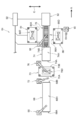
- FIG. 5 is a view showing the hot press device 36 of the present embodiment.
- the same or equivalent parts as those of the first embodiment are denoted by the same reference numerals, description thereof is omitted, and only different parts are described.
- the hot press device 36 of the present embodiment is provided with a second heating furnace 38 in addition to the heating furnace 18 (referred to as the first heating furnace 18 in the present embodiment). to differ greatly.
- the first heating furnace 18 is provided on one end side of the transfer table 20, and the second heating furnace 38 is provided on the other end side.
- the number of heating furnaces is two or more and the number of the press machines 12 and 14 or less.
- the material table 22 is disposed on the side of the second heating furnace 38 on the press machine 14 side, and the first manipulator 16 is disposed between the first heating furnace 18 and the press machine 14. Further, the press machines 12 and 14, the heating furnaces 18 and 38, and the tables 20 and 22 are provided in a conveyance range by the first manipulator 16.
- the first manipulator 16 holds the material Z (blank) loaded on the material table 22 by the suction-type holding mechanism and transfers it to the transfer table 20.
- the material Z (blank) conveyed to the conveyance table 20 is accommodated in the first heating furnace 18 by the roller driving described above.
- the first heating furnace 18 heats the material Z (blank) at a set temperature (for example, about 900 ° C.) for a set time (for example, 4 minutes), and then discharges the material Z (blank) to the transport table 20 by roller driving. .
- the material Z (blank after heating) discharged to the conveying table 20 is held and lifted up by the hook-type holding mechanism of the first manipulator 16, and is set in the lower mold 12D of the press machine 12.
- the press machine 12 lowers the upper mold 12C and press-molds the material Z (blank after heating) between the upper mold 12C and the lower mold 12D. At this time, the heat of the material Z (blank after heating) is rapidly taken away by the upper mold 12C and the lower mold 12D. In particular, the amount of heat removed while the mold reaches the bottom dead center and the material Z is held between the upper mold 12C and the lower mold 12D is large. This is the first hot press molding.
- the time from when the material Z (blank after heating) is discharged from the first heating furnace 18 to being held between the upper mold 12C and the lower mold 12D is managed.
- the time is about 8 seconds, for example.
- the material Z (blank after heating) discharged to the transfer table 20 is set in the press machine 12 by the first manipulator 16, but the present invention is not limited to this.
- a linear conveyance machine (not shown) is provided between the conveyance table 20 and the press machine 12, and the material Z (blank after heating) discharged from the first heating furnace 18 to the conveyance table 20 is pressed at a high speed by the linear conveyance machine. It may be set to 12 for speeding up and time reduction.
- the pressing machine 12 continuously presses and holds the material Z (blank after heating) for a predetermined pressing time (for example, 10 seconds), then raises the upper die 12C and opens the pressing machine 12.
- the pressed material Z (intermediate product) is lifted and released from the lower mold 12D by a lift-up mechanism (not shown) of the press machine 12.
- the first manipulator 16 lifts the material Z (intermediate product) pressed by the hook-type holding mechanism from the lower mold 12D and transports it to the transport table 20.
- the material Z (intermediate product) transported to the transport table 20 is accommodated in the second heating furnace 38 by driving the rollers of the transport table 20.
- the second heating furnace 38 reheats the contained material Z (intermediate product), and when it reaches a reheating temperature (eg, 400 ° C.), the material (intermediate product) is reheated at a reheating temperature for a predetermined time (eg, 60 minutes). After the holding, the material Z (heating intermediate product) is discharged to the transport table 20 by the roller driving described above.
- a reheating temperature eg, 400 ° C.
- the loading / unloading time of the material Z (heating intermediate product) from the second heating furnace 38 is set to be within about 2 seconds (conveying speed of 750 mm / s or more) with a material having a length of 1.5 m in the charging direction.
- the material Z (heated intermediate product) discharged to the transfer table 20 is held by the hook-type holding mechanism of the first manipulator 16.
- the controller 24 calculates the hook position by the hook-type holding mechanism in consideration of the thermal expansion of the material Z (heating intermediate product), and outputs a control signal to the first manipulator 16. Then, the first manipulator 16 sets the lifted-up material Z (heating intermediate product) in the lower mold 14D of the press machine 14.
- the press machine 14 lowers the upper mold 14C and press-molds the material Z (heating intermediate product) between the upper mold 14C and the lower mold 14D. At this time, the heat of the material Z (heating intermediate product) is rapidly taken away by the upper mold 14C and the lower mold 14D. The amount of heat removed while holding the material Z between the upper mold 14C and the lower mold 14D is large. This is the second hot press molding.
- the time from when the material Z (heating intermediate product) is discharged from the second heating furnace 38 to be held between the upper mold 14C and the lower mold 14D is managed.
- the time is about 6 seconds, for example.
- the material Z (heated intermediate product) discharged to the transfer table 20 is set in the press machine 14 by the first manipulator 16, but the present invention is not limited to this.
- a linear conveyance machine (not shown) is provided between the conveyance table 20 and the press machine 14, and the material Z (heated intermediate product) discharged from the second heating furnace 38 to the conveyance table 20 is pressed at a high speed by the linear conveyance machine. 14 may be set to speed up and shorten the time.
- the material Z (heating intermediate product) is continuously pressed and held and cooled by the press machine 14 for a predetermined press time (for example, 15 seconds), and then the upper die 14C is raised and the press machine 14 is opened.
- the pressed material Z (molded product) is lifted and released from the lower mold 14D by a lift-up mechanism (not shown) of the press machine 14.
- the third manipulator 28 lifts up the material Z (molded product) from the lower mold 14D and carries it out to the next step.
- the cycle time takes about 65 minutes per part for the two heating times and the conveying time.
- a first heating furnace 18 that heats the material Z pressed by the press machine 12 and a second heating furnace 38 that heats the material Z pressed by the press machine 14 are provided.
- the material Z can be heated in a dedicated furnace in the second hot press molding and the second hot press molding. For this reason, optimum temperature management is possible in each hot press molding, and quality control of the molded product becomes easy.
- the second heating time is longer than the first heating time, and the unused time of the first heating furnace 18 is generated.
- the second heating furnace 38 may be multistage or a revolving type.
- the second heating furnace 38 it is possible to heat the number of materials Z corresponding to the ratio of the heating time of the second time to the first time (in this embodiment, 15 sheets from 60 minutes / 4 minutes). In the first heating and the second heating, it is possible to synchronize the heating time and minimize the unused time.
- the number of heating furnace stages or the length of the revolving furnace may be set to N times.
- first and second heating furnaces 18 and 38 are provided, a plurality of parts using materials Z of different thicknesses having different heating conditions can be manufactured at the same time.
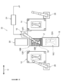
- FIG. 6 is a view showing the hot press device 40 according to the present embodiment, and a material table 42 is provided on the upstream side in the transport direction of the material Z to be processed.
- a continuous roller hearth heating furnace 44 which is an example of a heating furnace and constitutes a part of the transport apparatus, is provided.
- a first manipulator 46 which is an example of a transport device that transports the material Z on the material table 42 to the loading port 44A of the continuous roller hearth heating furnace 44, is provided. ing.
- the continuous roller hearth heating furnace 44 includes a roller 44F that conveys the material Z inserted from the loading port 44A toward the discharge port 44D.
- the continuous roller hearth heating furnace 44 heats the material Z while feeding the material Z from the upstream side to the downstream side by the roller 44F.
- the continuous roller hearth heating furnace 44 has an in-furnace transport section 44H that transports the material Z from the loading port 44A to the discharge port 44D.
- a conveyance table 48 is provided on the downstream side of the continuous roller hearth heating furnace 44, and the material Z discharged from the discharge port 44 ⁇ / b> D of the continuous roller hearth heating furnace 44 can be placed.
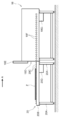
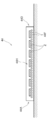
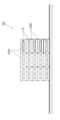
- a multistage heating furnace 50 is provided downstream of the transfer table 48. As shown in FIG. 8, the multistage heating furnace 50 is provided with a plurality of heating chambers 50A arranged in the vertical direction. Each heating chamber 50 ⁇ / b> A can be raised and lowered, and the entrance and exit of each heating chamber 50 ⁇ / b> A can be raised and lowered in accordance with the transfer table 48. Thereby, the charging / discharging operation of the material Z can be performed at the same time at any stage.
- the heating time of the material Z can be controlled by heating the plurality of materials Z in each heating chamber 50A and adjusting the time from the accommodation to the removal in the heating chamber 50A.
- this multistage heating furnace 50 was shown with the broken line in FIG. 8, it shall be able to arrange
- a press machine 52 is disposed on one side with the conveyance table 48 as a boundary, and a press machine 54 is disposed on the other side.
- a second manipulator 56 that connects the continuous roller hearth heating furnace 44, the transport table 48, the press machine 52, the press machine 54, and the multistage heating furnace 50 is provided in the vicinity of the corner of the press machine 54 on the transport table 48 side. ing.
- the discharge port 44 ⁇ / b> D of the continuous roller hearth heating furnace 44, the transfer table 48, the press machine 52, the press machine 54, and the multistage heating furnace 50 are arranged in the transfer range of the material Z by the second manipulator 56.
- the press machines 52 and 54, the continuous roller hearth heating furnace 44, and the multistage heating furnace 50 are arranged so as to surround the transfer table 48.
- the press machine 52 and the press machine 54 face each other.
- the continuous roller hearth heating furnace 44 and the multistage heating furnace 50 are opposed to each other. Thereby, the material Z can be moved between the continuous roller hearth heating furnace 44 and the press machine 52 and between the multistage heating furnace 50 and the press machine 54 by the second manipulator 56.
- a third manipulator 58 is provided in the vicinity of the corner on the opposite side of the conveyance table 48 of the press machine 54, and the third manipulator 58 discharges the material Z pressed by the press machine 54.
- each press 52,54, and each manipulator 46,56,58 is the same as that of 1st Embodiment.
- each manipulator 46, 56, 58, each press machine 52, 54, each heating furnace 44, 50, etc. shall operate
- the first manipulator 46 holds the material Z (blank) loaded on the material table 42 with an adsorption-type holding mechanism, and conveys it to the inlet 44A of the continuous roller hearth heating furnace 44 at regular intervals.
- This material Z (blank) is heated while moving in the continuous roller hearth heating furnace 44 by driving a roller, and a predetermined time (4 minutes as an example) has elapsed since reaching a predetermined temperature (1000 ° C. as an example). Thereafter, the sheet is discharged from the discharge port 44D to the transfer table 48.
- the material Z (blank after heating) discharged to the transport table 48 is held and lifted up by the hook-type holding mechanism of the second manipulator 56 and set in the lower mold 52D of the press machine 52.
- the press machine 52 lowers the upper mold and press-molds the material Z (blank after heating) between the upper mold and the lower mold 52D. At this time, the heat of the material Z (blank after heating) is rapidly taken away by the upper mold and the lower mold 52D. In particular, the amount of heat removed while the mold reaches the bottom dead center and the material Z is held between the upper mold 52C and the lower mold 52D is large. This is the first hot press.
- the time from when the material Z (blank after heating) is discharged from the continuous roller hearth heating furnace 44 to be held between the upper mold 12C and the lower mold 12D is managed.
- the time is about 8 seconds, for example.
- the material Z (blank after heating) discharged to the transfer table 48 is set in the press machine 52 by the second manipulator 56, but the present invention is not limited to this.
- a linear conveyor (not shown) is provided between the conveyor table 48 and the press machine 52, and the material Z (blank after heating) discharged from the continuous roller hearth heating furnace 44 to the conveyor table 48 is pressed at a high speed by the linear conveyor. It may be set in the machine 52 to speed up and shorten the time.
- the pressing machine 52 continuously presses the material Z (blank after heating) for a predetermined pressing time (for example, 10 seconds) and holds and cools it, then raises the upper die and opens the pressing machine 52.
- the pressed material Z (intermediate product) is lifted and released from the lower mold 52D by a lift-up mechanism (not shown) of the press machine 52.
- the second manipulator 56 lifts up the material Z (intermediate product) pressed by the hook-type holding mechanism from the lower mold 52D and transports it to the transport table 48.
- the material Z (intermediate product) transported to the transport table 48 is accommodated in the selected heating chamber 50 ⁇ / b> A of the multistage heating furnace 50 by driving the rollers of the transport table 48.
- the accommodation operation is performed by the second manipulator 56.
- the contained material Z (intermediate product) is reheated, and when the reheating temperature (eg, 900 ° C.) is reached, the material Z (intermediate product) is kept at the reheating temperature for a predetermined time (eg, 2 minutes). After the holding, the material Z (heating intermediate product) is discharged to the transport table 48 by the roller driving described above. At this time, if it cannot be directly discharged by the transfer table 48, the discharge operation is performed by the second manipulator 56.
- the reheating temperature eg, 900 ° C.
- the taking-in / out time of the material Z (heating intermediate product) from the multistage heating furnace 50 shall be within about 2 seconds (conveying speed of 750 mm / s or more) with a material having a length of 1.5 m in the charging direction.
- the material Z (heated intermediate product) discharged to the transfer table 48 is held by the hook-type holding mechanism of the second manipulator 56.
- the controller 60 calculates the hook position by the hook-type holding mechanism in consideration of the thermal expansion of the material Z (heating intermediate product), and outputs a control signal to the second manipulator 56.
- the second manipulator 56 sets the lifted-up material Z (heating intermediate product) in the lower mold 54D of the press machine 54.
- the press machine 54 lowers the upper die and press-molds the material Z (heating intermediate product) between the upper die and the lower die 54D. At this time, the heat of the material Z (heating intermediate product) is rapidly taken away by the upper mold and the lower mold 54D. In particular, the amount of heat removed while the mold reaches the bottom dead center and the material Z is held between the upper mold and the lower mold 54D is large. This is the second hot press molding.
- the time from when the material Z (heating intermediate product) is discharged from the multistage heating furnace 50 until it is held between the upper mold and the lower mold 54D is managed.
- the time is about 6 seconds, for example.
- the material Z (heated intermediate product) discharged to the transfer table 48 is set in the press machine 54 by the second manipulator 56, but the present invention is not limited to this.
- a linear conveyance machine (not shown) is provided between the conveyance table 48 and the press machine 54, and the material Z (heated intermediate product) discharged from the multistage heating furnace 50 to the conveyance table 48 is pressed at a high speed by the linear conveyance machine. It is possible to increase the speed and reduce the time by setting to.
- the material Z (heating intermediate product) is continuously pressed by the press machine 54 for a predetermined press time (for example, 15 seconds), held and cooled, and then the upper die is raised and the press machine 54 is opened.
- the pressed material Z (molded product) is lifted up and released from the lower mold 54D by a lift-up mechanism (not shown) of the press machine 54.
- the third manipulator 58 lifts up the material Z (molded product) from the lower die 54D and delivers it to the next process.
- the first heating time by the continuous roller hearth heating furnace 44 is twice as long as the second heating time by the multistage heating furnace 50. Therefore, in order to synchronize the processing amount, the continuous roller hearth heating furnace The number of in-furnace 44 may be about twice that of the multistage heating furnace 50.
- the material Z is held for a predetermined time after reaching a predetermined temperature, while during the second heating, the material Z is discharged without being held for a predetermined time after reaching the predetermined temperature. Even a pattern can be executed efficiently and is suitable for such production.
- FIG. 9 is a diagram showing a hot press device 64 according to the present embodiment.
- a first manipulator 66 which is an example of a transport device, is provided on the upstream side in the transport direction of the material Z to be processed.
- the side portion of the first manipulator 66 is an example of a heating furnace, and is a part of the transport device.
- the continuous roller hearth heating furnace 68 which comprises a part is provided.
- a press machine 70 is provided on the downstream side of the continuous roller hearth heating furnace 68, and an inlet 70 ⁇ / b> A of the press machine 70 is disposed so as to face the discharge port 68 ⁇ / b> B of the continuous roller hearth heating furnace 68.
- a second manipulator that is an example of a conveying device that connects the continuous roller hearth heating furnace 68 and the press machine 70 between the continuous roller hearth heating furnace 68 and the press machine 70 at the side of the continuous roller hearth heating furnace 68. 72 is provided.
- the discharge port 68 ⁇ / b> B of the continuous roller hearth heating furnace 68 and the charging port 70 ⁇ / b> A of the press machine 70 are provided in the conveyance range of the material Z by the second manipulator 72.
- the continuous roller hearth heating furnace 68 is configured in the same manner as in the fourth embodiment, and conveys the material Z charged from the charging port 68A to the discharge port 68B while sequentially heating it. Thereby, in the continuous roller hearth heating furnace 68, the roller feeding mechanism forms the in-furnace transport section 68H that transports the material Z from the loading port 68A to the discharge port 68B, and forms a part of the transport path.
- a roller hearth heating furnace 74 which is an example of a heating furnace and constitutes a part of the conveying device, is provided on the downstream side of the press machine 70.
- the outlet 70B of the press machine 70 and the roller hearth heating furnace 74 are installed.
- the entrance 74A is disposed to face the entrance 74A.
- the roller hearth heating furnace 74 also conveys the material Z charged from the charging port 74A to the discharge port 74B while heating.
- the in-furnace transport section 74H that transports the material Z from the loading port 74A to the discharge port 74B is formed by the roller feed mechanism, and constitutes a part of the transport path.
- a third manipulator 76 which is an example of a transport device that connects the press machine 70 and the roller hearth heating furnace 74, is provided.
- the outlet 70 ⁇ / b> B of the press machine 70 and the inlet 74 ⁇ / b> A of the roller hearth heating furnace 74 are provided in the conveyance range of the material Z by the third manipulator 76.
- a conveyance table 78 is provided on the downstream side of the roller hearth heating furnace 74, and the material Z discharged from the discharge port 74 ⁇ / b> B of the roller hearth heating furnace 74 can be placed on the conveyance table 78.
- a multi-stage heating furnace 82 is provided on the downstream side of the transfer table 78.
- the structure of the multistage heating furnace 82 is the same as that of the fourth embodiment.
- a press machine 84 is provided on one side of the transfer table 78 as a boundary, and an entrance 84A for the material Z to the press machine 84 is provided on the transfer table 78 side.
- a press machine 86 is provided on the other side of the transfer table 78 as a boundary, and an entrance 86A for the material Z to the press machine 86 is provided on the transfer table 78 side.
- a fourth manipulator 88 that connects the roller hearth heating furnace 74, the transfer table 78, the press machine 84, the press machine 86, and the multistage heating furnace 82 is provided in the vicinity of the corner on the transfer table 78 side of the press machine 86.
- the discharge port 74 ⁇ / b> B of the roller hearth heating furnace 74, the transfer table 78, the press machine 84, the press machine 86, and the multistage heating furnace 82 are arranged in the transfer range of the material Z by the fourth manipulator 88.
- the press machines 84 and 86 and the heating furnaces 74 and 82 are arranged so as to surround the transfer table 78, the press machine 84 and the press machine 86 are opposed to each other, and the roller hearth heating furnace 74 and the multistage heating furnace 82 are arranged. Both are also facing each other. Thereby, the material Z can be moved between the roller hearth heating furnace 74 and the press machine 84 and between the multistage heating furnace 82 and the press machine 86 by the fourth manipulator 88.
- the 5th manipulator 90 is provided in the corner
- each press 70,84,86, and each manipulator 66,72,76,88,90 shall be the same as that of 1st Embodiment.
- each manipulator 66, 72, 76, 88, 90, each press machine 70, 84, 86, each heating furnace 68, 74, 82, etc. operate
- the first manipulator 66 holds, for example, a material (blank) loaded on the material table by an adsorption type holding mechanism, and conveys the material to a loading port 68A of the continuous roller hearth heating furnace 68 at regular intervals.
- This material Z (blank) is heated while moving in a continuous roller hearth heating furnace 68 by driving a roller.
- the material Z (blank) is conveyed from the discharge port 68B to the press machine 70 by the second manipulator 72 after elapse of a predetermined time (4 minutes as an example) after reaching a predetermined temperature (1000 ° C. as an example), It is set in the lower mold 70D.
- the press machine 70 lowers the upper mold and press-molds the material Z (blank after heating) between the upper mold and the lower mold 70D. At this time, the heat of the material Z (blank after heating) is rapidly taken away by the upper mold and the lower mold 70D. In particular, the amount of heat removed is large while the mold reaches the bottom dead center and the material Z is held between the upper mold and the lower mold 70D. This is the first hot press molding.
- the time from when the material Z (blank after heating) is discharged from the continuous roller hearth heating furnace 68 to be held between the upper mold and the lower mold 70D is managed.
- the time is about 8 seconds, for example.
- the material Z (blank after heating) is continuously pressed for a predetermined press time (for example, 10 seconds), held and cooled, and then the upper die is raised and the press machine 70 is opened.
- the pressed material Z (first intermediate product) is lifted and released from the lower mold 70D by a lift-up mechanism (not shown) of the press machine 70.
- the third manipulator 76 lifts up the material Z (first intermediate product) pressed by the hook-type holding mechanism from the lower mold 70 ⁇ / b> D and conveys it to the loading port 74 ⁇ / b> A of the roller hearth heating furnace 74.
- This material Z (primary intermediate product) is heated while moving in the roller hearth heating furnace 74 by driving the roller over 2 minutes, reaches a predetermined temperature (900 ° C. as an example), and then is discharged from the discharge port 74B to the conveyance table 78. Is done.
- the material Z (primary intermediate product after heating) discharged to the transfer table 78 is held and lifted up by the hook-type gripping mechanism of the fourth manipulator 88 and set in the lower die 84D of the press machine 84.
- the press machine 84 moves down the upper mold and press-molds the material Z (primary intermediate product after heating) between the upper mold and the lower mold 84D. At this time, the heat of the material Z (primary intermediate product after heating) is rapidly taken away by the upper mold and the lower mold 84D. In particular, the mold reaches the bottom dead center, and the amount of heat removed during holding the material Z between the upper mold and the lower mold 84D is large. This is the second hot press.
- the time from when the material Z (primary intermediate product after heating) is discharged from the roller hearth heating furnace 74 to be held between the upper mold and the lower mold 84D is managed.
- the time is about 8 seconds, for example.
- the material Z (primary intermediate product after heating) discharged to the transfer table 78 is set in the press machine 84 by the fourth manipulator 88, but the present invention is not limited to this.
- a linear conveyance machine (not shown) is provided between the conveyance table 78 and the press machine 84, and the material Z (primary intermediate product after heating) discharged from the roller hearth heating furnace 74 to the conveyance table 78 at a high speed by the linear conveyance machine. It may be set on the press machine 84 to increase the speed and reduce the time.
- the press machine 84 continuously presses and holds the material Z (primary intermediate product after heating) for a predetermined pressing time (for example, 10 seconds), and then raises the upper die.
- the fourth manipulator 88 lifts and releases the material Z (secondary intermediate product) pressed by the hook-type holding mechanism from the lower mold 84 ⁇ / b> D and conveys it to the conveyance table 78.
- the material Z (secondary intermediate product) transported to the transport table 78 is accommodated in a selected heating chamber of the multistage heating furnace 82 by driving the rollers of the transport table 78. At this time, when the material Z (secondary intermediate product) is accommodated in the heating chamber that cannot be accommodated by the transfer table 78, the accommodating operation is performed by the fourth manipulator 88.
- the contained material Z (secondary intermediate product) is reheated, and when the reheating temperature (eg 400 ° C.) is reached, the material Z (secondary intermediate product) is heated for a predetermined time (eg 60 minutes). After that, the material Z (heated secondary intermediate product) is discharged to the transport table 78 by the roller driving described above. At this time, when the material Z (heated secondary intermediate product) cannot be directly discharged to the transfer table 78, the discharge operation is performed by the fourth manipulator 88.
- the reheating temperature eg 400 ° C.
- the loading / unloading time of the material Z (heated secondary intermediate product) to and from the multistage heating furnace 82 is within about 2 seconds (conveying speed of 750 mm / s or more) for a material having a length of 1.5 m in the charging direction.
- the material Z (heated secondary intermediate product) discharged to the transfer table 78 is held by the hook-type holding mechanism of the fourth manipulator 88.
- the controller 92 calculates the hook position by the hook-type holding mechanism in consideration of the thermal expansion of the material Z (heated secondary intermediate product), and outputs a control signal to the fourth manipulator 88.
- the fourth manipulator 88 sets the lifted-up material Z (heated secondary intermediate product) in the lower mold 86D of the press machine 86.
- the press machine 86 lowers the upper mold and press-molds the material Z (heated secondary intermediate product) between the upper mold and the lower mold 86D. At this time, the heat of the material Z (heated secondary intermediate product) is rapidly taken away by the upper mold and the lower mold 86D. In particular, the amount of heat removed during the time when the mold reaches the bottom dead center and the material Z is held between the upper mold and the lower mold 86D is large. This is the third hot press molding.
- the time from when the material Z (secondary heating intermediate product) is discharged from the multistage heating furnace 82 to be held between the upper mold and the lower mold 86D is managed.
- the time is about 6 seconds, for example.
- the material Z (heated secondary intermediate product) discharged to the transfer table 78 is set in the press machine 86 by the fourth manipulator 88, but the present invention is not limited to this.
- a linear conveyance machine (not shown) is provided between the conveyance table 78 and the press machine 86, and the material Z (heated secondary intermediate product) discharged from the multistage heating furnace 82 to the conveyance table 78 is pressed at a high speed by the linear conveyance machine. It may be set in the machine 86 to speed up and shorten the time.
- the press machine 86 continuously presses and holds the material Z (heated secondary intermediate product) for a predetermined press time (for example, 15 seconds), then raises the upper die and opens the press machine 86.
- the pressed material Z (molded product) is lifted and released from the lower mold 86D by a lift-up mechanism (not shown) of the press machine 86.
- the fifth manipulator 90 lifts up the material Z (molded product) from the lower mold 86D and delivers it to the next process.
- the configuration of the present embodiment is suitable for extending the line of the conventional hot press equipment to a multiple heat treatment hot press process.
- the heat treatment can be performed three times by combining double quenching and tempering.
- the number of stages of the tempering multi-stage heating furnace that requires a processing time can be increased, and therefore, extensibility is excellent.
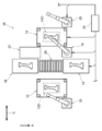
- FIG. 10 is a diagram showing a hot press device 96 according to the present embodiment.
- a heating furnace 98 is provided on the upstream side in the conveying direction of the material Z to be processed, and a press machine 100 is provided on the downstream side of the heating furnace 98.
- a first manipulator 102 which is an example of a conveying device that connects the heating furnace 98 and the press machine 100, is provided on the side of the heating furnace 98.
- the heating furnace 98 and the first manipulator 102 are within the conveyance range of the material Z.
- a press 100 is disposed.
- a roller hearth heating furnace 104 which is an example of a heating furnace, is provided on the downstream side of the press machine 100, and a pressing machine 106 is provided on the downstream side of the roller hearth heating furnace 104.
- the outlet 100B of the press machine 100 faces the charging port 104A of the roller hearth heating furnace 104, and the discharge port 104B of the roller hearth heating furnace 104 faces the charging port 106A of the press machine 106.
- the roller hearth heating furnace 104 is configured in substantially the same manner as in the fourth embodiment, and conveys the material Z charged from the charging port 104A to the discharge port 104B while heating.
- the in-furnace transport unit 104H that transports the material Z from the loading port 104A to the discharge port 104B is formed by the roller feed mechanism, and constitutes a part of the transport path.
- a second manipulator 108 which is an example of a conveying device that connects the press machine 100 and the roller hearth heating furnace 104, is provided at a side portion of the press machine 100 and between the press machine 100 and the roller hearth heating furnace 104. Yes.
- the outlet 100B of the press machine 100 and the inlet 104A of the roller hearth heating furnace 104 are provided in the conveyance range of the material Z by the second manipulator 108.
- a third manipulator 110 which is an example of a conveying device that connects the roller hearth heating furnace 104 and the press machine 106, is provided on the side of the roller hearth heating furnace 104 and between the roller hearth heating furnace 104 and the press machine 106. It has been.
- the discharge port 104 ⁇ / b> B of the roller hearth heating furnace 104 and the charging port 106 ⁇ / b> A of the press machine 106 are provided in the conveyance range of the material Z by the third manipulator 110.
- the structures of the press machines 100 and 106 and the manipulators 102, 108, and 110 are the same as those in the first embodiment.
- each manipulator 102, 108, 110, each press 100, 106, each heating furnace 98, 104, etc. shall operate
- the material Z (blank after heating) that has been heated for a predetermined time (for example, 4 minutes) after reaching a predetermined temperature (for example, 1000 ° C.) by the heating furnace 98 is taken out by the first manipulator 102 and the lower metal of the press 100 Set in mold 100D.
- the press machine 100 lowers the upper mold and press-molds the material Z (blank after heating) between the upper mold and the lower mold 100D. At this time, the heat of the material Z (blank after heating) is rapidly taken away by the upper mold and the lower mold 100D. In particular, the amount of heat removed is large while the mold reaches the bottom dead center and the material Z is held between the upper mold and the lower mold 100D. This is the first hot press.
- the time from when the material Z (blank after heating) is discharged from the heating furnace 98 to be held between the upper mold and the lower mold 100D is managed.
- the time is about 8 seconds, for example.
- the press machine 100 continuously presses the material Z (blank after heating) for a predetermined pressing time (for example, 10 seconds) and holds and cools it, and then raises the upper die.
- a predetermined pressing time for example, 10 seconds
- the second manipulator 108 lifts the material Z (intermediate product) pressed by the hook-type holding mechanism from the lower mold 100D and conveys it to the charging port 104A of the roller hearth heating furnace 104.
- This material Z (intermediate product) is heated while moving in the roller hearth heating furnace 104 for 2 minutes by roller driving, and reaches a predetermined temperature (900 ° C. as an example), and then is discharged from the discharge port 104B.
- a predetermined temperature 900 ° C. as an example
- the third manipulator 110 lifts up the material Z (intermediate product after heating) discharged from the discharge port 104B of the roller hearth heating furnace 104 by a hook-type holding mechanism, and is below the inlet 106A of the press machine 106. Set in the mold 106D.
- the press machine 106 descends the upper mold and press-molds the material Z (intermediate product after heating) between the upper mold and the lower mold 106D. At this time, the heat of the material Z (intermediate product after heating) is rapidly taken away by the upper mold and the lower mold 106D. In particular, the amount of heat removed while the mold reaches the bottom dead center and the material Z is held between the upper mold and the lower mold 106D is large. This is the second hot press molding.
- the time from when the material Z (intermediate product after heating) is discharged from the roller hearth heating furnace 104 to be held between the upper mold and the lower mold 106D is managed.
- the time is about 8 seconds, for example.
- the pressing machine 106 continuously presses and holds the material Z (intermediate product after heating) for a predetermined pressing time (for example, 15 seconds), then raises the upper die and opens the pressing machine 106.
- the pressed material Z (molded product) is lifted up from the lower mold 106D by a lift-up mechanism (not shown) of the press machine 106 and released.
- the third manipulator 110 lifts up the material Z (molded product) from the lower mold 106D and delivers it to the next process.
- roller hearth heating furnace 104 since the roller hearth heating furnace 104 is used as the heating furnace 98, the roller hearth heating furnace 104 can constitute a part of the transport device.
- the outlet 100B of the press machine 100 is arranged to face the charging port 104A of the roller hearth heating furnace 104, and the discharge port 104B of the roller hearth heating furnace 104 is arranged to face the charging port 106A of the press machine 106. For this reason, the temperature fall of the material Z at the time of conveyance can be suppressed.
- the hot press apparatus is A first press machine; A second press, A transport device connecting the first press machine and the second press machine; A heating furnace provided in a transfer range by the transfer device; It has.
- the hot press apparatus according to the second aspect is the first aspect, The transport device has a transport function from the first press machine or the second press machine to the heating furnace.
- the hot press apparatus according to the third aspect is the first or second aspect, A conveyance mechanism is provided that moves the material between a first arrangement position located in the heating furnace and a second arrangement position located in the conveyance range.
- the hot press apparatus according to the fourth aspect is the third aspect, The transport mechanism can transport in a reciprocating direction between the first placement position and the second placement position.
- the hot press device is the third or fourth aspect,
- the second arrangement position is set in front of at least one loading port of the first press machine and the second press machine.
- the hot press device according to the sixth aspect is any one of the third to fifth aspects,
- a hot press apparatus according to a seventh aspect is any one of the first to sixth aspects,
- the said conveying apparatus has an in-furnace conveyance part which conveys material from the charging inlet of the said heating furnace to a discharge port.
- the hot press apparatus is the seventh aspect,
- the outlet of the first press machine is opposed to the inlet of the heating furnace, and the outlet of the heating furnace is opposed to the inlet of the second press machine.
- a hot press apparatus is any one of the first to seventh aspects.
- Another heating furnace is further provided in the conveyance range of the said conveying apparatus.
Abstract
Description
この要求に対して、本発明者達は、加熱及び冷却サイクルを複数回繰り返すことで高強度特性を得られることを見出した。 A hot press member having high strength characteristics is used as a collision-resistant component for automobiles. This hot-pressed part is required to improve ductility and toughness in order to further increase the strength.
In response to this requirement, the present inventors have found that high strength characteristics can be obtained by repeating heating and cooling cycles a plurality of times.
以下、本開示の第1実施形態を図面を参照しつつ説明する。図中奥側を矢印A、上方を矢印B、横方向を矢印Cで示す。 (First embodiment)
Hereinafter, a first embodiment of the present disclosure will be described with reference to the drawings. In the figure, the back side is indicated by arrow A, the upper side is indicated by arrow B, and the lateral direction is indicated by arrow C.
第2マニピュレータ26は、プレス機12でプレスされた材料Zを他方の出入口12FOから排出して直線搬送機(図示省略)に積載し、直線搬送機により材料Zを高速で次工程へ搬送する。 A
The
第3マニピュレータ28は、プレス機14でプレスされた材料Zを他の出入口14FOから排出して直線搬送機(図示省略)に積載し、直線搬送機により材料Zを高速で次工程へ搬送できる。 A
The
また、搬送テーブル20の駆動部20Dがローラー20Cを回転するとともに加熱炉18の駆動部18Gがローラー18Fを回転する。これにより、搬送テーブル20の駆動部20D及び加熱炉18のローラー18Fは、ローラー駆動によって材料Z(ブランク)を加熱炉18内に収容する。 Then, the
Further, the
以下、本開示の第2実施形態を図面に従って説明する。
図4は、第2実施形態を示す図であり、第1実施形態と同一または同等部分については、同符号を付して説明を割愛するとともに、異なる部分についてのみ説明する。 (Second Embodiment)
Hereinafter, a second embodiment of the present disclosure will be described with reference to the drawings.
FIG. 4 is a diagram illustrating the second embodiment. The same or equivalent parts as those in the first embodiment are denoted by the same reference numerals, and the description thereof is omitted.
以下、本開示の第3実施形態を図面に従って説明する。
図5は、本実施形態の熱間プレス装置36を示す図であり、第1実施形態と同一または同等部分については、同符号を付して説明を割愛するとともに、異なる部分についてのみ説明する。 (Third embodiment)
Hereinafter, a third embodiment of the present disclosure will be described with reference to the drawings.
FIG. 5 is a view showing the
以下、本開示の第4実施形態を図面に従って説明する。 (Fourth embodiment)
Hereinafter, a fourth embodiment of the present disclosure will be described with reference to the drawings.
以下、本開示の第5実施形態を図面に従って説明する。 (Fifth embodiment)
Hereinafter, a fifth embodiment of the present disclosure will be described with reference to the drawings.
以下、本開示の第6実施形態を図面に従って説明する。 (Sixth embodiment)
Hereinafter, a sixth embodiment of the present disclosure will be described with reference to the drawings.
10 熱間プレス装置
12 プレス機
14 プレス機
16 第1マニピュレータ
18 加熱炉
18B 排出状態
18C 格納状態
20 搬送テーブル
24 コントローラ
30 熱間プレス装置
32 搬送機構
36 熱間プレス装置
38 第2加熱炉
40 熱間プレス装置
44 連続ローラーハース加熱炉
46 第1マニピュレータ
50 多段加熱炉
52 プレス機
54 プレス機
56 第2マニピュレータ
60 コントローラ
64 熱間プレス装置
68 連続ローラーハース加熱炉
70 プレス機
72 第2マニピュレータ
74 ローラーハース加熱炉
76 第3マニピュレータ
78 搬送テーブル
82 多段加熱炉
84 プレス機
86 プレス機
88 第4マニピュレータ
92 コントローラ
96 熱間プレス装置
98 加熱炉
100 プレス機
100B 取出口
102 第1マニピュレータ
104 ローラーハース加熱炉
104A 装入口
104B 排出口
106 プレス機
106A 装入口
108 第2マニピュレータ
110 第3マニピュレータ
112 コントローラ
≪付記≫
本明細書からは、以下の態様が概念化される。
すなわち、第1態様に係る熱間プレス装置は、
第1プレス機と、
第2プレス機と、
前記第1プレス機及び前記第2プレス機を繋ぐ搬送装置と、
該搬送装置による搬送範囲に設けられた加熱炉と、
を備えている。
第2態様に係る熱間プレス装置は、第1態様において、
前記搬送装置は、前記第1プレス機又は前記第2プレス機から前記加熱炉への搬送機能を備える。
第3態様に係る熱間プレス装置は、第1又は2態様において、
材料を前記加熱炉内に位置する第1の配置位置と前記搬送範囲に位置する第2の配置位置との間で移動する搬送機構を備えている。
第4態様に係る熱間プレス装置は、第3態様において、
前記搬送機構は、前記第1の配置位置と前記第2の配置位置との間を往復方向に搬送可能である。
第5態様に係る熱間プレス装置は、第3又は4態様において、
前記第1プレス機及び前記第2プレス機の少なくとも一方の装入口の正面に前記第2の配置位置が設定されている。
第6態様に係る熱間プレス装置は、第3~5態様のいずれかにおいて、
前記搬送装置を制御して前記第1プレス機からプレスした材料を取り出して該材料を前記第2の配置位置に搬送させるコントローラを備えている。
第7態様に係る熱間プレス装置は、第1~6態様のいずれかにおいて、
前記搬送装置は、前記加熱炉の装入口から排出口へ材料を搬送する炉内搬送部を有する。
第8態様に係る熱間プレス装置は、第7態様において、
前記第1プレス機の取出口が前記加熱炉の装入口に対向し、前記加熱炉の排出口が前記第2プレス機の装入口に対向している。
第9態様に係る熱間プレス装置は、第1~7態様のいずれかにおいて、
前記搬送装置の搬送範囲に他の加熱炉をさらに備える。
2016年9月6日に出願した日本国特許出願2016-173990号の開示は、その全体が参照により本明細書に取り込まれる。
また、本明細書に記載されたすべての文献、特許出願及び技術規格は、個々の文献、特許出願及び技術規格が参照により取り込まれることが具体的かつ個々に記された場合と同程度に、本明細書中に参照により取り込まれる。 The description of the symbols is described below.
DESCRIPTION OF
From this specification, the following aspects are conceptualized.
That is, the hot press apparatus according to the first aspect is
A first press machine;
A second press,
A transport device connecting the first press machine and the second press machine;
A heating furnace provided in a transfer range by the transfer device;
It has.
The hot press apparatus according to the second aspect is the first aspect,
The transport device has a transport function from the first press machine or the second press machine to the heating furnace.
The hot press apparatus according to the third aspect is the first or second aspect,
A conveyance mechanism is provided that moves the material between a first arrangement position located in the heating furnace and a second arrangement position located in the conveyance range.
The hot press apparatus according to the fourth aspect is the third aspect,
The transport mechanism can transport in a reciprocating direction between the first placement position and the second placement position.
The hot press device according to the fifth aspect is the third or fourth aspect,
The second arrangement position is set in front of at least one loading port of the first press machine and the second press machine.
The hot press device according to the sixth aspect is any one of the third to fifth aspects,
A controller that controls the transport device to take out the pressed material from the first press and transport the material to the second arrangement position;
A hot press apparatus according to a seventh aspect is any one of the first to sixth aspects,
The said conveying apparatus has an in-furnace conveyance part which conveys material from the charging inlet of the said heating furnace to a discharge port.
The hot press apparatus according to the eighth aspect is the seventh aspect,
The outlet of the first press machine is opposed to the inlet of the heating furnace, and the outlet of the heating furnace is opposed to the inlet of the second press machine.
A hot press apparatus according to a ninth aspect is any one of the first to seventh aspects.
Another heating furnace is further provided in the conveyance range of the said conveying apparatus.
The disclosure of Japanese Patent Application No. 2016-173990 filed on September 6, 2016 is incorporated herein by reference in its entirety.
In addition, all documents, patent applications, and technical standards described in this specification are the same as when individual documents, patent applications, and technical standards are specifically and individually described to be incorporated by reference. Incorporated herein by reference.
Claims (9)
- 第1プレス機と、
第2プレス機と、
前記第1プレス機及び前記第2プレス機を繋ぐ搬送装置と、
該搬送装置による搬送範囲に設けられた加熱炉と、
を備えた熱間プレス装置。 A first press machine;
A second press,
A transport device connecting the first press machine and the second press machine;
A heating furnace provided in a transfer range by the transfer device;
Hot press device with - 前記搬送装置は、前記第1プレス機又は前記第2プレス機から前記加熱炉への搬送機能を備える請求項1に記載の熱間プレス装置。 2. The hot press device according to claim 1, wherein the transport device has a transport function from the first press machine or the second press machine to the heating furnace.
- 材料を前記加熱炉内に位置する第1の配置位置と前記搬送範囲に位置する第2の配置位置との間で移動する搬送機構を備えた請求項1又は請求項2に記載の熱間プレス装置。 The hot press according to claim 1 or 2, further comprising a transport mechanism that moves a material between a first placement position located in the heating furnace and a second placement position located in the transport range. apparatus.
- 前記搬送機構は、前記第1の配置位置と前記第2の配置位置との間を往復方向に搬送可能である請求項3に記載の熱間プレス装置。 The hot press device according to claim 3, wherein the transport mechanism is capable of transporting in a reciprocating direction between the first arrangement position and the second arrangement position.
- 前記第1プレス機及び前記第2プレス機の少なくとも一方の装入口の正面に前記第2の配置位置が設定されている請求項3又は請求項4に記載の熱間プレス装置。 The hot press apparatus according to claim 3 or 4, wherein the second arrangement position is set in front of at least one loading port of the first press machine and the second press machine.
- 前記搬送装置を制御して前記第1プレス機からプレスした材料を取り出して該材料を前記第2の配置位置に搬送させるコントローラを備えた請求項3~請求項5のいずれかに記載の熱間プレス装置。 The hot apparatus according to any one of claims 3 to 5, further comprising a controller that controls the conveying device to take out the pressed material from the first press and convey the material to the second arrangement position. Press device.
- 前記搬送装置は、前記加熱炉の装入口から排出口へ材料を搬送する炉内搬送部を有する請求項1~請求項6のいずれかに記載の熱間プレス装置。 The hot press device according to any one of claims 1 to 6, wherein the transport device includes an in-furnace transport unit that transports material from an inlet to a discharge port of the heating furnace.
- 前記第1プレス機の取出口が前記加熱炉の装入口に対向し、前記加熱炉の排出口が前記第2プレス機の装入口に対向している請求項7に記載の熱間プレス装置。 The hot press apparatus according to claim 7, wherein an outlet of the first press machine is opposed to an inlet of the heating furnace, and an outlet of the heating furnace is opposed to an inlet of the second press machine.
- 前記搬送装置の搬送範囲に他の加熱炉をさらに備える請求項1~請求項7のいずれかに記載の熱間プレス装置。 The hot press device according to any one of claims 1 to 7, further comprising another heating furnace in a transport range of the transport device.
Priority Applications (9)
| Application Number | Priority Date | Filing Date | Title |
|---|---|---|---|
| RU2019108260A RU2709320C1 (en) | 2016-09-06 | 2017-08-31 | Device for hot pressing |
| KR1020197008676A KR102021403B1 (en) | 2016-09-06 | 2017-08-31 | Hot press device |
| BR112019004197A BR112019004197A2 (en) | 2016-09-06 | 2017-08-31 | hot press device |
| US16/330,339 US10981207B2 (en) | 2016-09-06 | 2017-08-31 | Hot press device |
| CN201780054009.2A CN109661281B (en) | 2016-09-06 | 2017-08-31 | Hot press device |
| MX2019002500A MX2019002500A (en) | 2016-09-06 | 2017-08-31 | Hot press device. |
| CA3035505A CA3035505C (en) | 2016-09-06 | 2017-08-31 | Hot press device |
| ES17848653T ES2861445T3 (en) | 2016-09-06 | 2017-08-31 | Hot press device |
| EP17848653.6A EP3511086B1 (en) | 2016-09-06 | 2017-08-31 | Hot press device |
Applications Claiming Priority (2)
| Application Number | Priority Date | Filing Date | Title |
|---|---|---|---|
| JP2016-173990 | 2016-09-06 | ||
| JP2016173990A JP6548620B2 (en) | 2016-09-06 | 2016-09-06 | Hot press machine |
Publications (1)
| Publication Number | Publication Date |
|---|---|
| WO2018047713A1 true WO2018047713A1 (en) | 2018-03-15 |
Family
ID=61562279
Family Applications (1)
| Application Number | Title | Priority Date | Filing Date |
|---|---|---|---|
| PCT/JP2017/031446 WO2018047713A1 (en) | 2016-09-06 | 2017-08-31 | Hot press device |
Country Status (11)
| Country | Link |
|---|---|
| US (1) | US10981207B2 (en) |
| EP (1) | EP3511086B1 (en) |
| JP (1) | JP6548620B2 (en) |
| KR (1) | KR102021403B1 (en) |
| CN (1) | CN109661281B (en) |
| BR (1) | BR112019004197A2 (en) |
| CA (1) | CA3035505C (en) |
| ES (1) | ES2861445T3 (en) |
| MX (1) | MX2019002500A (en) |
| RU (1) | RU2709320C1 (en) |
| WO (1) | WO2018047713A1 (en) |
Families Citing this family (4)
| Publication number | Priority date | Publication date | Assignee | Title |
|---|---|---|---|---|
| KR102185912B1 (en) * | 2018-12-24 | 2020-12-03 | (주)광진기계 | Fabrication method of magnesium part for vehicle |
| WO2020246396A1 (en) * | 2019-06-04 | 2020-12-10 | 日本製鉄株式会社 | Workpiece transportation tool, hot press device, workpiece transportation method, and hot press method |
| KR102330304B1 (en) * | 2019-10-01 | 2021-11-24 | 주식회사 광진 | Method for continuously producing automobile component |
| JP7448396B2 (en) | 2020-03-27 | 2024-03-12 | 住友重機械工業株式会社 | molding system |
Citations (3)
| Publication number | Priority date | Publication date | Assignee | Title |
|---|---|---|---|---|
| DE102006015666A1 (en) * | 2006-04-04 | 2007-10-11 | Daimlerchrysler Ag | Production of a metallic molded component, especially a chassis part, comprises forming the molded component from a semi-finished material by hot deforming and shearing the semi-finished material or molded component |
| JP2013212520A (en) * | 2012-04-02 | 2013-10-17 | Mazda Motor Corp | Electrical heating method and hot press forming method |
| JP2013240817A (en) * | 2012-05-22 | 2013-12-05 | Mazda Motor Corp | Hot press forming method and hot press forming device |
Family Cites Families (20)
| Publication number | Priority date | Publication date | Assignee | Title |
|---|---|---|---|---|
| SU1009805A1 (en) * | 1980-05-30 | 1983-04-07 | Украинский Научно-Исследовательский Институт Механической Обработки Древесины | Installation for manufacturing moulded articles |
| RU2057606C1 (en) * | 1992-10-20 | 1996-04-10 | Челябинский государственный технический университет | Shape making method |
| JP2004160489A (en) * | 2002-11-13 | 2004-06-10 | Nissan Motor Co Ltd | Method of press forming of panel part |
| JP4673656B2 (en) * | 2005-04-11 | 2011-04-20 | 新日本製鐵株式会社 | Hot press forming equipment |
| JP2007136534A (en) | 2005-11-22 | 2007-06-07 | Nippon Steel Corp | Press forming apparatus and press forming method |
| JP2008296237A (en) * | 2007-05-30 | 2008-12-11 | Aisin Takaoka Ltd | Multi-stage type heating apparatus |
| JP5155646B2 (en) | 2007-12-13 | 2013-03-06 | アイシン高丘株式会社 | Hot press molding apparatus and hot press molding method |
| JP5201003B2 (en) | 2008-04-30 | 2013-06-05 | 新日鐵住金株式会社 | Heating apparatus and method for hot press forming steel sheet |
| US20110283851A1 (en) * | 2010-05-21 | 2011-11-24 | Thyssenkrupp Sofedit S.A.S. | Method and hot forming system for producing press-hardened formed components of sheet steel |
| DE102010049205B4 (en) * | 2010-10-13 | 2012-04-26 | Elisabeth Braun | Hot forming line and method for hot forming sheet metal |
| JP5418728B2 (en) * | 2011-05-23 | 2014-02-19 | 新日鐵住金株式会社 | Hot press molding method and hot press mold |
| DE102012112334A1 (en) * | 2012-12-14 | 2014-06-18 | Manuela Braun | Warmumformvorrichtung |
| JP6115313B2 (en) * | 2013-05-24 | 2017-04-19 | 新日鐵住金株式会社 | Production line and production method for differential thickness steel plate products |
| US10195656B2 (en) * | 2013-09-12 | 2019-02-05 | Nippon Steel & Sumitomo Metal Corporation | Cooling method for hot press forming and hot press forming apparatus |
| DE102014101159B4 (en) * | 2014-01-30 | 2016-12-01 | Thyssenkrupp Steel Europe Ag | Process for the surface treatment of workpieces |
| DE102014109883B4 (en) * | 2014-07-15 | 2023-05-04 | Manuela Braun | Forming device for forming and subsequent press-hardening of a sheet metal blank or a preformed semi-finished product made of steel and steel workpiece produced therewith |
| KR20160035628A (en) * | 2014-09-23 | 2016-04-01 | 주식회사 웰탑테크노스 | A System for heating ultra high tensile steel plate |
| CN204724663U (en) * | 2015-07-01 | 2015-10-28 | 上海凌云汽车模具有限公司 | Produce the equipment of intensity adjustable thermoforming part |
| CN105195585B (en) * | 2015-09-07 | 2017-06-09 | 苏州普热斯勒先进成型技术有限公司 | Heat stamping and shaping production line |
| JP6388084B2 (en) * | 2016-05-18 | 2018-09-12 | 新日鐵住金株式会社 | Production method and production line for press-formed products |
-
2016
- 2016-09-06 JP JP2016173990A patent/JP6548620B2/en active Active
-
2017
- 2017-08-31 CA CA3035505A patent/CA3035505C/en not_active Expired - Fee Related
- 2017-08-31 RU RU2019108260A patent/RU2709320C1/en active
- 2017-08-31 WO PCT/JP2017/031446 patent/WO2018047713A1/en active Search and Examination
- 2017-08-31 ES ES17848653T patent/ES2861445T3/en active Active
- 2017-08-31 KR KR1020197008676A patent/KR102021403B1/en active IP Right Grant
- 2017-08-31 US US16/330,339 patent/US10981207B2/en active Active
- 2017-08-31 CN CN201780054009.2A patent/CN109661281B/en active Active
- 2017-08-31 BR BR112019004197A patent/BR112019004197A2/en not_active Application Discontinuation
- 2017-08-31 EP EP17848653.6A patent/EP3511086B1/en active Active
- 2017-08-31 MX MX2019002500A patent/MX2019002500A/en unknown
Patent Citations (3)
| Publication number | Priority date | Publication date | Assignee | Title |
|---|---|---|---|---|
| DE102006015666A1 (en) * | 2006-04-04 | 2007-10-11 | Daimlerchrysler Ag | Production of a metallic molded component, especially a chassis part, comprises forming the molded component from a semi-finished material by hot deforming and shearing the semi-finished material or molded component |
| JP2013212520A (en) * | 2012-04-02 | 2013-10-17 | Mazda Motor Corp | Electrical heating method and hot press forming method |
| JP2013240817A (en) * | 2012-05-22 | 2013-12-05 | Mazda Motor Corp | Hot press forming method and hot press forming device |
Also Published As
| Publication number | Publication date |
|---|---|
| US20190201961A1 (en) | 2019-07-04 |
| MX2019002500A (en) | 2019-07-18 |
| KR20190039322A (en) | 2019-04-10 |
| EP3511086A1 (en) | 2019-07-17 |
| CA3035505A1 (en) | 2018-03-15 |
| CN109661281B (en) | 2020-11-24 |
| CA3035505C (en) | 2020-02-11 |
| KR102021403B1 (en) | 2019-09-17 |
| CN109661281A (en) | 2019-04-19 |
| BR112019004197A2 (en) | 2019-05-28 |
| JP2018039023A (en) | 2018-03-15 |
| EP3511086A4 (en) | 2019-12-11 |
| JP6548620B2 (en) | 2019-07-24 |
| EP3511086B1 (en) | 2021-01-27 |
| RU2709320C1 (en) | 2019-12-17 |
| US10981207B2 (en) | 2021-04-20 |
| ES2861445T3 (en) | 2021-10-06 |
Similar Documents
| Publication | Publication Date | Title |
|---|---|---|
| WO2018047713A1 (en) | Hot press device | |
| US8460484B2 (en) | Method of making a shaped object with regions of different ductility | |
| JP6313770B2 (en) | Operating device | |
| CN101896292B (en) | Hot press forming device and hot press forming method | |
| JP4878564B2 (en) | Continuous carburizing furnace | |
| CN101322002B (en) | Method and apparatus for heating steel components in a straight-through furnace | |
| CN101896295A (en) | Conveyance equipment and hot press forming device having it | |
| CN106916930A (en) | Thermoforming line and its operation method for manufacturing the steel sheet product of thermoforming and pressure quench | |
| JP2018169137A (en) | Heat treatment furnace | |
| CN206838950U (en) | A kind of heat stamping and shaping production line with pre-cooler | |
| CN111826502B (en) | Quenching device and quenching method | |
| JP2018511485A (en) | Method, furnace apparatus and equipment for hot press forming a workpiece | |
| KR102353899B1 (en) | Multi cell Continuous Heat Treatment Furnace | |
| JP6721466B2 (en) | Heat treatment equipment | |
| JP2011523680A (en) | Furnace equipment for press hardening process | |
| JP2001232438A (en) | Method and apparatus for forging | |
| KR101003205B1 (en) | Heating oven for press hardening process | |
| EP1569874B1 (en) | Machine and process for shaping, annealing and quenching glass sheets, or similar materials | |
| US20170274438A1 (en) | Hot stamp cell | |
| RU2811801C2 (en) | Furnace with movable beam loading and unloading system | |
| JP6332807B2 (en) | Sinter hardening method | |
| JP2023123186A (en) | Method for manufacturing press molding | |
| KR20230138624A (en) | Heating Chamber Moving Type Continuous Heat Treatment Furnace | |
| CN115989134A (en) | Method for manufacturing press-formed article, tray used for the method, and hot-press line | |
| JP2014091129A (en) | Hot press molding facility, and hot press molding method |
Legal Events
| Date | Code | Title | Description |
|---|---|---|---|
| DPE2 | Request for preliminary examination filed before expiration of 19th month from priority date (pct application filed from 20040101) | ||
| 121 | Ep: the epo has been informed by wipo that ep was designated in this application |
Ref document number: 17848653 Country of ref document: EP Kind code of ref document: A1 |
|
| ENP | Entry into the national phase |
Ref document number: 3035505 Country of ref document: CA |
|
| NENP | Non-entry into the national phase |
Ref country code: DE |
|
| REG | Reference to national code |
Ref country code: BR Ref legal event code: B01A Ref document number: 112019004197 Country of ref document: BR |
|
| ENP | Entry into the national phase |
Ref document number: 20197008676 Country of ref document: KR Kind code of ref document: A |
|
| ENP | Entry into the national phase |
Ref document number: 2017848653 Country of ref document: EP Effective date: 20190408 |
|
| ENP | Entry into the national phase |
Ref document number: 112019004197 Country of ref document: BR Kind code of ref document: A2 Effective date: 20190228 |