WO2018047475A1 - 端末機器、サーバー、および情報処理システム - Google Patents
端末機器、サーバー、および情報処理システム Download PDFInfo
- Publication number
- WO2018047475A1 WO2018047475A1 PCT/JP2017/026175 JP2017026175W WO2018047475A1 WO 2018047475 A1 WO2018047475 A1 WO 2018047475A1 JP 2017026175 W JP2017026175 W JP 2017026175W WO 2018047475 A1 WO2018047475 A1 WO 2018047475A1
- Authority
- WO
- WIPO (PCT)
- Prior art keywords
- waveform data
- terminal device
- server
- vibration waveform
- processing unit
- Prior art date
- Legal status (The legal status is an assumption and is not a legal conclusion. Google has not performed a legal analysis and makes no representation as to the accuracy of the status listed.)
- Ceased
Links
Images






Classifications
-
- H—ELECTRICITY
- H04—ELECTRIC COMMUNICATION TECHNIQUE
- H04M—TELEPHONIC COMMUNICATION
- H04M1/00—Substation equipment, e.g. for use by subscribers
- H04M1/72—Mobile telephones; Cordless telephones, i.e. devices for establishing wireless links to base stations without route selection
- H04M1/724—User interfaces specially adapted for cordless or mobile telephones
-
- G—PHYSICS
- G08—SIGNALLING
- G08B—SIGNALLING SYSTEMS, e.g. PERSONAL CALLING SYSTEMS; ORDER TELEGRAPHS; ALARM SYSTEMS
- G08B6/00—Tactile signalling systems, e.g. tactile personal calling systems
-
- G—PHYSICS
- G06—COMPUTING OR CALCULATING; COUNTING
- G06F—ELECTRIC DIGITAL DATA PROCESSING
- G06F3/00—Input arrangements for transferring data to be processed into a form capable of being handled by the computer; Output arrangements for transferring data from processing unit to output unit, e.g. interface arrangements
- G06F3/01—Input arrangements or combined input and output arrangements for interaction between user and computer
-
- G—PHYSICS
- G06—COMPUTING OR CALCULATING; COUNTING
- G06F—ELECTRIC DIGITAL DATA PROCESSING
- G06F3/00—Input arrangements for transferring data to be processed into a form capable of being handled by the computer; Output arrangements for transferring data from processing unit to output unit, e.g. interface arrangements
- G06F3/01—Input arrangements or combined input and output arrangements for interaction between user and computer
- G06F3/016—Input arrangements with force or tactile feedback as computer generated output to the user
-
- G—PHYSICS
- G06—COMPUTING OR CALCULATING; COUNTING
- G06F—ELECTRIC DIGITAL DATA PROCESSING
- G06F3/00—Input arrangements for transferring data to be processed into a form capable of being handled by the computer; Output arrangements for transferring data from processing unit to output unit, e.g. interface arrangements
- G06F3/01—Input arrangements or combined input and output arrangements for interaction between user and computer
- G06F3/03—Arrangements for converting the position or the displacement of a member into a coded form
- G06F3/033—Pointing devices displaced or positioned by the user, e.g. mice, trackballs, pens or joysticks; Accessories therefor
- G06F3/038—Control and interface arrangements therefor, e.g. drivers or device-embedded control circuitry
-
- H—ELECTRICITY
- H04—ELECTRIC COMMUNICATION TECHNIQUE
- H04M—TELEPHONIC COMMUNICATION
- H04M3/00—Automatic or semi-automatic exchanges
- H04M3/42—Systems providing special services or facilities to subscribers
-
- G—PHYSICS
- G06—COMPUTING OR CALCULATING; COUNTING
- G06F—ELECTRIC DIGITAL DATA PROCESSING
- G06F2203/00—Indexing scheme relating to G06F3/00 - G06F3/048
- G06F2203/038—Indexing scheme relating to G06F3/038
- G06F2203/0383—Remote input, i.e. interface arrangements in which the signals generated by a pointing device are transmitted to a PC at a remote location, e.g. to a PC in a LAN
-
- G—PHYSICS
- G06—COMPUTING OR CALCULATING; COUNTING
- G06F—ELECTRIC DIGITAL DATA PROCESSING
- G06F2203/00—Indexing scheme relating to G06F3/00 - G06F3/048
- G06F2203/038—Indexing scheme relating to G06F3/038
- G06F2203/0384—Wireless input, i.e. hardware and software details of wireless interface arrangements for pointing devices
Definitions
- This technology relates to information processing technology using a tactile presentation device.
- the information processing system described in Patent Document 1 provides tactile information corresponding to an image in addition to visual information that a user views an image.
- the information processing apparatus in this information processing system sends haptic information for presenting haptic information associated with image information including a moving image or a still image to the receiving side apparatus.
- the tactile information is vibration waveform data.
- the receiving-side apparatus receives the tactile information and presents the tactile sensation to the user using a tactile sensation generating means such as a piezoelectric element together with the presentation of the image.
- Such an information processing system is applied to, for example, a tactile videophone system, a touch tactile telephone system, a tactile net shopping system, and a game distribution system with a tactile function (for example, paragraphs [0026] and [ [0027], [0031], etc.).
- An object of the present disclosure is to provide an information processing system that uses a tactile sense presentation technique to improve the interest of a user, and a terminal device and a server included in the information processing system.
- a terminal device includes a processing unit, a tactile information output unit, and a detection unit.
- the processing unit is configured to generate cutout waveform data by cutting out the vibration waveform data at a timing based on one or a plurality of periods of the vibration waveform data, and generate waveform data based on the cutout waveform data.
- the haptic information output unit is configured to generate and output haptic information corresponding to the waveform data generated by the processing unit.
- the detection unit is configured to detect an input signal due to a user action and to output the detected input signal as the vibration waveform data to the processing unit.
- This terminal device generates waveform data based on the cut-out waveform data cut out from the vibration waveform data at a timing based on one or a plurality of cycles. Thereby, the terminal device can generate tactile information corresponding to or based on the vibration waveform data by the tactile information output unit, and can reproduce the tactile sense at any time. Further, the terminal device can process the vibration waveform data corresponding to the user action input to the terminal device by the user. Therefore, the user's interest can be improved.
- the processing unit may be configured to generate superimposed waveform data by superimposing a plurality of cutout waveform data of vibration waveform data corresponding to the input signal detected by the detection unit.
- the haptic information output unit may be configured to generate and output haptic information corresponding to the superimposed waveform data.
- the terminal device may further include a communication unit configured to transmit and receive the vibration waveform data or the cut-out waveform data. Thereby, waveform data can be transmitted and received between the terminal device and the external device.
- the processing unit superimposes the cut-out waveform data of the first vibration waveform data corresponding to the input signal detected by the detection unit and the cut-out waveform data of the second vibration waveform data acquired through the communication unit. Accordingly, the superimposed waveform data may be generated.
- the haptic information output unit may be configured to generate and output haptic information corresponding to the superimposed waveform data.
- the user can receive a tactile sensation according to the superimposed waveform data in which the first vibration waveform data based on the user action and the other second vibration waveform data are superimposed. Therefore, the user can obtain, for example, a sense of unity with the sense of touch based on the second vibration waveform data, or a sense of unity and sense of unity with other users who have generated the second vibration waveform data.
- the extracted waveform data of the second vibration waveform data acquired via the communication unit includes the following two meanings.
- the communication unit may acquire the cut-out waveform data generated based on the second vibration waveform data, or the communication unit acquires the second vibration waveform data, and the processing unit uses the second vibration data. Cutout waveform data may be cut out. The same applies hereinafter.
- the processing unit superimposes the cut-out waveform data of the second vibration waveform data transmitted from another second terminal device acquired through the communication unit and the cut-out waveform data of the vibration waveform data. It may be configured to generate superimposed waveform data.
- the user can receive a tactile sensation according to the superimposed waveform data in which the first vibration waveform data based on the user action and the second vibration waveform data from the second terminal device are superimposed. . Therefore, the user can obtain, for example, a sense of unity with the sense of touch based on the second vibration waveform data, or a sense of unity and sense of unity with other users who have generated the second vibration waveform data.
- the detection unit may have a sensing function for starting generation of tactile information by the tactile information output unit.
- the processing unit may be configured to execute the clipping process based on a detection value obtained by the sensing function.
- the haptic information output unit may be configured to generate and output the haptic information based on the waveform data.
- the terminal device when the terminal device is in a predetermined state, the user can receive a tactile sensation based on the superimposed waveform data.
- the processing unit may include an application program for starting generation of haptic information by the haptic information output unit, and may be configured to execute the clipping process when the application program is activated.
- the haptic information output unit may be configured to generate and output the haptic information based on the waveform data.
- the server which concerns on one form comprises a communication part and a process part.
- the processing unit is configured to generate cutout waveform data by cutting out the vibration waveform data at a timing based on one or a plurality of periods of the vibration waveform data received by the communication unit.
- the processing unit transmits the vibration waveform data or the cut-out waveform data to the first terminal device via the communication unit in response to a transmission request from the first terminal device received by the communication unit. Configured to do.
- the processing unit When the first terminal device has a function of detecting an input signal due to a user action and transmitting the detected input signal as first vibration waveform data to the server, the processing unit is configured as follows. It may be. That is, the processing unit superimposes the cut-out waveform data of the second vibration waveform data transmitted from the second terminal device different from the first terminal device and the cut-out waveform data of the first vibration waveform data. By doing so, superimposed waveform data is generated, and the superimposed waveform data is transmitted to the first terminal device.
- the processing unit may be configured to further transmit the superimposed waveform data to the second terminal device in response to a transmission request from the second terminal device received by the communication unit.
- An information processing system includes the server and the terminal device.
- the interest of the user can be improved by using the tactile presentation technology.
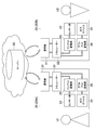
- FIG. 1 is a system configuration diagram illustrating the concept of the present technology.
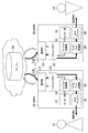
- FIG. 2 is a block diagram illustrating a configuration of an information processing system according to an embodiment of the present technology.
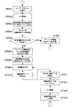
- FIG. 3 is a diagram for explaining an operation example 1-1 of the information processing system.
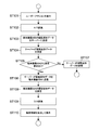
- FIG. 4 is a flowchart illustrating an operation example 1-1 in which the cutout process is not performed.
- FIG. 5 is a flowchart illustrating an operation example 1-2 in which the cutout process is not performed.
- FIG. 6 is a flowchart showing an operation example 2-1 for performing the clipping process and the superimposing process.
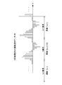
- FIG. 7 shows an example of vibration waveform data subjected to A / D conversion in the operation example 2-1.
- FIG. 8 is a diagram for explaining an operation at the time of uploading data to the server in the operation example 2-2 in which the clipping process and the superimposing process are performed.
- FIG. 9 is a diagram for explaining an operation at the time of downloading data from the server in the operation example 2-2.
- FIG. 10 is a flowchart showing the operation example 2-2.
- FIG. 11 is a flowchart illustrating an operation example 2-4 for performing cutout processing and superimposition processing.
- Fig. 1 shows the concept of this technology.
- a shared world as a virtual world for a plurality of users for example, U1 and U2
- the shared world is realized by a cloud including the server 50, for example.
- Each terminal device 20 copies the shared world and presents the shared world to the users U1 and U2 as tactile information (force sense also has the same meaning as tactile sense).
- the server 50 is not an essential element, and the shared world may be realized by connecting the terminal devices 20 in a peer-to-peer manner. Further, the number of users (terminal devices 20) is not necessarily limited to a plurality, and an information processing system in which one terminal device 20 used by one user is connected to the server 50 is also included in the scope of the present technology. Alternatively, processing by the one terminal device 20 that is not connected to the server 50 is also included in the scope of the present technology.
- FIG. 2 is a block diagram showing a configuration of an information processing system according to an embodiment of the present technology.
- the information processing system includes a server 50 in the cloud and a plurality of terminal devices 20 connected to the server 50. Any known tactile sense presentation device can be used as the terminal device 20.
- terminal device 20A used by the user U1 and the terminal device 20B used by the user U2 is the same, only one terminal device 20 will be described. Below, when it is necessary to distinguish and explain these terminal devices 20A and 20B, the terminal device 20 used by the user U1 is referred to as a terminal device 20A, and the terminal device 20 used by the user U2 is referred to as a terminal device 20B.
- the terminal device 20 includes a communication unit 21, a simulator 22, a sensor unit 23, an output device 24, an input converter 25, and an output converter 26.
- the communication unit 21 is typically a communication interface that can be connected by IP (Internet Protocol).
- IP Internet Protocol
- the sensor unit 23 detects an input signal to the terminal device 20 by a “user action” by the user.
- the user action is an action of input to the terminal device 20A by the user U1 to share the movement with the user U2 (the terminal device 20B) when the user U1 grasps the terminal device 20A and moves it intentionally. It is.
- the user action by the user U2 on the terminal device 20B has the same meaning.
- the sensor unit 23 is composed of various one or more types of sensors.
- the sensor include a motion sensor (at least one of a gyro sensor, an acceleration sensor, and a geomagnetic sensor), a pressure sensor, a contact sensor, and the like.
- the input converter 25 is an A / D converter that converts an analog signal detected by the sensor unit 23 into a digital signal.
- the sensor unit 23, or the sensor unit 23 and the input converter 25 function as a “detection unit”.
- the output device 24 is a device configured to generate a partial acceleration in at least one of the 1 to 3 axes orthogonal to each other. Thereby, the output device 24 presents tactile information to the user.
- the output device 24 typically includes an actuator and a weight driven by the actuator.
- an actuator of a haptic presentation device disclosed in International Publication No. 2015/151380 filed by the present applicant can be used.
- the output device 24 is not limited to a piezoelectric actuator, and includes a linear resonance actuator, a magnetostrictive actuator, an electrostatic actuator, and the like.
- the sensor unit 23 has a sensing function for starting the generation of tactile information in the previous stage of the input signal to the terminal device 20 by a user action, or for starting the clipping process from the vibration waveform data as will be described later.
- the input operation to the terminal device 20 by the user which is the object of this sensing, is hereinafter referred to as “user trigger action” and is conceptually distinguished from “user action”.
- the user-triggered action includes, for example, actions such as the user holding the terminal device 20, holding it in a predetermined posture, holding it with a predetermined force, and pressing a predetermined area of the terminal device 20.
- the processing unit to be described later of the terminal device 20 is configured such that the sensor unit 23 executes a clipping process to be described later based on the vibration waveform data based on the detection value (for example, when the detection value exceeds a threshold). .
- the user-triggered action may be to start an application program for starting the generation or cut-out processing of tactile information by the output device 24 without depending on the sensing of the sensor unit 23.
- the output converter 26 is a D / A converter that converts a digital signal from the simulator 22 into an analog signal.
- the sensor unit 23, or the sensor unit 23 and the output converter 26 function as a “tactile information output unit”.
- the simulator 22 generates cutout waveform data by cutting out the vibration waveform data at a timing based on one or a plurality of cycles of the vibration waveform data.
- the simulator 22 may store the generated cutout waveform data in a storage unit (not shown).
- the simulator 22 also has a function of generating waveform data (for example, superimposed waveform data) based on the cut-out waveform data as will be described later.
- the simulator mainly functions as a “processing unit”.
- the vibration waveform data is data indicating the movement of the terminal device 20 due to the user action detected by the sensor unit 23.
- the terminal device 20 may acquire vibration waveform data, cut-out waveform data, or superimposed waveform data from the server 50 in some cases. That is, the terminal device 20A can send vibration waveform data (first vibration waveform data) based on the user action input by the user U1 to the terminal device 20B via the server 50.
- the terminal device 20B can also send vibration waveform data (second vibration waveform data) based on the user action input by the user U2 to the terminal device 20A via the server 50.
- the terminal device 20 includes, as hardware, a CPU (Central Processing Unit), a RAM (Random Access Memory), and a ROM (Read Only Memory) (not shown).
- a CPU Central Processing Unit
- RAM Random Access Memory
- ROM Read Only Memory
- DSP Digital Signal Processor
- PLD Programmable Logic Device
- the storage unit described above includes a rewritable ROM, a hard disk drive, and other memories.
- the server 50 includes hardware such as a CPU (server-side processing unit), RAM, ROM, and a communication interface (server-side communication unit).
- the server 50 includes a storage unit that stores the vibration waveform data sent from the terminal device 20 and the generated cutout waveform data.
- Operation example 1-1 shows an example of simultaneous operation.
- a user holds the terminal device 20 at the same time, one user inputs a user action, and the other user receives information corresponding thereto. That is, in this operation example 1, an example in which users share tactile information in real time will be described.
- “simultaneously” means a case where one user inputs a user action while the other user inputs a user trigger action (for example, lifting the terminal device 20). The same applies hereinafter.
- FIG. 3 is a diagram for explaining the operation example 1-1
- FIG. 4 is a flowchart showing the operation.
- Examples of user actions include, for example, grasping the terminal device 20, shaking up and down, tapping, pushing, turning, rubbing, or a combination of at least two of these. For example, when the terminal device 20 is held and shaken up and down, the feeling of shaking hands is shared between the two users.
- User U2 inputs a user action to the terminal device 20B.
- the sensor unit 23 of the terminal device 20B detects it and performs A / D conversion (steps 101 and 102).
- the simulator 22 of the terminal device 20B acquires the vibration waveform data, and transmits the vibration waveform to the server 50 via the communication unit 21 (step 103).
- the server 50 receives this vibration waveform data (step 104).
- the server 50 detects whether or not a vibration waveform data transmission request is received from the terminal device 20A of the user U1 (step 105). That is, whether or not the user U1 is using the terminal device 20A is detected in real time when a user action is input to the terminal device 20B. Specifically, when the user U1 inputs a user trigger action to the terminal device 20A, the terminal device 20A transmits the transmission request to the server 50.
- the server 50 transmits the vibration waveform received from the terminal device 20B to the terminal device 20A in real time (step 106).
- the server 50 stores the vibration waveform data (step 107).
- the server 50 may store vibration waveform data having a predetermined time length after receiving the vibration waveform data, or may store vibration waveform data having a predetermined amount of data.
- the server 50 may generate cutout waveform data described later from the vibration waveform data and store it.
- the terminal device 20A receives the vibration waveform data sent from the server 50 (step 108), and the simulator 22 acquires the vibration waveform data.
- the terminal device 20A performs D / A conversion (step 109), and the output device 24 generates haptic information corresponding to the vibration waveform data, and drives the actuator according to the haptic information, whereby the user U1.
- the tactile sense is presented to (step 110).
- the user U2 terminal device 20A receives in real time the user action information input by the user U2 to the terminal device 20B, and the user U1 receives a tactile sensation.
- the user U1 can share information on user actions by the user U2 in real time by touch.
- Operation example 1-2 shows an example of non-simultaneous operation.
- the non-simultaneous operation is not real-time as in the first operation example, but the other user's terminal device 20 receives the information of the user action input to the terminal device 20 by one user at a time.
- FIG. 5 is a flowchart showing the operation.
- This operation example 1-2 is an operation after step 107 in the operation example 1-1.
- the description of the same parts as those in the first operation example will be omitted.
- the server 50 stores vibration waveform data at step 107.
- the server 50 detects whether or not a transmission request for the vibration waveform data from the terminal device 20B to the terminal device 20A has been received (step 201).
- the server 50 receives the transmission request, the subsequent processing is the same as the above-described steps 106 to 110 (steps 202 to 205).
- the user U1 can receive a tactile sensation when the terminal device 20A receives the vibration waveform data of the terminal device 20B stored in the server 50, even in real time.
- FIG. 6 is a flowchart showing the operation of the terminal device 20.
- FIG. 7 shows an example of the A / D converted vibration waveform data W t in step 302.
- the determination of the frequency is performed by, for example, Fourier transform. Thereby, cut-out waveform data is generated.
- the cut-out waveform data is represented as W (n) t .
- the first period of vibration waveform data is T (1) , ..., the n-1st period is T (n-1) , the nth period is T (n) , and the n + 1th period is T (n + 1) ,...
- Each cut-out waveform data cut out every cycle is: W (n-2) t , W (n-1) t , W (n) t , W (n + 1) t ,. ⁇ It is.
- the parentheses indicate the order (number of times) of the obtained cycles.
- the (n-1) th cut-out waveform data W (n-1) t is converted to T (n-1) -1 (the end of the previous cycle from the time when the data of the (n-1) th cycle is obtained. It is expressed as waveform data cut out at the timing of (1).
- the n-th cut-out waveform data W (n) t is represented as waveform data cut out at T (n) ⁇ 1.
- the (n + 1) th cut-out waveform data W (n + 1) t is represented as waveform data cut out at T (n + 1) ⁇ 1.
- the simulator 22 repeats steps 303 and 304 to generate cut waveform data for the number of repetitions cut out at the timing of each cycle as described above.
- the simulator 22 may store at least one cut-out waveform data cut out in the storage unit.
- the simulator 22 obtains the superimposed waveform data WB (n) t by sequentially superimposing each of the cut-out waveform data W (n) t repeatedly generated according to the following equation (1) (step 305).
- the superimposed waveform data is obtained by performing the moving average process for 10 times.
- WB (n) t WB (n-1) t + (W (n) t -W (n-10) t ) / 10 (1)
- Equation (2) indicates the period (loop period) TT (n) of the superimposed waveform data.
- TT (n) TT (n-1) + (T (n) -T (n-10) ) / 10 (2)
- Steps 307 and 308 are the same processes as steps 109 and 110.
- the user can continuously input the user action to his / her terminal device 20 to amplify it in real time and receive a tactile sensation according to the amplified vibration waveform data.
- the user's interest can be improved.
- the upper limit of the amplitude of the superimposed waveform data only needs to be set to a predetermined value. Further, in the above description, the number of samplings in the moving average process is 10, but it may be smaller or larger than this.
- FIG. 10 is a flowchart showing the operation of the information processing system at that time.
- steps 101 to 105 When one user, for example, the user U2 inputs a user action to the terminal device 20B, the same processing as steps 101 to 105 (see FIG. 4) is executed (steps 401 to 405).
- the server 50 receives a transmission request from the terminal device 20A (Yes in step 405). That is, the server 50 is in a state of receiving vibration waveform data from the terminal device 20A. In this case, the process proceeds to step 406. When there is no transmission request, it is a non-simultaneous operation, and the server 50 stores the vibration waveform data in the storage unit (step 407).
- the processing unit of the server 50 executes the same processing as Steps 303 to 306 shown in Operation Example 2-1 (Steps 406 and 408 to 410).
- the superimposed waveform data WB (n) t of the cut-out waveform data of the vibration waveform data of the terminal devices 20A and 20B is expressed by the following equation (3).
- the cut-out waveform data of the vibration waveform data by the terminal device 20A is assumed to be WX (n) t .
- the cut-out waveform data of the vibration waveform data by the terminal device 20B is defined as WY (n) t .
- the sampling number of the moving average process is 10.
- WB (n) t WB (n-1) t + (WX (n) t + WY (n) t -WX (n-10) t -WY (n-10) t ) / 20 ... (3 )
- the loop period TT (n) is expressed by the following equation (4).
- TT (n) TT (n-1) + (TX (n) + TY (n ) -TX (n-10) -TY (n-10) ) / 20 (4)
- the terminal device 20 extraction waveform data WZ (n) t of the vibration waveform data
- the superimposed waveform data WB (n) t and the loop period TT (n) of the three extraction waveform data are as follows: (5) and (6), respectively.
- WB (n) t WB (n-1) t + (WX (n) t + WY (n) t + WZ (n) t -WX (n-10) t -WY (n-10) t -WZ (n-10) t ) / 30 ... (5)
- TT (n) TT (n-1) + (TX (n) + TY (n) + TZ (n ) -TX (n-10) -TY (n-10) -TZ (n-10) ) / 30 ⁇ ⁇ ⁇ (6)
- the server 50 transmits the superimposed waveform data to both the terminal device 20A and the terminal device 20B (step 410).
- Each of the terminal devices 20A and 20B receives the superimposed waveform data, and presents haptics corresponding to the superimposed waveform data in real time to the users U1 and U2, respectively (steps 411 to 413).
- This operation example 2-2 allows the users U1 and U2 to share the tactile sense based on the superimposed waveform data in real time, thereby obtaining a sense of sharing and unity.
- Operation Example 2-3 an example of non-simultaneous operation when cutting out waveform data of vibration waveform data is superimposed will be described.
- This operation example 2-3 is an operation after step 407 in the above operation example 2-2.
- a flowchart is not shown.
- step 407 when the server 50 receives a transmission request from the terminal device 20A, it executes steps 406 to 409. That is, the server 50 generates superimposed waveform data of the stored cutout waveform data of the terminal device 20B and the cutout waveform data of the terminal device 20A based on the user action of the user U1 currently received.
- the server 50 transmits the superimposed waveform data to the terminal device 20A, and the terminal device 20A receives the superimposed waveform data and presents a tactile sense based on the superimposed waveform data to the user U1.
- FIG. 11 is a flowchart showing the operation.
- Steps 501 to 505 and 507 are the same processing as steps 401 to 405 and 407 in the operation example 2-2.
- step 505 when the server 50 receives a transmission request from the terminal device 20A, it is in a state of receiving vibration waveform data from the terminal device 20A. In this case, the server 50 transmits the vibration waveform data from the terminal device 20B to the terminal device 20A, and transmits the vibration waveform data from the terminal device 20A to the terminal device 20B (step 506).
- the terminal devices 20A and 20B receive the vibration waveform data.
- the simulator 22 of the terminal device 20A generates cut-out waveform data of the received vibration waveform data of the terminal device 20B and cut-out waveform data of vibration waveform data by the user U1 currently input to the terminal device 20A and superimposes them. (Steps 509 to 511).
- the simulator 22 of the terminal device 20B generates the cut-out waveform data of the received vibration waveform data of the terminal device 20A and the cut-out waveform data of the vibration waveform data by the user U2 currently input to the terminal device 20B. Are superimposed (steps 509 to 511).
- the terminal device 20A presents a haptic corresponding to the superimposed waveform data to the user U1 (steps 512 to 514), and the terminal device 20B similarly presents a haptic corresponding to the superimposed waveform data to the user U2 (steps 512 to 514). 514).
- the non-simultaneous operation example (operation example 2-5) after step 507 is the same as the operation example 2-3 except that the simulator 22 of each terminal device 20A executes the superimposition process. Is omitted.
- the information processing system that executes the operation example 2 can present a tactile sensation that, for example, two users hold the terminal device 20 and walk while holding hands.
- a tactile sensation that, for example, two users hold the terminal device 20 and walk while holding hands.
- their amplitudes are amplified, so that their superimposed waveform data is also amplified, so that the sense of touch is also amplified.
- the information processing system can be applied to sports watching and live watching.
- a plurality of users in the venue of the site can have the terminal device 20 and share a tactile sensation according to the waveform data at the time of support.
- the waveform data generated by the user's terminal device 20 at the site or the venue is the terminal device of the user in the region 20 is sent.
- users in remote areas can also share the realism of the site and the excitement of the users.
- the user can receive input of user actions and presentation of tactile sensation while watching the recorded video.
- the information processing system according to the present technology can also be applied to education and learning.
- the server 50 or the terminal device 20 stores a movement modeled by a teacher as vibration waveform data.
- the student can use the terminal device 20 to reproduce the movement and rhythm corresponding to the vibration waveform data as an example on the terminal device 20 and input a user action in accordance with the movement and rhythm. .
- this is also possible in real time or non-real time. 5).
- the terminal device 20 generates the superimposed waveform data as “waveform data” by superimposing the cutout waveform data.
- another waveform data may be generated based on the cut-out waveform data, instead of generating the superimposed waveform data.
- the terminal device 20 may generate another waveform data by changing the amplitude and / or frequency of the cut-out waveform data, in whole or in part. This is also applicable to the server 50.
- the processing unit of the server 50 or the simulator 22 generates the cut-out waveform data at the timing of each cycle, but may be configured to generate it at the timing of every plurality of cycles.
- the server 50 generates cutout waveform data and superimposed waveform data.
- the server 50 may generate cutout waveform data and transmit it to the terminal device 20, and the terminal device 20 may generate superimposed waveform data based on the received cutout waveform data.
- Such processing is also applicable to the operation example 2-4 (and 2-5) shown in FIG.
- the server 50 may store the vibration waveform data (second vibration waveform data) or the cut-out data thereof as sample data in advance.
- one or more terminal devices 20 can access it and the sample data can be reproduced by the terminal device 20.
- the one or more terminal devices 20 are configured to generate superimposed waveform data of the sample data and vibration waveform data (cut-out waveform data) based on the user action input to the one or more terminal devices 20. May be.
- the server 50 can provide the terminal device 20 with the sample data together with the video data when the liquid or marble moves in the cup.
- One or a plurality of users can input and amplify the vibration waveform data of their own user action in the movement by inputting the user action to the terminal device 20.
- the server 50 is not limited to providing such video data and vibration waveform data, and the terminal device 20 may hold the video data and sample data in advance.
- the information processing system includes the server 50, and the system is constructed by a wide area network.
- a plurality of terminal devices 20 may be connected by a peer-to-peer connection or a local area network connection without the server 50.
- the simulator 22 of the terminal device 20 is configured to generate the cut-out waveform data and the superimposed waveform data.
- a processing unit configured to generate cutout waveform data by cutting out the vibration waveform data at a timing based on one or a plurality of periods of the vibration waveform data, and to generate waveform data based on the cutout waveform data;
- a haptic information output unit configured to generate and output haptic information corresponding to the waveform data generated by the processing unit;
- a terminal device comprising: a detection unit configured to detect an input signal due to a user action and output the detected input signal as the vibration waveform data to the processing unit.
- the processing unit is configured to generate superimposed waveform data by superimposing a plurality of cutout waveform data of vibration waveform data corresponding to the input signal detected by the detection unit, The terminal device configured to generate and output tactile information corresponding to the superimposed waveform data.
- a terminal device further comprising a communication unit configured to transmit and receive the vibration waveform data or the cut-out waveform data.
- the processing unit superimposes the cut-out waveform data of the first vibration waveform data corresponding to the input signal detected by the detection unit and the cut-out waveform data of the second vibration waveform data acquired through the communication unit.
- the terminal device Configured to generate superimposed waveform data, The terminal device configured to generate and output tactile information corresponding to the superimposed waveform data.
- the processing unit superimposes the cut-out waveform data of the second vibration waveform data transmitted from another second terminal device acquired through the communication unit and the cut-out waveform data of the vibration waveform data.
- a terminal device configured to generate superimposed waveform data.
- the detection unit has a sensing function for starting generation of tactile information by the tactile information output unit,
- the processing unit is configured to execute the clipping process based on a detection value by the sensing function,
- the terminal device configured to generate and output the tactile information based on the waveform data.
- the processing unit has an application program for starting generation of haptic information by the haptic information output unit, and is configured to execute the cutting process when the application program is activated.
- the terminal device configured to generate and output the tactile information based on the waveform data.
- a communication department A processing unit configured to generate cutout waveform data by cutting out the vibration waveform data at a timing based on one or a plurality of periods of the vibration waveform data received by the communication unit;
- the processing unit transmits the vibration waveform data or the cut-out waveform data to the first terminal device via the communication unit in response to a transmission request from the first terminal device received by the communication unit. Configured to be a server.
- the server according to (8) above When the first terminal device has a function of detecting an input signal due to a user action and transmitting the detected input signal to the server as first vibration waveform data, The processing unit superimposes cut-out waveform data of second vibration waveform data transmitted from a second terminal device different from the first terminal device and cut-out waveform data of the first vibration waveform data. A server configured to generate superimposed waveform data by transmitting the superimposed waveform data to the first terminal device. (10) The server according to (9) above, The server configured to further transmit the superimposed waveform data to the second terminal device in response to a transmission request from the second terminal device received by the communication unit.
- the server side communication unit has a server side processing unit configured to transmit vibration waveform data
- the terminal device is A communication unit for receiving the vibration waveform data transmitted from the server;
- a processing unit configured to generate cutout waveform data by cutting out the vibration waveform data at a timing based on one or a plurality of periods of the received vibration waveform data, and to generate waveform data based on the cutout waveform data;
- a haptic information output unit configured to generate and output haptic information corresponding to the waveform data generated by the processing unit;
- a detection unit and an information processing system configured to detect an input signal due to a user action and output the detected input signal as the vibration waveform data to the processing unit.
- a server and terminal equipment The server The server-side communications department;
- the waveform data is cut out by cutting out the vibration waveform data at a timing based on one or more periods of the vibration waveform data received by the communication unit.
- the terminal device is A communication unit configured to receive the waveform data;
- An information processing system comprising: a tactile information output unit configured to generate and output tactile information corresponding to the waveform data received by the communication unit.
Landscapes
- Engineering & Computer Science (AREA)
- General Engineering & Computer Science (AREA)
- Theoretical Computer Science (AREA)
- Human Computer Interaction (AREA)
- Physics & Mathematics (AREA)
- General Physics & Mathematics (AREA)
- Signal Processing (AREA)
- Computer Networks & Wireless Communication (AREA)
- User Interface Of Digital Computer (AREA)
- Telephonic Communication Services (AREA)
Abstract
端末機器は、処理部と、触覚情報出力部と、検出部とを具備する。前記処理部は、振動波形データの1または複数の周期に基づくタイミングでこの振動波形データを切り出すことにより切り出し波形データを生成し、この切り出し波形データに基づく波形データを生成するように構成される。前記触覚情報出力部は、前記処理部により生成された前記波形データに応じた触覚情報を生成して出力するように構成される。前記検出部は、ユーザーアクションによる入力信号を検出し、検出した入力信号を前記振動波形データとして前記処理部へ出力するように構成される。
Description
本技術は、触覚提示デバイスを利用した情報処理の技術に関する。
特許文献1に記載の情報処理システムは、ユーザーが画像を視るという視覚の情報に加えて、画像に対応された触覚の情報を提供する。具体的には、この情報処理システムにおける情報処理装置は、動画または静止画を含む画像情報に対応付けられた触覚提示用の触覚情報を、受信側装置へ送る。触覚情報とは、振動の切り出し波形データである。受信側装置はその触覚情報を受信し、画像の提示とともに、例えば圧電素子等の触覚発生手段を用いて触覚をユーザーに提示する。このような情報処理システムは、例えば触覚テレビ電話システムや、感動触覚電話システム、触覚ネットショッピングシステム、触覚機能付きゲーム配信システムに応用される(例えば、特許文献2の明細書段落[0026]、[0027]、[0031]等を参照。)。
上記のように触覚提示の技術を利用して多様な装置やサービスが期待されており、ユーザーの興趣を向上させる新たなシステムが求められている。
本開示の目的は、触覚提示技術を利用してユーザーの興趣を向上させる情報処理システム、これに含まれる端末機器およびサーバーを提供することにある。
上記目的を達成するため、本技術に係る端末機器は、処理部と、触覚情報出力部と、検出部とを具備する。
前記処理部は、振動波形データの1または複数の周期に基づくタイミングでこの振動波形データを切り出すことにより切り出し波形データを生成し、この切り出し波形データに基づく波形データを生成するように構成される。
前記触覚情報出力部は、前記処理部により生成された前記波形データに応じた触覚情報を生成して出力するように構成される。
前記検出部は、ユーザーアクションによる入力信号を検出し、検出した入力信号を前記振動波形データとして前記処理部へ出力するように構成される。
前記処理部は、振動波形データの1または複数の周期に基づくタイミングでこの振動波形データを切り出すことにより切り出し波形データを生成し、この切り出し波形データに基づく波形データを生成するように構成される。
前記触覚情報出力部は、前記処理部により生成された前記波形データに応じた触覚情報を生成して出力するように構成される。
前記検出部は、ユーザーアクションによる入力信号を検出し、検出した入力信号を前記振動波形データとして前記処理部へ出力するように構成される。
この端末機器は、振動波形データから1または複数の周期に基づくタイミングで切り出された切り出し波形データに基づく波形データを生成する。これにより、端末機器は、振動波形データに応じた、またはこれに基づく触覚情報を触覚情報出力部により生成して、いつでもその触覚を再現することができる。また、端末機器は、ユーザーが自らこの端末機器に入力したユーザーアクションに応じた振動波形データを処理することができる。したがって、ユーザーの興趣の向上を図ることができる。
前記処理部は、前記検出部により検出された前記入力信号に応じた振動波形データの複数の切り出し波形データを重畳することにより重畳波形データを生成するように構成されていてもよい。
前記触覚情報出力部は、前記重畳波形データに応じた触覚情報を生成して出力するように構成されていてもよい。
前記触覚情報出力部は、前記重畳波形データに応じた触覚情報を生成して出力するように構成されていてもよい。
前記端末機器は、前記振動波形データまたは前記切り出し波形データを送受信するように構成された通信部をさらに具備してもよい。これにより、端末機器と外部機器との間で波形データを送受信することができる。
前記処理部は、前記検出部により検出された前記入力信号に応じた第1振動波形データの切り出し波形データと、前記通信部を介して取得した第2振動波形データの切り出し波形データとを重畳することにより重畳波形データを生成するように構成されていてもよい。
前記触覚情報出力部は、前記重畳波形データに応じた触覚情報を生成して出力するように構成されていてもよい。
前記触覚情報出力部は、前記重畳波形データに応じた触覚情報を生成して出力するように構成されていてもよい。
これにより、ユーザーは、自らのユーザーアクションに基づく第1振動波形データと、別の第2振動波形データとが重畳された重畳波形データに応じた触覚の提示を受けることができる。したがってユーザーは、例えば第2振動波形データによる触覚との一体感、あるいはその第2振動波形データを生成した他のユーザーとの共有感や一体感を得ることができる。
「通信部を介して取得した第2振動波形データの切り出し波形データ」とは、次の2つの意味を含む。通信部が、第2振動波形データに基づき生成された切り出し波形データを取得してもよいし、あるいは、通信部が、第2振動波形データを取得して、処理部がその第2振動データから切り出し波形データを切り出してもよい。以下、同様である。
前記処理部は、前記通信部を介して取得した、別の第2の端末機器から送信された第2振動波形データの切り出し波形データと、前記振動波形データの切り出し波形データとを重畳することにより重畳波形データを生成するように構成されていてもよい。
これにより、ユーザーは、自らのユーザーアクションに基づく第1振動波形データと、第2の端末機器からの第2振動波形データとが重畳された重畳波形データに応じた触覚の提示を受けることができる。したがってユーザーは、例えば第2振動波形データによる触覚との一体感、あるいはその第2振動波形データを生成した他のユーザーとの共有感や一体感を得ることができる。
前記検出部は、前記触覚情報出力部による触覚情報の生成を開始するためのセンシング機能を有していてもよい。
前記処理部は、前記センシング機能による検出値に基づき、前記切り出しの処理を実行するように構成されていてもよい。
前記触覚情報出力部は、前記波形データに基づく前記触覚情報を生成して出力するように構成されていてもよい。
前記処理部は、前記センシング機能による検出値に基づき、前記切り出しの処理を実行するように構成されていてもよい。
前記触覚情報出力部は、前記波形データに基づく前記触覚情報を生成して出力するように構成されていてもよい。
これにより、端末機器が所定の状態にある場合に、ユーザーは重畳波形データに基づく触覚の提示を受けることができる。
前記処理部は、前記触覚情報出力部による触覚情報の生成を開始するためのアプリケーションプログラムを有し、前記アプリケーションプログラムを起動した場合、前記切り出しの処理を実行するように構成されていてもよい。
前記触覚情報出力部は、前記波形データに基づく前記触覚情報を生成して出力するように構成されていてもよい。
前記触覚情報出力部は、前記波形データに基づく前記触覚情報を生成して出力するように構成されていてもよい。
これにより、ユーザーがアプリケーションプログラムを起動した場合に、重畳波形データに基づく触覚の提示を受けることができる。
一形態に係るサーバーは、通信部と、処理部とを具備する。
前記処理部は、前記通信部により受信された振動波形データの1または複数の周期に基づくタイミングでこの振動波形データを切り出すことにより切り出し波形データを生成するように構成される。
前記処理部は、前記通信部により受信された第1の端末機器からの送信要求に応じて、前記振動波形データまたは前記切り出し波形データを、前記通信部を介して前記第1の端末機器に送信するように構成される。
前記処理部は、前記通信部により受信された振動波形データの1または複数の周期に基づくタイミングでこの振動波形データを切り出すことにより切り出し波形データを生成するように構成される。
前記処理部は、前記通信部により受信された第1の端末機器からの送信要求に応じて、前記振動波形データまたは前記切り出し波形データを、前記通信部を介して前記第1の端末機器に送信するように構成される。
前記第1の端末機器が、ユーザーアクションによる入力信号を検出し、検出した入力信号を第1振動波形データとして、前記サーバーに送信する機能を有する場合、前記処理部は、次のように構成されていてもよい。すなわち、前記処理部は、前記第1の端末機器とは別の第2の端末機器から送信された第2振動波形データの切り出し波形データと、前記第1振動波形データの切り出し波形データとを重畳することにより重畳波形データを生成し、前記重畳波形データを前記第1の端末機器に送信するように構成される。
前記処理部は、前記通信部により受信された前記第2の端末機器からの送信要求に応じて、前記重畳波形データを前記第2の端末機器にさらに送信するように構成されていてもよい。
一形態に係る情報処理システムは、上記サーバーと、上記端末機器とを具備する。
以上、本技術によれば、触覚提示技術を利用してユーザーの興趣を向上させることができる。
なお、ここに記載された効果は必ずしも限定されるものではなく、本開示中に記載されたいずれかの効果であってもよい。
以下、本技術に係る実施形態を、図面を参照しながら説明する。
1.本技術の概念
図1は、本技術の概念を示す。本技術は、例えば複数のユーザー(例えば、U1、U2とする)にとってバーチャルな世界としての共有世界を、ユーザーU1、U2がそれぞれ端末機器20を用いて実現する。共有世界は、例えばサーバー50等を含むクラウドにより実現される。各端末機器20は、共有世界をコピーし、その共有世界を触覚(力覚も触覚と同じ意味とする)の情報としてユーザーU1、U2に提示する。
なお、後にも述べるが、サーバー50は必須の要素ではなく、端末機器20がピア・トゥ・ピアで接続されることにより共有世界が実現される場合もある。また、必ずしもユーザー(端末機器20)は複数に限られず、1人のユーザーが利用する1つの端末機器20がサーバー50に接続されている情報処理システムも、本技術の範囲に含まれる。あるいは、サーバー50に接続されていない当該1つの端末機器20による処理も本技術の範囲に含まれる。
2.情報処理システムの構成
図2は、本技術の一実施形態に係る情報処理システムの構成を示すブロック図である。情報処理システムは、クラウド内のサーバー50と、このサーバー50に接続された複数の端末機器20とを有する。端末機器20としては、公知のあらゆる触覚提示デバイスが利用され得る。
ユーザーU1が使用する端末機器20Aと、ユーザーU2が使用する端末機器20Bの基本構成は同一であるので、1つの端末機器20について説明する。以下では、それら端末機器20A、20Bを区別して説明する必要がある場合、ユーザーU1が使用する端末機器20を端末機器20Aと称し、ユーザーU2が使用する端末機器20を端末機器20Bとする。
端末機器20は、通信部21、シミュレーター22、センサー部23、出力デバイス24、インプット変換器25、およびアウトプット変換器26を備える。
通信部21は、典型的にはIP(Internet Protocol)により接続が可能な通信インターフェースである。
センサー部23は、ユーザーによる「ユーザーアクション」による端末機器20への入力信号を検出する。ユーザーアクションとは、ユーザーU1が端末機器20Aを把持して意図的に動かことにより、その動きをユーザーU2(の端末機器20B)と共有するための、ユーザーU1による端末機器20Aへの入力のアクションである。もちろん、ユーザーU2による端末機器20Bへのユーザーアクションも同じ意味である。
センサー部23は、様々な1種類以上のセンサーで構成される。センサーとしては、例えばモーションセンサー(ジャイロセンサー、加速度センサー、地磁気センサーのうちの少なくとも1つ)、感圧センサー、または接触センサー等が挙げられる。
インプット変換器25は、センサー部23で検出されたアナログ信号をデジタル信号に変換するA/D変換器である。
センサー部23、または、センサー部23およびインプット変換器25は、「検出部」として機能する。
出力デバイス24は、互いに直交する1~3軸のうち少なくとも1軸の方向に偏加速度を発生するように構成されるデバイスである。これにより、出力デバイス24は、触覚情報をユーザーに提示する。出力デバイス24は、図示しないが、典型的にはアクチュエーターとこのアクチュエーターによって駆動される錘とを有する。この出力デバイス24としては、本出願人が出願した例えば国際公開第2015/151380号に開示された触覚提示デバイスのアクチュエーターを利用可能である。
出力デバイス24としては、圧電アクチュエーターに限られず、リニア共振アクチュエーター、磁歪アクチュエーター、静電アクチュエーター等が挙げられる。
上記センサー部23は、ユーザーアクションによる端末機器20への入力信号の前段階において、触覚情報の生成を開始するため、あるいは後述するように、振動波形データから切り出し処理を開始するためのセンシング機能を有する。このセンシングの対象となる、ユーザーによる端末機器20への入力動作を以降では「ユーザートリガーアクション」と言い、「ユーザーアクション」とは概念的に区別する。
ユーザートリガーアクションは、例えば、ユーザーが端末機器20を把持する、把持して所定の姿勢にする、所定の力で握る、端末機器20の所定領域を押す、などのアクションが挙げられる。端末機器20の後述する処理部は、センサー部23がそれによる検出値に基づき(例えば検出値が閾値を超えた時など)、振動波形データに基づき後述する切り出し処理を実行するように構成される。
あるいは、ユーザートリガーアクションは、センサー部23のセンシングによらず、出力デバイス24による、触覚情報の生成または切り出し処理を開始するためのアプリケーションプログラムを起動することであってもよい。
アウトプット変換器26は、シミュレーター22からのデジタル信号をアナログ信号に変換するD/A変換器である。
センサー部23、または、センサー部23およびアウトプット変換器26は、「触覚情報出力部」として機能する。
シミュレーター22は、振動波形データの1または複数の周期に基づくタイミングで、この振動波形データを切り出すことで切り出し波形データを生成する。また、シミュレーター22は、生成した切り出し波形データを図示しない記憶部に記憶するようにしてもよいる。また、シミュレーター22は、後述するように切り出し波形データに基づく波形データ(例えば重畳波形データ)を生成する機能も有する。この場合、主にシミュレーターが「処理部」として機能する。
振動波形データは、センサー部23によって検出されるユーザーアクションによる端末機器20の動きを示すデータである。また、端末機器20は、振動波形データ、切り出し波形データ、または重畳波形データをサーバー50から取得する場合もある。すなわち、端末機器20Aは、ユーザーU1により入力されたユーザーアクションに基づく振動波形データ(第1振動波形データ)をサーバー50を介して端末機器20Bに送ることができる。また、端末機器20Bも、ユーザーU2より入力されたユーザーアクションに基づく振動波形データ(第2振動波形データ)をサーバー50を介して端末機器20Aに送ることができる。
端末機器20は、ハードウェアとしては、図示しないが、CPU(Central Processing Unit)、RAM(Random Access Memory)、ROM(Read Only Memory)を備える。CPUに加えて、あるいは、CPUに代えて、DSP(Digital Signal Processor)、PLD(Programmable Logic Device)が用いられてもよい。上記した記憶部は、書き換え可能なROMや、ハードディスクドライブ、その他のメモリにより構成される。
サーバー50も同様に、CPU(サーバー側処理部)、RAM、ROM、通信インターフェース(サーバー側通信部)等のハードウェアを備える。また、サーバー50は、端末機器20から送られた振動波形データや、生成した切り出し波形データを記憶する記憶部を備える。
3.情報処理システムの動作例
3.1)動作例1(振動波形データに基づく切り出し波形データを生成しない例)
動作例1では、振動波形データの切り出し波形データおよびそれに基づく波形データ(例えば重畳波形データ)を生成しない例について説明する。
3.1.1)動作例1-1
動作例1-1では、同時動作の例を示す。同時動作では、ユーザーが同時に端末機器20を持ち、一方のユーザーがユーザーアクションを入力して他方のユーザーがそれに応じた情報を受け取る。すなわちこの動作例1では、ユーザー同士がリアルタイムで触覚情報を共有する例について説明する。ここでの「同時」とは、一方のユーザーがユーザーアクションを入力している間に、他方のユーザーがユーザートリガーアクション(例えば端末機器20を持ち上げるなど)を入力した場合を意味する。以下、同様である。
図3は、この動作例1-1を説明するための図であり、図4は、その動作を示すフローチャートである。
ユーザーアクションの例としては、例えば端末機器20を握る、上下に振る、トントンと叩く、押す、回す、擦る、または、これらのうち少なくとも2つの組み合わせなどが挙げられる。例えば端末機器20を握った状態で、上下に振ると、握手の感覚を二人のユーザーの間で共有される。
ユーザーU2が端末機器20Bにユーザーアクションを入力する。端末機器20Bのセンサー部23がそれを検出してA/D変換が実行される(ステップ101、102)。これにより、端末機器20Bのシミュレーター22は、その振動波形データを取得し、その振動波形を通信部21を介してサーバー50に送信する(ステップ103)。サーバー50は、この振動波形データを受信する(ステップ104)。
この時、サーバー50は、ユーザーU1の端末機器20Aからの振動波形データの送信要求を受信しているか否かを検出する(ステップ105)。つまり、端末機器20Bにユーザーアクションが入力されている時にリアルタイムで、ユーザーU1が端末機器20Aを使用しているか否かが検出される。具体的には、ユーザーU1が端末機器20Aにユーザートリガーアクションを入力することにより、端末機器20Aは当該送信要求をサーバー50に送信する。
サーバー50は、送信要求を受信すると、端末機器20Bから受信している振動波形を、リアルタイムで端末機器20Aに送信する(ステップ106)。サーバー50は、送信要求を受信しない場合、その振動波形データを記憶する(ステップ107)。この場合、サーバー50は、振動波形データを受信してから所定時間長の振動波形データを記憶してもよいし、所定データ量の振動波形データを記憶するようにしてもよい。あるいはサーバー50は、振動波形データから後述する切り出し波形データを生成し、これを記憶してもよい。
端末機器20Aは、サーバー50から送れらた振動波形データを受信し(ステップ108)、シミュレーター22は、その振動波形データを取得する。端末機器20Aは、D/A変換を実行し(ステップ109)、出力デバイス24が、その振動波形データに応じた触覚情報を生成し、その触覚情報に応じてアクチュエーターを駆動することにより、ユーザーU1にその触覚を提示する(ステップ110)。
この動作例1によれば、このように、ユーザーU2が端末機器20Bに入力したユーザーアクションの情報をユーザーU1の端末機器20Aがリアルタイムに受信し、ユーザU1が触覚の提示を受ける。その結果、ユーザーU1は、ユーザーU2によるユーザーアクションの情報を触覚でリアルタイムに共有することができる。
3.1.2)動作例1-2
動作例1-2では、非同時動作の例を示す。非同時動作では、上記動作例1のようにリアルタイムではないが、一方のユーザーが端末機器20に入力したユーザーアクションの情報を、他方のユーザーの端末機器20が時間をおいて受け取る。図5は、その動作を示すフローチャートである。この動作例1-2は、上記動作例1-1におけるステップ107の後の動作である。以降においては、上記動作例1と同様の部分については、その説明を省略する。
サーバー50は、ステップ107で振動波形データを記憶している。サーバー50は、端末機器20Bによる振動波形データの、端末機器20Aへの送信要求を受信したか否かを検出する(ステップ201)。サーバー50が送信要求を受信すると、その後の処理は上記ステップ106~110と同様の処理となる(ステップ202~205)。
この動作例1-2によれば、リアルタイムでなくても、サーバー50が記憶した端末機器20Bの振動波形データを端末機器20Aが受信することで、ユーザーU1が触覚の提示を受けることができる。
3.2)動作例2(振動波形データに基づき切り出し処理を実行して波形データを生成する例)
動作例2では、振動波形データを切り出し、重畳波形データ(波形データ)を生成する例について説明する。
3.2.1)動作例2-1
動作例2-1では、例えば1人のユーザーが入力したユーザーアクションに基づく振動波形データと、その後そのユーザーが継続してそのユーザーアクションを入力した場合に得られる振動波形データとを重畳して重畳波形データを生成する例について説明する。本動作例2-1では、サーバー50が不要であるため、本動作2-1を端末機器20内の処理として説明する。図6は、その端末機器20の動作を示すフローチャートである。
ステップ301、302の処理は、動作例1のステップ101、102の処理と同じである。図7は、ステップ302でA/D変換された振動波形データWtの例を示す。端末機器20のシミュレーター22は、振動波形データWtの周波数fを判定し(ステップ303)、判定した周波数fの周期T(=1/f)に基づくタイミングで、受信した振動波形データを切り出していく(ステップ304)。周波数の判定は、例えばフーリエ変換等により行われる。これにより切り出し波形データが生成される。
切り出し波形データをW(n)tと表す。振動波形データの最初に得られる周期をT(1)、・・・、n-1番目の周期をT(n-1)、n番目の周期をT(n)、n+1番目の周期をT(n+1)、・・・と表す。1周期ごとに切り出されたそれぞれの切り出し波形データは、・・・、W(n-2)t、W(n-1)t、W(n)t、W(n+1)t、・・・である。かっこ内は、得られる周期の順番(回数)を示す。
n-1番目の1つの切り出し波形データW(n-1)tを、T(n-1)-1(n-1番目の周期のデータが得られている時点から1つ前の周期の終わりのタイミング)で切り出された波形データとして表す。同様に、n番目の1つの切り出し波形データW(n)tを、T(n)-1で切り出された波形データとして表す。同様に、n+1番目の1つの切り出し波形データW(n+1)tを、T(n+1)-1で切り出された波形データとして表す。
シミュレーター22は、ステップ303および304を繰り返すことで、上記のように1周期ごとのタイミングで切り出された繰り返しの数の分の切り出し波形データを生成する。シミュレーター22は、切り出した少なくとも1つの切り出し波形データを記憶部に記憶しておいてもよい。
シミュレーター22は、以下の式(1)により、繰り返し生成したそれぞれの切り出し波形データW(n)tを順次重畳していくことにより重畳波形データWB(n)tを取得する(ステップ305)。式(1)では、例えば10回分の移動平均処理が行われることにより、重畳波形データが得られる。
WB(n)t=WB(n-1)t+(W(n)t-W(n-10)t)/10 ・・・(1)
以下の式(2)は、重畳波形データの周期(ループ周期)TT(n)を示す。
TT(n)=TT(n-1)+(T(n)-T(n-10))/10 ・・・(2)
シミュレーター22は、重畳波形データをt=0~TT(n)-1の周期でループ出力する(ステップ306)。
ステップ307、308は、ステップ109、110と同じ処理である。
これにより、ユーザーは、自分の端末機器20にユーザーアクションを継続して入力することで、それがリアルタイムで増幅され、増幅された振動波形データに応じた触覚の提示を受けることができる。その結果、ユーザーの興趣を向上を図ることができる。
なお、重畳波形データの振幅の上限値は所定の値に定められていればよい。また、上記の説明では移動平均処理のサンプリング数は10であったが、これより少なくても、多くてもよい。
3.2.2)動作例2-2
動作例2-2では、例えば図8に示すように、2人のユーザーが同時動作で入力したユーザーアクションに基づく振動波形データを重畳する例について説明する。そして、図9に示すように2人のユーザーがその重畳された振動波形データに応じた触覚の提示を受ける例について説明する。図10は、その時の情報処理システムの動作を示すフローチャートである。
一方のユーザー、例えばユーザーU2が端末機器20Bにユーザーアクションを入力すると、ステップ101~105(図4参照)と同様の処理が実行される(ステップ401~405)。
本動作例2-2では、同時動作でユーザーU1もユーザーアクションを入力しているため、サーバー50は、端末機器20Aから送信要求を受けている(ステップ405のYes)。すなわちサーバー50は、端末機器20Aからも振動波形データを受信している状態にある。この場合、ステップ406へ進む。送信要求がない場合、非同時動作であり、サーバー50は振動波形データを記憶部に記憶する(ステップ407)。
サーバー50の処理部は、動作例2-1で示したステップ303~306と同様の処理を実行する(ステップ406、408~410)。ここで、端末機器20A、20Bの振動波形データのそれぞれの切り出し波形データの重畳波形データWB(n)tは、以下の式(3)で表される。端末機器20Aによる振動波形データの切り出し波形データをWX(n)tとする。端末機器20Bによる振動波形データの切り出し波形データをWY(n)tとする。移動平均処理のサンプリング数は10である。
WB(n)t=WB(n-1)t+(WX(n)t+WY(n)t-WX(n-10)t-WY(n-10)t)/20・・・(3)
ループ周期TT(n)は、以下の式(4)で表される。
TT(n)=TT(n-1)+(TX(n)+TY(n)-TX(n-10)-TY(n-10))/20 ・・・(4)
例えば端末機器20(振動波形データの切り出し波形データWZ(n)t)がさらに1つ増えて、3つの切り出し波形データの重畳波形データWB(n)tおよびそのループ周期TT(n)は、以下の式(5)、(6)でそれぞれ表される。
WB(n)t=WB(n-1)t+(WX(n)t+WY(n)t+WZ(n)t-WX(n-10)t-WY(n-10)t-WZ(n-10)t)/30・・・(5)
TT(n)=TT(n-1)+(TX(n)+TY(n)+TZ(n)-TX(n-10)-TY(n-10)-TZ(n-10))/30 ・・・(6)
サーバー50は、その重畳波形データを端末機器20Aおよび端末機器20Bの両方にそれぞれ送信する(ステップ410)。端末機器20A、20Bは、それぞれその重畳波形データを受信し、ユーザーU1、U2にリアルタイムでその重畳波形データに応じた触覚をそれぞれ提示する(ステップ411~413)。
本動作例2-2により、ユーザーU1、U2は重畳波形データに基づく触覚を、リアルタイムで共有することができ、共有感や一体感を得ることができる。
3.2.3)動作例2-3
動作例2-3では、振動波形データの切り出し波形データを重畳する場合に、非同時動作の例について説明する。この動作例2-3は、上記動作例2-2におけるステップ407の後の動作である。ここでは、フローチャートを示さない。
ステップ407の後、サーバー50は端末機器20Aからの送信要求を受信した場合、ステップ406~409を実行する。すなわち、サーバー50は、記憶した端末機器20Bの切り出し波形データと、現在受信している、ユーザーU1のユーザーアクションに基づく端末機器20Aの切り出し波形データとの重畳波形データを生成する。サーバー50は、この重畳波形データを端末機器20Aに送信し、端末機器20Aはその重畳波形データを受信し、その重畳波形データに基づく触覚をユーザーU1に提示する。
この動作例2-3によれば、リアルタイムでなくても、サーバー50が記憶した振動波形データと、現在のユーザーU1によるユーザーアクションに基づく振動波形データとの重畳波形データに応じた触覚の提示を、ユーザーU1が受けることができる。
3.2.4)動作例2-4
動作例2-2、2-3では、サーバー50が2つの振動波形データ(切り出し波形データ)を重畳したが、動作例2-4では、同時動作で、端末機器20のシミュレーター22が、互いに振動波形データを重畳する例について説明する。図11は、その動作を示すフローチャートである。
ステップ501~505、507は、動作例2-2のステップ401~405、407と同じ処理である。ステップ505において、サーバー50が端末機器20Aからの送信要求を受信する場合、端末機器20Aから振動波形データを受信している状態にある。この場合、サーバー50は、端末機器20Bによる振動波形データを端末機器20Aへ送信し、端末機器20Aによる振動波形データを端末機器20Bへ送信する(ステップ506)。
端末機器20A、20Bは、それらの振動波形データを受信する。端末機器20Aのシミュレーター22は、受信した端末機器20Bの振動波形データの切り出し波形データと、現在端末機器20Aに入力されているユーザーU1による振動波形データの切り出し波形データとを生成し、それらを重畳する(ステップ509~511)。同じく、端末機器20Bのシミュレーター22は、受信した端末機器20Aの振動波形データの切り出し波形データと、現在端末機器20Bに入力されているユーザーU2による振動波形データの切り出し波形データとを生成し、それらを重畳する(ステップ509~511)。
端末機器20Aは、その重畳波形データに応じた触覚をユーザーU1に提示し(ステップ512~514)、同じく端末機器20Bは、その重畳波形データに応じた触覚をユーザーU2に提示する(ステップ512~514)。
なお、ステップ507以降の、非同時動作の例(動作例2-5)については、各端末機器20Aのシミュレーター22が重畳処理を実行する以外は、動作例2-3と同様であり、その説明を省略する。
4.本技術の応用例
上記動作例2を実行する本技術に係る情報処理システムは、例えば、2人のユーザーが端末機器20を持ち、手をつないで歩くという触覚を提示できる。この場合、ユーザーの手を振る周期が一致すれば、それらの振幅が増幅されるので、それらの重畳波形データも増幅される結果、触覚も増幅される。
本技術に係る情報処理システムは、スポーツ観戦やライブ観戦に適用可能である。例えば、現場の会場にいる複数のユーザーが端末機器20を持ち、応援時の波形データに応じた触覚を共有することができる。これにより、ユーザー間で高揚感の臨場感の一体感を得ることができる。あるいは、端末機器20を持つユーザーが現場から離れた地域でインターネットやTVで観戦を行う場合、現場や会場にいるユーザーの端末機器20で生成された波形データが、当該地域にいるユーザーの端末機器20に送られる。これにより、離れた地域にいるユーザーも、現場の臨場感やユーザーの高揚感を共有することができる。
このことは、動作例2で示したようにリアルタイムでも非リアルタイムでも実現可能である。非リアルタイムの場合、ユーザーは録画された映像を観ながら、ユーザーアクションの入力および触覚の提示を受けることができる。
本技術に係る情報処理システムは、教育や習い事にも適用可能である。例えば、サーバー50または端末機器20が、教師が手本となる動きを振動波形データとして記憶しておく。生徒は、端末機器20を用いて、その手本となる振動波形データに応じた動きやリズムを端末機器20で再現したり、その動きやリズムに合わせてユーザーアクションを入力したりすることができる。もちろん、これもリアルタイムでも非リアルタイムでも可能である。
5.他の種々の実施形態
5.他の種々の実施形態
本技術は、以上説明した実施形態に限定されず、他の種々の実施形態を実現することができる。
例えば図11に示したように、端末機器20が切り出し波形データを重畳して重畳波形データを「波形データ」として生成する例を示した。しかし、切り出し波形データに基づき、重畳波形データを生成するのではなく別の波形データを生成するようにしてもよい。具体的には、例えば端末機器20は、全体的または部分的にその切り出し波形データの振幅および/または周波数等を変えることによって別の波形データを生成するようにしてもよい。このとこは、サーバー50にも適用可能である。
上記実施形態において、サーバー50の処理部、またはシミュレーター22は、1周期ごとのタイミングで切り出し波形データを生成したが、複数周期ごとのタイミングでそれを生成するように構成されていてもよい。
例えば図10に示した動作例2-2(および2-3)において、サーバー50が、切り出し波形データおよび重畳波形データの生成を実行した。これに対し、サーバー50は、切り出し波形データを生成してこれを端末機器20に送信し、端末機器20は受信したその切り出し波形データに基づき、重畳波形データを生成してもよい。このような処理は、図11に示した動作例2-4(および2-5)にも適用可能である。
サーバー50が予め振動波形データ(第2振動波形データ)またはその切り出しデータをサンプルデータとして記憶しておいてもよい。この場合、1以上の端末機器20がそれにアクセスして、そのサンプルデータを端末機器20で再現することができる。あるいは、1以上の端末機器20が、サンプルデータとその1以上の端末機器20に入力されるユーザーアクションに基づく振動波形データ(の切り出し波形データ)との重畳波形データを生成するように構成されていてもよい。
上記サンプルデータとして、例えばコップの中の液体やビー玉が動くときの振動波形データがある。例えばサーバー50は、そのコップの中で液体やビー玉が動く時の映像データとともに、そのサンプルデータを、端末機器20に提供することができる。1人または複数のユーザーは、端末機器20へのユーザーアクションの入力により、その動きに自身のユーザーアクションの振動波形データを重複させて、増幅することもできる。サーバー50がこのような映像データおよび振動波形データを提供する場合に限られず、端末機器20がそれらの映像データおよびサンプルデータを予め保持していてもよい。
上記実施形態に係る情報処理システムは、サーバー50を備えており、ワイドエリアネットワークによりシステムが構築された。しかし、サーバー50がなく、ピア・トゥ・ピアで接続やローカルエリアネットワーク接続で、複数の端末機器20が接続されてもよい。この場合、端末機器20の主にシミュレーター22が、上記切り出し波形データや重畳波形データの生成を実行するように構成される。
以上説明した実施形態や各動作例の特徴部分のうち、少なくとも2つの特徴部分を組み合わせることも可能である。
なお、本技術は以下のような構成もとることができる。
(1)
振動波形データの1または複数の周期に基づくタイミングでこの振動波形データを切り出すことにより切り出し波形データを生成し、この切り出し波形データに基づく波形データを生成するように構成された処理部と、
前記処理部により生成された前記波形データに応じた触覚情報を生成して出力するように構成された触覚情報出力部と、
ユーザーアクションによる入力信号を検出し、検出した入力信号を前記振動波形データとして前記処理部へ出力するように構成された検出部と
を具備する端末機器。
(2)
前記(1)に記載の端末機器であって、
前記処理部は、前記検出部により検出された前記入力信号に応じた振動波形データの複数の切り出し波形データを重畳することにより重畳波形データを生成するように構成され、
前記触覚情報出力部は、前記重畳波形データに応じた触覚情報を生成して出力するように構成される
端末機器。
(3)
前記(1)に記載の端末機器であって、
前記振動波形データまたは前記切り出し波形データを送受信するように構成された通信部をさらに具備する端末機器。
(4)
前記(3)に記載の端末機器であって、
前記処理部は、前記検出部により検出された前記入力信号に応じた第1振動波形データの切り出し波形データと、前記通信部を介して取得した第2振動波形データの切り出し波形データとを重畳することにより重畳波形データを生成するように構成され、
前記触覚情報出力部は、前記重畳波形データに応じた触覚情報を生成して出力するように構成される
端末機器。
(5)
前記(4)に記載の端末機器であって、
前記処理部は、前記通信部を介して取得した、別の第2の端末機器から送信された第2振動波形データの切り出し波形データと、前記振動波形データの切り出し波形データとを重畳することにより重畳波形データを生成するように構成される
端末機器。
(6)
前記(1)から(5)のうちいずれか1項に記載の端末機器であって、
前記検出部は、前記触覚情報出力部による触覚情報の生成を開始するためのセンシング機能を有し、
前記処理部は、前記センシング機能による検出値に基づき、前記切り出しの処理を実行するように構成され、
前記触覚情報出力部は、前記波形データに基づく前記触覚情報を生成して出力するように構成される
端末機器。
(7)
前記(1)から(5)のうちいずれか1項に記載の端末機器であって、
前記処理部は、前記触覚情報出力部による触覚情報の生成を開始するためのアプリケーションプログラムを有し、前記アプリケーションプログラムを起動した場合、前記切り出しの処理を実行するように構成され、
前記触覚情報出力部は、前記波形データに基づく前記触覚情報を生成して出力するように構成される
端末機器。
(8)
通信部と、
前記通信部により受信された振動波形データの1または複数の周期に基づくタイミングでこの振動波形データを切り出すことにより切り出し波形データを生成するように構成された処理部とを具備し、
前記処理部は、前記通信部により受信された第1の端末機器からの送信要求に応じて、前記振動波形データまたは前記切り出し波形データを、前記通信部を介して前記第1の端末機器に送信するように構成される
サーバー。
(9)
前記(8)に記載のサーバーであって、
前記第1の端末機器が、ユーザーアクションによる入力信号を検出し、検出した入力信号を第1振動波形データとして、前記サーバーに送信する機能を有する場合、
前記処理部は、前記第1の端末機器とは別の第2の端末機器から送信された第2振動波形データの切り出し波形データと、前記第1振動波形データの切り出し波形データとを重畳することにより重畳波形データを生成し、前記重畳波形データを前記第1の端末機器に送信するように構成される
サーバー。
(10)
前記(9)に記載のサーバーであって、
前記処理部は、前記通信部により受信された前記第2の端末機器からの送信要求に応じて、前記重畳波形データを前記第2の端末機器にさらに送信するように構成される
サーバー。
(11)
サーバーと、端末機器とを具備し、
前記サーバーは、
サーバー側通信部と、
前記端末機器からの送信要求に応じて、前記サーバー側通信部により、振動波形データを送信するように構成されサーバー側処理部とを有し、
前記端末機器は、
前記サーバーから送信された前記振動波形データを受信する通信部と、
受信した前記振動波形データの1または複数の周期に基づくタイミングでこの振動波形データを切り出すことにより切り出し波形データを生成し、この切り出し波形データに基づく波形データを生成するように構成された処理部と、
前記処理部により生成された前記波形データに応じた触覚情報を生成して出力するように構成された触覚情報出力部と、
ユーザーアクションによる入力信号を検出し、検出した入力信号を前記振動波形データとして前記処理部へ出力するように構成された検出部と
情報処理システム。
(12)
サーバーと、端末機器とを具備し、
前記サーバーは、
サーバー側通信部と、
前記通信部により受信された前記端末機器からの送信要求に応じて、前記通信部により受信された振動波形データの1または複数の周期に基づくタイミングでこの振動波形データを切り出すことにより切り出し波形データを生成し、この切り出し波形データに基づく波形データを生成し、この波形データを前記端末機器に送信するように構成された処理部とを有し、
前記端末機器は、
前記波形データをを受信するように構成された通信部と、
前記通信部により受信した波形データに応じた触覚情報を生成して出力するように構成された触覚情報出力部とを有する
情報処理システム。
(1)
振動波形データの1または複数の周期に基づくタイミングでこの振動波形データを切り出すことにより切り出し波形データを生成し、この切り出し波形データに基づく波形データを生成するように構成された処理部と、
前記処理部により生成された前記波形データに応じた触覚情報を生成して出力するように構成された触覚情報出力部と、
ユーザーアクションによる入力信号を検出し、検出した入力信号を前記振動波形データとして前記処理部へ出力するように構成された検出部と
を具備する端末機器。
(2)
前記(1)に記載の端末機器であって、
前記処理部は、前記検出部により検出された前記入力信号に応じた振動波形データの複数の切り出し波形データを重畳することにより重畳波形データを生成するように構成され、
前記触覚情報出力部は、前記重畳波形データに応じた触覚情報を生成して出力するように構成される
端末機器。
(3)
前記(1)に記載の端末機器であって、
前記振動波形データまたは前記切り出し波形データを送受信するように構成された通信部をさらに具備する端末機器。
(4)
前記(3)に記載の端末機器であって、
前記処理部は、前記検出部により検出された前記入力信号に応じた第1振動波形データの切り出し波形データと、前記通信部を介して取得した第2振動波形データの切り出し波形データとを重畳することにより重畳波形データを生成するように構成され、
前記触覚情報出力部は、前記重畳波形データに応じた触覚情報を生成して出力するように構成される
端末機器。
(5)
前記(4)に記載の端末機器であって、
前記処理部は、前記通信部を介して取得した、別の第2の端末機器から送信された第2振動波形データの切り出し波形データと、前記振動波形データの切り出し波形データとを重畳することにより重畳波形データを生成するように構成される
端末機器。
(6)
前記(1)から(5)のうちいずれか1項に記載の端末機器であって、
前記検出部は、前記触覚情報出力部による触覚情報の生成を開始するためのセンシング機能を有し、
前記処理部は、前記センシング機能による検出値に基づき、前記切り出しの処理を実行するように構成され、
前記触覚情報出力部は、前記波形データに基づく前記触覚情報を生成して出力するように構成される
端末機器。
(7)
前記(1)から(5)のうちいずれか1項に記載の端末機器であって、
前記処理部は、前記触覚情報出力部による触覚情報の生成を開始するためのアプリケーションプログラムを有し、前記アプリケーションプログラムを起動した場合、前記切り出しの処理を実行するように構成され、
前記触覚情報出力部は、前記波形データに基づく前記触覚情報を生成して出力するように構成される
端末機器。
(8)
通信部と、
前記通信部により受信された振動波形データの1または複数の周期に基づくタイミングでこの振動波形データを切り出すことにより切り出し波形データを生成するように構成された処理部とを具備し、
前記処理部は、前記通信部により受信された第1の端末機器からの送信要求に応じて、前記振動波形データまたは前記切り出し波形データを、前記通信部を介して前記第1の端末機器に送信するように構成される
サーバー。
(9)
前記(8)に記載のサーバーであって、
前記第1の端末機器が、ユーザーアクションによる入力信号を検出し、検出した入力信号を第1振動波形データとして、前記サーバーに送信する機能を有する場合、
前記処理部は、前記第1の端末機器とは別の第2の端末機器から送信された第2振動波形データの切り出し波形データと、前記第1振動波形データの切り出し波形データとを重畳することにより重畳波形データを生成し、前記重畳波形データを前記第1の端末機器に送信するように構成される
サーバー。
(10)
前記(9)に記載のサーバーであって、
前記処理部は、前記通信部により受信された前記第2の端末機器からの送信要求に応じて、前記重畳波形データを前記第2の端末機器にさらに送信するように構成される
サーバー。
(11)
サーバーと、端末機器とを具備し、
前記サーバーは、
サーバー側通信部と、
前記端末機器からの送信要求に応じて、前記サーバー側通信部により、振動波形データを送信するように構成されサーバー側処理部とを有し、
前記端末機器は、
前記サーバーから送信された前記振動波形データを受信する通信部と、
受信した前記振動波形データの1または複数の周期に基づくタイミングでこの振動波形データを切り出すことにより切り出し波形データを生成し、この切り出し波形データに基づく波形データを生成するように構成された処理部と、
前記処理部により生成された前記波形データに応じた触覚情報を生成して出力するように構成された触覚情報出力部と、
ユーザーアクションによる入力信号を検出し、検出した入力信号を前記振動波形データとして前記処理部へ出力するように構成された検出部と
情報処理システム。
(12)
サーバーと、端末機器とを具備し、
前記サーバーは、
サーバー側通信部と、
前記通信部により受信された前記端末機器からの送信要求に応じて、前記通信部により受信された振動波形データの1または複数の周期に基づくタイミングでこの振動波形データを切り出すことにより切り出し波形データを生成し、この切り出し波形データに基づく波形データを生成し、この波形データを前記端末機器に送信するように構成された処理部とを有し、
前記端末機器は、
前記波形データをを受信するように構成された通信部と、
前記通信部により受信した波形データに応じた触覚情報を生成して出力するように構成された触覚情報出力部とを有する
情報処理システム。
20(20A,20B)…端末機器
21…通信部
22…シミュレーター
23…センサー部
24…出力デバイス
25…インプット変換器
26…アウトプット変換器
50…サーバー
21…通信部
22…シミュレーター
23…センサー部
24…出力デバイス
25…インプット変換器
26…アウトプット変換器
50…サーバー
Claims (12)
- 振動波形データの1または複数の周期に基づくタイミングでこの振動波形データを切り出すことにより切り出し波形データを生成し、この切り出し波形データに基づく波形データを生成するように構成された処理部と、
前記処理部により生成された前記波形データに応じた触覚情報を生成して出力するように構成された触覚情報出力部と、
ユーザーアクションによる入力信号を検出し、検出した入力信号を前記振動波形データとして前記処理部へ出力するように構成された検出部と
を具備する端末機器。 - 請求項1に記載の端末機器であって、
前記処理部は、前記検出部により検出された前記入力信号に応じた振動波形データの複数の切り出し波形データを重畳することにより重畳波形データを生成するように構成され、
前記触覚情報出力部は、前記重畳波形データに応じた触覚情報を生成して出力するように構成される
端末機器。 - 請求項1に記載の端末機器であって、
前記振動波形データまたは前記切り出し波形データを送受信するように構成された通信部をさらに具備する端末機器。 - 請求項3に記載の端末機器であって、
前記処理部は、前記検出部により検出された前記入力信号に応じた第1振動波形データの切り出し波形データと、前記通信部を介して取得した第2振動波形データの切り出し波形データとを重畳することにより重畳波形データを生成するように構成され、
前記触覚情報出力部は、前記重畳波形データに応じた触覚情報を生成して出力するように構成される
端末機器。 - 請求項4に記載の端末機器であって、
前記処理部は、前記通信部を介して取得した、別の第2の端末機器から送信された第2振動波形データの切り出し波形データと、前記振動波形データの切り出し波形データとを重畳することにより重畳波形データを生成するように構成される
端末機器。 - 請求項1に記載の端末機器であって、
前記検出部は、前記触覚情報出力部による触覚情報の生成を開始するためのセンシング機能を有し、
前記処理部は、前記センシング機能による検出値に基づき、前記切り出しの処理を実行するように構成され、
前記触覚情報出力部は、前記波形データに基づく前記触覚情報を生成して出力するように構成される
端末機器。 - 請求項1に記載の端末機器であって、
前記処理部は、前記触覚情報出力部による触覚情報の生成を開始するためのアプリケーションプログラムを有し、前記アプリケーションプログラムを起動した場合、前記切り出しの処理を実行するように構成され、
前記触覚情報出力部は、前記波形データに基づく前記触覚情報を生成して出力するように構成される
端末機器。 - 通信部と、
前記通信部により受信された振動波形データの1または複数の周期に基づくタイミングでこの振動波形データを切り出すことにより切り出し波形データを生成するように構成された処理部とを具備し、
前記処理部は、前記通信部により受信された第1の端末機器からの送信要求に応じて、前記振動波形データまたは前記切り出し波形データを、前記通信部を介して前記第1の端末機器に送信するように構成される
サーバー。 - 請求項8に記載のサーバーであって、
前記第1の端末機器が、ユーザーアクションによる入力信号を検出し、検出した入力信号を第1振動波形データとして、前記サーバーに送信する機能を有する場合、
前記処理部は、前記第1の端末機器とは別の第2の端末機器から送信された第2振動波形データの切り出し波形データと、前記第1振動波形データの切り出し波形データとを重畳することにより重畳波形データを生成し、前記重畳波形データを前記第1の端末機器に送信するように構成される
サーバー。 - 請求項9に記載のサーバーであって、
前記処理部は、前記通信部により受信された前記第2の端末機器からの送信要求に応じて、前記重畳波形データを前記第2の端末機器にさらに送信するように構成される
サーバー。 - サーバーと、端末機器とを具備し、
前記サーバーは、
サーバー側通信部と、
前記端末機器からの送信要求に応じて、前記サーバー側通信部により、振動波形データを送信するように構成されサーバー側処理部とを有し、
前記端末機器は、
前記サーバーから送信された前記振動波形データを受信する通信部と、
受信した前記振動波形データの1または複数の周期に基づくタイミングでこの振動波形データを切り出すことにより切り出し波形データを生成し、この切り出し波形データに基づく波形データを生成するように構成された処理部と、
前記処理部により生成された前記波形データに応じた触覚情報を生成して出力するように構成された触覚情報出力部と、
ユーザーアクションによる入力信号を検出し、検出した入力信号を前記振動波形データとして前記処理部へ出力するように構成された検出部と
情報処理システム。 - サーバーと、端末機器とを具備し、
前記サーバーは、
サーバー側通信部と、
前記通信部により受信された前記端末機器からの送信要求に応じて、前記通信部により受信された振動波形データの1または複数の周期に基づくタイミングでこの振動波形データを切り出すことにより切り出し波形データを生成し、この切り出し波形データに基づく波形データを生成し、この波形データを前記端末機器に送信するように構成された処理部とを有し、
前記端末機器は、
前記波形データをを受信するように構成された通信部と、
前記通信部により受信した波形データに応じた触覚情報を生成して出力するように構成された触覚情報出力部とを有する
情報処理システム。
Priority Applications (3)
| Application Number | Priority Date | Filing Date | Title |
|---|---|---|---|
| US16/329,989 US10867488B2 (en) | 2016-09-09 | 2017-07-20 | Terminal apparatus, server, and information processing system |
| JP2018538260A JP6907219B2 (ja) | 2016-09-09 | 2017-07-20 | 端末機器、サーバー、および情報処理システム |
| CN201780052683.7A CN109661638B (zh) | 2016-09-09 | 2017-07-20 | 终端装置、服务器和信息处理系统 |
Applications Claiming Priority (2)
| Application Number | Priority Date | Filing Date | Title |
|---|---|---|---|
| JP2016176257 | 2016-09-09 | ||
| JP2016-176257 | 2016-09-09 |
Publications (1)
| Publication Number | Publication Date |
|---|---|
| WO2018047475A1 true WO2018047475A1 (ja) | 2018-03-15 |
Family
ID=61562009
Family Applications (1)
| Application Number | Title | Priority Date | Filing Date |
|---|---|---|---|
| PCT/JP2017/026175 Ceased WO2018047475A1 (ja) | 2016-09-09 | 2017-07-20 | 端末機器、サーバー、および情報処理システム |
Country Status (4)
| Country | Link |
|---|---|
| US (1) | US10867488B2 (ja) |
| JP (1) | JP6907219B2 (ja) |
| CN (1) | CN109661638B (ja) |
| WO (1) | WO2018047475A1 (ja) |
Cited By (3)
| Publication number | Priority date | Publication date | Assignee | Title |
|---|---|---|---|---|
| JP2021190914A (ja) * | 2020-06-02 | 2021-12-13 | グリー株式会社 | 情報処理プログラム、情報処理方法、情報処理装置 |
| WO2022254733A1 (ja) * | 2021-06-04 | 2022-12-08 | 国立大学法人東北大学 | 触覚伝達システム,触覚伝達装置,触覚伝達プログラム及び触覚伝達方法 |
| WO2025197556A1 (ja) * | 2024-03-21 | 2025-09-25 | 株式会社栗本鐵工所 | 触覚提示システム、触覚提示方法、情報処理装置、及びコンピュータプログラム |
Families Citing this family (2)
| Publication number | Priority date | Publication date | Assignee | Title |
|---|---|---|---|---|
| CN109661638B (zh) * | 2016-09-09 | 2022-04-15 | 索尼公司 | 终端装置、服务器和信息处理系统 |
| US12143248B2 (en) * | 2020-05-29 | 2024-11-12 | Rohde & Schwarz Gmbh & Co. Kg | Cloud-based signal generator system and method for providing a signal |
Citations (2)
| Publication number | Priority date | Publication date | Assignee | Title |
|---|---|---|---|---|
| JPH1115600A (ja) * | 1997-04-28 | 1999-01-22 | Matsushita Electric Ind Co Ltd | 一方の端末に作用する物理量も送信し受信画像を加工することのできる通信端末及びそれに供する送信端末並びに受信端末 |
| JP2009239773A (ja) * | 2008-03-28 | 2009-10-15 | Sony Corp | 通信機器および通信システム |
Family Cites Families (12)
| Publication number | Priority date | Publication date | Assignee | Title |
|---|---|---|---|---|
| JPS60100199A (ja) * | 1983-11-04 | 1985-06-04 | ヤマハ株式会社 | 電子楽器 |
| US6522417B1 (en) * | 1997-04-28 | 2003-02-18 | Matsushita Electric Industrial Co., Ltd. | Communication terminal device that processes received images and transmits physical quantities that affect the receiving communication terminal device |
| CN1299479A (zh) * | 1998-02-03 | 2001-06-13 | 因维伯诺有限公司 | 产生振动的系统和方法 |
| JP2006163579A (ja) | 2004-12-03 | 2006-06-22 | Sony Corp | 情報処理システム、情報処理装置及び情報処理方法 |
| CN101272731B (zh) * | 2005-09-27 | 2012-02-29 | 西铁城控股株式会社 | 心率计以及心率检测方法 |
| WO2012076062A1 (en) * | 2010-12-10 | 2012-06-14 | Sony Ericsson Mobile Communications Ab | Touch sensitive haptic display |
| DE102011017250B4 (de) * | 2011-01-07 | 2022-12-01 | Maxim Integrated Products, Inc. | Berührungs-Feedbacksystem, haptisches Feedbacksystem und Verfahren zum Bereitstellen eines haptischen Feedbacks |
| CN104395860B (zh) * | 2012-05-09 | 2018-06-22 | 苹果公司 | 用于确定计算设备中的反馈的阈值 |
| KR102112092B1 (ko) * | 2013-12-31 | 2020-05-19 | 엘지디스플레이 주식회사 | 터치 센싱 시스템 |
| US9830782B2 (en) * | 2014-09-02 | 2017-11-28 | Apple Inc. | Haptic notifications |
| US9846484B2 (en) * | 2014-12-04 | 2017-12-19 | Immersion Corporation | Systems and methods for controlling haptic signals |
| CN109661638B (zh) * | 2016-09-09 | 2022-04-15 | 索尼公司 | 终端装置、服务器和信息处理系统 |
-
2017
- 2017-07-20 CN CN201780052683.7A patent/CN109661638B/zh active Active
- 2017-07-20 JP JP2018538260A patent/JP6907219B2/ja not_active Expired - Fee Related
- 2017-07-20 WO PCT/JP2017/026175 patent/WO2018047475A1/ja not_active Ceased
- 2017-07-20 US US16/329,989 patent/US10867488B2/en active Active
Patent Citations (2)
| Publication number | Priority date | Publication date | Assignee | Title |
|---|---|---|---|---|
| JPH1115600A (ja) * | 1997-04-28 | 1999-01-22 | Matsushita Electric Ind Co Ltd | 一方の端末に作用する物理量も送信し受信画像を加工することのできる通信端末及びそれに供する送信端末並びに受信端末 |
| JP2009239773A (ja) * | 2008-03-28 | 2009-10-15 | Sony Corp | 通信機器および通信システム |
Non-Patent Citations (1)
| Title |
|---|
| SAKATA, SHUN'YA ET AL.: "Suggestion of Tactile display method for conveying hitting sensation of tennis stroke: First Report: Reproduction and Evaluation of Vibrotactile Stimuli based on the Measurement Data", THE ROBOTICS AND MECHATRONICS CONFERENCE 2015 KOEN RONSHU, 17 May 2015 (2015-05-17), pages 2A1 - A08 (1-4) * |
Cited By (9)
| Publication number | Priority date | Publication date | Assignee | Title |
|---|---|---|---|---|
| JP2021190914A (ja) * | 2020-06-02 | 2021-12-13 | グリー株式会社 | 情報処理プログラム、情報処理方法、情報処理装置 |
| JP7240355B2 (ja) | 2020-06-02 | 2023-03-15 | グリー株式会社 | 情報処理プログラム及び情報処理方法 |
| JP2023076444A (ja) * | 2020-06-02 | 2023-06-01 | グリー株式会社 | 情報処理プログラム、情報処理方法及び情報処理装置 |
| JP7455312B2 (ja) | 2020-06-02 | 2024-03-26 | グリー株式会社 | 情報処理プログラム、情報処理方法及び情報処理装置 |
| WO2022254733A1 (ja) * | 2021-06-04 | 2022-12-08 | 国立大学法人東北大学 | 触覚伝達システム,触覚伝達装置,触覚伝達プログラム及び触覚伝達方法 |
| JPWO2022254733A1 (ja) * | 2021-06-04 | 2022-12-08 | ||
| JP7556609B2 (ja) | 2021-06-04 | 2024-09-26 | 国立大学法人東北大学 | 触覚伝達システム,触覚伝達装置,触覚伝達プログラム及び触覚伝達方法 |
| US12360603B2 (en) | 2021-06-04 | 2025-07-15 | Tohoku University | Tactile communication system, tactile communication device, tactile communication program, and tactile communication method |
| WO2025197556A1 (ja) * | 2024-03-21 | 2025-09-25 | 株式会社栗本鐵工所 | 触覚提示システム、触覚提示方法、情報処理装置、及びコンピュータプログラム |
Also Published As
| Publication number | Publication date |
|---|---|
| CN109661638A (zh) | 2019-04-19 |
| CN109661638B (zh) | 2022-04-15 |
| US20190206203A1 (en) | 2019-07-04 |
| JPWO2018047475A1 (ja) | 2019-06-24 |
| US10867488B2 (en) | 2020-12-15 |
| JP6907219B2 (ja) | 2021-07-21 |
Similar Documents
| Publication | Publication Date | Title |
|---|---|---|
| JP6907219B2 (ja) | 端末機器、サーバー、および情報処理システム | |
| US11132062B2 (en) | Coherent phase switching and modulation of a linear actuator array | |
| US10092827B2 (en) | Active trigger poses | |
| JP6445921B2 (ja) | 振動信号生成プログラム、振動信号生成システム、振動信号生成装置、振動信号生成方法、およびデータ出力プログラム | |
| US20150328082A1 (en) | Interactive Entertainment System Having Sensory Feedback | |
| Watanabe | Human-entrained embodied interaction and communication technology | |
| JP6959349B2 (ja) | 操作デバイス、及びその制御装置 | |
| JP2017531930A (ja) | セカンドスクリーン触覚 | |
| WO2017113651A1 (zh) | 一种智能终端的触觉振动控制系统和方法 | |
| CN109635616A (zh) | 互动方法和设备 | |
| US10871829B2 (en) | Touch enabling process, haptic accessory, and core haptic engine to enable creation and delivery of tactile-enabled experiences with virtual objects | |
| RU2742200C1 (ru) | Способ для захвата тактильного контента в нескольких устройствах связи | |
| US12572211B2 (en) | Virtual reality interaction | |
| CN106471444A (zh) | 一种虚拟3d机器人的交互方法、系统及机器人 | |
| EP1717725A2 (en) | Key generating method and key generating apparatus | |
| Maeda et al. | Hapticaid: Haptic experiences system using mobile platform | |
| WO2015162942A1 (ja) | 情報処理装置、情報処理方法、プログラム及び情報記憶媒体 | |
| US10705620B2 (en) | Signal processing apparatus and signal processing method | |
| US12360600B2 (en) | Control device and program | |
| US20250325901A1 (en) | Use of biometric signal to trigger recording of computer game clip | |
| JP6475921B2 (ja) | 通信ユニット | |
| WO2019095131A1 (zh) | 通话方法、客户端及存储介质 | |
| JP6644293B1 (ja) | コンテンツ供給装置、コンテンツ提供システム、コンテンツ提供サーバ装置、コンテンツ提供方法およびコンテンツ提供用プログラム | |
| JP6285334B2 (ja) | 情報提示装置、情報提示装置の動作方法およびコンピュータプログラム | |
| JP2012114897A (ja) | 通信システムおよび電子機器 |
Legal Events
| Date | Code | Title | Description |
|---|---|---|---|
| 121 | Ep: the epo has been informed by wipo that ep was designated in this application |
Ref document number: 17848420 Country of ref document: EP Kind code of ref document: A1 |
|
| ENP | Entry into the national phase |
Ref document number: 2018538260 Country of ref document: JP Kind code of ref document: A |
|
| NENP | Non-entry into the national phase |
Ref country code: DE |
|
| 122 | Ep: pct application non-entry in european phase |
Ref document number: 17848420 Country of ref document: EP Kind code of ref document: A1 |