WO2018047465A1 - 内視鏡装置 - Google Patents
内視鏡装置 Download PDFInfo
- Publication number
- WO2018047465A1 WO2018047465A1 PCT/JP2017/025661 JP2017025661W WO2018047465A1 WO 2018047465 A1 WO2018047465 A1 WO 2018047465A1 JP 2017025661 W JP2017025661 W JP 2017025661W WO 2018047465 A1 WO2018047465 A1 WO 2018047465A1
- Authority
- WO
- WIPO (PCT)
- Prior art keywords
- image
- display
- unit
- optical system
- displayed
- Prior art date
- Legal status (The legal status is an assumption and is not a legal conclusion. Google has not performed a legal analysis and makes no representation as to the accuracy of the status listed.)
- Ceased
Links
Images




Classifications
-
- A—HUMAN NECESSITIES
- A61—MEDICAL OR VETERINARY SCIENCE; HYGIENE
- A61B—DIAGNOSIS; SURGERY; IDENTIFICATION
- A61B1/00—Instruments for performing medical examinations of the interior of cavities or tubes of the body by visual or photographical inspection, e.g. endoscopes; Illuminating arrangements therefor
-
- A—HUMAN NECESSITIES
- A61—MEDICAL OR VETERINARY SCIENCE; HYGIENE
- A61B—DIAGNOSIS; SURGERY; IDENTIFICATION
- A61B1/00—Instruments for performing medical examinations of the interior of cavities or tubes of the body by visual or photographical inspection, e.g. endoscopes; Illuminating arrangements therefor
- A61B1/04—Instruments for performing medical examinations of the interior of cavities or tubes of the body by visual or photographical inspection, e.g. endoscopes; Illuminating arrangements therefor combined with photographic or television appliances
- A61B1/045—Control thereof
-
- G—PHYSICS
- G02—OPTICS
- G02B—OPTICAL ELEMENTS, SYSTEMS OR APPARATUS
- G02B23/00—Telescopes, e.g. binoculars; Periscopes; Instruments for viewing the inside of hollow bodies; Viewfinders; Optical aiming or sighting devices
- G02B23/24—Instruments or systems for viewing the inside of hollow bodies, e.g. fibrescopes
Definitions
- the present invention relates to an endoscope apparatus provided with an observation optical system having two parallaxes on the right and left sides.
- insertion devices that are inserted into a subject have been widely used in the medical field and the industrial field.
- An endoscope used in the medical field is inserted into a body cavity serving as a subject by inserting an elongated insertion portion into a body cavity to be observed and, if necessary, inserted into an insertion channel of a treatment instrument included in the endoscope.
- Various treatments can be performed using the treatment tool.
- endoscopes used in the industrial field are designed to damage and corrode test sites in a subject by inserting the elongated insertion portion of the endoscope into a subject such as a jet engine or factory piping. Etc., various treatments, inspections, etc. can be performed.
- the distal end portion of the endoscope is provided with two observation optical systems having parallax with respect to each other, and the principle of triangulation using observation images from the two right and left observation optical systems.
- An endoscope apparatus that measures various spatial characteristics of a subject (stereo measurement) is used.
- Japanese Patent Application Laid-Open No. 2004-187711 discloses an endoscope apparatus capable of stereo measurement that displays an observation image that can be easily observed by an examiner by reducing the influence of halation occurring in the observation image. ing.
- the endoscope apparatus disclosed in Japanese Patent Application Laid-Open No. 2004-187711 discriminates whether or not halation has occurred in an observation image, and if halation has occurred, Image processing. Specifically, this endoscope apparatus performs mask processing by painting, cutting, or displaying character information on a portion where halation has occurred.
- the endoscope apparatus disclosed in Japanese Patent Application Laid-Open No. 2004-187711 reduces the annoyance that the examiner feels with respect to the observation image by eliminating the display portion where halation has occurred from the display screen. be able to.
- an object of the present invention is to provide an endoscope apparatus that can suppress a reduction in the visibility of an observation image due to the occurrence of halation.
- An endoscope apparatus includes an endoscope insertion unit, a first optical system in which an optical axis is disposed in a direction intersecting with a parallax direction, and spaced apart from each other in the parallax direction.
- a stereo optical system disposed at the distal end of the endoscope insertion portion, and disposed at the imaging position of the first optical system and the second optical system.
- An image sensor that generates an imaging signal from at least one of the two optical images, and a first image corresponding to the first optical image and a second image corresponding to the second optical image based on the imaging signal.
- a video signal processing unit that generates a video signal related to one of the images, and the video signal is input.
- the luminance information of the one image displayed on the display unit is detected, and the detected luminance information is
- a display switching unit that executes a display switching process for switching an image to be displayed on the display unit from the one image to the other image corresponding to the other optical image when the threshold is higher than a predetermined threshold;
- FIG. 6 is a diagram for explaining an example in which the area of the display image is divided.
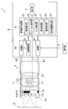
- FIG. 1 is a configuration diagram illustrating a configuration of an endoscope apparatus according to the first embodiment.
- the endoscope apparatus 1 includes an apparatus main body 2 having a function such as a video processor, and an endoscope 3 connected to the apparatus main body 2.
- the apparatus main body 2 includes a display unit 4 such as a liquid crystal panel (LCD) on which an endoscopic image, an operation menu, and the like are displayed.
- the display unit 4 may be provided with a touch panel.
- the endoscope 3 includes an insertion portion 5 as an endoscope insertion portion that is inserted into a subject, an operation portion 6 that is connected to the proximal end of the insertion portion 5, and a universal cord that extends from the operation portion 6. 7.
- the endoscope 3 can be attached to and detached from the apparatus main body 2 via a universal cord 7.
- the insertion portion 5 includes, in order from the distal end side, a distal end portion 11, a bending portion 12 that is connected to the proximal end of the distal end portion 11, for example, can be bent in the vertical and horizontal directions, and the proximal end of the bending portion 12.
- a long flexible portion 13 having flexibility is provided.
- An imaging element 22 such as a CCD sensor or a CMOS sensor is built in the distal end portion 11 of the insertion portion 5.
- An optical adapter 10 that is an optical adapter for an endoscope can be attached to the distal end portion 11. Note that there are a plurality of types of optical adapters 10, and depending on the type to be attached to the distal end portion 11 of the endoscope 3, the viewing angle such as close-up, wide angle, and magnification (telephoto) can be changed, direct view, side view, It is possible to change various optical characteristics such as changing the observation direction such as a perspective view.
- the operation unit 6 is provided with a bending joystick 6a that bends the bending portion 12 in the vertical and horizontal directions. The user can bend the bending portion 12 in a desired direction by tilting the bending joystick 6a.
- the operation unit 6 is provided with buttons for instructing an endoscope function, for example, various operation buttons such as a freeze button, a bending lock button, and a recording instruction button.
- various operation buttons such as a freeze button, a bending lock button, and a recording instruction button.
- the display unit 4 is provided with a touch panel, the user can operate the touch panel to instruct various operations of the endoscope apparatus 1.
- the display unit 4 of the apparatus main body 2 displays an endoscopic image captured by the imaging element 22 of the imaging unit provided in the distal end portion 11.
- various devices such as a control unit 30 (see FIG. 2) that performs image processing and various controls and a recording device that records the processed image are provided inside the apparatus main body 2.
- FIG. 2 is a diagram for explaining the configuration of the optical adapter, the tip portion, and the apparatus main body.
- the optical adapter 10 includes a stereo optical system 10 a configured by two left and right observation optical systems (a first optical system and a second optical system), a mechanical shutter 14, and a coil 15. .
- the stereo optical system 10a is configured to include a left-eye optical system 10L and a right-eye optical system 10R in which an optical axis is disposed in a direction intersecting with the parallax direction and spaced apart from each other in the parallax direction.
- the coil 15 is connected to the control unit 30 of the apparatus main body 2 via the control line 23 when the optical adapter 10 is attached to the distal end portion 11.
- the distal end portion 11 of the insertion portion 5 may have the left eye optical system 10L, the right eye optical system 10R, the mechanical shutter 14, and the coil 15.
- the left eye optical system 10L, the right eye optical system 10R, the mechanical shutter 14 and the coil 15 are arranged at the distal end (the optical adapter 10 or the distal end portion 11) of the insertion portion 5 of the endoscope 3.
- the distal end portion 11 includes an observation optical system 21 and an image sensor 22.
- the imaging element 22 is connected to the video signal processing unit 31 of the apparatus main body 2 via the imaging signal line 24.
- the apparatus main body 2 includes a control unit 30, a video signal processing unit 31, a light source unit 32, and a light source control unit 33.
- the video signal processing unit 31 includes a luminance calculation unit 34, a halation detection unit 35, an edge detection unit 36, a display control unit 37, a motion detection unit 38, and an object distance calculation unit 39. Yes.
- a light guide 25 is inserted through the apparatus main body 2, the endoscope 3, and the optical adapter 10.
- the light source unit 32 is, for example, a xenon lamp, an LED, a laser diode, or the like, and is disposed to face the base end surface of the light guide 25.
- the light source unit 32 is driven under the control of the light source control unit 33 and makes illumination light incident on the base end surface of the light guide 25.
- the illumination light incident on the proximal end surface of the light guide 25 is emitted from the distal end surface of the optical adapter 10, and the subject S is irradiated with the illumination light.
- the light source part 32 is provided in the apparatus main body 2, you may provide in the operation part 6 of the endoscope 3, for example.
- the left-eye optical system 10L, the right-eye optical system 10R, and the observation optical system 21 of the optical adapter 10 are designed so that return light from the subject S irradiated with illumination light is incident on the image sensor 22.
- one observation optical system 21 is provided at the distal end portion 11, but a plurality of observation optical systems are provided at the distal end portion 11, and the left eye optical system 10 ⁇ / b> L and the right eye optical of the optical adapter 10 are provided.
- the return light from the subject S may be incident on the image sensor 22 through the system 10R and the plurality of observation optical systems at the distal end portion 11.
- the mechanical shutter 14 is alternatively arranged with respect to the first position that blocks the optical path passing through the left eye optical system 10L and the second position that blocks the optical path passing through the right eye optical system 10R.
- the mechanical shutter 14 is located at the second position between the right eye optical system 10R and the image sensor 22, so that the light from the right eye optical system 10R is blocked and the left eye optical system.
- the light from 10L is incident on the image sensor 22.
- the operation signal (switching signal) is input to the control unit 30 by operating the operation unit 6 connected to the apparatus main body 2.
- the position of the mechanical shutter 14 may be switched using the touch panel of the display unit 4 of the apparatus main body 2 or the like.
- the control unit 30 causes the coil 15 to generate a magnetic field by causing a current to flow through the coil 15 via the control line 23.
- the mechanical shutter 14 is provided with a magnet (not shown).
- the magnetic field is generated in the coil 15, the mechanical shutter 14 becomes close to the coil 15 due to the magnetic force, and is positioned at the first position between the left eye optical system 10 ⁇ / b> L and the image sensor 22. Thereby, the light from the left eye optical system 10L is shielded, and the light from the right eye optical system 10R enters the image sensor 22.
- the control unit 30 stops supplying the current to the coil 15 via the control line 23 in response to the operation signal, the magnetic field is not generated in the coil 15.
- the mechanical shutter 14 moves to the second position that is the original position, that is, between the right eye optical system 10 ⁇ / b> R and the image sensor 22.
- the coil 15 selects the mechanical shutter 14 that is a shielding unit with respect to the first position that blocks the optical path passing through the left eye optical system 10L and the second position that blocks the optical path passing through the right eye optical system 10R.
- An optical path blocking unit that is disposed in a single block to block any one of the optical paths is configured.
- the imaging element 22 has a light receiving surface arranged at an imaging position of the left eye optical system 10L and the right eye optical system 10R and the observation optical system 21, and receives light through the left eye optical system 10L and the observation optical system 21.
- An imaging signal is generated from at least one of the optical image formed on the surface and the optical image formed on the light receiving surface via the right eye optical system 10R and the observation optical system 21.
- the imaging signal generated by the imaging element 22 is input to the video signal processing unit 31 of the apparatus body 2 via the imaging signal line 24.
- the video signal processing unit 31 generates a video signal related to one of the images corresponding to the left-eye optical system 10L and the images corresponding to the right-eye optical system 10R based on the input imaging signal.
- the generated video signal is input to the display unit 4.
- the display unit 4 displays one of the image corresponding to the left eye optical system 10L and the image corresponding to the right eye optical system 10R.
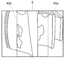
- FIG. 3 is a diagram for explaining the relationship between the subject and the observation ranges of the left eye optical system and the right eye optical system.
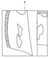
- FIG. 4 is a display image acquired by the left eye optical system and displayed on the display unit.
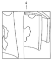
- FIG. 5 is a diagram illustrating an example of a display image acquired by the right eye optical system and displayed on the display unit.
- the left and right eye observation ranges are condensed by the left eye optical system 10L and the right eye optical system 10R, parallax occurs. Therefore, as shown in FIG. 3, the range acquired by the left eye optical system 10L and displayed on the display unit 4 is the observation range 40a, and the range acquired by the right eye optical system 10R and displayed on the display unit 4 becomes the observation range 40b. These observation ranges 40a or 40b are displayed on the display unit 4 as display images.
- the display unit 4 displays an image of the observation range 40a of the left eye optical system 10L as shown in FIG. Is done.
- FIG. 6 is a diagram for explaining an example in which the area of the display image is divided.
- the imaging signal imaged by the imaging element 22 is input to the luminance calculation unit 34 of the video signal processing unit 31 via the imaging signal line 24.
- the luminance calculation unit 34 of the video signal processing unit 31 calculates the luminance value (luminance information) of each pixel of the input imaging signal. Then, as shown in FIG. 6, the luminance calculation unit 34 divides the image into, for example, five areas E1 to E5.
- the upper left of the image is divided into area E1, the upper right of the image is divided into area E2, the lower left of the image is divided into area E3, the lower right of the image is divided into area E4, and the center of the image is divided into area E5.
- the luminance calculation unit 34 calculates an average luminance value for each of the areas E1 to E5 divided in this way.
- the image is divided into five areas E1 to E5.
- the number of divided areas is not limited to five, and may be four or less, or six or more. .
- the halation detection unit 35 of the video signal processing unit 31 compares the average luminance value for each of the areas E1 to E5 calculated by the luminance calculation unit 34 with a predetermined threshold value, and there is an area higher than the predetermined threshold value. In this case, it is determined that halation has occurred in the area. On the other hand, the halation detection unit 35 determines that no halation has occurred when the average luminance value of all the areas E1 to E5 is equal to or less than a predetermined threshold value. The halation detection unit 35 outputs a detection result indicating whether or not halation has occurred to the control unit 30.
- the image is divided into five areas E1 to E5, and the average luminance value of each area E1 to E5 is calculated to detect the occurrence of halation.
- the area is not divided.
- the occurrence of halation may be detected from the luminance value of each pixel of the image.
- the brightness of the portion where halation has occurred in image processing may be suppressed, or the light amount of the light source unit 32 may be suppressed by the light source control unit 33.
- the control unit 30 continues the observation without switching the left and right eye images.
- the control unit 30 determines whether halation is likely to be eliminated by switching the left and right eye images.
- the control unit 30 supplies current to the coil 15 via the control line 23 or stops supplying current.
- the control unit 30 performs a switching process of switching the position of the mechanical shutter 14 and switching the left and right eye images to be displayed on the display unit 4.
- the control unit 30 acquires the right eye optical system 10R.
- the image is switched to the right-eye image, it is determined that there is a high probability that halation will be eliminated. That is, when switching from the left eye image to the right eye image, the halation occurring in the left areas E1 and E3 moves to the left end of the screen or disappears from the screen, so that the visibility of the observation image is improved. To do. Therefore, the control unit 30 determines that there is a high probability that halation will be eliminated.
- control unit 30 determines that the halation is unlikely to be resolved by switching the left and right eye images, the control unit 30 does not switch the left and right eye images, or performs the switching of the left and right eye images. Let the user determine whether
- the control unit 30 acquires the right eye optical system 10R. Even if the image is switched to the right-eye image, it is determined that there is little possibility that halation will be eliminated. That is, when switching from the left-eye image to the right-eye image, the halation occurring in the right areas E2 and E4 moves to the center of the screen, so the visibility of the observation image decreases. Therefore, the control unit 30 determines that there is little possibility that halation will be eliminated.
- control unit 30 determines whether halation is likely to be eliminated by switching the left and right eye images according to the location where the halation has occurred.
- control unit 30 and the video signal processing unit 31 detect the luminance information of one image displayed on the display unit 4 and, when the detected luminance information is higher than a predetermined threshold value, the display unit 4 constitutes a display switching unit that executes a display switching process for switching an image to be displayed from one image to the other image corresponding to the other optical image.
- FIG. 7 is a diagram illustrating an example of a display unit when a left-eye image is displayed
- FIG. 8 is a diagram illustrating an example of a display unit when a right-eye image is displayed.
- the edge detection unit 36 detects the edges of the left and right eye images acquired by the left eye optical system 10L and the right eye optical system 10R.
- the display control unit 37 detects the common part of the left and right eye images from the edges of the left and right eye images detected by the edge detection unit 36. Then, the display control unit 37 controls the display position of the left and right eye images so that the common part of the detected left and right eye images is displayed at the same position in the display area of the display unit 4. More preferably, the display control unit 37 controls the display position of the left and right eye images so that the common part of the left and right eye images, that is, the common subject part is displayed at the center of the display area of the display unit 4. As a result, a sense of incongruity when the left and right eye images are switched is suppressed.
- the display control unit 37 when displaying the left eye image on the display unit 4, the display control unit 37 combines the black image 50 on the right side of the left eye image and displays it on the display unit 4 as shown in FIG. 7. Control. Further, when displaying the right-eye image on the display unit 4, the display control unit 37 combines the black image 51 with the left side of the right-eye image and displays it on the display unit 4 as shown in FIG. 8. Control.
- FIG. 9 is a flowchart for explaining an example of the processing flow of the optical path switching determination.
- the luminance calculation unit 34 calculates the average luminance value of each area of the currently displayed image (step S1).
- the halation detection unit 35 determines whether or not there is an area where the calculated average luminance value is higher than a predetermined threshold (step S2). When there is no area where the average luminance value is higher than the predetermined threshold (S2: NO), the halation detection unit 35 determines that no halation has occurred, and does not execute the display switching process for switching the display of the left and right eye images. The observation is continued (step S3).
- the halation detection unit 35 determines that halation is occurring in the area where the average luminance value is higher than the predetermined threshold (step) S4).
- processing for suppressing halation may be performed by image processing or light source control.
- the display switching process is not executed and the observation is continued.
- the process of the subsequent step S5 is executed.
- the control unit 30 determines whether the area is effective by switching the left and right eye images (step S5). If it is determined that the area is not effective by switching the left and right eye images (S5: NO), the control unit 30 does not execute the display switching process and continues the observation or switches the left and right eye images to the user. Is selected (step S6). On the other hand, when it determines with it being an area which has an effect by switching the image of right and left eyes (S5: YES), the control part 30 performs the display switching process which switches the image of right and left eyes (step S7).
- FIG. 10 is a flowchart for explaining an example of the flow of display switching processing for switching the left and right eye images.
- the images of the left and right eyes are acquired (step S11), and the edges of the acquired images of the left and right eyes are detected (step S12).
- a common part of the left and right eye images is detected from the detected edge (step S13).
- a corrected image is generated so that the detected common part of the left and right eyes is located at the center of the screen of the display unit 4 (step S14).
- a corrected image is generated for the left-eye image.
- a black image is synthesized on the right side of the corrected image for the left eye to generate a display image for the left eye (step S15).
- the generated display image of the left eye is displayed on the display unit 4 (step S16).
- step S17 it is determined whether to switch the image to be displayed from the left eye image to the right eye image. If it is determined to switch from the left-eye image to the right-eye image (S17: YES), a corrected image is generated for the right-eye image.
- the method of generating the corrected image is the same as the method of generating the corrected image of the left eye image, and the correction of the right eye is performed so that the detected common part of the left and right eyes is located at the center of the screen of the display unit 4.
- An image is generated (step S18).
- a black image is synthesized on the left side of the right-eye correction image to generate a right-eye display image (step S19), and the right-eye display image is displayed on the display unit 4 (step S20).
- the right-eye display image is continuously displayed.
- the endoscope apparatus 1 divides an image into, for example, five areas E1 to E5, and detects an area where halation occurs.
- the endoscope apparatus 1 detects whether or not the area has an effect of suppressing halation, and in the case of the effective area, the left and right eye images are switched. Yes. Thereby, the endoscope apparatus 1 can move the generated halation in a direction away from the center of the display screen of the display unit 4 or can erase the halation from the display screen. Get higher.
- the endoscope apparatus of the present embodiment it is possible to suppress a reduction in the visibility of the observation image due to the occurrence of halation.
- the endoscope apparatus 1 controls the display positions of the left and right eye images so that the common part of the left and right eye images is displayed at the same position in the display area of the display unit 4. By doing so, the position of the observation image does not shift even when the left and right eye images are switched, and the uncomfortable feeling when the left and right eye images are switched can be suppressed.
- the left and right eye images are switched at the timing when halation occurs, and if there is an effect, the timing for switching the left and right eye images is not limited to the timing at which halation occurs. Other timings may be used.
- the left and right eye images are acquired using the freeze operation by the user as a trigger, and the display switching process is performed by the control unit 30, or either the left eye image or the right eye image is an image suitable for the user. You may make it select whether there exists.
- the motion detection unit 38 of the video signal processing unit 31 detects a certain motion
- the left and right eye images are acquired, and either the left eye image or the right eye image is an image suitable for the user. You may make it select. That is, the motion detection unit 38 detects the blur amount of the subject based on the imaging signal or the video signal, and when the detected blur amount is larger than a predetermined threshold value, performs the display switching process by the control unit 30 or the left It is selected which of the image of the eye and the image of the right eye is an image suitable for the user.
- the motion detection unit 38 when the motion detection unit 38 does not detect a certain motion, the left and right eye images are acquired, and the left eye image or the right eye image is selected as an image suitable for the user. You may do it. That is, the motion detection unit 38 detects the blur amount of the subject based on the imaging signal or the video signal, and when the detected blur amount is smaller than a predetermined threshold value, performs the display switching process by the control unit 30 or the left It is selected which of the image of the eye and the image of the right eye is an image suitable for the user.
- the left and right eye images are acquired by using the bending lock operation by the user as a trigger, and the display switching process is performed by the control unit 30, or either the left eye image or the right eye image is suitable for the user. You may make it select whether it is an image.
- the freeze button of the operation unit 6, the motion detection unit 38, and the bending lock button of the operation unit 6 constitute a display switching determination unit that outputs trigger information for display switching processing.
- the control unit 30 executes display switching processing based on trigger information from the display switching determination unit.
- the common part of the left and right eye images is detected and arranged at the center of the display screen at the timing of switching the left and right eye images, but the common part of the left and right eye images is detected and the display screen is displayed.
- the timing at which the image is arranged at the center of the image is not limited to the timing for switching the left and right eye images, and may be another timing.
- the control unit 30 executes display switching processing when the type of the optical adapter 10 attached to the distal end portion 11 is changed. That is, when the type of the optical adapter 10 attached to the distal end portion 11 is changed, the control unit 30 detects the common part of the left and right eye images and arranges it at the center of the display screen of the display unit 4. The change of the optical adapter 10 may be detected by the control unit 30 or may be input by the user using the touch panel of the display unit 4.
- FIG. 11 is a flowchart for explaining an example of display image switching processing when the optical adapter is changed.
- FIG. 11 the same processes as those in FIG. 11
- control unit 30 determines whether or not the optical adapter 10 has been changed (step S21). When it determines with the optical adapter 10 not having been changed, it returns to step S21 and repeats the same process. On the other hand, when it determines with the optical adapter 10 having been changed, it progresses to step S11. The processes after step S11 are the same as those in FIG.
- the endoscope apparatus 1 can display an optimal image even when the type of the optical adapter 10 attached to the distal end portion 11 is changed.
- the observation range common to the left and right eyes is changed depending on the object distance between the subject S and the optical adapter 10 or the tip 11. For example, when the distance between the subject S and the optical adapter 10 or the distal end portion 11 decreases, the observation range common to the left and right eyes decreases, and when the distance between the subject S and the optical adapter 10 or the distal end portion 11 increases, The common observation range increases.
- the observation range is changed according to the distance between the subject S and the optical adapter 10 or the distal end portion 11. Therefore, when the object distance is changed, a common part of the left and right eye images may be detected and arranged at the center of the display screen.
- the object distance calculation unit 39 calculates the object distance between the subject S and the optical adapter 10 or the tip 11.
- the object distance between the subject S and the optical adapter 10 or the distal end portion 11 can be measured by acquiring left and right eye images from the left eye optical system 10L and the right eye optical system 10R and using the known triangulation principle. Good.
- the object distance is measured at timings such as a freeze operation using the operation unit 6 described in the second embodiment, a motion detection by the motion detection unit 38, a bending operation using the operation unit 6, and the like. .
- the control unit 30 determines whether or not the object distance calculated by the object distance calculation unit 39 has changed from the previously calculated object distance, and displays when the calculated object distance has changed from the previously calculated object distance. Perform the switching process.
- FIG. 12 is a flowchart for explaining an example of the display image switching process based on the object distance.
- the same processes as those in FIG. 12 are identical processes as those in FIG. 12
- the object distance calculation unit 39 starts object distance measurement (step S31).
- the object distance calculation unit 39 acquires the images of the left and right eyes (step S32), and measures the object distance using a known object distance measurement technique (step S33).
- step S34 determines whether or not the object distance has changed from the previous object distance measurement result. If it is determined from the previous object distance measurement result that the object distance has not changed (S34: NO), the process ends without performing anything. On the other hand, when it is determined that the object distance has changed from the previous object distance measurement result (S34: YES), the process proceeds to step S11.
- the processes after step S11 are the same as those in FIG.
- the endoscope apparatus 1 can display an optimal image even when the distance (object distance) between the subject S and the optical adapter 10 or the distal end portion 11 is changed.
Landscapes
- Health & Medical Sciences (AREA)
- Life Sciences & Earth Sciences (AREA)
- Physics & Mathematics (AREA)
- Surgery (AREA)
- Optics & Photonics (AREA)
- Biomedical Technology (AREA)
- Animal Behavior & Ethology (AREA)
- Radiology & Medical Imaging (AREA)
- Nuclear Medicine, Radiotherapy & Molecular Imaging (AREA)
- Engineering & Computer Science (AREA)
- Biophysics (AREA)
- Heart & Thoracic Surgery (AREA)
- Medical Informatics (AREA)
- Molecular Biology (AREA)
- Pathology (AREA)
- General Health & Medical Sciences (AREA)
- Public Health (AREA)
- Veterinary Medicine (AREA)
- Astronomy & Astrophysics (AREA)
- General Physics & Mathematics (AREA)
- Instruments For Viewing The Inside Of Hollow Bodies (AREA)
- Endoscopes (AREA)
Abstract
内視鏡装置(1)は、内視鏡挿入部と、第1の光学系および第2の光学系を有するステレオ光学系(10a)と、第1の光学系を介して受光面に結像された第1の光学像と、第2の光学系を介して受光面に結像された第2の光学像との少なくとも一方から撮像信号を生成する撮像素子(22)と、第1の画像および第2の画像のうち、一方の画像に関する映像信号を生成する映像信号処理部(31)と、映像信号が入力されることで、一方の画像が表示される表示部(4)と、を有し、さらに、表示部(4)に表示される一方の画像の輝度情報を検出するとともに、検出された輝度情報が所定の閾値よりも高い場合に、表示部(4)に表示する画像を一方の画像から、他方の光学像に対応する他方の画像に切り替える表示切替処理を実行する表示切替部を有する。
Description
本発明は、左右2つの互いに視差を有する観察光学系を備えた内視鏡装置に関するものである。
近年、被検体内に挿入される挿入機器、例えば内視鏡は、医療分野及び工業用分野において広く利用されている。医療分野において用いられる内視鏡は、細長い挿入部を被検体となる体腔内に挿入することによって、体腔内の観察、必要に応じて内視鏡が具備する処置具の挿通チャンネル内に挿入した処置具を用いて各種処置等をすることができる。
また、工業用分野において用いられる内視鏡は、内視鏡の細長い挿入部をジェットエンジン内、工場の配管等の被検体内に挿入することによって、被検体内の被検部位の傷及び腐食等の観察、各種処置、検査等を行うことができる。
また、近年の工業用内視鏡においては、内視鏡の先端部に左右2つの互いに視差を有する観察光学系を備え、左右2つの観察光学系からの観察画像を用いて、三角測量の原理で被写体の様々な空間特性を計測(ステレオ計測)する内視鏡装置が用いられている。例えば、日本国特開2004-187711号公報には、観察画像内に発生するハレーションの影響を低減させて、検査者にとって観察しやすい観察画像を表示させるステレオ計測可能な内視鏡装置が開示されている。
この日本国特開2004-187711号公報に開示されている内視鏡装置は、観察画像内にハレーションが発生しているか否かを判別し、ハレーションが発生している場合、その観察画像に対して画像処理を行う。具体的には、この内視鏡装置は、ハレーションが発生している部分を塗りつぶす、カットする、あるいは、文字情報を表示することでマスク処理を行うようにしている。
これにより、日本国特開2004-187711号公報の内視鏡装置は、ハレーションが発生している表示部分を表示画面から排除することで、検査者が観察画像に対して感じる目障りさを低減することができる。
しかしながら、日本国特開2004-187711号公報の内視鏡装置は、ハレーションが発生している表示部分を表示画面から排除するため、被写体の一部または全部が欠落した画像が表示部に表示されることになり、観察画像の視認性の低下を招くという問題がある。
そこで、本発明は、ハレーション発生による観察画像の視認性の低下を抑制することができる内視鏡装置を提供することを目的とする。
本発明の一態様の内視鏡装置は、内視鏡挿入部と、視差方向に交差する方向に光軸が配置され、前記視差方向に互いに離間して配置された第1の光学系および第2の光学系を有し、前記内視鏡挿入部の先端に配置されるステレオ光学系と、前記先端に配置され、前記第1の光学系および前記第2の光学系の結像位置に配置された受光面を有し、前記第1の光学系を介して前記受光面に結像された第1の光学像と、前記第2の光学系を介して前記受光面に結像された第2の光学像との少なくとも一方から撮像信号を生成する撮像素子と、前記撮像信号に基づいて、前記第1の光学像に対応する第1の画像および前記第2の光学像に対応する第2の画像のうち、一方の画像に関する映像信号を生成する映像信号処理部と、前記映像信号が入力されることで、前記一方の画像が表示される表示部と、を有する内視鏡装置において、前記表示部に表示される前記一方の画像の輝度情報を検出するとともに、検出された前記輝度情報が所定の閾値よりも高い場合に、前記表示部に表示する画像を前記一方の画像から、他方の光学像に対応する他方の画像に切り替える表示切替処理を実行する表示切替部を有する。
以下、図面を参照して本発明の実施形態について詳細に説明する。
(第1の実施形態)
図1は、第1の実施形態に係る内視鏡装置の構成を示す構成図である。
図1は、第1の実施形態に係る内視鏡装置の構成を示す構成図である。
図1に示すように、内視鏡装置1は、ビデオプロセッサ等の機能を備えた装置本体2と、装置本体2に接続される内視鏡3とを有して構成されている。装置本体2は、内視鏡画像、操作メニュー等が表示される、例えば液晶パネル(LCD)等の表示部4を有する。この表示部4には、タッチパネルが設けられていてもよい。
内視鏡3は、被検体内に挿入される内視鏡挿入部としての挿入部5と、挿入部5の基端に連設された操作部6と、操作部6から延出したユニバーサルコード7とを有して構成されている。内視鏡3は、ユニバーサルコード7を介して装置本体2と着脱可能になっている。
挿入部5は、先端側から順に、先端部11と、先端部11の基端に連設された、例えば上下左右方向に湾曲自在に構成された湾曲部12と、湾曲部12に基端に連設された、可撓性を有する長尺な可撓部13とを有して構成されている。
挿入部5の先端部11には、例えばCCDセンサまたはCMOSセンサ等の撮像素子22(図2参照)が内蔵されている。また、先端部11には、内視鏡用光学アダプタである光学アダプタ10が取り付け可能になっている。なお、光学アダプタ10は、複数種類存在するもので、内視鏡3の先端部11に装着する種類に応じて、接写、広角、拡大(望遠)等の視野角の変更、直視、側視、斜視等の観察方向の変更等、種々の光学特性を変えることが可能となっている。
操作部6には、湾曲部12を上下左右方向に湾曲させる湾曲ジョイスティック6aが設けられている。ユーザは、湾曲ジョイスティック6aを傾倒操作することで、湾曲部12を所望の方向に湾曲させることができる。また、操作部6には、湾曲ジョイスティック6aの他に、内視鏡機能を指示するボタン類、例えば、フリーズボタン、湾曲ロックボタン、記録指示ボタン等の各種操作ボタンが設けられている。なお、表示部4にタッチパネルが設けられている構成の場合、ユーザは、タッチパネルを操作して、内視鏡装置1の種々の操作を指示することもできる。
装置本体2の表示部4には、先端部11内に設けられた撮像ユニットの撮像素子22によって撮像された内視鏡画像が表示される。また、装置本体2の内部には、画像処理や各種制御を行う制御部30(図2参照)、処理画像を記録する記録装置等の各種回路が設けられている。
ここで、光学アダプタ10、先端部11、及び、装置本体2の詳細な構成について、図2を用いて説明する。図2は、光学アダプタ、先端部、及び、装置本体の構成を説明するための図である。
図2に示すように、光学アダプタ10は、左右2つの観察光学系(第1の光学系及び第2の光学系)により構成されるステレオ光学系10aと、メカシャッタ14と、コイル15とを備える。ステレオ光学系10aは、視差方向に交差する方向に光軸が配置され、視差方向に互いに離間して配置された左眼光学系10Lと、右眼光学系10Rとを有して構成されている。コイル15は、光学アダプタ10が先端部11に装着された際に、制御線23を介して装置本体2の制御部30に接続される。なお、光学アダプタ10が先端部11に装着されない構成の場合、挿入部5の先端部11が左眼光学系10L、右眼光学系10R、メカシャッタ14及びコイル15を有していればよい。このように、左眼光学系10L、右眼光学系10R、メカシャッタ14及びコイル15が内視鏡3の挿入部5の先端(光学アダプタ10または先端部11)に配置されている。
先端部11は、観察光学系21と、撮像素子22と有して構成されている。撮像素子22は、撮像信号線24を介して装置本体2の映像信号処理部31に接続されている。
装置本体2は、制御部30と、映像信号処理部31と、光源部32と、光源制御部33とを有して構成されている。映像信号処理部31は、輝度算出部34と、ハレーション検知部35と、エッジ検出部36と、表示制御部37と、動き検出部38と、物体距離算出部39とを有して構成されている。また、装置本体2、内視鏡3及び光学アダプタ10内には、ライトガイド25が挿通されている。
光源部32は、例えばキセノンランプ、LED、レーザーダイオード等であり、ライトガイド25の基端面に対向して配置されている。光源部32は、光源制御部33による制御によって駆動し、ライトガイド25の基端面に照明光を入射する。ライトガイド25の基端面に入射された照明光は、光学アダプタ10の先端面から出射され、被写体Sに照明光が照射される。なお、光源部32は、装置本体2に設けられているが、例えば、内視鏡3の操作部6内に設けられていてもよい。
光学アダプタ10の左眼光学系10L及び右眼光学系10Rと観察光学系21とは、照明光が照射された被写体Sからの戻り光を撮像素子22に入射させるように設計されている。なお、図2の例では、先端部11に1つの観察光学系21が設けられているが、先端部11に複数の観察光学系を設け、光学アダプタ10の左眼光学系10L及び右眼光学系10Rと、先端部11の複数の観察光学系とを介して、被写体Sからの戻り光を撮像素子22に入射させるようにしてもよい。
メカシャッタ14は、左眼光学系10Lを通る光路を遮る第1の位置と、右眼光学系10Rを通る光路を遮る第2の位置とに対して択一的に配置される。図2の例では、メカシャッタ14は、右眼光学系10Rと撮像素子22との間の第2の位置に位置しているため、右眼光学系10Rからの光を遮光し、左眼光学系10Lからの光が撮像素子22に入射される状態となっている。
ユーザは、メカシャッタ14の位置を切り替える場合、装置本体2に接続されている操作部6を操作することで、操作信号(切替信号)が制御部30に入力される。なお、メカシャッタ14の位置の切り替えは、装置本体2の表示部4のタッチパネル等を用いて行ってもよい。
制御部30は、操作部6から操作信号が入力されると、制御線23を介してコイル15に電流を流すことでコイル15に磁界を発生させる。メカシャッタ14には図示しない磁石が設けられている。そして、コイル15に磁界が発生すると、メカシャッタ14は、磁力によりコイル15に近づく状態となり、左眼光学系10Lと撮像素子22との間の第1の位置に位置する。これにより、左眼光学系10Lからの光が遮光され、右眼光学系10Rからの光が撮像素子22に入射される状態となる。
制御部30は、操作信号に応じて制御線23を介してコイル15への電流の供給を停止すると、コイル15に磁界が発生しない状態となる。これにより、メカシャッタ14は、元の位置である第2の位置、すなわち右眼光学系10Rと撮像素子22との間に移動する。このように、コイル15は、遮蔽部であるメカシャッタ14を左眼光学系10Lを通る光路を遮る第1の位置と、右眼光学系10Rを通る光路を遮る第2の位置とに対して択一的に配置して、いずれか一方の光路を遮る光路遮断部を構成する。
撮像素子22は、左眼光学系10L及び右眼光学系10Rと観察光学系21との結像位置に配置された受光面を有し、左眼光学系10L及び観察光学系21を介して受光面に結像された光学像と、右眼光学系10R及び観察光学系21を介して受光面に結像された光学像との少なくとも一方から撮像信号を生成する。撮像素子22により生成された撮像信号は、撮像信号線24を介して装置本体2の映像信号処理部31に入力される。
映像信号処理部31は、入力された撮像信号に基づいて、左眼光学系10Lに対応する画像及び右眼光学系10Rに対応する画像のうち、一方の画像に関する映像信号を生成する。生成された映像信号は、表示部4に入力される。表示部4は、映像信号が入力されることで、左眼光学系10Lに対応する画像及び右眼光学系10Rに対応する画像のうち、一方の画像を表示する。
次に、表示部4に表示される表示画像の一例について説明する。図3は、被写体と左眼光学系及び右眼光学系の観察範囲との関係を説明するための図であり、図4は、左眼光学系により取得され、表示部に表示される表示画像の一例を示す図であり、図5は、右眼光学系により取得され、表示部に表示される表示画像の一例を示す図である。
左右眼の観察範囲は、左眼光学系10L及び右眼光学系10Rによりそれぞれ集光しているため視差が発生する。そのため、図3に示すように、左眼光学系10Lにより取得されて表示部4に表示される範囲は、観察範囲40aとなり、右眼光学系10Rにより取得されて表示部4に表示される範囲は、観察範囲40bとなる。これらの観察範囲40aまたは40bが表示画像として表示部4に表示される。
すなわち、右眼光学系10Rと撮像素子22との間にメカシャッタ14が配置されている場合、表示部4には、図4に示すように、左眼光学系10Lの観察範囲40aの画像が表示される。
一方、左眼光学系10Lと撮像素子22との間にメカシャッタ14が配置されている場合、表示部4には、図5に示すように、右眼光学系10Rの観察範囲40bの画像が表示される。
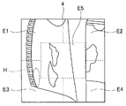
次に、ハレーションの検知について説明する。図6は、表示画像のエリアを分割した一例を説明するための図である。
撮像素子22によって撮像された撮像信号は、撮像信号線24を介して映像信号処理部31の輝度算出部34に入力される。映像信号処理部31の輝度算出部34は、入力された撮像信号の各画素の輝度値(輝度情報)を算出する。そして、輝度算出部34は、図6に示すように、例えば画像を5つのエリアE1~E5に分割する。
図6の例では、画像の左上がエリアE1、画像の右上がエリアE2、画像の左下がエリアE3、画像の右下がエリアE4、画像の中央がエリアE5に分割されている。輝度算出部34は、このように分割された各エリアE1~E5毎の平均輝度値を算出する。なお、図6の例では、画像を5つのエリアE1~E5に分割しているが、分割するエリアは5つに限定されることなく、4つ以下、あるいは、6つ以上であってもよい。
映像信号処理部31のハレーション検知部35は、輝度算出部34によって算出された各エリアE1~E5毎の平均輝度値を予め設定された所定の閾値と比較し、所定の閾値より高いエリアがある場合、そのエリアにおいてハレーションが発生していると判定する。一方、ハレーション検知部35は、全てのエリアE1~E5の平均輝度値が所定の閾値以下の場合、ハレーションが発生していないと判定する。ハレーション検知部35は、ハレーションが発生しているか否かの検知結果を制御部30に出力する。
なお、図6の例では、画像を5つのエリアE1~E5に分割し、各エリアE1~E5の平均輝度値を算出してハレーションの発生を検出しているが、エリアの分割を行わずに、画像の各画素の輝度値からハレーションの発生を検出するようにしてもよい。また、ハレーションが発生していると検知された場合、画像処理でハレーションが発生している部分の明るさを抑えたり、光源制御部33により光源部32の光量を抑えるようにしてもよい。
制御部30は、ハレーション検知部35によってハレーションが発生していないと判定された場合、左右眼の画像を切り替えることなく、そのまま観察を継続する。
また、制御部30は、ハレーション検知部35によってハレーションが発生していると判定された場合、左右眼の画像を切り替えることにより、ハレーションが解消する見込みがあるかを判定する。制御部30は、左右眼の画像を切り替えることでハレーションが解消する見込みがあると判定した場合、制御線23を介してコイル15への電流の供給、あるいは、電流の供給の停止を行う。これにより、制御部30は、メカシャッタ14の位置を切り替え、表示部4に表示させる左右眼の画像を切り替える切替処理を実行する。
例えば、左眼光学系10Lにより取得された左眼の画像で観察している際に、左側のエリアE1、E3でハレーションが発生している場合、制御部30は、右眼光学系10Rにより取得された右眼の画像に切り替えると、ハレーションが解消する見込みが大きいと判断する。すなわち、左眼の画像から右眼の画像に切り替えると、左側のエリアE1、E3で発生しているハレーションが画面のさらに左端に移動する、あるいは、画面から消えるため、観察画像の視認性が向上する。そのため、制御部30は、ハレーションが解消する見込みが大きいと判断する。
一方、制御部30は、左右眼の画像を切り替えることでハレーションが解消する見込みがないと判断した場合、左右眼の画像の切り替えを行わない、あるいは、左右眼の画像の切り替えを実行するか否かをユーザに判断させる。
例えば、左眼光学系10Lにより取得された左眼の画像で観察している際に、右側のエリアE2、E4でハレーションが発生している場合、制御部30は、右眼光学系10Rにより取得された右眼の画像に切り替えても、ハレーションが解消する見込みが少ないと判断する。すなわち、左眼の画像から右眼の画像に切り替えると、右側のエリアE2、E4で発生しているハレーションが画面の中央に移動するため、観察画像の視認性が下がる。そのため、制御部30は、ハレーションが解消する見込みが少ないと判断する。
制御部30は、中央のエリアE5でハレーションが発生している場合、発生している場所に応じて、左右眼の画像を切り替えることにより、ハレーションが解消する見込みがあるかを判定する。
このように、制御部30及び映像信号処理部31は、表示部4に表示される一方の画像の輝度情報を検出するとともに、検出された輝度情報が所定の閾値よりも高い場合に、表示部4に表示する画像を一方の画像から、他方の光学像に対応する他方の画像に切り替える表示切替処理を実行する表示切替部を構成する。
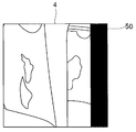
次に、左眼光学系10L及び右眼光学系10Rにより取得された左右眼の画像を切り替えて表示する際の表示例について説明する。図7は、左眼の画像を表示した際の表示部の一例を示す図であり、図8は、右眼の画像を表示した際の表示部の一例を示す図である。
左眼光学系10L及び右眼光学系10Rにより取得された左右眼の画像は視差を有するため、左右眼の画像を切り替えた際に、図4及び図5に示すように、左右眼で共通に撮影している画像の位置が大きくずれてしまい、ユーザに違和感を与えてしまう。
そこで、エッジ検出部36は、左眼光学系10L及び右眼光学系10Rにより取得された左右眼の画像それぞれのエッジを検出する。
表示制御部37は、エッジ検出部36により検出された左右眼の画像のエッジから左右眼の画像の共通部分を検出する。そして、表示制御部37は、検出した左右眼の画像の共通部分を表示部4の表示領域において同じ位置に表示するように、左右眼の画像の表示位置を制御する。より好ましくは、表示制御部37は、左右眼の画像の共通部分、すなわち、共通の被写体部位を表示部4の表示領域の中央に表示するように、左右眼の画像の表示位置を制御する。これにより、左右眼の画像を切り替えた際の違和感を抑えるようにしている。
このように、左右眼の画像の共通部分を表示領域の中央に配置した場合、左眼の画像の右側、及び、右眼の画像の左側に被写体像がない領域存在する。そこで、表示制御部37は、左眼の画像を表示部4に表示する場合、図7に示すように、左眼の画像の右側に黒画像50を合成して表示部4に表示するように制御する。また、表示制御部37は、右眼の画像を表示部4に表示する場合、図8に示すように、右眼の画像の左側に黒画像51を合成して表示部4に表示するように制御する。
次に、このように構成された内視鏡装置1の動作について説明する。
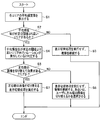
まず、光路切り替え判断の処理について説明する。図9は、光路切り替え判断の処理の流れの一例を説明するためのフローチャートである。
まず、輝度算出部34は、現在表示している画像の各エリアの平均輝度値を算出する(ステップS1)。次に、ハレーション検知部35は、算出した平均輝度値が所定の閾値より高いエリアがあるか否かを判定する(ステップS2)。平均輝度値が所定の閾値より高いエリアがない場合(S2:NO)、ハレーション検知部35は、ハレーションが発生していないと判定し、左右眼の画像の表示を切り替える表示切替処理を実行せず、観察を継続する(ステップS3)。一方、平均輝度値が所定の閾値より高いエリアがある場合(S2:YES)、ハレーション検知部35は、平均輝度値が所定の閾値より高いエリア内でハレーションが発生していると判定する(ステップS4)。
なお、ハレーションが発生していると判定した場合、上述したように、画像処理や光源制御によりハレーションを抑える処理を行ってもよい。その結果、平均輝度値が所定の閾値より高いエリアがなくなった場合、表示切替処理を実行せず、観察を継続する。一方、ハレーションを抑える処理を行っても、ハレーションが発生している場合、続くステップS5の処理を実行する。
次に、ハレーションが発生していると判定されると、制御部30は、左右眼の画像を切り替えて効果があるエリアか否かを判定する(ステップS5)。左右眼の画像を切り替えて効果があるエリアでないと判定した場合(S5:NO)、制御部30は、表示切替処理を実行せず、観察を継続する、あるいは、ユーザに左右眼の画像を切り替えるかを選択させる(ステップS6)。一方、左右眼の画像を切り替えて効果があるエリアであると判定した場合(S5:YES)、制御部30は、左右眼の画像を切り替える表示切替処理を実行する(ステップS7)。
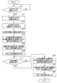
次に、図9のステップS7の左右眼の画像を切り替える表示切替処理について説明する。図10は、左右眼の画像を切り替える表示切替処理の流れの一例を説明するためのフローチャートである。
まず、左右眼それぞれの画像を取得し(ステップS11)、取得した左右眼の画像のそれぞれのエッジを検出する(ステップS12)。検出したエッジから左右眼の画像の共通部分を検出する(ステップS13)。検出した左右眼の共通部分が表示部4の画面中央に位置するように、補正画像を生成する(ステップS14)。なお、ここではデフォルトとして左眼の画像を表示させようとしているため、左眼の画像について補正画像を生成することになる。次に左眼の補正画像の右側に黒画像を合成し、左眼の表示画像を生成する(ステップS15)。そして、生成した左眼の表示画像を表示部4に表示する(ステップS16)。
次に、表示する画像を左眼の画像から右眼の画像に切り替えるか否かを判定する(ステップS17)。左眼の画像から右眼の画像に切り替えると判定した場合(S17:YES)、右眼の画像について補正画像を生成する。補正画像の生成のしかたについては、左眼の画像の補正画像の生成の仕方と同様であって、検出した左右眼の共通部分が表示部4の画面中央に位置するように、右眼の補正画像を生成する(ステップS18)。そして、右眼の補正画像の左側に黒画像を合成し、右眼の表示画像を生成し(ステップS19)、右眼の表示画像を表示部4に表示する(ステップS20)。
なお、左眼の画像から右眼の画像に切り替えないと判定した場合(S15:NO)、右眼の表示画像を表示し続ける。
以上のように、内視鏡装置1は、画像を例えば5つのエリアE1~E5に分割し、ハレーションが発生しているエリアを検出する。そして、内視鏡装置1は、左右眼の画像を切り替えた際に、ハレーションを抑制する効果があるエリアか否かを検出し、効果があるエリアの場合、左右眼の画像を切り替えるようにしている。これにより、内視鏡装置1は、発生しているハレーションを表示部4の表示画面の中央から離れる方向に移動する、あるいは、表示画面から消すことができるため、ユーザにとって観察画像の視認性が高くなる。
よって、本実施形態の内視鏡装置によれば、ハレーション発生による観察画像の視認性の低下を抑制することができる。
また、内視鏡装置1は、左右眼の画像を切り替える際に、左右眼の画像の共通部分を表示部4の表示領域の同じ位置に表示するように、左右眼の画像の表示位置を制御することにより、左右眼の画像を切り替えた際にも観察画像の位置がずれることなくなり、左右眼の画像を切り替えた際の違和感を抑えることができる。
(第2の実施形態)
次に、第2の実施形態について説明する。第1の実施形態では、ハレーションが発生したタイミングで、効果がある場合は左右眼の画像を切り替えていたが、左右眼の画像を切り替えるタイミングは、ハレーションが発生したタイミングに限定されることはなく、他のタイミングであってもよい。
次に、第2の実施形態について説明する。第1の実施形態では、ハレーションが発生したタイミングで、効果がある場合は左右眼の画像を切り替えていたが、左右眼の画像を切り替えるタイミングは、ハレーションが発生したタイミングに限定されることはなく、他のタイミングであってもよい。
ユーザが操作部6のフリーズボタンを押下し、フリーズ操作をした場合、その観察箇所を詳細に検査したい可能性が高い。そこで、ユーザによるフリーズ操作をトリガーにして左右眼の画像を取得し、制御部30による表示切替処理を行う、あるいは、左眼の画像と右眼の画像のいずれの画像がユーザに適した画像であるかを選択させるようにしてもよい。
また、映像信号処理部31の動き検出部38が一定の動きを検出した場合、左右眼の画像を取得し、左眼の画像と右眼の画像のいずれの画像がユーザに適した画像であるかを選択させるようにしてもよい。すなわち、動き検出部38は、撮像信号あるいは映像信号に基づいて、被写体のぶれ量を検出し、検出したぶれ量が所定の閾値より大きい場合、制御部30による表示切替処理を行う、あるいは、左眼の画像と右眼の画像のいずれの画像がユーザに適した画像であるかを選択させる。
また、動き検出部38が一定の動きを検出していない場合、左右眼の画像を取得し、左眼の画像と右眼の画像のいずれの画像がユーザに適した画像であるかを選択させるようにしてもよい。すなわち、動き検出部38は、撮像信号あるいは映像信号に基づいて、被写体のぶれ量を検出し、検出したぶれ量が所定の閾値より小さい場合、制御部30による表示切替処理を行う、あるいは、左眼の画像と右眼の画像のいずれの画像がユーザに適した画像であるかを選択させる。
また、ユーザが操作部6の湾曲ロックボタンを押下し、湾曲ロック操作をした場合、その観察箇所を詳細に検査したい可能性が高い。そこで、ユーザによる湾曲ロック操作をトリガーにして左右眼の画像を取得し、制御部30による表示切替処理を行う、あるいは、左眼の画像と右眼の画像のいずれかの画像がユーザに適した画像であるかを選択させるようにしてもよい。
以上のように、操作部6のフリーズボタン、動き検出部38、及び、操作部6の湾曲ロックボタンが表示切替処理のトリガー情報を出力する表示切替判断部を構成する。制御部30は、表示切替判断部からのトリガー情報に基づいて、表示切替処理を実行する。
(第3の実施形態)
次に、第3の実施形態について説明する。
次に、第3の実施形態について説明する。
第1の実施形態では、左右眼の画像を切り替えるタイミングで左右眼の画像の共通部分を検出し、表示画面の中央に配置していたが、左右眼の画像の共通部分を検出し、表示画面の中央に配置するタイミングは、左右眼の画像を切り替えるタイミングに限定されることなく、他のタイミングであってもよい。
先端部11に装着される光学アダプタ10の種類が変更された場合、光学アダプタ10の画角等の光学特性が変更されるため、左右眼の観察範囲が変更される。そこで、制御部30は、先端部11に装着される光学アダプタ10の種類が変更された際に、表示切替処理を実行する。すなわち、制御部30は、先端部11に装着される光学アダプタ10の種類が変更された際に、左右眼の画像の共通部分を検出し、表示部4の表示画面の中央に配置する。なお、光学アダプタ10の変更の検知は、制御部30によって行ってもよいし、ユーザが表示部4のタッチパネルを用いて入力してもよい。
図11は、光学アダプタの変更時の表示画像の切替処理の一例を説明するためのフローチャートである。なお、図11において、図10と同様の処理については、同一の符号を付して説明を省略する。
まず、制御部30は、光学アダプタ10が変更されたか否かを判定する(ステップS21)。光学アダプタ10が変更されていないと判定した場合、ステップS21に戻り、同様の処理を繰り返す。一方、光学アダプタ10が変更されたと判定した場合、ステップS11に進む。ステップS11以降の処理は、図10と同様である。
以上の処理により、内視鏡装置1は、先端部11に装着される光学アダプタ10の種類が変更された場合でも最適な画像を表示することができる。
(第4の実施形態)
次に、第4の実施形態について説明する。
次に、第4の実施形態について説明する。
被写体Sと光学アダプタ10あるいは先端部11との物体距離により、左右眼で共通となる観察範囲が変更される。例えば、被写体Sと光学アダプタ10あるいは先端部11との距離が近くなると、左右眼の共通する観察範囲は少なくなり、被写体Sと光学アダプタ10あるいは先端部11との距離が遠くなると、左右眼の共通する観察範囲は多くなる。
このように、被写体Sと光学アダプタ10あるいは先端部11との距離に応じて観察範囲が変更される。そこで、物体距離が変更された際に、左右眼の画像の共通部分を検出し、表示画面の中央に配置するようにしてもよい。
測定部としての物体距離算出部39は、被写体Sと光学アダプタ10あるいは先端部11との物体距離を算出する。なお、被写体Sと光学アダプタ10あるいは先端部11との物体距離は、左眼光学系10L及び右眼光学系10Rから左右眼の画像を取得し、公知の三角測量の原理を用いて測定すればよい。また、物体距離を測定するタイミングは、例えば、第2の実施形態で説明した操作部6を用いたフリーズ操作、動き検出部38による動き検出、操作部6を用いた湾曲操作等のタイミングで行う。
制御部30は、物体距離算出部39により算出された物体距離が前回算出された物体距離から変わったか否かを判定し、算出された物体距離が前回算出された物体距離から変わった場合、表示切替処理を実行する。
図12は、物体距離による表示画像の切替処理の一例を説明するためのフローチャートである。なお、図12において、図10と同様の処理については、同一の符号を付して説明を省略する。
まず、物体距離算出部39は、物体距離測定を開始する(ステップS31)。物体距離算出部39は、左右眼それぞれの画像を取得し(ステップS32)、公知の物体距離測定技術を用い、物体距離を測定する(ステップS33)。
次に、制御部30は、前回の物体距離測定結果から物体距離が変わったか否かを判定する(ステップS34)。前回の物体距離測定結果から物体距離が変わっていないと判定した場合(S34:NO)、何も行わずに処理を終了する。一方、前回の物体距離測定結果から物体距離が変わったと判定した場合(S34:YES)、ステップS11に進む。ステップS11以降の処理は、図10と同様である。
以上の処理により、内視鏡装置1は、被写体Sと光学アダプタ10あるいは先端部11との距離(物体距離)が変更された場合でも最適な画像を表示することができる。
本発明は、上述した実施形態に限定されるものではなく、本発明の要旨を変えない範囲において、種々の変更、改変等が可能である。
本出願は、2016年9月9日に日本国に出願された特願2016-176262号を優先権主張の基礎として出願するものであり、上記の開示内容は、本願明細書、請求の範囲に引用されるものとする。
Claims (13)
- 内視鏡挿入部と、
視差方向に交差する方向に光軸が配置され、前記視差方向に互いに離間して配置された第1の光学系および第2の光学系を有し、前記内視鏡挿入部の先端に配置されるステレオ光学系と、
前記先端に配置され、前記第1の光学系および前記第2の光学系の結像位置に配置された受光面を有し、前記第1の光学系を介して前記受光面に結像された第1の光学像と、前記第2の光学系を介して前記受光面に結像された第2の光学像との少なくとも一方から撮像信号を生成する撮像素子と、
前記撮像信号に基づいて、前記第1の光学像に対応する第1の画像および前記第2の光学像に対応する第2の画像のうち、一方の画像に関する映像信号を生成する映像信号処理部と、
前記映像信号が入力されることで、前記一方の画像が表示される表示部と、を有する内視鏡装置において、
前記表示部に表示される前記一方の画像の輝度情報を検出するとともに、検出された前記輝度情報が所定の閾値よりも高い場合に、前記表示部に表示する画像を前記一方の画像から、他方の光学像に対応する他方の画像に切り替える表示切替処理を実行する表示切替部を有することを特徴とする内視鏡装置。 - さらに、前記第1の光学系を通る光路を遮る第1の位置と、前記第2の光学系を通る光路を遮る第2の位置とに対して択一的に遮蔽部を配置することで、いずれか一方の光路を遮る光路遮断部を有し、
前記表示切替部は、前記一方の画像から前記他方の画像に切り替える場合、前記遮蔽部の配置位置を現在の位置から他方の位置へ切り替えることを特徴とする請求項1に記載の内視鏡装置。 - 前記表示切替部は、前記一方の画像を複数の画像領域に分割し、前記複数の画像領域毎に前記輝度情報を検出することを特徴とする請求項1に記載の内視鏡装置。
- 前記表示切替部は、前記所定の閾値よりも高い前記輝度情報が検出された画像領域を計数し、
計数値が前記所定の閾値を超える場合に、前記表示部に表示する画像を、前記一方の画像から、前記他方の光学像に対応する他方の画像に切り替えることを特徴とする請求項3に記載の内視鏡装置。 - さらに、前記表示切替処理のトリガー情報を出力する表示切替判断部を有し、
前記表示切替部は、前記表示切替判断部からの前記トリガー情報に基づいて、前記表示切替処理を実行することを特徴とする請求項1に記載の内視鏡装置。 - 前記表示切替判断部は、検査者による静止画表示処理を検出した場合、前記トリガー情報を出力することを特徴とする請求項5に記載の内視鏡装置。
- 前記表示切替判断部は、前記撮像信号あるいは前記映像信号に基づいて、被写体のぶれ量を検出し、当該ぶれ量が前記所定の閾値よりも小さいと判断した場合、前記トリガー情報を出力することを特徴とする請求項5に記載の内視鏡装置。
- 前記表示切替判断部は、検査者による湾曲ロック操作指示を検出した場合、前記トリガー情報を出力することを特徴とする請求項5に記載の内視鏡装置。
- さらに、前記表示部の表示領域に対して、前記一方の画像と前記他方の画像とを表示する位置を制御する表示制御部を有し、
前記表示制御部は、前記一方の画像と前記他方の画像とに共通で表示される被写体部位が、前記一方の画像が表示されるときと前記他方の画像が表示されるときとで、前記表示部の表示領域において同じ位置に表示されるように、各画像の表示位置を制御することを特徴とする請求項1に記載の内視鏡装置。 - 前記表示制御部は、前記被写体部位が、前記表示部の表示領域の中央に表示されるように、各画像の表示位置を制御することを特徴とする請求項9に記載の内視鏡装置。
- 前記表示制御部は、前記第1の光学系および前記第2の光学系の光学特性に基づいて、各画像の表示位置を制御することを特徴とする請求項9に記載の内視鏡装置。
- さらに、被写体との物体距離を測定する測定部を有し、
前記表示制御部は、前記測定部によって測定された物体距離に基づいて、各画像の表示位置を制御することを特徴とする請求項9に記載の内視鏡装置。 - 前記表示制御部は、前記表示部の前記表示領域の全面に前記一方の画像を表示させた場合の前記被写体部位の表示位置と、前記表示領域の全面に前記他方の画像を表示させた場合の前記被写体部位の表示位置との距離に対して、前記表示部の前記表示領域の一部に前記一方の画像を表示させた場合の前記被写体部位の表示位置と、前記表示領域の一部とは異なる表示位置に前記他方の画像を表示させた場合の前記被写体部位の表示位置との距離が小さくなるように、各画像を表示することを特徴とする請求項10に記載の内視鏡装置。
Priority Applications (1)
| Application Number | Priority Date | Filing Date | Title |
|---|---|---|---|
| JP2018538258A JP6694964B2 (ja) | 2016-09-09 | 2017-07-14 | 内視鏡装置 |
Applications Claiming Priority (2)
| Application Number | Priority Date | Filing Date | Title |
|---|---|---|---|
| JP2016176262 | 2016-09-09 | ||
| JP2016-176262 | 2016-09-09 |
Publications (1)
| Publication Number | Publication Date |
|---|---|
| WO2018047465A1 true WO2018047465A1 (ja) | 2018-03-15 |
Family
ID=61562116
Family Applications (1)
| Application Number | Title | Priority Date | Filing Date |
|---|---|---|---|
| PCT/JP2017/025661 Ceased WO2018047465A1 (ja) | 2016-09-09 | 2017-07-14 | 内視鏡装置 |
Country Status (2)
| Country | Link |
|---|---|
| JP (1) | JP6694964B2 (ja) |
| WO (1) | WO2018047465A1 (ja) |
Cited By (2)
| Publication number | Priority date | Publication date | Assignee | Title |
|---|---|---|---|---|
| CN114269218A (zh) * | 2019-08-29 | 2022-04-01 | 奥林巴斯株式会社 | 图像处理方法和图像处理装置 |
| WO2024188160A1 (zh) * | 2023-03-13 | 2024-09-19 | 武汉迈瑞生物医疗科技有限公司 | 用于内窥镜系统的成像及显示方法和内窥镜系统 |
Citations (3)
| Publication number | Priority date | Publication date | Assignee | Title |
|---|---|---|---|---|
| JPH0662438A (ja) * | 1992-08-14 | 1994-03-04 | Olympus Optical Co Ltd | 立体像観察システム |
| JP2004187711A (ja) * | 2002-12-06 | 2004-07-08 | Olympus Corp | 内視鏡装置 |
| JP2014028008A (ja) * | 2012-07-31 | 2014-02-13 | Olympus Corp | ステレオ計測装置およびステレオ計測方法 |
-
2017
- 2017-07-14 JP JP2018538258A patent/JP6694964B2/ja active Active
- 2017-07-14 WO PCT/JP2017/025661 patent/WO2018047465A1/ja not_active Ceased
Patent Citations (3)
| Publication number | Priority date | Publication date | Assignee | Title |
|---|---|---|---|---|
| JPH0662438A (ja) * | 1992-08-14 | 1994-03-04 | Olympus Optical Co Ltd | 立体像観察システム |
| JP2004187711A (ja) * | 2002-12-06 | 2004-07-08 | Olympus Corp | 内視鏡装置 |
| JP2014028008A (ja) * | 2012-07-31 | 2014-02-13 | Olympus Corp | ステレオ計測装置およびステレオ計測方法 |
Cited By (2)
| Publication number | Priority date | Publication date | Assignee | Title |
|---|---|---|---|---|
| CN114269218A (zh) * | 2019-08-29 | 2022-04-01 | 奥林巴斯株式会社 | 图像处理方法和图像处理装置 |
| WO2024188160A1 (zh) * | 2023-03-13 | 2024-09-19 | 武汉迈瑞生物医疗科技有限公司 | 用于内窥镜系统的成像及显示方法和内窥镜系统 |
Also Published As
| Publication number | Publication date |
|---|---|
| JP6694964B2 (ja) | 2020-05-20 |
| JPWO2018047465A1 (ja) | 2019-03-07 |
Similar Documents
| Publication | Publication Date | Title |
|---|---|---|
| US11555997B2 (en) | Endoscope with integrated measurement of distance to objects of interest | |
| JP5284731B2 (ja) | 立体画像撮影表示システム | |
| JP6323184B2 (ja) | 画像処理装置、画像処理方法、並びにプログラム | |
| US11426052B2 (en) | Endoscopic system | |
| JP5996319B2 (ja) | ステレオ計測装置およびステレオ計測装置の作動方法 | |
| JP6150955B2 (ja) | 立体視内視鏡装置およびビデオプロセッサ | |
| CN104185441B (zh) | 立体视觉内窥镜系统 | |
| US20120300032A1 (en) | Endoscope | |
| US20120130168A1 (en) | Endoscope apparatus | |
| WO2020008672A1 (ja) | 内視鏡システム | |
| WO2006118057A1 (ja) | 画像表示装置 | |
| JP4801641B2 (ja) | タッチパネル及び内視鏡装置のプロセッサ | |
| JP6694964B2 (ja) | 内視鏡装置 | |
| JPH11318936A (ja) | 手術用顕微鏡装置 | |
| JP2014175965A (ja) | 手術用カメラ | |
| JP2016095458A (ja) | 内視鏡装置 | |
| US11224329B2 (en) | Medical observation apparatus | |
| JP5792401B2 (ja) | オートフォーカス装置 | |
| JPWO2016181781A1 (ja) | 内視鏡装置 | |
| JP4246510B2 (ja) | 立体内視鏡システム | |
| JP7375022B2 (ja) | 画像処理装置の作動方法、制御装置、および内視鏡システム | |
| JP4464103B2 (ja) | 画像表示システム | |
| JP2018007837A (ja) | 画像処理装置 | |
| CN116322560A (zh) | 医用图像处理装置及医用观察系统 | |
| JP2017038933A (ja) | ステレオ計測用画像取得装置及びステレオ計測用画像取得装置の作動方法 |
Legal Events
| Date | Code | Title | Description |
|---|---|---|---|
| ENP | Entry into the national phase |
Ref document number: 2018538258 Country of ref document: JP Kind code of ref document: A |
|
| 121 | Ep: the epo has been informed by wipo that ep was designated in this application |
Ref document number: 17848410 Country of ref document: EP Kind code of ref document: A1 |
|
| NENP | Non-entry into the national phase |
Ref country code: DE |
|
| 122 | Ep: pct application non-entry in european phase |
Ref document number: 17848410 Country of ref document: EP Kind code of ref document: A1 |