WO2018043709A1 - 加速器、加速器の運転方法および加速器を用いた半導体の製造方法 - Google Patents
加速器、加速器の運転方法および加速器を用いた半導体の製造方法 Download PDFInfo
- Publication number
- WO2018043709A1 WO2018043709A1 PCT/JP2017/031582 JP2017031582W WO2018043709A1 WO 2018043709 A1 WO2018043709 A1 WO 2018043709A1 JP 2017031582 W JP2017031582 W JP 2017031582W WO 2018043709 A1 WO2018043709 A1 WO 2018043709A1
- Authority
- WO
- WIPO (PCT)
- Prior art keywords
- output
- frequency
- unit
- charged particle
- particle beam
- Prior art date
- Legal status (The legal status is an assumption and is not a legal conclusion. Google has not performed a legal analysis and makes no representation as to the accuracy of the status listed.)
- Ceased
Links
Images


Classifications
-
- G—PHYSICS
- G03—PHOTOGRAPHY; CINEMATOGRAPHY; ANALOGOUS TECHNIQUES USING WAVES OTHER THAN OPTICAL WAVES; ELECTROGRAPHY; HOLOGRAPHY
- G03F—PHOTOMECHANICAL PRODUCTION OF TEXTURED OR PATTERNED SURFACES, e.g. FOR PRINTING, FOR PROCESSING OF SEMICONDUCTOR DEVICES; MATERIALS THEREFOR; ORIGINALS THEREFOR; APPARATUS SPECIALLY ADAPTED THEREFOR
- G03F7/00—Photomechanical, e.g. photolithographic, production of textured or patterned surfaces, e.g. printing surfaces; Materials therefor, e.g. comprising photoresists; Apparatus specially adapted therefor
- G03F7/20—Exposure; Apparatus therefor
-
- H—ELECTRICITY
- H05—ELECTRIC TECHNIQUES NOT OTHERWISE PROVIDED FOR
- H05H—PLASMA TECHNIQUE; PRODUCTION OF ACCELERATED ELECTRICALLY-CHARGED PARTICLES OR OF NEUTRONS; PRODUCTION OR ACCELERATION OF NEUTRAL MOLECULAR OR ATOMIC BEAMS
- H05H13/00—Magnetic resonance accelerators; Cyclotrons
- H05H13/04—Synchrotrons
-
- H—ELECTRICITY
- H05—ELECTRIC TECHNIQUES NOT OTHERWISE PROVIDED FOR
- H05H—PLASMA TECHNIQUE; PRODUCTION OF ACCELERATED ELECTRICALLY-CHARGED PARTICLES OR OF NEUTRONS; PRODUCTION OR ACCELERATION OF NEUTRAL MOLECULAR OR ATOMIC BEAMS
- H05H7/00—Details of devices of the types covered by groups H05H9/00, H05H11/00, H05H13/00
- H05H7/14—Vacuum chambers
- H05H7/18—Cavities; Resonators
-
- H—ELECTRICITY
- H05—ELECTRIC TECHNIQUES NOT OTHERWISE PROVIDED FOR
- H05H—PLASMA TECHNIQUE; PRODUCTION OF ACCELERATED ELECTRICALLY-CHARGED PARTICLES OR OF NEUTRONS; PRODUCTION OR ACCELERATION OF NEUTRAL MOLECULAR OR ATOMIC BEAMS
- H05H9/00—Linear accelerators
Definitions
- Embodiments of the present invention relate to an accelerator including a high-frequency cavity.
- Conventional accelerators have a high-frequency cavity that can change the speed of the incident charged particle beam.
- a fundamental wave having a predetermined frequency is generated inside a high-frequency cavity using a high-frequency source, and a charged particle beam is caused to enter the inside of the high-frequency cavity at a period of 1 / integer of the frequency of the fundamental wave. The incident is repeated.
- a higher-order mode having a higher frequency than the fundamental wave frequency used for changing the speed of the charged particle beam may occur.
- This higher-order mode is generated because the electromagnetic wave generated by the charged particle beam resonates inside the high-frequency cavity. If this higher-order mode coincides with the incident period of the charged particle beam, electromagnetic waves that become noise accumulate inside the high-frequency cavity, causing a problem that the high-frequency cavity generates heat.
- the embodiment of the present invention has been made in view of such circumstances, and an object thereof is to provide an accelerator technique capable of suppressing heat generation in a high-frequency cavity.
- An accelerator includes a high-frequency cavity through which a charged particle beam can pass, a high-frequency source that inputs an electromagnetic wave having a fundamental frequency into the high-frequency cavity, a laser output unit that outputs laser light, and the laser light
- a target unit that generates charged particles by irradiation
- a beam extraction unit that extracts a charged particle beam by accelerating the charged particles in one direction, and a specific one of the timings corresponding to the period of the fundamental frequency
- an output control unit that performs control to output the charged particle beam toward the high-frequency cavity at a timing.
- An accelerator operation method includes a high frequency input step of inputting an electromagnetic wave having a fundamental frequency from a high frequency source to a high frequency cavity, a laser output step of outputting laser light from a laser output unit, and the laser light as a target.
- an accelerator technology capable of suppressing heat generation in the high-frequency cavity is provided.
- Reference numeral 1 in FIG. 1 denotes an accelerator for accelerating the charged particle beam B.
- this accelerator 1 has illustrated the linear accelerator which accelerates the charged particle beam B on a straight line.
- the accelerator 1 generates a high-frequency cavity 2 through which the charged particle beam B can pass, a high-frequency source 3 that inputs a radio frequency (RF) that is an electromagnetic wave having a fundamental frequency into the high-frequency cavity 2, and a charged particle beam B. And a main control unit 5 that controls the high-frequency source 3 and the beam generator 4.
- RF radio frequency
- FIG. 1 a simplified configuration is shown to help understanding, but devices other than these devices may be included in the accelerator 1.
- the high frequency cavity 2 includes a plurality of cavity chambers 6 each having a shape in which a sphere is flattened. These hollow chambers 6 are arranged side by side along the traveling direction of the charged particle beam B. Further, the central portion of the cavity chamber 6 is penetrated, and a path through which the charged particle beam B can pass is formed linearly.
- the high frequency incident on the inside of the high frequency cavity 2 is repeatedly reflected according to the internal shape of the cavity chamber 6.
- a fundamental wave (standing wave) is generated inside the high-frequency cavity 2.
- a high frequency source 3 is connected to the end of the high frequency cavity 2 via an RF input unit 7.
- the high frequency source 3 inputs an electromagnetic wave K having a fundamental frequency (high frequency K) into the high frequency cavity 2.
- the high frequency source 3 includes a high frequency controller 8 that controls the high frequency K input to the high frequency cavity 2.
- the high frequency control unit 8 includes a frequency setting unit 9 that sets a basic frequency. As will be described later, the frequency setting unit 9 performs a setting for increasing the fundamental frequency in accordance with the rate at which the pulses of the laser light L are selected within a predetermined period.
- the high frequency cavity 2 receives a high frequency K from the high frequency source 3 to generate a fundamental wave (standing wave) therein.
- the frequency of the fundamental wave generated inside the high frequency cavity 2 is controlled by the frequency of the high frequency K input from the high frequency source 3.
- the beam generator 4 repeatedly enters the charged particle beam B into the high frequency cavity 2 with a period of 1 / integer of the frequency of the fundamental wave.
- the speed of the incident charged particle beam B is accelerated by appropriately changing the timing of incidence of the charged particle beam B with respect to the standing wave of the high frequency cavity 2 or the phase of the high frequency K with respect to the incident timing of the charged particle beam B. You can slow down or slow down.
- the high-frequency cavity 2 since the high frequency cavity 2 generates heat when a fundamental wave is generated, a metal material having high thermal conductivity and low electrical resistance is suitable.
- the high-frequency cavity 2 is made of a superconducting material such as a niobium material.
- the niobium material includes niobium alone, an alloy of niobium and another metal (such as copper).
- the high-frequency cavity 2 is cooled to a very low temperature (about 2K) by a cooling device (not shown). In this way, the cooled high-frequency cavity 2 is transferred to a superconducting state in which the electric resistance becomes zero as much as possible. By changing the high frequency cavity 2 to the superconducting state, the speed of the charged particle beam B can be changed with high efficiency.
- the beam generation device 4 accelerates the charged particles generated in the target 11 in one direction, the laser output unit 10 that outputs the laser light L, the target 11 that generates charged particles when irradiated with the laser light L, and the target 11.
- the extraction electrode 12 for extracting the charged particle beam B, the DC power source 13 connected to the target 11 and the extraction electrode 12, the laser output unit 10 and the target 11 are provided with the laser light L.
- the light modulation part 14 which can be interrupted
- the extraction electrode 12 is a beam extraction portion.
- the laser beam L output from the laser output unit 10 is applied to the target 11. Then, charged particles are generated at the target 11. The generated charged particles are accelerated in one direction by the extraction electrode 12 and become a charged particle beam B and enter the high-frequency cavity 2.
- the main control unit 5 is connected to the high frequency control unit 8 and the output control unit 15 to control the high frequency source 3 and the beam generator 4.
- the main control unit 5, the output control unit 15, and the high-frequency control unit 8 have hardware resources such as a processor and a memory, and the CPU executes various programs, so that information processing by software uses the hardware resources. It is comprised with the computer implement
- the charged particle beam B incident on the high-frequency cavity 2 from the beam generator 4 is a pulse train beam (pulse wave). Further, the output control unit 15 controls the timing of the output of the charged particle beam B by controlling the timing at which the target 11 is irradiated with the laser light L. In the present embodiment, the charged particle beam B is output at a timing corresponding to the period of the fundamental frequency of the fundamental wave generated inside the high frequency cavity 2.
- the higher order mode (HOM: Higher Order Mode) generated inside the high frequency cavity 2 will be described in detail.
- the frequency component of the high frequency (fundamental wave) existing inside the high frequency cavity 2 is ideally only the frequency of the high frequency K input from the high frequency source 3.
- acceleration / deceleration of the charged particle beam B is realized by transferring high-frequency energy stored in the high-frequency cavity 2 between the high-frequency cavity 2 and the charged particle beam B. Therefore, when the charged particle beam B is accelerated or decelerated, the high frequency inside the high frequency cavity 2 is disturbed.
- a frequency component different from the high frequency K input from the high frequency source 3 may be generated in the high frequency cavity 2.
- the time change of the current of the pulse train of the charged particle beam B can be regarded as a periodic ⁇ function.
- This has a frequency component that is an integral multiple of the fundamental frequency when Fourier transform is performed.
- This is a frequency component of the disturbance that the high frequency stored in the high frequency cavity 2 receives.
- the only high-frequency frequencies that can resonate inside are the fundamental wave and its integral multiples.
- the actual internal shape of the high-frequency cavity 2 has a three-dimensional shape, it has various resonance frequencies in addition to the fundamental frequency.
- the frequency component of the electromagnetic field generated inside the high-frequency cavity 2 is called a higher-order mode.
- the beam incident on the high-frequency cavity 2 has a frequency that is 1 / integer of the fundamental frequency.
- the acceleration or deceleration of the charged particle beam B is the transfer of energy with the high-frequency cavity 2. Since this transferred energy has a frequency due to the charged particle beam B, the higher-order mode of the high-frequency cavity 2 may coincide with one of the frequency components of the charged particle beam B.
- electromagnetic waves that become noise accumulate inside the high-frequency cavity 2 and the high-frequency cavity 2 may generate heat. This heat generation may cause a deformation of the high-frequency cavity 2 and a cause of a superconducting state break (quenching).
- the charged particle beam B to be accelerated next is disturbed by electromagnetic waves that become noise, and may be adversely affected such as not being normally accelerated or the shape of the charged particle beam B being destroyed.
- the frequency component of the charged particle beam B is dispersed or attenuated by selecting (randomly thinning out) the pulse train of the charged particle beam B incident on the high frequency cavity 2 at non-constant intervals. Like that. In this way, generation of higher order modes can be suppressed, and heat generation in the high frequency cavity 2 can be suppressed.
- the beam generator 4 outputs the charged particle beam B toward the high-frequency cavity 2 at a selected specific timing out of a fixed interval corresponding to the period of the fundamental frequency.
- the pulse train of the charged particle beam B is selected by selecting the pulse train of the laser light L using the light modulator 14. That is, the selection of the laser beam L and the selection of the charged particle beam B are synonymous.
- the output control unit 15 of the beam generating device 4 has a ratio setting unit 16 that sets a ratio at which a pulse of the laser light L is selected within a predetermined period, and a constant interval period (tuning timing) that is tuned to the period of the fundamental frequency.
- the tuning unit 17 that outputs the tuning signal U, the signal output unit 18 that outputs the trigger signal G that triggers the laser output unit 10 to output the laser light L, and a random number with a periodic interval that is tuned to the cycle of the fundamental frequency
- the random number output part 19 which outputs R, and the selection part 20 which outputs the selection signal S which controls the optical modulation part 14 are provided.
- the optical modulation unit 14 of the first embodiment is configured by an optical switch.
- An optical switch is a device that can switch light passage (ON) or blocking (OFF).
- an EO modulator is used as the optical switch.
- the EO modulator is a device that controls the deflection of light by electrical control and changes the intensity of light by combining an electro-optic crystal and a polarizer.
- a MEMS optical switch, a mechanical optical switch, or the like may be used as another embodiment.
- the light modulator 14 switches between passing (ON) and blocking (OFF) of the laser light L traveling toward the target 11.
- the optical path between the laser output unit 10 and the target 11 may be constituted by an optical fiber or the like. In this manner, the output timing of the charged particle beam B is controlled by controlling the irradiation timing of the laser beam L to the target 11.
- the signal output unit 18 controls the output of the trigger signal G according to the tuning signal U (tuning timing) output from the tuning unit 17. Furthermore, the selection unit 20 controls the output of the selection signal S according to the tuning signal U output from the tuning unit 17 and the random number R output from the random number output unit 19.
- the period of the constant interval that is tuned to the period of the fundamental frequency may be the same period as the fundamental frequency or may be a period of an integral number of the fundamental frequency.
- the output timing of the tuning signal U output from the tuning unit 17 is the same as the period of the fundamental frequency.
- the period of the fundamental frequency of the high frequency K input from the high frequency source 3 to the high frequency cavity 2 is T1 to T20.
- the tuning unit 17 of the output control unit 15 outputs the tuning signal U at a timing that coincides with the fundamental frequency periods T1 to T20.
- the signal output unit 18 outputs a trigger signal G according to the tuning signal U.
- the pulse train of the laser light L at the time when the laser output unit 10 outputs coincides with the fundamental frequency periods T1 to T20.
- the tuning signal U is also input to the selection unit 20.
- the random number R output from the random number output unit 19 is input to the selection unit 20.
- the random number R is a random (irregular) value of a binary number.
- a predetermined random number sequence is generated by a random number generator.
- the random number output unit 19 randomly outputs a numerical value “0” or “1”. A random value in decimal or hexadecimal may be output, and the output value may be converted to “0” or “1” to output a random number sequence.
- the random number R output from the random number output unit 19 is output corresponding to the tuning signal U (periods T1 to T20 of the fundamental frequency).
- the selection unit 20 controls the output of the selection signal S according to the tuning signal U and the random number R. Based on the selection signal S, the light modulator 14 controls the passage (ON) and blocking (OFF) of the laser light L. For example, when the tuning signal U is input and the random number R corresponding to the tuning signal U is “0”, the selection unit 20 uses the light modulation unit 14 to block the laser light L. On the other hand, when the random number R corresponding to the tuning signal U is “1”, the selection unit 20 does not block the laser light L using the light modulation unit 14 and allows the laser light L to pass therethrough.
- the laser beam L blocked by the light modulation unit 14 is not irradiated to the target 11.
- the laser light L not blocked by the light modulation unit 14 is irradiated onto the target 11 to generate a charged particle beam B, and this charged particle beam B is incident on the high-frequency cavity 2.
- the irradiation timing of the laser beam L is the irradiation timing of the laser beam L, and the output timing of the charged particle beam B is controlled by the random number R of the random number output unit 19. Since the irradiation timing of the laser light L is determined according to the random number R, the pulse train of the charged particle beam B incident on the high frequency cavity 2 can be selected at non-constant intervals. In this way, since the charged particle beam B is output at non-constant intervals, it is possible to prevent the generation of higher-order modes inside the high-frequency cavity 2.
- the interval between the irradiation timing of one laser beam L and the irradiation timing of the next laser beam L is not constant, and is appropriately changed according to the random number R. That is, in the present embodiment, the interval between the timing at which one charged particle beam B is output and the timing at which the next charged particle beam B is output can be changed. In this way, the timing at which the repeated charged particle beam B is output is shifted, so that the resonance phenomenon inside the high-frequency cavity 2 can be prevented.
- the ratio setting unit 16 sets in advance a ratio at which the irradiation timing of the laser light L is selected within a predetermined period.
- the random number output unit 19 sets the appearance mode of the random number R in accordance with the selection ratio set by the ratio setting unit 16. For example, when 50% of the irradiation timing of the laser light L is selected, the appearance probability of “0” in the random number R output from the random number output unit 19 may be set to 50%. Note that the ratio of selecting the irradiation timing of the laser light L within a predetermined period may be changed as appropriate.
- the average current (average energy) of the charged particle beam B decreases. Therefore, in order to obtain the target average current, it is necessary to increase the fundamental frequency by an amount that takes into account the proportion selected beforehand.
- the current component of the pulse train of the charged particle beam B incident on the high-frequency cavity 2 at a specific repetition frequency has a frequency component concentrated on an integral multiple of this frequency. From the Wiener Hinchin's theorem, the spectrum of the modulation received by the charged particle beam B is expressed by the following Equation 1.
- C (t) is an expected value of the autocorrelation function when the beam current is a signal sequence.
- the signal sequence P (t) is expressed by the following Equation 2.
- Equation 3 the expected value of autocorrelation is expressed by Equation 3 below.
- Equation 4 Equation 4 below.
- the frequency component becomes smaller than the frequency f0 when the present invention is not applied.
- the frequency of f1 is 1.3 GHz
- the frequency of f0 is 650 MHz, which is a half frequency of f1.
- the frequency components of f0 are 650 MHz, 1.3 GHz, 1.95 GHz, 2.6 GHz, 3.25 GHz, 3.9 GHz, and so on.
- the frequency components of f1 are 1.3 GHz, 2.6 GHz, 3.9 GHz,.
- f1 has fewer frequency components than f0. Therefore, by increasing the fundamental frequency f1, the possibility (probability) that a resonance phenomenon occurs inside the high-frequency cavity 2 can be reduced.
- the output control unit 15 sets the selection rate W of the irradiation timing of the laser light L by the rate setting unit 16 in accordance with the control information C input from the main control unit 5. Further, the ratio setting unit 16 outputs the set selection ratio W to the frequency setting unit 9 of the high frequency control unit 8. The selection ratio is also output to the random number output unit 19. Furthermore, the frequency setting unit 9 sets a basic frequency according to the selection ratio W.
- the high frequency control unit 8 performs control by outputting a control signal N to the high frequency source 3 based on the set fundamental frequency.
- the frequency setting unit 9 outputs the frequency information F of the set basic frequency to the ratio setting unit 16. Further, the ratio setting unit 16 outputs the frequency information F to the tuning unit 17 and the random number output unit 19. Then, the tuning unit 17 and the random number output unit 19 output a tuning signal U and a random number R based on the frequency information F.
- the output control unit 15 can select these timings at random by selecting the irradiation timing of the laser light L based on the random number R output from the random number output unit 19.
- the frequency setting unit 9 performs setting to increase the fundamental frequency in accordance with the ratio at which the irradiation timing of the laser light L is selected within a predetermined period, so that the average energy of the charged particle beam B output from the high-frequency cavity 2 Can be prevented from being reduced.
- a pulse of a specific laser beam L can be selected by appropriately blocking the laser beam L output at a constant interval by the light modulator 14. Furthermore, by using the light modulation unit 14, the timing at which the charged particle beam B is output can be selected with a simple configuration.
- the beam generator 4 may be an electron gun that outputs an electron beam in a beam shape.
- the target 11 is a photocathode part and the extraction electrode 12 is an anode part. Then, photoelectrons as charged particles are generated by the photoelectric effect generated by irradiating the target 11 (cathode unit) with the laser beam L output from the laser output unit 10. By appropriately selecting the generation timing of the photoelectrons as described above, an electron gun that can suppress the heat generation of the high-frequency cavity 2 can be obtained.
- the beam generator 4 may be an ion source that outputs positive ions in a beam shape.
- the target 11 is an ion target part
- the extraction electrode 12 is a cathode part. Then, positive ions as charged particles are generated by the ablation plasma generated by irradiating the target 11 (ion target unit) with the laser light L output from the laser output unit 10.
- an ion source that can suppress the heat generation of the high-frequency cavity 2 can be obtained.
- Step S11 a portion described as “Step S11” is abbreviated as “S11”.
- the frequency setting unit 9 of the high frequency control unit 8 sets the basic frequency based on the selection ratio W input from the ratio setting unit 16 of the output control unit 15 (S11).
- the high frequency controller 8 controls the high frequency source 3 to input the high frequency K (electromagnetic wave K) of the fundamental frequency into the high frequency cavity 2 (S12: high frequency input step).
- the tuning unit 17 and the random number output unit 19 of the output control unit 15 perform tuning timing (period of the basic frequency) for causing the laser light L to enter the high frequency cavity 2 based on the basic frequency set by the frequency setting unit 9. Is acquired (S13).
- the tuning unit 17 outputs the tuning signal U to the signal output unit 18 at a timing that matches the tuning timing.
- the signal output unit 18 to which the tuning signal U is input outputs the trigger signal G to the laser output unit 10 at the tuning timing (S14).
- the laser output unit 10 to which the trigger signal G is input outputs the laser light L at the tuning timing (S15: laser output step).
- the selection unit 20 acquires a random number R corresponding to the tuning timing from the random number output unit 19 (S16).
- the selection unit 20 controls the light modulation unit 14 based on the acquired random number R, and selects a pulse of the laser beam L at a specific timing among the tuning timings corresponding to the period of the fundamental frequency (S17: Output control step).
- charged particles are generated by irradiating the target 11 with the laser beam L at a specific timing (S18: particle generation step).
- the extraction electrode 12 extracts the charged particle beam B by accelerating the charged particles in one direction, and the charged particle beam B is output from the beam generator 4 (S19: beam extraction step).
- the charged particle beam B passes through the high-frequency cavity 2 (S20: passage step).
- an output high-frequency cavity 21 is provided instead of the extraction electrode 12 of the first embodiment.
- the output high-frequency cavity 21 is a beam extraction portion.
- the light modulator 14 selects the pulse of the laser light L.
- the pulse of the laser light L is selected depending on whether or not the trigger signal G is output.
- the output high-frequency cavity 21 is provided at a position close to the target 11.
- a high frequency source 23 is connected to an end of the output high frequency cavity 21 via an RF input unit 22.
- the output high-frequency cavity 21 extracts the charged particle beam B by accelerating the charged particles generated on the target 11 in one direction.
- the charged particle beam B drawn out by the output high-frequency cavity 21 is incident on the main high-frequency cavity 2.
- the output high-frequency cavity 21 is controlled by a control signal N output from the output high-frequency controller 24. Further, the ratio setting unit 16 of the output control unit 15A outputs the frequency information F to the tuning unit 17 and the random number output unit 19, and also outputs the frequency information F to the frequency setting unit 25 of the output high-frequency control unit 24.
- the frequency setting unit 25 sets a fundamental frequency based on the frequency information F. Then, the output high frequency controller 24 inputs the high frequency K from the high frequency source 23 to the high frequency cavity 2 based on the set fundamental frequency.
- the selection unit 20 of the output control unit 15A of the second embodiment inputs the selection signal S to the signal output unit 18.
- the signal output unit 18 outputs the trigger signal G at a specific timing according to the selection signal S output from the selection unit 20. That is, the selection unit 20 selects the output timing of the trigger signal G at non-constant intervals. Then, the laser light L is output from the laser output unit 10 at a specific timing of the tuning timing that is a constant interval period that is tuned to the period of the fundamental frequency.
- the period of the fundamental frequency of the high frequency K input from the high frequency source 3 to the high frequency cavity 2 is T1 to T20.
- the tuning unit 17 of the output control unit 15A outputs the tuning signal U to the signal output unit 18 and the selection unit 20 at a timing that coincides with the fundamental frequency periods T1 to T20.
- the random number R output from the random number output unit 19 is output corresponding to the tuning signal U (periods T1 to T20 of the fundamental frequency).
- the random number R is input to the selection unit 20.
- the selection unit 20 outputs a selection signal S to the signal output unit 18 according to the tuning signal U and the random number R. For example, when the tuning signal U is input and the random number R corresponding to the tuning signal U is “0”, the selection unit 20 outputs a selection signal S indicating that the trigger signal G is not output to the signal output unit 18. Output to. On the other hand, when the random number R corresponding to the tuning signal U is “1”, the selection signal S for outputting the trigger signal G is output to the signal output unit 18.
- the signal output unit 18 controls whether the trigger signal G is output according to the tuning signal U input from the tuning unit 17 and the selection signal S input from the selection unit 20.
- the laser output unit 10 outputs a laser beam L according to the trigger signal G output from the signal output unit 18.
- the laser beam L output from the laser output unit 10 is irradiated onto the target 11 to generate a charged particle beam B, and the charged particle beam B is incident on the high-frequency cavity 2.
- the output timing of the laser beam L and the output timing of the charged particle beam B are controlled by the random number R of the random number output unit 19. Since the output timing of the laser beam L is determined according to the random number R, the pulse train of the charged particle beam B incident on the high frequency cavity 2 can be selected at non-constant intervals. In this way, since the charged particle beam B is output at non-constant intervals, it is possible to prevent the generation of higher-order modes inside the high-frequency cavity 2.
- the timing at which the charged particle beam B is output can be selected with a simple configuration.
- the beam generator 4A of the second embodiment may be an electron gun having the target 11 as a photocathode part or an ion source having the target 11 as an ion target part.
- the frequency setting unit 9 of the high frequency control unit 8 sets the basic frequency based on the selection ratio W input from the ratio setting unit 16 of the output control unit 15A (S21).
- the high frequency control unit 8 controls the high frequency source 3 to input the high frequency K (electromagnetic wave K) of the fundamental frequency into the high frequency cavity 2 (S22: high frequency input step).
- the tuning unit 17 and the random number output unit 19 of the output control unit 15A have tuning timing (period of the basic frequency) for causing the laser light L to enter the high frequency cavity 2 based on the basic frequency set by the frequency setting unit 9. Is acquired (S23).
- the selection unit 20 acquires a random number R corresponding to the tuning timing from the random number output unit 19 (S24). Then, the selection unit 20 outputs a selection signal S to the signal output unit 18 in accordance with the tuning signal U and the random number R.
- the signal output unit 18 selects a pulse of the trigger signal G at a specific timing among the tuning timings corresponding to the period of the fundamental frequency based on the selection signal S input from the selection unit 20 (S25: Output control step).
- the signal output unit 18 outputs the trigger signal G to the laser output unit 10 at a specific timing (S26).
- the laser output unit 10 to which the trigger signal G is input outputs the laser light L at a specific timing (S27: laser output step).
- charged particles are generated by irradiating the target 11 with the laser beam L at a specific timing (S28: Particle generation step).
- the output high-frequency cavity 21 extracts the charged particle beam B by accelerating the charged particles in one direction, and the charged particle beam B is output from the beam generator 4A (S29: beam extraction step).
- the charged particle beam B passes through the high frequency cavity 2 (S30: passage step).
- the configuration applied in any one of the embodiments may be applied to other embodiments, or each embodiment.
- the configurations applied in may be combined.
- the extraction electrode 12 of the first embodiment may be applied to the beam generator 4A of the second embodiment
- the output high-frequency cavity 21 of the second embodiment is applied to the beam generator 4 of the first embodiment. You may do it.
- a linear accelerator is illustrated as an accelerator to which the present invention is applied.
- the present invention may be applied to a circular accelerator such as a cyclotron or a synchrotron.
- a circular accelerator such as a cyclotron or a synchrotron.
- a circular accelerator is an accelerator that uses this to accelerate charged particles while drawing a circular start-up.
- the accelerator 1 (1A) of the present embodiment can be used for a semiconductor manufacturing apparatus (an ion implantation apparatus for manufacturing a semiconductor).
- the semiconductor manufacturing method using the accelerator of the present embodiment includes an irradiation step of irradiating a predetermined substrate (semiconductor) with the charged particle beam B after the above-described passing step of S20 or S30.
- the substrate By irradiating the substrate with the charged particle beam B (ions) that has passed through the high-frequency cavity 2, the ions are implanted into the substrate.
- an element such as boron, phosphorus or arsenic is ionized, and the ions are accelerated by an accelerator and implanted into a substrate such as silicon, gallium arsenide, silicon carbide, or a polysilicon thin film on the surface of a glass plate.
- a substrate such as silicon, gallium arsenide, silicon carbide, or a polysilicon thin film on the surface of a glass plate.
- the accelerator 1 (1A) of the present embodiment can be used in a semiconductor manufacturing apparatus (semiconductor manufacturing lithography).
- the charged particle beam B (electrons) is irradiated with a predetermined undulator (N poles and S poles alternately arranged) after the passing step of S20 or S30 described above.
- a predetermined undulator N poles and S poles alternately arranged
- a lithography step for performing lithography of the semiconductor circuit with the generated light.
- a high-power light can be generated from the charged particle beam B (electrons) with a high current that has passed through the high-frequency cavity 2.
- the light generation by the undulator can freely select the wavelength. Therefore, EUV (Extreme Ultraviolet Lithography) lithography using a shorter wavelength light, for example, 13.5 nm extreme ultraviolet light can be performed, and a semiconductor circuit having a finer circuit line width can be manufactured. Become.
- the output control unit that performs control to output the charged particle beam toward the high-frequency cavity at a specific timing corresponding to the period of the fundamental frequency, heat generation of the high-frequency cavity is achieved. Can be suppressed.
- DESCRIPTION OF SYMBOLS 1 (1A) ... Accelerator, 2 ... High frequency cavity, 3 ... High frequency source, 4 (4A) ... Beam generator, 5 ... Main control part, 6 ... Cavity room, 7 ... RF input part, 8 ... High frequency control part, 9 DESCRIPTION OF SYMBOLS ... Frequency setting part, 10 ... Laser output part, 11 ... Target part, 12 ... Extraction electrode, 13 ... DC power supply, 14 ... Light modulation part, 15 (15A) ... Output control part, 16 ... Ratio setting part, 17 ... Tuning , 18 ... signal output unit, 19 ... random number output unit, 20 ... selection unit, 21 ... high frequency cavity for output, 22 ... RF input unit, 23 ... high frequency source, 24 ... high frequency control unit for output, 25 ... frequency setting unit .
Landscapes
- Physics & Mathematics (AREA)
- Engineering & Computer Science (AREA)
- Plasma & Fusion (AREA)
- Spectroscopy & Molecular Physics (AREA)
- General Physics & Mathematics (AREA)
- Particle Accelerators (AREA)
- Exposure And Positioning Against Photoresist Photosensitive Materials (AREA)
Abstract
加速器(1)は、荷電粒子ビーム(B)が通過可能な高周波空洞(2)と、基本周波数の電磁波を高周波空洞(2)に入力する高周波源(3)と、レーザ光(L)を出力するレーザ出力部(10)と、レーザ光(L)が照射されることで荷電粒子を発生させるターゲット部(11)と、荷電粒子を一方向に加速することで荷電粒子ビーム(B)を引き出すビーム引出部(12)と、基本周波数の周期に対応するタイミングのうちの特定のタイミングで荷電粒子ビーム(B)を高周波空洞(2)に向けて出力する制御を行う出力制御部(15)とを備える。
Description
本発明の実施形態は、高周波空洞を備える加速器に関する。
従来の加速器は、入射される荷電粒子ビームの速度を変更可能な高周波空洞を備える。このような加速器では、高周波源を用いて高周波空洞の内部に所定の周波数の基本波を生じさせるとともに、この基本波の周波数の整数分の1の周期で、荷電粒子ビームを高周波空洞の内部に繰り返し入射させるようにしている。
高周波空洞では、荷電粒子ビームの速度変更に用いる基本波の周波数よりも、周波数が高い高次モード(HOM)が生じる場合がある。この高次モードは、荷電粒子ビームが発生させる電磁波が高周波空洞の内部で共振を起こすために生じる。この高次モードが荷電粒子ビームの入射周期と一致してしまうと、高周波空洞の内部にノイズとなる電磁波が溜まってしまい、高周波空洞が発熱してしまうという課題がある。
本発明の実施形態はこのような事情を考慮してなされたもので、高周波空洞の発熱を抑えることができる加速器技術を提供することを目的とする。
本発明の実施形態に係る加速器は、荷電粒子ビームが通過可能な高周波空洞と、基本周波数の電磁波を前記高周波空洞に入力する高周波源と、レーザ光を出力するレーザ出力部と、前記レーザ光が照射されることで荷電粒子を発生させるターゲット部と、前記荷電粒子を一方向に加速することで荷電粒子ビームを引き出すビーム引出部と、前記基本周波数の周期に対応するタイミングのうちの特定の前記タイミングで前記荷電粒子ビームを前記高周波空洞に向けて出力する制御を行う出力制御部と、を備えることを特徴とする。
本発明の実施形態に係る加速器の運転方法は、基本周波数の電磁波を高周波源から高周波空洞に入力する高周波入力ステップと、レーザ出力部からレーザ光を出力するレーザ出力ステップと、前記レーザ光がターゲット部に照射されることで荷電粒子を発生させる粒子発生ステップと、前記荷電粒子を一方向に加速することで荷電粒子ビームを引き出すビーム引出ステップと、前記基本周波数の周期に対応するタイミングのうちの特定の前記タイミングで前記荷電粒子ビームを前記高周波空洞に向けて出力する制御を行う出力制御ステップと、前記荷電粒子ビームが前記高周波空洞を通過する通過ステップと、を含むことを特徴とする。
本発明の実施形態により、高周波空洞の発熱を抑えることができる加速器技術が提供される。
(第1実施形態)
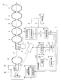
以下、本実施形態を添付図面に基づいて説明する。まず、第1実施形態について図1から図3を用いて説明する。図1の符号1は、荷電粒子ビームBを加速するための加速器である。なお、この加速器1は、荷電粒子ビームBを一直線上で加速する線形加速器を例示している。
以下、本実施形態を添付図面に基づいて説明する。まず、第1実施形態について図1から図3を用いて説明する。図1の符号1は、荷電粒子ビームBを加速するための加速器である。なお、この加速器1は、荷電粒子ビームBを一直線上で加速する線形加速器を例示している。
また、加速器1は、荷電粒子ビームBが通過可能な高周波空洞2と、基本周波数の電磁波である高周波(RF:Radio Frequency)を高周波空洞2に入力する高周波源3と、荷電粒子ビームBを発生させるビーム発生装置4と、高周波源3とビーム発生装置4とを制御する主制御部5とを備える。なお、図1では、理解を助けるために、簡略化した構成を示しているが、これらの装置以外の装置が、加速器1に含まれても良い。
また、高周波空洞2は、球体が扁平に潰れた形状を成す複数の空洞室6を備える。これらの空洞室6が荷電粒子ビームBの進行方向に沿って並んで配置されている。さらに、空洞室6の中央部が貫通され、荷電粒子ビームBが通過可能な経路が直線状に形成される。なお、高周波空洞2の内部に入射される高周波は、空洞室6の内部形状に応じて反射を繰り返す。そして、高周波空洞2の内部に基本波(定在波)が生じるようになっている。
さらに、高周波空洞2の端部には、RF入力部7を介して高周波源3が接続されている。また、高周波源3は、基本周波数の電磁波K(高周波K)を高周波空洞2に入力する。なお、高周波源3は、高周波空洞2に入力する高周波Kの制御を行う高周波制御部8を備える。この高周波制御部8は、基本周波数の設定を行う周波数設定部9を備える。この周波数設定部9は、後述するように、所定期間内にレーザ光Lのパルスが選抜される割合に応じて基本周波数を高める設定を行う。
また、高周波空洞2は、高周波源3から高周波Kを入力されることで、その内部に基本波(定在波)を生じさせる。なお、高周波空洞2の内部に生じる基本波の周波数は、高周波源3から入力される高周波Kの周波数により制御される。
また、ビーム発生装置4は、基本波の周波数の整数分の1の周期で、荷電粒子ビームBを高周波空洞2の内部に繰り返し入射させるようにしている。なお、高周波空洞2の定在波に対する荷電粒子ビームBの入射のタイミング、または荷電粒子ビームBの入射タイミングに対する高周波Kの位相を適宜変更することにより、入射される荷電粒子ビームBの速度を加速したり減速したりすることができる。
また、高周波空洞2は、基本波を発生させると発熱するため、熱伝導率が大きく電気抵抗が小さい金属材料が適している。この高周波空洞2は、ニオブ材などの超電導材料で構成される。なお、ニオブ材には、ニオブ単体とニオブと他の金属(銅など)との合金が含まれる。そして、高周波空洞2は、冷却装置(図示略)により極低温(約2K)に冷却される。このように、冷却された高周波空洞2は、電気抵抗が限りなくゼロになる超伝導状態に転移される。高周波空洞2を超電導状態にすることで、高効率で荷電粒子ビームBの速度の変更を行えるようにしている。
また、ビーム発生装置4は、レーザ光Lを出力するレーザ出力部10と、レーザ光Lが照射されることで荷電粒子を発生させるターゲット11と、ターゲット11で発生した荷電粒子を一方向に加速することで荷電粒子ビームBを引き出すための引き出し電極12と、ターゲット11と引き出し電極12とに接続される直流電源13と、レーザ出力部10とターゲット11との間に設けられてレーザ光Lを遮断可能な光変調部14と、レーザ出力部10と光変調部14とを制御する出力制御部15とを備える。なお、第1実施形態では、引き出し電極12が、ビーム引出部となっている。
また、レーザ出力部10から出力されたレーザ光Lは、ターゲット11に照射される。そして、ターゲット11にて荷電粒子が発生する。そして、発生した荷電粒子は、引き出し電極12により一方向に加速され、荷電粒子ビームBとなって高周波空洞2に入射される。
なお、主制御部5は、高周波制御部8および出力制御部15に接続され、高周波源3およびビーム発生装置4を制御している。なお、主制御部5や出力制御部15や高周波制御部8は、プロセッサやメモリなどのハードウエア資源を有し、CPUが各種プログラムを実行することで、ソフトウエアによる情報処理がハードウエア資源を用いて実現されるコンピュータで構成される。
また、ビーム発生装置4から高周波空洞2に入射される荷電粒子ビームBは、パルス列のビーム(パルス波)となっている。さらに、出力制御部15は、レーザ光Lがターゲット11に照射されるタイミングを制御することで、荷電粒子ビームBの出力のタイミングを制御している。本実施形態では、高周波空洞2の内部で生じている基本波の基本周波数の周期に対応するタイミングで荷電粒子ビームBが出力される。
ここで、高周波空洞2の内部に生じる高次モード(HOM:Higher Order Mode)について詳述する。例えば、高周波空洞2の内部に存在する高周波(基本波)の周波数成分は、高周波源3から入力される高周波Kの周波数のみであることが理想的である。しかし、荷電粒子ビームBの加減速は、高周波空洞2に貯められた高周波のエネルギーが、高周波空洞2と荷電粒子ビームBとの間で授受されることで実現される。そのため、荷電粒子ビームBの加減速の際に、高周波空洞2の内部の高周波が擾乱を受ける。そして、高周波源3から入力される高周波Kとは、異なる周波数成分が高周波空洞2の内部に生まれる場合がある。
例えば、荷電粒子ビームBのパルス列の電流の時間変化は、周期的δ関数とみなせる。これはフーリエ変換を行うと、基本周波数の整数倍の周波数成分を有する。これが高周波空洞2に貯められた高周波が受ける擾乱の周波数成分となる。
理想的な高周波空洞2であれば、その内部で共振し得る高周波の周波数は、基本波とその整数倍の周波数のみである。一方、現実の高周波空洞2の内部形状は、3次元的な形状を有するために、基本周波数以外にも様々な共振周波数を有する。これらの基本モード以外に高周波空洞2の内部に生じる電磁場の周波数成分が、高次モードと呼ばれる。
前述したとおり、高周波空洞2に入射するビームは、基本周波数の整数分の1の周波数を有する。そして、荷電粒子ビームBの加速または減速は、高周波空洞2とのエネルギーの授受である。この授受されるエネルギーは、荷電粒子ビームBに起因する周波数を持つため、高周波空洞2の高次モードが、荷電粒子ビームBが持つ周波数成分のいずれかと一致してしまう場合がある。この場合に、高周波空洞2の内部にノイズとなる電磁波が溜まってしまい、高周波空洞2が発熱してしまうことがある。この発熱が、高周波空洞2の変形や、超伝導状態の破れ(クエンチ)の要因となるおそれがある。また、ノイズとなる電磁波により、次に加速される荷電粒子ビームBが擾乱を受け、正常に加速されない、或いは荷電粒子ビームBの形状が崩れるなどの悪影響を受ける場合がある。
そこで、本実施形態では、高周波空洞2に入射される荷電粒子ビームBのパルス列を一定ではない間隔で選抜する(無作為に間引く)ことで、荷電粒子ビームBが持つ周波数成分を分散または減衰させるようにする。このようにすれば、高次モードの発生が抑えられ、高周波空洞2の発熱を抑えることができる。
なお、ビーム発生装置4は、基本周波数の周期に対応する一定間隔のタイミングのうちの選抜された特定のタイミングで荷電粒子ビームBを高周波空洞2に向けて出力する。第1実施形態では、光変調部14を用いてレーザ光Lのパルス列を選抜することで、荷電粒子ビームBのパルス列を選抜している。つまり、レーザ光Lの選抜と荷電粒子ビームBの選抜とが同義である。
ここで、ビーム発生装置4が出力する荷電粒子ビームBの出力態様について詳述する。ビーム発生装置4の出力制御部15は、所定期間内にレーザ光Lのパルスが選抜される割合を設定する割合設定部16と、基本周波数の周期に同調する一定間隔の周期(同調タイミング)で同調信号Uを出力する同調部17と、レーザ出力部10がレーザ光Lを出力する契機となるトリガ信号Gを出力する信号出力部18と、基本周波数の周期に同調する一定間隔の周期で乱数Rを出力する乱数出力部19と、光変調部14を制御する選抜信号Sを出力する選抜部20とを備える。
また、第1実施形態の光変調部14は、光スイッチで構成される。なお、光スイッチとは、光の通過(ON)または遮断(OFF)を切り換えることができるデバイスである。第1実施形態では、光スイッチとしてEОモジュレータが用いられる。なお、EOモジュレータは、電気制御で光の偏向制御を行い、電気光学結晶と偏光子を組み合わせて光の強弱を変化させるデバイスである。また、他の実施形態としてMEMS式の光スイッチや、機械式の光スイッチなどを用いても良い。
第1実施形態では、光変調部14が、ターゲット11に向かって進行するレーザ光Lの通過(ON)または遮断(OFF)を切り換えるようにしている。なお、レーザ出力部10とターゲット11との間の光路は、光ファイバなどにより構成されても良い。このように、ターゲット11に対するレーザ光Lの照射タイミングが制御されることで、荷電粒子ビームBの出力タイミングが制御される。
なお、信号出力部18は、同調部17から出力される同調信号U(同調タイミング)に応じてトリガ信号Gの出力を制御する。さらに、選抜部20は、同調部17から出力される同調信号Uおよび乱数出力部19から出力される乱数Rに応じて選抜信号Sの出力を制御する。
また、基本周波数の周期に同調する一定間隔の周期とは、基本周波数と同一周期であっても良いし、基本周波数の整数分の1の周期であっても良い。なお、以下の説明では、理解を助けるために、同調部17から出力される同調信号Uの出力タイミングが、基本周波数の周期と同一であるものとして説明する。
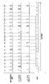
図2に示すように、高周波源3から高周波空洞2に入力される高周波Kの基本周波数の周期をT1~T20とする。これらの周期T1~T20に一致したタイミングで、荷電粒子ビームBが高周波空洞2に入射されると、荷電粒子ビームBの加減速を行うことができる。ここで、出力制御部15の同調部17は、基本周波数の周期T1~T20に一致したタイミングで同調信号Uを出力する。また、信号出力部18は、同調信号Uに応じてトリガ信号Gを出力する。そして、レーザ出力部10が出力した時点のレーザ光Lのパルス列は、基本周波数の周期T1~T20に一致する。
なお、同調信号Uは、選抜部20にも入力される。この選抜部20には、乱数出力部19から出力された乱数Rが入力される。また、乱数Rは、2進数のランダム(不規則)な値となっている。乱数出力部19では、乱数生成器により所定の乱数列を生成する。また、乱数出力部19は、「0」または「1」の数値をランダムに出力する。なお、10進数または16進数のランダムな値を出力し、この出力された値を「0」または「1」に変換して乱数列を出力しても良い。また、乱数出力部19から出力される乱数Rは、同調信号U(基本周波数の周期T1~T20)に対応して出力される。
また、選抜部20は、同調信号Uおよび乱数Rに応じて選抜信号Sの出力を制御する。光変調部14は、選抜信号Sに基づいてレーザ光Lの通過(ON)および遮断(OFF)の制御を行う。例えば、同調信号Uが入力されたときに、この同調信号Uに対応する乱数Rが「0」の場合は、選抜部20が光変調部14を用いてレーザ光Lの遮断を行う。一方、同調信号Uに対応する乱数Rが「1」の場合は、選抜部20が光変調部14を用いたレーザ光Lの遮断を行わないで、レーザ光Lを通過させる。
なお、光変調部14により遮断されたレーザ光Lは、ターゲット11に照射されない。一方、光変調部14により遮断されなかったレーザ光Lは、ターゲット11に照射されて荷電粒子ビームBが発生し、この荷電粒子ビームBが高周波空洞2に入射される。
すなわち、レーザ光Lの照射タイミングであって、荷電粒子ビームBの出力タイミングが乱数出力部19の乱数Rによって制御される。なお、乱数Rに応じてレーザ光Lの照射タイミングが決定されるので、高周波空洞2に入射される荷電粒子ビームBのパルス列を一定ではない間隔で選抜することができる。このようにすれば、一定ではない間隔で荷電粒子ビームBが出力されるので、高周波空洞2の内部の高次モードの発生を防ぐことができる。
前述の通り、1のレーザ光Lの照射タイミングと次のレーザ光Lの照射タイミングとの間隔が一定ではなく、乱数Rに応じて適宜変更される。つまり、本実施形態では、1の荷電粒子ビームBが出力されるタイミングと次の荷電粒子ビームBが出力されるタイミングの間隔が変更可能となっている。このようにすれば、繰り返される荷電粒子ビームBが出力されるタイミングが変移されるので、高周波空洞2の内部の共振現象を防ぐことができる。
なお、割合設定部16は、所定期間内にレーザ光Lの照射タイミングが選抜される割合を予め設定する。この割合設定部16が設定した選抜割合に応じて乱数出力部19が乱数Rの出現態様を設定する。例えば、レーザ光Lの照射タイミングの50%を選抜する場合には、乱数出力部19が出力する乱数Rにおいて「0」の出現確率を50%に設定すれば良い。なお、所定期間内にレーザ光Lの照射タイミングが選抜される割合は、適宜変更しても良い。
ここで、荷電粒子ビームBを選抜して出力すると、荷電粒子ビームBの平均電流(平均エネルギー)が減少してしまう。そのため、目的の平均電流とするためには、予め選抜する割合を加味した分だけ、基本周波数を高めておく必要がある。例えば、特定の繰り返し周波数で高周波空洞2に入射する荷電粒子ビームBのパルス列の電流成分は、この周波数の整数倍に集中した周波数成分を有する。ウィーナーヒンチンの定理より、この荷電粒子ビームBによって受ける変調のスペクトルは、以下の数式1で表される。

ここで、C(t)は、ビーム電流を信号列としたときの自己相関関数の期待値である。また、(基本周波数f1)=(1/間隔δt)のパルス列であるときに、各パルスが確率Pで選抜された場合に、信号列P(t)は、以下の数式2で表される。

ここで、bnは、確率Pで1となり、(1-P)で0となるため、自己相関の期待値は、以下の数式3で表される。

この期待値を数式1に代入すると以下の数式4となる。

ここで、ω=2πn/Δtとなる。すなわち、f=nf1=n/Δtのときだけ値を持つ(ゼロではなくなる)。また、基本周波数f1は、荷電粒子ビームBを選抜した分だけ電流値を補う必要がある。そのため、基本周波数f1は、本発明を適用しない場合の周波数f0よりも大きくなる(f1はf0よりも周波数が高くなる)。すなわち、確率50%で荷電粒子ビームBを選抜する場合は、f1=2×f0となる。そのため、高周波空洞2の内部で発生する高次モードは、本発明を適用しない場合のf=f0×n/Δtの半分、つまり、f=f0×n/2Δtとなる。よって、ビーム電流、ビームパルスの素性を変えずに全体として発熱を抑えることが可能となり、高周波空洞2における高次モードによる発熱を抑えることができる。
なお、基本周波数f1を高めることで、本発明を適用しない場合の周波数f0よりも周波数成分が少なくなる。例えば、f1の周波数を1.3GHzとし、f0の周波数がf1の半分の周波数の650MHzであると仮定する。この場合に、f0の周波数成分は、650MHz,1.3GHz,1.95GHz,2.6GHz,3.25GHz,3.9GHz…となる。一方、f1の周波数成分は、1.3GHz,2.6GHz,3.9GHz…となる。このように、f1は、f0よりも周波数成分が少なくなる。そのため、基本周波数f1を高めることで、高周波空洞2の内部で共振現象が生じる可能性(確率)を低減することができる。
図1に示すように、出力制御部15は、主制御部5から入力される制御情報Cに応じて、割合設定部16でレーザ光Lの照射タイミングの選抜割合Wを設定する。また、割合設定部16は、設定した選抜割合Wを高周波制御部8の周波数設定部9に出力する。なお、この選抜割合は、乱数出力部19にも出力される。さらに、周波数設定部9は、選抜割合Wに応じて基本周波数を設定する。なお、高周波制御部8は、設定された基本周波数に基づいて制御信号Nを高周波源3に出力して制御を行う。
そして、周波数設定部9は、設定した基本周波数の周波数情報Fを割合設定部16に出力する。また、割合設定部16は、周波数情報Fを同調部17および乱数出力部19に出力する。そして、同調部17および乱数出力部19は、周波数情報Fに基づいて同調信号Uおよび乱数Rを出力する。
なお、出力制御部15は、乱数出力部19から出力される乱数Rに基づいてレーザ光Lの照射タイミングを選抜することで、これらのタイミングを無作為に選抜することができる。また、周波数設定部9が、所定期間内にレーザ光Lの照射タイミングが選抜される割合に応じて基本周波数を高める設定を行うことで、高周波空洞2から出力される荷電粒子ビームBの平均エネルギーが減少されることを防ぐことができる。
第1実施形態では、一定間隔の周期で出力されるレーザ光Lを光変調部14により適宜遮断することで、特定のレーザ光Lのパルスを選抜することができる。さらに、光変調部14を用いることで、簡易的な構成で荷電粒子ビームBが出力されるタイミングを選抜することができる。
なお、ビーム発生装置4は、電子線をビーム状に出力する電子銃であっても良い。例えば、ターゲット11をフォトカソード部とし、引き出し電極12をアノード部とする。そして、レーザ出力部10から出力されるレーザ光Lが、ターゲット11(カソード部)に照射されることで生じる光電効果によって、荷電粒子としての光電子が発生する。この光電子の発生タイミングを、前述のように、適宜選抜することで、高周波空洞2の発熱を抑えることができる電子銃とすることができる。
なお、ビーム発生装置4は、陽イオンをビーム状に出力するイオン源であっても良い。例えば、ターゲット11をイオンターゲット部とし、引き出し電極12をカソード部とする。そして、レーザ出力部10から出力されるレーザ光Lが、ターゲット11(イオンターゲット部)に照射されることで生じるアブレーションプラズマによって、荷電粒子としての陽イオンが発生する。この陽イオンの発生タイミングを、前述のように、適宜選抜することで、高周波空洞2の発熱を抑えることができるイオン源とすることができる。
次に、第1実施形態の加速器1の運転方法について図3を用いて説明する。なお、フローチャートの各ステップの説明にて、例えば「ステップS11」と記載する箇所を「S11」と略記する。
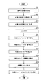
まず、高周波制御部8の周波数設定部9は、出力制御部15の割合設定部16から入力された選抜割合Wに基づいて、基本周波数を設定する(S11)。次に、高周波制御部8は、高周波源3を制御し、基本周波数の高周波K(電磁波K)を高周波空洞2に入力する(S12:高周波入力ステップ)。
次に、出力制御部15の同調部17および乱数出力部19は、周波数設定部9が設定した基本周波数に基づいて高周波空洞2にレーザ光Lを入射させるための同調タイミング(基本周波数の周期)を取得する(S13)。次に、同調部17は、同調タイミングに一致するタイミングで同調信号Uを信号出力部18に出力する。そして、同調信号Uを入力された信号出力部18は、同調タイミングでトリガ信号Gをレーザ出力部10に出力する(S14)。
次に、トリガ信号Gを入力されたレーザ出力部10は、同調タイミングでレーザ光Lを出力する(S15:レーザ出力ステップ)。次に、選抜部20は、同調タイミングに対応した乱数Rを乱数出力部19から取得する(S16)。次に、選抜部20は、取得した乱数Rに基づいて光変調部14を制御し、基本周波数の周期に対応する同調タイミングのうちの特定のタイミングのレーザ光Lのパルスを選抜する(S17:出力制御ステップ)。
次に、特定のタイミングでレーザ光Lがターゲット11に照射されることで荷電粒子が発生する(S18:粒子発生ステップ)。次に、引き出し電極12は、荷電粒子を一方向に加速することで荷電粒子ビームBを引き出し、ビーム発生装置4から荷電粒子ビームBが出力される(S19:ビーム引出ステップ)。次に、荷電粒子ビームBが高周波空洞2を通過する(S20:通過ステップ)。
(第2実施形態)
次に、第2実施形態の加速器1Aについて図4から図6を用いて説明する。なお、前述した実施形態に示される構成部分と同一構成部分については同一符号を付して重複する説明を省略する。
次に、第2実施形態の加速器1Aについて図4から図6を用いて説明する。なお、前述した実施形態に示される構成部分と同一構成部分については同一符号を付して重複する説明を省略する。
第2実施形態の加速器1Aでは、前述の第1実施形態の引き出し電極12の替わりに、出力用高周波空洞21が設けられる。なお、第2実施形態では、出力用高周波空洞21が、ビーム引出部となっている。また、第1実施形態では、光変調部14がレーザ光Lのパルスの選抜を行っているが、第2実施形態では、トリガ信号Gの出力の有無によってレーザ光Lのパルスの選抜を行う。
図4に示すように、出力用高周波空洞21は、ターゲット11に近接した位置に設けられる。また、出力用高周波空洞21の端部には、RF入力部22を介して高周波源23が接続されている。そして、出力用高周波空洞21は、ターゲット11で発生した荷電粒子を一方向に加速することで荷電粒子ビームBを引き出す。この出力用高周波空洞21で引き出された荷電粒子ビームBは、主たる高周波空洞2に入射される。
なお、出力用高周波空洞21は、出力用高周波制御部24から出力される制御信号Nにより制御される。また、出力制御部15Aの割合設定部16は、周波数情報Fを同調部17および乱数出力部19に出力するとともに、出力用高周波制御部24の周波数設定部25にも周波数情報Fを出力する。この周波数設定部25は、周波数情報Fに基づいて基本周波数を設定する。そして、出力用高周波制御部24は、設定された基本周波数に基づいて高周波源23から高周波空洞2に高周波Kを入力する。
第2実施形態の出力制御部15Aの選抜部20は、選抜信号Sを信号出力部18に入力する。また、信号出力部18は、選抜部20から出力される選抜信号Sに応じた特定のタイミングでトリガ信号Gを出力する。つまり、この選抜部20は、トリガ信号Gの出力タイミングを一定ではない間隔で選抜する。そして、基本周波数の周期に同調する一定間隔の周期である同調タイミングのうちの特定のタイミングで、レーザ光Lがレーザ出力部10から出力される。
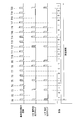
図5に示すように、高周波源3から高周波空洞2に入力される高周波Kの基本周波数の周期をT1~T20とする。ここで、出力制御部15Aの同調部17は、基本周波数の周期T1~T20に一致したタイミングで同調信号Uを信号出力部18および選抜部20に出力する。また、乱数出力部19から出力される乱数Rは、同調信号U(基本周波数の周期T1~T20)に対応して出力される。そして、この乱数Rが選抜部20に入力される。
さらに、選抜部20は、同調信号Uおよび乱数Rに応じて選抜信号Sを信号出力部18に出力する。例えば、選抜部20は、同調信号Uが入力されたときに、この同調信号Uに対応する乱数Rが「0」の場合は、トリガ信号Gを出力しない旨の選抜信号Sを信号出力部18に出力する。一方、同調信号Uに対応する乱数Rが「1」の場合は、トリガ信号Gを出力する旨の選抜信号Sを信号出力部18に出力する。なお、信号出力部18は、同調部17から入力される同調信号Uと選抜部20から入力される選抜信号Sとに応じて、トリガ信号Gを出力の有無を制御する。
なお、レーザ出力部10は、信号出力部18から出力されるトリガ信号Gに応じてレーザ光Lを出力する。そして、レーザ出力部10から出力されたレーザ光Lは、ターゲット11に照射されて荷電粒子ビームBが発生し、この荷電粒子ビームBが高周波空洞2に入射される。
すなわち、レーザ光Lの出力タイミングであって、荷電粒子ビームBの出力タイミングが乱数出力部19の乱数Rによって制御される。なお、乱数Rに応じてレーザ光Lの出力タイミングが決定されるので、高周波空洞2に入射される荷電粒子ビームBのパルス列を一定ではない間隔で選抜することができる。このようにすれば、一定ではない間隔で荷電粒子ビームBが出力されるので、高周波空洞2の内部の高次モードの発生を防ぐことができる。
このように第2実施形態では、乱数出力部19から出力される乱数Rに基づいて、信号出力部18のトリガ信号Gの出力の有無が制御されため、光変調部14などの部品を用いなくても済むようになるので、簡易的な構成で荷電粒子ビームBが出力されるタイミングを選抜することができる。
なお、第2実施形態のビーム発生装置4Aは、ターゲット11をフォトカソード部とした電子銃であっても良いし、ターゲット11をイオンターゲット部としたイオン源であっても良い。
次に、第2実施形態の加速器1Aの運転方法について図6を用いて説明する。まず、高周波制御部8の周波数設定部9は、出力制御部15Aの割合設定部16から入力された選抜割合Wに基づいて、基本周波数を設定する(S21)。次に、高周波制御部8は、高周波源3を制御し、基本周波数の高周波K(電磁波K)を高周波空洞2に入力する(S22:高周波入力ステップ)。
次に、出力制御部15Aの同調部17および乱数出力部19は、周波数設定部9が設定した基本周波数に基づいて高周波空洞2にレーザ光Lを入射させるための同調タイミング(基本周波数の周期)を取得する(S23)。次に、選抜部20は、同調タイミングに対応した乱数Rを乱数出力部19から取得する(S24)。そして、選抜部20は、同調信号Uおよび乱数Rに応じて選抜信号Sを信号出力部18に出力する。
次に、信号出力部18は、選抜部20から入力された選抜信号Sに基づいて、基本周波数の周期に対応する同調タイミングのうちの特定のタイミングのトリガ信号Gのパルスを選抜する(S25:出力制御ステップ)。次に、信号出力部18は、特定のタイミングでトリガ信号Gをレーザ出力部10に出力する(S26)。次に、トリガ信号Gを入力されたレーザ出力部10は、特定のタイミングでレーザ光Lを出力する(S27:レーザ出力ステップ)。
次に、特定のタイミングでレーザ光Lがターゲット11に照射されることで荷電粒子が発生する(S28:粒子発生ステップ)。次に、出力用高周波空洞21は、荷電粒子を一方向に加速することで荷電粒子ビームBを引き出し、ビーム発生装置4Aから荷電粒子ビームBが出力される(S29:ビーム引出ステップ)。次に、荷電粒子ビームBが高周波空洞2を通過する(S30:通過ステップ)。
本実施形態に係る加速器を第1実施形態から第2実施形態に基づいて説明したが、いずれか1の実施形態において適用された構成を他の実施形態に適用しても良いし、各実施形態において適用された構成を組み合わせても良い。例えば、第1実施形態の引き出し電極12を第2実施形態のビーム発生装置4Aに適用しても良いし、第2実施形態の出力用高周波空洞21を第1実施形態のビーム発生装置4に適用しても良い。
なお、本実施形態では、本発明が適用される加速器として線形加速器を例示しているが、本発明をサイクロトロンやシンクロトロンなどの円形加速器に適用しても良い。なお、荷電粒子は、磁場中を通るとローレンツ力を受けて軌道が曲げられる。これを利用して荷電粒子に円形の起動を描かせながら加速する加速器が円形加速器である。
本実施形態の加速器1(1A)を半導体の製造装置(半導体製造用イオン注入装置)に用いることができる。例えば、本実施形態の加速器を用いた半導体の製造方法は、前述のS20またはS30の通過ステップの後に、荷電粒子ビームBを所定の基板(半導体)に照射する照射ステップを含む。高周波空洞2を通過した荷電粒子ビームB(イオン)が基板に照射されることで、このイオンが基板に注入される。例えば、ホウ素、リンまたはヒ素などの元素をイオン化し、このイオンを加速器で加速して、シリコン、ガリウムヒ素、シリコンカーバイドまたはガラス板表面のポリシリコン薄膜などの基板に注入する。このようにすれば、半導体の電気的特性を変化させることができる。さらに、加速器を用いてイオンを照射することで、基板の深い位置までイオンを注入することができる。
本実施形態の加速器1(1A)を半導体の製造装置(半導体製造用リソグラフィ)に用いることができる。例えば、本実施形態の加速器を用いた半導体の製造方法は、前述のS20またはS30の通過ステップの後に、荷電粒子ビームB(電子)を所定のアンジュレータ(N極S極が交互に並んだ磁石列)に入射させることで、放射光発生または自由電子レーザ発振を行う光発生ステップと、発生した光によって半導体回路のリソグラフィを行うリソグラフィステップとを含む。本実施形態によって、より大電流のビームを加速することができるようになることから、高周波空洞2を通過した大電流の荷電粒子ビームB(電子)から高出力の光を発生させることができる。それによりリソグラフィを行うことで、スループットの高い回路製造が可能になる。また、アンジュレータによる光発生は、波長を自由に選ぶことが可能である。そのため、より短波長の光、例えば、13.5nmの極端紫外光を用いて行うEUV(Extreme ultraviolet lithography)リソグラフィを行うことなどができ、より微細な回路線幅を持つ半導体回路の製造が可能になる。
以上説明した実施形態によれば、基本周波数の周期に対応するタイミングのうちの特定のタイミングで荷電粒子ビームを高周波空洞に向けて出力する制御を行う出力制御部を持つことにより、高周波空洞の発熱を抑えることができる。
本発明のいくつかの実施形態を説明したが、これらの実施形態は、例として提示したものであり、発明の範囲を限定することは意図していない。これら実施形態は、その他の様々な形態で実施されることが可能であり、発明の要旨を逸脱しない範囲で、種々の省略、置き換え、変更、組み合わせを行うことができる。これら実施形態やその変形は、発明の範囲や要旨に含まれると同様に、特許請求の範囲に記載された発明とその均等の範囲に含まれるものである。
1(1A)…加速器、2…高周波空洞、3…高周波源、4(4A)…ビーム発生装置、5…主制御部、6…空洞室、7…RF入力部、8…高周波制御部、9…周波数設定部、10…レーザ出力部、11…ターゲット部、12…引き出し電極、13…直流電源、14…光変調部、15(15A)…出力制御部、16…割合設定部、17…同調部、18…信号出力部、19…乱数出力部、20…選抜部、21…出力用高周波空洞、22…RF入力部、23…高周波源、24…出力用高周波制御部、25…周波数設定部。
Claims (14)
- 荷電粒子ビームが通過可能な高周波空洞と、
基本周波数の電磁波を前記高周波空洞に入力する高周波源と、
レーザ光を出力するレーザ出力部と、
前記レーザ光が照射されることで荷電粒子を発生させるターゲット部と、
前記荷電粒子を一方向に加速することで荷電粒子ビームを引き出すビーム引出部と、
前記基本周波数の周期に対応するタイミングのうちの特定の前記タイミングで前記荷電粒子ビームを前記高周波空洞に向けて出力する制御を行う出力制御部と、
を備えることを特徴とする加速器。 - 前記出力制御部は、前記基本周波数の周期に同調する一定間隔の前記タイミングを一定ではない間隔で選抜する請求項1に記載の加速器。
- 前記出力制御部は、1の前記荷電粒子ビームが出力される前記タイミングと次の前記荷電粒子ビームが出力される前記タイミングの間隔を変更する請求項1に記載の加速器。
- 前記基本周波数の周期に対応する乱数を出力する乱数出力部を備え、
前記出力制御部は、前記乱数出力部から出力される前記乱数に基づいて前記タイミングを選抜する請求項1に記載の加速器。 - 所定期間内に前記タイミングが選抜される割合に応じて前記基本周波数を高める周波数設定部を備える請求項1に記載の加速器。
- 前記レーザ出力部が前記レーザ光を出力する契機となるトリガ信号を出力する信号出力部と、
前記トリガ信号の出力タイミングを前記基本周波数の一定間隔の周期に同調させる同調部と、
前記レーザ出力部から出力される前記レーザ光を一定ではない間隔で選抜する選抜部と、
を備える請求項1に記載の加速器。 - 前記レーザ出力部と前記ターゲット部との間に設けられて前記レーザ光を遮断可能な光変調部を備える請求項6に記載の加速器。
- 前記レーザ出力部が前記レーザ光を出力する契機となるトリガ信号を出力する信号出力部と、
前記トリガ信号の出力タイミングを前記基本周波数の一定間隔の周期に同調させる同調部と、
前記トリガ信号の出力タイミングを一定ではない間隔で選抜する選抜部と、
を備える請求項1に記載の加速器。 - 前記ビーム引出部は、前記荷電粒子を一方向に加速する電場を形成する電極である請求項1に記載の加速器。
- 前記ビーム引出部は、前記荷電粒子を一方向に加速する電場を形成する出力用高周波空洞である請求項1に記載の加速器。
- 前記ターゲット部がカソード部であり、このカソード部に前記レーザ光が照射されることで生じる光電効果によって、前記荷電粒子としての電子が発生する請求項1に記載の加速器。
- 前記ターゲット部がイオンターゲット部であり、このイオンターゲット部に前記レーザ光が照射されることで生じるアブレーションプラズマによって、前記荷電粒子としてのイオンが発生する請求項1に記載の加速器。
- 基本周波数の電磁波を高周波源から高周波空洞に入力する高周波入力ステップと、
レーザ出力部からレーザ光を出力するレーザ出力ステップと、
前記レーザ光がターゲット部に照射されることで荷電粒子を発生させる粒子発生ステップと、
前記荷電粒子を一方向に加速することで荷電粒子ビームを引き出すビーム引出ステップと、
前記基本周波数の周期に対応するタイミングのうちの特定の前記タイミングで前記荷電粒子ビームを前記高周波空洞に向けて出力する制御を行う出力制御ステップと、
前記荷電粒子ビームが前記高周波空洞を通過する通過ステップと、
を含むことを特徴とする加速器の運転方法。 - 基本周波数の電磁波を高周波源から高周波空洞に入力する高周波入力ステップと、
レーザ出力部からレーザ光を出力するレーザ出力ステップと、
前記レーザ光がターゲット部に照射されることで荷電粒子を発生させる粒子発生ステップと、
前記荷電粒子を一方向に加速することで荷電粒子ビームを引き出すビーム引出ステップと、
前記基本周波数の周期に対応するタイミングのうちの特定の前記タイミングで前記荷電粒子ビームを前記高周波空洞に向けて出力する制御を行う出力制御ステップと、
前記荷電粒子ビームが前記高周波空洞を通過する通過ステップと、
前記高周波空洞を通過した前記荷電粒子ビームをアンジュレータに入射させて光を発生させる光発生ステップと、
発生した前記光を用いて電子回路のリソグラフィを行うリソグラフィステップと、
を含むことを特徴とする加速器を用いた半導体の製造方法。
Priority Applications (1)
| Application Number | Priority Date | Filing Date | Title |
|---|---|---|---|
| JP2018537437A JP6649495B2 (ja) | 2016-09-02 | 2017-09-01 | 加速器、加速器の運転方法および加速器を用いた半導体の製造方法 |
Applications Claiming Priority (2)
| Application Number | Priority Date | Filing Date | Title |
|---|---|---|---|
| JP2016171452 | 2016-09-02 | ||
| JP2016-171452 | 2016-09-02 |
Publications (1)
| Publication Number | Publication Date |
|---|---|
| WO2018043709A1 true WO2018043709A1 (ja) | 2018-03-08 |
Family
ID=61301053
Family Applications (1)
| Application Number | Title | Priority Date | Filing Date |
|---|---|---|---|
| PCT/JP2017/031582 Ceased WO2018043709A1 (ja) | 2016-09-02 | 2017-09-01 | 加速器、加速器の運転方法および加速器を用いた半導体の製造方法 |
Country Status (3)
| Country | Link |
|---|---|
| JP (1) | JP6649495B2 (ja) |
| TW (1) | TW201826648A (ja) |
| WO (1) | WO2018043709A1 (ja) |
Cited By (3)
| Publication number | Priority date | Publication date | Assignee | Title |
|---|---|---|---|---|
| WO2019206967A1 (en) | 2018-04-25 | 2019-10-31 | Adam S.A. | A variable-energy proton linear accelerator system and a method of operating a proton beam suitable for irradiating tissue |
| JP2021018989A (ja) * | 2019-07-16 | 2021-02-15 | 清華大学Tsinghua University | マルチ線源加速器及び検査方法 |
| US11406847B2 (en) | 2018-04-25 | 2022-08-09 | Adam S.A. | Proton linear accelerator system for irradiating tissue with two or more RF sources |
Citations (6)
| Publication number | Priority date | Publication date | Assignee | Title |
|---|---|---|---|---|
| JPH0676990A (ja) * | 1992-08-25 | 1994-03-18 | Hamamatsu Photonics Kk | 光制御加速器システム |
| JPH11176595A (ja) * | 1997-12-08 | 1999-07-02 | Mitsubishi Heavy Ind Ltd | 電子加速装置 |
| JP2005228489A (ja) * | 2004-02-10 | 2005-08-25 | Japan Atom Energy Res Inst | 大強度狭帯域の軌道放射光を同時に複数のビームラインで利用可能にする方法 |
| JP2008243375A (ja) * | 2007-03-23 | 2008-10-09 | Ihi Corp | 荷電粒子ビーム減速装置および方法とこれを用いたx線発生装置 |
| WO2012043475A1 (ja) * | 2010-09-27 | 2012-04-05 | 大学共同利用機関法人高エネルギー加速器研究機構 | 光陰極高周波電子銃空洞装置 |
| JP2014164855A (ja) * | 2013-02-22 | 2014-09-08 | Toshiba Corp | イオン加速装置及び医療用装置 |
Family Cites Families (2)
| Publication number | Priority date | Publication date | Assignee | Title |
|---|---|---|---|---|
| JP5294293B2 (ja) * | 2006-07-10 | 2013-09-18 | 株式会社 エックスネット | 電子線照射装置 |
| JP5409428B2 (ja) * | 2009-03-31 | 2014-02-05 | 株式会社日立製作所 | 荷電粒子照射システム及び照射計画装置 |
-
2017
- 2017-09-01 WO PCT/JP2017/031582 patent/WO2018043709A1/ja not_active Ceased
- 2017-09-01 TW TW106129892A patent/TW201826648A/zh unknown
- 2017-09-01 JP JP2018537437A patent/JP6649495B2/ja active Active
Patent Citations (6)
| Publication number | Priority date | Publication date | Assignee | Title |
|---|---|---|---|---|
| JPH0676990A (ja) * | 1992-08-25 | 1994-03-18 | Hamamatsu Photonics Kk | 光制御加速器システム |
| JPH11176595A (ja) * | 1997-12-08 | 1999-07-02 | Mitsubishi Heavy Ind Ltd | 電子加速装置 |
| JP2005228489A (ja) * | 2004-02-10 | 2005-08-25 | Japan Atom Energy Res Inst | 大強度狭帯域の軌道放射光を同時に複数のビームラインで利用可能にする方法 |
| JP2008243375A (ja) * | 2007-03-23 | 2008-10-09 | Ihi Corp | 荷電粒子ビーム減速装置および方法とこれを用いたx線発生装置 |
| WO2012043475A1 (ja) * | 2010-09-27 | 2012-04-05 | 大学共同利用機関法人高エネルギー加速器研究機構 | 光陰極高周波電子銃空洞装置 |
| JP2014164855A (ja) * | 2013-02-22 | 2014-09-08 | Toshiba Corp | イオン加速装置及び医療用装置 |
Cited By (6)
| Publication number | Priority date | Publication date | Assignee | Title |
|---|---|---|---|---|
| WO2019206967A1 (en) | 2018-04-25 | 2019-10-31 | Adam S.A. | A variable-energy proton linear accelerator system and a method of operating a proton beam suitable for irradiating tissue |
| CN110393864A (zh) * | 2018-04-25 | 2019-11-01 | 先进肿瘤治疗公开有限公司 | 可变能量质子直线加速器系统和质子束的操作方法 |
| US20210243878A1 (en) * | 2018-04-25 | 2021-08-05 | Adam S.A. | A variable-energy proton linear accelerator system and a method of operating a proton beam suitable for irradiating tissue |
| US11406847B2 (en) | 2018-04-25 | 2022-08-09 | Adam S.A. | Proton linear accelerator system for irradiating tissue with two or more RF sources |
| JP2021018989A (ja) * | 2019-07-16 | 2021-02-15 | 清華大学Tsinghua University | マルチ線源加速器及び検査方法 |
| JP7038167B2 (ja) | 2019-07-16 | 2022-03-17 | 清華大学 | マルチ線源加速器及び検査方法 |
Also Published As
| Publication number | Publication date |
|---|---|
| JPWO2018043709A1 (ja) | 2019-06-24 |
| JP6649495B2 (ja) | 2020-02-19 |
| TW201826648A (zh) | 2018-07-16 |
Similar Documents
| Publication | Publication Date | Title |
|---|---|---|
| Bacal et al. | Negative hydrogen ion production mechanisms | |
| US9053833B2 (en) | DC high-voltage super-radiant free-electron based EUV source | |
| EP2452545B1 (en) | Interleaving multi-energy x-ray energy operation of a standing wave linear accelerator using electronic switches | |
| TWI673575B (zh) | 輻射源 | |
| JP6649495B2 (ja) | 加速器、加速器の運転方法および加速器を用いた半導体の製造方法 | |
| CN109712858B (zh) | 激光微波离子源 | |
| KR20020003802A (ko) | 광자 발생기 | |
| WO2020166116A1 (ja) | イオン源、およびこれを用いた円形加速器ならびに粒子線治療システム | |
| Semenov et al. | Reduction of the multipactor threshold due to electron cyclotron resonance | |
| Neculaes et al. | Low-noise microwave oven magnetrons with fast start-oscillation by azimuthally varying axial magnetic fields | |
| RU2010127452A (ru) | Способ генерации тормозного излучения с поимпульсным переключением энергии и источник излучения для его осуществления | |
| Chen | Excitation of large amplitude plasma waves | |
| Liu et al. | Design of a C-Band High-Efficiency Multi-Beam Klystron | |
| Ronald et al. | Auroral magnetospheric cyclotron emission processes: numerical and experimental simulations | |
| JP4756283B2 (ja) | 電子ビーム発生装置、x線発生装置及びx線利用装置 | |
| Kumar et al. | On the design of a high-efficiency double-beam gyrotron | |
| Denisov | New developments in Russia of gyrotrons for plasma fusion installations | |
| RU2760284C1 (ru) | Источник рентгеновского излучения с циклотронным авторезонансом | |
| Vikharev et al. | Multipactor discharge in crossed fields in a cylindrical cavity for the 3-cm wavelength band | |
| DK2339899T3 (en) | Compact source of generation of charged particles | |
| Loza et al. | Increase in the average radiation power of a plasma relativistic microwave generator | |
| KR200267714Y1 (ko) | 초고주파 발생 장치 | |
| Wright et al. | Design and construction of a table top microwave free electron maser for industrial applications | |
| RU2625458C1 (ru) | Релятивистский СВЧ-генератор | |
| JP2001052896A (ja) | 粒子加速・蓄積装置 |
Legal Events
| Date | Code | Title | Description |
|---|---|---|---|
| 121 | Ep: the epo has been informed by wipo that ep was designated in this application |
Ref document number: 17846712 Country of ref document: EP Kind code of ref document: A1 |
|
| ENP | Entry into the national phase |
Ref document number: 2018537437 Country of ref document: JP Kind code of ref document: A |
|
| NENP | Non-entry into the national phase |
Ref country code: DE |
|
| 122 | Ep: pct application non-entry in european phase |
Ref document number: 17846712 Country of ref document: EP Kind code of ref document: A1 |