WO2018043656A1 - 光照射装置 - Google Patents
光照射装置 Download PDFInfo
- Publication number
- WO2018043656A1 WO2018043656A1 PCT/JP2017/031411 JP2017031411W WO2018043656A1 WO 2018043656 A1 WO2018043656 A1 WO 2018043656A1 JP 2017031411 W JP2017031411 W JP 2017031411W WO 2018043656 A1 WO2018043656 A1 WO 2018043656A1
- Authority
- WO
- WIPO (PCT)
- Prior art keywords
- light
- reflecting portion
- wire
- reflecting
- center
- Prior art date
- Legal status (The legal status is an assumption and is not a legal conclusion. Google has not performed a legal analysis and makes no representation as to the accuracy of the status listed.)
- Ceased
Links
Images





Classifications
-
- C—CHEMISTRY; METALLURGY
- C03—GLASS; MINERAL OR SLAG WOOL
- C03C—CHEMICAL COMPOSITION OF GLASSES, GLAZES OR VITREOUS ENAMELS; SURFACE TREATMENT OF GLASS; SURFACE TREATMENT OF FIBRES OR FILAMENTS MADE FROM GLASS, MINERALS OR SLAGS; JOINING GLASS TO GLASS OR OTHER MATERIALS
- C03C25/00—Surface treatment of fibres or filaments made from glass, minerals or slags
- C03C25/10—Coating
- C03C25/104—Coating to obtain optical fibres
- C03C25/106—Single coatings
-
- C—CHEMISTRY; METALLURGY
- C03—GLASS; MINERAL OR SLAG WOOL
- C03C—CHEMICAL COMPOSITION OF GLASSES, GLAZES OR VITREOUS ENAMELS; SURFACE TREATMENT OF GLASS; SURFACE TREATMENT OF FIBRES OR FILAMENTS MADE FROM GLASS, MINERALS OR SLAGS; JOINING GLASS TO GLASS OR OTHER MATERIALS
- C03C25/00—Surface treatment of fibres or filaments made from glass, minerals or slags
- C03C25/10—Coating
- C03C25/12—General methods of coating; Devices therefor
-
- F—MECHANICAL ENGINEERING; LIGHTING; HEATING; WEAPONS; BLASTING
- F21—LIGHTING
- F21V—FUNCTIONAL FEATURES OR DETAILS OF LIGHTING DEVICES OR SYSTEMS THEREOF; STRUCTURAL COMBINATIONS OF LIGHTING DEVICES WITH OTHER ARTICLES, NOT OTHERWISE PROVIDED FOR
- F21V7/00—Reflectors for light sources
- F21V7/04—Optical design
- F21V7/09—Optical design with a combination of different curvatures
Definitions
- This invention relates to the light irradiation apparatus which irradiates light toward a wire.
- a light irradiation device including a curved reflection portion and a light emitting portion that emits light is known (for example, Patent Document 1). And a wire is inserted in the inside of a reflection part, and the light emission part is light-emitting toward the wire from the circumferential direction of a wire.
- the light efficiency of the light irradiation apparatus according to Patent Document 1 is low.
- light that has traveled between the end portion of the reflecting portion and the end portion of the light emitting portion does not irradiate the wire, which is one of the main factors that reduce the light efficiency.
- light efficiency means the ratio of the light which irradiated the wire actually among the light light-emitted from the light emission part.
- the problem is to provide a light irradiation device capable of improving the light efficiency.
- the light irradiation device is disposed on a concave inner surface formed in an arc shape, and includes a first reflecting portion into which a wire is inserted, and at least one light emitting portion that emits light from the circumferential direction of the wire toward the wire.
- a second reflection part formed in a planar shape, and at least a part of the second reflection part is formed between the end of the first reflection part and the light emitting part in the circumferential direction of the first reflection part. It arrange
- the second reflecting portion may be arranged so that an angle of intersection with the radial direction of the first reflecting portion is larger than 0 ° and smaller than 90 °.
- the light irradiation device includes an insertion portion that forms an insertion path for inserting the wire into the first reflection portion, and the first reflection portion is centered on the insertion path. It may be arranged so as to be eccentric with respect to the center.
- the light irradiation device has an excellent effect that the light efficiency can be improved.
- FIG. 4 is an enlarged sectional view taken along line IV-IV in FIG. 2.
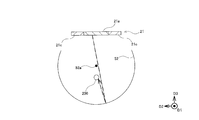
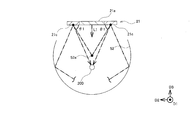
- FIG. 5 is an enlarged view of a V region in FIG. 4. It is principal part sectional drawing of the light irradiation apparatus which concerns on an Example, Comprising: It is a figure explaining the irradiation state of the light to a wire.
- the light irradiation apparatus 1 As shown in FIG. 1, the light irradiation apparatus 1 according to this embodiment is used in an optical fiber manufacturing apparatus 100 that manufactures an optical fiber 200 that is a wire 200. Therefore, prior to describing each configuration of the light irradiation apparatus 1, the optical fiber manufacturing apparatus 100 will be described.
- the optical fiber manufacturing apparatus 100 includes a transport apparatus 110 that transports the optical fiber 200 along a transport direction (downward in FIG. 1) D1, and a coating apparatus 120 that applies an ultraviolet curable resin to the transported optical fiber 200. It has.
- the transport device 110 then transports the transport members 111 and 112 that transport the optical fiber 200 while holding the optical fiber 200 so that the optical fiber 200 is inserted into a predetermined position inside the light irradiation device 1. And on the downstream side.
- the light irradiation apparatus 1 hardens the resin applied to the optical fiber 200 by, for example, irradiating the optical fiber 200 traveling inside at a speed of 1000 meters per minute with ultraviolet rays.
- the optical fiber 200 manufactured by the optical fiber manufacturing apparatus 100 is composed of, for example, a bare optical fiber made of glass fiber and a coating film in which an ultraviolet curable resin is cured.
- the light irradiation apparatus 1 includes a light source unit 2 that irradiates light toward an optical fiber (wire) 200, an insertion unit 3 into which the optical fiber 200 is inserted, It has. Moreover, the light irradiation apparatus 1 is provided with the connection part 4 which connects the light source unit 2 and the insertion unit 3 rotatably with the rotating shaft 4a.
- the light source unit 2 includes a light source 21 that emits light toward the optical fiber 200, a light source cooling unit 22 that cools the light source 21, and a housing 23 that houses the light source 21 and the like.
- the light source unit 2 also includes a power supply unit 24 for supplying power to the light source 21.
- the light source 21 is formed in a long shape along the extending direction (conveying direction) D1 of the optical fiber 200.
- the light source 21 is arranged so as to face the optical fiber 200.
- the light source 21 emits ultraviolet light (for example, light having a wavelength of 300 nm to 400 nm) in order to cure the ultraviolet curable resin.
- the light source cooling unit 22 is connected to the light source 21 and has a cooling main body 22a through which the cooling water flows, an inflow portion 22b for flowing the cooling water into the cooling main body 22a, and an outflow of the cooling water from the cooling main body 22a.
- the outflow part 22c is provided.
- the cooling body 22 a is disposed inside the housing 23, and the inflow portion 22 b and the outflow portion 22 c are disposed outside the housing 23.
- the housing 23 includes a light-transmitting portion 23a that transmits light emitted from the light source 21 and a light-shielding portion 23b that blocks light.
- the translucent portion 23a is formed in a long shape along the direction (transport direction) D1 in which the optical fiber 200 extends. And the translucent part 23a is arrange
- the power supply unit 24 is connected to a power supply connection unit 24a to which a cable or the like is connected, and various types of electrical connection between the power supply connection unit 24a and the light source 21 are performed. And a terminal block 24b having terminals.
- the power connection 24 a is disposed outside the housing 23, and the terminal block 24 b is disposed inside the housing 23.
- the insertion unit 3 includes a main body portion 5 into which the optical fiber 200 is inserted, an insertion portion 6 that forms an insertion path 61 for inserting the optical fiber 200 into the main body portion 5, and an insertion portion 6. And a fixing part 7 for fixing the main body part 5 to the main body part 5. Further, the insertion unit 3 includes a main body cooling unit 8 that cools the main body unit 5.
- the fixing part 7 includes a pair of clamping parts 71 and 72 that clamp the insertion part 6. And the fixing
- the main body cooling section 8 is connected to the main body section 5 and the cooling main body 8a through which the cooling water flows, the inflow section 8b for flowing the cooling water into the cooling main body 8a, and the cooling water from the cooling main body 8a. And an outflow portion 8c.
- the main body cooling unit 8 (cooling main body 8 a) is configured to be detachable from the main body unit 5.
- the main body 5 is formed in a long shape along the extending direction (conveying direction) D ⁇ b> 1 of the optical fiber 200.
- the main-body part 5 is equipped with the recessed part 51 in which the optical fiber 200 is inserted inside along a longitudinal direction.
- the recessed part 51 is equipped with the 1st reflection part 52 which reflects light in the inner surface formed in circular arc shape.
- the concave portion 51 includes one opening 53 on one side in the circumferential direction of the first reflecting portion 52.
- the first reflecting portion 52 is formed in a long shape along the direction (transport direction) D1 in which the optical fiber 200 extends. And the 1st reflection part 52 is formed in the curved surface. Specifically, the first reflecting portion 52 is formed in an arc shape composed of a part of a true circle in a cross section by a plane orthogonal to the longitudinal direction. And the 1st reflection part 52 is formed in the magnitude
- the opening 53 is formed in a long shape along the direction (transport direction) D1 in which the optical fiber 200 extends. And the opening part 53 is covered with the translucent part 23a, and is arrange
- the insertion portion 6 includes an insertion hole 62 that forms an insertion path 61 therein, and the insertion hole 62 is disposed inside and outside the first reflection portion 52.
- the insertion portion 6 is formed of a cylindrical body having translucency and is formed along the direction (transport direction) D1 in which the optical fiber 200 extends so that the insertion hole 62 is The first reflective portion 52 is disposed inside and outside.
- the insertion hole 62 is formed in the circular shape in the cross section by the orthogonal surface with respect to a longitudinal direction. That is, the insertion hole 62 forms a circular insertion path 61 therein.
- the insertion portion 6 is a quartz tube, and the insertion portion 6 is filled with nitrogen. Thereby, it can suppress that the polymerization reaction at the time of hardening
- the first reflecting portion 52 is arranged so that the arc-shaped center 52 a is eccentric with respect to the center 61 a of the insertion path 61.
- the insertion portion 6 (insertion hole 62) is disposed such that the center 61a of the insertion path 61 is eccentric with respect to the arc-shaped center 52a of the first reflection portion 52.
- the first reflecting portion 52 is arranged such that the center 52a is decentered with respect to the center 61a of the insertion path 61 in the optical axis direction L1 of the emitted light from the light source 21 (the direction in which it is in contact with and away from the light source 21). Yes.
- the insertion portion 6 (insertion hole 62) is disposed such that the center 61a of the insertion path 61 is decentered in the optical axis direction L1 with respect to the arc-shaped center 52a of the first reflection portion 52.
- the first reflecting portion 52 is arranged so that the center 52a is eccentric in the direction closer to the light source 21 than the center 61a of the insertion path 61.
- the insertion portion 6 (insertion hole 62) is arranged such that the center 61a of the insertion path 61 is eccentric in the direction away from the light source 21 with respect to the center 52a of the first reflection portion 52.
- the arrangement of the light source 21 and the first reflecting portion 52 is line symmetric with respect to the base axis extending in the optical axis direction L1.
- the arc-shaped center 52 a of the first reflecting portion 52 is the center of an inscribed circle that is inscribed in the first reflecting portion 52.
- the center 61a of the insertion path 61 is the center of an inscribed circle that is inscribed in a surface (in the present embodiment, the inner surface of the insertion hole 62) that constitutes the insertion path 61.
- the light source 21 is a reflector 21d having a light emitting portion 21a that emits light from the circumferential direction of the optical fiber 200 toward the optical fiber 200, a substrate 21b that supports the light emitting portion 21a, and a second reflecting portion 21c that is formed in a planar shape. And. And the light emission part 21a, the board
- the light emitting unit 21a is a solid light source element (for example, LED) in the present embodiment.
- the light emitting unit 21a is not limited to such a configuration, and may be any member that emits light toward the optical fiber 200.
- the light emitting unit 21a is fixed to one surface of the substrate 21b, and the other surface of the substrate 21b is fixed to the light source cooling unit 22 (specifically, the cooling main body 22a).
- the reflector 21d is fixed to one surface of the substrate 21b.
- the reflector 21 may be formed by applying a coating material made of a reflective material on one surface of the substrate 21b, and the mirror is fixed to the one surface of the substrate 21b with an adhesive, a bolt, or the like. May be.
- a pair of reflectors 21d are provided so as to sandwich the light emitting portion 21a.
- a pair of second reflecting portions 21c are provided so as to sandwich the light emitting portion 21a.
- the second reflecting portion 21c is arranged so as to face the center 52a of the first reflecting portion 52. Specifically, the second reflecting portion 21c is arranged so as to be orthogonal to the optical axis direction L1 of the emitted light from the light source 21. The entire second reflecting portion 21 c is disposed between the end portion 52 b of the first reflecting portion 52 and the end portion 21 e of the light emitting portion 21 a in the circumferential direction of the first reflecting portion 52.
- the second reflecting portion 21c is disposed closer to the light source 21 than the center 52a of the first reflecting portion 52 in the optical axis direction L1 of the emitted light from the light source 21.
- the second reflecting portion 21 c reflects a part of the incident light without irradiating the optical fiber 200 toward the optical fiber 200.
- the second reflecting portion 21c When the light from the light emitting portion 21a is incident, the second reflecting portion 21c reflects the light by 50% or more, preferably 60% or more, more preferably 70% or more, and further preferably 80% or more. It is configured to do so. Moreover, the 2nd reflection part 21c may be comprised so that the incident light may be specularly reflected, and may be comprised so that it may be diffusely reflected.
- the positions of the light emitting part 21 a and the first reflecting part 52 are different, but the positions of the light emitting part 21 a and the wire 200 are the same. . Therefore, the amount of light that is emitted from the light emitting unit 21a and directly irradiates the wire 200 without being reflected by the first reflecting unit 52 is the same.
- the center of the wire 200 coincides with the arc-shaped center 52 a of the first reflecting portion 52.
- the light of the first reflecting portion 52 has a circular shape. After passing through the vicinity of the arc-shaped center 52a, it is necessary to reflect by the first reflecting portion 52 (see the broken line in FIG. 6).
- the center of the wire 200 is decentered with respect to the arc-shaped center 52 a of the first reflecting portion 52.
- light does not need to pass through the position of the wire 200 in order to irradiate the back side of the wire 200. Therefore, a part of the light emitted from the light emitting unit 21 a and reflected by the first reflecting unit 52 irradiates the back side of the wire 200. Thereby, the back side of the wire 200 is irradiated with light similarly to the front side of the wire 200.
- the amount of light emitted from the light emitting portion 21a and directly irradiating the wire 200 is the same, but is emitted from the light emitting portion 21a and is the first.
- the amount of light that irradiates the wire 200 after being reflected by the reflector 52 is different.
- a configuration in which the center of the wire 200 is eccentric with respect to the arc-shaped center 52a of the first reflecting portion 52 is preferable. That is, a configuration in which the center 61 a of the insertion path 61 is eccentric with respect to the arc-shaped center 52 a of the first reflecting portion 52 is preferable.
- the first reflecting portion 52 is formed in an arc shape. For this reason, the optical path of the light emitted from the light source 21 (light emitting unit 21a) is easily reflected back by the first reflecting unit 52 and easily returned to the light source 21 side again. Moreover, since the diameter of the wire 200 which is an irradiation object may be comparatively small, most of the light emitted from the light source 21 is repeatedly reflected by the first reflection unit 52 or absorbed by the light source 21. The light efficiency is not good.
- the second reflecting portion 21c is provided between the end portion 21e of the light emitting portion 21a and the end portion 52b of the first reflecting portion 52, so that the optical path of the light returning to the light source 21 side is directed to the wire 200 side. be able to. Thereby, light efficiency can be improved.
- the radial direction of the second reflector 9a and the first reflector 52 of one reflector 9 (specifically, from the center 52a of the first reflector 52 to the second reflector 9a).
- the crossing angle ⁇ 1 between the second reflecting portion 10a of the other reflector 10 and the radial direction of the first reflecting portion 52 is 90 °. °.
- the crossing angle ⁇ 1 between the second reflecting portion 21c and the radial direction of the first reflecting portion 52 is larger than 0 ° and smaller than 90 ° (in FIG. 9, It is about 60 °).
- the radial direction of the first reflecting portion 52 serving as a reference for the intersection angle ⁇ 1 is the radial direction of the first reflecting portion 52 that passes through the centers of the second reflecting portions 9a, 10a, and 21c. Further, when the first reflector 52 is disposed so as to face the first reflector 52 and along the radial direction of the first reflector 52 like the second reflector 9a of one reflector 9, the intersection angle ⁇ 1 is 0. °.
- the direction in which the second reflecting portions 52, 9a, 10a, and 21c rotate from the position where the intersecting angle ⁇ 1 is 0 ° so as to face the center 52a of the first reflecting portion 52 is the direction in which the intersecting angle ⁇ 1 increases. is there.
- the clockwise direction is a direction in which the crossing angle ⁇ 1 increases
- the counterclockwise direction is increased.
- the direction is the direction in which the crossing angle ⁇ 1 increases.
- the crossing angle ⁇ 1 of the second reflecting portion 9a is 90 ° to about 180 °
- the light traveling around the wire 200 is reflected by the second reflecting portion 9a
- most of the light is It progresses away from the center 52a of the first reflecting part 52.
- the crossing angle ⁇ 1 of the second reflecting portion 9a is about 180 ° to about 270 °, the light traveling around the wire 200 is difficult to be incident on the second reflecting portion 9a.
- the crossing angle ⁇ 1 of the second reflecting portion 21c is larger than 0 ° and smaller than 90 °, a part of the light after the light traveling around the wire 200 is reflected by the second reflecting portion 21c Will irradiate the wire 200.
- the intersection angle ⁇ 1 of the second reflecting portion 21c is larger than 0 ° and smaller than 90 °, the light efficiency can be improved efficiently.
- the crossing angle ⁇ 1 of the second reflecting portion 21c is larger than 0 ° and smaller than 90 °.
- the intersection angle ⁇ 1 of the second reflecting portion 21c is not limited to such a configuration.
- the angle at which the second reflecting portion 21 intersects with the direction orthogonal to the optical axis direction L1 of the light emitted from the light source 21 is 30 ° or less. In the embodiment according to FIG. 9, the angle is 0 °.
- the wire 200 is irradiated with direct irradiation light from the light emitting unit 21a, reflected light from the first reflecting unit 52, and reflected light from the second reflecting unit 21c. That is, the light source 21 can substantially widen the light emitting area by combining the light emitting part 21a and the second reflecting part 21c. Thereby, since light can be emitted in a relatively wide area, even if the position of the wire rod 200 is shifted due to the vibration of the wire rod 200, variation in the amount of light applied to the wire rod 200 can be suppressed. As a result, high light efficiency can be maintained.
- the light quantity of the direct irradiation light from the light emission part 21a becomes the maximum by arrange
- the light irradiation device 1 is disposed on the concave inner surface formed in an arc shape, and the first reflecting portion 52 into which the wire 200 is inserted, and the circumferential direction of the wire 200 And at least one (in the present embodiment, one) light emitting portion 21a that emits light toward the wire 200, and a second reflecting portion 21c formed in a planar shape, and at least the second reflecting portion 21c.
- a part (the whole in the present embodiment) is disposed between the end 52b of the first reflecting part 52 and the end 21e of the light emitting part 21a in the circumferential direction of the first reflecting part 52. .
- the first reflecting portion 52 is disposed on the concave inner surface formed in an arc shape.
- the wire rod 200 is inserted into the first reflecting portion 52, and at least one (in this embodiment, one) light emitting portion 21a emits light from the circumferential direction of the wire rod 200 toward the wire rod 200. Yes.
- the second reflecting portion 21c is formed in a planar shape.
- at least a part (the whole in the present embodiment) of the second reflecting portion 21c is, in the circumferential direction of the first reflecting portion 52, an end portion 52b of the first reflecting portion 52 and an end portion 21e of the light emitting portion 21a. It is arranged between.
- the second reflecting portion 21c is configured such that the intersection angle ⁇ 1 with the radial direction of the first reflecting portion 52 is larger than 0 ° and smaller than 90 °. It is the composition of being arranged.
- the intersection angle ⁇ 1 between the second reflecting portion 21c and the radial direction of the first reflecting portion 52 is larger than 0 ° and smaller than 90 °.
- the light irradiation device 1 includes the insertion portion 6 that forms therein an insertion path 61 for inserting the wire 200 into the first reflecting portion 52, and includes the first The reflecting part 52 is configured such that the center 52a is arranged to be eccentric with respect to the center 61a of the insertion path 61.
- the insertion portion 6 forms the insertion path 61 for inserting the wire 200 into the first reflection portion 52 inside.
- the center 52a of the 1st reflection part 52 is eccentric with respect to the center 61a of the insertion path 61, the wire 200 is located off the center 52a of the 1st reflection part 52. Therefore, a part of the light emitted from the light emitting unit 21 a and reflected by the first reflecting unit 52 travels toward the wire 200 and irradiates the wire 200. Therefore, the light efficiency can be improved efficiently.
- the light irradiation device is not limited to the configuration of the above-described embodiment, and is not limited to the above-described effects.
- the light irradiation device can be variously modified without departing from the gist of the present invention. For example, it is needless to say that one or a plurality of configurations and methods according to various modifications described below may be arbitrarily selected and employed in the configurations and methods according to the above-described embodiments.
- the entire second reflecting portion 21c is formed between the end portion 52b of the first reflecting portion 52 and the end portion 21e of the light emitting portion 21a in the circumferential direction of the first reflecting portion 52. It is the structure of being arrange
- the light irradiation device is not limited to such a configuration.
- a part of the second reflecting portion 23 c is between the end portion 52 b of the first reflecting portion 52 and the end portion 21 e of the light emitting portion 21 a in the circumferential direction of the first reflecting portion 52.
- the structure of being arranged may be sufficient.
- the light irradiation apparatus 1 which concerns on the said embodiment, it is the structure that the member 5 which has the 1st reflection part 52 differs from the member 2 which has the 2nd reflection part 21c.
- the light irradiation device is not limited to such a configuration.
- the member 5 having the first reflecting portion 52 and the member 5 having the second reflecting portion 54 a may be the same. That is, the structure that the 1st reflection part 52 and the 2nd reflection part 54a are integrally formed may be sufficient.
- the light irradiation device is not limited to such a configuration.
- the second reflecting portion 23 c may be provided on the reflector 23 d included in the housing 23.
- the second reflecting portion 23 c may be configured to include the second reflecting portion 23 c.
- the structure that the part 54a is provided in the convex-shaped reflector 54 which the main-body part 5 has may be sufficient.
- the reflector 21d having the second reflecting portion 21c is fixed to the substrate 21b.
- the light irradiation device is not limited to such a configuration.
- the reflector 21d having the second reflecting portion 21c may be fixed to the light source cooling portion 22 (specifically, the cooling main body 22a).
- the reflector 21 d having the second reflecting portion 21 c may be fixed to a holding body 21 f that holds the substrate 21 b on the light source cooling portion 22.
- the first reflecting part 52 is configured to be formed in an arc shape including a part of a true circle.
- the light irradiation device is not limited to such a configuration.
- the first reflecting portion 52 may be formed in an arc shape formed of a part of an ellipse.
- the first reflecting portion 52 may be configured such that a plurality of planes are formed in an arc shape, that is, formed in a polygonal shape.
- the 1st reflection part 52 should just be formed in the magnitude
- the first reflecting portion 52 may be formed not only in a circular arc shape that is a part of a circular shape, but also in a circular arc shape that is the entire circular shape (that is, a circular shape). .
- the “arc shape” in the “first reflecting portion arranged on the concave inner surface formed in an arc shape” is between two circles (the first circle C1 and the second circle C2) having the same center C0 position.
- the relationship between the diameter of the first circle C1 and the diameter of the second circle C2 ( ⁇ diameter of the first circle C1) satisfies the following formula. 100% ⁇ (diameter of second circle C2) / (diameter of first circle C1) ⁇ 110%
- the following formula may be satisfied. 100% ⁇ (diameter of second circle C2) / (diameter of first circle C1) ⁇ 105%
- the position of the arc-shaped center 52a of the first reflecting portion 52 is such that “(the diameter of the second circle C2) / (the diameter of the first circle C1)” is the minimum. This is the position of the center C0.
- the 1st reflection part 52 may be the shape which consists of a part of the ellipse which enters between the 1st circle C1 and the 2nd circle C2.
- the insertion hole 62 is formed in a circular shape.
- the light irradiation device is not limited to such a configuration.
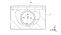
- the insertion hole 62 may be configured to have an elliptical shape, or the insertion hole 62 may be formed to have a polygonal shape as illustrated in FIG. 16, for example.
- the center 61a of the insertion path 61 is the center of an inscribed circle (circle C3 in FIG. 16) that is inscribed in the surface constituting the insertion path 61.
- the insertion path 61 is configured by an insertion hole 62 that is a configuration different from the first reflection unit 52.
- the light irradiation device is not limited to such a configuration.
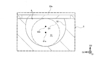
- the light irradiation apparatus does not include such an insertion hole 62, and as shown in FIG. 17, the first reflecting portion 52 constitutes at least a part of the insertion portion 6, and the center 52a is the insertion path.
- the structure of being formed so that it may be eccentric with respect to the center 61a of 61 may be sufficient.
- the insertion path 61 is comprised by the internal space comprised by the 1st reflection part 52 and the translucent part 23a. Note that the center 61a of the insertion path 61 is the center of an inscribed circle C4 that is inscribed in the surface (the surfaces of the first reflection part 52 and the light transmission part 23a in FIG. 17) that constitute the insertion path 61.
- the insertion portion 6 is formed in a long cylindrical shape and is disposed inside and outside the first reflection portion 52, so that the insertion hole 62 has the first shape. It is the structure that it is arrange
- the light irradiation device is not limited to such a configuration.
- the configuration may be such that the insertion hole 62 is disposed only inside the first reflecting portion 52.
- the insertion hole 62 is disposed only in a peripheral portion where the insertion portion 6 is fixed to the fixing portion 7.
- the insertion hole 62 may be configured to be disposed only outside the first reflecting portion 52.
- the light irradiation apparatus 1 which concerns on the said embodiment, it is the structure that one light emission part 21a (light source 21) is provided.
- the light irradiation device is not limited to such a configuration.
- the structure that the light emission part 21a (light source 21) is provided with two or more may be sufficient.
- the first reflecting portion 52 is configured so that the center 52a is eccentric with respect to the center 61a of the insertion path 61.
- the light irradiation device is not limited to such a configuration.
- the first reflecting portion 52 may be arranged such that the center 52a coincides with the center 61a of the insertion path 61.
- the structure that the wire 200 is an optical fiber.
- the light irradiation device is not limited to such a configuration.
- the structure that the wire 200 is a fiber may be sufficient.
- the light irradiation device may be a device that modifies the surface of the fiber by irradiating the wire 200 that is a fiber with ultraviolet light.
- the wire 200 is irradiated with light in the state which drive
- the light irradiation device is not limited to such a configuration.
- the wire 200 may be configured to be irradiated with light while being fixed to the light irradiation device 1.
- the amount by which the center of the wire 200 (center 61 a of the insertion path 61) is eccentric with respect to the arc-shaped center 52 a of the first reflecting portion 52 is larger than the radius of the wire 200.
- a structure is preferable and the structure of being larger than the diameter of the wire 200 is more preferable. According to such a configuration, since the arc-shaped center 52a of the first reflecting portion 52 is located outside the wire rod 200, the light efficiency can be further improved.
Landscapes
- Life Sciences & Earth Sciences (AREA)
- Chemical & Material Sciences (AREA)
- Engineering & Computer Science (AREA)
- Geochemistry & Mineralogy (AREA)
- Chemical Kinetics & Catalysis (AREA)
- General Chemical & Material Sciences (AREA)
- General Life Sciences & Earth Sciences (AREA)
- Materials Engineering (AREA)
- Organic Chemistry (AREA)
- General Engineering & Computer Science (AREA)
- Optical Fibers, Optical Fiber Cores, And Optical Fiber Bundles (AREA)
- Non-Portable Lighting Devices Or Systems Thereof (AREA)
- Surface Treatment Of Glass Fibres Or Filaments (AREA)
- Light Guides In General And Applications Therefor (AREA)
Abstract
光照射装置1は、円弧状に形成される凹状の内面に配置され且つ線材200が内部に挿入される第1反射部52と、線材200の周方向から線材200に向けて発光する少なくとも一つの発光部21aと、平面状に形成される第2反射部21cと、を備え、第2反射部21cの少なくとも一部は、第1反射部52の周方向において、第1反射部52の端部と発光部21aの端部との間に配置される。
Description
本発明は、線材に向けて光を照射する光照射装置に関する。
従来、光照射装置として、曲面状の反射部と、発光する発光部とを備える光照射装置が、知られている(例えば、特許文献1)。そして、線材は、反射部の内部に挿入され、発光部は、線材の周方向から線材に向けて発光している。
ところで、特許文献1に係る光照射装置の光効率は、低くなっている。例えば、反射部の端部と発光部の端部との間に進行した光は、線材を照射しないため、光効率を低下させる主な要因の一つとなっている。なお、光効率(光の利用効率)とは、発光部から発光した光のうち、線材を実際に照射した光の割合をいう。
そこで、課題は、光効率を向上させることができる光照射装置を提供することである。
光照射装置は、円弧状に形成される凹状の内面に配置され、線材が内部に挿入される第1反射部と、前記線材の周方向から前記線材に向けて発光する少なくとも一つの発光部と、平面状に形成される第2反射部と、を備え、前記第2反射部の少なくとも一部は、前記第1反射部の周方向において、前記第1反射部の端部と前記発光部の端部との間に配置される。
また、光照射装置においては、前記第2反射部は、前記第1反射部の径方向との交差角度が0°より大きく且つ90°より小さくなるように、配置される、という構成でもよい。
また、光照射装置においては、前記線材を前記第1反射部の内部に挿入するための挿入路を、内部に形成する挿入部を、備え、前記第1反射部は、中心が前記挿入路の中心に対して偏心するように、配置される、という構成でもよい。
以上の如く、光照射装置は、光効率を向上させることができる、という優れた効果を奏する。
以下、光照射装置における一実施形態について、図1~図9を参酌して説明する。なお、各図(図10~図17も同様)において、図面の寸法比と実際の寸法比とは、必ずしも一致しておらず、また、各図面の間での寸法比も、必ずしも一致していない。
図1に示すように、本実施形態に係る光照射装置1は、線材200である光ファイバ200を製造する光ファイバ製造装置100に用いられている。そこで、光照射装置1の各構成を説明するのに先立って、光ファイバ製造装置100について説明する。
光ファイバ製造装置100は、光ファイバ200を搬送方向(図1における下方向)D1に沿って搬送する搬送装置110と、搬送される光ファイバ200に紫外線硬化性の樹脂を塗布する塗布装置120とを備えている。そして、搬送装置110は、光ファイバ200が光照射装置1の内部の所定位置に挿入されるように、光ファイバ200を保持しつつ搬送する搬送部材111,112を、光照射装置1の上流側と下流側とにそれぞれ備えている。
そして、光照射装置1は、例えば、毎分1000メートルの速さで内部を走行する光ファイバ200に紫外線を照射することにより、光ファイバ200に塗布された樹脂を硬化させる。これにより、光ファイバ製造装置100で製造される光ファイバ200は、例えば、ガラスファイバからなる裸光ファイバと、紫外線硬化性樹脂が硬化された被覆膜とで構成されている。
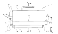
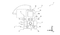
図2~図4に示すように、本実施形態に係る光照射装置1は、光ファイバ(線材)200に向けて光を照射する光源ユニット2と、光ファイバ200が挿入される挿入ユニット3とを備えている。また、光照射装置1は、光源ユニット2と挿入ユニット3とを回転軸4aで回転可能に接続する接続部4を備えている。
光源ユニット2は、光ファイバ200に向けて光を照射する光源21と、光源21を冷却する光源冷却部22と、光源21等を収容する筐体23とを備えている。また、光源ユニット2は、光源21に電力を供給するための電力供給部24を備えている。
光源21は、光ファイバ200の延びる方向(搬送方向)D1に沿って、長尺に形成されている。そして、光源21は、光ファイバ200に対面するように配置している。本実施形態においては、光源21は、紫外線硬化性の樹脂を硬化させるために、紫外光(例えば、波長が300nm~400nmの光)を出射している。
光源冷却部22は、光源21に連結され且つ冷却水が内部を流通する冷却本体22aと、冷却本体22aに冷却水を流入するための流入部22bと、冷却本体22aから冷却水を流出するための流出部22cとを備えている。なお、冷却本体22aは、筐体23の内部に配置され、流入部22b及び流出部22cは、筐体23の外部に配置されている。
筐体23は、光源21から放射された光を透過する透光部23aと、光を遮光する遮光部23bとを備えている。透光部23aは、光ファイバ200の延びる方向(搬送方向)D1に沿って、長尺に形成されている。そして、透光部23aは、光源21と対面するように配置されている。これにより、透光部23aは、光源21と光ファイバ200との間に配置されている。
電力供給部24は、外部からの電力を供給するために、例えば、ケーブル等が接続される電源接続部24aと、電源接続部24aと光源21との間を電気的に接続するために、各種の端子を有する端子台24bとを備えている。なお、電源接続部24aは、筐体23の外部に配置され、端子台24bは、筐体23の内部に配置されている。
挿入ユニット3は、光ファイバ200が内部に挿入される本体部5と、光ファイバ200を本体部5の内部に挿入するための挿入路61を、内部に形成する挿入部6と、挿入部6を本体部5に固定する固定部7とを備えている。また、挿入ユニット3は、本体部5を冷却する本体冷却部8を備えている。
固定部7は、挿入部6を挟持する一対の挟持部71,72を備えている。そして、固定部7は、一対の挟持部71,72が挿入部6の長手方向の端部を挟持することで、挿入部6の長手方向の端部と本体部5の長手方向の端部とを固定している。
本体冷却部8は、本体部5に連結され且つ冷却水が内部を流通する冷却本体8aと、冷却本体8aに冷却水を流入するための流入部8bと、冷却本体8aから冷却水を流出するための流出部8cとを備えている。そして、本体冷却部8(冷却本体8a)は、本体部5に対して着脱可能に構成されている。
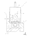
図4及び図5に示すように、本体部5は、光ファイバ200の延びる方向(搬送方向)D1に沿って、長尺に形成されている。また、本体部5は、長手方向に沿って、光ファイバ200が内部に挿入される凹状部51を備えている。そして、凹状部51は、円弧状に形成される内面に、光を反射する第1反射部52を備えている。また、凹状部51は、第1反射部52の周方向の一方側に、開口部53を一つ備えている。
第1反射部52は、光ファイバ200の延びる方向(搬送方向)D1に沿って、長尺に形成されている。そして、第1反射部52は、曲面で形成されている。具体的には、第1反射部52は、長手方向に対する直交面による断面において、真円形の一部からなる円弧状に形成されている。そして、第1反射部52は、挿入部6が内部に挿入できる大きさに、形成されている。
開口部53は、光ファイバ200の延びる方向(搬送方向)D1に沿って、長尺に形成されている。そして、開口部53は、透光部23aに覆われており、光源21と対面するように配置されている。これにより、光源21の光は、透光部23a及び開口部53を経由して、第1反射部52の内部の光ファイバ200に照射されている。したがって、光源21は、光ファイバ200の周方向の一方側から光ファイバ200に向けて光を照射している。
挿入部6は、内部に挿入路61を形成する挿入孔62を備えており、挿入孔62は、第1反射部52の内部及び外部に配置されている。具体的には、挿入部6が、透光性を有する筒状体で形成され、光ファイバ200の延びる方向(搬送方向)D1に沿って長尺に形成されることで、挿入孔62は、第1反射部52の内部及び外部に亘って配置されている。そして、挿入孔62は、長手方向に対する直交面による断面において、円形状に形成されている。即ち、挿入孔62は、内部に、円形状の挿入路61を形成している。
本実施形態においては、挿入部6は、石英管としており、挿入部6の内部に、窒素が充填されている。これにより、紫外線硬化性の樹脂が硬化する際の重合反応が酸素によって阻害されることが抑制でき、樹脂の硬化反応を促進する効果がある。また、光ファイバ200の表面の樹脂が硬化する際に、揮発物が生じるため、挿入部6は、当該揮発物が光源ユニット2(透光部23a)及び第1反射部52に付着することを防止している。
図5に示すように、第1反射部52は、円弧状の中心52aが挿入路61の中心61aに対して偏心するように、配置されている。換言すると、挿入部6(挿入孔62)は、挿入路61の中心61aが第1反射部52の円弧状の中心52aに対して偏心するように、配置されている。
そして、第1反射部52は、中心52aが挿入路61の中心61aに対して光源21からの出射光の光軸方向L1(光源21と接離する方向)に偏心するように、配置されている。換言すると、挿入部6(挿入孔62)は、挿入路61の中心61aが第1反射部52の円弧状の中心52aに対して光軸方向L1に偏心するように、配置されている。
さらに、第1反射部52は、中心52aが挿入路61の中心61aよりも光源21に近づく方向に偏心するように、配置されている。換言すると、挿入部6(挿入孔62)は、挿入路61の中心61aが第1反射部52の中心52aに対して光源21から離れる方向に偏心するように、配置されている。
本実施形態においては、光源21及び第1反射部52の配置は、光軸方向L1に伸びる基軸で線対称になっている。なお、第1反射部52の円弧状の中心52aは、第1反射部52に内接する内接円の中心である。また、挿入路61の中心61aは、挿入路61を構成する面(本実施形態においては、挿入孔62の内面)に内接する内接円の中心である。
光源21は、光ファイバ200の周方向から光ファイバ200に向けて発光する発光部21aと、発光部21aを支持する基板21bと、平面状に形成される第2反射部21cを有する反射体21dとを備えている。そして、発光部21a、基板21b、及び反射体21d(第2反射部21c)は、それぞれ光ファイバ200の延びる方向(搬送方向)D1に沿って、長尺に形成されている。
発光部21aは、本実施形態において、固体光源素子(例えば、LED)としている。なお、発光部21aは、斯かる構成に限られないのは勿論であり、光ファイバ200に向けて発光する部材であればよい。また、基板21bの一方側の面に発光部21aが固定されており、基板21bの他方側の面は、光源冷却部22(具体的には、冷却本体22a)に固定されている。
反射体21dは、基板21bの一方側の面に固定されている。なお、反射体21は、基板21bの一方側の面に反射材からなる塗料を塗布されて形成されてもよく、また、ミラーを、基板21bの一方側の面に接着剤やボルト等で固定されてもよい。そして、反射体21dは、発光部21aを挟むようにして、一対備えられている。これにより、第2反射部21cは、発光部21aを挟むようにして、一対備えられている。
第2反射部21cは、第1反射部52の中心52aを向くように配置されている。具体的には、第2反射部21cは、光源21からの出射光の光軸方向L1と直交するように配置されている。そして、第2反射部21cの全体は、第1反射部52の周方向において、第1反射部52の端部52bと発光部21aの端部21eとの間に配置されている。
また、第2反射部21cは、光源21からの出射光の光軸方向L1において、第1反射部52の中心52aよりも光源21側に配置されている。そして、第2反射部21cは、光ファイバ200を照射することなく入射された光の一部を、光ファイバ200に向けて反射する。
なお、第2反射部21cは、発光部21aからの光が入射された際に、当該光を50%以上、好ましくは60%以上、より好ましくは70%以上、さらに好ましくは80%以上、反射するように、構成されている。また、第2反射部21cは、入射された光を、鏡面反射するように構成されてもよく、また、拡散反射するように構成されてもよい。
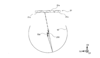
本実施形態に係る光照射装置1の構成については以上の通りであり、次に、線材200の中心が第1反射部52の円弧状の中心52aに対して偏心することによる作用効果の一例を図6及び図7を参酌して説明する。なお、線材200の中心は、挿入路61の中心61aに位置しているものとする。
まず、図6に係る実施例と図7に係る実施例とにおいては、発光部21aと第1反射部52との位置が、異なるものの、発光部21aと線材200との位置は、同じである。したがって、発光部21aから出射されて第1反射部52で反射されることなく線材200を直接に照射する光量は、同じである。
ところで、図6に係る実施例において、線材200の中心は、第1反射部52の円弧状の中心52aと一致している。斯かる構成において、光は、線材200の背面側(光源21と対面する面と反対側であって、図6及び図7における下面側)を照射するためには、第1反射部52の円弧状の中心52a付近を通過した後に、第1反射部52で反射する必要がある(図6の破線参照)。
しかしながら、第1反射部52の円弧状の中心52a付近を通過するような光は、線材200の正面側(発光部21aと対面する面であって、図6及び図7における上面側)を直接に照射してしまう(図6の2点鎖線参照)。したがって、図6に係る実施例においては、発光部21aから出射されて第1反射部52で反射された光は、それほど線材200を照射しない。
一方、図7に係る実施例において、線材200の中心は、第1反射部52の円弧状の中心52aに対して偏心している。斯かる構成において、光は、線材200の背面側を照射するために、線材200の位置を通過する必要がない。したがって、発光部21aから出射されて第1反射部52で反射された光の一部は、線材200の背面側を照射する。これにより、線材200の背面側も、線材200の正面側と同様に、光に照射される。
したがって、図6に係る実施例と図7に係る実施例とにおいては、発光部21aから出射されて線材200を直接に照射する光量は、同じであるものの、発光部21aから出射されて第1反射部52で反射された後に、線材200を照射する光量は、異なる。このように、線材200の中心が第1反射部52の円弧状の中心52aに対して偏心する構成が好ましい。即ち、挿入路61の中心61aが第1反射部52の円弧状の中心52aに対して偏心する構成が好ましい。
次に、第2反射部21cの配置による作用効果について、説明する。
第1反射部52は、円弧状に形成されている。そのため、光源21(発光部21a)から出射した光の光路は、第1反射部52で反射を繰り返して、再び、光源21側に戻りやすい。また、照射対象物である線材200の直径が比較的小さいこともあり、光源21から出射した光の多くが、第1反射部52で反射を繰り返すか、又は、光源21に吸収されてしまうため、光効率が良くない。
そこで、発光部21aの端部21eと第1反射部52の端部52bの間に、第2反射部21cが備えられることで、光源21側に戻ってくる光の光路を線材200側に向けることができる。これにより、光効率を高めることができる。
斯かる作用効果の一例を、図8及び図9を参酌して説明する。
図8に係る実施例においては、一方の反射体9の第2反射部9aと第1反射部52の径方向(具体的には、第1反射部52の中心52aから第2反射部9aに向かう第1反射部52の径方向)との交差角度θ1は、0°であり、他方の反射体10の第2反射部10aと第1反射部52の径方向との交差角度θ1は、90°である。また、図9に係る実施例においては、第2反射部21cと第1反射部52の径方向との交差角度θ1は、0°より大きく且つ90°より小さくなっている(図9においては、約60°となっている)。
なお、交差角度θ1の基準となる第1反射部52の径方向は、第2反射部9a,10a,21cの中心を通る第1反射部52の径方向である。また、一方の反射体9の第2反射部9aのように、第1反射部52側を向き且つ第1反射部52の径方向に沿って配置されている場合に、交差角度θ1は、0°である。そして、交差角度θ1が0°である位置から第2反射部52,9a,10a,21cが第1反射部52の中心52aと対面するように回転する方向が、交差角度θ1が増加する方向である。
例えば、一方の反射体9の第2反射部9aにおいては、時計回りの方向が、交差角度θ1が増加する方向であり、他方の反射体10の第2反射部10aにおいては、反時計回りの方向が、交差角度θ1が増加する方向である。なお、交差角度θ1は、0°~360°(=0°)まで存在する。
図8に係る実施例において、例えば、線材200の周りを進行する光が、一方(図8の右側)の第2反射部9aで反射すると、当該光の多くは、第1反射部52に向けて進行する。このように、第2反射部9aの交差角度θ1が約270°~360°(0°)の場合には、線材200の周りを進行する光が、第2反射部9aで反射すると、当該光の多くは、第1反射部52に向けて進行する。
また、例えば、線材200の周りを進行する光が、他方(図8の左側)の第2反射部9aで反射すると、当該光の多くは、第1反射部52の中心52aから離れるように進行する。このように、第2反射部9aの交差角度θ1が90°~約180°の場合には、線材200の周りを進行する光が、第2反射部9aで反射すると、当該光の多くは、第1反射部52の中心52aから離れるように進行する。なお、第2反射部9aの交差角度θ1が約180°~約270°の場合には、線材200の周りを進行する光は、第2反射部9aに入射され難い。
一方、図9に係る実施例において、線材200の周りを進行する光が、第2反射部21cで反射すると、当該光の多くは、第1反射部52の中心52aに向けて進行する。このように、第2反射部21cの交差角度θ1が0°より大きく且つ90°より小さい場合には、線材200の周りを進行する光が、第2反射部21cで反射すると、当該光の多くは、第1反射部52の中心52a、即ち、線材200に向けて進行する。
したがって、第2反射部21cの交差角度θ1が0°より大きく且つ90°より小さい場合には、線材200の周りを進行する光が、第2反射部21cで反射した後、当該光の一部は、線材200を照射することになる。このように、第2反射部21cの交差角度θ1が0°より大きく且つ90°より小さいことにより、光効率を効率的に向上させることができる。
よって、第2反射部21cの交差角度θ1は、0°より大きく且つ90°より小さい構成が好ましい。なお、第2反射部21cの交差角度θ1は、斯かる構成に限定されないのは勿論である。また、光源21の出射光の光軸方向L1と直交方向に対して、第2反射部21が交差する角度は、30°以下である構成が好ましい。なお、図9に係る実施例においては、当該角度は、0°である。
また、第2反射部21cの配置による別の作用効果について、説明する。
線材200は、発光部21aからの直接照射光と、第1反射部52での反射光と、第2反射部21cでの反射光とで、照射される。即ち、光源21は、発光部21aと第2反射部21cとを組み合わせることで、実質的に、光を出射する面積を広げることができている。これにより、比較的広域に光を出射することができるため、線材200が振動することで、線材200の位置がシフトしても、線材200に照射される光量の変動を抑えることができ、その結果、高い光効率を維持することができる。
したがって、発光部21aの幅寸法を小さくした場合でも、第2反射部21cを配置することにより、線材200が振動することで位置をシフトしても、高い光効率を維持することができる。なお、発光部21aの中央から、光源21からの出射光の光軸方向L1に向けた位置に、線材200を配置することで、発光部21aからの直接照射光の光量が最大となる。したがって、斯かる構成を採用することで、光効率を効果的に向上させることができる。
以上より、本実施形態に係る光照射装置1は、円弧状に形成される凹状の内面に配置され、線材200が内部に挿入される第1反射部52と、前記線材200の周方向から前記線材200に向けて発光する少なくとも一つ(本実施形態においては、一つ)の発光部21aと、平面状に形成される第2反射部21cと、を備え、前記第2反射部21cの少なくとも一部(本実施形態においては、全体)は、前記第1反射部52の周方向において、前記第1反射部52の端部52bと前記発光部21aの端部21eとの間に配置される。
斯かる構成によれば、第1反射部52は、円弧状に形成される凹状の内面に配置されている。そして、線材200は、第1反射部52の内部に挿入され、少なくとも一つ(本実施形態においては、一つ)の発光部21aは、線材200の周方向から線材200に向けて発光している。
また、第2反射部21cは、平面状に形成されている。そして、第2反射部21cの少なくとも一部(本実施形態においては、全体)は、第1反射部52の周方向において、第1反射部52の端部52bと発光部21aの端部21eとの間に配置されている。
これにより、第1反射部52の端部52bと発光部21aの端部21eとの間に進行した光が、第2反射部21cで反射されるため、第2反射部21cで反射された光の一部は、線材200に向けて進行し、線材200を照射する。したがって、光効率を向上させることができる。
また、本実施形態に係る光照射装置1においては、前記第2反射部21cは、前記第1反射部52の径方向との交差角度θ1が0°より大きく且つ90°より小さくなるように、配置される、という構成である。
斯かる構成によれば、第2反射部21cと第1反射部52の径方向との交差角度θ1は、0°より大きく、且つ、90°より小さくなっている。これにより、例えば、第1反射部52で反射を繰り返して線材200の周りを進行する光が、第2反射部21cで反射することで、当該光の一部は、線材200に向けて進行し、線材200を照射する。したがって、光効率をさらに向上させることができる。
また、本実施形態に係る光照射装置1においては、前記線材200を前記第1反射部52の内部に挿入するための挿入路61を、内部に形成する挿入部6を、備え、前記第1反射部52は、中心52aが前記挿入路61の中心61aに対して偏心するように、配置される、という構成である。
斯かる構成によれば、挿入部6は、線材200を第1反射部52の内部に挿入するための挿入路61を、内部に形成している。そして、第1反射部52の中心52aが、挿入路61の中心61aに対して偏心しているため、線材200は、第1反射部52の中心52aから外れて位置している。これにより、発光部21aから発して第1反射部52で反射した光の一部は、線材200に向けて進行し、線材200を照射する。したがって、光効率を効率的に向上させることができる。
なお、光照射装置は、上記した実施形態の構成に限定されるものではなく、また、上記した作用効果に限定されるものではない。また、光照射装置は、本発明の要旨を逸脱しない範囲内において種々変更を加え得ることは勿論である。例えば、下記する各種の変更例に係る構成や方法等を任意に一つ又は複数選択して、上記した実施形態に係る構成や方法等に採用してもよいことは勿論である。
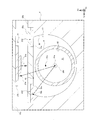
上記実施形態に係る光照射装置1においては、第2反射部21cの全体は、第1反射部52の周方向において、第1反射部52の端部52bと発光部21aの端部21eとの間に配置されている、という構成である。しかしながら、光照射装置は、斯かる構成に限られない。例えば、図10に示すように、第2反射部23cの一部は、第1反射部52の周方向において、第1反射部52の端部52bと発光部21aの端部21eとの間に配置されている、という構成でもよい。
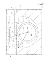
また、上記実施形態に係る光照射装置1においては、第1反射部52を有する部材5と、第2反射部21cを有する部材2とは、異なる、という構成である。しかしながら、光照射装置は、斯かる構成に限られない。例えば、図11に示すように、第1反射部52を有する部材5と、第2反射部54aを有する部材5とは、同じ、という構成でもよい。即ち、第1反射部52と第2反射部54aとは、一体に形成されている、という構成でもよい。
また、上記実施形態に係る光照射装置1においては、第2反射部21cは、光源21に備えられている、という構成である。しかしながら、光照射装置は、斯かる構成に限られない。例えば、図10に示すように、第2反射部23cは、筐体23が有する反射体23dに、備えられている、という構成でもよく、また、例えば、図11に示すように、第2反射部54aは、本体部5が有する凸状の反射体54に、備えられている、という構成でもよい。
また、上記実施形態に係る光照射装置1においては、第2反射部21cを有する反射体21dは、基板21bに固定されている、という構成である。しかしながら、光照射装置は、斯かる構成に限られない。例えば、図12に示すように、第2反射部21cを有する反射体21dは、光源冷却部22(具体的には、冷却本体22a)に固定されている、という構成でもよい。また、例えば、図13に示すように、第2反射部21cを有する反射体21dは、基板21bを光源冷却部22に保持させる保持体21fに、固定されている、という構成でもよい。
また、上記実施形態に係る光照射装置1においては、第1反射部52は、真円形の一部からなる円弧状に形成されている、という構成である。しかしながら、光照射装置は、斯かる構成に限られない。例えば、図14に示すように、第1反射部52は、楕円形の一部からなる円弧状に形成されている、という構成でもよく、また例えば、図15に示すように、第1反射部52は、複数の平面が円弧状に配置されることで、形成されている、即ち、多角形で形成されている、という構成でもよい。
そして、第1反射部52は、線材200が内部に挿入できる大きさに、形成されていればよい。また、例えば、第1反射部52は、円形状の一部である円弧状に形成される構成だけでなく、円形状の全部である円弧状(即ち、円形状)で形成される構成でもよい。
ところで、「円弧状に形成される凹状の内面に配置される第1反射部」における「円弧状」は、中心C0の位置が同じ2つ円(第1円C1及び第2円C2)の間に入る形状であって、第1円C1の直径と第2円C2の直径(≧第1円C1の直径)との関係が以下の式を満たすことをいう。
100% ≦ (第2円C2の直径)/(第1円C1の直径) ≦ 110%
また、好ましくは、以下の式を満たすこととしてもよい。
100% ≦ (第2円C2の直径)/(第1円C1の直径) ≦ 105%
100% ≦ (第2円C2の直径)/(第1円C1の直径) ≦ 110%
また、好ましくは、以下の式を満たすこととしてもよい。
100% ≦ (第2円C2の直径)/(第1円C1の直径) ≦ 105%
なお、第1反射部52の円弧状の中心52aの位置は、「(第2円C2の直径)/(第1円C1の直径)」が最小となる場合の、前記各円C1,C2の中心C0の位置である。また、例えば、図14に示すように、第1反射部52は、第1円C1と第2円C2の間に入る楕円形の、その一部からなる形状であってもよい。
また、上記実施形態に係る光照射装置1においては、挿入孔62は、円形状に形成されている、という構成である。しかしながら、光照射装置は、斯かる構成に限られない。例えば、挿入孔62は、楕円形状に形成されている、という構成でもよく、また、例えば、図16に示すように、挿入孔62は、多角形状に形成されている、という構成でもよい。なお、挿入路61の中心61aは、挿入路61を構成する面に内接する内接円(図16においては、円C3)の中心である。
また、上記実施形態に係る光照射装置1においては、挿入路61は、第1反射部52とは別の構成である挿入孔62で構成される、という構成である。しかしながら、光照射装置は、斯かる構成に限られない。例えば、光照射装置は、斯かる挿入孔62を備えておらず、図17に示すように、第1反射部52は、挿入部6の少なくとも一部を構成し、且つ、中心52aが挿入路61の中心61aに対して偏心するように、形成される、という構成でもよい。
図17に係る挿入部6は、第1反射部52と光源ユニット2の透光部23aとで構成されている。そして、挿入路61は、第1反射部52と透光部23aとで構成される内空間で構成されている。なお、挿入路61の中心61aは、挿入路61を構成する面(図17においては、第1反射部52及び透光部23aの面)に内接する内接円C4の中心である。
また、上記実施形態に係る光照射装置1においては、挿入部6が、長尺な筒状に形成され、第1反射部52の内部及び外部に配置されることで、挿入孔62は、第1反射部52の内部及び外部に配置されている、という構成である。しかしながら、光照射装置は、斯かる構成に限られない。例えば、挿入孔62は、第1反射部52の内部のみに配置されている、という構成でもよく、また、例えば、挿入部6が固定部7に固定される周辺部分のみに配置されることで、挿入孔62は、第1反射部52の外部のみに配置されている、という構成でもよい。
また、上記実施形態に係る光照射装置1においては、発光部21a(光源21)は、一つ備えられている、という構成である。しかしながら、光照射装置は、斯かる構成に限られない。例えば、発光部21a(光源21)は、複数備えられている、という構成でもよい。
また、上記実施形態に係る光照射装置1においては、第1反射部52は、中心52aが挿入路61の中心61aに対して偏心するように、配置されている、という構成である。しかしながら、光照射装置は、斯かる構成に限られない。例えば、第1反射部52は、中心52aが挿入路61の中心61aと一致するように、配置されている、という構成でもよい。
また、上記実施形態に係る光照射装置1においては、線材200は、光ファイバである、という構成である。しかしながら、光照射装置は、斯かる構成に限られない。例えば、線材200は、繊維である、という構成でもよい。具体的には、光照射装置は、繊維である線材200に紫外光を照射することで、繊維の表面改質を行う装置であってもよい。
また、上記実施形態に係る光照射装置1においては、線材200は、光照射装置1の内部を走行する状態で、光を照射される、という構成である。しかしながら、光照射装置は、斯かる構成に限られない。例えば、線材200は、光照射装置1に対して固定された状態で、光を照射される、という構成でもよい。
また、光照射装置1においては、線材200の中心(挿入路61の中心61a)が第1反射部52の円弧状の中心52aに対して偏心する量は、線材200の半径よりも大きい、という構成が好ましく、さらに、線材200の直径よりも大きい、という構成がより好ましい。斯かる構成によれば、第1反射部52の円弧状の中心52aが、線材200の外部に位置することになるため、光効率をより向上させることができる。
1…光照射装置、2…光源ユニット、3…挿入ユニット、4…接続部、4a…回転軸、5…本体部、6…挿入部、7…固定部、8…本体冷却部、8a…冷却本体、8b…流入部、8c…流出部、9…反射体、9a…第2反射部、10…反射体、10a…第2反射部、21…光源、21a…発光部、21b…基板、21c…第2反射部、21d…反射体、21e…端部、21f…保持体、22…光源冷却部、22a…冷却本体、22b…流入部、22c…流出部、23…筐体、23a…透光部、23b…遮光部、23c…第2反射部、23d…反射体、24…電力供給部、24a…電源接続部、24b…端子台、51…凹状部、52…第1反射部、52a…中心、52b…端部、53…開口部、54…反射体、54a…第2反射部、61…挿入路、61a…中心、62…挿入孔、71…挟持部、72…挟持部、100…光ファイバ製造装置、110…搬送装置、111…搬送部材、112…搬送部材、120…塗布装置、200…線材(光ファイバ)
Claims (3)
- 円弧状に形成される凹状の内面に配置され、線材が内部に挿入される第1反射部と、
前記線材の周方向から前記線材に向けて発光する少なくとも一つの発光部と、
平面状に形成される第2反射部と、を備え、
前記第2反射部の少なくとも一部は、前記第1反射部の周方向において、前記第1反射部の端部と前記発光部の端部との間に配置される、光照射装置。 - 前記第2反射部は、前記第1反射部の径方向との交差角度が0°より大きく且つ90°より小さくなるように、配置される、請求項1に記載の光照射装置。
- 前記線材を前記第1反射部の内部に挿入するための挿入路を、内部に形成する挿入部を、備え、
前記第1反射部は、中心が前記挿入路の中心に対して偏心するように、配置される、請求項1又は2に記載の光照射装置。
Priority Applications (2)
| Application Number | Priority Date | Filing Date | Title |
|---|---|---|---|
| CN201780051976.3A CN109641791B (zh) | 2016-09-02 | 2017-08-31 | 光照射装置 |
| US16/329,359 US11440840B2 (en) | 2016-09-02 | 2017-08-31 | Light irradiation device |
Applications Claiming Priority (2)
| Application Number | Priority Date | Filing Date | Title |
|---|---|---|---|
| JP2016-171891 | 2016-09-02 | ||
| JP2016171891A JP6816413B2 (ja) | 2016-09-02 | 2016-09-02 | 光照射装置 |
Publications (1)
| Publication Number | Publication Date |
|---|---|
| WO2018043656A1 true WO2018043656A1 (ja) | 2018-03-08 |
Family
ID=61301000
Family Applications (1)
| Application Number | Title | Priority Date | Filing Date |
|---|---|---|---|
| PCT/JP2017/031411 Ceased WO2018043656A1 (ja) | 2016-09-02 | 2017-08-31 | 光照射装置 |
Country Status (4)
| Country | Link |
|---|---|
| US (1) | US11440840B2 (ja) |
| JP (1) | JP6816413B2 (ja) |
| CN (1) | CN109641791B (ja) |
| WO (1) | WO2018043656A1 (ja) |
Families Citing this family (1)
| Publication number | Priority date | Publication date | Assignee | Title |
|---|---|---|---|---|
| US11773016B2 (en) * | 2018-12-14 | 2023-10-03 | Corning Incorporated | Diffuse reflector and methods of use |
Citations (5)
| Publication number | Priority date | Publication date | Assignee | Title |
|---|---|---|---|---|
| JPH05254894A (ja) * | 1992-03-13 | 1993-10-05 | Furukawa Electric Co Ltd:The | 紫外線照射装置 |
| US20150028020A1 (en) * | 2013-07-23 | 2015-01-29 | Phoseon Technology, Inc. | Compound Elliptical Reflector for Curing Optical Fibers |
| JP2016004927A (ja) * | 2014-06-18 | 2016-01-12 | 株式会社オーク製作所 | 紫外線照射装置 |
| WO2017104292A1 (ja) * | 2015-12-18 | 2017-06-22 | ウシオ電機株式会社 | 光照射装置及び光照射方法 |
| JP2017171531A (ja) * | 2016-03-23 | 2017-09-28 | 住友電気工業株式会社 | 線条体の被覆方法および被覆装置 |
Family Cites Families (11)
| Publication number | Priority date | Publication date | Assignee | Title |
|---|---|---|---|---|
| JP3005955B2 (ja) * | 1998-04-17 | 2000-02-07 | スタンレー電気株式会社 | 灯 具 |
| US7399982B2 (en) | 2003-01-09 | 2008-07-15 | Con-Trol-Cure, Inc | UV curing system and process with increased light intensity |
| JP2004259541A (ja) * | 2003-02-25 | 2004-09-16 | Cateye Co Ltd | 照明器具 |
| US7658513B2 (en) * | 2005-03-03 | 2010-02-09 | Dialight Corporation | LED illumination device with a highly uniform illumination pattern |
| WO2007022314A2 (en) * | 2005-08-17 | 2007-02-22 | Illumination Management Solutions, Inc. | An improved optic for leds and other light sources |
| ITRE20060052A1 (it) * | 2006-04-28 | 2007-10-29 | Incerti Simonini Snc | DISPOSITIVO OTTICO SECONDARIO PER LAMPADE A LEDs |
| TWI308627B (en) * | 2006-12-05 | 2009-04-11 | Ind Tech Res Inst | Illumination device of flexible lighting angle |
| GB0623796D0 (en) * | 2006-11-29 | 2007-01-10 | Qinetiq Ltd | Reflector assembly and beam forming apparatus |
| TWM334262U (en) * | 2007-10-12 | 2008-06-11 | Dosun Solar Technology Co Ltd | Light-emitting diode (LED) lighting fixture having light beam adjustment |
| JP2012043548A (ja) * | 2010-08-13 | 2012-03-01 | Thermo Riko:Kk | 高効率赤外線導入加熱装置 |
| KR101551312B1 (ko) * | 2014-05-15 | 2015-09-08 | 제이더블유중외메디칼 주식회사 | 리플렉터 무영등의 멀티 싱크 포커싱 장치 |
-
2016
- 2016-09-02 JP JP2016171891A patent/JP6816413B2/ja active Active
-
2017
- 2017-08-31 WO PCT/JP2017/031411 patent/WO2018043656A1/ja not_active Ceased
- 2017-08-31 US US16/329,359 patent/US11440840B2/en active Active
- 2017-08-31 CN CN201780051976.3A patent/CN109641791B/zh active Active
Patent Citations (5)
| Publication number | Priority date | Publication date | Assignee | Title |
|---|---|---|---|---|
| JPH05254894A (ja) * | 1992-03-13 | 1993-10-05 | Furukawa Electric Co Ltd:The | 紫外線照射装置 |
| US20150028020A1 (en) * | 2013-07-23 | 2015-01-29 | Phoseon Technology, Inc. | Compound Elliptical Reflector for Curing Optical Fibers |
| JP2016004927A (ja) * | 2014-06-18 | 2016-01-12 | 株式会社オーク製作所 | 紫外線照射装置 |
| WO2017104292A1 (ja) * | 2015-12-18 | 2017-06-22 | ウシオ電機株式会社 | 光照射装置及び光照射方法 |
| JP2017171531A (ja) * | 2016-03-23 | 2017-09-28 | 住友電気工業株式会社 | 線条体の被覆方法および被覆装置 |
Also Published As
| Publication number | Publication date |
|---|---|
| US20190249846A1 (en) | 2019-08-15 |
| CN109641791B (zh) | 2022-02-18 |
| JP6816413B2 (ja) | 2021-01-20 |
| JP2018035050A (ja) | 2018-03-08 |
| CN109641791A (zh) | 2019-04-16 |
| US11440840B2 (en) | 2022-09-13 |
Similar Documents
| Publication | Publication Date | Title |
|---|---|---|
| JP6266932B2 (ja) | 車両用灯具 | |
| WO2018230546A1 (ja) | 光照射装置、光照射方法 | |
| JP4458359B2 (ja) | レンズおよびレンズユニット並びにそれらを具備する灯具 | |
| JP2016100286A (ja) | 車両用灯具、照明装置、および発光装置 | |
| JP5334724B2 (ja) | 導光体 | |
| JP2013543215A (ja) | 狭ビームサイズと高ルーメン出力とを有するセグメント化スポットライト | |
| JP6878762B2 (ja) | 光照射装置及び光照射方法 | |
| WO2018043656A1 (ja) | 光照射装置 | |
| WO2017104292A1 (ja) | 光照射装置及び光照射方法 | |
| JP2018507119A (ja) | 自動車の運転時にドライバーをサポートする又は自動車を自律的に運転するための装置 | |
| JP2018507119A6 (ja) | Uv光硬化システム並びにuv光硬化システムを設計し動作させる方法 | |
| US20180051855A1 (en) | Lighting device and lighting system | |
| JP6853943B2 (ja) | 光照射装置 | |
| JP6763450B2 (ja) | 光照射装置 | |
| JP6857334B2 (ja) | 光照射装置 | |
| JP6815942B2 (ja) | 光照射装置、光照射方法 | |
| JP6614413B2 (ja) | 光源装置及びその製造方法 | |
| JP4632311B2 (ja) | 照明装置 | |
| JP2020057571A (ja) | 光学系装置、両凸レンズ | |
| JP6639573B2 (ja) | 照明ランプ | |
| JP2019003107A5 (ja) | ||
| JP5368039B2 (ja) | 照明装置 | |
| KR20040106832A (ko) | 도광판 및 반사부재를 사용한 차량용 램프 | |
| JP2015022963A (ja) | 車両用導光部材、車両用灯具 | |
| WO2018207380A1 (ja) | 光学素子および光学系装置 |
Legal Events
| Date | Code | Title | Description |
|---|---|---|---|
| 121 | Ep: the epo has been informed by wipo that ep was designated in this application |
Ref document number: 17846660 Country of ref document: EP Kind code of ref document: A1 |
|
| NENP | Non-entry into the national phase |
Ref country code: DE |
|
| 122 | Ep: pct application non-entry in european phase |
Ref document number: 17846660 Country of ref document: EP Kind code of ref document: A1 |