WO2018043552A1 - 電子内視鏡用プロセッサ及び電子内視鏡システム - Google Patents
電子内視鏡用プロセッサ及び電子内視鏡システム Download PDFInfo
- Publication number
- WO2018043552A1 WO2018043552A1 PCT/JP2017/031126 JP2017031126W WO2018043552A1 WO 2018043552 A1 WO2018043552 A1 WO 2018043552A1 JP 2017031126 W JP2017031126 W JP 2017031126W WO 2018043552 A1 WO2018043552 A1 WO 2018043552A1
- Authority
- WO
- WIPO (PCT)
- Prior art keywords
- color
- processor
- pixel data
- image
- electronic endoscope
- Prior art date
- Legal status (The legal status is an assumption and is not a legal conclusion. Google has not performed a legal analysis and makes no representation as to the accuracy of the status listed.)
- Ceased
Links
Images



Classifications
-
- A—HUMAN NECESSITIES
- A61—MEDICAL OR VETERINARY SCIENCE; HYGIENE
- A61B—DIAGNOSIS; SURGERY; IDENTIFICATION
- A61B1/00—Instruments for performing medical examinations of the interior of cavities or tubes of the body by visual or photographical inspection, e.g. endoscopes; Illuminating arrangements therefor
- A61B1/04—Instruments for performing medical examinations of the interior of cavities or tubes of the body by visual or photographical inspection, e.g. endoscopes; Illuminating arrangements therefor combined with photographic or television appliances
- A61B1/045—Control thereof
-
- G—PHYSICS
- G06—COMPUTING OR CALCULATING; COUNTING
- G06T—IMAGE DATA PROCESSING OR GENERATION, IN GENERAL
- G06T7/00—Image analysis
- G06T7/0002—Inspection of images, e.g. flaw detection
- G06T7/0012—Biomedical image inspection
-
- A—HUMAN NECESSITIES
- A61—MEDICAL OR VETERINARY SCIENCE; HYGIENE
- A61B—DIAGNOSIS; SURGERY; IDENTIFICATION
- A61B1/00—Instruments for performing medical examinations of the interior of cavities or tubes of the body by visual or photographical inspection, e.g. endoscopes; Illuminating arrangements therefor
- A61B1/00002—Operational features of endoscopes
- A61B1/00004—Operational features of endoscopes characterised by electronic signal processing
- A61B1/00009—Operational features of endoscopes characterised by electronic signal processing of image signals during a use of endoscope
-
- A—HUMAN NECESSITIES
- A61—MEDICAL OR VETERINARY SCIENCE; HYGIENE
- A61B—DIAGNOSIS; SURGERY; IDENTIFICATION
- A61B1/00—Instruments for performing medical examinations of the interior of cavities or tubes of the body by visual or photographical inspection, e.g. endoscopes; Illuminating arrangements therefor
- A61B1/00002—Operational features of endoscopes
- A61B1/00004—Operational features of endoscopes characterised by electronic signal processing
- A61B1/00009—Operational features of endoscopes characterised by electronic signal processing of image signals during a use of endoscope
- A61B1/000094—Operational features of endoscopes characterised by electronic signal processing of image signals during a use of endoscope extracting biological structures
-
- A—HUMAN NECESSITIES
- A61—MEDICAL OR VETERINARY SCIENCE; HYGIENE
- A61B—DIAGNOSIS; SURGERY; IDENTIFICATION
- A61B1/00—Instruments for performing medical examinations of the interior of cavities or tubes of the body by visual or photographical inspection, e.g. endoscopes; Illuminating arrangements therefor
- A61B1/00002—Operational features of endoscopes
- A61B1/00004—Operational features of endoscopes characterised by electronic signal processing
- A61B1/00009—Operational features of endoscopes characterised by electronic signal processing of image signals during a use of endoscope
- A61B1/000095—Operational features of endoscopes characterised by electronic signal processing of image signals during a use of endoscope for image enhancement
-
- A—HUMAN NECESSITIES
- A61—MEDICAL OR VETERINARY SCIENCE; HYGIENE
- A61B—DIAGNOSIS; SURGERY; IDENTIFICATION
- A61B1/00—Instruments for performing medical examinations of the interior of cavities or tubes of the body by visual or photographical inspection, e.g. endoscopes; Illuminating arrangements therefor
- A61B1/00002—Operational features of endoscopes
- A61B1/00004—Operational features of endoscopes characterised by electronic signal processing
- A61B1/00009—Operational features of endoscopes characterised by electronic signal processing of image signals during a use of endoscope
- A61B1/000096—Operational features of endoscopes characterised by electronic signal processing of image signals during a use of endoscope using artificial intelligence
-
- A—HUMAN NECESSITIES
- A61—MEDICAL OR VETERINARY SCIENCE; HYGIENE
- A61B—DIAGNOSIS; SURGERY; IDENTIFICATION
- A61B1/00—Instruments for performing medical examinations of the interior of cavities or tubes of the body by visual or photographical inspection, e.g. endoscopes; Illuminating arrangements therefor
- A61B1/04—Instruments for performing medical examinations of the interior of cavities or tubes of the body by visual or photographical inspection, e.g. endoscopes; Illuminating arrangements therefor combined with photographic or television appliances
- A61B1/05—Instruments for performing medical examinations of the interior of cavities or tubes of the body by visual or photographical inspection, e.g. endoscopes; Illuminating arrangements therefor combined with photographic or television appliances characterised by the image sensor, e.g. camera, being in the distal end portion
-
- A—HUMAN NECESSITIES
- A61—MEDICAL OR VETERINARY SCIENCE; HYGIENE
- A61B—DIAGNOSIS; SURGERY; IDENTIFICATION
- A61B1/00—Instruments for performing medical examinations of the interior of cavities or tubes of the body by visual or photographical inspection, e.g. endoscopes; Illuminating arrangements therefor
- A61B1/06—Instruments for performing medical examinations of the interior of cavities or tubes of the body by visual or photographical inspection, e.g. endoscopes; Illuminating arrangements therefor with illuminating arrangements
- A61B1/0638—Instruments for performing medical examinations of the interior of cavities or tubes of the body by visual or photographical inspection, e.g. endoscopes; Illuminating arrangements therefor with illuminating arrangements providing two or more wavelengths
-
- A—HUMAN NECESSITIES
- A61—MEDICAL OR VETERINARY SCIENCE; HYGIENE
- A61B—DIAGNOSIS; SURGERY; IDENTIFICATION
- A61B5/00—Measuring for diagnostic purposes; Identification of persons
-
- G—PHYSICS
- G06—COMPUTING OR CALCULATING; COUNTING
- G06T—IMAGE DATA PROCESSING OR GENERATION, IN GENERAL
- G06T1/00—General purpose image data processing
-
- G—PHYSICS
- G06—COMPUTING OR CALCULATING; COUNTING
- G06T—IMAGE DATA PROCESSING OR GENERATION, IN GENERAL
- G06T1/00—General purpose image data processing
- G06T1/60—Memory management
-
- G—PHYSICS
- G06—COMPUTING OR CALCULATING; COUNTING
- G06T—IMAGE DATA PROCESSING OR GENERATION, IN GENERAL
- G06T3/00—Geometric image transformations in the plane of the image
- G06T3/02—Affine transformations
-
- H—ELECTRICITY
- H04—ELECTRIC COMMUNICATION TECHNIQUE
- H04N—PICTORIAL COMMUNICATION, e.g. TELEVISION
- H04N1/00—Scanning, transmission or reproduction of documents or the like, e.g. facsimile transmission; Details thereof
- H04N1/46—Colour picture communication systems
- H04N1/56—Processing of colour picture signals
- H04N1/60—Colour correction or control
-
- H—ELECTRICITY
- H04—ELECTRIC COMMUNICATION TECHNIQUE
- H04N—PICTORIAL COMMUNICATION, e.g. TELEVISION
- H04N1/00—Scanning, transmission or reproduction of documents or the like, e.g. facsimile transmission; Details thereof
- H04N1/46—Colour picture communication systems
- H04N1/56—Processing of colour picture signals
- H04N1/60—Colour correction or control
- H04N1/6002—Corrections within particular colour systems
- H04N1/6008—Corrections within particular colour systems with primary colour signals, e.g. RGB or CMY(K)
-
- H—ELECTRICITY
- H04—ELECTRIC COMMUNICATION TECHNIQUE
- H04N—PICTORIAL COMMUNICATION, e.g. TELEVISION
- H04N1/00—Scanning, transmission or reproduction of documents or the like, e.g. facsimile transmission; Details thereof
- H04N1/46—Colour picture communication systems
- H04N1/64—Systems for the transmission or the storage of the colour picture signal; Details therefor, e.g. coding or decoding means therefor
- H04N1/644—Systems for the transmission or the storage of the colour picture signal; Details therefor, e.g. coding or decoding means therefor using a reduced set of representative colours, e.g. each representing a particular range in a colour space
-
- H—ELECTRICITY
- H04—ELECTRIC COMMUNICATION TECHNIQUE
- H04N—PICTORIAL COMMUNICATION, e.g. TELEVISION
- H04N9/00—Details of colour television systems
- H04N9/64—Circuits for processing colour signals
- H04N9/67—Circuits for processing colour signals for matrixing
-
- G—PHYSICS
- G06—COMPUTING OR CALCULATING; COUNTING
- G06T—IMAGE DATA PROCESSING OR GENERATION, IN GENERAL
- G06T2207/00—Indexing scheme for image analysis or image enhancement
- G06T2207/10—Image acquisition modality
- G06T2207/10024—Color image
-
- G—PHYSICS
- G06—COMPUTING OR CALCULATING; COUNTING
- G06T—IMAGE DATA PROCESSING OR GENERATION, IN GENERAL
- G06T2207/00—Indexing scheme for image analysis or image enhancement
- G06T2207/10—Image acquisition modality
- G06T2207/10068—Endoscopic image
Definitions
- the present invention relates to an electronic endoscope processor and an electronic endoscope system.
- Patent Document 1 has a function of supporting endoscopic image diagnosis by identifying a region that is highly likely to be a lesion based on color information of an endoscopic image and highlighting the identified region. An electronic endoscope system is described.
- a conventional electronic endoscope system is provided with a white balance correction function as a function of correcting color information of an endoscope image.
- White balance correction is to perform color correction at only one point on the achromatic color axis (for example, white), so chromatic error cannot be corrected. For this reason, in a conventional electronic endoscope system having only a white balance correction function as a function for correcting color information, there is a large error in color information, which makes the accuracy of identifying a lesion or the like low.
- the present invention has been made in view of the above circumstances, and an object of the present invention is to provide an electronic device suitable for improving identification accuracy when identifying a lesion or the like based on a color component of an endoscopic image.
- An endoscope processor and an electronic endoscope system are provided.
- the processor for an electronic endoscope converts each pixel data constituting a color image of a living tissue in a body cavity composed of n (n ⁇ 3) types of color components into lesser than m types of pixel data.
- the electronic endoscope processor has less than n types of pixel data constituting a color image of a living tissue in a body cavity composed of n (n ⁇ 3) types of color components.
- conversion means for converting into pixel data consisting of m (m ⁇ 2) types of color components;
- acquisition means for acquiring an evaluation result relating to the target disease based on the converted pixel data of m types of color components;
- Evaluation result correction means for correcting the evaluation result using a predetermined evaluation result correction coefficient.
- the processor for an electronic endoscope is Conversion that converts each pixel data constituting a color image of a living tissue in a body cavity composed of n (n ⁇ 3) types of color components into pixel data composed of m (m ⁇ 2) types of color components fewer than n types Means, Obtaining means for obtaining an evaluation result relating to the target disease based on the converted pixel data composed of the m kinds of color components; Color component correction means for correcting the pixel data composed of the m kinds of color components converted by the conversion means using a predetermined color component correction coefficient, and the evaluation result acquired by the acquisition means as a predetermined evaluation result At least one correction means of the evaluation result correction means for correcting using the correction coefficient; It is preferable to provide.
- the electronic endoscope processor further includes a color component correction unit that corrects pixel data including m kinds of color components using a predetermined color component correction coefficient.
- the acquisition unit acquires an evaluation result related to the target disease based on pixel data including m types of color components corrected by the color component correction coefficient.
- the color component correction coefficient is preferably a predetermined correction matrix coefficient for correcting pixel data including m kinds of color components, for example.
- the evaluation result correction coefficient is preferably an affine transformation coefficient for affine transformation of the evaluation result, for example.
- the color components to be subjected to color correction performed by the color component correction unit are the m types of color components among the n types of color components, and (n ⁇ m) It is preferable not to contain any kind of color components.
- the acquisition unit sets a reference direction related to the target disease viewed from a predetermined reference point in a color space defined by the m types of color components. , For each pixel of the color image, based on the degree of deviation from the reference direction of the direction corresponding to the pixel corresponding point corresponding to the converted pixel data in the color space from the reference direction, the target disease It is preferable to obtain an evaluation result regarding
- the acquisition unit sets a reference axis related to a target disease that passes a predetermined reference point in a color plane defined by m kinds of color components, and each pixel It is preferable to obtain an evaluation result related to the target disease based on an angle formed by a line segment connecting the reference point and the pixel corresponding point corresponding to the pixel data and the reference axis.
- the acquisition means sets a second reference axis related to a healthy site that does not have the target disease and passes through the reference point in the color plane; It is preferable that the evaluation value is calculated by normalizing the angle ⁇ with the intersection angle between the first reference axis and the second reference axis as a maximum angle.
- the conversion unit orthogonally projects each pixel data in a color space defined by n types of color components onto a color plane.
- the reference axis is preferably an axis indicating an inflammatory site having the highest symptom level for the target disease, for example.
- the reference axis is preferably an axis on which the converted pixel corresponding points converge as the symptom level increases for the target disease.
- the color plane is preferably a plane including, for example, an R component axis and a G component axis.
- all of m types of color components of the converted pixel data are color components set so that wavelength bands are different from each other.
- the evaluation result includes, for example, at least one of a value indicating evaluation regarding the target disease and a color image indicating evaluation regarding the target disease.
- An electronic endoscope system includes at least two or more types of actual images obtained by photographing the above-described electronic endoscope processor and at least two or more indices related to a target disease.
- Color component correction coefficient calculating means for calculating a color component correction coefficient based on shooting data is provided.
- An electronic endoscope system acquires the evaluation result of each index by photographing each of the plurality of indices and the processor for electronic endoscope described above, and each acquired Evaluation result correction coefficient calculation means for calculating an evaluation result correction coefficient using the evaluation result of the index is provided.
- an electronic endoscope system is configured to display the above-described electronic endoscope processor and an evaluation result obtained by the electronic endoscope processor on a display screen.
- a display device A display device.
- the electronic endoscope processor converts the color of each pixel of the color image into a color corresponding to the evaluation value calculated as the evaluation result of each pixel.
- hue and saturation are removed from the color components.
- the electronic endoscope processor and the electronic endoscope system described above it is possible to improve the identification accuracy when identifying a lesioned part or the like based on the color component of the endoscope image.
- FIG. 1 is a block diagram showing a configuration of an electronic endoscope system 1 according to an embodiment of the present invention.
- the electronic endoscope system 1 is a system specialized for medical use, and includes an electronic scope 100, a processor 200, and a monitor 300.
- the processor 200 includes a system controller 202 and a timing controller 204.
- the system controller 202 executes various programs stored in the memory 222 and controls the entire electronic endoscope system 1 in an integrated manner.
- the system controller 202 is connected to the operation panel 218.
- the system controller 202 changes each operation of the electronic endoscope system 1 and parameters for each operation in accordance with an instruction from the operator input from the operation panel 218.
- the input instruction by the operator includes, for example, an instruction to switch the operation mode of the electronic endoscope system 1. In this embodiment, there are a normal mode, a special mode, and a calibration mode as operation modes.
- the timing controller 204 outputs a clock pulse for adjusting the operation timing of each unit to each circuit in the electronic endoscope system 1.
- the lamp 208 emits white light L after being started by the lamp power igniter 206.
- the lamp 208 is a high-intensity lamp such as a xenon lamp, a halogen lamp, a mercury lamp, or a metal halide lamp.
- the white light L emitted from the lamp 208 is limited to an appropriate amount of light through the diaphragm 212 while being collected by the condenser lens 210.
- the lamp 208 may be replaced with a semiconductor light emitting element such as an LD (Laser Diode) or an LED (Light Emitting Diode).
- LD Laser Diode
- LED Light Emitting Diode
- the semiconductor light emitting device has features such as low power consumption and small amount of heat generation compared to other light sources, there is an advantage that a bright image can be acquired while suppressing power consumption and heat generation amount. The ability to obtain a bright image leads to an improvement in the accuracy of the inflammation evaluation value described later.
- the semiconductor light emitting element is not limited to the processor 200 and may be incorporated in the electronic scope 100. As an example, the semiconductor light emitting element may be provided in the distal end portion of the electronic scope 100.
- the motor 214 is mechanically connected to the diaphragm 212 via a transmission mechanism such as an arm or gear not shown.
- the motor 214 is a DC motor, for example, and is driven under the drive control of the driver 216.
- the aperture 212 is operated by the motor 214 to change the opening degree so that the image displayed on the display screen of the monitor 300 has an appropriate brightness.
- the amount of white light L emitted from the lamp 208 is limited according to the opening degree of the diaphragm 212.
- the appropriate reference for the brightness of the image is changed according to the brightness adjustment operation of the operation panel 218 by the operator.
- the dimming circuit that controls the brightness by controlling the driver 216 is a well-known circuit and is omitted in this specification.
- the white light L that has passed through the stop 212 is condensed on the incident end face of an LCB (Light Carrying Bundle) 102 and is incident on the LCB 102.
- White light L incident on the LCB 102 from the incident end face propagates in the LCB 102.
- the white light L propagating through the LCB 102 is emitted from the emission end face of the LCB 102 disposed at the tip of the electronic scope 100 and irradiates the living tissue via the light distribution lens 104.
- the return light from the living tissue irradiated with the white light L forms an optical image on the light receiving surface of the solid-state image sensor 108 via the objective lens 106.
- the solid-state image sensor 108 is a single-plate color CCD (Charge-Coupled Device) image sensor equipped with a complementary color checkered filter.
- the solid-state image sensor 108 accumulates an optical image formed by each pixel on the light receiving surface as a charge corresponding to the amount of light, and generates and outputs pixel data of yellow Ye, cyan Cy, green G, and magenta Mg.
- the solid-state imaging element 108 is not limited to a CCD image sensor, and may be replaced with a CMOS (Complementary Meta1 Oxide Semiconductor) image sensor or other types of imaging devices.
- CMOS Complementary Meta1 Oxide Semiconductor
- the solid-state image sensor 108 may be one equipped with a primary color filter (Bayer array filter).
- the primary color (RGB) filter has better color development than the complementary color filter. For this reason, when an RGB image signal from an image sensor equipped with a primary color filter is used to calculate an inflammation evaluation value, which will be described later, the evaluation accuracy can be improved.
- a primary color filter it is not necessary to perform signal conversion in the inflammation evaluation value calculation process. Therefore, it is possible to suppress the processing load of the inflammation evaluation value calculation.
- a driver signal processing circuit 112 receives pixel data of each pixel obtained by imaging the living tissue irradiated with the white light L from the solid-state imaging device 108 in a frame cycle.
- the driver signal processing circuit 112 outputs pixel data input from the solid-state image sensor 108 to the signal processing circuit 220 of the processor 200.
- “frame” may be replaced with “field”.
- the frame period and the field period are 1/30 seconds and 1/60 seconds, respectively.
- the driver signal processing circuit 112 also accesses the memory 114 and reads the unique information of the electronic scope 100.
- the unique information of the electronic scope 100 recorded in the memory 114 includes, for example, the number and sensitivity of the solid-state image sensor 108, the operable frame rate, the model number, and the like.
- the driver signal processing circuit 112 outputs the unique information read from the memory 114 to the system controller 202.
- the system controller 202 performs various calculations based on the unique information of the electronic scope 100 and generates a control signal.
- the system controller 202 controls the operation and timing of various circuits in the processor 200 using the generated control signal so that processing suitable for the electronic scope connected to the processor 200 is performed.
- the timing controller 204 supplies clock pulses to the driver signal processing circuit 112 according to the timing control by the system controller 202.
- the driver signal processing circuit 112 drives and controls the solid-state imaging device 108 at a timing synchronized with the frame rate of the video processed on the processor 200 side, according to the clock pulse supplied from the timing controller 204.
- the signal processing circuit 220 provided in the processor 200 includes a preprocess circuit 220A, a process circuit 220B, an output circuit 220C, a correction circuit 220D, a scoring circuit 220E, and a mapping circuit 220F.
- the pre-processing circuit 220A performs demosaic processing on the RAW pixel data input at a frame period from the driver signal processing circuit 112 to convert it into RGB pixel data, color matrix processing, white balance adjustment, Hue gain adjustment, and the like. And output to the process circuit 220B.
- the process circuit 220B generates normal color image data by performing enhancement processing, comma correction, etc. on the pixel data input from the preprocess circuit 220A, and outputs it to the output circuit 220C.
- the output circuit 220C performs processing such as Y / C separation and color difference correction on the color image data input from the process circuit 220B and converts it into a predetermined video format signal.
- the converted video format signal is output to the monitor 300. As a result, a normal color image of the living tissue is displayed on the display screen of the monitor 300.
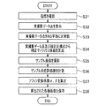
- FIG. 2 shows a flowchart of special image generation processing executed in the special mode.
- the special image generation process of FIG. 2 is started when the operation mode of the electronic endoscope system 1 is switched to the special mode.
- FIG. 3 is a diagram for conceptually explaining the operation of the correction circuit 220D, and shows an RG plane defined by the R axis and the G axis orthogonal to each other.
- the R axis is the axis of the R component (R pixel value)
- the G axis is the axis of the G component (G pixel value).
- pixel data of each pixel in the RGB color space defined by the RGB three primary colors is converted into RG pixel data (two-dimensional made up of two types of color components).
- the pixel data points of each pixel in the RGB color space and the pixel data points plotted in the RG plane are referred to as “pixel corresponding points”.
- FIG. 3 for the sake of clarity, only the pixel corresponding points of some pixels are shown instead of the pixel corresponding points of all the pixels.
- the color component constitutes a color space (including a color plane). Also, hue and saturation are excluded from the “color component”.
- each pixel data (three-dimensional data) in the RGB color space is orthogonally projected onto the RG plane, and a perpendicular drawn from the point in the RGB color space corresponding to each pixel data to the RG plane. Is a pixel corresponding point (two-dimensional data).
- movement which converts the pixel data of each pixel of RGB color space into the pixel data of RG plane (orthographic projection) performed by this process step S12 is performed by the conversion means.
- the correction circuit 220D sets a reference axis in the RG plane necessary for calculating the inflammation intensity of the target disease such as gastritis.
- FIG. 4 is a diagram for assisting the explanation of the reference axis.
- the R component is dominant over the other components (G component and B component) due to the influence of hemoglobin pigment and the like.
- Taste (R component) becomes stronger than other colors (G component and B component).
- the color of the captured image of the living tissue in the body cavity changes depending on the imaging condition that affects the brightness (for example, the degree of hitting of the white light L).
- the shaded portion where the white light L does not reach is black (achromatic color, for example, R, G, B is zero or a value close to zero), and the portion where the white light L strikes strongly and is specularly reflected is White (achromatic color, for example, R, G, B is a value close to 255 or 255).
- the pixel value of the abnormal part image increases as the white light L strikes stronger. Therefore, depending on how the white light L hits, the pixel value may take a value that has no correlation with the intensity of inflammation.
- a normal site in a body cavity where inflammation has not occurred is covered with sufficient mucosa.
- an abnormal site in a body cavity where inflammation occurs is not covered with sufficient mucosa.
- blood vessels and blood fluids leak from the blood vessels as the blood vessels dilate, so that the mucous membrane becomes relatively thin and the color of blood is easily visible.
- the mucous membrane is basically a white tone, but has a slightly yellowish color, and the color (yellow color) reflected on the image changes depending on the shade (thickness of the mucous membrane). Therefore, the density of the mucous membrane is considered to be one of the evaluation criteria for evaluating the intensity of inflammation.
- a straight line passing through (50, 0) and (255, 76) is set as one of the reference axes in the RG plane, and (0, 0) and (255, 192) are set as one of the reference axes.
- the former reference axis is referred to as “hemoglobin change axis AX1”, and the latter reference axis is referred to as “mucosal change axis AX2”.
- the plot shown in FIG. 4 is obtained as a result of analysis of a large number of sample images of living tissue in the body cavity by the inventor.
- Sample images used for analysis are considered to be inflammatory images with the highest symptom level (the most severe inflammatory image example) and inflammatory images with the lowest symptom level (substantially normal or healthy sites). Examples of inflammation images at each stage are included.
- FIG. 4 only a part of the plot obtained as a result of the analysis is shown for the sake of clarity.
- the number of plots actually obtained as a result of the analysis is much larger than the number of plots shown in FIG.
- the R component becomes stronger with respect to other components (G component and B component) as the abnormal site is more intensely inflamed. Therefore, it is a boundary line between a region where the plot is distributed and a region where the plot is not distributed, and is an axis on the boundary line closer to the R axis than the G axis, in the example of FIG. 4, (50, 0) and (255, 76).
- This axis is the hemoglobin change axis AX1.
- On the hemoglobin change axis AX1 a plot corresponding to an inflammatory site having the highest symptom level, taken under various imaging conditions, for example, under different conditions of the white light L, is superimposed.
- the G component (or B component) becomes stronger than the R component as the degree of inflammation is smaller and closer to the normal site. Therefore, it is a boundary line between a region where the plot is distributed and a region where the plot is not distributed, and is an axis on the boundary line closer to the G axis than the R axis, in the example of FIG. 4, (0, 0) and (255, 192). )
- the lesion with the lowest symptom level (the inflammatory site (abnormal site) with the lowest symptom level, which is considered to be a substantially normal site, in other words, a healthy site) Set as a highly correlated axis. This axis is the mucosa changing axis AX2.
- the mucous membrane change axis AX2 has a plot corresponding to an inflammatory site having the lowest symptom level taken under various imaging conditions, for example, under different conditions of the white light L, in other words, a site regarded as a substantially normal site. Are superimposed.
- the inflammatory site with the highest symptom level for the target disease is accompanied by bleeding.
- the inflammatory site with the lowest symptom level is a substantially normal site and is therefore covered with sufficient mucosa. Therefore, the plot in the RG plane shown in FIG. 4 can be understood as being distributed in a region sandwiched between an axis having the highest correlation with blood (hemoglobin pigment) and an axis having the highest correlation with mucous color. .
- the boundary line closer to the R axis is the axis indicating the inflammation site with the highest symptom level, that is, the hemoglobin change axis AX1
- the boundary line closer to the G axis corresponds to the axis indicating the inflammatory site having the lowest symptom level, that is, the mucosa change axis AX2.
- a correction matrix coefficient calculated in a calibration mode (to be described later) is stored in a storage medium such as the memory in the correction circuit 220D and the memory 222.
- the correction circuit 220D performs pixel corresponding points of each pixel in order to suppress variations in score values when the same lesioned part is imaged by different electronic endoscope systems, in other words, individual differences of electronic scopes.
- Pixel data (R, G) is corrected using the correction matrix coefficient.
- amends the pixel corresponding point of each pixel using correction matrix coefficient performed by this process step S14 is performed by a color component correction means.
- the correction circuit 220D shown in FIG. 2 preferably functions as a color component correction unit.
- the scoring circuit 220E calculates the inflammation intensity for the pixel data (R new, G new ) of all the pixels in the current frame corrected in the processing step S14 (correction of pixel data).
- the angle for is calculated. Specifically, in this processing step S15, for each pixel, a line segment L connecting the reference point O ′, which is the intersection of the hemoglobin change axis AX1 and the mucosa change axis AX2, and the pixel corresponding point (R new, G new ). And an angle ⁇ (see FIG. 3) formed by the hemoglobin change axis AX1 is calculated.
- the reference point O ′ is located at the coordinates ( ⁇ 150, ⁇ 75).
- the pixel corresponding point corresponding to the inflamed site changes depending on how the white light L hits
- the pixel corresponding point shifts in the azimuth direction starting from the reference point O ′.
- the angle ⁇ remains constant and the distance from the reference point O ′ changes. This means that the angle ⁇ is a parameter that is substantially unaffected by changes in the brightness of the captured image.
- the scoring circuit 220E causes the angle 255 for all pixels in the current frame so that the value 255 is obtained when the angle ⁇ is zero and the value is zero when the angle ⁇ is ⁇ MAX.
- ⁇ is normalized. Note that ⁇ MAX is equal to the angle formed by the hemoglobin change axis AX1 and the mucosa change axis AX2. As a result, information on the inflammation intensity falling within the range of 0 to 255, that is, 8-bit information is obtained.
- the scoring circuit 220E uses the average value obtained by averaging the inflammation intensity of all the pixels in the current frame, or the integrated value of the inflammation intensity of all the pixels as a temporary inflammation evaluation value for the entire captured image. Calculated.
- movement which calculates the inflammation evaluation value performed by this process step S17 is performed by an acquisition means.
- the memory in the correction circuit 220D or the storage medium such as the memory 222 stores affine transformation coefficients ⁇ and ⁇ calculated in the calibration mode described later.
- processing step S17 (calculation of inflammation evaluation value) is performed.
- the temporary inflammation evaluation value calculated in this way is affine transformed using the affine transformation coefficients ⁇ and ⁇ to become a definite value, as shown in the following equation.
- display data of the inflammation evaluation value converted into a definite value (display data example: Score: OO) is generated.
- sample inflammation evaluation values are calculated for a plurality of sample images. Of each calculated value, the highest sample inflammation evaluation value is converted into a first specific value, for example, the maximum value of the inflammation evaluation value, and the lowest sample inflammation evaluation value is lower than the first specific value.
- affine transformation coefficients ⁇ and ⁇ are conceivable.
- a coefficient set for converting the average value of all the calculated sample inflammation evaluation values into a specific value, and a coefficient set for minimizing the sum of errors between each sample inflammation evaluation value and a predetermined target value are affine.
- Conversion coefficients ⁇ and ⁇ may be used.
- movement which carries out the affine transformation of the inflammation evaluation value using this affine transformation coefficient (alpha) and (beta) performed by this process step S18 is performed by the evaluation result correction
- the scoring circuit 220E shown in FIG. 2 preferably functions as an evaluation result correction unit.
- the mapping circuit 220F causes the display color of each pixel of the current frame on the color map image to be the value of the inflammation intensity obtained in S17 (calculation of inflammation evaluation value) based on the above table. Depending on the color.
- mapping circuit 220F converts the color data of each pixel of the current frame into the display color data determined in the processing step S19 (determining the display color on the color map image). Color map image data composed of pixels displayed in the displayed display color is generated.
- generates color map image data performed by this process step S20 is performed by the acquisition means.
- the mapping circuit 220F shown in FIG. 2 preferably functions as a color map image acquisition unit.
- the output circuit 220C causes a normal color image based on the normal color image data input from the process circuit 220B, and the color map image generated in the processing step S20 (color map image data generation).
- the former image data (normal color image data) and the latter image data (color map image data) are added using the ratio of overlaying the color map image based on the data as a coefficient.
- the coefficient setting can be appropriately changed by a user operation. For example, when a normal color image is desired to be displayed darker, the color image data coefficient is set higher. When a color map image is desired to be displayed darker, the color map image data coefficient is set higher.
- the output circuit 220C generates display data of an overlay image of a normal color image and a color map image based on the image data added in processing step S21 (overlay processing) in FIG.
- a masking process for masking the peripheral area is performed, and screen data for monitor display is generated by superimposing an inflammation evaluation value on the mask area generated by the masking process.
- the output circuit 220 ⁇ / b> C converts the generated monitor display screen data into a predetermined video format signal and outputs it to the monitor 300.
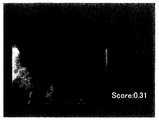
- Fig. 5 shows a screen display example in the special mode.
- a captured image in the body cavity an overlay image in which a normal image and a color map image are displayed in an overlay manner
- an image display area A screen with a mask around is displayed.
- an inflammation evaluation value (score) is displayed in the mask area.
- the display form of the captured image in the special mode is not limited to an overlay display of a normal color image and a color map image.
- both the normal color image and the color map image may be displayed with the same size, or one of the normal color image and the color map image is displayed as the main image and the other is smaller than the main image. It may be displayed as an image.
- the operation executed by the output circuit 220C to display the image including the inflammation evaluation value and the color map image on the display screen of the monitor 300 is performed by the display means.
- the output circuit 220C shown in FIG. 2 preferably functions as a display unit.
- a highly accurate inflammation evaluation value or color map image can be obtained by performing simple calculation processing without performing nonlinear calculation processing such as tone enhancement processing or complicated color space conversion processing. Is obtained. That is, the hardware resources necessary for calculating the inflammation evaluation value and generating the color map image are greatly reduced.
- the inflammation evaluation value and the color map image do not substantially vary depending on the imaging condition that affects the brightness of the captured image in the body cavity, for example, the degree of irradiation light irradiation. Therefore, the surgeon can identify, for example, a lesioned part with high accuracy, and can perform a more objective and accurate diagnosis.
- FIG. 6 shows a flowchart of the calibration process executed in the calibration mode.
- the calibration process of FIG. 6 is executed at the time of factory shipment or maintenance, for example, and is started when the operation mode of the electronic endoscope system 1 is switched to the calibration mode.
- preparation work by the worker is performed prior to the execution of the calibration process. Specifically, the operator adjusts the white balance of the electronic endoscope system 1 using a white balance dedicated jig, a white plate having the same specifications as the white balance dedicated jig, a gray card, or the like.
- the operator sets the electronic endoscope system 1 on the calibration jig and on the terminal (PC) for the electronic endoscope system connected to the processor 200, Start the calibration software.
- the worker adjusts the brightness of the captured image by the electronic scope 100.
- the operator manually adjusts the opening of the aperture 212 so that the brightness value of the captured image when the subject for brightness adjustment is captured falls within the target brightness value.
- the luminance value of the captured image can be confirmed on calibration software.
- FIG. 7 shows a schematic configuration of the calibration jig 400 according to the present embodiment.
- the calibration jig 400 includes a measurement box 402.
- an introduction port 402a is formed in the measurement box 402.
- the worker inserts the distal end portion of the electronic scope 100 to a predetermined position in the measurement box 402 through the introduction port 402a.
- the introduction port 402a is substantially blocked. Thereby, external light does not enter into the measurement box 402, and the measurement box 402 functions as a dark box. Since calibration is not affected by external light, the accuracy of calibration is improved.
- 404B are set.
- the index (specific color sample) is a color index imitating a specific color related to the target disease, and can be appropriately exchanged according to the target disease.
- the index (specific color sample) 404A is an index imitating the first color that is the color of the living tissue when the symptom level is the highest for the target disease, for example.
- the index 404A is a plate-like member coated with a color corresponding to a predetermined point (correction target point PT1 described later) on the hemoglobin change axis AX1 in the RG plane.
- the index (specific color sample) 404B is, for example, an index imitating the second color that is the color of a healthy living tissue.
- the index 404B is a plate-like member to which a color corresponding to a predetermined point (correction target point PT2 described later) on the mucous membrane change axis AX2 in the RG plane is applied.
- the actual photographing data points P D1 and P D2 are calculated as the actual measurement values of the indices 404A and 404B from the captured image data photographed in the processing step S31 (index photographing) by the calibration software.
- the Illustratively, the average value of the pixels (for example, 200 ⁇ 200 pixels) in the central region of the image of the index 404A extracted from the captured image is calculated as the actual captured data point P D1 , and the index 404B extracted from the captured image
- An average value of pixels (for example, 200 ⁇ 200 pixels) in the central region of the image is calculated as the actual shooting data point PD2 .
- correction matrix coefficients are calculated by the calibration software.
- the correction matrix coefficients are measured values, that is, actual shooting data points P D1 (R D1 , G D1 ), actual shooting data points P D2 (R D2 , G D2 ) are set to target values, In other words, the correction target point P T1 (R T1 , G T1 ) and the correction target point P T2 (R T2 , G T2 ) are coefficients to be corrected.
- the corrected target point P T1 (R T1 , G T1 ) corresponds to the color on the hemoglobin change axis AX1 imitated by the index 404A, and the corrected target point P T2 (R T2 , G T2 ) This corresponds to the color on the mucous membrane change axis AX2.
- the operation for calculating the correction matrix coefficient executed in this processing step S34 is performed by the color component correction coefficient calculation means.
- a software module in a terminal (PC) for an electronic endoscope system connected to the processor 200 serves as a color component correction coefficient calculation unit.
- sample image is taken using the electronic scope 1.
- the sample image is illustratively a photographed image of an index (indicator 404A or 404B or an index different from these) set in the measurement box 402, or means different from the calibration jig 400 Or an image of an index photographed using.
- the affine transformation coefficients ⁇ and ⁇ are calculated using the sample inflammation evaluation value of each sample image calculated in the processing step S36 (calculation of the sample inflammation evaluation value).
- any method listed in the processing step S18 (determining the inflammation evaluation value) in FIG. 2 may be adopted, and other methods are adopted. Also good.
- the operation of calculating the affine transformation coefficients ⁇ and ⁇ executed in this processing step S37 is performed by the evaluation result correction coefficient calculating means.
- a software module in a terminal (PC) for an electronic endoscope system connected to the processor 200 serves as an evaluation result correction coefficient calculation unit.
- the correction target is limited, specifically, a specific color related to the target disease is set as the correction target, so that it remains in the color data used when the target disease is evaluated.
- Errors mainly errors due to variations due to individual differences in the optical parts of the electronic scope 100, can be satisfactorily removed. Thereby, evaluation accuracy improves.
- the color components to be color-corrected using the correction matrix coefficients are only m types of color components converted from n types of color components, and (nm) types of colors. Contains no ingredients. Since (nm) types of color components are not used for inflammation evaluation values, there is no need for color correction. As described above, since color correction is performed only for the color component used for the inflammation evaluation value, the correction matrix coefficient can be accurately created based on the index.
- the electronic endoscope system according to the embodiment brings about the following effects and solutions in the technical field.
- the electronic endoscope system is a diagnostic aid for early detection of inflammatory diseases.
- the configuration of the embodiment it is possible to display the degree of inflammation on the screen or to emphasize the image of the region where the inflammation has occurred so that the surgeon can find mild inflammation that is difficult to visually recognize.
- mild inflammation is difficult to distinguish from a normal part, the effects brought about by the configuration of the embodiment with respect to the evaluation of mild inflammation become significant.
- an objective evaluation value can be provided to the surgeon as an evaluation of the degree of inflammation, so that a difference in diagnosis between the surgeons can be reduced.
- the merit of providing an objective evaluation value according to the configuration of the present embodiment to an inexperienced surgeon is great.
- the configuration of the embodiment it is possible to display the inflamed part as an image in real time by reducing the load of image processing. Therefore, diagnostic accuracy can be improved.
- the color map image (image showing the degree of inflammation) and the normal image are displayed side by side or combined and displayed without delay. can do. Therefore, it is possible to display a color map image without extending the examination time, and as a result, it is possible to avoid an increase in patient burden.
- the observation target part in the embodiment is, for example, a respiratory organ, a digestive organ, or the like.
- the respiratory organ or the like is, for example, the lung or the ENT.
- Examples of digestive organs include the large intestine, the small intestine, the stomach, the duodenum, and the uterus.
- the electronic endoscope system according to the embodiment is considered to be more effective when the observation target is the large intestine. Specifically, this is due to the following reasons.
- the inflammation evaluation value according to the embodiment is effective as a criterion for evaluation of inflammatory bowel disease (IBD) represented by ulcerative colitis. Since a treatment method for ulcerative colitis has not been established, the use of the electronic endoscope system having the configuration of the present embodiment has an extremely great effect of early detection and suppression of progression.
- IBD inflammatory bowel disease
- the large intestine is a long and slender organ compared to the stomach and the like, and the obtained image has a depth and becomes darker at the back. According to the configuration of the embodiment, it is possible to suppress the fluctuation of the evaluation value due to the change in brightness in the image. Therefore, when the electronic endoscope system according to the present embodiment is applied to observation of the large intestine, the effect of the embodiment becomes remarkable. That is, the electronic endoscope system according to the embodiment is preferably an electronic endoscope system for respiratory organs or an electronic endoscope system for digestive organs, and more preferably an electronic endoscope system for large intestine.
- mild inflammation is generally difficult to diagnose
- the configuration of the embodiment for example, by displaying the result of evaluating the degree of inflammation on the screen, it is possible to prevent the operator from overlooking the mild inflammation.
- the judgment criteria are not clear, and this is a factor that increases individual differences among surgeons.
- an objective evaluation value can be provided to the surgeon, so that variations in diagnosis due to individual differences can be reduced.
- the above-described configuration of the embodiment can be applied not only to the degree of inflammation but also to the evaluation value of various lesions accompanied by cancer, polyps, and other color changes. In these cases, the same advantages as described above can be applied. Can have an effect. That is, the evaluation value of the embodiment is preferably an evaluation value of a lesion accompanied by a color change, and includes an evaluation value of at least one of inflammation level, cancer, and polyp.
- Embodiments of the present invention are not limited to those described above, and various modifications are possible within the scope of the technical idea of the present invention.
- the embodiment of the present application also includes an embodiment that is exemplarily specified in the specification or a combination of obvious embodiments and the like as appropriate.
- the operator selects the first color, for example, the color of the living tissue when the symptom level is the highest for the target disease, as one of the indices, and one of the other indices
- the second color for example, the color of the living tissue when healthy is selected. Therefore, in the above embodiment, the first color and the second color in the color space, that is, the color closer to the correction target color is calibrated with higher accuracy. In other words, in the color space, a color that is far from the correction target, for example, a color that cannot be inflamed, such as light blue, has a lower calibration accuracy.
- the operator may select an index set on the calibration jig in the calibration mode that corresponds to the symptom level to be scored with high accuracy using the electronic endoscope system 1. For example, when it is desired to improve the scoring accuracy for mild inflammation, the operator may select an index imitating the color of living tissue when mild inflammation occurs.
- the system controller 202 receives an operation for specifying a symptom level by an operator via a connected peripheral device (such as a keyboard), an index corresponding to the specified symptom level is displayed on the display screen of the monitor 300. Or can be notified by voice playback. Thereby, the surgeon can reliably select an appropriate index from a plurality of indices.
- the calibration process may be performed using three or more indices.
- each process such as correction using a correction matrix coefficient, correction using an affine transformation coefficient, and calculation of an inflammation evaluation value is all performed on the RG plane. Only part processing may be performed in another color space such as YUV.
- image processing with a change in color according to user settings for example, TE (Tone Enhancement) processing may be performed in the process circuit 220B.
- TE Te Enhancement
- the appropriate values of the various coefficients of the correction matrix coefficient and the affine transformation coefficient are different between the case where the image processing accompanied by the color change is performed and the case where the image processing is not performed. Therefore, various coefficients suitable for performing the TE process and various coefficients suitable for not performing the TE process may be stored in the storage medium such as the memory and the memory 222 in the correction circuit 220D.
- the TE process is performed, correction using the former various coefficients is performed, and when the TE process is not performed, correction using the latter various coefficients is performed.
- pixel data in the RGB color space is converted into pixel data on the RG plane, and the inflammation evaluation value is calculated using the R component and G component included in each converted pixel data.
- a target disease stomach constriction
- evaluation values for colorectal tumors and the like can also be calculated.
- a plurality of types of correction matrix coefficients and affine transformation coefficients corresponding to various target diseases may be stored in the memory 222 of the processor 200 and the memory in the correction circuit 220D.
- the evaluation value that is stable is calculated for each target disease.
- the light source used for the electronic endoscope system various types of light sources can be used.
- the type of the light source is limited (for example, a laser is excluded as the light source type).
- the optimum values of the correction matrix coefficient and the affine transformation coefficient vary depending on the spectral characteristics of the light source used. Therefore, for example, when the processor 200 includes a plurality of types of light sources, or when a plurality of types of external light sources are switched and used, the correction matrix coefficient and the away conversion coefficient for each type of light source are stored in the memory 222 of the processor 200 or the correction. It may be stored in a memory in the circuit 220D. Thereby, the dispersion
- the angle ⁇ formed by the line segment L connecting the reference point O ′ and the pixel corresponding point of the target pixel and the hemoglobin change axis AX1 is calculated, and inflammation evaluation is performed based on the calculated angle ⁇ .
- the present invention is not limited to this.
- an angle formed by the line segment L and the mucous membrane change axis AX2 may be calculated, and the inflammation evaluation value may be calculated based on the calculated angle.
- the smaller the calculated angle the stronger the G component with respect to the R component, indicating that the severity of the inflammatory site is lower, and the larger the calculated angle, the stronger the R component with respect to the G component. Indicates a high degree. Therefore, in processing step S16 FIG. 2 (normalization), value when calculating the angle is zero becomes zero, to a value 255 when calculating the angle is theta MAX, normalizing inflammation evaluation value To do.
- the intersection of the hemoglobin change axis AX1 and the mucosa change axis AX2 is set as the reference point O ′ in order to suppress the influence of the brightness of the captured image on the inflammation evaluation value as much as possible.
- the invention is not limited to this.
- the origin (0, 0) of the RG plane located on the mucous membrane change axis AX2 may be set as the reference point O ′.
- the minimum required reference axis is sufficient (mucosal change axis AX2), the load of the special image generation process in FIG. 2 is reduced, and the processing speed is improved.
- the light source unit including the lamp power igniter 206, the lamp 208, the condenser lens 210, the diaphragm 212, the motor 214, and the like is provided integrally with the processor.
- the light source unit is separate from the processor. It may be provided as a body device.
- a CMOS image sensor may be used as the solid-state imaging device 108 instead of the CCD image sensor.
- a CMOS image sensor in general, an image tends to be darker as a whole as compared with a CCD image sensor. Therefore, the advantageous effect that the fluctuation of the evaluation value due to the brightness of the image by the configuration of the above-described embodiment can be suppressed becomes more prominent in a situation where a CMOS image sensor is used as the solid-state imaging device.
- the resolution of the image is preferably 1 million pixels or more, more preferably 2 million pixels, and even more preferably 8 million pixels or more.
- the processing load for performing the above-described evaluation value calculation for all pixels increases.
- the processing load of evaluation value calculation can be suppressed, and therefore, the advantageous effect of the configuration of the embodiment is remarkably exhibited in a situation where a high-definition image is processed.
- all the pixels in the image are processed.
- extremely high luminance pixels and extremely low luminance pixels may be excluded from the processing targets.
- the accuracy of the evaluation value can be improved by setting only the pixels determined to have the luminance within a predetermined reference luminance range as the evaluation value calculation target.
- Electronic Endoscope System 100 Electronic Scope 102 LCB 104 Light distribution lens 106 Objective lens 108 Solid-state imaging device 112 Driver signal processing circuit 114 Memory 200 Processor 202 System controller 204 Timing controller 206 Lamp power source igniter 208 Lamp 210 Condensing lens 212 Aperture 214 Motor 216 Driver 218 Operation panel 220 Signal processing circuit 220A Pre-processing circuit 220B Process circuit 220C Output circuit 220D Correction circuit 220E Scoring circuit 220F Mapping circuit 222 Memory
Landscapes
- Health & Medical Sciences (AREA)
- Life Sciences & Earth Sciences (AREA)
- Engineering & Computer Science (AREA)
- Surgery (AREA)
- Physics & Mathematics (AREA)
- Medical Informatics (AREA)
- General Health & Medical Sciences (AREA)
- Pathology (AREA)
- Heart & Thoracic Surgery (AREA)
- Biophysics (AREA)
- Molecular Biology (AREA)
- Animal Behavior & Ethology (AREA)
- Biomedical Technology (AREA)
- Public Health (AREA)
- Veterinary Medicine (AREA)
- Nuclear Medicine, Radiotherapy & Molecular Imaging (AREA)
- Radiology & Medical Imaging (AREA)
- Optics & Photonics (AREA)
- Signal Processing (AREA)
- General Physics & Mathematics (AREA)
- Theoretical Computer Science (AREA)
- Multimedia (AREA)
- Artificial Intelligence (AREA)
- Evolutionary Computation (AREA)
- Quality & Reliability (AREA)
- Computer Vision & Pattern Recognition (AREA)
- Endoscopes (AREA)
- Image Processing (AREA)
Abstract
電子内視鏡用プロセッサは、n(n≧3)種類の色成分よりなる体腔内のカラー画像を構成する各画素データをn種類よりも少ないm(m≧2)種類の色成分よりなる画素データに変換する変換手段と、変換されたm種類の色成分よりなる画素データを所定の色成分補正係数を用いて補正する色成分補正手段と、補正されたm種類の色成分よりなる画素データに基づいて対象疾患に関する評価結果を取得する取得手段とを備える構成とする。
Description
本発明は、電子内視鏡用プロセッサ及び電子内視鏡システムに関する。
人体内部の観察や治療に電子内視鏡システムが使用されている。電子内視鏡システムを使用した内視鏡観察では、病変部と正常な部位とを正確に識別する必要がある。病変部は、例えば血管新生などにより、正常な部位とは色調が異なる場合が多い。特許文献1には、内視鏡画像の色情報に基づいて病変部である可能性が高い部位を特定し、特定された部位を強調表示することによって内視鏡画像診断を支援する機能を備えた電子内視鏡システムが記載されている。
上記のように内視鏡画像の色情報に基づいて病変部等を正確に特定するためには、少なくとも病変部等の特定に用いる色領域において正確な色情報を有する内視鏡画像を取得する必要がある。従来の電子内視鏡システムには、内視鏡画像の色情報を補正する機能として、ホワイトバランス補正機能が備えられている。
ホワイトバランス補正は、無彩色軸上の一点(例えば白色)のみで色補正を行うものであるため、有彩色の誤差を補正することができない。そのため、色情報を補正する機能としてホワイトバランス補正機能のみを備えた従来の電子内視鏡システムでは、色情報の誤差が大きく、このことが病変部等を識別する精度を低いものにしていた。
本発明は上記の事情に鑑みてなされたものであり、その目的とするところは、内視鏡画像の色成分に基づいて病変部等を識別する場合の識別精度を向上させるのに好適な電子内視鏡用プロセッサ及び電子内視鏡システムを提供することである。
本発明の一実施形態に係る電子内視鏡用プロセッサは、n(n≧3)種類の色成分よりなる体腔内の生体組織のカラー画像を構成する各画素データをn種類よりも少ないm(m≧2)種類の色成分よりなる画素データに変換する変換手段と、変換されたm種類の色成分よりなる画素データを所定の色成分補正係数を用いて補正する色成分補正手段と、補正されたm種類の色成分よりなる画素データに基づいて対象疾患に関する評価結果を取得する取得手段とを備える。
また、本発明の一実施形態に係る電子内視鏡用プロセッサは、n(n≧3)種類の色成分よりなる体腔内の生体組織のカラー画像を構成する各画素データをn種類よりも少ないm(m≧2)種類の色成分よりなる画素データに変換する変換手段と、変換されたm種類の色成分よりなる画素データに基づいて対象疾患に関する評価結果を取得する取得手段と、取得された評価結果を所定の評価結果補正係数を用いて補正する評価結果補正手段とを備える。
すなわち、本発明の一実施形態に係る電子内視鏡用プロセッサは、
n(n≧3)種類の色成分よりなる体腔内の生体組織のカラー画像を構成する各画素データをn種類よりも少ないm(m≧2)種類の色成分よりなる画素データに変換する変換手段と、
変換された前記m種類の色成分よりなる画素データに基づいて対象疾患に関する評価結果を取得する取得手段と、
前記変換手段により変換された前記m種類の色成分よりなる画素データを所定の色成分補正係数を用いて補正する色成分補正手段、及び、前記取得手段で取得された評価結果を所定の評価結果補正係数を用いて補正する評価結果補正手段の少なくとも一方の補正手段と、
を備えることが好ましい。
n(n≧3)種類の色成分よりなる体腔内の生体組織のカラー画像を構成する各画素データをn種類よりも少ないm(m≧2)種類の色成分よりなる画素データに変換する変換手段と、
変換された前記m種類の色成分よりなる画素データに基づいて対象疾患に関する評価結果を取得する取得手段と、
前記変換手段により変換された前記m種類の色成分よりなる画素データを所定の色成分補正係数を用いて補正する色成分補正手段、及び、前記取得手段で取得された評価結果を所定の評価結果補正係数を用いて補正する評価結果補正手段の少なくとも一方の補正手段と、
を備えることが好ましい。
この構成において、一実施形態によれば、電子内視鏡用プロセッサは、m種類の色成分よりなる画素データを所定の色成分補正係数を用いて補正する色成分補正手段を更に備えることが好ましい。また、この場合、一実施形態によれば、取得手段は、色成分補正係数によって補正されたm種類の色成分よりなる画素データに基づいて対象疾患に関する評価結果を取得することが好ましい。
また、本発明の一実施形態によれば、色成分補正係数は、例えば、m種類の色成分よりなる画素データを補正する所定の補正マトリックス係数であることが好ましい。
また、本発明の一実施形態によれば、評価結果補正係数は、例えば、評価結果をアフィン変換するアフィン変換係数であることが好ましい。
また、本発明の一実施形態によれば、前記色成分補正手段が行う色補正の対象とする色成分は、前記n種類の色成分のうち、前記m種類の色成分であり、(n-m)種類の色成分を含まない、ことが好ましい。
また、本発明の一実施形態によれば、前記取得手段は、前記m種類の色成分より定義される色空間内において、所定の基準点から見た前記対象疾患に関する基準方向を設定しており、前記カラー画像の各画素について、前記色空間における前記変換された画素データに対応する画素対応点の前記基準点から見た方向の、前記基準方向からのずれの程度に基づいて、前記対象疾患に関する評価結果を取得する、ことが好ましい。
また、本発明の一実施形態によれば、取得手段は、m種類の色成分より定義される色平面内において、所定の基準点を通る、対象疾患に関する基準軸を設定しており、各画素について、該基準点と該画素データに対応する画素対応点とを結ぶ線分と、該基準軸と、がなす角度に基づいて、該対象疾患に関する評価結果を取得することが好ましい。
また、本発明の一実施形態によれば、前記基準軸を第1基準軸というとき、
前記取得手段は、前記色平面内において、前記基準点を通る、前記対象疾患が無い健常部位に関する第2基準軸を設定しており、
前記第1基準軸と前記第2基準軸の交差角度を最大角度として、前記角度θを正規化して評価値を算出する、ことが好ましい。
前記取得手段は、前記色平面内において、前記基準点を通る、前記対象疾患が無い健常部位に関する第2基準軸を設定しており、
前記第1基準軸と前記第2基準軸の交差角度を最大角度として、前記角度θを正規化して評価値を算出する、ことが好ましい。
また、本発明の一実施形態によれば、変換手段は、n種類の色成分より定義される色空間における各画素データを色平面に正射影することが好ましい。
また、本発明の一実施形態によれば、基準軸は、例えば、対象疾患について症状レベルの最も高い炎症部位を示す軸であることが好ましい。いいかえると、前記基準軸は、前記対象疾患について症状レベルが高くなるほど変換された前記画素対応点が収束する軸であることが好ましい。
また、本発明の一実施形態によれば、色平面は、例えば、R成分の軸とG成分の軸を含む平面であることが好ましい。
また、本発明の一実施形態によれば、前記変換された画素データのm種類の色成分のいずれも、波長帯域が互いに異なるように設定された色成分である、ことが好ましい。
また、本発明の一実施形態によれば、評価結果は、例えば、対象疾患に関する評価を示す値と、該対象疾患に関する評価を示すカラー画像の少なくとも一方を含むことが好ましい。
また、本発明の一実施形態に係る電子内視鏡システムは、上記の電子内視鏡用プロセッサと、対象疾患と関連する少なくとも2以上の指標を撮影することによって得られる少なくとも2種類以上の実撮影データに基づいて色成分補正係数を算出する色成分補正係数算出手段を備える。
また、本発明の一実施形態に係る電子内視鏡システムは、上記の電子内視鏡用プロセッサと、複数の指標の各々を撮影することによって各指標の評価結果を取得し、取得された各指標の評価結果を用いて評価結果補正係数を算出する評価結果補正係数算出手段を備える。
また、本発明の一実施形態に係る電子内視鏡システムは、上記の電子内視鏡用プロセッサと、該電子内視鏡用プロセッサにて求められた評価結果を表示画面に表示するように構成された表示装置と、を備える。
また、本発明の一実施形態によれば、前記電子内視鏡用プロセッサは、前記カラー画像の各画素の色を、各画素の前記評価結果として算出される評価値に応じた色に変換してカラーマップ画像を取得する取得手段と、前記カラーマップ画像を前記表示装置の表示画面に表示させる表示手段と、を備え、前記表示装置、例えばモニタは、前記評価値の代表値と前記カラーマップ画像を同時に表示するように構成されている、ことが好ましい。
また、本発明の一実施形態によれば、色相及び彩度は、色成分から除かれる。
上述の電子内視鏡用プロセッサ及び電子内視鏡システムによれば、内視鏡画像の色成分に基づいて病変部等を識別する場合の識別精度を向上させることができる。
以下、本発明の実施形態について図面を参照しながら説明する。以下においては、本発明の一実施形態として電子内視鏡システムを例に取り説明する。
図1は、本発明の一実施形態に係る電子内視鏡システム1の構成を示すブロック図である。図1に示されるように、電子内視鏡システム1は、医療用に特化されたシステムであり、電子スコープ100、プロセッサ200及びモニタ300を備えている。
プロセッサ200は、システムコントローラ202及びタイミングコントローラ204を備えている。システムコントローラ202は、メモリ222に記憶された各種プログラムを実行し、電子内視鏡システム1全体を統合的に制御する。また、システムコントローラ202は、操作パネル218に接続されている。システムコントローラ202は、操作パネル218より入力される術者からの指示に応じて、電子内視鏡システム1の各動作及び各動作のためのパラメータを変更する。術者による入力指示には、例えば電子内視鏡システム1の動作モードの切替指示がある。本実施形態では、動作モードとして、通常モード、特殊モード及びキャリブレーションモードがある。タイミングコントローラ204は、各部の動作のタイミングを調整するクロックパルスを電子内視鏡システム1内の各回路に出力する。
ランプ208は、ランプ電源イグナイタ206による始動後、白色光Lを射出する。ランプ208は、例えば、キセノンランプ、ハロゲンランプ、水銀ランプ、メタルハライドランプ等の高輝度ランプである。ランプ208より射出された白色光Lは、集光レンズ210によって集光されつつ絞り212を介して適正な光量に制限される。なお、ランプ208は、LD(Laser Diode)やLED(Light Emitting Diode)等の半導体発光素子に置き換えてもよい。半導体発光素子に関しては、他の光源と比較して、低消費電力、発熱量が小さい等の特徴があるため、消費電力や発熱量を抑えつつ明るい画像を取得できるというメリットがある。明るい画像が取得できることは、後述する炎症評価値の精度を向上させることにつながる。半導体発光素子は、プロセッサ200に限らず、電子スコープ100に内蔵されてもよい。一例として、半導体発光素子は、電子スコープ100の先端部内に備えられてもよい。
絞り212には、図示省略されたアームやギヤ等の伝達機構を介してモータ214が機械的に連結している。モータ214は例えばDCモータであり、ドライバ216のドライブ制御下で駆動する。絞り212は、モニタ300の表示画面に表示される映像を適正な明るさにするため、モータ214により動作され開度が変えられる。ランプ208より照射された白色光Lの光量は、絞り212の開度に応じて制限される。適正とされる映像の明るさの基準は、術者による操作パネル218の輝度調節操作に応じて設定変更される。なお、ドライバ216を制御して輝度調整を行う調光回路は周知の回路であり、本明細書においては省略することとする。
絞り212を通過した白色光Lは、LCB(Light Carrying Bundle)102の入射端面に集光されてLCB102内に入射される。入射端面よりLCB102内に入射された白色光Lは、LCB102内を伝播する。
LCB102内を伝播した白色光Lは、電子スコープ100の先端に配置されたLCB102の射出端面より射出され、配光レンズ104を介して生体組織を照射する。白色光Lにより照射された生体組織からの戻り光は、対物レンズ106を介して固体撮像素子108の受光面上で光学像を結ぶ。
固体撮像素子108は、補色市松フィルタを搭載した単板式カラーCCD(Charge-Coupled Device)イメージセンサである。固体撮像素子108は、受光面上の各画素で結像した光学像を光量に応じた電荷として蓄積して、イエローYe、シアンCy、グリーンG、マゼンタMgの画素データを生成して出力する。なお、固体撮像素子108は、CCDイメージセンサに限らず、CMOS(Complementary Meta1 Oxide Semiconductor)イメージセンサやその他の種類の撮像装置に置き換えられてもよい。
また、固体撮像素子108は、原色系フィルタ(ベイヤ配列フィルタ)を搭載したものであってもよい。原色系(RGB)フィルタは、補色系フィルタと比較して発色性が良い。そのため、原色系フィルタを搭載した撮像素子によるRGB形式の画像信号を後述の炎症評価値の算出に使用すると、評価精度を向上させることができる。また、原色系フィルタを使用することにより、炎症評価値計算の処理において信号の変換を行う必要がない。そのため、炎症評価値計算の処理負荷を抑えることが可能となる。
電子スコープ100の接続部内には、ドライバ信号処理回路112が備えられている。ドライバ信号処理回路112には、白色光Lにより照射された生体組織を撮像した各画素の画素データが固体撮像素子108よりフレーム周期で入力される。ドライバ信号処理回路112は、固体撮像素子108より入力される画素データをプロセッサ200の信号処理回路220に出力する。なお、以降の説明において「フレーム」は「フィールド」に置き替えてもよい。本実施形態において、フレーム周期、フィールド周期はそれぞれ、1/30秒、1/60秒である。
ドライバ信号処理回路112はまた、メモリ114にアクセスして電子スコープ100の固有情報を読み出す。メモリ114に記録される電子スコープ100の固有情報には、例えば、固体撮像素子108の画素数や感度、動作可能なフレームレート、型番等が含まれる。ドライバ信号処理回路112は、メモリ114より読み出された固有情報をシステムコントローラ202に出力する。
システムコントローラ202は、電子スコープ100の固有情報に基づいて各種演算を行い、制御信号を生成する。システムコントローラ202は、生成された制御信号を用いて、プロセッサ200に接続されている電子スコープに適した処理がなされるようにプロセッサ200内の各種回路の動作やタイミングを制御する。
タイミングコントローラ204は、システムコントローラ202によるタイミング制御に従って、ドライバ信号処理回路112にクロックパルスを供給する。ドライバ信号処理回路112は、タイミングコントローラ204から供給されるクロックパルスに従って、固体撮像素子108をプロセッサ200側で処理される映像のフレームレートに同期したタイミングで駆動制御する。
[通常モード時の動作]
通常モード時のプロセッサ200での信号処理動作を説明する。
通常モード時のプロセッサ200での信号処理動作を説明する。
プロセッサ200に備えられる信号処理回路220は、プリプロセス回路220A、プロセス回路220B、出力回路220C、補正回路220D、スコアリング回路220E、及びマッピング回路220Fを有している。
プリプロセス回路220Aは、ドライバ信号処理回路112よりフレーム周期で入力されるRAW形式の画素データにデモザイク処理を施してRGB形式の画素データに変換し、カラーマトリックス処理、ホワイトバランス調整、Hueゲイン調整等を施してプロセス回路220Bに出力する。
プロセス回路220Bは、プリプロセス回路220Aより入力される画素データにエンハンス処理、カンマ補正等を施して通常のカラー画像データを生成し、出力回路220Cに出力する。
出力回路220Cは、プロセス回路220Bより入力されるカラー画像データに対してY/C分離、色差補正等の処理を施して所定のビデオフォーマット信号に変換する。変換されたビデオフォーマット信号は、モニタ300に出力される。これにより、生体組織の通常のカラー画像がモニタ300の表示画面に表示される。
[特殊モード時の動作]
次に、特殊モード時のプロセッサ200での信号処理動作を説明する。図2に、特殊モード時に実行される特殊画像生成処理のフローチャートを示す。図2の特殊画像生成処理は、電子内視鏡システム1の動作モードが特殊モードに切り替えられた時点で開始される。
次に、特殊モード時のプロセッサ200での信号処理動作を説明する。図2に、特殊モード時に実行される特殊画像生成処理のフローチャートを示す。図2の特殊画像生成処理は、電子内視鏡システム1の動作モードが特殊モードに切り替えられた時点で開始される。
[図2のS11(現フレームの画素データの入力)]
本処理ステップS11では、現フレームの各画素の画素データがプリプロセス回路220Aに入力される。各画素の画素データは、プリプロセス回路220Aによる信号処理後、プロセス回路220B及び補正回路220Dに入力される。
本処理ステップS11では、現フレームの各画素の画素データがプリプロセス回路220Aに入力される。各画素の画素データは、プリプロセス回路220Aによる信号処理後、プロセス回路220B及び補正回路220Dに入力される。
[図2のS12(RG平面への正射影)]
図3に、補正回路220Dの動作を概念的に説明するための図であって、互いに直交するR軸とG軸とによって定義されるRG平面を示す。なお、R軸は、R成分(Rの画素値)の軸であり、G軸は、G成分(Gの画素値)の軸である。
図3に、補正回路220Dの動作を概念的に説明するための図であって、互いに直交するR軸とG軸とによって定義されるRG平面を示す。なお、R軸は、R成分(Rの画素値)の軸であり、G軸は、G成分(Gの画素値)の軸である。
本処理ステップS12では、RGB3原色で定義されるRGB色空間の各画素の画素データ(3種類の色成分よりなる三次元の画素データ)がRGの画素データ(2種類の色成分よりなる二次元の画素データ)に変換される。概念的には、図3に示されるように、RGB色空間の各画素の画素データが、R、Gの画素値に応じてRG平面内(より詳細には、R=0~255、G=0~255の値を取るRG平面内の区画)にプロットされる。以下、説明の便宜上、RGB色空間の各画素の画素データの点及びRG平面内にプロットされた画素データの点を「画素対応点」と記す。なお、図3においては、図面を明瞭化する便宜上、全ての画素の画素対応点を示すのではなく一部の画素の画素対応点のみ示している。
なお、本発明において、色成分は、色空間(色平面も含む。)を構成するものである。また、色相及び彩度は、「色成分」から除かれる。
このように、本処理ステップS12では、RGB色空間の各画素データ(三次元データ)がRG平面に正射影され、各画素データに対応するRGB色空間内の点からRG平面に下された垂線の足が各画素対応点(二次元データ)となる。
なお、本処理ステップS12にて実行される、RGB色空間の各画素の画素データをRG平面の画素データに変換(正射影)する動作は、変換手段により行われる。一実施形態によれば、図2に示す補正回路220Dが変換手段の機能を担うことが好ましい。
[図2のS13(基準軸の設定)]
本処理ステップS13では、補正回路220Dにより、胃炎等の対象疾患の炎症強度を計算するために必要なRG平面内の基準軸が設定される。図4に、基準軸の説明を補助する図を示す。
本処理ステップS13では、補正回路220Dにより、胃炎等の対象疾患の炎症強度を計算するために必要なRG平面内の基準軸が設定される。図4に、基準軸の説明を補助する図を示す。
撮影対象となる患者の体腔内の生体組織は、ヘモグロビン色素等の影響によりR成分が他の成分(G成分及びB成分)に対して支配的であり、典型的には、炎症が強いほど赤味(R成分)が他の色味(G成分及びB成分)に対して強くなる。しかし、体腔内の生体組織の撮影画像は、明るさに影響する撮影条件(例えば白色光Lの当たり具合)に応じて色味が変化する。例示的には、白色光Lの届かない陰影部分は黒(無彩色であり、例えば、R、G、Bがゼロ又はゼロに近い値)となり、白色光Lが強く当たって正反射する部分は白(無彩色であり、例えば、R、G、Bが255又は255に近い値)となる。すなわち、炎症が起こっている同じ異常部位を撮影した場合であっても、白色光Lが強く当たるほどその異常部位画像の画素値が大きくなる。そのため、白色光Lの当たり具合によっては、画素値が炎症の強さと相関の無い値を取ることがある。
一般に、炎症が起こっていない体腔内の正常部位は十分な粘膜で覆われている。これに対し、炎症が起こっている体腔内の異常部位は十分な粘膜で覆われていない。具体的には、血管が拡張すると共に血管から血液・体液が漏出するため、相対的に粘膜が薄くなり血液の色が目に映り易くなる。粘膜は、基本的には白基調ではあるが、色味としては若干黄味がかっており、その濃淡(粘膜の厚み)によって画像上に写る色味(黄色の色味)が変化する。従って、粘膜の濃淡も炎症の強さを評価する評価用判定基準の一つになるものと考えられる。
そこで、本処理ステップS13では、図4に示されるように、RG平面内において、(50,0)及び(255,76)を通る直線が基準軸の1つとして設定されると共に、(0,0)及び(255,192)を通る直線が基準軸の1つとして設定される。説明の便宜上、前者の基準軸を「ヘモグロビン変化軸AX1」と記し、後者の基準軸を「粘膜変化軸AX2」と記す。
図4に示されるプロットは、本発明者が体腔内の生体組織の多数のサンプル画像を解析した結果得たものである。解析に用いられるサンプル画像には、症状レベルの最も高い炎症画像例(最も重症なレベルの炎症画像例)や、症状レベルの最も低い炎症画像例(実質的に正常部位あるいは健常部位であるとみなされる画像例)など、各段階の炎症画像例が含まれる。なお、図4の例では、図面を明瞭化する便宜上、解析の結果得られたプロットを一部だけ示している。解析の結果実際に得られたプロットは、図4に示されるプロットの数よりも遥かに多い。
上述したように、炎症が強い異常部位ほどR成分が他の成分(G成分及びB成分)に対して強くなる。そのため、プロットが分布する領域と分布しない領域との境界線であって、G軸よりもR軸に近い方の境界線上の軸、図4の例では、(50,0)及び(255,76)を通る境界線上の軸が、症状レベルの最も高い病変部(症状レベルの最も高い炎症部位(異常部位))と相関の高い軸として設定される。この軸がヘモグロビン変化軸AX1である。ヘモグロビン変化軸AX1には、様々な撮影条件、例えば白色光Lの当たり具合が種々異なる条件で撮影された症状レベルの最も高い炎症部位に対応するプロットが重畳される。
一方、炎症の程度が小さく正常部位に近いほどG成分(又はB成分)がR成分に対して強くなる。そのため、プロットが分布する領域と分布しない領域との境界線であって、R軸よりもG軸に近い方の境界線上の軸、図4の例では、(0,0)及び(255,192)を通る境界線上の軸が、症状レベルの最も低い病変部(症状レベルの最も低い炎症部位(異常部位)であって、実質的に正常部位、いいかえると健常部位であるとみなされるもの)と相関の高い軸として設定される。この軸が粘膜変化軸AX2である。粘膜変化軸AX2には、様々な撮影条件、例えば白色光Lの当たり具合が種々異なる条件で撮影された症状レベルの最も低い炎症部位、いいかえると実質的に正常部位とみなされる部位に対応するプロットが重畳される。
補足すると、対象疾患について症状レベルの最も高い炎症部位は、出血を伴う。一方、症状レベルの最も低い炎症部位は、実質正常部位であるから、十分な粘膜で覆われている。そのため、図4に示されるRG平面内のプロットは、血液(ヘモグロビン色素)と最も相関の高い軸と、粘膜の色味と最も相関の高い軸に挟まれた領域内に分布すると捉えることができる。そのため、プロットが分布する領域と分布しない領域との境界線のうち、R軸に近い(R成分が強い)方の境界線が、症状レベルの最も高い炎症部位を示す軸、すなわちヘモグロビン変化軸AX1に相当し、G軸に近い(G成分が強い)方の境界線が、症状レベルの最も低い炎症部位を示す軸、すなわち粘膜変化軸AX2に相当する。
[図2のS14(画素データの補正)]
補正回路220D内のメモリやメモリ222等の記憶媒体には、後述のキャリブレーションモード時に算出された補正マトリックス係数が保存されている。本処理ステップS14では、同一の病変部を異なる電子内視鏡システムで撮影したときのスコア値のばらつき、言い換えると、電子スコープの個体差を抑えるため、補正回路220Dにより、各画素の画素対応点てある画素データ(R,G)が補正マトリックス係数を用いて補正される。
補正回路220D内のメモリやメモリ222等の記憶媒体には、後述のキャリブレーションモード時に算出された補正マトリックス係数が保存されている。本処理ステップS14では、同一の病変部を異なる電子内視鏡システムで撮影したときのスコア値のばらつき、言い換えると、電子スコープの個体差を抑えるため、補正回路220Dにより、各画素の画素対応点てある画素データ(R,G)が補正マトリックス係数を用いて補正される。
・補正マトリックス例

Rnew :補正後の画素データ(R成分)
Gnew :補正後の画素データ(G成分)
M00~M11:補正マトリックス係数
R :補正前の画素データ(R成分)
G :補正前の画素データ(G成分)
Rnew :補正後の画素データ(R成分)
Gnew :補正後の画素データ(G成分)
M00~M11:補正マトリックス係数
R :補正前の画素データ(R成分)
G :補正前の画素データ(G成分)
なお、本処理ステップS14にて実行される、各画素の画素対応点を補正マトリックス係数を用いて補正する動作は、色成分補正手段により行われる。一実施形態によれば、図2に示す補正回路220Dが色成分補正手段の機能を担うことが好ましい。
[図2のS15(角度の算出)]
本処理ステップS15では、スコアリング回路220Eにより、処理ステップS14(画素データの補正)にて補正された、現フレームの全ての画素の画素データ(Rnew,Gnew)について、炎症強度を計算するための角度が算出される。具体的には、本処理ステップS15では、各画素について、ヘモグロビン変化軸AX1と粘膜変化軸AX2との交点である基準点O’と画素対応点(Rnew,Gnew)とを結ぶ線分Lと、ヘモグロビン変化軸AX1とがなす角度θ(図3参照)が算出される。なお、基準点O’は、座標(-150,-75)に位置する。
本処理ステップS15では、スコアリング回路220Eにより、処理ステップS14(画素データの補正)にて補正された、現フレームの全ての画素の画素データ(Rnew,Gnew)について、炎症強度を計算するための角度が算出される。具体的には、本処理ステップS15では、各画素について、ヘモグロビン変化軸AX1と粘膜変化軸AX2との交点である基準点O’と画素対応点(Rnew,Gnew)とを結ぶ線分Lと、ヘモグロビン変化軸AX1とがなす角度θ(図3参照)が算出される。なお、基準点O’は、座標(-150,-75)に位置する。
[図2のS16(正規化処理)]
体腔内の生体組織の撮影画像の明るさが白色光Lの当たり具合によって変化すると、撮影画像の色味は、個人差、撮影箇所、炎症の状態等の影響があるものの、RG平面内において、概ね、症状レベルの最も高い炎症部位ではヘモグロビン変化軸AX1上に沿って変化し、症状レベルの最も低い炎症部位、すなわち健常部位では粘膜変化軸AX2上に沿って変化する。また、中間の症状レベルの炎症部位の撮影画像の色味も同じ傾向で変化するものと推定される。すなわち、炎症部位に対応する画素対応点は、白色光Lの当たり具合によって変化すると、基準点O’を起点とした方位角方向にシフトする。言い換えると、炎症部位に対応する画素対応点は、白色光Lの当たり具合によって変化すると、角度θが一定のまま移動して基準点O’との距離が変わる。これは、角度θが撮影画像の明るさの変化に実質的に影響を受けないパラメータであることを意味する。
体腔内の生体組織の撮影画像の明るさが白色光Lの当たり具合によって変化すると、撮影画像の色味は、個人差、撮影箇所、炎症の状態等の影響があるものの、RG平面内において、概ね、症状レベルの最も高い炎症部位ではヘモグロビン変化軸AX1上に沿って変化し、症状レベルの最も低い炎症部位、すなわち健常部位では粘膜変化軸AX2上に沿って変化する。また、中間の症状レベルの炎症部位の撮影画像の色味も同じ傾向で変化するものと推定される。すなわち、炎症部位に対応する画素対応点は、白色光Lの当たり具合によって変化すると、基準点O’を起点とした方位角方向にシフトする。言い換えると、炎症部位に対応する画素対応点は、白色光Lの当たり具合によって変化すると、角度θが一定のまま移動して基準点O’との距離が変わる。これは、角度θが撮影画像の明るさの変化に実質的に影響を受けないパラメータであることを意味する。
角度θが小さいほどR成分がG成分に対して強くなり、炎症部位の症状レベルが高いことを示す。また、角度θが大きいほどG成分がR成分に対して強くなり、炎症部位の症状レベルが低いことを示す。
そこで、本処理ステップS16では、スコアリング回路220Eにより、角度θがゼロであるときに値255となり、角度θがθMAXであるときに値ゼロとなるように、現フレームの全ての画素について角度θが正規化される。なお、θMAXは、ヘモグロビン変化軸AX1と粘膜変化軸AX2とがなす角度と等しい。これにより、0~255の範囲に収まる炎症強度の情報、すなわち8bitの情報が得られる。
[図2のS17(炎症評価値の計算)]
本処理ステップS17では、スコアリング回路220Eにより、現フレームの全ての画素の炎症強度を平均化した平均値,又は全ての画素の炎症強度の積算値が撮影画像全体の暫定的な炎症評価値として計算される。
本処理ステップS17では、スコアリング回路220Eにより、現フレームの全ての画素の炎症強度を平均化した平均値,又は全ての画素の炎症強度の積算値が撮影画像全体の暫定的な炎症評価値として計算される。
なお、本処理ステップS17にて実行される、炎症評価値を計算する動作は、取得手段により行われる。一実施形態によれば、図2に示すスコアリング回路220Eが取得手段の機能を担うことが好ましい。
[図2のS18(炎症評価値の確定)]
補正回路220D内のメモリあるいはメモリ222等の記憶媒体には、後述のキャリブレーションモード時に算出されたアフィン変換係数α、βが保存されている。本処理ステップS18では、同一の病変部を異なる電子内視鏡システムで撮影したときのスコア値のばらつき、言い換えると、電子スコープの個体差を抑えるため、処理ステップS17(炎症評価値の計算)にて計算された暫定的な炎症評価値が、次式に示されるように、アフィン変換係数α及びβを用いてアフィン変換されて確定値となる。また、本処理ステップS18では、確定値に変換された炎症評価値の表示データ(表示データ例:Score:○○)が生成される。
補正回路220D内のメモリあるいはメモリ222等の記憶媒体には、後述のキャリブレーションモード時に算出されたアフィン変換係数α、βが保存されている。本処理ステップS18では、同一の病変部を異なる電子内視鏡システムで撮影したときのスコア値のばらつき、言い換えると、電子スコープの個体差を抑えるため、処理ステップS17(炎症評価値の計算)にて計算された暫定的な炎症評価値が、次式に示されるように、アフィン変換係数α及びβを用いてアフィン変換されて確定値となる。また、本処理ステップS18では、確定値に変換された炎症評価値の表示データ(表示データ例:Score:○○)が生成される。
・アフィン変換例
H = αH’十 β
H :炎症評価値(確定値)
H’:炎症評価値(暫定値)
H = αH’十 β
H :炎症評価値(確定値)
H’:炎症評価値(暫定値)
アフィン変換係数α及びβの算出方法を例示する。アフィン変換係数α及びβを算出する際、複数のサンプル画像について暫定的な炎症評価値(以下、説明の便宜上「サンプル炎症評価値」と記す。)が計算される。計算された各値のうち、最も高いサンプル炎症評価値を第一の特定値、例えば炎症評価値の最大値に変換し、かつ最も低いサンプル炎症評価値を第一の特定値よりも低い第二の特定値、例えば炎症評価値の最小値に変換する係数セット(傾きα、切片β)がアフィン変換係数として求められる。
なお、アフィン変換係数α、βには、種々のものが考えられる。例示的には、計算された全てのサンプル炎症評価値の平均値を特定値に変換する係数セットや、各サンプル炎症評価値と所定の目標値との誤差の総和を最も小さくする係数セットをアフィン変換係数α、βとしてもよい。
なお、本処理ステップS18にて実行される、炎症評価値をアフィン変換係数α及びβを用いてアフィン変換する動作は、評価結果補正手段により行われる。一実施形態によれば、図2に示すスコアリング回路220Eが評価結果補正手段の機能を担うことが好ましい。
[図2のS19(カラーマップ画像上での表示色の決定)]
本実施形態では、炎症強度に応じた表示色で撮影画像をモザイク化したカラーマップ画像を表示することができる。カラーマップ画像を表示可能とするため、炎症強度の値と所定の表示色とを対応付けたテーブルがスコアリング回路220Eの所定の記憶領域に記憶されている。このテーブルでは、例えば、値5刻みで異なる表示色が対応付けられている。例示的には、炎症強度の値が0~5の範囲では黄色が対応付けられており、該値が5増える毎に色相環での色の並び順に従って異なる表示色が対応付けられており、該値が250~255の範囲では赤色が対応付けられている。
本実施形態では、炎症強度に応じた表示色で撮影画像をモザイク化したカラーマップ画像を表示することができる。カラーマップ画像を表示可能とするため、炎症強度の値と所定の表示色とを対応付けたテーブルがスコアリング回路220Eの所定の記憶領域に記憶されている。このテーブルでは、例えば、値5刻みで異なる表示色が対応付けられている。例示的には、炎症強度の値が0~5の範囲では黄色が対応付けられており、該値が5増える毎に色相環での色の並び順に従って異なる表示色が対応付けられており、該値が250~255の範囲では赤色が対応付けられている。
本処理ステップS19では、マッピング回路220Fにより、現フレームの各画素の、カラーマップ画像上での表示色が、上記テーブルに基づいて、S17(炎症評価値の計算)にて得た炎症強度の値に応じた色に決定される。
[図2のS20(カラーマップ画像データの生成)]
本処理ステップS20では、マッピング回路220Fにより、現フレームの各画素の色データが、処理ステップS19(カラーマップ画像上での表示色の決定)にて決定された表示色のデータに変換され、変換された表示色で表示される画素よりなるカラーマップ画像データが生成される。
本処理ステップS20では、マッピング回路220Fにより、現フレームの各画素の色データが、処理ステップS19(カラーマップ画像上での表示色の決定)にて決定された表示色のデータに変換され、変換された表示色で表示される画素よりなるカラーマップ画像データが生成される。
なお、本処理ステップS20にて実行される、カラーマップ画像データを生成する動作は、取得手段により行われる。一実施形態によれば、図2に示すマッピング回路220Fがカラーマップ画像の取得手段の機能を担うことが好ましい。
[図2のS21(オーバレイ処理)]
本処理ステップS21では、出力回路220Cにより、プロセス回路220Bより入力される通常のカラー画像データに基づく通常のカラー画像と、処理ステップS20(カラーマップ画像データの生成)にて生成されたカラーマップ画像データに基づくカラーマップ画像とをオーバレイさせる割合を係数として、前者の画像データ(通常のカラー画像データ)と後者の画像データ(カラーマップ画像データ)とが加算される。
本処理ステップS21では、出力回路220Cにより、プロセス回路220Bより入力される通常のカラー画像データに基づく通常のカラー画像と、処理ステップS20(カラーマップ画像データの生成)にて生成されたカラーマップ画像データに基づくカラーマップ画像とをオーバレイさせる割合を係数として、前者の画像データ(通常のカラー画像データ)と後者の画像データ(カラーマップ画像データ)とが加算される。
なお、係数の設定は、ユーザ操作により適宜設定変更することが可能である。例えば、通常のカラー画像の方を濃く表示したい場合は、カラー画像データの係数が高く設定され、カラーマップ画像の方を濃く表示したい場合は、カラーマップ画像データの係数が高く設定される。
[図2のS22(終了判定)]
本処理ステップS22では、電子内視鏡システム1の動作モードが特殊モードとは別のモードに切り替えられたか否かが判定される。別のモードに切り替えられていないと判定される場合(S22:NO)、図2の特殊画像生成処理は、処理ステップS11(現フレームの画素データの入力)に戻る。一方、別のモードに切り替えられたと判定される場合(S22:YES)、図2の特殊画像生成処理は終了する。
本処理ステップS22では、電子内視鏡システム1の動作モードが特殊モードとは別のモードに切り替えられたか否かが判定される。別のモードに切り替えられていないと判定される場合(S22:NO)、図2の特殊画像生成処理は、処理ステップS11(現フレームの画素データの入力)に戻る。一方、別のモードに切り替えられたと判定される場合(S22:YES)、図2の特殊画像生成処理は終了する。
[画面表示例]
出力回路220Cは、図2の処理ステップS21(オーバレイ処理)にて加算処理された画像データに基づいて通常のカラー画像とカラーマップ画像とのオーバレイ画像の表示データを生成すると共にモニタ300の表示画面の周辺領域(画像表示領域の周囲)をマスクするマスキング処理を行い、更に、マスキング処理により生成されるマスク領域に炎症評価値を重畳した、モニタ表示用の画面データを生成する。出力回路220Cは、生成されたモニタ表示用の画面データを所定のビデオフォーマット信号に変換して、モニタ300に出力する。
出力回路220Cは、図2の処理ステップS21(オーバレイ処理)にて加算処理された画像データに基づいて通常のカラー画像とカラーマップ画像とのオーバレイ画像の表示データを生成すると共にモニタ300の表示画面の周辺領域(画像表示領域の周囲)をマスクするマスキング処理を行い、更に、マスキング処理により生成されるマスク領域に炎症評価値を重畳した、モニタ表示用の画面データを生成する。出力回路220Cは、生成されたモニタ表示用の画面データを所定のビデオフォーマット信号に変換して、モニタ300に出力する。
図5に、特殊モード時の画面表示例を示す。図5に例示されるように、モニタ300の表示画面には、その中央領域に体腔内の撮影画像(通常画像とカラーマップ画像とがオーバレイ表示されたオーバレイ画像)が表示されると共に画像表示領域の周囲がマスキングされた画面が表示される。また、マスク領域には、炎症評価値(スコア)が表示される。
なお、特殊モード時の撮影画像の表示形態は、通常のカラー画像とカラーマップ画像とをオーバレイ表示したものに限らない。例えば、通常のカラー画像とカラーマップ画像を一画面内に並べて表示したり、カラーマップ画像のみを表示したりする表示形態が挙げられる。前者の場合、通常のカラー画像とカラーマップ画像の両方を同一のサイズで表示してもよいし、通常のカラー画像とカラーマップ画像の一方をメイン画像として表示すると共に他方をメイン画像より小さいサブ画像として表示してもよい。
出力回路220Cにより実行される、炎症評価値やカラーマップ画像を含む画像をモニタ300の表示画面に表示させる動作は、表示手段により行われる。一実施形態によれば、図2に示す出力回路220Cが表示手段の機能を担うことが好ましい。
このように、実施形態によれば、トーン強調処理等の非線形な計算処理や複雑な色空間変換処理等を行うことなく単純な計算処理を行うだけで、精度の高い炎症評価値やカラーマップ画像が求まる。すなわち、炎症評価値の計算やカラーマップ画像の生成に必要なハードウェアリソースが大幅に抑えられる。
また、実施形態によれば、体腔内の撮影画像の明るさに影響する撮影条件、例えば照射光の当たり具合等によって炎症評価値やカラーマップ画像が実質的に変動しない。そのため、術者は、例えば病変部等を高い精度で識別することができ、より客観的で正確な診断を行うことが可能となる。
[キャリブレーションモード時の動作]
次に、キャリブレーションモード時の電子内視鏡システム1の動作について説明する。キャリブレーションモード時に実行されるキャリブレーション処理では、対象疾患に関連する特定の色を補正対象としたキャリブレーションが行われる。
次に、キャリブレーションモード時の電子内視鏡システム1の動作について説明する。キャリブレーションモード時に実行されるキャリブレーション処理では、対象疾患に関連する特定の色を補正対象としたキャリブレーションが行われる。
図6に、キャリブレーションモード時に実行されるキャリブレーション処理のフローチャートを示す。図6のキャリブレーション処理は、例えば、工場出荷時やメンテナンス時等のタイミングで実行されるものであり、電子内視鏡システム1の動作モードがキャリブレーションモードに切り替えられた時点で開始される。
なお、キャリブレーション処理の実行に先立ち、作業者による準備作業が行われる。具体的には、作業者は、ホワイトバランス専用治具や、ホワイトバランス専用治具と同じ仕様の白板、グレーカード等を用いて電子内視鏡システム1のホワイトバランスを調整する
作業者は、ホワイトバランスの調整が完了すると、電子内視鏡システム1をキャリブレーション用治具にセットすると共に、プロセッサ200に接続された、電子内視鏡システム用の端末(PC)上で、キャリブレーション用ソフトウェアを起動させる。
作業者は、次いで、電子スコープ100による撮影画像の輝度調整を行う。例示的には、作業者は、輝度調整用の被写体を撮影したときの撮影画像の輝度値が目標輝度値に収まるように、絞り212の開度をマニュアル調整する。なお、撮影画像の輝度値は、キャリブレーション用ソフトウェア上で確認することができる。
図7に、本実施形態に係るキャリブレーション用治具400の概略構成を示す。図7に示されるように、キャリブレーション用治具400は、測定箱402を備えている。測定箱402には、導入口402aが形成されている。
作業者は、電子スコープ100の先端部を導入口402aを介して測定箱402内の所定位置まで挿入する。電子スコープ100の先端部が測定箱402内に挿入されることにより、導入口402aが実質的に塞がれる。これにより、測定箱402内に外光が入らず、測定箱402は暗箱として機能する。キャリブレーション処理時に外光の影響を受けないため、キャリブレーションの精度が向上する。
測定箱402内には、導入口402aと対向する位置、言い換えると、電子スコープ100の先端面(配光レンズや対物レンズ等の配置面)と正対する位置に一対の指標(特定色見本)404A、404Bがセットされている。指標(特定色見本)は、対象疾患に関連する特定の色を模した色指標であり、対象疾患に応じて適宜交換することが可能となっている。
指標(特定色見本)404Aは、例えば、対象疾患について症状レベルが最も高いときの生体組織の色である第一の色を模した指標である。本実施形態において、指標404Aは、RG平面内のヘモグロビン変化軸AX1上の所定点(後述の補正目標点PT1)に対応する色が塗布された板状部材である。
指標(特定色見本)404Bは、例えば、健常である生体組織の色である第二の色を模した指標である。実施形態において、指標404Bは、RG平面内の粘膜変化軸AX2上の所定点(後述の補正目標点PT2)に対応する色が塗布された板状部材である。
[図6のS31(指標の撮影)]
作業者は、モニタ300の表示画面に表示される撮影画像を視認しながら、指標404A及び404Bが電子スコープ1の画角に収まるように、測定箱402内における電子スコープ100の先端部の位置を調整する。本処理ステップS31では、作業者による操作入力に従い、画角内に収められた指標404A及び40Bが電子スコープ100によって撮影され、その撮影画像データがプロセッサ200に入力される。なお、指標404A、404Bは、別々に撮影されてもよい。作業者は、キャリブレーション用治具400を使用することにより、指標404Aと指標404Bを同一の条件で撮影することができる。
作業者は、モニタ300の表示画面に表示される撮影画像を視認しながら、指標404A及び404Bが電子スコープ1の画角に収まるように、測定箱402内における電子スコープ100の先端部の位置を調整する。本処理ステップS31では、作業者による操作入力に従い、画角内に収められた指標404A及び40Bが電子スコープ100によって撮影され、その撮影画像データがプロセッサ200に入力される。なお、指標404A、404Bは、別々に撮影されてもよい。作業者は、キャリブレーション用治具400を使用することにより、指標404Aと指標404Bを同一の条件で撮影することができる。
[図6のS32(実撮影データ点Pの算出)]
作業者による操作入力に従い又は指定枚数(ここでは一枚)の撮影後自動的に、本処理ステップS32の実行が開始される。
作業者による操作入力に従い又は指定枚数(ここでは一枚)の撮影後自動的に、本処理ステップS32の実行が開始される。
本処理ステップS32では、キャリブレーション用ソフトウェアにより、処理ステップS31(指標の撮影)にて撮影された撮影画像データから、指標404A、404Bの実測値として実撮影データ点PD1、PD2が算出される。例示的には、撮影画像から抽出された指標404Aの画像の中央領域の画素(例えば200×200画素)の平均値が実撮影データ点PD1として算出され、撮影画像から抽出された指標404Bの画像の中央領域の画素(例えば200×200画素)の平均値が実撮影データ点PD2として算出される。
[図6のS33(RG平面への実撮影データ点の正射影)]
本処理ステップS33では、キャリブレーション用ソフトウェアにより、RGB色空間の実撮影データ点PD1(RD1,GD1,BD1)、実撮影データ点PD2(RD2,GD2,BD2)が、それぞれ、対象疾患と関連付けられたRG平面に正射影されて、実撮影データ点PD1(RD1,GD1)、実撮影データ点PD2(RD2,GD2)に変換される。
本処理ステップS33では、キャリブレーション用ソフトウェアにより、RGB色空間の実撮影データ点PD1(RD1,GD1,BD1)、実撮影データ点PD2(RD2,GD2,BD2)が、それぞれ、対象疾患と関連付けられたRG平面に正射影されて、実撮影データ点PD1(RD1,GD1)、実撮影データ点PD2(RD2,GD2)に変換される。
[図6のS34(補正マトリックス係数の算出)]
本処理ステップS34では、キャリブレーション用ソフトウェアにより、補正マトリックス係数が算出される。補正マトリックス係数は、次式に示されるように、実測値、すなわち、実撮影データ点PD1(RD1,GD1)、実撮影データ点PD2(RD2,GD2)を、目標値、すなわち補正目標点PT1(RT1,GT1)、補正目標点PT2(RT2,GT2)に補正する係数である。なお、補正目標点PT1(RT1,GT1)は、指標404Aが模す、ヘモグロビン変化軸AX1上の色に対応し、補正目標点PT2(RT2,GT2)は、指標404Bが模す、粘膜変化軸AX2上の色に対応する。
本処理ステップS34では、キャリブレーション用ソフトウェアにより、補正マトリックス係数が算出される。補正マトリックス係数は、次式に示されるように、実測値、すなわち、実撮影データ点PD1(RD1,GD1)、実撮影データ点PD2(RD2,GD2)を、目標値、すなわち補正目標点PT1(RT1,GT1)、補正目標点PT2(RT2,GT2)に補正する係数である。なお、補正目標点PT1(RT1,GT1)は、指標404Aが模す、ヘモグロビン変化軸AX1上の色に対応し、補正目標点PT2(RT2,GT2)は、指標404Bが模す、粘膜変化軸AX2上の色に対応する。
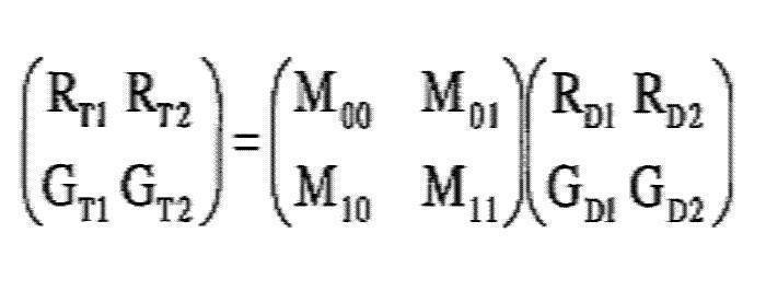
上記の式から、補正マトリックス係数は、次式によって求まることが判る。

なお、本処理ステップS34にて実行される、補正マトリックス係数を算出する動作は、色成分補正係数算出手段により行われる。一実施形態によれば、プロセッサ200に接続された電子内視鏡システム用の端末(PC)におけるソフトウェアモジュールが、色成分補正係数算出手段の機能を担うことが好ましい。
[図6のS35(サンプル画像の撮影)]
本処理ステップS35では、電子スコープ1を用いて複数のサンプル画像が撮影される。サンプル画像は、例示的には、測定箱402内にセットされた指標(指標404Aや404B又はこれらとは別の指標等)の撮影画像であったり、キャリブレーション用治具400とは別の手段を用いて撮影された指標の画像であったりする。
本処理ステップS35では、電子スコープ1を用いて複数のサンプル画像が撮影される。サンプル画像は、例示的には、測定箱402内にセットされた指標(指標404Aや404B又はこれらとは別の指標等)の撮影画像であったり、キャリブレーション用治具400とは別の手段を用いて撮影された指標の画像であったりする。
[図6のS36(サンプル炎症評価値の計算)]
本処理ステップS36では、処理ステップS35(サンプル画像の撮影)にて撮影された各サンプル画像についてサンプル炎症評価値が計算される。
本処理ステップS36では、処理ステップS35(サンプル画像の撮影)にて撮影された各サンプル画像についてサンプル炎症評価値が計算される。
[図6のS37(アフィン変換係数の算出)]
本処理ステップS37では、処理ステップS36(サンプル炎症評価値の計算)にて計算された各サンプル画像のサンプル炎症評価値を用いてアフィン変換係数α、βが算出される。なお、アフィン変換係数α、βの算出方法に関し、図2の処理ステップS18(炎症評価値の確定)にて列記した何れの方法を採用してもよく、また、これら以外の方法を採用してもよい。
本処理ステップS37では、処理ステップS36(サンプル炎症評価値の計算)にて計算された各サンプル画像のサンプル炎症評価値を用いてアフィン変換係数α、βが算出される。なお、アフィン変換係数α、βの算出方法に関し、図2の処理ステップS18(炎症評価値の確定)にて列記した何れの方法を採用してもよく、また、これら以外の方法を採用してもよい。
なお、本処理ステップS37にて実行される、アフィン変換係数α、βを算出する動作は、評価結果補正係数算出手段により行われる。一実施形態によれば、プロセッサ200に接続された電子内視鏡システム用の端末(PC)におけるソフトウェアモジュールが、評価結果補正係数算出手段の機能を担うことが好ましい。
[図6のS38(係数の保存)]
本処理ステップS38では、処理ステップS34(補正マトリックス係数の算出)にて算出された補正マトリックス係数、及び処理ステップS37(アフィン変換係数の算出)にて算出されたアフィン変換係数α、βがプロセッサ200の補正回路220D内のメモリあるいはメモリ222等の記憶媒体に保存される。これにより、図6に示されるキャリプレーション処理が完了する。
本処理ステップS38では、処理ステップS34(補正マトリックス係数の算出)にて算出された補正マトリックス係数、及び処理ステップS37(アフィン変換係数の算出)にて算出されたアフィン変換係数α、βがプロセッサ200の補正回路220D内のメモリあるいはメモリ222等の記憶媒体に保存される。これにより、図6に示されるキャリプレーション処理が完了する。
各電子内視鏡システムに対してキャリブレーション処理を実行することにより、対象疾患に関連する指標を各電子内視鏡システムで撮影したときに略同じ評価結果、即ち、同じ炎症評価値や同じカラーマップ画像が得られる。そのため、対象疾患を各電子内視鏡システムで実際に撮影した場合にも、評価結果のばらつきが抑えられることが判る。
すなわち、実施形態によれば、補正対象を限定する、具体的には、対象疾患に関連する特定の色を補正対象とすることにより、対象疾患の評価を行う際に用いられる色データに残存する誤差、主に電子スコープ100の光学部品の個体差によるばらつきによる誤差が良好に除去される。これにより、評価精度が向上する。
また、別の実施形態によれば、補正マトリックス係数を用いて行う色補正する色成分は、n種類の色成分から変換されたm種類の色成分のみであり、(n-m)種類の色成分を含まない。(n-m)種類の色成分については、炎症評価値に用いられないので、色補正をする必要がない。このように、炎症評価値に用いる色成分のみに限定して色補正をするので、補正マトリックス係数は、指標に基づいて精度よく作成することができる。
なお、補正マトリックス係数による補正とアフィン変換係数による補正の両方の実施は必須ではない。一方の補正を実施することにより、対象疾患のある生体組織を各電子内視鏡システムで撮影したときの評価結果のばらつきが抑えられる効果が得られる。
また、実施形態に係る電子内視鏡システムは、当技術分野における次のような効果及び課題の解決をもたらすものである。
第1に、実施形態に係る電子内視鏡システムは、炎症性疾患を早期に発見するための診断補助となるということである。
第2に、実施形態の構成によれば、視認し難い軽度炎症を術者が発見できるように、炎症程度を画面表示する、又は、炎症が生じている領域の画像を強調することができる。特に、軽度炎症は正常部との判別が難しいため、軽度炎症の評価に関して実施形態の構成によりもたらされる効果が顕著となる。
第3に、実施形態の構成によれば、炎症度の評価として客観的な評価値を術者に提供することができるため、術者間の診断差を低減することができる。特に、経験の浅い術者に対して本実施形態の構成による客観的な評価値を提供できるメリットは大きい。
第4に、実施形態の構成によれば、画像処理の負荷が軽減されることにより、炎症部を画像としてリアルタイムに表示することができる。そのため、診断精度を向上させることができる。
第5に、実施形態の構成によれば、評価値計算の処理負荷が軽減されるため、遅滞なくカラーマップ画像(炎症度を示した画像)と通常画像とを並べて、又は、合成して表示することができる。そのため、検査時間の延長を伴うことなくカラーマップ画像を表示することが可能となり、ひいては、患者負担が増すことを回避することが可能となる。
実施形態における観察の対象部位は、例えば、呼吸器等、消化器等である。呼吸器等は、例えば、肺、耳鼻咽喉である。消化器等は、例えば、大腸、小腸、胃、十二指腸、子宮等である。実施形態に係る電子内視鏡システムは、観察対象が大腸である場合に効果がより顕著になると考えられる。これは、具体的には、次のような理由による。
大腸には炎症を基準として評価できる病があり、炎症している箇所を発見するメリットが他の器官と比較して大きいということである。特に、潰瘍性大腸炎に代表される炎症性腸疾患(IBD)の評価用判定基準として、実施形態による炎症評価値は有効である。潰瘍性大腸炎は治療法が確立されていないため、本実施形態の構成の電子内視鏡システムの使用により早期に発見して進行を抑える効果は非常に大きい。
大腸は、胃等と比較して細長い器官であり、得られる画像は奥行きがあり、奥ほど暗くなる。実施形態の構成によれば、画像内の明るさの変化に起因する評価値の変動を抑えることができる。従って、本実施形態に係る電子内視鏡システムを大腸の観察に適用すると、実施形態による効果が顕著となる。すなわち、実施形態に係る電子内視鏡システムは、呼吸器用電子内視鏡システム又は消化器用電子内視鏡システムであることが好ましく、大腸用電子内視鏡システムであることがより好ましい。
また、軽度の炎症は一般に診断が難しいが、実施形態の構成によれば、例えば、炎症度を評価した結果を画面に表示することで、術者が軽度炎症を見逃すことを回避することができる。特に、軽度の炎症に関しては、その判断基準は明瞭なものではないため、術者間の個人差を大きくする要因となっている。この点に関しても、実施形態の構成によれば、客観的な評価値を術者に提供できるため、個人差による診断のばらつきを低減することができる。
なお、実施形態の上記構成は、炎症度のみでなく、ガン、ポリープその他の色変化を伴う各種病変の評価値の算出に適用することができ、それらの場合においても、上述と同様の有利な効果をもたらすことができる。つまり、施形態の評価値は、色変化を伴う病変の評価値であることが好ましく、炎症度、ガン、ポリープの少なくとも何れかの評価値を含む。
以上が本発明の例示的な実施形態の説明である。本発明の実施形態は、上記に説明したものに限定されず、本発明の技術的思想の範囲において様々な変形が可能である。例えば明細書中に例示的に明示される実施形態等又は自明な実施形態等を適宜組み合わせた内容も本願の実施形態に含まれる。
上記の実施形態では、作業者により、指標の1つとして、第一の色、例えば対象疾患について症状レベルが最も高いときの生体組織の色、を持つものが選択され、他の指標の1つとして、第二の色、例えば健常であるときの生体組織の色を持つものが選択されている。そのため、上記の実施形態では、色空間内において第一の色や第二の色、すなわち補正対象の色に距離が近い色ほど高い精度でキャリブレーションされている。言い換えると、色空間内において、補正対象から距離が遠い色、例えば水色のような、炎症ではあり得ない色ほどキャリブレーションの精度が低い。
従って、作業者は、キャリブレーションモード時にキャリブレーション用治具にセットする指標について、電子内視鏡システム1を用いて特に高い精度でスコアリングしたい症状レベルに対応するものを選択するとよい。例えば、軽度炎症に対するスコアリング精度を向上させたい場合、作業者は、指標として、軽度の炎症が起こったときの生体組織の色を模したものを選択するとよい。
なお、指標が細分化されて用意されるほど、術者がその中から適切な指標を選択することが難しい。そこで、システムコントローラ202は、接続された周辺機器(キーボード等)を介して、作業者による症状レベルを指定する操作を受け付けると、指定された症状レベルに対応する指標をモニタ300の表示画面に表示したり音声再生で通知したりすることができる。これにより、術者は、複数の指標の中から適切な指標を確実に選択することができる。
また、キャリブレーション処理を行うには、最低2つの指標が必要となる。言い換えると、3つ以上の指標を用いてキャリブレーション処理を行ってもよい。
また、上記の実施形態では、補正マトリックス係数による補正、アフィン変換係数による補正及び炎症評価値の計算等の各処理が全てRG平面上で行われているが、例えば補正マトリックス係数による補正など、一部の処理だけがYUV等の別の色空間上で行われてもよい。
また、ユーザの設定に応じて色の変化を伴う画像処理、例えばTE(Tone Enhancement)処理がプロセス回路220Bにて行われてもよい。色の変化を伴う画像処理を行う場合と、行わない場合とでは、補正マトリックス係数、アフィン変換係数の各種係数の適正値が異なる。そのため、補正回路220D内のメモリやメモリ222等の記憶媒体には、TE処理を行う場合に適した各種係数と、TE処理を行わない場合に適した各種係数が保存されていてもよい。TE処理を行う場合は、前者の各種係数を用いた補正が行われ、TE処理を行わない場合は、後者の各種係数を用いた補正が行われる。
また、上記の実施形態では、RGB色空間の画素データがRG平面の画素データに変換され、変換された各画素データに含まれるR成分とG成分を用いて炎症評価値が計算されているが、別の実施形態では、RGB色空間に代えて、CIE 1976 L*a*b*色空間、CIE LCh色空間、CIE 1976 L*u*v*色空間、HSB色空間、sRGB色空間、CMK色空間、CMYK色空間、CMYG色空間等の他の色空間(n(n≧3)種類の色成分より定義される色空間)の画素データをこれよりも低次の色空間(m(n>m≧2)種類の色成分より定義される色空間)の画素データに変換したものを用いることにより、それぞれの色空間に対応する、上記の実施形態とは別の対象疾患(胃の委縮や大腸腫瘍等)に関する評価値を計算することもできる。この場合、上記の実施形態とは異なる指標及び目標点を用いて補正マトリックス係数やアフィン変換係数が算出される。
プロセッサ200のメモリ222や補正回路220D内のメモリには、各種対象疾患に対応する複数種類の補正マトリックス係数及びアフィン変換係数が保存されてもよい。診断対象の疾患に応じて補正マトリックス係数及びアフィン変換係数が切り替わることにより、それぞれの対象疾患で安定した(個体差によるばらつきの少ない)評価値の計算が行われる。
電子内視鏡システム1に使用される光源としては、様々なタイプの光源を用いることができる。他方、電子内視鏡システム1の観察目的等に依存して、光源のタイプを限定的なものとする形態もあり得る(例えば、光源のタイプとしてレーザを除く等)。ここで、補正マトリックス係数及びアフィン変換係数は、使用光源の分光特性によって最適値が変わる。従って、例えば、プロセッサ200が複数種類の光源を備える場合、又は複数種類の外部光源を切り替えて使用する場合には、光源の種類毎の補正マトリックス係数及びアワイン変換係数がプロセッサ200のメモリ222や補正回路220D内のメモリに保存されていてもよい。これにより、使用光源の分光特性による炎症評価値等のばらつきが抑えられる。
また、上記の実施形態では、基準点O’と注目画素の画素対応点とを結ぶ線分Lと、ヘモグロビン変化軸AX1とがなす角度θを算出し、算出された角度θに基づいて炎症評価値を計算しているが、本発明はこれに限らない。例えば、線分Lと粘膜変化軸AX2とがなす角度を算出し、算出された角度に基づいて炎症評価値を計算してもよい。この場合、算出角度が小さいほどG成分がR成分に対して強くなり、炎症部位の重症度が低いことを示し、算出角度が大きいほどR成分がG成分に対して強くなり、炎症部位の重症度が高いことを示す。そのため、図2の処理ステップS16(正規化処理)では、算出角度がゼロであるときに値がゼロとなり、算出角度がθMAXであるときに値255となるように、炎症評価値を正規化する。
また、上記の実施形態では、撮影画像の明るさによる炎症評価値への影響を極力抑えるため、ヘモグロビン変化軸AX1と粘膜変化軸AX2との交点が基準点O’として設定されているが、本発明はこれに限らない。例えば、粘膜変化軸AX2上に位置するRG平面の原点(0,0)が基準点O’として設定されてもよい。この場合、最低限必要な基準軸が一軸(粘膜変化軸AX2)で足りるため、図2の特殊画像生成処理の負荷が軽くなり、処理速度が向上する。
また、上記の実施形態では、ランプ電源イグナイタ206、ランプ208、集光レンズ210、絞り212、モータ214等を含む光源部が、プロセッサと一体に設けられているが、光源部はプロセッサとは別体の装置として設けられていてもよい。
上記の実施形態において説明した通り、固体撮像素子108としてCCDイメージセンサに代え、CMOSイメージセンサが用いられてもよい。CMOSイメージセンサの場合、一般に、CCDイメージセンサと比較して画像が全体的に暗くなる傾向にある。従って、上記の実施形態の構成による、画像の明るさによる評価値の変動を抑えることができるという有利な効果は、固体撮像素子としてCMOSイメージセンサが用いられ状況においてより顕著に表れる。
診断を精度よく行うためには高精細な画像を得ることが好ましい。従って、診断の精度をより向上させる観点では、画像の解像度は、100万画素以上であることが好ましく、200万画素であることがより好ましく、800万画素以上であることが更に好ましい。画像の解像度が高くなるほど全画素について上述の評価値計算を行うための処理負荷が重くなる。しかし、上記の実施形態の構成によれば、評価値計算の処理負荷を抑えることができるため、高精細な画像を処理する状況において実施形態の構成による有利な効果が顕著に表れる。
また、上記の実施形態では、画像中の全ての画素を処理の対象としているが、例えば、極めて高輝度の画素及び極めて低輝度の画素等は、処理の対象から除外してもよい。具体的には、例えば、予め定められた基準輝度範囲の輝度をもつと判定された画素のみを評価値算出の対象とすることによって評価値の精度を向上させることができる。
1 電子内視鏡システム
100 電子スコープ
102 LCB
104 配光レンズ
106 対物レンズ
108 固体撮像素子
112 ドライバ信号処理回路
114 メモリ
200 プロセッサ
202 システムコントローラ
204 タイミングコントローラ
206 ランプ電源イグナイタ
208 ランプ
210 集光レンズ
212 絞り
214 モータ
216 ドライバ
218 操作パネル
220 信号処理回路
220A プリプロセス回路
220B プロセス回路
220C 出力回路
220D 補正回路
220E スコアリング回路
220F マッピング回路
222 メモリ
100 電子スコープ
102 LCB
104 配光レンズ
106 対物レンズ
108 固体撮像素子
112 ドライバ信号処理回路
114 メモリ
200 プロセッサ
202 システムコントローラ
204 タイミングコントローラ
206 ランプ電源イグナイタ
208 ランプ
210 集光レンズ
212 絞り
214 モータ
216 ドライバ
218 操作パネル
220 信号処理回路
220A プリプロセス回路
220B プロセス回路
220C 出力回路
220D 補正回路
220E スコアリング回路
220F マッピング回路
222 メモリ
Claims (16)
- nを3以上の自然数とし、mを2以上の自然数とし、n種類の色成分よりなる体腔内の生体組織のカラー画像を構成する各画素データをn種類よりも少ないm種類の色成分よりなる画素データに変換する変換手段と、
変換されたm種類の色成分よりなる画素データを所定の色成分補正係数を用いて補正する色成分補正手段と、
補正されたm種類の色成分よりなる画素データに基づいて対象疾患に関する評価結果を取得する取得手段と、
を備える、電子内視鏡用プロセッサ。 - nを3以上の自然数とし、mを2以上の自然数とし、n種類の色成分よりなる体腔内の生体組織のカラー画像を構成する各画素データをn種類よりも少ないm種類の色成分よりなる画素データに変換する変換手段と、
変換されたm種類の色成分よりなる画素データに基づいて対象疾患に関する評価結果を取得する取得手段と、
取得された評価結果を所定の評価結果補正係数を用いて補正する評価結果補正手段と、
を備える、電子内視鏡用プロセッサ。 - 前記m種類の色成分よりなる変換された画素データを所定の色成分補正係数を用いて補正する色成分補正手段を更に備え、
前記取得手段は、前記色成分補正係数によって補正されたm種類の色成分よりなる画素データに基づいて対象疾患に関する評価結果を取得する、
請求項2に記載の電子内視鏡用プロセッサ。 - 前記色成分補正手段が行う色補正の対象とする色成分は、前記n種類の色成分のうち、前記m種類の色成分であり、(n-m)種類の色成分を含まない、請求項1または請求項3に記載の電子内視鏡用プロセッサ。
- 前記色成分補正係数は、前記m種類の色成分よりなる画素データを補正する所定の補正マトリックス係数である、
請求項1、請求項3、または請求項4に記載の電子内視鏡用プロセッサ。 - 前記評価結果補正係数は、前記評価結果をアフィン変換するアフィン変換係数である、
請求項2、請求項3、又は、請求項3を引用する請求項4に記載の電子内視鏡用プロセッサ。 - 前記取得手段は、前記m種類の色成分より定義される色空間内において、所定の基準点から見た前記対象疾患に関する基準方向を設定しており、前記カラー画像の各画素について、前記色空間における前記変換された画素データに対応する画素対応点の前記基準点から見た方向の、前記基準方向からのずれの程度に基づいて、前記対象疾患に関する評価結果を取得する、
請求項1から請求項6の何れか一項に記載の電子内視鏡用プロセッサ。 - 前記取得手段は、前記m種類の色成分より定義される色平面内において、所定の基準点を通る、前記対象疾患に関する基準軸を設定しており、各画素について、該基準点と該画素データに対応する画素対応点とを結ぶ線分と、該基準軸と、がなす角度に基づいて、該対象疾患に関する評価結果を取得する、
請求項1から請求項7の何れか一項に記載の電子内視鏡用プロセッサ。 - 前記基準軸を第1基準軸というとき、
前記取得手段は、前記色平面内において、前記基準点を通る、前記対象疾患が無い健常部位に関する第2基準軸を設定しており、
前記第1基準軸と前記第2基準軸の交差角度を最大角度として、前記角度θを正規化して評価値を算出する、請求項8に記載の電子内視鏡用プロセッサ。 - 前記変換手段は、前記n種類の色成分より定義される色空間における前記各画素データを前記色平面に正射影する、
請求項8又は請求項9に記載の電子内視鏡用プロセッサ。 - 前記基準軸は、前記対象疾患について症状レベルが高くなるほど変換された前記画素対応点が収束する軸である、
請求項8から請求項10のいずれか一項に記載の電子内視鏡用プロセッサ。 - 前記色平面は、R成分の軸とG成分の軸を含む平面である、
請求項8から請求項11の何れか一項に記載の電子内視鏡用プロセッサ。 - 前記変換された画素データのm種類の色成分のいずれも、波長帯域が互いに異なるように設定された色成分である、請求項1から請求項11の何れか一項に記載の電子内視鏡用プロセッサ。
- 前記評価結果は、前記対象疾患に関する評価を示す値と、該対象疾患に関する評価を示すカラー画像の少なくとも一方を含む、
請求項1から請求項13の何れか一項に記載の電子内視鏡用プロセッサ。 - 請求項1から請求項14の何れか一項に記載の電子内視鏡用プロセッサと、
前記電子内視鏡用プロセッサにて求められた前記評価結果を表示画面に表示するように構成した表示装置と、
を備える、電子内視鏡システム。 - 前記電子内視鏡用プロセッサは、前記カラー画像の各画素の色を、各画素の前記評価結果として算出される評価値に応じた色に変換してカラーマップ画像を取得するカラーマップ画像取得手段と、
前記カラーマップ画像を前記表示装置の表示画面に表示させる表示手段と、を備え、
前記表示装置は、前記評価値の代表値と前記カラーマップ画像を同時に表示するように構成されている、請求項15に記載の電子内視鏡システム。
Priority Applications (4)
| Application Number | Priority Date | Filing Date | Title |
|---|---|---|---|
| US16/308,445 US10659658B2 (en) | 2016-08-31 | 2017-08-30 | Processor for electronic endoscope, and electronic endoscope system |
| DE112017002943.0T DE112017002943T8 (de) | 2016-08-31 | 2017-08-30 | Elektronische Endoskopverarbeitungseinrichtung und elektronisches Endoskopsystem |
| CN201780035283.5A CN109310303B (zh) | 2016-08-31 | 2017-08-30 | 电子内窥镜处理器以及电子内窥镜系统 |
| JP2018537338A JP6591688B2 (ja) | 2016-08-31 | 2017-08-30 | 電子内視鏡用プロセッサ及び電子内視鏡システム |
Applications Claiming Priority (2)
| Application Number | Priority Date | Filing Date | Title |
|---|---|---|---|
| JP2016-169233 | 2016-08-31 | ||
| JP2016169233 | 2016-08-31 |
Publications (1)
| Publication Number | Publication Date |
|---|---|
| WO2018043552A1 true WO2018043552A1 (ja) | 2018-03-08 |
Family
ID=61300812
Family Applications (1)
| Application Number | Title | Priority Date | Filing Date |
|---|---|---|---|
| PCT/JP2017/031126 Ceased WO2018043552A1 (ja) | 2016-08-31 | 2017-08-30 | 電子内視鏡用プロセッサ及び電子内視鏡システム |
Country Status (5)
| Country | Link |
|---|---|
| US (1) | US10659658B2 (ja) |
| JP (1) | JP6591688B2 (ja) |
| CN (1) | CN109310303B (ja) |
| DE (1) | DE112017002943T8 (ja) |
| WO (1) | WO2018043552A1 (ja) |
Cited By (1)
| Publication number | Priority date | Publication date | Assignee | Title |
|---|---|---|---|---|
| WO2019142689A1 (ja) * | 2018-01-19 | 2019-07-25 | Hoya株式会社 | 電子内視鏡用プロセッサ及び電子内視鏡システム |
Families Citing this family (5)
| Publication number | Priority date | Publication date | Assignee | Title |
|---|---|---|---|---|
| JP6912608B2 (ja) * | 2018-02-07 | 2021-08-04 | Hoya株式会社 | 内視鏡システム |
| TWI687899B (zh) * | 2019-06-27 | 2020-03-11 | 鈺緯科技開發股份有限公司 | 應用於內視鏡的顯示校正系統及其校正方法 |
| CN117392026A (zh) * | 2022-06-30 | 2024-01-12 | 深圳开立生物医疗科技股份有限公司 | 一种图像校正方法、装置、设备及介质 |
| CN118887241B (zh) * | 2024-09-26 | 2024-11-26 | 四川省肿瘤医院 | 阴道内窥镜图像染色区域特征的提取方法和提取系统 |
| CN120070287B (zh) * | 2025-04-27 | 2025-07-15 | 浙江优亿医疗器械股份有限公司 | 内窥镜图像色彩校正方法、装置、设备及存储介质 |
Citations (4)
| Publication number | Priority date | Publication date | Assignee | Title |
|---|---|---|---|---|
| JP2012152284A (ja) * | 2011-01-24 | 2012-08-16 | Hoya Corp | 画像処理装置、電子内視鏡用プロセッサ装置、画像処理方法 |
| JP2014018333A (ja) * | 2012-07-17 | 2014-02-03 | Hoya Corp | 画像処理装置及び内視鏡装置 |
| JP2014213094A (ja) * | 2013-04-26 | 2014-11-17 | Hoya株式会社 | 病変評価情報生成装置 |
| JP2016077756A (ja) * | 2014-10-21 | 2016-05-16 | 富士フイルム株式会社 | 内視鏡システム、プロセッサ装置、内視鏡システムの作動方法、及びプロセッサ装置の作動方法 |
Family Cites Families (4)
| Publication number | Priority date | Publication date | Assignee | Title |
|---|---|---|---|---|
| JP2010045615A (ja) * | 2008-08-13 | 2010-02-25 | Olympus Corp | 撮像装置および内視鏡システム |
| JP2010115243A (ja) | 2008-11-11 | 2010-05-27 | Hoya Corp | 電子内視鏡用画像信号処理装置 |
| JP5851160B2 (ja) | 2011-08-31 | 2016-02-03 | オリンパス株式会社 | 画像処理装置、画像処理装置の作動方法、及び画像処理プログラム |
| DE112013003464B4 (de) * | 2012-07-06 | 2016-05-19 | Fujifilm Corporation | Farbbildgebungselement und Bildgebungsvorrichtung |
-
2017
- 2017-08-30 JP JP2018537338A patent/JP6591688B2/ja active Active
- 2017-08-30 CN CN201780035283.5A patent/CN109310303B/zh active Active
- 2017-08-30 US US16/308,445 patent/US10659658B2/en active Active
- 2017-08-30 WO PCT/JP2017/031126 patent/WO2018043552A1/ja not_active Ceased
- 2017-08-30 DE DE112017002943.0T patent/DE112017002943T8/de active Active
Patent Citations (4)
| Publication number | Priority date | Publication date | Assignee | Title |
|---|---|---|---|---|
| JP2012152284A (ja) * | 2011-01-24 | 2012-08-16 | Hoya Corp | 画像処理装置、電子内視鏡用プロセッサ装置、画像処理方法 |
| JP2014018333A (ja) * | 2012-07-17 | 2014-02-03 | Hoya Corp | 画像処理装置及び内視鏡装置 |
| JP2014213094A (ja) * | 2013-04-26 | 2014-11-17 | Hoya株式会社 | 病変評価情報生成装置 |
| JP2016077756A (ja) * | 2014-10-21 | 2016-05-16 | 富士フイルム株式会社 | 内視鏡システム、プロセッサ装置、内視鏡システムの作動方法、及びプロセッサ装置の作動方法 |
Cited By (1)
| Publication number | Priority date | Publication date | Assignee | Title |
|---|---|---|---|---|
| WO2019142689A1 (ja) * | 2018-01-19 | 2019-07-25 | Hoya株式会社 | 電子内視鏡用プロセッサ及び電子内視鏡システム |
Also Published As
| Publication number | Publication date |
|---|---|
| JP6591688B2 (ja) | 2019-10-16 |
| DE112017002943T5 (de) | 2019-03-14 |
| CN109310303B (zh) | 2021-07-16 |
| JPWO2018043552A1 (ja) | 2019-01-31 |
| DE112017002943T8 (de) | 2019-03-21 |
| US20190273840A1 (en) | 2019-09-05 |
| US10659658B2 (en) | 2020-05-19 |
| CN109310303A (zh) | 2019-02-05 |
Similar Documents
| Publication | Publication Date | Title |
|---|---|---|
| US11701032B2 (en) | Electronic endoscope processor and electronic endoscopic system | |
| JP6125740B1 (ja) | 内視鏡システム及び評価値計算装置 | |
| JP6591688B2 (ja) | 電子内視鏡用プロセッサ及び電子内視鏡システム | |
| JP6113386B1 (ja) | 評価値計算装置及び電子内視鏡システム | |
| JP6427280B2 (ja) | 補正データ生成方法及び補正データ生成装置 | |
| JP6113387B1 (ja) | 評価値計算装置及び電子内視鏡システム | |
| JP6433634B2 (ja) | 電子内視鏡用プロセッサ及び電子内視鏡システム | |
| JP6420358B2 (ja) | 内視鏡システム及び評価値計算装置 | |
| JP6926242B2 (ja) | 電子内視鏡用プロセッサ及び電子内視鏡システム | |
| JP2018023497A (ja) | 色補正用治具及び電子内視鏡システム | |
| JP2018011797A (ja) | 補正効果確認方法及び指標 | |
| JP2018011796A (ja) | キャリブレーション方法 |
Legal Events
| Date | Code | Title | Description |
|---|---|---|---|
| WWE | Wipo information: entry into national phase |
Ref document number: 2018537338 Country of ref document: JP |
|
| 121 | Ep: the epo has been informed by wipo that ep was designated in this application |
Ref document number: 17846556 Country of ref document: EP Kind code of ref document: A1 |
|
| 122 | Ep: pct application non-entry in european phase |
Ref document number: 17846556 Country of ref document: EP Kind code of ref document: A1 |