WO2018043177A1 - Sheet manufacturing device and method for controlling sheet manufacturing device - Google Patents
Sheet manufacturing device and method for controlling sheet manufacturing device Download PDFInfo
- Publication number
- WO2018043177A1 WO2018043177A1 PCT/JP2017/029759 JP2017029759W WO2018043177A1 WO 2018043177 A1 WO2018043177 A1 WO 2018043177A1 JP 2017029759 W JP2017029759 W JP 2017029759W WO 2018043177 A1 WO2018043177 A1 WO 2018043177A1
- Authority
- WO
- WIPO (PCT)
- Prior art keywords
- information
- user interface
- sheet
- displayed
- user
- Prior art date
Links
- 238000004519 manufacturing process Methods 0.000 title claims abstract description 360
- 238000000034 method Methods 0.000 title claims description 157
- 238000012545 processing Methods 0.000 claims abstract description 82
- 239000000463 material Substances 0.000 claims abstract description 25
- 239000000835 fiber Substances 0.000 claims abstract description 13
- 239000002994 raw material Substances 0.000 claims description 146
- 230000008569 process Effects 0.000 claims description 143
- 239000011347 resin Substances 0.000 claims description 91
- 229920005989 resin Polymers 0.000 claims description 91
- 239000003086 colorant Substances 0.000 claims description 11
- 239000000123 paper Substances 0.000 description 287
- 239000002699 waste material Substances 0.000 description 56
- 239000000843 powder Substances 0.000 description 55
- 238000010586 diagram Methods 0.000 description 45
- 230000004048 modification Effects 0.000 description 42
- 238000012986 modification Methods 0.000 description 42
- XLYOFNOQVPJJNP-UHFFFAOYSA-N water Substances O XLYOFNOQVPJJNP-UHFFFAOYSA-N 0.000 description 30
- 238000002156 mixing Methods 0.000 description 19
- 230000007704 transition Effects 0.000 description 18
- 230000007246 mechanism Effects 0.000 description 17
- 238000002360 preparation method Methods 0.000 description 17
- 238000003860 storage Methods 0.000 description 15
- 238000005520 cutting process Methods 0.000 description 14
- 238000012790 confirmation Methods 0.000 description 12
- 230000008859 change Effects 0.000 description 10
- 238000000151 deposition Methods 0.000 description 10
- 238000001514 detection method Methods 0.000 description 10
- 238000004065 wastewater treatment Methods 0.000 description 10
- 230000004044 response Effects 0.000 description 9
- 230000001186 cumulative effect Effects 0.000 description 8
- 230000008021 deposition Effects 0.000 description 8
- 239000000203 mixture Substances 0.000 description 7
- 239000010893 paper waste Substances 0.000 description 7
- 239000008400 supply water Substances 0.000 description 6
- 230000009471 action Effects 0.000 description 4
- 230000006870 function Effects 0.000 description 4
- 238000012279 drainage procedure Methods 0.000 description 3
- 230000000694 effects Effects 0.000 description 3
- 101100515460 Arabidopsis thaliana MYB26 gene Proteins 0.000 description 2
- 102100029952 Double-strand-break repair protein rad21 homolog Human genes 0.000 description 2
- 101100086368 Homo sapiens RAD21 gene Proteins 0.000 description 2
- 230000004913 activation Effects 0.000 description 2
- 238000004040 coloring Methods 0.000 description 2
- 239000004744 fabric Substances 0.000 description 2
- 238000007652 sheet-forming process Methods 0.000 description 2
- 230000032258 transport Effects 0.000 description 2
- 101000974007 Homo sapiens Nucleosome assembly protein 1-like 3 Proteins 0.000 description 1
- 102100022398 Nucleosome assembly protein 1-like 3 Human genes 0.000 description 1
- RSWGJHLUYNHPMX-ONCXSQPRSA-N abietic acid Chemical compound C([C@@H]12)CC(C(C)C)=CC1=CC[C@@H]1[C@]2(C)CCC[C@@]1(C)C(O)=O RSWGJHLUYNHPMX-ONCXSQPRSA-N 0.000 description 1
- 230000005856 abnormality Effects 0.000 description 1
- 230000015572 biosynthetic process Effects 0.000 description 1
- 238000004891 communication Methods 0.000 description 1
- 238000005137 deposition process Methods 0.000 description 1
- 238000007599 discharging Methods 0.000 description 1
- 238000009826 distribution Methods 0.000 description 1
- 230000008030 elimination Effects 0.000 description 1
- 238000003379 elimination reaction Methods 0.000 description 1
- 230000006872 improvement Effects 0.000 description 1
- 239000012535 impurity Substances 0.000 description 1
- 238000012423 maintenance Methods 0.000 description 1
- 239000004745 nonwoven fabric Substances 0.000 description 1
- 238000005086 pumping Methods 0.000 description 1
- 238000004064 recycling Methods 0.000 description 1
- 238000000926 separation method Methods 0.000 description 1
- 239000004753 textile Substances 0.000 description 1
- 239000012780 transparent material Substances 0.000 description 1
- 230000007723 transport mechanism Effects 0.000 description 1
- 239000002351 wastewater Substances 0.000 description 1
- 238000004804 winding Methods 0.000 description 1
Images


Classifications
-
- D—TEXTILES; PAPER
- D21—PAPER-MAKING; PRODUCTION OF CELLULOSE
- D21C—PRODUCTION OF CELLULOSE BY REMOVING NON-CELLULOSE SUBSTANCES FROM CELLULOSE-CONTAINING MATERIALS; REGENERATION OF PULPING LIQUORS; APPARATUS THEREFOR
- D21C5/00—Other processes for obtaining cellulose, e.g. cooking cotton linters ; Processes characterised by the choice of cellulose-containing starting materials
- D21C5/02—Working-up waste paper
-
- G—PHYSICS
- G06—COMPUTING; CALCULATING OR COUNTING
- G06Q—INFORMATION AND COMMUNICATION TECHNOLOGY [ICT] SPECIALLY ADAPTED FOR ADMINISTRATIVE, COMMERCIAL, FINANCIAL, MANAGERIAL OR SUPERVISORY PURPOSES; SYSTEMS OR METHODS SPECIALLY ADAPTED FOR ADMINISTRATIVE, COMMERCIAL, FINANCIAL, MANAGERIAL OR SUPERVISORY PURPOSES, NOT OTHERWISE PROVIDED FOR
- G06Q50/00—Information and communication technology [ICT] specially adapted for implementation of business processes of specific business sectors, e.g. utilities or tourism
- G06Q50/04—Manufacturing
-
- B—PERFORMING OPERATIONS; TRANSPORTING
- B27—WORKING OR PRESERVING WOOD OR SIMILAR MATERIAL; NAILING OR STAPLING MACHINES IN GENERAL
- B27N—MANUFACTURE BY DRY PROCESSES OF ARTICLES, WITH OR WITHOUT ORGANIC BINDING AGENTS, MADE FROM PARTICLES OR FIBRES CONSISTING OF WOOD OR OTHER LIGNOCELLULOSIC OR LIKE ORGANIC MATERIAL
- B27N3/00—Manufacture of substantially flat articles, e.g. boards, from particles or fibres
- B27N3/04—Manufacture of substantially flat articles, e.g. boards, from particles or fibres from fibres
-
- D—TEXTILES; PAPER
- D04—BRAIDING; LACE-MAKING; KNITTING; TRIMMINGS; NON-WOVEN FABRICS
- D04H—MAKING TEXTILE FABRICS, e.g. FROM FIBRES OR FILAMENTARY MATERIAL; FABRICS MADE BY SUCH PROCESSES OR APPARATUS, e.g. FELTS, NON-WOVEN FABRICS; COTTON-WOOL; WADDING ; NON-WOVEN FABRICS FROM STAPLE FIBRES, FILAMENTS OR YARNS, BONDED WITH AT LEAST ONE WEB-LIKE MATERIAL DURING THEIR CONSOLIDATION
- D04H1/00—Non-woven fabrics formed wholly or mainly of staple fibres or like relatively short fibres
- D04H1/70—Non-woven fabrics formed wholly or mainly of staple fibres or like relatively short fibres characterised by the method of forming fleeces or layers, e.g. reorientation of fibres
- D04H1/72—Non-woven fabrics formed wholly or mainly of staple fibres or like relatively short fibres characterised by the method of forming fleeces or layers, e.g. reorientation of fibres the fibres being randomly arranged
- D04H1/736—Non-woven fabrics formed wholly or mainly of staple fibres or like relatively short fibres characterised by the method of forming fleeces or layers, e.g. reorientation of fibres the fibres being randomly arranged characterised by the apparatus for arranging fibres
-
- D—TEXTILES; PAPER
- D21—PAPER-MAKING; PRODUCTION OF CELLULOSE
- D21H—PULP COMPOSITIONS; PREPARATION THEREOF NOT COVERED BY SUBCLASSES D21C OR D21D; IMPREGNATING OR COATING OF PAPER; TREATMENT OF FINISHED PAPER NOT COVERED BY CLASS B31 OR SUBCLASS D21G; PAPER NOT OTHERWISE PROVIDED FOR
- D21H17/00—Non-fibrous material added to the pulp, characterised by its constitution; Paper-impregnating material characterised by its constitution
- D21H17/20—Macromolecular organic compounds
- D21H17/33—Synthetic macromolecular compounds
-
- D—TEXTILES; PAPER
- D21—PAPER-MAKING; PRODUCTION OF CELLULOSE
- D21H—PULP COMPOSITIONS; PREPARATION THEREOF NOT COVERED BY SUBCLASSES D21C OR D21D; IMPREGNATING OR COATING OF PAPER; TREATMENT OF FINISHED PAPER NOT COVERED BY CLASS B31 OR SUBCLASS D21G; PAPER NOT OTHERWISE PROVIDED FOR
- D21H23/00—Processes or apparatus for adding material to the pulp or to the paper
- D21H23/02—Processes or apparatus for adding material to the pulp or to the paper characterised by the manner in which substances are added
- D21H23/04—Addition to the pulp; After-treatment of added substances in the pulp
- D21H23/20—Apparatus therefor
-
- D—TEXTILES; PAPER
- D21—PAPER-MAKING; PRODUCTION OF CELLULOSE
- D21H—PULP COMPOSITIONS; PREPARATION THEREOF NOT COVERED BY SUBCLASSES D21C OR D21D; IMPREGNATING OR COATING OF PAPER; TREATMENT OF FINISHED PAPER NOT COVERED BY CLASS B31 OR SUBCLASS D21G; PAPER NOT OTHERWISE PROVIDED FOR
- D21H23/00—Processes or apparatus for adding material to the pulp or to the paper
- D21H23/78—Controlling or regulating not limited to any particular process or apparatus
-
- G—PHYSICS
- G06—COMPUTING; CALCULATING OR COUNTING
- G06F—ELECTRIC DIGITAL DATA PROCESSING
- G06F3/00—Input arrangements for transferring data to be processed into a form capable of being handled by the computer; Output arrangements for transferring data from processing unit to output unit, e.g. interface arrangements
- G06F3/01—Input arrangements or combined input and output arrangements for interaction between user and computer
- G06F3/048—Interaction techniques based on graphical user interfaces [GUI]
- G06F3/0481—Interaction techniques based on graphical user interfaces [GUI] based on specific properties of the displayed interaction object or a metaphor-based environment, e.g. interaction with desktop elements like windows or icons, or assisted by a cursor's changing behaviour or appearance
-
- G—PHYSICS
- G06—COMPUTING; CALCULATING OR COUNTING
- G06Q—INFORMATION AND COMMUNICATION TECHNOLOGY [ICT] SPECIALLY ADAPTED FOR ADMINISTRATIVE, COMMERCIAL, FINANCIAL, MANAGERIAL OR SUPERVISORY PURPOSES; SYSTEMS OR METHODS SPECIALLY ADAPTED FOR ADMINISTRATIVE, COMMERCIAL, FINANCIAL, MANAGERIAL OR SUPERVISORY PURPOSES, NOT OTHERWISE PROVIDED FOR
- G06Q10/00—Administration; Management
- G06Q10/06—Resources, workflows, human or project management; Enterprise or organisation planning; Enterprise or organisation modelling
- G06Q10/063—Operations research, analysis or management
- G06Q10/0631—Resource planning, allocation, distributing or scheduling for enterprises or organisations
- G06Q10/06315—Needs-based resource requirements planning or analysis
-
- G—PHYSICS
- G06—COMPUTING; CALCULATING OR COUNTING
- G06F—ELECTRIC DIGITAL DATA PROCESSING
- G06F3/00—Input arrangements for transferring data to be processed into a form capable of being handled by the computer; Output arrangements for transferring data from processing unit to output unit, e.g. interface arrangements
- G06F3/14—Digital output to display device ; Cooperation and interconnection of the display device with other functional units
-
- Y—GENERAL TAGGING OF NEW TECHNOLOGICAL DEVELOPMENTS; GENERAL TAGGING OF CROSS-SECTIONAL TECHNOLOGIES SPANNING OVER SEVERAL SECTIONS OF THE IPC; TECHNICAL SUBJECTS COVERED BY FORMER USPC CROSS-REFERENCE ART COLLECTIONS [XRACs] AND DIGESTS
- Y02—TECHNOLOGIES OR APPLICATIONS FOR MITIGATION OR ADAPTATION AGAINST CLIMATE CHANGE
- Y02P—CLIMATE CHANGE MITIGATION TECHNOLOGIES IN THE PRODUCTION OR PROCESSING OF GOODS
- Y02P90/00—Enabling technologies with a potential contribution to greenhouse gas [GHG] emissions mitigation
- Y02P90/30—Computing systems specially adapted for manufacturing
Definitions
- the control unit displays status information related to the status of the apparatus main body on the user interface. According to the configuration of the present invention, the user can easily and accurately recognize the state of the apparatus main body by referring to the user interface.
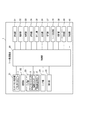
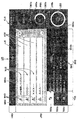
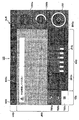
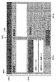
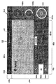
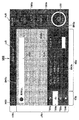
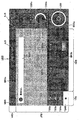
- FIG. 1 is a front view of a sheet manufacturing apparatus 1 according to the present embodiment.
- the sheet manufacturing apparatus 1 is an apparatus for supplying a raw material containing fibers and processing the supplied raw material to manufacture a sheet of a predetermined color in a predetermined shape.
- the raw material supplied to the sheet manufacturing apparatus 1 is paper-like waste paper.
- the raw material supplied to the sheet manufacturing apparatus 1 is not limited to waste paper.
- the first uncolored color and the second uncolored color mean the color of the resin that is not colored.
- the first uncolored resin and the second uncolored resin are different components. Depending on the specifications of the recycled paper to be produced, only one of the resins is used, or both are mixed in a predetermined distribution. Or Both may be the same component.
- the resin cartridge KT will be described later.
- the open / close door 3 is made of a transparent material, and the user can visually recognize the state of the resin cartridge KT stored in the resin cartridge storage portion without opening the open / close door 3. Further, the user can replace the resin cartridge KT of a predetermined color after opening the open / close door 3 and exposing the resin cartridge housing portion.
- the detection unit 25 may cause the remaining amount of the resin stored in the resin cartridge KT to be less than a predetermined amount for each color of the resin cartridge KT based on the detection value input from the predetermined sensor. Detect that there is a sex. Moreover, the detection unit 25 detects that the waste powder stored in the waste powder bag HH exceeds a predetermined amount and the waste powder bag HH needs to be replaced.
- the sheet manufacturing apparatus 1 manufactures a sheet by sequentially executing a plurality of steps.
- the user performs necessary work (work related to water supply to the in-machine tank, replacement of the waste powder bag HH, error elimination, etc.) in order for the sheet manufacturing apparatus 1 to normally execute each process.
- the control unit 20 of the sheet manufacturing apparatus 1 according to the present embodiment appropriately displays a user interface based on the characteristics of the sheet manufacturing apparatus 1 on the touch panel 5 to improve user convenience.
- the user interface displayed on the touch panel 5 of the sheet manufacturing apparatus 1 and the processing executed by the control unit 20 when displaying the user interface will be described together with the work to be performed by the user.
- the touch operation button refers to an operation button that is displayed on the user interface and can be touched.
- the time is expressed as “00:00” or “13:05” in a 24-hour system.
- a period from when the breaker switch 8 and the power switch 7 of the sheet manufacturing apparatus 1 are turned on to when the sheet manufacturing apparatus 1 is shut down is referred to as a “power-on period”.
- the user interface is displayed, images, information, and other objects are displayed on the user interface, and one user interface is transitioned to another user interface.
- the main body is the control unit 20.
- the progress bar PB1 represents the progress of starting the program by extending the bar from left to right in accordance with the progress within a rectangular frame extending in the left-right direction.
- a wording MS1a indicating that the program is being started (“starting processing”) and not turning off the power.
- a word of caution MS1b ("Please do not turn off the power") is displayed.
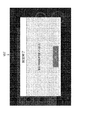
- FIG. 6 is a diagram illustrating the third user interface UI3.
- the initialization process is a process for setting software and hardware to an initial state so that the sheet manufacturing apparatus 1 can start operation.
- the third user interface UI3 is a user interface indicating that the initialization process is being executed.
- the third user interface UI3 includes a progress bar PB3 that represents the progress of the initialization process.
- the wording MS3 indicating that the initialization process is being executed (“The device is being initialized / please wait”). ("/" Represents a line feed. The same applies hereinafter).
- the user can refer to the status display area in a unified manner without changing the place visually recognized by the user interface, so that the current sheet is displayed.
- the state of the manufacturing apparatus 1 can be recognized.
- the A shutdown button SB4 is displayed below the wording MS4b.
- the user can easily recognize that the water supply should be performed by referring to the wording MS4a. Further, the user can easily recognize the water supply procedure by referring to the wording MS4b.
- the water supply procedure includes an operation of opening the front cover 9 and an operation of closing the front cover 9, and the position of the front cover 9 in the sheet manufacturing apparatus 1 is clearly shown by the images IM4a and IM4b. Therefore, the user can accurately recognize the work necessary for water supply by referring to the image IM4a and the image IM4b together with the wording MS4b.
- the unlocking and locking of the front cover 9 are appropriately executed by the control unit 20 at appropriate timing.
- the control unit 20 controls the touch panel control unit 21 to display the fifth user interface UI5 on the touch panel 5 instead of the fourth user interface UI4.
- the control unit 20 controls each unit, executes processing necessary for shutdown, and shuts down the sheet manufacturing apparatus 1.
- the operating time information may be information indicating the length of time that has elapsed since the breaker switch 8 and the power switch 7 were turned on most recently.
- the operation time information is a process in which the sheet manufacturing apparatus 1 manufactures a sheet between a specific time (for example, the latest “00:00”) and the current time regardless of whether the power switch 7 is on or off. It may be information indicating the accumulated time of executing.
- the operation time information may be information indicating a cumulative time during which the sheet manufacturing apparatus 1 executes the process of manufacturing the sheet in the power-on period immediately before the power-on period to which the present time belongs.
- the operation time information may be information indicating the length of the power-on period immediately before the power-on period to which the present time belongs.
- the operation time information is information indicating the state of the sheet manufacturing apparatus 1 and corresponds to the state information.
- the user recognizes the cumulative number of sheets manufactured by the sheet manufacturing apparatus 1 up to the current time on the “day” to which the current time point belongs. Can do.
- the user can switch the information displayed on the manufacturing information image OB5a between the first manufacturing information and the second manufacturing information by a simple operation of touching the manufacturing information image OB5a. .
- the manufacturing information may include other information.
- the manufacturing information may include information indicating the ratio of the number of sheets manufactured at the present time with respect to the number of automatically stopped sheets (described later).
- a raw material information image OB5b that is a circular image is displayed below the manufacturing information image OB5a.
- the raw material information image OB5b also functions as a touch operation button, and information displayed on the image can be switched between first raw material information (described later) and second raw material information (described later) by a touch operation. It is.
- the first raw material information and the second raw material information correspond to “raw material information”.
- information JH5b indicating that the raw material information is displayed in the raw material information image OB5b is displayed below the raw material information image OB5b in association with the raw material information image OB5b.
- FIG. 31 shows the twentieth user interface UI20.
- the twentieth user interface UI20 includes a state display area HR20 and an information display area JR20.
- status information JJ20 (“standby”)
- a menu button MB20 are displayed.
- the operation performed on the sheet manufacturing apparatus 1 is “exchange of the waste powder bag HH”.
- the operation performed on the sheet manufacturing apparatus 1 is not limited to “replacement of the waste powder bag HH”.
- the color is displayed on the right side of the information JH5h indicating the selected recipe in the correspondence information display area RR5 related to the tab TB5a.
- a change instruction button RB5a is displayed.
- the color change instruction button RB5a is a touch operation button operated when changing the color of the manufactured sheet.
- the control unit 20 pops up the 27th user interface UI27.
- FIG. 47 is a diagram showing the 33rd user interface UI33.
- the thirty-third user interface UI33 is a user interface for confirming with the user about stopping the process of manufacturing a sheet.
- the thirty-third user interface UI33 includes a status display area HR33 and an information display area JR33.
- status information JJ33 (“confirmation”) indicating that the process for manufacturing the sheet is confirmed to be stopped is displayed.
- the wording MS33 (“" Stop "button has been pressed" that inquires the user about the pros and cons of stopping the sheet manufacturing process. / Are you sure you want to stop driving? ”) Is displayed.
- the process related to sheet manufacture is not immediately stopped, but the process related to sheet manufacture is stopped by the 33rd user interface UI33. Since the configuration is such that the process is stopped only when the user confirms that the process is performed and the user instructs again, it is possible to prevent a situation where the process is unnecessarily stopped.
- the control unit 20 When the control unit 20 detects that the negative button NB33 of the 33rd user interface UI33 has been touched, the control unit 20 stops the processing relating to the manufacture of the sheet. That is, the control unit 20 continuously executes processing related to sheet manufacturing. When the control unit 20 detects that the affirmative button YB33 of the 33rd user interface UI33 has been touched, the control unit 20 executes a stop preparation process required to stop the process related to sheet manufacture and the 34th user interface.
- the UI 34 is displayed on the touch panel 5.
- the stop preparation process is a process performed in order to normally stop the process related to sheet manufacturing.
- FIG. 48 is a diagram showing the 34th user interface UI34.
- the thirty-fourth user interface UI is a user interface indicating that the stop preparation process described above is being executed and the progress of the stop preparation process.
- the thirty-fourth user interface UI 34 has a progress bar PB 34 that indicates the progress of the stop preparation process.
- the wording MS34 indicating that the stop preparation process is being executed and should be waited ("Operation is stopped / waiting for a while"). Please “.) Is displayed.
- the control unit 20 stops the display of the 34th user interface UI34 and displays the 5th user interface UI5.
- the displayed fifth user interface UI5 is the fifth user interface UI5 displayed when the process is not executed, like the fifth user interface UI5 shown in FIG. 8, and is displayed in the first block BK5a.
- the operation start button UB5 is displayed. The user can start processing related to sheet manufacture by the sheet manufacturing apparatus 1 again by touching the operation start button UB5.
- the control unit 20 displays the 35th user interface UI35.
- a negative button NB35 that is touch-operated when canceling the stop of the process and an affirmative button YB35 that is touch-operated when instructing to stop the process are displayed.
- the When canceling the shutdown the user touches the negative button NB35, and when shutting down, the user touches the positive button YB35. In this way, by confirming with the user about the shutdown by the 35th user interface UI35, it is possible to prevent the shutdown from being performed unnecessarily, as in the 25th user interface UI25 and the 33rd user interface UI33.
- the control unit 20 When detecting that the negative button NB35 of the 35th user interface UI35 is touched, the control unit 20 stops the shutdown. When the control unit 20 detects that the affirmative button YB35 of the 35th user interface UI35 has been touched, the control unit 20 performs a process necessary for shutdown (hereinafter referred to as “end process”) and the 36th user.
- the interface UI 36 is displayed on the touch panel 5.
- the termination process includes waste water treatment.
- the drainage process is a process of draining the water stored in the humidifier to the in-machine tank QT provided inside the apparatus body of the sheet manufacturing apparatus 1 and temporarily storing it in the in-machine tank QT.
- the control part 20 performs a waste_water
- the process which can be performed in parallel with the waste water treatment may be performed in parallel with the waste water treatment.
- FIG. 50 is a diagram showing the 36th user interface UI36.
- the thirty-sixth user interface UI36 is a user interface representing that the wastewater treatment is being executed and the progress of the wastewater treatment.
- the thirty-sixth user interface UI36 has a progress bar PB36 indicating the progress status of the wastewater treatment.
- the wording MS36a (“During processing (drainage process)”) indicating that the drainage process is being executed, and the sheet.
- the wording MS36b (“Do not operate”) is displayed to call attention to the manufacturing apparatus 1 so as not to perform the operation.
- the 37th user interface UI 37 displays an image IM 37b in which the front cover 9 is enlarged in association with the position of the front cover 9 in the image IM 37a.
- a wording MS37a drains water from the onboard tank QT
- a wording MS37b Open the front cover, take out the drainage hose and press the drainage button ... / When drainage is complete "
- the user can easily recognize that the drainage should be performed by referring to the wording MS37a.
- FIG. 52 is a diagram showing the 38th user interface UI38.
- the thirty-eighth user interface UI38 is a user interface that indicates that the end process is being executed and the progress status of the end process.
- the thirty-eighth user interface UI38 has a progress bar PB38 indicating the progress status of the wastewater treatment.
- the wording MS38a (“ending process”) indicating that the end process is being executed, and the sheet manufacturing apparatus 1
- a message MS38b (“Please do not turn off the power”) is displayed to call attention not to turn off the power.
- the control unit 20 When the control unit 20 detects that the end process is completed, the control unit 20 displays a 39th user interface UI39 on the touch panel 5 instead of the 38th user interface UI38.
- FIG. 54 is a diagram showing the 40th user interface.
- the 40th user interface UI40 has a progress bar PB40 indicating the progress of the emergency stop process.
- a wording MS40 (indicating that the emergency stop button 6 has been turned on and that it should wait until the emergency stop process is completed). "Emergency stop button was pressed / please wait") is displayed.
- the control unit 20 detects that the emergency stop process is completed, the control unit 20 stops the display of the 40th user interface UI40 and displays the 41st user interface UI41 on the touch panel 5.
- FIG. 55 is a diagram showing the forty-first user interface UI41.
- the forty-first user interface UI41 includes a state display area HR41 and an information display area JR41.
- status information JJ41 ("Emergency stop") indicating that an emergency stop has occurred is displayed.
- the wording MS41 indicating that the emergency stop process has been completed and stopped, and that the emergency stop button 6 should be turned off after the user turns off the breaker switch 8 is displayed.
- Stop error an error that needs to be stopped in the sheet manufacturing apparatus 1 is generated in the sheet manufacturing apparatus 1 during the processing related to sheet manufacturing
- Stop errors include, for example, a shortage of resin, a shortage of water, a shortage of raw materials, a shortage of consumables used for manufacturing sheets, an error in the transport path (paper jam, etc.), a temperature error of a predetermined mechanism, etc. It is.
- the control unit 20 starts executing the emergency stop process described above, and pops up the forty-second user interface UI42 on the touch panel 5. To do.
- FIG. 56 is a diagram showing the forty-second user interface UI42.
- the forty-second user interface UI42 is a user interface indicating that an emergency stop process is being executed in response to the occurrence of a stop error, and the progress of the emergency stop process.
- the forty-second user interface UI42 has a progress bar PB42 that represents the progress of the emergency stop process.
- the emergency stop process is being executed and the wording MS42 indicating that it should wait (“Operation stopped due to an abnormality in the device). "Please wait ") is displayed.
- the control unit 20 stops the display of the forty-second user interface UI42 and displays the forty-third user interface UI43.
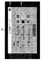
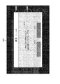
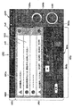
- FIG. 57 shows the 43rd user interface UI43.
- the forty-third user interface UI43 includes a state display area HR43 and an information display area JR43.
- status information JJ43 indicating that an error has occurred is displayed.
- the information display area JR43 of the 43rd user interface UI43 has an area AR43a formed in the upper part and an area AR43b formed in the lower part.
- an item image KG43 on which information indicating the content of the error is displayed is displayed for each error that has occurred.
- the item image KG43 is a touch operation button, and the user touches the corresponding item image KG43 for an error for which detailed information is to be referred to.
- Detailed information regarding the error selected by the user in the area AR43a is displayed in the area AR43b.
- an image IM43 representing a front view of the sheet manufacturing apparatus 1 is displayed on the left side of the area AR43b.
- information about the error, an image, and other objects are appropriately displayed according to the content of the error. For example, when an error has occurred at a predetermined position of the sheet manufacturing apparatus 1, information that clearly indicates the predetermined position is displayed in association with the image IM43.
- information specifying the predetermined position is displayed in association with the image IM43.
- a wording MS43 indicating the detailed content of the error is displayed on the right side of the image IM43. The user can easily and accurately recognize the detailed content of the error by referring to the image IM43 and the wording MS43.
- a shutdown button SB43 for instructing shutdown is displayed below the image IM43.
- the screen displayed when the shutdown button SB43 is touched and the processing of the control unit 20 are as described above.
- an error release button EK43 is displayed on the right side of the shutdown button SB43.
- the error release button EK43 is a touch operation button that is operated when an error is eliminated by performing an operation for eliminating the error for the selected error.
- the control unit 20 determines whether or not the error has been resolved. If the error has been resolved, the control unit 20 displays the item image KG43 related to the corresponding error. Delete from the area AR43a.
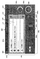
- an unlock button RB43 (FIG. 58) for instructing unlocking is displayed in the area AR43b.
- the FIG. 57 shows the 43rd user interface UI43 in a state where the lock release button RB43 is not displayed
- FIG. 58 shows the 43rd user interface UI43 in a state where the lock release button RB43 is displayed.
- the lock release button RB43 is displayed at a position sandwiched between the shutdown button SB43 and the error release button EK43.
- the control unit 20 controls the lock unit 24 to unlock the predetermined cover. The user can release the lock by performing a simple operation of touching the lock release button RB43 when it is necessary to unlock the predetermined cover in order to eliminate the error.
- a service call error is an error that requires restart of the device, and when it cannot be resolved even after restarting the device, it is necessary to contact a service center in charge of maintenance.
- the control unit 20 detects that a service call error has occurred, the control unit 20 displays the 44th user interface UI 44 on the touch panel 5.
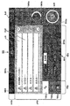
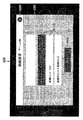
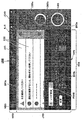
- FIG. 59 is a diagram showing the 44th user interface UI44.
- the forty-fourth user interface UI44 has a status display area HR44 and an information display area JR44.
- status information JJ44 indicating that a service call error has occurred is displayed.
- a message MS44 indicating that a service call error has occurred and how to deal with the service call error ("Service call error has occurred / reinstall the device Even if it is started ... / Contact the service center ... "is displayed.
- error list information EJ44 in which error codes (identification information for uniquely identifying errors) are listed for each error that has occurred is displayed.
- the user can easily and accurately recognize the response to the service call error by referring to the wording MS44.
- the user can accurately report the error that has occurred using the error code displayed in the error list information EJ44.
- device list information SJ44 in which device information related to the sheet manufacturing apparatus 1 is displayed as a list is displayed.
- the apparatus list information SJ44 includes the product name, serial number, firmware version of the sheet manufacturing apparatus 1, and the version of the application that controls the display on the touch panel 5.
- a shutdown button SB44 is displayed below the information display area JR44 of the 44th user interface UI44.
- the sheet manufacturing apparatus 1 is supplied with a raw material including fibers, and processes the supplied raw material to manufacture a sheet.
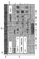
- the sheet manufacturing apparatus 1 includes a control unit 20 that displays a fifth user interface UI5 (user interface) on which raw material information about a raw material to be supplied, manufacturing information about a sheet to be manufactured, and processing information about sheet processing is displayed.
- UI5 user interface
- the user can refer to the raw material information, the manufacturing information, and the processing information at the same time through the same user interface without changing the user interface, and the convenience of the user is improved.
- the raw material information, the manufacturing information, and the processing information are related information, and are assumed to be information that the user desires to refer to and compare at the same time. The user convenience can be improved.
- the manufacturing information includes any one of information on the number of sheets manufactured in a predetermined period and information on the number of sheets manufactured after starting manufacturing of a sheet based on the supplied raw material.
- the raw material is paper-like waste paper. According to this configuration, the convenience of the user can be improved for the sheet manufacturing apparatus 1 that supplies paper waste paper and manufactures the sheet.
- the processing information includes information regarding the blending of each color as information regarding the color of the resin supplied to the predetermined material. According to this configuration, the user can easily and accurately recognize the color composition of the supplied resin by referring to the processing information of the fifth user interface UI5.
- the state information includes information related to an operation time after starting production of a sheet based on the supplied raw material. According to this configuration, the user can easily and accurately recognize the operation time after starting the manufacture of the sheet based on the supplied raw material by referring to the fifth user interface UI5.
- the right transition button RX46 When the right transition button RX46 is touched from this state, the information displayed in the correspondence information display area RR5 is switched from the recipe related information RP5 to the paper feed / discharge information KH5. In this state, the right transition is further performed.
- the button RX46 When the button RX46 is operated, the information displayed in the correspondence information display area RR5 is switched from the paper feed / discharge information KH5 to the consumable information SJ5.
- the information displayed in the correspondence information display area RR5 is selected by touching one of the left transition button LX46 and the right transition button RX46. Even with the configuration, the user can easily make a selection, which is highly convenient for the user.
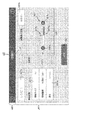
- FIG. 62 is a diagram illustrating a 47th user interface UI47 which is a third modification example of the fifth user interface UI5.
- FIG. 62 components similar to those of the 5th user interface UI5 of FIG. 8 and components similar to the 45th user interface UI45 of FIG. Description is omitted.
- tabs TB5a to TB5c are displayed in the second block BK5b of the fifth user interface UI5.
- the fifth user interface UI5 has a configuration in which information displayed in the corresponding information display area RR5 is changed using the tabs TB5a to TB5c.
- a pull-down menu PM48 is displayed instead of the tabs TB5a to TB5c.
- the pull-down menu PM48 is a pull-down menu in which information (recipe related information RP5, paper feed / discharge information KH5, and consumable information SJ5) displayed in the correspondence information display area RR5 is displayed as an item. In FIG. 63, the pull-down menu PM48 is closed.
- FIG. 64 is a diagram illustrating a 49th user interface UI49 which is a fifth modification example of the fifth user interface UI5.
- the same components as those of the 5th user interface UI5 of FIG. 11 are denoted by the same reference numerals, and the description thereof is omitted.
- FIG. 64 shows the 49th user interface UI49 in a state where the tab TB5b is selected.
- an image IM49a representing the remaining amount of discharged paper is displayed in the correspondence information display area RR5 of the 49th user interface UI49.
- the image IM49c is an image representing the amount of waste powder by a bar whose length varies according to the size of the amount of waste powder. The user can easily and accurately recognize the remaining amount of the water tank by referring to the image IM49b. Further, the user can easily and accurately recognize the amount of waste powder by referring to the image IM49c.
- FIG. 67 is a diagram illustrating a 51st user interface UI51 which is a second modification of the 12th user interface UI12.
- the information display area JR12 of the 51st user interface UI51 displays a bar BR51 whose length in the frame varies depending on the level of the sheet thickness.
- the bar BR51 information indicating the sheet thickness level by characters is displayed. The user can recognize the level of the sheet thickness simply and accurately by referring to the bar BR51.
- a decrement button DB51 for decrementing the value of the sheet thickness level is displayed as a touch operation button.
- an increment button IB51 for incrementing the value of the sheet thickness level is displayed to the right of the right end of the bar BR51.
- an image IM52 is displayed in the information display area JR12 of the 52nd user interface UI52.
- the image IM52 includes an image showing a perspective view of the sheet with an exaggerated thickness and an image of a loupe arranged so that the corner portion of the sheet is positioned within the lens.
- 10 layers are formed in the vertical direction at the corner of the sheet, and the layers correspond to each other by a predetermined color from the bottom to the top according to the level of the sheet thickness.
- the thickness of the paper is expressed by filling in stepwise. When the sheet thickness level is level 1, the lowest layer is filled with a predetermined color inside the loupe lens of the image IM52.
- FIG. 69 is a diagram illustrating a 53rd user interface UI53 which is a fourth modification example of the 12th user interface UI12.
- the same components as those of the 12th user interface UI12 of FIG. 20 and the same components as the 52nd user interface UI52 of FIG. Description is omitted.
- an image IM53 is displayed in the information display area JR12 of the 54th user interface UI54.
- the image IM53 is a diagram in which the image of the loupe is removed from the image IM52 described with reference to FIG. 68 and the separation of each layer of the sheet is represented by dotted lines. According to the 53rd user interface UI53, the same effect as that of the 52nd user interface UI52 can be obtained.
Landscapes
- Engineering & Computer Science (AREA)
- Business, Economics & Management (AREA)
- Human Resources & Organizations (AREA)
- Theoretical Computer Science (AREA)
- Manufacturing & Machinery (AREA)
- Physics & Mathematics (AREA)
- Economics (AREA)
- General Physics & Mathematics (AREA)
- Strategic Management (AREA)
- General Business, Economics & Management (AREA)
- General Engineering & Computer Science (AREA)
- Entrepreneurship & Innovation (AREA)
- Marketing (AREA)
- Tourism & Hospitality (AREA)
- Life Sciences & Earth Sciences (AREA)
- Development Economics (AREA)
- Operations Research (AREA)
- Wood Science & Technology (AREA)
- Health & Medical Sciences (AREA)
- Educational Administration (AREA)
- Forests & Forestry (AREA)
- Game Theory and Decision Science (AREA)
- Primary Health Care (AREA)
- Quality & Reliability (AREA)
- Textile Engineering (AREA)
- General Health & Medical Sciences (AREA)
- Human Computer Interaction (AREA)
- User Interface Of Digital Computer (AREA)
- Nonwoven Fabrics (AREA)
- Control Or Security For Electrophotography (AREA)
Abstract
The purpose of the invention is to enhance usability for users in relation to the displaying of a user interface in a sheet manufacturing device for manufacturing sheets. Disclosed is a sheet manufacturing device 1 that manufactures a sheet by being supplied with a material including a fiber and processing the supplied material, the sheet manufacturing device 1 comprising a control unit 20 that displays a user interface displaying material information related to the supplied material, manufacturing information related to the sheet to be manufactured, and processing information related to the processing of the sheet.
Description
本発明は、シート製造装置、及び、シート製造装置の制御方法に関する。
The present invention relates to a sheet manufacturing apparatus and a control method for the sheet manufacturing apparatus.
従来、シート製造装置(古紙再生処理装置)について、装置の運転状態を容易に管理するための情報が表示されたユーザーインターフェース(画面)を表示する技術が知られている(例えば、特許文献1参照)。
2. Description of the Related Art Conventionally, a technique for displaying a user interface (screen) on which information for easily managing the operation state of a sheet manufacturing apparatus (used paper recycling processing apparatus) is displayed (see, for example, Patent Document 1). ).
しかしながら、上述した特許文献1では、1つのユーザーインターフェースに、同一又は近似する内容の情報が表示される構成のため、ユーザーが同時に参照することを望むと想定される情報がそれぞれ異なるユーザーインターフェースに表示される場合がある。この場合、ユーザーは、ユーザーインターフェースを遷移させてそれぞれの情報を参照する必要があり、ユーザーの利便性の向上に改善の余地がある。
本発明は、上述した事情に鑑みてなされたものであり、シートを製造するシート製造装置について、ユーザーインターフェースの表示に関し、ユーザーの利便性を向上することを目的とする。 However, in the above-describedPatent Document 1, since information having the same or similar contents is displayed on one user interface, information assumed to be referred to by the user at the same time is displayed on different user interfaces. May be. In this case, the user needs to refer to each information by changing the user interface, and there is room for improvement in improving the convenience of the user.
The present invention has been made in view of the above-described circumstances, and an object of the sheet manufacturing apparatus for manufacturing a sheet is to improve user convenience regarding display of a user interface.
本発明は、上述した事情に鑑みてなされたものであり、シートを製造するシート製造装置について、ユーザーインターフェースの表示に関し、ユーザーの利便性を向上することを目的とする。 However, in the above-described
The present invention has been made in view of the above-described circumstances, and an object of the sheet manufacturing apparatus for manufacturing a sheet is to improve user convenience regarding display of a user interface.
上記課題を解決するために、本発明のシート製造装置は、繊維を含む原料が供給され、供給された前記原料を加工してシートを製造するシート製造装置であって、供給される前記原料に関する原料情報と、製造する前記シートに関する製造情報と、前記シートの加工に関する加工情報とが表示されたユーザーインターフェースを表示させる制御部を備える。
本発明の構成によれば、ユーザーは、原料情報と、製造情報と、加工情報について、ユーザーインターフェースを遷移させることなく、同一のユーザーインターフェースを介して同時に参照でき、ユーザーの利便性が向上する。特に、原料情報と、製造情報と、加工情報とは、内容が関連した情報であり、ユーザーが同時に参照し、比較することを望む情報と想定されるため、本発明によれば、より的確にユーザーの利便性を向上できる。 In order to solve the above problems, a sheet manufacturing apparatus according to the present invention is a sheet manufacturing apparatus for manufacturing a sheet by supplying a raw material containing fibers and processing the supplied raw material, and relates to the supplied raw material. A control unit is provided that displays a user interface on which raw material information, manufacturing information regarding the sheet to be manufactured, and processing information regarding processing of the sheet are displayed.
According to the configuration of the present invention, the user can refer to the raw material information, the manufacturing information, and the processing information at the same time through the same user interface without changing the user interface, and the convenience for the user is improved. In particular, the raw material information, the manufacturing information, and the processing information are information related to the contents, and are assumed to be information that the user desires to refer to and compare at the same time. User convenience can be improved.
また、本発明は、前記原料情報は、所定の期間で供給され消費された前記原料の量に関する情報と、前記原料の残量に関する情報と、供給された前記原料に基づく前記シートの製造を開始した後に消費した前記原料の量に関する情報とのいずれか1つの情報を少なくとも含む。
本発明の構成によれば、ユーザーは、ユーザーインターフェースを参照することにより、簡易に的確に、所定の期間で供給され消費された原料の量に関する情報と、原料の残量に関する情報と、供給された原料に基づくシートの製造を開始した後に消費した原料の量に関する情報とのいずれかについて、認識できる。 In the present invention, the raw material information starts information on the amount of the raw material supplied and consumed in a predetermined period, information on the remaining amount of the raw material, and production of the sheet based on the supplied raw material. And at least one piece of information related to the amount of the raw material consumed after.
According to the configuration of the present invention, the user can easily and accurately refer to the user interface to supply information on the amount of raw material supplied and consumed in a predetermined period, information on the remaining amount of raw material, and It is possible to recognize any of the information regarding the amount of the raw material consumed after starting the production of the sheet based on the raw material.
また、本発明は、前記製造情報は、所定の期間で製造された前記シートの枚数に関する情報と、供給された前記原料に基づく前記シートの製造を開始した後に製造された前記シートの枚数に関する情報とのいずれか1つの情報を少なくとも含む。
本発明の構成によれば、ユーザーは、ユーザーインターフェースを参照することにより、簡易に的確に、所定の期間で製造されたシートの枚数に関する情報と、供給された原料に基づくシートの製造を開始した後に製造されたシートの枚数に関する情報とのいずれかについて、認識できる。 In the present invention, the manufacturing information includes information on the number of sheets manufactured in a predetermined period, and information on the number of sheets manufactured after starting manufacturing of the sheet based on the supplied raw material. And at least one piece of information.
According to the configuration of the present invention, the user starts manufacturing the sheet based on the information on the number of sheets manufactured in a predetermined period and the supplied raw material easily and accurately by referring to the user interface. Any of the information regarding the number of sheets manufactured later can be recognized.
また、本発明は、前記原料は紙状である。
本発明の構成によれば、紙状の原料が供給され、シートを製造するシート製造装置について、ユーザーの利便性を向上できる。 In the present invention, the raw material is paper.
According to the configuration of the present invention, the convenience of the user can be improved for a sheet manufacturing apparatus that supplies a sheet-like raw material and manufactures a sheet.
また、本発明は、前記ユーザーインターフェースは、表示される情報の内容に応じた複数のブロックから構成されており、前記原料情報と前記製造情報とは、同一の前記ブロックに表示される。
ここで、原料情報の内容と製造情報の内容とは関連しており、ユーザーは、原料情報と、製造情報とを同時に参照し、これら情報の内容を比較することを望むものと想定される。以上を踏まえ、製造情報と、原料情報とが、同一のブロックに表示されることにより、ユーザーは、製造情報と原料情報とが関連する情報であることを的確に認識できると共に、これら情報を同時に参照し、これら情報の内容を的確に比較することができる。 According to the present invention, the user interface includes a plurality of blocks corresponding to the contents of information to be displayed, and the raw material information and the manufacturing information are displayed in the same block.
Here, the content of the raw material information and the content of the manufacturing information are related, and it is assumed that the user desires to refer to the raw material information and the manufacturing information at the same time and compare the contents of these information. Based on the above, the manufacturing information and the raw material information are displayed in the same block, so that the user can accurately recognize that the manufacturing information and the raw material information are related, and at the same time, It is possible to refer to and compare the contents of these information accurately.
また、本発明は、所定の色の前記シートを製造可能であり、前記加工情報は、製造する前記シートの色に関する情報を含む。
本発明の構成によれば、ユーザーは、ユーザーインターフェースに表示された加工情報を参照することにより、製造するシートの色について、簡易に的確に認識できる。 In the present invention, the sheet having a predetermined color can be manufactured, and the processing information includes information on the color of the sheet to be manufactured.
According to the configuration of the present invention, the user can easily and accurately recognize the color of the sheet to be manufactured by referring to the processing information displayed on the user interface.
また、本発明は、複数色の樹脂を色ごとに貯留する複数の樹脂カートリッジを備え、シートを製造する所定の工程で、前記原料に基づく所定の材料に対して、1又は複数の前記樹脂カートリッジから樹脂が供給され、前記加工情報は、製造する前記シートの色に関する情報として、前記所定の材料に対して供給される樹脂の色に関する情報を含む。
本発明の構成によれば、ユーザーは、ユーザーインターフェースの加工情報を参照することにより、所定の材料に対して供給される樹脂の色について、簡易に的確に認識できる。 Further, the present invention includes a plurality of resin cartridges that store a plurality of colors of resins for each color, and one or a plurality of the resin cartridges for a predetermined material based on the raw material in a predetermined process of manufacturing a sheet. The processing information includes information on the color of the resin supplied to the predetermined material as information on the color of the sheet to be manufactured.
According to the configuration of the present invention, the user can easily and accurately recognize the color of the resin supplied to a predetermined material by referring to the processing information of the user interface.
また、本発明は、前記加工情報は、前記所定の材料に対して供給される樹脂の色に関する情報として、各色の配合に関する情報を含む。
本発明の構成によれば、ユーザーは、ユーザーインターフェースの加工情報を参照することにより、供給される樹脂の色の配合について、簡易に的確に認識できる。 According to the present invention, the processing information includes information relating to the composition of each color as information relating to the color of the resin supplied to the predetermined material.
According to the configuration of the present invention, the user can easily and accurately recognize the color composition of the supplied resin by referring to the processing information of the user interface.
また、本発明は、所定のサイズの前記シートを製造可能であり、前記加工情報は、製造する前記シートのサイズに関する情報を含む。
本発明の構成によれば、ユーザーは、ユーザーインターフェースの加工情報を参照することにより、製造するシートのサイズについて、簡易に的確に認識できる。 In the present invention, the sheet having a predetermined size can be manufactured, and the processing information includes information on the size of the sheet to be manufactured.
According to the configuration of the present invention, the user can easily and accurately recognize the size of the sheet to be manufactured by referring to the processing information of the user interface.
また、本発明は、所定の厚さの前記シートを製造可能であり、前記加工情報は、製造する前記シートの厚さに関する情報を含む。
本発明の構成によれば、ユーザーは、ユーザーインターフェースの加工情報を参照することにより、製造するシートの厚さについて、簡易に的確に認識できる。 Moreover, this invention can manufacture the said sheet | seat of predetermined | prescribed thickness, and the said process information contains the information regarding the thickness of the said sheet | seat to manufacture.
According to the configuration of the present invention, the user can easily and accurately recognize the thickness of the sheet to be manufactured by referring to the processing information of the user interface.
また、本発明は、前記制御部は、前記ユーザーインターフェースに、警告に関する警告情報を一覧表示する。
本発明の構成によれば、ユーザーは、ユーザーインターフェースを参照することにより、警告に関し簡易に的確に認識できる。 In the present invention, the control unit displays a list of warning information regarding warnings on the user interface.
According to the configuration of the present invention, the user can easily and accurately recognize the warning by referring to the user interface.
また、本発明は、前記制御部は、前記ユーザーインターフェースに、装置本体の状態に関する状態情報を表示する。
本発明の構成によれば、ユーザーは、ユーザーインターフェースを参照することにより、装置本体の状態について、簡易に的確に認識できる。 According to the present invention, the control unit displays status information related to the status of the apparatus main body on the user interface.
According to the configuration of the present invention, the user can easily and accurately recognize the state of the apparatus main body by referring to the user interface.
また、本発明は、前記状態情報は、前記シートを製造する処理を実行中か否かを示す情報を含む。
本発明の構成によれば、ユーザーは、ユーザーインターフェースを参照することにより、シート製造装置1がシートを製造する処理を実行中か否かについて、簡易に的確に認識することができる。 In the present invention, the state information includes information indicating whether or not a process for manufacturing the sheet is being executed.
According to the configuration of the present invention, the user can easily and accurately recognize whether or not thesheet manufacturing apparatus 1 is executing a process of manufacturing a sheet by referring to the user interface.
本発明の構成によれば、ユーザーは、ユーザーインターフェースを参照することにより、シート製造装置1がシートを製造する処理を実行中か否かについて、簡易に的確に認識することができる。 In the present invention, the state information includes information indicating whether or not a process for manufacturing the sheet is being executed.
According to the configuration of the present invention, the user can easily and accurately recognize whether or not the
また、本発明は、前記状態情報は、供給された前記原料に基づく前記シートの製造を開始してからの運転時間に関する情報を含む。
本発明の構成によれば、ユーザーは、ユーザーインターフェースを参照することにより、供給された原料に基づくシートの製造を開始してからの運転時間について、簡易に的確に認識できる。 Further, according to the present invention, the state information includes information on an operation time after starting production of the sheet based on the supplied raw material.
According to the configuration of the present invention, the user can easily and accurately recognize the operation time after starting production of the sheet based on the supplied raw material by referring to the user interface.
また、本発明は、前記ユーザーインターフェースは、前記シートを製造する処理の開始を指示する操作ボタンを有し、前記制御部は、前記操作ボタンが操作されたことを検出した場合、前記シートを製造する処理を開始する。
本発明の構成によれば、ユーザーは、ユーザーインターフェースから他のユーザーインターフェースに遷移させることなく、操作ボタンを操作するという簡易な作業を行うことによって、シートの製造を開始させることができる。 In the present invention, the user interface includes an operation button for instructing start of a process for manufacturing the sheet, and the control unit manufactures the sheet when detecting that the operation button is operated. To start the process.
According to the configuration of the present invention, the user can start production of a sheet by performing a simple operation of operating the operation button without making a transition from the user interface to another user interface.
また、上記課題を解決するため、本発明は、繊維を含む原料が供給され、供給された前記原料を加工してシートを製造するシート製造装置の制御方法であって、供給される前記原料に関する原料情報と、製造する前記シートに関する製造情報と、前記シートの加工に関する加工情報とが表示されたユーザーインターフェースを表示させる。
本発明の構成によれば、ユーザーは、原料情報と、製造情報と、加工情報について、ユーザーインターフェースを遷移させることなく、同一のユーザーインターフェースを介して同時に参照でき、ユーザーの利便性が向上する。特に、原料情報と、製造情報と、加工情報とは、内容が関連した情報であり、ユーザーが同時に参照し、比較することを望む情報と想定されるため、本発明によれば、より的確にユーザーの利便性を向上できる。 Moreover, in order to solve the said subject, this invention is a control method of the sheet manufacturing apparatus which processes the supplied said raw material and manufactures a sheet | seat by supplying the raw material containing a fiber, Comprising: The said raw material supplied A user interface displaying raw material information, manufacturing information about the sheet to be manufactured, and processing information about processing of the sheet is displayed.
According to the configuration of the present invention, the user can refer to the raw material information, the manufacturing information, and the processing information at the same time through the same user interface without changing the user interface, and the convenience for the user is improved. In particular, the raw material information, the manufacturing information, and the processing information are information related to the contents, and are assumed to be information that the user desires to refer to and compare at the same time. User convenience can be improved.
以下、図面を参照して本発明の実施形態について説明する。
図1は、本実施形態に係るシート製造装置1の正面図である。なお、図1を用いた説明において、上下左右の各方向は、図中で矢印により示す方向に対応する。
シート製造装置1は、繊維を含む原料が供給され、供給された原料を加工して所定の形状で所定の色のシートを製造する装置である。本実施形態では、シート製造装置1に供給される原料は、紙状の古紙である。ただし、シート製造装置1に供給される原料は、古紙に限らない。シート製造装置1に供給される原料は繊維を含むものであればよく、例えば、パルプ、パルプシート、不織布を含む布、或いは織物等が挙げられる。
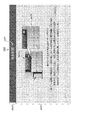
図1に示すように、シート製造装置1は、略直方体の筐体2を備える。筐体2の正面2aの中央上部には、正面2aの上部に設けられた開口を開閉する開閉扉3が設けられる。開閉扉3には取っ手3aが設けられ、ユーザーは、取っ手3aを用いて開閉扉3を開状態又は閉状態とすることができる。開閉扉3が開状態となると、樹脂カートリッジ収納部が露出する。樹脂カートリッジ収納部は、筐体2の内部の開閉扉3に対応する位置に設けられ、第1無着色(P)の樹脂が貯留する樹脂カートリッジKT1と、第2無着色(S)の樹脂が貯留する樹脂カートリッジKT2と、白色(W)の樹脂が貯留する樹脂カートリッジKT3と、イエロー(Y)の樹脂が貯留する樹脂カートリッジKT4と、マゼンタ(M)の樹脂が貯留する樹脂カートリッジKT5と、シアン(C)の樹脂が貯留する樹脂カートリッジKT6とが収納される収納部である。以下、樹脂カートリッジKT1~KT6を区別しない場合、「樹脂カートリッジKT」と表現する。第1無着色、及び、第2無着色は、着色が施されていない樹脂の色を意味する。第1無着色の樹脂と、第2無着色の樹脂とは異なる成分であり、製造する再生紙の仕様に応じて、片方の樹脂のみ使用したり、両者を所定の配分で混合して使用したりする。なお、両者は同じ成分であってもかまわない。樹脂カートリッジKTについては、後述する。開閉扉3は、透明の素材で構成されており、ユーザーは、開閉扉3を開状態とすることなく、樹脂カートリッジ収納部に収納された樹脂カートリッジKTの状態を視認できる。また、ユーザーは、開閉扉3を開状態として樹脂カートリッジ収納部を露出した後、所定の色の樹脂カートリッジKTを交換できる。 Hereinafter, embodiments of the present invention will be described with reference to the drawings.
FIG. 1 is a front view of asheet manufacturing apparatus 1 according to the present embodiment. In the description with reference to FIG. 1, the upper, lower, left, and right directions correspond to directions indicated by arrows in the drawing.
Thesheet manufacturing apparatus 1 is an apparatus for supplying a raw material containing fibers and processing the supplied raw material to manufacture a sheet of a predetermined color in a predetermined shape. In this embodiment, the raw material supplied to the sheet manufacturing apparatus 1 is paper-like waste paper. However, the raw material supplied to the sheet manufacturing apparatus 1 is not limited to waste paper. The raw material supplied to the sheet manufacturing apparatus 1 should just contain a fiber, for example, a pulp, a pulp sheet, the cloth containing a nonwoven fabric, or a textile fabric etc. are mentioned.
As shown in FIG. 1, thesheet manufacturing apparatus 1 includes a substantially rectangular parallelepiped housing 2. An opening / closing door 3 that opens and closes an opening provided in the upper portion of the front surface 2a is provided at the center upper portion of the front surface 2a of the housing 2. The door 3 is provided with a handle 3a, and the user can open or close the door 3 using the handle 3a. When the open / close door 3 is opened, the resin cartridge housing portion is exposed. The resin cartridge storage portion is provided at a position corresponding to the open / close door 3 inside the housing 2, and the resin cartridge KT <b> 1 storing the first uncolored (P) resin and the second uncolored (S) resin A resin cartridge KT2 for storing, a resin cartridge KT3 for storing white (W) resin, a resin cartridge KT4 for storing yellow (Y) resin, a resin cartridge KT5 for storing magenta (M) resin, and cyan (C) is a storage portion in which the resin cartridge KT6 storing the resin is stored. Hereinafter, when the resin cartridges KT1 to KT6 are not distinguished, they are expressed as “resin cartridge KT”. The first uncolored color and the second uncolored color mean the color of the resin that is not colored. The first uncolored resin and the second uncolored resin are different components. Depending on the specifications of the recycled paper to be produced, only one of the resins is used, or both are mixed in a predetermined distribution. Or Both may be the same component. The resin cartridge KT will be described later. The open / close door 3 is made of a transparent material, and the user can visually recognize the state of the resin cartridge KT stored in the resin cartridge storage portion without opening the open / close door 3. Further, the user can replace the resin cartridge KT of a predetermined color after opening the open / close door 3 and exposing the resin cartridge housing portion.
図1は、本実施形態に係るシート製造装置1の正面図である。なお、図1を用いた説明において、上下左右の各方向は、図中で矢印により示す方向に対応する。
シート製造装置1は、繊維を含む原料が供給され、供給された原料を加工して所定の形状で所定の色のシートを製造する装置である。本実施形態では、シート製造装置1に供給される原料は、紙状の古紙である。ただし、シート製造装置1に供給される原料は、古紙に限らない。シート製造装置1に供給される原料は繊維を含むものであればよく、例えば、パルプ、パルプシート、不織布を含む布、或いは織物等が挙げられる。
図1に示すように、シート製造装置1は、略直方体の筐体2を備える。筐体2の正面2aの中央上部には、正面2aの上部に設けられた開口を開閉する開閉扉3が設けられる。開閉扉3には取っ手3aが設けられ、ユーザーは、取っ手3aを用いて開閉扉3を開状態又は閉状態とすることができる。開閉扉3が開状態となると、樹脂カートリッジ収納部が露出する。樹脂カートリッジ収納部は、筐体2の内部の開閉扉3に対応する位置に設けられ、第1無着色(P)の樹脂が貯留する樹脂カートリッジKT1と、第2無着色(S)の樹脂が貯留する樹脂カートリッジKT2と、白色(W)の樹脂が貯留する樹脂カートリッジKT3と、イエロー(Y)の樹脂が貯留する樹脂カートリッジKT4と、マゼンタ(M)の樹脂が貯留する樹脂カートリッジKT5と、シアン(C)の樹脂が貯留する樹脂カートリッジKT6とが収納される収納部である。以下、樹脂カートリッジKT1~KT6を区別しない場合、「樹脂カートリッジKT」と表現する。第1無着色、及び、第2無着色は、着色が施されていない樹脂の色を意味する。第1無着色の樹脂と、第2無着色の樹脂とは異なる成分であり、製造する再生紙の仕様に応じて、片方の樹脂のみ使用したり、両者を所定の配分で混合して使用したりする。なお、両者は同じ成分であってもかまわない。樹脂カートリッジKTについては、後述する。開閉扉3は、透明の素材で構成されており、ユーザーは、開閉扉3を開状態とすることなく、樹脂カートリッジ収納部に収納された樹脂カートリッジKTの状態を視認できる。また、ユーザーは、開閉扉3を開状態として樹脂カートリッジ収納部を露出した後、所定の色の樹脂カートリッジKTを交換できる。 Hereinafter, embodiments of the present invention will be described with reference to the drawings.
FIG. 1 is a front view of a
The
As shown in FIG. 1, the
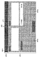
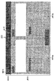
図1に示すように、筐体2の正面2aにおいて、開閉扉3の右方には、タッチパネル5が設けられる。タッチパネル5は、シート製造装置1が、オフィスや、工場、その他の空間に設けられた場合において、当該装置を操作することが想定される成人のユーザーが、姿勢を変えることなく簡易に視認でき、かつ、簡易にタッチ操作ができる高さの位置に設けられる。一例として、タッチパネル5は、タッチパネル5の中央部の高さが略1.4メートルとなる位置に設けられる。後述するように、タッチパネル5には、シート製造装置1に関する各種情報が表示されたユーザーインターフェースが表示される。
As shown in FIG. 1, a touch panel 5 is provided on the right side of the opening / closing door 3 on the front surface 2 a of the housing 2. When the sheet manufacturing apparatus 1 is provided in an office, factory, or other space, the touch panel 5 can be easily viewed by an adult user who is supposed to operate the apparatus without changing the posture. And it is provided in the position of the height which can perform touch operation easily. As an example, the touch panel 5 is provided at a position where the height of the central portion of the touch panel 5 is approximately 1.4 meters. As will be described later, the touch panel 5 displays a user interface on which various information related to the sheet manufacturing apparatus 1 is displayed.
図1に示すように、筐体2の正面2aにおいて、タッチパネル5の上方には、非常停止ボタン6が設けられる。非常停止ボタン6は、シート製造装置1がシートを製造する処理を実行中の場合において、当該処理を緊急で停止することを指示するボタンである。後述するように、ユーザーによって非常停止ボタン6がオンされた場合、対応する情報がユーザーインターフェースに表示された上で、シート製造装置1によるシートの製造に係る処理が停止する。ユーザーは、ユーザーインターフェースを参照することにより、適切な対応をとることができる。なお、非常停止ボタン6は、押下する度にオンとオフを交互に切り替えるタイプのスイッチであるが、所謂シーソー型やレバー型のスイッチであってもよい。
As shown in FIG. 1, an emergency stop button 6 is provided above the touch panel 5 on the front surface 2 a of the housing 2. The emergency stop button 6 is a button for instructing to stop the process urgently when the sheet manufacturing apparatus 1 is executing a process for manufacturing a sheet. As will be described later, when the emergency stop button 6 is turned on by the user, the corresponding information is displayed on the user interface, and the process related to the sheet manufacturing by the sheet manufacturing apparatus 1 is stopped. The user can take an appropriate action by referring to the user interface. The emergency stop button 6 is a type of switch that switches between on and off alternately each time it is pressed, but may be a so-called seesaw type or lever type switch.
図1に示すように、筐体2の正面2aにおいて、タッチパネルの下方には、押下式の電源スイッチ7が設けられる。また、筐体2の左側面2bの上下方向の中央部には、回転式のブレーカースイッチ8が設けられる。ユーザーは、シート製造装置1が起動してない状態において、シート製造装置1を起動させ、シート製造装置1についてシートを製造する処理を開始できる状態とするためには、ブレーカースイッチ8をオンした後、電源スイッチ7をオンする必要がある。後述するように、ブレーカースイッチ8の操作、及び、電源スイッチ7の操作について、タッチパネル5に対応する情報が表示されたユーザーインターフェースが表示される。ユーザーは、ユーザーインターフェースを参照することにより、適切な対応をとることができる。
As shown in FIG. 1, on the front surface 2a of the housing 2, a push-down power switch 7 is provided below the touch panel. In addition, a rotary breaker switch 8 is provided at the center of the left side surface 2b of the housing 2 in the vertical direction. After the breaker switch 8 is turned on, the user activates the sheet manufacturing apparatus 1 in a state in which the sheet manufacturing apparatus 1 is not activated, and allows the sheet manufacturing apparatus 1 to start a process for producing a sheet. The power switch 7 needs to be turned on. As will be described later, a user interface on which information corresponding to the touch panel 5 is displayed for the operation of the breaker switch 8 and the operation of the power switch 7 is displayed. The user can take an appropriate action by referring to the user interface.
図1に示すように、筐体2の正面2aにおいて、開閉扉3の下方には、前カバー9が設けられる。前カバー9には取っ手9aが設けられる。ユーザーは、取っ手9aを用いて前カバー9を開状態又は閉状態とすることができる。前カバー9が開状態となると、筐体2の内部に設けられた機内タンク収納部が露出する。機内タンク収納部は、筐体2の内部の開閉扉3に対応する位置に設けられ、少なくとも機内タンクQT(後述)が収納される収納部である。前カバー9は、図示しないロック機構によるロックが解除された状態の場合にのみ開状態とすることが可能である。
後述するように、機内タンク収納部に収納された機内タンクQTには、所定のタイミングで外部から水を供給し、また、外部に水を排出する必要がある。そして、機内タンクQTへの水の供給、及び、機内タンクQTからの水の排出に際し、タッチパネル5には、対応する情報が表示されたユーザーインターフェースが表示される。ユーザーは、ユーザーインターフェースを参照することにより、適切な対応をとることができる。 As shown in FIG. 1, afront cover 9 is provided below the open / close door 3 on the front surface 2 a of the housing 2. The front cover 9 is provided with a handle 9a. The user can open or close the front cover 9 using the handle 9a. When the front cover 9 is in the open state, the in-machine tank storage provided inside the housing 2 is exposed. The on-board tank storage unit is a storage unit that is provided at a position corresponding to the open / close door 3 inside the housing 2 and stores at least an on-board tank QT (described later). The front cover 9 can be opened only when the lock by a lock mechanism (not shown) is released.
As will be described later, it is necessary to supply water from the outside to the on-board tank QT stored in the on-board tank storage section at a predetermined timing and to discharge the water to the outside. When the water is supplied to the onboard tank QT and discharged from the onboard tank QT, thetouch panel 5 displays a user interface on which corresponding information is displayed. The user can take an appropriate action by referring to the user interface.
後述するように、機内タンク収納部に収納された機内タンクQTには、所定のタイミングで外部から水を供給し、また、外部に水を排出する必要がある。そして、機内タンクQTへの水の供給、及び、機内タンクQTからの水の排出に際し、タッチパネル5には、対応する情報が表示されたユーザーインターフェースが表示される。ユーザーは、ユーザーインターフェースを参照することにより、適切な対応をとることができる。 As shown in FIG. 1, a
As will be described later, it is necessary to supply water from the outside to the on-board tank QT stored in the on-board tank storage section at a predetermined timing and to discharge the water to the outside. When the water is supplied to the onboard tank QT and discharged from the onboard tank QT, the
図1に示すように、筐体2の正面2aの下部には、正面2aから突出した状態で、給紙カセット11が設けられる。給紙カセット11は、原料となる古紙が収容される装置である。古紙に基づくシートの製造に際し、給紙カセット11に収容された古紙が所定の手段により筐体2の内部に供給される。図示は省略するが給紙カセット11には、オプションとして、古紙を収容可能な給紙トレイを装着することができる。
図1に示すように、筐体2の正面2aの左端部には、筐体2が後方に向かって凹むことによって空間が形成されており、当該空間には、排紙トレイ12が設けられる。排紙トレイ12は、シート製造装置1により製造されたシートが、順次、排紙され、貯留される装置である。排紙トレイ12には、オプションとして、排紙スタッカーを装着することができる。 As shown in FIG. 1, apaper feed cassette 11 is provided at a lower portion of the front surface 2 a of the housing 2 in a state of protruding from the front surface 2 a. The paper feed cassette 11 is a device that stores used paper as a raw material. When manufacturing a sheet based on used paper, the used paper stored in the paper feed cassette 11 is supplied into the housing 2 by a predetermined means. Although not shown, the paper feed cassette 11 can be optionally equipped with a paper feed tray that can accommodate used paper.
As shown in FIG. 1, a space is formed in the left end portion of thefront surface 2 a of the housing 2 by the housing 2 being recessed rearward, and a paper discharge tray 12 is provided in the space. The sheet discharge tray 12 is a device that sequentially discharges and stores sheets manufactured by the sheet manufacturing apparatus 1. A paper discharge stacker can be attached to the paper discharge tray 12 as an option.
図1に示すように、筐体2の正面2aの左端部には、筐体2が後方に向かって凹むことによって空間が形成されており、当該空間には、排紙トレイ12が設けられる。排紙トレイ12は、シート製造装置1により製造されたシートが、順次、排紙され、貯留される装置である。排紙トレイ12には、オプションとして、排紙スタッカーを装着することができる。 As shown in FIG. 1, a
As shown in FIG. 1, a space is formed in the left end portion of the
図1に示すように、筐体2の右側面2cの所定の位置には、廃粉ボックスカバー13が設けられる。廃粉ボックスカバー13が開状態となると、筐体2の内部に設けられた廃粉袋収納部が露出する。廃粉袋収納部は、筐体2の廃粉ボックスカバー13に対応する位置に設けられ、少なくとも廃粉袋HH(後述)が収納される収納部である。廃粉ボックスカバー13は、図示しないロック機構によるロックが解除された状態の場合にのみ開状態とすることが可能である。
後述するように、廃粉袋HHには、シートを製造する所定の工程で生じる廃粉が貯留される。ユーザーは、廃粉袋HHに貯留された廃粉の量が所定量を上回った場合、古い廃粉袋HHを新しい廃粉袋HHに交換する必要がある。そして、廃粉袋HHの交換に際し、タッチパネル5には、対応する情報が表示されたユーザーインターフェースが表示される。ユーザーは、ユーザーインターフェースを参照することにより、適切な対応をとることができる。 As shown in FIG. 1, a wastepowder box cover 13 is provided at a predetermined position on the right side surface 2 c of the housing 2. When the waste powder box cover 13 is in the open state, the waste powder bag storage portion provided inside the housing 2 is exposed. The waste powder bag storage unit is a storage unit that is provided at a position corresponding to the waste powder box cover 13 of the housing 2 and stores at least a waste powder bag HH (described later). The waste powder box cover 13 can be opened only when it is unlocked by a lock mechanism (not shown).
As will be described later, waste powder generated in a predetermined process for manufacturing a sheet is stored in the waste powder bag HH. When the amount of waste powder stored in the waste powder bag HH exceeds a predetermined amount, the user needs to replace the old waste powder bag HH with a new waste powder bag HH. When the waste bag HH is replaced, a user interface on which corresponding information is displayed is displayed on thetouch panel 5. The user can take an appropriate action by referring to the user interface.
後述するように、廃粉袋HHには、シートを製造する所定の工程で生じる廃粉が貯留される。ユーザーは、廃粉袋HHに貯留された廃粉の量が所定量を上回った場合、古い廃粉袋HHを新しい廃粉袋HHに交換する必要がある。そして、廃粉袋HHの交換に際し、タッチパネル5には、対応する情報が表示されたユーザーインターフェースが表示される。ユーザーは、ユーザーインターフェースを参照することにより、適切な対応をとることができる。 As shown in FIG. 1, a waste
As will be described later, waste powder generated in a predetermined process for manufacturing a sheet is stored in the waste powder bag HH. When the amount of waste powder stored in the waste powder bag HH exceeds a predetermined amount, the user needs to replace the old waste powder bag HH with a new waste powder bag HH. When the waste bag HH is replaced, a user interface on which corresponding information is displayed is displayed on the
次に、シート製造装置1がシートを製造するときの基本的な工程について説明する。
図2は、シートを製造する際に実行される工程のフローを示す図である。
図2に示すように、まず、供給工程K1が実行される。供給工程K1では、給紙カセット11等から筐体2に古紙が供給される。
供給工程K1の次に、粗砕工程K2が実行される。粗砕工程K2では、原料として古紙が、空気中で切断され、1~数センチ四方またはそれ以下のサイズの紙片に裁断される。
粗砕工程K2の次に、解繊工程K3が実行される。解繊工程K3では、粗砕工程K2で裁断された原料が、繊維状に解きほぐされて解繊されることによって、解繊物が生成される。
解繊工程K3の次に、選別工程K4が実行される。選別工程K4では、解繊物から長い繊維(長繊維。)や、十分に解繊されなかった未解繊片が空気中で選別されて取り除かれる。取り除かれた繊維や、未解繊片は、廃粉として、廃粉袋HHに排出され、貯留される。
選別工程K4の次に、ほぐし工程K5が実行される。ほぐし工程K5では、解繊物がほぐされて、次の混合工程K6において樹脂と混合しやすい状態とされる。
ほぐし工程K5の次に、混合工程K6が実行される。混合工程K6では、解繊物と樹脂とが混合されて、混合物が生成される。
混合工程K6では、所定の量の解繊物に対して、所定の色の1又は複数の樹脂カートリッジKTから、所定の量の樹脂が供給されて、混合される。混合工程K6において、樹脂を供給する樹脂カートリッジKTの色、及び、各樹脂カートリッジKTの供給量によって、製造されるシートの色が調整される。後述するように、ユーザーは、タッチパネル5に表示されるユーザーインターフェースを利用して、簡易に、供給する樹脂の色と、樹脂を供給する樹脂カートリッジKTのそれぞれの樹脂の供給量の割合を指定することができる。
混合工程K6の次に、堆積工程K7が実行される。堆積工程K7では、混合物が空気中で分散されながら降らせられ、堆積されて搬送される。
堆積工程K7の次に、シート形成工程K8が実行される。シート形成工程K8では、堆積工程K7で堆積されて搬送される混合物が加圧、加熱されてカット前シートが生成される。
シート形成工程K8の次に、切断工程K9が実行される。切断工程K9では、生成されたカット前シートが切断されて、所定のサイズのシートが製造される。
切断工程K9の次に、排紙工程K10が実行される。排紙工程K10では、排紙トレイ12等に、製造されたシートが排紙される。
また、上記の各工程と並行して、加湿工程K11が実行される。上述した機内タンクQTにより水が供給される加湿器によって、各部が適切に加湿される。 Next, a basic process when thesheet manufacturing apparatus 1 manufactures a sheet will be described.
FIG. 2 is a diagram showing a flow of steps executed when manufacturing a sheet.
As shown in FIG. 2, first, the supply process K1 is performed. In the supply process K1, waste paper is supplied to thehousing 2 from the paper feed cassette 11 or the like.
Following the supply step K1, a crushing step K2 is performed. In the crushing step K2, waste paper as a raw material is cut in air and cut into pieces of paper having a size of 1 to several centimeters or less.
Following the crushing step K2, a defibrating step K3 is performed. In the defibrating process K3, the raw material cut in the coarse crushing process K2 is unraveled into fibers and defibrated to generate a defibrated material.
Following the defibrating step K3, a sorting step K4 is performed. In the sorting step K4, long fibers (long fibers) from the defibrated material and undefibrated pieces that have not been sufficiently defibrated are sorted and removed in the air. The removed fibers and undefined pieces are discharged as waste powder and stored in the waste powder bag HH.
Following the sorting step K4, a loosening step K5 is performed. In the unraveling process K5, the defibrated material is unraveled and is in a state where it can be easily mixed with the resin in the next mixing process K6.
Following the unraveling step K5, the mixing step K6 is performed. In the mixing step K6, the defibrated material and the resin are mixed to generate a mixture.
In the mixing step K6, a predetermined amount of resin is supplied from one or more resin cartridges KT having a predetermined color to a predetermined amount of defibrated material and mixed. In the mixing step K6, the color of the manufactured sheet is adjusted by the color of the resin cartridge KT that supplies the resin and the supply amount of each resin cartridge KT. As will be described later, using the user interface displayed on thetouch panel 5, the user simply designates the color of the resin to be supplied and the ratio of the amount of each resin supplied to the resin cartridge KT that supplies the resin. be able to.
Subsequent to the mixing step K6, a deposition step K7 is performed. In the deposition step K7, the mixture is dropped while being dispersed in the air, and is deposited and transported.
Subsequent to the deposition step K7, a sheet formation step K8 is performed. In the sheet forming process K8, the mixture deposited and conveyed in the deposition process K7 is pressurized and heated to generate a pre-cut sheet.
Next to the sheet forming process K8, a cutting process K9 is performed. In the cutting step K9, the generated pre-cut sheet is cut to manufacture a sheet having a predetermined size.
Subsequent to the cutting step K9, a paper discharge step K10 is executed. In the paper discharge process K10, the manufactured sheet is discharged to thepaper discharge tray 12 or the like.
Moreover, the humidification process K11 is performed in parallel with each said process. Each part is appropriately humidified by the humidifier to which water is supplied by the above-described in-machine tank QT.
図2は、シートを製造する際に実行される工程のフローを示す図である。
図2に示すように、まず、供給工程K1が実行される。供給工程K1では、給紙カセット11等から筐体2に古紙が供給される。
供給工程K1の次に、粗砕工程K2が実行される。粗砕工程K2では、原料として古紙が、空気中で切断され、1~数センチ四方またはそれ以下のサイズの紙片に裁断される。
粗砕工程K2の次に、解繊工程K3が実行される。解繊工程K3では、粗砕工程K2で裁断された原料が、繊維状に解きほぐされて解繊されることによって、解繊物が生成される。
解繊工程K3の次に、選別工程K4が実行される。選別工程K4では、解繊物から長い繊維(長繊維。)や、十分に解繊されなかった未解繊片が空気中で選別されて取り除かれる。取り除かれた繊維や、未解繊片は、廃粉として、廃粉袋HHに排出され、貯留される。
選別工程K4の次に、ほぐし工程K5が実行される。ほぐし工程K5では、解繊物がほぐされて、次の混合工程K6において樹脂と混合しやすい状態とされる。
ほぐし工程K5の次に、混合工程K6が実行される。混合工程K6では、解繊物と樹脂とが混合されて、混合物が生成される。
混合工程K6では、所定の量の解繊物に対して、所定の色の1又は複数の樹脂カートリッジKTから、所定の量の樹脂が供給されて、混合される。混合工程K6において、樹脂を供給する樹脂カートリッジKTの色、及び、各樹脂カートリッジKTの供給量によって、製造されるシートの色が調整される。後述するように、ユーザーは、タッチパネル5に表示されるユーザーインターフェースを利用して、簡易に、供給する樹脂の色と、樹脂を供給する樹脂カートリッジKTのそれぞれの樹脂の供給量の割合を指定することができる。
混合工程K6の次に、堆積工程K7が実行される。堆積工程K7では、混合物が空気中で分散されながら降らせられ、堆積されて搬送される。
堆積工程K7の次に、シート形成工程K8が実行される。シート形成工程K8では、堆積工程K7で堆積されて搬送される混合物が加圧、加熱されてカット前シートが生成される。
シート形成工程K8の次に、切断工程K9が実行される。切断工程K9では、生成されたカット前シートが切断されて、所定のサイズのシートが製造される。
切断工程K9の次に、排紙工程K10が実行される。排紙工程K10では、排紙トレイ12等に、製造されたシートが排紙される。
また、上記の各工程と並行して、加湿工程K11が実行される。上述した機内タンクQTにより水が供給される加湿器によって、各部が適切に加湿される。 Next, a basic process when the
FIG. 2 is a diagram showing a flow of steps executed when manufacturing a sheet.
As shown in FIG. 2, first, the supply process K1 is performed. In the supply process K1, waste paper is supplied to the
Following the supply step K1, a crushing step K2 is performed. In the crushing step K2, waste paper as a raw material is cut in air and cut into pieces of paper having a size of 1 to several centimeters or less.
Following the crushing step K2, a defibrating step K3 is performed. In the defibrating process K3, the raw material cut in the coarse crushing process K2 is unraveled into fibers and defibrated to generate a defibrated material.
Following the defibrating step K3, a sorting step K4 is performed. In the sorting step K4, long fibers (long fibers) from the defibrated material and undefibrated pieces that have not been sufficiently defibrated are sorted and removed in the air. The removed fibers and undefined pieces are discharged as waste powder and stored in the waste powder bag HH.
Following the sorting step K4, a loosening step K5 is performed. In the unraveling process K5, the defibrated material is unraveled and is in a state where it can be easily mixed with the resin in the next mixing process K6.
Following the unraveling step K5, the mixing step K6 is performed. In the mixing step K6, the defibrated material and the resin are mixed to generate a mixture.
In the mixing step K6, a predetermined amount of resin is supplied from one or more resin cartridges KT having a predetermined color to a predetermined amount of defibrated material and mixed. In the mixing step K6, the color of the manufactured sheet is adjusted by the color of the resin cartridge KT that supplies the resin and the supply amount of each resin cartridge KT. As will be described later, using the user interface displayed on the
Subsequent to the mixing step K6, a deposition step K7 is performed. In the deposition step K7, the mixture is dropped while being dispersed in the air, and is deposited and transported.
Subsequent to the deposition step K7, a sheet formation step K8 is performed. In the sheet forming process K8, the mixture deposited and conveyed in the deposition process K7 is pressurized and heated to generate a pre-cut sheet.
Next to the sheet forming process K8, a cutting process K9 is performed. In the cutting step K9, the generated pre-cut sheet is cut to manufacture a sheet having a predetermined size.
Subsequent to the cutting step K9, a paper discharge step K10 is executed. In the paper discharge process K10, the manufactured sheet is discharged to the
Moreover, the humidification process K11 is performed in parallel with each said process. Each part is appropriately humidified by the humidifier to which water is supplied by the above-described in-machine tank QT.
図3は、シート製造装置1の機能的構成を示すブロック図である。
図3に示すように、シート製造装置1は、制御部20と、タッチパネル制御部21と、記憶部22と、入力部23と、ロック部24と、検出部25と、供給部31と、粗砕部32と、解繊部33と、選別部34と、ほぐし部35と、混合部36と、堆積部37と、シート形成部38と、切断部39と、排紙部40と、加湿部41とを有する。 FIG. 3 is a block diagram illustrating a functional configuration of thesheet manufacturing apparatus 1.
As shown in FIG. 3, thesheet manufacturing apparatus 1 includes a control unit 20, a touch panel control unit 21, a storage unit 22, an input unit 23, a lock unit 24, a detection unit 25, a supply unit 31, a coarse unit. Crushing unit 32, defibrating unit 33, sorting unit 34, loosening unit 35, mixing unit 36, stacking unit 37, sheet forming unit 38, cutting unit 39, paper discharge unit 40, and humidifying unit 41.
図3に示すように、シート製造装置1は、制御部20と、タッチパネル制御部21と、記憶部22と、入力部23と、ロック部24と、検出部25と、供給部31と、粗砕部32と、解繊部33と、選別部34と、ほぐし部35と、混合部36と、堆積部37と、シート形成部38と、切断部39と、排紙部40と、加湿部41とを有する。 FIG. 3 is a block diagram illustrating a functional configuration of the
As shown in FIG. 3, the
制御部20は、CPUや、ROM、RAM、ASIC、信号処理回路等を備え、シート製造装置1の各部を制御する。制御部20は、例えばCPUが、ROMに記憶されたプログラムをRAMに読み出して処理を実行し、また例えばASICに実装された機能により処理を実行し、また例えば信号処理回路で信号処理を行って処理を実行する等、ハードウェア及びソフトウェアにより処理を実行する。
タッチパネル制御部21は、タッチパネル5を備え、制御部20の制御で、タッチパネル5を制御する。タッチパネル制御部21は、制御部20の制御で、後述するユーザーインターフェースを含む各種画面をタッチパネル5に表示する。タッチパネル制御部21は、タッチパネル5に対して行われたタッチ操作を検出し、タッチ操作された位置を示す信号を制御部20に出力する。制御部20は、タッチパネル制御部21からの入力に基づいて、タッチ操作に対応する処理を実行する。
記憶部22は、不揮発性メモリーを備え、各種データを記憶する。
入力部23は、シート製造装置1に設けられたスイッチ(ブレーカースイッチ8、電源スイッチ7、非常停止ボタン6を含む。)に対する操作を検出し、制御部20に出力する。制御部20は、入力部23からの入力に基づいて、スイッチに対する操作に対応する処理を実行する。
ロック部24は、前カバー9を含む所定のカバーをロックし、又は、ロックを解除するロック機構を備え、制御部20の制御で、ロック機構を制御する。 Thecontrol unit 20 includes a CPU, ROM, RAM, ASIC, signal processing circuit, and the like, and controls each unit of the sheet manufacturing apparatus 1. In the control unit 20, for example, the CPU reads a program stored in the ROM into the RAM and executes a process, and executes a process by a function installed in the ASIC, for example, and performs a signal process in a signal processing circuit, for example. The process is executed by hardware and software, such as executing the process.
The touchpanel control unit 21 includes the touch panel 5 and controls the touch panel 5 under the control of the control unit 20. The touch panel control unit 21 displays various screens including a user interface described later on the touch panel 5 under the control of the control unit 20. The touch panel control unit 21 detects a touch operation performed on the touch panel 5 and outputs a signal indicating a position where the touch operation is performed to the control unit 20. The control unit 20 executes a process corresponding to the touch operation based on the input from the touch panel control unit 21.
Thestorage unit 22 includes a nonvolatile memory and stores various data.
Theinput unit 23 detects an operation on a switch (including the breaker switch 8, the power switch 7, and the emergency stop button 6) provided in the sheet manufacturing apparatus 1 and outputs the operation to the control unit 20. Based on the input from the input unit 23, the control unit 20 executes processing corresponding to the operation on the switch.
Thelock unit 24 includes a lock mechanism that locks a predetermined cover including the front cover 9 or releases the lock, and controls the lock mechanism under the control of the control unit 20.
タッチパネル制御部21は、タッチパネル5を備え、制御部20の制御で、タッチパネル5を制御する。タッチパネル制御部21は、制御部20の制御で、後述するユーザーインターフェースを含む各種画面をタッチパネル5に表示する。タッチパネル制御部21は、タッチパネル5に対して行われたタッチ操作を検出し、タッチ操作された位置を示す信号を制御部20に出力する。制御部20は、タッチパネル制御部21からの入力に基づいて、タッチ操作に対応する処理を実行する。
記憶部22は、不揮発性メモリーを備え、各種データを記憶する。
入力部23は、シート製造装置1に設けられたスイッチ(ブレーカースイッチ8、電源スイッチ7、非常停止ボタン6を含む。)に対する操作を検出し、制御部20に出力する。制御部20は、入力部23からの入力に基づいて、スイッチに対する操作に対応する処理を実行する。
ロック部24は、前カバー9を含む所定のカバーをロックし、又は、ロックを解除するロック機構を備え、制御部20の制御で、ロック機構を制御する。 The
The touch
The
The
The
検出部25は、シート製造装置1が所定の状態に至ったことや、エラーが発生したこと、消耗品の残量が不足していること等を検出し、制御部20に通知する。
検出部25は、少なくとも、以下の事項を検出する。
検出部25は、所定のセンサーから入力される検出値に基づいて、機内タンクQTに貯留された水が所定量を下回り、残量が不足する可能性がある状態であることを検出する。また、検出部25は、所定のセンサーから入力される検出値に基づいて、給紙カセット11に収容可能な古紙の最大量に対する、古紙の残量の割合(以下、「古紙残量割合」という。)を検出する。また、検出部25は、所定のセンサーから入力される検出値に基づいて、各色の樹脂カートリッジKTについて、樹脂カートリッジKTに貯留された樹脂の残量が所定量を下回り、残量が不足する可能性がある状態であることを検出する。また、検出部25は、廃粉袋HHに貯留された廃粉が所定量を上回り、廃粉袋HHを交換する必要がある状態であることを検出する。 Thedetection unit 25 detects that the sheet manufacturing apparatus 1 has reached a predetermined state, that an error has occurred, that the remaining amount of consumables is insufficient, and notifies the control unit 20 of the error.
Thedetection unit 25 detects at least the following matters.
Based on the detection value input from a predetermined sensor, thedetection unit 25 detects that the water stored in the in-flight tank QT is less than a predetermined amount and the remaining amount may be insufficient. Further, the detection unit 25 is based on a detection value input from a predetermined sensor, and a ratio of the remaining amount of used paper to the maximum amount of used paper that can be accommodated in the paper feed cassette 11 (hereinafter referred to as “used paper remaining ratio”). .) Is detected. Further, the detection unit 25 may cause the remaining amount of the resin stored in the resin cartridge KT to be less than a predetermined amount for each color of the resin cartridge KT based on the detection value input from the predetermined sensor. Detect that there is a sex. Moreover, the detection unit 25 detects that the waste powder stored in the waste powder bag HH exceeds a predetermined amount and the waste powder bag HH needs to be replaced.
検出部25は、少なくとも、以下の事項を検出する。
検出部25は、所定のセンサーから入力される検出値に基づいて、機内タンクQTに貯留された水が所定量を下回り、残量が不足する可能性がある状態であることを検出する。また、検出部25は、所定のセンサーから入力される検出値に基づいて、給紙カセット11に収容可能な古紙の最大量に対する、古紙の残量の割合(以下、「古紙残量割合」という。)を検出する。また、検出部25は、所定のセンサーから入力される検出値に基づいて、各色の樹脂カートリッジKTについて、樹脂カートリッジKTに貯留された樹脂の残量が所定量を下回り、残量が不足する可能性がある状態であることを検出する。また、検出部25は、廃粉袋HHに貯留された廃粉が所定量を上回り、廃粉袋HHを交換する必要がある状態であることを検出する。 The
The
Based on the detection value input from a predetermined sensor, the
供給部31は、上述した供給工程K1を実行する機能部である。供給部31は、給紙カセット11、給紙カセット11に収容された古紙を搬送する搬送機構、その他の供給工程K1を実行するために必要な要素を備え、制御部20の制御で、供給工程K1を実行する。
粗砕部32は、上述した粗砕工程K2を実行する機能部である。粗砕部32は、古紙を空気中で切断する切断機構、その他の粗砕工程K2を実行するために必要な要素を備え、制御部20の制御で、粗砕工程K2を実行する。
解繊部33は、上述した解繊工程K3を実行する機能部である。解繊部33は、粗砕工程K2で裁断された原料を繊維状に解きほぐす解繊機構、その他の解繊工程K3を実行するために必要な要素を備え、制御部20の制御で、解繊工程K3を実行する。
選別部34は、上述した選別工程K4を実行する機能部である。選別部34は、解繊物からから不純物を選別し取り除き、廃粉袋HHに排出する選別機構、その他の選別工程K4を実行するために必要な要素を備え、制御部20の制御で、選別工程K4を実行する。
ほぐし部35は、上述したほぐし工程K5を実行する機能部である。ほぐし部35は、解繊物をほぐすほぐし機構、その他のほぐし工程K5を実行するために必要な要素を備え、制御部20の制御で、ほぐし工程K5を実行する。
混合部36は、上述した混合工程K6を実行する機能部である。混合部36は、樹脂カートリッジKTや、所定の樹脂カートリッジKTから所定の樹脂を供給する機構、解繊物と樹脂とを混合する機構等の、混合工程K6を実行するために必要な要素を備え、制御部20の制御で、混合工程K6を実行する。
堆積部37は、上述した堆積工程K7を実行する機能部である。堆積部37は、混合物を堆積し、搬送する機構、その他の堆積工程K7を実行するために必要な要素を備え、制御部20の制御で、堆積工程K7を実行する。
シート形成部38は、上述したシート形成工程K8を実行する機能部である。シート形成部38は、堆積されて搬送される混合部を加圧、加熱する機構、その他のシート形成工程K8を実行するために必要な要素を備え、制御部20の制御で、シート形成工程K8を実行する。
切断部39は、上述した切断工程K9を実行する機能部である。切断部39は、カット前シートを切断する切断機構、その他の切断工程K9を実行するために必要な要素を備え、制御部20の制御で、切断工程K9を実行する。
排紙部40は、上述した排紙工程K10を実行する機能部である。排紙部40は、排紙トレイ12、排紙トレイ12にシートを排出する機構、その他の排紙工程K10を実行するために必要な要素を備え、制御部20の制御で、排紙工程K10を実行する。
加湿部41は、上述した加湿工程K11を実行する機能部である。加湿部41は、機内タンク、機内タンクから水が供給されて加湿する加湿器、その他の加湿工程K11を実行するために必要な要素を備え、制御部20の制御で、加湿工程K11を実行する。 Thesupply unit 31 is a functional unit that executes the above-described supply process K1. The supply unit 31 includes a paper feed cassette 11, a transport mechanism that transports used paper stored in the paper feed cassette 11, and other elements necessary for executing the supply process K <b> 1. Execute K1.
The crushingunit 32 is a functional unit that executes the above-described crushing step K2. The crushing unit 32 includes a cutting mechanism that cuts used paper in the air and other elements necessary for executing the crushing step K2, and executes the crushing step K2 under the control of the control unit 20.
Thedefibrating unit 33 is a functional unit that executes the defibrating step K3 described above. The defibrating unit 33 includes a defibrating mechanism for unraveling the raw material cut in the coarse crushing step K2 into a fiber shape, and other elements necessary for executing the defibrating step K3. Step K3 is executed.
The sortingunit 34 is a functional unit that executes the sorting process K4 described above. The sorting unit 34 includes a sorting mechanism that sorts and removes impurities from the defibrated material and discharges them to the waste powder bag HH, and other elements necessary for executing the sorting step K4. Step K4 is executed.
Theloosening unit 35 is a functional unit that executes the above-described loosening step K5. The unwinding unit 35 includes an unwinding mechanism for unraveling the defibrated material and other elements necessary for executing the unraveling process K5.
The mixingunit 36 is a functional unit that executes the above-described mixing step K6. The mixing unit 36 includes elements necessary for executing the mixing step K6, such as a resin cartridge KT, a mechanism for supplying a predetermined resin from the predetermined resin cartridge KT, and a mechanism for mixing the defibrated material and the resin. The mixing step K6 is executed under the control of the control unit 20.
Thedeposition unit 37 is a functional unit that executes the above-described deposition step K7. The deposition unit 37 includes a mechanism for depositing and transporting the mixture and other elements necessary for performing the deposition step K7, and executes the deposition step K7 under the control of the control unit 20.
The sheet forming unit 38 is a functional unit that executes the above-described sheet forming step K8. The sheet forming unit 38 includes a mechanism that pressurizes and heats the mixing unit that is deposited and transported, and other elements necessary for executing the sheet forming step K8. Under control of thecontrol unit 20, the sheet forming step K8 is provided. Execute.
The cuttingunit 39 is a functional unit that executes the above-described cutting step K9. The cutting unit 39 includes a cutting mechanism for cutting the pre-cut sheet and other elements necessary for executing the cutting step K9, and executes the cutting step K9 under the control of the control unit 20.
Thepaper discharge unit 40 is a functional unit that executes the paper discharge process K10 described above. The paper discharge unit 40 includes a paper discharge tray 12, a mechanism for discharging the sheet to the paper discharge tray 12, and other elements necessary for executing the paper discharge process K 10. The paper discharge process K 10 is controlled by the control unit 20. Execute.
Thehumidifying unit 41 is a functional unit that performs the above-described humidifying step K11. The humidification unit 41 includes an in-machine tank, a humidifier supplied with water from the in-machine tank, and other elements necessary for performing the humidification process K11, and executes the humidification process K11 under the control of the control unit 20. .
粗砕部32は、上述した粗砕工程K2を実行する機能部である。粗砕部32は、古紙を空気中で切断する切断機構、その他の粗砕工程K2を実行するために必要な要素を備え、制御部20の制御で、粗砕工程K2を実行する。
解繊部33は、上述した解繊工程K3を実行する機能部である。解繊部33は、粗砕工程K2で裁断された原料を繊維状に解きほぐす解繊機構、その他の解繊工程K3を実行するために必要な要素を備え、制御部20の制御で、解繊工程K3を実行する。
選別部34は、上述した選別工程K4を実行する機能部である。選別部34は、解繊物からから不純物を選別し取り除き、廃粉袋HHに排出する選別機構、その他の選別工程K4を実行するために必要な要素を備え、制御部20の制御で、選別工程K4を実行する。
ほぐし部35は、上述したほぐし工程K5を実行する機能部である。ほぐし部35は、解繊物をほぐすほぐし機構、その他のほぐし工程K5を実行するために必要な要素を備え、制御部20の制御で、ほぐし工程K5を実行する。
混合部36は、上述した混合工程K6を実行する機能部である。混合部36は、樹脂カートリッジKTや、所定の樹脂カートリッジKTから所定の樹脂を供給する機構、解繊物と樹脂とを混合する機構等の、混合工程K6を実行するために必要な要素を備え、制御部20の制御で、混合工程K6を実行する。
堆積部37は、上述した堆積工程K7を実行する機能部である。堆積部37は、混合物を堆積し、搬送する機構、その他の堆積工程K7を実行するために必要な要素を備え、制御部20の制御で、堆積工程K7を実行する。
シート形成部38は、上述したシート形成工程K8を実行する機能部である。シート形成部38は、堆積されて搬送される混合部を加圧、加熱する機構、その他のシート形成工程K8を実行するために必要な要素を備え、制御部20の制御で、シート形成工程K8を実行する。
切断部39は、上述した切断工程K9を実行する機能部である。切断部39は、カット前シートを切断する切断機構、その他の切断工程K9を実行するために必要な要素を備え、制御部20の制御で、切断工程K9を実行する。
排紙部40は、上述した排紙工程K10を実行する機能部である。排紙部40は、排紙トレイ12、排紙トレイ12にシートを排出する機構、その他の排紙工程K10を実行するために必要な要素を備え、制御部20の制御で、排紙工程K10を実行する。
加湿部41は、上述した加湿工程K11を実行する機能部である。加湿部41は、機内タンク、機内タンクから水が供給されて加湿する加湿器、その他の加湿工程K11を実行するために必要な要素を備え、制御部20の制御で、加湿工程K11を実行する。 The
The crushing
The
The sorting
The
The mixing
The
The sheet forming unit 38 is a functional unit that executes the above-described sheet forming step K8. The sheet forming unit 38 includes a mechanism that pressurizes and heats the mixing unit that is deposited and transported, and other elements necessary for executing the sheet forming step K8. Under control of the
The cutting
The
The
以上のように、シート製造装置1は、複数の工程を、順次、実行することにより、シートを製造する。また、ユーザーは、シート製造装置1が各工程を正常に実行するために、必要な作業(機内タンクへの水の供給や、廃粉袋HHの交換、エラーの解消に係る作業等。)を行う必要がある。
これを踏まえ、本実施形態に係るシート製造装置1の制御部20は、タッチパネル5に、シート製造装置1の特性を踏まえたユーザーインターフェースを、適宜、表示し、ユーザーの利便性を向上する。
以下、シート製造装置1のタッチパネル5に表示されるユーザーインターフェース、及び、ユーザーインターフェースの表示に際し制御部20が実行する処理について、ユーザーが行うべき作業と併せて詳述する。 As described above, thesheet manufacturing apparatus 1 manufactures a sheet by sequentially executing a plurality of steps. In addition, the user performs necessary work (work related to water supply to the in-machine tank, replacement of the waste powder bag HH, error elimination, etc.) in order for the sheet manufacturing apparatus 1 to normally execute each process. There is a need to do.
Based on this, thecontrol unit 20 of the sheet manufacturing apparatus 1 according to the present embodiment appropriately displays a user interface based on the characteristics of the sheet manufacturing apparatus 1 on the touch panel 5 to improve user convenience.
Hereinafter, the user interface displayed on thetouch panel 5 of the sheet manufacturing apparatus 1 and the processing executed by the control unit 20 when displaying the user interface will be described together with the work to be performed by the user.
これを踏まえ、本実施形態に係るシート製造装置1の制御部20は、タッチパネル5に、シート製造装置1の特性を踏まえたユーザーインターフェースを、適宜、表示し、ユーザーの利便性を向上する。
以下、シート製造装置1のタッチパネル5に表示されるユーザーインターフェース、及び、ユーザーインターフェースの表示に際し制御部20が実行する処理について、ユーザーが行うべき作業と併せて詳述する。 As described above, the
Based on this, the
Hereinafter, the user interface displayed on the
なお、以下の説明において、タッチ操作ボタンとは、ユーザーインターフェースに表示されるタッチ操作可能な操作ボタンをいう。
また、時刻については、24時制で、「00:00」や、「13:05」のように表す。
また、シート製造装置1のブレーカースイッチ8及び電源スイッチ7がオンされてから、シート製造装置1がシャットダウンするまでの期間を「電源投入期間」という。
また、以下の説明で、特に説明をしない場合においても、ユーザーインターフェースを表示すると共に、ユーザーインターフェースに画像、情報、その他のオブジェクトを表示し、また、1のユーザーインターフェースを他のユーザーインターフェースに遷移する主体は、制御部20である。 In the following description, the touch operation button refers to an operation button that is displayed on the user interface and can be touched.
The time is expressed as “00:00” or “13:05” in a 24-hour system.
Further, a period from when thebreaker switch 8 and the power switch 7 of the sheet manufacturing apparatus 1 are turned on to when the sheet manufacturing apparatus 1 is shut down is referred to as a “power-on period”.
Further, in the following description, even when not specifically described, the user interface is displayed, images, information, and other objects are displayed on the user interface, and one user interface is transitioned to another user interface. The main body is thecontrol unit 20.
また、時刻については、24時制で、「00:00」や、「13:05」のように表す。
また、シート製造装置1のブレーカースイッチ8及び電源スイッチ7がオンされてから、シート製造装置1がシャットダウンするまでの期間を「電源投入期間」という。
また、以下の説明で、特に説明をしない場合においても、ユーザーインターフェースを表示すると共に、ユーザーインターフェースに画像、情報、その他のオブジェクトを表示し、また、1のユーザーインターフェースを他のユーザーインターフェースに遷移する主体は、制御部20である。 In the following description, the touch operation button refers to an operation button that is displayed on the user interface and can be touched.
The time is expressed as “00:00” or “13:05” in a 24-hour system.
Further, a period from when the
Further, in the following description, even when not specifically described, the user interface is displayed, images, information, and other objects are displayed on the user interface, and one user interface is transitioned to another user interface. The main body is the
図4は、ブレーカースイッチ8がオンされた後に、タッチパネル5に表示される第1ユーザーインターフェースUI1を示す図である。
ここで、ブレーカースイッチ8がオンされると、BIOS(Basic Input/Output System)や、ブートローダーの機能により、OS(Operating System)、その他のプログラム(ファームウェアや、所定のアプリケーション等。)が起動する。そして、第1ユーザーインターフェースUI1は、プログラムが起動中であること、及び、プログラムの起動の進捗状況を表すユーザーインターフェースである。
図4に示すように、第1ユーザーインターフェースUI1は、プログラムの起動の進捗状況を表すプログレスバーPB1を有する。プログレスバーPB1は、左右方向に延びる矩形の枠内で、進捗状況に応じて、左から右へ向かってバーが延伸することにより、プログラムの起動の進捗状況を表す。
図4に示すように、第1ユーザーインターフェースUI1において、プログレスバーPB1の下方には、プログラムが起動中であることを示す文言MS1a(「起動処理中」。)、及び、電源を切らないことについて注意を促す文言MS1b(「電源を切らないでください」。)が表示される。ユーザーは、プログレスバーPB1、及び、文言MS1a、MS1bを参照することにより、プログラムが起動中であること、プログラムの起動の進捗状況、及び、現段階で注意すべきことを、簡易に的確に認識できる。
制御部20は、ブレーカースイッチ8がオンされたことを検出すると、タッチパネル制御部21を制御して、タッチパネル5に第1ユーザーインターフェースUI1を表示する。制御部20は、プログラムの起動が完了したことを検出すると、タッチパネル制御部21を制御して、第1ユーザーインターフェースUI1に代えて、第2ユーザーインターフェースUI2をタッチパネル5に表示する。 FIG. 4 is a diagram showing the first user interface UI1 displayed on thetouch panel 5 after the breaker switch 8 is turned on.
Here, when thebreaker switch 8 is turned on, an OS (Operating System) and other programs (firmware, a predetermined application, etc.) are activated by a BIOS (Basic Input / Output System) or a boot loader function. . The first user interface UI1 is a user interface representing that the program is being started and the progress status of the program start.
As shown in FIG. 4, the first user interface UI1 has a progress bar PB1 that represents the progress of program activation. The progress bar PB1 represents the progress of starting the program by extending the bar from left to right in accordance with the progress within a rectangular frame extending in the left-right direction.
As shown in FIG. 4, in the first user interface UI1, below the progress bar PB1, there is a wording MS1a indicating that the program is being started (“starting processing”) and not turning off the power. A word of caution MS1b ("Please do not turn off the power") is displayed. By referring to the progress bar PB1 and the words MS1a and MS1b, the user can easily and accurately recognize that the program is starting, the progress of starting the program, and what should be noted at this stage. it can.
When thecontrol unit 20 detects that the breaker switch 8 is turned on, the control unit 20 controls the touch panel control unit 21 to display the first user interface UI1 on the touch panel 5. When detecting that the activation of the program is completed, the control unit 20 controls the touch panel control unit 21 to display the second user interface UI2 on the touch panel 5 instead of the first user interface UI1.
ここで、ブレーカースイッチ8がオンされると、BIOS(Basic Input/Output System)や、ブートローダーの機能により、OS(Operating System)、その他のプログラム(ファームウェアや、所定のアプリケーション等。)が起動する。そして、第1ユーザーインターフェースUI1は、プログラムが起動中であること、及び、プログラムの起動の進捗状況を表すユーザーインターフェースである。
図4に示すように、第1ユーザーインターフェースUI1は、プログラムの起動の進捗状況を表すプログレスバーPB1を有する。プログレスバーPB1は、左右方向に延びる矩形の枠内で、進捗状況に応じて、左から右へ向かってバーが延伸することにより、プログラムの起動の進捗状況を表す。
図4に示すように、第1ユーザーインターフェースUI1において、プログレスバーPB1の下方には、プログラムが起動中であることを示す文言MS1a(「起動処理中」。)、及び、電源を切らないことについて注意を促す文言MS1b(「電源を切らないでください」。)が表示される。ユーザーは、プログレスバーPB1、及び、文言MS1a、MS1bを参照することにより、プログラムが起動中であること、プログラムの起動の進捗状況、及び、現段階で注意すべきことを、簡易に的確に認識できる。
制御部20は、ブレーカースイッチ8がオンされたことを検出すると、タッチパネル制御部21を制御して、タッチパネル5に第1ユーザーインターフェースUI1を表示する。制御部20は、プログラムの起動が完了したことを検出すると、タッチパネル制御部21を制御して、第1ユーザーインターフェースUI1に代えて、第2ユーザーインターフェースUI2をタッチパネル5に表示する。 FIG. 4 is a diagram showing the first user interface UI1 displayed on the
Here, when the
As shown in FIG. 4, the first user interface UI1 has a progress bar PB1 that represents the progress of program activation. The progress bar PB1 represents the progress of starting the program by extending the bar from left to right in accordance with the progress within a rectangular frame extending in the left-right direction.
As shown in FIG. 4, in the first user interface UI1, below the progress bar PB1, there is a wording MS1a indicating that the program is being started (“starting processing”) and not turning off the power. A word of caution MS1b ("Please do not turn off the power") is displayed. By referring to the progress bar PB1 and the words MS1a and MS1b, the user can easily and accurately recognize that the program is starting, the progress of starting the program, and what should be noted at this stage. it can.
When the
図5は、第2ユーザーインターフェースUI2を示す図である。
ここで、ユーザーは、シート製造装置1を動作させるために、ブレーカースイッチ8をオンしてプログラムを起動させた後、電源スイッチ7をオンする必要がある。そして、第2ユーザーインターフェースUI2は、電源スイッチ7をオンすることを促すユーザーインターフェースである。
図5に示すように、第2ユーザーインターフェースUI2には、シート製造装置1の正面図を表す画像IM2が表示される。図5に示すように、第2ユーザーインターフェースUI2において、画像IM2の下方には、電源スイッチ7をオンすることを促す文言MS2(「パワーオンボタンを押してください」。)が表示される。画像IM2と対応付けて、電源スイッチ7を明示する情報、画像を表示してもよい。
文言MS2の下方には、シャットダウンボタンSB2が表示される。シャットダウンボタンSB2は、シャットダウンを指示するタッチ操作ボタンである。
ユーザーは、文言MS2を参照することにより、電源スイッチ7をオンすべきことを簡易に的確に認識できる。また、ユーザーは、所定の事情により、シート製造装置1を動作させないことにした場合、シャットダウンボタンSB2をタッチ操作するという簡易な作業を行うことにより、シャットダウンさせることができる。
制御部20は、電源スイッチ7がオンされたことを検出すると、初期化処理(後述)を実行する。また、制御部20は、電源スイッチ7がオンされたことを検出すると、タッチパネル制御部21を制御して、第2ユーザーインターフェースUI2に代えて、第3ユーザーインターフェースUI3をタッチパネル5に表示する。
制御部20は、シャットダウンボタンSB2がタッチ操作されたことを検出すると、各部を制御して、シャットダウンに必要な処理を実行し、シート製造装置1をシャットダウンする。 FIG. 5 is a diagram illustrating the second user interface UI2.
Here, in order to operate thesheet manufacturing apparatus 1, the user needs to turn on the breaker switch 8 to start the program and then turn on the power switch 7. The second user interface UI2 is a user interface that prompts the user to turn on the power switch 7.
As illustrated in FIG. 5, an image IM2 representing a front view of thesheet manufacturing apparatus 1 is displayed on the second user interface UI2. As shown in FIG. 5, in the second user interface UI2, a word MS2 (“Please press the power-on button”) prompting to turn on the power switch 7 is displayed below the image IM2. Information indicating the power switch 7 and an image may be displayed in association with the image IM2.
A shutdown button SB2 is displayed below the wording MS2. The shutdown button SB2 is a touch operation button for instructing shutdown.
The user can easily and accurately recognize that thepower switch 7 should be turned on by referring to the wording MS2. In addition, when the user decides not to operate the sheet manufacturing apparatus 1 due to a predetermined situation, the user can shut down by performing a simple operation of touching the shutdown button SB2.
When detecting that thepower switch 7 is turned on, the control unit 20 executes an initialization process (described later). When the control unit 20 detects that the power switch 7 is turned on, the control unit 20 controls the touch panel control unit 21 to display the third user interface UI3 on the touch panel 5 instead of the second user interface UI2.
When thecontrol unit 20 detects that the shutdown button SB2 has been touched, the control unit 20 controls each unit, executes processing necessary for shutdown, and shuts down the sheet manufacturing apparatus 1.
ここで、ユーザーは、シート製造装置1を動作させるために、ブレーカースイッチ8をオンしてプログラムを起動させた後、電源スイッチ7をオンする必要がある。そして、第2ユーザーインターフェースUI2は、電源スイッチ7をオンすることを促すユーザーインターフェースである。
図5に示すように、第2ユーザーインターフェースUI2には、シート製造装置1の正面図を表す画像IM2が表示される。図5に示すように、第2ユーザーインターフェースUI2において、画像IM2の下方には、電源スイッチ7をオンすることを促す文言MS2(「パワーオンボタンを押してください」。)が表示される。画像IM2と対応付けて、電源スイッチ7を明示する情報、画像を表示してもよい。
文言MS2の下方には、シャットダウンボタンSB2が表示される。シャットダウンボタンSB2は、シャットダウンを指示するタッチ操作ボタンである。
ユーザーは、文言MS2を参照することにより、電源スイッチ7をオンすべきことを簡易に的確に認識できる。また、ユーザーは、所定の事情により、シート製造装置1を動作させないことにした場合、シャットダウンボタンSB2をタッチ操作するという簡易な作業を行うことにより、シャットダウンさせることができる。
制御部20は、電源スイッチ7がオンされたことを検出すると、初期化処理(後述)を実行する。また、制御部20は、電源スイッチ7がオンされたことを検出すると、タッチパネル制御部21を制御して、第2ユーザーインターフェースUI2に代えて、第3ユーザーインターフェースUI3をタッチパネル5に表示する。
制御部20は、シャットダウンボタンSB2がタッチ操作されたことを検出すると、各部を制御して、シャットダウンに必要な処理を実行し、シート製造装置1をシャットダウンする。 FIG. 5 is a diagram illustrating the second user interface UI2.
Here, in order to operate the
As illustrated in FIG. 5, an image IM2 representing a front view of the
A shutdown button SB2 is displayed below the wording MS2. The shutdown button SB2 is a touch operation button for instructing shutdown.
The user can easily and accurately recognize that the
When detecting that the
When the
図6は、第3ユーザーインターフェースUI3を示す図である。
上述したように、電源スイッチ7がオンされたことを検出した場合、制御部20は、初期化処理を実行する。初期化処理とは、シート製造装置1が動作を開始可能な状態とするために、ソフトウェア、及び、ハードウェアを初期状態とする処理である。そして、第3ユーザーインターフェースUI3は、初期化処理を実行中であることを表すユーザーインターフェースである。
図6に示すように、第3ユーザーインターフェースUI3は、初期化処理の進捗状況を表すプログレスバーPB3を有する。
図6に示すように、第3ユーザーインターフェースUI3において、プログレスバーPB3の下方には、初期化処理を実行中であることを示す文言MS3(「装置を初期化しています/しばらくお待ちください」。)(「/」は、改行を表す。以下、同じ。)が表示される。ユーザーは、プログレスバーPB3、及び、文言MS3を参照することにより、初期化処理を実行中であり、しばらく待機すべきことを、簡易に的確に認識できる。
制御部20は、初期化処理が完了したことを検出すると、タッチパネル制御部21を制御して、第3ユーザーインターフェースUI3に代えて、第4ユーザーインターフェースUI4をタッチパネル5に表示する。 FIG. 6 is a diagram illustrating the third user interface UI3.
As described above, when it is detected that thepower switch 7 is turned on, the control unit 20 executes an initialization process. The initialization process is a process for setting software and hardware to an initial state so that the sheet manufacturing apparatus 1 can start operation. The third user interface UI3 is a user interface indicating that the initialization process is being executed.
As illustrated in FIG. 6, the third user interface UI3 includes a progress bar PB3 that represents the progress of the initialization process.
As shown in FIG. 6, in the third user interface UI3, below the progress bar PB3, the wording MS3 indicating that the initialization process is being executed (“The device is being initialized / please wait”). ("/" Represents a line feed. The same applies hereinafter). By referring to the progress bar PB3 and the wording MS3, the user can easily and accurately recognize that the initialization process is being executed and the user should wait for a while.
When thecontrol unit 20 detects that the initialization process has been completed, the control unit 20 controls the touch panel control unit 21 to display the fourth user interface UI4 on the touch panel 5 instead of the third user interface UI3.
上述したように、電源スイッチ7がオンされたことを検出した場合、制御部20は、初期化処理を実行する。初期化処理とは、シート製造装置1が動作を開始可能な状態とするために、ソフトウェア、及び、ハードウェアを初期状態とする処理である。そして、第3ユーザーインターフェースUI3は、初期化処理を実行中であることを表すユーザーインターフェースである。
図6に示すように、第3ユーザーインターフェースUI3は、初期化処理の進捗状況を表すプログレスバーPB3を有する。
図6に示すように、第3ユーザーインターフェースUI3において、プログレスバーPB3の下方には、初期化処理を実行中であることを示す文言MS3(「装置を初期化しています/しばらくお待ちください」。)(「/」は、改行を表す。以下、同じ。)が表示される。ユーザーは、プログレスバーPB3、及び、文言MS3を参照することにより、初期化処理を実行中であり、しばらく待機すべきことを、簡易に的確に認識できる。
制御部20は、初期化処理が完了したことを検出すると、タッチパネル制御部21を制御して、第3ユーザーインターフェースUI3に代えて、第4ユーザーインターフェースUI4をタッチパネル5に表示する。 FIG. 6 is a diagram illustrating the third user interface UI3.
As described above, when it is detected that the
As illustrated in FIG. 6, the third user interface UI3 includes a progress bar PB3 that represents the progress of the initialization process.
As shown in FIG. 6, in the third user interface UI3, below the progress bar PB3, the wording MS3 indicating that the initialization process is being executed (“The device is being initialized / please wait”). ("/" Represents a line feed. The same applies hereinafter). By referring to the progress bar PB3 and the wording MS3, the user can easily and accurately recognize that the initialization process is being executed and the user should wait for a while.
When the
図7は、第4ユーザーインターフェースUI4を示す図である。
ここで、初期化処理が完了した後、ユーザーは、シート製造装置1の機内タンクQTに対して給水を行う必要がある。そして、第4ユーザーインターフェースUI4は、機内タンクQTへの給水を行う必要があること、及び、給水の手順を表すユーザーインターフェースである。
図7に示すように、第4ユーザーインターフェースUI4は、領域として、上端部において左右方向に延在する帯状の領域(以下、「状態表示領域」という。)と、状態表示領域の下方に設けられた領域「以下、「情報表示領域」という。」とを有する。
状態表示領域は、現時点のシート製造装置1の状態や、現時点でシート製造装置1により行われている処理、現時点でユーザーが行うべき作業等を示す情報が、簡潔な文言によって表示される領域である。以下、状態表示領域に表示される情報のうち、現時点のシート製造装置1の状態や、現時点でシート製造装置1により行われている処理、現時点でユーザーが行うべき作業等を示す情報を、「状態情報」と表現する。
情報表示領域は、ユーザーインターフェースに応じた情報が表示される領域である。 FIG. 7 is a diagram illustrating the fourth user interface UI4.
Here, after the initialization process is completed, the user needs to supply water to the in-machine tank QT of thesheet manufacturing apparatus 1. The fourth user interface UI4 is a user interface that indicates that it is necessary to supply water to the in-flight tank QT and a water supply procedure.
As shown in FIG. 7, the fourth user interface UI4 is provided as a region in a band-like region (hereinafter referred to as “state display region”) extending in the left-right direction at the upper end portion and below the state display region. The area “hereinafter referred to as“ information display area ”. It has.
The state display area is an area in which information indicating the current state of thesheet manufacturing apparatus 1, processing currently being performed by the sheet manufacturing apparatus 1, work to be performed by the user at the present time, and the like is displayed in simple words. is there. Hereinafter, of the information displayed in the status display area, information indicating the current state of the sheet manufacturing apparatus 1, processing currently being performed by the sheet manufacturing apparatus 1, work to be performed by the user at the present time, etc. It is expressed as “state information”.
The information display area is an area where information corresponding to the user interface is displayed.
ここで、初期化処理が完了した後、ユーザーは、シート製造装置1の機内タンクQTに対して給水を行う必要がある。そして、第4ユーザーインターフェースUI4は、機内タンクQTへの給水を行う必要があること、及び、給水の手順を表すユーザーインターフェースである。
図7に示すように、第4ユーザーインターフェースUI4は、領域として、上端部において左右方向に延在する帯状の領域(以下、「状態表示領域」という。)と、状態表示領域の下方に設けられた領域「以下、「情報表示領域」という。」とを有する。
状態表示領域は、現時点のシート製造装置1の状態や、現時点でシート製造装置1により行われている処理、現時点でユーザーが行うべき作業等を示す情報が、簡潔な文言によって表示される領域である。以下、状態表示領域に表示される情報のうち、現時点のシート製造装置1の状態や、現時点でシート製造装置1により行われている処理、現時点でユーザーが行うべき作業等を示す情報を、「状態情報」と表現する。
情報表示領域は、ユーザーインターフェースに応じた情報が表示される領域である。 FIG. 7 is a diagram illustrating the fourth user interface UI4.
Here, after the initialization process is completed, the user needs to supply water to the in-machine tank QT of the
As shown in FIG. 7, the fourth user interface UI4 is provided as a region in a band-like region (hereinafter referred to as “state display region”) extending in the left-right direction at the upper end portion and below the state display region. The area “hereinafter referred to as“ information display area ”. It has.
The state display area is an area in which information indicating the current state of the
The information display area is an area where information corresponding to the user interface is displayed.
第4ユーザーインターフェースUI4は、状態表示領域HR4(状態表示領域)と、情報表示領域JR4(情報表示領域)とを有する。
第4ユーザーインターフェースUI4が表示された時点においては、ユーザーは、給水を行う必要がある。これを踏まえ、第4ユーザーインターフェースUI4の状態表示領域HR4には、ユーザーが給水を行う必要があることを示す状態情報JJ4(「給水確認」。)が表示される。 The fourth user interface UI4 includes a state display area HR4 (state display area) and an information display area JR4 (information display area).
When the fourth user interface UI4 is displayed, the user needs to supply water. Based on this, in the state display area HR4 of the fourth user interface UI4, state information JJ4 (“Water supply confirmation”) indicating that the user needs to supply water is displayed.
本実施形態では、特定のユーザーインターフェースを除く複数のユーザーインターフェース(例えば、後述する第5ユーザーインターフェースUI5。)について、第4ユーザーインターフェースUI4における状態表示領域HR4の位置と同様の位置に状態表示領域が設けられ、状態表示領域に状態情報が表示される。これにより、以下の効果を奏する。すなわち、ユーザーは、現時点におけるシート製造装置1の状態等を認識したい場合、タッチパネル5に対する操作等を行うことなく、ユーザーインターフェースに表示された状態表示領域の状態情報を参照することにより、簡易かつ的確に認識できる。特に、状態表示領域は、各ユーザーインターフェースにおいて、同様の位置に設けられるため、ユーザーは、ユーザーインターフェースによって視認する場所を変更することなく、統一的に状態表示領域を参照することにより、現時点におけるシート製造装置1の状態等を認識できる。
In the present embodiment, for a plurality of user interfaces excluding a specific user interface (for example, a fifth user interface UI5 described later), the state display area is located at the same position as the position of the state display area HR4 in the fourth user interface UI4. Provided, and status information is displayed in the status display area. Thereby, the following effects are produced. That is, when the user wants to recognize the current state of the sheet manufacturing apparatus 1 or the like, it is simple and accurate by referring to the state information of the state display area displayed on the user interface without performing an operation on the touch panel 5 or the like. Can be recognized. In particular, since the status display area is provided at the same position in each user interface, the user can refer to the status display area in a unified manner without changing the place visually recognized by the user interface, so that the current sheet is displayed. The state of the manufacturing apparatus 1 can be recognized.
図7に示すように、第4ユーザーインターフェースUI4の情報表示領域JR4には、シート製造装置1の正面図を表す画像IM4aが表示される。また、第4ユーザーインターフェースUI4には、画像IM4aにおける前カバー9の位置と関連付けて、前カバー9を拡大した画像IM4bが表示される。
図7に示すように、第4ユーザーインターフェースUI4において、画像IM4aの下方には、給水を行う必要があることを示す文言MS4a(「給水を開始します」)が表示される。文言MS4aの下方には、給水の手順を示す文言MS4b(「容器に水を汲んでから・・・/給水ボタンを押すと・・・/待機中になったら・・・」。)が表示される。
文言MS4bの下方には、シャットダウンボタンSB4が表示される。
ユーザーは、文言MS4aを参照することにより、給水を行うべきことを簡易に認識できる。また、ユーザーは、文言MS4bを参照することにより、給水の手順を簡易に認識できる。特に、給水の手順には、前カバー9を開ける作業、及び、前カバー9を閉じる作業が含まれるが、画像IM4a、及び、画像IM4bにより、シート製造装置1における前カバー9の位置が明示されるため、ユーザーは、文言MS4bと併せて画像IM4a及び画像IM4bを参照することにより、給水に必要な作業を的確に認識できる。なお、前カバー9のロックの解除、及び、ロックは、制御部20により適切なタイミングで適切に実行される。
また、ユーザーは、所定の事情により、シート製造装置1を動作させないことにした場合、シャットダウンボタンSB4をタッチ操作するという簡易な作業を行うことにより、シャットダウンさせることができる。
制御部20は、給水が完了したことを検出すると、タッチパネル制御部21を制御して、第4ユーザーインターフェースUI4に代えて、第5ユーザーインターフェースUI5をタッチパネル5に表示する。
制御部20は、シャットダウンボタンSB4がタッチ操作されたことを検出すると、各部を制御して、シャットダウンに必要な処理を実行し、シート製造装置1をシャットダウンする。 As shown in FIG. 7, an image IM4a representing a front view of thesheet manufacturing apparatus 1 is displayed in the information display area JR4 of the fourth user interface UI4. The fourth user interface UI4 displays an image IM4b obtained by enlarging the front cover 9 in association with the position of the front cover 9 in the image IM4a.
As shown in FIG. 7, in the fourth user interface UI4, a word MS4a (“start water supply”) indicating that it is necessary to supply water is displayed below the image IM4a. Below the wording MS4a is displayed a wording MS4b indicating the procedure of water supply ("After pumping water into the container ... / When the water supply button is pressed ... / When waiting ..."). The
A shutdown button SB4 is displayed below the wording MS4b.
The user can easily recognize that the water supply should be performed by referring to the wording MS4a. Further, the user can easily recognize the water supply procedure by referring to the wording MS4b. In particular, the water supply procedure includes an operation of opening thefront cover 9 and an operation of closing the front cover 9, and the position of the front cover 9 in the sheet manufacturing apparatus 1 is clearly shown by the images IM4a and IM4b. Therefore, the user can accurately recognize the work necessary for water supply by referring to the image IM4a and the image IM4b together with the wording MS4b. The unlocking and locking of the front cover 9 are appropriately executed by the control unit 20 at appropriate timing.
In addition, when the user decides not to operate thesheet manufacturing apparatus 1 due to a predetermined situation, the user can shut down by performing a simple operation of touching the shutdown button SB4.
When thecontrol unit 20 detects that the water supply is completed, the control unit 20 controls the touch panel control unit 21 to display the fifth user interface UI5 on the touch panel 5 instead of the fourth user interface UI4.
When thecontrol unit 20 detects that the shutdown button SB4 has been touched, the control unit 20 controls each unit, executes processing necessary for shutdown, and shuts down the sheet manufacturing apparatus 1.
図7に示すように、第4ユーザーインターフェースUI4において、画像IM4aの下方には、給水を行う必要があることを示す文言MS4a(「給水を開始します」)が表示される。文言MS4aの下方には、給水の手順を示す文言MS4b(「容器に水を汲んでから・・・/給水ボタンを押すと・・・/待機中になったら・・・」。)が表示される。
文言MS4bの下方には、シャットダウンボタンSB4が表示される。
ユーザーは、文言MS4aを参照することにより、給水を行うべきことを簡易に認識できる。また、ユーザーは、文言MS4bを参照することにより、給水の手順を簡易に認識できる。特に、給水の手順には、前カバー9を開ける作業、及び、前カバー9を閉じる作業が含まれるが、画像IM4a、及び、画像IM4bにより、シート製造装置1における前カバー9の位置が明示されるため、ユーザーは、文言MS4bと併せて画像IM4a及び画像IM4bを参照することにより、給水に必要な作業を的確に認識できる。なお、前カバー9のロックの解除、及び、ロックは、制御部20により適切なタイミングで適切に実行される。
また、ユーザーは、所定の事情により、シート製造装置1を動作させないことにした場合、シャットダウンボタンSB4をタッチ操作するという簡易な作業を行うことにより、シャットダウンさせることができる。
制御部20は、給水が完了したことを検出すると、タッチパネル制御部21を制御して、第4ユーザーインターフェースUI4に代えて、第5ユーザーインターフェースUI5をタッチパネル5に表示する。
制御部20は、シャットダウンボタンSB4がタッチ操作されたことを検出すると、各部を制御して、シャットダウンに必要な処理を実行し、シート製造装置1をシャットダウンする。 As shown in FIG. 7, an image IM4a representing a front view of the
As shown in FIG. 7, in the fourth user interface UI4, a word MS4a (“start water supply”) indicating that it is necessary to supply water is displayed below the image IM4a. Below the wording MS4a is displayed a wording MS4b indicating the procedure of water supply ("After pumping water into the container ... / When the water supply button is pressed ... / When waiting ..."). The
A shutdown button SB4 is displayed below the wording MS4b.
The user can easily recognize that the water supply should be performed by referring to the wording MS4a. Further, the user can easily recognize the water supply procedure by referring to the wording MS4b. In particular, the water supply procedure includes an operation of opening the
In addition, when the user decides not to operate the
When the
When the
図8は、第5ユーザーインターフェースUI5を示す図である。
図8は、特に、給水の完了に応じて、第4ユーザーインターフェースUI4に代えて表示される第5ユーザーインターフェースUI5を示す。後に明らかとなるとおり、第5ユーザーインターフェースUI5は、電源投入期間、メインのユーザーインターフェースとして、適宜、タッチパネル5に表示される。
図8に示すように、第5ユーザーインターフェースUI5は、状態表示領域HR5と、情報表示領域JR5とを有する。
図8で示す状態表示領域HR5には、シート製造装置1がシートを製造する処理を実行してないことを示す状態情報JJ5(「待機中」。)(装置本体の状態に関する状態情報。)(シートを製造する処理を実行中か否かを示す情報。)が表示される。ユーザーは、状態表示領域HR5に表示された状態情報JJ5を参照することにより、現時点のシート製造装置1の状態を簡易に認識できる。
さらに、第5ユーザーインターフェースUI5の状態表示領域HR5には、運転時間情報KJ5(運転時間情報)が表示される。運転時間情報は、直近でブレーカースイッチ8及び電源スイッチ7がオンされた後に、シート製造装置1がシートを製造する処理を実行した累計の時間を示す情報である。ユーザーは、第5ユーザーインターフェースUI5の運転時間情報KJ5を参照することにより、当該累計の時間を簡易に的確に認識できる。
なお、運転時間情報の内容は、本実施形態に係る運転時間情報の内容に限らない。例えば、運転時間情報は、直近でブレーカースイッチ8及び電源スイッチ7をオンした後に経過した時間の長さを示す情報でもよい。また例えば、運転時間情報は、電源スイッチ7のオン、オフにかかわらず、特定の時点(例えば、直近の「00:00」)から現時点までの間に、シート製造装置1がシートを製造する処理を実行した累計の時間を示す情報でもよい。また例えば、運転時間情報は、現時点が属する電源投入期間の1つ前の電源投入期間におけるシート製造装置1がシートを製造する処理を実行した累計の時間を示す情報でもよい。また例えば、運転時間情報は、現時点が属する電源投入期間の1つ前の電源投入期間の長さを示す情報でもよい。
運転時間情報は、シート製造装置1の状態を示す情報であり、状態情報に相当する。 FIG. 8 is a diagram illustrating the fifth user interface UI5.
FIG. 8 particularly shows a fifth user interface UI5 displayed in place of the fourth user interface UI4 in response to the completion of water supply. As will be apparent later, the fifth user interface UI5 is appropriately displayed on thetouch panel 5 as a main user interface during the power-on period.
As shown in FIG. 8, the fifth user interface UI5 includes a state display area HR5 and an information display area JR5.
In the status display area HR5 shown in FIG. 8, status information JJ5 (“waiting”) indicating that thesheet manufacturing apparatus 1 is not executing processing for manufacturing a sheet (status information regarding the status of the apparatus main body). Information indicating whether or not the process for manufacturing the sheet is being performed.) Is displayed. The user can easily recognize the current state of the sheet manufacturing apparatus 1 by referring to the state information JJ5 displayed in the state display region HR5.
Furthermore, driving time information KJ5 (driving time information) is displayed in the state display area HR5 of the fifth user interface UI5. The operation time information is information indicating a cumulative time during which thesheet manufacturing apparatus 1 executes a process of manufacturing a sheet after the breaker switch 8 and the power switch 7 are turned on most recently. The user can easily and accurately recognize the accumulated time by referring to the operation time information KJ5 of the fifth user interface UI5.
In addition, the content of the driving time information is not limited to the content of the driving time information according to the present embodiment. For example, the operating time information may be information indicating the length of time that has elapsed since thebreaker switch 8 and the power switch 7 were turned on most recently. Further, for example, the operation time information is a process in which the sheet manufacturing apparatus 1 manufactures a sheet between a specific time (for example, the latest “00:00”) and the current time regardless of whether the power switch 7 is on or off. It may be information indicating the accumulated time of executing. Further, for example, the operation time information may be information indicating a cumulative time during which the sheet manufacturing apparatus 1 executes the process of manufacturing the sheet in the power-on period immediately before the power-on period to which the present time belongs. Further, for example, the operation time information may be information indicating the length of the power-on period immediately before the power-on period to which the present time belongs.
The operation time information is information indicating the state of thesheet manufacturing apparatus 1 and corresponds to the state information.
図8は、特に、給水の完了に応じて、第4ユーザーインターフェースUI4に代えて表示される第5ユーザーインターフェースUI5を示す。後に明らかとなるとおり、第5ユーザーインターフェースUI5は、電源投入期間、メインのユーザーインターフェースとして、適宜、タッチパネル5に表示される。
図8に示すように、第5ユーザーインターフェースUI5は、状態表示領域HR5と、情報表示領域JR5とを有する。
図8で示す状態表示領域HR5には、シート製造装置1がシートを製造する処理を実行してないことを示す状態情報JJ5(「待機中」。)(装置本体の状態に関する状態情報。)(シートを製造する処理を実行中か否かを示す情報。)が表示される。ユーザーは、状態表示領域HR5に表示された状態情報JJ5を参照することにより、現時点のシート製造装置1の状態を簡易に認識できる。
さらに、第5ユーザーインターフェースUI5の状態表示領域HR5には、運転時間情報KJ5(運転時間情報)が表示される。運転時間情報は、直近でブレーカースイッチ8及び電源スイッチ7がオンされた後に、シート製造装置1がシートを製造する処理を実行した累計の時間を示す情報である。ユーザーは、第5ユーザーインターフェースUI5の運転時間情報KJ5を参照することにより、当該累計の時間を簡易に的確に認識できる。
なお、運転時間情報の内容は、本実施形態に係る運転時間情報の内容に限らない。例えば、運転時間情報は、直近でブレーカースイッチ8及び電源スイッチ7をオンした後に経過した時間の長さを示す情報でもよい。また例えば、運転時間情報は、電源スイッチ7のオン、オフにかかわらず、特定の時点(例えば、直近の「00:00」)から現時点までの間に、シート製造装置1がシートを製造する処理を実行した累計の時間を示す情報でもよい。また例えば、運転時間情報は、現時点が属する電源投入期間の1つ前の電源投入期間におけるシート製造装置1がシートを製造する処理を実行した累計の時間を示す情報でもよい。また例えば、運転時間情報は、現時点が属する電源投入期間の1つ前の電源投入期間の長さを示す情報でもよい。
運転時間情報は、シート製造装置1の状態を示す情報であり、状態情報に相当する。 FIG. 8 is a diagram illustrating the fifth user interface UI5.
FIG. 8 particularly shows a fifth user interface UI5 displayed in place of the fourth user interface UI4 in response to the completion of water supply. As will be apparent later, the fifth user interface UI5 is appropriately displayed on the
As shown in FIG. 8, the fifth user interface UI5 includes a state display area HR5 and an information display area JR5.
In the status display area HR5 shown in FIG. 8, status information JJ5 (“waiting”) indicating that the
Furthermore, driving time information KJ5 (driving time information) is displayed in the state display area HR5 of the fifth user interface UI5. The operation time information is information indicating a cumulative time during which the
In addition, the content of the driving time information is not limited to the content of the driving time information according to the present embodiment. For example, the operating time information may be information indicating the length of time that has elapsed since the
The operation time information is information indicating the state of the
図8に示すように、状態表示領域HR5には、メニューボタンMB5が表示される。メニューボタンMB5はタッチ操作ボタンである。制御部20は、メニューボタンMB5がタッチ操作されたことを検出した場合、メニュー画面MG(図13)を表示する。メニュー画面MGについては後述する。
As shown in FIG. 8, a menu button MB5 is displayed in the state display area HR5. Menu button MB5 is a touch operation button. When detecting that the menu button MB5 has been touched, the control unit 20 displays the menu screen MG (FIG. 13). The menu screen MG will be described later.
図8に示すように、第5ユーザーインターフェースUI5の情報表示領域JR5は、表示される情報の内容に応じた3つのブロックから構成される。具体的には、情報表示領域JR5は、右端部に位置し、上下方向に延在する第1ブロックBK5aと、第1ブロックBK5aの左方の領域の下部に位置する第2ブロックBK5bと、第1ブロックBK5aの左方の領域において、第2ブロックBK5bの上方に位置する第3ブロックBK5cとから構成される。
なお、状態表示領域HR5は、情報の内容に応じて区分けされた領域であり、1つのブロックである。 As shown in FIG. 8, the information display area JR5 of the fifth user interface UI5 is composed of three blocks corresponding to the contents of the displayed information. Specifically, the information display area JR5 is located at the right end and extends in the vertical direction, the first block BK5a, the second block BK5b located in the lower part of the left area of the first block BK5a, In the left area of one block BK5a, it is composed of a third block BK5c located above the second block BK5b.
The state display area HR5 is an area divided according to the content of information and is one block.
第1ブロックBK5aは、シート製造装置1に供給される原料に関する原料情報、及び、シート製造装置1が製造するシートに関する製造情報を含む情報が表示されるブロックである。
図8に示すように、第1ブロックBK5aの上部には、円状の画像である製造情報画像OB5aが表示される。製造情報画像OB5aは、タッチ操作ボタンとしても機能し、タッチ操作により、当該画像に表示される情報を第1製造情報(後述)と、第2製造情報(後述)との間で切り替えることが可能である。第1製造情報、及び、第2製造情報は、「製造情報」に相当する。
また、製造情報画像OB5aの下方には、製造情報画像OB5aと関連付けて、製造情報画像OB5aに製造情報が表示されることを示す情報JH5a(「生産枚数」。)が表示される。 The first block BK5a is a block on which raw material information related to the raw material supplied to thesheet manufacturing apparatus 1 and information including manufacturing information related to the sheet manufactured by the sheet manufacturing apparatus 1 are displayed.
As shown in FIG. 8, a manufacturing information image OB5a that is a circular image is displayed on the upper portion of the first block BK5a. The manufacturing information image OB5a also functions as a touch operation button, and information displayed on the image can be switched between first manufacturing information (described later) and second manufacturing information (described later) by the touch operation. It is. The first manufacturing information and the second manufacturing information correspond to “manufacturing information”.
Below the manufacturing information image OB5a, information JH5a (“production number”) indicating that the manufacturing information is displayed on the manufacturing information image OB5a is displayed in association with the manufacturing information image OB5a.
図8に示すように、第1ブロックBK5aの上部には、円状の画像である製造情報画像OB5aが表示される。製造情報画像OB5aは、タッチ操作ボタンとしても機能し、タッチ操作により、当該画像に表示される情報を第1製造情報(後述)と、第2製造情報(後述)との間で切り替えることが可能である。第1製造情報、及び、第2製造情報は、「製造情報」に相当する。
また、製造情報画像OB5aの下方には、製造情報画像OB5aと関連付けて、製造情報画像OB5aに製造情報が表示されることを示す情報JH5a(「生産枚数」。)が表示される。 The first block BK5a is a block on which raw material information related to the raw material supplied to the
As shown in FIG. 8, a manufacturing information image OB5a that is a circular image is displayed on the upper portion of the first block BK5a. The manufacturing information image OB5a also functions as a touch operation button, and information displayed on the image can be switched between first manufacturing information (described later) and second manufacturing information (described later) by the touch operation. It is. The first manufacturing information and the second manufacturing information correspond to “manufacturing information”.
Below the manufacturing information image OB5a, information JH5a (“production number”) indicating that the manufacturing information is displayed on the manufacturing information image OB5a is displayed in association with the manufacturing information image OB5a.
製造情報画像OB5aには、第1製造情報として、シート製造装置1の状態に応じて、以下の情報が表示される。すなわち、電源スイッチ7がオンされた後、シート製造装置1が1度もシートの製造を開始してない場合、製造情報画像OB5aには、第1製造情報として、現時点が属する電源投入期間の1つ前の電源投入期間においてシート製造装置1が製造したシートの累計の枚数を示す情報(所定の期間で製造されたシートの枚数に関する情報。)が表示される。ユーザーは、製造情報画像OB5aに表示された第1製造情報を参照することにより、現時点が属する電源投入期間の1つ前の電源投入期間において製造されたシートの枚数を認識することができ、また、現時点が属する電源投入期間において製造するシートの枚数の目安として利用することができる。
一方、電源スイッチ7がオンされた後、シート製造装置1がシートの製造を開始した後は、製造情報画像OB5aには、第1製造情報として、現時点が属する電源投入期間において、シート製造装置1が、現時点までに製造したシートの累計の枚数を示す情報(供給された原料に基づくシートの製造を開始した後に製造されたシートの枚数に関する情報。)が表示される。ユーザーは、製造情報画像OB5aに表示された第1製造情報を参照することにより、現時点までに製造されたシートの枚数を簡易に認識することができ、また、製造を停止するか否かを判断する際に利用できる。 In the manufacturing information image OB5a, the following information is displayed as the first manufacturing information according to the state of thesheet manufacturing apparatus 1. That is, after the power switch 7 is turned on, if the sheet manufacturing apparatus 1 has not started manufacturing the sheet, the manufacturing information image OB5a includes 1 of the power-on period to which the present time belongs as the first manufacturing information. Information indicating the total number of sheets manufactured by the sheet manufacturing apparatus 1 in the previous power-on period (information on the number of sheets manufactured in a predetermined period) is displayed. The user can recognize the number of sheets manufactured in the power-on period immediately before the power-on period to which the present time belongs by referring to the first manufacturing information displayed in the manufacturing information image OB5a. It can be used as a guide for the number of sheets to be manufactured in the power-on period to which the present time belongs.
On the other hand, after thepower switch 7 is turned on, after the sheet manufacturing apparatus 1 starts manufacturing the sheet, the manufacturing information image OB5a includes the sheet manufacturing apparatus 1 as the first manufacturing information in the power-on period to which the present time belongs. However, information indicating the cumulative number of sheets manufactured so far (information regarding the number of sheets manufactured after starting manufacturing of sheets based on the supplied raw materials) is displayed. The user can easily recognize the number of sheets manufactured up to the present time by referring to the first manufacturing information displayed in the manufacturing information image OB5a, and determines whether or not to stop the manufacturing. Can be used when
一方、電源スイッチ7がオンされた後、シート製造装置1がシートの製造を開始した後は、製造情報画像OB5aには、第1製造情報として、現時点が属する電源投入期間において、シート製造装置1が、現時点までに製造したシートの累計の枚数を示す情報(供給された原料に基づくシートの製造を開始した後に製造されたシートの枚数に関する情報。)が表示される。ユーザーは、製造情報画像OB5aに表示された第1製造情報を参照することにより、現時点までに製造されたシートの枚数を簡易に認識することができ、また、製造を停止するか否かを判断する際に利用できる。 In the manufacturing information image OB5a, the following information is displayed as the first manufacturing information according to the state of the
On the other hand, after the
また、製造情報画像OB5aには、第2製造情報として、以下の情報が表示される。すなわち、製造情報画像OB5aには、特定の時点(例えば、直近の「00:00」)から現時点までの間に、シート製造装置1が製造したシートの累計の枚数を示す情報(所定の期間で製造されたシートの枚数に関する情報。)が表示される。ユーザーは、製造情報画像OB5aに表示された第2製造情報を参照することにより、特定の時点から現時点までに、シート製造装置1が製造したシートの累計の枚数を簡易に認識することができる。例えば、特定の時点が「直近の「00:00」」である場合、ユーザーは、現時点が属する「日」において、現時点までに、シート製造装置1が製造したシートの累計の枚数を認識することができる。
上述したように、ユーザーは、製造情報画像OB5aに表示される情報を、製造情報画像OB5aをタッチ操作するという簡易な作業により、第1製造情報と第2製造情報との間で切り替えることができる。 In addition, the following information is displayed as the second manufacturing information in the manufacturing information image OB5a. That is, in the manufacturing information image OB5a, information indicating the cumulative number of sheets manufactured by thesheet manufacturing apparatus 1 between a specific time (for example, the latest “00:00”) and the current time (for a predetermined period). Information on the number of sheets manufactured.) Is displayed. By referring to the second manufacturing information displayed on the manufacturing information image OB5a, the user can easily recognize the total number of sheets manufactured by the sheet manufacturing apparatus 1 from a specific time point to the current time point. For example, when the specific time point is “the most recent“ 00:00 ””, the user recognizes the cumulative number of sheets manufactured by the sheet manufacturing apparatus 1 up to the current time on the “day” to which the current time point belongs. Can do.
As described above, the user can switch the information displayed on the manufacturing information image OB5a between the first manufacturing information and the second manufacturing information by a simple operation of touching the manufacturing information image OB5a. .
上述したように、ユーザーは、製造情報画像OB5aに表示される情報を、製造情報画像OB5aをタッチ操作するという簡易な作業により、第1製造情報と第2製造情報との間で切り替えることができる。 In addition, the following information is displayed as the second manufacturing information in the manufacturing information image OB5a. That is, in the manufacturing information image OB5a, information indicating the cumulative number of sheets manufactured by the
As described above, the user can switch the information displayed on the manufacturing information image OB5a between the first manufacturing information and the second manufacturing information by a simple operation of touching the manufacturing information image OB5a. .
なお、製造情報が、他の情報を含む構成でもよい。例えば、製造情報は、自動停止枚数(後述。)に対して、現時点で製造したシートの枚数の割合を示す情報を含んでもよい。
Note that the manufacturing information may include other information. For example, the manufacturing information may include information indicating the ratio of the number of sheets manufactured at the present time with respect to the number of automatically stopped sheets (described later).
図8に示すように、第1ブロックBK5aにおいて、製造情報画像OB5aの下方には、円状の画像である原料情報画像OB5bが表示される。原料情報画像OB5bは、タッチ操作ボタンとしても機能し、タッチ操作により、当該画像に表示される情報を第1原料情報(後述)と、第2原料情報(後述)との間で切り替えることが可能である。第1原料情報、及び、第2原料情報は、「原料情報」に相当する。
また、原料情報画像OB5bの下方には、原料情報画像OB5bと関連付けて、原料情報画像OB5bに原料情報が表示されることを示す情報JH5bが表示される。特に、原料情報画像OB5bに第1原料情報が表示される場合、情報JH5bは、原料情報画像OB5bに第1原料情報が表示されることを示す情報(「給紙カセット11残量」。図8参照。)である。一方、原料情報画像OB5bに第2原料情報が表示される場合、情報JH5bは、原料情報画像OB5bに第2原料情報が表示されることを示す情報(「給紙枚数」。図9参照。)である。 As shown in FIG. 8, in the first block BK5a, a raw material information image OB5b that is a circular image is displayed below the manufacturing information image OB5a. The raw material information image OB5b also functions as a touch operation button, and information displayed on the image can be switched between first raw material information (described later) and second raw material information (described later) by a touch operation. It is. The first raw material information and the second raw material information correspond to “raw material information”.
Further, information JH5b indicating that the raw material information is displayed in the raw material information image OB5b is displayed below the raw material information image OB5b in association with the raw material information image OB5b. In particular, when the first raw material information is displayed in the raw material information image OB5b, the information JH5b is information indicating that the first raw material information is displayed in the raw material information image OB5b (“paper cassette 11 remaining amount”. FIG. Reference.) On the other hand, when the second raw material information is displayed in the raw material information image OB5b, the information JH5b is information indicating that the second raw material information is displayed in the raw material information image OB5b ("number of sheets fed", see FIG. 9). It is.
また、原料情報画像OB5bの下方には、原料情報画像OB5bと関連付けて、原料情報画像OB5bに原料情報が表示されることを示す情報JH5bが表示される。特に、原料情報画像OB5bに第1原料情報が表示される場合、情報JH5bは、原料情報画像OB5bに第1原料情報が表示されることを示す情報(「給紙カセット11残量」。図8参照。)である。一方、原料情報画像OB5bに第2原料情報が表示される場合、情報JH5bは、原料情報画像OB5bに第2原料情報が表示されることを示す情報(「給紙枚数」。図9参照。)である。 As shown in FIG. 8, in the first block BK5a, a raw material information image OB5b that is a circular image is displayed below the manufacturing information image OB5a. The raw material information image OB5b also functions as a touch operation button, and information displayed on the image can be switched between first raw material information (described later) and second raw material information (described later) by a touch operation. It is. The first raw material information and the second raw material information correspond to “raw material information”.
Further, information JH5b indicating that the raw material information is displayed in the raw material information image OB5b is displayed below the raw material information image OB5b in association with the raw material information image OB5b. In particular, when the first raw material information is displayed in the raw material information image OB5b, the information JH5b is information indicating that the first raw material information is displayed in the raw material information image OB5b (“
図8は、原料情報画像OB5bに第1原料情報が表示された状態の第5ユーザーインターフェースUI5を示す。
図8に示すように、原料情報画像OB5bには、第1原料情報として、以下の情報が表示される。すなわち、原料情報画像OB5bには、第1原料情報として、上述した古紙残量割合(給紙カセット11に収容可能な古紙の最大量に対する、古紙の残量の割合。)を、パーセンテージで表す情報(原料の残量に関する情報。)が表示される。また、原料情報画像OB5bに第1原料情報が表示された状態の場合、原料情報画像OB5bには、原料情報画像OB5bの外周に沿って、古紙残量割合を表すプログレスバーPB5が表示される。ユーザーは、原料情報画像OB5bに表示された第1原料情報、及び、プログレスバーPB5を参照することにより、古紙残量割合を簡易かつ的確に、また、直感的に認識できる。 FIG. 8 shows the fifth user interface UI5 in a state where the first raw material information is displayed in the raw material information image OB5b.
As shown in FIG. 8, the following information is displayed as the first material information in the material information image OB5b. That is, in the raw material information image OB5b, as the first raw material information, the above-mentioned used paper remaining amount ratio (the ratio of the remaining amount of used paper to the maximum amount of used paper that can be stored in the paper feed cassette 11) is expressed as a percentage. (Information on the remaining amount of raw material) is displayed. Further, when the first raw material information is displayed on the raw material information image OB5b, a progress bar PB5 representing the remaining paper remaining ratio is displayed on the raw material information image OB5b along the outer periphery of the raw material information image OB5b. By referring to the first raw material information displayed on the raw material information image OB5b and the progress bar PB5, the user can recognize the remaining paper remaining amount ratio simply and accurately and intuitively.
図9は、原料情報画像OB5bに第2原料情報が表示された状態の第5ユーザーインターフェースUI5を示す。
図9に示すように、原料情報画像OB5bには、第2原料情報として、以下の情報が表示される。すなわち、原料情報画像OB5bには、特定の時点(例えば、直近の「00:00」)から現時点までの間に、シート製造装置1に供給され消費された古紙の累計の枚数を示す情報(所定の期間で供給され消費された原料の量に関する情報。)が表示される。ユーザーは、原料情報画像OB5bに表示された第2原料情報を参照することにより、特定の時点から現時点までに、シート製造装置1に供給され消費された古紙の累計の枚数を簡易に的確に認識することができる。例えば、特定の時点が「直近の「00:00」」である場合、ユーザーは、現時点が属する「日」において、現時点までに、シート製造装置1に供給され消費された古紙の累計の枚数を認識することができる。 FIG. 9 shows the fifth user interface UI5 in a state where the second raw material information is displayed in the raw material information image OB5b.
As shown in FIG. 9, the following information is displayed as the second raw material information in the raw material information image OB5b. That is, the raw material information image OB5b includes information (predetermined number of used papers supplied to and consumed by thesheet manufacturing apparatus 1 from a specific time (for example, the latest “00:00”) to the current time. Information on the amount of raw material supplied and consumed in the period of. By referring to the second raw material information displayed in the raw material information image OB5b, the user can easily and accurately recognize the cumulative number of used paper that has been supplied and consumed by the sheet manufacturing apparatus 1 from a specific time point to the present time point. can do. For example, when the specific time point is “latest“ 00:00 ””, the user can calculate the cumulative number of used paper that has been supplied and consumed to the sheet manufacturing apparatus 1 up to the present time on the “day” to which the current time point belongs. Can be recognized.
図9に示すように、原料情報画像OB5bには、第2原料情報として、以下の情報が表示される。すなわち、原料情報画像OB5bには、特定の時点(例えば、直近の「00:00」)から現時点までの間に、シート製造装置1に供給され消費された古紙の累計の枚数を示す情報(所定の期間で供給され消費された原料の量に関する情報。)が表示される。ユーザーは、原料情報画像OB5bに表示された第2原料情報を参照することにより、特定の時点から現時点までに、シート製造装置1に供給され消費された古紙の累計の枚数を簡易に的確に認識することができる。例えば、特定の時点が「直近の「00:00」」である場合、ユーザーは、現時点が属する「日」において、現時点までに、シート製造装置1に供給され消費された古紙の累計の枚数を認識することができる。 FIG. 9 shows the fifth user interface UI5 in a state where the second raw material information is displayed in the raw material information image OB5b.
As shown in FIG. 9, the following information is displayed as the second raw material information in the raw material information image OB5b. That is, the raw material information image OB5b includes information (predetermined number of used papers supplied to and consumed by the
なお、原料情報が、他の情報を含む構成でもよい。例えば、原料情報は、現時点が属する電源投入期間の1つ前の電源投入期間においてシート製造装置1が消費した古紙の累計の枚数を示す情報を含んでもよく、また、現時点が属する電源投入期間において、シート製造装置1が、現時点までに消費した古紙の累計の枚数を示す情報(供給された原料に基づくシートの製造を開始した後に消費した原料の量に関する情報。)を含んでもよい。
Note that the raw material information may include other information. For example, the raw material information may include information indicating the total number of used paper consumed by the sheet manufacturing apparatus 1 in the power-on period immediately before the power-on period to which the current time belongs. The sheet manufacturing apparatus 1 may include information indicating the cumulative number of used paper consumed up to the present time (information on the amount of raw material consumed after starting production of a sheet based on the supplied raw material).
本実施形態では、製造情報(製造情報画像OB5aに表示される情報)と、原料情報(原料情報画像OB5bに表示される情報)とが、同一のブロック(第1ブロックBK5a)に表示される。これにより、以下の効果を奏する。すなわち、原料情報はシート製造装置1に供給される古紙に関する情報であり、製造情報はシート製造装置1に供給された古紙を加工して製造したシートに関する情報であり、原料情報の内容と製造情報の内容とは密接に関連している。このため、ユーザーは、原料情報と、製造情報とを同時に参照し、これら情報の内容を比較することを望むものと想定される。以上を踏まえ、製造情報と、原料情報とが、同一のブロックに表示されることにより、ユーザーは、製造情報と原料情報とが関連する情報であることを的確に認識できると共に、これら情報を同時に参照し、これら情報の内容を的確に比較することができる。
In this embodiment, manufacturing information (information displayed on the manufacturing information image OB5a) and raw material information (information displayed on the raw material information image OB5b) are displayed on the same block (first block BK5a). Thereby, the following effects are produced. That is, the raw material information is information regarding used paper supplied to the sheet manufacturing apparatus 1, and the manufacturing information is information regarding a sheet manufactured by processing the used paper supplied to the sheet manufacturing apparatus 1. Is closely related to the content of For this reason, it is assumed that the user desires to refer to the raw material information and the manufacturing information at the same time and to compare the contents of these information. Based on the above, the manufacturing information and the raw material information are displayed in the same block, so that the user can accurately recognize that the manufacturing information and the raw material information are related, and at the same time, It is possible to refer to and compare the contents of these information accurately.
図8に示すように、第1ブロックBK5aにおいて、原料情報画像OB5bの下方には、運転開始ボタンUB5が表示される。運転開始ボタンUB5は、シートを製造する処理の開始を指示するタッチ操作ボタンである。運転開始ボタンUB5がタッチ操作されたことを検出した場合、制御部20は、各部を制御して、古紙を原料とするシートの製造を開始する。
運転開始ボタンUB5がタッチ操作された場合にタッチパネル5に表示されるユーザーインターフェース、及び、制御部20の処理の詳細については後述する。 As shown in FIG. 8, in the first block BK5a, an operation start button UB5 is displayed below the raw material information image OB5b. The operation start button UB5 is a touch operation button for instructing the start of processing for manufacturing a sheet. When it is detected that the operation start button UB5 has been touched, thecontrol unit 20 controls each unit and starts manufacturing a sheet using waste paper as a raw material.
Details of the user interface displayed on thetouch panel 5 when the operation start button UB5 is touch-operated and the processing of the control unit 20 will be described later.
運転開始ボタンUB5がタッチ操作された場合にタッチパネル5に表示されるユーザーインターフェース、及び、制御部20の処理の詳細については後述する。 As shown in FIG. 8, in the first block BK5a, an operation start button UB5 is displayed below the raw material information image OB5b. The operation start button UB5 is a touch operation button for instructing the start of processing for manufacturing a sheet. When it is detected that the operation start button UB5 has been touched, the
Details of the user interface displayed on the
第5ユーザーインターフェースUI5において、第3ブロックBK5cは、警告に関する警告情報WJ5(警告情報)が一覧表示されるブロックである。
警告情報WJ5は、シートを製造する処理を正常に実行するためにユーザーに行う要求を示す情報や、シート製造装置1で発生したエラーを示す情報等である。
第3ブロックBK5cには、警告情報WJ5ごとに、横長の矩形の項目画像KG5が上下方向に並んで表示されると共に、項目画像KG5のそれぞれに、警告情報WJ5が表示される。また、項目画像KG5のそれぞれの左部には、ユーザーに注意を促すマークMK5が表示される。項目画像KG5のそれぞれは、タッチ操作ボタンであり、タッチ操作されると、項目画像KG5に表示された警告情報WJ5に関する詳細な情報が表示される。
ユーザーは、第3ブロックBK5cに一覧表示された警告情報WJ5を参照することにより、簡易かつ的確に警告を認識することができ、当該認識に基づいて、対応する作業を行うことができる。
また、ユーザーは、一覧表示された警告情報WJ5のうち、詳細な情報を参照したい情報がある場合、対応する項目画像KG5をタッチ操作する。制御部20は、いずれかの項目画像KG5がタッチ操作されたことを検出すると、タッチ操作された項目画像KG5に表示された警告情報WJ5に関する詳細な情報が表示された第6ユーザーインターフェースUI6を、ポップアップにより表示する。 In the fifth user interface UI5, the third block BK5c is a block in which warning information WJ5 (warning information) regarding warnings is displayed as a list.
The warning information WJ5 is information indicating a request made to the user in order to normally execute the process for manufacturing the sheet, information indicating an error occurring in thesheet manufacturing apparatus 1, and the like.
In the third block BK5c, horizontally long rectangular item images KG5 are displayed side by side in the vertical direction for each warning information WJ5, and warning information WJ5 is displayed for each item image KG5. Further, a mark MK5 that prompts the user to pay attention is displayed on the left of each item image KG5. Each of the item images KG5 is a touch operation button, and when the touch operation is performed, detailed information regarding the warning information WJ5 displayed on the item image KG5 is displayed.
The user can easily and accurately recognize the warning by referring to the warning information WJ5 displayed as a list in the third block BK5c, and can perform a corresponding operation based on the recognition.
In addition, when there is information for which detailed information is to be referred to among the warning information WJ5 displayed as a list, the user touches the corresponding item image KG5. When thecontrol unit 20 detects that any item image KG5 is touched, the control unit 20 displays the sixth user interface UI6 on which detailed information regarding the warning information WJ5 displayed on the touched item image KG5 is displayed. Display by pop-up.
警告情報WJ5は、シートを製造する処理を正常に実行するためにユーザーに行う要求を示す情報や、シート製造装置1で発生したエラーを示す情報等である。
第3ブロックBK5cには、警告情報WJ5ごとに、横長の矩形の項目画像KG5が上下方向に並んで表示されると共に、項目画像KG5のそれぞれに、警告情報WJ5が表示される。また、項目画像KG5のそれぞれの左部には、ユーザーに注意を促すマークMK5が表示される。項目画像KG5のそれぞれは、タッチ操作ボタンであり、タッチ操作されると、項目画像KG5に表示された警告情報WJ5に関する詳細な情報が表示される。
ユーザーは、第3ブロックBK5cに一覧表示された警告情報WJ5を参照することにより、簡易かつ的確に警告を認識することができ、当該認識に基づいて、対応する作業を行うことができる。
また、ユーザーは、一覧表示された警告情報WJ5のうち、詳細な情報を参照したい情報がある場合、対応する項目画像KG5をタッチ操作する。制御部20は、いずれかの項目画像KG5がタッチ操作されたことを検出すると、タッチ操作された項目画像KG5に表示された警告情報WJ5に関する詳細な情報が表示された第6ユーザーインターフェースUI6を、ポップアップにより表示する。 In the fifth user interface UI5, the third block BK5c is a block in which warning information WJ5 (warning information) regarding warnings is displayed as a list.
The warning information WJ5 is information indicating a request made to the user in order to normally execute the process for manufacturing the sheet, information indicating an error occurring in the
In the third block BK5c, horizontally long rectangular item images KG5 are displayed side by side in the vertical direction for each warning information WJ5, and warning information WJ5 is displayed for each item image KG5. Further, a mark MK5 that prompts the user to pay attention is displayed on the left of each item image KG5. Each of the item images KG5 is a touch operation button, and when the touch operation is performed, detailed information regarding the warning information WJ5 displayed on the item image KG5 is displayed.
The user can easily and accurately recognize the warning by referring to the warning information WJ5 displayed as a list in the third block BK5c, and can perform a corresponding operation based on the recognition.
In addition, when there is information for which detailed information is to be referred to among the warning information WJ5 displayed as a list, the user touches the corresponding item image KG5. When the
図10は、第6ユーザーインターフェースUI6を示す図である。
図10に示すように、第6ユーザーインターフェースUI6の上部には、ユーザーにより選択された警告情報WJ5が示す警告の種類を示す警告種類情報KM6(「ワーニング」。)が表示される。ユーザーは、警告種類情報KM6を参照することにより、警告の種類を簡易かつ的確に認識できる。
第6ユーザーインターフェースUI6において、警告種類情報KM6の下方には、ユーザーに注意を促すマークMK6と対応付けて、警告を一意に識別する情報と、警告の内容を端的な文言によって表す情報とを含む情報JH6が表示される。ユーザーは、情報JH6を参照することにより、警告の内容を簡易かつ的確に認識できる。また、ユーザーは、情報JH6に含まれる警告を一意に識別する情報を用いて、シート製造装置1のメンテナンサー等に問い合わせを行うことができる。
図10に示すように、第6ユーザーインターフェースUI6において、情報JH6の下方には、シート製造装置1の正面図を表す画像IM6が表示され、画像IM6の右方には、ユーザーに選択された警告情報WJ5の詳細を表す文言MS6が表示される。警告が、シート製造装置1における特定の場所を明示した方が理解しやすい場合、画像IM6と対応付けて、当該特定の場所を明らかにする情報、画像、その他のオブジェクトが表示される。
ユーザーは、画像IM6、及び、文言MS6を参照することにより、選択した警告情報WJ5に対応する警告の詳細を、簡易かつ的確に認識できる。 FIG. 10 is a diagram illustrating the sixth user interface UI6.
As shown in FIG. 10, warning type information KM6 (“warning”) indicating the type of warning indicated by the warning information WJ5 selected by the user is displayed at the top of the sixth user interface UI6. The user can easily and accurately recognize the type of warning by referring to the warning type information KM6.
In the sixth user interface UI6, below the warning type information KM6, information that uniquely identifies the warning and information that expresses the content of the warning in a simple wording are associated with the mark MK6 that alerts the user. Information JH6 is displayed. The user can easily and accurately recognize the content of the warning by referring to the information JH6. Further, the user can make an inquiry to the maintainer or the like of thesheet manufacturing apparatus 1 using information that uniquely identifies the warning included in the information JH6.
As shown in FIG. 10, in the sixth user interface UI6, an image IM6 representing the front view of thesheet manufacturing apparatus 1 is displayed below the information JH6, and a warning selected by the user is displayed on the right side of the image IM6. The wording MS6 representing the details of the information WJ5 is displayed. If the warning is easier to understand if a specific location in the sheet manufacturing apparatus 1 is clearly indicated, information, an image, and other objects that clarify the specific location are displayed in association with the image IM6.
The user can easily and accurately recognize the details of the warning corresponding to the selected warning information WJ5 by referring to the image IM6 and the wording MS6.
図10に示すように、第6ユーザーインターフェースUI6の上部には、ユーザーにより選択された警告情報WJ5が示す警告の種類を示す警告種類情報KM6(「ワーニング」。)が表示される。ユーザーは、警告種類情報KM6を参照することにより、警告の種類を簡易かつ的確に認識できる。
第6ユーザーインターフェースUI6において、警告種類情報KM6の下方には、ユーザーに注意を促すマークMK6と対応付けて、警告を一意に識別する情報と、警告の内容を端的な文言によって表す情報とを含む情報JH6が表示される。ユーザーは、情報JH6を参照することにより、警告の内容を簡易かつ的確に認識できる。また、ユーザーは、情報JH6に含まれる警告を一意に識別する情報を用いて、シート製造装置1のメンテナンサー等に問い合わせを行うことができる。
図10に示すように、第6ユーザーインターフェースUI6において、情報JH6の下方には、シート製造装置1の正面図を表す画像IM6が表示され、画像IM6の右方には、ユーザーに選択された警告情報WJ5の詳細を表す文言MS6が表示される。警告が、シート製造装置1における特定の場所を明示した方が理解しやすい場合、画像IM6と対応付けて、当該特定の場所を明らかにする情報、画像、その他のオブジェクトが表示される。
ユーザーは、画像IM6、及び、文言MS6を参照することにより、選択した警告情報WJ5に対応する警告の詳細を、簡易かつ的確に認識できる。 FIG. 10 is a diagram illustrating the sixth user interface UI6.
As shown in FIG. 10, warning type information KM6 (“warning”) indicating the type of warning indicated by the warning information WJ5 selected by the user is displayed at the top of the sixth user interface UI6. The user can easily and accurately recognize the type of warning by referring to the warning type information KM6.
In the sixth user interface UI6, below the warning type information KM6, information that uniquely identifies the warning and information that expresses the content of the warning in a simple wording are associated with the mark MK6 that alerts the user. Information JH6 is displayed. The user can easily and accurately recognize the content of the warning by referring to the information JH6. Further, the user can make an inquiry to the maintainer or the like of the
As shown in FIG. 10, in the sixth user interface UI6, an image IM6 representing the front view of the
The user can easily and accurately recognize the details of the warning corresponding to the selected warning information WJ5 by referring to the image IM6 and the wording MS6.
図8に示すように、第5ユーザーインターフェースUI5において、第2ブロックBK5bは、シートの加工に関する加工情報を含む情報が表示されるブロックである。
図8に示すように、第2ブロックBK5bは、領域として、左部に形成されたタブ表示領域TR5(タブ表示領域)と、右部に形成された対応情報表示領域RR5(タブ対応表示領域)とを有する。
タブ表示領域TR5は、択一的に選択可能な3つのタブTB5a、TB5b、TB5cが表示される領域である。対応情報表示領域RR5は、タブ表示領域TR5で選択されたタブに対応する情報が表示される領域である。 As shown in FIG. 8, in the fifth user interface UI5, the second block BK5b is a block on which information including processing information related to processing of the sheet is displayed.
As shown in FIG. 8, the second block BK5b includes, as areas, a tab display area TR5 (tab display area) formed on the left and a correspondence information display area RR5 (tab corresponding display area) formed on the right. And have.
The tab display area TR5 is an area in which three tabs TB5a, TB5b, and TB5c that can be alternatively selected are displayed. The correspondence information display area RR5 is an area in which information corresponding to the tab selected in the tab display area TR5 is displayed.
図8は、タブTB5aが選択された状態の第5ユーザーインターフェースUI5を示す。
タブTB5aは、対応情報表示領域RR5に、選択されたレシピ(後述)に関するレシピ関連情報RP5(レシピ関連情報)(加工情報)の表示を指示するタブである。従って、タブTB5aが選択された場合、対応情報表示領域RR5には、レシピ関連情報RP5が表示される。
以下、「レシピ」について説明し、次いで、レシピ関連情報RP5について説明する。 FIG. 8 shows the fifth user interface UI5 with the tab TB5a selected.
The tab TB5a is a tab for instructing display of recipe related information RP5 (recipe related information) (processing information) regarding a selected recipe (described later) in the correspondence information display area RR5. Accordingly, when the tab TB5a is selected, the recipe related information RP5 is displayed in the correspondence information display area RR5.
Hereinafter, “recipe” will be described, and then recipe-related information RP5 will be described.
レシピとは、シート製造装置1がシートを製造する際の設定であり、複数の設定項目と、各設定項目に対応する設定値からなる。シート製造装置1は、シートの製造に際し、レシピに従って、処理を実行する。後に明らかとなるとおり、本実施形態では、レシピとして、ユーザーは、事前にレシピ1~レシピ10の10個のレシピを登録でき、また、10個のレシピからシートの製造に用いる1つのレシピを選択できる。
本実施形態では、レシピの設定項目として、自動停止枚数設定項目と、用紙サイズ設定項目と、用紙種類設定項目と、用紙厚さ設定項目と、色設定項目と、がある。
自動停止枚数設定項目は、設定値として、自動停止枚数が対応付けられる設定項目である。自動停止枚数とは、シート製造装置1がシートの製造を開始した後、連続して製造するシートの枚数のことである。制御部20は、シートの製造を開始した後、自動停止枚数分のシートの製造が完了した場合、自動で、シートを製造する処理を停止する。
用紙サイズ設定項目は、設定値として、用紙サイズが対応付けられる設定項目である。用紙サイズとは、シート製造装置1が製造するシートのサイズのことである。本実施形態では、用紙サイズとして、「A4」と、「A3」とがある。用紙サイズとして他のサイズ(例えば、「B5」。)が存在する構成でもよい。 The recipe is a setting when thesheet manufacturing apparatus 1 manufactures a sheet, and includes a plurality of setting items and setting values corresponding to the setting items. The sheet manufacturing apparatus 1 performs processing according to a recipe when manufacturing a sheet. As will be apparent later, in this embodiment, as a recipe, the user can register 10 recipes from Recipe 1 to Recipe 10 in advance, and select one recipe to be used for manufacturing a sheet from the 10 recipes. it can.
In this embodiment, recipe setting items include an automatic stop number setting item, a paper size setting item, a paper type setting item, a paper thickness setting item, and a color setting item.
The automatic stop number setting item is a setting item associated with the automatic stop number as a setting value. The automatic stop number is the number of sheets that are continuously manufactured after thesheet manufacturing apparatus 1 starts manufacturing the sheets. After starting the manufacture of the sheet, the control unit 20 automatically stops the process of manufacturing the sheet when the manufacture of sheets for the number of automatically stopped sheets is completed.
The paper size setting item is a setting item associated with a paper size as a setting value. The paper size is a size of a sheet manufactured by thesheet manufacturing apparatus 1. In the present embodiment, there are “A4” and “A3” as paper sizes. Another size (for example, “B5”) may exist as the paper size.
本実施形態では、レシピの設定項目として、自動停止枚数設定項目と、用紙サイズ設定項目と、用紙種類設定項目と、用紙厚さ設定項目と、色設定項目と、がある。
自動停止枚数設定項目は、設定値として、自動停止枚数が対応付けられる設定項目である。自動停止枚数とは、シート製造装置1がシートの製造を開始した後、連続して製造するシートの枚数のことである。制御部20は、シートの製造を開始した後、自動停止枚数分のシートの製造が完了した場合、自動で、シートを製造する処理を停止する。
用紙サイズ設定項目は、設定値として、用紙サイズが対応付けられる設定項目である。用紙サイズとは、シート製造装置1が製造するシートのサイズのことである。本実施形態では、用紙サイズとして、「A4」と、「A3」とがある。用紙サイズとして他のサイズ(例えば、「B5」。)が存在する構成でもよい。 The recipe is a setting when the
In this embodiment, recipe setting items include an automatic stop number setting item, a paper size setting item, a paper type setting item, a paper thickness setting item, and a color setting item.
The automatic stop number setting item is a setting item associated with the automatic stop number as a setting value. The automatic stop number is the number of sheets that are continuously manufactured after the
The paper size setting item is a setting item associated with a paper size as a setting value. The paper size is a size of a sheet manufactured by the
用紙種類設定項目は、設定値として、用紙種類が対応付けられる設定項目である。用紙種類とは、シート製造装置1が製造するシートの種類である。本実施形態では、用紙種類として、「普通紙(白紙)」と、「普通紙(色紙)」と、「厚紙(白紙)」と、「厚紙(色紙)」と、がある。
ここで、本実施形態において、シート製造装置1が製造するシートについて、「普通紙」とは、シートの厚さが、後述する厚紙の厚さよりも薄い所定の厚さの紙をいう。普通紙は、厚紙と比較して柔軟性がある。また、シート製造装置1が製造するシートについて、「厚紙」とは、シートの厚さが、普通紙よりも厚い紙をいう。後に明らかとなるとおり、ユーザーは、シート製造装置1が製造するシートの厚さを調整できる。
また、シート製造装置1が製造するシートについて、「白紙」とは、シートの色が白色、又は、白色に準じた色の紙をいう。以下、製造されるシートの色に関し、白色、及び、白色の準じた色のことを、単に、「白色」という。後に明らかとなるとおり、ユーザーは、シート製造装置1が製造する白紙の白色の度合いを調整できる。
また、シート製造装置1が製造するシートについて、「色紙」とは、シートの色が白色以外の色の紙であって、シアン、マゼンタ、又は、イエローのいずれかの色の樹脂を用いて着色された紙をいう。後に明らかとなるとおり、ユーザーは、シート製造装置1が製造する色紙の色を調整できる。
用紙種類:「普通紙(白紙)」は、シート製造装置1により製造されるシートについて、普通紙と白紙との組み合わせに対応する種類である。
用紙種類:「普通紙(色紙)」は、シート製造装置1により製造されるシートについて、普通紙と色紙との組み合わせに対応する種類である。
用紙種類:「厚紙(白紙)」は、シート製造装置1により製造されるシートについて、厚紙と白紙との組み合わせに対応する種類である。
用紙種類:「厚紙(色紙)」は、シート製造装置1により製造されるシートについて、厚紙と色紙との組み合わせに対応する種類である。 The paper type setting item is a setting item associated with a paper type as a setting value. The paper type is the type of sheet manufactured by thesheet manufacturing apparatus 1. In this embodiment, there are “plain paper (white paper)”, “plain paper (colored paper)”, “thick paper (white paper)”, and “thick paper (colored paper)”.
Here, in the present embodiment, the “plain paper” for the sheet manufactured by thesheet manufacturing apparatus 1 refers to a sheet having a predetermined thickness that is thinner than a later-described thick sheet. Plain paper is more flexible than cardboard. In addition, regarding the sheets manufactured by the sheet manufacturing apparatus 1, “thick paper” refers to paper whose thickness is thicker than plain paper. As will be apparent later, the user can adjust the thickness of the sheet manufactured by the sheet manufacturing apparatus 1.
In addition, regarding the sheet manufactured by thesheet manufacturing apparatus 1, “white paper” refers to paper whose sheet color is white or a color similar to white. Hereinafter, regarding the color of the sheet to be manufactured, white and a color corresponding to white are simply referred to as “white”. As will be apparent later, the user can adjust the degree of whiteness of the white paper manufactured by the sheet manufacturing apparatus 1.
In addition, regarding the sheets manufactured by thesheet manufacturing apparatus 1, “colored paper” is paper having a color other than white, and is colored using a resin of any color of cyan, magenta, or yellow. Refers to the printed paper. As will be apparent later, the user can adjust the color of the colored paper manufactured by the sheet manufacturing apparatus 1.
Paper type: “plain paper (white paper)” is a type corresponding to a combination of plain paper and white paper for a sheet produced by thesheet production apparatus 1.
Paper type: “Plain paper (colored paper)” is a type corresponding to a combination of plain paper and colored paper for a sheet manufactured by thesheet manufacturing apparatus 1.
Paper type: “Thick paper (white paper)” is a type corresponding to a combination of thick paper and white paper for the sheet manufactured by thesheet manufacturing apparatus 1.
Paper type: “Thick paper (colored paper)” is a type corresponding to a combination of thick paper and colored paper for the sheet manufactured by thesheet manufacturing apparatus 1.
ここで、本実施形態において、シート製造装置1が製造するシートについて、「普通紙」とは、シートの厚さが、後述する厚紙の厚さよりも薄い所定の厚さの紙をいう。普通紙は、厚紙と比較して柔軟性がある。また、シート製造装置1が製造するシートについて、「厚紙」とは、シートの厚さが、普通紙よりも厚い紙をいう。後に明らかとなるとおり、ユーザーは、シート製造装置1が製造するシートの厚さを調整できる。
また、シート製造装置1が製造するシートについて、「白紙」とは、シートの色が白色、又は、白色に準じた色の紙をいう。以下、製造されるシートの色に関し、白色、及び、白色の準じた色のことを、単に、「白色」という。後に明らかとなるとおり、ユーザーは、シート製造装置1が製造する白紙の白色の度合いを調整できる。
また、シート製造装置1が製造するシートについて、「色紙」とは、シートの色が白色以外の色の紙であって、シアン、マゼンタ、又は、イエローのいずれかの色の樹脂を用いて着色された紙をいう。後に明らかとなるとおり、ユーザーは、シート製造装置1が製造する色紙の色を調整できる。
用紙種類:「普通紙(白紙)」は、シート製造装置1により製造されるシートについて、普通紙と白紙との組み合わせに対応する種類である。
用紙種類:「普通紙(色紙)」は、シート製造装置1により製造されるシートについて、普通紙と色紙との組み合わせに対応する種類である。
用紙種類:「厚紙(白紙)」は、シート製造装置1により製造されるシートについて、厚紙と白紙との組み合わせに対応する種類である。
用紙種類:「厚紙(色紙)」は、シート製造装置1により製造されるシートについて、厚紙と色紙との組み合わせに対応する種類である。 The paper type setting item is a setting item associated with a paper type as a setting value. The paper type is the type of sheet manufactured by the
Here, in the present embodiment, the “plain paper” for the sheet manufactured by the
In addition, regarding the sheet manufactured by the
In addition, regarding the sheets manufactured by the
Paper type: “plain paper (white paper)” is a type corresponding to a combination of plain paper and white paper for a sheet produced by the
Paper type: “Plain paper (colored paper)” is a type corresponding to a combination of plain paper and colored paper for a sheet manufactured by the
Paper type: “Thick paper (white paper)” is a type corresponding to a combination of thick paper and white paper for the sheet manufactured by the
Paper type: “Thick paper (colored paper)” is a type corresponding to a combination of thick paper and colored paper for the sheet manufactured by the
用紙厚さ設定項目は、設定値として、用紙厚さが対応付けられる設定項目である。用紙厚さとは、シート製造装置1が製造するシートの厚さのレベルである。本実施形態では、用紙厚さは、レベル1~レベル10の10段階のレベルの何れかの値である。なお、各レベルについて、レベル1が最も薄く、レベル10が最も厚く、レベル1からレベル10に向かって、段階的に厚さが大きい。
色設定項目は、設定値として、色設定値が対応付けられる設定項目である。
色設定値は、製造するシートが「色紙」の場合は、イエロー、マゼンタ、シアンのそれぞれの色について、シートの製造に際して、上述した混合工程K6において所定の量の原料に対して供給される樹脂の量を、「0」~「4」の値によって表す設定値である。以下、イエローの樹脂の供給量を表す「0」~「4」の値をイエロー値といい、マゼンタの樹脂の供給量を表す「0」~「4」の値をマゼンタ値といい、シアンの樹脂の供給量を表す「0」~「4」の値をシアン値という。
また、色設定値は、製造するシートが「白紙」の場合は、白色について、シートの製造に際して上述した混合工程K6において所定の量の原料に対して供給される白色の樹脂の量を、「0」~「4」の値によって表す設定値である。以下、白色の樹脂の供給量を表す「0」~「4」の値を白色値という。 The paper thickness setting item is a setting item associated with the paper thickness as a setting value. The sheet thickness is a level of the thickness of the sheet manufactured by thesheet manufacturing apparatus 1. In the present embodiment, the sheet thickness is one of 10 levels from level 1 to level 10. For each level, level 1 is the thinnest, level 10 is the thickest, and the thickness increases stepwise from level 1 to level 10.
The color setting item is a setting item associated with a color setting value as a setting value.
When the sheet to be manufactured is “colored paper”, the color setting value is a resin that is supplied to a predetermined amount of raw material in the above-described mixing step K6 when manufacturing the sheet for each color of yellow, magenta, and cyan. Is a set value represented by a value from “0” to “4”. Hereinafter, the values “0” to “4” representing the yellow resin supply amount are referred to as yellow values, and the values “0” to “4” representing the magenta resin supply amount are referred to as magenta values. The values “0” to “4” representing the resin supply amount are referred to as cyan values.
In addition, when the sheet to be manufactured is “white paper”, the color setting value is the amount of white resin supplied to the predetermined amount of raw material in the mixing step K6 described above when manufacturing the sheet. This is a set value represented by values of “0” to “4”. Hereinafter, the values “0” to “4” representing the supply amount of the white resin are referred to as white values.
色設定項目は、設定値として、色設定値が対応付けられる設定項目である。
色設定値は、製造するシートが「色紙」の場合は、イエロー、マゼンタ、シアンのそれぞれの色について、シートの製造に際して、上述した混合工程K6において所定の量の原料に対して供給される樹脂の量を、「0」~「4」の値によって表す設定値である。以下、イエローの樹脂の供給量を表す「0」~「4」の値をイエロー値といい、マゼンタの樹脂の供給量を表す「0」~「4」の値をマゼンタ値といい、シアンの樹脂の供給量を表す「0」~「4」の値をシアン値という。
また、色設定値は、製造するシートが「白紙」の場合は、白色について、シートの製造に際して上述した混合工程K6において所定の量の原料に対して供給される白色の樹脂の量を、「0」~「4」の値によって表す設定値である。以下、白色の樹脂の供給量を表す「0」~「4」の値を白色値という。 The paper thickness setting item is a setting item associated with the paper thickness as a setting value. The sheet thickness is a level of the thickness of the sheet manufactured by the
The color setting item is a setting item associated with a color setting value as a setting value.
When the sheet to be manufactured is “colored paper”, the color setting value is a resin that is supplied to a predetermined amount of raw material in the above-described mixing step K6 when manufacturing the sheet for each color of yellow, magenta, and cyan. Is a set value represented by a value from “0” to “4”. Hereinafter, the values “0” to “4” representing the yellow resin supply amount are referred to as yellow values, and the values “0” to “4” representing the magenta resin supply amount are referred to as magenta values. The values “0” to “4” representing the resin supply amount are referred to as cyan values.
In addition, when the sheet to be manufactured is “white paper”, the color setting value is the amount of white resin supplied to the predetermined amount of raw material in the mixing step K6 described above when manufacturing the sheet. This is a set value represented by values of “0” to “4”. Hereinafter, the values “0” to “4” representing the supply amount of the white resin are referred to as white values.
図8に示すように、タブTB5aに係る対応情報表示領域RR5には、現時点で選択されたレシピを明示する情報JH5h(「レシピ1」。)が表示される。また、タブTB5aに係る対応情報表示領域RR5には、レシピ関連情報RP5として、上述した5つの設定項目のそれぞれについて、設定項目を示す情報と、設定値とが対応付けて表示される。すなわち、タブTB5aに係る対応情報表示領域RR5には、自動停止枚数設定項目を示す情報JH5c(「自動停止枚数」。)と対応付けて自動停止枚数(「設定なし」。)が表示され、用紙サイズ設定項目を示す情報JH5d(「用紙サイズ」。)と対応付けて用紙サイズ(「A4」。)が表示され、用紙種類設定項目を示す情報JH5e(「用紙種類」。)と対応付けて用紙種類(「普通紙(色紙)」。)が表示され、用紙厚さ設定項目を示す情報JH5f(「厚さ」。)と対応付けて用紙厚さ(「レベル2」。)が表示される。
また、タブTB5aに係る対応情報表示領域RR5には、用紙種類が「普通紙(色紙)」又は「厚紙(色紙)」であり、シート製造装置1が製造するシートが「色紙」の場合は、色設定項目を示す情報JH5g(「色設定」。)と対応付けてイエロー値、マゼンタ値、及び、シアン値が表示される。図8は、イエロー値、マゼンタ値、及び、シアン値が表示された第5ユーザーインターフェースUI5を示す。一方、タブTB5aに係る対応情報表示領域RR5には、用紙種類が「普通紙(白紙)」又は「厚紙(白紙)」であり、シート製造装置1が製造するシートが「白紙」の場合は、色設定項目を示す情報JH5gと対応付けて白色値が表示される。
ユーザーは、タブTB5aに係る対応情報表示領域RR5を参照することにより、選択したレシピの内容、具体的には、選択したレシピにおける全ての設定項目の項目値を簡易かつ的確に認識できる。 As shown in FIG. 8, information JH5h (“recipe 1”) that clearly indicates the currently selected recipe is displayed in the correspondence information display area RR5 related to the tab TB5a. In the correspondence information display area RR5 related to the tab TB5a, information indicating setting items and setting values are displayed in association with each other for the above-described five setting items as recipe-related information RP5. That is, in the correspondence information display area RR5 related to the tab TB5a, the automatic stop number (“not set”) is displayed in association with the information JH5c (“automatic stop number”) indicating the automatic stop number setting item, and the sheet A paper size (“A4”) is displayed in association with information JH5d (“paper size”) indicating a size setting item, and a sheet is associated with information JH5e (“paper type”) indicating a paper type setting item. The type (“plain paper (colored paper)”) is displayed, and the paper thickness (“level 2”) is displayed in association with the information JH5f (“thickness”) indicating the paper thickness setting item.
In the correspondence information display area RR5 related to the tab TB5a, when the paper type is “plain paper (colored paper)” or “thick paper (colored paper)” and the sheet manufactured by thesheet manufacturing apparatus 1 is “colored paper”, A yellow value, a magenta value, and a cyan value are displayed in association with information JH5g (“color setting”) indicating a color setting item. FIG. 8 shows a fifth user interface UI5 on which a yellow value, a magenta value, and a cyan value are displayed. On the other hand, in the correspondence information display area RR5 related to the tab TB5a, when the paper type is “plain paper (white paper)” or “thick paper (white paper)” and the sheet manufactured by the sheet manufacturing apparatus 1 is “white paper”, A white value is displayed in association with information JH5g indicating a color setting item.
The user can easily and accurately recognize the contents of the selected recipe, specifically, the item values of all the setting items in the selected recipe by referring to the correspondence information display area RR5 related to the tab TB5a.
また、タブTB5aに係る対応情報表示領域RR5には、用紙種類が「普通紙(色紙)」又は「厚紙(色紙)」であり、シート製造装置1が製造するシートが「色紙」の場合は、色設定項目を示す情報JH5g(「色設定」。)と対応付けてイエロー値、マゼンタ値、及び、シアン値が表示される。図8は、イエロー値、マゼンタ値、及び、シアン値が表示された第5ユーザーインターフェースUI5を示す。一方、タブTB5aに係る対応情報表示領域RR5には、用紙種類が「普通紙(白紙)」又は「厚紙(白紙)」であり、シート製造装置1が製造するシートが「白紙」の場合は、色設定項目を示す情報JH5gと対応付けて白色値が表示される。
ユーザーは、タブTB5aに係る対応情報表示領域RR5を参照することにより、選択したレシピの内容、具体的には、選択したレシピにおける全ての設定項目の項目値を簡易かつ的確に認識できる。 As shown in FIG. 8, information JH5h (“
In the correspondence information display area RR5 related to the tab TB5a, when the paper type is “plain paper (colored paper)” or “thick paper (colored paper)” and the sheet manufactured by the
The user can easily and accurately recognize the contents of the selected recipe, specifically, the item values of all the setting items in the selected recipe by referring to the correspondence information display area RR5 related to the tab TB5a.
図11は、タブTB5bが選択された状態の第5ユーザーインターフェースUI5を示す。
タブTB5bは、対応情報表示領域RR5への、給紙、及び、排紙に関する給紙/排紙情報KH5(給紙/排紙情報)の表示を指示するタブである。従って、タブTB5bが選択された場合、対応情報表示領域RR5には、給紙/排紙情報KH5が表示される。
給紙/排紙情報KH5は、古紙が供給される供給元のユニット(以下、「給紙ユニット」という。)を示す情報と、製造されたシートが排紙される排紙先のユニット(以下、「排紙ユニット」という。)を示す情報とを含む。後に明らかとなるとおり、ユーザーは、給紙ユニット、及び、排紙ユニットのそれぞれについて、シート製造装置1に装着されたユニットに応じて、必要な設定を行うことができる。
ユーザーは、給紙/排紙情報KH5を参照することにより、給紙ユニット、及び、排紙ユニットを簡易かつ的確に認識できる。 FIG. 11 shows the fifth user interface UI5 in a state where the tab TB5b is selected.
The tab TB5b is a tab for instructing display of paper feed / discharge information KH5 (paper feed / discharge information) relating to paper feed and paper discharge in the correspondence information display area RR5. Accordingly, when the tab TB5b is selected, the paper feed / discharge information KH5 is displayed in the correspondence information display area RR5.
The paper feed / discharge information KH5 includes information indicating a supply source unit (hereinafter referred to as “paper feed unit”) to which used paper is supplied, and a discharge destination unit (hereinafter referred to as a paper discharge destination unit) to which manufactured sheets are discharged. , Referred to as “paper discharge unit”). As will be apparent later, the user can make necessary settings for each of the paper feed unit and the paper discharge unit according to the unit mounted on thesheet manufacturing apparatus 1.
The user can easily and accurately recognize the paper feed unit and the paper discharge unit by referring to the paper feed / discharge information KH5.
タブTB5bは、対応情報表示領域RR5への、給紙、及び、排紙に関する給紙/排紙情報KH5(給紙/排紙情報)の表示を指示するタブである。従って、タブTB5bが選択された場合、対応情報表示領域RR5には、給紙/排紙情報KH5が表示される。
給紙/排紙情報KH5は、古紙が供給される供給元のユニット(以下、「給紙ユニット」という。)を示す情報と、製造されたシートが排紙される排紙先のユニット(以下、「排紙ユニット」という。)を示す情報とを含む。後に明らかとなるとおり、ユーザーは、給紙ユニット、及び、排紙ユニットのそれぞれについて、シート製造装置1に装着されたユニットに応じて、必要な設定を行うことができる。
ユーザーは、給紙/排紙情報KH5を参照することにより、給紙ユニット、及び、排紙ユニットを簡易かつ的確に認識できる。 FIG. 11 shows the fifth user interface UI5 in a state where the tab TB5b is selected.
The tab TB5b is a tab for instructing display of paper feed / discharge information KH5 (paper feed / discharge information) relating to paper feed and paper discharge in the correspondence information display area RR5. Accordingly, when the tab TB5b is selected, the paper feed / discharge information KH5 is displayed in the correspondence information display area RR5.
The paper feed / discharge information KH5 includes information indicating a supply source unit (hereinafter referred to as “paper feed unit”) to which used paper is supplied, and a discharge destination unit (hereinafter referred to as a paper discharge destination unit) to which manufactured sheets are discharged. , Referred to as “paper discharge unit”). As will be apparent later, the user can make necessary settings for each of the paper feed unit and the paper discharge unit according to the unit mounted on the
The user can easily and accurately recognize the paper feed unit and the paper discharge unit by referring to the paper feed / discharge information KH5.
図12は、タブTB5cが選択された状態の第5ユーザーインターフェースUI5を示す。
タブTB5cは、対応情報表示領域RR5への、消耗品に関する消耗品情報SJ5(消耗品情報)(加工情報)の表示を指示するタブである。従って、タブTB5cが選択された場合、対応情報表示領域RR5には、消耗品情報SJ5が表示される。
図12に示すように、タブTB5cが選択された場合、対応情報表示領域RR5には、消耗品情報SJ5として、樹脂カートリッジKTのそれぞれについて、樹脂カートリッジKTに貯留された樹脂の色を示す情報JH5jと、樹脂カートリッジKTの残量を表す画像IM5aとが対応付けて表示される。上述したように、本実施形態では、樹脂の色として、樹脂カートリッジKTごとに、第1無着色(P)と、第2無着色(PH)と、白色(W)と、イエロー(Y)と、マゼンタ(M)と、シアン(C)とがある。
画像IM5aは、樹脂カートリッジKTを模した画像内で、樹脂の残量がバーによって表された画像である。
ユーザーは、消耗品情報SJ5を参照することにより、樹脂カートリッジKTのそれぞれの残量を簡易かつ的確に認識できる。
なお、消耗品情報SJ5について、交換が必要な樹脂カートリッジKTについて、交換が必要な旨の情報を表示する構成でもよい。
また、消耗品情報SJ5は、樹脂カートリッジKT以外の消耗品の情報を含んでもよい。 FIG. 12 shows the fifth user interface UI5 with the tab TB5c selected.
The tab TB5c is a tab for instructing display of the consumable information SJ5 (consumable information) (processing information) regarding the consumable in the correspondence information display area RR5. Accordingly, when the tab TB5c is selected, the consumable information SJ5 is displayed in the correspondence information display area RR5.
As shown in FIG. 12, when the tab TB5c is selected, information JH5j indicating the color of the resin stored in the resin cartridge KT for each of the resin cartridges KT as the consumable information SJ5 in the correspondence information display area RR5. And an image IM5a representing the remaining amount of the resin cartridge KT are displayed in association with each other. As described above, in the present embodiment, as the resin color, for each resin cartridge KT, the first uncolored (P), the second uncolored (PH), white (W), and yellow (Y) , Magenta (M) and cyan (C).
The image IM5a is an image in which the remaining amount of resin is represented by a bar in an image simulating the resin cartridge KT.
The user can easily and accurately recognize the remaining amount of each resin cartridge KT by referring to the consumable information SJ5.
The consumable information SJ5 may be configured to display information indicating that replacement is required for the resin cartridge KT that needs replacement.
The consumable information SJ5 may include information on consumables other than the resin cartridge KT.
上述したように、第5ユーザーインターフェースUI5の状態表示領域HR5には、タッチ操作ボタンであるメニューボタンMB5が表示される。メニューボタンMB5がタッチ操作されたことを検出すると、制御部20は、第5ユーザーインターフェースUI5に重ねて、メニュー画面MGを表示する。
As described above, the menu button MB5 that is a touch operation button is displayed in the state display area HR5 of the fifth user interface UI5. When it is detected that the menu button MB5 is touched, the control unit 20 displays a menu screen MG on the fifth user interface UI5.
図13は、メニュー画面MGを示す図である。
図13に示すように、メニュー画面MGには、7つの項目画像KGMGa~KGMGgが表示される。7つの項目画像は、それぞれ、タッチ操作ボタンである。
項目画像KGMGaは、第5ユーザーインターフェースUI5の表示を指示する画像である。
項目画像KGMGbは、レシピに関する設定を行う場合にタッチ操作される画像である。
項目画像KGMGcは、給紙、及び、排紙に関する設定を行う場合にタッチ操作される画像である。
項目画像KGMGdは、シート製造装置1に関する所定の設定を行う場合にタッチ操作される画像である。
項目画像KGMGeは、シート製造装置1に対して所定の操作を行う場合にタッチ操作される画像である。
項目画像KGMGfは、シート製造装置1に関する所定の情報を参照する場合にタッチ操作される画像である。
項目画像KGMGgは、シート製造装置1をシャットダウンする場合に、タッチ操作される画像である。 FIG. 13 is a diagram showing the menu screen MG.
As shown in FIG. 13, seven item images KGMGa to KGMGg are displayed on the menu screen MG. Each of the seven item images is a touch operation button.
The item image KGMGa is an image instructing display of the fifth user interface UI5.
The item image KGMGb is an image that is touch-operated when performing settings related to a recipe.
The item image KGMGc is an image that is touch-operated when performing settings relating to paper feed and paper discharge.
The item image KGMGd is an image that is touch-operated when a predetermined setting related to thesheet manufacturing apparatus 1 is performed.
The item image KGMGe is an image that is touch-operated when a predetermined operation is performed on thesheet manufacturing apparatus 1.
The item image KGMGf is an image that is touch-operated when referring to predetermined information related to thesheet manufacturing apparatus 1.
The item image KGMGg is an image that is touch-operated when thesheet manufacturing apparatus 1 is shut down.
図13に示すように、メニュー画面MGには、7つの項目画像KGMGa~KGMGgが表示される。7つの項目画像は、それぞれ、タッチ操作ボタンである。
項目画像KGMGaは、第5ユーザーインターフェースUI5の表示を指示する画像である。
項目画像KGMGbは、レシピに関する設定を行う場合にタッチ操作される画像である。
項目画像KGMGcは、給紙、及び、排紙に関する設定を行う場合にタッチ操作される画像である。
項目画像KGMGdは、シート製造装置1に関する所定の設定を行う場合にタッチ操作される画像である。
項目画像KGMGeは、シート製造装置1に対して所定の操作を行う場合にタッチ操作される画像である。
項目画像KGMGfは、シート製造装置1に関する所定の情報を参照する場合にタッチ操作される画像である。
項目画像KGMGgは、シート製造装置1をシャットダウンする場合に、タッチ操作される画像である。 FIG. 13 is a diagram showing the menu screen MG.
As shown in FIG. 13, seven item images KGMGa to KGMGg are displayed on the menu screen MG. Each of the seven item images is a touch operation button.
The item image KGMGa is an image instructing display of the fifth user interface UI5.
The item image KGMGb is an image that is touch-operated when performing settings related to a recipe.
The item image KGMGc is an image that is touch-operated when performing settings relating to paper feed and paper discharge.
The item image KGMGd is an image that is touch-operated when a predetermined setting related to the
The item image KGMGe is an image that is touch-operated when a predetermined operation is performed on the
The item image KGMGf is an image that is touch-operated when referring to predetermined information related to the
The item image KGMGg is an image that is touch-operated when the
メニュー画面MGの項目画像KGMGbがタッチ操作されたことを検出した場合、制御部20は、第7ユーザーインターフェースUI7を表示する。
When it is detected that the item image KGMGb on the menu screen MG is touched, the control unit 20 displays the seventh user interface UI7.
図14は、第7ユーザーインターフェースUI7を示す図である。
第7ユーザーインターフェースUI7は、レシピに関する設定を行うユーザーインターフェースである。
図14に示すように、第7ユーザーインターフェースUI7は、状態表示領域HR7と、情報表示領域JR7とを有する。状態表示領域HR7には、状態情報JJ7(「待機中」。)、及び、メニューボタンMB7が表示される。
図14に示すように、第7ユーザーインターフェースUI7の情報表示領域JR7の左上部には、レシピ選択ボタンSS7aが設けられる。レシピ選択ボタンSS7aは、レシピを選択する際にタッチ操作されるタッチ操作ボタンである。また、レシピ選択ボタンSS7aには、現時点で選択されているレシピ(レシピ1~レシピ10のいずれか。)を示す情報が表示される。ユーザーは、レシピ選択ボタンSS7aに表示された情報を参照することにより、現時点で選択されているレシピを認識できる。また、ユーザーは、レシピの選択を行う場合、レシピ選択ボタンSS7aをタッチ操作する。制御部20は、レシピ選択ボタンSS7aがタッチ操作されたことを検出すると、第8ユーザーインターフェースUI8をポップアップ表示する。 FIG. 14 is a diagram showing the seventh user interface UI7.
The seventh user interface UI7 is a user interface for performing settings related to the recipe.
As shown in FIG. 14, the seventh user interface UI7 includes a state display area HR7 and an information display area JR7. In the status display area HR7, status information JJ7 (“standby”) and a menu button MB7 are displayed.
As shown in FIG. 14, a recipe selection button SS7a is provided in the upper left part of the information display area JR7 of the seventh user interface UI7. The recipe selection button SS7a is a touch operation button that is touch-operated when a recipe is selected. The recipe selection button SS7a displays information indicating the recipe currently selected (any one of therecipes 1 to 10). The user can recognize the recipe currently selected by referring to the information displayed on the recipe selection button SS7a. Further, when selecting a recipe, the user touches the recipe selection button SS7a. When detecting that the recipe selection button SS7a has been touched, the control unit 20 displays the eighth user interface UI8 in a pop-up manner.
第7ユーザーインターフェースUI7は、レシピに関する設定を行うユーザーインターフェースである。
図14に示すように、第7ユーザーインターフェースUI7は、状態表示領域HR7と、情報表示領域JR7とを有する。状態表示領域HR7には、状態情報JJ7(「待機中」。)、及び、メニューボタンMB7が表示される。
図14に示すように、第7ユーザーインターフェースUI7の情報表示領域JR7の左上部には、レシピ選択ボタンSS7aが設けられる。レシピ選択ボタンSS7aは、レシピを選択する際にタッチ操作されるタッチ操作ボタンである。また、レシピ選択ボタンSS7aには、現時点で選択されているレシピ(レシピ1~レシピ10のいずれか。)を示す情報が表示される。ユーザーは、レシピ選択ボタンSS7aに表示された情報を参照することにより、現時点で選択されているレシピを認識できる。また、ユーザーは、レシピの選択を行う場合、レシピ選択ボタンSS7aをタッチ操作する。制御部20は、レシピ選択ボタンSS7aがタッチ操作されたことを検出すると、第8ユーザーインターフェースUI8をポップアップ表示する。 FIG. 14 is a diagram showing the seventh user interface UI7.
The seventh user interface UI7 is a user interface for performing settings related to the recipe.
As shown in FIG. 14, the seventh user interface UI7 includes a state display area HR7 and an information display area JR7. In the status display area HR7, status information JJ7 (“standby”) and a menu button MB7 are displayed.
As shown in FIG. 14, a recipe selection button SS7a is provided in the upper left part of the information display area JR7 of the seventh user interface UI7. The recipe selection button SS7a is a touch operation button that is touch-operated when a recipe is selected. The recipe selection button SS7a displays information indicating the recipe currently selected (any one of the
図15は、第8ユーザーインターフェースUI8を示す図である。
上述したように、ユーザーは、レシピについて、レシピ1~レシピ10を事前に登録でき、10個のレシピから、1つのレシピをシートの製造に用いるレシピとして選択できる。第8ユーザーインターフェースUI8は、10個のレシピから1つのレシピを選択するユーザーインターフェースである。
図15に示すように、第8ユーザーインターフェースUI8の状態表示領域HR8には、レシピを選択すべきことを示す状態情報JJ8(「レシピ選択」。)が表示される。
図15に示すように、第8ユーザーインターフェースUI8の情報表示領域JR8には、10個のレシピ1~レシピ10のそれぞれに対応して、10個の項目画像KG8a~KG8jが表示される。項目画像KG8a~KG8jのそれぞれは、タッチ操作ボタンであり、ユーザーは、項目画像KG8a~KG8jのいずれかの画像をタッチ操作することによって、レシピを選択する。
第8ユーザーインターフェースUI8で選択されたレシピは、第7ユーザーインターフェースUI7を利用した設定の対象のレシピとなる。また、第7ユーザーインターフェースUI7のレシピ選択ボタンSS7aには、選択されたレシピを示す情報が表示される。 FIG. 15 is a diagram illustrating the eighth user interface UI8.
As described above, the user can registerrecipes 1 to 10 in advance with respect to the recipe, and can select one recipe from 10 recipes as a recipe to be used for manufacturing the sheet. The eighth user interface UI8 is a user interface for selecting one recipe from ten recipes.
As shown in FIG. 15, status information JJ8 (“recipe selection”) indicating that a recipe should be selected is displayed in the status display area HR8 of the eighth user interface UI8.
As shown in FIG. 15, in the information display area JR8 of the eighth user interface UI8, ten item images KG8a to KG8j are displayed corresponding to each of the tenrecipes 1 to 10. Each of the item images KG8a to KG8j is a touch operation button, and the user selects a recipe by touching any one of the item images KG8a to KG8j.
The recipe selected by the eighth user interface UI8 becomes a recipe to be set using the seventh user interface UI7. Information indicating the selected recipe is displayed on the recipe selection button SS7a of the seventh user interface UI7.
上述したように、ユーザーは、レシピについて、レシピ1~レシピ10を事前に登録でき、10個のレシピから、1つのレシピをシートの製造に用いるレシピとして選択できる。第8ユーザーインターフェースUI8は、10個のレシピから1つのレシピを選択するユーザーインターフェースである。
図15に示すように、第8ユーザーインターフェースUI8の状態表示領域HR8には、レシピを選択すべきことを示す状態情報JJ8(「レシピ選択」。)が表示される。
図15に示すように、第8ユーザーインターフェースUI8の情報表示領域JR8には、10個のレシピ1~レシピ10のそれぞれに対応して、10個の項目画像KG8a~KG8jが表示される。項目画像KG8a~KG8jのそれぞれは、タッチ操作ボタンであり、ユーザーは、項目画像KG8a~KG8jのいずれかの画像をタッチ操作することによって、レシピを選択する。
第8ユーザーインターフェースUI8で選択されたレシピは、第7ユーザーインターフェースUI7を利用した設定の対象のレシピとなる。また、第7ユーザーインターフェースUI7のレシピ選択ボタンSS7aには、選択されたレシピを示す情報が表示される。 FIG. 15 is a diagram illustrating the eighth user interface UI8.
As described above, the user can register
As shown in FIG. 15, status information JJ8 (“recipe selection”) indicating that a recipe should be selected is displayed in the status display area HR8 of the eighth user interface UI8.
As shown in FIG. 15, in the information display area JR8 of the eighth user interface UI8, ten item images KG8a to KG8j are displayed corresponding to each of the ten
The recipe selected by the eighth user interface UI8 becomes a recipe to be set using the seventh user interface UI7. Information indicating the selected recipe is displayed on the recipe selection button SS7a of the seventh user interface UI7.
図14に示すように、第7ユーザーインターフェースUI7の情報表示領域JR7の右部には、色設定領域QR7が形成される。
色設定領域QR7には、用紙種類が「普通紙(色紙)」又は「厚紙(色紙)」であり、シート製造装置1が製造するシートが「色紙」の場合は、上述したイエロー値、マゼンタ値、及び、シアン値を設定する着色値設定画面IG7(図14。)が表示される。
一方、色設定領域QR7には、用紙種類が「普通紙(白紙)」又は「厚紙(白紙)」であり、シート製造装置1が製造するシートが「白紙」の場合は、上述した白色値を設定する白色値設定画面SG7(図16。)が表示される。 As shown in FIG. 14, a color setting area QR7 is formed on the right side of the information display area JR7 of the seventh user interface UI7.
In the color setting area QR7, when the paper type is “plain paper (colored paper)” or “thick paper (colored paper)” and the sheet manufactured by thesheet manufacturing apparatus 1 is “colored paper”, the yellow value and the magenta value described above. And a color value setting screen IG7 (FIG. 14) for setting the cyan value is displayed.
On the other hand, in the color setting area QR7, when the paper type is “plain paper (white paper)” or “thick paper (white paper)” and the sheet manufactured by thesheet manufacturing apparatus 1 is “white paper”, the white value described above is displayed. A white value setting screen SG7 (FIG. 16) to be set is displayed.
色設定領域QR7には、用紙種類が「普通紙(色紙)」又は「厚紙(色紙)」であり、シート製造装置1が製造するシートが「色紙」の場合は、上述したイエロー値、マゼンタ値、及び、シアン値を設定する着色値設定画面IG7(図14。)が表示される。
一方、色設定領域QR7には、用紙種類が「普通紙(白紙)」又は「厚紙(白紙)」であり、シート製造装置1が製造するシートが「白紙」の場合は、上述した白色値を設定する白色値設定画面SG7(図16。)が表示される。 As shown in FIG. 14, a color setting area QR7 is formed on the right side of the information display area JR7 of the seventh user interface UI7.
In the color setting area QR7, when the paper type is “plain paper (colored paper)” or “thick paper (colored paper)” and the sheet manufactured by the
On the other hand, in the color setting area QR7, when the paper type is “plain paper (white paper)” or “thick paper (white paper)” and the sheet manufactured by the
図14は、着色値設定画面IG7が表示された第7ユーザーインターフェースUI7を示す。
図14に示すように、着色値設定画面IG7では、イエロー値、マゼンタ値、及びシアン値のそれぞれの現時点の値が、値の多寡によって長さが変動するバーBR7aと、具体的な値を示す情報JH7aとにより表現される。ユーザーは、イエロー値、マゼンタ値、及びシアン値のそれぞれについて、バーBR7aと、情報JH7aとの組み合わせを参照することにより、現時点の値を、簡易かつ的確に認識できる。また、各バーBR7aの左端部の左方には、各色設定値の値をデクリメントするデクリメントボタンDB7aがタッチ操作ボタンとして表示される。また、各バーBR7aの右端部の右方には、各色設定値の値をインクリメントするインクリメントボタンIB7aが表示される。ユーザーは、イエロー値、マゼンタ値、及びシアン値のそれぞれについて、デクリメントボタンDB7a、及び、インクリメントボタンIB7aをタッチ操作するという簡易な作業を行うことにより、「0」~「4」の範囲で、所望の値とすることができる。 FIG. 14 shows a seventh user interface UI7 on which a coloring value setting screen IG7 is displayed.
As shown in FIG. 14, on the coloring value setting screen IG7, the current value of each of the yellow value, magenta value, and cyan value indicates a bar BR7a whose length varies depending on the value and a specific value. It is expressed by information JH7a. The user can easily and accurately recognize the current value for each of the yellow value, the magenta value, and the cyan value by referring to the combination of the bar BR7a and the information JH7a. Further, on the left side of the left end portion of each bar BR7a, a decrement button DB7a for decrementing the value of each color setting value is displayed as a touch operation button. Further, an increment button IB7a for incrementing the value of each color setting value is displayed to the right of the right end of each bar BR7a. The user performs a simple operation of touching the decrement button DB 7a and the increment button IB7a for each of the yellow value, the magenta value, and the cyan value, so that a desired value in the range of “0” to “4” can be obtained. Value.
図14に示すように、着色値設定画面IG7の右部には、6つの色(本実施形態では、赤色、紫色、ピンク色、緑色、黄色、及び、青色。)のそれぞれについて、各色で塗りつぶされた矩形のオブジェクトが表示された色選択ボタンEB7a~EB7fが表示される。色選択ボタンEB7a~EB7fは、それぞれ、タッチ操作ボタンである。
6つの色選択ボタンEB7a~EB7fのいずれか1つのボタンがタッチ操作されると、製造されるシートの色が、タッチ操作されたボタンに対応する色に近似した色となるように、イエロー値、マゼンタ値、及び、シアン値が自動で調整される。例えば、色選択ボタンEB7aに対応する色は、赤色である。そして、色選択ボタンEB7aがタッチ操作されると、製造されるシートの色が、赤色に近似した色となるように、イエロー値、マゼンタ値、及び、シアン値が自動で調整される。また、各色のバーBR7a、及び、情報JH7aは、それぞれ、自動で調整された後のイエロー値、マゼンタ値、及びシアン値を反映した状態となる。
ここで、ユーザーは、製造するシートの色を所定の色にしたい場合において、原料に供給するイエロー、マゼンタ、及びシアンを配合する割合をどうすればよいかを的確に認識してない場合も少なくないものと想定される。これを踏まえ、本実施形態によれば、ユーザーは、色選択ボタンEB7a~EB7fのいずれかをタッチ操作するという簡易な作業を行うことにより、製造されるシートの色を、少なくともこれら6つの色のいずれかの色に近似した色とすることができる。さらに、ユーザーは、色選択ボタンEB7a~EB7fをタッチ操作した後に、さらに、デクリメントボタンDB7a、及び、インクリメントボタンIB7aを用いてイエロー値、マゼンタ値、及びシアン値を調整することができ、製造されるシートの色を、より的確に所望の色に近づけることができる。
なお、色選択ボタンEB7a~EB7fに対応する色は、あくまで一例であり、他の色を含んでもよい。ただし、本実施形態の色選択ボタンEB7a~EB7fに対応する6つの赤色、紫色、ピンク色、緑色、黄色、及び青色は、シートの色に採用される代表的な色であり、色選択ボタンEB7a~EB7fにより選択可能な色として、適切である。 As shown in FIG. 14, in the right part of the color value setting screen IG7, each of six colors (red, purple, pink, green, yellow, and blue in this embodiment) is filled with each color. Color selection buttons EB7a to EB7f on which the rectangular objects are displayed are displayed. Each of the color selection buttons EB7a to EB7f is a touch operation button.
When any one of the six color selection buttons EB7a to EB7f is touch-operated, the yellow value, so that the color of the manufactured sheet is similar to the color corresponding to the touch-operated button, The magenta value and cyan value are automatically adjusted. For example, the color corresponding to the color selection button EB7a is red. When the color selection button EB7a is touched, the yellow value, the magenta value, and the cyan value are automatically adjusted so that the color of the manufactured sheet becomes a color that approximates red. Further, each color bar BR7a and information JH7a reflect the yellow value, magenta value, and cyan value after being automatically adjusted, respectively.
Here, when the user wants to change the color of the sheet to be manufactured to a predetermined color, there are many cases where the user does not know exactly what ratio to mix yellow, magenta, and cyan supplied to the raw material. It is assumed. Based on this, according to the present embodiment, the user performs a simple operation of touching any one of the color selection buttons EB7a to EB7f, so that the color of the manufactured sheet is set to at least one of these six colors. The color can be approximate to any color. Further, after the user performs a touch operation on the color selection buttons EB7a to EB7f, the user can further adjust the yellow value, the magenta value, and the cyan value by using the decrement button DB7a and the increment button IB7a. The color of the sheet can be brought closer to the desired color more accurately.
Note that the colors corresponding to the color selection buttons EB7a to EB7f are merely examples, and may include other colors. However, the six red, purple, pink, green, yellow, and blue colors corresponding to the color selection buttons EB7a to EB7f of the present embodiment are typical colors used for the sheet color, and the color selection button EB7a Appropriate as a color selectable by EB7f.
図16は、白色値設定画面SG7が表示された第7ユーザーインターフェースUI7を示す。
図16に示すように、白色値設定画面SG7では、白色値の現時点の値が、値の多寡によって長さが変動するバーBR7bと、具体的な値を示す情報JH7bとにより表現される。ユーザーは、白色値について、バーBR7bと、情報JH7bとの組み合わせを参照することにより、現時点の値を、簡易かつ的確に認識できる。また、バーBR7bの左端部の左方には、白色設定値の値をデクリメントするデクリメントボタンDB7bがタッチ操作ボタンとして表示される。また、バーBR7bの右端部の右方には、白色設定値の値をインクリメントするインクリメントボタンIB7bが表示される。ユーザーは、白色値について、デクリメントボタンDB7b、及び、インクリメントボタンIB7bをタッチ操作するという簡易な作業を行うことにより、「0」~「4」の範囲で、所望の値とすることができる。 FIG. 16 shows the seventh user interface UI7 on which the white value setting screen SG7 is displayed.
As shown in FIG. 16, on the white value setting screen SG7, the current value of the white value is represented by a bar BR7b whose length varies depending on the value and information JH7b indicating a specific value. The user can easily and accurately recognize the current value for the white value by referring to the combination of the bar BR7b and the information JH7b. In addition, a decrement button DB7b for decrementing the value of the white setting value is displayed as a touch operation button on the left side of the left end portion of the bar BR7b. Further, an increment button IB7b for incrementing the value of the white setting value is displayed to the right of the right end portion of the bar BR7b. The user can set the white value to a desired value within the range of “0” to “4” by performing a simple operation of touching the decrement button DB 7 b and the increment button IB 7 b.
図14に示すように、第7ユーザーインターフェースUI7の情報表示領域JR7の右上部には、自動停止枚数設定ボタンSS7bが設けられる。自動停止枚数設定ボタンSS7bは、自動停止枚数を設定する場合にタッチ操作されるタッチ操作ボタンである。また、自動停止枚数設定ボタンSS7bには、現時点で設定された自動停止枚数を示す情報が表示される。ユーザーは、自動停止枚数設定ボタンSS7bに表示された情報を参照することにより、現時点で設定された自動停止枚数を認識できる。また、ユーザーは、自動停止枚数の設定を行う場合、自動停止枚数設定ボタンSS7bをタッチ操作する。制御部20は、自動停止枚数設定ボタンSS7bがタッチ操作されたことを検出すると、第9ユーザーインターフェースUI9をポップアップ表示する。
As shown in FIG. 14, an automatic stop number setting button SS7b is provided in the upper right part of the information display area JR7 of the seventh user interface UI7. The automatic stop number setting button SS7b is a touch operation button that is touch-operated when setting the automatic stop number. The automatic stop number setting button SS7b displays information indicating the automatic stop number set at the present time. The user can recognize the automatic stop number set at the present time by referring to the information displayed on the automatic stop number setting button SS7b. In addition, when the user sets the automatic stop number, the user touches the automatic stop number setting button SS7b. When the control unit 20 detects that the automatic stop number setting button SS7b has been touched, the control unit 20 pops up the ninth user interface UI9.
図17は、第9ユーザーインターフェースUI9を示す図である。
図17に示すように、第9ユーザーインターフェースUI9の状態表示領域HR9には、自動停止枚数を設定すべきことを示す状態情報JJ9(「自動停止枚数」。)が表示される。
図17に示すように、第9ユーザーインターフェースUI9の情報表示領域JR9の左上部には、設定された自動停止枚数の値が入力され表示される入力欄NR9が表示される。入力欄NR9の下方には、ソフトウェアテンキーTX9が表示される。ソフトウェアテンキーTX9の右方には、異なる複数の自動停止枚数(図17では、「50枚」、「100枚」・・・。)のそれぞれについて、タッチ操作により選択可能な項目画像KG9が一覧表示される。項目画像KG9には、対応する自動停止枚数を示す情報が表示される。また、複数の項目画像KG9のうち、先頭の項目画像KG9には、設定しないことを示す情報(「設定なし」。)が表示される。当該先頭の項目画像KG9がタッチ操作により選択された場合、自動停止枚数が設定されない。この場合、シート製造装置1は、製造するシートの枚数が所定の枚数に至ったことに基づく自動の停止を行わない。
図17に示すように、第9ユーザーインターフェースUI9の情報表示領域JR9の下部には、入力を確定する確定ボタンKB9が表示される。
ユーザーは、ソフトウェアテンキーTX9をタッチ操作することによって、また、いずれかの項目画像KG9をタッチ操作することによって、自動停止枚数を入力欄NR9に入力する。ユーザーが入力した自動停止枚数の値は、随時、入力欄NR9に表示される。ユーザーは、入力を確定する場合、確定ボタンKB9をタッチ操作する。
このように、本実施形態では、自動停止枚数の設定について、ユーザーは、ソフトウェアテンキーTX9を用いることもでき、項目画像KG9を用いることもできる。ユーザーは、ソフトウェアテンキーTX9と、項目画像KG9とを利用して、簡易に自動停止枚数を設定できる。 FIG. 17 is a diagram illustrating the ninth user interface UI9.
As shown in FIG. 17, in the status display area HR9 of the ninth user interface UI9, status information JJ9 (“automatic stop count”) indicating that the automatic stop count should be set is displayed.
As shown in FIG. 17, in the upper left part of the information display area JR9 of the ninth user interface UI9, an input field NR9 is displayed in which the value of the set automatic stop number is input and displayed. A software numeric keypad TX9 is displayed below the input field NR9. On the right side of the software numeric keypad TX9, item images KG9 that can be selected by a touch operation are displayed in a list for each of a plurality of different automatic stop numbers (“50 sheets”, “100 sheets” in FIG. 17). Is done. In the item image KG9, information indicating the corresponding automatic stop number is displayed. Also, information indicating that no setting is made (“no setting”) is displayed in the top item image KG9 among the plurality of item images KG9. When the first item image KG9 is selected by a touch operation, the automatic stop number is not set. In this case, thesheet manufacturing apparatus 1 does not automatically stop based on the fact that the number of sheets to be manufactured has reached a predetermined number.
As shown in FIG. 17, a confirm button KB9 for confirming an input is displayed below the information display area JR9 of the ninth user interface UI9.
The user inputs the automatic stop number in the input field NR9 by touching the software numeric keypad TX9 or by touching any item image KG9. The value of the number of automatic stops input by the user is displayed in the input field NR9 as needed. When the user confirms the input, the user touches the confirm button KB9.
Thus, in the present embodiment, the user can use the software numeric keypad TX9 or the item image KG9 for setting the automatic stop number. The user can easily set the number of automatic stops using the software numeric keypad TX9 and the item image KG9.
図17に示すように、第9ユーザーインターフェースUI9の状態表示領域HR9には、自動停止枚数を設定すべきことを示す状態情報JJ9(「自動停止枚数」。)が表示される。
図17に示すように、第9ユーザーインターフェースUI9の情報表示領域JR9の左上部には、設定された自動停止枚数の値が入力され表示される入力欄NR9が表示される。入力欄NR9の下方には、ソフトウェアテンキーTX9が表示される。ソフトウェアテンキーTX9の右方には、異なる複数の自動停止枚数(図17では、「50枚」、「100枚」・・・。)のそれぞれについて、タッチ操作により選択可能な項目画像KG9が一覧表示される。項目画像KG9には、対応する自動停止枚数を示す情報が表示される。また、複数の項目画像KG9のうち、先頭の項目画像KG9には、設定しないことを示す情報(「設定なし」。)が表示される。当該先頭の項目画像KG9がタッチ操作により選択された場合、自動停止枚数が設定されない。この場合、シート製造装置1は、製造するシートの枚数が所定の枚数に至ったことに基づく自動の停止を行わない。
図17に示すように、第9ユーザーインターフェースUI9の情報表示領域JR9の下部には、入力を確定する確定ボタンKB9が表示される。
ユーザーは、ソフトウェアテンキーTX9をタッチ操作することによって、また、いずれかの項目画像KG9をタッチ操作することによって、自動停止枚数を入力欄NR9に入力する。ユーザーが入力した自動停止枚数の値は、随時、入力欄NR9に表示される。ユーザーは、入力を確定する場合、確定ボタンKB9をタッチ操作する。
このように、本実施形態では、自動停止枚数の設定について、ユーザーは、ソフトウェアテンキーTX9を用いることもでき、項目画像KG9を用いることもできる。ユーザーは、ソフトウェアテンキーTX9と、項目画像KG9とを利用して、簡易に自動停止枚数を設定できる。 FIG. 17 is a diagram illustrating the ninth user interface UI9.
As shown in FIG. 17, in the status display area HR9 of the ninth user interface UI9, status information JJ9 (“automatic stop count”) indicating that the automatic stop count should be set is displayed.
As shown in FIG. 17, in the upper left part of the information display area JR9 of the ninth user interface UI9, an input field NR9 is displayed in which the value of the set automatic stop number is input and displayed. A software numeric keypad TX9 is displayed below the input field NR9. On the right side of the software numeric keypad TX9, item images KG9 that can be selected by a touch operation are displayed in a list for each of a plurality of different automatic stop numbers (“50 sheets”, “100 sheets” in FIG. 17). Is done. In the item image KG9, information indicating the corresponding automatic stop number is displayed. Also, information indicating that no setting is made (“no setting”) is displayed in the top item image KG9 among the plurality of item images KG9. When the first item image KG9 is selected by a touch operation, the automatic stop number is not set. In this case, the
As shown in FIG. 17, a confirm button KB9 for confirming an input is displayed below the information display area JR9 of the ninth user interface UI9.
The user inputs the automatic stop number in the input field NR9 by touching the software numeric keypad TX9 or by touching any item image KG9. The value of the number of automatic stops input by the user is displayed in the input field NR9 as needed. When the user confirms the input, the user touches the confirm button KB9.
Thus, in the present embodiment, the user can use the software numeric keypad TX9 or the item image KG9 for setting the automatic stop number. The user can easily set the number of automatic stops using the software numeric keypad TX9 and the item image KG9.
図14に示すように、第7ユーザーインターフェースUI7の情報表示領域JR7の左部には、用紙サイズ設定ボタンSS7cが設けられる。用紙サイズ設定ボタンSS7cは、用紙サイズを設定する場合にタッチ操作されるタッチ操作ボタンである。また、用紙サイズ設定ボタンSS7cには、現時点で設定された用紙サイズを示す情報が表示される。ユーザーは、用紙サイズ設定ボタンSS7cに表示された情報を参照することにより、現時点で設定された用紙サイズを認識できる。また、ユーザーは、用紙サイズの設定を行う場合、用紙サイズ設定ボタンSS7cをタッチ操作する。制御部20は、用紙サイズ設定ボタンSS7cがタッチ操作されたことを検出すると、第10ユーザーインターフェースUI10をポップアップ表示する。
As shown in FIG. 14, a paper size setting button SS7c is provided on the left side of the information display area JR7 of the seventh user interface UI7. The paper size setting button SS7c is a touch operation button that is touch-operated when setting the paper size. The paper size setting button SS7c displays information indicating the currently set paper size. The user can recognize the currently set paper size by referring to the information displayed on the paper size setting button SS7c. In addition, when setting the paper size, the user touches the paper size setting button SS7c. When the control unit 20 detects that the paper size setting button SS7c has been touched, the control unit 20 pops up the tenth user interface UI10.
図18は、第10ユーザーインターフェースUI10を示す図である。
図18に示すように、第10ユーザーインターフェースUI10の状態表示領域HR10には、用紙サイズを設定(選択)すべきことを示す状態情報JJ10(「用紙サイズ選択」。)が表示される。
図18に示すように、第10ユーザーインターフェースUI10の情報表示領域JR10には、選択可能な用紙サイズ(本実施形態では、「A3」又は「A4」。)のそれぞれに対応して、項目画像KG10が表示される。項目画像KG10のそれぞれは、タッチ操作ボタンであり、ユーザーは、項目画像KG10のいずれかの画像をタッチ操作することによって、用紙サイズを選択し、設定する。 FIG. 18 is a diagram illustrating the tenth user interface UI10.
As shown in FIG. 18, in the status display area HR10 of the tenth user interface UI10, status information JJ10 (“paper size selection”) indicating that the paper size should be set (selected) is displayed.
As shown in FIG. 18, in the information display area JR10 of the tenth user interface UI10, an item image KG10 corresponding to each of the selectable paper sizes (in this embodiment, “A3” or “A4”). Is displayed. Each of the item images KG10 is a touch operation button, and the user selects and sets the paper size by touching any one of the item images KG10.
図14に示すように、第7ユーザーインターフェースUI7の情報表示領域JR7の左部において、用紙サイズ設定ボタンSS7cの下方には、用紙種類設定ボタンSS7dが設けられる。用紙種類設定ボタンSS7dは、用紙種類を設定する場合にタッチ操作されるタッチ操作ボタンである。また、用紙種類設定ボタンSS7dには、現時点で設定された用紙種類を示す情報が表示される。ユーザーは、用紙種類設定ボタンSS7dに表示された情報を参照することにより、現時点で設定された用紙種類を認識できる。また、ユーザーは、用紙種類の設定を行う場合、用紙種類設定ボタンSS7dをタッチ操作する。制御部20は、用紙種類設定ボタンSS7dがタッチ操作されたことを検出すると、第11ユーザーインターフェースUI11をポップアップ表示する。
As shown in FIG. 14, in the left part of the information display area JR7 of the seventh user interface UI7, a paper type setting button SS7d is provided below the paper size setting button SS7c. The paper type setting button SS7d is a touch operation button that is touch-operated when setting the paper type. In addition, information indicating the currently set paper type is displayed on the paper type setting button SS7d. The user can recognize the currently set paper type by referring to the information displayed on the paper type setting button SS7d. In addition, when setting the paper type, the user touches the paper type setting button SS7d. When the control unit 20 detects that the paper type setting button SS7d is touched, the eleventh user interface UI11 is displayed in a pop-up manner.
図19は、第11ユーザーインターフェースUI11を示す図である。
図19に示すように、第11ユーザーインターフェースUI11の状態表示領域HR11には、用紙種類を設定(選択)すべきことを示す状態情報JJ11(「用紙種類選択」。)が表示される。
図19に示すように、第11ユーザーインターフェースUI11の情報表示領域JR11には、選択可能な用紙種類のそれぞれに対応して、項目画像KG11が表示される。項目画像KG11のそれぞれは、タッチ操作ボタンであり、ユーザーは、項目画像KG11のいずれかの画像をタッチ操作することによって、用紙種類を選択し、設定する。
図19に示すように、第11ユーザーインターフェースUI11の情報表示領域JR11の下部には、厚紙を選択した場合(用紙種類:「厚紙(白紙)」又は用紙種類:「厚紙(色紙)」を選択した場合。)における注意点を示す文言MS11(「厚紙を選択した場合、・・・/数十秒かかる場合が・・・」。)が表示される。ユーザーは、文言MS11を参照することにより、シート製造装置1が製造するシートを厚紙とする場合における注意点を簡易かつ的確に認識できる。 FIG. 19 is a diagram illustrating the eleventh user interface UI11.
As shown in FIG. 19, status information JJ11 (“paper type selection”) indicating that the paper type should be set (selected) is displayed in the status display area HR11 of the eleventh user interface UI11.
As shown in FIG. 19, item images KG11 are displayed in the information display area JR11 of the eleventh user interface UI11 corresponding to each of the selectable paper types. Each of the item images KG11 is a touch operation button, and the user selects and sets the paper type by touching one of the item images KG11.
As shown in FIG. 19, at the bottom of the information display area JR11 of the eleventh user interface UI11, when thick paper is selected (paper type: “thick paper (white paper)” or paper type: “thick paper (colored paper)” is selected. ) Indicating the precautionary point in the case) ("If cardboard is selected ... / may take several tens of seconds ...") is displayed. By referring to the wording MS11, the user can easily and accurately recognize precautions when the sheet manufactured by thesheet manufacturing apparatus 1 is thick paper.
図19に示すように、第11ユーザーインターフェースUI11の状態表示領域HR11には、用紙種類を設定(選択)すべきことを示す状態情報JJ11(「用紙種類選択」。)が表示される。
図19に示すように、第11ユーザーインターフェースUI11の情報表示領域JR11には、選択可能な用紙種類のそれぞれに対応して、項目画像KG11が表示される。項目画像KG11のそれぞれは、タッチ操作ボタンであり、ユーザーは、項目画像KG11のいずれかの画像をタッチ操作することによって、用紙種類を選択し、設定する。
図19に示すように、第11ユーザーインターフェースUI11の情報表示領域JR11の下部には、厚紙を選択した場合(用紙種類:「厚紙(白紙)」又は用紙種類:「厚紙(色紙)」を選択した場合。)における注意点を示す文言MS11(「厚紙を選択した場合、・・・/数十秒かかる場合が・・・」。)が表示される。ユーザーは、文言MS11を参照することにより、シート製造装置1が製造するシートを厚紙とする場合における注意点を簡易かつ的確に認識できる。 FIG. 19 is a diagram illustrating the eleventh user interface UI11.
As shown in FIG. 19, status information JJ11 (“paper type selection”) indicating that the paper type should be set (selected) is displayed in the status display area HR11 of the eleventh user interface UI11.
As shown in FIG. 19, item images KG11 are displayed in the information display area JR11 of the eleventh user interface UI11 corresponding to each of the selectable paper types. Each of the item images KG11 is a touch operation button, and the user selects and sets the paper type by touching one of the item images KG11.
As shown in FIG. 19, at the bottom of the information display area JR11 of the eleventh user interface UI11, when thick paper is selected (paper type: “thick paper (white paper)” or paper type: “thick paper (colored paper)” is selected. ) Indicating the precautionary point in the case) ("If cardboard is selected ... / may take several tens of seconds ...") is displayed. By referring to the wording MS11, the user can easily and accurately recognize precautions when the sheet manufactured by the
図14に示すように、第7ユーザーインターフェースUI7の情報表示領域JR7の左部において、用紙種類設定ボタンSS7dの下方には、用紙厚さ設定ボタンSS7eが設けられる。用紙厚さ設定ボタンSS7eは、用紙厚さを設定する場合にタッチ操作されるタッチ操作ボタンである。また、用紙厚さ設定ボタンSS7eには、現時点で設定された用紙厚さ(上述したように、厚さの度合いを表すレベル。)を示す情報が表示される。ユーザーは、用紙厚さ設定ボタンSS7eに表示された情報を参照することにより、現時点で設定された用紙厚さを認識できる。また、ユーザーは、用紙厚さの設定を行う場合、用紙厚さ設定ボタンSS7eをタッチ操作する。制御部20は、用紙厚さ設定ボタンSS7eがタッチ操作されたことを検出すると、第12ユーザーインターフェースUI12をポップアップ表示する。
As shown in FIG. 14, in the left part of the information display area JR7 of the seventh user interface UI7, a paper thickness setting button SS7e is provided below the paper type setting button SS7d. The paper thickness setting button SS7e is a touch operation button that is touch-operated when setting the paper thickness. The sheet thickness setting button SS7e displays information indicating the sheet thickness set at the current time (as described above, the level indicating the degree of thickness). The user can recognize the currently set paper thickness by referring to the information displayed on the paper thickness setting button SS7e. Further, when setting the paper thickness, the user touches the paper thickness setting button SS7e. When the control unit 20 detects that the paper thickness setting button SS7e is touched, the control unit 20 pops up the twelfth user interface UI12.
図20は、第12ユーザーインターフェースUI12を示す図である。
図20に示すように、第12ユーザーインターフェースUI12の状態表示領域HR12には、用紙厚さを設定すべきことを示す状態情報JJ12(「用紙厚さ」。)が表示される。
図20に示すように、第12ユーザーインターフェースUI12の情報表示領域JR12には、用紙厚さの現時点のレベルが、上下方向に延在し、レベルの多寡によって長さが変動するバーBR12と、具体的な値を示す情報JH12とにより表現される。ユーザーは、用紙厚さについて、バーBR12と、情報JH12との組み合わせを参照することにより、現時点のレベルを、簡易かつ的確に認識できる。また、バーBR12の下端部の下方には、用紙厚さのレベルの値をデクリメントするデクリメントボタンDB12がタッチ操作ボタンとして表示される。また、バーBR12の上端部の上方には、用紙厚さのレベルの値をインクリメントするインクリメントボタンIB12が表示される。ユーザーは、用紙厚さのレベルの値について、デクリメントボタンDB12、及び、インクリメントボタンIB12をタッチ操作するという簡易な作業を行うことにより、「レベル1」~「レベル10」の範囲で、所望の値とすることができる。 FIG. 20 shows the twelfth user interface UI12.
As shown in FIG. 20, status information JJ12 (“paper thickness”) indicating that the paper thickness should be set is displayed in the status display area HR12 of the twelfth user interface UI12.
As shown in FIG. 20, in the information display area JR12 of the twelfth user interface UI12, there is a bar BR12 in which the current level of the sheet thickness extends in the vertical direction and the length varies depending on the level. It is expressed by information JH12 indicating a typical value. The user can easily and accurately recognize the current level by referring to the combination of the bar BR12 and the information JH12 with respect to the sheet thickness. A decrement button DB12 for decrementing the value of the paper thickness level is displayed as a touch operation button below the lower end of the bar BR12. Further, an increment button IB12 for incrementing the value of the sheet thickness level is displayed above the upper end of the bar BR12. The user performs a simple operation of touching the decrement button DB12 and the increment button IB12 with respect to the value of the paper thickness level, and thereby a desired value within the range of “level 1” to “level 10”. It can be.
図20に示すように、第12ユーザーインターフェースUI12の状態表示領域HR12には、用紙厚さを設定すべきことを示す状態情報JJ12(「用紙厚さ」。)が表示される。
図20に示すように、第12ユーザーインターフェースUI12の情報表示領域JR12には、用紙厚さの現時点のレベルが、上下方向に延在し、レベルの多寡によって長さが変動するバーBR12と、具体的な値を示す情報JH12とにより表現される。ユーザーは、用紙厚さについて、バーBR12と、情報JH12との組み合わせを参照することにより、現時点のレベルを、簡易かつ的確に認識できる。また、バーBR12の下端部の下方には、用紙厚さのレベルの値をデクリメントするデクリメントボタンDB12がタッチ操作ボタンとして表示される。また、バーBR12の上端部の上方には、用紙厚さのレベルの値をインクリメントするインクリメントボタンIB12が表示される。ユーザーは、用紙厚さのレベルの値について、デクリメントボタンDB12、及び、インクリメントボタンIB12をタッチ操作するという簡易な作業を行うことにより、「レベル1」~「レベル10」の範囲で、所望の値とすることができる。 FIG. 20 shows the twelfth user interface UI12.
As shown in FIG. 20, status information JJ12 (“paper thickness”) indicating that the paper thickness should be set is displayed in the status display area HR12 of the twelfth user interface UI12.
As shown in FIG. 20, in the information display area JR12 of the twelfth user interface UI12, there is a bar BR12 in which the current level of the sheet thickness extends in the vertical direction and the length varies depending on the level. It is expressed by information JH12 indicating a typical value. The user can easily and accurately recognize the current level by referring to the combination of the bar BR12 and the information JH12 with respect to the sheet thickness. A decrement button DB12 for decrementing the value of the paper thickness level is displayed as a touch operation button below the lower end of the bar BR12. Further, an increment button IB12 for incrementing the value of the sheet thickness level is displayed above the upper end of the bar BR12. The user performs a simple operation of touching the decrement button DB12 and the increment button IB12 with respect to the value of the paper thickness level, and thereby a desired value within the range of “
図20に示すように、バーBR12の右方には、用紙厚さのレベルを変更した場合における注意点を示す文言MS12(「用紙厚さのレベルを変更した場合、・・・/安定した厚さの・・・/までに時間が・・・」。)が表示される。ユーザーは、文言MS12を参照することにより、用紙厚さのレベルを変更する場合における注意点を簡易かつ的確に認識できる。
図20に示すように、第12ユーザーインターフェースUI12の情報表示領域JR12の下部には、第12ユーザーインターフェースUI12に対する入力を確定する確定ボタンKB12が表示される。ユーザーは、確定ボタンKB12をタッチ操作することによって、入力を確定し、用紙厚さを設定する。 As shown in FIG. 20, to the right of the bar BR12 is a wording MS12 indicating a precaution when changing the paper thickness level (“If the paper thickness level is changed,... / Stable thickness Sano ... / Time ... "is displayed. By referring to the wording MS12, the user can easily and accurately recognize precautions when changing the sheet thickness level.
As shown in FIG. 20, a confirmation button KB12 for confirming an input to the twelfth user interface UI12 is displayed below the information display area JR12 of the twelfth user interface UI12. The user confirms the input by touching the confirm button KB12 and sets the paper thickness.
図14に示すように、第7ユーザーインターフェースUI7の情報表示領域JR7の下部には、確定ボタンKB7が表示される。ユーザーは、第7ユーザーインターフェースUI7、及び、当該ユーザーインターフェースに付随するユーザーインターフェースに対する入力を確定する場合、確定ボタンKB7をタッチ操作する。制御部20は、確定ボタンKB7がタッチ操作されたことを検出すると、ユーザーにより行われた設定を正常に反映できるか否かを判別する。例えば、特定の色の樹脂の残量が不足しており、ユーザーにより行われた設定を正常に反映できない場合がある。制御部20は、ユーザーにより行われた設定を正常に反映できる場合、設定が成功した旨の情報が表示された第13ユーザーインターフェースUI13(図21。)を表示することにより、ユーザーにその旨通知し、ユーザーの指示に応じて、第5ユーザーインターフェースUI5を表示する。一方、制御部20は、ユーザーにより行われた設定を正常に反映できない場合、設定に失敗した旨の情報が表示された第14ユーザーインターフェースUI14(図22。)を表示することにより、ユーザーにその旨通知し、ユーザーの指示に応じて、第5ユーザーインターフェースUI5を表示する。
設定が成功した場合、第7ユーザーインターフェースUI7に代えて、タッチパネル5に表示される第5ユーザーインターフェースUI5において、タブTB5aに係る対応情報表示領域RR5には、選択されたレシピについて、第7ユーザーインターフェースUI7を用いて行われた設定が反映された設定値が表示される。 As shown in FIG. 14, a confirmation button KB7 is displayed below the information display area JR7 of the seventh user interface UI7. When the user confirms the input to the seventh user interface UI7 and the user interface associated with the user interface, the user touches the confirm button KB7. When detecting that the confirmation button KB7 is touched, thecontrol unit 20 determines whether or not the setting made by the user can be reflected normally. For example, there are cases where the remaining amount of the resin of a specific color is insufficient and the settings made by the user cannot be properly reflected. When the setting made by the user can be normally reflected, the control unit 20 notifies the user of the fact by displaying the thirteenth user interface UI13 (FIG. 21) displaying information indicating that the setting is successful. Then, the fifth user interface UI5 is displayed according to the user's instruction. On the other hand, if the setting made by the user cannot be reflected normally, the control unit 20 displays the fourteenth user interface UI14 (FIG. 22) on which information indicating that the setting has failed to be displayed to the user. The fifth user interface UI5 is displayed in response to a user instruction.
When the setting is successful, in the fifth user interface UI5 displayed on thetouch panel 5 instead of the seventh user interface UI7, the corresponding information display area RR5 related to the tab TB5a has the seventh user interface for the selected recipe. A setting value that reflects the setting performed using the UI 7 is displayed.
設定が成功した場合、第7ユーザーインターフェースUI7に代えて、タッチパネル5に表示される第5ユーザーインターフェースUI5において、タブTB5aに係る対応情報表示領域RR5には、選択されたレシピについて、第7ユーザーインターフェースUI7を用いて行われた設定が反映された設定値が表示される。 As shown in FIG. 14, a confirmation button KB7 is displayed below the information display area JR7 of the seventh user interface UI7. When the user confirms the input to the seventh user interface UI7 and the user interface associated with the user interface, the user touches the confirm button KB7. When detecting that the confirmation button KB7 is touched, the
When the setting is successful, in the fifth user interface UI5 displayed on the
図13に示すメニュー画面MGの項目画像KGMGc(給紙、及び、排紙に関する設定を行う場合にタッチ操作される画像)がタッチ操作されたことを検出した場合、制御部20は、第15ユーザーインターフェースUI15を表示する。
When it is detected that the item image KGMGc (image to be touch-operated when performing settings related to paper feed and paper discharge) on the menu screen MG illustrated in FIG. 13 is touched, the control unit 20 The interface UI15 is displayed.
図23は、第15ユーザーインターフェースUI15を示す図である。
第15ユーザーインターフェースUI15は、給紙、及び、排紙に関する設定を行うユーザーインターフェースである。
図23に示すように、第15ユーザーインターフェースUI15は、状態表示領域HR15と、情報表示領域JR15とを有する。状態表示領域HR15には、状態情報JJ15、及び、メニューボタンMB15が表示される。
第15ユーザーインターフェースUI15の情報表示領域JR15において、左部の領域AR15aは古紙の給紙に関する設定を行う領域であり、右部の領域AR15bはシートの排紙に関する設定を行う領域である。 FIG. 23 shows the fifteenth user interface UI15.
The fifteenth user interface UI15 is a user interface for performing settings relating to paper feed and paper discharge.
As shown in FIG. 23, the fifteenth user interface UI15 has a state display area HR15 and an information display area JR15. In the status display area HR15, status information JJ15 and a menu button MB15 are displayed.
In the information display area JR15 of the fifteenth user interface UI15, the left area AR15a is an area for making settings relating to the feeding of used paper, and the right area AR15b is an area for making settings relating to sheet ejection.
図23は、シート製造装置1に、給紙ユニットとして、給紙カセット11、及び、オプションの給紙トレイが装着され、排紙ユニットとして、排紙トレイ12にオプションの排紙スタッカーが装着されている場合の第15ユーザーインターフェースUI15を示す。制御部20は、給紙ユニット、及び、排紙ユニットについて、シート製造装置1に装着されたユニットを検出し、装着されたユニットに応じて、第15ユーザーインターフェースUI15の内容を変更する。
図23に示すように、給紙ユニットとして、オプションの給紙トレイが装着された状態の場合、領域AR15aには、給紙カセット11と、給紙トレイと、給紙カセット11と給紙トレイとの組み合わせとのいずれかを択一的に選択可能な3つの項目画像KG15が表示される。ユーザーは、いずれかの項目画像KG15をタッチ操作することにより、古紙の供給に利用する給紙ユニットを設定できる。 In FIG. 23, thesheet manufacturing apparatus 1 is provided with a paper feed cassette 11 and an optional paper feed tray as a paper feed unit, and an optional paper discharge stacker is mounted on the paper discharge tray 12 as a paper discharge unit. 15 shows the fifteenth user interface UI15. The control unit 20 detects the unit mounted on the sheet manufacturing apparatus 1 for the paper feed unit and the paper discharge unit, and changes the content of the fifteenth user interface UI15 according to the mounted unit.
As shown in FIG. 23, when an optional paper feed tray is installed as a paper feed unit, the area AR15a includes apaper feed cassette 11, a paper feed tray, a paper feed cassette 11, and a paper feed tray. Three item images KG15 that can alternatively be selected from any of these combinations are displayed. The user can set a paper feed unit to be used for supplying used paper by touching one of the item images KG15.
図23に示すように、給紙ユニットとして、オプションの給紙トレイが装着された状態の場合、領域AR15aには、給紙カセット11と、給紙トレイと、給紙カセット11と給紙トレイとの組み合わせとのいずれかを択一的に選択可能な3つの項目画像KG15が表示される。ユーザーは、いずれかの項目画像KG15をタッチ操作することにより、古紙の供給に利用する給紙ユニットを設定できる。 In FIG. 23, the
As shown in FIG. 23, when an optional paper feed tray is installed as a paper feed unit, the area AR15a includes a
図23に示すように、排紙ユニットとして、オプションの排紙スタッカーが装着された状態の場合、領域AR15bには、シフト枚数を示す情報が表示されたシフト枚数選択ボタンSS15が表示される。ここで、排紙スタッカーは、製造されたシートを収納可能なスタッカー部を、複数、有する。そして、シフト枚数は、1つのスタッカー部に収容するシートの枚数を意味する。制御部20は、1のスタッカー部に対してシフト枚数分のシートが収納されたことを検出した場合、シートの排出先を、当該1のスタッカー部から、他のスタッカー部へと、予め定められた順番に従って、切り替える。
制御部20は、シフト枚数選択ボタンSS15がタッチ操作されたことを検出すると、第16ユーザーインターフェースUI16を、ポップアップ表示する。 As shown in FIG. 23, when an optional paper discharge stacker is mounted as a paper discharge unit, a shift number selection button SS15 on which information indicating the number of shifts is displayed is displayed in the area AR15b. Here, the paper discharge stacker has a plurality of stacker portions that can store manufactured sheets. The shift number means the number of sheets accommodated in one stacker unit. When thecontrol unit 20 detects that a shift number of sheets have been stored in one stacker unit, the sheet discharge destination is determined in advance from the one stacker unit to another stacker unit. Switch according to the order.
When thecontrol unit 20 detects that the shift number selection button SS15 has been touched, the control unit 20 pops up the sixteenth user interface UI16.
制御部20は、シフト枚数選択ボタンSS15がタッチ操作されたことを検出すると、第16ユーザーインターフェースUI16を、ポップアップ表示する。 As shown in FIG. 23, when an optional paper discharge stacker is mounted as a paper discharge unit, a shift number selection button SS15 on which information indicating the number of shifts is displayed is displayed in the area AR15b. Here, the paper discharge stacker has a plurality of stacker portions that can store manufactured sheets. The shift number means the number of sheets accommodated in one stacker unit. When the
When the
図24は、第16ユーザーインターフェースUI16を示す図である。
第16ユーザーインターフェースUI16の表示内容は、図17を用いて説明した第9ユーザーインターフェースUI9の表示内容と同様である。すなわち、図24に示すように、第16ユーザーインターフェースUI16の状態表示領域HR16には、シフト枚数を設定すべきことを示す状態情報JJ16(「シフト枚数設定」。)が表示される。また、第16ユーザーインターフェースUI16の情報表示領域JR16には、設定されたシフト枚数の値が入力され表示される入力欄NR16と、ソフトウェアテンキーTX16と、予め定められた複数の自動停止枚数から1つの自動停止枚数をタッチ操作により選択可能な複数の項目画像KG16が表示される。
このように、本実施形態では、シフト枚数の設定について、ユーザーは、ソフトウェアテンキーTX16を用いることもでき、項目画像KG16を用いることもできる。 FIG. 24 shows the sixteenth user interface UI16.
The display content of the sixteenth user interface UI16 is the same as the display content of the ninth user interface UI9 described with reference to FIG. That is, as shown in FIG. 24, status information JJ16 (“shift number setting”) indicating that the number of shifts should be set is displayed in the state display area HR16 of the sixteenth user interface UI16. The information display area JR16 of the sixteenth user interface UI16 has one input field NR16 in which the value of the set shift number is input and displayed, a software numeric keypad TX16, and a plurality of predetermined automatic stop numbers. A plurality of item images KG16 in which the number of automatic stops can be selected by a touch operation are displayed.
As described above, in this embodiment, the user can use the software numeric keypad TX16 or the item image KG16 for setting the number of shifts.
図25は、シート製造装置1に、給紙ユニットとして、オプションの給紙トレイが装着され、排紙ユニットとして、排紙トレイ12が装着されている場合(オプションの排紙スタッカーが装着されてない場合。)の第15ユーザーインターフェースUI15を示す。
図25に示すように、シート製造装置1に、排紙ユニットとして、排紙トレイ12が装着された状態の場合、領域AR15bには、シートの排紙先の排紙ユニットとして、排紙トレイ12が設定されたことを示す情報が表示される。 FIG. 25 shows a case where an optional paper feed tray is installed as a paper feed unit and apaper output tray 12 is installed as a paper output unit in the sheet manufacturing apparatus 1 (the optional paper output stacker is not installed). ) Shows the fifteenth user interface UI15.
As shown in FIG. 25, when asheet discharge tray 12 is mounted as a sheet discharge unit in the sheet manufacturing apparatus 1, the sheet discharge tray 12 is disposed in the area AR15b as a sheet discharge destination sheet discharge unit. Information indicating that is set is displayed.
図25に示すように、シート製造装置1に、排紙ユニットとして、排紙トレイ12が装着された状態の場合、領域AR15bには、シートの排紙先の排紙ユニットとして、排紙トレイ12が設定されたことを示す情報が表示される。 FIG. 25 shows a case where an optional paper feed tray is installed as a paper feed unit and a
As shown in FIG. 25, when a
図26は、シート製造装置1に、給紙ユニットとして、給紙カセット11が装着され(オプションの給紙トレイが装着されず)、排紙ユニットとして、オプションの排紙スタッカーが装着されている場合の第15ユーザーインターフェースUI15を示す。
シート製造装置1に、給紙ユニットとして、オプションの給紙トレイが装着されてない状態の場合、自動で、古紙の供給元の給紙ユニットが、給紙カセット11に設定される。これを踏まえ、図26に示すように、領域AR15aには、古紙の供給元の給紙ユニットとして、給紙カセット11が設定されたことを示す情報が表示される。 In FIG. 26, thesheet manufacturing apparatus 1 is equipped with a paper feed cassette 11 as a paper feed unit (without an optional paper feed tray) and an optional paper discharge stacker as a paper discharge unit. 15 shows a fifteenth user interface UI15.
When the optional sheet feeding tray is not installed as a sheet feeding unit in thesheet manufacturing apparatus 1, the used sheet feeding unit is automatically set to the sheet feeding cassette 11. Based on this, as shown in FIG. 26, the area AR15a displays information indicating that the paper feed cassette 11 has been set as the paper feed unit of the used paper supply source.
シート製造装置1に、給紙ユニットとして、オプションの給紙トレイが装着されてない状態の場合、自動で、古紙の供給元の給紙ユニットが、給紙カセット11に設定される。これを踏まえ、図26に示すように、領域AR15aには、古紙の供給元の給紙ユニットとして、給紙カセット11が設定されたことを示す情報が表示される。 In FIG. 26, the
When the optional sheet feeding tray is not installed as a sheet feeding unit in the
図27は、シート製造装置1に、給紙ユニットとして、オプションの給紙トレイが装着されない状態で給紙カセット11が装着され、排紙ユニットとして、オプションの排紙スタッカーが装着されない状態で排紙トレイ12が装着された状態の場合の第15ユーザーインターフェースUI15を示す。
In FIG. 27, the sheet manufacturing apparatus 1 is loaded with the paper feed cassette 11 without an optional paper feed tray as a paper feed unit, and discharged without an optional paper discharge stacker as a paper discharge unit. The fifteenth user interface UI15 when the tray 12 is mounted is shown.
図23に示すように、第15ユーザーインターフェースUI15の情報表示領域JR15の下部には、当該ユーザーインターフェースに対する入力を確定する確定ボタンKB15が表示される。ユーザーは、第15ユーザーインターフェースUI15、及び、当該ユーザーインターフェースに付随するユーザーインターフェースに対する入力を確定する場合、確定ボタンKB15をタッチ操作する。制御部20は、確定ボタンKB15がタッチ操作されたことを検出すると、ユーザーにより行われた設定を正常に反映できるか否かを判別する。制御部20は、ユーザーにより行われた設定を正常に反映できる場合、設定が成功した旨の情報が表示された第17ユーザーインターフェースUI17(図28。)を表示することにより、ユーザーにその旨通知し、ユーザーの指示に応じて、第5ユーザーインターフェースUI5を表示する。一方、制御部20は、ユーザーにより行われた設定を正常に反映できない場合、設定に失敗した旨の情報が表示された第18ユーザーインターフェースUI18(図29。)を表示することにより、ユーザーにその旨通知し、ユーザーの指示に応じて、第5ユーザーインターフェースUI5を表示する。
設定が成功した場合、第17ユーザーインターフェースUI17に代えて、タッチパネル5に表示される第5ユーザーインターフェースUI5において、タブTB5bに係る対応情報表示領域RR5には、第15ユーザーインターフェースUI15を用いて行われた設定が反映された情報が表示される。 As shown in FIG. 23, a confirmation button KB15 for confirming an input to the user interface is displayed below the information display area JR15 of the fifteenth user interface UI15. When the user confirms the input to the fifteenth user interface UI15 and the user interface associated with the user interface, the user touches the confirm button KB15. When thecontrol unit 20 detects that the confirmation button KB15 has been touched, it determines whether or not the settings made by the user can be reflected normally. When the setting made by the user can be normally reflected, the control unit 20 notifies the user of the fact by displaying the seventeenth user interface UI 17 (FIG. 28) on which information indicating that the setting is successful is displayed. Then, the fifth user interface UI5 is displayed according to the user's instruction. On the other hand, when the setting made by the user cannot be reflected normally, the control unit 20 displays the eighteenth user interface UI18 (FIG. 29) on which information indicating that the setting has failed to be displayed to the user. The fifth user interface UI5 is displayed in response to a user instruction.
When the setting is successful, instead of the seventeenth user interface UI17, in the fifth user interface UI5 displayed on thetouch panel 5, the corresponding information display area RR5 related to the tab TB5b is performed using the fifteenth user interface UI15. The information reflecting the updated settings is displayed.
設定が成功した場合、第17ユーザーインターフェースUI17に代えて、タッチパネル5に表示される第5ユーザーインターフェースUI5において、タブTB5bに係る対応情報表示領域RR5には、第15ユーザーインターフェースUI15を用いて行われた設定が反映された情報が表示される。 As shown in FIG. 23, a confirmation button KB15 for confirming an input to the user interface is displayed below the information display area JR15 of the fifteenth user interface UI15. When the user confirms the input to the fifteenth user interface UI15 and the user interface associated with the user interface, the user touches the confirm button KB15. When the
When the setting is successful, instead of the seventeenth user interface UI17, in the fifth user interface UI5 displayed on the
図13に示すメニュー画面MGの項目画像KGMGd(シート製造装置1に所定の設定を行う場合にタッチ操作される画像。)がタッチ操作されたことを検出した場合、制御部20は、第19ユーザーインターフェースUI19を表示する。
When it is detected that the item image KGMGd (an image that is touch-operated when performing a predetermined setting on the sheet manufacturing apparatus 1) on the menu screen MG illustrated in FIG. The interface UI 19 is displayed.
図30は、第19ユーザーインターフェースUI19を示す図である。
図30に示すように、第19ユーザーインターフェースUI19は、状態表示領域HR19と、情報表示領域JR19とを有する。状態表示領域HR19には、状態情報JJ19(「待機中」。)、及び、メニューボタンMB19が表示される。
図30に示すように、第19ユーザーインターフェースUI19の情報表示領域JR19の左上部には、項目選択プルダウンメニューPM19が設けられる。項目選択プルダウンメニューPM19は、第19ユーザーインターフェースUI19により設定する対象が、項目として表示されるプルダウンメニューである。なお、図30では、項目選択プルダウンメニューPM19について、プルダウンメニューが閉じた状態である。ユーザーは、項目選択プルダウンメニューPM19に表示された項目のうち、1つの項目を選択することにより、第19ユーザーインターフェースUI19を用いて設定する対象を選択することができる。 FIG. 30 shows the nineteenth user interface UI19.
As shown in FIG. 30, the nineteenth user interface UI19 includes a status display area HR19 and an information display area JR19. In the status display area HR19, status information JJ19 (“standby”) and a menu button MB19 are displayed.
As shown in FIG. 30, an item selection pull-down menu PM19 is provided at the upper left of the information display area JR19 of the nineteenth user interface UI19. The item selection pull-down menu PM19 is a pull-down menu in which objects set by the nineteenthuser interface UI 19 are displayed as items. In FIG. 30, the pull-down menu is closed for the item selection pull-down menu PM19. The user can select an item to be set using the nineteenth user interface UI 19 by selecting one item among the items displayed in the item selection pull-down menu PM19.
図30に示すように、第19ユーザーインターフェースUI19は、状態表示領域HR19と、情報表示領域JR19とを有する。状態表示領域HR19には、状態情報JJ19(「待機中」。)、及び、メニューボタンMB19が表示される。
図30に示すように、第19ユーザーインターフェースUI19の情報表示領域JR19の左上部には、項目選択プルダウンメニューPM19が設けられる。項目選択プルダウンメニューPM19は、第19ユーザーインターフェースUI19により設定する対象が、項目として表示されるプルダウンメニューである。なお、図30では、項目選択プルダウンメニューPM19について、プルダウンメニューが閉じた状態である。ユーザーは、項目選択プルダウンメニューPM19に表示された項目のうち、1つの項目を選択することにより、第19ユーザーインターフェースUI19を用いて設定する対象を選択することができる。 FIG. 30 shows the nineteenth user interface UI19.
As shown in FIG. 30, the nineteenth user interface UI19 includes a status display area HR19 and an information display area JR19. In the status display area HR19, status information JJ19 (“standby”) and a menu button MB19 are displayed.
As shown in FIG. 30, an item selection pull-down menu PM19 is provided at the upper left of the information display area JR19 of the nineteenth user interface UI19. The item selection pull-down menu PM19 is a pull-down menu in which objects set by the nineteenth
図30の第19ユーザーインターフェースUI19は、タッチパネル5に表示される画面の明るさ(輝度)を設定するユーザーインターフェースである。
図30に示すように、第19ユーザーインターフェースUI19の情報表示領域JR19において、項目選択プルダウンメニューPM19の下方には、第19ユーザーインターフェースUI19が画面の明るさの設定を行うユーザーインターフェースであることを示す情報JH19が表示される。
図30に示すように、第19ユーザーインターフェースUI19の中央部には、画面の明るさを調整するスライダーSD19が表示される。ユーザーは、スライダーSD19のつまみを移動させるという簡易な作業により、画面の明るさを調整することができる。 A nineteenth user interface UI19 in FIG. 30 is a user interface for setting the brightness (luminance) of the screen displayed on thetouch panel 5.
As shown in FIG. 30, in the information display area JR19 of the 19th user interface UI19, below the item selection pull-down menu PM19, the 19th user interface UI19 is a user interface for setting the screen brightness. Information JH19 is displayed.
As shown in FIG. 30, a slider SD19 for adjusting the screen brightness is displayed at the center of the nineteenth user interface UI19. The user can adjust the brightness of the screen by a simple operation of moving the knob of the slider SD19.
図30に示すように、第19ユーザーインターフェースUI19の情報表示領域JR19において、項目選択プルダウンメニューPM19の下方には、第19ユーザーインターフェースUI19が画面の明るさの設定を行うユーザーインターフェースであることを示す情報JH19が表示される。
図30に示すように、第19ユーザーインターフェースUI19の中央部には、画面の明るさを調整するスライダーSD19が表示される。ユーザーは、スライダーSD19のつまみを移動させるという簡易な作業により、画面の明るさを調整することができる。 A nineteenth user interface UI19 in FIG. 30 is a user interface for setting the brightness (luminance) of the screen displayed on the
As shown in FIG. 30, in the information display area JR19 of the 19th user interface UI19, below the item selection pull-down menu PM19, the 19th user interface UI19 is a user interface for setting the screen brightness. Information JH19 is displayed.
As shown in FIG. 30, a slider SD19 for adjusting the screen brightness is displayed at the center of the nineteenth user interface UI19. The user can adjust the brightness of the screen by a simple operation of moving the knob of the slider SD19.
図13に示すメニュー画面MGの項目画像KGMGe(シート製造装置1に対して所定の操作を行う場合にタッチ操作される画像。)がタッチ操作されたことを検出した場合、制御部20は、第20ユーザーインターフェースUI20を表示する。
When it is detected that the item image KGMGe (an image touched when a predetermined operation is performed on the sheet manufacturing apparatus 1) on the menu screen MG illustrated in FIG. 20 Displays the user interface UI20.
図31は、第20ユーザーインターフェースUI20を示す図である。
図31に示すように、第20ユーザーインターフェースUI20は、状態表示領域HR20と、情報表示領域JR20とを有する。状態表示領域HR20には、状態情報JJ20(「待機中」。)、及び、メニューボタンMB20が表示される。
本実施形態では、シート製造装置1に対して行う操作は、「廃粉袋HHの交換」である。ただし、シート製造装置1に対して行う操作は、「廃粉袋HHの交換」に限らない。 FIG. 31 shows the twentieth user interface UI20.
As shown in FIG. 31, the twentieth user interface UI20 includes a state display area HR20 and an information display area JR20. In the status display area HR20, status information JJ20 (“standby”) and a menu button MB20 are displayed.
In the present embodiment, the operation performed on thesheet manufacturing apparatus 1 is “exchange of the waste powder bag HH”. However, the operation performed on the sheet manufacturing apparatus 1 is not limited to “replacement of the waste powder bag HH”.
図31に示すように、第20ユーザーインターフェースUI20は、状態表示領域HR20と、情報表示領域JR20とを有する。状態表示領域HR20には、状態情報JJ20(「待機中」。)、及び、メニューボタンMB20が表示される。
本実施形態では、シート製造装置1に対して行う操作は、「廃粉袋HHの交換」である。ただし、シート製造装置1に対して行う操作は、「廃粉袋HHの交換」に限らない。 FIG. 31 shows the twentieth user interface UI20.
As shown in FIG. 31, the twentieth user interface UI20 includes a state display area HR20 and an information display area JR20. In the status display area HR20, status information JJ20 (“standby”) and a menu button MB20 are displayed.
In the present embodiment, the operation performed on the
図31に示すように、第20ユーザーインターフェースUI20の情報表示領域JR20には、シート製造装置1に対して行う操作が「廃粉袋HHの交換」であることを明示する情報JH20と、廃粉袋HHの交換の開始を指示する交換開始ボタンXB20とが表示される。交換開始ボタンXB20は、タッチ操作ボタンである。ユーザーは、廃粉袋HHの交換を行う場合、交換開始ボタンXB20をタッチ操作する。交換開始ボタンXB20がタッチ操作されたことを検出すると、制御部20は、第21ユーザーインターフェースUI21をポップアップ表示する。
As shown in FIG. 31, in the information display area JR20 of the twentieth user interface UI20, information JH20 that clearly indicates that the operation to be performed on the sheet manufacturing apparatus 1 is “replacement of waste powder bag HH”, and waste powder. A replacement start button XB20 for instructing start of replacement of the bag HH is displayed. The exchange start button XB20 is a touch operation button. When replacing the waste powder bag HH, the user touches the replacement start button XB20. When detecting that the exchange start button XB20 has been touched, the control unit 20 pops up the 21st user interface UI21.
図32は、第21ユーザーインターフェースUI21を示す図である。
図32に示すように、第21ユーザーインターフェースUI21は、状態表示領域HR21と、情報表示領域JR21とを有する。状態表示領域HR21には、廃粉袋HHの交換中であることを示す状態情報JJ21(「廃粉袋の交換中」。)が表示される。
図32に示すように、第21ユーザーインターフェースUI21の情報表示領域JR21には、シート製造装置1の正面図を表す画像IM21が表示される。画像IM21の下方には、廃粉ボックスカバー13のロックが解除された状態であることを示す文言MS21a(「廃粉ボックスカバーの・・・」。)が表示される。なお、制御部20は、第20ユーザーインターフェースUI20(図31)の交換開始ボタンXB20がタッチ操作されたことを検出すると、ロック部24を制御して、廃粉ボックスカバー13のロックを解除する。ユーザーは、文言MS21aを参照することにより、廃粉ボックスカバー13のロックが解除された状態であることを簡易かつ的確に認識できる。
図32に示すように、文言MS21aの下方には、廃粉袋HHを交換するときの手順を示す文言MS21b(「廃粉ボックスカバーを開けて、・・・/交換作業が完了したら・・・/ボタンを押すと・・・」。)が表示される。ユーザーは、文言MS21bを参照することにより、廃粉袋HHを交換するときの手順について、簡易かつ的確に認識できる。なお、第21ユーザーインターフェースUI21には、シート製造装置1の正面図を表す画像IM21が表示されるので、これを利用して、画像IM21と対応付けて、廃粉ボックスカバーの位置等を示す情報、画像、その他のオブジェクトを表示する構成でもよい。
文言MS21bに示すように、廃粉袋HHを交換する手順には、廃粉ボックスカバー13を開けるという作業がある。制御部20は、廃粉ボックスカバーが開いたことを検出した場合、第22ユーザーインターフェースUI22をポップアップ表示する。 FIG. 32 is a diagram showing the 21st user interface UI21.
As shown in FIG. 32, the 21st user interface UI21 has a state display area HR21 and an information display area JR21. In the status display area HR21, status information JJ21 ("Waste powder bag is being replaced") indicating that the waste powder bag HH is being replaced is displayed.
As shown in FIG. 32, an image IM21 representing a front view of thesheet manufacturing apparatus 1 is displayed in the information display area JR21 of the 21st user interface UI21. Below the image IM21, a wording MS21a ("waste powder box cover ...") indicating that the waste powder box cover 13 is unlocked is displayed. When the control unit 20 detects that the replacement start button XB20 of the twentieth user interface UI20 (FIG. 31) is touched, the control unit 20 controls the lock unit 24 to unlock the waste powder box cover 13. The user can easily and accurately recognize that the waste powder box cover 13 is unlocked by referring to the wording MS21a.
As shown in FIG. 32, below the word MS21a, a wording MS21b indicating a procedure for exchanging the waste powder bag HH ("Opening the waste powder box cover and completing the exchange work ..." Press the / button ... ") is displayed. The user can easily and accurately recognize the procedure for replacing the waste powder bag HH by referring to the wording MS21b. Note that an image IM21 representing a front view of thesheet manufacturing apparatus 1 is displayed on the 21st user interface UI21, and this is used to associate the image IM21 with information indicating the position of the waste powder box cover and the like. , An image, and other objects may be displayed.
As shown in the wording MS21b, the procedure for exchanging the waste powder bag HH includes an operation of opening the wastepowder box cover 13. When the control unit 20 detects that the waste powder box cover is opened, the control unit 20 pops up the 22nd user interface UI22.
図32に示すように、第21ユーザーインターフェースUI21は、状態表示領域HR21と、情報表示領域JR21とを有する。状態表示領域HR21には、廃粉袋HHの交換中であることを示す状態情報JJ21(「廃粉袋の交換中」。)が表示される。
図32に示すように、第21ユーザーインターフェースUI21の情報表示領域JR21には、シート製造装置1の正面図を表す画像IM21が表示される。画像IM21の下方には、廃粉ボックスカバー13のロックが解除された状態であることを示す文言MS21a(「廃粉ボックスカバーの・・・」。)が表示される。なお、制御部20は、第20ユーザーインターフェースUI20(図31)の交換開始ボタンXB20がタッチ操作されたことを検出すると、ロック部24を制御して、廃粉ボックスカバー13のロックを解除する。ユーザーは、文言MS21aを参照することにより、廃粉ボックスカバー13のロックが解除された状態であることを簡易かつ的確に認識できる。
図32に示すように、文言MS21aの下方には、廃粉袋HHを交換するときの手順を示す文言MS21b(「廃粉ボックスカバーを開けて、・・・/交換作業が完了したら・・・/ボタンを押すと・・・」。)が表示される。ユーザーは、文言MS21bを参照することにより、廃粉袋HHを交換するときの手順について、簡易かつ的確に認識できる。なお、第21ユーザーインターフェースUI21には、シート製造装置1の正面図を表す画像IM21が表示されるので、これを利用して、画像IM21と対応付けて、廃粉ボックスカバーの位置等を示す情報、画像、その他のオブジェクトを表示する構成でもよい。
文言MS21bに示すように、廃粉袋HHを交換する手順には、廃粉ボックスカバー13を開けるという作業がある。制御部20は、廃粉ボックスカバーが開いたことを検出した場合、第22ユーザーインターフェースUI22をポップアップ表示する。 FIG. 32 is a diagram showing the 21st user interface UI21.
As shown in FIG. 32, the 21st user interface UI21 has a state display area HR21 and an information display area JR21. In the status display area HR21, status information JJ21 ("Waste powder bag is being replaced") indicating that the waste powder bag HH is being replaced is displayed.
As shown in FIG. 32, an image IM21 representing a front view of the
As shown in FIG. 32, below the word MS21a, a wording MS21b indicating a procedure for exchanging the waste powder bag HH ("Opening the waste powder box cover and completing the exchange work ..." Press the / button ... ") is displayed. The user can easily and accurately recognize the procedure for replacing the waste powder bag HH by referring to the wording MS21b. Note that an image IM21 representing a front view of the
As shown in the wording MS21b, the procedure for exchanging the waste powder bag HH includes an operation of opening the waste
図33は、第22ユーザーインターフェースUI22を示す図である。
図33に示すように、第22ユーザーインターフェースUI22は、状態表示領域HR22と、情報表示領域JR22とを有する。状態表示領域HR22には、廃粉袋HHの交換中であることを示す状態情報JJ22(「廃粉袋の交換中」。)が表示される。
図33に示すように、第22ユーザーインターフェースUI22の情報表示領域JR22には、シート製造装置1の正面図を表す画像IM22が表示される。画像IM22の下方には、廃粉ボックスカバー13が開いた状態であること、及び、廃粉袋HHの交換が完了した場合に廃粉ボックスカバー13を閉じる必要があることを示す文言MS22が表示される。
ユーザーは、文言MS22を参照することにより、廃粉ボックスについて、現在の状況と、廃粉袋HHの交換が完了した場合に廃粉ボックスカバー13を閉じる必要があることを簡易かつ的確に認識できる。
制御部20は、廃粉ボックスカバー13が閉じられたことを検出すると、第21ユーザーインターフェースUI21を表示する。 FIG. 33 is a diagram showing the 22nd user interface UI22.
As shown in FIG. 33, the twenty-second user interface UI22 includes a state display area HR22 and an information display area JR22. In the status display area HR22, status information JJ22 ("Waste powder bag is being replaced") indicating that the waste powder bag HH is being replaced is displayed.
As shown in FIG. 33, an image IM22 representing a front view of thesheet manufacturing apparatus 1 is displayed in the information display area JR22 of the 22nd user interface UI22. Below the image IM22, a wording MS22 indicating that the waste powder box cover 13 is in an open state and that the waste powder box cover 13 needs to be closed when the replacement of the waste powder bag HH is completed is displayed. Is done.
By referring to the wording MS22, the user can easily and accurately recognize the current situation of the waste powder box and the need to close the wastepowder box cover 13 when the replacement of the waste powder bag HH is completed. .
When thecontrol unit 20 detects that the waste powder box cover 13 is closed, the control unit 20 displays the 21st user interface UI21.
図33に示すように、第22ユーザーインターフェースUI22は、状態表示領域HR22と、情報表示領域JR22とを有する。状態表示領域HR22には、廃粉袋HHの交換中であることを示す状態情報JJ22(「廃粉袋の交換中」。)が表示される。
図33に示すように、第22ユーザーインターフェースUI22の情報表示領域JR22には、シート製造装置1の正面図を表す画像IM22が表示される。画像IM22の下方には、廃粉ボックスカバー13が開いた状態であること、及び、廃粉袋HHの交換が完了した場合に廃粉ボックスカバー13を閉じる必要があることを示す文言MS22が表示される。
ユーザーは、文言MS22を参照することにより、廃粉ボックスについて、現在の状況と、廃粉袋HHの交換が完了した場合に廃粉ボックスカバー13を閉じる必要があることを簡易かつ的確に認識できる。
制御部20は、廃粉ボックスカバー13が閉じられたことを検出すると、第21ユーザーインターフェースUI21を表示する。 FIG. 33 is a diagram showing the 22nd user interface UI22.
As shown in FIG. 33, the twenty-second user interface UI22 includes a state display area HR22 and an information display area JR22. In the status display area HR22, status information JJ22 ("Waste powder bag is being replaced") indicating that the waste powder bag HH is being replaced is displayed.
As shown in FIG. 33, an image IM22 representing a front view of the
By referring to the wording MS22, the user can easily and accurately recognize the current situation of the waste powder box and the need to close the waste
When the
図32に示すように、第21ユーザーインターフェースUI21の下部には、交換完了ボタンXB21が表示される。ユーザーは、廃粉袋HHの交換が完了した場合、交換完了ボタンXB21をタッチ操作する。制御部20は、交換完了ボタンXB21がタッチ操作されたことを検出した場合、対応する処理を実行する。
32, an exchange completion button XB21 is displayed at the bottom of the 21st user interface UI21. When the replacement of the waste powder bag HH is completed, the user touches the replacement completion button XB21. When the control unit 20 detects that the replacement completion button XB21 has been touched, the control unit 20 executes a corresponding process.
図13に示すメニュー画面MGの項目画像KGMGf(シート製造装置1に関する所定の情報を参照する場合にタッチ操作される画像。)がタッチ操作されたことを検出した場合、制御部20は、第23ユーザーインターフェースUI23を表示する。
When it is detected that the item image KGMGf (an image that is touch-operated when referring to predetermined information related to the sheet manufacturing apparatus 1) on the menu screen MG illustrated in FIG. The user interface UI 23 is displayed.
図34は、第23ユーザーインターフェースUI23を示す図である。
図34に示すように、第23ユーザーインターフェースUI23は、状態表示領域HR23と、情報表示領域JR23とを有する。状態表示領域HR23には、状態情報JJ23(「待機中」。)、及び、メニューボタンMB23が表示される。
図34に示すように、第23ユーザーインターフェースUI23の情報表示領域JR23の左上部には、項目選択プルダウンメニューPM23が設けられる。項目選択プルダウンメニューPM23は、第23ユーザーインターフェースUI23により詳細な情報を参照する対象が、項目として表示されるプルダウンメニューである。なお、図34では、項目選択プルダウンメニューPM23について、プルダウンメニューが閉じた状態である。ユーザーは、項目選択プルダウンメニューPM23に表示された項目のうち、1つの項目を選択することにより、第23ユーザーインターフェースUI23を用いて設定する対象を選択することができる。 FIG. 34 shows the 23rd user interface UI23.
As shown in FIG. 34, the 23rd user interface UI23 has a status display area HR23 and an information display area JR23. In the status display area HR23, status information JJ23 (“standby”) and a menu button MB23 are displayed.
As shown in FIG. 34, an item selection pull-down menu PM23 is provided in the upper left part of the information display area JR23 of the 23rd user interface UI23. The item selection pull-down menu PM23 is a pull-down menu in which objects for which detailed information is referred to by the 23rduser interface UI 23 are displayed as items. In FIG. 34, the pull-down menu is closed for the item selection pull-down menu PM23. The user can select an item to be set using the 23rd user interface UI23 by selecting one item from the items displayed in the item selection pull-down menu PM23.
図34に示すように、第23ユーザーインターフェースUI23は、状態表示領域HR23と、情報表示領域JR23とを有する。状態表示領域HR23には、状態情報JJ23(「待機中」。)、及び、メニューボタンMB23が表示される。
図34に示すように、第23ユーザーインターフェースUI23の情報表示領域JR23の左上部には、項目選択プルダウンメニューPM23が設けられる。項目選択プルダウンメニューPM23は、第23ユーザーインターフェースUI23により詳細な情報を参照する対象が、項目として表示されるプルダウンメニューである。なお、図34では、項目選択プルダウンメニューPM23について、プルダウンメニューが閉じた状態である。ユーザーは、項目選択プルダウンメニューPM23に表示された項目のうち、1つの項目を選択することにより、第23ユーザーインターフェースUI23を用いて設定する対象を選択することができる。 FIG. 34 shows the 23rd user interface UI23.
As shown in FIG. 34, the 23rd user interface UI23 has a status display area HR23 and an information display area JR23. In the status display area HR23, status information JJ23 (“standby”) and a menu button MB23 are displayed.
As shown in FIG. 34, an item selection pull-down menu PM23 is provided in the upper left part of the information display area JR23 of the 23rd user interface UI23. The item selection pull-down menu PM23 is a pull-down menu in which objects for which detailed information is referred to by the 23rd
図34は、ユーザーにより、詳細な情報を参照する対象として「装置情報」が選択された状態の第23ユーザーインターフェースUI23を示す。
装置情報は、システム情報として、シート製造装置1の製品名、製品型番、及びシリアルNoを含む。また、装置情報は、ソフトウェアバージョンとして、シート製造装置1のファームウェアのバージョン、及び、タッチパネル5の表示を制御するアプリケーションのバージョンを含む。
図34に示すように、装置情報に係る第23ユーザーインターフェースUI23には、装置情報に含まれる情報が、表示される。ユーザーは、装置情報に係る第23ユーザーインターフェースUI23を参照することにより、装置情報を簡易に的確に認識できる。 FIG. 34 shows the 23rd user interface UI23 in a state where “apparatus information” is selected as a target for referring to detailed information by the user.
The apparatus information includes the product name, product model number, and serial number of thesheet manufacturing apparatus 1 as system information. Further, the device information includes the firmware version of the sheet manufacturing apparatus 1 and the version of the application that controls the display on the touch panel 5 as the software version.
As shown in FIG. 34, information included in the device information is displayed on the 23rduser interface UI 23 related to the device information. The user can easily and accurately recognize the device information by referring to the 23rd user interface UI23 related to the device information.
装置情報は、システム情報として、シート製造装置1の製品名、製品型番、及びシリアルNoを含む。また、装置情報は、ソフトウェアバージョンとして、シート製造装置1のファームウェアのバージョン、及び、タッチパネル5の表示を制御するアプリケーションのバージョンを含む。
図34に示すように、装置情報に係る第23ユーザーインターフェースUI23には、装置情報に含まれる情報が、表示される。ユーザーは、装置情報に係る第23ユーザーインターフェースUI23を参照することにより、装置情報を簡易に的確に認識できる。 FIG. 34 shows the 23rd user interface UI23 in a state where “apparatus information” is selected as a target for referring to detailed information by the user.
The apparatus information includes the product name, product model number, and serial number of the
As shown in FIG. 34, information included in the device information is displayed on the 23rd
図35は、ユーザーにより、詳細な情報を参照する対象として「ライセンス情報」が選択された状態の第23ユーザーインターフェースUI23を示す。
ライセンス情報は、シート製造装置1のライセンスに関する情報である。
図35に示すように、ライセンス情報に係る第23ユーザーインターフェースUI23には、ライセンス表示ボタンRS23が表示される。ライセンス表示ボタンRS23は、ライセンスに関する詳細な情報を参照する場合にタッチ操作されるタッチ操作ボタンである。制御部20は、ライセンス情報に係る第23ユーザーインターフェースUI23のライセンス表示ボタンRS23が操作されたことを検出した場合、第24ユーザーインターフェースUI24をポップアップ表示する。 FIG. 35 shows the 23rd user interface UI23 in a state where “license information” is selected as a target for referring to detailed information by the user.
The license information is information related to the license of thesheet manufacturing apparatus 1.
As shown in FIG. 35, a license display button RS23 is displayed on the 23rd user interface UI23 related to the license information. The license display button RS23 is a touch operation button that is touch-operated when referring to detailed information regarding the license. When detecting that the license display button RS23 of the 23rd user interface UI23 related to the license information is operated, thecontrol unit 20 pops up the 24th user interface UI24.
ライセンス情報は、シート製造装置1のライセンスに関する情報である。
図35に示すように、ライセンス情報に係る第23ユーザーインターフェースUI23には、ライセンス表示ボタンRS23が表示される。ライセンス表示ボタンRS23は、ライセンスに関する詳細な情報を参照する場合にタッチ操作されるタッチ操作ボタンである。制御部20は、ライセンス情報に係る第23ユーザーインターフェースUI23のライセンス表示ボタンRS23が操作されたことを検出した場合、第24ユーザーインターフェースUI24をポップアップ表示する。 FIG. 35 shows the 23rd user interface UI23 in a state where “license information” is selected as a target for referring to detailed information by the user.
The license information is information related to the license of the
As shown in FIG. 35, a license display button RS23 is displayed on the 23rd user interface UI23 related to the license information. The license display button RS23 is a touch operation button that is touch-operated when referring to detailed information regarding the license. When detecting that the license display button RS23 of the 23rd user interface UI23 related to the license information is operated, the
図36は、第24ユーザーインターフェースUI24を示す図である。
図36に示すように、第24ユーザーインターフェースUI24は、状態表示領域HR24と、情報表示領域JR24とを有する。状態表示領域HR24には、ライセンスに関する情報を表示中であることを示す状態情報JJ23(「ライセンス」。)が表示される。
図36に示すように、第24ユーザーインターフェースUI24の情報表示領域JR24は、領域として、上部に形成された領域AR24aと、下部に形成された領域AR24bとを有する。領域AR24aは、複数のライセンスに関する項目から、1つの項目を選択する領域である。図36に示すように、領域AR24aには、項目のそれぞれに対応して、項目画像KG24が表示される。項目画像KG24のそれぞれは、タッチ操作ボタンであり、ユーザーは、項目画像KG24のいずれかの画像をタッチ操作することによって、項目を選択する。
図36に示すように、領域AR24bには、領域AR24aで選択された項目に対応するライセンスに関する情報が表示される。ユーザーは、領域AR24bに表示された情報を参照することにより、選択した項目に対応するライセンスに関する情報を簡易に、的確に認識できる。 FIG. 36 is a diagram showing the 24th user interface UI24.
As shown in FIG. 36, the twenty-fourth user interface UI24 has a state display area HR24 and an information display area JR24. In the status display area HR24, status information JJ23 (“license”) indicating that information related to the license is being displayed is displayed.
As shown in FIG. 36, the information display area JR24 of the 24th user interface UI24 has, as areas, an area AR24a formed in the upper part and an area AR24b formed in the lower part. The area AR24a is an area for selecting one item from items related to a plurality of licenses. As shown in FIG. 36, an item image KG24 is displayed in the area AR24a corresponding to each item. Each of the item images KG24 is a touch operation button, and the user selects an item by touching any one of the item images KG24.
As shown in FIG. 36, the area AR24b displays information related to the license corresponding to the item selected in the area AR24a. The user can easily and accurately recognize the information related to the license corresponding to the selected item by referring to the information displayed in the area AR24b.
図8に示すように、第5ユーザーインターフェースUI5の第1ブロックBK5aには、運転開始ボタンUB5が表示される。運転開始ボタンUB5は、シート製造装置1によるシートを製造する処理の開始を指示するタッチ操作ボタンである。運転開始ボタンUB5がタッチ操作されたことを検出した場合、制御部20は、即時にシートを製造する処理を開始することなく、第25ユーザーインターフェースUI25をポップアップ表示する。
As shown in FIG. 8, an operation start button UB5 is displayed in the first block BK5a of the fifth user interface UI5. The operation start button UB <b> 5 is a touch operation button that instructs the start of processing for manufacturing a sheet by the sheet manufacturing apparatus 1. When detecting that the operation start button UB5 has been touched, the control unit 20 pops up the 25th user interface UI25 without immediately starting the process of manufacturing the sheet.
図37は、第25ユーザーインターフェースUI25を示す図である。
第25ユーザーインターフェースUI25は、シートを製造する処理を開始することについて、ユーザーに対して確認するユーザーインターフェースである。
図37に示すように、第25ユーザーインターフェースUI25は、状態表示領域HR25と、情報表示領域JR25とを有する。状態表示領域HR25には、シートを製造する処理を開始することの確認を行っていることを示す状態情報JJ25(「確認」。)が表示される。
図37に示すように、第25ユーザーインターフェースUI25の情報表示領域JR25には、シートを製造する処理を開始することの是非についてユーザーに対して問い合わせる文言MS25(「「開始」ボタンが押されました/運転を開始してもよろしいですか」。)が表示される。また、情報表示領域JR25において、文言MS25の下方には、処理の開始を取り止める場合にタッチ操作される否定ボタンNB25と、処理の開始を指示する場合にタッチ操作される肯定ボタンYB25とが表示される。ユーザーは、シートの製造に係る処理の開始を取り止める場合は、否定ボタンNB25をタッチ操作し、シートの製造を開始する場合は、肯定ボタンYB25をタッチ操作する。
ここで、ユーザーが、第5ユーザーインターフェースUI5の運転開始ボタンUB5をタッチ操作した場合であっても、所定の事情により、処理の開始を取り止める場合が生じ得ると想定される。また、誤って運転開始ボタンUB5がタッチ操作される場合もあり得ると想定される。これらの場合であっても、運転開始ボタンUB5のタッチ操作に応じて、即時にシートの製造に係る処理が開始されるのではなく、第25ユーザーインターフェースUI25により、シートの製造に係る処理を開始することについてユーザーに確認され、改めてユーザーの指示があって初めて処理を開始する構成のため、不必要に処理が開始されてしまう事態が発生することを防止できる。 FIG. 37 is a diagram showing the 25th user interface UI25.
The 25th user interface UI25 is a user interface for confirming with a user about starting a process for manufacturing a sheet.
As shown in FIG. 37, the 25th user interface UI25 has a status display area HR25 and an information display area JR25. In the status display area HR25, status information JJ25 ("Confirmation") indicating that the process for manufacturing the sheet is confirmed to be started is displayed.
As shown in FIG. 37, in the information display area JR25 of the 25th user interface UI25, the wording MS25 that inquires the user about the pros and cons of starting the sheet manufacturing process (the “Start” button was pressed / Are you sure you want to start driving? ") Is displayed. In addition, in the information display area JR25, below the wording MS25, a negative button NB25 that is touch-operated when canceling the start of the process and an affirmative button YB25 that is touch-operated when instructing the start of the process are displayed. The The user touches the negative button NB25 when canceling the start of the process related to the manufacture of the sheet, and touches the positive button YB25 when starting the manufacture of the sheet.
Here, even when the user touches the operation start button UB5 of the fifth user interface UI5, it is assumed that the start of the process may be canceled due to a predetermined situation. It is also assumed that the operation start button UB5 may be touched by mistake. Even in these cases, in response to the touch operation of the operation start button UB5, the process related to sheet manufacture is not started immediately, but the process related to sheet manufacture is started by the 25th user interface UI25. Since the configuration is such that the process is started only after the user confirms that the process is performed and the user instructs again, it is possible to prevent a situation where the process is unnecessarily started.
制御部20は、第25ユーザーインターフェースUI25の否定ボタンNB25がタッチ操作されたことを検出した場合、シートの製造に係る処理の開始を中止する。
制御部20は、第25ユーザーインターフェースUI25の肯定ボタンYB25がタッチ操作されたことを検出した場合、シートの製造に係る処理を開始するために必要な開始準備処理を実行すると共に、第26ユーザーインターフェースUI26をタッチパネル5に表示する。開始準備処理は、シートの製造に係る処理を正常に行うために、事前に行う処理であり、制御部20は、開始準備処理として、例えば、所定の機構について初期動作確認を実行したり、所定の機構について動作可能な状態とするための処理を実行したり、また、所定のセンサーからの入力に基づいてエラーの発生の有無を検出する。 When thecontrol unit 20 detects that the negative button NB25 of the 25th user interface UI25 has been touched, the control unit 20 stops the start of the process related to sheet manufacturing.
When thecontrol unit 20 detects that the affirmative button YB25 of the 25th user interface UI25 has been touched, the control unit 20 executes a start preparation process necessary to start the process related to sheet manufacture, and the 26th user interface The UI 26 is displayed on the touch panel 5. The start preparation process is a process that is performed in advance in order to normally perform a process related to sheet manufacture. As the start preparation process, for example, the control unit 20 performs an initial operation check on a predetermined mechanism, A process for making the mechanism operable is executed, or the presence or absence of an error is detected based on an input from a predetermined sensor.
制御部20は、第25ユーザーインターフェースUI25の肯定ボタンYB25がタッチ操作されたことを検出した場合、シートの製造に係る処理を開始するために必要な開始準備処理を実行すると共に、第26ユーザーインターフェースUI26をタッチパネル5に表示する。開始準備処理は、シートの製造に係る処理を正常に行うために、事前に行う処理であり、制御部20は、開始準備処理として、例えば、所定の機構について初期動作確認を実行したり、所定の機構について動作可能な状態とするための処理を実行したり、また、所定のセンサーからの入力に基づいてエラーの発生の有無を検出する。 When the
When the
図38は、第26ユーザーインターフェースUI26を示す図である。
第26ユーザーインターフェースUI26は、上述した開始準備処理を実行中であること、及び、開始準備処理の進捗状況を表すユーザーインターフェースである。
図38に示すように、第26ユーザーインターフェースUI26は、開始準備処理の進捗状況を表すプログレスバーPB26を有する。
図38に示すように、第26ユーザーインターフェースUI26において、プログレスバーPB26の下方には、開始準備処理を実行中であり、待機すべきことを示す文言MS26(「運転準備をしています/しばらくお待ちください」。)が表示される。ユーザーは、プログレスバーPB26、及び、文言MS26を参照することにより、開始準備処理を実行中であること、及び、待機すべき状況であることを、簡易に的確に認識できる。
制御部20は、開始準備処理が完了したことを検出すると、第26ユーザーインターフェースUI26の表示を停止し、第5ユーザーインターフェースUI5を表示する。 FIG. 38 is a diagram showing the 26th user interface UI26.
The twenty-sixth user interface UI 26 is a user interface indicating that the start preparation process described above is being executed and the progress of the start preparation process.
As shown in FIG. 38, the twenty-sixth user interface UI26 has a progress bar PB26 indicating the progress of the start preparation process.
As shown in FIG. 38, in the 26th user interface UI26, below the progress bar PB26, a wording MS26 ("Preparing for operation / waiting for a while" indicating that start preparation processing is being executed and should be waited for Please ") is displayed. By referring to the progress bar PB26 and the wording MS26, the user can easily and accurately recognize that the start preparation process is being executed and that the situation is to be on standby.
When thecontrol unit 20 detects that the start preparation process is completed, the control unit 20 stops displaying the 26th user interface UI26 and displays the fifth user interface UI5.
第26ユーザーインターフェースUI26は、上述した開始準備処理を実行中であること、及び、開始準備処理の進捗状況を表すユーザーインターフェースである。
図38に示すように、第26ユーザーインターフェースUI26は、開始準備処理の進捗状況を表すプログレスバーPB26を有する。
図38に示すように、第26ユーザーインターフェースUI26において、プログレスバーPB26の下方には、開始準備処理を実行中であり、待機すべきことを示す文言MS26(「運転準備をしています/しばらくお待ちください」。)が表示される。ユーザーは、プログレスバーPB26、及び、文言MS26を参照することにより、開始準備処理を実行中であること、及び、待機すべき状況であることを、簡易に的確に認識できる。
制御部20は、開始準備処理が完了したことを検出すると、第26ユーザーインターフェースUI26の表示を停止し、第5ユーザーインターフェースUI5を表示する。 FIG. 38 is a diagram showing the 26th user interface UI26.
The twenty-sixth user interface UI 26 is a user interface indicating that the start preparation process described above is being executed and the progress of the start preparation process.
As shown in FIG. 38, the twenty-sixth user interface UI26 has a progress bar PB26 indicating the progress of the start preparation process.
As shown in FIG. 38, in the 26th user interface UI26, below the progress bar PB26, a wording MS26 ("Preparing for operation / waiting for a while" indicating that start preparation processing is being executed and should be waited for Please ") is displayed. By referring to the progress bar PB26 and the wording MS26, the user can easily and accurately recognize that the start preparation process is being executed and that the situation is to be on standby.
When the
図39は、シートの製造に係る処理を開始した後に表示される第5ユーザーインターフェースUI5を示す図である。
特に、図39は、タブTB5aに係る対応情報表示領域RR5が表示された状態の第5ユーザーインターフェースUI5を示す。
図8と、図39との比較で明らかなとおり、シートの製造に係る処理の実行中は、運転開始ボタンUB5に代えて、運転停止ボタンXX5が表示される。運転停止ボタンXX5は、処理の中止を指示するタッチ操作ボタンである。運転停止ボタンXX5がタッチ操作された場合にタッチパネル5に表示される画面、及び、制御部20の処理については、後述する。 FIG. 39 is a diagram showing a fifth user interface UI5 displayed after the processing related to sheet manufacture is started.
In particular, FIG. 39 shows the fifth user interface UI5 in a state in which the correspondence information display area RR5 related to the tab TB5a is displayed.
As is apparent from a comparison between FIG. 8 and FIG. 39, during the execution of the process related to sheet manufacturing, an operation stop button XX5 is displayed instead of the operation start button UB5. The operation stop button XX5 is a touch operation button for instructing to stop the process. The screen displayed on thetouch panel 5 when the operation stop button XX5 is touch-operated and the processing of the control unit 20 will be described later.
特に、図39は、タブTB5aに係る対応情報表示領域RR5が表示された状態の第5ユーザーインターフェースUI5を示す。
図8と、図39との比較で明らかなとおり、シートの製造に係る処理の実行中は、運転開始ボタンUB5に代えて、運転停止ボタンXX5が表示される。運転停止ボタンXX5は、処理の中止を指示するタッチ操作ボタンである。運転停止ボタンXX5がタッチ操作された場合にタッチパネル5に表示される画面、及び、制御部20の処理については、後述する。 FIG. 39 is a diagram showing a fifth user interface UI5 displayed after the processing related to sheet manufacture is started.
In particular, FIG. 39 shows the fifth user interface UI5 in a state in which the correspondence information display area RR5 related to the tab TB5a is displayed.
As is apparent from a comparison between FIG. 8 and FIG. 39, during the execution of the process related to sheet manufacturing, an operation stop button XX5 is displayed instead of the operation start button UB5. The operation stop button XX5 is a touch operation button for instructing to stop the process. The screen displayed on the
図8と、図39との比較で明らかなとおり、シートの製造に係る処理の実行中は、タブTB5aに係る対応情報表示領域RR5において、選択されたレシピを示す情報JH5hの右方に、色変更指示ボタンRB5aが表示される。色変更指示ボタンRB5aは、製造されるシートの色を変更する場合に操作されるタッチ操作ボタンである。
色変更指示ボタンRB5aがタッチ操作されたことを検出すると、制御部20は、第27ユーザーインターフェースUI27をポップアップ表示する。 As is apparent from a comparison between FIG. 8 and FIG. 39, during the execution of the processing related to sheet manufacture, the color is displayed on the right side of the information JH5h indicating the selected recipe in the correspondence information display area RR5 related to the tab TB5a. A change instruction button RB5a is displayed. The color change instruction button RB5a is a touch operation button operated when changing the color of the manufactured sheet.
When detecting that the color change instruction button RB5a has been touched, thecontrol unit 20 pops up the 27th user interface UI27.
色変更指示ボタンRB5aがタッチ操作されたことを検出すると、制御部20は、第27ユーザーインターフェースUI27をポップアップ表示する。 As is apparent from a comparison between FIG. 8 and FIG. 39, during the execution of the processing related to sheet manufacture, the color is displayed on the right side of the information JH5h indicating the selected recipe in the correspondence information display area RR5 related to the tab TB5a. A change instruction button RB5a is displayed. The color change instruction button RB5a is a touch operation button operated when changing the color of the manufactured sheet.
When detecting that the color change instruction button RB5a has been touched, the
図40は、第27ユーザーインターフェースUI27を示す図である。
特に、図40は、シート製造装置1が製造するシートが「色紙」である場合の第27ユーザーインターフェースUI27を示す。
図40に示すように、第27ユーザーインターフェースUI27は、状態表示領域HR27と、情報表示領域JR27とを有する。状態表示領域HR27には、状態情報JJ27(「レシピ設定」。)が表示される。
図40と図14との比較で明らかなとおり、シート製造装置1が製造するシートが「色紙」である場合において、第27ユーザーインターフェースUI27の内容は、図14で示す第7ユーザーインターフェースUI7の色設定領域QR7の内容と同様である。これを踏まえ、図40の第27ユーザーインターフェースUI27に表示された情報、画像、その他のオブジェクトに対して、図14で示す第7ユーザーインターフェースUI7の色設定領域QR7に表示された情報、画像、その他のオブジェクトに付された符号と同一の符号を付し、その詳細な説明を省略する。
なお、図示は省略するが、シート製造装置1が製造するシートが「白紙」である場合、第27ユーザーインターフェースUI27の内容は、図16の第7ユーザーインターフェースUI7の色設定領域QR7の内容と同様となる。
ユーザーは、第7ユーザーインターフェースUI7を用いる場合と同様、第27ユーザーインターフェースUI27を用いて、簡易に色に関する設定を行うことができる。 FIG. 40 shows the twenty-seventh user interface UI27.
In particular, FIG. 40 shows a twenty-seventhuser interface UI 27 when the sheet manufactured by the sheet manufacturing apparatus 1 is “colored paper”.
As shown in FIG. 40, the 27th user interface UI27 has a status display area HR27 and an information display area JR27. In the status display area HR27, status information JJ27 (“recipe setting”) is displayed.
As is clear from comparison between FIG. 40 and FIG. 14, when the sheet manufactured by thesheet manufacturing apparatus 1 is “colored paper”, the contents of the 27th user interface UI27 are the colors of the 7th user interface UI7 shown in FIG. 14. This is the same as the contents of the setting area QR7. Based on this, information, images, and other information displayed in the color setting area QR7 of the seventh user interface UI7 shown in FIG. 14 with respect to information, images, and other objects displayed on the 27th user interface UI27 of FIG. The same reference numerals are assigned to the objects, and detailed description thereof is omitted.
Although illustration is omitted, when the sheet manufactured by thesheet manufacturing apparatus 1 is “blank”, the contents of the 27th user interface UI27 are the same as the contents of the color setting area QR7 of the seventh user interface UI7 of FIG. It becomes.
As in the case of using the seventh user interface UI7, the user can easily set the color using the 27th user interface UI27.
特に、図40は、シート製造装置1が製造するシートが「色紙」である場合の第27ユーザーインターフェースUI27を示す。
図40に示すように、第27ユーザーインターフェースUI27は、状態表示領域HR27と、情報表示領域JR27とを有する。状態表示領域HR27には、状態情報JJ27(「レシピ設定」。)が表示される。
図40と図14との比較で明らかなとおり、シート製造装置1が製造するシートが「色紙」である場合において、第27ユーザーインターフェースUI27の内容は、図14で示す第7ユーザーインターフェースUI7の色設定領域QR7の内容と同様である。これを踏まえ、図40の第27ユーザーインターフェースUI27に表示された情報、画像、その他のオブジェクトに対して、図14で示す第7ユーザーインターフェースUI7の色設定領域QR7に表示された情報、画像、その他のオブジェクトに付された符号と同一の符号を付し、その詳細な説明を省略する。
なお、図示は省略するが、シート製造装置1が製造するシートが「白紙」である場合、第27ユーザーインターフェースUI27の内容は、図16の第7ユーザーインターフェースUI7の色設定領域QR7の内容と同様となる。
ユーザーは、第7ユーザーインターフェースUI7を用いる場合と同様、第27ユーザーインターフェースUI27を用いて、簡易に色に関する設定を行うことができる。 FIG. 40 shows the twenty-seventh user interface UI27.
In particular, FIG. 40 shows a twenty-seventh
As shown in FIG. 40, the 27th user interface UI27 has a status display area HR27 and an information display area JR27. In the status display area HR27, status information JJ27 (“recipe setting”) is displayed.
As is clear from comparison between FIG. 40 and FIG. 14, when the sheet manufactured by the
Although illustration is omitted, when the sheet manufactured by the
As in the case of using the seventh user interface UI7, the user can easily set the color using the 27th user interface UI27.
図40に示すように、第27ユーザーインターフェースUI27の情報表示領域JR27の下部には、第27ユーザーインターフェースUI27への入力を確定する確定ボタンKB27が表示される。ユーザーは、第27ユーザーインターフェースUI27に対する入力を確定する場合、確定ボタンKB27をタッチ操作する。制御部20は、確定ボタンKB27がタッチ操作されたことを検出すると、ユーザーにより行われた設定を正常に反映できるか否かを判別する。制御部20は、ユーザーにより行われた設定を正常に反映できる場合、設定が成功した旨の情報が表示された第28ユーザーインターフェースUI28(図41。)を表示することにより、ユーザーにその旨通知し、ユーザーの指示に応じて、第5ユーザーインターフェースUI5を表示する。一方、制御部20は、ユーザーにより行われた設定を正常に反映できない場合、設定に失敗した旨の情報が表示された第29ユーザーインターフェースUI29(図42。)を表示することにより、ユーザーにその旨通知し、ユーザーの指示に応じて、第5ユーザーインターフェースUI5を表示する。
設定が成功した場合、第27ユーザーインターフェースUI27に代えて、タッチパネル5に表示される第5ユーザーインターフェースUI5において、タブTB5aに係る対応情報表示領域RR5には、選択されたレシピについて、第27ユーザーインターフェースUI27を用いて行われた設定が反映された設定値が表示される。 As shown in FIG. 40, a confirmation button KB27 for confirming the input to the 27th user interface UI27 is displayed below the information display area JR27 of the 27th user interface UI27. When the user confirms the input to the 27thuser interface UI 27, the user touches the confirm button KB27. When detecting that the confirmation button KB27 has been touched, the control unit 20 determines whether or not the settings made by the user can be reflected normally. When the setting made by the user can be normally reflected, the control unit 20 notifies the user by displaying the 28th user interface UI28 (FIG. 41) on which information indicating that the setting is successful is displayed. Then, the fifth user interface UI5 is displayed according to the user's instruction. On the other hand, when the setting made by the user cannot be reflected normally, the control unit 20 displays the 29th user interface UI29 (FIG. 42) on which information indicating that the setting has failed to be displayed to the user. The fifth user interface UI5 is displayed in response to a user instruction.
When the setting is successful, in the fifth user interface UI5 displayed on thetouch panel 5 instead of the 27th user interface UI27, the corresponding information display area RR5 related to the tab TB5a has the 27th user interface for the selected recipe. A setting value reflecting the setting made using the UI 27 is displayed.
設定が成功した場合、第27ユーザーインターフェースUI27に代えて、タッチパネル5に表示される第5ユーザーインターフェースUI5において、タブTB5aに係る対応情報表示領域RR5には、選択されたレシピについて、第27ユーザーインターフェースUI27を用いて行われた設定が反映された設定値が表示される。 As shown in FIG. 40, a confirmation button KB27 for confirming the input to the 27th user interface UI27 is displayed below the information display area JR27 of the 27th user interface UI27. When the user confirms the input to the 27th
When the setting is successful, in the fifth user interface UI5 displayed on the
図43は、タブTB5bに係る対応情報表示領域RR5が表示された状態の第5ユーザーインターフェースUI5を示す図である。
図43と、図11との比較で明らかなとおり、シートの製造に係る処理の実行中は、タブTB5bに係る対応情報表示領域RR5に、給紙変更指示ボタンRB5bが表示される。給紙変更指示ボタンRB5bは、古紙の給紙に関する設定を変更する場合にタッチ操作されるタッチ操作ボタンである。
給紙変更指示ボタンRB5bがタッチ操作されたことを検出すると、制御部20は、第30ユーザーインターフェースUI30をポップアップ表示する。 FIG. 43 is a diagram showing the fifth user interface UI5 in a state where the correspondence information display area RR5 related to the tab TB5b is displayed.
As is apparent from a comparison between FIG. 43 and FIG. 11, the sheet feed change instruction button RB5b is displayed in the correspondence information display area RR5 related to the tab TB5b during the execution of the processing related to sheet manufacture. The paper feed change instruction button RB5b is a touch operation button that is touch-operated when changing settings relating to paper feed of used paper.
When it is detected that the paper feed change instruction button RB5b is touched, thecontrol unit 20 pops up the 30th user interface UI30.
図43と、図11との比較で明らかなとおり、シートの製造に係る処理の実行中は、タブTB5bに係る対応情報表示領域RR5に、給紙変更指示ボタンRB5bが表示される。給紙変更指示ボタンRB5bは、古紙の給紙に関する設定を変更する場合にタッチ操作されるタッチ操作ボタンである。
給紙変更指示ボタンRB5bがタッチ操作されたことを検出すると、制御部20は、第30ユーザーインターフェースUI30をポップアップ表示する。 FIG. 43 is a diagram showing the fifth user interface UI5 in a state where the correspondence information display area RR5 related to the tab TB5b is displayed.
As is apparent from a comparison between FIG. 43 and FIG. 11, the sheet feed change instruction button RB5b is displayed in the correspondence information display area RR5 related to the tab TB5b during the execution of the processing related to sheet manufacture. The paper feed change instruction button RB5b is a touch operation button that is touch-operated when changing settings relating to paper feed of used paper.
When it is detected that the paper feed change instruction button RB5b is touched, the
図44は、第30ユーザーインターフェースUI30を示す図である。
図44に示すように、第30ユーザーインターフェースUI30は、状態表示領域HR30と、情報表示領域JR30とを有する。状態表示領域HR30には、給紙に関する設定が行われていることを示す状態情報JJ30が表示される。
図44に示すように、第30ユーザーインターフェースUI30の内容は、シート製造装置1に装着された給紙ユニットに応じて変更され、その内容は、上述した第15ユーザーインターフェースUI15の領域AR15aの内容と同様である。従って、給紙ユニットとして、オプションの給紙トレイが装着された状態の場合、情報表示領域JR30には、給紙カセット11と、給紙トレイと、給紙カセット11と給紙トレイとの組み合わせとのいずれかを択一的に選択可能な3つの項目画像KG30が表示される。ユーザーは、いずれかの項目画像KG30をタッチ操作することにより、古紙の供給に利用する給紙ユニットを設定できる。これを踏まえ、図44の第30ユーザーインターフェースUI30に表示された情報、画像、その他のオブジェクトに対して、図23で示す第15ユーザーインターフェースUI15の領域AR15aに表示された情報、画像、その他のオブジェクトに付された符号と同一の符号を付し、その詳細な説明を省略する。 FIG. 44 is a diagram illustrating the 30th user interface UI30.
As shown in FIG. 44, the 30th user interface UI30 includes a state display area HR30 and an information display area JR30. In the status display area HR30, status information JJ30 indicating that the setting relating to paper feeding is performed is displayed.
As shown in FIG. 44, the content of the 30th user interface UI30 is changed according to the paper feed unit mounted on thesheet manufacturing apparatus 1, and the content is the same as the content of the area AR15a of the 15th user interface UI15 described above. It is the same. Accordingly, when an optional paper feed tray is installed as a paper feed unit, the information display area JR30 includes a paper feed cassette 11, a paper feed tray, and a combination of the paper feed cassette 11 and the paper feed tray. Three item images KG30 that can alternatively select any one of these are displayed. The user can set a paper feeding unit to be used for supplying used paper by touching any item image KG30. Based on this, information, images, and other objects displayed in the area AR15a of the fifteenth user interface UI15 shown in FIG. 23 with respect to information, images, and other objects displayed in the thirtieth user interface UI30 of FIG. The same reference numerals as the reference numerals are attached, and detailed description thereof is omitted.
図44に示すように、第30ユーザーインターフェースUI30は、状態表示領域HR30と、情報表示領域JR30とを有する。状態表示領域HR30には、給紙に関する設定が行われていることを示す状態情報JJ30が表示される。
図44に示すように、第30ユーザーインターフェースUI30の内容は、シート製造装置1に装着された給紙ユニットに応じて変更され、その内容は、上述した第15ユーザーインターフェースUI15の領域AR15aの内容と同様である。従って、給紙ユニットとして、オプションの給紙トレイが装着された状態の場合、情報表示領域JR30には、給紙カセット11と、給紙トレイと、給紙カセット11と給紙トレイとの組み合わせとのいずれかを択一的に選択可能な3つの項目画像KG30が表示される。ユーザーは、いずれかの項目画像KG30をタッチ操作することにより、古紙の供給に利用する給紙ユニットを設定できる。これを踏まえ、図44の第30ユーザーインターフェースUI30に表示された情報、画像、その他のオブジェクトに対して、図23で示す第15ユーザーインターフェースUI15の領域AR15aに表示された情報、画像、その他のオブジェクトに付された符号と同一の符号を付し、その詳細な説明を省略する。 FIG. 44 is a diagram illustrating the 30th user interface UI30.
As shown in FIG. 44, the 30th user interface UI30 includes a state display area HR30 and an information display area JR30. In the status display area HR30, status information JJ30 indicating that the setting relating to paper feeding is performed is displayed.
As shown in FIG. 44, the content of the 30th user interface UI30 is changed according to the paper feed unit mounted on the
図44に示すように、第30ユーザーインターフェースUI30の情報表示領域JR30の下部には、第30ユーザーインターフェースUI30への入力を確定する確定ボタンKB30が表示される。ユーザーは、第30ユーザーインターフェースUI30に対する入力を確定する場合、確定ボタンKB30をタッチ操作する。制御部20は、確定ボタンKB30がタッチ操作されたことを検出すると、ユーザーにより行われた設定を正常に反映できるか否かを判別する。制御部20は、ユーザーにより行われた設定を正常に反映できる場合、設定が成功した旨の情報が表示された第31ユーザーインターフェースUI31(図45。)を表示することにより、ユーザーにその旨通知し、ユーザーの指示に応じて、第5ユーザーインターフェースUI5を表示する。一方、制御部20は、ユーザーにより行われた設定を正常に反映できない場合、設定に失敗した旨の情報が表示された第32ユーザーインターフェースUI32(図46。)を表示することにより、ユーザーにその旨通知し、ユーザーの指示に応じて、第5ユーザーインターフェースUI5を表示する。
設定が成功した場合、第31ユーザーインターフェースUI31に代えて、タッチパネル5に表示される第5ユーザーインターフェースUI5において、タブTB5bに係る対応情報表示領域RR5には、第30ユーザーインターフェースUI30を用いて行われた設定が反映された情報が表示される。 As shown in FIG. 44, a confirmation button KB30 for confirming the input to the 30th user interface UI30 is displayed below the information display area JR30 of the 30th user interface UI30. When the user confirms an input to the 30th user interface UI30, the user touches the confirm button KB30. When detecting that the confirmation button KB30 has been touched, thecontrol unit 20 determines whether or not the settings made by the user can be normally reflected. When the setting made by the user can be normally reflected, the control unit 20 notifies the user of the fact by displaying the 31st user interface UI31 (FIG. 45) displaying information indicating that the setting is successful. Then, the fifth user interface UI5 is displayed according to the user's instruction. On the other hand, when the setting made by the user cannot be reflected normally, the control unit 20 displays the thirty-second user interface UI32 (FIG. 46) on which information indicating that the setting has failed to be displayed to the user. The fifth user interface UI5 is displayed in response to a user instruction.
When the setting is successful, instead of the 31st user interface UI31, in the 5th user interface UI5 displayed on thetouch panel 5, the correspondence information display area RR5 related to the tab TB5b is performed using the 30th user interface UI30. The information reflecting the updated settings is displayed.
設定が成功した場合、第31ユーザーインターフェースUI31に代えて、タッチパネル5に表示される第5ユーザーインターフェースUI5において、タブTB5bに係る対応情報表示領域RR5には、第30ユーザーインターフェースUI30を用いて行われた設定が反映された情報が表示される。 As shown in FIG. 44, a confirmation button KB30 for confirming the input to the 30th user interface UI30 is displayed below the information display area JR30 of the 30th user interface UI30. When the user confirms an input to the 30th user interface UI30, the user touches the confirm button KB30. When detecting that the confirmation button KB30 has been touched, the
When the setting is successful, instead of the 31st user interface UI31, in the 5th user interface UI5 displayed on the
上述したように、シートの製造に係る処理の実行中は、第5ユーザーインターフェースUI5に、運転停止ボタンXX5が表示される(図39参照。)。
運転停止ボタンXX5がタッチ操作されたことを検出した場合、制御部20は、即時にシートを製造する処理を停止することなく、第33ユーザーインターフェースUI33をポップアップ表示する。 As described above, the operation stop button XX5 is displayed on the fifth user interface UI5 during the execution of the process related to sheet manufacturing (see FIG. 39).
When detecting that the operation stop button XX5 is touched, thecontrol unit 20 pops up the 33rd user interface UI33 without immediately stopping the process of manufacturing the sheet.
運転停止ボタンXX5がタッチ操作されたことを検出した場合、制御部20は、即時にシートを製造する処理を停止することなく、第33ユーザーインターフェースUI33をポップアップ表示する。 As described above, the operation stop button XX5 is displayed on the fifth user interface UI5 during the execution of the process related to sheet manufacturing (see FIG. 39).
When detecting that the operation stop button XX5 is touched, the
図47は、第33ユーザーインターフェースUI33を示す図である。
第33ユーザーインターフェースUI33は、シートを製造する処理を停止することについて、ユーザーに対して確認するユーザーインターフェースである。
図47に示すように、第33ユーザーインターフェースUI33は、状態表示領域HR33と、情報表示領域JR33とを有する。状態表示領域HR33には、シートを製造する処理を停止することの確認を行っていることを示す状態情報JJ33(「確認」。)が表示される。
図47に示すように、第33ユーザーインターフェースUI33の情報表示領域JR33には、シートを製造する処理を停止することの是非についてユーザーに対して問い合わせる文言MS33(「「停止」ボタンが押されました/運転を停止してもよろしいですか」。)が表示される。また、情報表示領域JR33において、文言MS33の下方には、処理の停止を取り止める場合にタッチ操作される否定ボタンNB33と、処理の停止を指示する場合にタッチ操作される肯定ボタンYB33とが表示される。ユーザーは、シートの製造に係る処理の停止を実行しない場合は、否定ボタンNB33をタッチ操作し、シートの製造に係る処理の停止を実行する場合は、肯定ボタンYB33をタッチ操作する。
ここで、ユーザーが、第5ユーザーインターフェースUI5の運転停止ボタンXX5をタッチ操作した場合であっても、所定の事情により、処理の停止を取り止める場合が生じ得ると想定される。また、誤って運転停止ボタンXX5がタッチ操作される場合もあり得ると想定される。これらの場合であっても、運転停止ボタンXX5のタッチ操作に応じて、即時にシートの製造に係る処理が停止されるのではなく、第33ユーザーインターフェースUI33により、シートの製造に係る処理を停止することについてユーザーに確認され、改めてユーザーの指示があって初めて処理を停止する構成のため、不必要に処理が停止されてしまう事態が発生することを防止できる。 FIG. 47 is a diagram showing the 33rd user interface UI33.
The thirty-third user interface UI33 is a user interface for confirming with the user about stopping the process of manufacturing a sheet.
As shown in FIG. 47, the thirty-third user interface UI33 includes a status display area HR33 and an information display area JR33. In the status display area HR33, status information JJ33 (“confirmation”) indicating that the process for manufacturing the sheet is confirmed to be stopped is displayed.
As shown in FIG. 47, in the information display area JR33 of the 33rd user interface UI33, the wording MS33 ("" Stop "button has been pressed") that inquires the user about the pros and cons of stopping the sheet manufacturing process. / Are you sure you want to stop driving? ") Is displayed. Further, in the information display area JR33, below the wording MS33, a negative button NB33 that is touch-operated when stopping the process stop and an affirmative button YB33 touch-operated when instructing to stop the process are displayed. The The user performs a touch operation on the negative button NB33 when not stopping the process related to sheet manufacture, and touches the affirmative button YB33 when executing a stop of the process related to sheet manufacture.
Here, even when the user touches the operation stop button XX5 of the fifth user interface UI5, it is assumed that the process may be stopped due to predetermined circumstances. In addition, it is assumed that the operation stop button XX5 may be erroneously touched. Even in these cases, in response to the touch operation of the operation stop button XX5, the process related to sheet manufacture is not immediately stopped, but the process related to sheet manufacture is stopped by the 33rd user interface UI33. Since the configuration is such that the process is stopped only when the user confirms that the process is performed and the user instructs again, it is possible to prevent a situation where the process is unnecessarily stopped.
制御部20は、第33ユーザーインターフェースUI33の否定ボタンNB33がタッチ操作されたことを検出した場合、シートの製造に係る処理の停止を中止する。すなわち、制御部20は、継続してシートの製造に係る処理を実行する。
制御部20は、第33ユーザーインターフェースUI33の肯定ボタンYB33がタッチ操作されたことを検出した場合、シートの製造に係る処理を停止するために必要な停止準備処理を実行すると共に、第34ユーザーインターフェースUI34をタッチパネル5に表示する。停止準備処理は、シートの製造に係る処理を正常に停止するために行われる処理である。 When thecontrol unit 20 detects that the negative button NB33 of the 33rd user interface UI33 has been touched, the control unit 20 stops the processing relating to the manufacture of the sheet. That is, the control unit 20 continuously executes processing related to sheet manufacturing.
When thecontrol unit 20 detects that the affirmative button YB33 of the 33rd user interface UI33 has been touched, the control unit 20 executes a stop preparation process required to stop the process related to sheet manufacture and the 34th user interface. The UI 34 is displayed on the touch panel 5. The stop preparation process is a process performed in order to normally stop the process related to sheet manufacturing.
制御部20は、第33ユーザーインターフェースUI33の肯定ボタンYB33がタッチ操作されたことを検出した場合、シートの製造に係る処理を停止するために必要な停止準備処理を実行すると共に、第34ユーザーインターフェースUI34をタッチパネル5に表示する。停止準備処理は、シートの製造に係る処理を正常に停止するために行われる処理である。 When the
When the
図48は、第34ユーザーインターフェースUI34を示す図である。
第34ユーザーインターフェースUI34は、上述した停止準備処理を実行中であること、及び、停止準備処理の進捗状況を表すユーザーインターフェースである。
図48に示すように、第34ユーザーインターフェースUI34は、停止準備処理の進捗状況を表すプログレスバーPB34を有する。
図48に示すように、第34ユーザーインターフェースUI34において、プログレスバーPB34の下方には、停止準備処理を実行中であり、待機すべきことを示す文言MS34(「運転を停止しています/しばらくお待ちください」。)が表示される。ユーザーは、プログレスバーPB34、及び、文言MS34を参照することにより、停止準備処理を実行中であること、及び、待機すべき状況であることを、簡易に的確に認識できる。
制御部20は、停止準備処理が完了したことを検出すると、第34ユーザーインターフェースUI34の表示を停止し、第5ユーザーインターフェースUI5を表示する。ここで、表示される第5ユーザーインターフェースUI5は、図8で示す第5ユーザーインターフェースUI5のように、処理を実行していない場合に表示される第5ユーザーインターフェースUI5であり、第1ブロックBK5aには、運転開始ボタンUB5が表示される。ユーザーは、運転開始ボタンUB5をタッチ操作することにより、シート製造装置1によるシートの製造に係る処理を改めて開始させることができる。 FIG. 48 is a diagram showing the 34th user interface UI34.
The thirty-fourth user interface UI is a user interface indicating that the stop preparation process described above is being executed and the progress of the stop preparation process.
As shown in FIG. 48, the thirty-fourthuser interface UI 34 has a progress bar PB 34 that indicates the progress of the stop preparation process.
As shown in FIG. 48, in the 34th user interface UI34, below the progress bar PB34, the wording MS34 indicating that the stop preparation process is being executed and should be waited ("Operation is stopped / waiting for a while"). Please ".) Is displayed. By referring to the progress bar PB34 and the wording MS34, the user can easily and accurately recognize that the stop preparation process is being executed and that the situation should be waited.
When detecting that the stop preparation process is completed, thecontrol unit 20 stops the display of the 34th user interface UI34 and displays the 5th user interface UI5. Here, the displayed fifth user interface UI5 is the fifth user interface UI5 displayed when the process is not executed, like the fifth user interface UI5 shown in FIG. 8, and is displayed in the first block BK5a. The operation start button UB5 is displayed. The user can start processing related to sheet manufacture by the sheet manufacturing apparatus 1 again by touching the operation start button UB5.
第34ユーザーインターフェースUI34は、上述した停止準備処理を実行中であること、及び、停止準備処理の進捗状況を表すユーザーインターフェースである。
図48に示すように、第34ユーザーインターフェースUI34は、停止準備処理の進捗状況を表すプログレスバーPB34を有する。
図48に示すように、第34ユーザーインターフェースUI34において、プログレスバーPB34の下方には、停止準備処理を実行中であり、待機すべきことを示す文言MS34(「運転を停止しています/しばらくお待ちください」。)が表示される。ユーザーは、プログレスバーPB34、及び、文言MS34を参照することにより、停止準備処理を実行中であること、及び、待機すべき状況であることを、簡易に的確に認識できる。
制御部20は、停止準備処理が完了したことを検出すると、第34ユーザーインターフェースUI34の表示を停止し、第5ユーザーインターフェースUI5を表示する。ここで、表示される第5ユーザーインターフェースUI5は、図8で示す第5ユーザーインターフェースUI5のように、処理を実行していない場合に表示される第5ユーザーインターフェースUI5であり、第1ブロックBK5aには、運転開始ボタンUB5が表示される。ユーザーは、運転開始ボタンUB5をタッチ操作することにより、シート製造装置1によるシートの製造に係る処理を改めて開始させることができる。 FIG. 48 is a diagram showing the 34th user interface UI34.
The thirty-fourth user interface UI is a user interface indicating that the stop preparation process described above is being executed and the progress of the stop preparation process.
As shown in FIG. 48, the thirty-fourth
As shown in FIG. 48, in the 34th user interface UI34, below the progress bar PB34, the wording MS34 indicating that the stop preparation process is being executed and should be waited ("Operation is stopped / waiting for a while"). Please ".) Is displayed. By referring to the progress bar PB34 and the wording MS34, the user can easily and accurately recognize that the stop preparation process is being executed and that the situation should be waited.
When detecting that the stop preparation process is completed, the
図13に示すメニュー画面MGの項目画像KGMGg(シャットダウンを指示する場合にタッチ操作される画像)がタッチ操作されたことを検出した場合、制御部20は、第35ユーザーインターフェースUI35を表示する。
When it is detected that the item image KGMGg (image that is touch-operated when the shutdown is instructed) on the menu screen MG illustrated in FIG. 13 is touched, the control unit 20 displays the 35th user interface UI35.
図49は、第35ユーザーインターフェースUI35を示す図である。
第35ユーザーインターフェースUI35は、シャットダウンすることについて、ユーザーに対して確認するユーザーインターフェースである。
図49に示すように、第35ユーザーインターフェースUI35は、状態表示領域HR35と、情報表示領域JR35とを有する。状態表示領域HR35には、シャットダウンすることの確認を行っていることを示す状態情報JJ35が表示される。
図49に示すように、第35ユーザーインターフェースUI35の情報表示領域JR35には、シートを製造する処理を停止することの是非についてユーザーに対して問い合わせる文言MS35(「シャットダウンしてもよろしいですか」。)が表示される。また、情報表示領域JR35において、文言MS35の下方には、処理の停止を取り止める場合にタッチ操作される否定ボタンNB35と、処理の停止を指示する場合にタッチ操作される肯定ボタンYB35とが表示される。ユーザーは、シャットダウンを取り止める場合は、否定ボタンNB35をタッチ操作し、シャットダウンする場合は、肯定ボタンYB35をタッチ操作する。このように、第35ユーザーインターフェースUI35でシャットダウンすることについてユーザーに確認することにより、第25ユーザーインターフェースUI25、及び、第33ユーザーインターフェースUI33と同様、不必要にシャットダウンが行われることを防止できる。 FIG. 49 is a diagram showing the 35th user interface UI35.
The thirty-fifth user interface UI35 is a user interface for confirming with the user about shutting down.
As shown in FIG. 49, the 35th user interface UI35 has a status display area HR35 and an information display area JR35. In the status display area HR35, status information JJ35 indicating that the shutdown is confirmed is displayed.
As shown in FIG. 49, in the information display area JR35 of the 35th user interface UI35, the wording MS35 (“Are you sure you want to shut down?” For inquiring of the user about whether or not to stop the sheet manufacturing process. ) Is displayed. Also, in the information display area JR35, below the wording MS35, a negative button NB35 that is touch-operated when canceling the stop of the process and an affirmative button YB35 that is touch-operated when instructing to stop the process are displayed. The When canceling the shutdown, the user touches the negative button NB35, and when shutting down, the user touches the positive button YB35. In this way, by confirming with the user about the shutdown by the 35th user interface UI35, it is possible to prevent the shutdown from being performed unnecessarily, as in the 25th user interface UI25 and the 33rd user interface UI33.
制御部20は、第35ユーザーインターフェースUI35の否定ボタンNB35がタッチ操作されたことを検出した場合、シャットダウンを中止する。
制御部20は、第35ユーザーインターフェースUI35の肯定ボタンYB35がタッチ操作されたことを検出した場合、シャットダウンのために必要な処理(以下、「終了処理」という。)を実行すると共に、第36ユーザーインターフェースUI36をタッチパネル5に表示する。
終了処理には、排水処理を含む。排水処理とは、加湿器に貯留する水を、シート製造装置1の装置本体の内部に設けられた機内タンクQTに排水して、機内タンクQTに、一旦、貯留する処理である。ユーザーは、機内タンクQTに貯留した水を、さらに、シート製造装置1の外部の容器に排水して貯留し、当該容器に貯留した水を廃棄する必要がある。
制御部20は、終了処理の開始後、まず、排水処理を実行する。排水処理と並行して実行可能な処理を、排水処理と並行して行う構成でもよい。 When detecting that the negative button NB35 of the 35th user interface UI35 is touched, thecontrol unit 20 stops the shutdown.
When thecontrol unit 20 detects that the affirmative button YB35 of the 35th user interface UI35 has been touched, the control unit 20 performs a process necessary for shutdown (hereinafter referred to as “end process”) and the 36th user. The interface UI 36 is displayed on the touch panel 5.
The termination process includes waste water treatment. The drainage process is a process of draining the water stored in the humidifier to the in-machine tank QT provided inside the apparatus body of thesheet manufacturing apparatus 1 and temporarily storing it in the in-machine tank QT. The user needs to further drain and store the water stored in the in-flight tank QT in a container outside the sheet manufacturing apparatus 1 and discard the water stored in the container.
Thecontrol part 20 performs a waste_water | drain process first after the start of an end process. The process which can be performed in parallel with the waste water treatment may be performed in parallel with the waste water treatment.
制御部20は、第35ユーザーインターフェースUI35の肯定ボタンYB35がタッチ操作されたことを検出した場合、シャットダウンのために必要な処理(以下、「終了処理」という。)を実行すると共に、第36ユーザーインターフェースUI36をタッチパネル5に表示する。
終了処理には、排水処理を含む。排水処理とは、加湿器に貯留する水を、シート製造装置1の装置本体の内部に設けられた機内タンクQTに排水して、機内タンクQTに、一旦、貯留する処理である。ユーザーは、機内タンクQTに貯留した水を、さらに、シート製造装置1の外部の容器に排水して貯留し、当該容器に貯留した水を廃棄する必要がある。
制御部20は、終了処理の開始後、まず、排水処理を実行する。排水処理と並行して実行可能な処理を、排水処理と並行して行う構成でもよい。 When detecting that the negative button NB35 of the 35th user interface UI35 is touched, the
When the
The termination process includes waste water treatment. The drainage process is a process of draining the water stored in the humidifier to the in-machine tank QT provided inside the apparatus body of the
The
図50は、第36ユーザーインターフェースUI36を示す図である。
第36ユーザーインターフェースUI36は、排水処理を実行中であること、及び、排水処理の進捗状況を表すユーザーインターフェースである。
図50に示すように、第36ユーザーインターフェースUI36は、排水処理の進捗状況を表すプログレスバーPB36を有する。
図50に示すように、第36ユーザーインターフェースUI36において、プログレスバーPB36の下方には、排水処理を実行中であることを示す文言MS36a(「終了処理中(排水処理)」。)、及び、シート製造装置1に対して操作を行わないよう注意を促す文言MS36b(「操作をしないでください」。)が表示される。ユーザーは、プログレスバーPB36、及び、文言MS36a、MS36bを参照することにより、排水処理が実行中であること、排水処理の進捗状況、及び、現段階で注意すべきことを、簡易に的確に認識できる。
制御部20は、排水処理が完了したことを検出すると、第36ユーザーインターフェースUI36に代えて、第37ユーザーインターフェースUI37をタッチパネル5に表示する。 FIG. 50 is a diagram showing the 36th user interface UI36.
The thirty-sixth user interface UI36 is a user interface representing that the wastewater treatment is being executed and the progress of the wastewater treatment.
As shown in FIG. 50, the thirty-sixth user interface UI36 has a progress bar PB36 indicating the progress status of the wastewater treatment.
As shown in FIG. 50, in the thirty-sixth user interface UI36, below the progress bar PB36, the wording MS36a (“During processing (drainage process)”) indicating that the drainage process is being executed, and the sheet. The wording MS36b ("Do not operate") is displayed to call attention to themanufacturing apparatus 1 so as not to perform the operation. By referring to the progress bar PB36 and the words MS36a and MS36b, the user can easily and accurately recognize that the wastewater treatment is in progress, the progress of the wastewater treatment, and what should be noted at this stage. it can.
When thecontrol unit 20 detects that the wastewater treatment is completed, the control unit 20 displays a 37th user interface UI37 on the touch panel 5 instead of the 36th user interface UI36.
第36ユーザーインターフェースUI36は、排水処理を実行中であること、及び、排水処理の進捗状況を表すユーザーインターフェースである。
図50に示すように、第36ユーザーインターフェースUI36は、排水処理の進捗状況を表すプログレスバーPB36を有する。
図50に示すように、第36ユーザーインターフェースUI36において、プログレスバーPB36の下方には、排水処理を実行中であることを示す文言MS36a(「終了処理中(排水処理)」。)、及び、シート製造装置1に対して操作を行わないよう注意を促す文言MS36b(「操作をしないでください」。)が表示される。ユーザーは、プログレスバーPB36、及び、文言MS36a、MS36bを参照することにより、排水処理が実行中であること、排水処理の進捗状況、及び、現段階で注意すべきことを、簡易に的確に認識できる。
制御部20は、排水処理が完了したことを検出すると、第36ユーザーインターフェースUI36に代えて、第37ユーザーインターフェースUI37をタッチパネル5に表示する。 FIG. 50 is a diagram showing the 36th user interface UI36.
The thirty-sixth user interface UI36 is a user interface representing that the wastewater treatment is being executed and the progress of the wastewater treatment.
As shown in FIG. 50, the thirty-sixth user interface UI36 has a progress bar PB36 indicating the progress status of the wastewater treatment.
As shown in FIG. 50, in the thirty-sixth user interface UI36, below the progress bar PB36, the wording MS36a (“During processing (drainage process)”) indicating that the drainage process is being executed, and the sheet. The wording MS36b ("Do not operate") is displayed to call attention to the
When the
図51は、第37ユーザーインターフェースUI37を示す図である。
第37ユーザーインターフェースUI37は、機内タンクQTに貯留した水を排水することを促すと共に、排水の手順を示すユーザーインターフェースである。
図51に示すように、第37ユーザーインターフェースUI37は、状態表示領域HR37と、情報表示領域JR37とを有する。状態表示領域HR37には、ユーザーが排水を行う必要があることを示す状態情報JJ37が表示される。
図51に示すように、第37ユーザーインターフェースUI37の情報表示領域JR37には、シート製造装置1の正面図を表す画像IM37aが表示される。また、第37ユーザーインターフェースUI37には、画像IM37aにおける前カバー9の位置と関連付けて、前カバー9を拡大した画像IM37bが表示される。
図51に示すように、第37ユーザーインターフェースUI37において、画像IM37aの下方には、機内タンクQTから排水を行う必要があることを示す文言MS37a(「機内タンクQTの水を排水します」)が表示される。文言MS37aの下方には、排水の手順を示す文言MS37b(「前カバーを開けて排水ホースを取り出し、・・・/排水ボタンを押してください・・・/排水が完了したら・・・」。)が表示される。
ユーザーは、文言MS37aを参照することにより、排水を行うべきことを簡易に認識できる。また、ユーザーは、文言MS37bを参照することにより、排水の手順を簡易に認識できる。特に、排水の手順には、前カバー9を開ける作業、及び、前カバー9を閉じる作業が含まれるが、画像IM37a、及び、画像IM37bにより、シート製造装置1における前カバー9の位置が明示されるため、ユーザーは、文言MS37bと併せて画像IM37a及び画像IM37bを参照することにより、排水に必要な作業を的確に認識できる。
制御部20は、ユーザーにより所定の作業が行われ、排水が完了したことを検出すると、未処理の終了処理を実行すると共に、タッチパネル制御部21を制御して、第37ユーザーインターフェースUI37に代えて、第38ユーザーインターフェースUI38を表示する。 FIG. 51 is a diagram showing a 37th user interface UI37.
The thirty-seventh user interface UI37 is a user interface that prompts to drain the water stored in the in-flight tank QT and indicates a drainage procedure.
As shown in FIG. 51, the 37th user interface UI37 has a state display area HR37 and an information display area JR37. In the status display area HR37, status information JJ37 indicating that the user needs to drain is displayed.
As shown in FIG. 51, an image IM37a representing a front view of thesheet manufacturing apparatus 1 is displayed in the information display area JR37 of the 37th user interface UI37. The 37th user interface UI 37 displays an image IM 37b in which the front cover 9 is enlarged in association with the position of the front cover 9 in the image IM 37a.
As shown in FIG. 51, in the 37th user interface UI37, below the image IM37a is a wording MS37a ("drains water from the onboard tank QT") indicating that it is necessary to drain from the onboard tank QT. Is displayed. Below the wording MS37a is a wording MS37b ("Open the front cover, take out the drainage hose and press the drainage button ... / When drainage is complete ...") indicating the drainage procedure. Is displayed.
The user can easily recognize that the drainage should be performed by referring to the wording MS37a. The user can easily recognize the drainage procedure by referring to the wording MS37b. In particular, the draining procedure includes an operation of opening thefront cover 9 and an operation of closing the front cover 9, and the position of the front cover 9 in the sheet manufacturing apparatus 1 is clearly shown by the images IM37a and IM37b. Therefore, the user can accurately recognize the work required for drainage by referring to the image IM37a and the image IM37b together with the wording MS37b.
When thecontrol unit 20 detects that a predetermined work is performed by the user and the drainage is completed, the control unit 20 executes an unprocessed end process and controls the touch panel control unit 21 to replace the 37th user interface UI37. The 38th user interface UI38 is displayed.
第37ユーザーインターフェースUI37は、機内タンクQTに貯留した水を排水することを促すと共に、排水の手順を示すユーザーインターフェースである。
図51に示すように、第37ユーザーインターフェースUI37は、状態表示領域HR37と、情報表示領域JR37とを有する。状態表示領域HR37には、ユーザーが排水を行う必要があることを示す状態情報JJ37が表示される。
図51に示すように、第37ユーザーインターフェースUI37の情報表示領域JR37には、シート製造装置1の正面図を表す画像IM37aが表示される。また、第37ユーザーインターフェースUI37には、画像IM37aにおける前カバー9の位置と関連付けて、前カバー9を拡大した画像IM37bが表示される。
図51に示すように、第37ユーザーインターフェースUI37において、画像IM37aの下方には、機内タンクQTから排水を行う必要があることを示す文言MS37a(「機内タンクQTの水を排水します」)が表示される。文言MS37aの下方には、排水の手順を示す文言MS37b(「前カバーを開けて排水ホースを取り出し、・・・/排水ボタンを押してください・・・/排水が完了したら・・・」。)が表示される。
ユーザーは、文言MS37aを参照することにより、排水を行うべきことを簡易に認識できる。また、ユーザーは、文言MS37bを参照することにより、排水の手順を簡易に認識できる。特に、排水の手順には、前カバー9を開ける作業、及び、前カバー9を閉じる作業が含まれるが、画像IM37a、及び、画像IM37bにより、シート製造装置1における前カバー9の位置が明示されるため、ユーザーは、文言MS37bと併せて画像IM37a及び画像IM37bを参照することにより、排水に必要な作業を的確に認識できる。
制御部20は、ユーザーにより所定の作業が行われ、排水が完了したことを検出すると、未処理の終了処理を実行すると共に、タッチパネル制御部21を制御して、第37ユーザーインターフェースUI37に代えて、第38ユーザーインターフェースUI38を表示する。 FIG. 51 is a diagram showing a 37th user interface UI37.
The thirty-seventh user interface UI37 is a user interface that prompts to drain the water stored in the in-flight tank QT and indicates a drainage procedure.
As shown in FIG. 51, the 37th user interface UI37 has a state display area HR37 and an information display area JR37. In the status display area HR37, status information JJ37 indicating that the user needs to drain is displayed.
As shown in FIG. 51, an image IM37a representing a front view of the
As shown in FIG. 51, in the 37th user interface UI37, below the image IM37a is a wording MS37a ("drains water from the onboard tank QT") indicating that it is necessary to drain from the onboard tank QT. Is displayed. Below the wording MS37a is a wording MS37b ("Open the front cover, take out the drainage hose and press the drainage button ... / When drainage is complete ...") indicating the drainage procedure. Is displayed.
The user can easily recognize that the drainage should be performed by referring to the wording MS37a. The user can easily recognize the drainage procedure by referring to the wording MS37b. In particular, the draining procedure includes an operation of opening the
When the
図52は、第38ユーザーインターフェースUI38を示す図である。
第38ユーザーインターフェースUI38は、終了処理を実行中であること、及び、終了処理の進捗状況を表すユーザーインターフェースである。
図52に示すように、第38ユーザーインターフェースUI38は、排水処理の進捗状況を表すプログレスバーPB38を有する。
図52に示すように、第38ユーザーインターフェースUI38において、プログレスバーPB38の下方には、終了処理を実行中であることを示す文言MS38a(「終了処理中」。)、及び、シート製造装置1の電源を切らないよう注意を促す文言MS38b(「電源を切らないでください」。)が表示される。ユーザーは、プログレスバーPB38、及び、文言MS38a、MS38bを参照することにより、終了処理が実行中であること、終了処理の進捗状況、及び、現段階で注意すべきことを、簡易に的確に認識できる。
制御部20は、終了処理が完了したことを検出すると、第38ユーザーインターフェースUI38に代えて、第39ユーザーインターフェースUI39をタッチパネル5に表示する。 FIG. 52 is a diagram showing the 38th user interface UI38.
The thirty-eighth user interface UI38 is a user interface that indicates that the end process is being executed and the progress status of the end process.
As shown in FIG. 52, the thirty-eighth user interface UI38 has a progress bar PB38 indicating the progress status of the wastewater treatment.
As shown in FIG. 52, in the thirty-eighth user interface UI38, below the progress bar PB38, the wording MS38a (“ending process”) indicating that the end process is being executed, and the sheet manufacturing apparatus 1 A message MS38b ("Please do not turn off the power") is displayed to call attention not to turn off the power. By referring to the progress bar PB38 and the words MS38a and MS38b, the user can easily and accurately recognize that the end process is being executed, the progress of the end process, and what should be noted at this stage. it can.
When thecontrol unit 20 detects that the end process is completed, the control unit 20 displays a 39th user interface UI39 on the touch panel 5 instead of the 38th user interface UI38.
第38ユーザーインターフェースUI38は、終了処理を実行中であること、及び、終了処理の進捗状況を表すユーザーインターフェースである。
図52に示すように、第38ユーザーインターフェースUI38は、排水処理の進捗状況を表すプログレスバーPB38を有する。
図52に示すように、第38ユーザーインターフェースUI38において、プログレスバーPB38の下方には、終了処理を実行中であることを示す文言MS38a(「終了処理中」。)、及び、シート製造装置1の電源を切らないよう注意を促す文言MS38b(「電源を切らないでください」。)が表示される。ユーザーは、プログレスバーPB38、及び、文言MS38a、MS38bを参照することにより、終了処理が実行中であること、終了処理の進捗状況、及び、現段階で注意すべきことを、簡易に的確に認識できる。
制御部20は、終了処理が完了したことを検出すると、第38ユーザーインターフェースUI38に代えて、第39ユーザーインターフェースUI39をタッチパネル5に表示する。 FIG. 52 is a diagram showing the 38th user interface UI38.
The thirty-eighth user interface UI38 is a user interface that indicates that the end process is being executed and the progress status of the end process.
As shown in FIG. 52, the thirty-eighth user interface UI38 has a progress bar PB38 indicating the progress status of the wastewater treatment.
As shown in FIG. 52, in the thirty-eighth user interface UI38, below the progress bar PB38, the wording MS38a (“ending process”) indicating that the end process is being executed, and the sheet manufacturing apparatus 1 A message MS38b ("Please do not turn off the power") is displayed to call attention not to turn off the power. By referring to the progress bar PB38 and the words MS38a and MS38b, the user can easily and accurately recognize that the end process is being executed, the progress of the end process, and what should be noted at this stage. it can.
When the
図53は、第39ユーザーインターフェースUI39を示す図である。
図53に示すように、第39ユーザーインターフェースUI39には、風景のイラストを示す画像IM39が表示される。画像IM39の下方には、終了処理が完了したこと、及び、ブレーカースイッチ8をオフすべきことを表す文言MS39が表示される。ユーザーは、第39ユーザーインターフェースUI39を参照することにより、終了処理が完了したこと、及び、ブレーカースイッチ8をオフすべきことを簡易に、的確に認識できる。 FIG. 53 is a diagram showing a 39th user interface UI39.
As shown in FIG. 53, an image IM39 showing an illustration of a landscape is displayed on the 39th user interface UI39. Below the image IM39, a wording MS39 indicating that the end processing has been completed and that thebreaker switch 8 should be turned off is displayed. By referring to the 39th user interface UI39, the user can easily and accurately recognize that the end processing has been completed and that the breaker switch 8 should be turned off.
図53に示すように、第39ユーザーインターフェースUI39には、風景のイラストを示す画像IM39が表示される。画像IM39の下方には、終了処理が完了したこと、及び、ブレーカースイッチ8をオフすべきことを表す文言MS39が表示される。ユーザーは、第39ユーザーインターフェースUI39を参照することにより、終了処理が完了したこと、及び、ブレーカースイッチ8をオフすべきことを簡易に、的確に認識できる。 FIG. 53 is a diagram showing a 39th user interface UI39.
As shown in FIG. 53, an image IM39 showing an illustration of a landscape is displayed on the 39th user interface UI39. Below the image IM39, a wording MS39 indicating that the end processing has been completed and that the
次に、シートの製造に係る処理を実行中に、非常停止ボタン6がオンされた場合にタッチパネル5に表示される画面について説明する。
非常停止ボタン6がオンされたことを検出した場合、制御部20は、非常停止処理を実行すると共に、第40ユーザーインターフェースUI40をポップアップ表示する。非常停止処理は、実行中のシートの製造に係る処理を緊急で停止するために必要な処理を行って、シートの製造に係る処理を停止する処理である。
また、制御部20は、非常停止ボタン6が操作されたことを検出した場合、第40ユーザーインターフェースUI40をポップアップ表示する。 Next, a screen displayed on thetouch panel 5 when the emergency stop button 6 is turned on during the processing related to sheet manufacturing will be described.
When it is detected that theemergency stop button 6 is turned on, the control unit 20 executes an emergency stop process and pops up the 40th user interface UI40. The emergency stop process is a process of performing a process necessary for urgently stopping a process related to the manufacturing of the sheet being executed and stopping a process related to the manufacture of the sheet.
Further, when thecontrol unit 20 detects that the emergency stop button 6 has been operated, the 40th user interface UI 40 is displayed in a pop-up manner.
非常停止ボタン6がオンされたことを検出した場合、制御部20は、非常停止処理を実行すると共に、第40ユーザーインターフェースUI40をポップアップ表示する。非常停止処理は、実行中のシートの製造に係る処理を緊急で停止するために必要な処理を行って、シートの製造に係る処理を停止する処理である。
また、制御部20は、非常停止ボタン6が操作されたことを検出した場合、第40ユーザーインターフェースUI40をポップアップ表示する。 Next, a screen displayed on the
When it is detected that the
Further, when the
図54は、第40ユーザーインターフェースを示す図である。
図54に示すように、第40ユーザーインターフェースUI40は、非常停止処理の進捗状況を表すプログレスバーPB40を有する。
図54に示すように、第40ユーザーインターフェースUI40において、プログレスバーPB40の下方には、非常停止ボタン6がオンされたこと、及び、非常停止処理が完了するまで待機すべきことを示す文言MS40(「非常停止ボタンが押されました/しばらくお待ちください」。)が表示される。ユーザーは、プログレスバーPB40、及び、文言MS40を参照することにより、非常停止処理を実行中であること、及び、待機すべき状況であることを、簡易に的確に認識できる。
制御部20は、非常停止処理が完了したことを検出すると、第40ユーザーインターフェースUI40の表示を停止し、第41ユーザーインターフェースUI41をタッチパネル5に表示する。 FIG. 54 is a diagram showing the 40th user interface.
As shown in FIG. 54, the 40th user interface UI40 has a progress bar PB40 indicating the progress of the emergency stop process.
As shown in FIG. 54, in the fortieth user interface UI40, below the progress bar PB40, a wording MS40 (indicating that theemergency stop button 6 has been turned on and that it should wait until the emergency stop process is completed). "Emergency stop button was pressed / please wait") is displayed. By referring to the progress bar PB40 and the wording MS40, the user can easily and accurately recognize that the emergency stop process is being executed and that the situation should be waited.
When thecontrol unit 20 detects that the emergency stop process is completed, the control unit 20 stops the display of the 40th user interface UI40 and displays the 41st user interface UI41 on the touch panel 5.
図54に示すように、第40ユーザーインターフェースUI40は、非常停止処理の進捗状況を表すプログレスバーPB40を有する。
図54に示すように、第40ユーザーインターフェースUI40において、プログレスバーPB40の下方には、非常停止ボタン6がオンされたこと、及び、非常停止処理が完了するまで待機すべきことを示す文言MS40(「非常停止ボタンが押されました/しばらくお待ちください」。)が表示される。ユーザーは、プログレスバーPB40、及び、文言MS40を参照することにより、非常停止処理を実行中であること、及び、待機すべき状況であることを、簡易に的確に認識できる。
制御部20は、非常停止処理が完了したことを検出すると、第40ユーザーインターフェースUI40の表示を停止し、第41ユーザーインターフェースUI41をタッチパネル5に表示する。 FIG. 54 is a diagram showing the 40th user interface.
As shown in FIG. 54, the 40th user interface UI40 has a progress bar PB40 indicating the progress of the emergency stop process.
As shown in FIG. 54, in the fortieth user interface UI40, below the progress bar PB40, a wording MS40 (indicating that the
When the
図55は、第41ユーザーインターフェースUI41を示す図である。
図55に示すように、第41ユーザーインターフェースUI41は、状態表示領域HR41と、情報表示領域JR41とを有する。状態表示領域HR41には、非常停止したことを示す状態情報JJ41(「非常停止」。)が表示される。情報表示領域JR41には、非常停止処理が完了し、処理を停止したこと、及び、ユーザーがブレーカースイッチ8をオフした後、非常停止ボタン6をオフすべきことを表す文言MS41が表示される。ユーザーは、文言MS41を参照することにより、シート製造装置1によるシートを製造する処理が停止したこと、及び、ブレーカースイッチ8をオフした後、非常停止ボタン6をオフすべきことを簡易に、的確に認識できる。 FIG. 55 is a diagram showing the forty-first user interface UI41.
As shown in FIG. 55, the forty-first user interface UI41 includes a state display area HR41 and an information display area JR41. In the status display area HR41, status information JJ41 ("Emergency stop") indicating that an emergency stop has occurred is displayed. In the information display area JR41, the wording MS41 indicating that the emergency stop process has been completed and stopped, and that theemergency stop button 6 should be turned off after the user turns off the breaker switch 8 is displayed. By referring to the wording MS41, the user can easily and accurately confirm that the process of manufacturing the sheet by the sheet manufacturing apparatus 1 has stopped and that the emergency stop button 6 should be turned off after turning off the breaker switch 8. Can be recognized.
図55に示すように、第41ユーザーインターフェースUI41は、状態表示領域HR41と、情報表示領域JR41とを有する。状態表示領域HR41には、非常停止したことを示す状態情報JJ41(「非常停止」。)が表示される。情報表示領域JR41には、非常停止処理が完了し、処理を停止したこと、及び、ユーザーがブレーカースイッチ8をオフした後、非常停止ボタン6をオフすべきことを表す文言MS41が表示される。ユーザーは、文言MS41を参照することにより、シート製造装置1によるシートを製造する処理が停止したこと、及び、ブレーカースイッチ8をオフした後、非常停止ボタン6をオフすべきことを簡易に、的確に認識できる。 FIG. 55 is a diagram showing the forty-first user interface UI41.
As shown in FIG. 55, the forty-first user interface UI41 includes a state display area HR41 and an information display area JR41. In the status display area HR41, status information JJ41 ("Emergency stop") indicating that an emergency stop has occurred is displayed. In the information display area JR41, the wording MS41 indicating that the emergency stop process has been completed and stopped, and that the
次に、シートの製造に係る処理を実行中に、シート製造装置1に、シートの製造に係る処理を停止する必要があるエラー(以下、「停止エラー」という。)が発生した場合に、タッチパネル5に表示される画面について説明する。停止エラーは、例えば、樹脂の不足や、水の不足、原料の不足等、シートの製造に利用する消耗品の不足や、搬送経路におけるエラー(紙ジャム等。)、所定の機構の温度異常等である。
シートの製造に係る処理を実行中に、停止エラーが発生したことを検出した場合、制御部20は、上述した非常停止処理の実行を開始すると共に、第42ユーザーインターフェースUI42をタッチパネル5にポップアップ表示する。 Next, when an error (hereinafter, referred to as “stop error”) that needs to be stopped in thesheet manufacturing apparatus 1 is generated in the sheet manufacturing apparatus 1 during the processing related to sheet manufacturing, the touch panel is displayed. 5 will be described. Stop errors include, for example, a shortage of resin, a shortage of water, a shortage of raw materials, a shortage of consumables used for manufacturing sheets, an error in the transport path (paper jam, etc.), a temperature error of a predetermined mechanism, etc. It is.
When it is detected that a stop error has occurred during the process related to the manufacture of the sheet, thecontrol unit 20 starts executing the emergency stop process described above, and pops up the forty-second user interface UI42 on the touch panel 5. To do.
シートの製造に係る処理を実行中に、停止エラーが発生したことを検出した場合、制御部20は、上述した非常停止処理の実行を開始すると共に、第42ユーザーインターフェースUI42をタッチパネル5にポップアップ表示する。 Next, when an error (hereinafter, referred to as “stop error”) that needs to be stopped in the
When it is detected that a stop error has occurred during the process related to the manufacture of the sheet, the
図56は、第42ユーザーインターフェースUI42を示す図である。
第42ユーザーインターフェースUI42は、停止エラーの発生に伴う非常停止処理を実行中であること、及び、非常停止処理の進捗状況を表すユーザーインターフェースである。
図56に示すように、第42ユーザーインターフェースUI42は、非常停止処理の進捗状況を表すプログレスバーPB42を有する。
図56に示すように、第42ユーザーインターフェースUI42において、プログレスバーPB42の下方には、非常停止処理を実行中であり、待機すべきことを示す文言MS42(「装置に異常が発生したため運転を停止しています/しばらくお待ちください」。)が表示される。ユーザーは、プログレスバーPB42、及び、文言MS42を参照することにより、非常停止処理を実行中であること、及び、待機すべき状況であることを、簡易に的確に認識できる。
制御部20は、非常停止処理が完了したことを検出すると、第42ユーザーインターフェースUI42の表示を停止し、第43ユーザーインターフェースUI43を表示する。 FIG. 56 is a diagram showing the forty-second user interface UI42.
The forty-second user interface UI42 is a user interface indicating that an emergency stop process is being executed in response to the occurrence of a stop error, and the progress of the emergency stop process.
As shown in FIG. 56, the forty-second user interface UI42 has a progress bar PB42 that represents the progress of the emergency stop process.
As shown in FIG. 56, in the forty-second user interface UI42, below the progress bar PB42, the emergency stop process is being executed and the wording MS42 indicating that it should wait (“Operation stopped due to an abnormality in the device). "Please wait ...") is displayed. By referring to the progress bar PB42 and the wording MS42, the user can easily and accurately recognize that the emergency stop process is being executed and that the situation should be waited.
When detecting that the emergency stop process has been completed, thecontrol unit 20 stops the display of the forty-second user interface UI42 and displays the forty-third user interface UI43.
第42ユーザーインターフェースUI42は、停止エラーの発生に伴う非常停止処理を実行中であること、及び、非常停止処理の進捗状況を表すユーザーインターフェースである。
図56に示すように、第42ユーザーインターフェースUI42は、非常停止処理の進捗状況を表すプログレスバーPB42を有する。
図56に示すように、第42ユーザーインターフェースUI42において、プログレスバーPB42の下方には、非常停止処理を実行中であり、待機すべきことを示す文言MS42(「装置に異常が発生したため運転を停止しています/しばらくお待ちください」。)が表示される。ユーザーは、プログレスバーPB42、及び、文言MS42を参照することにより、非常停止処理を実行中であること、及び、待機すべき状況であることを、簡易に的確に認識できる。
制御部20は、非常停止処理が完了したことを検出すると、第42ユーザーインターフェースUI42の表示を停止し、第43ユーザーインターフェースUI43を表示する。 FIG. 56 is a diagram showing the forty-second user interface UI42.
The forty-second user interface UI42 is a user interface indicating that an emergency stop process is being executed in response to the occurrence of a stop error, and the progress of the emergency stop process.
As shown in FIG. 56, the forty-second user interface UI42 has a progress bar PB42 that represents the progress of the emergency stop process.
As shown in FIG. 56, in the forty-second user interface UI42, below the progress bar PB42, the emergency stop process is being executed and the wording MS42 indicating that it should wait (“Operation stopped due to an abnormality in the device). "Please wait ...") is displayed. By referring to the progress bar PB42 and the wording MS42, the user can easily and accurately recognize that the emergency stop process is being executed and that the situation should be waited.
When detecting that the emergency stop process has been completed, the
図57は、第43ユーザーインターフェースUI43を示す図である。
図57に示すように、第43ユーザーインターフェースUI43は、状態表示領域HR43と、情報表示領域JR43とを有する。状態表示領域HR43には、エラーが発生していることを示す状態情報JJ43が表示される。
図57に示すように、第43ユーザーインターフェースUI43の情報表示領域JR43は、領域として、上部に形成された領域AR43aと、下部に形成された領域AR43bとを有する。領域AR43aは、発生したエラーのそれぞれについて、エラーの内容を示す情報が表示された項目画像KG43が表示される。項目画像KG43は、タッチ操作ボタンであり、ユーザーは、詳細な情報を参照したいエラーについて、対応する項目画像KG43をタッチ操作する。
領域AR43bには、領域AR43aでユーザーにより選択されたエラーに関する詳細な情報が表示される。
図57に示すように、領域AR43bの左部には、シート製造装置1の正面図を表す画像IM43が表示される。画像IM43で表された画像には、エラーの内容に応じて、適宜、エラーに関する情報、画像、その他のオブジェクトが表示される。例えば、エラーが、シート製造装置1の所定の位置で発生している場合には、当該所定の位置を明示する情報が画像IM43と対応付けて表示され、また例えば、エラーを解消するために、シート製造装置1の所定の位置に対する操作を行う必要がある場合、当該所定の位置を明示する情報が画像IM43と対応付けて表示される。
図57に示すように、画像IM43の右方には、エラーの詳細な内容を示す文言MS43が表示される。
ユーザーは、画像IM43、及び、文言MS43を参照することにより、エラーの詳細な内容を、簡易かつ的確に認識できる。 FIG. 57 shows the 43rd user interface UI43.
As shown in FIG. 57, the forty-third user interface UI43 includes a state display area HR43 and an information display area JR43. In the status display area HR43, status information JJ43 indicating that an error has occurred is displayed.
As shown in FIG. 57, the information display area JR43 of the 43rd user interface UI43 has an area AR43a formed in the upper part and an area AR43b formed in the lower part. In the area AR43a, an item image KG43 on which information indicating the content of the error is displayed is displayed for each error that has occurred. The item image KG43 is a touch operation button, and the user touches the corresponding item image KG43 for an error for which detailed information is to be referred to.
Detailed information regarding the error selected by the user in the area AR43a is displayed in the area AR43b.
As shown in FIG. 57, an image IM43 representing a front view of thesheet manufacturing apparatus 1 is displayed on the left side of the area AR43b. In the image represented by the image IM43, information about the error, an image, and other objects are appropriately displayed according to the content of the error. For example, when an error has occurred at a predetermined position of the sheet manufacturing apparatus 1, information that clearly indicates the predetermined position is displayed in association with the image IM43. For example, in order to eliminate the error, When it is necessary to perform an operation on a predetermined position of the sheet manufacturing apparatus 1, information specifying the predetermined position is displayed in association with the image IM43.
As shown in FIG. 57, a wording MS43 indicating the detailed content of the error is displayed on the right side of the image IM43.
The user can easily and accurately recognize the detailed content of the error by referring to the image IM43 and the wording MS43.
図57に示すように、第43ユーザーインターフェースUI43は、状態表示領域HR43と、情報表示領域JR43とを有する。状態表示領域HR43には、エラーが発生していることを示す状態情報JJ43が表示される。
図57に示すように、第43ユーザーインターフェースUI43の情報表示領域JR43は、領域として、上部に形成された領域AR43aと、下部に形成された領域AR43bとを有する。領域AR43aは、発生したエラーのそれぞれについて、エラーの内容を示す情報が表示された項目画像KG43が表示される。項目画像KG43は、タッチ操作ボタンであり、ユーザーは、詳細な情報を参照したいエラーについて、対応する項目画像KG43をタッチ操作する。
領域AR43bには、領域AR43aでユーザーにより選択されたエラーに関する詳細な情報が表示される。
図57に示すように、領域AR43bの左部には、シート製造装置1の正面図を表す画像IM43が表示される。画像IM43で表された画像には、エラーの内容に応じて、適宜、エラーに関する情報、画像、その他のオブジェクトが表示される。例えば、エラーが、シート製造装置1の所定の位置で発生している場合には、当該所定の位置を明示する情報が画像IM43と対応付けて表示され、また例えば、エラーを解消するために、シート製造装置1の所定の位置に対する操作を行う必要がある場合、当該所定の位置を明示する情報が画像IM43と対応付けて表示される。
図57に示すように、画像IM43の右方には、エラーの詳細な内容を示す文言MS43が表示される。
ユーザーは、画像IM43、及び、文言MS43を参照することにより、エラーの詳細な内容を、簡易かつ的確に認識できる。 FIG. 57 shows the 43rd user interface UI43.
As shown in FIG. 57, the forty-third user interface UI43 includes a state display area HR43 and an information display area JR43. In the status display area HR43, status information JJ43 indicating that an error has occurred is displayed.
As shown in FIG. 57, the information display area JR43 of the 43rd user interface UI43 has an area AR43a formed in the upper part and an area AR43b formed in the lower part. In the area AR43a, an item image KG43 on which information indicating the content of the error is displayed is displayed for each error that has occurred. The item image KG43 is a touch operation button, and the user touches the corresponding item image KG43 for an error for which detailed information is to be referred to.
Detailed information regarding the error selected by the user in the area AR43a is displayed in the area AR43b.
As shown in FIG. 57, an image IM43 representing a front view of the
As shown in FIG. 57, a wording MS43 indicating the detailed content of the error is displayed on the right side of the image IM43.
The user can easily and accurately recognize the detailed content of the error by referring to the image IM43 and the wording MS43.
図57に示すように、領域AR43bにおいて、画像IM43の下方には、シャットダウンを指示するシャットダウンボタンSB43が表示される。シャットダウンボタンSB43がタッチ操作された場合に表示される画面、及び、制御部20の処理については上述したとおりである。
また、シャットダウンボタンSB43の右方には、エラー解除ボタンEK43が表示される。エラー解除ボタンEK43は、選択したエラーについて、エラーを解消する作業を行い、エラーが解消した場合に操作されるタッチ操作ボタンである。制御部20は、エラー解除ボタンEK43がタッチ操作されたことを検出した場合、エラーが解消しているか否かを判別し、エラーが解消している場合は、対応するエラーに係る項目画像KG43を領域AR43aから削除する。 As shown in FIG. 57, in the area AR43b, a shutdown button SB43 for instructing shutdown is displayed below the image IM43. The screen displayed when the shutdown button SB43 is touched and the processing of thecontrol unit 20 are as described above.
Further, an error release button EK43 is displayed on the right side of the shutdown button SB43. The error release button EK43 is a touch operation button that is operated when an error is eliminated by performing an operation for eliminating the error for the selected error. When detecting that the error cancel button EK43 has been touched, thecontrol unit 20 determines whether or not the error has been resolved. If the error has been resolved, the control unit 20 displays the item image KG43 related to the corresponding error. Delete from the area AR43a.
また、シャットダウンボタンSB43の右方には、エラー解除ボタンEK43が表示される。エラー解除ボタンEK43は、選択したエラーについて、エラーを解消する作業を行い、エラーが解消した場合に操作されるタッチ操作ボタンである。制御部20は、エラー解除ボタンEK43がタッチ操作されたことを検出した場合、エラーが解消しているか否かを判別し、エラーが解消している場合は、対応するエラーに係る項目画像KG43を領域AR43aから削除する。 As shown in FIG. 57, in the area AR43b, a shutdown button SB43 for instructing shutdown is displayed below the image IM43. The screen displayed when the shutdown button SB43 is touched and the processing of the
Further, an error release button EK43 is displayed on the right side of the shutdown button SB43. The error release button EK43 is a touch operation button that is operated when an error is eliminated by performing an operation for eliminating the error for the selected error. When detecting that the error cancel button EK43 has been touched, the
また、選択されたエラーについて、エラーの解消のために、所定のカバーのロックを解除する必要がある場合、領域AR43bには、ロックの解除を指示するロック解除ボタンRB43(図58)が表示される。図57は、ロック解除ボタンRB43が表示されてない状態の第43ユーザーインターフェースUI43を示し、図58は、ロック解除ボタンRB43が表示された状態の第43ユーザーインターフェースUI43を示す。
図58に示すように、領域AR43bにおいて、ロック解除ボタンRB43は、シャットダウンボタンSB43と、エラー解除ボタンEK43との間で挟まれた位置に、表示される。エラー解除ボタンEK43がタッチ操作されたことを検出した場合、制御部20は、ロック部24を制御して、所定のカバーのロックを解除する。
ユーザーは、エラーの解消のために所定のカバーのロックを解除する必要がある場合に、ロック解除ボタンRB43をタッチ操作するという簡易な作業を行うことにより、ロックを解除できる。 Further, when it is necessary to unlock the predetermined cover for the selected error in order to eliminate the error, an unlock button RB43 (FIG. 58) for instructing unlocking is displayed in the area AR43b. The FIG. 57 shows the 43rd user interface UI43 in a state where the lock release button RB43 is not displayed, and FIG. 58 shows the 43rd user interface UI43 in a state where the lock release button RB43 is displayed.
As shown in FIG. 58, in the area AR43b, the lock release button RB43 is displayed at a position sandwiched between the shutdown button SB43 and the error release button EK43. When it is detected that the error release button EK43 has been touched, thecontrol unit 20 controls the lock unit 24 to unlock the predetermined cover.
The user can release the lock by performing a simple operation of touching the lock release button RB43 when it is necessary to unlock the predetermined cover in order to eliminate the error.
図58に示すように、領域AR43bにおいて、ロック解除ボタンRB43は、シャットダウンボタンSB43と、エラー解除ボタンEK43との間で挟まれた位置に、表示される。エラー解除ボタンEK43がタッチ操作されたことを検出した場合、制御部20は、ロック部24を制御して、所定のカバーのロックを解除する。
ユーザーは、エラーの解消のために所定のカバーのロックを解除する必要がある場合に、ロック解除ボタンRB43をタッチ操作するという簡易な作業を行うことにより、ロックを解除できる。 Further, when it is necessary to unlock the predetermined cover for the selected error in order to eliminate the error, an unlock button RB43 (FIG. 58) for instructing unlocking is displayed in the area AR43b. The FIG. 57 shows the 43rd user interface UI43 in a state where the lock release button RB43 is not displayed, and FIG. 58 shows the 43rd user interface UI43 in a state where the lock release button RB43 is displayed.
As shown in FIG. 58, in the area AR43b, the lock release button RB43 is displayed at a position sandwiched between the shutdown button SB43 and the error release button EK43. When it is detected that the error release button EK43 has been touched, the
The user can release the lock by performing a simple operation of touching the lock release button RB43 when it is necessary to unlock the predetermined cover in order to eliminate the error.
次にサービスコールエラーが発生した場合に表示される画面、及び、制御部20の処理について説明する。
サービスコールエラーとは、装置の再起動が必要なエラーであって、装置を再起動しても解消しない場合、メンテナンスを担当するサービスセンターに連絡することが必要なエラーである。
制御部20は、サービスコールエラーが発生したことを検出した場合、第44ユーザーインターフェースUI44をタッチパネル5に表示する。 Next, the screen displayed when a service call error occurs and the processing of thecontrol unit 20 will be described.
A service call error is an error that requires restart of the device, and when it cannot be resolved even after restarting the device, it is necessary to contact a service center in charge of maintenance.
When thecontrol unit 20 detects that a service call error has occurred, the control unit 20 displays the 44th user interface UI 44 on the touch panel 5.
サービスコールエラーとは、装置の再起動が必要なエラーであって、装置を再起動しても解消しない場合、メンテナンスを担当するサービスセンターに連絡することが必要なエラーである。
制御部20は、サービスコールエラーが発生したことを検出した場合、第44ユーザーインターフェースUI44をタッチパネル5に表示する。 Next, the screen displayed when a service call error occurs and the processing of the
A service call error is an error that requires restart of the device, and when it cannot be resolved even after restarting the device, it is necessary to contact a service center in charge of maintenance.
When the
図59は、第44ユーザーインターフェースUI44を示す図である。
図59に示すように、第44ユーザーインターフェースUI44は、状態表示領域HR44と、情報表示領域JR44とを有する。状態表示領域HR44には、サービスコールエラーが発生したことを示す状態情報JJ44が表示される。
第44ユーザーインターフェースUI44の情報表示領域JR44の左部における上部には、サービスコールエラーが発生したこと、及び、サービスコールエラーに対する対処を示す文言MS44(「サービスコールエラーが発生しました/装置を再起動しても・・・/サービスセンターに連絡し、・・・」。)が表示される。
文言MS44の下方には、発生したエラーのそれぞれについて、エラーコード(エラーを一意に識別する識別情報。)が一覧表示されたエラー一覧情報EJ44が表示される。
ユーザーは、文言MS44を参照することにより、サービスコールエラーに対する対処を簡易かつ的確に認識できる。また、ユーザーは、サービスセンターのメンテナンサーに連絡する場合、エラー一覧情報EJ44に表示されたエラーコードを利用して、発生したエラーを的確に伝えることができる。
図59に示すように、第44ユーザーインターフェースUI44の情報表示領域JR44の右部には、シート製造装置1に関する装置情報が一覧表示された装置一覧情報SJ44が表示される。装置一覧情報SJ44は、シート製造装置1の製品名、シリアルNo、ファームウェアのバージョン、及び、タッチパネル5の表示を制御するアプリケーションのバージョンを含む。
また、第44ユーザーインターフェースUI44の情報表示領域JR44の下部には、シャットダウンボタンSB44が表示される。 FIG. 59 is a diagram showing the 44th user interface UI44.
As shown in FIG. 59, the forty-fourth user interface UI44 has a status display area HR44 and an information display area JR44. In the status display area HR44, status information JJ44 indicating that a service call error has occurred is displayed.
In the upper part of the left part of the information display area JR44 of the 44th user interface UI44, a message MS44 indicating that a service call error has occurred and how to deal with the service call error ("Service call error has occurred / reinstall the device Even if it is started ... / Contact the service center ... "is displayed.
Below the wording MS44, error list information EJ44 in which error codes (identification information for uniquely identifying errors) are listed for each error that has occurred is displayed.
The user can easily and accurately recognize the response to the service call error by referring to the wording MS44. In addition, when contacting the service center maintainer, the user can accurately report the error that has occurred using the error code displayed in the error list information EJ44.
As shown in FIG. 59, on the right side of the information display area JR44 of the 44th user interface UI44, device list information SJ44 in which device information related to thesheet manufacturing apparatus 1 is displayed as a list is displayed. The apparatus list information SJ44 includes the product name, serial number, firmware version of the sheet manufacturing apparatus 1, and the version of the application that controls the display on the touch panel 5.
A shutdown button SB44 is displayed below the information display area JR44 of the 44th user interface UI44.
図59に示すように、第44ユーザーインターフェースUI44は、状態表示領域HR44と、情報表示領域JR44とを有する。状態表示領域HR44には、サービスコールエラーが発生したことを示す状態情報JJ44が表示される。
第44ユーザーインターフェースUI44の情報表示領域JR44の左部における上部には、サービスコールエラーが発生したこと、及び、サービスコールエラーに対する対処を示す文言MS44(「サービスコールエラーが発生しました/装置を再起動しても・・・/サービスセンターに連絡し、・・・」。)が表示される。
文言MS44の下方には、発生したエラーのそれぞれについて、エラーコード(エラーを一意に識別する識別情報。)が一覧表示されたエラー一覧情報EJ44が表示される。
ユーザーは、文言MS44を参照することにより、サービスコールエラーに対する対処を簡易かつ的確に認識できる。また、ユーザーは、サービスセンターのメンテナンサーに連絡する場合、エラー一覧情報EJ44に表示されたエラーコードを利用して、発生したエラーを的確に伝えることができる。
図59に示すように、第44ユーザーインターフェースUI44の情報表示領域JR44の右部には、シート製造装置1に関する装置情報が一覧表示された装置一覧情報SJ44が表示される。装置一覧情報SJ44は、シート製造装置1の製品名、シリアルNo、ファームウェアのバージョン、及び、タッチパネル5の表示を制御するアプリケーションのバージョンを含む。
また、第44ユーザーインターフェースUI44の情報表示領域JR44の下部には、シャットダウンボタンSB44が表示される。 FIG. 59 is a diagram showing the 44th user interface UI44.
As shown in FIG. 59, the forty-fourth user interface UI44 has a status display area HR44 and an information display area JR44. In the status display area HR44, status information JJ44 indicating that a service call error has occurred is displayed.
In the upper part of the left part of the information display area JR44 of the 44th user interface UI44, a message MS44 indicating that a service call error has occurred and how to deal with the service call error ("Service call error has occurred / reinstall the device Even if it is started ... / Contact the service center ... "is displayed.
Below the wording MS44, error list information EJ44 in which error codes (identification information for uniquely identifying errors) are listed for each error that has occurred is displayed.
The user can easily and accurately recognize the response to the service call error by referring to the wording MS44. In addition, when contacting the service center maintainer, the user can accurately report the error that has occurred using the error code displayed in the error list information EJ44.
As shown in FIG. 59, on the right side of the information display area JR44 of the 44th user interface UI44, device list information SJ44 in which device information related to the
A shutdown button SB44 is displayed below the information display area JR44 of the 44th user interface UI44.
以上説明したように、本実施形態に係るシート製造装置1は、繊維を含む原料が供給され、供給された原料を加工してシートを製造する。シート製造装置1は、供給される原料に関する原料情報と、製造するシートに関する製造情報と、シートの加工に関する加工情報とが表示された第5ユーザーインターフェースUI5(ユーザーインターフェース)を表示させる制御部20を備える。
この構成によれば、ユーザーは、原料情報と、製造情報と、加工情報について、ユーザーインターフェースを遷移させることなく、同一のユーザーインターフェースを介して同時に参照でき、ユーザーの利便性が向上する。特に、原料情報と、製造情報と、加工情報とは、内容が関連した情報であり、ユーザーが同時に参照し、比較することを望む情報と想定されるため、本実施形態によれば、より的確にユーザーの利便性を向上できる。 As described above, thesheet manufacturing apparatus 1 according to this embodiment is supplied with a raw material including fibers, and processes the supplied raw material to manufacture a sheet. The sheet manufacturing apparatus 1 includes a control unit 20 that displays a fifth user interface UI5 (user interface) on which raw material information about a raw material to be supplied, manufacturing information about a sheet to be manufactured, and processing information about sheet processing is displayed. Prepare.
According to this configuration, the user can refer to the raw material information, the manufacturing information, and the processing information at the same time through the same user interface without changing the user interface, and the convenience of the user is improved. In particular, the raw material information, the manufacturing information, and the processing information are related information, and are assumed to be information that the user desires to refer to and compare at the same time. The user convenience can be improved.
この構成によれば、ユーザーは、原料情報と、製造情報と、加工情報について、ユーザーインターフェースを遷移させることなく、同一のユーザーインターフェースを介して同時に参照でき、ユーザーの利便性が向上する。特に、原料情報と、製造情報と、加工情報とは、内容が関連した情報であり、ユーザーが同時に参照し、比較することを望む情報と想定されるため、本実施形態によれば、より的確にユーザーの利便性を向上できる。 As described above, the
According to this configuration, the user can refer to the raw material information, the manufacturing information, and the processing information at the same time through the same user interface without changing the user interface, and the convenience of the user is improved. In particular, the raw material information, the manufacturing information, and the processing information are related information, and are assumed to be information that the user desires to refer to and compare at the same time. The user convenience can be improved.
また、本実施形態において、原料情報に、所定の期間で供給され消費された原料の量に関する情報と、原料の残量に関する情報と、供給された原料に基づくシートの製造を開始した後に消費した原料の量に関する情報とのいずれかを含む構成とできる。
この構成によれば、ユーザーは、第5ユーザーインターフェースUI5を参照することにより、簡易に的確に、所定の期間で供給され消費された原料の量に関する情報と、原料の残量に関する情報と、供給された原料に基づくシートの製造を開始した後に消費した原料の量に関する情報とを認識できる。 In the present embodiment, the raw material information is consumed after starting information on the amount of raw material supplied and consumed in a predetermined period, information on the remaining amount of raw material, and production of a sheet based on the supplied raw material. Any of the information on the amount of the raw material can be included.
According to this configuration, the user can easily and accurately refer to the fifth user interface UI5, information on the amount of raw material supplied and consumed in a predetermined period, information on the remaining amount of raw material, and supply And information relating to the amount of raw material consumed after starting production of a sheet based on the raw material.
また、本実施形態において、製造情報に、所定の期間で製造されたシートの枚数に関する情報と、供給された原料に基づくシートの製造を開始した後に製造されたシートの枚数に関する情報とのいずれかを含む構成とできる。
この構成によれば、ユーザーは、第5ユーザーインターフェースUI5を参照することにより、簡易に的確に、所定の期間で製造されたシートの枚数に関する情報と、供給された原料に基づくシートの製造を開始した後に製造されたシートの枚数に関する情報とを認識できる。 In the present embodiment, the manufacturing information includes any one of information on the number of sheets manufactured in a predetermined period and information on the number of sheets manufactured after starting manufacturing of a sheet based on the supplied raw material. Can be configured.
According to this configuration, the user can easily and accurately start information on the number of sheets manufactured in a predetermined period and manufacture of a sheet based on the supplied raw material by referring to the fifth user interface UI5. After that, the information regarding the number of sheets manufactured can be recognized.
また、本実施形態において、原料は、紙状の古紙である。
この構成によれば、紙状の古紙が供給され、シートを製造するシート製造装置1について、ユーザーの利便性を向上できる。 In this embodiment, the raw material is paper-like waste paper.
According to this configuration, the convenience of the user can be improved for thesheet manufacturing apparatus 1 that supplies paper waste paper and manufactures the sheet.
この構成によれば、紙状の古紙が供給され、シートを製造するシート製造装置1について、ユーザーの利便性を向上できる。 In this embodiment, the raw material is paper-like waste paper.
According to this configuration, the convenience of the user can be improved for the
また、本実施形態では、第5ユーザーインターフェースUI5は、表示される情報の内容に応じた複数のブロックから構成されており、原料情報と製造情報とは、同一の第1ブロックBK5aに表示される。
ここで、原料情報の内容と製造情報の内容とは関連しており、ユーザーは、原料情報と、製造情報とを同時に参照し、これら情報の内容を比較することを望むものと想定される。以上を踏まえ、製造情報と、原料情報とが、同一のブロックに表示されることにより、ユーザーは、製造情報と原料情報とが関連する情報であることを的確に認識できると共に、これら情報を同時に参照し、これら情報の内容を的確に比較することができる。 In the present embodiment, the fifth user interface UI5 is composed of a plurality of blocks corresponding to the contents of the displayed information, and the raw material information and the manufacturing information are displayed in the same first block BK5a. .
Here, the content of the raw material information and the content of the manufacturing information are related, and it is assumed that the user desires to refer to the raw material information and the manufacturing information at the same time and compare the contents of these information. Based on the above, the manufacturing information and the raw material information are displayed in the same block, so that the user can accurately recognize that the manufacturing information and the raw material information are related, and at the same time, It is possible to refer to and compare the contents of these information accurately.
また、本実施形態では、加工情報は、製造するシートの色に関する情報(レシピ関連情報RP5)を含む。
この構成によれば、ユーザーは、第5ユーザーインターフェースUI5に表示された加工情報を参照することにより、製造するシートの色について、簡易に的確に認識できる。 In the present embodiment, the processing information includes information about the color of the sheet to be manufactured (recipe related information RP5).
According to this configuration, the user can easily and accurately recognize the color of the sheet to be manufactured by referring to the processing information displayed on the fifth user interface UI5.
また、本実施形態に係るシート製造装置1は、複数色の樹脂を色ごとに貯留する複数の樹脂カートリッジKTを備える。また、シートを製造する所定の工程(混合工程K6)で、原料に基づく所定の材料に対して、1又は複数の樹脂カートリッジKTから樹脂が供給される。そして、加工情報は、製造する前記シートの色に関する情報として、所定の材料に対して供給される樹脂の色に関する情報を含む。
この構成によれば、ユーザーは、第5ユーザーインターフェースUI5の加工情報を参照することにより、所定の材料に対して供給される樹脂の色について、簡易に的確に認識できる。 Further, thesheet manufacturing apparatus 1 according to the present embodiment includes a plurality of resin cartridges KT that store a plurality of colors of resins for each color. In a predetermined process (mixing process K6) for manufacturing the sheet, resin is supplied from one or a plurality of resin cartridges KT to a predetermined material based on the raw material. And processing information contains the information regarding the color of the resin supplied with respect to a predetermined material as information regarding the color of the said sheet | seat to manufacture.
According to this configuration, the user can easily and accurately recognize the color of the resin supplied to the predetermined material by referring to the processing information of the fifth user interface UI5.
この構成によれば、ユーザーは、第5ユーザーインターフェースUI5の加工情報を参照することにより、所定の材料に対して供給される樹脂の色について、簡易に的確に認識できる。 Further, the
According to this configuration, the user can easily and accurately recognize the color of the resin supplied to the predetermined material by referring to the processing information of the fifth user interface UI5.
また、本実施形態では、加工情報は、所定の材料に対して供給される樹脂の色に関する情報として、各色の配合に関する情報を含む。
この構成によれば、ユーザーは、第5ユーザーインターフェースUI5の加工情報を参照することにより、供給される樹脂の色の配合について、簡易に的確に認識できる。 Further, in the present embodiment, the processing information includes information regarding the blending of each color as information regarding the color of the resin supplied to the predetermined material.
According to this configuration, the user can easily and accurately recognize the color composition of the supplied resin by referring to the processing information of the fifth user interface UI5.
また、本実施形態に係るシート製造装置1は、所定のサイズのシートを製造可能である。そして、加工情報は、製造するシートのサイズに関する情報を含む。
この構成によれば、ユーザーは、第5ユーザーインターフェースUI5の加工情報を参照することにより、製造するシートのサイズについて、簡易に的確に認識できる。 Thesheet manufacturing apparatus 1 according to the present embodiment can manufacture a sheet having a predetermined size. The processing information includes information regarding the size of the sheet to be manufactured.
According to this configuration, the user can easily and accurately recognize the size of the sheet to be manufactured by referring to the processing information of the fifth user interface UI5.
この構成によれば、ユーザーは、第5ユーザーインターフェースUI5の加工情報を参照することにより、製造するシートのサイズについて、簡易に的確に認識できる。 The
According to this configuration, the user can easily and accurately recognize the size of the sheet to be manufactured by referring to the processing information of the fifth user interface UI5.
また、本実施形態に係るシート製造装置1は、所定の厚さのシートを製造可能である。そして、加工情報は、製造するシートの厚さに関する情報を含む。
この構成によれば、ユーザーは、第5ユーザーインターフェースUI5の加工情報を参照することにより、製造するシートの厚さについて、簡易に的確に認識できる。 Thesheet manufacturing apparatus 1 according to the present embodiment can manufacture a sheet having a predetermined thickness. The processing information includes information regarding the thickness of the sheet to be manufactured.
According to this configuration, the user can easily and accurately recognize the thickness of the sheet to be manufactured by referring to the processing information of the fifth user interface UI5.
この構成によれば、ユーザーは、第5ユーザーインターフェースUI5の加工情報を参照することにより、製造するシートの厚さについて、簡易に的確に認識できる。 The
According to this configuration, the user can easily and accurately recognize the thickness of the sheet to be manufactured by referring to the processing information of the fifth user interface UI5.
また、本実施形態において、制御部20は、第5ユーザーインターフェースUI5に、警告に関する警告情報を一覧表示する。
この構成によれば、ユーザーは、第5ユーザーインターフェースUI5を参照することにより、警告に関し簡易に的確に認識できる。 In the present embodiment, thecontrol unit 20 displays a list of warning information regarding warnings on the fifth user interface UI5.
According to this configuration, the user can easily and accurately recognize the warning by referring to the fifth user interface UI5.
この構成によれば、ユーザーは、第5ユーザーインターフェースUI5を参照することにより、警告に関し簡易に的確に認識できる。 In the present embodiment, the
According to this configuration, the user can easily and accurately recognize the warning by referring to the fifth user interface UI5.
また、本実施形態において、制御部20は、第5ユーザーインターフェースUI5に、装置本体の状態に関する状態情報を表示する。
この構成によれば、ユーザーは、第5ユーザーインターフェースUI5を参照することにより、装置本体の状態について、簡易に的確に認識できる。 In the present embodiment, thecontrol unit 20 displays status information regarding the status of the apparatus main body on the fifth user interface UI5.
According to this configuration, the user can easily and accurately recognize the state of the apparatus main body by referring to the fifth user interface UI5.
この構成によれば、ユーザーは、第5ユーザーインターフェースUI5を参照することにより、装置本体の状態について、簡易に的確に認識できる。 In the present embodiment, the
According to this configuration, the user can easily and accurately recognize the state of the apparatus main body by referring to the fifth user interface UI5.
また、本実施形態において、状態情報は、シート製造装置1がシートを製造する処理を実行中か否かを示す情報を含む。
この構成によれば、ユーザーは、第5ユーザーインターフェースUI5を参照することにより、シート製造装置1がシートを製造する処理を実行中か否かについて、簡易に的確に認識することができる。 In the present embodiment, the state information includes information indicating whether or not thesheet manufacturing apparatus 1 is executing a process for manufacturing a sheet.
According to this configuration, the user can easily and accurately recognize whether or not thesheet manufacturing apparatus 1 is executing a process for manufacturing a sheet by referring to the fifth user interface UI5.
この構成によれば、ユーザーは、第5ユーザーインターフェースUI5を参照することにより、シート製造装置1がシートを製造する処理を実行中か否かについて、簡易に的確に認識することができる。 In the present embodiment, the state information includes information indicating whether or not the
According to this configuration, the user can easily and accurately recognize whether or not the
また、本実施形態において、状態情報は、供給された原料に基づくシートの製造を開始してからの運転時間に関する情報を含む。
この構成によれば、ユーザーは、第5ユーザーインターフェースUI5を参照することにより、供給された原料に基づくシートの製造を開始してからの運転時間について、簡易に的確に認識できる。 Further, in the present embodiment, the state information includes information related to an operation time after starting production of a sheet based on the supplied raw material.
According to this configuration, the user can easily and accurately recognize the operation time after starting the manufacture of the sheet based on the supplied raw material by referring to the fifth user interface UI5.
また、本実施形態において、第5ユーザーインターフェースUI5は、シートを製造する処理の開始を指示する操作ボタン(運転開始ボタンUB5)を有する。制御部20は、運転開始ボタンUB5がタッチ操作されたことを検出した場合、シートを製造する処理を開始する。
この構成によれば、ユーザーは、第5ユーザーインターフェースUI5から他のユーザーインターフェースに遷移させることなく、運転開始ボタンUB5をタッチ操作するという簡易な作業を行うことによって、シートの製造を開始させることができる。 In the present embodiment, the fifth user interface UI5 has an operation button (operation start button UB5) for instructing the start of the process for manufacturing the sheet. When thecontrol unit 20 detects that the operation start button UB5 has been touched, the control unit 20 starts a process for manufacturing a sheet.
According to this configuration, the user can start manufacturing the seat by performing a simple operation of touching the operation start button UB5 without changing from the fifth user interface UI5 to another user interface. it can.
この構成によれば、ユーザーは、第5ユーザーインターフェースUI5から他のユーザーインターフェースに遷移させることなく、運転開始ボタンUB5をタッチ操作するという簡易な作業を行うことによって、シートの製造を開始させることができる。 In the present embodiment, the fifth user interface UI5 has an operation button (operation start button UB5) for instructing the start of the process for manufacturing the sheet. When the
According to this configuration, the user can start manufacturing the seat by performing a simple operation of touching the operation start button UB5 without changing from the fifth user interface UI5 to another user interface. it can.
次に、変形例について説明する。
Next, a modified example will be described.
<変形例1>
次に、第5ユーザーインターフェースUI5の第1変形例(変形例1)について説明する。
図60は、第5ユーザーインターフェースUI5の第1変形例である第45ユーザーインターフェースUI45を示す図である。図60の第45ユーザーインターフェースUI45において、図8の第5ユーザーインターフェースUI5と同様の構成要素については、同一の符号を付し、その説明を省略する。
図8を用いて説明したように、第5ユーザーインターフェースUI5の第2ブロックBK5bには、タブTB5a~TB5cが表示される。そして、第5ユーザーインターフェースUI5は、タブTB5a~TB5cを用いて、対応情報表示領域RR5に表示される情報が変更される構成であった。
一方、図60に示す第45ユーザーインターフェースUI45の第2ブロックBK5bは、タブTB5a~TB5cに代えて、選択用画像トSO45が表示される。選択用画像トSO45は、それぞれタッチ操作ボタンである第1画像SO451と、第2画像SO452と、第3画像SO453とを有する。第1画像SO451は、対応情報表示領域RR5に、レシピ関連情報RP5を表示することを指示するタッチ操作ボタンである。第2画像SO452は、対応情報表示領域RR5に、給紙/排紙情報KH5を表示することを指示するタッチ操作ボタンである。第3画像SO453は、対応情報表示領域RR5に、消耗品情報SJ5を表示することを指示するタッチ操作ボタンである。ユーザーは、第1画像SO451と、第2画像SO452と、第3画像SO453との何れかをタッチ操作することによって、対応情報表示領域RR5に表示する情報を選択する。第1画像SO451と、第2画像SO452と、第3画像SO453とのうち、ユーザーにより選択された画像は、背景の色が所定の色へと変更され、選択された状態であることが明示される。
第5ユーザーインターフェースUI5の第1変形例に示すように、対応情報表示領域RR5に表示される情報を、第1画像SO451と、第2画像SO452と、第3画像SO453とのいずれかの画像をタッチ操作することによって選択する構成であっても、ユーザーは、簡易に選択を行うことができ、ユーザーの利便性が高い。
また、図60に示すように、状態表示領域HR45には、樹脂状態情報JQ45が表示される。樹脂状態情報JQ45は、樹脂の色のそれぞれについて、樹脂が不足した状態か否かを示す情報である。なお、樹脂状態情報JQ45は、シートの製造にあたって原料に対して供給する樹脂を示す情報であってもよい。 <Modification 1>
Next, a first modification (modification 1) of the fifth user interface UI5 will be described.
FIG. 60 is a diagram illustrating a 45th user interface UI45 which is a first modification of the fifth user interface UI5. In the 45th user interface UI45 of FIG. 60, the same components as those of the fifth user interface UI5 of FIG.
As described with reference to FIG. 8, tabs TB5a to TB5c are displayed in the second block BK5b of the fifth user interface UI5. The fifth user interface UI5 has a configuration in which information displayed in the corresponding information display area RR5 is changed using the tabs TB5a to TB5c.
On the other hand, in the second block BK5b of the 45th user interface UI45 shown in FIG. 60, a selection image SO45 is displayed instead of the tabs TB5a to TB5c. The image for selection SO45 has a first image SO451, a second image SO452, and a third image SO453, which are touch operation buttons. The first image SO451 is a touch operation button that instructs to display the recipe related information RP5 in the correspondence information display area RR5. The second image SO452 is a touch operation button for instructing to display the paper feed / discharge information KH5 in the correspondence information display area RR5. The third image SO453 is a touch operation button that instructs to display the consumable information SJ5 in the correspondence information display area RR5. The user selects information to be displayed in the corresponding information display region RR5 by touching any one of the first image SO451, the second image SO452, and the third image SO453. Of the first image SO451, the second image SO452, and the third image SO453, it is clearly shown that the image selected by the user has been selected by changing the background color to a predetermined color. The
As shown in the first modification of the fifth user interface UI5, the information displayed in the correspondence information display area RR5 is any one of the first image SO451, the second image SO452, and the third image SO453. Even in a configuration in which selection is performed by a touch operation, the user can easily make a selection, which is highly convenient for the user.
As shown in FIG. 60, resin state information JQ45 is displayed in state display region HR45. The resin state information JQ45 is information indicating whether or not the resin color is insufficient for each of the resin colors. The resin state information JQ45 may be information indicating the resin supplied to the raw material in manufacturing the sheet.
次に、第5ユーザーインターフェースUI5の第1変形例(変形例1)について説明する。
図60は、第5ユーザーインターフェースUI5の第1変形例である第45ユーザーインターフェースUI45を示す図である。図60の第45ユーザーインターフェースUI45において、図8の第5ユーザーインターフェースUI5と同様の構成要素については、同一の符号を付し、その説明を省略する。
図8を用いて説明したように、第5ユーザーインターフェースUI5の第2ブロックBK5bには、タブTB5a~TB5cが表示される。そして、第5ユーザーインターフェースUI5は、タブTB5a~TB5cを用いて、対応情報表示領域RR5に表示される情報が変更される構成であった。
一方、図60に示す第45ユーザーインターフェースUI45の第2ブロックBK5bは、タブTB5a~TB5cに代えて、選択用画像トSO45が表示される。選択用画像トSO45は、それぞれタッチ操作ボタンである第1画像SO451と、第2画像SO452と、第3画像SO453とを有する。第1画像SO451は、対応情報表示領域RR5に、レシピ関連情報RP5を表示することを指示するタッチ操作ボタンである。第2画像SO452は、対応情報表示領域RR5に、給紙/排紙情報KH5を表示することを指示するタッチ操作ボタンである。第3画像SO453は、対応情報表示領域RR5に、消耗品情報SJ5を表示することを指示するタッチ操作ボタンである。ユーザーは、第1画像SO451と、第2画像SO452と、第3画像SO453との何れかをタッチ操作することによって、対応情報表示領域RR5に表示する情報を選択する。第1画像SO451と、第2画像SO452と、第3画像SO453とのうち、ユーザーにより選択された画像は、背景の色が所定の色へと変更され、選択された状態であることが明示される。
第5ユーザーインターフェースUI5の第1変形例に示すように、対応情報表示領域RR5に表示される情報を、第1画像SO451と、第2画像SO452と、第3画像SO453とのいずれかの画像をタッチ操作することによって選択する構成であっても、ユーザーは、簡易に選択を行うことができ、ユーザーの利便性が高い。
また、図60に示すように、状態表示領域HR45には、樹脂状態情報JQ45が表示される。樹脂状態情報JQ45は、樹脂の色のそれぞれについて、樹脂が不足した状態か否かを示す情報である。なお、樹脂状態情報JQ45は、シートの製造にあたって原料に対して供給する樹脂を示す情報であってもよい。 <
Next, a first modification (modification 1) of the fifth user interface UI5 will be described.
FIG. 60 is a diagram illustrating a 45th user interface UI45 which is a first modification of the fifth user interface UI5. In the 45th user interface UI45 of FIG. 60, the same components as those of the fifth user interface UI5 of FIG.
As described with reference to FIG. 8, tabs TB5a to TB5c are displayed in the second block BK5b of the fifth user interface UI5. The fifth user interface UI5 has a configuration in which information displayed in the corresponding information display area RR5 is changed using the tabs TB5a to TB5c.
On the other hand, in the second block BK5b of the 45th user interface UI45 shown in FIG. 60, a selection image SO45 is displayed instead of the tabs TB5a to TB5c. The image for selection SO45 has a first image SO451, a second image SO452, and a third image SO453, which are touch operation buttons. The first image SO451 is a touch operation button that instructs to display the recipe related information RP5 in the correspondence information display area RR5. The second image SO452 is a touch operation button for instructing to display the paper feed / discharge information KH5 in the correspondence information display area RR5. The third image SO453 is a touch operation button that instructs to display the consumable information SJ5 in the correspondence information display area RR5. The user selects information to be displayed in the corresponding information display region RR5 by touching any one of the first image SO451, the second image SO452, and the third image SO453. Of the first image SO451, the second image SO452, and the third image SO453, it is clearly shown that the image selected by the user has been selected by changing the background color to a predetermined color. The
As shown in the first modification of the fifth user interface UI5, the information displayed in the correspondence information display area RR5 is any one of the first image SO451, the second image SO452, and the third image SO453. Even in a configuration in which selection is performed by a touch operation, the user can easily make a selection, which is highly convenient for the user.
As shown in FIG. 60, resin state information JQ45 is displayed in state display region HR45. The resin state information JQ45 is information indicating whether or not the resin color is insufficient for each of the resin colors. The resin state information JQ45 may be information indicating the resin supplied to the raw material in manufacturing the sheet.
<変形例2>
次に、第5ユーザーインターフェースUI5の第2変形例(変形例2)について説明する。
図61は、第5ユーザーインターフェースUI5の第2変形例である第46ユーザーインターフェースUI46を示す図である。図61の第46ユーザーインターフェースUI46において、図8の第5ユーザーインターフェースUI5と同様の構成要素、及び、図60の第45ユーザーインターフェースUI45と同様の構成要素については、同一の符号を付し、その説明を省略する。
図8を用いて説明したように、第5ユーザーインターフェースUI5の第2ブロックBK5bには、タブTB5a~TB5cが表示される。そして、第5ユーザーインターフェースUI5は、タブTB5a~TB5cを用いて、対応情報表示領域RR5に表示される情報が変更される構成であった。
一方、図61に示す第46ユーザーインターフェースUI46の第2ブロックBK5bには、タブTB5a~TB5cに代えて、左遷移ボタンLX46、及び、右遷移ボタンRX46が表示される。左遷移ボタンLX46、及び、右遷移ボタンRX46は、それぞれ、対応情報表示領域RR5に表示される情報を、レシピ関連情報RP5、給紙/排紙情報KH5、及び、消耗品情報SJ5の間で、所定の順番で遷移させることを指示するタッチ操作ボタンである。例えば、図61に示す第46ユーザーインターフェースUI46は、レシピ関連情報RP5が表示された状態である。この状態から、右遷移ボタンRX46がタッチ操作されると、対応情報表示領域RR5に表示される情報がレシピ関連情報RP5から給紙/排紙情報KH5へと切り替わり、この状態で、さらに、右遷移ボタンRX46が操作されると、対応情報表示領域RR5に表示される情報が給紙/排紙情報KH5から消耗品情報SJ5へと切り替わる。
第5ユーザーインターフェースUI5の第2変形例に示すように、対応情報表示領域RR5に表示される情報を、左遷移ボタンLX46と右遷移ボタンRX46とのいずれかのボタンをタッチ操作することによって選択する構成であっても、ユーザーは、簡易に選択を行うことができ、ユーザーの利便性が高い。 <Modification 2>
Next, a second modification (modification 2) of the fifth user interface UI5 will be described.
FIG. 61 is a diagram illustrating a 46th user interface UI46 which is a second modification of the fifth user interface UI5. In the 46th user interface UI46 of FIG. 61, components similar to those of the fifth user interface UI5 of FIG. 8 and components similar to the 45th user interface UI45 of FIG. Description is omitted.
As described with reference to FIG. 8, tabs TB5a to TB5c are displayed in the second block BK5b of the fifth user interface UI5. The fifth user interface UI5 has a configuration in which information displayed in the corresponding information display area RR5 is changed using the tabs TB5a to TB5c.
On the other hand, in the second block BK5b of the 46th user interface UI46 shown in FIG. 61, a left transition button LX46 and a right transition button RX46 are displayed instead of the tabs TB5a to TB5c. The left transition button LX46 and the right transition button RX46 respectively display information displayed in the correspondence information display area RR5 between the recipe related information RP5, the paper feed / discharge information KH5, and the consumable information SJ5. This is a touch operation button for instructing transition in a predetermined order. For example, the 46th user interface UI46 shown in FIG. 61 is in a state where the recipe related information RP5 is displayed. When the right transition button RX46 is touched from this state, the information displayed in the correspondence information display area RR5 is switched from the recipe related information RP5 to the paper feed / discharge information KH5. In this state, the right transition is further performed. When the button RX46 is operated, the information displayed in the correspondence information display area RR5 is switched from the paper feed / discharge information KH5 to the consumable information SJ5.
As shown in the second modification of the fifth user interface UI5, the information displayed in the correspondence information display area RR5 is selected by touching one of the left transition button LX46 and the right transition button RX46. Even with the configuration, the user can easily make a selection, which is highly convenient for the user.
次に、第5ユーザーインターフェースUI5の第2変形例(変形例2)について説明する。
図61は、第5ユーザーインターフェースUI5の第2変形例である第46ユーザーインターフェースUI46を示す図である。図61の第46ユーザーインターフェースUI46において、図8の第5ユーザーインターフェースUI5と同様の構成要素、及び、図60の第45ユーザーインターフェースUI45と同様の構成要素については、同一の符号を付し、その説明を省略する。
図8を用いて説明したように、第5ユーザーインターフェースUI5の第2ブロックBK5bには、タブTB5a~TB5cが表示される。そして、第5ユーザーインターフェースUI5は、タブTB5a~TB5cを用いて、対応情報表示領域RR5に表示される情報が変更される構成であった。
一方、図61に示す第46ユーザーインターフェースUI46の第2ブロックBK5bには、タブTB5a~TB5cに代えて、左遷移ボタンLX46、及び、右遷移ボタンRX46が表示される。左遷移ボタンLX46、及び、右遷移ボタンRX46は、それぞれ、対応情報表示領域RR5に表示される情報を、レシピ関連情報RP5、給紙/排紙情報KH5、及び、消耗品情報SJ5の間で、所定の順番で遷移させることを指示するタッチ操作ボタンである。例えば、図61に示す第46ユーザーインターフェースUI46は、レシピ関連情報RP5が表示された状態である。この状態から、右遷移ボタンRX46がタッチ操作されると、対応情報表示領域RR5に表示される情報がレシピ関連情報RP5から給紙/排紙情報KH5へと切り替わり、この状態で、さらに、右遷移ボタンRX46が操作されると、対応情報表示領域RR5に表示される情報が給紙/排紙情報KH5から消耗品情報SJ5へと切り替わる。
第5ユーザーインターフェースUI5の第2変形例に示すように、対応情報表示領域RR5に表示される情報を、左遷移ボタンLX46と右遷移ボタンRX46とのいずれかのボタンをタッチ操作することによって選択する構成であっても、ユーザーは、簡易に選択を行うことができ、ユーザーの利便性が高い。 <
Next, a second modification (modification 2) of the fifth user interface UI5 will be described.
FIG. 61 is a diagram illustrating a 46th user interface UI46 which is a second modification of the fifth user interface UI5. In the 46th user interface UI46 of FIG. 61, components similar to those of the fifth user interface UI5 of FIG. 8 and components similar to the 45th user interface UI45 of FIG. Description is omitted.
As described with reference to FIG. 8, tabs TB5a to TB5c are displayed in the second block BK5b of the fifth user interface UI5. The fifth user interface UI5 has a configuration in which information displayed in the corresponding information display area RR5 is changed using the tabs TB5a to TB5c.
On the other hand, in the second block BK5b of the 46th user interface UI46 shown in FIG. 61, a left transition button LX46 and a right transition button RX46 are displayed instead of the tabs TB5a to TB5c. The left transition button LX46 and the right transition button RX46 respectively display information displayed in the correspondence information display area RR5 between the recipe related information RP5, the paper feed / discharge information KH5, and the consumable information SJ5. This is a touch operation button for instructing transition in a predetermined order. For example, the 46th user interface UI46 shown in FIG. 61 is in a state where the recipe related information RP5 is displayed. When the right transition button RX46 is touched from this state, the information displayed in the correspondence information display area RR5 is switched from the recipe related information RP5 to the paper feed / discharge information KH5. In this state, the right transition is further performed. When the button RX46 is operated, the information displayed in the correspondence information display area RR5 is switched from the paper feed / discharge information KH5 to the consumable information SJ5.
As shown in the second modification of the fifth user interface UI5, the information displayed in the correspondence information display area RR5 is selected by touching one of the left transition button LX46 and the right transition button RX46. Even with the configuration, the user can easily make a selection, which is highly convenient for the user.
<変形例3>
次に、第5ユーザーインターフェースUI5の第3変形例(変形例3)について説明する。
図62は、第5ユーザーインターフェースUI5の第3変形例である第47ユーザーインターフェースUI47を示す図である。図62の第47ユーザーインターフェースUI47において、図8の第5ユーザーインターフェースUI5と同様の構成要素、及び、図60の第45ユーザーインターフェースUI45と同様の構成要素については、同一の符号を付し、その説明を省略する。
図8を用いて説明したように、第5ユーザーインターフェースUI5の第2ブロックBK5bには、タブTB5a~TB5cが表示される。そして、第5ユーザーインターフェースUI5は、タブTB5a~TB5cを用いて、対応情報表示領域RR5に表示される情報が変更される構成であった。
一方、図62に示す第47ユーザーインターフェースUI47の第2ブロックBK5bには、タブTB5a~TB5cに代えて、上遷移ボタンUX47、及び、下遷移ボタンDX47が表示される。上遷移ボタンUX47、及び、下遷移ボタンDX47は、それぞれ、対応情報表示領域RR5に表示される情報を、レシピ関連情報RP5、給紙/排紙情報KH5、及び、消耗品情報SJ5の間で、所定の順番で遷移させることを指示するタッチ操作ボタンである。例えば、図62に示す第47ユーザーインターフェースUI47は、レシピ関連情報RP5が表示された状態である。この状態から、下遷移ボタンDX47がタッチ操作されると、対応情報表示領域RR5に表示される情報がレシピ関連情報RP5から給紙/排紙情報KH5へと切り替わり、この状態で、さらに、下遷移ボタンDX47が操作されると、対応情報表示領域RR5に表示される情報が給紙/排紙情報KH5から消耗品情報SJ5へと切り替わる。
第5ユーザーインターフェースUI5の第3変形例に示すように、対応情報表示領域RR5に表示される情報を、上遷移ボタンUX47と下遷移ボタンDX47とのいずれかのボタンをタッチ操作することによって選択する構成であっても、ユーザーは、簡易に選択を行うことができ、ユーザーの利便性が高い。 <Modification 3>
Next, a third modification (Modification 3) of the fifth user interface UI5 will be described.
FIG. 62 is a diagram illustrating a 47th user interface UI47 which is a third modification example of the fifth user interface UI5. In the 47th user interface UI47 of FIG. 62, components similar to those of the 5th user interface UI5 of FIG. 8 and components similar to the 45th user interface UI45 of FIG. Description is omitted.
As described with reference to FIG. 8, tabs TB5a to TB5c are displayed in the second block BK5b of the fifth user interface UI5. The fifth user interface UI5 has a configuration in which information displayed in the corresponding information display area RR5 is changed using the tabs TB5a to TB5c.
On the other hand, in the second block BK5b of the 47th user interface UI47 shown in FIG. 62, an upper transition button UX47 and a lower transition button DX47 are displayed instead of the tabs TB5a to TB5c. The upper transition button UX47 and the lower transition button DX47 respectively display information displayed in the correspondence information display area RR5 among the recipe related information RP5, the paper feed / discharge information KH5, and the consumable information SJ5. This is a touch operation button for instructing transition in a predetermined order. For example, the 47th user interface UI47 shown in FIG. 62 is in a state where the recipe related information RP5 is displayed. When the down transition button DX47 is touched from this state, the information displayed in the correspondence information display area RR5 is switched from the recipe related information RP5 to the paper feed / discharge information KH5. When the button DX47 is operated, the information displayed in the correspondence information display area RR5 is switched from the paper feed / discharge information KH5 to the consumable information SJ5.
As shown in the third modification of the fifth user interface UI5, the information displayed in the correspondence information display area RR5 is selected by touching one of the upper transition button UX47 and the lower transition button DX47. Even with the configuration, the user can easily make a selection, which is highly convenient for the user.
次に、第5ユーザーインターフェースUI5の第3変形例(変形例3)について説明する。
図62は、第5ユーザーインターフェースUI5の第3変形例である第47ユーザーインターフェースUI47を示す図である。図62の第47ユーザーインターフェースUI47において、図8の第5ユーザーインターフェースUI5と同様の構成要素、及び、図60の第45ユーザーインターフェースUI45と同様の構成要素については、同一の符号を付し、その説明を省略する。
図8を用いて説明したように、第5ユーザーインターフェースUI5の第2ブロックBK5bには、タブTB5a~TB5cが表示される。そして、第5ユーザーインターフェースUI5は、タブTB5a~TB5cを用いて、対応情報表示領域RR5に表示される情報が変更される構成であった。
一方、図62に示す第47ユーザーインターフェースUI47の第2ブロックBK5bには、タブTB5a~TB5cに代えて、上遷移ボタンUX47、及び、下遷移ボタンDX47が表示される。上遷移ボタンUX47、及び、下遷移ボタンDX47は、それぞれ、対応情報表示領域RR5に表示される情報を、レシピ関連情報RP5、給紙/排紙情報KH5、及び、消耗品情報SJ5の間で、所定の順番で遷移させることを指示するタッチ操作ボタンである。例えば、図62に示す第47ユーザーインターフェースUI47は、レシピ関連情報RP5が表示された状態である。この状態から、下遷移ボタンDX47がタッチ操作されると、対応情報表示領域RR5に表示される情報がレシピ関連情報RP5から給紙/排紙情報KH5へと切り替わり、この状態で、さらに、下遷移ボタンDX47が操作されると、対応情報表示領域RR5に表示される情報が給紙/排紙情報KH5から消耗品情報SJ5へと切り替わる。
第5ユーザーインターフェースUI5の第3変形例に示すように、対応情報表示領域RR5に表示される情報を、上遷移ボタンUX47と下遷移ボタンDX47とのいずれかのボタンをタッチ操作することによって選択する構成であっても、ユーザーは、簡易に選択を行うことができ、ユーザーの利便性が高い。 <
Next, a third modification (Modification 3) of the fifth user interface UI5 will be described.
FIG. 62 is a diagram illustrating a 47th user interface UI47 which is a third modification example of the fifth user interface UI5. In the 47th user interface UI47 of FIG. 62, components similar to those of the 5th user interface UI5 of FIG. 8 and components similar to the 45th user interface UI45 of FIG. Description is omitted.
As described with reference to FIG. 8, tabs TB5a to TB5c are displayed in the second block BK5b of the fifth user interface UI5. The fifth user interface UI5 has a configuration in which information displayed in the corresponding information display area RR5 is changed using the tabs TB5a to TB5c.
On the other hand, in the second block BK5b of the 47th user interface UI47 shown in FIG. 62, an upper transition button UX47 and a lower transition button DX47 are displayed instead of the tabs TB5a to TB5c. The upper transition button UX47 and the lower transition button DX47 respectively display information displayed in the correspondence information display area RR5 among the recipe related information RP5, the paper feed / discharge information KH5, and the consumable information SJ5. This is a touch operation button for instructing transition in a predetermined order. For example, the 47th user interface UI47 shown in FIG. 62 is in a state where the recipe related information RP5 is displayed. When the down transition button DX47 is touched from this state, the information displayed in the correspondence information display area RR5 is switched from the recipe related information RP5 to the paper feed / discharge information KH5. When the button DX47 is operated, the information displayed in the correspondence information display area RR5 is switched from the paper feed / discharge information KH5 to the consumable information SJ5.
As shown in the third modification of the fifth user interface UI5, the information displayed in the correspondence information display area RR5 is selected by touching one of the upper transition button UX47 and the lower transition button DX47. Even with the configuration, the user can easily make a selection, which is highly convenient for the user.
<変形例4>
次に、第5ユーザーインターフェースUI5の第4変形例(変形例4)について説明する。
図63は、第5ユーザーインターフェースUI5の第4変形例である第48ユーザーインターフェースUI48を示す図である。図63の第48ユーザーインターフェースUI48において、図8の第5ユーザーインターフェースUI5と同様の構成要素、及び、図60の第45ユーザーインターフェースUI45と同様の構成要素については、同一の符号を付し、その説明を省略する。
図8を用いて説明したように、第5ユーザーインターフェースUI5の第2ブロックBK5bには、タブTB5a~TB5cが表示される。そして、第5ユーザーインターフェースUI5は、タブTB5a~TB5cを用いて、対応情報表示領域RR5に表示される情報が変更される構成であった。
一方、図63に示す第48ユーザーインターフェースUI48の第2ブロックBK5bには、タブTB5a~TB5cに代えて、プルダウンメニューPM48が表示される。プルダウンメニューPM48は、対応情報表示領域RR5に表示される情報(レシピ関連情報RP5、給紙/排紙情報KH5、及び、消耗品情報SJ5)が、項目として表示されるプルダウンメニューである。なお、図63では、プルダウンメニューPM48について、プルダウンメニューが閉じた状態である。ユーザーは、プルダウンメニューPM48に表示された項目のうち、1つの項目を選択することにより、対応情報表示領域RR5に表示する情報を選択できる。
第5ユーザーインターフェースUI5の第4変形例に示すように、対応情報表示領域RR5に表示される情報を、プルダウンメニューPM48によって選択する構成であっても、ユーザーは、簡易に選択を行うことができ、ユーザーの利便性が高い。 <Modification 4>
Next, a fourth modification (Modification 4) of the fifth user interface UI5 will be described.
FIG. 63 is a diagram illustrating a 48th user interface UI48 which is a fourth modification example of the fifth user interface UI5. In the 48th user interface UI48 in FIG. 63, the same components as those in the fifth user interface UI5 in FIG. 8 and the same components as those in the 45th user interface UI45 in FIG. Description is omitted.
As described with reference to FIG. 8, tabs TB5a to TB5c are displayed in the second block BK5b of the fifth user interface UI5. The fifth user interface UI5 has a configuration in which information displayed in the corresponding information display area RR5 is changed using the tabs TB5a to TB5c.
On the other hand, in the second block BK5b of the 48th user interface UI48 shown in FIG. 63, a pull-down menu PM48 is displayed instead of the tabs TB5a to TB5c. The pull-down menu PM48 is a pull-down menu in which information (recipe related information RP5, paper feed / discharge information KH5, and consumable information SJ5) displayed in the correspondence information display area RR5 is displayed as an item. In FIG. 63, the pull-down menu PM48 is closed. The user can select information to be displayed in the corresponding information display area RR5 by selecting one item among the items displayed in the pull-down menu PM48.
As shown in the fourth modification example of the fifth user interface UI5, even if the information displayed in the correspondence information display area RR5 is selected by the pull-down menu PM48, the user can easily select the information. High user convenience.
次に、第5ユーザーインターフェースUI5の第4変形例(変形例4)について説明する。
図63は、第5ユーザーインターフェースUI5の第4変形例である第48ユーザーインターフェースUI48を示す図である。図63の第48ユーザーインターフェースUI48において、図8の第5ユーザーインターフェースUI5と同様の構成要素、及び、図60の第45ユーザーインターフェースUI45と同様の構成要素については、同一の符号を付し、その説明を省略する。
図8を用いて説明したように、第5ユーザーインターフェースUI5の第2ブロックBK5bには、タブTB5a~TB5cが表示される。そして、第5ユーザーインターフェースUI5は、タブTB5a~TB5cを用いて、対応情報表示領域RR5に表示される情報が変更される構成であった。
一方、図63に示す第48ユーザーインターフェースUI48の第2ブロックBK5bには、タブTB5a~TB5cに代えて、プルダウンメニューPM48が表示される。プルダウンメニューPM48は、対応情報表示領域RR5に表示される情報(レシピ関連情報RP5、給紙/排紙情報KH5、及び、消耗品情報SJ5)が、項目として表示されるプルダウンメニューである。なお、図63では、プルダウンメニューPM48について、プルダウンメニューが閉じた状態である。ユーザーは、プルダウンメニューPM48に表示された項目のうち、1つの項目を選択することにより、対応情報表示領域RR5に表示する情報を選択できる。
第5ユーザーインターフェースUI5の第4変形例に示すように、対応情報表示領域RR5に表示される情報を、プルダウンメニューPM48によって選択する構成であっても、ユーザーは、簡易に選択を行うことができ、ユーザーの利便性が高い。 <
Next, a fourth modification (Modification 4) of the fifth user interface UI5 will be described.
FIG. 63 is a diagram illustrating a 48th user interface UI48 which is a fourth modification example of the fifth user interface UI5. In the 48th user interface UI48 in FIG. 63, the same components as those in the fifth user interface UI5 in FIG. 8 and the same components as those in the 45th user interface UI45 in FIG. Description is omitted.
As described with reference to FIG. 8, tabs TB5a to TB5c are displayed in the second block BK5b of the fifth user interface UI5. The fifth user interface UI5 has a configuration in which information displayed in the corresponding information display area RR5 is changed using the tabs TB5a to TB5c.
On the other hand, in the second block BK5b of the 48th user interface UI48 shown in FIG. 63, a pull-down menu PM48 is displayed instead of the tabs TB5a to TB5c. The pull-down menu PM48 is a pull-down menu in which information (recipe related information RP5, paper feed / discharge information KH5, and consumable information SJ5) displayed in the correspondence information display area RR5 is displayed as an item. In FIG. 63, the pull-down menu PM48 is closed. The user can select information to be displayed in the corresponding information display area RR5 by selecting one item among the items displayed in the pull-down menu PM48.
As shown in the fourth modification example of the fifth user interface UI5, even if the information displayed in the correspondence information display area RR5 is selected by the pull-down menu PM48, the user can easily select the information. High user convenience.
<変形例5>
次に、第5ユーザーインターフェースUI5の第5変形例(変形例5)について説明する。
図64は、第5ユーザーインターフェースUI5の第5変形例である第49ユーザーインターフェースUI49を示す図である。図64の第49ユーザーインターフェースUI49において、図11の第5ユーザーインターフェースUI5と同様の構成要素については、同一の符号を付し、その説明を省略する。
図64は、タブTB5bが選択された状態の第49ユーザーインターフェースUI49を示す。
図11と、図64との比較で明らかなとおり、第49ユーザーインターフェースUI49の対応情報表示領域RR5には、排紙残量を表す画像IM49aが表示される。排紙残量とは、自動停止枚数に対する、現時点で製造したシートの枚数の割合のことである。画像IM49aは、当該割合を、当該割合の値の大きさに応じて長さが変動するバーによって表す画像である。
ユーザーは、画像IM49aを参照することにより、排紙残量を簡易に的確に認識できる。
図64に示すように、第49ユーザーインターフェースは、タブとして、タブTB5a~TB5cに加え、タブTB49を有する。 <Modification 5>
Next, a fifth modification (modification 5) of the fifth user interface UI5 will be described.
FIG. 64 is a diagram illustrating a 49th user interface UI49 which is a fifth modification example of the fifth user interface UI5. In the 49th user interface UI49 of FIG. 64, the same components as those of the 5th user interface UI5 of FIG. 11 are denoted by the same reference numerals, and the description thereof is omitted.
FIG. 64 shows the 49th user interface UI49 in a state where the tab TB5b is selected.
As is clear from a comparison between FIG. 11 and FIG. 64, an image IM49a representing the remaining amount of discharged paper is displayed in the correspondence information display area RR5 of the 49th user interface UI49. The remaining amount of discharged paper is the ratio of the number of sheets manufactured at the present time to the number of automatically stopped sheets. The image IM49a is an image in which the ratio is represented by a bar whose length varies according to the magnitude of the ratio value.
The user can easily and accurately recognize the remaining amount of discharged paper by referring to the image IM49a.
As shown in FIG. 64, the 49th user interface includes a tab TB49 as a tab in addition to the tabs TB5a to TB5c.
次に、第5ユーザーインターフェースUI5の第5変形例(変形例5)について説明する。
図64は、第5ユーザーインターフェースUI5の第5変形例である第49ユーザーインターフェースUI49を示す図である。図64の第49ユーザーインターフェースUI49において、図11の第5ユーザーインターフェースUI5と同様の構成要素については、同一の符号を付し、その説明を省略する。
図64は、タブTB5bが選択された状態の第49ユーザーインターフェースUI49を示す。
図11と、図64との比較で明らかなとおり、第49ユーザーインターフェースUI49の対応情報表示領域RR5には、排紙残量を表す画像IM49aが表示される。排紙残量とは、自動停止枚数に対する、現時点で製造したシートの枚数の割合のことである。画像IM49aは、当該割合を、当該割合の値の大きさに応じて長さが変動するバーによって表す画像である。
ユーザーは、画像IM49aを参照することにより、排紙残量を簡易に的確に認識できる。
図64に示すように、第49ユーザーインターフェースは、タブとして、タブTB5a~TB5cに加え、タブTB49を有する。 <
Next, a fifth modification (modification 5) of the fifth user interface UI5 will be described.
FIG. 64 is a diagram illustrating a 49th user interface UI49 which is a fifth modification example of the fifth user interface UI5. In the 49th user interface UI49 of FIG. 64, the same components as those of the 5th user interface UI5 of FIG. 11 are denoted by the same reference numerals, and the description thereof is omitted.
FIG. 64 shows the 49th user interface UI49 in a state where the tab TB5b is selected.
As is clear from a comparison between FIG. 11 and FIG. 64, an image IM49a representing the remaining amount of discharged paper is displayed in the correspondence information display area RR5 of the 49th user interface UI49. The remaining amount of discharged paper is the ratio of the number of sheets manufactured at the present time to the number of automatically stopped sheets. The image IM49a is an image in which the ratio is represented by a bar whose length varies according to the magnitude of the ratio value.
The user can easily and accurately recognize the remaining amount of discharged paper by referring to the image IM49a.
As shown in FIG. 64, the 49th user interface includes a tab TB49 as a tab in addition to the tabs TB5a to TB5c.
図65は、タブTB49が選択された状態の第49ユーザーインターフェースUI49を示す。
図65に示すように、タブTB49が選択された場合、対応情報表示領域RR5には、画像IM49bと、画像IM49cとが表示される。
画像IM49bは、水タンク残量を示す画像である。水タンク残量とは、機内タンクQTにおける水の残量のことである。画像IM49bは、水タンク残量を、当該水タンク残量の大きさに応じて長さが変動するバーによって表す画像である。
画像IM49cは、廃粉量を示す画像である。廃粉量とは、廃粉袋HHにおける廃粉の量である。画像IM49cは、廃粉量を、当該廃粉量の大きさに応じて長さが変動するバーによって表す画像である。
ユーザーは、画像IM49bを参照することにより、水タンク残量を簡易に的確に認識できる。また、ユーザーは、画像IM49cを参照することにより、廃粉量を簡易に的確に認識できる。 FIG. 65 shows the 49th user interface UI49 in a state where the tab TB49 is selected.
As shown in FIG. 65, when the tab TB49 is selected, an image IM49b and an image IM49c are displayed in the correspondence information display area RR5.
The image IM49b is an image indicating the remaining amount of water tank. The water tank remaining amount is the remaining amount of water in the in-flight tank QT. The image IM49b is an image representing the remaining amount of the water tank by a bar whose length varies depending on the size of the remaining amount of the water tank.
The image IM49c is an image indicating the amount of waste powder. The amount of waste powder is the amount of waste powder in the waste powder bag HH. The image IM49c is an image representing the amount of waste powder by a bar whose length varies according to the size of the amount of waste powder.
The user can easily and accurately recognize the remaining amount of the water tank by referring to the image IM49b. Further, the user can easily and accurately recognize the amount of waste powder by referring to the image IM49c.
<変形例6>
次に、第12ユーザーインターフェースUI12の第1変形例(変形例6)について説明する。
図66は、第12ユーザーインターフェースUI12の第1変形例である第50ユーザーインターフェースUI50を示す図である。図66の第50ユーザーインターフェースUI50において、図20の第12ユーザーインターフェースUI12と同様の構成要素については、同一の符号を付し、その説明を省略する。 <Modification 6>
Next, a first modification (Modification 6) of the twelfthuser interface UI 12 will be described.
FIG. 66 is a diagram showing a 50th user interface UI50 which is a first modification of the 12th user interface UI12. In the 50th user interface UI50 of FIG. 66, the same components as those of the 12th user interface UI12 of FIG. 20 are denoted by the same reference numerals, and the description thereof is omitted.
次に、第12ユーザーインターフェースUI12の第1変形例(変形例6)について説明する。
図66は、第12ユーザーインターフェースUI12の第1変形例である第50ユーザーインターフェースUI50を示す図である。図66の第50ユーザーインターフェースUI50において、図20の第12ユーザーインターフェースUI12と同様の構成要素については、同一の符号を付し、その説明を省略する。 <
Next, a first modification (Modification 6) of the twelfth
FIG. 66 is a diagram showing a 50th user interface UI50 which is a first modification of the 12th user interface UI12. In the 50th user interface UI50 of FIG. 66, the same components as those of the 12th user interface UI12 of FIG. 20 are denoted by the same reference numerals, and the description thereof is omitted.
図66に示すように、第50ユーザーインターフェースUI50の情報表示領域JR12には、用紙厚さのレベルを、左から右へ向かって段階的に高くなるように段差が設けられた階段状の画像によって表す画像IM50が表示される。画像IM50では、現時点で設定された用紙厚さのレベルに対応する段階の部分に所定の色でマークが付けられる。さらに、画像IM50には、用紙厚さのレベルを文字によって表す情報が表示される。
ユーザーは、画像IM50を参照することにより、簡易かつ的確に、用紙厚さのレベルを認識できる。
図66に示すように、画像IM50の左端部の左方には、用紙厚さのレベルの値をデクリメントするデクリメントボタンDB50がタッチ操作ボタンとして表示される。また、画像IM50の右端部の右方には、用紙厚さのレベルの値をインクリメントするインクリメントボタンIB50が表示される。ユーザーは、用紙厚さのレベルの値について、デクリメントボタンDB50、及び、インクリメントボタンIB50をタッチ操作するという簡易な作業を行うことにより、「レベル1」~「レベル10」の範囲で、所望の値とすることができる。また、ユーザーによる用紙厚さのレベルの値の変更に応じて、画像IM50の内容が、対応する値を示すように変更される。 As shown in FIG. 66, the information display area JR12 of the 50th user interface UI50 has a staircase-like image in which the level of the sheet thickness is increased stepwise from left to right. An image IM50 to be displayed is displayed. In the image IM50, a mark corresponding to the sheet thickness level set at the present time is marked with a predetermined color. Further, the image IM50 displays information representing the sheet thickness level by characters.
The user can recognize the level of the sheet thickness simply and accurately by referring to the image IM50.
As shown in FIG. 66, on the left side of the left end portion of the image IM50, a decrement button DB50 for decrementing the value of the paper thickness level is displayed as a touch operation button. Further, an increment button IB50 for incrementing the value of the sheet thickness level is displayed to the right of the right end portion of the image IM50. The user performs a simple operation of touching the decrement button DB50 and the increment button IB50 with respect to the value of the paper thickness level, and thereby a desired value within the range of “level 1” to “level 10”. It can be. Further, according to the change of the value of the paper thickness level by the user, the content of the image IM50 is changed to show the corresponding value.
ユーザーは、画像IM50を参照することにより、簡易かつ的確に、用紙厚さのレベルを認識できる。
図66に示すように、画像IM50の左端部の左方には、用紙厚さのレベルの値をデクリメントするデクリメントボタンDB50がタッチ操作ボタンとして表示される。また、画像IM50の右端部の右方には、用紙厚さのレベルの値をインクリメントするインクリメントボタンIB50が表示される。ユーザーは、用紙厚さのレベルの値について、デクリメントボタンDB50、及び、インクリメントボタンIB50をタッチ操作するという簡易な作業を行うことにより、「レベル1」~「レベル10」の範囲で、所望の値とすることができる。また、ユーザーによる用紙厚さのレベルの値の変更に応じて、画像IM50の内容が、対応する値を示すように変更される。 As shown in FIG. 66, the information display area JR12 of the 50th user interface UI50 has a staircase-like image in which the level of the sheet thickness is increased stepwise from left to right. An image IM50 to be displayed is displayed. In the image IM50, a mark corresponding to the sheet thickness level set at the present time is marked with a predetermined color. Further, the image IM50 displays information representing the sheet thickness level by characters.
The user can recognize the level of the sheet thickness simply and accurately by referring to the image IM50.
As shown in FIG. 66, on the left side of the left end portion of the image IM50, a decrement button DB50 for decrementing the value of the paper thickness level is displayed as a touch operation button. Further, an increment button IB50 for incrementing the value of the sheet thickness level is displayed to the right of the right end portion of the image IM50. The user performs a simple operation of touching the decrement button DB50 and the increment button IB50 with respect to the value of the paper thickness level, and thereby a desired value within the range of “
<変形例7>
次に、第12ユーザーインターフェースUI12の第2変形例(変形例7)について説明する。
図67は、第12ユーザーインターフェースUI12の第2変形例である第51ユーザーインターフェースUI51を示す図である。図67の第51ユーザーインターフェースUI51において、図20の第12ユーザーインターフェースUI12と同様の構成要素については、同一の符号を付し、その説明を省略する。 <Modification 7>
Next, a second modification (modification 7) of the twelfth user interface UI12 will be described.
FIG. 67 is a diagram illustrating a 51st user interface UI51 which is a second modification of the 12th user interface UI12. In the 51st user interface UI51 in FIG. 67, the same components as those in the 12th user interface UI12 in FIG.
次に、第12ユーザーインターフェースUI12の第2変形例(変形例7)について説明する。
図67は、第12ユーザーインターフェースUI12の第2変形例である第51ユーザーインターフェースUI51を示す図である。図67の第51ユーザーインターフェースUI51において、図20の第12ユーザーインターフェースUI12と同様の構成要素については、同一の符号を付し、その説明を省略する。 <
Next, a second modification (modification 7) of the twelfth user interface UI12 will be described.
FIG. 67 is a diagram illustrating a 51st user interface UI51 which is a second modification of the 12th user interface UI12. In the 51st user interface UI51 in FIG. 67, the same components as those in the 12th user interface UI12 in FIG.
図67に示すように、第51ユーザーインターフェースUI51の情報表示領域JR12には、用紙厚さのレベルの値の多寡によって、枠内での長さが変動するバーBR51が表示される。バーBR51には、用紙厚さのレベルを文字によって表す情報が表示される。ユーザーは、バーBR51を参照することにより、簡易かつ的確に、用紙厚さのレベルを認識できる。
図67に示すように、バーBR51の左端部の左方には、用紙厚さのレベルの値をデクリメントするデクリメントボタンDB51がタッチ操作ボタンとして表示される。また、バーBR51の右端部の右方には、用紙厚さのレベルの値をインクリメントするインクリメントボタンIB51が表示される。ユーザーは、用紙厚さのレベルの値について、デクリメントボタンDB51、及び、インクリメントボタンIB51をタッチ操作するという簡易な作業を行うことにより、「レベル1」~「レベル10」の範囲で、所望の値とすることができる。また、ユーザーによる用紙厚さのレベルの値の変更に応じて、バーBR51の内容が、対応する値を示すように変更される。 As shown in FIG. 67, the information display area JR12 of the 51st user interface UI51 displays a bar BR51 whose length in the frame varies depending on the level of the sheet thickness. In the bar BR51, information indicating the sheet thickness level by characters is displayed. The user can recognize the level of the sheet thickness simply and accurately by referring to the bar BR51.
As shown in FIG. 67, on the left side of the left end portion of the bar BR51, a decrement button DB51 for decrementing the value of the sheet thickness level is displayed as a touch operation button. Further, an increment button IB51 for incrementing the value of the sheet thickness level is displayed to the right of the right end of the bar BR51. The user performs a simple operation of touching the decrement button DB51 and the increment button IB51 with respect to the value of the paper thickness level, and thereby a desired value within the range of “level 1” to “level 10”. It can be. Further, according to the change of the value of the paper thickness level by the user, the content of the bar BR51 is changed to indicate the corresponding value.
図67に示すように、バーBR51の左端部の左方には、用紙厚さのレベルの値をデクリメントするデクリメントボタンDB51がタッチ操作ボタンとして表示される。また、バーBR51の右端部の右方には、用紙厚さのレベルの値をインクリメントするインクリメントボタンIB51が表示される。ユーザーは、用紙厚さのレベルの値について、デクリメントボタンDB51、及び、インクリメントボタンIB51をタッチ操作するという簡易な作業を行うことにより、「レベル1」~「レベル10」の範囲で、所望の値とすることができる。また、ユーザーによる用紙厚さのレベルの値の変更に応じて、バーBR51の内容が、対応する値を示すように変更される。 As shown in FIG. 67, the information display area JR12 of the 51st user interface UI51 displays a bar BR51 whose length in the frame varies depending on the level of the sheet thickness. In the bar BR51, information indicating the sheet thickness level by characters is displayed. The user can recognize the level of the sheet thickness simply and accurately by referring to the bar BR51.
As shown in FIG. 67, on the left side of the left end portion of the bar BR51, a decrement button DB51 for decrementing the value of the sheet thickness level is displayed as a touch operation button. Further, an increment button IB51 for incrementing the value of the sheet thickness level is displayed to the right of the right end of the bar BR51. The user performs a simple operation of touching the decrement button DB51 and the increment button IB51 with respect to the value of the paper thickness level, and thereby a desired value within the range of “
図67に示すように、バーBR51の下方には、参考値情報JH51が表示される。
参考値情報JH51は、用紙厚さの所定の複数のレベルのそれぞれについて、各レベルでシートを製造した場合におけるシートの厚さの目安が具体例をもって示された情報である。ユーザーは、参考値情報JH51を参照することにより、所定のレベルで生成した場合に製造されるシートの厚さをイメージすることができる。 As shown in FIG. 67, reference value information JH51 is displayed below the bar BR51.
The reference value information JH51 is information in which, for each of a plurality of predetermined levels of sheet thickness, a standard of sheet thickness when a sheet is manufactured at each level is shown with a specific example. By referring to the reference value information JH51, the user can imagine the thickness of the sheet that is manufactured when the sheet is generated at a predetermined level.
<変形例8>
次に、第12ユーザーインターフェースUI12の第3変形例(変形例8)について説明する。
図68は、第12ユーザーインターフェースUI12の第3変形例である第52ユーザーインターフェースUI52を示す図である。図68の第52ユーザーインターフェースUI52において、図20の第12ユーザーインターフェースUI12と同様の構成要素については、同一の符号を付し、その説明を省略する。 <Modification 8>
Next, a third modification (Modification 8) of the twelfthuser interface UI 12 will be described.
FIG. 68 is a diagram showing a 52nd user interface UI52 which is a third modification of the 12th user interface UI12. In the 52nd user interface UI52 in FIG. 68, components similar to those in the 12th user interface UI12 in FIG. 20 are assigned the same reference numerals, and descriptions thereof are omitted.
次に、第12ユーザーインターフェースUI12の第3変形例(変形例8)について説明する。
図68は、第12ユーザーインターフェースUI12の第3変形例である第52ユーザーインターフェースUI52を示す図である。図68の第52ユーザーインターフェースUI52において、図20の第12ユーザーインターフェースUI12と同様の構成要素については、同一の符号を付し、その説明を省略する。 <
Next, a third modification (Modification 8) of the twelfth
FIG. 68 is a diagram showing a 52nd user interface UI52 which is a third modification of the 12th user interface UI12. In the 52nd user interface UI52 in FIG. 68, components similar to those in the 12th user interface UI12 in FIG. 20 are assigned the same reference numerals, and descriptions thereof are omitted.
図68に示すように、第52ユーザーインターフェースUI52の情報表示領域JR12には、画像IM52が表示される。画像IM52は、厚さが誇張されたシートの斜視図を示す画像と、シートの角の部分がレンズの内に位置するように配置されたルーペの画像を含む。
画像IM52のルーペのレンズの内部において、シートの角の部分には、上下方向に10個の層が形成され、用紙厚さのレベルに応じて下から上へ向かって所定の色によって対応する層が段階的に塗りつぶされることによって、用紙の厚さが表される。用紙厚さのレベルがレベル1の場合、画像IM52のルーペのレンズの内部において、最も下位の層が所定の色によって塗りつぶされた状態となる。用紙厚さレベルがレベル10の場合、画像IM52のルーペのレンズの内部において、全ての層が所定の色によって塗りつぶされた状態となる。
画像IM52を参照することにより、ユーザーは、用紙厚さが所定のレベルの場合におけるシートの厚さの状態を、直感的にイメージできる。
図68に示すように、画像IM52の右方には、用紙厚さのレベルが文字によって表された情報JH52が表示される。情報JH52の下方には、用紙厚さのレベルの値をデクリメントするデクリメントボタンDB52がタッチ操作ボタンとして表示される。また、情報JH52の上方には、用紙厚さのレベルの値をインクリメントするインクリメントボタンIB52が表示される。ユーザーは、用紙厚さのレベルの値について、デクリメントボタンDB52、及び、インクリメントボタンIB52をタッチ操作するという簡易な作業を行うことにより、「レベル1」~「レベル10」の範囲で、所望の値とすることができる。また、ユーザーによる用紙厚さのレベルの値の変更に応じて、画像IM52、及び、情報JH52の内容が、対応する値を示すように変更される。 As shown in FIG. 68, an image IM52 is displayed in the information display area JR12 of the 52nd user interface UI52. The image IM52 includes an image showing a perspective view of the sheet with an exaggerated thickness and an image of a loupe arranged so that the corner portion of the sheet is positioned within the lens.
Within the lens of the loupe of the image IM52, 10 layers are formed in the vertical direction at the corner of the sheet, and the layers correspond to each other by a predetermined color from the bottom to the top according to the level of the sheet thickness. The thickness of the paper is expressed by filling in stepwise. When the sheet thickness level islevel 1, the lowest layer is filled with a predetermined color inside the loupe lens of the image IM52. When the paper thickness level is level 10, all layers are filled with a predetermined color inside the loupe lens of the image IM52.
By referring to the image IM52, the user can intuitively imagine the state of the sheet thickness when the sheet thickness is at a predetermined level.
As shown in FIG. 68, on the right side of the image IM52, information JH52 in which the level of the sheet thickness is represented by characters is displayed. Below the information JH52, a decrement button DB52 for decrementing the value of the sheet thickness level is displayed as a touch operation button. Further, an increment button IB52 for incrementing the value of the sheet thickness level is displayed above the information JH52. The user performs a simple operation of touching the decrement button DB52 and the increment button IB52 with respect to the value of the paper thickness level, so that a desired value in the range of “level 1” to “level 10” is obtained. It can be. Further, according to the change in the value of the paper thickness level by the user, the contents of the image IM52 and the information JH52 are changed so as to indicate corresponding values.
画像IM52のルーペのレンズの内部において、シートの角の部分には、上下方向に10個の層が形成され、用紙厚さのレベルに応じて下から上へ向かって所定の色によって対応する層が段階的に塗りつぶされることによって、用紙の厚さが表される。用紙厚さのレベルがレベル1の場合、画像IM52のルーペのレンズの内部において、最も下位の層が所定の色によって塗りつぶされた状態となる。用紙厚さレベルがレベル10の場合、画像IM52のルーペのレンズの内部において、全ての層が所定の色によって塗りつぶされた状態となる。
画像IM52を参照することにより、ユーザーは、用紙厚さが所定のレベルの場合におけるシートの厚さの状態を、直感的にイメージできる。
図68に示すように、画像IM52の右方には、用紙厚さのレベルが文字によって表された情報JH52が表示される。情報JH52の下方には、用紙厚さのレベルの値をデクリメントするデクリメントボタンDB52がタッチ操作ボタンとして表示される。また、情報JH52の上方には、用紙厚さのレベルの値をインクリメントするインクリメントボタンIB52が表示される。ユーザーは、用紙厚さのレベルの値について、デクリメントボタンDB52、及び、インクリメントボタンIB52をタッチ操作するという簡易な作業を行うことにより、「レベル1」~「レベル10」の範囲で、所望の値とすることができる。また、ユーザーによる用紙厚さのレベルの値の変更に応じて、画像IM52、及び、情報JH52の内容が、対応する値を示すように変更される。 As shown in FIG. 68, an image IM52 is displayed in the information display area JR12 of the 52nd user interface UI52. The image IM52 includes an image showing a perspective view of the sheet with an exaggerated thickness and an image of a loupe arranged so that the corner portion of the sheet is positioned within the lens.
Within the lens of the loupe of the image IM52, 10 layers are formed in the vertical direction at the corner of the sheet, and the layers correspond to each other by a predetermined color from the bottom to the top according to the level of the sheet thickness. The thickness of the paper is expressed by filling in stepwise. When the sheet thickness level is
By referring to the image IM52, the user can intuitively imagine the state of the sheet thickness when the sheet thickness is at a predetermined level.
As shown in FIG. 68, on the right side of the image IM52, information JH52 in which the level of the sheet thickness is represented by characters is displayed. Below the information JH52, a decrement button DB52 for decrementing the value of the sheet thickness level is displayed as a touch operation button. Further, an increment button IB52 for incrementing the value of the sheet thickness level is displayed above the information JH52. The user performs a simple operation of touching the decrement button DB52 and the increment button IB52 with respect to the value of the paper thickness level, so that a desired value in the range of “
<変形例9>
次に、第12ユーザーインターフェースUI12の第4変形例(変形例9)について説明する。
図69は、第12ユーザーインターフェースUI12の第4変形例である第53ユーザーインターフェースUI53を示す図である。図69の第53ユーザーインターフェースUI53において、図20の第12ユーザーインターフェースUI12と同様の構成要素、及び、図68の第52ユーザーインターフェースUI52と同様の構成要素については、同一の符号を付し、その説明を省略する。 <Modification 9>
Next, a fourth modification (Modification 9) of the twelfth user interface UI12 will be described.
FIG. 69 is a diagram illustrating a 53rd user interface UI53 which is a fourth modification example of the 12th user interface UI12. In the 53rd user interface UI53 of FIG. 69, the same components as those of the 12th user interface UI12 of FIG. 20 and the same components as the 52nd user interface UI52 of FIG. Description is omitted.
次に、第12ユーザーインターフェースUI12の第4変形例(変形例9)について説明する。
図69は、第12ユーザーインターフェースUI12の第4変形例である第53ユーザーインターフェースUI53を示す図である。図69の第53ユーザーインターフェースUI53において、図20の第12ユーザーインターフェースUI12と同様の構成要素、及び、図68の第52ユーザーインターフェースUI52と同様の構成要素については、同一の符号を付し、その説明を省略する。 <
Next, a fourth modification (Modification 9) of the twelfth user interface UI12 will be described.
FIG. 69 is a diagram illustrating a 53rd user interface UI53 which is a fourth modification example of the 12th user interface UI12. In the 53rd user interface UI53 of FIG. 69, the same components as those of the 12th user interface UI12 of FIG. 20 and the same components as the 52nd user interface UI52 of FIG. Description is omitted.
図69に示すように、第54ユーザーインターフェースUI54の情報表示領域JR12には、画像IM53が表示される。画像IM53は、図68で説明した画像IM52からルーペの画像を取り除くと共に、シートの各層の区切りを点線で表した図である。
第53ユーザーインターフェースUI53によれば、第52ユーザーインターフェースUI52と同様の効果を得ることができる。 As shown in FIG. 69, an image IM53 is displayed in the information display area JR12 of the 54th user interface UI54. The image IM53 is a diagram in which the image of the loupe is removed from the image IM52 described with reference to FIG. 68 and the separation of each layer of the sheet is represented by dotted lines.
According to the 53rd user interface UI53, the same effect as that of the 52nd user interface UI52 can be obtained.
<変形例10>
図70は、変形例10に係る第54ユーザーインターフェースUI54を示す図である。
図70に示す第54ユーザーインターフェースUI54を、所定の場合に、表示する構成でもよい。
図70に示すように、第54ユーザーインターフェースUI54には、画像IM54aと、画像IM54bと、画像IM54cとが表示される。
画像IM54aは、枠状の画像の内部に、原料として消費された古紙の枚数を示す情報(「入△121」。)(△はスペースを示す。以下同じ。)と、製造したシートの枚数を示す情報(「出△84」。)と、が表示された画像である。ユーザーは、画像IM54aを参照することにより、簡易かつ的確に、原料として消費された古紙の枚数と、製造したシートの枚数とを認識できると共に、これらを簡易に比較できる。
画像IM54bは、枠状の画像の内部に、シート製造装置1が製造するシートの枚数が、自動停止枚数に至るまでに要すると予想される時間を示す情報が表示された画像である。ユーザーは、画像IM54bを参照することにより、簡易かつ的確に、自動停止枚数に至るまでに要するだいたいの時間を認識できる。
画像IM54cは、各色の樹脂の残量を、残量の大きさに応じて長さが変動するバーによって表す画像でる。ユーザーは、画像IM54cを参照することにより、簡易かつ的確に、各色の樹脂の残量を認識できる。 <Modification 10>
FIG. 70 is a diagram showing a 54th user interface UI54 according toModification 10.
The 54th user interface UI 54 shown in FIG. 70 may be configured to be displayed in a predetermined case.
As shown in FIG. 70, the 54th user interface UI54 displays an image IM54a, an image IM54b, and an image IM54c.
The image IM 54a includes information indicating the number of used paper consumed as a raw material (“input Δ121”) (Δ indicates a space; the same applies hereinafter) and the number of manufactured sheets in the frame-shaped image. The displayed information (“Out Δ84”) is an image displayed. By referring to the image IM54a, the user can easily and accurately recognize the number of used paper consumed as a raw material and the number of manufactured sheets, and can easily compare them.
The image IM54b is an image in which information indicating the time required for the number of sheets manufactured by thesheet manufacturing apparatus 1 to reach the automatic stop number is displayed inside the frame-shaped image. By referring to the image IM54b, the user can easily and accurately recognize the approximate time required to reach the automatic stop number.
The image IM54c is an image representing the remaining amount of resin of each color by a bar whose length varies according to the size of the remaining amount. The user can recognize the remaining amount of resin of each color simply and accurately by referring to the image IM54c.
図70は、変形例10に係る第54ユーザーインターフェースUI54を示す図である。
図70に示す第54ユーザーインターフェースUI54を、所定の場合に、表示する構成でもよい。
図70に示すように、第54ユーザーインターフェースUI54には、画像IM54aと、画像IM54bと、画像IM54cとが表示される。
画像IM54aは、枠状の画像の内部に、原料として消費された古紙の枚数を示す情報(「入△121」。)(△はスペースを示す。以下同じ。)と、製造したシートの枚数を示す情報(「出△84」。)と、が表示された画像である。ユーザーは、画像IM54aを参照することにより、簡易かつ的確に、原料として消費された古紙の枚数と、製造したシートの枚数とを認識できると共に、これらを簡易に比較できる。
画像IM54bは、枠状の画像の内部に、シート製造装置1が製造するシートの枚数が、自動停止枚数に至るまでに要すると予想される時間を示す情報が表示された画像である。ユーザーは、画像IM54bを参照することにより、簡易かつ的確に、自動停止枚数に至るまでに要するだいたいの時間を認識できる。
画像IM54cは、各色の樹脂の残量を、残量の大きさに応じて長さが変動するバーによって表す画像でる。ユーザーは、画像IM54cを参照することにより、簡易かつ的確に、各色の樹脂の残量を認識できる。 <
FIG. 70 is a diagram showing a 54th user interface UI54 according to
The 54th user interface UI 54 shown in FIG. 70 may be configured to be displayed in a predetermined case.
As shown in FIG. 70, the 54th user interface UI54 displays an image IM54a, an image IM54b, and an image IM54c.
The image IM 54a includes information indicating the number of used paper consumed as a raw material (“input Δ121”) (Δ indicates a space; the same applies hereinafter) and the number of manufactured sheets in the frame-shaped image. The displayed information (“Out Δ84”) is an image displayed. By referring to the image IM54a, the user can easily and accurately recognize the number of used paper consumed as a raw material and the number of manufactured sheets, and can easily compare them.
The image IM54b is an image in which information indicating the time required for the number of sheets manufactured by the
The image IM54c is an image representing the remaining amount of resin of each color by a bar whose length varies according to the size of the remaining amount. The user can recognize the remaining amount of resin of each color simply and accurately by referring to the image IM54c.
なお、上述した実施の形態は、あくまでも本発明の一態様を示すものであり、本発明の範囲内で任意に変形および応用が可能である。
例えば、上述した実施形態では、制御部20が、シート製造装置1に設けられたタッチパネル5にユーザーインターフェース、その他の画面を表示する構成であった。しかしながら、制御部20が外部の装置と通信し、当該外部の装置にユーザーインターフェースを表示する構成でもよい。
また、上述した実施形態では、カット前シートが切断工程でカットされてシートが製造される構成を例示したが、カット前シートが巻き取りローラーにより巻き取られる構成であってもよい。
また、図3に示した各機能ブロックのうち少なくとも一部は、ハードウェアで実現してもよいし、ハードウェアとソフトウェアの協働により実現される構成としてもよく、図に示した通りに独立したハードウェア資源を配置する構成に限定されない。また、制御部20が実行するプログラムは、不揮発性記憶部または他の記憶装置(図示略)に記憶されてもよい。また、外部の装置に記憶されたプログラムを、通信部を介して取得して実行する構成としてもよい。 The above-described embodiment is merely an aspect of the present invention, and can be arbitrarily modified and applied within the scope of the present invention.
For example, in the embodiment described above, thecontrol unit 20 is configured to display a user interface and other screens on the touch panel 5 provided in the sheet manufacturing apparatus 1. However, the control unit 20 may communicate with an external device and display a user interface on the external device.
In the above-described embodiment, the configuration in which the pre-cut sheet is cut in the cutting process and the sheet is manufactured is exemplified, but the pre-cut sheet may be wound up by a winding roller.
Further, at least a part of each functional block shown in FIG. 3 may be realized by hardware, or may be realized by cooperation of hardware and software, and independent as shown in the figure. The configuration is not limited to the arrangement of the hardware resources. The program executed by thecontrol unit 20 may be stored in a nonvolatile storage unit or other storage device (not shown). Moreover, it is good also as a structure which acquires and runs the program memorize | stored in the external apparatus via a communication part.
例えば、上述した実施形態では、制御部20が、シート製造装置1に設けられたタッチパネル5にユーザーインターフェース、その他の画面を表示する構成であった。しかしながら、制御部20が外部の装置と通信し、当該外部の装置にユーザーインターフェースを表示する構成でもよい。
また、上述した実施形態では、カット前シートが切断工程でカットされてシートが製造される構成を例示したが、カット前シートが巻き取りローラーにより巻き取られる構成であってもよい。
また、図3に示した各機能ブロックのうち少なくとも一部は、ハードウェアで実現してもよいし、ハードウェアとソフトウェアの協働により実現される構成としてもよく、図に示した通りに独立したハードウェア資源を配置する構成に限定されない。また、制御部20が実行するプログラムは、不揮発性記憶部または他の記憶装置(図示略)に記憶されてもよい。また、外部の装置に記憶されたプログラムを、通信部を介して取得して実行する構成としてもよい。 The above-described embodiment is merely an aspect of the present invention, and can be arbitrarily modified and applied within the scope of the present invention.
For example, in the embodiment described above, the
In the above-described embodiment, the configuration in which the pre-cut sheet is cut in the cutting process and the sheet is manufactured is exemplified, but the pre-cut sheet may be wound up by a winding roller.
Further, at least a part of each functional block shown in FIG. 3 may be realized by hardware, or may be realized by cooperation of hardware and software, and independent as shown in the figure. The configuration is not limited to the arrangement of the hardware resources. The program executed by the
1…シート製造装置、5…タッチパネル、6…非常停止ボタン、7…電源スイッチ、8…ブレーカースイッチ、20…制御部、21…タッチパネル制御部、22…記憶部、23…入力部、24…ロック部、25…検出部、31…供給部、32…粗砕部、33…解繊部、34…選別部、35…ほぐし部、36…混合部、37…堆積部、38…シート形成部、39…切断部、40…排紙部、41…加湿部。
DESCRIPTION OF SYMBOLS 1 ... Sheet manufacturing apparatus, 5 ... Touch panel, 6 ... Emergency stop button, 7 ... Power switch, 8 ... Breaker switch, 20 ... Control part, 21 ... Touch panel control part, 22 ... Memory | storage part, 23 ... Input part, 24 ... Lock Part, 25 ... detecting part, 31 ... supplying part, 32 ... crushing part, 33 ... defibrating part, 34 ... sorting part, 35 ... loosening part, 36 ... mixing part, 37 ... depositing part, 38 ... sheet forming part, 39 ... cutting unit, 40 ... paper discharge unit, 41 ... humidification unit.
Claims (16)
- 繊維を含む原料が供給され、供給された前記原料を加工してシートを製造するシート製造装置であって、
供給される前記原料に関する原料情報と、製造する前記シートに関する製造情報と、前記シートの加工に関する加工情報とが表示されたユーザーインターフェースを表示させる制御部を備えるシート製造装置。 A raw material containing fibers is supplied, and a sheet manufacturing apparatus for manufacturing a sheet by processing the supplied raw material,
A sheet manufacturing apparatus including a control unit that displays a user interface on which raw material information about the supplied raw material, manufacturing information about the sheet to be manufactured, and processing information about processing of the sheet are displayed. - 前記原料情報は、
所定の期間で供給され消費された前記原料の量に関する情報と、前記原料の残量に関する情報と、供給された前記原料に基づく前記シートの製造を開始した後に消費した前記原料の量に関する情報とのいずれか1つの情報を少なくとも含む請求項1に記載のシート製造装置。 The raw material information is
Information on the amount of the raw material supplied and consumed in a predetermined period, information on the remaining amount of the raw material, information on the amount of the raw material consumed after starting production of the sheet based on the supplied raw material, The sheet manufacturing apparatus according to claim 1, comprising at least one piece of information. - 前記製造情報は、
所定の期間で製造された前記シートの枚数に関する情報と、供給された前記原料に基づく前記シートの製造を開始した後に製造された前記シートの枚数に関する情報とのいずれか1つの情報を少なくとも含む請求項1又は2に記載のシート製造装置。 The manufacturing information is
The information on at least one of the information on the number of sheets manufactured in a predetermined period and the information on the number of sheets manufactured after starting the manufacture of the sheet based on the supplied raw material is included. Item 3. The sheet manufacturing apparatus according to Item 1 or 2. - 前記原料は紙状である請求項1から3のいずれか1項に記載のシート製造装置。 The sheet manufacturing apparatus according to any one of claims 1 to 3, wherein the raw material is paper.
- 前記ユーザーインターフェースは、表示される情報の内容に応じた複数のブロックから構成されており、
前記原料情報と前記製造情報とは、同一の前記ブロックに表示される請求項1から4のいずれか1項に記載のシート製造装置。 The user interface is composed of a plurality of blocks according to the content of displayed information,
The sheet manufacturing apparatus according to any one of claims 1 to 4, wherein the raw material information and the manufacturing information are displayed in the same block. - 所定の色の前記シートを製造可能であり、
前記加工情報は、
製造する前記シートの色に関する情報を含む請求項1から5のいずれか1項に記載のシート製造装置。 The sheet of a predetermined color can be manufactured;
The processing information is
The sheet manufacturing apparatus of any one of Claim 1 to 5 containing the information regarding the color of the said sheet | seat to manufacture. - 複数色の樹脂を色ごとに貯留する複数の樹脂カートリッジを備え、
シートを製造する所定の工程で、前記原料に基づく所定の材料に対して、1又は複数の前記樹脂カートリッジから樹脂が供給され、
前記加工情報は、
製造する前記シートの色に関する情報として、前記所定の材料に対して供給される樹脂の色に関する情報を含む請求項6に記載のシート製造装置。 Provided with a plurality of resin cartridges for storing a plurality of colors of resin for each color,
In a predetermined step of manufacturing a sheet, resin is supplied from one or a plurality of the resin cartridges to a predetermined material based on the raw material,
The processing information is
The sheet manufacturing apparatus according to claim 6, wherein the information regarding the color of the sheet to be manufactured includes information regarding the color of the resin supplied to the predetermined material. - 前記加工情報は、
前記所定の材料に対して供給される樹脂の色に関する情報として、各色の配合に関する情報を含む請求項7に記載のシート製造装置。 The processing information is
The sheet manufacturing apparatus according to claim 7, wherein the information relating to the color of the resin supplied to the predetermined material includes information relating to a combination of each color. - 所定のサイズの前記シートを製造可能であり、
前記加工情報は、
製造する前記シートのサイズに関する情報を含む請求項1から8のいずれか1項に記載のシート製造装置。 The sheet of a predetermined size can be manufactured;
The processing information is
The sheet manufacturing apparatus according to claim 1, comprising information related to a size of the sheet to be manufactured. - 所定の厚さの前記シートを製造可能であり、
前記加工情報は、
製造する前記シートの厚さに関する情報を含む請求項1から9のいずれか1項に記載のシート製造装置。 The sheet having a predetermined thickness can be manufactured;
The processing information is
The sheet manufacturing apparatus of any one of Claim 1 to 9 containing the information regarding the thickness of the said sheet | seat to manufacture. - 前記制御部は、
前記ユーザーインターフェースに、警告に関する警告情報を一覧表示する請求項1から10のいずれか1項に記載のシート製造装置。 The controller is
The sheet manufacturing apparatus according to any one of claims 1 to 10, wherein warning information regarding warnings is displayed in a list on the user interface. - 前記制御部は、
前記ユーザーインターフェースに、装置本体の状態に関する状態情報を表示する請求項1から11のいずれか1項に記載のシート製造装置。 The controller is
The sheet manufacturing apparatus according to any one of claims 1 to 11, wherein state information related to a state of the apparatus main body is displayed on the user interface. - 前記状態情報は、
前記シートを製造する処理を実行中か否かを示す情報を含む請求項12に記載のシート製造装置。 The state information is
The sheet manufacturing apparatus according to claim 12, comprising information indicating whether a process for manufacturing the sheet is being executed. - 前記状態情報は、
供給された前記原料に基づく前記シートの製造を開始してからの運転時間に関する情報を含む請求項12又は13に記載のシート製造装置。 The state information is
The sheet manufacturing apparatus according to claim 12 or 13, comprising information relating to an operation time after starting manufacturing of the sheet based on the supplied raw material. - 前記ユーザーインターフェースは、
前記シートを製造する処理の開始を指示する操作ボタンを有し、
前記制御部は、
前記操作ボタンが操作されたことを検出した場合、前記シートを製造する処理を開始する請求項1から14のいずれか1項に記載のシート製造装置。 The user interface is
An operation button for instructing the start of the process for manufacturing the sheet;
The controller is
The sheet manufacturing apparatus according to claim 1, wherein when it is detected that the operation button has been operated, a process for manufacturing the sheet is started. - 繊維を含む原料が供給され、供給された前記原料を加工してシートを製造するシート製造装置の制御方法であって、
供給される前記原料に関する原料情報と、製造する前記シートに関する製造情報と、前記シートの加工に関する加工情報とが表示されたユーザーインターフェースを表示させるシート製造装置の制御方法。 A control method of a sheet manufacturing apparatus for supplying a raw material containing fibers and processing the supplied raw material to manufacture a sheet,
A control method for a sheet manufacturing apparatus that displays a user interface on which raw material information about the supplied raw material, manufacturing information about the sheet to be manufactured, and processing information about processing of the sheet are displayed.
Priority Applications (2)
| Application Number | Priority Date | Filing Date | Title |
|---|---|---|---|
| JP2018537139A JP6787403B2 (en) | 2016-08-31 | 2017-08-21 | Sheet manufacturing equipment and control method of sheet manufacturing equipment |
| US16/328,391 US20210277599A1 (en) | 2016-08-31 | 2017-08-21 | Sheet manufacturing apparatus and control method for sheet manufacturing apparatus |
Applications Claiming Priority (2)
| Application Number | Priority Date | Filing Date | Title |
|---|---|---|---|
| JP2016169671 | 2016-08-31 | ||
| JP2016-169671 | 2016-08-31 |
Publications (1)
| Publication Number | Publication Date |
|---|---|
| WO2018043177A1 true WO2018043177A1 (en) | 2018-03-08 |
Family
ID=61300464
Family Applications (1)
| Application Number | Title | Priority Date | Filing Date |
|---|---|---|---|
| PCT/JP2017/029759 WO2018043177A1 (en) | 2016-08-31 | 2017-08-21 | Sheet manufacturing device and method for controlling sheet manufacturing device |
Country Status (4)
| Country | Link |
|---|---|
| US (1) | US20210277599A1 (en) |
| JP (1) | JP6787403B2 (en) |
| TW (1) | TWI681855B (en) |
| WO (1) | WO2018043177A1 (en) |
Families Citing this family (2)
| Publication number | Priority date | Publication date | Assignee | Title |
|---|---|---|---|---|
| WO2018043030A1 (en) * | 2016-08-31 | 2018-03-08 | セイコーエプソン株式会社 | Sheet manufacturing device, and control method of sheet manufacturing device |
| JP7211022B2 (en) * | 2018-11-07 | 2023-01-24 | セイコーエプソン株式会社 | Web manufacturing equipment and sheet manufacturing equipment |
Citations (7)
| Publication number | Priority date | Publication date | Assignee | Title |
|---|---|---|---|---|
| JPH0333294A (en) * | 1989-06-30 | 1991-02-13 | Yokogawa Electric Corp | Controller of paper machine |
| JPH0322320Y2 (en) * | 1987-05-08 | 1991-05-15 | ||
| JPH1143882A (en) * | 1997-07-22 | 1999-02-16 | Oji Paper Co Ltd | Control of continuous digestion installation for producing pulp and control device |
| JP2013087370A (en) * | 2011-10-14 | 2013-05-13 | Duplo Seiko Corp | Waste paper recycling apparatus |
| JP2015161035A (en) * | 2014-02-26 | 2015-09-07 | セイコーエプソン株式会社 | Sheet production apparatus |
| JP2016055557A (en) * | 2014-09-11 | 2016-04-21 | セイコーエプソン株式会社 | Sheet manufacturing apparatus and sheet manufacturing method |
| JP2016113712A (en) * | 2014-12-12 | 2016-06-23 | セイコーエプソン株式会社 | Apparatus for manufacturing sheet |
Family Cites Families (4)
| Publication number | Priority date | Publication date | Assignee | Title |
|---|---|---|---|---|
| JP2003280713A (en) * | 2002-03-19 | 2003-10-02 | Dainippon Printing Co Ltd | Manufacturing information control system |
| TWI238336B (en) * | 2003-01-10 | 2005-08-21 | Taiwan Semiconductor Mfg | System, method, and user interface providing customized document portfolio management |
| TWI469068B (en) * | 2012-01-31 | 2015-01-11 | Better Enteprise Co Ltd | Quality control system, specification and task management system, device, application program and storage medium thereof |
| JP6512396B2 (en) * | 2015-01-29 | 2019-05-15 | セイコーエプソン株式会社 | Sheet manufacturing apparatus and sheet manufacturing method |
-
2017
- 2017-08-21 US US16/328,391 patent/US20210277599A1/en not_active Abandoned
- 2017-08-21 JP JP2018537139A patent/JP6787403B2/en active Active
- 2017-08-21 WO PCT/JP2017/029759 patent/WO2018043177A1/en active Application Filing
- 2017-08-24 TW TW106128722A patent/TWI681855B/en active
Patent Citations (7)
| Publication number | Priority date | Publication date | Assignee | Title |
|---|---|---|---|---|
| JPH0322320Y2 (en) * | 1987-05-08 | 1991-05-15 | ||
| JPH0333294A (en) * | 1989-06-30 | 1991-02-13 | Yokogawa Electric Corp | Controller of paper machine |
| JPH1143882A (en) * | 1997-07-22 | 1999-02-16 | Oji Paper Co Ltd | Control of continuous digestion installation for producing pulp and control device |
| JP2013087370A (en) * | 2011-10-14 | 2013-05-13 | Duplo Seiko Corp | Waste paper recycling apparatus |
| JP2015161035A (en) * | 2014-02-26 | 2015-09-07 | セイコーエプソン株式会社 | Sheet production apparatus |
| JP2016055557A (en) * | 2014-09-11 | 2016-04-21 | セイコーエプソン株式会社 | Sheet manufacturing apparatus and sheet manufacturing method |
| JP2016113712A (en) * | 2014-12-12 | 2016-06-23 | セイコーエプソン株式会社 | Apparatus for manufacturing sheet |
Also Published As
| Publication number | Publication date |
|---|---|
| JP6787403B2 (en) | 2020-11-18 |
| US20210277599A1 (en) | 2021-09-09 |
| TWI681855B (en) | 2020-01-11 |
| JPWO2018043177A1 (en) | 2018-11-29 |
| TW201811520A (en) | 2018-04-01 |
Similar Documents
| Publication | Publication Date | Title |
|---|---|---|
| WO2018043177A1 (en) | Sheet manufacturing device and method for controlling sheet manufacturing device | |
| CN109642374B (en) | Sheet manufacturing apparatus and method for controlling sheet manufacturing apparatus | |
| JP4115280B2 (en) | Method for controlling a printing system using a print queue | |
| JP2001260492A (en) | Printing system and printing method | |
| CN105094713A (en) | Image display method of printer driver and computer device | |
| JP2008230246A (en) | Image forming device and its control method | |
| JP5870978B2 (en) | Processing device and processing device control method | |
| US20210324555A1 (en) | Sheet manufacturing apparatus and control method of sheet manufacturing apparatus | |
| JP2010145634A (en) | Image forming apparatus | |
| JP5938990B2 (en) | Printing device | |
| JP4080940B2 (en) | Tension control device | |
| US10207889B2 (en) | Image processing apparatus and sheet transport method | |
| US10730711B2 (en) | Paper sheet recycling and printing apparatus, printing apparatus, and paper sheet recycling apparatus | |
| JP2018144459A (en) | Sheet manufacturing device | |
| CN111793928B (en) | Display control method, display control device and clothes treatment device | |
| JP2001350552A (en) | Method and device for menu operation and image processor | |
| TW201834812A (en) | Sheet manufacturing device and method for controlling sheet manufacturing device | |
| JP5531311B2 (en) | Automatic wallpaper pasting machine | |
| JP2013257739A (en) | Information processor and information processor control method | |
| JP2012039346A (en) | Operation panel controller and image formation device | |
| JP2007210170A (en) | Image forming apparatus | |
| US10044893B2 (en) | Image forming apparatus | |
| JPH0338657A (en) | Operation panel controller for copying machine | |
| CN118214805A (en) | Image forming apparatus and display control method | |
| JP2006137051A (en) | Printer |
Legal Events
| Date | Code | Title | Description |
|---|---|---|---|
| WWE | Wipo information: entry into national phase |
Ref document number: 2018537139 Country of ref document: JP |
|
| 121 | Ep: the epo has been informed by wipo that ep was designated in this application |
Ref document number: 17846185 Country of ref document: EP Kind code of ref document: A1 |
|
| NENP | Non-entry into the national phase |
Ref country code: DE |
|
| 122 | Ep: pct application non-entry in european phase |
Ref document number: 17846185 Country of ref document: EP Kind code of ref document: A1 |