WO2018043006A1 - 重力測定装置 - Google Patents
重力測定装置 Download PDFInfo
- Publication number
- WO2018043006A1 WO2018043006A1 PCT/JP2017/027945 JP2017027945W WO2018043006A1 WO 2018043006 A1 WO2018043006 A1 WO 2018043006A1 JP 2017027945 W JP2017027945 W JP 2017027945W WO 2018043006 A1 WO2018043006 A1 WO 2018043006A1
- Authority
- WO
- WIPO (PCT)
- Prior art keywords
- gravity
- water
- landing
- unit
- measuring device
- Prior art date
- Legal status (The legal status is an assumption and is not a legal conclusion. Google has not performed a legal analysis and makes no representation as to the accuracy of the status listed.)
- Ceased
Links
Images


Classifications
-
- B—PERFORMING OPERATIONS; TRANSPORTING
- B63—SHIPS OR OTHER WATERBORNE VESSELS; RELATED EQUIPMENT
- B63C—LAUNCHING, HAULING-OUT, OR DRY-DOCKING OF VESSELS; LIFE-SAVING IN WATER; EQUIPMENT FOR DWELLING OR WORKING UNDER WATER; MEANS FOR SALVAGING OR SEARCHING FOR UNDERWATER OBJECTS
- B63C11/00—Equipment for dwelling or working underwater; Means for searching for underwater objects
-
- B—PERFORMING OPERATIONS; TRANSPORTING
- B63—SHIPS OR OTHER WATERBORNE VESSELS; RELATED EQUIPMENT
- B63G—OFFENSIVE OR DEFENSIVE ARRANGEMENTS ON VESSELS; MINE-LAYING; MINE-SWEEPING; SUBMARINES; AIRCRAFT CARRIERS
- B63G8/00—Underwater vessels, e.g. submarines; Equipment specially adapted therefor
- B63G8/39—Arrangements of sonic watch equipment, e.g. low-frequency, sonar
-
- B—PERFORMING OPERATIONS; TRANSPORTING
- B63—SHIPS OR OTHER WATERBORNE VESSELS; RELATED EQUIPMENT
- B63H—MARINE PROPULSION OR STEERING
- B63H25/00—Steering; Slowing-down otherwise than by use of propulsive elements; Dynamic anchoring, i.e. positioning vessels by means of main or auxiliary propulsive elements
- B63H25/02—Initiating means for steering, for slowing down, otherwise than by use of propulsive elements, or for dynamic anchoring
- B63H25/04—Initiating means for steering, for slowing down, otherwise than by use of propulsive elements, or for dynamic anchoring automatic, e.g. reacting to compass
-
- G—PHYSICS
- G01—MEASURING; TESTING
- G01B—MEASURING LENGTH, THICKNESS OR SIMILAR LINEAR DIMENSIONS; MEASURING ANGLES; MEASURING AREAS; MEASURING IRREGULARITIES OF SURFACES OR CONTOURS
- G01B11/00—Measuring arrangements characterised by the use of optical techniques
- G01B11/24—Measuring arrangements characterised by the use of optical techniques for measuring contours or curvatures
-
- G—PHYSICS
- G01—MEASURING; TESTING
- G01B—MEASURING LENGTH, THICKNESS OR SIMILAR LINEAR DIMENSIONS; MEASURING ANGLES; MEASURING AREAS; MEASURING IRREGULARITIES OF SURFACES OR CONTOURS
- G01B17/00—Measuring arrangements characterised by the use of infrasonic, sonic or ultrasonic vibrations
- G01B17/06—Measuring arrangements characterised by the use of infrasonic, sonic or ultrasonic vibrations for measuring contours or curvatures
-
- G—PHYSICS
- G01—MEASURING; TESTING
- G01C—MEASURING DISTANCES, LEVELS OR BEARINGS; SURVEYING; NAVIGATION; GYROSCOPIC INSTRUMENTS; PHOTOGRAMMETRY OR VIDEOGRAMMETRY
- G01C15/00—Surveying instruments or accessories not provided for in groups G01C1/00 - G01C13/00
-
- G—PHYSICS
- G01—MEASURING; TESTING
- G01V—GEOPHYSICS; GRAVITATIONAL MEASUREMENTS; DETECTING MASSES OR OBJECTS; TAGS
- G01V7/00—Measuring gravitational fields or waves; Gravimetric prospecting or detecting
- G01V7/16—Measuring gravitational fields or waves; Gravimetric prospecting or detecting specially adapted for use on moving platforms, e.g. ship, aircraft
Definitions
- the present invention relates to a gravity measurement apparatus, and more particularly to a gravity measurement apparatus that measures gravity at, for example, the seabed.
- Gravity is known to slightly differ in size depending on the distance from the measurement point to the center of the earth, the density structure of the underground, and the like. It is known to investigate underground density structure by measuring gravity using this.
- Patent Document 1 discloses a gravimetric measurement apparatus which mounts a gravimeter on a navigation body such as a helicopter and measures the gravity while flying by the navigation body.
- An object of the present invention is to provide a gravity measurement apparatus capable of stably executing gravity measurement on the bottom of the water without a cable.
- the present invention is a gravity measuring device capable of autonomous navigation and hovering in water and achieving the above object, and being grounded to measure the gravity, wherein the gravity measuring unit measures the gravity;
- the image was taken with a propulsive force generation unit that generates a propulsive force so that the measurement device can move in water, a laser that irradiates laser light to the water bottom, a camera that photographs the water bottom irradiated with laser light by the laser,
- a bottom shape acquisition unit that acquires a three-dimensional bottom shape based on an image; and a bottom position determination unit that determines a target bottom position of the gravity measurement device based on the bottom shape acquired by the bottom shape acquisition unit;
- a control unit for controlling the propulsive force generation unit to reach the desired landing position determined by the desired landing position determination unit, and for causing the gravity measurement device to be grounded at the desired landing position;
- An attitude sensor for detecting the variation in position, with a, characterized in that.
- the present invention is also a gravity measuring device capable of autonomous navigation and hovering in water and measuring the gravity by grounding on the bottom of the water, wherein the gravity measuring unit for measuring the gravity, and the gravity measuring device can move in water And a bottom shape acquiring unit that acquires a three-dimensional water bottom shape based on the measurement result by the sonar, and a water bottom shape acquiring unit Controlling the propulsive force generation unit to reach the landing target position determined by the landing position determination unit, which determines the landing target position of the gravity measurement device based on the shape of the bottom of the water; And a bottom control unit that causes the gravity measurement device to bottom at the bottom target position, and a posture sensor that detects a change in posture of the gravity measurement device.
- the present invention it is possible to provide a gravity measurement device capable of stably performing gravity measurement on the bottom of the water without a cable.
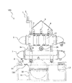
- FIG. 1 is a left side view of a gravity measuring apparatus according to an embodiment of the present invention
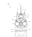
- FIG. 2 is a front view of the gravity measuring apparatus shown in FIG. 1
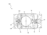
- FIG. 3 is a gravity shown in FIG. It is a bottom view of a measuring device.
- the gravity measurement apparatus 100 mainly includes a main container 6 containing various control boards and the like, and a battery container 7 containing a battery 115 (see FIG. 4) which is a power source for operating the gravity measurement apparatus 100. And the spherical container 10 which accommodated the gravimeter 111 (refer FIG. 4) which performs gravity measurement.
- the gravity measuring apparatus 100 is configured to be able to navigate in water, which will be described in detail later, and is grounded on the bottom of the water to perform gravity measurement using the gravimeter 111.
- the gravity measurement apparatus 100 can be grounded by measuring on the bottom of the seabed such as the seabed, the bottom of the lake, the bottom of the river, etc., an example in the case of landing on the seabed will be described below.
- the main container 6, the battery container 7 and the spherical container 10 are waterproofed so that seawater does not enter inside, and are pressure-processed so as to withstand water pressure.
- the gravimeter 111 is housed in the spherical container 10, and is configured to be held horizontal by, for example, a gimbal mechanism (not shown). Holding the horizontal of the gravimeter 111 ensures that the gravity measured by the gravimeter 111 is gravity in the vertical direction. Although the gravimeter 111 is supported by the gimbal mechanism, the measurement result by the gravimeter 111 may be corrected according to the case where the level can not be maintained completely or there is another external source.
- the spherical container 10 accommodating the gravimeter 111 is fixed to a skid 11 which is a receiving rack, and is provided at the lower center of the gravity measuring apparatus 100.
- a ballast releaser 110, a Doppler type ground speedometer 12, and a CTD 15 are provided in the lower part of the gravity measurement apparatus 100.
- the CTD data is stored, for example, inside the CTD 15 together with the measurement time.
- a wireless LAN antenna 1 is provided on the upper portion of the gravity measurement apparatus 100, and the wireless LAN communication device 103 (see FIG. 4) in the main container 6 communicates data with the outside through the wireless LAN via the wireless LAN antenna 1. It is feasible.
- a GPS antenna 2 is provided on the upper portion of the gravity measurement apparatus 100 adjacent to the wireless LAN antenna 1, and the GPS device 105 (see FIG. 4) in the main container 6 is not suitable via the GPS antenna 2.
- one transmission antenna 3 and four reception antennas 4 used in the acoustic positioning communication device 104 (refer to FIG. 4) in the main container 6 that enables data communication by sound in the upper center of the gravity measurement device 100.
- the wireless LAN communication apparatus 103 can communicate with the outside such as a ship on the sea, for example.
- the gravity measurement device 100 dives into the sea, communication by the wireless LAN communication device 103 becomes difficult. Therefore, in the present embodiment, the gravity measurement device 100 is provided with the acoustic positioning communication device 104, thereby enabling communication between the gravity measurement device 100 in the sea and the outside such as a ship on the sea.
- the gravity measurement device 100 is provided with thrusters 108 (see FIG. 4) that generate a propulsive force so that the gravity measurement device 100 can move in the sea.
- the thruster 108 according to this embodiment is a propeller-like member, and includes two surge thrusters 5a that generate thrust in the front-rear direction, one thruster 5b that generates thrust in the left-right direction, and propulsion in the vertical direction. And two Heaves rasters 5c for generating force.
- a buoyancy material 13 is provided around the main container 6 in the gravity measurement apparatus 100. Further, the gravity measuring apparatus 100 is provided with a ballast (a weight for balancing the buoyancy) not shown, and when all the thrusters 108 are stopped, the gravity measuring apparatus 100 is in a grounded state. Also, when the ballast is released (discarded) by the ballast releaser 110 (see FIG. 4), the gravity measurement device 100 floats to the sea surface by the buoyancy of the buoyancy material 13.
- a ballast a weight for balancing the buoyancy
- the bottom of the battery container 7 of the gravity measurement apparatus 100 is provided with a laser 8 capable of irradiating the bottom with a laser beam, and the bottom of the gravity measurement apparatus 100 can be photographed with the bottom of the laser light irradiated by the laser 8
- a camera 14 is provided.
- a linear laser beam is emitted from the laser 8 to the seabed, and the image thereof is photographed by the camera 14.
- the three-dimensional shape of the seabed can be acquired by a light cutting method.
- the three-dimensional shape of the seabed is obtained by the light cutting method, but the present invention is not limited to this, and any known method may be used.
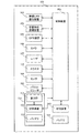
- FIG. 4 is a schematic block diagram of the gravity measuring apparatus shown in FIG.
- the control device 101 of FIG. 4 includes, for example, an arithmetic device called a CPU and an MPU, and is accommodated in the main container 6.
- the operation control of the gravity measurement apparatus 100 is performed by the control device 101.
- the storage device 102 is a storage device such as a RAM or a ROM, includes a non-volatile storage device, and stores programs executed by the control device 101 to operate the gravity measurement device 100 and various data.
- the storage device 102 may store various measurement data in association with the time and position acquired by the GPS device 105.
- the control device 101 may have a clock (not shown), and when the time can not be obtained by the GPS device 105 because it is under the sea, the control device 101 is associated with the time obtained by the clock of the control device 101.
- Various measurement data may be stored in the storage device 102. Further, by previously installing a station (not shown) on the seabed, the relative position of the gravity measurement device 100 to the station can be acquired using the acoustic positioning communication device 104. When the position can not be obtained by the GPS device 105 because it is under the sea, the relative position obtained by the acoustic positioning communication device 104 is stored in the storage device 102 in association with time and various measurement data. It is also good.
- the control device 101 operates according to a program stored in advance in the storage device 102, and controls each part of the gravity measurement device 100.
- the control device 101 can also control each part of the gravity measurement device 100 by remote control according to an operation instruction obtained through the wireless LAN communication device 103 or the acoustic positioning communication device 104.
- the camera 106 includes the camera 14 shown in FIG. 3 and includes other cameras (not shown) (for example, another camera for photographing the seabed, another camera for photographing the periphery of the gravity measurement device 100) It is also good.
- the camera 106 captures an image according to an instruction from the control device 101, sends the captured image (or video) to the control device 101, and the control device 101 receives the image and stores it in the storage device 102.
- the laser 107 includes the laser 8 shown in FIG. 1 and may include another laser (not shown) (for example, a laser different from the laser 8).
- the laser 107 emits a laser beam according to an instruction from the control device 101.
- the camera 106 and the laser 107 may alternatively be sonars (not shown).
- the thruster 108 switches rotation start, rotation stop, rotation direction, and rotation speed of the propeller according to an instruction from the control device 101.
- the directions of the surge thruster 5 a, the sway thruster 5 b, and the heaves raster 5 c are fixed, but may be changed to any direction by an instruction from the control device 101.
- the sensor 109 is a Doppler type ground velocity meter (Doppler Velocity Log, DVL) 12 that measures ground velocity, a fiber optic Gyro (FOG) (not shown) that measures azimuth angular velocity, and a pressure gauge (not shown) that measures water depth. And a posture sensor (not shown), etc., operates according to an instruction from the control device 101, and transmits the measurement result and the detection result to the control device 101.
- a magnetic compass is attached to the attitude sensor and the DVL. Further, by replacing the fiber optic gyro and the attitude sensor with an inertial navigation system (INS), more accurate position and attitude data can be obtained.
- INS inertial navigation system
- a scanning sonar (not shown) is mounted for detecting an obstacle
- a flasher (not shown) and a transponder are provided as a safety measure when operating in the actual sea area. Do.
- the ballast releaser 110 releases (discards) the above-mentioned ballast under the instruction from the controller 101.
- the gravimeter 111 always measures the gravity and transmits the measurement result to the storage device 112.
- the storage device 112 may start storage of the measurement result of gravity and stop storage of the measurement result according to an instruction from the control device 101, or a program stored in advance in the storage device 112. Storage of the measurement result of gravity according to the measurement result may be transmitted to the control device 101. Alternatively, the control device 101 may receive an error or other operation condition during measurement. It may be sent.
- the storage device 112 is, for example, a device called a data logger.
- the battery 115 supplies power to each component of the gravity measurement apparatus 100.
- the gravimeter 111 and the storage device 112 need to be energized at all times (for example, the gravimeter 111 needs to be measured in an environment where the ambient temperature is kept constant). Therefore, the power is supplied from the dedicated battery 113.
- the gravity measuring unit 114 is configured by the gravimeter 111, the storage device 112, and the battery 113.
- FIG. 5 is a flow chart showing an example of the operation of the gravity measuring apparatus shown in FIG.
- the gravity measurement apparatus 100 is placed on a ship or the like, travels on the sea, transported to the area where the gravity measurement is to be performed, and the gravity measurement apparatus 100 is lowered to the sea surface.
- the gravity measuring apparatus 100 can autonomously navigate and hover in the sea by driving the thruster 108, and the thruster 108 is stopped by the buoyancy balance between the gravity of the gravity measuring apparatus 100 and the buoyancy material 13 and the above-described ballast. In the state, it is configured to have negative buoyancy so as to be stable on the seabed.
- the present invention is not limited to this, and neutral buoyancy may be used, and downward thrust may be continued by the heaves raster 5c at the bottom, or, for example, the buoyancy is adjusted by a buoyancy adjuster (not shown). You may
- the control device 101 executes a program stored in advance in the storage device 102, and the processing shown in the flowchart of FIG. 5 is automatically executed.
- remote control via the acoustic positioning communication device 104 is also possible.
- the control device 101 analyzes the bottom image taken by the camera 106 based on the measurement result by the sensor 109 and the detection result, and also on the basis of the positioning result by the acoustic positioning communication device 104. Then, the thruster 108 is driven so as to dive and reach a predetermined landing area (steps S-0 and S-1). One or more landing areas are stored in advance in the storage device 102, one of the landing areas is selected, and gravity measurement is sequentially performed on each landing area as described later.
- the control device 101 irradiates the bottom of the line with the laser light with the laser 8 and photographs the bottom of the sea irradiated with the laser light with the camera 14.
- the three-dimensional shape of the seabed is acquired, for example, by light cutting using the photographed image (step S-2).
- the seabed topography is measured by the sonar, and a three-dimensional seabed shape is acquired based on the measurement result by the sonar. You may do so.
- the control device 101 refers to the three-dimensional shape of the seabed acquired in step S-2, and determines a landing point, that is, a landing target position (step S-3).
- a landing target position a gravity measurement apparatus 100 with small unevenness and small inclination (at an angle as close to horizontal as possible) in the seabed is selected and determined as a position at which the landing can be performed.
- the control device 101 drives the thruster 108 to land the gravity measurement device 100 at the landing target position (step S-4).
- the gravity measuring apparatus 100 measures the flow direction with the flow meter of the sensor 109 in a state of being stationary with respect to the seabed surface, and faces in the direction opposite to the flow. While maintaining the orientation, for example, while measuring the height from the seabed and the ground speed with the Doppler type ground speed meter 12 of the sensor 109, the thrust of the heaves raster 5c is lowered to descend straight and then stand.
- the thrusters 108 ie, all thrusters of the surge thruster 5a, sway thruster 5b, heaves raster 5c) are stopped.
- the posture sensor of the sensor 109 monitors the posture of the gravity measurement apparatus 100 for a predetermined time (for example, several seconds to several minutes) (step S-5). 5: Yes), the base continues to be fixed, and the gravity measurement with the gravimeter 111 is executed (step S-6). The measurement results are stored in the storage devices 102 and 112.
- step S-5 If there is a change in posture at step S-5 (step S-5: No), the process returns to step S-1 and starts from the selection of the landing target position.
- step S-6 it is determined whether or not the gravity measurement in all the landing areas stored in advance in the storage device 102 is completed (step S-7). (Step S-7: No) Returning to step S-1, the gravity measurement in the new landing area is performed. If it is completed (Step S-7: Yes), it will progress to Step S-8 and will rise to the sea level. At this time, in the control device 101, the flying speed can be increased by driving the thruster and releasing the ballast by the ballast releaser 110 to increase the buoyancy and make it a positive buoyancy.
- FIG. 6 is a diagram for explaining an example of the operation of the gravity measuring apparatus shown in FIG.
- the example of FIG. 6 shows the case where the gravity measurement apparatus 100 performs gravity measurement at point A, point B, point C and point D.
- the gravity measurement apparatus 100 first executes the processing of steps S-1 to S-7 of FIG. 5 at point A, and then performs the processing of steps S-1 to S-7 of FIG. Then, the processing of steps S-1 to S-7 in FIG. 5 is performed at point C, and the processing of steps S-1 to S-7 in FIG. As blockage measurement, the process returns to the point A (starting point), the processes of steps S-1 to S-7 of FIG. 5 are executed at the point A, and then the surface is floated to the sea surface by the process of step S-8 of FIG.
- the gravity at points B and C is greater than the gravity at points A and D, and a dense substance is observed from point B to point C compared to the surrounding area. It is conceivable that (for example, a hydrothermal deposit or the like) is present.
- the present embodiment by acquiring the three-dimensional shape of the seabed and determining the landing target position based on the three-dimensional shape of the seabed, it is possible to safely and stably land the gravity measuring device, Measurement of gravity at
- gravity measurement can be performed on the seabed, and gravity can be measured with high accuracy as compared to the case of measurement in the air, the sea, or the sea.
- a series of gravity measurement processing can be performed by operating according to a program stored in advance in the storage device 102, for example, it is necessary to make a wired connection with a ship at sea. It is also possible to measure gravity at deeper seabeds.
- a gravity measuring device e.g., a gravity measuring device 100 capable of autonomous navigation and hovering in the water and measuring the gravity on the bottom of the water,
- a gravity measurement unit for example, a gravity measurement unit 114) that measures the gravity;
- a propulsive force generation unit for example, thruster 108) that generates a propulsive force so that the gravity measurement device can move in water;
- a laser eg, laser 107) for irradiating the bottom of the water with a laser beam;
- a camera for example, a camera 106) for photographing the bottom of the water irradiated with laser light by the laser;
- a bottom shape acquisition unit for example, the control device 101
- a landing position determination unit for example, the control device 101) that determines a landing target position of the gravity measurement device based on the water bottom shape acquired by the water bottom shape acquisition unit;
- a landing control unit for example, the control
- a posture sensor for example, a posture sensor included in the sensor 109 that detects a change in posture of the gravity measurement device; Equipped with Because it was a gravity measuring device, which was characterized by -It is possible to provide a gravity measurement apparatus capable of stably performing unmanned gravity measurement at the bottom of the water.
- the present invention 2.
- a gravity measuring device capable of autonomous navigation and hovering in the water and measuring the gravity on the bottom of the water, A gravity measurement unit that measures gravity, A propulsive force generation unit that generates a propulsive force so that the gravity measurement device can move in water;
- a sonar that measures underwater topography, A bottom shape acquisition unit that acquires a three-dimensional bottom shape based on the measurement result by the sonar;
- a landing position determination unit that determines a landing target position of the gravity measurement device based on the water bottom shape acquired by the water bottom shape acquisition unit;
- a landing control unit for controlling the propulsive force generation unit to reach the landing target position determined by the landing position determination unit, and landing the gravity measurement device at the landing target position;
- An attitude sensor that detects an attitude change of the gravity measuring device; Equipped with Because it was a gravity measuring device, which was characterized by -It is possible to provide a gravity measurement apparatus capable of stably performing unmanned gravity measurement at the bottom of the water.
- the present invention 3. 1. Or 2.
- the landing position determination unit changes the landing target position and determines a new landing target position when there is a change in the posture detected by the posture sensor in a state where the gravity measurement device is in the bottom position.
- a gravity measuring device characterized by
Landscapes
- Engineering & Computer Science (AREA)
- General Physics & Mathematics (AREA)
- Physics & Mathematics (AREA)
- Mechanical Engineering (AREA)
- Ocean & Marine Engineering (AREA)
- Radar, Positioning & Navigation (AREA)
- Aviation & Aerospace Engineering (AREA)
- General Life Sciences & Earth Sciences (AREA)
- Geophysics (AREA)
- Life Sciences & Earth Sciences (AREA)
- Remote Sensing (AREA)
- Chemical & Material Sciences (AREA)
- Combustion & Propulsion (AREA)
- Length Measuring Devices By Optical Means (AREA)
- Length Measuring Devices Characterised By Use Of Acoustic Means (AREA)
- Geophysics And Detection Of Objects (AREA)
- Measurement Of Velocity Or Position Using Acoustic Or Ultrasonic Waves (AREA)
Abstract
水中を自律航行およびホバリング可能であり、水底に着底して重力を測定する重力測定装置であって、重力を測定する重力測定部と、前記重力測定装置が水中移動可能なように推進力を発生する推進力発生部と、水底にレーザ光を照射するレーザと、前記レーザによりレーザ光を照射した水底を撮影するカメラと、前記カメラにより撮影した画像に基づいて三次元の水底形状を取得する水底形状取得部と、前記水底形状取得部により取得した水底形状に基づいて前記重力測定装置の着底目標位置を決定する着底位置決定部と、前記着底位置決定部により決定した着底目標位置に到達するよう前記推進力発生部を制御し、前記重力測定装置を該着底目標位置に着底させる着底制御部と、前記重力測定装置の姿勢の変動を検出する姿勢センサとを備える。
Description
本発明は、重力測定装置に関し、詳しくは、例えば海底において重力を測定する重力測定装置に関する。
重力は、測定地点から地球の中心までの距離や地下の密度構造などに応じて、その大きさがわずかながら異なることが知られている。これを利用し、重力を測定することによって地下密度構造を調査することが知られている。
特許文献1に記載の発明では、ヘリコプターのような航行体に重力計を搭載し、航行体によって飛行しながら重力を測定する重力測定装置を開示している。
特許文献1に記載の重力測定装置では、DGPSによって現在位置を測定し、飛行しながら重力測定を行うことを可能としている。しかしながら、この重力測定装置では、重力計を搭載した航行体によって飛行するものであるため、例えば海底や湖底や川底といった水底における重力測定には適さないという問題があった。
例えば海底において重力を測定することにより、海底の地下の鉱床などを高い精度で探査することができ、海底資源の発見に寄与することができるため、海底における重力測定が重要であると考えられる。
本発明は、水底における重力測定を無人無索で安定して実行可能な重力測定装置を提供することを目的とする。
本発明は上記の目的を達成するために、水中を自律航行およびホバリング可能であり、水底に着底して重力を測定する重力測定装置であって、重力を測定する重力測定部と、前記重力測定装置が水中移動可能なように推進力を発生する推進力発生部と、水底にレーザ光を照射するレーザと、前記レーザによりレーザ光を照射した水底を撮影するカメラと、前記カメラにより撮影した画像に基づいて三次元の水底形状を取得する水底形状取得部と、前記水底形状取得部により取得した水底形状に基づいて前記重力測定装置の着底目標位置を決定する着底位置決定部と、前記着底位置決定部により決定した着底目標位置に到達するよう前記推進力発生部を制御し、前記重力測定装置を該着底目標位置に着底させる着底制御部と、前記重力測定装置の姿勢の変動を検出する姿勢センサと、を備えた、ことを特徴とする。
また本発明は、水中を自律航行およびホバリング可能であり、水底に着底して重力を測定する重力測定装置であって、重力を測定する重力測定部と、前記重力測定装置が水中移動可能なように推進力を発生する推進力発生部と、水底地形を計測するソーナーと、前記ソーナーによる計測結果に基づいて三次元の水底形状を取得する水底形状取得部と、前記水底形状取得部により取得した水底形状に基づいて前記重力測定装置の着底目標位置を決定する着底位置決定部と、前記着底位置決定部により決定した着底目標位置に到達するよう前記推進力発生部を制御し、前記重力測定装置を該着底目標位置に着底させる着底制御部と、前記重力測定装置の姿勢の変動を検出する姿勢センサと、を備えた、ことを特徴とする。
本発明によれば、水底における重力測定を無人無索で安定して実行可能な重力測定装置を提供することができる。
以下、本発明の実施形態について、図面を参照しながら詳細に説明する。
図1は、本発明の一実施形態に係る重力測定装置の左側面図であり、図2は、図1に示した重力測定装置の正面図であり、図3は、図1に示した重力測定装置の底面図である。
本実施形態の重力測定装置100は、主に、各種制御基板等を収容したメイン容器6と、重力測定装置100を動作させる電源であるバッテリ115(図4参照)を収容したバッテリ容器7と、重力測定を行う重力計111(図4参照)を収容した球形容器10と、を有して構成される。重力測定装置100は、詳しくは後述するが水中を航行可能に構成され、水底に着底して重力計111により重力測定を行う。なお、重力測定装置100は、海底、湖底、川底などの水底に着底して重力を測定可能であるが、以下では、海底に着底する場合の例について説明を行う。メイン容器6、バッテリ容器7および球形容器10は内部に海水が進入しないように防水加工がされ、また、水圧に耐えられるよう耐圧加工がされている。
重力計111は、球形容器10に収容され、例えば、不図示のジンバル機構によって水平が保持されるように構成されている。重力計111の水平が保持されることで、重力計111が測定する重力が鉛直方向の重力であることが担保される。なお、重力計111はジンバル機構に支持されているが、完全に水平が維持できない場合やその他の外因がある場合には、重力計111による測定結果をそれに応じて補正する構成としてもよい。
重力計111を収容した球形容器10は、荷受け台であるスキッド11に固定され、重力測定装置100の下部中央に設けられる。また、重力測定装置100の下部には、バラストリリーサ110、ドップラ式対地速度計12、CTD15、を設けている。なお、CTD15は、周囲の海水の電気伝導度(Conductivity)(=塩分)、温度(Temperature)、深度(Depth)を測る装置であり、このCTD15で測定したCTDデータから、海水の密度と正確な深度を計算で求めることができる。このCTDデータを用いることで、重力計111で測定した重力の補正を精密に行うことができる。このCTDデータは例えば測定時刻とともにCTD15の内部に保存される。
重力測定装置100の上部には、無線LANアンテナ1を設けており、この無線LANアンテナ1を介し、メイン容器6内の無線LAN通信装置103(図4参照)によって外部と無線LANによるデータ通信を実行可能である。
また、重力測定装置100の上部には、無線LANアンテナ1と隣接してGPSアンテナ2を設けており、このGPSアンテナ2を介してメイン容器6内のGPS装置105(図4参照)が、不図示のGPS衛星からのGPS信号を受信することにより、水面での重力測定装置100の位置を特定可能にしている。
さらに、重力測定装置100の上部中央には、音響によりデータ通信を可能とするメイン容器6内の音響測位通信装置104(図4参照)で用いる一本の送信アンテナ3および4本の受信アンテナ4を設けている。重力測定装置100が海上にある場合には、無線LAN通信装置103によって、例えば海上の船などの外部と通信が可能である。しかし、重力測定装置100が海中に潜ると、無線LAN通信装置103による通信は困難になる。そこで本実施形態では、重力測定装置100に音響測位通信装置104を設け、これにより海中の重力測定装置100と例えば海上の船などの外部とで通信可能にしている。
重力測定装置100は、重力測定装置100が海中で移動可能なように推進力を発生させるスラスタ108(図4参照)を設けている。本実施形態のスラスタ108は、プロペラ状の部材であって、前後方向の推進力を発生させる二つのサージスラスタ5aと、左右方向の推進力を発生させる一つのスウェイスラスタ5bと、上下方向の推進力を発生させる二つのヒーブスラスタ5cと、を有する。これら二つのサージスラスタ5a、一つのスウェイスラスタ5bおよび二つのヒーブスラスタ5cのプロペラの回転開始、回転停止、回転方向および回転速度を切り替えることによって、重力測定装置100を自在に移動させることが可能である。
重力測定装置100においてメイン容器6の周囲には浮力材13を設けている。また、重力測定装置100には不図示のバラスト(浮力のバランスを取るための重り)を設けており、スラスタ108をすべて停止させた場合には、重力測定装置100は着底した状態となる。また、バラストリリーサ110(図4参照)によってバラストをリリース(投棄)すると、重力測定装置100は浮力材13の浮力によって海面に浮き上がる。
重力測定装置100のバッテリ容器7の下部には、海底にレーザ光を照射可能なレーザ8を設けており、重力測定装置100の底面には、レーザ8でレーザ光を照射した海底を撮影可能なカメラ14を設けている。レーザ8からは線状のレーザ光を海底に照射し、その画像をカメラ14で撮影し、例えば光切断法により、海底の三次元形状を取得することができる。本実施形態では光切断法によって海底の三次元形状を取得するようにしているが本発明はこれに限られるものではなく、既知の如何なる手法を用いるものであってもよい。
図4は、図1に示した重力測定装置の概略ブロック図である。
図4の制御装置101は、例えば、CPU、MPUと呼ばれる演算装置から成り、メイン容器6に収容される。重力測定装置100の動作制御は、この制御装置101によって行われる。記憶装置102は、RAM、ROMといった記憶装置であり、不揮発性記憶装置を含み、重力測定装置100を動作させるために制御装置101で実行するプログラムや、各種データを記憶する。記憶装置102には、GPS装置105によって取得した時刻や位置に対応づけて各種測定データを記憶しておくものであってもよい。また、制御装置101は、不図示の時計を有するものであってもよく、海中のためGPS装置105によって時刻が得られない場合には、この制御装置101の時計によって取得した時刻に対応づけて各種測定データを記憶装置102に記憶しておくものであってもよい。また、不図示のステーションを海底に予め設置しておくことにより、音響測位通信装置104を用いて、そのステーションに対する重力測定装置100の相対位置を取得することができる。海中のためGPS装置105によって位置が得られない場合には、この音響測位通信装置104によって得た相対位置を、時刻や各種測定データに対応づけて記憶装置102に記憶しておくものであってもよい。
制御装置101は、記憶装置102に予め記憶されたプログラムにより動作し、重力測定装置100の各部の制御を行う。また、制御装置101は、無線LAN通信装置103や音響測位通信装置104を介して得た動作指示により遠隔操作により、重力測定装置100の各部の制御を行うこともできる。
カメラ106は、図3に示したカメラ14を含み、不図示の他のカメラ(例えば、海底を撮影する他のカメラ、重力測定装置100の周囲を撮影する他のカメラ)を含むものであってもよい。カメラ106は、制御装置101からの指示で撮影を行い、撮影した画像(あるいは映像)を制御装置101に送り、これを受けた制御装置101は記憶装置102に記憶する。
レーザ107は、図1に示したレーザ8を含み、不図示の他のレーザ(例えば、レーザ8とは異なるレーザ)を含むものであってもよい。レーザ107は、制御装置101からの指示でレーザ光の照射を行う。
カメラ106およびレーザ107は、代わりに不図示のソーナーであってもよい。
スラスタ108は、制御装置101からの指示でプロペラの回転開始、回転停止、回転方向、回転速度の切り替えを行う。なお、本実施形態では、サージスラスタ5a、スウェイスラスタ5b、ヒーブスラスタ5cのそれぞれの向きは固定であるが、制御装置101からの指示で任意の向きに変えることができるようにしてもよい。
センサ109は、対地速度を計測するドップラ式対地速度計(Doppler Velocity Log, DVL)12、方位角速度を計る光ファイバジャイロ(Fiber Optic Gyro, FOG)(不図示)、水深を測る圧力計(不図示)、流速計(不図示)、姿勢センサ(不図示)等を含み、制御装置101からの指示で動作し、計測結果、検知結果を制御装置101に送信する。なお、姿勢センサおよびDVLには磁気コンパスを付属している。また、光ファイバジャイロと姿勢センサを慣性航法装置(Inertial Navigation System,INS)に換装することで、より高精度の位置・姿勢データを得ることができる。また、センサ109としては、この他、障害物探知用にスキャニングソーナー(不図示)を搭載し、さらに、実海域での運用時には、安全対策としてフラッシャ(不図示)とトランスポンダ(不図示)を装備する。
バラストリリーサ110は、制御装置101からの指示で上述のバラストをリリース(投棄)する。
重力計111は、常に重力を測定し、測定結果を記憶装置112に送信する。なお、記憶装置112は、制御装置101からの指示で、重力の測定結果の記憶を開始し、測定結果の記憶を停止するものであってもよいし、記憶装置112に予め記憶してあるプログラムに応じて重力の測定結果の記憶を行うものであってもよいし、測定結果を制御装置101に送信するものであってもよいし、測定時のエラーやその他の動作状況を制御装置101に送信するものであってもよい。記憶装置112は、例えばデータロガーと呼ばれる装置である。
バッテリ115は、重力測定装置100の各構成に電源を供給する。ただし、重力計111と記憶装置112には常時通電が必要(例えば、重力計111は周辺温度を一定に保った環境で測定する必要があり、重力計111を収容する恒温槽のために常時通電が必要である。)なため専用のバッテリ113から電源を供給する。重力計111と記憶装置112とバッテリ113とで重力測定部114を構成する。
図5は、図1に示した重力測定装置の動作の一例を示すフローチャートである。
まず、重力測定装置100を船などに載せて海上を進み、重力測定を実施する地域まで海上を運び、重力測定装置100を海面に降ろす。なお、重力測定装置100は、スラスタ108を駆動することで海中を自律航行およびホバリング可能であり、重力測定装置100の自重と浮力材13と上述のバラストとの浮力バランスにより、スラスタ108を停止した状態では、海底で安定するように、マイナス浮力となるよう構成されている。なお、本発明はこれに限られるものではなく、中性浮力とし、着底時にはヒーブスラスタ5cにより下向きの推力を継続させるようにしてもよいし、例えば浮力調整装置(不図示)により浮力を調整してもよい。
その後、例えば、重力測定装置100が海上にある場合は船上の操作者が不図示の端末装置等を操作して、無線LANアンテナ1および無線LAN通信装置103を介して重力測定装置100の遠隔操作を行い、図5の処理の実行を指示する。これを受けた重力測定装置100では、記憶装置102に予め記憶してあるプログラムが制御装置101で実行され、図5のフローチャートに示す処理が自動で実行される。また、重力測定装置100が海中にある場合には音響測位通信装置104を介しての遠隔操作も可能である。
制御装置101は、センサ109による計測結果、検知結果に基づき、また、音響測位通信装置104による測位結果に基づき、また、カメラ106で撮影した海底画像を分析し、重力測定装置100が海底付近まで潜航し、予め定めた着底エリアに到達するよう、スラスタ108を駆動する(ステップS-0、S-1)。着底エリアは、一つまたは複数を記憶装置102に予め記憶しておき、各着底エリアのうちの一を選択し、後述するようにそれぞれの着底エリアで順に重力の測定を行う。
続いて、重力測定装置100が着底エリアに到達したならば、制御装置101は、レーザ8でライン状のレーザ光を海底に照射するとともに、そのレーザ光を照射した海底をカメラ14で撮影し、その撮影画像を用いて、例えば光切断法により海底の三次元形状を取得する(ステップS-2)。なお、レーザ8およびカメラ14の代わりにソーナーを設けた構成の場合には、このステップS-2では、ソーナーによって海底地形を計測し、ソーナーによる計測結果に基づいて三次元の海底形状を取得するようにしてもよい。
続いて、制御装置101では、ステップS-2で取得した海底の三次元形状を参照し、着底地点すなわち着底目標位置を決定する(ステップS-3)。この着底目標位置としては、海底のうち凹凸が少なく、且つ傾斜の小さい(できるだけ水平に近い角度の)重力測定装置100が着底可能な位置を選択し、決定する。
着底目標位置を決定したならば、制御装置101では、スラスタ108を駆動し、重力測定装置100をその着底目標位置に着底させる(ステップS-4)。例えば、重力測定装置100は海底面に対して静止した状態でセンサ109の流速計により流向を計測し、流れに正対する方位を向く。その方位を維持したまま、例えばセンサ109のドップラ式対地速度計12により海底からの高度と対地速度を計測しながら、ヒーブスラスタ5cの推力を下げることでまっすぐ降下し、そのまま着底する。着底完了したならば、スラスタ108(すなわちサージスラスタ5a、スウェイスラスタ5b、ヒーブスラスタ5cの全てのスラスタ)を停止する。
その後、制御装置101では、センサ109の姿勢センサにより、一定時間(例えば、数秒から数分)重力測定装置100の姿勢を監視し(ステップS-5)、姿勢の変動がない場合(ステップS-5:Yes)には、そのまま着底を継続し、重力計111による重力測定を実行する(ステップS-6)。測定結果は、記憶装置102や112に記憶される。
ステップS-5で姿勢の変動がある場合(ステップS-5:No)には、ステップS-1に戻り、着底目標位置の選定からやり直す。
ステップS-6で重力測定を終了したならば、記憶装置102に予め記憶してある全ての着底エリアでの重力測定が完了したかを判断し(ステップS-7)、完了していなければ(ステップS-7:No)、ステップS-1に戻り、新たな着底エリアでの重力測定を実施する。完了したならば(ステップS-7:Yes)、ステップS-8に進み、海面に浮上する。このとき、制御装置101では、スラスタを駆動するとともに、バラストリリーサ110によってバラストをリリースして浮力を上昇させプラス浮力とすることで、浮上速度を速めることができる。
図6は、図1に示した重力測定装置の動作の一例を説明する図である。この図6の例では、重力測定装置100が、A地点、B地点、C地点およびD地点で重力測定を行う場合を示している。
この例では、重力測定装置100は、まずA地点で図5のステップS-1~S-7の処理を実行し、続いてB地点で図5のステップS-1~S-7の処理を実行し、続いてC地点で図5のステップS-1~S-7の処理を実行し、続いてD地点で図5のステップS-1~S-7の処理を実行し、最後に、閉塞測定として、A地点(起点)に戻り、A地点で図5のステップS-1~S-7の処理を実行し、その後、図5のステップS-8の処理で海面に浮上する。
A~D地点での重力測定の結果を比較すると、AおよびD地点での重力よりも、BおよびC地点での重力が大きく、B地点からC地点に亘り周囲と比較して高密度な物質(例えば熱水鉱床等)が存在することが考えられる。
本実施形態によれば、海底の三次元形状を取得し、この海底の三次元形状に基づいて着底目標位置を決定することで、重力測定装置の安全且つ安定な着底を可能とし、海底での重力測定を可能とすることができる。
また本実施形態によれば、海底で重力測定を実施することができ、空中、海上、海中で測定する場合と比べて高い精度で重力を測定することができる。
また本実施形態によれば、記憶装置102に予め記憶してあるプログラムによって動作し、一連の重力測定処理を実行することができるので、例えば、海上の船と有線で繋いだ状態にする必要がなく、より深い海底での重力測定も可能である。
<付記1>
なお、本発明は、
1.
水中を自律航行およびホバリング可能であり、水底に着底して重力を測定する重力測定装置(例えば、重力測定装置100)であって、
重力を測定する重力測定部(例えば、重力測定部114)と、
前記重力測定装置が水中移動可能なように推進力を発生する推進力発生部(例えば、スラスタ108)と、
水底にレーザ光を照射するレーザ(例えば、レーザ107)と、
前記レーザによりレーザ光を照射した水底を撮影するカメラ(例えば、カメラ106)と、
前記カメラにより撮影した画像に基づいて三次元の水底形状を取得する水底形状取得部(例えば、制御装置101)と、
前記水底形状取得部により取得した水底形状に基づいて前記重力測定装置の着底目標位置を決定する着底位置決定部(例えば、制御装置101)と、
前記着底位置決定部により決定した着底目標位置に到達するよう前記推進力発生部を制御し、前記重力測定装置を該着底目標位置に着底させる着底制御部(例えば、制御装置101)と、
前記重力測定装置の姿勢の変動を検出する姿勢センサ(例えば、センサ109に含まれる姿勢センサ)と、
を備えた、
ことを特徴とする重力測定装置、としたので、
・水底における重力測定を無人無索で安定して実行可能な重力測定装置を提供することができる。
なお、本発明は、
1.
水中を自律航行およびホバリング可能であり、水底に着底して重力を測定する重力測定装置(例えば、重力測定装置100)であって、
重力を測定する重力測定部(例えば、重力測定部114)と、
前記重力測定装置が水中移動可能なように推進力を発生する推進力発生部(例えば、スラスタ108)と、
水底にレーザ光を照射するレーザ(例えば、レーザ107)と、
前記レーザによりレーザ光を照射した水底を撮影するカメラ(例えば、カメラ106)と、
前記カメラにより撮影した画像に基づいて三次元の水底形状を取得する水底形状取得部(例えば、制御装置101)と、
前記水底形状取得部により取得した水底形状に基づいて前記重力測定装置の着底目標位置を決定する着底位置決定部(例えば、制御装置101)と、
前記着底位置決定部により決定した着底目標位置に到達するよう前記推進力発生部を制御し、前記重力測定装置を該着底目標位置に着底させる着底制御部(例えば、制御装置101)と、
前記重力測定装置の姿勢の変動を検出する姿勢センサ(例えば、センサ109に含まれる姿勢センサ)と、
を備えた、
ことを特徴とする重力測定装置、としたので、
・水底における重力測定を無人無索で安定して実行可能な重力測定装置を提供することができる。
また本発明は、
2.
水中を自律航行およびホバリング可能であり、水底に着底して重力を測定する重力測定装置であって、
重力を測定する重力測定部と、
前記重力測定装置が水中移動可能なように推進力を発生する推進力発生部と、
水底地形を計測するソーナーと、
前記ソーナーによる計測結果に基づいて三次元の水底形状を取得する水底形状取得部と、
前記水底形状取得部により取得した水底形状に基づいて前記重力測定装置の着底目標位置を決定する着底位置決定部と、
前記着底位置決定部により決定した着底目標位置に到達するよう前記推進力発生部を制御し、前記重力測定装置を該着底目標位置に着底させる着底制御部と、
前記重力測定装置の姿勢の変動を検出する姿勢センサと、
を備えた、
ことを特徴とする重力測定装置、としたので、
・水底における重力測定を無人無索で安定して実行可能な重力測定装置を提供することができる。
2.
水中を自律航行およびホバリング可能であり、水底に着底して重力を測定する重力測定装置であって、
重力を測定する重力測定部と、
前記重力測定装置が水中移動可能なように推進力を発生する推進力発生部と、
水底地形を計測するソーナーと、
前記ソーナーによる計測結果に基づいて三次元の水底形状を取得する水底形状取得部と、
前記水底形状取得部により取得した水底形状に基づいて前記重力測定装置の着底目標位置を決定する着底位置決定部と、
前記着底位置決定部により決定した着底目標位置に到達するよう前記推進力発生部を制御し、前記重力測定装置を該着底目標位置に着底させる着底制御部と、
前記重力測定装置の姿勢の変動を検出する姿勢センサと、
を備えた、
ことを特徴とする重力測定装置、としたので、
・水底における重力測定を無人無索で安定して実行可能な重力測定装置を提供することができる。
また本発明は、
3.
1.または2.に記載の重力測定装置において、
前記着底位置決定部は、前記重力測定装置が着底した状態で、前記姿勢センサにより検出した姿勢に変動がある場合、着底目標位置を変更し、新たな着底目標位置を決定する、
ことを特徴とする重力測定装置、とした。
3.
1.または2.に記載の重力測定装置において、
前記着底位置決定部は、前記重力測定装置が着底した状態で、前記姿勢センサにより検出した姿勢に変動がある場合、着底目標位置を変更し、新たな着底目標位置を決定する、
ことを特徴とする重力測定装置、とした。
本発明の態様は、上述した個々の実施例に限定されるものではなく、個々の実施例の各要素のいかなる組合せも本発明に含み、また、当業者が想到しうる種々の変形も含むものであり、本発明の効果も上述した内容に限定されない。すなわち、特許請求の範囲に規定された内容およびその均等物から導き出される本発明の概念的な思想と趣旨を逸脱しない範囲で種々の追加、変更および部分的削除が可能である。
1…無線LANアンテナ、2…GPSアンテナ、3…送信アンテナ、4…受信アンテナ、5a…サージスラスタ、5b…スウェイスラスタ、5c…ヒーブスラスタ、6…メイン容器、7…バッテリ容器、8…レーザ、10…球形容器、11…スキッド、12…ドップラ式対地速度計、13…浮力材、14…カメラ、15…CTD、110…バラストリリーサ
Claims (3)
- 水中を自律航行およびホバリング可能であり、水底に着底して重力を測定する重力測定装置であって、
重力を測定する重力測定部と、
前記重力測定装置が水中移動可能なように推進力を発生する推進力発生部と、
水底にレーザ光を照射するレーザと、
前記レーザによりレーザ光を照射した水底を撮影するカメラと、
前記カメラにより撮影した画像に基づいて三次元の水底形状を取得する水底形状取得部
と、
前記水底形状取得部により取得した水底形状に基づいて前記重力測定装置の着底目標位置を決定する着底位置決定部と、
前記着底位置決定部により決定した着底目標位置に到達するよう前記推進力発生部を制御し、前記重力測定装置を該着底目標位置に着底させる着底制御部と、
前記重力測定装置の姿勢の変動を検出する姿勢センサと、
を備えた、
ことを特徴とする重力測定装置。 - 水中を自律航行およびホバリング可能であり、水底に着底して重力を測定する重力測定装置であって、
重力を測定する重力測定部と、
前記重力測定装置が水中移動可能なように推進力を発生する推進力発生部と、
水底地形を計測するソーナーと、
前記ソーナーによる計測結果に基づいて三次元の水底形状を取得する水底形状取得部と、
前記水底形状取得部により取得した水底形状に基づいて前記重力測定装置の着底目標位置を決定する着底位置決定部と、
前記着底位置決定部により決定した着底目標位置に到達するよう前記推進力発生部を制御し、前記重力測定装置を該着底目標位置に着底させる着底制御部と、
前記重力測定装置の姿勢の変動を検出する姿勢センサと、
を備えた、
ことを特徴とする重力測定装置。 - 請求項1または2に記載の重力測定装置において、
前記着底位置決定部は、前記重力測定装置が着底した状態で、前記姿勢センサにより検出した姿勢に変動がある場合、着底目標位置を変更し、新たな着底目標位置を決定する、
ことを特徴とする重力測定装置。
Applications Claiming Priority (2)
| Application Number | Priority Date | Filing Date | Title |
|---|---|---|---|
| JP2016-166497 | 2016-08-29 | ||
| JP2016166497A JP6723111B2 (ja) | 2016-08-29 | 2016-08-29 | 重力測定装置 |
Publications (1)
| Publication Number | Publication Date |
|---|---|
| WO2018043006A1 true WO2018043006A1 (ja) | 2018-03-08 |
Family
ID=61309144
Family Applications (1)
| Application Number | Title | Priority Date | Filing Date |
|---|---|---|---|
| PCT/JP2017/027945 Ceased WO2018043006A1 (ja) | 2016-08-29 | 2017-08-01 | 重力測定装置 |
Country Status (2)
| Country | Link |
|---|---|
| JP (1) | JP6723111B2 (ja) |
| WO (1) | WO2018043006A1 (ja) |
Cited By (1)
| Publication number | Priority date | Publication date | Assignee | Title |
|---|---|---|---|---|
| WO2021253487A1 (zh) * | 2020-06-17 | 2021-12-23 | 东南大学 | 水下导航与重力测量一体化系统 |
Families Citing this family (2)
| Publication number | Priority date | Publication date | Assignee | Title |
|---|---|---|---|---|
| JP7280799B2 (ja) * | 2019-10-10 | 2023-05-24 | 株式会社フジタ | 水中測定装置 |
| CN114670996B (zh) * | 2022-05-31 | 2022-08-23 | 中国海洋大学 | 三体水下机器人 |
Citations (1)
| Publication number | Priority date | Publication date | Assignee | Title |
|---|---|---|---|---|
| US20100153050A1 (en) * | 2008-11-11 | 2010-06-17 | Zumberge Mark A | Autonomous Underwater Vehicle Borne Gravity Meter |
-
2016
- 2016-08-29 JP JP2016166497A patent/JP6723111B2/ja active Active
-
2017
- 2017-08-01 WO PCT/JP2017/027945 patent/WO2018043006A1/ja not_active Ceased
Patent Citations (1)
| Publication number | Priority date | Publication date | Assignee | Title |
|---|---|---|---|---|
| US20100153050A1 (en) * | 2008-11-11 | 2010-06-17 | Zumberge Mark A | Autonomous Underwater Vehicle Borne Gravity Meter |
Non-Patent Citations (3)
| Title |
|---|
| KINSEY, JAMES C. ET AL.: "Toward High-Spatial Resolution Gravity Surveying of the Mid-Ocean Ridges with Autonomous Underwater Vehicles", OCEANS 2008, September 2008 (2008-09-01), pages 1 - 10, XP031482999 * |
| MAKI ET AL: "Autonomous Underwater Vehicle "Tri-Dog 1"", JOURNAL OF THE JAPAN INSTITUTE OF MARINE ENGINEERING, vol. 43, no. 4, 2008, pages 73 - 76, XP055604208 * |
| MAKI: "Maps for Underwater Vehicles", JOURNAL OF THE ROBOTICS SOCIETY OF JAPAN, vol. 33, no. 10, 2015, pages 766 - 772, XP055604215 * |
Cited By (1)
| Publication number | Priority date | Publication date | Assignee | Title |
|---|---|---|---|---|
| WO2021253487A1 (zh) * | 2020-06-17 | 2021-12-23 | 东南大学 | 水下导航与重力测量一体化系统 |
Also Published As
| Publication number | Publication date |
|---|---|
| JP6723111B2 (ja) | 2020-07-15 |
| JP2018036055A (ja) | 2018-03-08 |
Similar Documents
| Publication | Publication Date | Title |
|---|---|---|
| US11072405B2 (en) | Autonomous underwater survey apparatus and system | |
| JP6761216B2 (ja) | 水中航走体の経路設定方法、それを用いた水中航走体の最適制御方法及び水中航走体並びに移動体の経路設定方法 | |
| JP7022559B2 (ja) | 無人航空機の制御方法および無人航空機の制御用プログラム | |
| KR101804184B1 (ko) | 드론을 이용한 연안지형 조사장치 | |
| JP7086144B2 (ja) | 移動体、探査測量装置および探査測量方法 | |
| JP6556516B2 (ja) | 海洋探査装置及び海洋探査方法 | |
| NO339088B1 (no) | Autonomt styringsutstyr for havbunnen og fremgangsmåte for innsamling av seismikkdata | |
| AU2007313463A1 (en) | System and method for determining the position of an underwater vehicle | |
| CN116997508A (zh) | 水上中继机与水中航行体的连结系统及其运用方法 | |
| KR101987655B1 (ko) | 수중 지형 측정용 무인 보트 | |
| CA3061547A1 (en) | Navigation system for underwater vehicles | |
| JP6723111B2 (ja) | 重力測定装置 | |
| JP2020049981A (ja) | 無人航空機 | |
| JP2020118641A (ja) | マルチコプター | |
| US8297162B2 (en) | Method and a device for identifying and neutralizing an undersea mine | |
| JP7668510B2 (ja) | 水中航走体の自己位置推定誤差補正方法及び水中航走体の自己位置推定誤差補正システム | |
| Cruz et al. | Cooperative deep water seafloor mapping with heterogeneous robotic platforms | |
| JP7376780B2 (ja) | 飛行制御システム、飛行制御装置、飛行体、及び飛行制御方法 | |
| KR20210147543A (ko) | 수중드론의 운항시스템 및 운항방법 | |
| US20230273021A1 (en) | Detection system, suspended device, and detection method | |
| JP7333565B1 (ja) | 飛行体および飛行体の制御方法 | |
| JP7325284B2 (ja) | 水底形状測定装置 | |
| US20240308632A1 (en) | Linked system of surface repeater vehicle and underwater vehicle, and operation method therefor | |
| JP7280786B2 (ja) | 水底形状測定装置 | |
| JP7709770B2 (ja) | 水中調査装置 |
Legal Events
| Date | Code | Title | Description |
|---|---|---|---|
| 121 | Ep: the epo has been informed by wipo that ep was designated in this application |
Ref document number: 17846015 Country of ref document: EP Kind code of ref document: A1 |
|
| NENP | Non-entry into the national phase |
Ref country code: DE |
|
| 122 | Ep: pct application non-entry in european phase |
Ref document number: 17846015 Country of ref document: EP Kind code of ref document: A1 |