WO2018042893A1 - 画像形成装置 - Google Patents
画像形成装置 Download PDFInfo
- Publication number
- WO2018042893A1 WO2018042893A1 PCT/JP2017/025287 JP2017025287W WO2018042893A1 WO 2018042893 A1 WO2018042893 A1 WO 2018042893A1 JP 2017025287 W JP2017025287 W JP 2017025287W WO 2018042893 A1 WO2018042893 A1 WO 2018042893A1
- Authority
- WO
- WIPO (PCT)
- Prior art keywords
- bias
- transfer
- toner
- cleaning mode
- image
- Prior art date
- Legal status (The legal status is an assumption and is not a legal conclusion. Google has not performed a legal analysis and makes no representation as to the accuracy of the status listed.)
- Ceased
Links
Images





Classifications
-
- G—PHYSICS
- G03—PHOTOGRAPHY; CINEMATOGRAPHY; ANALOGOUS TECHNIQUES USING WAVES OTHER THAN OPTICAL WAVES; ELECTROGRAPHY; HOLOGRAPHY
- G03G—ELECTROGRAPHY; ELECTROPHOTOGRAPHY; MAGNETOGRAPHY
- G03G15/00—Apparatus for electrographic processes using a charge pattern
- G03G15/14—Apparatus for electrographic processes using a charge pattern for transferring a pattern to a second base
- G03G15/16—Apparatus for electrographic processes using a charge pattern for transferring a pattern to a second base of a toner pattern, e.g. a powder pattern, e.g. magnetic transfer
-
- G—PHYSICS
- G03—PHOTOGRAPHY; CINEMATOGRAPHY; ANALOGOUS TECHNIQUES USING WAVES OTHER THAN OPTICAL WAVES; ELECTROGRAPHY; HOLOGRAPHY
- G03G—ELECTROGRAPHY; ELECTROPHOTOGRAPHY; MAGNETOGRAPHY
- G03G21/00—Arrangements not provided for by groups G03G13/00 - G03G19/00, e.g. cleaning, elimination of residual charge
Definitions
- the present invention relates to an image forming apparatus such as a copying machine, a printer, a facsimile machine, and a multifunction machine having a plurality of these functions.
- an intermediate transfer type image forming apparatus that primarily transfers a toner image formed on a photosensitive drum to an intermediate transfer belt as an image carrier and secondarily transfers the toner image from the intermediate transfer belt to a recording material.
- a transfer roller (secondary transfer outer roller) that is in contact with the outer peripheral surface of the intermediate transfer belt is disposed in the secondary transfer portion for secondary transfer of the toner image to the recording material, and a transfer voltage is applied to the transfer roller. Secondary transfer is performed.
- the transfer roller is provided with an elastic layer on the peripheral surface of the conductive shaft portion, and a conductive agent such as an ionic conductive agent is dispersed in the elastic layer to impart conductivity. Therefore, when the voltage application time to the transfer roller increases due to use, ions in the ionic conductive agent are polarized so as to be biased to one of the roller surface side or the shaft portion side, and the electrical resistance tends to increase. Therefore, in order to suppress an increase in electrical resistance caused by polarization, a voltage is applied from the power supply roller as the power supply rotating body in contact with the surface of the transfer roller to the transfer roller, and the toner is transferred from the intermediate transfer belt to the recording material.
- An image forming apparatus for transferring an image has been proposed (Patent Document 1).
- the toner when the toner adheres from the intermediate transfer belt to the transfer roller, the toner may also adhere to the power supply roller that contacts the transfer roller.
- the toner adheres to the power supply roller unevenness in current flowing from the power supply roller to the transfer roller may occur. Further, the toner attached to the power supply roller may reattach to the transfer roller, and the back surface of the recording material may be soiled.
- a configuration in which a cleaning member is provided on the power supply roller, or a configuration in which the power supply roller is electrostatically cleaned by applying a voltage having the same polarity as the toner to the power supply roller. Can be considered.
- the cleaning member is provided on the power supply roller, it is necessary to install a toner recovery unit, and the size of the image forming apparatus is increased.
- the electrostatic cleaning configuration toner is transferred from the power supply roller to the transfer roller. Therefore, it is necessary to clean the transfer roller in order to suppress reattachment of the toner to the recording material.
- an object of the present invention is to provide an image forming apparatus having a power feeding rotator that can suppress reattachment of toner to a recording material without separately providing a cleaning member on the power feeding rotator.
- the image forming apparatus of the present invention has an image carrier that carries a toner image, a shaft portion having conductivity, and an outer peripheral portion including a conductive agent formed on the outer periphery of the shaft portion, and the image carrier.
- a transfer roller that contacts the outer surface of the image forming member and forms a transfer unit that transfers the toner image carried on the image carrier to a recording material; and the transfer roller is located at a position different from the transfer unit in the circumferential direction of the transfer roller.
- a power supply rotator that rotates in contact with the roller and supplies a current to the transfer roller to transfer a toner image at the transfer unit; a power source that can apply a transfer bias to the power supply rotator; and a jam of the recording material Occurs, the image bearing member, the transfer roller, and the power feeding rotator are rotated while rotating the image carrier, the transfer roller, and the power feeding rotator before the image formation is resumed.
- a bias A control unit capable of executing a cleaning mode in which the toner adhering to the power feeding rotator is transferred to the image carrier via the transfer roller to clean the power feeding rotator, and the control unit includes the transfer unit.
- the reverse polarity bias is continued from the power source to the feeding rotator by (t1 + t2) or more in the cleaning mode.
- the cleaning mode is executed so as to have a period of application.
- the image forming apparatus of the present invention includes an image carrier that carries a toner image, a shaft portion having conductivity, and an outer peripheral portion including a conductive agent formed on an outer periphery of the shaft portion, and the image A transfer roller that forms a transfer portion that contacts the outer surface of the carrier and transfers the toner image carried on the image carrier to a recording material; and a position different from the transfer portion in the circumferential direction of the transfer roller.
- a power supply rotator that rotates in contact with the transfer roller and can supply a current to the transfer roller to transfer a toner image at the transfer unit, a power source that can apply a transfer bias to the power supply rotator, and a non-image
- a predetermined control toner image is formed on the image carrier during formation
- the image carrier, the transfer roller, and the power feeding rotator are rotated after the predetermined control toner image has passed through the transfer portion.
- the power supply circuit from the power source.
- a cleaning mode for cleaning the power supply rotator by applying a reverse polarity bias opposite to the transfer bias to the body to transfer the toner attached to the power supply rotator to the image carrier via the transfer roller.
- a control unit capable of executing the following: in the cleaning mode, where t1 is a rotation time for one rotation of the transfer roller, and t2 is a rotation time for the power feeding rotating body to make one rotation.
- the cleaning mode is executed so as to have a period in which the reverse polarity bias is continuously applied from the power source to the feeding rotating body for (t1 + t2) or more.
- the image forming apparatus of the present invention includes an image carrier that carries a toner image, a shaft portion having conductivity, and an outer peripheral portion including a conductive agent formed on an outer periphery of the shaft portion, and the image A transfer roller that forms a transfer portion that contacts the outer surface of the carrier and transfers the toner image carried on the image carrier to a recording material; and a position different from the transfer portion in the circumferential direction of the transfer roller.
- a power supply rotator that rotates in contact with the transfer roller and can supply a current to the transfer roller to transfer a toner image at the transfer unit, a power source that can apply a transfer bias to the power supply rotator, and a non-image
- the feeding rotation is performed by applying a reverse polarity bias opposite to the transfer bias from the power source to the feeding rotator while rotating the image carrier, the transfer roller, and the feeding rotator.
- a control unit capable of executing a cleaning mode for transferring the toner to the image carrier via the transfer roller and cleaning the power feeding rotating body, wherein the cleaning mode is a rotation time for one rotation of the transfer roller.
- the first cleaning has a period in which the period of continuous application of the reverse polarity bias to the power feeding rotating body is equal to or longer than (t1 + t2), where t1 is the rotation time for one rotation of the power feeding rotating body. And a second cleaning mode in which, in the cleaning mode, a period during which the reverse polarity bias is continuously applied to the feeding rotating body is less than (t1 + t2) at the longest.
- the image forming apparatus of the present invention includes an image carrier that carries a toner image, a shaft portion having conductivity, and an outer peripheral portion including a conductive agent formed on an outer periphery of the shaft portion, and the image A transfer roller that forms a transfer portion that contacts the outer surface of the carrier and transfers the toner image carried on the image carrier to a recording material; and a position different from the transfer portion in the circumferential direction of the transfer roller.
- a power supply rotator that rotates in contact with the transfer roller and can supply a current to the transfer roller to transfer a toner image at the transfer unit, a power source that can apply a transfer bias to the power supply rotator, and a non-image
- the feeding rotation is performed by applying a reverse polarity bias opposite to the transfer bias from the power source to the feeding rotator while rotating the image carrier, the transfer roller, and the feeding rotator.
- a control unit capable of executing a cleaning mode for cleaning the power supply rotating body by transferring the toner to the image carrier via the transfer roller, and the control unit is accompanied by occurrence of a jam of the recording material.
- the cleaning mode When executing the cleaning mode, if the image ratio of the image held on the image carrier at the time of occurrence of the jam is a predetermined ratio or more, the reverse polarity bias is applied from the power source to the power feeding rotating body in the cleaning mode.
- the cleaning mode is executed so that the period in which the voltage is continuously applied is equal to or greater than (t1 + t2) and the image ratio is less than the predetermined ratio, the power supply rotating body from the power source in the cleaning mode
- the cleaning mode is executed so that the reverse polarity bias is continuously applied for less than (t1 + t2).
- the control unit has a period in which the reverse polarity bias is continuously applied to the feeding rotating body for (t1 + t2) or more in the cleaning mode. For this reason, the toner adhering to the power feeding rotating body can be electrostatically transferred to the image carrier via the transfer roller for cleaning. Accordingly, in the image forming apparatus having the power feeding rotator, it is possible to suppress the reattachment of the toner to the recording material without separately providing a cleaning member on the power feeding rotator.
- FIG. 1 is a cross-sectional view illustrating a schematic configuration of an image forming apparatus according to a first embodiment.
- 1 is a schematic control block diagram of an image forming apparatus according to a first embodiment.
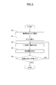
- 6 is a flowchart illustrating a procedure for executing secondary transfer voltage control in the image forming apparatus according to the first embodiment.
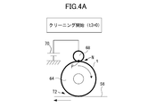
- FIG. 6 is a schematic diagram illustrating a state in which a secondary transfer outer roller and a power supply roller are contaminated with toner in a procedure for executing a cleaning mode of a secondary transfer unit in the image forming apparatus according to the first embodiment.
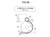
- FIG. 6 is a schematic diagram illustrating a state in which a secondary transfer outer roller makes a half turn in a procedure when executing a cleaning mode of a secondary transfer unit in the image forming apparatus according to the first embodiment.
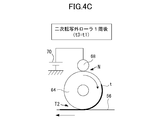
- FIG. 5 is a schematic diagram illustrating a state where a secondary transfer outer roller makes a full turn in a procedure when executing a cleaning mode of a secondary transfer unit in the image forming apparatus according to the first embodiment.
- FIG. 5 is a schematic diagram illustrating a state in which a power feeding roller makes a full turn after a secondary transfer outer roller makes a full turn in a procedure when executing a secondary transfer unit cleaning mode in the image forming apparatus according to the first embodiment. .
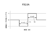
- FIG. 6 is a graph showing a change with time of a cleaning bias applied to the power supply roller according to the first embodiment, and is a total time of a time of one rotation of the secondary transfer outer roller and a time of one rotation of the power supply roller; And a positive cleaning bias is applied once each.
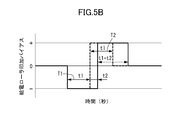
- FIG. 6 is a graph showing a time change of a cleaning bias applied to the power supply roller according to the first embodiment, and a negative polarity and a positive polarity cleaning bias are applied once each time for one round of the secondary transfer outer roller. Is the case. 6 is a flowchart illustrating a processing procedure in a cleaning mode of a secondary transfer unit in the image forming apparatus according to the first embodiment.
- 6 is a graph showing a change with time of a cleaning bias applied to the power supply roller according to the first embodiment, and is a total time of a time of one rotation of the secondary transfer outer roller and a time of one rotation of the power supply roller; This is a case where a positive cleaning bias is applied for a time corresponding to one round of the secondary transfer outer roller.
- 6 is a graph showing a change over time of a cleaning bias applied to the power supply roller according to the first embodiment, in which the negative time is calculated for each of the total time of one turn of the secondary transfer outer roller and one turn of the power supply roller.
- FIG. 6 is a graph showing a change with time of a cleaning bias applied to the power supply roller according to the first embodiment, and is a total time of a time of one rotation of the secondary transfer outer roller and a time of one rotation of the power supply roller;
- the cleaning bias is applied, and the time for one round of the secondary transfer outer roller, the positive cleaning bias, the negative cleaning bias, and the positive cleaning bias are sequentially applied.
- the image forming apparatus 1 is a so-called tandem intermediate transfer type full-color printer in which a plurality of image forming units 10 a, 10 b, 10 c, and 10 d are arranged along the rotation direction (movement direction) of the intermediate transfer belt 56. It is.
- Such an image forming apparatus 1 generates a full-color image on a sheet S which is an example of a recording material by an electrophotographic method in accordance with an image signal transmitted from an external device such as a personal computer or an image signal from an original reading device.
- the sheet S forms a toner image, and specific examples include plain paper, a synthetic resin sheet that is a substitute for plain paper, cardboard, and an overhead projector sheet.
- the image forming apparatus 1 has an apparatus main body (not shown) that accommodates the image forming units 10a, 10b, 10c, and 10d.
- Each of the image forming units 10a to 10d includes photosensitive drums 50a, 50b, 50c, and 50d that rotate in the direction of the arrow in FIG.
- the surfaces of the photosensitive drums 50a to 50d are charged by charging rollers 51a, 51b, 51c, and 51d, respectively.
- Electrostatic latent images are formed on the charged photosensitive drums 50a to 50d by the exposure devices 52a, 52b, 52c, and 52d.
- the electrostatic latent images on the photosensitive drums 50a to 50d are visualized as toner images by the developing devices 53a, 53b, 53c, and 53d in which the respective color component toners are stored.
- each of the developing devices 53a to 53d uses a two-component developer including a non-magnetic toner and a magnetic carrier, and the toner has a negative polarity.
- the developing devices 53a to 53d may be configured to use a one-component developer.
- Primary transfer rollers 54a, 54b, 54c, and 54d are disposed at positions facing the photosensitive drums 50a to 50d with the intermediate transfer belt 56 interposed therebetween, and constitute primary transfer portions T1a, T1b, T1c, and T1d, respectively.
- the toner images of the respective colors formed on the photosensitive drums 50a to 50d are primary-transferred onto the intermediate transfer belt 56 in order by being sequentially superposed by applying a primary transfer bias to the primary transfer rollers 54a to 54d.
- the toner remaining on the photosensitive drums 50a to 50d after the primary transfer is removed by the drum cleaning devices 55a, 55b, 55c, and 55d.
- These image forming units 10a, 10b, 10c, and 10d are arranged in the order of yellow (Y), magenta (M), cyan (C), and black (K) from the upstream side of the intermediate transfer belt 56.
- the sheet S accommodated in a recording material accommodation cassette (not shown) is conveyed from the registration roller 66 to the secondary transfer portion (transfer portion) T2 in synchronization with the toner image formation timing. Then, by applying a secondary transfer bias to the secondary transfer portion T2, the toner image that is primarily transferred and superimposed on the intermediate transfer belt 56 is collectively transferred (secondary transfer) at the secondary transfer portion T2. .
- the detailed configuration of the secondary transfer portion T2 will be described later. Toner and paper powder that are not completely transferred by the secondary transfer portion T2 and remain on the intermediate transfer belt 56 are removed by the belt cleaning device 65.
- the belt cleaning device 65 tensions the intermediate transfer belt 56 across the intermediate transfer belt 56 at a position downstream of the secondary transfer portion T2 and upstream of all the primary transfer portions T1a to T1d with respect to the rotation direction of the intermediate transfer belt 56. It is arranged so as to face the roller 63. Then, the belt cleaning device 65 cleans the surface of the intermediate transfer belt 56 by bringing the blade into contact with the intermediate transfer belt 56 at this position.
- the sheet S is conveyed to a fixing device (not shown). Then, the toner on the sheet S is melted and mixed by being heated and pressurized by the fixing device, and is fixed on the sheet S as a full-color image. Thereafter, the sheet S is discharged to the outside of the apparatus main body. This completes a series of image forming processes. The operation of each device is controlled by the control unit 80.
- the intermediate transfer belt 56 as an image carrier is an endless belt in the form of a film, and carries the toner images primarily transferred from the photosensitive drums 50a to 50d as described above and carried by rotating (moving).
- Such an intermediate transfer belt 56 is made of a resin such as polyimide or polyamide or its alloy, or various rubbers containing an appropriate amount of an antistatic agent such as carbon black.
- the surface resistivity is 1 ⁇ 10 9 to 5 ⁇ 10 13 ⁇ / ⁇ , and the thickness is, for example, about 0.04 to 0.50 mm.
- the intermediate transfer belt 56 is stretched by idler rollers 60, 61, 67, a tension roller 63, and a secondary transfer inner roller 62.
- the tension roller 63 applies a tension of, for example, about 3 to 12 kgf (about 29 to 118 N) to the intermediate transfer belt 56.
- the secondary transfer inner roller 62 is rotationally driven by a drive motor (drive means) 88 to rotate the intermediate transfer belt 56 at a predetermined speed.
- the primary transfer rollers 54a to 54d are provided on the inner side of the intermediate transfer belt 56, and are formed of a metal roller such as SUM (sulfur and sulfur composite free cutting steel) or SUS (stainless steel).
- a voltage (primary transfer bias) having a polarity opposite to the charging polarity of the toner is applied to the primary transfer rollers 54a to 54d.
- a primary transfer contrast which is a potential difference between the surface potential of the photosensitive drums 50a to 50d and the potential of the primary transfer rollers 54a to 54d is formed.
- the toner images on the photosensitive drums 50a to 50d are sequentially electrostatically attracted to the intermediate transfer belt 56 and superimposed on the intermediate transfer belt 56.
- the toner image thus formed is formed.
- the primary transfer rollers 54a to 54d are straight in the thrust direction, and the roller diameter is about 6 to 10 mm.
- the secondary transfer portion T ⁇ b> 2 is formed by a secondary transfer outer roller 64 as a transfer roller coming into contact with the toner image carrying surface (outer surface) of the intermediate transfer belt 56. That is, the secondary transfer outer roller 64 forms a secondary transfer portion T ⁇ b> 2 that transfers the toner image carried on the intermediate transfer belt 56 to the sheet S together with the intermediate transfer belt 56.
- the secondary transfer inner roller 62 is disposed so as to sandwich the intermediate transfer belt 56 with the secondary transfer outer roller 64, and the recording material is sandwiched between the intermediate transfer belt 56 and the secondary transfer outer roller 64. A nip portion is formed. Then, the toner image carried on the intermediate transfer belt 56 is transferred onto the sheet S with respect to the recording material passing through the nip portion.
- the secondary transfer outer roller 64 transfers a toner image from the intermediate transfer belt 56 to the recording material when current is supplied from a power supply roller 68 as a power supply rotating body. That is, the power supply roller 68 rotates in contact with the secondary transfer outer roller 64 at a position different from the secondary transfer portion T2 in the circumferential direction of the power supply roller 68 so that the toner image is transferred by the secondary transfer portion T2.
- a current can be supplied to the secondary transfer outer roller 64.
- a high voltage power supply (power supply) 70 is connected to the power supply roller 68, and a voltage (transfer bias) can be applied to the power supply roller 68.
- the high-voltage power supply 70 supplies an electric field used for secondary transfer and various controls to the secondary transfer unit T2.
- a constant voltage power source is used as the high voltage power source 70.
- the secondary transfer inner roller 62 is configured by providing EPDM (ethylene / propylene / diene rubber) around the cored bar.
- EPDM ethylene / propylene / diene rubber
- the secondary transfer inner roller 62 is formed to have a roller diameter of 20 mm and a rubber thickness of 0.5 mm, and the hardness is set to, for example, 70 ° (Asker C).
- the secondary transfer outer roller 64 has a cored bar 64a as a shaft part having conductivity and an elastic layer 64b as an outer peripheral part including a conductive agent formed on the outer periphery of the cored bar 64a. That is, the secondary transfer outer roller 64 is configured by providing an elastic layer 64b made of NBR (nitrile rubber) or EPDM containing a conductive agent such as a metal complex or carbon around the cored bar 64a. The secondary transfer outer roller 64 is formed so that the roller diameter is 24 mm and the thickness of the elastic layer (sponge layer) 64 b is 6 mm.
- NBR nonrile rubber
- EPDM containing a conductive agent such as a metal complex or carbon
- the power supply roller 68 is positioned so as to contact the secondary transfer inner roller 62 at a power supply nip N (see FIG. 4A) on the opposite side of the secondary transfer outer roller 64.
- a power supply nip N see FIG. 4A
- the power supply roller 68 is arranged so as to be shifted by approximately 180 ° in the rotational direction of 64. Note that the position of the power supply nip N may be another position as long as the position is different from the contact position between the secondary transfer outer roller 64 and the intermediate transfer belt 56.
- the feeding roller 68 is in contact with the secondary transfer outer roller 64 by pressing both ends in the rotation axis direction against the secondary transfer outer roller 64 side with a spring (not shown).
- the power supply roller 68 has a configuration in which a metal roller made of SUM or SUS is coated with a conductive resin containing a conductive substance.
- the diameter of the metal roller is about 4 to 15 mm, and the thickness of the conductive resin is 1 to 200 ⁇ m. If the diameter of the metal roller is smaller than this, deflection occurs when the pressure is applied, and resistance cannot be generated in the secondary transfer outer roller 64 without applying a voltage uniformly in the longitudinal direction (rotation axis direction). There is a possibility that the conductive resin may be cracked or peeled off. On the other hand, if the diameter of the metal roller is larger than this, the material cost increases, and the power supply roller 68 is increased in size and weight. For this reason, it is preferable that the diameter of the metal roller be in the above range.
- Examples of the conductive substance contained in the conductive resin include carbon black and carbon fiber.
- a method for forming the conductive resin first, the above-described conductive substance is dissolved and dispersed in an appropriate organic solvent to obtain a surface layer coating solution. Next, this surface layer coating solution is applied on the outer periphery of the metal roller by a method such as ring coating, dip coating, or spray coating, and dried for the purpose of removing the organic solvent. This drying treatment is desirably performed in an environment of about 30 to 60 ° C. so as not to induce radical reaction. Thereafter, the power supply roller 68 is obtained by curing with an ultraviolet ray using an ultraviolet irradiator.
- a SUS metal roller having a diameter of 8 mm is coated with a 10 ⁇ m conductive resin by dip coating.
- the conductive resin an acrylic resin to which perfluoropolyether and zinc antimonate were added was used.
- the spring pressure of the power supply roller 68 is set to a total pressure of 500 gf (about 4.9 N). This prevents the power supply roller 68 from being bent, and suppresses an increase in component costs and an increase in the size of the secondary transfer portion T2.
- the present invention is not limited to this, and a metal roller such as SUM or SUS may be used as it is, or the surface may be plated. It may be.
- the secondary transfer outer roller 64 rotates following the traveling of the intermediate transfer belt 56. Further, the power supply roller 68 is driven by the rotational drive of the secondary transfer outer roller 64. After various controls are performed, when the sheet S is sent from the registration roller 66 to the secondary transfer portion T2, a power supply roller is used to secondary-transfer the toner image formed on the intermediate transfer belt 56 onto the sheet S.
- a secondary transfer bias having a polarity opposite to the charging polarity of the toner is applied to 68.
- the toner has a negative charging polarity, and a positive polarity bias is applied as the secondary transfer bias.
- an environment detection sensor 85 and a concentration detection sensor 86 for detecting an environment such as temperature and humidity in the device body are provided inside the device body.
- the density detection sensor 86 is disposed opposite to the surface of the intermediate transfer belt 56 on the downstream side of all the primary transfer portions T1a to T1d and on the upstream side of the secondary transfer portion T2, and the toner image on the intermediate transfer belt 56 is disposed. Can be detected.
- the control unit 80 is configured by a computer.
- the CPU 81 the CPU 81, a ROM 82 for storing a program for controlling each unit, a RAM 83 for temporarily storing data, and an input / output for inputting / outputting signals to / from the outside.
- the CPU 81 is a microprocessor that controls the entire control of the image forming apparatus 1 and is the main body of the system controller.
- the CPU 81 is connected to each part of the image forming apparatus 1 via the input / output circuit 84, exchanges signals with each part and controls the operation.
- the ROM 82 stores an image formation control sequence for forming an image on the sheet S, a high voltage output table that indicates the relationship between the temperature and humidity, and the voltage applied to the power supply roller 68.
- the CPU 81 controls the high voltage power source 70 with reference to the high voltage output table, and applies a secondary transfer bias and a cleaning bias described later to the power supply roller 68.
- the control unit 80 is connected to a DA converter 71, an AD converter 73, an environment detection sensor 85, a concentration detection sensor 86, an optical sensor 87, a drive motor 88, and the like.
- the DA converter 71 is connected to the high-voltage power supply 70, converts a digital signal command from the control unit 80 into analog, and outputs a high voltage from the high-voltage power supply 70.
- the high voltage power supply 70 is connected to the current detection unit 72, and the current detection unit 72 detects the current at the time of high voltage output.
- the current detection unit 72 is connected to the AD converter 73, and the detection result of the current detection unit 72 is digitally converted and input to the control unit 80.
- the control unit 80 discharges the toner of the developing devices 53a to 53d onto the intermediate transfer belt 56, and performs belt cleaning. Control to collect by the device 65 is executed.
- the controller 80 applies a reverse polarity bias opposite to the secondary transfer bias to the power supply roller 68 from the high voltage power source 70 during non-image formation.
- the control unit 80 causes the secondary transfer outer roller 64 to contact the intermediate transfer belt 56 while the secondary transfer outer roller 64 and the power supply roller 68 are in contact with each other while applying a reverse polarity bias.
- the secondary transfer outer roller 64, the power supply roller 68, and the intermediate transfer belt 56 are rotated.
- the control unit 80 transfers the toner attached to the power supply roller 68 to the intermediate transfer belt 56 via the secondary transfer outer roller 64 to clean the power supply roller 68 (hereinafter also referred to as cleaning control). Can be executed.
- the control unit 80 applies a reverse polarity bias to the power supply roller 68 (t1 + t2) as cleaning control.
- a first cleaning mode having a period of continuous application is provided.
- the control unit 80 executes the first cleaning mode before resuming image formation.
- the control unit 80 performs the cleaning control after the control toner image passes through the secondary transfer unit T2. 1 cleaning mode is executed.
- the first cleaning mode when there are a plurality of first application periods T1, the first period is set to be the longest among the plurality of periods.
- the cleaning mode includes a second cleaning mode in which the reverse polarity bias is continuously applied to the power supply roller 68 and is less than (t1 + t2) at the longest.
- the control unit 80 executes the second cleaning mode when starting or ending the image forming operation.
- the control unit 80 when the time during which the reverse polarity bias is continuously applied is t3, the control unit 80 is a mode in which the second cleaning mode does not exceed t1 + t2 at most, and t1 ⁇ In this mode, the relationship of t3 ⁇ t1 + t2 is satisfied (step S13 in FIG. 6).
- the first cleaning mode is a mode having at least a period satisfying the relationship of t3 ⁇ t1 + t2 (step S14 in FIG. 6).
- the control unit 80 may switch the cleaning mode according to the image ratio when the cleaning control is executed before the image formation is restarted after the sheet S is jammed. That is, the first cleaning mode may be executed if the image ratio of the image carried on the intermediate transfer belt 56 when a jam occurs is equal to or greater than a predetermined ratio. On the other hand, the control unit 80 may execute the first cleaning mode or the second cleaning mode if the image ratio of the image held on the intermediate transfer belt 56 is less than the predetermined ratio when the jam occurs. Good. In addition, the control unit 80 may execute the second cleaning mode when executing the cleaning control when the image forming operation starts or ends.
- the first cleaning mode has a period in which the high-voltage power supply 70 continuously applies the same polarity bias as the transfer bias to the power supply roller 68 for (t1 + t2) or more.
- the second cleaning mode has a period in which the same polarity bias having the same polarity as the transfer bias is continuously applied from the high voltage power source 70 to the power supply roller 68, and the period in which the same polarity bias is applied is long (t1 + t2). Is less than.
- the controller 80 rotates the intermediate transfer belt 56, the secondary transfer outer roller 64, and the power supply roller 68 while applying a reverse polarity bias from the high voltage power source 70 in the cleaning control. Thereafter, the controller 80 rotates the intermediate transfer belt 56, the secondary transfer outer roller 64, and the power supply roller 68 while applying the same polarity bias as the transfer bias from the high voltage power source 70, thereby removing the secondary transfer outside.
- the roller 64 and the power supply roller 68 can be cleaned.
- the control unit 80 can execute the second cleaning mode during a normal operation and can execute the first cleaning mode during a predetermined operation.
- the predetermined operation time is, for example, an operation time when the toner contamination amount is a predetermined amount or more
- a normal operation time is an operation time when the toner contamination amount is less than the predetermined amount.
- an image forming job is a series of operations performed as follows based on a print command signal (image forming command signal).
- a print command signal image forming command signal
- the pre-operation necessary for ending the image formation is completed through the image forming process.
- It is a series of operations up to. Specifically, it refers to the period from pre-rotation (preparation operation before image formation) after receiving a print command signal (input of image formation job) to post-rotation (operation after image formation). It includes the period and the interval between sheets (during non-image formation). In addition, the interval between sheets corresponds to a gap between a toner image formed on one sheet and a toner image formed on the next sheet when image formation is continuously performed. It is a period to do.
- the image forming operation is started, first, the photosensitive drums 50a to 50d are rotated and the surfaces are charged by the charging rollers 51a to 51d. Then, laser light is emitted to the photosensitive drums 50a to 50d based on the image information by the exposure devices 52a to 52d, and electrostatic latent images are formed on the surfaces of the photosensitive drums 50a to 50d.
- the electrostatic latent image is developed by developing devices 53 a to 53 d to be visualized as a toner image and transferred to the intermediate transfer belt 56.
- the sheet S is supplied in parallel with the toner image forming operation, and the sheet S is conveyed to the secondary transfer portion T2 via the conveyance path in synchronization with the toner image on the intermediate transfer belt 56. . Further, the image is transferred from the intermediate transfer belt 56 to the sheet S, and the sheet S is conveyed to a fixing device, where an unfixed toner image is heated and pressed to be fixed on the surface of the sheet S and discharged from the apparatus main body. Is done.
- the control unit 80 sets the secondary transfer voltage (ATVC) during the pre-rotation so that a desired secondary transfer current value (in this embodiment, for example, ⁇ 40 ⁇ A) flows. (Step S2). Specifically, the control unit 80 calculates a VI characteristic from each detected current value when two or more different arbitrary voltage values are applied, and determines a voltage value to be applied in order to obtain a target current value. obtain. Further, the control unit 80 adds a shared voltage corresponding to a sheet type such as plain paper or cardboard previously stored in the ROM 82 to the voltage value calculated above so that a desired transfer current flows. The voltage applied to 68 is set as the secondary transfer voltage.
- ATVC secondary transfer voltage
- the control unit 80 applies the secondary transfer voltage calculated by ATVC from the power supply roller 68 to the secondary transfer unit T2, and performs image formation (step S3). In the interval between sheets after image formation, the control unit 80 applies an inter-sheet voltage from the power supply roller 68 to the secondary transfer unit T2 (step S4). Further, the control unit 80 determines whether or not the image forming job is finished (step S5). If the control unit 80 determines that the image forming job has not ended, the secondary transfer voltage is applied again from the power supply roller 68 to the secondary transfer unit T2 to perform image formation (step S3). When the control unit 80 determines that the image forming job is finished, the secondary transfer voltage control is finished.
- cleaning control for applying a cleaning bias to the power supply roller 68 can be executed at a timing when the toner image is not transferred to the sheet S by the secondary transfer portion T2.
- the timing for executing such cleaning control is after execution of jam processing, after execution of a control mode such as adjustment of toner density or toner image positional deviation.
- the jam processing is processing that removes the sheet S when a jam occurs, for example, in the conveyance path of the image forming apparatus 1 during the image forming operation. In this case, a jam may occur when the toner image is placed on the intermediate transfer belt 56, and a large amount of toner on the intermediate transfer belt 56 may adhere to the secondary transfer outer roller 64 after the jam processing. There is.
- patch images as control toner images are formed by the image forming units 10a to 10d, carried on the intermediate transfer belt 56, and detected by the density detection sensor 86. Based on the result detected by the density detection sensor 86, the density adjustment of the toner image and the correction of the positional deviation of the toner image of each of the image forming units 10a to 10d are performed. Since the patch image is not transferred to the sheet S at the secondary transfer portion T2, a large amount of toner on the intermediate transfer belt 56 may adhere to the secondary transfer outer roller 64 after execution of such a control mode.
- the outline of the cleaning control of the secondary transfer portion T2 will be described with reference to FIGS. 4A to 4D.
- fog toner on the intermediate transfer belt 56 after the sheet S passes is attached to the secondary transfer outer roller 64 and the power supply roller 68.
- the amount of toner contamination in the next transfer portion T2 is small.
- a reverse polarity bias of the same polarity as that of the toner that is, a reverse polarity of the secondary transfer bias is applied to the feeding nip portion N between the secondary transfer outer roller 64 and the feeding roller 68 for one turn of the secondary transfer outer roller 64.
- Apply for time t1 As a result, all of the toner adhering to the secondary transfer outer roller 64 can be discharged to the intermediate transfer belt 56, and the secondary transfer outer roller 64 can be sufficiently cleaned.
- the secondary transfer is performed without the sheet S immediately after the control mode for detecting the patch density on the intermediate transfer belt 56 by the density detection sensor 86 and correcting the density, or when a paper jam occurs.
- a large amount of toner may pass through the portion T2.
- a large amount of toner may be attached at the secondary transfer portion T2. This is because toner passes through the secondary transfer portion T2 in the absence of the sheet S, so that toner adheres to the secondary transfer outer roller 64 easily.
- FIGS. 4A to 4D A case where a large amount of toner adheres to the secondary transfer portion T2 will be described with reference to FIGS. 4A to 4D.
- the controller 80 causes the power supply roller 68 to have the same polarity as the toner, that is, opposite to the secondary transfer bias.
- a reverse polarity bias of polarity is applied as a cleaning bias.
- the secondary transfer outer roller 64 is cleaned by a half turn after the half turn of the secondary transfer outer roller 64, and the toner stain t remains in the half turn.
- the toner stain t remains on the entire circumference. This is because, during the operation in which the secondary transfer outer roller 64 makes a half-turn, the toner is always applied to both the secondary transfer outer roller 64 and the power supply roller 68 at the power supply nip N between the secondary transfer outer roller 64 and the power supply roller 68. This is because the dirt t remains and the power supply roller 68 is not cleaned.
- the cleaning bias from the power supply roller 68 is insufficient, and the toner stain t on the power supply roller 68 may not be sufficiently cleaned.
- the toner on the secondary transfer outer roller 64 may adhere to the power supply roller 68 with a non-electrostatic adhesion force. For this reason, the cleaning of the power supply roller 68 is substantially started after a half turn of the secondary transfer outer roller 64 as shown in FIG. 4B.
- the already cleaned portion of the secondary transfer outer roller 64 reaches the power feeding nip portion N. Therefore, the toner stain t remaining on the power supply roller 68 is transferred onto the secondary transfer outer roller 64 and the power supply roller 68 is cleaned. That is, as shown in FIG. 4C, when cleaning for one round of the secondary transfer outer roller 64 is performed, toner dirt t for one round of the power supply roller 68 remains on the secondary transfer outer roller 64. It becomes a state.
- the secondary transfer outer roller 64 and the power supply roller 68 are cleaned by performing cleaning for a time t2 corresponding to one rotation of the power supply roller 68 after one turn of the secondary transfer outer roller 64. Both cleanings can be finished.
- a time corresponding to one round of the secondary transfer outer roller 64 is obtained.
- time t2 for one rotation of the power supply roller 68 is required.
- the cleaning bias applied to the power supply roller 68 in the cleaning control of the secondary transfer portion T2 will be described with reference to FIG. 5A.
- the dirt on the secondary transfer outer roller 64 and the power supply roller 68 is cleaned by the cleaning bias applied in the cleaning control.
- the toner adhering to the secondary transfer outer roller 64 is a mixture of electrically positively charged toner and negatively charged toner.
- the toner is transferred to the intermediate transfer belt 56 using this electrical characteristic. Pull back up.
- the positively charged toner can be cleaned by applying the same polarity bias as the secondary transfer bias in the direction from the power supply roller 68 to the secondary transfer inner roller 62 as the cleaning bias.
- the negatively charged toner can be cleaned by applying a reverse polarity bias opposite to the secondary transfer bias in the direction from the secondary transfer inner roller 62 to the power supply roller 68 as a cleaning bias.
- the secondary transfer outer roller 64 By electrically floating the secondary transfer outer roller 64, a bias can be applied in both directions between the power supply roller 68 and the secondary transfer inner roller 62 with the secondary transfer outer roller 64 interposed therebetween. . For this reason, the secondary transfer outer roller 64 and the power supply roller 68 can be cleaned by one high-voltage power supply 70.
- a positive polarity positive polarity bias is applied as a cleaning bias.
- the positively charged toner adhering to the secondary transfer outer roller 64 and the power supply roller 68 can be removed.
- the time for one turn of the power supply roller 68 is longer than the time t1 for one turn of the secondary transfer outer roller 64. It is preferable to apply a bias voltage longer by t2.
- the cleaning bias is always applied during t1 + t2, for example, if the amount of contaminated toner between the secondary transfer outer roller 64 and the power supply roller 68 is small, excessive cleaning processing is performed, and image formation is produced. Efficiency may be reduced.
- the processing time in the cleaning control is switched according to the toner adhesion amount of the secondary transfer portion T2, thereby reducing the processing time and reducing the power supply roller 68 and the secondary transfer outside. The roller 64 can be cleaned well.
- the control unit 80 determines whether it is time to execute the cleaning control (cleaning mode) (step S10).
- the timing for executing the cleaning control is, for example, when the image forming apparatus 1 is turned on, when an image forming job is performed by the user, when returning from a paper jam, or when discharged toner is discharged. is there. That is, when the image forming apparatus 1 returns from the stopped state, a large amount of toner is supplied to the secondary transfer unit without the sheet S, or the like. However, it is needless to say that it is not limited to these times.
- control unit 80 determines that it is not time to execute the cleaning control, the process ends.
- the control unit 80 detects the operation history of the image forming apparatus 1 and predicts the toner contamination amount of the secondary transfer outer roller 64 or the power supply roller 68. (Step S11).
- the CPU 81 reads the operation history of the image forming apparatus 1 stored in the ROM 82 or the RAM 83 and predicts the toner contamination amount.
- the operation history is information related to the toner contamination amount of the secondary transfer outer roller 64 or the power supply roller 68.
- the application time of the cleaning bias in the previous cleaning control, the image ratio and the number of printed sheets in the subsequent image forming process, the presence or absence of a paper jam, the presence or absence of toner discharge, whether a patch image is formed, or an intermediate transfer belt when a jam occurs Information such as the image ratio of the image carried by the camera 56 is used. For this reason, since it is not necessary to provide a dedicated member for predicting the toner contamination amount, an increase in the number of parts can be suppressed.
- the toner contamination amount of the secondary transfer outer roller 64 or the power supply roller 68 is predicted to be small, for example, at the time of post-rotation after normal image formation.
- the toner contamination amount of the secondary transfer outer roller 64 or the power supply roller 68 is predicted to be large.
- the control unit 80 when it is determined that the state of the toner stored in the developing devices 53a to 53d has deteriorated due to durability or environmental fluctuation, the control unit 80 performs intermediate transfer of the toner of the developing devices 53a to 53d.
- the ink is discharged onto the belt 56 and collected by the belt cleaning device 65.
- a large amount of toner passes through the secondary transfer portion T ⁇ b> 2 without the sheet S, a large amount of toner adheres to the secondary transfer outer roller 64 and the power supply roller 68. For this reason, the toner contamination amount of the secondary transfer outer roller 64 or the power supply roller 68 is predicted to be large.
- the control unit 80 applies a positive polarity same polarity bias as a cleaning bias for a time t1 of one round of the secondary transfer outer roller 64 (see the broken line in FIG. 5B). ).
- the toner of the secondary transfer outer roller 64 and the power supply roller 68 can be discharged to the intermediate transfer belt 56, and the execution of the cleaning control is finished.
- the processing time can be reduced by setting the time t1 for one rotation of the secondary transfer outer roller 64 as positive and negative as the cleaning bias application time t3. .
- the control unit 80 determines that the predicted toner contamination amount is equal to or greater than the predetermined amount, the toner contamination amount is large, and thus cleaning control is executed as during a predetermined operation.
- the large amount of toner exists in the secondary transfer outer roller 64 only during the time t1 when the secondary transfer outer roller 64 makes one round, it is difficult to discharge the toner from the power supply roller 68.
- a negative polarity reverse polarity bias is applied as a cleaning bias for a time t1 corresponding to one turn of the secondary transfer outer roller 64, and then continuously for one turn of the power supply roller 68.
- the time t2 is applied. That is, the reverse polarity bias is applied at least for the period of t1 + t2.
- the toner of the secondary transfer outer roller 64 and the power supply roller 68 can be discharged to the intermediate transfer belt 56, and the execution of the cleaning control is finished.
- sufficient cleaning of the secondary transfer outer roller 64 and the power supply roller 68 can be realized by setting t1 + t2 as the cleaning bias application time t3 for both positive and negative. .
- the control unit 80 determines that the image ratio of the image formed immediately before is less than a predetermined ratio (step S12; NO), the second cleaning mode is executed (step S13). Further, for example, when the sheet S is jammed (step S10; YES), the control unit 80 determines that the first image forming ratio is equal to or greater than a predetermined ratio (step S12; YES).
- the cleaning mode is executed (step S14).
- a jam for example, a case has been described in which the first cleaning mode and the second cleaning mode are switched according to the image ratio, but the present invention is not limited thereto. For example, when a jam occurs, the first cleaning mode may always be executed regardless of the image ratio.
- the control unit 80 has the first cleaning mode in which the reverse polarity bias is continuously applied to the power supply roller 68 for (t1 + t2) or more as the cleaning control. It has. Therefore, the toner attached to the secondary transfer outer roller 64 and the power supply roller 68 can be electrostatically transferred to the intermediate transfer belt 56 for cleaning. Thereby, in the image forming apparatus 1 having the power supply roller 68, it is possible to suppress the reattachment of toner to the sheet S without separately providing a cleaning member for the power supply roller 68.
- the controller 80 applies the reverse polarity bias opposite to the transfer bias from the high-voltage power supply 70 in the cleaning control while the intermediate transfer belt 56 and the secondary transfer outer roller. 64 and the feeding roller 68 can be rotated. Thereafter, the controller 80 rotates the intermediate transfer belt 56, the secondary transfer outer roller 64, and the power supply roller 68 while applying the same polarity bias as the transfer bias from the high voltage power source 70, thereby removing the secondary transfer outside.
- the roller 64 and the power supply roller 68 can be cleaned.
- negatively charged toner can be cleaned by applying a reverse polarity bias
- positively charged toner can be cleaned by applying the same polarity bias. For this reason, both negatively charged toner and positively charged toner can be cleaned by a series of operations, and efficient cleaning can be realized.
- the control unit 80 determines that the predicted toner contamination amount is less than the predetermined amount
- the control unit 80 executes the second cleaning mode on the assumption that the normal operation is being performed. To do.
- the control unit 80 executes the first cleaning mode assuming that the predetermined operation is being performed. For this reason, since the cleaning mode is switched according to the amount of toner contamination, the electrostatic cleaning characteristics of the secondary transfer outer roller 64 and the power supply roller 68 to which the toner adheres can be maintained while maintaining the productivity. A decrease can be avoided.
- the cleaning bias application time t3 is made equal to the sum of the time t1 for one rotation of the secondary transfer outer roller 64 and the time t2 for one rotation of the power supply roller 68.
- the application time t3 of the cleaning bias is not shortened more than necessary, and the secondary transfer outer roller 64 and the power supply roller 68 to which the toner has adhered can be cleaned satisfactorily.
- control unit 80 predicts the toner contamination amount based on the operation history of the image forming apparatus 1, and thus a dedicated member for predicting the toner contamination amount. No increase in the number of parts can be suppressed.
- the control unit 80 executes the second cleaning mode if the image ratio of the image formed immediately before is less than the predetermined ratio. If the image ratio is equal to or greater than the predetermined ratio, the first cleaning mode is executed. For this reason, even when the sheet S is jammed, it is possible to avoid a decrease in productivity while maintaining good electrostatic cleaning characteristics of the secondary transfer outer roller 64 and the power supply roller 68 to which the toner has adhered. it can.
- the cleaning bias application time t3 may satisfy the relationship of t1 ⁇ t3 ⁇ t1 + t2. In this case as well, the cleaning bias application time t3 is not increased more than necessary, and a reduction in productivity can be avoided.
- the cleaning bias application time t3 may satisfy the relationship of t3 ⁇ t1 + t2.
- the application time t3 of the cleaning bias is not shortened more than necessary, and the secondary transfer outer roller 64 and the power supply roller 68 to which the toner adheres can be cleaned well. In the first cleaning mode, it is only necessary to satisfy the relationship of t3 ⁇ t1 + t2.
- a period of applying the cleaning bias is (t1 + t2) ⁇ 10 ⁇ t3 ⁇ t1 + t2. Is preferable. Furthermore, the period during which the cleaning bias is applied is more preferably (t1 + t2) ⁇ 5 ⁇ t3 ⁇ t1 + t2. Thereby, it is possible to avoid a decrease in productivity while maintaining good electrostatic cleaning characteristics of the secondary transfer outer roller 64 and the power supply roller 68.
- the application time of the same polarity bias may be different from the application time of the reverse polarity bias.
- the application time of the same polarity bias may be t1 + t2.
- the application time of the same polarity bias may be t1.
- the time for applying the same-polarity bias may be a time for at least one round of the secondary transfer outer roller 64.
- the relationship of t1 ⁇ t4 ⁇ t1 + t2 may be satisfied.
- the reverse polarity bias and the same polarity bias are sequentially applied once in each cleaning mode.
- the present invention is not limited to this.
- the reverse polarity bias and the same polarity bias may be sequentially applied, and then the reverse polarity bias and the same polarity bias may be sequentially applied in succession.
- the first reverse-polarity bias application time is t1 + t2
- the first positive-polarity bias application time is t1 + t2
- the second reverse-polarity bias application time is t1 and t2.
- the positive bias application time may be t1.
- the application time of the first reverse polarity bias is t1 + t2, the first positive polarity bias, the second reverse polarity bias, and the second positive polarity bias.
- Each application time may be t1.
- the application time of the positive polarity bias can be shortened because most of the toner adhering to the secondary transfer outer roller 64 and the power supply roller 68 by the first application of the reverse polarity bias is removed. This is because it can be cleaned.
- both the reverse polarity bias and the same polarity bias are applied as the cleaning control.
- the present invention is not limited to this.
- only the reverse polarity bias may be applied and the same polarity bias may not be applied. This is because the positively charged toner has less content in the developer than the negatively charged toner.
- t1 is a rotation time for one rotation of the secondary transfer outer roller 64 and t2 is a rotation time for one rotation of the power supply roller 68.
- t1 ⁇ t2 may be sufficient.
- the time for applying the bias of each polarity (see step S13) may be t2 instead of t1. That is, when t1 ⁇ t2, the time for applying the bias of each polarity in the second cleaning mode is set to t2, so that the secondary transfer outer roller 64 and the bias of each polarity are continuously applied while the bias of each polarity is being applied.
- Each of the power supply rollers 68 can be rotated once.
- the present invention is not limited thereto.
- the application time may be shorter than t1 + t2.
- the position of the intersection of the line connecting the center of the secondary transfer outer roller 64 and the power feeding roller 68 and the secondary transfer outer roller 64 at the start of applying the cleaning bias is the point P (see FIG. 4A).
- the point P is a point in contact with the power supply roller 68 of the secondary transfer outer roller 64 at the start of cleaning.
- the point P reaches the intermediate transfer belt 56, that is, the secondary transfer portion T2 (see FIG. 4B).
- t0 the time for which the secondary transfer outer roller 64 rotates half a round
- one round of toner adhering to the power supply roller 68 is conveyed to the intermediate transfer belt 56 via the secondary transfer outer roller 64.
- the time required for this is (t2 + t0).
- the time required for one round of toner adhering to the secondary transfer outer roller 64 to be carried to the intermediate transfer belt 56 is t1.
- the reverse polarity bias and the continuous application time of the same polarity bias are either t1 or (t2 + t0). Of these, it is sufficient if it is longer than the longer one. That is, if t1 ⁇ (t2 + t0), it is preferable that there is a period in which the reverse polarity bias and the same polarity bias are continuously applied at least t1 or more in the cleaning control.
- the continuous application time of the reverse polarity bias and the same polarity bias may be longer than either t1 or (t2 + t0).
- the continuous application time of the cleaning bias is set to be longer than t1 and (t2 + t0), it is preferable to set an upper limit value for the continuous application time in consideration of productivity.
- the continuous application time of the cleaning bias is preferably tL ⁇ 10 or less, and tL ⁇ 5 or less. Is more preferable. Thereby, it is possible to avoid a decrease in productivity while maintaining good electrostatic cleaning characteristics of the secondary transfer outer roller 64 and the power supply roller 68.
- an optical sensor (detection means) 87 is provided so as to face the surface of the power supply roller 68.
- the optical sensor 87 is connected to the control unit 80 (see FIG. 2) and can detect the reflectance of the surface of the power supply roller 68 as a value related to toner contamination of the power supply roller 68.
- the optical sensor 87 is a sensor that detects the regular reflection component of the reflected light of the light emitted from the light emitting unit toward the surface of the power supply roller 68 at the light receiving unit.
- the optical sensor 87 determines the amount of toner adhesion using the fact that the amount of specular reflection is small when the toner adhesion amount of the power supply roller 68 is large and the amount of specular reflection is large when the amount of toner adhesion is small. Yes.
- the control unit 80 executes the second cleaning mode when the reflectance detected by the optical sensor 87 is less than a predetermined value, and executes the first cleaning mode when the reflectance is greater than or equal to the predetermined value.
- step S21 is provided instead of step S11 in the flowchart shown in FIG. 6 as shown in FIG.
- step S10 the control unit 80 determines whether it is time to execute the cleaning control
- the control unit 80 determines that it is time to execute the cleaning control, the control unit 80 detects the reflectance of the power supply roller 68 from the optical sensor 87, and detects the amount of toner contamination of the power supply roller 68 based on the reflectance (see FIG. Step S21).
- the amount of reflected light of the power supply roller 68 stored in the ROM 82 in the new state in advance is the amount of reflected light when no toner adheres, for example, the amount of reflected light is less than half from the new state. Is detected, the toner adhesion amount is determined to be large.
- the controller 80 executes the second cleaning mode if the toner contamination amount is not greater than or equal to the predetermined value (step S13), and if the toner contamination amount is greater than or equal to the predetermined value, the controller 80 executes the first cleaning mode (step S13). S14).
- the control unit 80 includes a first cleaning mode having a period in which a reverse polarity bias is continuously applied to the power supply roller 68 for (t1 + t2) or more as cleaning control. Therefore, the toner attached to the secondary transfer outer roller 64 and the power supply roller 68 can be electrostatically transferred to the intermediate transfer belt 56 for cleaning. Thereby, in the image forming apparatus 1 having the power supply roller 68, it is possible to suppress the reattachment of toner to the sheet S without separately providing a cleaning member for the power supply roller 68.
- the cleaning bias application time t3 is not increased more than necessary, and a reduction in productivity can be avoided.
- the cleaning bias application time t3 is not shortened more than necessary, and the secondary transfer outer roller 64 and the power supply roller 68 to which the toner is adhered can be cleaned satisfactorily. As a result, it is possible to avoid a decrease in productivity while maintaining good electrostatic cleaning characteristics of the secondary transfer outer roller 64 and the power supply roller 68 to which the toner has adhered.
- the optical sensor 87 is applied as a detection unit that detects a value related to toner contamination of the power supply roller 68, the amount of toner contamination can be directly detected and cleaning is performed. Mode switching can be performed with high accuracy.
- the optical sensor 87 can detect the reflectance of the surface of the power supply roller 68 in the image forming apparatus 1 of the second embodiment described above.
- the present invention is not limited to this.
- the reflectance of the surface of the roller 64 may be detectable. That is, the optical sensor 87 only needs to detect the reflectance of at least one of the secondary transfer outer roller 64 and the power supply roller 68. In any case, the toner contamination amount can be directly detected, and the cleaning mode can be switched with high accuracy.
- the optical sensor 87 is applied as a detection unit that detects a value related to toner contamination of at least one of the secondary transfer outer roller 64 and the power supply roller 68
- the detection unit may be a current detection unit that detects a transfer current of the secondary transfer portion T2.
- the control unit 80 uses the value relating to the relationship between the current detected by the current detection means when the test bias is applied to the power supply roller 68 during non-image formation and the applied test bias as a detection value. The amount of toner contamination of the next transfer outer roller 64 can be detected. According to this, the control unit 80 does not need to provide a dedicated member for detecting the toner contamination amount, and can suppress an increase in the number of parts.
- the detection unit may be a current detection unit that detects a current when the drive motor 88 of the secondary transfer inner roller 62 is driven.
- the control unit 80 can detect the amount of toner contamination of the secondary transfer inner roller 62 using the current when the drive motor 88 detected by the current detection unit is driven as a detection value.
- toner contamination accumulates on the secondary transfer outer roller 64, the rotational resistance of the secondary transfer outer roller 64 in the power feeding nip N increases, so that the drive torque of the intermediate transfer belt 56 increases, and the drive motor 88 The current during driving varies.
- control unit 80 detects the driving torque of the intermediate transfer belt 56 based on the current when the driving motor 88 of the secondary transfer inner roller 62 is driven, and if this driving torque is large, the toner contamination amount is large. to decide. Also in this case, the controller 80 does not need to provide a dedicated member for detecting the toner contamination amount, and can suppress an increase in the number of parts.
- the process speed is set to a peripheral speed of 300 mm / sec, and the toner contamination of the power supply roller 68 is investigated. did.
- a full gradation solid image and a halftone image are formed with black toner without using the sheet S, and the secondary transfer portion T2 is intentionally contaminated with toner by passing through the secondary transfer portion T2, and thereafter
- the effect of the cleaning control to be implemented was confirmed.
- the effect of the cleaning control was confirmed by passing the sheet S through the image forming apparatus 1 after executing the cleaning control and then confirming toner adhesion on the back surface.
- the power source of the apparatus main body is turned on after the image formation is performed until the sheet S passes through the secondary transfer portion T2. After that, the power of the main body was turned on again. Accordingly, the toner can be sent to the secondary transfer portion T2 without passing the sheet S.
- Example 1 As shown in FIG. 5A, with the same polarity bias set to 1 kV and the reverse polarity bias set to ⁇ 1 kV without using a sheet, the secondary transfer outer roller 64 makes one turn and the feed roller 68 makes one turn. Each bias was applied for a total time t1 + t2 with t2. As a result, it was confirmed that the black toner did not adhere to the back surface of the sheet S that passed after cleaning control.
- Example 2 5000 sheets of A4 size paper (manufactured by Canon, GF-C081 (basis weight 81.4 g / m 2 )) was continuously passed.
- the same polarity bias is set to 1 kV
- the reverse polarity bias is set to ⁇ 1 kV
- each bias is applied during the rotation time t1 in which the secondary transfer outer roller 64 makes one round.
- the image forming apparatus 1 of the present embodiment it is possible to avoid a decrease in productivity while maintaining good electrostatic cleaning characteristics of the secondary transfer outer roller 64 and the power supply roller 68 to which toner has adhered. Confirmed that you can.
- the present image forming apparatus can be used for an image forming apparatus such as a copying machine, a printer, a facsimile machine, or a multi-function machine having a plurality of these functions, and is particularly suitable for an apparatus having a feeding rotating body.
Landscapes
- Physics & Mathematics (AREA)
- General Physics & Mathematics (AREA)
- Electrostatic Charge, Transfer And Separation In Electrography (AREA)
Abstract
二次転写部と異なる位置で転写ローラと当接して回転し、二次転写部でトナー像を転写すべく転写ローラに電流を供給可能な給電ローラと、記録材のジャムが発生した場合に画像形成を再開する前に、中間転写ベルトと転写ローラと給電ローラとを回転させながら、給電ローラへ逆極性バイアスを印加することにより、給電ローラに付着したトナーを転写ローラを介して中間転写ベルトへ転移させて給電ローラを清掃する清掃モード(ステップS10)を実行する制御部と、を備え、制御部は、転写ローラの回転時間をt1、給電ローラの回転時間をt2とし、給電ローラへ逆極性バイアスを(t1+t2)以上継続して印加する期間を有する清掃モード(ステップS14)を実行する。
Description
本発明は、複写機、プリンタ、ファクシミリ、これらの複数の機能を有する複合機などの画像形成装置に関する。
従来から、感光ドラムに形成したトナー像を像担持体としての中間転写ベルトに一次転写し、中間転写ベルトからトナー像を記録材に二次転写する中間転写方式の画像形成装置が知られている。トナー像を記録材に二次転写する二次転写部には、中間転写ベルトの外周面と当接する転写ローラ(二次転写外ローラ)が配置され、転写ローラに転写電圧が印加されることによって二次転写が行われる。
転写ローラは、導電性の軸部の周面に弾性層が設けられ、弾性層にはイオン導電剤などの導電剤が分散されて導電性が付与されている。したがって、使用により転写ローラへの電圧の印加時間が多くなると、イオン導電剤内のイオンがローラ表面側又は軸部側の一方に偏るように分極し、電気抵抗が上昇しやすい。そこで、分極に起因する電気抵抗の上昇を抑制するために、転写ローラの表面に当接させた給電回転体としての給電ローラから転写ローラに電圧を印加して、中間転写ベルトから記録材にトナー像を転写させる画像形成装置が提案されている(特許文献1)。
しかしながら、特許文献1に記載された転写ローラでは、トナーが中間転写ベルトから転写ローラへ付着した場合には、転写ローラに当接する給電ローラにも付着することがある。給電ローラにトナー付着が起こると、給電ローラから転写ローラに流れる電流のムラが生じる可能性がある。また、給電ローラに付着したトナーが転写ローラへ再付着し、記録材の裏面を汚してしまう場合がある。
これを解決すべく給電ローラへのトナー付着を抑制するため、給電ローラに清掃部材を設ける構成や、給電ローラにトナーと同極性の電圧を印加することで静電的に給電ローラをクリーニングする構成が考えられる。給電ローラに清掃部材を設ける構成ではトナーの回収部の設置が必要となり、画像形成装置が大型化してしまうため、静電的にクリーニングする構成が望ましい。静電的にクリーニングする構成では、給電ローラから転写ローラにトナーが移転してしまうため、記録材へのトナーの再付着を抑制すべく転写ローラも清掃する必要がある。
そこで、本発明は、給電回転体を有する画像形成装置において、別途、給電回転体に清掃部材を設けることなく、記録材へのトナーの再付着を抑制可能な画像形成装置を提供することを目的とする。
本発明の画像形成装置は、トナー像を担持する像担持体と、導電性を有する軸部と、前記軸部の外周に形成された導電剤を含む外周部とを有し、前記像担持体の外表面に接触して前記像担持体に担持されたトナー像を記録材へ転写する転写部を形成する転写ローラと、前記転写ローラの周方向に関して、前記転写部とは異なる位置で前記転写ローラと当接して回転し、前記転写部でトナー像を転写すべく前記転写ローラに電流を供給可能な給電回転体と、前記給電回転体に転写バイアスを印加可能な電源と、記録材のジャムが発生した場合に、画像形成を再開する前に、前記像担持体と前記転写ローラと前記給電回転体とを回転させながら、前記電源から前記給電回転体へ前記転写バイアスと逆極性の逆極性バイアスを印加することにより、前記給電回転体に付着したトナーを前記転写ローラを介して前記像担持体へ転移させて前記給電回転体を清掃する清掃モードを実行可能な制御部と、を備え、前記制御部は、前記転写ローラが1周する回転時間をt1、前記給電回転体が1周する回転時間をt2としたとき、前記清掃モードにおいて、前記電源から前記給電回転体へ前記逆極性バイアスを(t1+t2)以上継続して印加する期間を有するように前記清掃モードを実行する。
また、本発明の画像形成装置は、トナー像を担持する像担持体と、導電性を有する軸部と、前記軸部の外周に形成された導電剤を含む外周部とを有し、前記像担持体の外表面に接触して前記像担持体に担持されたトナー像を記録材へ転写する転写部を形成する転写ローラと、前記転写ローラの周方向に関して、前記転写部とは異なる位置で前記転写ローラと当接して回転し、前記転写部でトナー像を転写すべく前記転写ローラに電流を供給可能な給電回転体と、前記給電回転体に転写バイアスを印加可能な電源と、非画像形成時に前記像担持体に所定の制御用トナー像を形成した場合、前記所定の制御用トナー像が前記転写部を通過した後に、前記像担持体と前記転写ローラと前記給電回転体とを回転させながら、前記電源から前記給電回転体へ前記転写バイアスと逆極性の逆極性バイアスを印加することにより、前記給電回転体に付着したトナーを前記転写ローラを介して前記像担持体へ転移させて前記給電回転体を清掃する清掃モードを実行可能な制御部と、を備え、前記制御部は、前記転写ローラが1周する回転時間をt1、前記給電回転体が1周する回転時間をt2としたとき、前記清掃モードにおいて、前記電源から前記給電回転体へ前記逆極性バイアスを(t1+t2)以上継続して印加する期間を有するように前記清掃モードを実行する。
また、本発明の画像形成装置は、トナー像を担持する像担持体と、導電性を有する軸部と、前記軸部の外周に形成された導電剤を含む外周部とを有し、前記像担持体の外表面に接触して前記像担持体に担持されたトナー像を記録材へ転写する転写部を形成する転写ローラと、前記転写ローラの周方向に関して、前記転写部とは異なる位置で前記転写ローラと当接して回転し、前記転写部でトナー像を転写すべく前記転写ローラに電流を供給可能な給電回転体と、前記給電回転体に転写バイアスを印加可能な電源と、非画像形成時において、前記像担持体と前記転写ローラと前記給電回転体とを回転させながら、前記電源から前記給電回転体へ前記転写バイアスと逆極性の逆極性バイアスを印加することにより、前記給電回転体に付着したトナーを前記転写ローラを介して前記像担持体へ転移させて前記給電回転体を清掃する清掃モードを実行可能な制御部と、を備え、前記清掃モードは、前記転写ローラが1周する回転時間をt1、前記給電回転体が1周する回転時間をt2とした場合に、前記給電回転体に前記逆極性バイアスを継続して印加する期間が(t1+t2)以上となる期間を有する第1の清掃モードと、前記清掃モードにおいて、前記給電回転体に前記逆極性バイアスを継続して印加する期間が長くとも(t1+t2)未満となる第2の清掃モードと、を有する。
また、本発明の画像形成装置は、トナー像を担持する像担持体と、導電性を有する軸部と、前記軸部の外周に形成された導電剤を含む外周部とを有し、前記像担持体の外表面に接触して前記像担持体に担持されたトナー像を記録材へ転写する転写部を形成する転写ローラと、前記転写ローラの周方向に関して、前記転写部とは異なる位置で前記転写ローラと当接して回転し、前記転写部でトナー像を転写すべく前記転写ローラに電流を供給可能な給電回転体と、前記給電回転体に転写バイアスを印加可能な電源と、非画像形成時において、前記像担持体と前記転写ローラと前記給電回転体とを回転させながら、前記電源から前記給電回転体へ前記転写バイアスと逆極性の逆極性バイアスを印加することにより、前記給電回転体に付着したトナーを前記転写ローラを介して前記像担持体へ転移させて前記給電回転体を清掃する清掃モードを実行可能な制御部と、を備え、前記制御部は、記録材のジャムの発生に伴って前記清掃モードを実行する場合、前記ジャムの発生時に前記像担持体に担持されている画像の画像比率が所定比率以上であれば、前記清掃モードにおいて前記電源から前記給電回転体に前記逆極性バイアスを継続して印加される期間が(t1+t2)以上となる期間を有するように前記清掃モードを実行し、前記画像比率が前記所定比率未満であれば、前記清掃モードにおいて前記電源から前記給電回転体に前記逆極性バイアスを継続して印加する期間が長くとも(t1+t2)未満となるように前記清掃モードを実行する。
本発明によれば、制御部は、清掃モードにおいて、給電回転体へ逆極性バイアスを(t1+t2)以上継続して印加する期間を有している。このため、給電回転体に付着したトナーを、転写ローラを介して前記像担持体へ静電的に転移させて、クリーニングすることができる。これにより、給電回転体を有する画像形成装置において、別途、給電回転体に清掃部材を設けることなく、記録材へのトナーの再付着を抑制することができる。
<第1の実施形態>
第1の実施形態について、図1乃至図6、図8A~図8Cを用いて説明する。まず、本実施形態の画像形成装置の概略構成について、図1を用いて説明する。
第1の実施形態について、図1乃至図6、図8A~図8Cを用いて説明する。まず、本実施形態の画像形成装置の概略構成について、図1を用いて説明する。
[画像形成装置]
本実施形態では、画像形成装置1は、中間転写ベルト56の回転方向(移動方向)に沿って、複数の画像形成部10a、10b、10c、10dを並べた所謂タンデム型中間転写方式のフルカラープリンタである。このような画像形成装置1は、パーソナルコンピュータなどの外部機器から送信された画像信号や原稿読取装置からの画像信号などに応じて、電子写真方式により記録材の一例であるシートSにフルカラー画像を形成する。尚、シートSは、トナー像が形成されるものであり、具体例として、普通紙、普通紙の代用品である合成樹脂製のシート、厚紙、オーバーヘッドプロジェクタ用シート等がある。
本実施形態では、画像形成装置1は、中間転写ベルト56の回転方向(移動方向)に沿って、複数の画像形成部10a、10b、10c、10dを並べた所謂タンデム型中間転写方式のフルカラープリンタである。このような画像形成装置1は、パーソナルコンピュータなどの外部機器から送信された画像信号や原稿読取装置からの画像信号などに応じて、電子写真方式により記録材の一例であるシートSにフルカラー画像を形成する。尚、シートSは、トナー像が形成されるものであり、具体例として、普通紙、普通紙の代用品である合成樹脂製のシート、厚紙、オーバーヘッドプロジェクタ用シート等がある。
画像形成装置1は、各画像形成部10a、10b、10c、10dを収容する不図示の装置本体を有している。各画像形成部10a~10dは、それぞれ図1の矢印方向に回転する感光ドラム50a、50b、50c、50dを有する。感光ドラム50a~50dは、帯電ローラ51a、51b、51c、51dによりそれぞれ表面が帯電される。帯電した感光ドラム50a~50d上には、露光装置52a、52b、52c、52dにより静電潜像が形成される。感光ドラム50a~50d上の静電潜像は、それぞれ各色成分トナーが収容された現像装置53a、53b、53c、53dによりトナー像として可視像化される。本実施形態の場合、現像装置53a~53dは、それぞれ、非磁性のトナーと、磁性を有するキャリアとを含む二成分現像剤を使用しており、トナーの帯電極性は負極性である。但し、現像装置53a~53dは、一成分現像剤を使用する構成であっても良い。
中間転写ベルト56を挟んで感光ドラム50a~50dと対向する位置には、一次転写ローラ54a、54b、54c、54dが配置され、それぞれ一次転写部T1a、T1b、T1c、T1dを構成している。感光ドラム50a~50d上に形成された各色のトナー像は、一次転写ローラ54a~54dに一次転写バイアスが印加されることで、順次重ねて、中間転写ベルト56に一次転写される。一次転写後に感光ドラム50a~50d上に残ったトナーは、ドラムクリーニング装置55a、55b、55c、55dにより除去される。これらの画像形成部10a、10b、10c、10dは、中間転写ベルト56の上流側から、イエロー(Y)、マゼンタ(M)、シアン(C)、黒(K)の順に配置されている。
一方、トナー像の形成タイミングに合わせて記録材収納カセット(図示せず)に収容されたシートSが、レジストローラ66から二次転写部(転写部)T2に搬送される。そして、二次転写部T2に二次転写バイアスが印加されることで、中間転写ベルト56上に重ねて一次転写されたトナー像が、二次転写部T2において一括転写(二次転写)される。二次転写部T2の詳しい構成については、後述する。二次転写部T2で転写しきれずに中間転写ベルト56に残留したトナーや紙粉は、ベルトクリーニング装置65により除去される。
ベルトクリーニング装置65は、中間転写ベルト56の回転方向に関して、二次転写部T2よりも下流側、かつ全ての一次転写部T1a~T1dよりも上流側の位置で、中間転写ベルト56を挟んでテンションローラ63に対向して配置される。そして、ベルトクリーニング装置65は、この位置でブレードを中間転写ベルト56に当接させて、中間転写ベルト56の表面をクリーニングする。
次いで、シートSは不図示の定着装置に搬送される。そして、この定着装置によって、加熱及び加圧されることで、シートS上のトナーは溶融及び混合されて、フルカラーの画像としてシートSに定着される。その後、シートSは装置本体の外部に排出される。これにより、一連の画像形成プロセスが終了する。このような各装置の動作は、制御部80により制御される。
[中間転写ベルト]
像担持体としての中間転写ベルト56は、フィルム状の無端ベルトであり、上述のように各感光ドラム50a~50dから一次転写されたトナー像を担持して回転(移動)することで搬送する。このような中間転写ベルト56は、ポリイミドあるいはポリアミド等の樹脂若しくはそのアロイ、または各種ゴム等にカーボンブラック等の帯電防止剤を適当量含有させたものが用いられている。そして、その表面抵抗率を1×10⁹~5×10¹³Ω/□となるように形成されており、その厚みは例えば0.04~0.50mm程度である。
像担持体としての中間転写ベルト56は、フィルム状の無端ベルトであり、上述のように各感光ドラム50a~50dから一次転写されたトナー像を担持して回転(移動)することで搬送する。このような中間転写ベルト56は、ポリイミドあるいはポリアミド等の樹脂若しくはそのアロイ、または各種ゴム等にカーボンブラック等の帯電防止剤を適当量含有させたものが用いられている。そして、その表面抵抗率を1×10⁹~5×10¹³Ω/□となるように形成されており、その厚みは例えば0.04~0.50mm程度である。
中間転写ベルト56は、アイドラローラ60、61、67、テンションローラ63、二次転写内ローラ62により張架される。テンションローラ63は、中間転写ベルト56に対して、例えば3~12kgf(約29~118N)程度の張力を付与する。二次転写内ローラ62は、駆動モータ(駆動手段)88により回転駆動され、中間転写ベルト56を所定の速度で回転させる。
[一次転写ローラ]
一次転写ローラ54a~54dは、中間転写ベルト56の内側に設けられ、材質がSUM(硫黄及び硫黄複合快削鋼)或いはSUS(ステンレス鋼)などの金属ローラで形成されている。一次転写ローラ54a~54dには、トナーの帯電極性と逆極性の電圧(一次転写バイアス)が印加される。これにより、感光ドラム50a~50dの表面電位と一次転写ローラ54a~54dの電位の電位差である一次転写コントラストが形成される。一次転写部T1a~T1dにそれぞれ所定の一次転写コントラストが形成されることで、各感光ドラム50a~50dのトナー像が、中間転写ベルト56に順次、静電吸引され、中間転写ベルト56上に重畳されたトナー像が形成されるようになっている。なお、一次転写ローラ54a~54dはスラスト方向にストレートの形状であり、ローラ径は直径6~10mm程度である。
一次転写ローラ54a~54dは、中間転写ベルト56の内側に設けられ、材質がSUM(硫黄及び硫黄複合快削鋼)或いはSUS(ステンレス鋼)などの金属ローラで形成されている。一次転写ローラ54a~54dには、トナーの帯電極性と逆極性の電圧(一次転写バイアス)が印加される。これにより、感光ドラム50a~50dの表面電位と一次転写ローラ54a~54dの電位の電位差である一次転写コントラストが形成される。一次転写部T1a~T1dにそれぞれ所定の一次転写コントラストが形成されることで、各感光ドラム50a~50dのトナー像が、中間転写ベルト56に順次、静電吸引され、中間転写ベルト56上に重畳されたトナー像が形成されるようになっている。なお、一次転写ローラ54a~54dはスラスト方向にストレートの形状であり、ローラ径は直径6~10mm程度である。
[二次転写部]
二次転写部T2は、転写ローラとしての二次転写外ローラ64が中間転写ベルト56のトナー像担持面(外表面)に当接することで形成される。即ち、二次転写外ローラ64は、中間転写ベルト56に担持されたトナー像をシートSへ転写する二次転写部T2を中間転写ベルト56と共に形成する。具体的には、二次転写内ローラ62が二次転写外ローラ64とで中間転写ベルト56を挟持するよう配置され、中間転写ベルト56と二次転写外ローラ64との間で記録材を挟持するニップ部を形成する。そして、このニップ部を通過する記録材に対して、中間転写ベルト56に担持されたトナー像をシートSに転写する。
二次転写部T2は、転写ローラとしての二次転写外ローラ64が中間転写ベルト56のトナー像担持面(外表面)に当接することで形成される。即ち、二次転写外ローラ64は、中間転写ベルト56に担持されたトナー像をシートSへ転写する二次転写部T2を中間転写ベルト56と共に形成する。具体的には、二次転写内ローラ62が二次転写外ローラ64とで中間転写ベルト56を挟持するよう配置され、中間転写ベルト56と二次転写外ローラ64との間で記録材を挟持するニップ部を形成する。そして、このニップ部を通過する記録材に対して、中間転写ベルト56に担持されたトナー像をシートSに転写する。
また、二次転写外ローラ64は、給電回転体としての給電ローラ68から電流が供給されることで、記録材に対して中間転写ベルト56からトナー像を転写する。即ち、給電ローラ68は、給電ローラ68の周方向に関して、二次転写部T2とは異なる位置で二次転写外ローラ64と当接して回転し、二次転写部T2でトナー像を転写すべく二次転写外ローラ64に電流を供給可能である。給電ローラ68には、高圧電源(電源)70が接続されており、給電ローラ68に電圧(転写バイアス)を印加可能である。高圧電源70は、二次転写や各種制御に使用する電界を二次転写部T2に供給する。本実施形態では、高圧電源70として定電圧電源を使用している。
ここで、二次転写内ローラ62は、芯金の周囲にEPDM(エチレン・プロピレン・ジエンゴム)を設けることで構成される。二次転写内ローラ62は、ローラ径が20mm、ゴム厚0.5mmとなるように形成され、硬度は例えば70°(アスカーC)に設定される。
一方、二次転写外ローラ64は、導電性を有する軸部としての芯金64aと、芯金64aの外周に形成された導電剤を含む外周部としての弾性層64bとを有する。即ち、二次転写外ローラ64は、芯金64aの周囲に金属錯体、カーボンなどの導電剤を含有したNBR(ニトリルゴム)やEPDMなどからなる弾性層64bを設けることで構成される。二次転写外ローラ64は、ローラ径が24mm、弾性層(スポンジ層)64bの厚さが6mmになるように形成されている。
給電ローラ68は、二次転写内ローラ62に対して、二次転写外ローラ64の反対側の給電ニップ部N(図4A参照)において当接するように位置している。具体的には、給電ローラ68と二次転写外ローラ64との当接する給電ニップ部Nが、二次転写外ローラ64と中間転写ベルト56との当接位置に対して、二次転写外ローラ64の回転方向にほぼ180°ずれた位置となるように給電ローラ68を配置している。なお、給電ニップ部Nの位置は、二次転写外ローラ64と中間転写ベルト56との当接位置と異なる位置であれば、その他の位置であっても良い。
また、給電ローラ68は、回転軸線方向両端を不図示のばねで二次転写外ローラ64の側に加圧することにより、二次転写外ローラ64に当接されている。給電ローラ68は、材質がSUM或いはSUSなどの金属ローラに、導電性物質を含有した導電性樹脂が被覆された構成となっている。金属ローラの直径は4~15mm程度であり、導電性樹脂の厚さは1~200μmである。金属ローラの径をこれよりも小さくすると、加圧した時に撓みが発生し、長手方向(回転軸線方向)で一様に電圧を印加できずに二次転写外ローラ64に抵抗ムラが発生したり、導電性樹脂の割れや剥がれが発生したりする可能性がある。一方、金属ローラの径をこれよりも大きくすると、材料コストが嵩むと共に、給電ローラ68の大型化や重量の増加を招く。このため、金属ローラの直径は、上述の範囲とすることが好ましい。
導電性樹脂に含有する導電性物質としては、カーボンブラック、カーボンファイバーなどが挙げられる。導電性樹脂の形成方法としては、まず、上述の導電性物質を適当な有機溶媒中に溶解して分散して、表層用塗工液を得る。次に、この表層用塗工液を、リングコート、ディップコート、スプレーコートなどの方法により、金属ローラの外周上に塗布し、有機溶媒を除去する目的で乾燥を実施する。なお、この乾燥処理は、ラジカル反応を誘発しないよう30~60℃程度の環境下で実行することが望ましい。その後、紫外線照射機を用いて、紫外線硬化させて、上述の給電ローラ68を得る。本実施形態では直径8mmのSUSの金属ローラに対して、ディップコートにより10μmの導電性樹脂を被覆している。導電性樹脂は、アクリル樹脂にパーフルオロポリエーテルとアンチモン酸亜鉛を添加したものを用いた。また、給電ローラ68のばね圧は、総圧500gf(約4.9N)としている。これにより、給電ローラ68の撓みを防止すると共に、部品コストの増加や二次転写部T2の大型化を抑制している。尚、本実施形態では、給電ローラ68の表層にコーティングを施した場合について説明しているが、これには限られず、SUM或いはSUSなどの金属ローラをそのまま使用したり、表面にメッキを施すようにしてもよい。
画像形成動作時には、中間転写ベルト56の走行に従動して二次転写外ローラ64が回転する。さらに、給電ローラ68は、二次転写外ローラ64の回転駆動に従動する。各種制御が行われた後、レジストローラ66よりシートSが二次転写部T2に送られると、中間転写ベルト56上に作成されたトナー像をシートS上に二次転写するために、給電ローラ68にはトナーの帯電極性と逆極性の二次転写バイアスが印加される。本実施形態では、トナーは負の帯電極性を有するものとして、二次転写バイアスとして正極性のバイアスを印加する。
尚、装置本体の内部には、装置本体内の温湿度などの環境を検知する環境検知センサ85と、濃度検知センサ86が設けられている。濃度検知センサ86は、全ての一次転写部T1a~T1dの下流側、かつ二次転写部T2の上流側において、中間転写ベルト56の表面と対向して配置され、中間転写ベルト56上のトナー像を検知可能である。
[制御部]
図2に示すように、制御部80はコンピュータにより構成され、例えばCPU81と、各部を制御するプログラムを記憶するROM82と、データを一時的に記憶するRAM83と、外部と信号を入出力する入出力回路(I/F)84とを備えている。CPU81は、画像形成装置1の制御全体を司るマイクロプロセッサであり、システムコントローラの主体である。CPU81は、入出力回路84を介して、画像形成装置1の各部に接続され、各部と信号をやり取りすると共に動作を制御する。ROM82には、シートSに画像を形成するための画像形成制御シーケンスや、温湿度と給電ローラ68に印加する電圧との関係である高圧出力テーブル等が記憶されている。尚、CPU81は、高圧出力テーブルを参照して高圧電源70を制御し、二次転写バイアスや後述する清掃バイアスを給電ローラ68に印加する。
図2に示すように、制御部80はコンピュータにより構成され、例えばCPU81と、各部を制御するプログラムを記憶するROM82と、データを一時的に記憶するRAM83と、外部と信号を入出力する入出力回路(I/F)84とを備えている。CPU81は、画像形成装置1の制御全体を司るマイクロプロセッサであり、システムコントローラの主体である。CPU81は、入出力回路84を介して、画像形成装置1の各部に接続され、各部と信号をやり取りすると共に動作を制御する。ROM82には、シートSに画像を形成するための画像形成制御シーケンスや、温湿度と給電ローラ68に印加する電圧との関係である高圧出力テーブル等が記憶されている。尚、CPU81は、高圧出力テーブルを参照して高圧電源70を制御し、二次転写バイアスや後述する清掃バイアスを給電ローラ68に印加する。
また、制御部80には、DAコンバータ71、ADコンバータ73、環境検知センサ85、濃度検知センサ86、光学センサ87、駆動モータ88等が接続されている。DAコンバータ71は、高圧電源70に接続され、制御部80からのデジタル信号の指令をアナログ変換して、高圧電源70から高圧を出力させる。高圧電源70は、電流検知部72に接続され、電流検知部72により高圧出力時の電流が検出される。電流検知部72は、ADコンバータ73に接続され、電流検知部72の検知結果がデジタル変換されて制御部80に入力される。
制御部80は、現像装置53a~53dに収容されたトナーの状態が耐久や環境変動により劣化したと判断された場合に、現像装置53a~53dのトナーを中間転写ベルト56上に吐き出し、ベルトクリーニング装置65で回収する制御を実行する。制御部80は、非画像形成時において、高圧電源70から二次転写バイアスと逆極性の逆極性バイアスを給電ローラ68へ印加する。そして、制御部80は、逆極性バイアスを印加しながら、二次転写外ローラ64と給電ローラ68とを当接させた状態で、二次転写外ローラ64を中間転写ベルト56に当接させ、二次転写外ローラ64、給電ローラ68及び中間転写ベルト56を回転させる。これにより、制御部80は、給電ローラ68に付着したトナーを、二次転写外ローラ64を介して中間転写ベルト56へ転移させて給電ローラ68を清掃する清掃モード(以下、清掃制御ともいう)を実行可能である。制御部80は、二次転写外ローラ64が1周する回転時間をt1、給電ローラ68が1周する回転時間をt2とした場合、清掃制御として、逆極性バイアスを給電ローラ68に(t1+t2)以上継続して印加する期間を有する第1の清掃モードを備える。また、制御部80は、シートSのジャムが発生した後に、清掃制御を実行する際は、画像形成を再開する前に第1の清掃モードを実行するようにしている。また、制御部80は、非画像形成時に中間転写ベルト56に所定の制御用トナー像を形成した場合、清掃制御を実行する際は、制御用トナー像が二次転写部T2を通過した後に第1の清掃モードを実行するようにしている。
また、本実施形態では、第1の清掃モードにおいて、第1の印加期間T1を複数有する場合は、複数の期間の中で最初の期間が最も長く設定されている。また、清掃モードは、逆極性バイアスを給電ローラ68に継続して印加する期間が長くとも(t1+t2)未満となる第2の清掃モードを備えている。本実施形態では、制御部80は、第2の清掃モードを画像形成動作の開始または終了する際に実行する。換言すると、本実施形態では、制御部80は、逆極性バイアスを継続して印加する時間をt3とした場合、第2の清掃モードは、t3が多くともt1+t2を超えないモードであり、t1≦t3<t1+t2の関係を満たすモードである(図6のステップS13)。また、第1の清掃モードは、t3≧t1+t2の関係を満たす期間を少なくとも有するモードである(図6のステップS14)。
また、本実施形態では、制御部80は、シートSのジャムが発生した後、画像形成を再開する前に清掃制御を実行する場合、画像比率に応じて清掃モードを切り替えてもよい。即ち、ジャムの発生時に中間転写ベルト56に担持されている画像の画像比率が所定比率以上であれば、第1の清掃モードを実行するようにしてもよい。一方、制御部80は、ジャムの発生時に中間転写ベルト56に担持されている画像の画像比率が所定比率未満であれば、第1の清掃モードもしくは第2の清掃モードを実行するようにしてもよい。また、制御部80は、画像形成動作の開始または終了する際に清掃制御を実行する場合、第2の清掃モードを実行するようにしてもよい。
また、本実施形態では、第1の清掃モードは、高圧電源70から転写バイアスと同極性の同極性バイアスを給電ローラ68に(t1+t2)以上継続して印加する期間を有するようにしている。また、第2の清掃モードは、高圧電源70から転写バイアスと同極性の同極性バイアスを給電ローラ68に継続して印加する期間を有し、同極性バイアスを印加する期間は長くとも(t1+t2)未満である。
制御部80は、清掃制御において、高圧電源70から逆極性バイアスを印加しながら中間転写ベルト56と二次転写外ローラ64と給電ローラ68とを回転する。その後、制御部80は、高圧電源70から転写バイアスと同極性の同極性バイアスを印加しながら中間転写ベルト56と二次転写外ローラ64と給電ローラ68とを回転することにより、二次転写外ローラ64及び給電ローラ68を清掃可能とする。また、制御部80は、清掃制御として、通常の動作時には第2の清掃モードを実行し、所定の動作時には第1の清掃モードを実行可能である。ここで、所定の動作時とは、例えば、トナー汚染量が所定量以上の場合の動作時であり、通常の動作時とは、トナー汚染量が所定量未満の場合の動作時である。また、本実施形態では、制御部80は、第1の清掃モードにおいて、t3=t1+t2の関係を満たすように逆極性バイアスを印加可能である。即ち、第1の清掃モードにおいて、逆極性バイアスを給電ローラ68に継続して印加する期間は、t1+t2である。更に、本実施形態では、制御部80は、第2の清掃モードにおいて、t3=t1の関係を満たすように逆極性バイアスを印加可能である。即ち、第2の清掃モードにおいて、逆極性バイアスを給電ローラ68に継続して印加する期間は、t1である。
尚、本実施形態では、画像形成ジョブとは、プリント命令信号(画像形成指令信号)に基づいて行う次のような一連の動作のことである。即ち、画像形成を行うにあたり必要となる予備動作(所謂、前回転)を開始してから、画像形成工程を経て、画像形成を終了するにあたり必要となる予備動作(所謂、後回転)が完了するまでの一連の動作のことである。具体的には、プリント命令信号を受けた(画像形成ジョブの入力)後の前回転時(画像形成前の準備動作)から、後回転(画像形成後の動作)までのことを指し、画像形成期間、紙間(非画像形成時)を含む。また、紙間とは、連続して画像形成が行われる場合に、1枚のシートに対して形成されるトナー像と次の1枚のシートに対して形成されるトナー像との間に相当する期間である。
次に、このように構成された画像形成装置1における画像形成動作について説明する。画像形成動作が開始されると、まず感光ドラム50a~50dが回転して表面が帯電ローラ51a~51dにより帯電される。そして、露光装置52a~52dにより画像情報に基づいてレーザ光が感光ドラム50a~50dに対して発光され、感光ドラム50a~50dの表面上に静電潜像が形成される。この静電潜像を現像装置53a~53dにより現像することによりトナー画像として可視化され、中間転写ベルト56に転写される。
一方、このようなトナー像の形成動作に並行してシートSが供給され、中間転写ベルト56のトナー画像にタイミングを合わせて、搬送経路を介してシートSが二次転写部T2に搬送される。更に、中間転写ベルト56からシートSに画像が転写され、シートSは、定着装置に搬送され、ここで未定着トナー像が加熱及び加圧されてシートSの表面に定着され、装置本体から排出される。
次に、本実施形態の画像形成装置1における二次転写電圧制御について、図3に示すフローチャートに沿って説明する。画像形成ジョブが開始されると(ステップS1)、制御部80は、所望の二次転写電流値(本実施形態では、例えば-40μA)が流れるように前回転時に二次転写電圧の設定(ATVC)を行う(ステップS2)。具体的には、制御部80は、2点以上の異なる任意の電圧値を印加した時のそれぞれ検知した電流値からVI特性を算出し、目標の電流値を得るために印加すべき電圧値を得る。更に、制御部80は、予めROM82に記憶してある普通紙や厚紙等のシート種に応じた分担電圧を、上記で算出した電圧値に加算して、所望の転写電流が流れるように給電ローラ68への印加電圧を二次転写電圧として設定する。
制御部80は、ATVCにより算出した二次転写電圧を給電ローラ68から二次転写部T2に印加して、画像形成を実施する(ステップS3)。画像形成後の紙間においては、制御部80は、紙間電圧を給電ローラ68から二次転写部T2に印加する(ステップS4)。また、制御部80は、画像形成ジョブが終了したか否かを判断する(ステップS5)。制御部80が、画像形成ジョブは終了していないと判断した場合は、再度、二次転写電圧を給電ローラ68から二次転写部T2に印加して画像形成を実施する(ステップS3)。制御部80が、画像形成ジョブは終了したと判断した場合は、二次転写電圧制御を終了する。
次に、本実施形態の画像形成装置1における二次転写部T2の清掃制御について、説明する。本実施形態では、二次転写部T2でトナー像をシートSに転写しないタイミングで、給電ローラ68に清掃バイアスを印加する清掃制御を実行可能である。このような清掃制御を実行するタイミングは、ジャム処理実行後や、トナーの濃度やトナー像の位置ずれ調整などの制御モードの実行後などである。ジャム処理とは、例えば、画像形成動作中にシートSが画像形成装置1の搬送経路のどこかで詰まるジャムが発生し、そのシートSを取り除く処理である。この場合、中間転写ベルト56上にトナー像が載った状態でジャムが発生する可能性があり、ジャム処理後は、中間転写ベルト56上の多量のトナーが二次転写外ローラ64に付着する場合がある。
また、本実施形態では、制御モードでは、制御用トナー像としてのパッチ画像を各画像形成部10a~10dで形成し、中間転写ベルト56に担持させて、濃度検知センサ86により検知する。そして、濃度検知センサ86により検知した結果に基づいて、トナー像の濃度調整や各画像形成部10a~10dのトナー像の位置ずれなどの補正を行う。パッチ画像は、二次転写部T2でシートSに転写しないため、このような制御モードの実行後は、中間転写ベルト56上の多量のトナーが二次転写外ローラ64に付着する場合がある。
いずれにしても、二次転写部T2において、シートSのない状態で多量のトナーが通過した場合に、その多量のトナーが二次転写外ローラ64に付着してしまう。これは、シートSのない状態で二次転写部T2をトナーが通過するため、二次転写外ローラ64にトナー付着が起こり易いからである。二次転写外ローラ64にトナーが付着したまま次の画像形成を実行した場合、二次転写部T2を通過するシートSの裏面にトナーが付着する裏汚れが発生する可能性がある。このため、二次転写外ローラ64に多量のトナーが付着した可能性がある場合には、二次転写外ローラ64に付着したトナーを清掃するための二次転写部T2の清掃制御を実行する。
二次転写部T2の清掃制御の概要について、図4A~図4Dを用いて説明する。二次転写部T2がトナー汚れtを起こす場合としては、いくつかのパターンがあり、それぞれ二次転写部T2のトナー汚染量が異なる。例えば、通常の画像形成後の後回転時においては、二次転写外ローラ64や給電ローラ68には、シートSが通過した後の中間転写ベルト56上のかぶりトナーが付着する程度であり、二次転写部T2のトナー汚染量は少ない。したがって、二次転写外ローラ64と給電ローラ68との給電ニップ部Nに、トナーと同極性、即ち二次転写バイアスとは逆極性の逆極性バイアスを二次転写外ローラ64の1周分の時間t1だけ印加する。これにより、二次転写外ローラ64に付着したトナーを全て中間転写ベルト56に吐き出すことができ、二次転写外ローラ64のクリーニングを十分に行うことができる。
これに対し、中間転写ベルト56上のパッチ濃度などを濃度検知センサ86で検知し、濃度補正を行う制御モードを実施した直後や、紙詰まりが起こった時に、シートSのない状態で二次転写部T2を大量のトナーが通過する場合がある。この場合、二次転写部T2において、大量のトナー付着が起きる可能性がある。これは、シートSのない状態で二次転写部T2をトナーが通過するため、二次転写外ローラ64にトナー付着が起こり易いからである。このように、二次転写部T2に大量のトナー付着が起きた場合について、図4A~図4Dに沿って説明する。
図4Aに示すように、二次転写外ローラ64及び給電ローラ68が高度にトナー汚染tを生じた場合、制御部80は、給電ローラ68にトナーと同極性、即ち二次転写バイアスとは逆極性の逆極性バイアスを清掃バイアスとして印加する。このようにして、二次転写外ローラ64のクリーニングを開始すると、二次転写外ローラ64に付着した負帯電したトナーは、中間転写ベルト56上に転写される。
そして、図4Bに示すように、二次転写外ローラ64の半周後は二次転写外ローラ64が半周分クリーニングされており、半周分はトナー汚れtが残っている状態になるが、給電ローラ68には全周に亘りトナー汚れtが残ったままである。これは、二次転写外ローラ64が半周する動作中は、二次転写外ローラ64と給電ローラ68との給電ニップ部Nにおいて、常に二次転写外ローラ64と給電ローラ68との両方にトナー汚れtが残っており、給電ローラ68がクリーニングされないためである。即ち、大量のトナーが給電ニップ部Nに存在していると、給電ローラ68からの清掃バイアスが不足するため、給電ローラ68のトナー汚れtは十分にクリーニングされないことがある。また、二次転写外ローラ64と給電ローラ68との接触及び摩擦により、非静電的な付着力で二次転写外ローラ64上のトナーが給電ローラ68に付着してしまう可能性もある。そのため、給電ローラ68のクリーニングが実質的に開始されるのは、図4Bに示すように、二次転写外ローラ64の半周後からとなる。
二次転写外ローラ64の半周後からは、二次転写外ローラ64の既にクリーニングされた部分が、給電ニップ部Nに到達する。このため、給電ローラ68に残留するトナー汚れtは、二次転写外ローラ64上に転写され、給電ローラ68がクリーニングされる。即ち、図4Cに示すように、二次転写外ローラ64の1周分のクリーニングを行った時には、給電ローラ68の1周分のトナー汚れtが二次転写外ローラ64上に残留している状態となる。
図4Dに示すように、二次転写外ローラ64の1周後から、更に給電ローラ68の1周分の時間t2の間、クリーニングを行うことで、二次転写外ローラ64と給電ローラ68との両方のクリーニングを終了することができる。このように、本実施形態の画像形成装置1のような外部給電構成の場合、二次転写外ローラ64と給電ローラ68とをクリーニングするために、二次転写外ローラ64の1周分の時間t1に加え、給電ローラ68の1周分の時間t2が必要になる。
次に、二次転写部T2の清掃制御において、給電ローラ68に印加される清掃バイアスについて、図5Aを用いて説明する。清掃制御において印加される清掃バイアスにより、二次転写外ローラ64及び給電ローラ68の汚れが清掃される。二次転写外ローラ64に付着しているトナーでは、電気的に正帯電しているトナーと負帯電しているトナーとが混在しており、この電気特性を利用してトナーを中間転写ベルト56上に引き戻す。正帯電したトナーは、清掃バイアスとして、給電ローラ68から二次転写内ローラ62の方向の二次転写バイアスと同極性の同極性バイアスを印加することで清掃可能である。負帯電したトナーは、清掃バイアスとして、二次転写内ローラ62から給電ローラ68の方向の二次転写バイアスと逆極性の逆極性バイアスを印加することで清掃可能である。
二次転写外ローラ64を電気的にフロートとすることで、二次転写外ローラ64を間に挟んで給電ローラ68と二次転写内ローラ62との間で両方向にバイアスを印加することができる。このため、二次転写外ローラ64と給電ローラ68とを、1つの高圧電源70によりクリーニングすることができる。
二次転写外ローラ64及び給電ローラ68を清掃する場合、バイアス電圧の印加時間t3は、以下のように設定される。この清掃において、二次転写外ローラ64の1周分の時間t1に加え、給電ローラ68の汚れが二次転写外ローラ64に移送された後、二次転写外ローラ64の回転により二次転写部T2に到達するための時間t2を設けた方が好ましい。図5Aに示すように、清掃制御が開始されると、制御部80は、二次転写外ローラ64の1周分の時間t1に加えて、給電ローラ68の1周分の時間t2の間、清掃バイアスとして負極性の逆極性バイアスを印加する(t3=t1+t2)。これにより、二次転写外ローラ64と給電ローラ68とに付着した負帯電トナーを除去することができる。次に、同じ時間t3=t1+t2の間、清掃バイアスとして正極性の同極性バイアスを印加する。これにより、二次転写外ローラ64と給電ローラ68とに付着した正帯電トナーを除去することができる。このように、外部給電構成とした場合は、正と負のそれぞれのバイアス電圧を印加する際に、二次転写外ローラ64の1周分の時間t1よりも給電ローラ68の1周分の時間t2だけ長くバイアス電圧を印加することが好ましい。
しかしながら、常にt1+t2の間、清掃バイアスを印加した場合は、例えば、二次転写外ローラ64と給電ローラ68との汚染トナー量が少ない場合には過剰な清掃処理となってしまい、画像形成の生産効率が低下してしまう可能性がある。これに対し、本実施形態では、外部給電構成において二次転写部T2のトナー付着量に応じて清掃制御における処理時間を切り換えることにより、処理時間を短縮しつつ、給電ローラ68と二次転写外ローラ64とを良好にクリーニング可能とする。
ここで、本実施形態における二次転写外ローラ64及び給電ローラ68の清掃制御の処理手順について、図6に示すフローチャートに沿って説明する。画像形成装置1が電源オンされている際に、制御部80は、清掃制御(清掃モード)を実行するタイミングであるか否かを判断する(ステップS10)。ここでは、清掃制御を実行するタイミングは、例えば、画像形成装置1の電源オン時、ユーザが画像形成ジョブを実施した時、紙詰まりからの復帰時、劣化トナーの吐き出し制御を実施した時等である。即ち、画像形成装置1が動作を停止している状態から復帰した時、シートSがない状態で大量のトナーが二次転写部に供給された場合等である。但し、これらの時に限られないのは勿論である。
制御部80が、清掃制御を実行するタイミングではないと判断した場合は、処理を終了する。制御部80が、清掃制御を実行するタイミングであると判断した場合は、制御部80は画像形成装置1の動作履歴を検出し、二次転写外ローラ64又は給電ローラ68のトナー汚染量を予測する(ステップS11)。この時、CPU81は、ROM82あるいはRAM83に記憶された画像形成装置1の動作履歴を読み込んで、トナー汚染量を予測する。動作履歴は、二次転写外ローラ64又は給電ローラ68のトナー汚染量に関する情報とする。例えば、前回の清掃制御での清掃バイアスの印加時間、その後の画像形成処理における画像比率や印刷枚数、紙詰まりの有無、トナー排出の有無、パッチ画像を形成したか、ジャムの発生時に中間転写ベルト56に担持されている画像の画像比率等の情報とする。このため、トナー汚染量を予測するために専用の部材を設ける必要がないので、部品点数の増加を抑えることができる。
ここで、二次転写外ローラ64又は給電ローラ68のトナー汚染量は、例えば、通常の画像形成後の後回転時においては小さいと予測される。これに対し、例えば、二次転写部T2の手前でシートSがジャムとなった場合には、シートSの無い状態で二次転写部T2を大量のトナーが通過するために、多量のトナーが二次転写外ローラ64と給電ローラ68に付着してしまう。このため、二次転写外ローラ64又は給電ローラ68のトナー汚染量は、大きいと予測される。また、本実施形態では、制御部80は、現像装置53a~53dに収容されたトナーの状態が耐久や環境変動により劣化したと判断された場合には、現像装置53a~53dのトナーを中間転写ベルト56上に吐き出し、ベルトクリーニング装置65で回収する。この場合も、シートSの無い状態で二次転写部T2を大量のトナーが通過するため、大量のトナーが二次転写外ローラ64と給電ローラ68とに付着してしまう。このため、二次転写外ローラ64又は給電ローラ68のトナー汚染量は、大きいと予測される。
制御部80は、予測したトナー汚染量が、所定量以上であるか否かを判断する(ステップS12)。制御部80が、予測したトナー汚染量は所定量以上ではないと判断した場合は、トナー汚染量が小さいために通常の動作時として清掃制御を実行する。この場合は、二次転写外ローラ64や給電ローラ68に付着するトナーは少ないため、清掃バイアスの印加時間t3=t1とする第2の清掃モードを実行する(ステップS13)。即ち、制御部80は、まず負帯電したトナーをクリーニングするために、清掃バイアスとして負極性の逆極性バイアスを二次転写外ローラ64の1周分の時間t1だけ印加する(図5Bの破線参照)。続けて、制御部80は、正帯電したトナーをクリーニングするために、清掃バイアスとして正極性の同極性バイアスを二次転写外ローラ64の1周分の時間t1だけ印加する(図5Bの破線参照)。これにより、二次転写外ローラ64及び給電ローラ68のトナーを中間転写ベルト56に吐き出すことができ、清掃制御の実行を終了する。このように、トナー汚染量が小さい場合は、正と負でそれぞれ二次転写外ローラ64の1周分の時間t1を清掃バイアスの印加時間t3とすることで、処理時間を削減することができる。
一方、制御部80が、予測したトナー汚染量は所定量以上であると判断した場合は、トナー汚染量が大きいために所定の動作時として清掃制御を実行する。この場合は、二次転写外ローラ64や給電ローラ68に付着するトナーは多いため、清掃バイアスの印加時間t3=t1+t2とする第1の清掃モードを実行する(ステップS14)。この場合、二次転写外ローラ64が1周する時間t1だけでは、二次転写外ローラ64に大量のトナーが存在するため、給電ローラ68からトナーを吐き出すことが困難である。そのため、まず負帯電したトナーをクリーニングするために、清掃バイアスとして負極性の逆極性バイアスを二次転写外ローラ64の1周分の時間t1だけ印加し、更に続けて給電ローラ68の1周分の時間t2だけ印加する。即ち、少なくともt1+t2の期間、逆極性バイアスを印加する。これにより、合計でt3=t1+t2の時間、逆極性バイアスを印加するので、給電ローラ68から二次転写外ローラ64に移動したトナーも良好にクリーニングすることができる(図5Bの実線参照)。
続けて、制御部80は、正帯電したトナーをクリーニングするために、清掃バイアスとして正極性の同極性バイアスを二次転写外ローラ64の1周分の時間t1だけ印加し、更に続けて給電ローラ68の1周分の時間t2だけ印加する。即ち、少なくともt1+t2の期間、同極性バイアスを印加する。これにより、合計でt3=t1+t2の時間、同極性バイアスを印加するので、給電ローラ68から二次転写外ローラ64に移動したトナーも良好にクリーニングすることができる(図5Bの実線参照)。これにより、二次転写外ローラ64及び給電ローラ68のトナーを中間転写ベルト56に吐き出すことができ、清掃制御の実行を終了する。このように、トナー汚染量が大きい場合は、正と負でそれぞれt1+t2を清掃バイアスの印加時間t3とすることで、二次転写外ローラ64及び給電ローラ68の十分な清掃を実現することができる。
即ち、本実施形態では、制御部80は、例えば、シートSが詰まった場合に(ステップS10;YES)、直前に画像形成していた画像の画像比率が所定比率未満であれば(ステップS12;NO)、第2の清掃モードを実行する(ステップS13)。また、制御部80は、例えば、シートSが詰まった場合に(ステップS10;YES)、直前に画像形成していた画像の画像比率が所定比率以上であれば(ステップS12;YES)、第1の清掃モードを実行する(ステップS14)。尚、本実施形態では、ジャムが発生した場合は、例えば画像比率に応じて第1の清掃モードと第2の清掃モードとを切り換えて実行する場合について説明したが、これには限られない。例えば、ジャムが発生した場合は、画像比率に関わらず、常に第1の清掃モードを実行するようにしてもよい。
上述したように本実施形態の画像形成装置1によれば、制御部80は、清掃制御として、逆極性バイアスを給電ローラ68に(t1+t2)以上継続して印加する期間を有する第1の清掃モードを備えている。このため、二次転写外ローラ64及び給電ローラ68に付着したトナーを中間転写ベルト56へ静電的に移転して、クリーニングすることができる。これにより、給電ローラ68を有する画像形成装置1において、別途、給電ローラ68に清掃部材を設けることなく、シートSへのトナーの再付着を抑制することができる。
また、本実施形態の画像形成装置1によれば、制御部80は、清掃制御として、t3=t1の関係を満たす第2の清掃モードと、t3=t1+t2の関係を満たす第1の清掃モードと、を切り換えて実行可能である。このため、第2の清掃モードでは、清掃バイアスの印加時間t3を必要以上に長くすることはなく、生産性の低下を回避することができる。また、第1の清掃モードでは、清掃バイアスの印加時間t3を必要以上に短くすることはなく、トナー付着した二次転写外ローラ64及び給電ローラ68を良好にクリーニングすることができる。これにより、トナー付着した二次転写外ローラ64及び給電ローラ68の静電的なクリーニング特性を良好に維持しながらも、生産性の低下を回避することができる。
また、本実施形態の画像形成装置1によれば、制御部80は、清掃制御において、高圧電源70から転写バイアスと逆極性の逆極性バイアスを印加しながら中間転写ベルト56と二次転写外ローラ64と給電ローラ68とを回転可能である。その後、制御部80は、高圧電源70から転写バイアスと同極性の同極性バイアスを印加しながら中間転写ベルト56と二次転写外ローラ64と給電ローラ68とを回転することにより、二次転写外ローラ64及び給電ローラ68を清掃可能である。これにより、逆極性バイアスを印加することにより、負帯電のトナーを清掃し、続けて、同極性バイアスを印加することにより、正帯電のトナーを清掃することができる。このため、一連の動作により負帯電及び正帯電の両方のトナーを清掃することができ、効率のよい清掃を実現できる。
また、本実施形態の画像形成装置1によれば、制御部80は、予測したトナー汚染量が所定量未満であると判断した場合は、通常の動作時であるとして第2の清掃モードを実行する。制御部80は、予測したトナー汚染量が所定量未満であると判断した場合は、所定の動作時であるとして第1の清掃モードを実行する。このため、トナー汚染量の大小に応じて清掃モードを切り換えているので、トナー付着した二次転写外ローラ64及び給電ローラ68の静電的なクリーニング特性を良好に維持しながらも、生産性の低下を回避することができる。
また、本実施形態の画像形成装置1によれば、制御部80は、第2の清掃モードにおいて、清掃バイアスの印加時間t3=t1となるように逆極性バイアスを印加している。このため、清掃バイアスの印加時間t3を二次転写外ローラ64の1周分の時間t1と同じにしているので、二次転写外ローラ64を全周に亘り清掃しながら、清掃バイアスの印加時間t3を必要以上に長くすることはなく、生産性の低下を回避できる。また、制御部80は、第1の清掃モードにおいて、清掃バイアスの印加時間t3=t1+t2となるように逆極性バイアスを印加する。このため、清掃バイアスの印加時間t3を二次転写外ローラ64の1周分の時間t1と給電ローラ68の1周分の時間t2との合計と同じにしている。これにより、清掃バイアスの印加時間t3を必要以上に短くすることはなく、トナー付着した二次転写外ローラ64及び給電ローラ68を良好にクリーニングすることができる。
また、本実施形態の画像形成装置1によれば、制御部80は、画像形成装置1の動作履歴に基づいてトナー汚染量を予測しているので、トナー汚染量を予測するために専用の部材を設ける必要がなく、部品点数の増加を抑えることができる。
また、本実施形態の画像形成装置1では、制御部80は、シートSが詰まった場合に、直前に画像形成していた画像の画像比率が所定比率未満であれば第2の清掃モードを実行し、画像比率が所定比率以上であれば第1の清掃モードを実行する。このため、シートSが詰まったジャム時においても、トナー付着した二次転写外ローラ64及び給電ローラ68の静電的なクリーニング特性を良好に維持しながらも、生産性の低下を回避することができる。
尚、上述した第1の実施形態の画像形成装置1では、第2の清掃モードにおいて清掃バイアスの印加時間t3=t1となるように逆極性バイアスを印加する場合について説明したが、これには限られない。例えば、第2の清掃モードでは、清掃バイアスの印加時間t3が、t1≦t3<t1+t2の関係を満たすようにすればよい。この場合も、清掃バイアスの印加時間t3を必要以上に長くすることはなく、生産性の低下を回避することができる。
また、第1の実施形態の画像形成装置1では、第1の清掃モードにおいて清掃バイアスの印加時間t3=t1+t2となるように逆極性バイアスを印加する場合について説明したが、これには限られない。例えば、第1の清掃モードでは、清掃バイアスの印加時間t3が、t3≧t1+t2の関係を満たすようにすればよい。この場合も、清掃バイアスの印加時間t3を必要以上に短くすることはなく、トナー付着した二次転写外ローラ64及び給電ローラ68を良好にクリーニングすることができる。尚、第1の清掃モードでは、t3≧t1+t2の関係を満たすようにすればよいが、清掃バイアスを印加する期間は、生産性の低下を回避するために、(t1+t2)×10≧t3≧t1+t2とするのが好ましい。更に、清掃バイアスを印加する期間は、(t1+t2)×5≧t3≧t1+t2とするのがより好ましい。これにより、二次転写外ローラ64及び給電ローラ68の静電的なクリーニング特性を良好に維持しながらも、生産性の低下を回避することができる。
また、第1の実施形態の画像形成装置1では、逆極性バイアスの印加後、同極性バイアスを逆極性バイアスの印加時間と同じ時間t3=t1+t2だけ印加する場合について説明しているが、これには限られない。同極性バイアスの印加時間は、逆極性バイアスの印加時間と異なっていてもよい。例えば、逆極性バイアスの印加時間をt1とした場合に、同極性バイアスの印加時間をt1+t2としてもよい。あるいは、例えば、図8Aに示すように、第1の清掃モードにおいて、逆極性バイアスの印加時間をt1+t2とした場合に、同極性バイアスの印加時間をt1としてもよい。これは、二次転写外ローラ64及び給電ローラ68に付着するトナーは、大部分が負極性トナーと考えられるので、1回目の逆極性バイアスの印加により、大部分のトナーはクリーニングすることができるためである。そのため、図8Aに示すように、同極性バイアスを印加する時間は、二次転写外ローラ64の少なくとも1周する時間とする構成としてもよい。言い換えれば、第1の清掃モードにおいて、同極性バイアスを継続して印加する最大時間をt4とした場合に、t1≦t4<t1+t2の関係を満たすようにしてもよい。
また、第1の実施形態の画像形成装置1では、各清掃モードにおいて、逆極性バイアスと同極性バイアスとを順番に1回ずつ印加する構成である場合について説明したが、これには限られない。例えば、図8Bに示すように、逆極性バイアスと同極性バイアスとを順番に印加した後に、更に連続して逆極性バイアスと同極性バイアスとを順番に印加する構成としてもよい。この場合、第1の清掃モードでは、例えば、1回目の逆極性バイアスの印加時間をt1+t2、1回目の正極性バイアスの印加時間をt1+t2、2回目の逆極性バイアスの印加時間をt1、2回目の正極性バイアスの印加時間をt1としてもよい。あるいは、図8Cに示すように、第1の清掃モードでは、例えば、1回目の逆極性バイアスの印加時間をt1+t2、1回目の正極性バイアス、2回目の逆極性バイアス、2回目の正極性バイアスの各印加時間をt1としてもよい。これら、図8B及び図8Cに示すように正極性バイアスの印加時間を短くできるのは、1回目の逆極性バイアスの印加により二次転写外ローラ64及び給電ローラ68に付着する大部分のトナーをクリーニングできるためである。
また、第1の実施形態の画像形成装置1では、清掃制御として、逆極性バイアスと同極性バイアスをどちらも印加する構成としたが、これには限られない。例えば、逆極性バイアスのみ印加して、同極性バイアスを印加しないようにしてもよい。これは、正帯電トナーは、負帯電トナーに比べて現像剤中での含有量が少ないためである。但し、良好なクリーニングを実現するためには、逆極性バイアスと同極性バイアスとの両方を印加することが好ましい。
また、第1の実施形態の画像形成装置1では、二次転写外ローラ64が1周する回転時間をt1、給電ローラ68が1周する回転時間をt2として、t1>t2である場合について説明したが、t1<t2であってもよい。この場合、第2の清掃モードにおいて、各極性のバイアスを印加する時間は(ステップS13参照)、t1ではなく、t2であってもよい。即ち、t1<t2である場合は、第2の清掃モードにおいて各極性のバイアスを印加する時間をt2にすることにより、各極性のバイアスが継続印加されている間に二次転写外ローラ64及び給電ローラ68がそれぞれ1回転するようにできる。
また、第1の実施形態の画像形成装置1では、第1の清掃モードにおいて、逆極性バイアスと同極性バイアスの印加時間をそれぞれt1+t2とした場合について説明したが、これには限られない。例えば、第1の清掃モードにおいても、逆極性バイアスの印加に伴って給電ローラ68に付着したトナーを直ちに二次転写外ローラ64に吐き出せる場合は、印加時間はt1+t2よりも短くてもよい。この場合、例えば、清掃バイアスの印加開始時における二次転写外ローラ64及び給電ローラ68の中心を結んだ線と、二次転写外ローラ64との交点の位置を点Pとする(図4A参照)。即ち、点Pは、クリーニング開始時に二次転写外ローラ64の給電ローラ68に当接している点である。二次転写外ローラ64が半周回転すると、点Pが中間転写ベルト56、即ち二次転写部T2に到達する(図4B参照)。二次転写外ローラ64が半周回転する時間をt0(=t1/2)とすると、給電ローラ68に付着した1周分のトナーが二次転写外ローラ64を介して中間転写ベルト56に運ばれるのに要する時間は、(t2+t0)となる。一方、二次転写外ローラ64に付着している1周分のトナーが中間転写ベルト56に運ばれるのに要する時間は、t1となる。尚、本実施形態では、給電ニップ部Nと二次転写部T2とが二次転写外ローラ64の回転方向にほぼ180°ずれて配置されているので、t0=t1/2となる。但し、給電ニップ部Nと二次転写部T2との配置は、180°ずれていることには限られず、180°以外の角度ずれている場合は、t0=t1/2にはならない。
そこで、給電ローラ68及び二次転写外ローラ64の両方に付着したトナーを中間転写ベルト56に運ぶには、逆極性バイアス及び同極性バイアスの継続印加時間は、t1と(t2+t0)とのいずれかのうち、長い方の時間以上であればよい。即ち、t1≧(t2+t0)であれば、清掃制御において、逆極性バイアス及び同極性バイアスをそれぞれ少なくともt1以上継続して印加する期間があることが好ましい。また、t1<(t2+t0)であれば、清掃制御において、逆極性バイアス及び同極性バイアスをそれぞれ少なくとも(t2+t0)以上継続して印加する期間があることが好ましい。これにより、二次転写外ローラ64及び給電ローラ68の静電的なクリーニング特性を良好に維持しながらも、生産性の低下を回避することができる。また、第2の清掃モードにおいて、逆極性バイアス及び同極性バイアスの継続印加時間は、t1と(t2+t0)とのいずれかのうち、長い方の時間以上としてもよい。
また、清掃バイアスの継続印加時間をt1と(t2+t0)とのうち、長い方の時間以上にする場合、生産性を考慮して、継続印加時間に上限値を設けることが好ましい。例えば、t1と(t2+t0)とのいずれかのうち、長い方の時間をtLとしたとき、清掃バイアスの継続印加時間は長くてもtL×10以下とするのが好ましく、tL×5以下とするのがより好ましい。これにより、二次転写外ローラ64及び給電ローラ68の静電的なクリーニング特性を良好に維持しながらも、生産性の低下を回避することができる。
<第2の実施形態>
次に、本発明の第2の実施形態を、図7を参照しながら詳細に説明する。本実施形態では、光学センサ87(図1参照)により給電ローラ68のトナー汚染量を検知する点で、第1の実施形態と構成を異にしている。但し、それ以外の構成については、第1の実施形態と同様であるので、符号を同じくして詳細な説明を省略する。
次に、本発明の第2の実施形態を、図7を参照しながら詳細に説明する。本実施形態では、光学センサ87(図1参照)により給電ローラ68のトナー汚染量を検知する点で、第1の実施形態と構成を異にしている。但し、それ以外の構成については、第1の実施形態と同様であるので、符号を同じくして詳細な説明を省略する。
本実施形態では、図1に示すように、給電ローラ68の表面に対向して、光学センサ(検知手段)87が設けられている。光学センサ87は、制御部80に接続され(図2参照)、給電ローラ68のトナー汚染に関する値として給電ローラ68の表面の反射率を検出可能である。光学センサ87は、発光部から給電ローラ68の表面に向かって照射される光の反射光の正反射成分を受光部にて検出するセンサである。この光学センサ87では、給電ローラ68のトナー付着量が多い場合は正反射光量が小さくなり、トナー付着量が少ない場合は正反射光量が大きくなることを利用してトナーの付着量を判定している。制御部80は、光学センサ87により検知した反射率が所定値未満である場合に第2の清掃モードを実行し、反射率が所定値以上である場合に第1の清掃モードを実行する。
本実施形態における二次転写外ローラ64及び給電ローラ68の清掃制御の処理手順では、図7に示すように、図6に示すフローチャートのステップS11の代わりにステップS21が設けられている点が異なるが、他の処理は同じである。図7に示すように、画像形成装置1が電源オンされている際に、制御部80は、清掃制御を実行するタイミングであるか否かを判断する(ステップS10)。
制御部80が、清掃制御を実行するタイミングであると判断した場合は、制御部80は光学センサ87から給電ローラ68の反射率を検知し、それに基づき給電ローラ68のトナー汚染量を検知する(ステップS21)。トナー汚染量の判定方法としては、予めROM82に記憶された新品状態での給電ローラ68の反射光量をトナー付着が起こっていない場合の反射光量とし、例えば、新品状態から半分以下の反射光量であると検出された場合にトナー付着量が多いと判定する。次いで、第1の実施形態と同様に、トナー汚染量が所定値以上であるか否かを判断する(ステップS12)。制御部80は、トナー汚染量が所定値以上でなければ、第2の清掃モードを実行し(ステップS13)、トナー汚染量が所定値以上であれば、第1の清掃モードを実行する(ステップS14)。
本実施形態の画像形成装置1によっても、制御部80は、清掃制御として、逆極性バイアスを給電ローラ68に(t1+t2)以上継続して印加する期間を有する第1の清掃モードを備えている。このため、二次転写外ローラ64及び給電ローラ68に付着したトナーを中間転写ベルト56へ静電的に移転して、クリーニングすることができる。これにより、給電ローラ68を有する画像形成装置1において、別途、給電ローラ68に清掃部材を設けることなく、シートSへのトナーの再付着を抑制することができる。
また、本実施形態の画像形成装置1によれば、第2の清掃モードでは、清掃バイアスの印加時間t3を必要以上に長くすることはなく、生産性の低下を回避することができる。また、第1の清掃モードでは、清掃バイアスの印加時間t3を必要以上に短くすることはなく、トナー付着した二次転写外ローラ64及び給電ローラ68を良好にクリーニングすることができる。これにより、トナー付着した二次転写外ローラ64及び給電ローラ68の静電的なクリーニング特性を良好に維持しながらも、生産性の低下を回避することができる。また、本実施形態の画像形成装置1によれば、給電ローラ68のトナー汚染に関する値を検知する検知手段として光学センサ87を適用しているので、トナー汚染量を直接検知することができ、清掃モードの切換えを高精度に実行することができる。
尚、上述した第2の実施形態の画像形成装置1では、光学センサ87は給電ローラ68の表面の反射率を検出可能である場合について説明したが、これには限られず、例えば二次転写外ローラ64の表面の反射率を検出可能であってもよい。即ち、光学センサ87は、二次転写外ローラ64及び給電ローラ68の少なくとも一方の反射率を検知可能であればよい。いずれの場合も、トナー汚染量を直接検知することができ、清掃モードの切換えを高精度に実行することができる。
また、上述した第2の実施形態の画像形成装置1では、二次転写外ローラ64及び給電ローラ68の少なくとも一方のトナー汚染に関する値を検知する検知手段として、光学センサ87を適用した場合について説明したが、これには限られない。検知手段としては、例えば、二次転写部T2の転写電流を検出する電流検出手段であってもよい。この場合、制御部80は、非画像形成時に給電ローラ68にテストバイアスを印加したときに電流検出手段で検出された電流と、該印加したテストバイアスと、の関係に関する値を検知値として、二次転写外ローラ64のトナー汚染量を検知することができる。これによれば、制御部80は、トナー汚染量を検出するために専用の部材を設ける必要がなく、部品点数の増加を抑えることができる。
また、上述した第2の実施形態の画像形成装置1では、検知手段としては、二次転写内ローラ62の駆動モータ88の駆動時の電流を検出する電流検出手段であってもよい。この場合、制御部80は、電流検出手段で検出された駆動モータ88の駆動時の電流を検知値として、二次転写内ローラ62のトナー汚染量を検知することができる。ここで、二次転写外ローラ64にトナー汚染が蓄積すると、給電ニップ部Nにおける二次転写外ローラ64の回転抵抗が大きくなるため、中間転写ベルト56の駆動トルクが大きくなり、駆動モータ88の駆動時の電流が変動する。そこで、制御部80は、二次転写内ローラ62の駆動モータ88の駆動時の電流に基づいて、中間転写ベルト56の駆動トルクを検出し、この駆動トルクが大きい場合にトナー汚染量が大きいと判断する。この場合も、制御部80は、トナー汚染量を検出するために専用の部材を設ける必要がなく、部品点数の増加を抑えることができる。
上述した第1の実施形態の画像形成装置1を利用して、30℃、80%RHの温湿度環境下において、プロセススピードを周速度300mm/secに設定し、給電ローラ68のトナー汚染を調査した。稼働時にはシートSを使わず、ブラックトナーでフル階調ベタ画像及びハーフトーン画像を形成し、二次転写部T2を通過させることで二次転写部T2を意図的にトナーで汚染させ、その後に実施される清掃制御の効果確認を行った。清掃制御の効果確認は、清掃制御の実行後にシートSを画像形成装置1にて通紙させた後、裏面のトナー付着を確認して行った。ブラック画像やハーフトーン画像を、シートSを通過させずに形成する方法としては、例えば画像形成が行われてから、シートSが二次転写部T2を通過するまでの間に装置本体の電源を停止させ、その後、再び装置本体の電源を立ち上げた。これにより、シートSを通過させずに二次転写部T2にトナーを送ることができる。
<実施例1>
シートを用いずに、図5Aに示すように、同極性バイアスを1kV、逆極性バイアスを-1kVとして、二次転写外ローラ64が1周する回転時間t1と給電ローラ68が1周する回転時間t2との合計時間t1+t2の間、各バイアスを印加した。その結果、清掃制御後に通紙したシートSの裏面にブラックトナーが付着していないことが確認された。
シートを用いずに、図5Aに示すように、同極性バイアスを1kV、逆極性バイアスを-1kVとして、二次転写外ローラ64が1周する回転時間t1と給電ローラ68が1周する回転時間t2との合計時間t1+t2の間、各バイアスを印加した。その結果、清掃制御後に通紙したシートSの裏面にブラックトナーが付着していないことが確認された。
<実施例2>
A4サイズの用紙(キヤノン製、GF-C081(坪量81.4g/m2))を5000枚連続通紙した。ここでは、図5Bに破線で示すように、同極性バイアスを1kV、逆極性バイアスを-1kVとして、二次転写外ローラ64が1周する回転時間t1の間、各バイアスを印加した。その結果、清掃制御後に通紙したシートSの裏面にブラックトナーが付着していないことが確認された。
A4サイズの用紙(キヤノン製、GF-C081(坪量81.4g/m2))を5000枚連続通紙した。ここでは、図5Bに破線で示すように、同極性バイアスを1kV、逆極性バイアスを-1kVとして、二次転写外ローラ64が1周する回転時間t1の間、各バイアスを印加した。その結果、清掃制御後に通紙したシートSの裏面にブラックトナーが付着していないことが確認された。
<比較例1>
シートを用いずに、図5Bに破線で示すように、同極性バイアスを1kV、逆極性バイアスを-1kVとして、二次転写外ローラ64が1周する回転時間t1の間、各バイアスを印加した。その結果、清掃制御後に通紙したシートSの裏面にブラックトナーが付着したことが確認された。
シートを用いずに、図5Bに破線で示すように、同極性バイアスを1kV、逆極性バイアスを-1kVとして、二次転写外ローラ64が1周する回転時間t1の間、各バイアスを印加した。その結果、清掃制御後に通紙したシートSの裏面にブラックトナーが付着したことが確認された。
したがって、本実施形態の画像形成装置1を利用することにより、トナー付着した二次転写外ローラ64及び給電ローラ68の静電的なクリーニング特性を良好に維持しながらも、生産性の低下を回避することができることが確認された。
本画像形成装置は、複写機、プリンタ、ファクシミリ、これらの複数の機能を有する複合機などの画像形成装置に用いることが可能であり、特に給電回転体を有するものに用いて好適である。
1…画像形成装置、56…中間転写ベルト(像担持体)、64…二次転写外ローラ(転写ローラ)、64a…芯金(軸部)、64b…弾性層(外周部)、68…給電ローラ(給電回転体)、70…高圧電源(電源)、72…電流検知部(電流検出手段、検知手段)、80…制御部、87…光学センサ(検知手段)、88…駆動モータ(駆動手段)、S…シート(記録材)、T2…二次転写部(転写部)。
Claims (16)
- トナー像を担持する像担持体と、
導電性を有する軸部と、前記軸部の外周に形成された導電剤を含む外周部とを有し、前記像担持体の外表面に接触して前記像担持体に担持されたトナー像を記録材へ転写する転写部を形成する転写ローラと、
前記転写ローラの周方向に関して、前記転写部とは異なる位置で前記転写ローラと当接して回転し、前記転写部でトナー像を転写すべく前記転写ローラに電流を供給可能な給電回転体と、
前記給電回転体に転写バイアスを印加可能な電源と、
記録材のジャムが発生した場合に、画像形成を再開する前に、前記像担持体と前記転写ローラと前記給電回転体とを回転させながら、前記電源から前記給電回転体へ前記転写バイアスと逆極性の逆極性バイアスを印加することにより、前記給電回転体に付着したトナーを前記転写ローラを介して前記像担持体へ転移させて前記給電回転体を清掃する清掃モードを実行可能な制御部と、を備え、
前記制御部は、前記転写ローラが1周する回転時間をt1、前記給電回転体が1周する回転時間をt2としたとき、前記清掃モードにおいて、前記電源から前記給電回転体へ前記逆極性バイアスを(t1+t2)以上継続して印加する期間を有するように前記清掃モードを実行する画像形成装置。 - 前記制御部は、前記清掃モードにおいて、前記像担持体と、前記転写ローラ及び前記給電回転体を回転しながら、前記電源から前記給電回転体へ前記転写バイアスと同極性の同極性バイアスを(t1+t2)以上継続して印加する期間を有するように前記清掃モードを実行する請求項1に記載の画像形成装置。
- 前記制御部は、前記清掃モードにおいて、前記電源から前記給電回転体へ前記転写バイアスと逆極性の逆極性バイアスを印加しながら前記像担持体と前記転写ローラと前記給電回転体とを回転した後、前記電源から前記給電回転体へ前記転写バイアスと同極性の同極性バイアスを印加しながら前記像担持体と前記転写ローラと前記給電回転体とを回転する請求項1または2に記載の画像形成装置。
- 前記清掃モードは、第1の清掃モードであり、前記制御部は、画像形成の開始または終了に伴って、前記像担持体と前記転写ローラと前記給電回転体とを回転させながら、前記電源から前記給電回転体へ前記転写バイアスと逆極性の逆極性バイアスを継続して印加して、前記給電回転体に付着したトナーを前記転写ローラを介して前記像担持体へ転移させて前記給電回転体を清掃する第2の清掃モードを実行可能であり、前記第2の清掃モードにおいて、前記逆極性バイアスが継続して印加される期間は、t1以上で、(t1+t2)未満である請求項1乃至3のいずれか1項に記載の画像形成装置。
- 前記制御部は、前記清掃モードにおいて、前記逆極性バイアスを継続して印加する期間が複数ある場合は、前記逆極性バイアスを1回目に印加する期間が最も長い請求項1乃至4のいずれか1項に記載の画像形成装置。
- トナー像を担持する像担持体と、
導電性を有する軸部と、前記軸部の外周に形成された導電剤を含む外周部とを有し、前記像担持体の外表面に接触して前記像担持体に担持されたトナー像を記録材へ転写する転写部を形成する転写ローラと、
前記転写ローラの周方向に関して、前記転写部とは異なる位置で前記転写ローラと当接して回転し、前記転写部でトナー像を転写すべく前記転写ローラに電流を供給可能な給電回転体と、
前記給電回転体に転写バイアスを印加可能な電源と、
非画像形成時に前記像担持体に所定の制御用トナー像を形成した場合、前記所定の制御用トナー像が前記転写部を通過した後に、前記像担持体と前記転写ローラと前記給電回転体とを回転させながら、前記電源から前記給電回転体へ前記転写バイアスと逆極性の逆極性バイアスを印加することにより、前記給電回転体に付着したトナーを前記転写ローラを介して前記像担持体へ転移させて前記給電回転体を清掃する清掃モードを実行可能な制御部と、を備え、
前記制御部は、前記転写ローラが1周する回転時間をt1、前記給電回転体が1周する回転時間をt2としたとき、前記清掃モードにおいて、前記電源から前記給電回転体へ前記逆極性バイアスを(t1+t2)以上継続して印加する期間を有するように前記清掃モードを実行する画像形成装置。 - 前記制御部は、前記清掃モードにおいて、前記像担持体と、前記転写ローラ及び前記給電回転体を回転しながら、前記電源から前記給電回転体へ前記転写バイアスと同極性の同極性バイアスを(t1+t2)以上継続して印加する期間を有するように前記清掃モードを実行する請求項6に記載の画像形成装置。
- 前記制御部は、前記清掃モードにおいて、前記電源から前記給電回転体へ前記転写バイアスと逆極性の逆極性バイアスを印加しながら前記像担持体と前記転写ローラと前記給電回転体とを回転した後、前記電源から前記給電回転体へ前記転写バイアスと同極性の同極性バイアスを印加しながら前記像担持体と前記転写ローラと前記給電回転体とを回転する請求項6または7に記載の画像形成装置。
- 前記清掃モードは、第1の清掃モードであり、前記制御部は、画像形成の開始または終了に伴って、前記像担持体と前記転写ローラと前記給電回転体とを回転させながら、前記電源から前記給電回転体へ前記転写バイアスと逆極性の逆極性バイアスを継続して印加して、前記給電回転体に付着したトナーを前記転写ローラを介して前記像担持体へ転移させて前記給電回転体を清掃する第2の清掃モードを実行可能であり、前記第2の清掃モードにおいて、前記逆極性バイアスが継続して印加される期間は、t1以上で、(t1+t2)未満である請求項6乃至8のいずれか1項に記載の画像形成装置。
- 前記制御部は、前記清掃モードにおいて、前記逆極性バイアスを継続して印加する期間が複数ある場合は、前記逆極性バイアスを1回目に印加する期間が最も長い請求項6乃至8のいずれか1項に記載の画像形成装置。
- トナー像を担持する像担持体と、
導電性を有する軸部と、前記軸部の外周に形成された導電剤を含む外周部とを有し、前記像担持体の外表面に接触して前記像担持体に担持されたトナー像を記録材へ転写する転写部を形成する転写ローラと、
前記転写ローラの周方向に関して、前記転写部とは異なる位置で前記転写ローラと当接して回転し、前記転写部でトナー像を転写すべく前記転写ローラに電流を供給可能な給電回転体と、
前記給電回転体に転写バイアスを印加可能な電源と、
非画像形成時において、前記像担持体と前記転写ローラと前記給電回転体とを回転させながら、前記電源から前記給電回転体へ前記転写バイアスと逆極性の逆極性バイアスを印加することにより、前記給電回転体に付着したトナーを前記転写ローラを介して前記像担持体へ転移させて前記給電回転体を清掃する清掃モードを実行可能な制御部と、を備え、
前記清掃モードは、前記転写ローラが1周する回転時間をt1、前記給電回転体が1周する回転時間をt2とした場合に、前記給電回転体に前記逆極性バイアスを継続して印加する期間が(t1+t2)以上となる期間を有する第1の清掃モードと、前記清掃モードにおいて、前記給電回転体に前記逆極性バイアスを継続して印加する期間が長くとも(t1+t2)未満となる第2の清掃モードと、を有する画像形成装置。 - トナー像を担持する像担持体と、
導電性を有する軸部と、前記軸部の外周に形成された導電剤を含む外周部とを有し、前記像担持体の外表面に接触して前記像担持体に担持されたトナー像を記録材へ転写する転写部を形成する転写ローラと、
前記転写ローラの周方向に関して、前記転写部とは異なる位置で前記転写ローラと当接して回転し、前記転写部でトナー像を転写すべく前記転写ローラに電流を供給可能な給電回転体と、
前記給電回転体に転写バイアスを印加可能な電源と、
非画像形成時において、前記像担持体と前記転写ローラと前記給電回転体とを回転させながら、前記電源から前記給電回転体へ前記転写バイアスと逆極性の逆極性バイアスを印加することにより、前記給電回転体に付着したトナーを前記転写ローラを介して前記像担持体へ転移させて前記給電回転体を清掃する清掃モードを実行可能な制御部と、を備え、
前記制御部は、記録材のジャムの発生に伴って前記清掃モードを実行する場合、前記ジャムの発生時に前記像担持体に担持されている画像の画像比率が所定比率以上であれば、前記清掃モードにおいて前記電源から前記給電回転体に前記逆極性バイアスを継続して印加される期間が(t1+t2)以上となる期間を有するように前記清掃モードを実行し、前記画像比率が前記所定比率未満であれば、前記清掃モードにおいて前記電源から前記給電回転体に前記逆極性バイアスを継続して印加する期間が長くとも(t1+t2)未満となるように前記清掃モードを実行する画像形成装置。 - 前記転写ローラ及び前記給電回転体の少なくとも一方のトナー汚染に関する値を検知する検知手段を備え、
前記制御部は、前記検知手段による検知値が所定値未満である場合に前記清掃モードを実行する場合は、前記給電回転体に前記逆極性バイアスを継続して印加する期間が長くても(t1+t2)未満となるように前記清掃モードを実行し、前記検知値が前記所定値以上である場合に前記清掃モードを実行する場合は、前記給電回転体に前記逆極性バイアスを継続して印加する期間が(t1+t2)以上となる期間を有するように前記清掃モードを実行する請求項1に記載の画像形成装置。 - 前記検知手段は、前記給電回転体の表面の反射率を検出可能な光学センサであり、
前記検知値は、前記表面の反射率である請求項13に記載の画像形成装置。 - 前記検知手段は、前記転写部の転写電流を検出する電流検出手段であり、
前記検知値は、非画像形成時に前記給電回転体にテストバイアスを印加したときに前記電流検出手段で検出された電流と、該印加した前記テストバイアスと、の関係に関する値である請求項13に記載の画像形成装置。 - 前記像担持体を回転させる駆動手段を備え、
前記検知手段は、前記駆動手段の駆動時の電流を検出する電流検出手段であり、
前記検知値は、前記電流検出手段で検出された前記駆動手段の駆動時の電流である請求項13に記載の画像形成装置。
Priority Applications (1)
| Application Number | Priority Date | Filing Date | Title |
|---|---|---|---|
| US16/278,892 US20190179239A1 (en) | 2016-08-30 | 2019-02-19 | Image forming apparatus |
Applications Claiming Priority (4)
| Application Number | Priority Date | Filing Date | Title |
|---|---|---|---|
| JP2016-168561 | 2016-08-30 | ||
| JP2016168561 | 2016-08-30 | ||
| JP2017-123736 | 2017-06-23 | ||
| JP2017123736A JP2018036625A (ja) | 2016-08-30 | 2017-06-23 | 画像形成装置 |
Related Child Applications (1)
| Application Number | Title | Priority Date | Filing Date |
|---|---|---|---|
| US16/278,892 Continuation US20190179239A1 (en) | 2016-08-30 | 2019-02-19 | Image forming apparatus |
Publications (1)
| Publication Number | Publication Date |
|---|---|
| WO2018042893A1 true WO2018042893A1 (ja) | 2018-03-08 |
Family
ID=61300608
Family Applications (1)
| Application Number | Title | Priority Date | Filing Date |
|---|---|---|---|
| PCT/JP2017/025287 Ceased WO2018042893A1 (ja) | 2016-08-30 | 2017-07-11 | 画像形成装置 |
Country Status (1)
| Country | Link |
|---|---|
| WO (1) | WO2018042893A1 (ja) |
Citations (7)
| Publication number | Priority date | Publication date | Assignee | Title |
|---|---|---|---|---|
| JPS5245344A (en) * | 1975-10-07 | 1977-04-09 | Ricoh Co Ltd | Transfer device for electrophotographic copying machine |
| JP2012181344A (ja) * | 2011-03-01 | 2012-09-20 | Fuji Xerox Co Ltd | 画像形成装置 |
| JP2012194539A (ja) * | 2011-03-01 | 2012-10-11 | Brother Ind Ltd | 画像形成装置 |
| JP2013117628A (ja) * | 2011-12-02 | 2013-06-13 | Canon Inc | 画像形成装置 |
| JP2013228677A (ja) * | 2012-03-26 | 2013-11-07 | Fuji Xerox Co Ltd | 画像形成装置 |
| JP2016075768A (ja) * | 2014-10-03 | 2016-05-12 | キヤノン株式会社 | 画像形成装置 |
| JP2016090820A (ja) * | 2014-11-05 | 2016-05-23 | キヤノン株式会社 | 画像形成装置 |
-
2017
- 2017-07-11 WO PCT/JP2017/025287 patent/WO2018042893A1/ja not_active Ceased
Patent Citations (7)
| Publication number | Priority date | Publication date | Assignee | Title |
|---|---|---|---|---|
| JPS5245344A (en) * | 1975-10-07 | 1977-04-09 | Ricoh Co Ltd | Transfer device for electrophotographic copying machine |
| JP2012181344A (ja) * | 2011-03-01 | 2012-09-20 | Fuji Xerox Co Ltd | 画像形成装置 |
| JP2012194539A (ja) * | 2011-03-01 | 2012-10-11 | Brother Ind Ltd | 画像形成装置 |
| JP2013117628A (ja) * | 2011-12-02 | 2013-06-13 | Canon Inc | 画像形成装置 |
| JP2013228677A (ja) * | 2012-03-26 | 2013-11-07 | Fuji Xerox Co Ltd | 画像形成装置 |
| JP2016075768A (ja) * | 2014-10-03 | 2016-05-12 | キヤノン株式会社 | 画像形成装置 |
| JP2016090820A (ja) * | 2014-11-05 | 2016-05-23 | キヤノン株式会社 | 画像形成装置 |
Similar Documents
| Publication | Publication Date | Title |
|---|---|---|
| JP7039193B2 (ja) | 画像形成装置 | |
| JP5094445B2 (ja) | 画像形成装置 | |
| JP5358558B2 (ja) | 画像形成装置 | |
| JP5183227B2 (ja) | 画像形成装置 | |
| JP4924236B2 (ja) | 画像形成装置 | |
| JP2004145297A (ja) | 画像形成装置 | |
| JP2017194653A (ja) | 画像形成装置 | |
| US10372071B2 (en) | Image forming apparatus | |
| US20170351200A1 (en) | Image forming apparatus | |
| JP4845690B2 (ja) | 画像形成装置 | |
| JP2017167217A (ja) | 画像形成装置 | |
| JP2008225253A (ja) | 画像形成装置、画像形成装置の制御方法、プログラム及び記録媒体 | |
| JP2018120219A (ja) | 画像形成装置 | |
| WO2018042893A1 (ja) | 画像形成装置 | |
| JP2006330110A (ja) | 画像形成装置 | |
| JP4971775B2 (ja) | 画像形成装置 | |
| JP4294714B2 (ja) | 画像形成装置 | |
| JP6459332B2 (ja) | 画像形成装置 | |
| JP3877272B2 (ja) | 画像形成装置 | |
| EP4063966B1 (en) | Image forming apparatus | |
| JP6150568B2 (ja) | 画像形成装置 | |
| JP2013092734A (ja) | 画像形成装置 | |
| JP4603868B2 (ja) | 画像形成装置 | |
| JP2018097009A (ja) | 画像形成装置 | |
| JP4152416B2 (ja) | 画像形成装置 |
Legal Events
| Date | Code | Title | Description |
|---|---|---|---|
| 121 | Ep: the epo has been informed by wipo that ep was designated in this application |
Ref document number: 17845903 Country of ref document: EP Kind code of ref document: A1 |
|
| NENP | Non-entry into the national phase |
Ref country code: DE |
|
| 122 | Ep: pct application non-entry in european phase |
Ref document number: 17845903 Country of ref document: EP Kind code of ref document: A1 |