WO2018042764A1 - 管理装置、及び蓄電システム - Google Patents
管理装置、及び蓄電システム Download PDFInfo
- Publication number
- WO2018042764A1 WO2018042764A1 PCT/JP2017/017453 JP2017017453W WO2018042764A1 WO 2018042764 A1 WO2018042764 A1 WO 2018042764A1 JP 2017017453 W JP2017017453 W JP 2017017453W WO 2018042764 A1 WO2018042764 A1 WO 2018042764A1
- Authority
- WO
- WIPO (PCT)
- Prior art keywords
- temperature
- power storage
- temperature detection
- high temperature
- difference
- Prior art date
- Legal status (The legal status is an assumption and is not a legal conclusion. Google has not performed a legal analysis and makes no representation as to the accuracy of the status listed.)
- Ceased
Links
Images



Classifications
-
- G—PHYSICS
- G01—MEASURING; TESTING
- G01K—MEASURING TEMPERATURE; MEASURING QUANTITY OF HEAT; THERMALLY-SENSITIVE ELEMENTS NOT OTHERWISE PROVIDED FOR
- G01K3/00—Thermometers giving results other than momentary value of temperature
- G01K3/08—Thermometers giving results other than momentary value of temperature giving differences of values; giving differentiated values
- G01K3/14—Thermometers giving results other than momentary value of temperature giving differences of values; giving differentiated values in respect of space
-
- G—PHYSICS
- G01—MEASURING; TESTING
- G01K—MEASURING TEMPERATURE; MEASURING QUANTITY OF HEAT; THERMALLY-SENSITIVE ELEMENTS NOT OTHERWISE PROVIDED FOR
- G01K7/00—Measuring temperature based on the use of electric or magnetic elements directly sensitive to heat ; Power supply therefor, e.g. using thermoelectric elements
- G01K7/16—Measuring temperature based on the use of electric or magnetic elements directly sensitive to heat ; Power supply therefor, e.g. using thermoelectric elements using resistive elements
- G01K7/22—Measuring temperature based on the use of electric or magnetic elements directly sensitive to heat ; Power supply therefor, e.g. using thermoelectric elements using resistive elements the element being a non-linear resistance, e.g. thermistor
-
- G—PHYSICS
- G01—MEASURING; TESTING
- G01R—MEASURING ELECTRIC VARIABLES; MEASURING MAGNETIC VARIABLES
- G01R31/00—Arrangements for testing electric properties; Arrangements for locating electric faults; Arrangements for electrical testing characterised by what is being tested not provided for elsewhere
- G01R31/36—Arrangements for testing, measuring or monitoring the electrical condition of accumulators or electric batteries, e.g. capacity or state of charge [SoC]
-
- H—ELECTRICITY
- H01—ELECTRIC ELEMENTS
- H01M—PROCESSES OR MEANS, e.g. BATTERIES, FOR THE DIRECT CONVERSION OF CHEMICAL ENERGY INTO ELECTRICAL ENERGY
- H01M10/00—Secondary cells; Manufacture thereof
- H01M10/42—Methods or arrangements for servicing or maintenance of secondary cells or secondary half-cells
- H01M10/44—Methods for charging or discharging
- H01M10/443—Methods for charging or discharging in response to temperature
-
- H—ELECTRICITY
- H01—ELECTRIC ELEMENTS
- H01M—PROCESSES OR MEANS, e.g. BATTERIES, FOR THE DIRECT CONVERSION OF CHEMICAL ENERGY INTO ELECTRICAL ENERGY
- H01M10/00—Secondary cells; Manufacture thereof
- H01M10/42—Methods or arrangements for servicing or maintenance of secondary cells or secondary half-cells
- H01M10/48—Accumulators combined with arrangements for measuring, testing or indicating the condition of cells, e.g. the level or density of the electrolyte
- H01M10/482—Accumulators combined with arrangements for measuring, testing or indicating the condition of cells, e.g. the level or density of the electrolyte for several batteries or cells simultaneously or sequentially
-
- H—ELECTRICITY
- H01—ELECTRIC ELEMENTS
- H01M—PROCESSES OR MEANS, e.g. BATTERIES, FOR THE DIRECT CONVERSION OF CHEMICAL ENERGY INTO ELECTRICAL ENERGY
- H01M10/00—Secondary cells; Manufacture thereof
- H01M10/42—Methods or arrangements for servicing or maintenance of secondary cells or secondary half-cells
- H01M10/48—Accumulators combined with arrangements for measuring, testing or indicating the condition of cells, e.g. the level or density of the electrolyte
- H01M10/486—Accumulators combined with arrangements for measuring, testing or indicating the condition of cells, e.g. the level or density of the electrolyte for measuring temperature
-
- H—ELECTRICITY
- H01—ELECTRIC ELEMENTS
- H01M—PROCESSES OR MEANS, e.g. BATTERIES, FOR THE DIRECT CONVERSION OF CHEMICAL ENERGY INTO ELECTRICAL ENERGY
- H01M10/00—Secondary cells; Manufacture thereof
- H01M10/60—Heating or cooling; Temperature control
- H01M10/61—Types of temperature control
- H01M10/613—Cooling or keeping cold
-
- H—ELECTRICITY
- H01—ELECTRIC ELEMENTS
- H01M—PROCESSES OR MEANS, e.g. BATTERIES, FOR THE DIRECT CONVERSION OF CHEMICAL ENERGY INTO ELECTRICAL ENERGY
- H01M10/00—Secondary cells; Manufacture thereof
- H01M10/60—Heating or cooling; Temperature control
- H01M10/62—Heating or cooling; Temperature control specially adapted for specific applications
- H01M10/625—Vehicles
-
- H—ELECTRICITY
- H01—ELECTRIC ELEMENTS
- H01M—PROCESSES OR MEANS, e.g. BATTERIES, FOR THE DIRECT CONVERSION OF CHEMICAL ENERGY INTO ELECTRICAL ENERGY
- H01M10/00—Secondary cells; Manufacture thereof
- H01M10/60—Heating or cooling; Temperature control
- H01M10/63—Control systems
- H01M10/633—Control systems characterised by algorithms, flow charts, software details or the like
-
- H—ELECTRICITY
- H01—ELECTRIC ELEMENTS
- H01M—PROCESSES OR MEANS, e.g. BATTERIES, FOR THE DIRECT CONVERSION OF CHEMICAL ENERGY INTO ELECTRICAL ENERGY
- H01M10/00—Secondary cells; Manufacture thereof
- H01M10/60—Heating or cooling; Temperature control
- H01M10/65—Means for temperature control structurally associated with the cells
- H01M10/655—Solid structures for heat exchange or heat conduction
- H01M10/6556—Solid parts with flow channel passages or pipes for heat exchange
- H01M10/6557—Solid parts with flow channel passages or pipes for heat exchange arranged between the cells
-
- H—ELECTRICITY
- H01—ELECTRIC ELEMENTS
- H01M—PROCESSES OR MEANS, e.g. BATTERIES, FOR THE DIRECT CONVERSION OF CHEMICAL ENERGY INTO ELECTRICAL ENERGY
- H01M10/00—Secondary cells; Manufacture thereof
- H01M10/60—Heating or cooling; Temperature control
- H01M10/65—Means for temperature control structurally associated with the cells
- H01M10/656—Means for temperature control structurally associated with the cells characterised by the type of heat-exchange fluid
- H01M10/6561—Gases
- H01M10/6563—Gases with forced flow, e.g. by blowers
-
- H—ELECTRICITY
- H02—GENERATION; CONVERSION OR DISTRIBUTION OF ELECTRIC POWER
- H02H—EMERGENCY PROTECTIVE CIRCUIT ARRANGEMENTS
- H02H7/00—Emergency protective circuit arrangements specially adapted for specific types of electric machines or apparatus or for sectionalised protection of cable or line systems, and effecting automatic switching in the event of an undesired change from normal working conditions
- H02H7/18—Emergency protective circuit arrangements specially adapted for specific types of electric machines or apparatus or for sectionalised protection of cable or line systems, and effecting automatic switching in the event of an undesired change from normal working conditions for batteries; for accumulators
-
- H—ELECTRICITY
- H02—GENERATION; CONVERSION OR DISTRIBUTION OF ELECTRIC POWER
- H02J—ELECTRIC POWER NETWORKS; CIRCUIT ARRANGEMENTS OR SYSTEMS FOR SUPPLYING OR DISTRIBUTING ELECTRIC POWER; SYSTEMS FOR STORING ELECTRIC ENERGY
- H02J7/00—Circuit arrangements for charging or discharging batteries or for supplying loads from batteries
- H02J7/60—Circuit arrangements for charging or discharging batteries or for supplying loads from batteries including safety or protection arrangements
- H02J7/65—Circuit arrangements for charging or discharging batteries or for supplying loads from batteries including safety or protection arrangements against overtemperature
-
- H—ELECTRICITY
- H02—GENERATION; CONVERSION OR DISTRIBUTION OF ELECTRIC POWER
- H02J—ELECTRIC POWER NETWORKS; CIRCUIT ARRANGEMENTS OR SYSTEMS FOR SUPPLYING OR DISTRIBUTING ELECTRIC POWER; SYSTEMS FOR STORING ELECTRIC ENERGY
- H02J7/00—Circuit arrangements for charging or discharging batteries or for supplying loads from batteries
- H02J7/865—Battery or charger load switching, e.g. concurrent charging and load supply
-
- H—ELECTRICITY
- H02—GENERATION; CONVERSION OR DISTRIBUTION OF ELECTRIC POWER
- H02J—ELECTRIC POWER NETWORKS; CIRCUIT ARRANGEMENTS OR SYSTEMS FOR SUPPLYING OR DISTRIBUTING ELECTRIC POWER; SYSTEMS FOR STORING ELECTRIC ENERGY
- H02J7/00—Circuit arrangements for charging or discharging batteries or for supplying loads from batteries
- H02J7/90—Regulation of charging or discharging current or voltage
- H02J7/971—Regulation of charging or discharging current or voltage the charge cycle being controlled or terminated in response to non-electric parameters
- H02J7/975—Regulation of charging or discharging current or voltage the charge cycle being controlled or terminated in response to non-electric parameters in response to temperature
- H02J7/977—Regulation of charging or discharging current or voltage the charge cycle being controlled or terminated in response to non-electric parameters in response to temperature of the battery
-
- H—ELECTRICITY
- H02—GENERATION; CONVERSION OR DISTRIBUTION OF ELECTRIC POWER
- H02J—ELECTRIC POWER NETWORKS; CIRCUIT ARRANGEMENTS OR SYSTEMS FOR SUPPLYING OR DISTRIBUTING ELECTRIC POWER; SYSTEMS FOR STORING ELECTRIC ENERGY
- H02J2105/00—Networks for supplying or distributing electric power characterised by their spatial reach or by the load
- H02J2105/30—Networks for supplying or distributing electric power characterised by their spatial reach or by the load the load networks being external to vehicles, i.e. exchanging power with vehicles
- H02J2105/33—Networks for supplying or distributing electric power characterised by their spatial reach or by the load the load networks being external to vehicles, i.e. exchanging power with vehicles exchanging power with road vehicles
- H02J2105/37—Networks for supplying or distributing electric power characterised by their spatial reach or by the load the load networks being external to vehicles, i.e. exchanging power with vehicles exchanging power with road vehicles exchanging power with electric vehicles [EV] or with hybrid electric vehicles [HEV]
-
- H—ELECTRICITY
- H02—GENERATION; CONVERSION OR DISTRIBUTION OF ELECTRIC POWER
- H02J—ELECTRIC POWER NETWORKS; CIRCUIT ARRANGEMENTS OR SYSTEMS FOR SUPPLYING OR DISTRIBUTING ELECTRIC POWER; SYSTEMS FOR STORING ELECTRIC ENERGY
- H02J7/00—Circuit arrangements for charging or discharging batteries or for supplying loads from batteries
- H02J7/34—Parallel operation in networks using both storage and other DC sources, e.g. providing buffering
- H02J7/345—Parallel operation in networks using both storage and other DC sources, e.g. providing buffering using capacitors as storage or buffering devices
-
- H—ELECTRICITY
- H02—GENERATION; CONVERSION OR DISTRIBUTION OF ELECTRIC POWER
- H02J—ELECTRIC POWER NETWORKS; CIRCUIT ARRANGEMENTS OR SYSTEMS FOR SUPPLYING OR DISTRIBUTING ELECTRIC POWER; SYSTEMS FOR STORING ELECTRIC ENERGY
- H02J7/00—Circuit arrangements for charging or discharging batteries or for supplying loads from batteries
- H02J7/50—Circuit arrangements for charging or discharging batteries or for supplying loads from batteries acting upon multiple batteries simultaneously or sequentially
- H02J7/585—Sequential battery discharge in systems with a plurality of batteries
-
- Y—GENERAL TAGGING OF NEW TECHNOLOGICAL DEVELOPMENTS; GENERAL TAGGING OF CROSS-SECTIONAL TECHNOLOGIES SPANNING OVER SEVERAL SECTIONS OF THE IPC; TECHNICAL SUBJECTS COVERED BY FORMER USPC CROSS-REFERENCE ART COLLECTIONS [XRACs] AND DIGESTS
- Y02—TECHNOLOGIES OR APPLICATIONS FOR MITIGATION OR ADAPTATION AGAINST CLIMATE CHANGE
- Y02E—REDUCTION OF GREENHOUSE GAS [GHG] EMISSIONS, RELATED TO ENERGY GENERATION, TRANSMISSION OR DISTRIBUTION
- Y02E60/00—Enabling technologies; Technologies with a potential or indirect contribution to GHG emissions mitigation
- Y02E60/10—Energy storage using batteries
Definitions
- the present invention relates to a management device for managing a power storage unit, and a power storage system.
- EV Electric Vehicle
- HEV Hybrid Electric Vehicle
- PHV Plug-in Hybrid Vehicle
- in-vehicle applications aimed at supplying power to auxiliary equipment in vehicles, peak shift, It is used for power storage for backup purposes.
- a thermistor is usually installed in a power storage module including a plurality of cells, and the temperature of the cells is detected (see, for example, Patent Document 1).
- the detected temperature is used to detect when full charge is reached.
- Many battery manufacturers specify a charging temperature range and a discharging temperature range, and recommend charging / discharging within that range.
- thermistors In a conventional general power storage module, four or more thermistors are installed, and temperatures at four or more locations are measured. Out of these measured values, abnormal values are excluded, the highest temperature and the lowest temperature are determined from the remaining measured values, and the highest temperature and the lowest temperature are used for various controls.
- the thermistor detects that the charging / discharging cell is abnormally heated, it is necessary to turn off a switch (for example, a relay) inserted between the power storage module and the load to stop the charging / discharging. .
- the control system from the high temperature detection to the switch-off is required to be duplexed from the viewpoint of ensuring safety.
- the present invention has been made in view of such circumstances, and an object thereof is to provide a technique for realizing a temperature control system of a power storage unit at a low cost while ensuring safety.
- a management device is a management device that manages a power storage unit including a plurality of cells, and is a high temperature installed at a first location in a high temperature area of the power storage unit.
- the temperature and low temperature area of the power storage unit A first temperature detection unit that detects the temperature of the battery, a main control unit that controls charging / discharging of the power storage unit based on the temperature of the high temperature area and the temperature of the low temperature area detected by the first temperature detection unit, A second temperature detection unit that detects a temperature of the high temperature area of the power storage unit based on an output value of a second temperature detection element for high temperature detection installed at a second location of the high temperature area of the power storage unit; When an abnormality occurs in the main control unit, the second temperature detection unit And a sub control unit for controlling the charging and discharging of the power storage unit based on more sensed temperature of the high temperature area.
- the output value of the second temperature detection element for high temperature detection is also output to the first temperature detection unit, and the main control unit outputs the output value of the first temperature detection element for high temperature detection and the high temperature.
- a first difference between an output value of the second temperature detecting element for detection, a second difference between an output value of the first temperature detecting element for detecting the high temperature and an output value of the temperature detecting element for detecting the low temperature, and A third difference between the output value of the second temperature detection element for high temperature detection and the output value of the temperature detection element for low temperature detection is calculated, respectively, and the third difference and the second difference are abnormal values.
- the difference is a normal value
- a deviation at normal time from the output value of the first temperature detection element for high temperature detection is added to the output value of the second temperature detection element for high temperature detection, and Used as a substitute value for the temperature in high-temperature areas.
- the temperature control system of the power storage unit can be realized at low cost while ensuring safety.
- FIG. 1 is a schematic diagram showing an external configuration of a power storage unit 20 constituting the power storage system according to the embodiment of the present invention.
- the power storage unit 20 shown in FIG. 1 is formed of two parts, a first power storage module (also referred to as a power storage stack) M1 and a second power storage module M2.
- First power storage module M1 includes a plurality of cells connected in series (first cell S1 to sixteenth cell S16 in the present embodiment).
- first cell S1 to sixteenth cell S16 in the present embodiment.
- first cell S1 to sixteenth cell S16 in the present embodiment.
- an example is assumed in which rectangular lithium ion battery cells having a representative voltage of 3.6 to 3.7 V are used for the first cell S1 to the sixteenth cell S16.
- the lithium ion battery cell other cells such as a nickel metal hydride battery cell, a lead battery cell, an electric double layer capacitor cell, and a lithium ion capacitor cell may be used.
- Two end plates 2a and 2b are provided on both end surfaces in the stacking direction of the first cell S1 to the sixteenth cell S16 so as to sandwich the first cell S1 to the sixteenth cell S16.
- Two bind plates 3a and 3b for connecting the end plates 2a and 2b at both ends are provided on both side surfaces of the first cell S1 to the sixteenth cell S16 in the longitudinal direction.
- a cooling air refrigerant supply path is provided, and an intake port 4 is provided at a predetermined position on the first cell S1 side of the bind plate 3a.
- the air refrigerant flowing in from the intake port 4 is supplied to the cooling gap between the adjacent cells of the first cell S1 to the sixteenth cell S16 from the supply path provided inside the bind plate 3a.
- a cooling air refrigerant discharge path is provided inside the opposite bind plate 3b, and an exhaust port 5 is provided at the tip of the bind plate 3b on the 16th cell S16 side.
- the air refrigerant discharged from the cooling gaps between the adjacent cells of the first cell S1 to the sixteenth cell S16 is discharged from the exhaust port 5 through the discharge path provided inside the bind plate 3b.
- the first power storage module M1 and the second power storage module M2 are disposed adjacent to each other, and the end plate 2a of the first power storage module M1 and the end plate 2a of the second power storage module M2 are connected to the end plate 2b of the first power storage module M1.
- the end plates 2b of the second power storage module M2 are connected by a fixing jig (not shown).
- electrodes of different polarities are connected with a fixing jig
- the fixed Connect electrodes of the same polarity with a jig In the case of in-vehicle use, the first power storage module M1 and the second power storage module M2 are housed in a case (not shown) and installed in the vehicle.
- a first thermistor T1 for detecting high temperature and a second thermistor T2 are installed at two locations of the first power storage module M1 and the second power storage module M2, and a third thermistor T3 for detecting low temperature is installed at one location.
- the installation positions of the first thermistor T1 to the third thermistor T3 are determined based on the temperature distribution simulation of the first power storage module M1 and the second power storage module M2. Generally, when a plurality of prismatic battery cells are stacked, the vicinity of the center becomes the highest temperature.
- an air-cooling cooling mechanism is provided, the temperature is lower at the cell closer to the intake port 4 (second cell S2 in FIG. 1) and at the cell closer to the exhaust port 5 (16th cell S16 in FIG. 1). Get higher.
- the temperature in the vicinity of the twelfth cell S12 of the first power storage module M1 and the twelfth cell S12 of the second power storage module M2 becomes the highest, and the first power storage module The temperature in the vicinity of the second cell S2 of M1 and the second cell S2 of the second power storage module M2 was the lowest.
- the first thermistor T1 for high temperature detection is installed in the vicinity of the twelfth cell S12 of the first power storage module M1, and for high temperature detection in the vicinity of the twelfth cell S12 of the second power storage module M2.
- the second thermistor T2 is installed, and the third thermistor T3 for low temperature detection is installed in the vicinity of the second cell S2 of the first power storage module M1.
- the thermistor for detecting high temperature is redundantly installed at two locations because the detected temperature is directly connected to the control of ensuring the safety of the power storage system.
- the thermistor for low temperature detection is installed only at one place because the detected temperature is not directly connected to the control of ensuring the safety of the power storage system, thereby reducing the cost.
- FIG. 2 is a diagram showing a circuit configuration of the power storage system 1 according to Embodiment 1 of the present invention.
- the power storage system 1 according to Embodiment 1 includes a power storage unit 20 formed of a first power storage module M1 and a second power storage module M2 connected in series, and a management device 10 that manages the power storage unit 20.
- the management device 10 includes a first temperature detection unit 11, a second temperature detection unit 12, a main control unit 13, and a sub control unit 14.
- the first temperature detection unit 11 and the main control unit 13 form a main control system
- the second temperature detection unit 12 and the sub control unit 14 form a redundant system.
- the first thermistor T1 for high temperature detection and the third thermistor T3 for low temperature detection are temperature detection elements of the main control system, and are connected to the first temperature detection unit 11.
- the first temperature detection unit 11 detects the temperature of the high temperature area and the temperature of the low temperature area of the power storage unit 20 based on the output value of the first thermistor T1 and the output value of the third thermistor T3, and sends it to the main control unit 13. Output.
- the first temperature detection unit 11 includes, for example, a voltage dividing resistor, an amplifier, and an AD converter.
- the main control unit 13 detects the temperature of the high temperature area and the temperature of the low temperature area detected by the first temperature detection unit 11, the voltage of each cell detected by the voltage detection unit (not shown), and the power storage detected by the current detection unit (not shown). Based on the current flowing through unit 20, charging / discharging of power storage unit 20 is controlled.
- the configuration of the main control unit 13 can be realized by cooperation of hardware resources and software resources, or only by hardware resources.
- a hardware resource a microcomputer, DSP, FPGA, or other LSI can be used.
- Firmware and other programs can be used as software resources.
- the main control unit 13 When the main control unit 13 detects an overvoltage, undervoltage, overcurrent, high temperature abnormality, or low temperature abnormality, the main control unit 13 turns off the switch SW1 inserted between the power storage unit 20 and a load (not shown) to stop charging / discharging.
- a relay or a semiconductor switch can be used as the switch SW1, a relay or a semiconductor switch can be used. Further, the main control unit 13 executes SOC (State Of Charge) management, SOH (State Of Health) management, equalization control, and the like.
- the second thermistor T2 for high temperature detection is a redundant temperature detection element, and is connected to the second temperature detection unit 12.
- the second temperature detection unit 12 detects the temperature of the high temperature area of the power storage unit 20 based on the output value of the second thermistor T ⁇ b> 2 and outputs the temperature to the sub control unit 14.
- the second temperature detection unit 12 includes a voltage dividing resistor, an amplifier, and an AD converter.
- the sub-control unit 14 controls charging / discharging of the power storage unit 20 based on the temperature of the high temperature area of the power storage unit 20 detected by the second temperature detection unit 12.
- the sub-control unit 14 specializes in control at the time of high temperature abnormality, and controls the switch SW1 to be turned off when the detected temperature of the second temperature detection unit 12 exceeds the threshold value for high temperature abnormality determination. It consists of a simple hardware circuit.
- the high temperature abnormality of the power storage unit 20 is the most dangerous event that increases the risk of smoke and ignition, and there is a high need for redundancy. Even when an abnormality occurs in the main control system and the operation of the main control system stops, it is necessary to design the switch SW1 to be turned off by the redundant system when a high temperature abnormality occurs in the power storage unit 20.
- the upper limit of the temperature range determined by the sub-control unit 14 is set higher than the temperature range determined by the main control unit 13 so that the main control unit 13 always operates with priority over the sub-control unit 14.
- the upper limit temperature is set to 65 ° C. in the main control unit 13 and 68 ° C. in the sub control unit 14.
- the main control unit 13 detects an abnormality before the sub control unit 14 and turns off the switch SW 1.
- the sub control unit 14 may stop operating when the main control unit 13 is operating normally.
- the sub control unit 14 when the sub control unit 14 receives the operation stop signal from the main control unit 13, the sub control unit 14 enables the control of the switch SW ⁇ b> 1 by itself, and the detected temperature of the second temperature detection unit 12 exceeds the threshold value for determining a high temperature abnormality. When this happens, the switch SW1 is controlled to be turned off.
- FIG. 3 is a flowchart showing the operation of the main control unit 13 according to the first embodiment.
- the main control unit 13 acquires the first temperature t1 at the installation position of the first thermistor T1 and the third temperature t3 at the installation position of the third thermistor T3 from the first temperature detection unit 11, and receives the third temperature t3 from the second temperature detection unit 12.
- the second temperature t2 at the installation position of the two thermistors T2 is acquired (S10).
- the main controller 13 includes a first differential temperature ⁇ 1 between the first temperature t1 and the second temperature t2, a second differential temperature ⁇ 2 between the first temperature t1 and the third temperature t3, and a second temperature t2 and a third temperature t3.
- the third difference temperature ⁇ 3 is calculated (S11). Note that these differences may be always calculated regardless of whether the first temperature t1 to the third temperature t3 are out of the charge / discharge temperature range, or the difference between the first temperature t1 and the third temperature t3. It may be calculated when at least one value deviates from the charge / discharge temperature range.
- the main control unit 13 determines the maximum temperature of the power storage unit 20 based on the first temperature t1, the second temperature t2, the third temperature t3, the first differential temperature ⁇ 1, the second differential temperature ⁇ 2, and the third differential temperature ⁇ 3. And the minimum temperature is specified (S12).
- This temperature specifying process also serves as a failure determination process for the first thermistor T1 and the first temperature detection unit 11. In this failure determination process, a failure in the wiring connected to the first thermistor T1 and a failure in the wiring connected to the first temperature detection unit 11 are also detected.
- the main control unit 13 executes various controls on the power storage unit 20 based on the specified maximum temperature and minimum temperature (S13).
- FIG. 4 is a diagram showing a reference table referred to in the temperature specifying process in step S12 of FIG.
- the first differential temperature ⁇ 1 when two or more temperatures out of the first temperature t1, the second temperature t2, and the third temperature t3 are abnormal values (cases 2, 3, 4, 8), the first differential temperature ⁇ 1, All of the second differential temperature ⁇ 2 and the third differential temperature ⁇ 3 are abnormal values (NG) exceeding the allowable value.
- the main control unit 13 cannot specify the maximum temperature and the minimum temperature of the power storage unit 20, outputs an error, and turns off the switch SW1. The error is also notified to the sub-control unit 14.
- the main control unit 13 sets the first temperature t1 to the maximum temperature of the power storage unit 20 and sets the third temperature t3 to the minimum temperature of the power storage unit 20.
- the main control unit 13 sets the first temperature t1 to the maximum temperature of the power storage unit 20 and sets the third temperature t3 to the minimum temperature of the power storage unit 20.
- Case 7 is an abnormality of the redundant second thermistor T2, and no abnormality has occurred in the main control system, so it is handled in the same manner as Case 5.
- the main control unit 13 sets the temperature obtained by adding the deviation ⁇ to the second temperature t2 as the maximum temperature of the power storage unit 20, and sets the third temperature t3 as the minimum temperature of the power storage unit 20.
- the deviation ⁇ is a value obtained by measuring an error between the first temperature t1 and the second temperature t2 in a steady state.
- the error is a value obtained by adding a measurement error caused by element variation such as a thermistor, an amplifier, an AD converter, and the like, and a temperature error caused by a difference in installation position between the first thermistor T1 and the second thermistor T2.
- the measurement error due to element variation becomes the deviation ⁇ .
- the first differential temperature ⁇ 1 is a normal value (OK) and the second differential temperature ⁇ 2 and the third differential temperature ⁇ 3.
- NG an abnormal value
- the main control unit 13 sets the second temperature t2 to the maximum temperature of the power storage unit 20, and subtracts the estimated value ⁇ of the temperature difference between the first temperature t1 and the third temperature t3 from the first temperature t1. Is set to the minimum temperature of the power storage unit 20.
- the estimated value ⁇ of the temperature difference the maximum temperature difference between the first temperature t1 and the third temperature t3 measured at the steady state may be used, or the average temperature difference between the two measured at the steady state may be used.
- FIG. 5 is a flowchart showing the operation of the sub-control unit 14 according to the first embodiment.
- the sub controller 14 acquires the second temperature t2 at the installation position of the second thermistor T2 from the second temperature detector 12 (S21).
- the sub-control unit 14 executes control when the power storage unit 20 is abnormally hot based on the second temperature t2 (S22).
- the temperature control system of the power storage unit 20 can be realized at low cost while ensuring safety. Cost can be reduced by limiting the number of thermistors to three. At that time, the thermistor for high temperature detection is doubled, and the second thermistor T2 for high temperature detection is made redundant (second temperature detection unit 12) independent of the main control system (first temperature detection unit 11 and main control unit 13). And by connecting to the sub-control unit 14), safety can be ensured. Further, the cost of the sub-control unit 14 can be reduced by specializing the redundant system for the control backup at the time of abnormal high temperature.
- the temperature control by the main controller 13 can be continued even if the first thermistor T1 or the third thermistor T3 fails. it can.
- the temperature control by the main controller 13 can be continued even if the first thermistor T1 or the third thermistor T3 fails. it can.
- FIG. 4 when one of the three differential temperatures is a normal value, it indicates that two of the three thermistors are normal (cases 1, 6, and 7).
- the measured values of the first thermistor T1 and the third thermistor T3 are used as they are.
- the first difference temperature ⁇ 1 between the first temperature t1 and the second temperature t2 of the second thermistor T2 is determined as normal / abnormal. It is also conceivable that the estimated value ⁇ of the temperature difference is subtracted from the measured value of the thermistor T1 and used as a substitute value for the measured value of the third thermistor T3. However, in this case, the maximum temperature and the minimum temperature of the power storage unit 20 are based only on the first temperature t1 of the first thermistor T1, which is not preferable from the viewpoint of safety.
- the determination that the first thermistor T1 is normal becomes stronger, and the estimated value ⁇ of the temperature difference is subtracted from the measured value of the first thermistor T1. It is permissible to use this value as the minimum temperature.
- FIG. 6 is a diagram showing a circuit configuration of the power storage system 1 according to Embodiment 2 of the present invention.
- a control unit that is the same as or substantially equivalent to the main control unit 13 is used for the sub control unit 14, and the sub control unit 14 controls all or almost all of the main control unit 13.
- the first thermistor T1 for high temperature detection and the third thermistor T3 for low temperature detection are also connected to the second temperature detection unit 12.
- the operation of the main control unit 13 according to the second embodiment is the same as the operation of the main control unit 13 according to the first embodiment shown in the flowchart of FIG.
- FIG. 7 is a flowchart showing the operation of the sub-control unit 14 according to the second embodiment.
- the sub control unit 14 determines whether or not an abnormality has occurred in the main control unit 13 (S20).
- This abnormality includes an abnormality in the wiring between the main control unit 13 and the switch SW1 and a temperature detection abnormality in addition to the abnormality in the main control unit 13 itself.
- Temperature detection abnormalities are the cases 2, 3, 4, and 8 in FIG. If an abnormality has occurred in the main control unit 13 (Y in S20), processing similar to the processing in steps S10 to S13 by the main control unit 13 in FIG. 3 is executed.
- the sub-control unit 14 acquires the first temperature t1 at the installation position of the first thermistor T1 and the third temperature t3 at the installation position of the third thermistor T3 from the first temperature detection unit 11, and the second temperature detection unit 12 To obtain the second temperature t2 at the installation position of the second thermistor T2 (S10).
- the sub-control unit 14 includes a first differential temperature ⁇ 1 between the first temperature t1 and the second temperature t2, a second differential temperature ⁇ 2 between the first temperature t1 and the third temperature t3, and a second temperature t2 and a third temperature t3.
- the third difference temperature ⁇ 3 is calculated (S11).
- the sub-control unit 14 determines the maximum temperature of the power storage unit 20 based on the first temperature t1, the second temperature t2, the third temperature t3, the first differential temperature ⁇ 1, the second differential temperature ⁇ 2, and the third differential temperature ⁇ 3. And the minimum temperature is specified (S12). The sub-control unit 14 executes various controls on the power storage unit 20 based on the specified maximum temperature and minimum temperature (S13).
- the sub-control unit 14 may execute the temperature specifying process in step S12 based on the reference table shown in FIG. 4, or a reference table in which the first temperature t1 and the second temperature t2 in FIG. 4 are exchanged. Based on the above, the temperature specifying process of step S12 may be executed.
- a richer backup can be realized by using three thermistors as compared with the first embodiment. That is, even if an abnormality occurs in the main control unit 13, the sub control unit 14 can execute control equivalent to the control by the main control unit 13.
- the temperature control of the power storage unit including the two power storage modules, the first power storage module M1 and the second power storage module M2, has been described.
- the present invention can also be applied to temperature control of the power storage unit 20 including one power storage module.
- a first thermistor T1 for high temperature detection is installed in the vicinity of the twelfth cell S12 of the first power storage module M1
- a second thermistor T2 for detection of high temperature is installed in the vicinity of the eleventh cell S11 of the first power storage module M1.
- a third thermistor T3 for low temperature detection is installed in the vicinity of the second cell S2 of the first power storage module M1.
- the circuit configurations of the main control system and the redundant system are the same as those in the above-described embodiment.
- the temperature inside the case is relatively uniform, it can also be applied to temperature control of a power storage unit including three or more power storage modules.
- a management device (10) for managing a power storage unit (20) including a plurality of cells (S1-S16), A first temperature detection element (T1) for high temperature detection installed at a first location in a high temperature area of the power storage unit (20), and a low temperature installed at a predetermined location in a low temperature area of the power storage unit (20).
- T2 Based on the output value of the second temperature detection element (T2) for high temperature detection installed at the second location in the high temperature area of the power storage unit (20), the temperature of the high temperature area of the power storage unit (20) is determined.
- the main control unit (13) includes a first difference between an output value of the first temperature detection element (T1) for high temperature detection and an output value of the second temperature detection element (T2) for high temperature detection, the high temperature
- the second difference between the output value of the first temperature detection element (T1) for detection and the output value of the temperature detection element (T3) for low temperature detection, and the second temperature detection element (T2) for high temperature detection
- the output value of the second temperature detection element (T2) for high temperature detection is added to the output value of the first temperature detection element (T1) for high temperature detection in a steady state, and the power storage unit (20 ) Use as a substitute value for temperature in high temperature area,
- the management apparatus (10) characterized by the above.
- the temperature control system of the power storage unit (20) can be realized at low cost while ensuring safety. Further, it is possible to realize a design in which the temperature control by the main control unit (13) does not stop as much as possible.
- the main control unit (13) When the second difference and the third difference are abnormal values and the first difference is a normal value, the main control unit (13), from the output value of the first temperature detection element (T1) for high temperature detection, The estimated value of the temperature difference between the temperature of the high temperature area and the temperature of the low temperature area in the power storage unit (20) is subtracted and used as a substitute value for the temperature of the low temperature area of the power storage unit (20).
- the management apparatus (10) according to item 1.
- the output value of the first temperature detection element (T1) for high temperature detection and the output value of the temperature detection element (T3) for low temperature detection are also output to the second temperature detection unit (12),
- the sub-control unit (14) calculates the first difference, the second difference, and the third difference, respectively, and the first difference and the second difference are abnormal values and the third difference is a normal value.
- the deviation from the output value (T1) of the first temperature detection element for high temperature detection is added to the output value of the second temperature detection element (T2) for high temperature detection, and the power storage unit (20)
- the power storage unit (20) is formed by connecting a first power storage module (M1) including a plurality of cells (S1-S16) and a second power storage module (M2) including a plurality of cells (S1-S16).
- the first temperature detection element (T1) for high temperature detection is installed in a high temperature area of the first power storage module (M1)
- the high temperature detection second temperature detection element (T2) is installed in a high temperature area of the second power storage module (M2)
- the temperature detection element (T3) for low temperature detection is installed in a low temperature area of the first power storage module (M1).
- the management device (10) according to any one of items 1 to 3, characterized in that: According to this, the temperature control of the power storage unit (20) including the two power storage modules can be realized with three temperature detection elements (T1, T2, T3) while ensuring safety.
- 1 power storage system 2a, 2b end plate, 3a, 3b bind plate, 4 inlet, 5 exhaust, M1 first storage module, M2 second storage module, S1 first cell, S4 fourth cell, S12 twelfth cell , S16, 16th cell, T1, 1st thermistor, T2, 2nd thermistor, T3, 3rd thermistor, SW1 switch, 10 management device, 11 1st temperature detection unit, 12 2nd temperature detection unit, 13 main control unit, 14 sub control Part, 20 electricity storage part.
Landscapes
- Engineering & Computer Science (AREA)
- General Chemical & Material Sciences (AREA)
- Manufacturing & Machinery (AREA)
- Chemical & Material Sciences (AREA)
- Chemical Kinetics & Catalysis (AREA)
- Electrochemistry (AREA)
- Physics & Mathematics (AREA)
- Power Engineering (AREA)
- General Physics & Mathematics (AREA)
- Nonlinear Science (AREA)
- Secondary Cells (AREA)
- Automation & Control Theory (AREA)
- Charge And Discharge Circuits For Batteries Or The Like (AREA)
Abstract
蓄電部の温度制御系を、安全性を確保しつつ低コストで実現するために、第1温度検出部(11)は、蓄電部(20)の高温エリアの第1の箇所に設置される第1温度検出素子(T1)と、蓄電部(20)の低温エリアの所定の箇所に設置される温度検出素子(T3)の出力値をもとに、蓄電部(20)の高温エリアの温度と低温エリアの温度を検出する。主制御部(13)は、第1温度検出部(11)により検出された高温エリアの温度と低温エリアの温度をもとに、蓄電部(20)の充放電を制御する。第2温度検出部(12)は、蓄電部(20)の高温エリアの第2の箇所に設置される第2温度検出素子(T2)の出力値をもとに、蓄電部(20)の高温エリアの温度を検出する。副制御部(14)は、主制御部(13)に異常が発生したとき、第2温度検出部(12)により検出された高温エリアの温度をもとに蓄電部(20)の充放電を制御する。
Description
本発明は、蓄電部を管理するための管理装置、及び蓄電システムに関する。
近年、リチウムイオン電池やニッケル水素電池等の二次電池が様々な用途で使用されている。例えば、EV(Electric Vehicle)、HEV (Hybrid Electric Vehicle)、PHV(Plug-in Hybrid Vehicle)の走行用モータや、車両内の補機に電力を供給することを目的とする車載用途、ピークシフト、バックアップを目的とした蓄電用途等に使用されている。
複数のセルを含む蓄電モジュール内には通常、サーミスタが設置され、セルの温度が検出される(例えば、特許文献1参照)。例えばニッケル水素電池では、検出された温度が、満充電の到達時点を検出するために使用される。また多くの電池メーカは、充電温度範囲および放電温度範囲を規定しており、その範囲内の充放電を推奨している。リチウムイオン電池は、規定範囲を超えた高温で充放電されると内部抵抗が下がり、発煙・発火に至る危険がある。また充電温度範囲を超えた低温で充電されると、電池の劣化が大きくなる。また放電温度範囲を超えた低温で放電されと、出力容量が小さくなる。
従来の一般的な蓄電モジュールには4つ以上のサーミスタが設置され、4箇所以上の温度を測定している。それらの測定値の内、異常値を除外し、残りの測定値から最高温度と最低温度を決定し、当該最高温度と最低温度を各種の制御に使用している。
サーミスタにより、充放電中のセルが異常発熱していることが検出されると、蓄電モジュールと負荷間に挿入されているスイッチ(例えば、リレー)をターンオフして、充放電を停止させる必要がある。この高温検出からスイッチオフまでの制御系は、安全性確保の観点から二重化することが求められる。
ところで、蓄電モジュール内に設置されるサーミスタの数を増やすほど、温度検出の堅牢性を向上させることができるが、コスト高となる。
本発明はこうした状況に鑑みなされたものであり、その目的は、蓄電部の温度制御系を、安全性を確保しつつ低コストで実現する技術を提供することにある。
上記課題を解決するために、本発明のある態様の管理装置は、複数のセルを含む蓄電部を管理する管理装置であって、前記蓄電部の高温エリアの第1の箇所に設置される高温検出用の第1温度検出素子と、前記蓄電部の低温エリアの所定の箇所に設置される低温検出用の温度検出素子の出力値をもとに、前記蓄電部の高温エリアの温度と低温エリアの温度を検出する第1温度検出部と、前記第1温度検出部により検出された高温エリアの温度と低温エリアの温度をもとに、前記蓄電部の充放電を制御する主制御部と、前記蓄電部の高温エリアの第2の箇所に設置される高温検出用の第2温度検出素子の出力値をもとに、前記蓄電部の高温エリアの温度を検出する第2温度検出部と、前記主制御部に異常が発生したとき、前記第2温度検出部により検出された高温エリアの温度をもとに前記蓄電部の充放電を制御する副制御部と、を備える。前記高温検出用の第2温度検出素子の出力値は、前記第1温度検出部にも出力されており、前記主制御部は、前記高温検出用の第1温度検出素子の出力値と前記高温検出用の第2温度検出素子の出力値との第1差分、前記高温検出用の第1温度検出素子の出力値と前記低温検出用の温度検出素子の出力値との第2差分、及び前記高温検出用の第2温度検出素子の出力値と前記低温検出用の温度検出素子の出力値との第3差分をそれぞれ算出し、前記第1差分および前記第2差分が異常値で前記第3差分が正常値のとき、前記高温検出用の第2温度検出素子の出力値に、前記高温検出用の第1温度検出素子の出力値との定常時の偏差を加算して、前記蓄電部の高温エリアの温度の代替値として使用する。
なお、以上の構成要素の任意の組み合わせ、本発明の表現を方法、装置、システムなどの間で変換したものもまた、本発明の態様として有効である。
本発明によれば、蓄電部の温度制御系を、安全性を確保しつつ低コストで実現することができる。
図1は、本発明の実施の形態に係る蓄電システムを構成する蓄電部20の外観構成を示す概略図である。図1に示す蓄電部20は、第1蓄電モジュール(蓄電スタックともいう)M1と第2蓄電モジュールM2の2つにより形成される。第1蓄電モジュールM1は、直列接続された複数のセル(本実施の形態では第1セルS1~第16セルS16)を含む。以下、第1セルS1~第16セルS16に、代表電圧3.6~3.7Vの角形のリチウムイオン電池セルが使用される例を想定する。なおリチウムイオン電池セルの代わりに、ニッケル水素電池セル、鉛電池セル、電気二重層キャパシタセル、リチウムイオンキャパシタセル等の他のセルを用いてもよい。
第1セルS1~第16セルS16の積層方向の両端面に、第1セルS1~第16セルS16を挟むように2枚のエンドプレート2a、2bが設けられる。第1セルS1~第16セルS16の長手方向の両側面に、両端のエンドプレート2a、2bを連結する2枚のバインドプレート3a、3bが設けられる。
バインドプレート3aの内側には、冷却用の空気冷媒の供給路が設けられ、バインドプレート3aの第1セルS1側の所定の位置に吸気口4が設けられる。吸気口4から流入した空気冷媒は、バインドプレート3aの内側に設けられた供給路から、第1セルS1~第16セルS16の、隣接する各セル間の冷却隙間に供給される。
反対側のバインドプレート3bの内側には、冷却用の空気冷媒の排出路が設けられ、バインドプレート3bの第16セルS16側の先端に排気口5が設けられる。第1セルS1~第16セルS16の、隣接する各セル間の冷却隙間から排出された空気冷媒は、バインドプレート3bの内側に設けられた排出路を通って排気口5から排出される。
第1蓄電モジュールM1と第2蓄電モジュールM2は隣接した位置に配置され、第1蓄電モジュールM1のエンドプレート2aと第2蓄電モジュールM2のエンドプレート2aが、第1蓄電モジュールM1のエンドプレート2bと第2蓄電モジュールM2のエンドプレート2bがそれぞれ、図示しない固定治具で接続される。第1蓄電モジュールM1と第2蓄電モジュールM2を直列接続する場合は、固定治具で異極同士の電極を接続し、第1蓄電モジュールM1と第2蓄電モジュールM2を並列接続する場合は、固定治具で同極同士の電極を接続する。車載用途の場合、第1蓄電モジュールM1と第2蓄電モジュールM2は、図示しないケースに収納されて車両内に設置される。
本実施の形態では、第1蓄電モジュールM1及び第2蓄電モジュールM2の2箇所に高温検出用の第1サーミスタT1と第2サーミスタT2を設置し、1箇所に低温検出用の第3サーミスタT3を設置する。第1サーミスタT1~第3サーミスタT3の各設置位置は、第1蓄電モジュールM1及び第2蓄電モジュールM2の温度分布シミュレーションに基づき決定する。一般的に複数の角形の電池セルが積層される場合、その中央付近が最も高温となる。また空冷の冷却機構が設けられる場合、吸気口4に近いセル(図1では、第2セルS2)ほど温度が低く、排気口5に近いセル(図1では、第16セルS16)ほど温度が高くなる。
第1蓄電モジュールM1及び第2蓄電モジュールM2の温度分布シミュレーションでは、第1蓄電モジュールM1の第12セルS12及び第2蓄電モジュールM2の第12セルS12付近の温度が最も高くなり、第1蓄電モジュールM1の第2セルS2及び第2蓄電モジュールM2の第2セルS2付近の温度が最も低くなった。
以上を踏まえ本実施の形態では、第1蓄電モジュールM1の第12セルS12の近傍に高温検出用の第1サーミスタT1を設置し、第2蓄電モジュールM2の第12セルS12の近傍に高温検出用の第2サーミスタT2を設置し、第1蓄電モジュールM1の第2セルS2の近傍に低温検出用の第3サーミスタT3を設置する。高温検出用のサーミスタは、その検出温度が蓄電システムの安全性担保の制御に直結するため2箇所設置し、冗長化している。一方、低温検出用のサーミスタは、その検出温度が蓄電システムの安全性担保の制御に直結しないため1箇所のみ設置し、コストを低減している。
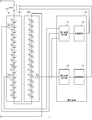
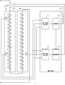
図2は、本発明の実施の形態1に係る蓄電システム1の回路構成を示す図である。実施の形態1に係る蓄電システム1は、直列接続された第1蓄電モジュールM1と第2蓄電モジュールM2で形成される蓄電部20と、蓄電部20を管理する管理装置10を備える。管理装置10は、第1温度検出部11、第2温度検出部12、主制御部13及び副制御部14を含む。第1温度検出部11及び主制御部13は主制御系を形成し、第2温度検出部12及び副制御部14は冗長系を形成する。
高温検出用の第1サーミスタT1及び低温検出用の第3サーミスタT3は、主制御系の温度検出素子であり、第1温度検出部11に接続される。第1温度検出部11は、第1サーミスタT1の出力値と第3サーミスタT3の出力値をもとに、蓄電部20の高温エリアの温度と低温エリアの温度を検出し、主制御部13に出力する。第1温度検出部11は例えば、分圧抵抗、アンプ、AD変換器を含んで構成される。
主制御部13は、第1温度検出部11により検出された高温エリアの温度と低温エリアの温度、図示しない電圧検出部により検出された各セルの電圧、図示しない電流検出部により検出された蓄電部20に流れる電流をもとに、蓄電部20の充放電を制御する。主制御部13の構成は、ハードウェア資源とソフトウェア資源の協働、またはハードウェア資源のみにより実現できる。ハードウェア資源として、マイクロコンピュータ、DSP、FPGA、その他のLSIを利用できる。ソフトウェア資源としてファームウェア等のプログラムを利用できる。
主制御部13は、過電圧、過小電圧、過電流、高温異常、または低温異常を検出すると、蓄電部20と、図示しない負荷との間に挿入されたスイッチSW1をターンオフして、充放電を停止させる。スイッチSW1には、リレーや半導体スイッチを使用することができる。また主制御部13は、SOC(State Of Charge)管理、SOH(State Of Health)管理、均等化制御などを実行する。
高温検出用の第2サーミスタT2は冗長系の温度検出素子であり、第2温度検出部12に接続される。第2温度検出部12は、第2サーミスタT2の出力値をもとに、蓄電部20の高温エリアの温度を検出し、副制御部14に出力する。第2温度検出部12も例えば、分圧抵抗、アンプ、AD変換器を含んで構成される。
副制御部14は、第2温度検出部12により検出された蓄電部20の高温エリアの温度をもとに蓄電部20の充放電を制御する。実施の形態1では、副制御部14は高温異常時の制御に特化しており、第2温度検出部12の検出温度が、高温異常判定用の閾値を超えたときスイッチSW1をターンオフに制御する単純なハードウェア回路で構成される。
上述のように蓄電部20の高温異常は、発煙・発火のリスクが高まる最も危険な事象であり、冗長化の必要性が高い。主制御系に異常が発生し、主制御系の動作が停止した場合でも、蓄電部20に高温異常が発生した場合、冗長系によりスイッチSW1をターンオフするように設計する必要がある。
主制御部13で判定する温度範囲より、副制御部14で判定する温度範囲の上限を高めに設定して、常に主制御部13が副制御部14より優先的に動作するようにしている。例えば、上限温度を主制御部13では65℃、副制御部14では68℃として、高温異常時には主制御部13が副制御部14よりも先に異常検出して、スイッチSW1をターンオフする。また副制御部14は、主制御部13が正常に動作しているとき動作を停止していてもよい。この場合、副制御部14は、主制御部13から動作停止信号を受信すると、自己によるスイッチSW1の制御を有効化し、第2温度検出部12の検出温度が、高温異常判定用の閾値を超えたときスイッチSW1をターンオフに制御する。
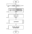
図3は、実施の形態1に係る主制御部13の動作を示すフローチャートである。主制御部13は、第1温度検出部11から第1サーミスタT1の設置位置の第1温度t1と第3サーミスタT3の設置位置の第3温度t3を取得し、第2温度検出部12から第2サーミスタT2の設置位置の第2温度t2を取得する(S10)。
主制御部13は、第1温度t1と第2温度t2との第1差分温度Δ1、第1温度t1と第3温度t3との第2差分温度Δ2、及び第2温度t2と第3温度t3との第3差分温度Δ3をそれぞれ算出する(S11)。なお、これらの差分は、第1温度t1~第3温度t3が充放電温度範囲を逸脱しているか否かに関わらず、常時算出してもよいし、第1温度t1及び第3温度t3の少なくとも一方の値が充放電温度範囲を逸脱しているとき算出してもよい。
主制御部13は、第1温度t1、第2温度t2、第3温度t3、第1差分温度Δ1、第2差分温度Δ2、及び第3差分温度Δ3をもとに、蓄電部20の最高温度と最低温度を特定する(S12)。この温度特定処理は、第1サーミスタT1と第1温度検出部11の故障判定処理も兼ねる。この故障判定処理では、第1サーミスタT1に接続された配線の故障、及び第1温度検出部11に接続された配線の故障も検出される。主制御部13は、特定した最高温度と最低温度をもとに、蓄電部20に対する各種の制御を実行する(S13)。
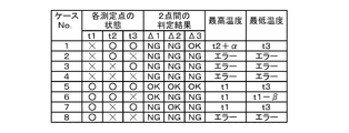
図4は、図3のステップS12の温度特定処理において参照する参照テーブルを示す図である。図4に示すように第1温度t1、第2温度t2及び第3温度t3の内、2つ以上の温度が異常値の場合(ケース2、3、4、8)、第1差分温度Δ1、第2差分温度Δ2及び第3差分温度Δ3の全てが許容値を超える異常値(NG)となる。この場合、主制御部13は、蓄電部20の最高温度と最低温度を特定することができず、エラーを出力し、スイッチSW1をターンオフする。当該エラーは、副制御部14にも通知される。
第1温度t1、第2温度t2及び第3温度t3の全てが正常値の場合(ケース5)、第1差分温度Δ1、第2差分温度Δ2及び第3差分温度Δ3の全てが正常値(OK)となる。この場合、主制御部13は、第1温度t1を蓄電部20の最高温度に設定し、第3温度t3を蓄電部20の最低温度に設定する。
第1温度t1及び第3温度t3が正常値で第2温度t2が異常値の場合(ケース7)、第1差分温度Δ1及び第3差分温度Δ3が異常値(NG)で第2差分温度Δ2が正常値(OK)となる。この場合、主制御部13は、第1温度t1を蓄電部20の最高温度に設定し、第3温度t3を蓄電部20の最低温度に設定する。ケース7は、冗長化している第2サーミスタT2の異常であり、主制御系に異常が発生しているわけではないため、ケース5と同様に扱う。
第2温度t2及び第3温度t3が正常値で第1温度t1が異常値の場合(ケース1)、第1差分温度Δ1及び第2差分温度Δ2が異常値(NG)で第3差分温度Δ3が正常値(OK)となる。この場合、主制御部13は、第2温度t2に偏差αを加算した温度を蓄電部20の最高温度に設定し、第3温度t3を蓄電部20の最低温度に設定する。
偏差αは、定常時の第1温度t1と第2温度t2の誤差を測定した値である。当該誤差は、サーミスタ、アンプ、AD変換器等の素子バラツキに起因する測定誤差と、第1サーミスタT1と第2サーミスタT2の設置位置の違いに起因する温度誤差を加算した値である。なお設置位置の違いに起因する温度誤差がない場合は、素子バラツキに起因する測定誤差が偏差αとなる。
第1温度t1及び第2温度t2が正常値で第3温度t3が異常値の場合(ケース6)、第1差分温度Δ1が正常値(OK)で第2差分温度Δ2及び第3差分温度Δ3が異常値(NG)となる。この場合、主制御部13は、第2温度t2を蓄電部20の最高温度に設定し、第1温度t1から、第1温度t1と第3温度t3の温度差の推定値βを減算した温度を蓄電部20の最低温度に設定する。温度差の推定値βは、定常時に測定した第1温度t1と第3温度t3の最大温度差を使用してもよいし、定常時に測定した両者の平均温度差を使用してもよい。
図5は、実施の形態1に係る副制御部14の動作を示すフローチャートである。副制御部14は、第2温度検出部12から第2サーミスタT2の設置位置の第2温度t2を取得する(S21)。副制御部14は、第2温度t2をもとに、蓄電部20の高温異常時の制御を実行する(S22)。
以上説明したように実施の形態1によれば、蓄電部20に高温検出用の第1サーミスタT1と第2サーミスタT2、及び低温検出用の第3サーミスタT3の3つのサーミスタを設置することにより、蓄電部20の温度制御系を、安全性を確保しつつ低コストで実現することができる。サーミスタの設置数を3つに抑えることにより、コストを低減することができる。その際、高温検出用のサーミスタを二重化し、高温検出用の第2サーミスタT2を、主制御系(第1温度検出部11及び主制御部13)と独立した冗長系(第2温度検出部12及び副制御部14)に接続することにより、安全性を担保することができる。また冗長系を、高温異常時の制御のバックアップに特化させることにより、副制御部14のコストを低減することができる。
また、高温検出用の第2サーミスタT2の出力を主制御系にも出力することにより、第1サーミスタT1または第3サーミスタT3が故障した場合でも、主制御部13による温度制御を継続させることができる。図4に示したように3つの差分温度の1つが正常値の場合、3つのサーミスタの2つが正常であることを示している(ケース1、6、7)。第1サーミスタT1と第3サーミスタT3の2つが正常で、バックアップ用の第2サーミスタT2が異常な場合(ケース7)、第1サーミスタT1と第3サーミスタT3の測定値をそのまま使用する。
第2サーミスタT2と第3サーミスタT3の2つが正常で、第1サーミスタT1が異常な場合(ケース1)、バックアップ用の第2サーミスタT2の測定値に偏差αを加算して、第1サーミスタT1の測定値の代替値として使用する。これにより、第1サーミスタT1の故障により、蓄電部20の充放電動作が停止することを回避することができる。
第1サーミスタT1と第2サーミスタT2の2つが正常で、第3サーミスタT3が異常な場合(ケース6)、第1サーミスタT1の測定値から温度差の推定値βを減算して、第3サーミスタT3の測定値の代替値として使用する。これにより、第3サーミスタT3の故障により、蓄電部20の充放電動作が停止することを回避することができる。
なお、第1サーミスタT1の第1温度t1が正常であれば、第1温度t1と第2サーミスタT2の第2温度t2との第1差分温度Δ1の正常/異常を判定することなく、第1サーミスタT1の測定値から温度差の推定値βを減算して、第3サーミスタT3の測定値の代替値として使用することも考えられる。ただしこの場合、蓄電部20の最高温度と最低温度が第1サーミスタT1の第1温度t1のみを根拠とすることになり、安全性の観点から好ましくない。これに対して第1差分温度Δ1の正常を確認することにより、第1サーミスタT1が正常であるとの判断がより強固になり、第1サーミスタT1の測定値から温度差の推定値βを減算した値を、最低温度として使用することが許容される。
図6は、本発明の実施の形態2に係る蓄電システム1の回路構成を示す図である。実施の形態2に係る蓄電システム1では、副制御部14に、主制御部13と同一または略同等の制御部を使用し、副制御部14が、主制御部13の全てまたは略全ての制御をバックアップする。実施の形態2では、高温検出用の第1サーミスタT1及び低温検出用の第3サーミスタT3が、第2温度検出部12にも接続される。実施の形態2に係る主制御部13の動作は、図3のフローチャートに示した実施の形態1に係る主制御部13の動作と同じである。
図7は、実施の形態2に係る副制御部14の動作を示すフローチャートである。副制御部14は、主制御部13に異常が発生しているか否か判定する(S20)。この異常には主制御部13自体の異常に加えて、主制御部13とスイッチSW1間の配線の異常、温度検出異常が含まれる。温度検出異常は、上記図4のケース2、3、4、8のケースである。主制御部13に異常が発生している場合(S20のY)、図3の主制御部13によるステップS10-S13の処理と同様の処理を実行する。
即ち、副制御部14は、第1温度検出部11から第1サーミスタT1の設置位置の第1温度t1と第3サーミスタT3の設置位置の第3温度t3を取得し、第2温度検出部12から第2サーミスタT2の設置位置の第2温度t2を取得する(S10)。副制御部14は、第1温度t1と第2温度t2との第1差分温度Δ1、第1温度t1と第3温度t3との第2差分温度Δ2、及び第2温度t2と第3温度t3との第3差分温度Δ3をそれぞれ算出する(S11)。副制御部14は、第1温度t1、第2温度t2、第3温度t3、第1差分温度Δ1、第2差分温度Δ2、及び第3差分温度Δ3をもとに、蓄電部20の最高温度と最低温度を特定する(S12)。副制御部14は、特定した最高温度と最低温度をもとに、蓄電部20に対する各種の制御を実行する(S13)。
なお、副制御部14は図4に示した参照テーブルをもとに、ステップS12の温度特定処理を実行してもよいし、図4の第1温度t1と第2温度t2を入れ替えた参照テーブルをもとに、ステップS12の温度特定処理を実行してもよい。
以上説明したように実施の形態2によれば、3つのサーミスタを用いて実施の形態1と比較して、よりリッチなバックアップを実現することができる。即ち、主制御部13に異常が発生しても、主制御部13による制御と同等の制御を副制御部14が実行することができる。
以上、本発明を実施の形態をもとに説明した。実施の形態は例示であり、それらの各構成要素や各処理プロセスの組み合わせにいろいろな変形例が可能なこと、またそうした変形例も本発明の範囲にあることは当業者に理解されるところである。
上述の実施の形態では、第1蓄電モジュールM1と第2蓄電モジュールM2の2つの蓄電モジュールを含む蓄電部の温度制御を説明した。この点、1つの蓄電モジュールを含む蓄電部20の温度制御にも適用可能である。例えば、第1蓄電モジュールM1の第12セルS12の近傍に高温検出用の第1サーミスタT1を設置し、第1蓄電モジュールM1の第11セルS11の近傍に高温検出用の第2サーミスタT2を設置し、第1蓄電モジュールM1の第2セルS2の近傍に低温検出用の第3サーミスタT3を設置する。主制御系、冗長系の回路構成は上述の実施の形態と同様である。
またケース内の温度が比較的均一な用途では、3つ以上の蓄電モジュールを含む蓄電部の温度制御にも適用可能である。
なお、実施の形態は、以下の項目によって特定されてもよい。
[項目1]
複数のセル(S1-S16)を含む蓄電部(20)を管理する管理装置(10)であって、
前記蓄電部(20)の高温エリアの第1の箇所に設置される高温検出用の第1温度検出素子(T1)と、前記蓄電部(20)の低温エリアの所定の箇所に設置される低温検出用の温度検出素子(T3)の出力値をもとに、前記蓄電部(20)の高温エリアの温度と低温エリアの温度を検出する第1温度検出部(11)と、
前記第1温度検出部(11)により検出された高温エリアの温度と低温エリアの温度をもとに、前記蓄電部(20)の充放電を制御する主制御部(13)と、
前記蓄電部(20)の高温エリアの第2の箇所に設置される高温検出用の第2温度検出素子(T2)の出力値をもとに、前記蓄電部(20)の高温エリアの温度を検出する第2温度検出部(12)と、
前記主制御部(13)に異常が発生したとき、前記第2温度検出部(12)により検出された高温エリアの温度をもとに前記蓄電部(20)の充放電を制御する副制御部(14)と、
を備え、
前記高温検出用の第2温度検出素子(T2)の出力値は、前記第1温度検出部(11)にも出力されており、
前記主制御部(13)は、前記高温検出用の第1温度検出素子(T1)の出力値と前記高温検出用の第2温度検出素子(T2)の出力値との第1差分、前記高温検出用の第1温度検出素子(T1)の出力値と前記低温検出用の温度検出素子(T3)の出力値との第2差分、及び前記高温検出用の第2温度検出素子(T2)の出力値と前記低温検出用の温度検出素子(T3)の出力値との第3差分をそれぞれ算出し、前記第1差分および前記第2差分が異常値で前記第3差分が正常値のとき、前記高温検出用の第2温度検出素子(T2)の出力値に、前記高温検出用の第1温度検出素子(T1)の出力値との定常時の偏差を加算して、前記蓄電部(20)の高温エリアの温度の代替値として使用する、
ことを特徴とする管理装置(10)。
これによれば、蓄電部(20)の温度制御系を、安全性を確保しつつ低コストで実現することができる。また、主制御部(13)による温度制御が、できるだけ停止しない設計を実現することができる。
[項目2]
前記主制御部(13)は、前記第2差分および前記第3差分が異常値で前記第1差分が正常値のとき、前記高温検出用の第1温度検出素子(T1)の出力値から、前記蓄電部(20)内の高温エリアの温度と低温エリアの温度の温度差の推定値を減算して、前記蓄電部(20)の低温エリアの温度の代替値として使用する、ことを特徴とする項目1に記載の管理装置(10)。
これによれば、主制御部(13)による温度制御が、できるだけ停止しない設計を実現することができる。
[項目3]
前記高温検出用の第1温度検出素子(T1)の出力値および前記低温検出用の温度検出素子(T3)の出力値は、前記第2温度検出部(12)にも出力されており、
前記副制御部(14)は、前記第1差分、前記第2差分、及び前記第3差分をそれぞれ算出し、前記第1差分および前記第2差分が異常値で前記第3差分が正常値のとき、前記高温検出用の第2温度検出素子(T2)の出力値に、前記高温検出用の第1温度検出素子の出力値(T1)との定常時の偏差を加算して、前記蓄電部(20)の高温エリアの温度の代替値として使用する、ことを特徴とする項目1または2に記載の管理装置(10)。
これによれば、主制御部(13)に異常が発生しても、主制御部(13)の制御と同等の制御を、副制御部(14)により実現することができる。
[項目4]
前記蓄電部(20)は、複数のセル(S1-S16)を含む第1蓄電モジュール(M1)と、複数のセル(S1-S16)を含む第2蓄電モジュール(M2)が接続されて形成され、
前記高温検出用の第1温度検出素子(T1)は、前記第1蓄電モジュール(M1)の高温エリアに設置され、
前記高温検出用の第2温度検出素子(T2)は、前記第2蓄電モジュール(M2)の高温エリアに設置され、
前記低温検出用の温度検出素子(T3)は、前記第1蓄電モジュール(M1)の低温エリアに設置される、
ことを特徴とする項目1から3のいずれかに記載の管理装置(10)。
これによれば、3つの温度検出素子(T1、T2、T3)で、2つの蓄電モジュールを含む蓄電部(20)の温度制御を、安全性を確保しつつ実現することができる。
[項目5]
蓄電部(20)と、
前記蓄電部(20)を管理する項目1から4のいずれかに記載の管理装置(10)と、
を備えることを特徴とする蓄電システム(1)。
これによれば、蓄電システム(1)の蓄電部(20)の温度制御系を、安全性を確保しつつ低コストで実現することができる。また、主制御部(13)による温度制御が、できるだけ停止しない設計を実現することができる。
1 蓄電システム、 2a,2b エンドプレート、 3a,3b バインドプレート、 4 吸気口、 5 排気口、 M1 第1蓄電モジュール、 M2 第2蓄電モジュール、 S1 第1セル、 S4 第4セル、 S12 第12セル、 S16 第16セル、 T1 第1サーミスタ、 T2 第2サーミスタ、 T3 第3サーミスタ、 SW1 スイッチ、 10 管理装置、 11 第1温度検出部、 12 第2温度検出部、 13 主制御部、 14 副制御部、 20 蓄電部。
Claims (5)
- 複数のセルを含む蓄電部を管理する管理装置であって、
前記蓄電部の高温エリアの第1の箇所に設置される高温検出用の第1温度検出素子と、前記蓄電部の低温エリアの所定の箇所に設置される低温検出用の温度検出素子の出力値をもとに、前記蓄電部の高温エリアの温度と低温エリアの温度を検出する第1温度検出部と、
前記第1温度検出部により検出された高温エリアの温度と低温エリアの温度をもとに、前記蓄電部の充放電を制御する主制御部と、
前記蓄電部の高温エリアの第2の箇所に設置される高温検出用の第2温度検出素子の出力値をもとに、前記蓄電部の高温エリアの温度を検出する第2温度検出部と、
前記主制御部に異常が発生したとき、前記第2温度検出部により検出された高温エリアの温度をもとに前記蓄電部の充放電を制御する副制御部と、
を備え、
前記高温検出用の第2温度検出素子の出力値は、前記第1温度検出部にも出力されており、
前記主制御部は、前記高温検出用の第1温度検出素子の出力値と前記高温検出用の第2温度検出素子の出力値との第1差分、前記高温検出用の第1温度検出素子の出力値と前記低温検出用の温度検出素子の出力値との第2差分、及び前記高温検出用の第2温度検出素子の出力値と前記低温検出用の温度検出素子の出力値との第3差分をそれぞれ算出し、前記第1差分および前記第2差分が異常値で前記第3差分が正常値のとき、前記高温検出用の第2温度検出素子の出力値に、前記高温検出用の第1温度検出素子の出力値との定常時の偏差を加算して、前記蓄電部の高温エリアの温度の代替値として使用する、
ことを特徴とする管理装置。 - 前記主制御部は、前記第2差分および前記第3差分が異常値で前記第1差分が正常値のとき、前記高温検出用の第1温度検出素子の出力値から、前記蓄電部内の高温エリアの温度と低温エリアの温度の温度差の推定値を減算して、前記蓄電部の低温エリアの温度の代替値として使用する、
ことを特徴とする請求項1に記載の管理装置。 - 前記高温検出用の第1温度検出素子の出力値および前記低温検出用の温度検出素子の出力値は、前記第2温度検出部にも出力されており、
前記副制御部は、前記第1差分、前記第2差分、及び前記第3差分をそれぞれ算出し、前記第1差分および前記第2差分が異常値で前記第3差分が正常値のとき、前記高温検出用の第2温度検出素子の出力値に、前記高温検出用の第1温度検出素子の出力値との定常時の偏差を加算して、前記蓄電部の高温エリアの温度の代替値として使用する、
ことを特徴とする請求項1または2に記載の管理装置。 - 前記蓄電部は、複数のセルを含む第1蓄電モジュールと、複数のセルを含む第2蓄電モジュールが接続されて形成され、
前記高温検出用の第1温度検出素子は、前記第1蓄電モジュールの高温エリアに設置され、
前記高温検出用の第2温度検出素子は、前記第2蓄電モジュールの高温エリアに設置され、
前記低温検出用の温度検出素子は、前記第1蓄電モジュールの低温エリアに設置される、
ことを特徴とする請求項1から3のいずれかに記載の管理装置。 - 蓄電部と、
前記蓄電部を管理する請求項1から4のいずれかに記載の管理装置と、
を備えることを特徴とする蓄電システム。
Priority Applications (3)
| Application Number | Priority Date | Filing Date | Title |
|---|---|---|---|
| JP2018536933A JP6790102B2 (ja) | 2016-08-30 | 2017-05-09 | 管理装置、及び蓄電システム |
| US16/325,320 US10923934B2 (en) | 2016-08-30 | 2017-05-09 | Management device and power storage system |
| CN201780046892.0A CN109565087B (zh) | 2016-08-30 | 2017-05-09 | 管理装置和蓄电系统 |
Applications Claiming Priority (2)
| Application Number | Priority Date | Filing Date | Title |
|---|---|---|---|
| JP2016-168511 | 2016-08-30 | ||
| JP2016168511 | 2016-08-30 |
Publications (1)
| Publication Number | Publication Date |
|---|---|
| WO2018042764A1 true WO2018042764A1 (ja) | 2018-03-08 |
Family
ID=61309374
Family Applications (1)
| Application Number | Title | Priority Date | Filing Date |
|---|---|---|---|
| PCT/JP2017/017453 Ceased WO2018042764A1 (ja) | 2016-08-30 | 2017-05-09 | 管理装置、及び蓄電システム |
Country Status (4)
| Country | Link |
|---|---|
| US (1) | US10923934B2 (ja) |
| JP (1) | JP6790102B2 (ja) |
| CN (1) | CN109565087B (ja) |
| WO (1) | WO2018042764A1 (ja) |
Cited By (4)
| Publication number | Priority date | Publication date | Assignee | Title |
|---|---|---|---|---|
| CN110715735A (zh) * | 2018-07-13 | 2020-01-21 | 宁德新能源科技有限公司 | 温度测量方法、温度测量系统、电子装置及可读存储介质 |
| JP2020038076A (ja) * | 2018-09-03 | 2020-03-12 | トヨタ自動車株式会社 | 蓄電システム |
| JP2021136050A (ja) * | 2020-02-21 | 2021-09-13 | 株式会社デンソー | 電池パック |
| JP2024151160A (ja) * | 2023-04-11 | 2024-10-24 | プライムプラネットエナジー&ソリューションズ株式会社 | 蓄電モジュールおよびその製造方法 |
Families Citing this family (1)
| Publication number | Priority date | Publication date | Assignee | Title |
|---|---|---|---|---|
| JP7055573B2 (ja) * | 2018-09-13 | 2022-04-18 | アルパイン株式会社 | 電子機器、電子機器処理方法および電子機器処理プログラム |
Citations (4)
| Publication number | Priority date | Publication date | Assignee | Title |
|---|---|---|---|---|
| JP2007109536A (ja) * | 2005-10-14 | 2007-04-26 | Toyota Motor Corp | 温度検知装置 |
| JP2013099167A (ja) * | 2011-11-02 | 2013-05-20 | Toyota Motor Corp | 蓄電システムを搭載した車両の制御装置及び制御方法 |
| JP2014107979A (ja) * | 2012-11-28 | 2014-06-09 | Denso Corp | 電池監視装置 |
| JP2014131452A (ja) * | 2012-12-28 | 2014-07-10 | Sharp Corp | 充電制御装置、充電制御プログラムおよび携帯端末 |
Family Cites Families (12)
| Publication number | Priority date | Publication date | Assignee | Title |
|---|---|---|---|---|
| US5637982A (en) * | 1991-06-17 | 1997-06-10 | Kabushiki Kaisha Toshiba | Method and system for detecting full charge of a rechargeable battery in a portable computer system |
| US7145314B2 (en) * | 2003-05-23 | 2006-12-05 | Hitachi Koki Co., Ltd. | DC power source unit with battery charging function |
| JP4455461B2 (ja) * | 2005-09-12 | 2010-04-21 | 株式会社東芝 | 蓄電システム |
| JP5196936B2 (ja) * | 2007-09-27 | 2013-05-15 | 三洋電機株式会社 | 車両用の電源装置 |
| JP5486780B2 (ja) * | 2008-07-01 | 2014-05-07 | 株式会社日立製作所 | 電池システム |
| JP5533175B2 (ja) * | 2009-05-20 | 2014-06-25 | 日産自動車株式会社 | 組電池監視装置 |
| JPWO2011024477A1 (ja) * | 2009-08-31 | 2013-01-24 | 三洋電機株式会社 | バッテリモジュール、バッテリシステムおよび電動車両 |
| CN102549348B (zh) * | 2010-07-07 | 2014-07-23 | 松下电器产业株式会社 | 储热水式供热水系统及其运转方法 |
| KR101189885B1 (ko) * | 2010-10-19 | 2012-10-10 | 산요덴키가부시키가이샤 | 전원 장치 및 이를 사용한 차량 및 축전 장치 |
| JP2014164812A (ja) | 2013-02-21 | 2014-09-08 | Toyota Industries Corp | 蓄電装置モジュール |
| JP5939269B2 (ja) * | 2014-03-19 | 2016-06-22 | トヨタ自動車株式会社 | 電池の劣化判定装置 |
| CN104979594B (zh) * | 2014-04-02 | 2018-02-09 | 比亚迪股份有限公司 | 动力电池的控制方法及系统 |
-
2017
- 2017-05-09 US US16/325,320 patent/US10923934B2/en active Active
- 2017-05-09 CN CN201780046892.0A patent/CN109565087B/zh active Active
- 2017-05-09 WO PCT/JP2017/017453 patent/WO2018042764A1/ja not_active Ceased
- 2017-05-09 JP JP2018536933A patent/JP6790102B2/ja active Active
Patent Citations (4)
| Publication number | Priority date | Publication date | Assignee | Title |
|---|---|---|---|---|
| JP2007109536A (ja) * | 2005-10-14 | 2007-04-26 | Toyota Motor Corp | 温度検知装置 |
| JP2013099167A (ja) * | 2011-11-02 | 2013-05-20 | Toyota Motor Corp | 蓄電システムを搭載した車両の制御装置及び制御方法 |
| JP2014107979A (ja) * | 2012-11-28 | 2014-06-09 | Denso Corp | 電池監視装置 |
| JP2014131452A (ja) * | 2012-12-28 | 2014-07-10 | Sharp Corp | 充電制御装置、充電制御プログラムおよび携帯端末 |
Cited By (7)
| Publication number | Priority date | Publication date | Assignee | Title |
|---|---|---|---|---|
| CN110715735A (zh) * | 2018-07-13 | 2020-01-21 | 宁德新能源科技有限公司 | 温度测量方法、温度测量系统、电子装置及可读存储介质 |
| JP2020038076A (ja) * | 2018-09-03 | 2020-03-12 | トヨタ自動車株式会社 | 蓄電システム |
| JP7087846B2 (ja) | 2018-09-03 | 2022-06-21 | トヨタ自動車株式会社 | 蓄電システム |
| JP2021136050A (ja) * | 2020-02-21 | 2021-09-13 | 株式会社デンソー | 電池パック |
| JP7302501B2 (ja) | 2020-02-21 | 2023-07-04 | 株式会社デンソー | 電池パック |
| JP2024151160A (ja) * | 2023-04-11 | 2024-10-24 | プライムプラネットエナジー&ソリューションズ株式会社 | 蓄電モジュールおよびその製造方法 |
| JP7699623B2 (ja) | 2023-04-11 | 2025-06-27 | プライムプラネットエナジー&ソリューションズ株式会社 | 蓄電モジュールおよびその製造方法 |
Also Published As
| Publication number | Publication date |
|---|---|
| JP6790102B2 (ja) | 2020-11-25 |
| JPWO2018042764A1 (ja) | 2019-06-24 |
| CN109565087A (zh) | 2019-04-02 |
| US20190207404A1 (en) | 2019-07-04 |
| US10923934B2 (en) | 2021-02-16 |
| CN109565087B (zh) | 2021-11-26 |
Similar Documents
| Publication | Publication Date | Title |
|---|---|---|
| JP6790102B2 (ja) | 管理装置、及び蓄電システム | |
| CN103703646B (zh) | 故障诊断方法、系统互连装置和控制装置 | |
| US9673640B2 (en) | Battery system monitoring apparatus and electric storage device including the same for balancing a plurality of battery cells by discharging them based on voltage dependent turn-on resistance adapting of the balancing switch | |
| JP5819443B2 (ja) | 電池制御装置、電池システム | |
| US20200212507A1 (en) | Electricity storage system and management device | |
| KR102553037B1 (ko) | 배터리 전압 데이터를 이용한 이상 상태 사전 감지 시스템 | |
| CN107887659A (zh) | 蓄电装置、蓄电系统、蓄电装置的状态判定方法 | |
| WO2012049965A1 (ja) | 電力管理システム | |
| WO2015181866A1 (ja) | 電池システム | |
| JP2019518212A (ja) | 電圧分配を用いたスイッチ診断装置及び方法 | |
| KR20210036053A (ko) | 배터리 온도 데이터를 이용한 이상 상태 사전 감지 시스템 | |
| WO2017090156A1 (ja) | 電力制御装置、および電力制御システム | |
| WO2016143296A1 (ja) | 蓄電制御システム及び充放電制御方法 | |
| JP7284911B2 (ja) | 蓄電素子の管理装置、システム、及び、蓄電素子の管理方法 | |
| US9941714B2 (en) | Battery system and motor vehicle with battery system | |
| KR101856067B1 (ko) | 배터리 관리 시스템의 센싱 정밀도 진단 장치 및 방법 | |
| CN105518926A (zh) | 用于运行本质安全的电池组电池的方法 | |
| KR102852055B1 (ko) | 다병렬 충/방전 fet 구조의 고장 진단 회로 및 그 진단 방법 | |
| JP2022102034A (ja) | 蓄電システム、および蓄電システムの制御装置 | |
| JP2013146159A (ja) | 組電池の充電制御システムおよび充電制御方法 | |
| US20250035707A1 (en) | Battery Diagnosis Apparatus And Method For Leakage Current Detection | |
| JP7661953B2 (ja) | 蓄電システム | |
| JP6589669B2 (ja) | 温度監視装置 | |
| JP2011160639A (ja) | 瞬低対策装置 | |
| KR20260062831A (ko) | 전지 시스템 |
Legal Events
| Date | Code | Title | Description |
|---|---|---|---|
| 121 | Ep: the epo has been informed by wipo that ep was designated in this application |
Ref document number: 17845775 Country of ref document: EP Kind code of ref document: A1 |
|
| ENP | Entry into the national phase |
Ref document number: 2018536933 Country of ref document: JP Kind code of ref document: A |
|
| NENP | Non-entry into the national phase |
Ref country code: DE |
|
| 122 | Ep: pct application non-entry in european phase |
Ref document number: 17845775 Country of ref document: EP Kind code of ref document: A1 |