WO2018042549A1 - 被写体情報表示システム、被写体情報表示方法及びプログラム - Google Patents
被写体情報表示システム、被写体情報表示方法及びプログラム Download PDFInfo
- Publication number
- WO2018042549A1 WO2018042549A1 PCT/JP2016/075483 JP2016075483W WO2018042549A1 WO 2018042549 A1 WO2018042549 A1 WO 2018042549A1 JP 2016075483 W JP2016075483 W JP 2016075483W WO 2018042549 A1 WO2018042549 A1 WO 2018042549A1
- Authority
- WO
- WIPO (PCT)
- Prior art keywords
- subject
- information
- store visit
- information display
- terminal
- Prior art date
- Legal status (The legal status is an assumption and is not a legal conclusion. Google has not performed a legal analysis and makes no representation as to the accuracy of the status listed.)
- Ceased
Links
Images








Classifications
-
- G—PHYSICS
- G06—COMPUTING OR CALCULATING; COUNTING
- G06Q—INFORMATION AND COMMUNICATION TECHNOLOGY [ICT] SPECIALLY ADAPTED FOR ADMINISTRATIVE, COMMERCIAL, FINANCIAL, MANAGERIAL OR SUPERVISORY PURPOSES; SYSTEMS OR METHODS SPECIALLY ADAPTED FOR ADMINISTRATIVE, COMMERCIAL, FINANCIAL, MANAGERIAL OR SUPERVISORY PURPOSES, NOT OTHERWISE PROVIDED FOR
- G06Q30/00—Commerce
- G06Q30/06—Buying, selling or leasing transactions
Definitions
- the present invention relates to a subject information display system, a subject information display method, and a program for managing the usage status of customers visiting or visiting various facilities such as restaurants, hotels, event venues, and stores.
- a store visit status management system in which a customer's visit status is managed by capturing a face image of a customer passing through an entrance and analyzing the captured face image.
- Patent Document 1 since the configuration of Patent Document 1 is only for managing the visit of a customer, it is difficult to grasp various personal information such as the name, age, and gender of the customer. For this reason, customers receive different services for each service provider, and it is difficult to reduce the difference in service provider capabilities.
- An object of the present invention is to provide a subject information display system, a subject information display method, and a program capable of reducing a capability difference of a service provider by detecting and displaying attribute information and store visit information of a customer who is a subject.
- the purpose is to provide.
- the present invention provides the following solutions.
- the invention according to the first feature is a captured image acquisition means for acquiring a captured image of a subject captured by a camera; Image analysis means for image analysis of the acquired captured image; Subject specifying means for specifying the subject based on the result of the image analysis; Attribute information detection means for detecting attribute information of the identified subject; Attribute information display means for displaying the detected attribute information on a terminal; Store visit information detecting means for detecting store visit information of the identified subject; Store visit information display means for displaying the detected store visit information on a terminal; An object information display system is provided.
- a captured image of a subject captured by a camera is acquired, the acquired captured image is subjected to image analysis, and the subject is identified based on the image analysis result.
- the attribute information of the identified subject is detected, the detected attribute information is displayed on the terminal, the store visit information of the identified subject is detected, and the detected store visit information is displayed on the terminal.
- the invention according to the first feature is the category of the subject information display system, but the same operation and effect corresponding to the category are exhibited in other categories such as a method or a program.
- the invention according to the second feature is a notification means for notifying the terminal when the identified subject is a regular customer or a customer of a first visit.
- a subject information display system that is an invention according to a first feature is provided.
- the subject information display system notifies the terminal when the specified subject is a regular customer or a first-time customer. .
- the invention according to a third feature is a notification means for notifying the terminal when the identified subject is a suspicious person;
- a subject information display system that is an invention according to a first feature is provided.
- the subject information display system notifies the terminal when the specified subject is a suspicious person.
- the invention according to a fourth feature provides a subject information display system according to the first feature, wherein the attribute information is an age and sex of the subject.
- the attribute information is the age and sex of the subject.
- the invention according to a fifth feature provides a subject information display system according to the first feature, wherein the store visit information is the number of visits to the subject and the store visit frequency.
- the store visit information includes the number of visits to the subject and the store visit frequency.
- the invention according to a sixth feature is subject information according to the fifth feature, wherein the store visit information display means displays the number of visits to the subject and the store visit frequency in a predetermined period in a graph. Provide a display system.
- the subject information display system displays the number of visits and the visit frequency of the subject in a predetermined period in a graph.
- the invention according to a seventh aspect includes a step of acquiring a captured image of a subject captured by a camera; Analyzing the acquired captured image; and Identifying the subject based on the image analysis results; Detecting attribute information of the identified subject; Displaying the detected attribute information on a terminal; Detecting store visit information of the identified subject; Displaying the detected store visit information on a terminal;
- a subject information display method characterized by comprising:
- the invention according to the eighth feature provides a subject information display system, Obtaining a captured image of a subject imaged by a camera; Image analysis of the acquired captured image; Identifying the subject based on the image analysis result; Detecting attribute information of the identified subject; Displaying the detected attribute information on a terminal; Detecting store visit information of the identified subject; Displaying the detected store visit information on a terminal; Provide a program to execute.
- the present invention it is possible to provide a subject information display system, a subject information display method, and a program that can reduce the difference in ability of service providers.
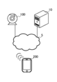
- FIG. 1 is a diagram showing an outline of the subject information display system 1.
- FIG. 2 is an overall configuration diagram of the subject information display system 1.
- FIG. 3 is a functional block diagram of the computer 10, the camera 100, and the terminal 200.
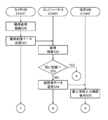
- FIG. 4 is a flowchart of personal information registration processing executed by the computer 10, the camera 100, and the terminal 200.
- FIG. 5 is a flowchart illustrating personal information registration processing executed by the computer 10, the camera 100, and the terminal 200.
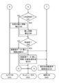
- FIG. 6 is a flowchart of subject information display processing executed by the computer 10, the camera 100, and the terminal 200.
- FIG. 7 is a diagram illustrating a flowchart of subject information display processing executed by the computer 10, the camera 100, and the terminal 200.
- FIG. 1 is a diagram showing an outline of the subject information display system 1.
- FIG. 2 is an overall configuration diagram of the subject information display system 1.
- FIG. 3 is a functional block diagram of the computer 10, the camera 100, and the terminal 200.
- FIG. 4 is a flowchar
- FIG. 8 is a diagram illustrating an example of a personal information input screen displayed on the terminal 200.
- FIG. 9 is a diagram illustrating an example of a personal information input screen in a state where the terminal 200 accepts input of personal information.
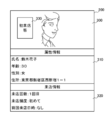
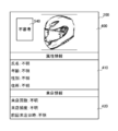
- FIG. 10 is a diagram illustrating an example of a subject information display screen displayed on the terminal 200.
- FIG. 11 is a diagram illustrating an example of a subject information display screen displayed on the terminal 200.
- FIG. 12 is a diagram illustrating an example of a subject information display screen displayed on the terminal 200.
- FIG. 13 is a diagram illustrating an example of a subject information display screen displayed on the terminal 200.
- FIG. 1 is a diagram for explaining an outline of a subject information display system 1 which is a preferred embodiment of the present invention.
- the subject information display system 1 includes a computer 10, a camera 100, and a terminal 200.
- the number of cameras 100 and terminals 200 is not limited to one and may be plural.
- the computer 10 is not limited to an actual device, and may be a virtual device. Each process described below may be realized by any one or a combination of the computer 10, the camera 100, and the terminal 200.
- the computer 10 is a computer device capable of data communication with the camera 100 and the terminal 200.
- the camera 100 is an imaging device that can perform data communication with the computer 10 and capture a moving image, a still image, or the like of a customer as a subject.
- the camera 100 is, for example, an imaging device provided in various portable terminals, or an imaging device provided in a wearable terminal such as a smart glass or a head-mounted display, in addition to a stationary or portable imaging device such as an NW camera or a surveillance camera. It is an imaging device provided in the apparatus and other articles.
- the terminal 200 is a terminal device possessed by a service provider as a user and capable of data communication with the computer 10.
- the terminal 200 is, for example, a mobile phone, a portable information terminal, a tablet terminal, a personal computer, an electronic product such as a netbook terminal, a slate terminal, an electronic book terminal, a portable music player, a smart glass, a head mounted display, or the like. Wearable terminals and other items.
- the camera 100 captures a captured image of a visitor who is the subject (step S01).
- the camera 100 captures an image when a customer comes to a predetermined place.
- the camera 100 images one or more customers.
- the camera 100 transmits captured image data, which is captured image data, to the computer 10 (step S02).
- the computer 10 receives captured image data.
- the computer 10 acquires captured images captured by the camera 100 by receiving captured image data from the camera 100.
- the computer 10 analyzes the captured image data (step S03).
- the computer 10 extracts the customer face image data included in the captured image data using a face recognition technique or the like.
- the computer 10 transmits the extracted face image data to the terminal 200 as a result of the image analysis (step S04).
- Terminal 200 receives face image data.
- the terminal 200 displays a face image based on the face image data and accepts input of the customer's personal information (step S05).
- Personal information refers to, for example, attribute information that indicates customer attributes such as customer name, age, gender, address, occupation, etc., and customer visit status such as the number of customer visits, store visit frequency, and visit date / time.
- the store visit information may not be input by the terminal 200 but may be input by the computer 10 and the terminal 200 may display the information input by the computer 10.
- the terminal 200 transmits the face image data and the personal information that has been accepted to the computer 10 (step S06). Note that the terminal 200 may transmit only personal information without transmitting the face image data.
- the computer 10 receives face image data and personal information.
- the computer 10 stores the face image data and the personal information in association with each other (step S07).
- the subject information display system 1 stores the customer's face image and the customer's personal information in association with each other through the processes of steps S01 to S07.
- the subject information display system 1 uses the stored face image and personal information in the processing after step S08 described later.
- the camera 100 captures a captured image of the customer who visited the store (step S08). This process is the same process as step S01 described above.
- the camera 100 transmits captured image data, which is captured image data, to the computer 10 (step S09).
- the computer 10 receives captured image data.
- the computer 10 acquires captured images captured by the camera 100 by receiving captured image data from the camera 100.
- the computer 10 analyzes the captured image data (step S10).
- the computer 10 extracts the customer face image data included in the captured image data using a face recognition technique or the like.
- the computer 10 specifies the subject based on the result of the image analysis (step S11).
- the computer 10 compares the face image data stored by itself with the face image data extracted this time, thereby extracting from the face image data storing the matching face image data and specifying the subject.
- the computer 10 detects personal information associated with the identified subject (step S12).
- the computer 10 detects the above-described attribute information and store visit information as personal information.
- the computer 10 detects, for example, a name, age, sex, and address as attribute information.
- the computer 10 detects, for example, the number of visits, the visit frequency, and the previous visit date as the store visit information.
- the computer 10 transmits the face image data of the captured image captured by the camera 100 and the detected personal information to the terminal 200 (step S13).
- Terminal 200 receives face image data and personal information.
- the terminal 200 displays a face image based on the face image data and personal information (step S14).
- the terminal 200 displays the above-described attribute information and store visit information as personal information.
- the computer 10 sends a notification to that effect to the terminal 200, and the terminal 200 sends this notification in addition to the display contents described above. It may be displayed.
- the computer 10 may transmit a notification to that effect to the terminal 200, and the terminal 200 may display this notification together with the face image.
- the terminal 200 may display the number of visits to the subject and the visit frequency in a predetermined period in a graph based on the visit information.
- FIG. 2 is a diagram showing a system configuration of a subject information display system 1 which is a preferred embodiment of the present invention.
- the subject information display system 1 includes a computer 10, a camera 100, a terminal 200, and a public line network (Internet network, third and fourth generation communication network, etc.) 5. Note that the number of cameras 100 and terminals 200 is not limited to one and may be plural. Further, the computer 10 is not limited to a real device, and may be a virtual device. In addition, each process described below may be realized by any one or a combination of the computer 10, the camera 100, and the terminal 200.
- the computer 10 is the above-described computer device having the functions described below.
- the camera 100 is the above-described imaging device having the functions described below.
- the terminal 200 is the above-described terminal device having the functions described later.
- FIG. 3 is a functional block diagram of the computer 10, the camera 100, and the terminal 200.
- the computer 10 includes a CPU (Central Processing Unit), a RAM (Random Access Memory), a ROM (Read Only Memory), etc. as the control unit 11, and a device for enabling communication with other devices as the communication unit 12.
- a WiFi (Wireless Fidelity) compatible device compliant with IEEE 802.11 is provided.
- the computer 10 also includes a data storage unit such as a hard disk, a semiconductor memory, a recording medium, or a memory card as the storage unit 13.
- control unit 11 reads a predetermined program, thereby realizing the data transmission / reception module 20 and the data analysis module 21 in cooperation with the communication unit 12.
- control unit 11 reads a predetermined program, thereby realizing the data detection module 30 and the data storage module 31 in cooperation with the storage unit 13.
- the camera 100 includes a CPU, RAM, ROM, and the like as the control unit 110, and a WiFi compatible device for enabling communication with other devices as the communication unit 120.
- the camera 100 includes an imaging device such as an imaging device or a lens as the imaging unit 140.
- the control unit 110 when the control unit 110 reads a predetermined program, the data transmission / reception module 150 is realized in cooperation with the communication unit 120. In the camera 100, the control unit 110 reads a predetermined program, thereby realizing the imaging module 170 in cooperation with the imaging unit 140.
- the terminal 200 includes a CPU, RAM, ROM, and the like as the control unit 210, and a WiFi compatible device for enabling communication with other devices as the communication unit 220. Further, the terminal 200 includes, as the input / output unit 240, a display unit that outputs and displays data and images controlled by the control unit 210, an input unit such as a touch panel, a keyboard, and a mouse that receives input from the user.
- the control unit 210 when the control unit 210 reads a predetermined program, the data transmission / reception module 250 is realized in cooperation with the communication unit 220. In the terminal 200, the control unit 210 reads a predetermined program, thereby realizing the display module 270 and the input reception module 271 in cooperation with the input / output unit 240.
- FIGS. 4 and 5 are flowcharts showing personal information registration processing executed by the computer 10, the camera 100, and the terminal 200.
- FIG. The processing executed by the modules of each device described above will be described together with this processing.
- the subject information display system 1 will be described as executing this processing for visitors to various facilities, but the present invention can be applied to other than visitors.
- the subject information display system 1 can also apply this processing to visitors such as events and tournaments.
- the imaging module 170 captures a captured image of a visitor who is a subject (step S20).
- the imaging module 170 captures a captured image when the customer has come to a predetermined location.
- the predetermined place is, for example, a place where customers such as entrances, receptions, service counters, etc. visit the facility when visiting the facility.
- the imaging module 170 images one or more customers as subjects.
- the data transmission / reception module 150 transmits captured image data that is captured image data to the computer 10 (step S21).
- the data transmission / reception module 150 transmits device-specific information for identifying the camera 100, such as its own location information, facility information, MAC address, and IP address, along with the captured image data.
- the data transmission / reception module 20 receives captured image data.
- the computer 10 acquires captured images by receiving captured image data from the camera 100.
- the data analysis module 21 performs image analysis on the captured image data (step S22).
- step S22 the data analysis module 21 extracts customer face image data included in the captured image data by image analysis.
- the data analysis module 21 recognizes the customer face image data included in the captured image data by the face recognition technique, and extracts the recognized face image data.
- each face image data of the plurality of customers is recognized, and each recognized face image data is extracted.
- the data analysis module 21 may perform image analysis of the face image data by other methods.
- the data detection module 30 determines whether or not the extracted face image data is already stored in the data storage module 31 (step S23).
- step S23 the data detection module 30 compares the face image data stored in the data storage module 31 with the face image data extracted this time, and determines whether there is matching face image data. This determination is executed by comparing the feature value of each part between the stored face image data and the extracted face image data, and calculating the degree of coincidence indicating how much the amounts match. For example, if there is face image data with a matching degree of 90% or more, the data detection module 30 determines that it has already been stored. Note that the method of calculating the degree of coincidence can be changed as appropriate. Further, the value of the degree of coincidence for determining that they are coincident can be changed as appropriate.
- step S23 If the data detection module 30 determines in step S23 that the data is stored (YES in step S23), the subject information display system 1 executes subject information display processing to be described later, but here, this processing ends. It will be explained as a thing.
- step S23 if it is determined in step S23 that the data detection module 30 does not store the data (NO in step S23), the data transmission / reception module 20 transmits the extracted face image data to the terminal 200 (step S24).
- step S ⁇ b> 24 the data transmission / reception module 20 specifies the terminal 200 arranged in this facility based on the device specific information, and transmits the face image data to the specified terminal 200.
- the data transmission / reception module 20 transmits personal information input screen data which is data of the personal information input screen in addition to the face image data.
- This personal information input screen is a screen for executing input of attribute information, which is information indicating attributes such as a customer's name, sex, age, occupation, and address.
- attribute information which is information indicating attributes such as a customer's name, sex, age, occupation, and address.
- the data transmission / reception module 20 transmits a first visit notification indicating that the customer is a first visit to the terminal 200.
- the data transmission / reception module 250 receives face image data. Further, the data transmission / reception module 250 receives the personal information input screen data and the first store visit notification.
- the display module 270 displays a personal information input screen for displaying a customer's face image, personal information input screen, and first store notification based on the face image data, personal information input screen data, and first store notification ( Step S25).
- FIG. 8 is a diagram illustrating an example of a personal information input screen displayed by the display module 270.
- the display module 270 displays a face image display area 300, an attribute information input area 310, a store visit information display region 320, and a first store visit notification 330 as personal information input screens.
- the face image display area 300 displays a face image based on the face image data.
- the display module 270 displays the first visit notification 330 while being superimposed on a part of the face image display area 300.
- the first store visit notification 330 may be any configuration as long as it can notify the user that the customer of the face image is the first store visit. For example, notification by voice may be used.
- the input receiving module 271 may receive a user input operation to the face image display area 300. For example, it may be possible to accept an input operation from a user for a face image, accept an input from a virtual keyboard or the like, or directly input a feature amount or other information about a customer's face or body.
- Attribute information input area 310 accepts input of name, age, sex, and address as attribute information.
- the display module 270 displays a virtual keyboard, and the input receiving module 271 receives an input to the virtual keyboard. , Accepts input of attribute information.
- the attribute information displayed in the attribute information input area 310 is not limited to the information described above, other information may be displayed, and any of the information described above may be displayed. In this case, it is desirable to accept at least input of name, age, and gender.
- the store visit information display area 320 displays the store visit information, store visit frequency, store visit frequency, and previous store visit date and time. In this embodiment, since this customer is the first visit, the number of visits is the first, the visit frequency is the first, and the previous visit date is none.
- the store visit information display area 320 may not be displayed.
- the store visit information display area 320 may receive input from the user and input store visit information in each item, similarly to the attribute information input area 310 described above.
- the store visit information displayed in the store visit information display area 320 is not limited to the information described above, and other information may be displayed, or any of the information described above may be displayed. In this case, it is desirable to display at least the number of visits and the frequency of visits.
- the display position, display contents, display form, display mode, and the like of the face image display area 300, the attribute information input area 310, the store visit information display area 320, and the first store visit notification 330 can be changed as appropriate.
- the input reception module 271 receives input of personal information (step S26). In step S26, the input reception module 271 receives input of attribute information as personal information.
- FIG. 9 is a diagram illustrating an example of a personal information input screen in a state where the input receiving module 271 receives input of personal information.
- the same components as those in FIG. 8 described above are denoted by the same reference numerals, and detailed description thereof is omitted.
- the display module 270 displays a face image display area 300, an attribute information input area 310, a store visit information display area 320, and a first store visit notification 330 as personal information input screens.
- the display module 270 displays the received input content in each item of the attribute information input area 310.
- FIG. 9 is a diagram illustrating an example of a personal information input screen in a state where the input receiving module 271 receives input of personal information.
- the same components as those in FIG. 8 described above are denoted by the same reference numerals, and detailed description thereof is omitted.
- the display module 270 displays a face image display area 300, an attribute information input area 310, a store visit information display area 320, and a first store
- the display module 270 displays the input contents input in the items of name, age, sex, and address as attribute information. Note that the input receiving module 271 may not receive input of all attribute information displayed by the display module 270. For example, input to some items may not be performed.
- the data transmission / reception module 250 transmits the input information received on the personal information input screen that has received the input to the computer 10 (step S27).
- the data transmission / reception module 250 displays the contents input in the face image display area 300, the contents input in the personal information input area 310, the contents input in the store visit information display area 320, and other input contents. Is transmitted to the computer 10 as input information that has received the input.
- the data transmission / reception module 250 also transmits date / time data indicating the date / time at this time to the computer 10 at the same time.
- the data transmission / reception module 20 receives this input information and date / time data.
- the data analysis module 21 analyzes the customer visit information based on the received date and time data and the visit information stored by itself (step S28).
- the data analysis module 21 calculates the number of visits and the frequency of visits based on the store visit date and time and the current visit date and time of the stored store visit information.
- the data storage module 31 stores face image data, input information, calculated store visit information, and date / time data in association with each other (step S29).
- the above is the personal information registration process.
- FIGS. 6 and 7 are flowcharts of subject information display processing executed by the computer 10, the camera 100, and the terminal 200.
- FIG. 6 and 7 The processing executed by the modules of each device described above will be described together with this processing.
- step S40 the imaging module 170 captures a captured image of the customer (step S40).
- the process of step S40 is the same as the process of step S20 described above.
- the data transmission / reception module 150 transmits the captured image data to the computer 10 (step S41).
- the process of step S41 is the same as the process of step S21 described above.
- the data transmission / reception module 20 receives captured image data.
- the computer 10 acquires captured images by receiving captured image data from the camera 100.
- the data analysis module 21 performs image analysis on the captured image data (step S42).
- the process of step S42 is the same as the process of step S22 described above.
- the data analysis module 21 determines whether or not a suspicious person is included in the captured image data based on the image analysis result (step S43).
- step S43 the data analysis module 21 determines whether the face image data has been determined, whether the face image data matches the face image data registered in the wanted crime database, etc., whether the person is a behavior suspicious person, or the like. Based on the above, it is determined whether or not a suspicious person is included. For example, the data analysis module 21 determines that the customer is a suspicious person when the face image data recognizes a full-face helmet, an article or clothing that hides the face such as a balaclava, and the like. The data analysis module 21 determines that the customer is a suspicious person when the face image data matches the face image data of the wanted person.
- the data analysis module 21 determines that the customer is a suspicious person when the movement of the customer is different from the normal movement of the customer. In addition, when the data analysis module 21 recognizes by image recognition that a part of the customer's image possesses an article or the like that is not suitable for this place, such as a weapon or blunt weapon, the customer is a suspicious person. Judge.
- step S43 if the data analysis module 21 determines that a suspicious person is included (YES in step S43), the customer's face image data and a suspicious person notification are transmitted to the terminal 200 (step S44). Suspicious person notification is for notifying the user that this customer is a suspicious person.
- step S43 determines in step S43 that no suspicious person is included (NO in step S43)
- the data detection module 30 has already stored the extracted face image data in the data storage module 31. It is judged whether it is (step S45).
- the process of step S45 is the same as the process of step S23 described above.
- step S45 when the data detection module 30 determines that the data is not stored (NO in step S45), the subject information display system 1 executes the personal information registration process described above, but here, the process ends. It will be explained as a thing.
- step S45 if it is determined in step S45 that the data detection module 30 stores the data (YES in step S45), the data detection module 30 identifies the subject based on the result of the image analysis (step S46).
- step S46 the data detection module 30 compares the face image data stored by itself with the face image data extracted this time by using a face recognition technique or the like, extracts matching or similar face image data, and is a subject. Identify customers.
- the data detection module 30 compares the facial image data to be stored with the feature quantities of each part of the extracted facial image data, and extracts facial image data that matches or is similar.
- the data detection module 30 determines whether one customer has been identified (step S47). In step S47, the data detection module 30 determines whether or not there are a plurality of customers having a matching degree equal to or greater than a predetermined value. The data detection module 30 compares the feature amount of each part such as eyes, ears, nose, and mouth of the face image data extracted this time with the feature amount of each similar part of the stored face image data, and calculates the coincidence. It is determined whether or not the degree is a predetermined value, for example, 90% or more, 60% or more, or 50% or more.
- step S47 when the data detection module 30 determines that one customer could not be identified (NO in step S47), the data detection module 30 detects personal information associated with each of the identified plurality of customers. (Step S48). In step S48, the data detection module 30 detects attribute information and store visit information associated with each face image data as personal information. In step S48, the data detection module 30 also detects the calculated degree of coincidence.
- step S47 determines in step S47 that one customer has been identified (YES in step S47)
- step S49 the data detection module 30 detects personal information associated with the identified customer (step S49).
- step S49 the data detection module 30 detects attribute information and store visit information associated with the face image data as personal information.
- the data detection module 30 determines whether or not the identified customer is a regular customer (step S50).
- the data detection module 30 determines whether or not the customer is a regular customer based on the store visit information associated with the identified customer face image data. Being a regular customer means that the customer is more frequent than the general store visit frequency, or the second and subsequent visitor. This determination is based on whether the store visit frequency exceeds a predetermined number of times, for example, once a month or once in several weeks, or whether the number of store visits exceeds a predetermined number of times, for example, a plurality of times. Or, it is executed based on whether it is within a predetermined period, for example, one week or several days from the previous visit date.
- step S50 when the data detection module 30 determines that the customer is not a regular customer (step S50 NO), the customer's face image data and personal information are transmitted to the terminal 200 (step S51).
- step S51 when there are a plurality of customer face image data, the degree of coincidence of each face image data is also transmitted to the terminal 200.
- step S50 if the data detection module 30 determines in step S50 that the customer is a regular customer (YES in step S50), the data transmission / reception module 20 sends the customer's face image data, personal information, and regular customer notification to the terminal. 200 (step S52).
- the regular customer notification is for notifying the user that the customer is a regular customer.
- step S52 when there are a plurality of customer face image data, the degree of coincidence of each face image data is also transmitted to the terminal 200.
- the data transmission / reception module 250 receives face image data and personal information. In addition, when there is a matching degree, a suspicious person notification, or a regular customer notification, the data transmission / reception module 250 also receives the matching degree, a suspicious person notification, or a regular customer notification.
- the display module 270 displays a subject information display screen based on the face image data and the personal information (step S53).
- step S53 the display module 270 displays attribute information and store visit information as personal information. Further, the display module 270 displays a graph of the number of visits and the visit frequency of the customer in a predetermined period based on the visit information. Further, when a plurality of face image data exist, the display module 270 displays a plurality of persons on the subject information display screen based on the degree of coincidence between each face image data and personal information. Further, when there is a suspicious person notification, the display module 270 displays the suspicious person notification on the subject information display screen. Moreover, the display module 270 displays the regular customer notification on the subject information display screen when the regular customer notification exists.
- FIG. 10 is a diagram illustrating an example of a subject information display screen displayed by the display module 270.
- the display module 270 displays a face image display area 400, an attribute information display area 410, a store visit information display area 420, a store visit information graph display area 430, and a regular customer notice 440 as subject information display screens.
- the face image display area 400 displays a face image based on the face image data.
- the display module 270 displays a regular customer notification 440 so as to be superimposed on a part of the face image display area 400.
- the shape, notification content, and display mode of the regular customer notification 440 can be changed as appropriate.
- the regular customer notification 440 may be anything as long as it can notify the user that the customer of the face image is a regular customer. For example, notification by voice may be used.
- Attribute information display area 410 displays name, age, sex, and address as attribute information. Note that the attribute information displayed in the attribute information display area 410 is not limited to the information described above, and other information may be displayed, or any of the information described above may be displayed. It is desirable to display at least name, age and gender.
- the store visit information display area 420 displays the store visit information, store visit frequency, store visit frequency, and previous store visit date and time. This customer is a regular customer, the number of visits is the fifth, the visit frequency is once a month, and the previous visit date is July 7, 2016.
- the store visit information displayed in the store visit information display area 420 is not limited to the information described above, and other information may be displayed, or any of the information described above may be displayed. It is desirable to display at least the number of visits and the frequency of visits.
- the store visit information graph display area 430 displays the number of store visits and store visit frequency in a predetermined period as a graph.
- the store visit information graph display area 430 displays a graph 450.
- This graph 450 is displayed as a bar graph with the number of visits as the number of visits on the vertical axis and the visit frequency as the date and time on the horizontal axis.
- the contents of the vertical axis and the horizontal axis of the graph 450 displayed in the store visit information graph display area 430 can be changed as appropriate, and the shape of the graph 450 is not limited to a bar graph, but other shapes such as a line graph and a pie graph. Can be appropriately changed.
- FIG. 11 is a diagram illustrating an example of a subject information display screen displayed by the display module 270.
- the display module 270 displays a face image display area 400, an attribute information display area 410, a store visit information display area 420, and a suspicious person notification 540 as a subject information display screen.
- the face image display area 400 displays a face image based on the face image data.
- the display module 270 displays the suspicious person notification 540 so as to be superimposed on a part of the face image display area 400.
- the suspicious person notification 540 may be anything as long as it can notify the user that the customer of the face image is a suspicious person. For example, notification by voice may be used.
- Attribute information display area 410 displays name, age, gender, and address as attribute information, but since this customer is a suspicious person, it is displayed as unknown in each item.
- the attribute information display area 410 may not be displayed.
- the store visit information display area 420 displays the store visit information, store visit frequency, store visit frequency, and the previous store visit date and time, since this customer is a suspicious person, it is displayed as unknown in each item.
- the store visit information display area 420 may not be displayed.
- FIG. 12 is a diagram illustrating an example of a subject information display screen displayed by the display module 270.
- the display module 270 displays a face image display area 400, an attribute information display area 410, and a store visit information display area 420 as subject information display screens.
- the face image display area 400 displays a face image based on the face image data.
- the difference from FIG. 10 is that the regular customer notice 440 is not displayed in the face image display area 400.
- Attribute information display area 410 displays name, age, sex, and address as attribute information, as in FIG. 10 described above.
- the store visit information display area 420 displays the store visit information, store visit frequency, and store visit date and time as store visit information, as in FIG. 10 described above.
- This customer is a regular customer who is not a regular customer.
- the number of visits is the second, the visit frequency is once a year, and the previous visit date is July 7, 2015.
- the display module 270 may display the store visit information graph display area 430 described above as a subject information display screen, as in FIG. 10 described above.
- FIG. 13 is a diagram illustrating an example of a subject information display screen displayed by the display module 270.
- the display module 270 displays a first candidate display area 600, a second candidate display area 610, and a third candidate display area 620.
- a face image display area 400, an attribute information display area 410, and a store visit information display area 420 are displayed in each of the first candidate display area 600, the second candidate display area 610, and the third candidate display area 620.
- the degree of coincidence is displayed by being superimposed on a part of each face image display area 400. If the customer is a regular customer, a regular customer notification 440 is displayed in a part of each face image display area 400.
- the number of face image candidates is not limited to the number described above, but may be at least better or more than that. Moreover, you may display the store visit information graph display area 430 similarly to FIG. 10 mentioned above.
- the face image and personal information of the customer with the highest degree of matching are displayed.
- the face image and personal information of the customer with the second highest degree of coincidence are displayed.
- the face image and personal information of the customer with the third highest match are displayed.
- the display module 270 determines that the customer with the highest degree of coincidence is likely to be an actual customer. Therefore, the display module 270 performs notification to that effect by highlighting or voice notification. Also good.
- the user can call this customer for the first time in a long time, guide to the customer's preferred seat, and analogize necessary services. It becomes. Since the face image and the personal information are displayed on the terminal 200, it is not necessary for the user to memorize the visit status of the customer, so that individual differences are less likely to occur when providing the service.
- the means and functions described above are realized by a computer (including a CPU, an information processing apparatus, and various terminals) reading and executing a predetermined program.
- the program is provided in a form recorded on a computer-readable recording medium such as a flexible disk, CD (CD-ROM, etc.), DVD (DVD-ROM, DVD-RAM, etc.).
- the computer reads the program from the recording medium, transfers it to the internal storage device or the external storage device, stores it, and executes it.
- the program may be recorded in advance in a storage device (recording medium) such as a magnetic disk, an optical disk, or a magneto-optical disk, and provided from the storage device to a computer via a communication line.
Landscapes
- Business, Economics & Management (AREA)
- Accounting & Taxation (AREA)
- Finance (AREA)
- Development Economics (AREA)
- Economics (AREA)
- Marketing (AREA)
- Strategic Management (AREA)
- Physics & Mathematics (AREA)
- General Business, Economics & Management (AREA)
- General Physics & Mathematics (AREA)
- Engineering & Computer Science (AREA)
- Theoretical Computer Science (AREA)
- Collating Specific Patterns (AREA)
Abstract
【課題】サービス提供者の能力差を低減することが可能な被写体情報表示システム、被写体情報表示方法及びプログラムを提供することを目的とする。 【解決手段】カメラ100で撮像された被写体の撮像画像を取得し、前記取得された撮像画像を画像解析し、前記画像解析された結果に基づいて、前記被写体を特定し、前記特定された被写体の属性情報を検出し、前記検出された属性情報を端末200に表示し、前記特定された被写体の来店情報を検出し、前記検出された来店情報を端末200に表示する。
Description
本発明は、レストラン、ホテル、イベント会場、店舗等の各種施設に来店又は来場する客の利用状況を管理する被写体情報表示システム、被写体情報表示方法及びプログラムに関する。
従来、各種施設の客が誰であるかを特定することは、この施設の従業員やスタッフ等のサービス提供者の記憶に頼っており、対応するサービス提供者の能力差が存在していた。そのため、客は、サービス提供者毎に異なるサービスを受けることになり、良質なサービスを受けられる場合と、そうでない場合とが起こり得た。
各種施設への客を管理する構成として、出入口を通行する客の顔画像を撮像し、撮像した顔画像を画像解析することにより、客の来店状況を管理する来店状況管理システムが開示されている(特許文献1参照)。
しかしながら、特許文献1の構成では、あくまでも客が来店したことを管理するためのものであるため、この客の氏名、年齢、性別といった各種個人情報を把握することが困難であった。そのため、客は、サービス提供者毎に異なるサービスを受けることになり、サービス提供者の能力差を低減することは困難であった。
本発明の目的は、被写体である客の属性情報及び来店情報を検出して表示することにより、サービス提供者の能力差を低減することが可能な被写体情報表示システム、被写体情報表示方法及びプログラムを提供することを目的とする。
本発明では、以下のような解決手段を提供する。
第1の特徴に係る発明は、カメラで撮像された被写体の撮像画像を取得する撮像画像取得手段と、
前記取得された撮像画像を画像解析する画像解析手段と、
前記画像解析された結果に基づいて、前記被写体を特定する被写体特定手段と、
前記特定された被写体の属性情報を検出する属性情報検出手段と、
前記検出された属性情報を端末に表示する属性情報表示手段と、
前記特定された被写体の来店情報を検出する来店情報検出手段と、
前記検出された来店情報を端末に表示する来店情報表示手段と、
を備えることを特徴とする被写体情報表示システムを提供する。
前記取得された撮像画像を画像解析する画像解析手段と、
前記画像解析された結果に基づいて、前記被写体を特定する被写体特定手段と、
前記特定された被写体の属性情報を検出する属性情報検出手段と、
前記検出された属性情報を端末に表示する属性情報表示手段と、
前記特定された被写体の来店情報を検出する来店情報検出手段と、
前記検出された来店情報を端末に表示する来店情報表示手段と、
を備えることを特徴とする被写体情報表示システムを提供する。
第1の特徴に係る発明によれば、カメラで撮像された被写体の撮像画像を取得し、前記取得された撮像画像を画像解析し、前記画像解析された結果に基づいて、前記被写体を特定し、前記特定された被写体の属性情報を検出し、前記検出された属性情報を端末に表示し、前記特定された被写体の来店情報を検出し、前記検出された来店情報を端末に表示する。
ここで、第1の特徴に係る発明は、被写体情報表示システムのカテゴリであるが、方法又はプログラム等の他のカテゴリにおいても、そのカテゴリに応じた同様の作用・効果を発揮する。
第2の特徴に係る発明は、前記特定された被写体が、常連客又は初来店の客である場合に、前記端末に通知する通知手段と、
を備えることを特徴とする第1の特徴に係る発明である被写体情報表示システムを提供する。
を備えることを特徴とする第1の特徴に係る発明である被写体情報表示システムを提供する。
第2の特徴に係る発明によれば、第1の特徴に係る発明である被写体情報表示システムは、前記特定された被写体が、常連客又は初来店の客である場合に、前記端末に通知する。
第3の特徴に係る発明は、前記特定された被写体が、不審者である場合に、前記端末に通知する通知手段と、
を備えることを特徴とする第1の特徴に係る発明である被写体情報表示システムを提供する。
を備えることを特徴とする第1の特徴に係る発明である被写体情報表示システムを提供する。
第3の特徴に係る発明によれば、第1の特徴に係る発明である被写体情報表示システムは、前記特定された被写体が、不審者である場合に、前記端末に通知する。
第4の特徴に係る発明は、前記属性情報が、前記被写体の年齢及び性別であることを特徴とする第1の特徴に係る発明である被写体情報表示システムを提供する。
第4の特徴に係る発明によれば、第1の特徴に係る発明である被写体情報表示システムは、前記属性情報が、前記被写体の年齢及び性別である。
第5の特徴に係る発明は、前記来店情報が、前記被写体の来店回数及び来店頻度であることを特徴とする第1の特徴に係る発明である被写体情報表示システムを提供する。
第5の特徴に係る発明によれば、第1の特徴に係る発明である被写体情報表示システムは、前記来店情報が、前記被写体の来店回数及び来店頻度である。
第6の特徴に係る発明は、前記来店情報表示手段が、所定期間における前記被写体の来店回数及び来店頻度を、グラフ化して表示することを特徴とする第5の特徴に係る発明である被写体情報表示システムを提供する。
第6の特徴に係る発明によれば、第5の特徴に係る発明である被写体情報表示システムは、所定期間における前記被写体の来店回数及び来店頻度を、グラフ化して表示する。
第7の特徴に係る発明は、カメラで撮像された被写体の撮像画像を取得するステップと、
前記取得された撮像画像を画像解析するステップと、
前記画像解析された結果に基づいて、前記被写体を特定するステップと、
前記特定された被写体の属性情報を検出するステップと、
前記検出された属性情報を端末に表示するステップと、
前記特定された被写体の来店情報を検出するステップと、
前記検出された来店情報を端末に表示するステップと、
を備えることを特徴とする被写体情報表示方法を提供する。
前記取得された撮像画像を画像解析するステップと、
前記画像解析された結果に基づいて、前記被写体を特定するステップと、
前記特定された被写体の属性情報を検出するステップと、
前記検出された属性情報を端末に表示するステップと、
前記特定された被写体の来店情報を検出するステップと、
前記検出された来店情報を端末に表示するステップと、
を備えることを特徴とする被写体情報表示方法を提供する。
第8の特徴に係る発明は、被写体情報表示システムに、
カメラで撮像された被写体の撮像画像を取得するステップ、
前記取得された撮像画像を画像解析するステップ、
前記画像解析された結果に基づいて、前記被写体を特定するステップ、
前記特定された被写体の属性情報を検出するステップ、
前記検出された属性情報を端末に表示するステップ、
前記特定された被写体の来店情報を検出するステップ、
前記検出された来店情報を端末に表示するステップ、
を実行させるためのプログラムを提供する。
カメラで撮像された被写体の撮像画像を取得するステップ、
前記取得された撮像画像を画像解析するステップ、
前記画像解析された結果に基づいて、前記被写体を特定するステップ、
前記特定された被写体の属性情報を検出するステップ、
前記検出された属性情報を端末に表示するステップ、
前記特定された被写体の来店情報を検出するステップ、
前記検出された来店情報を端末に表示するステップ、
を実行させるためのプログラムを提供する。
本発明によれば、サービス提供者の能力差を低減することが可能な被写体情報表示システム、被写体情報表示方法及びプログラムを提供することが可能となる。
以下、本発明を実施するための最良の形態について、図を参照しながら説明する。なお、これはあくまでも一例であって、本発明の技術的範囲はこれに限られるものではない。
[被写体情報表示システム1の概要]
本発明の好適な実施形態の概要について、図1に基づいて説明する。図1は、本発明の好適な実施形態である被写体情報表示システム1の概要を説明するための図である。被写体情報表示システム1は、コンピュータ10、カメラ100、端末200から構成される。
本発明の好適な実施形態の概要について、図1に基づいて説明する。図1は、本発明の好適な実施形態である被写体情報表示システム1の概要を説明するための図である。被写体情報表示システム1は、コンピュータ10、カメラ100、端末200から構成される。
なお、図1において、カメラ100、端末200は、1つに限らず複数であってもよい。また、コンピュータ10は、実在する装置に限らず仮想的な装置であってもよい。また、後述する各処理は、コンピュータ10、カメラ100又は端末200のいずれか又は複数の組合せにより実現されてもよい。
コンピュータ10は、カメラ100及び端末200とデータ通信可能なコンピュータ装置である。
カメラ100は、コンピュータ10とデータ通信可能な、被写体である客の動画や静止画等を撮像する撮像装置である。カメラ100は、例えば、NWカメラ、監視カメラ等の据置型や携帯型の撮像装置に加え、各種携帯端末に備えられた撮像装置や、スマートグラス、ヘッドマウントディスプレイ等のウェアラブル端末に備えられた撮像装置やその他の物品に備えられた撮像装置である。
端末200は、ユーザであるサービス提供者が所持し、コンピュータ10とデータ通信可能な端末装置である。端末200は、例えば、携帯電話、携帯情報端末、タブレット端末、パーソナルコンピュータに加え、ネットブック端末、スレート端末、電子書籍端末、携帯型音楽プレーヤ等の電化製品や、スマートグラス、ヘッドマウントディスプレイ等のウェアラブル端末や、その他の物品である。
はじめに、カメラ100は、被写体である来店した客の撮像画像を撮像する(ステップS01)。カメラ100は、客が所定の場所に来たことを契機として、撮像する。カメラ100は、一人又は複数人の客を撮像する。
カメラ100は、撮像画像のデータである撮像画像データを、コンピュータ10に送信する(ステップS02)。
コンピュータ10は、撮像画像データを受信する。コンピュータ10は、カメラ100から撮像画像データを受信することにより、カメラ100が撮像した撮像画像を取得する。
コンピュータ10は、撮像画像データを画像解析する(ステップS03)。コンピュータ10は、顔認識技術等により、撮像画像データに含まれる客の顔画像データを抽出する。
コンピュータ10は、画像解析の結果、抽出した顔画像データを、端末200に送信する(ステップS04)。
端末200は、顔画像データを受信する。端末200は、顔画像データに基づいた顔画像を表示するとともに、この客の個人情報の入力を受け付ける(ステップS05)。個人情報とは、例えば、客の氏名、年齢、性別、住所、職業等の客の属性を示す情報である属性情報や、客の来店回数、来店頻度、来店日時等の客の来店状況を示す情報である来店情報等である。なお、来店情報は、端末200が入力を受け付けず、コンピュータ10が入力を実行し、端末200がこのコンピュータ10により入力された情報を表示してもよい。
端末200は、顔画像データと、入力を受け付けた個人情報とをコンピュータ10に送信する(ステップS06)。なお、端末200は、顔画像データを送信せずに、個人情報のみを送信してもよい。
コンピュータ10は、顔画像データと個人情報とを受信する。コンピュータ10は、顔画像データと個人情報とを関連付けて記憶する(ステップS07)。
被写体情報表示システム1は、ステップS01~ステップS07の処理により、客の顔画像と、この客の個人情報とを関連付けて記憶する。被写体情報表示システム1は、後述するステップS08以降の処理では、この記憶した顔画像と個人情報とを利用する。
カメラ100は、来店した客の撮像画像を撮像する(ステップS08)。この処理は、上述したステップS01と同様の処理である。
カメラ100は、撮像画像のデータである撮像画像データを、コンピュータ10に送信する(ステップS09)。
コンピュータ10は、撮像画像データを受信する。コンピュータ10は、カメラ100から撮像画像データを受信することにより、カメラ100が撮像した撮像画像を取得する。
コンピュータ10は、撮像画像データを画像解析する(ステップS10)。コンピュータ10は、顔認識技術等により、撮像画像データに含まれる客の顔画像データを抽出する。
コンピュータ10は、画像解析の結果に基づいて、被写体を特定する(ステップS11)。コンピュータ10は、自身が記憶する顔画像データと、今回抽出した顔画像データとを比較することにより、一致する顔画像データを記憶する顔画像データから抽出し、この被写体を特定する。
コンピュータ10は、特定した被写体に関連付けられた個人情報を検出する(ステップS12)。コンピュータ10は、個人情報として、上述した属性情報と、来店情報とを検出する。コンピュータ10は、属性情報として、例えば、氏名、年齢、性別、住所を検出する。コンピュータ10は、来店情報として、例えば、来店回数、来店頻度、前回来店日時を検出する。
コンピュータ10は、カメラ100が撮像した撮像画像の顔画像データと、検出した個人情報とを端末200に送信する(ステップS13)。
端末200は、顔画像データと、個人情報とを受信する。端末200は、顔画像データに基づいた顔画像と、個人情報とを表示する(ステップS14)。端末200は、個人情報として、上述した属性情報と、来店情報とを表示する。
なお、コンピュータ10が特定した被写体が、常連客又は初来店の客である場合、コンピュータ10は、端末200にその旨の通知を送信し、端末200は、上述した表示内容に加え、この通知を表示してもよい。
また、コンピュータ10が特定した被写体が、不審者である場合、コンピュータ10は、端末200にその旨の通知を送信し、端末200は、顔画像とともに、この通知を表示してもよい。
また、端末200は、上述した表示内容に加え、来店情報に基づいて、所定期間における被写体の来店回数及び来店頻度をグラフ化して表示してもよい。
以上が、被写体情報表示システム1の概要である。
[被写体情報表示システム1のシステム構成]
図2に基づいて、本発明の好適な実施形態である被写体情報表示システム1のシステム構成について説明する。図2は、本発明の好適な実施形態である被写体情報表示システム1のシステム構成を示す図である。被写体情報表示システム1は、コンピュータ10、カメラ100、端末200、公衆回線網(インターネット網や、第3、第4世代通信網等)5から構成される。なお、カメラ100、端末200は、1つに限らず、複数であってもよい。また、コンピュータ10は、実在する装置に限らず、仮想的な装置であってもよい。また、後述する各処理は、コンピュータ10、カメラ100又は端末200のいずれか又は複数の組合わせにより実現されてもよい。
図2に基づいて、本発明の好適な実施形態である被写体情報表示システム1のシステム構成について説明する。図2は、本発明の好適な実施形態である被写体情報表示システム1のシステム構成を示す図である。被写体情報表示システム1は、コンピュータ10、カメラ100、端末200、公衆回線網(インターネット網や、第3、第4世代通信網等)5から構成される。なお、カメラ100、端末200は、1つに限らず、複数であってもよい。また、コンピュータ10は、実在する装置に限らず、仮想的な装置であってもよい。また、後述する各処理は、コンピュータ10、カメラ100又は端末200のいずれか又は複数の組合わせにより実現されてもよい。
コンピュータ10は、後述の機能を備えた上述したコンピュータ装置である。
カメラ100は、後述の機能を備えた上述した撮像装置である。
端末200は、後述の機能を備えた上述した端末装置である。
[各機能の説明]
図3に基づいて、本発明の好適な実施形態である被写体情報表示システム1の機能について説明する。図3は、コンピュータ10、カメラ100、端末200の機能ブロック図を示す図である。
図3に基づいて、本発明の好適な実施形態である被写体情報表示システム1の機能について説明する。図3は、コンピュータ10、カメラ100、端末200の機能ブロック図を示す図である。
コンピュータ10は、制御部11として、CPU(Central Processing Unit)、RAM(Random Access Memory)、ROM(Read Only Memory)等を備え、通信部12として、他の機器と通信可能にするためのデバイス、例えば、IEEE802.11に準拠したWiFi(Wireless Fidelity)対応デバイスを備える。また、コンピュータ10は、記憶部13として、ハードディスクや半導体メモリ、記録媒体、メモリカード等によるデータのストレージ部を備える。
コンピュータ10において、制御部11が所定のプログラムを読み込むことにより、通信部12と協働して、データ送受信モジュール20、データ解析モジュール21を実現する。また、コンピュータ10において、制御部11が所定のプログラムを読み込むことにより、記憶部13と協働して、データ検出モジュール30、データ記憶モジュール31を実現する。
カメラ100は、コンピュータ10と同様に、制御部110として、CPU、RAM、ROM等を備え、通信部120として、他の機器と通信可能にするためのWiFi対応デバイス等を備える。また、カメラ100は、撮像部140として、撮像素子やレンズ等の撮像デバイス等を備える。
カメラ100において、制御部110が所定のプログラムを読み込むことにより、通信部120と協働して、データ送受信モジュール150を実現する。また、カメラ100において、制御部110が所定のプログラムを読み込むことにより、撮像部140と協働して、撮像モジュール170を実現する。
端末200は、コンピュータ10と同様に、制御部210として、CPU、RAM、ROM等を備え、通信部220として、他の機器と通信可能にするためのWiFi対応デバイス等を備える。また、端末200は、入出力部240として、制御部210で制御したデータや画像を出力表示する表示部や、ユーザからの入力を受け付けるタッチパネルやキーボード、マウス等の入力部等を備える。
端末200において、制御部210が所定のプログラムを読み込むことにより、通信部220と協働して、データ送受信モジュール250を実現する。また、端末200において、制御部210が所定のプログラムを読み込むことにより、入出力部240と協働して、表示モジュール270、入力受付モジュール271を実現する。
[個人情報登録処理]
図4及び図5に基づいて、被写体情報表示システム1が実行する個人情報登録処理について説明する。図4及び図5は、コンピュータ10、カメラ100、端末200が実行する個人情報登録処理のフローチャートを示す図である。上述した各装置のモジュールが実行する処理について、本処理に併せて説明する。なお、以下の説明において、被写体情報表示システム1は、各種施設への来客に対して本処理を実行するものとして説明するが、来客以外であっても本発明は適応可能である。例えば、被写体情報表示システム1は、本処理をイベントや大会等の来場者に対して適応することも可能である。
図4及び図5に基づいて、被写体情報表示システム1が実行する個人情報登録処理について説明する。図4及び図5は、コンピュータ10、カメラ100、端末200が実行する個人情報登録処理のフローチャートを示す図である。上述した各装置のモジュールが実行する処理について、本処理に併せて説明する。なお、以下の説明において、被写体情報表示システム1は、各種施設への来客に対して本処理を実行するものとして説明するが、来客以外であっても本発明は適応可能である。例えば、被写体情報表示システム1は、本処理をイベントや大会等の来場者に対して適応することも可能である。
はじめに、撮像モジュール170は、被写体である来店した客の撮像画像を撮像する(ステップS20)。ステップS20において、撮像モジュール170は、客が所定の場所に来たことを契機として、撮像画像を撮像する。所定の場所とは、例えば、入口、受付、サービスカウンター等の客が施設に来店時に訪問する場所である。撮像モジュール170は、被写体として、一人又は複数人の客を撮像する。
データ送受信モジュール150は、撮像画像のデータである撮像画像データを、コンピュータ10に送信する(ステップS21)。ステップS21において、データ送受信モジュール150は、撮像画像データとともに、自身の位置情報、施設情報、MACアドレス、IPアドレス等のカメラ100を識別するための機器固有情報を送信する。
データ送受信モジュール20は、撮像画像データを受信する。コンピュータ10は、カメラ100から撮像画像データを受信することにより、撮像画像を取得する。
データ解析モジュール21は、撮像画像データを画像解析する(ステップS22)。ステップS22において、データ解析モジュール21は、撮像画像データに含まれる客の顔画像データを、画像解析により抽出する。データ解析モジュール21は、顔認識技術により、撮像画像データに含まれる客の顔画像データを認識し、認識した顔画像データを抽出する。撮像画像データに複数の客が存在する場合、複数の客の其々の顔画像データを認識し、認識した各顔画像データを抽出する。なお、データ解析モジュール21は、その他の方法により、顔画像データの画像解析を実行してもよい。
データ検出モジュール30は、抽出した顔画像データが、既にデータ記憶モジュール31が記憶しているか否かを判断する(ステップS23)。ステップS23において、データ検出モジュール30は、データ記憶モジュール31が記憶する顔画像データと、今回抽出した顔画像データとを比較し、一致する顔画像データが存在するか否かを判断する。この判断は、記憶する顔画像データと、抽出した顔画像データとの各部位の特徴量とを比較し、どの程度一致するかを示す一致度を算出することにより実行する。例えば、データ検出モジュール30は、一致度が90%以上の顔画像データが存在する場合、既に記憶していると判断する。なお、一致度の算出方法は、適宜変更可能である。また、一致していると判断するための一致度の値は、適宜変更可能である。
ステップS23において、データ検出モジュール30は、記憶していると判断した場合(ステップS23 YES)、被写体情報表示システム1は、後述する被写体情報表示処理を実行するが、ここでは、本処理を終了するものとして説明する。
一方、ステップS23において、データ検出モジュール30は、記憶していないと判断した場合(ステップS23 NO)、データ送受信モジュール20は、抽出した顔画像データを、端末200に送信する(ステップS24)。ステップS24において、データ送受信モジュール20は、機器固有情報に基づいて、この施設に配置される端末200を特定し、特定した端末200に顔画像データを送信する。データ送受信モジュール20は、顔画像データに加え、個人情報の入力画面のデータである個人情報入力画面データを送信する。この個人情報入力画面は、客の氏名、性別、年齢、職業、住所等の属性を示す情報である属性情報の入力を実行する画面である。また、データ送受信モジュール20は、顔画像データに加え、この客が、初来店であることを示す初来店通知を、端末200に送信する。
データ送受信モジュール250は、顔画像データを受信する。さらに、データ送受信モジュール250は、個人情報入力画面データ及び初来店通知を受信する。
表示モジュール270は、顔画像データと、個人情報入力画面データと、初来店通知とに基づいて、客の顔画像、個人情報の入力画面、初来店通知を表示する個人情報入力画面を表示する(ステップS25)。
図8に基づいて、表示モジュール270が表示する個人情報入力画面について説明する。図8は、表示モジュール270が表示する個人情報入力画面の一例を示す図である。図8において、表示モジュール270は、個人情報入力画面として、顔画像表示領域300、属性情報入力領域310、来店情報表示領域320、初来店通知330を表示する。
顔画像表示領域300は、顔画像データに基づいた顔画像を表示する。表示モジュール270は、この顔画像表示領域300の一部に重畳させて、初来店通知330を表示する。なお、初来店通知330の形状、通知内容、表示態様は適宜変更可能である。この初来店通知330は、ユーザに対して、この顔画像の客が初来店であることを通知できる構成であれば、どのようなものであってもよい。例えば、音声による通知であってもよい。また、入力受付モジュール271は、顔画像表示領域300へのユーザの入力操作を受け付けてもよい。例えば、顔画像に対してユーザからの入力操作を受け付け、仮想キーボード等からの入力や直接入力を受け付け、客の顔や身体等に対する特徴量やその他の情報を書きこむことができてもよい。
属性情報入力領域310は、属性情報として、氏名、年齢、性別、住所の入力を受け付ける。サービス提供者であるユーザが、この属性情報入力領域310の各項目をタッチすることにより、表示モジュール270は、仮想キーボードを表示し、入力受付モジュール271は、この仮想キーボードへの入力を受け付けることにより、属性情報の入力を受け付ける。なお、属性情報入力領域310に表示する属性情報は、上述した情報に限らず、その他の情報が表示されてもよいし、上述した情報のいずれかの情報が表示されてもよい。この場合、少なくとも、氏名、年齢及び性別の入力を受け付けることが望ましい。
来店情報表示領域320は、来店情報として、来店回数、来店頻度、前回来店日時を表示する。今回の実施例において、この客は初来店であることから、来店回数は1回目、来店頻度は初めて、前回来店日時はなしとなっている。なお、来店情報表示領域320は、表示されていなくてもよい。また、来店情報表示領域320は、上述した属性情報入力領域310と同様に、ユーザからの入力を受け付け、各項目に来店情報を入力してもよい。また、来店情報表示領域320に表示する来店情報は、上述した情報に限らず、その他の情報が表示されてもよいし、上述した情報のいずれかの情報が表示されてもよい。この場合、少なくとも、来店回数及び来店頻度を表示することが望ましい。
また、顔画像表示領域300、属性情報入力領域310、来店情報表示領域320、初来店通知330の表示位置、表示内容、表示形態、表示態様等は、適宜変更可能である。また、これらの領域以外に、その他の情報の入力を受け付ける領域が存在していてもよい。
入力受付モジュール271は、個人情報の入力を受け付ける(ステップS26)。ステップS26において、入力受付モジュール271は、個人情報として属性情報の入力を受け付ける。
図9に基づいて、入力受付モジュール271が、個人情報の入力を受け付けた状態における個人情報入力画面について説明する。図9は、入力受付モジュール271が個人情報の入力を受け付けた状態における個人情報入力画面の一例を示す図である。上述した図8と同様の構成については、同様の符号を付し、その詳細な説明は省略する。表示モジュール270は、個人情報入力画面として、顔画像表示領域300、属性情報入力領域310、来店情報表示領域320、初来店通知330を表示する。表示モジュール270は、属性情報入力領域310の各項目に、受け付けた入力内容を表示する。図9において、表示モジュール270は、属性情報として、氏名、年齢、性別、住所の其々の項目に入力された入力内容を表示する。なお、入力受付モジュール271は、表示モジュール270が表示する全ての属性情報の入力を受け付けていなくともよい。例えば、一部の項目への入力が行われなくてもよい。
データ送受信モジュール250は、入力を受け付けた個人情報入力画面に入力を受け付けた入力情報を、コンピュータ10に送信する(ステップS27)。ステップS27において、データ送受信モジュール250は、顔画像表示領域300に入力された内容、個人情報入力領域310に入力された内容、来店情報表示領域320に入力された内容及びその他の入力をされた内容を、入力を受け付けた入力情報として、コンピュータ10に送信する。また、データ送受信モジュール250は、この時点の、日時を示す日時データも、同時にコンピュータ10に送信する。
データ送受信モジュール20は、この入力情報と日時データとを受信する。データ解析モジュール21は、受信した日時データと自身が記憶する来店情報とに基づいて、この客の来店情報を解析する(ステップS28)。データ解析モジュール21は、記憶した来店情報のこれまでの来店日時と今回来店日時とに基づいて、来店回数、来店頻度を算出する。
データ記憶モジュール31は、顔画像データと、入力情報と、算出した来店情報と、日時データとを関連付けて記憶する(ステップS29)。
以上が、個人情報登録処理である。
[被写体情報表示処理]
図6及び図7に基づいて、被写体情報表示システム1が実行する被写体情報表示処理について説明する。図6及び図7は、コンピュータ10、カメラ100、端末200が実行する被写体情報表示処理のフローチャートを示す図である。上述した各装置のモジュールが実行する処理について、本処理に併せて説明する。
図6及び図7に基づいて、被写体情報表示システム1が実行する被写体情報表示処理について説明する。図6及び図7は、コンピュータ10、カメラ100、端末200が実行する被写体情報表示処理のフローチャートを示す図である。上述した各装置のモジュールが実行する処理について、本処理に併せて説明する。
はじめに、撮像モジュール170は、客の撮像画像を撮像する(ステップS40)。ステップS40の処理は、上述したステップS20の処理と同様である。
データ送受信モジュール150は、撮像画像データを、コンピュータ10に送信する(ステップS41)。ステップS41の処理は、上述したステップS21の処理と同様である。
データ送受信モジュール20は、撮像画像データを受信する。コンピュータ10は、カメラ100から撮像画像データを受信することにより、撮像画像を取得する。
データ解析モジュール21は、撮像画像データを画像解析する(ステップS42)。ステップS42の処理は、上述したステップS22の処理と同様である。
データ解析モジュール21は、画像解析した結果に基づいて、撮像画像データに不審者が含まれているか否かを判断する(ステップS43)。ステップS43において、データ解析モジュール21は、顔画像データの判別ができたか否か、指名手配犯のデータベース等に登録された顔画像データと一致するか否か、挙動不審者であるか否か等に基づいて、不審者が含まれているか否かを判断する。例えば、データ解析モジュール21は、顔画像データとして、フルフェイスのヘルメットや、目出し帽等の顔を隠す物品や衣類等を画像認識した場合、この客が不審者であると判断する。また、データ解析モジュール21は、顔画像データが、指名手配犯の顔画像データと一致した場合、この客が不審者であると判断する。また、データ解析モジュール21は、客の動きが、通常の客の動きとは異なる場合、この客が不審者であると判断する。また、データ解析モジュール21は、この客の画像の一部に、凶器や鈍器等のこの場にふさわしくない物品等を所持していることを画像認識により認識した場合、この客が不審者であると判断する。
ステップS43において、データ解析モジュール21は、不審者が含まれていると判断した場合(ステップS43 YES)、この客の顔画像データと、不審者通知とを端末200に送信する(ステップS44)。不審者通知とは、この客が不審者であることを、ユーザに通知するためのものである。
一方、ステップS43において、データ解析モジュール21は、不審者が含まれていないと判断した場合(ステップS43 NO)、データ検出モジュール30は、抽出した顔画像データが、既にデータ記憶モジュール31が記憶しているか否かを判断する(ステップS45)。ステップS45の処理は、上述したステップS23の処理と同様である。
ステップS45において、データ検出モジュール30は、記憶していないと判断した場合(ステップS45 NO)、被写体情報表示システム1は、上述した個人情報登録処理を実行するが、ここでは、本処理を終了するものとして説明する。
一方、ステップS45において、データ検出モジュール30は、記憶していると判断した場合(ステップS45 YES)、データ検出モジュール30は、画像解析の結果に基づいて、被写体を特定する(ステップS46)。ステップS46において、データ検出モジュール30は、自身が記憶する顔画像データと、今回抽出した顔画像データとを、顔認識技術等により比較し、一致又は類似する顔画像データを抽出し、被写体である客を特定する。データ検出モジュール30は、記憶する顔画像データと、抽出した顔画像データとの各部位の特徴量とを比較し、一致又は類似する顔画像データを抽出する。
データ検出モジュール30は、一の客を特定できたか否かを判断する(ステップS47)。ステップS47において、データ検出モジュール30は、一致度が所定の値以上の客が複数存在するか否かを判断する。データ検出モジュール30は、今回抽出した顔画像データの目、耳、鼻、口等の各部位の特徴量と、記憶する顔画像データの同様の各部位の特徴量とを比較し、算出する一致度が所定の値、例えば、90%以上、60%以上、50%以上であるか否かを判断する。
ステップS47において、データ検出モジュール30は、一の客を特定できなかったと判断した場合(ステップS47 NO)、データ検出モジュール30は、特定した複数の客の其々に関連付けられた個人情報を検出する(ステップS48)。ステップS48において、データ検出モジュール30は、個人情報として、各顔画像データに関連付けられた属性情報と来店情報とを検出する。また、ステップS48において、データ検出モジュール30は、算出した一致度も検出する。
一方、ステップS47において、データ検出モジュール30は、一の客を特定できたと判断した場合(ステップS47 YES)、データ検出モジュール30は、特定した客に関連付けられた個人情報を検出する(ステップS49)。ステップS49において、データ検出モジュール30は、個人情報として、この顔画像データに関連付けられた属性情報と来店情報とを検出する。
データ検出モジュール30は、特定した客が常連客であるか否かを判断する(ステップS50)。ステップS50において、データ検出モジュール30は、特定した客の顔画像データに関連付けられた来店情報に基づいて、常連客であるか否かを判断する。常連客であるとは、一般的な来店頻度よりも多い客や、2回目以降の来店客であることを意味する。この判断は、来店頻度が所定の回数、例えば、1か月に1回、数週間に1回を超過しているか否か、来店回数が所定の回数、例えば、複数回を超過しているか否か、前回来店日時から所定の期間、例えば、1週間、数日以内であるか否かに基づいて実行される。
ステップS50において、データ検出モジュール30は、常連客ではないと判断した場合(ステップS50 NO)、この客の顔画像データと、個人情報とを端末200に送信する(ステップS51)。ステップS51において、複数の客の顔画像データが存在する場合、各顔画像データの一致度も端末200に送信する。
一方、ステップS50において、データ検出モジュール30は、常連客であると判断した場合(ステップS50 YES)、データ送受信モジュール20は、この客の顔画像データと、個人情報と、常連客通知とを端末200に送信する(ステップS52)。常連客通知とは、この客が常連客であることを、ユーザに通知するためのものである。ステップS52において、複数の客の顔画像データが存在する場合、各顔画像データの一致度も端末200に送信する。
データ送受信モジュール250は、顔画像データと個人情報とを受信する。また、データ送受信モジュール250は、一致度、不審者通知又は常連客通知が存在する場合、この一致度、不審者通知又は常連客通知も受信する。
表示モジュール270は、顔画像データと個人情報とに基づいて、被写体情報表示画面を表示する(ステップS53)。ステップS53において、表示モジュール270は、個人情報として、属性情報と来店情報とを表示する。また、表示モジュール270は、来店情報に基づいて、所定期間における客の来店回数及び来店頻度をグラフ化して表示する。また、表示モジュール270は、複数の顔画像データが存在する場合、各顔画像データと個人情報と一致度に基づいて、複数の人物を被写体情報表示画面に表示する。また、表示モジュール270は、不審者通知が存在する場合、被写体情報表示画面に不審者通知を表示する。また、表示モジュール270は、常連客通知が存在する場合、被写体情報表示画面に常連客通知を表示する。
図10に基づいて、表示モジュール270が表示する一の客を特定できた場合、かつこの客が常連客である場合における被写体情報表示画面について説明する。図10は、表示モジュール270が表示する被写体情報表示画面の一例を示す図である。図10において、表示モジュール270は、被写体情報表示画面として、顔画像表示領域400、属性情報表示領域410、来店情報表示領域420、来店情報グラフ表示領域430、常連客通知440を表示する。
顔画像表示領域400は、顔画像データに基づいた顔画像を表示する。表示モジュール270は、この顔画像表示領域400の一部に重畳させて、常連客通知440を表示する。なお、常連客通知440の形状、通知内容、表示態様は、適宜変更可能である。この常連客通知440は、ユーザに対して、この顔画像の客が常連客であることを通知できる構成であれば、どのようなものであってもよい。例えば、音声による通知であってもよい。
属性情報表示領域410は、属性情報として、氏名、年齢、性別、住所を表示する。なお、属性情報表示領域410に表示する属性情報は、上述した情報に限らず、その他の情報が表示されてもよいし、上述した情報のいずれかの情報が表示されてもよい。少なくとも、氏名、年齢及び性別を表示することが望ましい。
来店情報表示領域420は、来店情報として、来店回数、来店頻度、前回来店日時を表示する。この客は、常連客であり、来店回数が5回目、来店頻度が1か月に1回、前回来店日時が2016年7月7日となっている。なお、来店情報表示領域420に表示する来店情報は、上述した情報に限らず、その他の情報が表示されてもよいし、上述した情報のいずれかの情報が表示されてもよい。少なくとも、来店回数及び来店頻度を表示することが望ましい。
来店情報グラフ表示領域430は、所定期間における来店回数及び来店頻度をグラフ化して表示する。来店情報グラフ表示領域430は、グラフ450を、表示する。このグラフ450は、来店回数として回数を縦軸に、来店頻度として日時を横軸とした棒グラフとして表示する。なお、来店情報グラフ表示領域430に表示するグラフ450は、縦軸及び横軸の内容は適宜変更可能であり、またグラフ450の形状も棒グラフに限らず、折れ線グラフ、円グラフ等の他の形状に適宜変更可能である。
図11に基づいて、表示モジュール270が表示する不審者である場合における被写体情報表示画面について説明する。図11は、表示モジュール270が表示する被写体情報表示画面の一例を示す図である。上述した図10と同様の構成については、同様の符号を付し、その詳細な説明は省略する。図11において、表示モジュール270は、被写体情報表示画面として、顔画像表示領域400、属性情報表示領域410、来店情報表示領域420、不審者通知540を表示する。
顔画像表示領域400は、顔画像データに基づいた顔画像を表示する。表示モジュール270は、この顔画像表示領域400の一部に重畳させて、不審者通知540を表示する。なお、不審者通知540の形状、通知内容、表示態様は、適宜変更可能である。この不審者通知540は、ユーザに対して、この顔画像の客が不審者であることを通知できる構成であれば、どのようなものであってもよい。例えば、音声による通知であってもよい。
属性情報表示領域410は、属性情報として、氏名、年齢、性別、住所を表示するものの、この客が不審者であることから各項目に不明と表示する。なお、属性情報表示領域410は、表示しなくてもよい。
来店情報表示領域420は、来店情報として、来店回数、来店頻度、前回来店日時を表示するものの、この客が不審者であることから、各項目に不明と表示する。なお、来店情報表示領域420は、表示しなくてもよい。
図12に基づいて、表示モジュール270が表示する一の客を特定できた場合、かつこの客が常連客でない場合における被写体情報表示画面について説明する。図12は、表示モジュール270が表示する被写体情報表示画面の一例を示す図である。上述した図10と同様の構成については、同様の符号を付し、その詳細な説明は、省略する。図12において、表示モジュール270は、被写体情報表示画面として、顔画像表示領域400、属性情報表示領域410、来店情報表示領域420を表示する。
顔画像表示領域400は、顔画像データに基づいた顔画像を表示する。図10との相違点は、この顔画像表示領域400に常連客通知440を表示していない点である。
属性情報表示領域410は、上述した図10と同様に、属性情報として氏名、年齢、性別、住所を表示する。
来店情報表示領域420は、上述した図10と同様に、来店情報として、来店回数、来店頻度、前回来店日時を表示する。この客は、常連客ではない一般客であり、来店回数が2回目、来店頻度が1年に1回、前回来店日時が2015年7月7日となっている。
なお、表示モジュール270は、上述した図10と同様に、被写体情報表示画面として、上述した来店情報グラフ表示領域430を表示してもよい。
図13に基づいて、表示モジュール270が表示する複数の客を特定した場合における被写体情報表示画面について説明する。図13は、表示モジュール270が表示する被写体情報表示画面の一例を示す図である。上述した図10及び図12と同様の構成については、同様の符号を付し、その詳細な説明は、省略する。図13において、表示モジュール270は、第1候補表示領域600、第2候補表示領域610、第3候補表示領域620を表示する。第1候補表示領域600、第2候補表示領域610、第3候補表示領域620の其々には、顔画像表示領域400、属性情報表示領域410、来店情報表示領域420を表示する。各顔画像表示領域400の一部に重畳させて、一致度を表示する。また、常連客である場合、各顔画像表示領域400の一部に、常連客通知440を表示する。
なお、顔画像の候補は、上述した数に限らず、それよりも少なくともよいし、多くともよい。また、上述した図10と同様に、来店情報グラフ表示領域430を表示してもよい。
なお、顔画像の候補は、上述した数に限らず、それよりも少なくともよいし、多くともよい。また、上述した図10と同様に、来店情報グラフ表示領域430を表示してもよい。
第1候補表示領域600には、最も一致度が高い客の顔画像及び個人情報を表示する。第2候補表示領域610には、2番目に一致度が高い客の顔画像及び個人情報を表示する。第3候補表示領域620には、3番目に一致度が高い客の顔画像及び個人情報を表示する。
なお、表示モジュール270は、最も一致度が高い客が、実際の客の可能性が高いと判断されることから、この客をハイライト表示や、音声通知により、その旨の通知を実行してもよい。
ユーザは、顔画像と、個人情報とを閲覧することにより、この客に対して、久しぶりである旨の声掛けや、客が好む座席への誘導、必要なサービスの類推等を行うことが可能となる。端末200に顔画像と個人情報とが表示されることから、客の来店状況をユーザが記憶する必要がなくなるため、サービス提供に際して、個人差が発生しにくくなる。
以上が、被写体情報表示処理である。
上述した手段、機能は、コンピュータ(CPU、情報処理装置、各種端末を含む)が、所定のプログラムを読み込んで、実行することによって実現される。プログラムは、例えば、フレキシブルディスク、CD(CD-ROMなど)、DVD(DVD-ROM、DVD-RAMなど)等のコンピュータ読取可能な記録媒体に記録された形態で提供される。この場合、コンピュータはその記録媒体からプログラムを読み取って内部記憶装置又は外部記憶装置に転送し記憶して実行する。また、そのプログラムを、例えば、磁気ディスク、光ディスク、光磁気ディスク等の記憶装置(記録媒体)に予め記録しておき、その記憶装置から通信回線を介してコンピュータに提供するようにしてもよい。
以上、本発明の実施形態について説明したが、本発明は上述したこれらの実施形態に限るものではない。また、本発明の実施形態に記載された効果は、本発明から生じる最も好適な効果を列挙したに過ぎず、本発明による効果は、本発明の実施形態に記載されたものに限定されるものではない。
1 被写体情報表示システム、10 コンピュータ、100 カメラ、200 端末
Claims (8)
- カメラで撮像された被写体の撮像画像を取得する撮像画像取得手段と、
前記取得された撮像画像を画像解析する画像解析手段と、
前記画像解析された結果に基づいて、前記被写体を特定する被写体特定手段と、
前記特定された被写体の属性情報を検出する属性情報検出手段と、
前記検出された属性情報を端末に表示する属性情報表示手段と、
前記特定された被写体の来店情報を検出する来店情報検出手段と、
前記検出された来店情報を端末に表示する来店情報表示手段と、
を備えることを特徴とする被写体情報表示システム。 - 前記特定された被写体が、常連客又は初来店の客である場合に、前記端末に通知する通知手段と、
を備えることを特徴とする請求項1に記載の被写体情報表示システム。 - 前記特定された被写体が、不審者である場合に、前記端末に通知する通知手段と、
を備えることを特徴とする請求項1に記載の被写体情報表示システム。 - 前記属性情報は、前記被写体の年齢及び性別であることを特徴とする請求項1に記載の被写体情報表示システム。
- 前記来店情報は、前記被写体の来店回数及び来店頻度であることを特徴とする請求項1に記載の被写体情報表示システム。
- 前記来店情報表示手段は、所定期間における前記被写体の来店回数及び来店頻度を、グラフ化して表示することを特徴とする請求項5に記載の被写体情報表示システム。
- カメラで撮像された被写体の撮像画像を取得するステップと、
前記取得された撮像画像を画像解析するステップと、
前記画像解析された結果に基づいて、前記被写体を特定するステップと、
前記特定された被写体の属性情報を検出するステップと、
前記検出された属性情報を端末に表示するステップと、
前記特定された被写体の来店情報を検出するステップと、
前記検出された来店情報を端末に表示するステップと、
を備えることを特徴とする被写体情報表示方法。 - 被写体情報表示システムに、
カメラで撮像された被写体の撮像画像を取得するステップ、
前記取得された撮像画像を画像解析するステップ、
前記画像解析された結果に基づいて、前記被写体を特定するステップ、
前記特定された被写体の属性情報を検出するステップ、
前記検出された属性情報を端末に表示するステップ、
前記特定された被写体の来店情報を検出するステップ、
前記検出された来店情報を端末に表示するステップ、
を実行させるためのプログラム。
Priority Applications (1)
| Application Number | Priority Date | Filing Date | Title |
|---|---|---|---|
| PCT/JP2016/075483 WO2018042549A1 (ja) | 2016-08-31 | 2016-08-31 | 被写体情報表示システム、被写体情報表示方法及びプログラム |
Applications Claiming Priority (1)
| Application Number | Priority Date | Filing Date | Title |
|---|---|---|---|
| PCT/JP2016/075483 WO2018042549A1 (ja) | 2016-08-31 | 2016-08-31 | 被写体情報表示システム、被写体情報表示方法及びプログラム |
Publications (1)
| Publication Number | Publication Date |
|---|---|
| WO2018042549A1 true WO2018042549A1 (ja) | 2018-03-08 |
Family
ID=61300237
Family Applications (1)
| Application Number | Title | Priority Date | Filing Date |
|---|---|---|---|
| PCT/JP2016/075483 Ceased WO2018042549A1 (ja) | 2016-08-31 | 2016-08-31 | 被写体情報表示システム、被写体情報表示方法及びプログラム |
Country Status (1)
| Country | Link |
|---|---|
| WO (1) | WO2018042549A1 (ja) |
Cited By (3)
| Publication number | Priority date | Publication date | Assignee | Title |
|---|---|---|---|---|
| WO2020066443A1 (ja) * | 2018-09-26 | 2020-04-02 | 日本電気株式会社 | 顧客情報登録装置 |
| WO2020066444A1 (ja) * | 2018-09-26 | 2020-04-02 | 日本電気株式会社 | 顧客情報登録装置 |
| US12175465B2 (en) | 2018-09-26 | 2024-12-24 | Nec Corporation | Customer information registration apparatus |
Citations (3)
| Publication number | Priority date | Publication date | Assignee | Title |
|---|---|---|---|---|
| JP2005173763A (ja) * | 2003-12-09 | 2005-06-30 | Matsushita Electric Ind Co Ltd | 顧客情報処理装置、顧客情報処理方法 |
| JP2008003753A (ja) * | 2006-06-21 | 2008-01-10 | Hitachi Kokusai Electric Inc | 情報収集システム |
| JP2008242931A (ja) * | 2007-03-28 | 2008-10-09 | Eye Medical System:Kk | 顧客認識方法および顧客認識システム |
-
2016
- 2016-08-31 WO PCT/JP2016/075483 patent/WO2018042549A1/ja not_active Ceased
Patent Citations (3)
| Publication number | Priority date | Publication date | Assignee | Title |
|---|---|---|---|---|
| JP2005173763A (ja) * | 2003-12-09 | 2005-06-30 | Matsushita Electric Ind Co Ltd | 顧客情報処理装置、顧客情報処理方法 |
| JP2008003753A (ja) * | 2006-06-21 | 2008-01-10 | Hitachi Kokusai Electric Inc | 情報収集システム |
| JP2008242931A (ja) * | 2007-03-28 | 2008-10-09 | Eye Medical System:Kk | 顧客認識方法および顧客認識システム |
Cited By (11)
| Publication number | Priority date | Publication date | Assignee | Title |
|---|---|---|---|---|
| WO2020066443A1 (ja) * | 2018-09-26 | 2020-04-02 | 日本電気株式会社 | 顧客情報登録装置 |
| WO2020066444A1 (ja) * | 2018-09-26 | 2020-04-02 | 日本電気株式会社 | 顧客情報登録装置 |
| JPWO2020066443A1 (ja) * | 2018-09-26 | 2021-08-30 | 日本電気株式会社 | 顧客情報登録装置 |
| JPWO2020066444A1 (ja) * | 2018-09-26 | 2021-08-30 | 日本電気株式会社 | 顧客情報登録装置 |
| JP7092205B2 (ja) | 2018-09-26 | 2022-06-28 | 日本電気株式会社 | 顧客情報登録装置 |
| JP7184089B2 (ja) | 2018-09-26 | 2022-12-06 | 日本電気株式会社 | 顧客情報登録装置 |
| US11830002B2 (en) | 2018-09-26 | 2023-11-28 | Nec Corporation | Customer information registration apparatus |
| US11978068B2 (en) | 2018-09-26 | 2024-05-07 | Nec Corporation | Customer information registration apparatus |
| US12175467B2 (en) | 2018-09-26 | 2024-12-24 | Nec Corporation | Customer information registration apparatus |
| US12175466B2 (en) | 2018-09-26 | 2024-12-24 | Nec Corporation | Customer information registration apparatus |
| US12175465B2 (en) | 2018-09-26 | 2024-12-24 | Nec Corporation | Customer information registration apparatus |
Similar Documents
| Publication | Publication Date | Title |
|---|---|---|
| KR102192882B1 (ko) | 정산 방법, 입구 제어 방법 및 장치 | |
| JP5740210B2 (ja) | 顔画像検索システム、及び顔画像検索方法 | |
| JP5780348B1 (ja) | 情報提示プログラム及び情報処理装置 | |
| JP4991440B2 (ja) | 商品販売装置、商品販売管理システム、商品販売管理方法およびプログラム | |
| JP2024015359A (ja) | 人物検出システム | |
| JPWO2011148884A1 (ja) | コンテンツ出力装置、コンテンツ出力方法、コンテンツ出力プログラム、及びコンテンツ出力プログラムが記録された記録媒体 | |
| JP2018005691A (ja) | 情報処理システム、情報処理装置及び情報処理方法 | |
| WO2018042549A1 (ja) | 被写体情報表示システム、被写体情報表示方法及びプログラム | |
| JP5423740B2 (ja) | 映像提供装置、映像利用装置、映像提供システム、映像提供方法、および、コンピュータ・プログラム | |
| KR20230046948A (ko) | 정보 처리 프로그램, 정보 처리 방법 및 정보 처리 장치 | |
| JP5192842B2 (ja) | 注視商品データ取得方法および商品販売管理システム | |
| JP2019028559A (ja) | 作業分析装置、作業分析方法及びプログラム | |
| US20220269890A1 (en) | Method and system for visual analysis and assessment of customer interaction at a scene | |
| US20230169506A1 (en) | Store system, information processing apparatus, and information processing method | |
| JP7237871B2 (ja) | 対象検出方法 | |
| JP2017010581A (ja) | コンピュータ装置、サービス提供システム、サービス提供方法およびプログラム | |
| JP6159491B1 (ja) | 人物画特定システム、人物画特定方法及びプログラム | |
| JP7184089B2 (ja) | 顧客情報登録装置 | |
| JP2019079127A (ja) | 顧客管理プログラム、容器、特徴抽出プログラム、顧客管理方法、特徴抽出方法および情報処理装置 | |
| JP2017167983A (ja) | 出力制御プログラム、出力制御方法及び出力制御装置 | |
| JP5108635B2 (ja) | 商品販売装置、商品販売管理システム、顧客視線データ取得方法および顧客注視商品データ取得方法 | |
| JP7697534B2 (ja) | 店舗支援装置、システム、方法、及びプログラム | |
| KR102329987B1 (ko) | 전사적 자원 관리 시스템용 근로자 출입 관리장치 | |
| KR102292978B1 (ko) | 전사적 자원 관리 시스템용 근로자 출입 관리장치 | |
| CN107463884A (zh) | 虹膜识别方法及装置 |
Legal Events
| Date | Code | Title | Description |
|---|---|---|---|
| 121 | Ep: the epo has been informed by wipo that ep was designated in this application |
Ref document number: 16915110 Country of ref document: EP Kind code of ref document: A1 |
|
| NENP | Non-entry into the national phase |
Ref country code: DE |
|
| 32PN | Ep: public notification in the ep bulletin as address of the adressee cannot be established |
Free format text: NOTING OF LOSS OF RIGHTS PURSUANT TO RULE 112(1) EPC (EPO FORM 1205A DATED 12.06.2019) |
|
| NENP | Non-entry into the national phase |
Ref country code: JP |
|
| 122 | Ep: pct application non-entry in european phase |
Ref document number: 16915110 Country of ref document: EP Kind code of ref document: A1 |