WO2018038261A1 - Vehicle system - Google Patents
Vehicle system Download PDFInfo
- Publication number
- WO2018038261A1 WO2018038261A1 PCT/JP2017/030584 JP2017030584W WO2018038261A1 WO 2018038261 A1 WO2018038261 A1 WO 2018038261A1 JP 2017030584 W JP2017030584 W JP 2017030584W WO 2018038261 A1 WO2018038261 A1 WO 2018038261A1
- Authority
- WO
- WIPO (PCT)
- Prior art keywords
- motor
- voltage
- link
- control unit
- command
- Prior art date
Links
Images


Classifications
-
- B—PERFORMING OPERATIONS; TRANSPORTING
- B60—VEHICLES IN GENERAL
- B60K—ARRANGEMENT OR MOUNTING OF PROPULSION UNITS OR OF TRANSMISSIONS IN VEHICLES; ARRANGEMENT OR MOUNTING OF PLURAL DIVERSE PRIME-MOVERS IN VEHICLES; AUXILIARY DRIVES FOR VEHICLES; INSTRUMENTATION OR DASHBOARDS FOR VEHICLES; ARRANGEMENTS IN CONNECTION WITH COOLING, AIR INTAKE, GAS EXHAUST OR FUEL SUPPLY OF PROPULSION UNITS IN VEHICLES
- B60K6/00—Arrangement or mounting of plural diverse prime-movers for mutual or common propulsion, e.g. hybrid propulsion systems comprising electric motors and internal combustion engines ; Control systems therefor, i.e. systems controlling two or more prime movers, or controlling one of these prime movers and any of the transmission, drive or drive units Informative references: mechanical gearings with secondary electric drive F16H3/72; arrangements for handling mechanical energy structurally associated with the dynamo-electric machine H02K7/00; machines comprising structurally interrelated motor and generator parts H02K51/00; dynamo-electric machines not otherwise provided for in H02K see H02K99/00
- B60K6/20—Arrangement or mounting of plural diverse prime-movers for mutual or common propulsion, e.g. hybrid propulsion systems comprising electric motors and internal combustion engines ; Control systems therefor, i.e. systems controlling two or more prime movers, or controlling one of these prime movers and any of the transmission, drive or drive units Informative references: mechanical gearings with secondary electric drive F16H3/72; arrangements for handling mechanical energy structurally associated with the dynamo-electric machine H02K7/00; machines comprising structurally interrelated motor and generator parts H02K51/00; dynamo-electric machines not otherwise provided for in H02K see H02K99/00 the prime-movers consisting of electric motors and internal combustion engines, e.g. HEVs
- B60K6/42—Arrangement or mounting of plural diverse prime-movers for mutual or common propulsion, e.g. hybrid propulsion systems comprising electric motors and internal combustion engines ; Control systems therefor, i.e. systems controlling two or more prime movers, or controlling one of these prime movers and any of the transmission, drive or drive units Informative references: mechanical gearings with secondary electric drive F16H3/72; arrangements for handling mechanical energy structurally associated with the dynamo-electric machine H02K7/00; machines comprising structurally interrelated motor and generator parts H02K51/00; dynamo-electric machines not otherwise provided for in H02K see H02K99/00 the prime-movers consisting of electric motors and internal combustion engines, e.g. HEVs characterised by the architecture of the hybrid electric vehicle
- B60K6/44—Series-parallel type
- B60K6/445—Differential gearing distribution type
-
- B—PERFORMING OPERATIONS; TRANSPORTING
- B60—VEHICLES IN GENERAL
- B60K—ARRANGEMENT OR MOUNTING OF PROPULSION UNITS OR OF TRANSMISSIONS IN VEHICLES; ARRANGEMENT OR MOUNTING OF PLURAL DIVERSE PRIME-MOVERS IN VEHICLES; AUXILIARY DRIVES FOR VEHICLES; INSTRUMENTATION OR DASHBOARDS FOR VEHICLES; ARRANGEMENTS IN CONNECTION WITH COOLING, AIR INTAKE, GAS EXHAUST OR FUEL SUPPLY OF PROPULSION UNITS IN VEHICLES
- B60K6/00—Arrangement or mounting of plural diverse prime-movers for mutual or common propulsion, e.g. hybrid propulsion systems comprising electric motors and internal combustion engines ; Control systems therefor, i.e. systems controlling two or more prime movers, or controlling one of these prime movers and any of the transmission, drive or drive units Informative references: mechanical gearings with secondary electric drive F16H3/72; arrangements for handling mechanical energy structurally associated with the dynamo-electric machine H02K7/00; machines comprising structurally interrelated motor and generator parts H02K51/00; dynamo-electric machines not otherwise provided for in H02K see H02K99/00
- B60K6/20—Arrangement or mounting of plural diverse prime-movers for mutual or common propulsion, e.g. hybrid propulsion systems comprising electric motors and internal combustion engines ; Control systems therefor, i.e. systems controlling two or more prime movers, or controlling one of these prime movers and any of the transmission, drive or drive units Informative references: mechanical gearings with secondary electric drive F16H3/72; arrangements for handling mechanical energy structurally associated with the dynamo-electric machine H02K7/00; machines comprising structurally interrelated motor and generator parts H02K51/00; dynamo-electric machines not otherwise provided for in H02K see H02K99/00 the prime-movers consisting of electric motors and internal combustion engines, e.g. HEVs
- B60K6/22—Arrangement or mounting of plural diverse prime-movers for mutual or common propulsion, e.g. hybrid propulsion systems comprising electric motors and internal combustion engines ; Control systems therefor, i.e. systems controlling two or more prime movers, or controlling one of these prime movers and any of the transmission, drive or drive units Informative references: mechanical gearings with secondary electric drive F16H3/72; arrangements for handling mechanical energy structurally associated with the dynamo-electric machine H02K7/00; machines comprising structurally interrelated motor and generator parts H02K51/00; dynamo-electric machines not otherwise provided for in H02K see H02K99/00 the prime-movers consisting of electric motors and internal combustion engines, e.g. HEVs characterised by apparatus, components or means specially adapted for HEVs
- B60K6/36—Arrangement or mounting of plural diverse prime-movers for mutual or common propulsion, e.g. hybrid propulsion systems comprising electric motors and internal combustion engines ; Control systems therefor, i.e. systems controlling two or more prime movers, or controlling one of these prime movers and any of the transmission, drive or drive units Informative references: mechanical gearings with secondary electric drive F16H3/72; arrangements for handling mechanical energy structurally associated with the dynamo-electric machine H02K7/00; machines comprising structurally interrelated motor and generator parts H02K51/00; dynamo-electric machines not otherwise provided for in H02K see H02K99/00 the prime-movers consisting of electric motors and internal combustion engines, e.g. HEVs characterised by apparatus, components or means specially adapted for HEVs characterised by the transmission gearings
- B60K6/365—Arrangement or mounting of plural diverse prime-movers for mutual or common propulsion, e.g. hybrid propulsion systems comprising electric motors and internal combustion engines ; Control systems therefor, i.e. systems controlling two or more prime movers, or controlling one of these prime movers and any of the transmission, drive or drive units Informative references: mechanical gearings with secondary electric drive F16H3/72; arrangements for handling mechanical energy structurally associated with the dynamo-electric machine H02K7/00; machines comprising structurally interrelated motor and generator parts H02K51/00; dynamo-electric machines not otherwise provided for in H02K see H02K99/00 the prime-movers consisting of electric motors and internal combustion engines, e.g. HEVs characterised by apparatus, components or means specially adapted for HEVs characterised by the transmission gearings with the gears having orbital motion
-
- B—PERFORMING OPERATIONS; TRANSPORTING
- B60—VEHICLES IN GENERAL
- B60L—PROPULSION OF ELECTRICALLY-PROPELLED VEHICLES; SUPPLYING ELECTRIC POWER FOR AUXILIARY EQUIPMENT OF ELECTRICALLY-PROPELLED VEHICLES; ELECTRODYNAMIC BRAKE SYSTEMS FOR VEHICLES IN GENERAL; MAGNETIC SUSPENSION OR LEVITATION FOR VEHICLES; MONITORING OPERATING VARIABLES OF ELECTRICALLY-PROPELLED VEHICLES; ELECTRIC SAFETY DEVICES FOR ELECTRICALLY-PROPELLED VEHICLES
- B60L15/00—Methods, circuits, or devices for controlling the traction-motor speed of electrically-propelled vehicles
- B60L15/20—Methods, circuits, or devices for controlling the traction-motor speed of electrically-propelled vehicles for control of the vehicle or its driving motor to achieve a desired performance, e.g. speed, torque, programmed variation of speed
-
- B—PERFORMING OPERATIONS; TRANSPORTING
- B60—VEHICLES IN GENERAL
- B60L—PROPULSION OF ELECTRICALLY-PROPELLED VEHICLES; SUPPLYING ELECTRIC POWER FOR AUXILIARY EQUIPMENT OF ELECTRICALLY-PROPELLED VEHICLES; ELECTRODYNAMIC BRAKE SYSTEMS FOR VEHICLES IN GENERAL; MAGNETIC SUSPENSION OR LEVITATION FOR VEHICLES; MONITORING OPERATING VARIABLES OF ELECTRICALLY-PROPELLED VEHICLES; ELECTRIC SAFETY DEVICES FOR ELECTRICALLY-PROPELLED VEHICLES
- B60L3/00—Electric devices on electrically-propelled vehicles for safety purposes; Monitoring operating variables, e.g. speed, deceleration or energy consumption
- B60L3/0023—Detecting, eliminating, remedying or compensating for drive train abnormalities, e.g. failures within the drive train
- B60L3/003—Detecting, eliminating, remedying or compensating for drive train abnormalities, e.g. failures within the drive train relating to inverters
-
- B—PERFORMING OPERATIONS; TRANSPORTING
- B60—VEHICLES IN GENERAL
- B60L—PROPULSION OF ELECTRICALLY-PROPELLED VEHICLES; SUPPLYING ELECTRIC POWER FOR AUXILIARY EQUIPMENT OF ELECTRICALLY-PROPELLED VEHICLES; ELECTRODYNAMIC BRAKE SYSTEMS FOR VEHICLES IN GENERAL; MAGNETIC SUSPENSION OR LEVITATION FOR VEHICLES; MONITORING OPERATING VARIABLES OF ELECTRICALLY-PROPELLED VEHICLES; ELECTRIC SAFETY DEVICES FOR ELECTRICALLY-PROPELLED VEHICLES
- B60L50/00—Electric propulsion with power supplied within the vehicle
- B60L50/10—Electric propulsion with power supplied within the vehicle using propulsion power supplied by engine-driven generators, e.g. generators driven by combustion engines
- B60L50/15—Electric propulsion with power supplied within the vehicle using propulsion power supplied by engine-driven generators, e.g. generators driven by combustion engines with additional electric power supply
-
- B—PERFORMING OPERATIONS; TRANSPORTING
- B60—VEHICLES IN GENERAL
- B60L—PROPULSION OF ELECTRICALLY-PROPELLED VEHICLES; SUPPLYING ELECTRIC POWER FOR AUXILIARY EQUIPMENT OF ELECTRICALLY-PROPELLED VEHICLES; ELECTRODYNAMIC BRAKE SYSTEMS FOR VEHICLES IN GENERAL; MAGNETIC SUSPENSION OR LEVITATION FOR VEHICLES; MONITORING OPERATING VARIABLES OF ELECTRICALLY-PROPELLED VEHICLES; ELECTRIC SAFETY DEVICES FOR ELECTRICALLY-PROPELLED VEHICLES
- B60L50/00—Electric propulsion with power supplied within the vehicle
- B60L50/10—Electric propulsion with power supplied within the vehicle using propulsion power supplied by engine-driven generators, e.g. generators driven by combustion engines
- B60L50/16—Electric propulsion with power supplied within the vehicle using propulsion power supplied by engine-driven generators, e.g. generators driven by combustion engines with provision for separate direct mechanical propulsion
-
- B—PERFORMING OPERATIONS; TRANSPORTING
- B60—VEHICLES IN GENERAL
- B60L—PROPULSION OF ELECTRICALLY-PROPELLED VEHICLES; SUPPLYING ELECTRIC POWER FOR AUXILIARY EQUIPMENT OF ELECTRICALLY-PROPELLED VEHICLES; ELECTRODYNAMIC BRAKE SYSTEMS FOR VEHICLES IN GENERAL; MAGNETIC SUSPENSION OR LEVITATION FOR VEHICLES; MONITORING OPERATING VARIABLES OF ELECTRICALLY-PROPELLED VEHICLES; ELECTRIC SAFETY DEVICES FOR ELECTRICALLY-PROPELLED VEHICLES
- B60L50/00—Electric propulsion with power supplied within the vehicle
- B60L50/50—Electric propulsion with power supplied within the vehicle using propulsion power supplied by batteries or fuel cells
- B60L50/60—Electric propulsion with power supplied within the vehicle using propulsion power supplied by batteries or fuel cells using power supplied by batteries
- B60L50/61—Electric propulsion with power supplied within the vehicle using propulsion power supplied by batteries or fuel cells using power supplied by batteries by batteries charged by engine-driven generators, e.g. series hybrid electric vehicles
-
- B—PERFORMING OPERATIONS; TRANSPORTING
- B60—VEHICLES IN GENERAL
- B60W—CONJOINT CONTROL OF VEHICLE SUB-UNITS OF DIFFERENT TYPE OR DIFFERENT FUNCTION; CONTROL SYSTEMS SPECIALLY ADAPTED FOR HYBRID VEHICLES; ROAD VEHICLE DRIVE CONTROL SYSTEMS FOR PURPOSES NOT RELATED TO THE CONTROL OF A PARTICULAR SUB-UNIT
- B60W10/00—Conjoint control of vehicle sub-units of different type or different function
- B60W10/04—Conjoint control of vehicle sub-units of different type or different function including control of propulsion units
- B60W10/06—Conjoint control of vehicle sub-units of different type or different function including control of propulsion units including control of combustion engines
-
- B—PERFORMING OPERATIONS; TRANSPORTING
- B60—VEHICLES IN GENERAL
- B60W—CONJOINT CONTROL OF VEHICLE SUB-UNITS OF DIFFERENT TYPE OR DIFFERENT FUNCTION; CONTROL SYSTEMS SPECIALLY ADAPTED FOR HYBRID VEHICLES; ROAD VEHICLE DRIVE CONTROL SYSTEMS FOR PURPOSES NOT RELATED TO THE CONTROL OF A PARTICULAR SUB-UNIT
- B60W10/00—Conjoint control of vehicle sub-units of different type or different function
- B60W10/04—Conjoint control of vehicle sub-units of different type or different function including control of propulsion units
- B60W10/08—Conjoint control of vehicle sub-units of different type or different function including control of propulsion units including control of electric propulsion units, e.g. motors or generators
-
- B—PERFORMING OPERATIONS; TRANSPORTING
- B60—VEHICLES IN GENERAL
- B60W—CONJOINT CONTROL OF VEHICLE SUB-UNITS OF DIFFERENT TYPE OR DIFFERENT FUNCTION; CONTROL SYSTEMS SPECIALLY ADAPTED FOR HYBRID VEHICLES; ROAD VEHICLE DRIVE CONTROL SYSTEMS FOR PURPOSES NOT RELATED TO THE CONTROL OF A PARTICULAR SUB-UNIT
- B60W10/00—Conjoint control of vehicle sub-units of different type or different function
- B60W10/24—Conjoint control of vehicle sub-units of different type or different function including control of energy storage means
- B60W10/26—Conjoint control of vehicle sub-units of different type or different function including control of energy storage means for electrical energy, e.g. batteries or capacitors
-
- B—PERFORMING OPERATIONS; TRANSPORTING
- B60—VEHICLES IN GENERAL
- B60W—CONJOINT CONTROL OF VEHICLE SUB-UNITS OF DIFFERENT TYPE OR DIFFERENT FUNCTION; CONTROL SYSTEMS SPECIALLY ADAPTED FOR HYBRID VEHICLES; ROAD VEHICLE DRIVE CONTROL SYSTEMS FOR PURPOSES NOT RELATED TO THE CONTROL OF A PARTICULAR SUB-UNIT
- B60W20/00—Control systems specially adapted for hybrid vehicles
-
- B—PERFORMING OPERATIONS; TRANSPORTING
- B60—VEHICLES IN GENERAL
- B60L—PROPULSION OF ELECTRICALLY-PROPELLED VEHICLES; SUPPLYING ELECTRIC POWER FOR AUXILIARY EQUIPMENT OF ELECTRICALLY-PROPELLED VEHICLES; ELECTRODYNAMIC BRAKE SYSTEMS FOR VEHICLES IN GENERAL; MAGNETIC SUSPENSION OR LEVITATION FOR VEHICLES; MONITORING OPERATING VARIABLES OF ELECTRICALLY-PROPELLED VEHICLES; ELECTRIC SAFETY DEVICES FOR ELECTRICALLY-PROPELLED VEHICLES
- B60L2210/00—Converter types
- B60L2210/40—DC to AC converters
-
- B—PERFORMING OPERATIONS; TRANSPORTING
- B60—VEHICLES IN GENERAL
- B60L—PROPULSION OF ELECTRICALLY-PROPELLED VEHICLES; SUPPLYING ELECTRIC POWER FOR AUXILIARY EQUIPMENT OF ELECTRICALLY-PROPELLED VEHICLES; ELECTRODYNAMIC BRAKE SYSTEMS FOR VEHICLES IN GENERAL; MAGNETIC SUSPENSION OR LEVITATION FOR VEHICLES; MONITORING OPERATING VARIABLES OF ELECTRICALLY-PROPELLED VEHICLES; ELECTRIC SAFETY DEVICES FOR ELECTRICALLY-PROPELLED VEHICLES
- B60L2240/00—Control parameters of input or output; Target parameters
- B60L2240/40—Drive Train control parameters
- B60L2240/42—Drive Train control parameters related to electric machines
- B60L2240/423—Torque
-
- B—PERFORMING OPERATIONS; TRANSPORTING
- B60—VEHICLES IN GENERAL
- B60L—PROPULSION OF ELECTRICALLY-PROPELLED VEHICLES; SUPPLYING ELECTRIC POWER FOR AUXILIARY EQUIPMENT OF ELECTRICALLY-PROPELLED VEHICLES; ELECTRODYNAMIC BRAKE SYSTEMS FOR VEHICLES IN GENERAL; MAGNETIC SUSPENSION OR LEVITATION FOR VEHICLES; MONITORING OPERATING VARIABLES OF ELECTRICALLY-PROPELLED VEHICLES; ELECTRIC SAFETY DEVICES FOR ELECTRICALLY-PROPELLED VEHICLES
- B60L2240/00—Control parameters of input or output; Target parameters
- B60L2240/40—Drive Train control parameters
- B60L2240/52—Drive Train control parameters related to converters
- B60L2240/527—Voltage
-
- B—PERFORMING OPERATIONS; TRANSPORTING
- B60—VEHICLES IN GENERAL
- B60L—PROPULSION OF ELECTRICALLY-PROPELLED VEHICLES; SUPPLYING ELECTRIC POWER FOR AUXILIARY EQUIPMENT OF ELECTRICALLY-PROPELLED VEHICLES; ELECTRODYNAMIC BRAKE SYSTEMS FOR VEHICLES IN GENERAL; MAGNETIC SUSPENSION OR LEVITATION FOR VEHICLES; MONITORING OPERATING VARIABLES OF ELECTRICALLY-PROPELLED VEHICLES; ELECTRIC SAFETY DEVICES FOR ELECTRICALLY-PROPELLED VEHICLES
- B60L2240/00—Control parameters of input or output; Target parameters
- B60L2240/40—Drive Train control parameters
- B60L2240/54—Drive Train control parameters related to batteries
- B60L2240/547—Voltage
-
- B—PERFORMING OPERATIONS; TRANSPORTING
- B60—VEHICLES IN GENERAL
- B60W—CONJOINT CONTROL OF VEHICLE SUB-UNITS OF DIFFERENT TYPE OR DIFFERENT FUNCTION; CONTROL SYSTEMS SPECIALLY ADAPTED FOR HYBRID VEHICLES; ROAD VEHICLE DRIVE CONTROL SYSTEMS FOR PURPOSES NOT RELATED TO THE CONTROL OF A PARTICULAR SUB-UNIT
- B60W50/00—Details of control systems for road vehicle drive control not related to the control of a particular sub-unit, e.g. process diagnostic or vehicle driver interfaces
- B60W2050/0001—Details of the control system
- B60W2050/0002—Automatic control, details of type of controller or control system architecture
- B60W2050/0008—Feedback, closed loop systems or details of feedback error signal
- B60W2050/001—Proportional integral [PI] controller
-
- B—PERFORMING OPERATIONS; TRANSPORTING
- B60—VEHICLES IN GENERAL
- B60W—CONJOINT CONTROL OF VEHICLE SUB-UNITS OF DIFFERENT TYPE OR DIFFERENT FUNCTION; CONTROL SYSTEMS SPECIALLY ADAPTED FOR HYBRID VEHICLES; ROAD VEHICLE DRIVE CONTROL SYSTEMS FOR PURPOSES NOT RELATED TO THE CONTROL OF A PARTICULAR SUB-UNIT
- B60W50/00—Details of control systems for road vehicle drive control not related to the control of a particular sub-unit, e.g. process diagnostic or vehicle driver interfaces
- B60W2050/0001—Details of the control system
- B60W2050/0043—Signal treatments, identification of variables or parameters, parameter estimation or state estimation
- B60W2050/0048—Addition or subtraction of signals
-
- B—PERFORMING OPERATIONS; TRANSPORTING
- B60—VEHICLES IN GENERAL
- B60W—CONJOINT CONTROL OF VEHICLE SUB-UNITS OF DIFFERENT TYPE OR DIFFERENT FUNCTION; CONTROL SYSTEMS SPECIALLY ADAPTED FOR HYBRID VEHICLES; ROAD VEHICLE DRIVE CONTROL SYSTEMS FOR PURPOSES NOT RELATED TO THE CONTROL OF A PARTICULAR SUB-UNIT
- B60W2710/00—Output or target parameters relating to a particular sub-units
- B60W2710/08—Electric propulsion units
- B60W2710/083—Torque
-
- Y—GENERAL TAGGING OF NEW TECHNOLOGICAL DEVELOPMENTS; GENERAL TAGGING OF CROSS-SECTIONAL TECHNOLOGIES SPANNING OVER SEVERAL SECTIONS OF THE IPC; TECHNICAL SUBJECTS COVERED BY FORMER USPC CROSS-REFERENCE ART COLLECTIONS [XRACs] AND DIGESTS
- Y02—TECHNOLOGIES OR APPLICATIONS FOR MITIGATION OR ADAPTATION AGAINST CLIMATE CHANGE
- Y02T—CLIMATE CHANGE MITIGATION TECHNOLOGIES RELATED TO TRANSPORTATION
- Y02T10/00—Road transport of goods or passengers
- Y02T10/60—Other road transportation technologies with climate change mitigation effect
- Y02T10/62—Hybrid vehicles
-
- Y—GENERAL TAGGING OF NEW TECHNOLOGICAL DEVELOPMENTS; GENERAL TAGGING OF CROSS-SECTIONAL TECHNOLOGIES SPANNING OVER SEVERAL SECTIONS OF THE IPC; TECHNICAL SUBJECTS COVERED BY FORMER USPC CROSS-REFERENCE ART COLLECTIONS [XRACs] AND DIGESTS
- Y02—TECHNOLOGIES OR APPLICATIONS FOR MITIGATION OR ADAPTATION AGAINST CLIMATE CHANGE
- Y02T—CLIMATE CHANGE MITIGATION TECHNOLOGIES RELATED TO TRANSPORTATION
- Y02T10/00—Road transport of goods or passengers
- Y02T10/60—Other road transportation technologies with climate change mitigation effect
- Y02T10/64—Electric machine technologies in electromobility
-
- Y—GENERAL TAGGING OF NEW TECHNOLOGICAL DEVELOPMENTS; GENERAL TAGGING OF CROSS-SECTIONAL TECHNOLOGIES SPANNING OVER SEVERAL SECTIONS OF THE IPC; TECHNICAL SUBJECTS COVERED BY FORMER USPC CROSS-REFERENCE ART COLLECTIONS [XRACs] AND DIGESTS
- Y02—TECHNOLOGIES OR APPLICATIONS FOR MITIGATION OR ADAPTATION AGAINST CLIMATE CHANGE
- Y02T—CLIMATE CHANGE MITIGATION TECHNOLOGIES RELATED TO TRANSPORTATION
- Y02T10/00—Road transport of goods or passengers
- Y02T10/60—Other road transportation technologies with climate change mitigation effect
- Y02T10/70—Energy storage systems for electromobility, e.g. batteries
-
- Y—GENERAL TAGGING OF NEW TECHNOLOGICAL DEVELOPMENTS; GENERAL TAGGING OF CROSS-SECTIONAL TECHNOLOGIES SPANNING OVER SEVERAL SECTIONS OF THE IPC; TECHNICAL SUBJECTS COVERED BY FORMER USPC CROSS-REFERENCE ART COLLECTIONS [XRACs] AND DIGESTS
- Y02—TECHNOLOGIES OR APPLICATIONS FOR MITIGATION OR ADAPTATION AGAINST CLIMATE CHANGE
- Y02T—CLIMATE CHANGE MITIGATION TECHNOLOGIES RELATED TO TRANSPORTATION
- Y02T10/00—Road transport of goods or passengers
- Y02T10/60—Other road transportation technologies with climate change mitigation effect
- Y02T10/7072—Electromobility specific charging systems or methods for batteries, ultracapacitors, supercapacitors or double-layer capacitors
-
- Y—GENERAL TAGGING OF NEW TECHNOLOGICAL DEVELOPMENTS; GENERAL TAGGING OF CROSS-SECTIONAL TECHNOLOGIES SPANNING OVER SEVERAL SECTIONS OF THE IPC; TECHNICAL SUBJECTS COVERED BY FORMER USPC CROSS-REFERENCE ART COLLECTIONS [XRACs] AND DIGESTS
- Y02—TECHNOLOGIES OR APPLICATIONS FOR MITIGATION OR ADAPTATION AGAINST CLIMATE CHANGE
- Y02T—CLIMATE CHANGE MITIGATION TECHNOLOGIES RELATED TO TRANSPORTATION
- Y02T10/00—Road transport of goods or passengers
- Y02T10/60—Other road transportation technologies with climate change mitigation effect
- Y02T10/72—Electric energy management in electromobility
Definitions
- Embodiments of the present invention relate to a vehicle system.
- a hybrid vehicle system has been proposed in which both energy supplied from an internal combustion engine and energy supplied from a storage battery can be transmitted to an axle.
- the series parallel hybrid vehicle system has a three-axis power transmission mechanism that transmits energy supplied from the internal combustion engine to the generator side and the axle side.
- the axle rotates using energy supplied from the internal combustion engine to the axle via a three-axis power transmission mechanism, electric energy supplied from the generator, and energy supplied from the storage battery. .
- the axle (vehicle speed) and the rotational speed of the internal combustion engine can be determined independently.
- the output torque of the vehicle and the output of the internal combustion engine can be determined independently.
- the operating point of the internal combustion engine can be determined regardless of the driving state of the vehicle. Therefore, by selecting the operating point of the internal combustion engine as a high-efficiency point, the internal combustion engine can be operated efficiently and the fuel efficiency can be improved. Can be improved.
- the series parallel hybrid vehicle system is powered by, for example, an inverter that drives a generator, an inverter that drives a motor, a DC link that connects the two inverters, a storage battery that is connected to the DC link, and a DC link.
- An auxiliary machine for example, an inverter that drives a generator, an inverter that drives a motor, a DC link that connects the two inverters, a storage battery that is connected to the DC link, and a DC link.
- Embodiments of the present invention have been made in view of the above circumstances, and an object thereof is to provide a vehicle system that realizes stable driving.
- a vehicle system includes an internal combustion engine, a first electric motor, a second electric motor, and a first power transmission mechanism that transmits rotational motion of the internal combustion engine to the first electric motor and a second power transmission mechanism.
- the axle connected to the second power transmission mechanism and rotating, the second power transmission mechanism rotating between the second electric motor and the axle, and between the first power transmission mechanism and the axle.
- the first inverter that drives the first motor and the first inverter connected to the first inverter via a DC link, and detects the voltage between the links of the DC link and the second inverter that drives the second motor.
- a torque calculation unit that calculates a torque command of the first motor, a first inverter control unit that outputs a gate command to the first inverter based on the torque command of the first motor, and a torque command of the second motor
- a second inverter control unit that outputs a gate command to the second inverter.
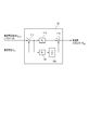
- FIG. 1 is a diagram schematically illustrating a configuration example of a vehicle system according to an embodiment.
- FIG. 2 is a diagram for explaining a configuration example of the first power transmission mechanism of the vehicle system shown in FIG. 1.
- FIG. 3 is a block diagram schematically showing a configuration example of the vehicle control device shown in FIG. 4 is a block diagram schematically showing a configuration example of the DC voltage constant control unit shown in FIG.
- FIG. 5 is a block diagram schematically illustrating a configuration example of the vehicle control device of the vehicle system of the second embodiment.
- FIG. 6 is a block diagram schematically showing the configuration of the vehicle control device of the vehicle system of the third embodiment.
- FIG. 7 is a block diagram schematically showing another configuration example of the vehicle control device of the vehicle system of the third embodiment.
- the vehicle system of this embodiment includes an internal combustion engine 10, a first power transmission mechanism 20, a generator (first electric motor) 30, a first inverter 40, a second inverter 50, and a motor (second electric motor) 60.
- the internal combustion engine 10 is a prime mover that generates mechanical energy for driving a vehicle, such as a gasoline engine or a diesel engine.
- the first power transmission mechanism 20 is configured to transmit the rotational motion of the internal combustion engine 10 to the generator side 30 and the wheel WL side (axle 80 side), and the mechanical energy generated by the internal combustion engine 10 is transmitted to the generator.
- This is a three-axis power transmission mechanism that distributes energy supplied to the 30 side and energy supplied to the wheel WL side (axle 80 side).
- FIG. 2 is a diagram for explaining a configuration example of the first power transmission mechanism of the vehicle system shown in FIG. 1.
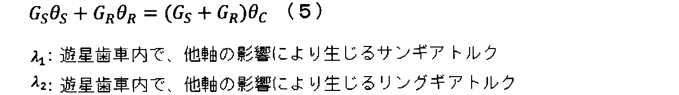
- the first power transmission mechanism 20 is, for example, a planetary gear, and rotates along the orbit of the sun gear S, the planetary gear P circumscribing the sun gear S, the ring gear R inscribed by the planetary gear P, and the planetary gear P.
- planetary carrier C In the present embodiment, the planetary carrier C is rotated by mechanical energy Pe generated by the internal combustion engine 10.
- the rotational power of the sun gear S is transmitted to the generator 30.
- the rotational power of the ring gear R is transmitted to the second power transmission mechanism 70 connected to the axle 80.
- ⁇ is the rotation angle of the gear, electric motor, etc.
- ⁇ is the rotation angular velocity of the gear, electric motor, etc.
- T is the torque of the gear, electric motor, etc.
- J is the inertia of the gear, electric motor, etc.
- G is the number of gear teeth.
- S is related to the sun gear
- P is related to the planetary gear
- C is related to the planetary carrier
- R is related to the ring gear.
- the generator 30 converts mechanical energy Pg supplied via the sun gear S of the first power transmission mechanism 20 into electrical energy.
- the generator 30 is an electric motor including, for example, a rotor that is linked to the sun gear S and a stator, and outputs three-phase AC power.
- the first inverter 40 is a control means for controlling the operation of the generator 30 and converts the three-phase AC power output from the generator 30 into DC power for regenerative operation and is supplied from the DC link.
- the DC power is converted into three-phase AC power and supplied to the generator 30, and the generator 30 is set to a power running operation.
- the first inverter 40 is connected to the second inverter 50 and the battery BT via a DC link.
- a capacitor is connected to the DC side of the first inverter 40.
- the second inverter 50 converts the DC power supplied from the DC link into AC power and outputs the AC power to the motor 60.
- the second inverter 50 converts AC power supplied from the motor 60 into DC power and outputs the DC power to the DC link.
- a capacitor is connected to the DC side of the second inverter 50.
- the voltage detector VS detects the voltage of the DC link.
- the DC voltage (inter-link voltage) VDC detected by the voltage detector VS is supplied to the vehicle control device CTR.
- the motor 60 is an electric motor driven by AC power supplied from the second inverter 50, and converts electric energy into mechanical energy Pm and outputs it to the second power transmission mechanism 70.
- the second power transmission mechanism 70 can transmit rotational motion between the second inverter 50 and the axle 80 and between the first power transmission mechanism 20 and the axle 80. That is, the second power transmission mechanism 70 can transmit the energy Pout obtained by combining the mechanical energy transmitted from the internal combustion engine 10 via the ring gear R and the mechanical energy supplied from the second inverter 50 to the axle 80. is there. Further, the rotational movement of the axle 80 can be transmitted to the ring gear R and the second inverter 50. The wheel WL is rotationally driven via the axle 80.
- the battery BT includes, for example, a storage battery including a plurality of secondary battery cells, can be charged by power supplied from the DC link, and can be discharged to the DC link.
- the auxiliary machine 90 is a load mounted in the vehicle such as a lighting device.
- the auxiliary machine 90 is connected to the battery BT, the first inverter 40, and the second inverter 50 through a DC link, and is driven by energy supplied from the DC link.
- the vehicle control device CTR is a control unit that controls the internal combustion engine 10, the generator 30, the first inverter 40, the second inverter 50, the motor 60, and the battery BT to operate in conjunction with each other.
- the vehicle control device CTR is a computing means including a processor such as a CPU (central processing unit) or MPU (micro processing unit) and a memory, for example.
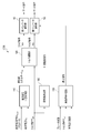
- FIG. 3 is a block diagram schematically showing a configuration example of the vehicle control apparatus CTR shown in FIG.
- the subscript “E” is attached to the value related to the internal combustion engine 10
- the subscript “MG1” is attached to the value related to the generator 30, and the subscript “MG2” is assigned to the motor A value related to 60 is attached.
- the vehicle control device CTR includes a rotation speed determination unit 100, a DC voltage constant control unit 110, a torque calculation unit 120, a first inverter control unit 42, and a second inverter control unit 52.
- the rotation speed determination unit 100 includes, for example, a table that stores the rotation speed of the internal combustion engine 10 corresponding to the output torque of the axle 80.
- the rotational speed determination unit 100 receives an axle output torque command (axle torque command) Tref supplied from the outside, reads out the rotational speed of the internal combustion engine 10 corresponding to the axle torque command Tref from the table, and outputs it.
- the DC voltage constant control unit 110 receives the DC voltage command (interlink voltage command) V DCref and the DC voltage V DC , and the difference between the value of the link voltage command V DCref and the value of the DC voltage V DC is zero. so as to calculates and outputs the value of the DC unit energy P DC.
- the DC voltage constant control unit 110 includes a subtractor 112, a proportional gain multiplier 114, an integral gain multiplier 116, an integrator 118, and an adder 119.
- the subtractor 112 receives the link voltage command V DCref and the DC voltage V DC, and the difference obtained by subtracting the value of the DC voltage V DC from the value of the link voltage command V DCref is the proportional constant multiplier 114 and the integral gain. To the multiplier 116.
- the proportional gain multiplier 114 multiplies the input difference value (V DCref ⁇ V DC ) by the proportional gain Kp and outputs the result to the adder 119.
- the integral gain multiplier 116 multiplies the input difference value (V DCref ⁇ V DC ) by the integral gain KI and outputs the result to the integrator 118.
- the integrator 118 integrates the value (KI ⁇ (V DCref ⁇ V DC )) input from the integration gain multiplier 116 and outputs the result to the adder 119.
- the adder 119 adds the value (Kp ⁇ (V DCref ⁇ V DC )) input from the proportional gain multiplier 114 and the value (KI ⁇ (V DCref ⁇ V DC ) / s) input from the integrator. And output as direct current energy P DC .
- Torque computing section 120 receives a DC section energy P DC and axle torque command Tref, the output torque of the axle 80 can be regarded as the axle torque command Tref, and, as the voltage of the DC link is constant, power It calculates a torque command T MG2 torque command T MG1 and the motor 60 of the machine 30.
- the torque commands T MG1 and T MG2 calculated by the torque calculation unit 120 will be described. Since the generator 30 is connected to the sun gear S of the first power transmission mechanism 20, the torque Ts generated in the sun gear S is equal to the torque T MG1 generated in the generator 30 (formula (9)). In consideration of this, the following equation (10) is obtained from the relationship between the above equations (6) and (7).
- the output torque T OUT of the axle and the direct current energy P DC can be determined independently. Therefore, the direct current energy P DC is energy consumed by the accessory 90. By setting in this way, it is possible to change the axle torque T OUT to an arbitrary value while keeping the DC link voltage constant.
- the amount of energy consumed by the auxiliary machine 90 is indefinite, and even if the energy consumed by the auxiliary machine 90 can be detected, it is difficult to control with high accuracy due to the influence of detection errors and the like. . Therefore, in this embodiment, by using the values calculated by the DC voltage constant control unit 110 as a DC unit energy P DC, it has a DC link voltage constant.
- a first arithmetic term has a negative value obtained by dividing the sum of the product of the rotational angular velocity omega R the number of teeth G R and the ring gear R of the product and the ring gear R of the DC and the number of teeth G S of the sun gear S the product of part energy P DC, the product of the rotational angular velocity omega R the number of teeth G R and the ring gear R of the product and the ring gear R of the rotational angular velocity omega S of teeth G S and the sun gear S of the sun gear S
- This is a value obtained by adding the second arithmetic term in which the value divided by the sum is negative.
- Torque command T MG2 motor 60 the product of the rotational angular velocity omega S and the axle torque command T OUT of the number of teeth G S and the sun gear S of the sun gear S, the rotation angular velocity of the teeth G S and the sun gear S of the sun gear S omega S third arithmetic section and the number of teeth G S of the sun gear S and the DC unit energy P DC divided by the sum of the product of the rotational angular velocity omega R the number of teeth G R and the ring gear R of the product and the ring gear R of the Divided by the sum of the product of the number of teeth G S of the sun gear S and the rotational angular velocity ⁇ S of the sun gear S and the product of the number of teeth ⁇ R of the ring gear R and the rotational angular velocity ⁇ R of the ring gear R.
- the first inverter control unit 42 receives the torque command T MG1 from the torque calculation unit 120, performs control (such as vector control) for outputting the torque of the torque command T MG1 , and issues a gate command to the first inverter 40. Generate and output.
- the second inverter control unit 52 receives the torque command T MG2 from the torque calculation unit 120, performs control (vector control or the like) for outputting the torque of the torque command T MG2 , and issues a gate command to the second inverter 50. Generate and output.
- the DC link voltage is kept constant even when the battery BT is not connected to the DC link, and any The output torque T OUT that realizes the axle torque command Tref set to can be output from the axle 80. That is, according to the vehicle system of the present embodiment, stable driving can be realized.
- FIG. 5 is a block diagram schematically illustrating a configuration example of the vehicle control device of the vehicle system of the second embodiment.
- the vehicle control device CTR includes a plurality of processors, and the generator control unit MC2 that controls the generator 30, the motor control unit MC3 that controls the motor 60, and the overall control unit MC1 are different processors. Operate.
- the overall control unit MC1 is configured to be able to communicate with both the generator control unit MC2 and the motor control unit MC3.
- the generator control unit MC2 and the motor control unit MC3 cannot communicate with each other.
- the generator control unit MC2 and the motor control unit MC3 can communicate with each other via communication means (not shown) of the overall control unit MC1.
- a configuration in which the generator 30 and the motor 60 are controlled in cooperation using a plurality of processors as described above will be described.
- the vehicle control device CTR is the generator rotational angular velocity omega MG1 and the motor (first motor) 30 on the basis of the rotational angular velocity omega MG2 (second electric motor) 60, an electric motor controls the voltage of the DC link
- the DC link voltage is controlled by the operation of the motor 60
- the first control signal CMD1 is 1
- the second control signal CMD2 is 0 (second level different from the first level).
- the first control signal CMD1 becomes 0 (second level)
- the second control signal CMD2 becomes 1.
- the voltage of the DC link is controlled to be constant based on the output signal of one of the first DC voltage constant controller 110A and the second DC voltage constant controller 110B.
- the 1 control signal CMD1 and the second control signal CMD2 become 1 exclusively.
- control is performed to increase the DC link voltage due to an error in a sensor or a circuit.
- a control unit that performs control and a control unit that controls to lower the voltage of the DC link occurs, and the operations of the first DC voltage constant control unit 110A and the second DC voltage constant control unit 110B may fail.
- the constant DC voltage controller 110 includes a first constant DC voltage controller (first controller) 110A, a second constant DC voltage controller (second controller) 110B, a first switch SWA, and a second switch. SWB.
- the output DC1 of the first DC voltage constant control unit 110A is, for example, zero.
- the output P DC2 of the second DC voltage constant control unit 110B is not used in any configuration, so that the operation of other configurations can be performed regardless of the value of the output P DC2. It does not affect and may be set to a value other than zero.
- the output P DC1 of the first DC voltage constant control unit 110A is input to the first input terminal, and the output P DC2 of the second DC voltage constant control unit 110B is input to the second input terminal.
- the output P DC2 of the second DC voltage constant control unit 110B is input to the third input terminal, and the output P DC1 of the first DC voltage constant control unit 110A is input to the fourth input terminal.
- the torque calculation unit 120 includes a partial torque calculation unit 120 ′, a first calculation unit 140A, a first adder 150A, a second calculation unit 140B, and a second adder 150B.
- the partial torque calculation unit 120 ′ receives the axle torque command Tref, and a term (first calculation term) relating to the axle torque command Tref in the above equation (19) and a term relating to the axle torque command Tref in the above equation (20). (Third operation term) is calculated.
- First operation unit 140A receives the value output from the first switch SWA, computes the term (second operand) regarding the DC unit energy P DC of the aforementioned formula (19).
- the first adder 150A adds the first calculation term and the second calculation term and outputs the result.
- the second calculation unit 140B receives the value output from the second switch SWB, and calculates a term (fourth calculation term) related to the direct current energy P DC in the above-described equation (20).
- the second adder 150B adds the third calculation term and the fourth calculation term and outputs the result.
- the vehicle control device CTR includes an overall control unit MC1, a generator control unit MC2, and a motor control unit MC3.
- the overall control unit MC1, the generator control unit MC2, and the motor control unit MC3 are configured to operate by different processors.
- the overall control unit MC1 includes a rotation speed determination unit 100, a partial torque calculation unit 120 ′, and a DC voltage constant control selection unit 130.
- the rotational speed determination unit 100 includes a table that stores the rotational speed of the internal combustion engine 10 corresponding to the output torque of the axle 80, for example, as in the first embodiment.
- the rotational speed determination unit 100 receives an axle torque command Tref supplied from the outside, reads out the rotational speed of the internal combustion engine 10 corresponding to the axle torque command Tref from the table, and outputs it.
- the partial torque calculation unit 120 ′ receives the axle torque command Tref supplied from the outside, and a term related to the axle torque command Tref of the torque commands T MG1 and T MG2 calculated by the above formulas (19) and (20) ( The following partial torque commands T MG1 ′ and T MG2 ′ corresponding to the above-described first calculation term and third calculation term) are calculated and output.
- the DC voltage constant control selection unit 130 includes the rotational angular speed ⁇ MG1 of the generator 30, the maximum torque characteristic T MAX-MG1 of the generator 30, the rotational angular speed ⁇ MG2 of the motor 60, and the maximum torque characteristic T MAX- of the motor 60.
- MG2 is received and a first control signal CMD1 and a second control signal CMD2 are output.
- the first control signal CMD1 and the second control signal CMD2 are signals for selecting whether the generator 30 controls the DC link voltage to be constant or the motor 60 controls the DC link voltage to be constant. .
- the DC link is connected between the first inverter 40 that drives the generator 30 that is the first electric motor and the second inverter 50 that drives the motor 60 that is the second electric motor.
- the constant voltage control can be performed by either the operation of the generator 30 or the operation of the motor 60.
- An electric motor generally has a limit in the torque that can be output. If the maximum torque T MAX that can be output when the motor is rotating at the angular velocity ⁇ is set, the motor having a larger product of the angular velocity ⁇ and the maximum torque T MAX has more reserve power for DC link voltage control. Will be. From the above, the constant DC voltage control selection unit 130 calculates the product of the rotational angular speed ⁇ MG1 of the generator 30 and the maximum torque T MAX-MG1, and the rotational angular speed ⁇ MG2 and the maximum torque T MAX-MG2 of the motor 60. The first control signal CMD1 and the second control signal CMD2 are output so as to perform voltage control of the DC link using the motor having the larger product of the rotational angular velocity and the maximum torque.
- the first control signal CMD1 is “1” and the second control signal CMD2 is “0”.
- the first control signal CMD1 is “0” and the second control signal CMD2 is “1”.
- the first control signal CMD1 and the second control signal CMD2 indicate, for example, a voltage control stop request when the value is “0” and a voltage control operation request when the value is “1”.
- the generator control unit MC2 includes a first DC voltage constant control unit 110A, a first calculation unit 140A, a first adder 150A, a first inverter control unit 42, and a first switch SWA. .
- the first DC voltage constant control unit 110A receives the first control signal CMD1, the DC link voltage target value V DCref and the DC voltage detection value V DC, and the value of the first control signal CMD1 is “1”. Sometimes, as in the DC voltage constant control unit 110 of the first embodiment, the value of the DC unit energy P DC1 is calculated so that the difference between the link voltage command V DCref and the DC voltage detection value V DC becomes zero. And output. The direct current energy PDC1 is supplied to one of the input terminals of the switch SWA and the other input terminal of the switch SWB described later via the overall control unit MC1.
- the first switch SWA has two input terminals (first input terminal and second input terminal) and one output terminal, and the first input terminal and the second input according to the value of the first control signal CMD1. Switch so that one of the terminals is electrically connected to the output terminal.
- the switch SWA electrically connects the first input terminal and the output terminal when the value of the first control signal CMD1 is “1”, and the second input terminal when the value of the control signal CMD1 is “0”. Are electrically connected to the output terminal.
- First operation unit 140A receives one of the DC portion energy P DC2 to the DC unit energy P DC1 from switch SWA, the above equation (19), a DC torque command TMG1 that is calculated by (20) The following constant voltage command AVR1 corresponding to a term related to the partial energy PDC (the second calculation term) is output to the first adder 150A.
- the first adder 150A receives the partial torque command T MG1 ′ output from the partial torque calculation unit 120 ′ of the overall control unit MC1 and the constant voltage command AVR1 output from the first calculation unit 140A, and receives the partial torque.
- a value obtained by adding the command T MG1 ′ and the constant voltage command AVR 1 is output to the first inverter control unit 42 as the torque command T MG1 of the generator 30.
- the first inverter control unit 42 similarly to the first embodiment described above, receives the torque command T MG1, and controls (such as vector control) for outputting the torque of the torque command T MG1, first inverter 40 Generate and output a gate command to.
- the motor control unit MC3 includes a second DC voltage constant control unit 110B, a second calculation unit 140B, a second adder 150B, a second inverter control unit 52, and a second switch SWB.
- the second DC voltage constant control unit 110B receives the second control signal CMD2, the DC link voltage target value V DCref and the DC voltage detection value V DC, and the value of the second control signal CMD2 is “1”.
- the value of the DC unit energy P DC2 is calculated so that the difference between the link voltage command V DCref and the DC voltage detection value V DC becomes zero.
- the direct current unit energy PDC2 is supplied to the third input terminal of the second switch SWB and the second input terminal of the switch SWA described above via the overall control unit MC1.
- the second switch SWB has two input terminals (a third input terminal and a fourth input terminal) and one output terminal, and the third input terminal and the fourth input according to the value of the second control signal CMD2. Switch so that one of the terminals is electrically connected to the output terminal.
- the second switch SWB electrically connects the third input terminal and the output terminal when the value of the second control signal CMD2 is “1”, and when the value of the second control signal CMD2 is “0”.
- the fourth input terminal and the output terminal are electrically connected.
- the second calculation unit 140B receives either one of the direct current energy P DC2 and the direct current energy P DC1 from the second switch SWB, and calculates the torque command T calculated by the above equations (19) and (20).
- the following constant voltage command AVR2 corresponding to the term relating to the DC part energy PDC of MG2 (the fourth arithmetic term) is output to adder 150B.
- the second adder 150B receives the partial torque command T MG2 ′ output from the partial torque calculation unit 120 ′ of the overall control unit MC1 and the constant voltage command AVR2 output from the second calculation unit 140B.
- a value obtained by adding the command T MG2 ′ and the constant voltage command AVR 2 is output to the second inverter control unit 52 as the torque command TMG 2 of the motor 60.
- the second inverter control unit 52 similarly to the first embodiment described above, receives the torque command T MG2, and controls (such as vector control) for outputting the torque of the torque command T MG2, the second inverter 50 Generate and output a gate command to.
- the torque commands T MG1 and T MG2 can be expressed as follows.
- the torque commands T MG1 and T MG2 can be expressed as follows.
- the DC link constant voltage control is performed by the operation of the generator 30 when the generator 30 is rotating at a constant speed
- the generator 30 is rotating at a low speed when the energy consumption of the auxiliary machine 90 changes. Therefore, large energy cannot be generated, and there is a possibility that it cannot follow the energy consumption change of the accessory 90.
- the motor 60 may immediately follow the change in energy consumption of the auxiliary device due to a communication delay between the control unit of the generator 30 and the control unit of the motor 60, and the value of the DC unit energy is not sent immediately. It may not be possible. In these cases, since the voltage of the DC link varies, the operation of the entire vehicle system may stop.
- the operation of the generator of either the generator 30 or the motor 60 depends on the operation of the DC link. Since it is determined whether to perform voltage control, stable DC link voltage control can be realized.
- the control unit of the electric motor is not performed a voltage control by receiving the DC link energy P DC from the control unit of the motor is performing a voltage control, it can follow even when the voltage of the DC link has changed It becomes possible.
- even if a communication delay occurs when the configuration for controlling the generator 30 and the configuration for controlling the motor 60 are operated by different processors it is about 10 ms to 100 ms. That is, according to the vehicle system of the present embodiment, stable driving can be realized.
- the DC voltage constant control selection unit 130 performs voltage control on the motor having the larger value of the product of the rotational angular velocity and the maximum torque, but only the rotational angular velocity is compared, You may select as an electric motor with a larger rotational angular velocity performing voltage control. Even in that case, the same effects as those of the second embodiment described above can be obtained.
- the present embodiment can be applied even to a vehicle that does not include a rotational angular velocity sensor.
- the vehicle system of the present embodiment has a configuration that takes into account the operation when the vehicle is stopped, that is, when the generator 30 is stopped.
- FIG. 6 is a block diagram schematically showing the configuration of the vehicle control device of the vehicle system of the third embodiment.
- the control device CTR is configured to further include a vehicle stop determination unit 150 in the control device CTR in the vehicle system of the first embodiment.
- Vehicle stop determination unit 150 receives a brake state supplied from the outside, and the axle torque command Tref, and the vehicle traveling speed omega R, and outputs a stop command to the second inverter control unit 52.
- the vehicle stop determination unit 150 is in a state where the brake is applied, and when the value of the axle torque command Tref is “0” and the vehicle traveling speed is “0”, the vehicle is stopped.
- the stop command is set to “1”, and the stop command is set to “0” when the above condition is not satisfied.
- the rotational angular velocity ⁇ MG2 of the motor is 0 when the vehicle is stopped. Therefore, when the vehicle is stopped, the motor 60 does not supply energy to the DC link, so the motor 60 does not affect the voltage control of the DC link. Furthermore, when the vehicle brake mechanism (not shown) is operating, the brake mechanism bears the torque generated by the motor 60 instead. Therefore, when the vehicle is stopped, the second inverter 50 may stop operating, and by not performing unnecessary operations, the failure rate can be reduced and the electric power of the motor 60 and the second inverter 50 can be reduced. Temperature rise due to dynamic energy loss can be suppressed. That is, according to the vehicle system of the present embodiment, stable driving can be realized.
- the torque commands T MG1 and T MG2 are as follows.
- FIG. 7 is a block diagram schematically showing another configuration example of the vehicle control device of the vehicle system of the third embodiment.
- the vehicle control device CTR is configured to further include a vehicle stop determination unit 150 in the vehicle control device in the vehicle system of the second embodiment.
- the vehicle stop determination unit 150 receives the brake state supplied from the outside, the torque command Tref, and the vehicle travel speed ⁇ R, and outputs a stop command to the second inverter control unit 52.
- the vehicle stop determination unit 150 is in a state where the brake is applied, and when the value of the axle torque command Tref is “0” and the vehicle traveling speed is “0”, the vehicle is stopped.
- the stop command is set to “1”, and the stop command is set to “0” when the above condition is not satisfied.
Abstract
A vehicle system according to an embodiment of the present invention realizes stabilized drive, the vehicle system being provided with: an internal combustion engine (10); a first motor (30); a first power transmission mechanism (20) for transmitting the rotation operation of the internal combustion engine (10) to the first motor (30) and a second power transmission mechanism (70); a second motor (60) connected to the second power transmission mechanism (70); a first inverter (40) for driving the first motor (30); a second inverter (50) for driving the second motor (60) and connected to the first inverter via a DC link; an axle (80) that is linked to the second power transmission mechanism (70) and rotates; a voltage detector VS for detecting the DC voltage of the DC link; a DC voltage constant-control unit (110) for outputting DC unit energy so that an interlink voltage command and the DC voltage supplied from the voltage detector VS are equal; and a torque calculation unit (120) for calculating torque commands for the first motor (30) and the second motor (60) so that the output torque of the axle (80) is equal to the axle torque command, and the voltage of the DC link is constant.
Description
本発明の実施形態は、車両システムに関する。
Embodiments of the present invention relate to a vehicle system.
内燃機関から供給されるエネルギーと、蓄電池から供給されるエネルギーとの両方を車軸に伝達可能に構成されたハイブリッド車両システムが提案されている。
A hybrid vehicle system has been proposed in which both energy supplied from an internal combustion engine and energy supplied from a storage battery can be transmitted to an axle.
シリーズパラレルハイブリッド車両システムは、内燃機関から供給されるエネルギーを発電機側と車軸側とに伝達する三軸動力伝達機構を有している。シリーズパラレルハイブリッド車両システムでは、車軸は、内燃機関から三軸動力伝達機構を介して車軸に供給されるエネルギーと、発電機から供給される電気エネルギーと蓄電池から供給されるエネルギーとを用いて回転する。
The series parallel hybrid vehicle system has a three-axis power transmission mechanism that transmits energy supplied from the internal combustion engine to the generator side and the axle side. In the series parallel hybrid vehicle system, the axle rotates using energy supplied from the internal combustion engine to the axle via a three-axis power transmission mechanism, electric energy supplied from the generator, and energy supplied from the storage battery. .
また、シリーズパラレルハイブリッド車両システムでは、車軸(車速)と内燃機関の回転速度を独立に決定することが可能である。また、シリーズパラレルハイブリッド車両システムでは、車両の出力トルクと内燃機関の出力とを独立に決定することが可能である。これにより、車両の運転状態によらず、内燃機関の動作点を決めることができるので、内燃機関の動作点として効率が良い点に選ぶことで、内燃機関の高効率運転が可能となり、燃費を向上することができる。
In the series parallel hybrid vehicle system, the axle (vehicle speed) and the rotational speed of the internal combustion engine can be determined independently. In the series parallel hybrid vehicle system, the output torque of the vehicle and the output of the internal combustion engine can be determined independently. As a result, the operating point of the internal combustion engine can be determined regardless of the driving state of the vehicle. Therefore, by selecting the operating point of the internal combustion engine as a high-efficiency point, the internal combustion engine can be operated efficiently and the fuel efficiency can be improved. Can be improved.
また、内燃機関の出力エネルギーと、車両の出力エネルギーとに差がある場合には、直流リンクに接続された蓄電池の充放電により、エネルギーの過不足を調整することも可能である。
Also, if there is a difference between the output energy of the internal combustion engine and the output energy of the vehicle, it is possible to adjust the excess or deficiency of energy by charging / discharging the storage battery connected to the DC link.
シリーズパラレルハイブリッド車両システムは、例えば、発電機を駆動するインバータと、モータを駆動するインバータと、2つのインバータの間を接続する直流リンクと、直流リンクに接続した蓄電池と、直流リンクから給電される補機と、を備えている。
The series parallel hybrid vehicle system is powered by, for example, an inverter that drives a generator, an inverter that drives a motor, a DC link that connects the two inverters, a storage battery that is connected to the DC link, and a DC link. An auxiliary machine.
バッテリに不具合が発生したとき等に直流リンクとバッテリとを電気的に切り離すと、補機で消費されるエネルギーの変化により直流リンクの電圧が変化し、インバータを安定して駆動することが難しかった。更に、インバータの動作が不安定になると、車両システム全体が停止することがあった。
また、バッテリが劣化することを回避するために、バッテリを直流リンクから切り離した状態でも、安定した動作が可能な車両システムが望まれていた。 When the DC link and the battery are electrically disconnected when a failure occurs in the battery, the voltage of the DC link changes due to the change in energy consumed by the auxiliary equipment, making it difficult to drive the inverter stably. . Furthermore, when the operation of the inverter becomes unstable, the entire vehicle system may stop.
In order to avoid the deterioration of the battery, a vehicle system capable of stable operation even when the battery is disconnected from the DC link has been desired.
本発明の実施形態は、上記事情を鑑みて成されたものであって、安定した駆動を実現する車両システムを提供することを目的とする。
Embodiments of the present invention have been made in view of the above circumstances, and an object thereof is to provide a vehicle system that realizes stable driving.
実施形態による車両システムは、内燃機関と、第1電動機と、第2電動機と、前記内燃機関の回転運動を、前記第1電動機と第2動力伝達機構とに伝達する第1動力伝達機構と、前記第2動力伝達機構と連結され回転する車軸と、前記第2動力伝達機構は、前記第2電動機と前記車軸との間、および、前記第1動力伝達機構と前記車軸との間で回転運動を伝達し、前記第1電動機を駆動する第1インバータと、直流リンクを介して前記第1インバータと接続し、前記第2電動機を駆動する第2インバータと、前記直流リンクのリンク間電圧を検出する電圧検出器と、外部から供給されるリンク間電圧指令と、前記リンク間電圧とが等しくなるように、直流部エネルギーを出力する直流電圧一定制御部と、外部から供給される車軸トルク指令と、前記直流部エネルギーとを受信し、前記車軸の出力トルクが前記車軸トルク指令と等しく、かつ、前記直流リンクの電圧が一定となるように、前記第1電動機のトルク指令と、前記第2電動機のトルク指令とを演算するトルク演算部と、前記第1電動機のトルク指令に基づいて前記第1インバータへゲート指令を出力する第1インバータ制御部と、前記第2電動機のトルク指令に基づいて前記第2インバータへゲート指令を出力する第2インバータ制御部と、を備える。
A vehicle system according to an embodiment includes an internal combustion engine, a first electric motor, a second electric motor, and a first power transmission mechanism that transmits rotational motion of the internal combustion engine to the first electric motor and a second power transmission mechanism. The axle connected to the second power transmission mechanism and rotating, the second power transmission mechanism rotating between the second electric motor and the axle, and between the first power transmission mechanism and the axle. The first inverter that drives the first motor and the first inverter connected to the first inverter via a DC link, and detects the voltage between the links of the DC link and the second inverter that drives the second motor. A voltage detector, a link voltage command supplied from outside, and a DC voltage constant control unit that outputs DC energy so that the link voltage is equal, and an axle torque command supplied from outside , Receiving the direct current energy, the torque command of the first motor and the second motor so that the output torque of the axle is equal to the axle torque command and the voltage of the DC link is constant. A torque calculation unit that calculates a torque command of the first motor, a first inverter control unit that outputs a gate command to the first inverter based on the torque command of the first motor, and a torque command of the second motor A second inverter control unit that outputs a gate command to the second inverter.
以下、実施形態の車両システムについて、図面を参照して説明する。
本実施形態の車両システムは、内燃機関10と、第1動力伝達機構20と、発電機(第1電動機)30と、第1インバータ40と、第2インバータ50と、モータ(第2電動機)60と、第2動力伝達機構70と、車軸80と、補機90と、車輪WLと、車両制御装置CTRと、電圧検出器VSと、を備えている。 Hereinafter, a vehicle system according to an embodiment will be described with reference to the drawings.
The vehicle system of this embodiment includes aninternal combustion engine 10, a first power transmission mechanism 20, a generator (first electric motor) 30, a first inverter 40, a second inverter 50, and a motor (second electric motor) 60. A second power transmission mechanism 70, an axle 80, an auxiliary machine 90, wheels WL, a vehicle control device CTR, and a voltage detector VS.
本実施形態の車両システムは、内燃機関10と、第1動力伝達機構20と、発電機(第1電動機)30と、第1インバータ40と、第2インバータ50と、モータ(第2電動機)60と、第2動力伝達機構70と、車軸80と、補機90と、車輪WLと、車両制御装置CTRと、電圧検出器VSと、を備えている。 Hereinafter, a vehicle system according to an embodiment will be described with reference to the drawings.
The vehicle system of this embodiment includes an
内燃機関10は、ガソリンエンジンやディーゼルエンジン等、車両を駆動する機械エネルギーを生成する原動機である。
第1動力伝達機構20は、内燃機関10の回転運動を発電機側30と車輪WL側(車軸80側)とに伝達する構成であって、内燃機関10で生成された機械エネルギーを、発電機30側に供給されるエネルギーと、車輪WL側(車軸80側)に供給されるエネルギーとに分配する三軸動力伝達機構である。 Theinternal combustion engine 10 is a prime mover that generates mechanical energy for driving a vehicle, such as a gasoline engine or a diesel engine.
The firstpower transmission mechanism 20 is configured to transmit the rotational motion of the internal combustion engine 10 to the generator side 30 and the wheel WL side (axle 80 side), and the mechanical energy generated by the internal combustion engine 10 is transmitted to the generator. This is a three-axis power transmission mechanism that distributes energy supplied to the 30 side and energy supplied to the wheel WL side (axle 80 side).
第1動力伝達機構20は、内燃機関10の回転運動を発電機側30と車輪WL側(車軸80側)とに伝達する構成であって、内燃機関10で生成された機械エネルギーを、発電機30側に供給されるエネルギーと、車輪WL側(車軸80側)に供給されるエネルギーとに分配する三軸動力伝達機構である。 The
The first
図2は、図1に示す車両システムの第1動力伝達機構の一構成例を説明するための図である。
第1動力伝達機構20は、例えば遊星歯車であって、サンギアSと、サンギアSに外接したプラネタリアギアPと、プラネタリアギアPが内接したリングギアRと、プラネタリアギアPの軌道に沿って回転するプラネタリキャリアCと、を備えている。本実施形態では、プラネタリキャリアCは、内燃機関10で生成された機械エネルギーPeにより回転する。サンギアSの回転動力は発電機30へ伝達される。リングギアRの回転動力は車軸80と接続した第2動力伝達機構70に伝達される。 FIG. 2 is a diagram for explaining a configuration example of the first power transmission mechanism of the vehicle system shown in FIG. 1.
The firstpower transmission mechanism 20 is, for example, a planetary gear, and rotates along the orbit of the sun gear S, the planetary gear P circumscribing the sun gear S, the ring gear R inscribed by the planetary gear P, and the planetary gear P. And planetary carrier C. In the present embodiment, the planetary carrier C is rotated by mechanical energy Pe generated by the internal combustion engine 10. The rotational power of the sun gear S is transmitted to the generator 30. The rotational power of the ring gear R is transmitted to the second power transmission mechanism 70 connected to the axle 80.
第1動力伝達機構20は、例えば遊星歯車であって、サンギアSと、サンギアSに外接したプラネタリアギアPと、プラネタリアギアPが内接したリングギアRと、プラネタリアギアPの軌道に沿って回転するプラネタリキャリアCと、を備えている。本実施形態では、プラネタリキャリアCは、内燃機関10で生成された機械エネルギーPeにより回転する。サンギアSの回転動力は発電機30へ伝達される。リングギアRの回転動力は車軸80と接続した第2動力伝達機構70に伝達される。 FIG. 2 is a diagram for explaining a configuration example of the first power transmission mechanism of the vehicle system shown in FIG. 1.
The first
第1動力伝達機構20の、サンギアS、リングギアR、プラネタリアギアP、および、プラネタリアキャリアCの運動方程式を以下に示す。
なお、θはギア、電動機等の回転角度、ωはギア、電動機等の回転角速度、Tはギア、電動機等のトルク、Jはギア、電動機等のイナーシャ、Gはギア歯数である。また、上記記号の添え字は、Sはサンギアに関するもの、Pはプラネタリギアに関するもの、Cはプラネタリキャリアに関するもの、Rはリングギアに関するものを表している。 The equation of motion of the sun gear S, the ring gear R, the planetary gear P, and the planetary carrier C of the firstpower transmission mechanism 20 is shown below.
Here, θ is the rotation angle of the gear, electric motor, etc., ω is the rotation angular velocity of the gear, electric motor, etc., T is the torque of the gear, electric motor, etc., J is the inertia of the gear, electric motor, etc., G is the number of gear teeth. In addition, the subscripts of the above symbols indicate that S is related to the sun gear, P is related to the planetary gear, C is related to the planetary carrier, and R is related to the ring gear.
なお、θはギア、電動機等の回転角度、ωはギア、電動機等の回転角速度、Tはギア、電動機等のトルク、Jはギア、電動機等のイナーシャ、Gはギア歯数である。また、上記記号の添え字は、Sはサンギアに関するもの、Pはプラネタリギアに関するもの、Cはプラネタリキャリアに関するもの、Rはリングギアに関するものを表している。 The equation of motion of the sun gear S, the ring gear R, the planetary gear P, and the planetary carrier C of the first
Here, θ is the rotation angle of the gear, electric motor, etc., ω is the rotation angular velocity of the gear, electric motor, etc., T is the torque of the gear, electric motor, etc., J is the inertia of the gear, electric motor, etc., G is the number of gear teeth. In addition, the subscripts of the above symbols indicate that S is related to the sun gear, P is related to the planetary gear, C is related to the planetary carrier, and R is related to the ring gear.

なお、上記運動方程式における拘束条件は下記のようになる。
The constraint conditions in the equation of motion are as follows.
ここで、サンギアSと、内燃機関10と、プラネタリギアPとのイナーシャが、車両の慣性質量に対して無視できる程度に小さいとすると、運動方程式を下記のように記載することができる。

Here, if the inertia of the sun gear S, the internal combustion engine 10, and the planetary gear P is small enough to be ignored with respect to the inertial mass of the vehicle, the equation of motion can be described as follows.
発電機30は、第1動力伝達機構20のサンギアSを介して供給される機械エネルギーPgを電気エネルギーに変換する。発電機30は、例えば、サンギアSと連動する回転子と、固定子とを備えた電動機であって、3相交流電力を出力する。
The generator 30 converts mechanical energy Pg supplied via the sun gear S of the first power transmission mechanism 20 into electrical energy. The generator 30 is an electric motor including, for example, a rotor that is linked to the sun gear S and a stator, and outputs three-phase AC power.
第1インバータ40は、発電機30の動作を制御する制御手段であって、発電機30から出力された3相交流電力を直流電力に変換して回生動作とするとともに、直流リンクから供給される直流電力を3相交流電力に変換して発電機30へ供給し、発電機30を力行動作とする。第1インバータ40は直流リンクを介して第2インバータ50およびバッテリBTと接続している。第1インバータ40の直流側にはコンデンサが接続している。
The first inverter 40 is a control means for controlling the operation of the generator 30 and converts the three-phase AC power output from the generator 30 into DC power for regenerative operation and is supplied from the DC link. The DC power is converted into three-phase AC power and supplied to the generator 30, and the generator 30 is set to a power running operation. The first inverter 40 is connected to the second inverter 50 and the battery BT via a DC link. A capacitor is connected to the DC side of the first inverter 40.
第2インバータ50は、直流リンクから供給された直流電力を交流電力に変換してモータ60へ出力する。また、第2インバータ50は、モータ60から供給された交流電力を直流電力に変換して直流リンクへ出力する。第2インバータ50の直流側にはコンデンサが接続している。
The second inverter 50 converts the DC power supplied from the DC link into AC power and outputs the AC power to the motor 60. The second inverter 50 converts AC power supplied from the motor 60 into DC power and outputs the DC power to the DC link. A capacitor is connected to the DC side of the second inverter 50.
電圧検出器VSは、直流リンクの電圧を検出する。電圧検出器VSで検出された直流電圧(リンク間電圧)VDCは、車両制御装置CTRへ供給される。
モータ60は、第2インバータ50から供給される交流電力により駆動される電動機であって、電気エネルギーを機械エネルギーPmに変換して第2動力伝達機構70へ出力する。 The voltage detector VS detects the voltage of the DC link. The DC voltage (inter-link voltage) VDC detected by the voltage detector VS is supplied to the vehicle control device CTR.
Themotor 60 is an electric motor driven by AC power supplied from the second inverter 50, and converts electric energy into mechanical energy Pm and outputs it to the second power transmission mechanism 70.
モータ60は、第2インバータ50から供給される交流電力により駆動される電動機であって、電気エネルギーを機械エネルギーPmに変換して第2動力伝達機構70へ出力する。 The voltage detector VS detects the voltage of the DC link. The DC voltage (inter-link voltage) VDC detected by the voltage detector VS is supplied to the vehicle control device CTR.
The
第2動力伝達機構70は、第2インバータ50と車軸80との間、および、第1動力伝達機構20と車軸80との間で回転運動を伝達することができる。すなわち、第2動力伝達機構70は、リングギアRを介して内燃機関10から伝達された機械エネルギーと、第2インバータ50から供給された機械エネルギーとを合成したエネルギーPoutを車軸80へ伝達可能である。また、車軸80の回転運動を、リングギアRおよび第2インバータ50へ伝達可能である。車輪WLは車軸80を介して回転駆動される。
The second power transmission mechanism 70 can transmit rotational motion between the second inverter 50 and the axle 80 and between the first power transmission mechanism 20 and the axle 80. That is, the second power transmission mechanism 70 can transmit the energy Pout obtained by combining the mechanical energy transmitted from the internal combustion engine 10 via the ring gear R and the mechanical energy supplied from the second inverter 50 to the axle 80. is there. Further, the rotational movement of the axle 80 can be transmitted to the ring gear R and the second inverter 50. The wheel WL is rotationally driven via the axle 80.
バッテリBTは、例えば、複数の2次電池セルを含む蓄電池を備え、直流リンクから供給される電力により充電可能であり、直流リンクへ電力を放電可能に構成されている。
The battery BT includes, for example, a storage battery including a plurality of secondary battery cells, can be charged by power supplied from the DC link, and can be discharged to the DC link.
補機90は、例えば照明装置など、車両内に搭載された負荷である。補機90は直流リンクを介してバッテリBT、第1インバータ40、および、第2インバータ50と接続し、直流リンクから供給されるエネルギーにより駆動される。
The auxiliary machine 90 is a load mounted in the vehicle such as a lighting device. The auxiliary machine 90 is connected to the battery BT, the first inverter 40, and the second inverter 50 through a DC link, and is driven by energy supplied from the DC link.
車両制御装置CTRは、内燃機関10、発電機30、第1インバータ40、第2インバータ50、モータ60、および、バッテリBTが互いに連係して動作するように制御する制御部である。車両制御装置CTRは、例えば、CPU(central processing unit)やMPU(micro processing unit)などのプロセッサと、メモリとを備える演算手段である。
The vehicle control device CTR is a control unit that controls the internal combustion engine 10, the generator 30, the first inverter 40, the second inverter 50, the motor 60, and the battery BT to operate in conjunction with each other. The vehicle control device CTR is a computing means including a processor such as a CPU (central processing unit) or MPU (micro processing unit) and a memory, for example.
図3は、図1に示す車両制御装置CTRの構成例を概略的に示すブロック図である。
なお、以下の説明において、「E」の添え字は、内燃機関10に関する値に付され、「MG1」の添え字は、発電機30に関する値に付され、「MG2」の添え字は、モータ60に関する値に付される。 FIG. 3 is a block diagram schematically showing a configuration example of the vehicle control apparatus CTR shown in FIG.
In the following description, the subscript “E” is attached to the value related to theinternal combustion engine 10, the subscript “MG1” is attached to the value related to the generator 30, and the subscript “MG2” is assigned to the motor A value related to 60 is attached.
なお、以下の説明において、「E」の添え字は、内燃機関10に関する値に付され、「MG1」の添え字は、発電機30に関する値に付され、「MG2」の添え字は、モータ60に関する値に付される。 FIG. 3 is a block diagram schematically showing a configuration example of the vehicle control apparatus CTR shown in FIG.
In the following description, the subscript “E” is attached to the value related to the
車両制御装置CTRは、回転数決定部100と、直流電圧一定制御部110と、トルク演算部120と、第1インバータ制御部42と、第2インバータ制御部52と、を備えている。
The vehicle control device CTR includes a rotation speed determination unit 100, a DC voltage constant control unit 110, a torque calculation unit 120, a first inverter control unit 42, and a second inverter control unit 52.
回転数決定部100は、例えば、車軸80の出力トルクに対応する内燃機関10の回転数を格納したテーブルを備えている。回転数決定部100は、外部から供給される車軸の出力トルク指令(車軸トルク指令)Trefを受信し、車軸トルク指令Trefに対応する内燃機関10の回転数をテーブルから読み出して出力する。
The rotation speed determination unit 100 includes, for example, a table that stores the rotation speed of the internal combustion engine 10 corresponding to the output torque of the axle 80. The rotational speed determination unit 100 receives an axle output torque command (axle torque command) Tref supplied from the outside, reads out the rotational speed of the internal combustion engine 10 corresponding to the axle torque command Tref from the table, and outputs it.
直流電圧一定制御部110は、直流電圧指令(リンク間電圧指令)VDCrefと直流電圧VDCとを受信し、リンク間電圧指令VDCrefの値と直流電圧VDCの値との差がゼロとなるように、直流部エネルギーPDCの値を演算して出力する。
The DC voltage constant control unit 110 receives the DC voltage command (interlink voltage command) V DCref and the DC voltage V DC , and the difference between the value of the link voltage command V DCref and the value of the DC voltage V DC is zero. so as to calculates and outputs the value of the DC unit energy P DC.
図4は、図3に示す直流電圧一定制御部の構成例を概略的に示すブロック図である。
直流電圧一定制御部110は、減算器112と、比例ゲイン乗算器114と、積分ゲイン乗算器116と、積分器118と、加算器119と、を備えている。 4 is a block diagram schematically showing a configuration example of the DC voltage constant control unit shown in FIG.
The DC voltageconstant control unit 110 includes a subtractor 112, a proportional gain multiplier 114, an integral gain multiplier 116, an integrator 118, and an adder 119.
直流電圧一定制御部110は、減算器112と、比例ゲイン乗算器114と、積分ゲイン乗算器116と、積分器118と、加算器119と、を備えている。 4 is a block diagram schematically showing a configuration example of the DC voltage constant control unit shown in FIG.
The DC voltage
減算器112には、リンク間電圧指令VDCrefと直流電圧VDCとが入力され、リンク間電圧指令VDCrefの値から直流電圧VDCの値を減じた差分が比例定数乗算器114と積分ゲイン乗算器116とに出力される。
The subtractor 112 receives the link voltage command V DCref and the DC voltage V DC, and the difference obtained by subtracting the value of the DC voltage V DC from the value of the link voltage command V DCref is the proportional constant multiplier 114 and the integral gain. To the multiplier 116.
比例ゲイン乗算器114は、入力された差分値(VDCref-VDC)に比例ゲインKpを乗じて加算器119へ出力する。
積分ゲイン乗算器116は、入力された差分値(VDCref-VDC)に積分ゲインKIを乗じて積分器118へ出力する。 Theproportional gain multiplier 114 multiplies the input difference value (V DCref −V DC ) by the proportional gain Kp and outputs the result to the adder 119.
Theintegral gain multiplier 116 multiplies the input difference value (V DCref −V DC ) by the integral gain KI and outputs the result to the integrator 118.
積分ゲイン乗算器116は、入力された差分値(VDCref-VDC)に積分ゲインKIを乗じて積分器118へ出力する。 The
The
積分器118は、積分ゲイン乗算器116から入力された値(KI×(VDCref-VDC))を積分して加算器119へ出力する。
加算器119は、比例ゲイン乗算器114から入力された値(Kp×(VDCref-VDC))と積分器から入力された値(KI×(VDCref-VDC)/s)とを加算して、直流部エネルギーPDCとして出力する。 Theintegrator 118 integrates the value (KI × (V DCref −V DC )) input from the integration gain multiplier 116 and outputs the result to the adder 119.
Theadder 119 adds the value (Kp × (V DCref −V DC )) input from the proportional gain multiplier 114 and the value (KI × (V DCref −V DC ) / s) input from the integrator. And output as direct current energy P DC .
加算器119は、比例ゲイン乗算器114から入力された値(Kp×(VDCref-VDC))と積分器から入力された値(KI×(VDCref-VDC)/s)とを加算して、直流部エネルギーPDCとして出力する。 The
The
トルク演算部120は、直流部エネルギーPDCと車軸トルク指令Trefとを受信して、車軸80の出力トルクが車軸トルク指令Trefを実現し、かつ、直流リンクの電圧が一定となるように、発電機30のトルク指令TMG1とモータ60のトルク指令TMG2とを演算する。
Torque computing section 120 receives a DC section energy P DC and axle torque command Tref, the output torque of the axle 80 can be regarded as the axle torque command Tref, and, as the voltage of the DC link is constant, power It calculates a torque command T MG2 torque command T MG1 and the motor 60 of the machine 30.
以下、トルク演算部120で演算されるトルク指令TMG1、TMG2について説明する。
第1動力伝達機構20のサンギアSには、発電機30が接続されているため、サンギアSで生じるトルクTsは発電機30で生じるトルクTMG1と等しくなる(式(9))。このことを考慮すると、上述の式(6)と式(7)との関係から、下記式(10)となる。 Hereinafter, the torque commands T MG1 and T MG2 calculated by thetorque calculation unit 120 will be described.
Since thegenerator 30 is connected to the sun gear S of the first power transmission mechanism 20, the torque Ts generated in the sun gear S is equal to the torque T MG1 generated in the generator 30 (formula (9)). In consideration of this, the following equation (10) is obtained from the relationship between the above equations (6) and (7).
第1動力伝達機構20のサンギアSには、発電機30が接続されているため、サンギアSで生じるトルクTsは発電機30で生じるトルクTMG1と等しくなる(式(9))。このことを考慮すると、上述の式(6)と式(7)との関係から、下記式(10)となる。 Hereinafter, the torque commands T MG1 and T MG2 calculated by the
Since the


一方で、発電機30で消費するエネルギー(=ωs・TMG1)と、モータ60で消費するエネルギー(=ωR・TMG2)と、直流リンクにおいてバッテリBTや補機90等で消費するエネルギー(直流部エネルギーPDC)と、の関係は下記式(14)のように表される。
On the other hand, energy consumed by the generator 30 (= ωs · T MG1 ), energy consumed by the motor 60 (= ω R · T MG2 ), and energy consumed by the battery BT, the auxiliary machine 90, etc. in the DC link ( The relationship with the direct current energy (P DC ) is expressed by the following formula (14).
上述の式(11)、(14)より、直流リンクに供給されるエネルギーを直流部エネルギーPDCとし、かつ、車軸から出力されるトルクTOUT得るためのトルクTMG1、TMG2を求めると、下記式(15)、(16)のように表される。
From the above equations (11) and (14), when the energy supplied to the DC link is the DC energy P DC and the torques T MG1 and T MG2 for obtaining the torque T OUT output from the axle are obtained, It is expressed as the following formulas (15) and (16).

しかしながら、補機90でのエネルギー消費量は不定であり、また、例え補機90で消費されるエネルギーが検出可能であったとしても、検出誤差等の影響で精度良く制御することは困難である。そこで、本実施形態では、直流電圧一定制御部110にて演算された値を直流部エネルギーPDCとして用いることにより、直流リンク電圧を一定の値としている。
However, the amount of energy consumed by the auxiliary machine 90 is indefinite, and even if the energy consumed by the auxiliary machine 90 can be detected, it is difficult to control with high accuracy due to the influence of detection errors and the like. . Therefore, in this embodiment, by using the values calculated by the DC voltage constant control unit 110 as a DC unit energy P DC, it has a DC link voltage constant.
すなわち、式(15)(16)を、車軸トルクTOUTと、直流部エネルギーPDCとの項に分けて記載すると、下記式(17)、(18)のように表すことができる。

That is, when Expressions (15) and (16) are divided into terms of axle torque T OUT and direct current energy P DC , they can be expressed as Expressions (17) and (18) below.
発電機30のトルク指令TMG1は、サンギアSの歯数GsとリングギアRの回転角速度ωRと車軸トルク指令TOUTとの積を、サンギアSの歯数GsとサンギアSの回転角速度ωSとの積とリングギアRの歯数GRとリングギアRの回転角速度ωRとの積との和で除した値を負とした第1演算項と、サンギアSの歯数GSと直流部エネルギーPDCとの積を、サンギアSの歯数GSとサンギアSの回転角速度ωSとの積とリングギアRの歯数GRとリングギアRの回転角速度ωRとの積との和で除した値を負とした第2演算項と、が加算された値である。
Torque command T MG1 of the generator 30, the product of the rotational angular velocity omega R the axle torque command T OUT of the number of teeth Gs and the ring gear R of the sun gear S, the rotation angular velocity of the number of teeth Gs and the sun gear S of the sun gear S omega S a first arithmetic term has a negative value obtained by dividing the sum of the product of the rotational angular velocity omega R the number of teeth G R and the ring gear R of the product and the ring gear R of the DC and the number of teeth G S of the sun gear S the product of part energy P DC, the product of the rotational angular velocity omega R the number of teeth G R and the ring gear R of the product and the ring gear R of the rotational angular velocity omega S of teeth G S and the sun gear S of the sun gear S This is a value obtained by adding the second arithmetic term in which the value divided by the sum is negative.
モータ60のトルク指令TMG2は、サンギアSの歯数GSとサンギアSの回転角速度ωSと車軸トルク指令TOUTとの積を、サンギアSの歯数GSとサンギアSの回転角速度ωSとの積とリングギアRの歯数GRとリングギアRの回転角速度ωRとの積との和で除した第3演算項と、サンギアSの歯数GSと直流部エネルギーPDCとの積を、サンギアSの歯数GSとサンギアSの回転角速度ωSとの積とリングギアRの歯数ωRとリングギアRの回転角速度ωRとの積との和で除した値を負とした第4演算項と、が加算された値である。
Torque command T MG2 motor 60, the product of the rotational angular velocity omega S and the axle torque command T OUT of the number of teeth G S and the sun gear S of the sun gear S, the rotation angular velocity of the teeth G S and the sun gear S of the sun gear S omega S third arithmetic section and the number of teeth G S of the sun gear S and the DC unit energy P DC divided by the sum of the product of the rotational angular velocity omega R the number of teeth G R and the ring gear R of the product and the ring gear R of the Divided by the sum of the product of the number of teeth G S of the sun gear S and the rotational angular velocity ω S of the sun gear S and the product of the number of teeth ω R of the ring gear R and the rotational angular velocity ω R of the ring gear R. Is a value obtained by adding the fourth operation term in which is negative.
上記式(17)、(18)において、車軸トルクTOUTを車軸トルク指令Trefの値とすることにより、車軸トルク指令Trefと等しい車軸トルクTOUTを実現しつつ、直流リンクの電圧を一定とすることができる。
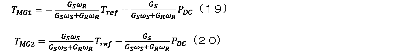
In the above formulas (17) and (18), by setting the axle torque T OUT to the value of the axle torque command Tref, the axle torque T OUT equal to the axle torque command Tref is realized and the voltage of the DC link is made constant. be able to.
第1インバータ制御部42は、トルク演算部120からトルク指令TMG1を受信し、トルク指令TMG1のトルクを出力するための制御(ベクトル制御など)を行い、第1インバータ40へのゲート指令を生成して出力する。
第2インバータ制御部52は、トルク演算部120からトルク指令TMG2を受信し、トルク指令TMG2のトルクを出力するための制御(ベクトル制御など)を行い、第2インバータ50へのゲート指令を生成して出力する。 The firstinverter control unit 42 receives the torque command T MG1 from the torque calculation unit 120, performs control (such as vector control) for outputting the torque of the torque command T MG1 , and issues a gate command to the first inverter 40. Generate and output.
The secondinverter control unit 52 receives the torque command T MG2 from the torque calculation unit 120, performs control (vector control or the like) for outputting the torque of the torque command T MG2 , and issues a gate command to the second inverter 50. Generate and output.
第2インバータ制御部52は、トルク演算部120からトルク指令TMG2を受信し、トルク指令TMG2のトルクを出力するための制御(ベクトル制御など)を行い、第2インバータ50へのゲート指令を生成して出力する。 The first
The second
上記のように生成したゲート指令により、第1インバータ40と第2インバータ50とが動作することにより、直流リンクにバッテリBTが接続されていないときでも、直流リンク電圧を一定に保ち、かつ、任意に設定された車軸トルク指令Trefを実現する出力トルクTOUTを車軸80から出力可能となる。すなわち、本実施形態の車両システムによれば、安定した駆動を実現することができる。
By operating the first inverter 40 and the second inverter 50 according to the gate command generated as described above, the DC link voltage is kept constant even when the battery BT is not connected to the DC link, and any The output torque T OUT that realizes the axle torque command Tref set to can be output from the axle 80. That is, according to the vehicle system of the present embodiment, stable driving can be realized.
次に、第2実施形態の車両システムについて図面を参照して説明する。
なお、以下の説明において、上述の第1実施形態と同様の構成については同一の符号を付して説明を省略する。 Next, the vehicle system of 2nd Embodiment is demonstrated with reference to drawings.
In the following description, the same components as those in the first embodiment described above are denoted by the same reference numerals and description thereof is omitted.
図5は、第2実施形態の車両システムの車両制御装置の構成例を概略的に示すブロック図である。
本実施形態では、車両制御装置CTRは複数のプロセッサを含み、発電機30を制御する発電機制御部MC2と、モータ60を制御するモータ制御部MC3と、統括制御部MC1とは、異なるプロセッサにより動作する。統括制御部MC1は、発電機制御部MC2およびモータ制御部MC3の両方と通信可能に構成されている。発電機制御部MC2とモータ制御部MC3とは互いに通信を行うことができない。発電機制御部MC2とモータ制御部MC3とは、統括制御部MC1の通信手段(図示せず)を介して通信を行うことができる。本実施形態では、上記のように複数のプロセッサを用いて発電機30とモータ60とを連携して制御する構成について説明する。 FIG. 5 is a block diagram schematically illustrating a configuration example of the vehicle control device of the vehicle system of the second embodiment.
In the present embodiment, the vehicle control device CTR includes a plurality of processors, and the generator control unit MC2 that controls thegenerator 30, the motor control unit MC3 that controls the motor 60, and the overall control unit MC1 are different processors. Operate. The overall control unit MC1 is configured to be able to communicate with both the generator control unit MC2 and the motor control unit MC3. The generator control unit MC2 and the motor control unit MC3 cannot communicate with each other. The generator control unit MC2 and the motor control unit MC3 can communicate with each other via communication means (not shown) of the overall control unit MC1. In the present embodiment, a configuration in which the generator 30 and the motor 60 are controlled in cooperation using a plurality of processors as described above will be described.
本実施形態では、車両制御装置CTRは複数のプロセッサを含み、発電機30を制御する発電機制御部MC2と、モータ60を制御するモータ制御部MC3と、統括制御部MC1とは、異なるプロセッサにより動作する。統括制御部MC1は、発電機制御部MC2およびモータ制御部MC3の両方と通信可能に構成されている。発電機制御部MC2とモータ制御部MC3とは互いに通信を行うことができない。発電機制御部MC2とモータ制御部MC3とは、統括制御部MC1の通信手段(図示せず)を介して通信を行うことができる。本実施形態では、上記のように複数のプロセッサを用いて発電機30とモータ60とを連携して制御する構成について説明する。 FIG. 5 is a block diagram schematically illustrating a configuration example of the vehicle control device of the vehicle system of the second embodiment.
In the present embodiment, the vehicle control device CTR includes a plurality of processors, and the generator control unit MC2 that controls the
本実施形態では、車両制御装置CTRは、発電機(第1電動機)30の回転角速度ωMG1とモータ(第2電動機)60の回転角速度ωMG2とに基づいて、直流リンクの電圧制御を行う電動機を選択し、発電機30の動作により直流リンクの電圧を制御するときに第1レベル(=1)となる第1制御信号CMD1と、モータ60の動作により直流リンクの電圧を制御するときに第1レベル(=1)となる第2制御信号CMD2と、を出力する直流電圧一定制御選択部130を更に備えている。例えば、発電機30の動作により直流リンクの電圧を制御するときは、第1制御信号CMD1が1となり、第2制御信号CMD2が0(第1レベルと異なる第2レベル)となる。モータ60の動作により直流リンクの電圧を制御するときには、第1制御信号CMD1が0(第2レベル)となり、第2制御信号CMD2が1となる。
In the present embodiment, the vehicle control device CTR is the generator rotational angular velocity omega MG1 and the motor (first motor) 30 on the basis of the rotational angular velocity omega MG2 (second electric motor) 60, an electric motor controls the voltage of the DC link When the DC link voltage is controlled by the operation of the generator 30, the first control signal CMD1 which becomes the first level (= 1), and when the DC link voltage is controlled by the operation of the motor 60, A DC voltage constant control selection unit 130 that outputs a second control signal CMD2 that becomes one level (= 1) is further provided. For example, when the voltage of the DC link is controlled by the operation of the generator 30, the first control signal CMD1 is 1 and the second control signal CMD2 is 0 (second level different from the first level). When the voltage of the DC link is controlled by the operation of the motor 60, the first control signal CMD1 becomes 0 (second level), and the second control signal CMD2 becomes 1.
上記のように、本実施形態では、第1直流電圧一定制御部110Aと第2直流電圧一定制御部110Bとのいずれか一方の出力信号に基づいて直流リンクの電圧を一定に制御するため、第1制御信号CMD1と第2制御信号CMD2とは排他的に1となる。例えば、第1直流電圧一定制御部110Aと第2直流電圧一定制御部110Bとの両方が、直流リンクの電圧一定制御を行うと、センサや回路における誤差により、直流リンクの電圧を上げようと制御する制御部と、直流リンクの電圧を下げようと制御する制御部とが生じ、第1直流電圧一定制御部110Aと第2直流電圧一定制御部110Bとの動作が破綻する可能性がある。
As described above, in the present embodiment, the voltage of the DC link is controlled to be constant based on the output signal of one of the first DC voltage constant controller 110A and the second DC voltage constant controller 110B. The 1 control signal CMD1 and the second control signal CMD2 become 1 exclusively. For example, when both the first DC voltage constant control unit 110A and the second DC voltage constant control unit 110B perform DC link voltage constant control, control is performed to increase the DC link voltage due to an error in a sensor or a circuit. There is a possibility that a control unit that performs control and a control unit that controls to lower the voltage of the DC link occurs, and the operations of the first DC voltage constant control unit 110A and the second DC voltage constant control unit 110B may fail.
例外として、車両システム全体が停止しているときには、第1制御信号CMD1と第2制御信号CMD2とがゼロ(=0)となる。車両システムが停止しているときには、インバータ制御部がゲート指令の出力を停止しており、停止シーケンスが動作するため、直流リンクの電圧はゼロ(=0)で安定することとなる。
Exceptionally, when the entire vehicle system is stopped, the first control signal CMD1 and the second control signal CMD2 are zero (= 0). When the vehicle system is stopped, the inverter control unit stops the output of the gate command, and the stop sequence operates. Therefore, the DC link voltage is stabilized at zero (= 0).
直流電圧一定制御部110は、第1直流電圧一定制御部(第1制御部)110Aと、第2直流電圧一定制御部(第2制御部)110Bと、第1切替器SWAと、第2切替器SWBと、を備えている。
The constant DC voltage controller 110 includes a first constant DC voltage controller (first controller) 110A, a second constant DC voltage controller (second controller) 110B, a first switch SWA, and a second switch. SWB.
第1直流電圧一定制御部110Aは、例えば、第1制御信号CMD1と、リンク間電圧指令VDCrefと、直流電圧VDCとを受信し、第1制御信号CMD1の値が第1レベル(=1)であるときに直流部エネルギーPDC1を演算して出力する。第1直流電圧一定制御部110Aは、第1制御信号CMD1の値が第2レベル(=0)であるときには、第1直流電圧一定制御部110Aの出力PDC1は、例えばゼロである。
For example, the first DC voltage constant control unit 110A receives the first control signal CMD1, the link voltage command V DCref, and the DC voltage V DC, and the value of the first control signal CMD1 is the first level (= 1). ), The direct current energy P DC1 is calculated and output. When the value of the first control signal CMD1 is the second level (= 0), the output DC1 of the first DC voltage constant control unit 110A is, for example, zero.
なお、CMD1=0であるときは、第1直流電圧一定制御部110Aの出力PDC1は、いずれの構成でも使用されないため、出力PDC1がどのような値であっても他の構成の動作に影響するものではなく、ゼロ以外の値に設定されても構わない。また、第1直流電圧一定制御部110Aは、リンク間電圧指令VDCrefと、直流電圧VDCとを受信し、直流部エネルギーPDC1を演算して出力するものであってもよい。すなわち、第1制御信号CMD1の値が第2レベル(=0)のときには、後述する第1切替器SWAが切り替わることにより、直流部エネルギーPDC1はいずれの構成でも使用されないため、第1制御信号CMD1に関わらず、第1直流電圧一定制御部110Aは直流部エネルギーPDC1を演算して出力するものであっても構わない。
When CMD1 = 0, the output P DC1 of the first DC voltage constant control unit 110A is not used in any configuration, so that the operation of other configurations can be performed regardless of the value of the output P DC1. It does not affect and may be set to a value other than zero. Further, the first DC voltage constant control unit 110A may receive the inter-link voltage command V DCref and the DC voltage V DC , calculate the DC unit energy P DC1 and output it. That is, when the value of the first control signal CMD1 is at the second level (= 0), the direct current energy P DC1 is not used in any configuration by switching a first switch SWA described later. Regardless of the CMD1, the first DC voltage constant control unit 110A may calculate and output the DC part energy PDC1 .
第2直流電圧一定制御部110Bは、第2制御信号CMD2と、リンク間電圧指令VDCrefと、直流電圧VDCとを受信し、第2制御信号CMD2の値が第1レベル(=1)であるときに直流部エネルギーPDC2を演算して出力する。第2直流電圧一定制御部110Bは、第2制御信号CMD2の値が第2レベル(=0)であるときには、第2直流電圧一定制御部110Bの出力PDC2は、例えばゼロである。
The second DC voltage constant control unit 110B receives the second control signal CMD2, the link voltage command V DCref, and the DC voltage V DC, and the value of the second control signal CMD2 is at the first level (= 1). At some time, the direct current energy P DC2 is calculated and output. In the second DC voltage constant control unit 110B, when the value of the second control signal CMD2 is the second level (= 0), the output P DC2 of the second DC voltage constant control unit 110B is, for example, zero.
なお、CMD2=0であるときは、第2直流電圧一定制御部110Bの出力PDC2は、いずれの構成でも使用されないため、出力PDC2がどのような値であっても他の構成の動作に影響するものではなく、ゼロ以外の値に設定されても構わない。また、第2直流電圧一定制御部110Bは、リンク間電圧指令VDCrefと、直流電圧VDCとを受信し、直流部エネルギーPDC2を演算して出力するものであってもよい。すなわち、第2制御信号CMD2の値が第2レベル(=0)のときには、後述する第2切替器SWBが切り替わることにより、直流部エネルギーPDC2はいずれの構成でも使用されないため、第2制御信号CMD2に関わらず、第2直流電圧一定制御部110Bは直流部エネルギーPDC2を演算して出力するものであっても構わない。
When CMD2 = 0, the output P DC2 of the second DC voltage constant control unit 110B is not used in any configuration, so that the operation of other configurations can be performed regardless of the value of the output P DC2. It does not affect and may be set to a value other than zero. The second DC voltage constant control unit 110B may receive the inter-link voltage command V DCref and the DC voltage V DC, and calculate and output the DC unit energy P DC2 . That is, when the value of the second control signal CMD2 is at the second level (= 0), the second switch SWB, which will be described later, is switched so that the direct current energy PDC2 is not used in any configuration. regardless CMD2, the second DC voltage constant control unit 110B may be one which calculates and outputs the DC unit energy P DC2.
第1切替器SWAは、第1入力端子に第1直流電圧一定制御部110Aの出力PDC1が入力され、第2入力端子に第2直流電圧一定制御部110Bの出力PDC2が入力される。第1切替器SWAは、第1制御信号CMD1が第1レベル(=1)のときに第1入力端子と出力端子とを接続する。第1切替器SWAは、第1制御信号CMD1が第2レベル(=0)のときに第2入力端子と出力端子とを接続する。
In the first switch SWA, the output P DC1 of the first DC voltage constant control unit 110A is input to the first input terminal, and the output P DC2 of the second DC voltage constant control unit 110B is input to the second input terminal. The first switch SWA connects the first input terminal and the output terminal when the first control signal CMD1 is at the first level (= 1). The first switch SWA connects the second input terminal and the output terminal when the first control signal CMD1 is at the second level (= 0).
第2切替器SWBは、第3入力端子に第2直流電圧一定制御部110Bの出力PDC2が入力され、第4入力端子に第1直流電圧一定制御部110Aの出力PDC1が入力される。第2切替器SWBは、第2制御信号CMD2が第1レベル(=1)のときに第3入力端子と出力端子とを接続する。第2切替器SWBは、第2制御信号CMD2が第2レベル(=0)のときに第4入力端子と出力端子とを接続する。
In the second switch SWB, the output P DC2 of the second DC voltage constant control unit 110B is input to the third input terminal, and the output P DC1 of the first DC voltage constant control unit 110A is input to the fourth input terminal. The second switch SWB connects the third input terminal and the output terminal when the second control signal CMD2 is at the first level (= 1). The second switch SWB connects the fourth input terminal and the output terminal when the second control signal CMD2 is at the second level (= 0).
トルク演算部120は、部分トルク演算部120´と、第1演算部140Aと、第1加算器150Aと、第2演算部140Bと、第2加算器150Bと、を備えている。
部分トルク演算部120´は、車軸トルク指令Trefを受信し、上述の式(19)の車軸トルク指令Trefに関する項(第1演算項)と、上述の式(20)の車軸トルク指令Trefに関する項(第3演算項)とを演算する。第1演算部140Aは、第1切替器SWAから出力される値を受信し、上述の式(19)の直流部エネルギーPDCに関する項(第2演算項)を演算する。第1加算器150Aは、上記第1演算項と第2演算項とを加算して出力する。第2演算部140Bは、第2切換器SWBから出力される値を受信し、上述の式(20)の直流部エネルギーPDCに関する項(第4演算項)を演算する。第2加算器150Bは、上記第3演算項と第4演算項とを加算して出力する。 Thetorque calculation unit 120 includes a partial torque calculation unit 120 ′, a first calculation unit 140A, a first adder 150A, a second calculation unit 140B, and a second adder 150B.
The partialtorque calculation unit 120 ′ receives the axle torque command Tref, and a term (first calculation term) relating to the axle torque command Tref in the above equation (19) and a term relating to the axle torque command Tref in the above equation (20). (Third operation term) is calculated. First operation unit 140A receives the value output from the first switch SWA, computes the term (second operand) regarding the DC unit energy P DC of the aforementioned formula (19). The first adder 150A adds the first calculation term and the second calculation term and outputs the result. The second calculation unit 140B receives the value output from the second switch SWB, and calculates a term (fourth calculation term) related to the direct current energy P DC in the above-described equation (20). The second adder 150B adds the third calculation term and the fourth calculation term and outputs the result.
部分トルク演算部120´は、車軸トルク指令Trefを受信し、上述の式(19)の車軸トルク指令Trefに関する項(第1演算項)と、上述の式(20)の車軸トルク指令Trefに関する項(第3演算項)とを演算する。第1演算部140Aは、第1切替器SWAから出力される値を受信し、上述の式(19)の直流部エネルギーPDCに関する項(第2演算項)を演算する。第1加算器150Aは、上記第1演算項と第2演算項とを加算して出力する。第2演算部140Bは、第2切換器SWBから出力される値を受信し、上述の式(20)の直流部エネルギーPDCに関する項(第4演算項)を演算する。第2加算器150Bは、上記第3演算項と第4演算項とを加算して出力する。 The
The partial
車両制御装置CTRは、統括制御部MC1、発電機制御部MC2、および、モータ制御部MC3を含んでいる。統括制御部MC1と発電機制御部MC2とモータ制御部MC3とは、互いに異なるプロセッサにより動作する構成である。
The vehicle control device CTR includes an overall control unit MC1, a generator control unit MC2, and a motor control unit MC3. The overall control unit MC1, the generator control unit MC2, and the motor control unit MC3 are configured to operate by different processors.
統括制御部MC1は、回転数決定部100と、部分トルク演算部120´と、直流電圧一定制御選択部130と、を備えている。
回転数決定部100は、上述の第1実施形態と同様に、例えば、車軸80の出力トルクに対応する内燃機関10の回転数を格納したテーブルを備えている。回転数決定部100は、外部から供給される車軸トルク指令Trefを受信し、車軸トルク指令Trefに対応する内燃機関10の回転数をテーブルから読み出して出力する。 The overall control unit MC1 includes a rotationspeed determination unit 100, a partial torque calculation unit 120 ′, and a DC voltage constant control selection unit 130.
The rotationalspeed determination unit 100 includes a table that stores the rotational speed of the internal combustion engine 10 corresponding to the output torque of the axle 80, for example, as in the first embodiment. The rotational speed determination unit 100 receives an axle torque command Tref supplied from the outside, reads out the rotational speed of the internal combustion engine 10 corresponding to the axle torque command Tref from the table, and outputs it.
回転数決定部100は、上述の第1実施形態と同様に、例えば、車軸80の出力トルクに対応する内燃機関10の回転数を格納したテーブルを備えている。回転数決定部100は、外部から供給される車軸トルク指令Trefを受信し、車軸トルク指令Trefに対応する内燃機関10の回転数をテーブルから読み出して出力する。 The overall control unit MC1 includes a rotation
The rotational
部分トルク演算部120´は、外部から供給される車軸トルク指令Trefを受信し、上述の式(19)、(20)により演算されるトルク指令TMG1、TMG2の車軸トルク指令Trefに関する項(上述の第1演算項と第3演算項)に相当する下記の部分トルク指令TMG1´、TMG2´を演算して出力する。
The partial torque calculation unit 120 ′ receives the axle torque command Tref supplied from the outside, and a term related to the axle torque command Tref of the torque commands T MG1 and T MG2 calculated by the above formulas (19) and (20) ( The following partial torque commands T MG1 ′ and T MG2 ′ corresponding to the above-described first calculation term and third calculation term) are calculated and output.

本実施形態では、直流リンクは、第1電動機である発電機30を駆動する第1インバータ40と、第2電動機であるモータ60を駆動する第2インバータ50との間に接続していることから、発電機30の動作とモータ60の動作とのいずれか一方により定電圧制御を行うことが可能である。
In the present embodiment, the DC link is connected between the first inverter 40 that drives the generator 30 that is the first electric motor and the second inverter 50 that drives the motor 60 that is the second electric motor. The constant voltage control can be performed by either the operation of the generator 30 or the operation of the motor 60.
電動機は、一般的に出力可能なトルクに限界がある。電動機が角速度ωで回転しているときに出力可能な最大トルクTMAXとすれば、角速度ωと最大トルクTMAXとの積が大きい電動機の方が、より直流リンクの電圧制御に対する余力を有していることとなる。
上記のことから、直流電圧一定制御選択部130は、発電機30の回転角速度ωMG1と最大トルクTMAX-MG1との積と、モータ60の回転角速度ωMG2と最大トルクTMAX-MG2との積とを比較して、回転角速度と最大トルクとの積が大きい方の電動機を用いて、直流リンクの電圧制御を行うように第1制御信号CMD1と第2制御信号CMD2とを出力する。 An electric motor generally has a limit in the torque that can be output. If the maximum torque T MAX that can be output when the motor is rotating at the angular velocity ω is set, the motor having a larger product of the angular velocity ω and the maximum torque T MAX has more reserve power for DC link voltage control. Will be.
From the above, the constant DC voltagecontrol selection unit 130 calculates the product of the rotational angular speed ω MG1 of the generator 30 and the maximum torque T MAX-MG1, and the rotational angular speed ω MG2 and the maximum torque T MAX-MG2 of the motor 60. The first control signal CMD1 and the second control signal CMD2 are output so as to perform voltage control of the DC link using the motor having the larger product of the rotational angular velocity and the maximum torque.
上記のことから、直流電圧一定制御選択部130は、発電機30の回転角速度ωMG1と最大トルクTMAX-MG1との積と、モータ60の回転角速度ωMG2と最大トルクTMAX-MG2との積とを比較して、回転角速度と最大トルクとの積が大きい方の電動機を用いて、直流リンクの電圧制御を行うように第1制御信号CMD1と第2制御信号CMD2とを出力する。 An electric motor generally has a limit in the torque that can be output. If the maximum torque T MAX that can be output when the motor is rotating at the angular velocity ω is set, the motor having a larger product of the angular velocity ω and the maximum torque T MAX has more reserve power for DC link voltage control. Will be.
From the above, the constant DC voltage
本実施形態では、直流電圧一定制御選択部130は、例えば、ωMG1TMAX-MG1>ωMG2TMAX-MG2のときには、第1制御信号CMD1が「1」、第2制御信号CMD2が「0」とし、ωMG1TMAX-MG1≦ωMG2TMAX-MG2のときには、第1制御信号CMD1が「0」、第2制御信号CMD2が「1」とする。なお、第1制御信号CMD1と第2制御信号CMD2とは、例えば、値が「0」のときに電圧制御の停止要求を示し、値が「1」のときに電圧制御の動作要求を示す。
In the present embodiment, for example, when ω MG1 T MAX-MG1 > ω MG2 T MAX-MG2 is set, the first control signal CMD1 is “1” and the second control signal CMD2 is “0”. When ω MG1 T MAX-MG1 ≦ ω MG2 T MAX-MG2 , the first control signal CMD1 is “0” and the second control signal CMD2 is “1”. The first control signal CMD1 and the second control signal CMD2 indicate, for example, a voltage control stop request when the value is “0” and a voltage control operation request when the value is “1”.
なお、上述の式(5)より、サンギアSとリングギアRとの速度の増減方向は、互いに反対方向となっているため、発電機30の速度が減少しているときにはモータ60の速度が増加し、発電機30の速度が増加しているときにはモータ60の速度が減少していることとなる。このことから、内燃機関10が動作している状況において、発電機30とモータ60とのいずれか一方にて、直流リンクの電圧制御が可能な状態となっている。
From the above equation (5), since the speed increasing / decreasing directions of the sun gear S and the ring gear R are opposite to each other, the speed of the motor 60 increases when the speed of the generator 30 decreases. However, when the speed of the generator 30 is increasing, the speed of the motor 60 is decreasing. From this, in a situation where the internal combustion engine 10 is operating, either one of the generator 30 and the motor 60 is in a state where voltage control of the DC link is possible.
発電機制御部MC2は、第1直流電圧一定制御部110Aと、第1演算部140Aと、第1加算器150Aと、第1インバータ制御部42と、第1切替器SWAと、を備えている。
The generator control unit MC2 includes a first DC voltage constant control unit 110A, a first calculation unit 140A, a first adder 150A, a first inverter control unit 42, and a first switch SWA. .
第1直流電圧一定制御部110Aは、第1制御信号CMD1と、直流リンクの電圧の目標値VDCrefと直流電圧検出値VDCとを受信し、第1制御信号CMD1の値が「1」のときに、第1実施形態の直流電圧一定制御部110と同様に、リンク間電圧指令VDCrefと直流電圧検出値VDCとの差がゼロとなるように、直流部エネルギーPDC1の値を演算して出力する。直流部エネルギーPDC1は、統括制御部MC1を介して、切替器SWAの入力端子の一方と、後述する切替器SWBの入力端子の他方とへ供給される。
The first DC voltage constant control unit 110A receives the first control signal CMD1, the DC link voltage target value V DCref and the DC voltage detection value V DC, and the value of the first control signal CMD1 is “1”. Sometimes, as in the DC voltage constant control unit 110 of the first embodiment, the value of the DC unit energy P DC1 is calculated so that the difference between the link voltage command V DCref and the DC voltage detection value V DC becomes zero. And output. The direct current energy PDC1 is supplied to one of the input terminals of the switch SWA and the other input terminal of the switch SWB described later via the overall control unit MC1.
第1切替器SWAは、2つの入力端子(第1入力端子および第2入力端子)と1つの出力端子とを有し、第1制御信号CMD1の値に応じて第1入力端子と第2入力端子とのいずれかが出力端子と電気的に接続するように切り替える。切替器SWAは、第1制御信号CMD1の値が「1」のときに第1入力端子と出力端子とを電気的に接続し、制御信号CMD1の値が「0」のときに第2入力端子と出力端子とを電気的に接続する。
The first switch SWA has two input terminals (first input terminal and second input terminal) and one output terminal, and the first input terminal and the second input according to the value of the first control signal CMD1. Switch so that one of the terminals is electrically connected to the output terminal. The switch SWA electrically connects the first input terminal and the output terminal when the value of the first control signal CMD1 is “1”, and the second input terminal when the value of the control signal CMD1 is “0”. Are electrically connected to the output terminal.
第1演算部140Aは、切替器SWAから直流部エネルギーPDC1と直流部エネルギーPDC2とのいずれか一方を受信し、上述の式(19)、(20)により演算されるトルク指令TMG1の直流部エネルギーPDCに関する項(上記第2演算項)に相当する下記の定電圧指令AVR1を第1加算器150Aへ出力する。
First operation unit 140A receives one of the DC portion energy P DC2 to the DC unit energy P DC1 from switch SWA, the above equation (19), a DC torque command TMG1 that is calculated by (20) The following constant voltage command AVR1 corresponding to a term related to the partial energy PDC (the second calculation term) is output to the first adder 150A.
第1インバータ制御部42は、上述の第1実施形態と同様に、トルク指令TMG1を受信し、トルク指令TMG1のトルクを出力するための制御(ベクトル制御など)を行い、第1インバータ40へのゲート指令を生成して出力する。
The first inverter control unit 42, similarly to the first embodiment described above, receives the torque command T MG1, and controls (such as vector control) for outputting the torque of the torque command T MG1, first inverter 40 Generate and output a gate command to.
モータ制御部MC3は、第2直流電圧一定制御部110Bと、第2演算部140Bと、第2加算器150Bと、第2インバータ制御部52と、第2切替器SWBと、を備えている。
The motor control unit MC3 includes a second DC voltage constant control unit 110B, a second calculation unit 140B, a second adder 150B, a second inverter control unit 52, and a second switch SWB.
第2直流電圧一定制御部110Bは、第2制御信号CMD2と、直流リンクの電圧の目標値VDCrefと直流電圧検出値VDCとを受信し、第2制御信号CMD2の値が「1」のときに、第1実施形態の直流電圧一定制御部110と同様に、リンク間電圧指令VDCrefと直流電圧検出値VDCとの差がゼロとなるように、直流部エネルギーPDC2の値を演算して出力する。直流部エネルギーPDC2は、統括制御部MC1を介して、第2切替器SWBの第3入力端子と、上述の切替器SWAの第2入力端子とへ供給される。
The second DC voltage constant control unit 110B receives the second control signal CMD2, the DC link voltage target value V DCref and the DC voltage detection value V DC, and the value of the second control signal CMD2 is “1”. Sometimes, as in the DC voltage constant control unit 110 of the first embodiment, the value of the DC unit energy P DC2 is calculated so that the difference between the link voltage command V DCref and the DC voltage detection value V DC becomes zero. And output. The direct current unit energy PDC2 is supplied to the third input terminal of the second switch SWB and the second input terminal of the switch SWA described above via the overall control unit MC1.
第2切替器SWBは、2つの入力端子(第3入力端子および第4入力端子)と1つの出力端子とを有し、第2制御信号CMD2の値に応じて第3入力端子と第4入力端子とのいずれかが出力端子と電気的に接続するように切り替える。第2切替器SWBは、第2制御信号CMD2の値が「1」のときに第3入力端子と出力端子とを電気的に接続し、第2制御信号CMD2の値が「0」のときに第4入力端子と出力端子とを電気的に接続する。
The second switch SWB has two input terminals (a third input terminal and a fourth input terminal) and one output terminal, and the third input terminal and the fourth input according to the value of the second control signal CMD2. Switch so that one of the terminals is electrically connected to the output terminal. The second switch SWB electrically connects the third input terminal and the output terminal when the value of the second control signal CMD2 is “1”, and when the value of the second control signal CMD2 is “0”. The fourth input terminal and the output terminal are electrically connected.
第2演算部140Bは、第2切替器SWBから直流部エネルギーPDC2と直流部エネルギーPDC1とのいずれか一方を受信し、上述の式(19)、(20)により演算されるトルク指令TMG2の直流部エネルギーPDCに関する項(上記第4演算項)に相当する下記の定電圧指令AVR2を加算器150Bへ出力する。
The second calculation unit 140B receives either one of the direct current energy P DC2 and the direct current energy P DC1 from the second switch SWB, and calculates the torque command T calculated by the above equations (19) and (20). The following constant voltage command AVR2 corresponding to the term relating to the DC part energy PDC of MG2 (the fourth arithmetic term) is output to adder 150B.
第2インバータ制御部52は、上述の第1実施形態と同様に、トルク指令TMG2を受信し、トルク指令TMG2のトルクを出力するための制御(ベクトル制御など)を行い、第2インバータ50へのゲート指令を生成して出力する。
The second inverter control unit 52, similarly to the first embodiment described above, receives the torque command T MG2, and controls (such as vector control) for outputting the torque of the torque command T MG2, the second inverter 50 Generate and output a gate command to.
したがって、発電機30の動作により直流リンクの電圧が一定になるように制御するときには、トルク指令TMG1、TMG2は下記のように表すことができる。

Therefore, when controlling the DC link voltage to be constant by the operation of the generator 30, the torque commands T MG1 and T MG2 can be expressed as follows.
モータ60の動作により直流リンクの電圧が一定になるように制御するときには、トルク指令TMG1、TMG2は下記のように表すことができる。
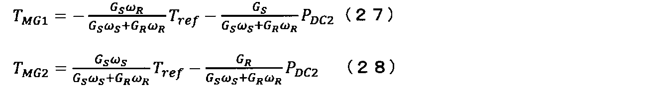
When controlling the DC link voltage to be constant by the operation of the motor 60, the torque commands T MG1 and T MG2 can be expressed as follows.
上述の第1実施形態では、直流電圧一定制御部110の出力(直流部エネルギーPDC)が、第1インバータ制御部42および第2インバータ制御部52へ遅延なく送られるときには、補機90の消費エネルギーの変動に追従することが可能である。しかしながら、例えば、発電機30を制御する構成と、モータ60を制御する構成とが、互いに異なるプロセッサにより動作するときには、互いの構成への指令に遅延が発生するため、トルク応答が遅れることとなる。
In the above-described first embodiment, when the output of the DC voltage constant control unit 110 (DC unit energy P DC ) is sent to the first inverter control unit 42 and the second inverter control unit 52 without delay, the consumption of the auxiliary machine 90 is performed. It is possible to follow energy fluctuations. However, for example, when the configuration for controlling the generator 30 and the configuration for controlling the motor 60 are operated by different processors, a delay occurs in the command to each configuration, and thus the torque response is delayed. .
例えば、発電機30が定速回転しているときに発電機30の動作により直流リンクの定電圧制御を行うと、補機90の消費エネルギーが変化した場合、発電機30は低速回転しているために大きなエネルギーを生成することができず、補機90の消費エネルギー変化に追従できない可能性がある。
一方で、モータ60は、発電機30の制御部とモータ60の制御部との通信遅延により、直流部エネルギーの値が即時に送られず、補機の消費エネルギー変化に即時に追従することができない可能性がある。これらの場合には、直流リンクの電圧が変動してしまうため、車両システム全体の動作が停止する可能性がある。 For example, when the DC link constant voltage control is performed by the operation of thegenerator 30 when the generator 30 is rotating at a constant speed, the generator 30 is rotating at a low speed when the energy consumption of the auxiliary machine 90 changes. Therefore, large energy cannot be generated, and there is a possibility that it cannot follow the energy consumption change of the accessory 90.
On the other hand, themotor 60 may immediately follow the change in energy consumption of the auxiliary device due to a communication delay between the control unit of the generator 30 and the control unit of the motor 60, and the value of the DC unit energy is not sent immediately. It may not be possible. In these cases, since the voltage of the DC link varies, the operation of the entire vehicle system may stop.
一方で、モータ60は、発電機30の制御部とモータ60の制御部との通信遅延により、直流部エネルギーの値が即時に送られず、補機の消費エネルギー変化に即時に追従することができない可能性がある。これらの場合には、直流リンクの電圧が変動してしまうため、車両システム全体の動作が停止する可能性がある。 For example, when the DC link constant voltage control is performed by the operation of the
On the other hand, the
本実施形態の車両システムによれば、発電機30とモータ60との動作状態(回転角速度と最大トルクとの積)に応じて、発電機30とモータ60とのどちら電動機の動作により直流リンクの電圧制御を行うかを決定するため、安定した直流リンク電圧制御を実現することができる。また、電圧制御を行っていない電動機の制御部は、電圧制御を行っている電動機の制御部から直流部エネルギーPDCを受信することにより、直流リンクの電圧が変化したときにも追従することが可能となる。
なお、本実施形態では、発電機30を制御する構成と、モータ60とを制御する構成とが互いに異なるプロセッサにより動作する際の通信遅延が生じたとしても、10ms~100ms程度である。すなわち、本実施形態の車両システムによれば、安定した駆動を実現することができる。 According to the vehicle system of this embodiment, depending on the operating state of thegenerator 30 and the motor 60 (the product of the rotational angular velocity and the maximum torque), the operation of the generator of either the generator 30 or the motor 60 depends on the operation of the DC link. Since it is determined whether to perform voltage control, stable DC link voltage control can be realized. The control unit of the electric motor is not performed a voltage control by receiving the DC link energy P DC from the control unit of the motor is performing a voltage control, it can follow even when the voltage of the DC link has changed It becomes possible.
In the present embodiment, even if a communication delay occurs when the configuration for controlling thegenerator 30 and the configuration for controlling the motor 60 are operated by different processors, it is about 10 ms to 100 ms. That is, according to the vehicle system of the present embodiment, stable driving can be realized.
なお、本実施形態では、発電機30を制御する構成と、モータ60とを制御する構成とが互いに異なるプロセッサにより動作する際の通信遅延が生じたとしても、10ms~100ms程度である。すなわち、本実施形態の車両システムによれば、安定した駆動を実現することができる。 According to the vehicle system of this embodiment, depending on the operating state of the
In the present embodiment, even if a communication delay occurs when the configuration for controlling the
なお、上記第2実施形態では、直流電圧一定制御選択部130は、回転角速度と最大トルクの積の値が大きい方の電動機が電圧制御を行うものとしたが、回転角速度のみを比較して、回転角速度が大きい方の電動機が電圧制御を行うものとして選択しても構わない。その場合であっても、上述の第2実施形態と同様の効果を得ることができ、例えば回転角速度のセンサを備えない車両であっても本実施形態を適用することができる。
In the second embodiment, the DC voltage constant control selection unit 130 performs voltage control on the motor having the larger value of the product of the rotational angular velocity and the maximum torque, but only the rotational angular velocity is compared, You may select as an electric motor with a larger rotational angular velocity performing voltage control. Even in that case, the same effects as those of the second embodiment described above can be obtained. For example, the present embodiment can be applied even to a vehicle that does not include a rotational angular velocity sensor.
次に、第3実施形態の車両システムについて、図面を参照して説明する。
本実施形態の車両システムは、車両が停止しているとき、すなわち発電機30が停止しているときの動作を考慮した構成を備えている。 Next, the vehicle system of 3rd Embodiment is demonstrated with reference to drawings.
The vehicle system of the present embodiment has a configuration that takes into account the operation when the vehicle is stopped, that is, when thegenerator 30 is stopped.
本実施形態の車両システムは、車両が停止しているとき、すなわち発電機30が停止しているときの動作を考慮した構成を備えている。 Next, the vehicle system of 3rd Embodiment is demonstrated with reference to drawings.
The vehicle system of the present embodiment has a configuration that takes into account the operation when the vehicle is stopped, that is, when the
図6は、第3実施形態の車両システムの車両制御装置の構成を概略的に示すブロック図である。
制御装置CTRは、第1実施形態の車両システムにおける制御装置CTRに、車両停車判定部150を更に備えた構成である。 FIG. 6 is a block diagram schematically showing the configuration of the vehicle control device of the vehicle system of the third embodiment.
The control device CTR is configured to further include a vehiclestop determination unit 150 in the control device CTR in the vehicle system of the first embodiment.
制御装置CTRは、第1実施形態の車両システムにおける制御装置CTRに、車両停車判定部150を更に備えた構成である。 FIG. 6 is a block diagram schematically showing the configuration of the vehicle control device of the vehicle system of the third embodiment.
The control device CTR is configured to further include a vehicle
車両停車判定部150は、外部から供給されたブレーキ状態と、車軸トルク指令Trefと、車両走行速度ωRと、を受信し、第2インバータ制御部52へ停止指令を出力する。車両停車判定部150は、ブレーキが入れられている状態であり、車軸トルク指令Trefの値が「0」であり、車両走行速度が「0」であるときに、車両が停車しているものと判断し、停止指令を「1」とし、上記の条件が満たされないときには停車指令を「0」とする。
Vehicle stop determination unit 150 receives a brake state supplied from the outside, and the axle torque command Tref, and the vehicle traveling speed omega R, and outputs a stop command to the second inverter control unit 52. The vehicle stop determination unit 150 is in a state where the brake is applied, and when the value of the axle torque command Tref is “0” and the vehicle traveling speed is “0”, the vehicle is stopped. The stop command is set to “1”, and the stop command is set to “0” when the above condition is not satisfied.
第2インバータ制御部52は、車両停車判定部150から入力される停止指令の値が「1」のときに、第2インバータ50の動作を停止する。すなわち、第2インバータ制御部52は、トルク演算部120から入力されるトルク指令TMG2の値に関わらず、トルク指令TMG2=0として第2インバータ50へゲート指令を出力する。
The second inverter control unit 52 stops the operation of the second inverter 50 when the value of the stop command input from the vehicle stop determination unit 150 is “1”. That is, the second inverter control unit 52 outputs a gate command to the second inverter 50 as the torque command T MG2 = 0 regardless of the value of the torque command T MG2 input from the torque calculation unit 120.
車両が停車しているときには、車軸80の出力トルクTOUT(=Tref)=0であるため、式(19)、(20)より発電機30のトルク指令TMG1と、モータ60のトルク指令TMG2は下記のように表すことができる。
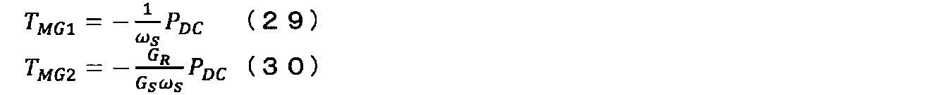
Since the output torque T OUT (= Tref) = 0 of the axle 80 when the vehicle is stopped, the torque command T MG1 of the generator 30 and the torque command T of the motor 60 are obtained from the equations (19) and (20). MG2 can be expressed as follows.
モータ60は車軸80と連結しているため、車両が停車しているときには、モータの回転角速度ωMG2=0となる。したがって、車両が停車しているときには、モータ60は、直流リンクにエネルギーを供給することがないため、モータ60は直流リンクの電圧制御に影響しない。さらに、車両のブレーキ機構(図示せず)が動作している状態では、モータ60で生じるトルクをブレーキ機構が代わりに負担することとなる。そのため、車両が停車しているときには、第2インバータ50は動作停止してもよく、不要な動作を行わないことにより、故障率を低下することができるとともに、モータ60および第2インバータ50の電気的エネルギー損失による温度上昇を抑制することができる。すなわち、本実施形態の車両システムによれば、安定した駆動を実現することができる。
Since the motor 60 is connected to the axle 80, the rotational angular velocity ω MG2 of the motor is 0 when the vehicle is stopped. Therefore, when the vehicle is stopped, the motor 60 does not supply energy to the DC link, so the motor 60 does not affect the voltage control of the DC link. Furthermore, when the vehicle brake mechanism (not shown) is operating, the brake mechanism bears the torque generated by the motor 60 instead. Therefore, when the vehicle is stopped, the second inverter 50 may stop operating, and by not performing unnecessary operations, the failure rate can be reduced and the electric power of the motor 60 and the second inverter 50 can be reduced. Temperature rise due to dynamic energy loss can be suppressed. That is, according to the vehicle system of the present embodiment, stable driving can be realized.
すなわち、本実施形態では、停止指令の値が「1」のとき、トルク指令TMG1、TMG2は下記のようになる。

That is, in this embodiment, when the value of the stop command is “1”, the torque commands T MG1 and T MG2 are as follows.
図7は、第3実施形態の車両システムの車両制御装置の他の構成例を概略的に示すブロック図である。
この例では、車両制御装置CTRは、第2実施形態の車両システムにおける車両制御装置に、車両停車判定部150を更に備えた構成である。 FIG. 7 is a block diagram schematically showing another configuration example of the vehicle control device of the vehicle system of the third embodiment.
In this example, the vehicle control device CTR is configured to further include a vehiclestop determination unit 150 in the vehicle control device in the vehicle system of the second embodiment.
この例では、車両制御装置CTRは、第2実施形態の車両システムにおける車両制御装置に、車両停車判定部150を更に備えた構成である。 FIG. 7 is a block diagram schematically showing another configuration example of the vehicle control device of the vehicle system of the third embodiment.
In this example, the vehicle control device CTR is configured to further include a vehicle
この例においても、車両停車判定部150は、外部から供給されたブレーキ状態と、トルク指令Trefと、車両走行速度ωRと、を受信し、第2インバータ制御部52へ停止指令を出力する。車両停車判定部150は、ブレーキが入れられている状態であり、車軸トルク指令Trefの値が「0」であり、車両走行速度が「0」であるときに、車両が停車しているものと判断し、停止指令を「1」とし、上記の条件が満たされないときには停車指令を「0」とする。
Also in this example, the vehicle stop determination unit 150 receives the brake state supplied from the outside, the torque command Tref, and the vehicle travel speed ωR, and outputs a stop command to the second inverter control unit 52. The vehicle stop determination unit 150 is in a state where the brake is applied, and when the value of the axle torque command Tref is “0” and the vehicle traveling speed is “0”, the vehicle is stopped. The stop command is set to “1”, and the stop command is set to “0” when the above condition is not satisfied.
第2インバータ制御部52は、車両停車判定部150から入力される停止指令の値が「1」のときに、第2インバータ50の動作を停止する。すなわち、第2インバータ制御部52は、トルク演算部120から入力されるトルク指令TMG2の値に関わらず、トルク指令TMG2=0として第2インバータ50へゲート指令を出力する。
The second inverter control unit 52 stops the operation of the second inverter 50 when the value of the stop command input from the vehicle stop determination unit 150 is “1”. That is, the second inverter control unit 52, regardless of the value of the torque command T MG2 inputted from the torque computing unit 120, and outputs a gate command to the second inverter 50 as the torque command TMG2 = 0.
すなわち、この例では、停止指令が「1」のとき、には、上述の式(25)、(26)により下記のように表すことができる。

上記のように、本実施形態の車両システムによれば、安定した駆動を実現することができる。
That is, in this example, when the stop command is “1”, it can be expressed as follows by the above-described equations (25) and (26).
As described above, according to the vehicle system of the present embodiment, stable driving can be realized.
本発明のいくつかの実施形態を説明したが、これらの実施形態は、例として提示したものであり、発明の範囲を限定することは意図していない。これら新規な実施形態は、その他の様々な形態で実施されることが可能であり、発明の要旨を逸脱しない範囲で、種々の省略、置き換え、変更を行うことができる。これら実施形態やその変形は、発明の範囲や要旨に含まれるとともに、特許請求の範囲に記載された発明とその均等の範囲に含まれる。
Although several embodiments of the present invention have been described, these embodiments are presented as examples and are not intended to limit the scope of the invention. These novel embodiments can be implemented in various other forms, and various omissions, replacements, and changes can be made without departing from the scope of the invention. These embodiments and modifications thereof are included in the scope and gist of the invention, and are included in the invention described in the claims and the equivalents thereof.
Claims (4)
- 内燃機関と、
第1電動機と、
第2電動機と、
前記内燃機関の回転運動を、前記第1電動機と第2動力伝達機構とに伝達する第1動力伝達機構と、
前記第2動力伝達機構と連結され回転する車軸と、
前記第2動力伝達機構は、前記第2電動機と前記車軸との間、および、前記第1動力伝達機構と前記車軸との間で回転運動を伝達し、
前記第1電動機を駆動する第1インバータと、
直流リンクを介して前記第1インバータと接続し、前記第2電動機を駆動する第2インバータと、
前記直流リンクのリンク間電圧を検出する電圧検出器と、
外部から供給されるリンク間電圧指令と、前記リンク間電圧とが等しくなるように、直流部エネルギーを出力する直流電圧一定制御部と、
外部から供給される車軸トルク指令と、前記直流部エネルギーとを受信し、前記車軸の出力トルクが前記車軸トルク指令と等しく、かつ、前記直流リンクの電圧が一定となるように、前記第1電動機のトルク指令と、前記第2電動機のトルク指令とを演算するトルク演算部と、
前記第1電動機のトルク指令に基づいて前記第1インバータへゲート指令を出力する第1インバータ制御部と、
前記第2電動機のトルク指令に基づいて前記第2インバータへゲート指令を出力する第2インバータ制御部と、
を備えた車両システム。 An internal combustion engine;
A first electric motor;
A second electric motor;
A first power transmission mechanism that transmits the rotational motion of the internal combustion engine to the first electric motor and a second power transmission mechanism;
An axle connected to the second power transmission mechanism and rotating;
The second power transmission mechanism transmits rotational motion between the second electric motor and the axle, and between the first power transmission mechanism and the axle,
A first inverter that drives the first motor;
A second inverter connected to the first inverter via a DC link and driving the second motor;
A voltage detector for detecting a voltage between links of the DC link;
DC voltage constant control unit that outputs DC unit energy so that the link-to-link voltage command supplied from the outside is equal to the link-to-link voltage,
The first electric motor receives an axle torque command supplied from the outside and the direct current energy, the output torque of the axle is equal to the axle torque command, and the voltage of the DC link is constant. A torque calculation unit for calculating a torque command of the second motor and a torque command of the second motor;
A first inverter control unit that outputs a gate command to the first inverter based on a torque command of the first motor;
A second inverter control unit that outputs a gate command to the second inverter based on a torque command of the second motor;
Vehicle system equipped with. - 前記第1動力伝達機構は、前記内燃機関で生成されたエネルギーにより回転するプラネタリアキャリアと、前記第1電動機へ回転動力を伝達するサンギアと、前記第2動力伝達機構へ回転動力を伝達するリングギアと、を備え、
前記第1電動機のトルク指令は、前記サンギアの歯数と前記リングギアの回転角速度と前記車軸トルク指令との積を、前記サンギアの歯数と前記サンギアの回転角速度との積と前記リングギアの歯数と前記リングギアの回転角速度との積との和で除した値を負とした第1演算項と、前記サンギアの歯数と前記直流部エネルギーとの積を、前記サンギアの歯数と前記サンギアの回転角速度との積と前記リングギアの歯数と前記リングギアの回転角速度との積との和で除した値を負とした第2演算項と、が加算された値であり、
前記第2電動機のトルク指令は、前記サンギアの歯数と前記サンギアの回転角速度と前記車軸トルク指令との積を、前記サンギアの歯数と前記サンギアの回転角速度との積と前記リングギアの歯数と前記リングギアの回転角速度との積との和で除した第3演算項と、前記サンギアの歯数と前記直流部エネルギーとの積を、前記サンギアの歯数と前記サンギアの回転角速度との積と前記リングギアの歯数と前記リングギアの回転角速度との積との和で除した値を負とした第4演算項と、が加算された値である請求項1記載の車両システム。 The first power transmission mechanism includes a planetary carrier that rotates by energy generated by the internal combustion engine, a sun gear that transmits rotational power to the first motor, and a ring that transmits rotational power to the second power transmission mechanism. And gears,
The torque command of the first motor is the product of the number of teeth of the sun gear, the rotational angular velocity of the ring gear and the axle torque command, and the product of the number of teeth of the sun gear and the rotational angular velocity of the sun gear. The product of the first calculation term in which the value obtained by dividing the sum of the number of teeth and the product of the rotational angular velocity of the ring gear is negative, and the product of the number of teeth of the sun gear and the energy of the direct current portion is expressed as the number of teeth of the sun gear. A value obtained by adding a negative value to a value obtained by dividing the product of the rotational angular velocity of the sun gear and the product of the number of teeth of the ring gear and the rotational angular velocity of the ring gear;
The torque command of the second motor is obtained by multiplying the number of teeth of the sun gear, the rotational angular velocity of the sun gear, and the axle torque command, the product of the number of teeth of the sun gear and the rotational angular velocity of the sun gear, and the teeth of the ring gear. And the product of the number of teeth of the sun gear and the energy of the direct current portion, the number of teeth of the sun gear and the rotational angular velocity of the sun gear. 4. The vehicle system according to claim 1, wherein a fourth arithmetic term in which a value obtained by dividing the product of the product of the first gear and the product of the number of teeth of the ring gear and the rotational angular velocity of the ring gear is negative is added. . - 前記車軸トルク指令を受信し前記第1演算項と前記第3演算項とを演算する部分トルク演算部、および、前記第1電動機の回転角速度と前記第2電動機の回転角速度とに基づいて前記直流リンクの電圧制御を行う電動機を選択し、前記第1電動機の動作により前記直流リンクの電圧を制御するときに値が第1レベルとなり、前記第2電動機の動作により前記直流リンクの電圧を制御するときに値が第2レベルとなる第1制御信号と、前記第2電動機の動作により前記直流リンクの電圧を制御するときに値が第1レベルとなり、前記第1電動機の動作により前記直流リンクの電圧を制御するときに値が第2レベルとなる第2制御信号と、を出力する直流電圧一定制御選択部、を備えた統括制御部と、
前記リンク間電圧指令と、前記リンク間電圧とを受信し、前記直流部エネルギーを演算して出力する第1制御部、第1入力端子に前記第1制御部の出力が入力され、第2入力端子に第2制御部の出力が入力され、前記第1制御信号が第1レベルのときに前記第1入力端子と第1出力端子とを接続し、前記第1制御信号が第2レベルのときに前記第2入力端子と前記第1出力端子とを接続する第1切替器、前記第1切替器から出力される値を受信し、前記第2演算項を演算する第1演算部、および、前記第1演算項と前記第2演算項とを加算して出力する第1加算器、を備えた第1電動機制御部、
前記リンク間電圧指令と、前記リンク間電圧とを受信し、前記直流部エネルギーを演算して出力する前記第2制御部、第3入力端子に前記第2制御部の出力が入力され、第4入力端子に前記第1制御部の出力が入力され、前記第2制御信号が第1レベルのときに前記第3入力端子と第2出力端子とを接続し、前記第2制御信号が第2レベルのときに前記第4入力端子と前記第2出力端子とを第2切換器、前記第2切換器から出力される値を受信し、前記第4演算項を演算する第2演算部、および、前記第3演算項と前記第4演算項とを加算して出力する第2加算器、を備えた第2電動機制御部と、
を備えている請求項2記載の車両システム。 The partial torque calculation unit that receives the axle torque command and calculates the first calculation term and the third calculation term, and the direct current based on the rotation angular velocity of the first motor and the rotation angular velocity of the second motor. When a motor that controls the voltage of the link is selected and the voltage of the DC link is controlled by the operation of the first motor, the value becomes the first level, and the voltage of the DC link is controlled by the operation of the second motor When the voltage of the DC link is controlled by the operation of the second motor and the first control signal whose value sometimes becomes the second level, the value becomes the first level, and the operation of the first motor causes the DC link to A general control unit comprising a direct current voltage constant control selection unit that outputs a second control signal whose value becomes the second level when controlling the voltage;
A first control unit that receives the inter-link voltage command and the inter-link voltage, calculates and outputs the DC unit energy, and an output of the first control unit is input to a first input terminal, and a second input When the output of the second control unit is input to the terminal and the first control signal is at the first level, the first input terminal and the first output terminal are connected, and when the first control signal is at the second level A first switch that connects the second input terminal to the first output terminal, a first calculation unit that receives the value output from the first switch and calculates the second calculation term; and A first motor control unit comprising: a first adder that adds and outputs the first calculation term and the second calculation term;
The second control unit that receives the inter-link voltage command and the inter-link voltage, calculates and outputs the direct current unit energy, and the output of the second control unit is input to a third input terminal; When the output of the first control unit is input to the input terminal and the second control signal is at the first level, the third input terminal and the second output terminal are connected, and the second control signal is at the second level. The second input terminal and the second output terminal at the time of the second switch, receiving a value output from the second switch, and calculating the fourth calculation term, and A second motor control unit comprising a second adder that adds and outputs the third arithmetic term and the fourth arithmetic term;
The vehicle system according to claim 2, further comprising: - 外部から供給されるブレーキ状態と、前記車軸トルク指令と、車両走行速度とを受信し、前記車軸トルク指令がゼロであり、前記車両走行速度がゼロであり、かつ、前記ブレーキ状態が入れられた状態であるときに、第1レベルの停止指令を出力する車両停車判定部を更に備え、
前記第2インバータ制御部は前記停止指令を受信し、前記停止指令が第1レベルであるときに、前記第2電動機のトルク指令をゼロとしてゲート指令を出力する、請求項1乃至請求項3のいずれか1項記載の車両システム。 The brake state supplied from the outside, the axle torque command, and the vehicle travel speed are received, the axle torque command is zero, the vehicle travel speed is zero, and the brake state is entered. A vehicle stop determination unit that outputs a first level stop command when in a state;
The said 2nd inverter control part receives the said stop command, and when the said stop command is a 1st level, the torque command of the said 2nd electric motor is set to zero, and a gate command is output. The vehicle system according to any one of claims.
Priority Applications (3)
| Application Number | Priority Date | Filing Date | Title |
|---|---|---|---|
| CN201780051460.9A CN109641586B (en) | 2016-08-25 | 2017-08-25 | Vehicle system |
| JP2018535785A JP6678749B2 (en) | 2016-08-25 | 2017-08-25 | Vehicle system |
| EP17843737.2A EP3597498B1 (en) | 2016-08-25 | 2017-08-25 | Vehicle system |
Applications Claiming Priority (2)
| Application Number | Priority Date | Filing Date | Title |
|---|---|---|---|
| JP2016164756 | 2016-08-25 | ||
| JP2016-164756 | 2016-08-25 |
Publications (1)
| Publication Number | Publication Date |
|---|---|
| WO2018038261A1 true WO2018038261A1 (en) | 2018-03-01 |
Family
ID=61245057
Family Applications (1)
| Application Number | Title | Priority Date | Filing Date |
|---|---|---|---|
| PCT/JP2017/030584 WO2018038261A1 (en) | 2016-08-25 | 2017-08-25 | Vehicle system |
Country Status (4)
| Country | Link |
|---|---|
| EP (1) | EP3597498B1 (en) |
| JP (1) | JP6678749B2 (en) |
| CN (1) | CN109641586B (en) |
| WO (1) | WO2018038261A1 (en) |
Citations (3)
| Publication number | Priority date | Publication date | Assignee | Title |
|---|---|---|---|---|
| JP3050125B2 (en) | 1996-05-20 | 2000-06-12 | トヨタ自動車株式会社 | Power output device and control method of power output device |
| JP2007068301A (en) * | 2005-08-30 | 2007-03-15 | Nissan Motor Co Ltd | Control device for electric vehicle |
| JP2013060041A (en) * | 2011-09-12 | 2013-04-04 | Toyota Motor Corp | Hybrid vehicle and control method thereof |
Family Cites Families (3)
| Publication number | Priority date | Publication date | Assignee | Title |
|---|---|---|---|---|
| JP4386451B2 (en) * | 2006-03-06 | 2009-12-16 | 株式会社日立製作所 | Control device for electric vehicle |
| US9242642B2 (en) * | 2011-10-27 | 2016-01-26 | Toyota Jidosha Kabushiki Kaisha | Electrically-powered vehicle and method of controlling the same |
| US9481354B2 (en) * | 2014-05-08 | 2016-11-01 | Hyundai Motor Company | Emergency operation method of hybrid vehicle |
-
2017
- 2017-08-25 CN CN201780051460.9A patent/CN109641586B/en active Active
- 2017-08-25 EP EP17843737.2A patent/EP3597498B1/en active Active
- 2017-08-25 WO PCT/JP2017/030584 patent/WO2018038261A1/en unknown
- 2017-08-25 JP JP2018535785A patent/JP6678749B2/en active Active
Patent Citations (3)
| Publication number | Priority date | Publication date | Assignee | Title |
|---|---|---|---|---|
| JP3050125B2 (en) | 1996-05-20 | 2000-06-12 | トヨタ自動車株式会社 | Power output device and control method of power output device |
| JP2007068301A (en) * | 2005-08-30 | 2007-03-15 | Nissan Motor Co Ltd | Control device for electric vehicle |
| JP2013060041A (en) * | 2011-09-12 | 2013-04-04 | Toyota Motor Corp | Hybrid vehicle and control method thereof |
Non-Patent Citations (1)
| Title |
|---|
| See also references of EP3597498A4 |
Also Published As
| Publication number | Publication date |
|---|---|
| JP6678749B2 (en) | 2020-04-08 |
| EP3597498A1 (en) | 2020-01-22 |
| JPWO2018038261A1 (en) | 2019-06-24 |
| CN109641586A (en) | 2019-04-16 |
| EP3597498A4 (en) | 2020-06-17 |
| CN109641586B (en) | 2022-04-19 |
| EP3597498B1 (en) | 2023-03-29 |
Similar Documents
| Publication | Publication Date | Title |
|---|---|---|
| US9340198B2 (en) | Drive control device of hybrid vehicle | |
| JP4291823B2 (en) | Vehicle control device | |
| US7953525B2 (en) | Electrical powered vehicle incorporating motor and inverter, and control method therefor | |
| US9077279B2 (en) | Load drive control system for hybrid vehicle and method of controlling hybrid vehicle | |
| US10981455B2 (en) | Electric vehicle | |
| US9718458B2 (en) | Vehicle | |
| JP2010141997A (en) | Electric vehicle and method of controlling the same | |
| JP2008295300A (en) | Power restrictions arrangement of vehicle equipped with capacitor | |
| CN103986388A (en) | Rotating electrical machine drive system | |
| JP2003032802A (en) | Power outputting device and vehicle provided therewith | |
| JP2012131247A (en) | Power supply unit for hybrid electric vehicle | |
| WO2018143013A1 (en) | Power distribution system in moving body | |
| JP2008189236A (en) | Control device of hybrid vehicle | |
| WO2018038261A1 (en) | Vehicle system | |
| JP6800659B2 (en) | Hybrid vehicle system | |
| JP4001102B2 (en) | Vehicle drive torque control device | |
| US10730506B2 (en) | Hybrid vehicle and control method therefor | |
| JP2018074655A (en) | Electric vehicle | |
| JP6568832B2 (en) | Power system | |
| EP3693239A1 (en) | Hybrid vehicle | |
| JP6331351B2 (en) | Control device for hybrid vehicle | |
| JP2001317385A (en) | Power outputting device and control method therefor | |
| WO2018047341A1 (en) | Vehicle | |
| JP2003333701A (en) | Motor controller | |
| JP2017105299A (en) | Automobile with traveling motor |
Legal Events
| Date | Code | Title | Description |
|---|---|---|---|
| 121 | Ep: the epo has been informed by wipo that ep was designated in this application |
Ref document number: 17843737 Country of ref document: EP Kind code of ref document: A1 |
|
| ENP | Entry into the national phase |
Ref document number: 2018535785 Country of ref document: JP Kind code of ref document: A |
|
| NENP | Non-entry into the national phase |
Ref country code: DE |
|
| ENP | Entry into the national phase |
Ref document number: 2017843737 Country of ref document: EP Effective date: 20190325 |