WO2018037906A1 - Compressor - Google Patents
Compressor Download PDFInfo
- Publication number
- WO2018037906A1 WO2018037906A1 PCT/JP2017/028710 JP2017028710W WO2018037906A1 WO 2018037906 A1 WO2018037906 A1 WO 2018037906A1 JP 2017028710 W JP2017028710 W JP 2017028710W WO 2018037906 A1 WO2018037906 A1 WO 2018037906A1
- Authority
- WO
- WIPO (PCT)
- Prior art keywords
- muffler
- compression mechanism
- refrigerant
- cavity
- cover
- Prior art date
Links
Images


Classifications
-
- F—MECHANICAL ENGINEERING; LIGHTING; HEATING; WEAPONS; BLASTING
- F04—POSITIVE - DISPLACEMENT MACHINES FOR LIQUIDS; PUMPS FOR LIQUIDS OR ELASTIC FLUIDS
- F04C—ROTARY-PISTON, OR OSCILLATING-PISTON, POSITIVE-DISPLACEMENT MACHINES FOR LIQUIDS; ROTARY-PISTON, OR OSCILLATING-PISTON, POSITIVE-DISPLACEMENT PUMPS
- F04C23/00—Combinations of two or more pumps, each being of rotary-piston or oscillating-piston type, specially adapted for elastic fluids; Pumping installations specially adapted for elastic fluids; Multi-stage pumps specially adapted for elastic fluids
- F04C23/008—Hermetic pumps
-
- F—MECHANICAL ENGINEERING; LIGHTING; HEATING; WEAPONS; BLASTING
- F04—POSITIVE - DISPLACEMENT MACHINES FOR LIQUIDS; PUMPS FOR LIQUIDS OR ELASTIC FLUIDS
- F04B—POSITIVE-DISPLACEMENT MACHINES FOR LIQUIDS; PUMPS
- F04B39/00—Component parts, details, or accessories, of pumps or pumping systems specially adapted for elastic fluids, not otherwise provided for in, or of interest apart from, groups F04B25/00 - F04B37/00
-
- F—MECHANICAL ENGINEERING; LIGHTING; HEATING; WEAPONS; BLASTING
- F04—POSITIVE - DISPLACEMENT MACHINES FOR LIQUIDS; PUMPS FOR LIQUIDS OR ELASTIC FLUIDS
- F04C—ROTARY-PISTON, OR OSCILLATING-PISTON, POSITIVE-DISPLACEMENT MACHINES FOR LIQUIDS; ROTARY-PISTON, OR OSCILLATING-PISTON, POSITIVE-DISPLACEMENT PUMPS
- F04C23/00—Combinations of two or more pumps, each being of rotary-piston or oscillating-piston type, specially adapted for elastic fluids; Pumping installations specially adapted for elastic fluids; Multi-stage pumps specially adapted for elastic fluids
-
- F—MECHANICAL ENGINEERING; LIGHTING; HEATING; WEAPONS; BLASTING
- F04—POSITIVE - DISPLACEMENT MACHINES FOR LIQUIDS; PUMPS FOR LIQUIDS OR ELASTIC FLUIDS
- F04C—ROTARY-PISTON, OR OSCILLATING-PISTON, POSITIVE-DISPLACEMENT MACHINES FOR LIQUIDS; ROTARY-PISTON, OR OSCILLATING-PISTON, POSITIVE-DISPLACEMENT PUMPS
- F04C29/00—Component parts, details or accessories of pumps or pumping installations, not provided for in groups F04C18/00 - F04C28/00
- F04C29/06—Silencing
- F04C29/061—Silencers using overlapping frequencies, e.g. Helmholtz resonators
-
- F—MECHANICAL ENGINEERING; LIGHTING; HEATING; WEAPONS; BLASTING
- F04—POSITIVE - DISPLACEMENT MACHINES FOR LIQUIDS; PUMPS FOR LIQUIDS OR ELASTIC FLUIDS
- F04C—ROTARY-PISTON, OR OSCILLATING-PISTON, POSITIVE-DISPLACEMENT MACHINES FOR LIQUIDS; ROTARY-PISTON, OR OSCILLATING-PISTON, POSITIVE-DISPLACEMENT PUMPS
- F04C29/00—Component parts, details or accessories of pumps or pumping installations, not provided for in groups F04C18/00 - F04C28/00
- F04C29/06—Silencing
- F04C29/065—Noise dampening volumes, e.g. muffler chambers
Definitions
- the present invention relates to a compressor provided with a muffler for reducing pressure fluctuation (pulsation) of a compressed fluid.
- a rotary compressor that constitutes an air conditioner or the like includes a compression mechanism that compresses refrigerant in a cylinder by rotation of a piston rotor, and a muffler that suppresses noise caused by pressure fluctuations of the compressed refrigerant.
- a muffler for a rotary compressor a two-stage muffler composed of a first muffler and a second muffler is also employed (for example, Patent Document 1).
- the compressed refrigerant is discharged to the inside of the first muffler from the discharge port of the bearing to which the cylinder is fixed, and is further discharged from the first muffler into the second muffler through the discharge port of the first muffler.
- the space in the first muffler and the space in the second muffler act as resistance corresponding to the space volume for the compressed refrigerant, the pulsation of the refrigerant is reduced by sequentially passing through the first muffler and the second muffler.
- an object of the present invention is to provide a compressor capable of sufficiently reducing an appropriate pulsation frequency component of a fluid with a muffler while ensuring the performance of the compressor.
- a compressor according to the present invention includes a compression mechanism that compresses a fluid, and a muffler that reduces pulsation of the fluid compressed by the compression mechanism.
- the muffler includes a muffler body that receives fluid from the compression mechanism inside, and the muffler body.
- a cover that discharges fluid received from the inside of the muffler body, and a discharge port through which the fluid passes from the inside of the muffler body into the cavity.
- a plurality of openings penetrating in the plate thickness direction are formed, and exist in the openings leading to the cavities based on the relationship between the sound velocity C, the sectional area S of each of the openings, the plate thickness L, and the volume V of the cavities. Sound absorption is performed when Helmholtz resonance is established with respect to the air mass.
- the compression mechanism has a piston rotor provided on the rotating shaft and a cylinder in which the piston rotor is arranged, and the muffler body and the cover are arranged around the axis of the rotating shaft.
- the present invention it is possible to suppress the sound pressure from being emitted by the muffler as a sound source by reducing the pulsation, so that it is possible to suppress the noise even if the thickness of the muffler main body and the cover is thin.
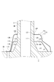
- FIG. 3 is a partially enlarged view of FIG. 2.
- (A) And (b) is a figure for demonstrating Helmholtz resonance.
- a rotary compressor 1 shown in FIG. 1 sucks gas refrigerant in an accumulator (gas-liquid separator) (not shown) through pipes 8 and 9 and compresses it by a compression mechanism 4.
- the compressor 1 and the accumulator constitute a refrigeration cycle apparatus such as an air conditioner or a refrigerator, and are connected to a refrigerant circuit (not shown) through which the refrigerant circulates.
- the compressor 1 is driven by a motor 2 as a power source, a rotating shaft 3 (crankshaft) rotated by a rotating driving force output from the motor 2, and a rotating driving force transmitted through the rotating shaft 3.
- a rotary compression mechanism 4 mufflers 10 and 20 arranged around the rotation shaft 3, and a housing 5. The mufflers 10 and 20 suppress noise caused by the pulsation of the refrigerant compressed by the compression mechanism 4.
- the housing 5 houses the motor 2, the rotating shaft 3, the compression mechanism 4, and the mufflers 10 and 20, and is formed in a cylindrical shape.
- the motor 2 includes a stator 2A that is fixed to the inner peripheral portion of the housing 5, and a rotor 2B that is disposed inside the stator 2A.
- the rotor 2B rotates relative to the stator 2A by energizing a coil 2C provided on the stator 2A.
- the rotating shaft 3 is coupled to the rotor 2B and protrudes downward from the rotor 2B.
- the upper crankpin 3B is eccentric with respect to the axis of the main shaft 3A.
- an eccentric lower crankpin 3C is eccentric with respect to the axis of the rotary shaft 3 in a direction opposite to the upper crankpin 3B (180 °).
- the upper crank pin 3 ⁇ / b> B is disposed in the upper cylinder 412 of the compression mechanism 4
- the lower crank pin 3 ⁇ / b> C is disposed in the lower cylinder 422 of the compression mechanism 4.
- the compression mechanism 4 (FIG. 1) will be described.
- the so-called twin rotary type compression mechanism 4 includes an upper compression mechanism 41, a lower compression mechanism 42, a partition plate 4A, and an upper bearing 6 and a lower bearing 7 that rotatably support the rotary shaft 3.
- the partition plate 4 ⁇ / b> A partitions the inside of the cylinder 412 of the upper compression mechanism 41 and the inside of the cylinder 422 of the lower compression mechanism 42.
- the upper compression mechanism 41 includes an upper piston rotor 411 provided on the upper crankpin 3B, an upper cylinder 412 in which the upper piston rotor 411 is disposed, and an upper muffler 10 disposed around the axis of the main shaft portion 3A.
- the upper piston rotor 411 is fitted to the outer peripheral portion of the upper crankpin 3 ⁇ / b> B, and is turned in the upper cylinder 412 as the rotary shaft 3 rotates. The refrigerant is sucked into the upper cylinder 412 through the pipe 8.
- the upper bearing 6 has an abutting portion 6A that abuts against the upper end surface of the upper cylinder 412 and a cylindrical bearing portion that protrudes upward from the abutting portion 6A and is positioned around the axis of the rotary shaft 3 (main shaft portion 3A). 6B.
- the abutting portion 6 ⁇ / b> A is fixed to the inner peripheral portion of the housing 5.
- An upper cylinder 412, an upper muffler 10, a lower cylinder 422, and a lower muffler 20 are integrally assembled to the upper bearing 6 with bolts 113.
- the refrigerant sucked into the upper cylinder 412 is compressed in a space ahead in the rotational direction with respect to a blade (not shown) pressed against the outer peripheral portion of the rotating upper piston rotor 411.
- the compressed refrigerant is discharged into the upper muffler 10 through the discharge port 6P (FIG. 2) formed in the abutting portion 6A of the upper bearing 6, and further from the upper muffler 10 to the motor 2 in the housing 5. Is also discharged into the space below.
- the lower compression mechanism 42 (FIG. 1) includes a lower piston rotor 421 provided in the lower crankpin 3C, a lower cylinder 422 in which the lower piston rotor 421 is disposed, and the axis of the main shaft portion 3A. And a lower muffler 20 disposed in the middle. A gas refrigerant is sucked into the lower cylinder 422 through the pipe 9.
- the lower bearing 7 has an abutting portion 7A that is abutted against the lower end surface of the lower cylinder 422, and a cylindrical bearing portion that projects downward from the abutting portion 7A and is located around the axis of the rotary shaft 3 (main shaft portion 3A). 7B.
- the refrigerant sucked into the lower cylinder 422 is compressed as the lower piston rotor 421 turns.
- the compressed refrigerant is discharged into the lower muffler 20 through the discharge port (not shown) formed in the abutting portion 7A of the lower bearing 7 and into the inner space of the housing 5, and further, the abutting portion of the upper bearing 6 It passes through a notch 61A formed in 6A and an opening (not shown), and is discharged into a space below the motor 2 in the housing 5.
- the refrigerant compressed by the upper compression mechanism 41 and the lower compression mechanism 42 is discharged into a space below the motor 2 in the housing 5.
- the refrigerant flows into a space above the motor 2 through a notch provided in the stator 2A and the rotor 2B, and is discharged to a refrigerant circuit through a discharge pipe 5A provided in the upper part of the housing 5.
- the upper compression mechanism 41 and the lower compression mechanism 42 each discharge refrigerant with pressure fluctuation (pulsation) from the discharge port according to the turning cycle of the piston rotors 411 and 421.
- the pulsations of the compressed refrigerant ejected to the mufflers 10 and 20 through the discharge ports by the upper compression mechanism 41 and the lower compression mechanism 42 are reduced in the mufflers 10 and 20, respectively.
- the compressor 1 of this embodiment is characterized by the structure of the upper muffler 10.
- the muffler 10 includes a muffler body 11 that forms a space 110 between the upper bearing 6 and the abutting portion 6A, and a cover 12 that forms a cavity 120 between the outer periphery 11S of the muffler body 11.
- the muffler body 11 and the cover 12 are each formed from a metal material such as an aluminum alloy, for example, by deep drawing.
- the muffler body 11 receives the compressed refrigerant compressed in the upper cylinder 412 (FIG. 1) and ejected from the discharge port 6P in the inner space 110, and reduces the pulsation of the compressed refrigerant. Since the space inside the muffler main body 11 acts as a resistance corresponding to the space volume for the refrigerant jetted into the muffler main body 11, the pulsation of the refrigerant is attenuated by the muffler main body 11.
- the muffler main body 11 is arranged around the axis of the rotary shaft 3.
- a bearing 6B that supports the rotary shaft 3 is passed through an opening formed in the center of the flat surface of the muffler body 11.
- the peripheral portion of the opening corresponds to the inner peripheral end 111 of the muffler main body 11.
- the muffler body 11 extends from the inner peripheral end 111 to the outside in the radial direction of the rotating shaft 3 with a predetermined diameter, and is formed in a substantially circular shape in plan view.
- the radially outer ends of the muffler body 11 are fastened to the upper bearing 6 by bolts 113 at a plurality of locations in the circumferential direction.
- the dimensions and volume of the muffler body 11 can be determined as appropriate so as to match the audible frequency component of the pulsation of the compressed refrigerant. The same applies to the cover 12.
- the muffler main body 11 is disposed on the abutting portion 6A, with a portion 11A extending radially outward from the inner peripheral end 111 positioned above the abutting portion 6A, and descending from the portion 11A toward the abutting portion 6A. 11B.
- the refrigerant ejected from the discharge port 6P is mainly sprayed onto the portion 11A.
- the shapes of the portions 11A and 11B are slightly different from other places.
- the muffler body 11 is not limited to the one shown in FIG. 2 and can be formed in an appropriate shape.
- the muffler body 11 may be formed in a dome shape. The same applies to the cover 12.
- a plurality of openings 11H are formed separately from the discharge port 11P and the discharge port 11P.
- the discharge port 11P allows the refrigerant to pass from the inside of the muffler main body 11 into the cavity 120.
- the discharge port 11P penetrates the portion 11A of the muffler main body 11 in the plate thickness direction.
- a plurality of discharge ports are formed at intervals in the circumferential direction of the muffler body 11. There is no particular restriction on the position of the discharge port 11P, but the phase angle of the discharge port 6P is different from that of the discharge port 6P so that the compressed refrigerant discharged from the discharge port 6P is not discharged from the muffler body 11 as it is.
- the discharge port 11P is formed at a position away from the discharge port 6P. As described later, this leads to a sufficient sound absorption effect utilizing Helmholtz resonance by introducing a refrigerant into each of the large number of openings 11H.
- the number of discharge ports 11P, the opening area of each discharge port 11P, and the total opening area of the plurality of discharge ports 11P are determined in consideration of the balance between the pressure loss for reducing pulsation and the performance of the compressor 1 and the like. It has been.
- the discharge port 12P of the cover 12 can also be formed in an annular shape around the axis of the rotary shaft 3 (around the axis of the bearing portion 6B of the upper bearing 6).
- Each of the plurality of openings 11H penetrates the muffler main body 11 in the plate thickness direction.
- the opening 11H is formed in the portion 11A.
- the opening 11H can be formed in the portion 11B or in both the portions 11A and 11B.
- the cross-sectional area (opening area) of the opening 11H is very small compared to the cross-sectional area of the discharge port 11P.
- the sectional area of the opening 11H is, for example, about 1/500 to 1/100 of the sectional area of the discharge port 11P.
- a large number of minute openings 11H are formed in the muffler main body 11 in order to enhance the pulsation reduction effect by the openings 11H and the cavities 120.
- the opening 11H can be formed as a circular round hole as shown in FIG. 4A.
- the opening 11H is not limited to this, and the opening 11H is appropriately configured as long as the inside and outside of the muffler main body 11 communicate with each other. Can do.
- a large number of openings 11H are formed over the entire surface of the muffler body 11.
- the cover 12 receives the refrigerant from the space 110 in the muffler body 11 into the cavity 120 between the cover 12 and discharges it from the discharge port 12P. Similar to the above-described muffler body 11, the cover 12 is arranged around the axis of the rotary shaft 3, and the bearing portion 6 ⁇ / b> B is passed through an opening formed in the center of the plane of the cover 12. An inner peripheral edge 121 (periphery edge of the opening) of the cover 12 is slightly raised along the axial direction. An annular gap between the inner peripheral end 121 and the bearing portion 6B is a discharge port 12P.
- the discharge port 12P may be formed at a position away from the discharge port 11P so that the refrigerant discharged from the discharge port 11P of the muffler main body 11 into the cover 12 does not go out of the cover 12 as it is. preferable.
- the discharge port 12P may be formed so as to penetrate the cover 12 in the plate thickness direction instead of around the axis of the bearing portion 6B.
- the cover 12 covers the outer peripheral portion 11 ⁇ / b> S of the muffler main body 11 and is fastened to the upper bearing 6 together with the muffler main body 11 by bolts 113.
- the inner peripheral end 121 of the cover 12 is located farther in the axial direction from the abutting portion 6 ⁇ / b> A of the upper bearing 6 than the inner peripheral end 111 of the muffler body 11.
- the cover 12 includes a portion 12A facing the portion 11A of the muffler main body 11, and a portion 12B descending from the portion 12A.
- the cover 12 of this embodiment covers the entire muffler main body 11, but the cover 12 may cover at least a part of the muffler main body 11 as long as a cavity 120 is formed between the cover 12 and the muffler main body 11. That's fine.
- the inner peripheral end 121 may face the outer peripheral portion of the rotating shaft 3 instead of the bearing portion 6B. In that case, the discharge port 12 ⁇ / b> P is formed between the inner peripheral end 121 and the outer peripheral portion of the rotating shaft 3.
- the lower muffler 20 (FIG. 1) is configured in substantially the same shape as the upper muffler 10, and is arranged around the axis of the lower bearing 7 so as to be reversed in the vertical direction with respect to the upper muffler 10. Unlike the upper muffler 10, the lower muffler 20 does not include a cover and is formed of a single member. However, like the upper muffler 10, the lower muffler 20 may be configured to include a muffler body and a cover. it can.
- the pulsation reduction effect by the upper muffler 10 will be described.
- the refrigerant compressed by the compression mechanism 41 is ejected into the space 110 and discharged from the discharge port 11P to the cavity 120.
- the ink is discharged into the inside, and further, discharged from the cavity 120 to the outside of the cover 12 through the discharge port 12P.
- the refrigerant sequentially passes through the inside of the muffler main body 11 and the inside of the cover 12, thereby reducing the pulsation of the refrigerant. That is, the muffler 10 including the muffler body 11 and the cover 12 functions as a two-stage muffler that reduces pulsation over two stages.
- the muffler 10 of the present embodiment achieves further pulsation reduction by establishing Helmholtz resonance by the opening 11H of the muffler main body 11 and the cavity 120 while maintaining the performance of reducing pulsation as a two-stage muffler.
- the opening 11H and the cavity 120 constitute a Helmholtz resonator.
- the Helmholtz resonance is caused by a certain frequency accompanying the surrounding air when the air mass 15 (air column) existing inside the opening 11H leading to the cavity 120 moves in the direction of the hole axis. Resonates at.
- the cavity 120 can be regarded as a spring provided in the air mass 15.
- the cross-sectional area S (transverse area) of the opening 11H, the plate thickness L of the muffler main body 11, and the volume V of the cavity 120 are determined to be in an appropriate relationship with each other.
- the basic formula of Helmholtz resonance is shown below. f is the natural frequency (natural frequency) of the air mass 15, and C is the speed of sound.
- LS which is the volume inside the opening 11H
- the hole diameter of the opening 11H is, for example, about 0.15 mm
- the plate thickness L is, for example, about 1.5 mm. Since each opening 11H is very small, the total LS of the plurality of openings 11H is also very small compared to the volume V of the cavity 120.
- the cross-sectional area of the opening 11H is smaller than that of the discharge port 11P and the discharge port 12P, the refrigerant received in the wide space 110 is discharged from the narrow discharge port 11P and also received in the cavity 120. Thus, it does not affect the main (mainstream) refrigerant flow involved in the basic pulsation reduction mechanism of the muffler 10 that discharges from the discharge port 12P.
- the cross-sectional area S and the plate thickness L can be determined in consideration of an appropriate frequency f to be reduced.
- an appropriate frequency f to be reduced For example, when the natural frequency (resonance frequency) of the air mass 15 is 250 Hz, the hole diameter of the opening 11H is set to 0.15 mm, the plate thickness of the muffler body 11 is set to 1.5 mm, and the volume V of the cavity 120 is set to 200 mm 3 . be able to.
- the hole diameter of the opening 11H needs to be sufficiently small, and the total of the cross-sectional areas S of the plurality of openings 11H is 1% of the surface area of the muffler body 11. The upper limit.
- the pulsation of the refrigerant compressed by the upper compression mechanism 41 and the lower compression mechanism 42 can be sufficiently reduced by the mufflers 10 and 20.
- the muffler 10 it is possible to obtain the pulsation reduction effect based on Helmholtz resonance while maintaining the pulsation reduction effect of the two-stage muffler that repeatedly discharges the pulsation into the space.
- the movement of the air mass 15 inside the minute opening 11H does not affect the main flow in the muffler. Therefore, according to the present embodiment, it is possible to sufficiently reduce the pulsation of the refrigerant while suppressing the performance of the compressor 1 and to suppress noise due to the pressure fluctuation of the refrigerant.
- the muffler 10 can suppress the sound pressure from being emitted by the muffler 10 itself as a sound source by reducing the pulsation, the noise can be suppressed even if the thickness of the muffler body 11 and the cover 12 is thin. It becomes possible.
- the compression mechanism mounted on the compressor of the present invention is not limited to the twin rotary type compression mechanism 4, but may be a single rotary type compression mechanism having a pair of cylinders and piston rotors, and a muffler.
- the compressor of the present invention is not limited to a rotary compressor, and may be a scroll compressor.
- the configuration of the present invention may be applied to a muffler (also referred to as a discharge cover) that receives the compressed refrigerant discharged from the scroll compression mechanism.
- the discharge cover may include a muffler main body and a cover, and the minute opening 11H may be formed in the muffler main body.
- a power source of the compressor of the present invention for example, an engine or the like other than the motor is allowed.
Abstract
Provided is a compressor in which an appropriate pulsation frequency component of a fluid can be sufficiently reduced by a muffler while the performance of the compressor is ensured. A compressor 1 is provided with a compression mechanism 4 that compresses a refrigerant, and a muffler 10 that reduces pulsation of the refrigerant compressed by the compression mechanism 4. The muffler 10 is provided with: a muffler body 11 that takes refrigerant into the interior thereof from the compression mechanism; and a cover 12 that forms a cavity 120 with an outer periphery 11S of the muffler body 11, the cover 12 discharging the refrigerant taken in from the interior of the muffler body 11. A plurality of openings 11H passing through in the plate thickness direction are formed in the muffler body 11, separately from a discharge port 11P through which refrigerant passes into the cavity 120 from the interior of the muffler body 11. Due to the relationship between the speed of sound C, the cross-sectional area S of each of the openings 11H, the plate thickness L, and the volume V of the cavity 120, Helmholtz resonance arises in air masses 15 located inside the openings 11H leading into the cavity 120, whereby sound is absorbed.
Description
本発明は、圧縮された流体の圧力変動(脈動)を低減するマフラが備えられた圧縮機に関する。
The present invention relates to a compressor provided with a muffler for reducing pressure fluctuation (pulsation) of a compressed fluid.
空気調和機等を構成するロータリー圧縮機は、ピストンロータの回転によりシリンダ内で冷媒を圧縮する圧縮機構と、圧縮冷媒の圧力変動に起因する騒音を抑制するマフラとを備えている。
ロータリー圧縮機のマフラとして、第1マフラと第2マフラとからなる二段マフラも採用されている(例えば、特許文献1)。圧縮された冷媒は、シリンダが固定された軸受の吐出ポートから、第1マフラの内側に吐出され、さらに、第1マフラの吐出口を通じて、第1マフラ内から第2マフラ内へと吐出される。第1マフラ内の空間、および第2マフラ内の空間は、圧縮冷媒にとって、空間体積に応じた抵抗として働くので、第1マフラおよび第2マフラを順次通過することで、冷媒の脈動が低減される。 A rotary compressor that constitutes an air conditioner or the like includes a compression mechanism that compresses refrigerant in a cylinder by rotation of a piston rotor, and a muffler that suppresses noise caused by pressure fluctuations of the compressed refrigerant.
As a muffler for a rotary compressor, a two-stage muffler composed of a first muffler and a second muffler is also employed (for example, Patent Document 1). The compressed refrigerant is discharged to the inside of the first muffler from the discharge port of the bearing to which the cylinder is fixed, and is further discharged from the first muffler into the second muffler through the discharge port of the first muffler. . Since the space in the first muffler and the space in the second muffler act as resistance corresponding to the space volume for the compressed refrigerant, the pulsation of the refrigerant is reduced by sequentially passing through the first muffler and the second muffler. The
圧縮機構に通常のマフラや二段マフラが設置されていても、必ずしも、圧縮冷媒の脈動の周波数成分に対して、十分な脈動低減効果を得ることができない場合がある。
特に、二段マフラの場合、重量やコストの制約から、マフラの板厚を十分に取って剛性を向上させることが難しいので、冷媒の脈動の圧力波がマフラの外部へと放射され易い。
マフラの吐出口の開口面積を絞ると、マフラから吐出される冷媒に圧力損失を与え、脈動を低減することができるが、圧縮機の性能低下に繋がってしまう。特に二段マフラの場合、圧力損失が大きいので、吐出口の開口面積を絞ることには限界がある。 Even if a normal muffler or a two-stage muffler is installed in the compression mechanism, a sufficient pulsation reduction effect may not always be obtained for the frequency component of the pulsation of the compressed refrigerant.
In particular, in the case of a two-stage muffler, it is difficult to improve the rigidity by sufficiently taking the thickness of the muffler due to restrictions on weight and cost, so that the pressure wave of the pulsation of the refrigerant is likely to be radiated to the outside of the muffler.
If the opening area of the outlet of the muffler is reduced, pressure loss can be given to the refrigerant discharged from the muffler and pulsation can be reduced, but this leads to a reduction in the performance of the compressor. In particular, in the case of a two-stage muffler, since the pressure loss is large, there is a limit to reducing the opening area of the discharge port.
以上より、本発明は、圧縮機の性能を確保しながら、マフラにより、流体の適宜な脈動周波数成分を十分に低減させることが可能な圧縮機を提供することを目的とする。
In view of the above, an object of the present invention is to provide a compressor capable of sufficiently reducing an appropriate pulsation frequency component of a fluid with a muffler while ensuring the performance of the compressor.
本発明の圧縮機は、流体を圧縮する圧縮機構と、圧縮機構により圧縮された流体の脈動を低減するマフラと、を備え、マフラは、圧縮機構から流体を内側に受け入れるマフラ本体と、マフラ本体の外周部との間に空洞を形成し、マフラ本体の内側から受け入れた流体を吐出するカバーと、を備え、マフラ本体には、マフラ本体の内側から空洞内へと流体が通過する吐出口とは別に、板厚方向に貫通する複数の開口が形成されており、音速C、開口の各々の断面積S、板厚L、および空洞の体積Vの関係より、空洞に通じる開口の内部に存在する空気塊に関してヘルムホルツ共鳴が成立することで、吸音されることを特徴とする。
A compressor according to the present invention includes a compression mechanism that compresses a fluid, and a muffler that reduces pulsation of the fluid compressed by the compression mechanism. The muffler includes a muffler body that receives fluid from the compression mechanism inside, and the muffler body. A cover that discharges fluid received from the inside of the muffler body, and a discharge port through which the fluid passes from the inside of the muffler body into the cavity. Separately, a plurality of openings penetrating in the plate thickness direction are formed, and exist in the openings leading to the cavities based on the relationship between the sound velocity C, the sectional area S of each of the openings, the plate thickness L, and the volume V of the cavities. Sound absorption is performed when Helmholtz resonance is established with respect to the air mass.
本発明の圧縮機において、圧縮機構は、回転軸に設けられるピストンロータおよびピストンロータが配置されるシリンダを有し、マフラ本体およびカバーは、回転軸の軸周りに配置されていることが好ましい。
In the compressor according to the present invention, it is preferable that the compression mechanism has a piston rotor provided on the rotating shaft and a cylinder in which the piston rotor is arranged, and the muffler body and the cover are arranged around the axis of the rotating shaft.
本発明によれば、詳しくは後述するように、空間内への脈動の吐出を繰り返す二段マフラによる脈動低減効果を維持しながら、ヘルムホルツ共鳴に基づく脈動低減効果をも得ることができる。ヘルムホルツ共鳴を起こすマフラ本体の微小な開口内部の空気塊の運動は、マフラ内の主流には影響を与えないので、圧縮機の性能を確保しながら、流体の脈動を十分に低減させて吸音を図り、流体の圧力変動に起因する騒音を抑制することができる。
本発明によれば、脈動低減により、マフラが音源となって音圧が放射されることを抑えることができるので、マフラ本体やカバーの板厚が薄いとしても、騒音を抑えることが可能となる。 According to the present invention, as will be described in detail later, it is possible to obtain a pulsation reduction effect based on Helmholtz resonance while maintaining a pulsation reduction effect by a two-stage muffler that repeatedly discharges pulsation into the space. The motion of the air mass inside the small opening of the muffler body that causes Helmholtz resonance does not affect the main flow in the muffler, so the pulsation of the fluid is sufficiently reduced to absorb sound while ensuring the performance of the compressor. In other words, noise caused by fluid pressure fluctuations can be suppressed.
According to the present invention, it is possible to suppress the sound pressure from being emitted by the muffler as a sound source by reducing the pulsation, so that it is possible to suppress the noise even if the thickness of the muffler main body and the cover is thin. .
以下、添付図面を参照しながら、本発明の実施形態について説明する。
図1に示すロータリー式圧縮機1は、図示しないアキュムレータ(気液分離器)内のガス冷媒を配管8,9を通じて吸入し、圧縮機構4により圧縮する。
圧縮機1およびアキュムレータは、空気調和機、冷凍機等の冷凍サイクル装置を構成しており、冷媒が循環する図示しない冷媒回路に接続されている。 Hereinafter, embodiments of the present invention will be described with reference to the accompanying drawings.
Arotary compressor 1 shown in FIG. 1 sucks gas refrigerant in an accumulator (gas-liquid separator) (not shown) through pipes 8 and 9 and compresses it by a compression mechanism 4.
Thecompressor 1 and the accumulator constitute a refrigeration cycle apparatus such as an air conditioner or a refrigerator, and are connected to a refrigerant circuit (not shown) through which the refrigerant circulates.
図1に示すロータリー式圧縮機1は、図示しないアキュムレータ(気液分離器)内のガス冷媒を配管8,9を通じて吸入し、圧縮機構4により圧縮する。
圧縮機1およびアキュムレータは、空気調和機、冷凍機等の冷凍サイクル装置を構成しており、冷媒が循環する図示しない冷媒回路に接続されている。 Hereinafter, embodiments of the present invention will be described with reference to the accompanying drawings.
A
The
圧縮機1は、動力源であるモータ2と、モータ2から出力される回転駆動力により回転される回転軸3(クランクシャフト)と、回転軸3を介して伝達される回転駆動力により駆動されるロータリー式の圧縮機構4と、回転軸3の軸周りに配置されるマフラ10,20と、ハウジング5とを備えている。
マフラ10,20は、圧縮機構4により圧縮された冷媒の脈動に起因する騒音を抑制する。 Thecompressor 1 is driven by a motor 2 as a power source, a rotating shaft 3 (crankshaft) rotated by a rotating driving force output from the motor 2, and a rotating driving force transmitted through the rotating shaft 3. A rotary compression mechanism 4, mufflers 10 and 20 arranged around the rotation shaft 3, and a housing 5.
The mufflers 10 and 20 suppress noise caused by the pulsation of the refrigerant compressed by the compression mechanism 4.
マフラ10,20は、圧縮機構4により圧縮された冷媒の脈動に起因する騒音を抑制する。 The
The
ハウジング5は、モータ2、回転軸3、圧縮機構4、およびマフラ10,20を収容しており、円筒状に形成されている。
モータ2は、ハウジング5の内周部に固定されるステータ2Aと、ステータ2Aの内側に配置されるロータ2Bとを備えている。ロータ2Bは、ステータ2Aに設けられたコイル2Cへの通電によりステータ2Aに対して回転する。 Thehousing 5 houses the motor 2, the rotating shaft 3, the compression mechanism 4, and the mufflers 10 and 20, and is formed in a cylindrical shape.
Themotor 2 includes a stator 2A that is fixed to the inner peripheral portion of the housing 5, and a rotor 2B that is disposed inside the stator 2A. The rotor 2B rotates relative to the stator 2A by energizing a coil 2C provided on the stator 2A.
モータ2は、ハウジング5の内周部に固定されるステータ2Aと、ステータ2Aの内側に配置されるロータ2Bとを備えている。ロータ2Bは、ステータ2Aに設けられたコイル2Cへの通電によりステータ2Aに対して回転する。 The
The
回転軸3は、ロータ2Bに結合されてロータ2Bよりも下方に突出する主軸部3Aと、主軸部3Aの軸心に対して偏心した上部クランクピン3Bと、同じく主軸部3Aの軸心に対して偏心した下部クランクピン3Cとを備えている。下部クランクピン3Cは、回転軸3の軸心に対して、上部クランクピン3Bとは逆位相(180°)となる向きに偏心している。
上部クランクピン3Bは、圧縮機構4の上部シリンダ412内に配置され、下部クランクピン3Cは、圧縮機構4の下部シリンダ422内に配置されている。 The rotatingshaft 3 is coupled to the rotor 2B and protrudes downward from the rotor 2B. The upper crankpin 3B is eccentric with respect to the axis of the main shaft 3A. And an eccentric lower crankpin 3C. The lower crankpin 3C is eccentric with respect to the axis of the rotary shaft 3 in a direction opposite to the upper crankpin 3B (180 °).
Theupper crank pin 3 </ b> B is disposed in the upper cylinder 412 of the compression mechanism 4, and the lower crank pin 3 </ b> C is disposed in the lower cylinder 422 of the compression mechanism 4.
上部クランクピン3Bは、圧縮機構4の上部シリンダ412内に配置され、下部クランクピン3Cは、圧縮機構4の下部シリンダ422内に配置されている。 The rotating
The
圧縮機構4(図1)について説明する。
所謂ツインロータリー式である圧縮機構4は、上部圧縮機構41と、下部圧縮機構42と、仕切板4Aと、回転軸3を回転可能に支持する上部軸受6および下部軸受7とを備えている。
仕切板4Aは、上部圧縮機構41のシリンダ412の内部と下部圧縮機構42のシリンダ422の内部とを仕切っている。 The compression mechanism 4 (FIG. 1) will be described.
The so-called twin rotarytype compression mechanism 4 includes an upper compression mechanism 41, a lower compression mechanism 42, a partition plate 4A, and an upper bearing 6 and a lower bearing 7 that rotatably support the rotary shaft 3.
Thepartition plate 4 </ b> A partitions the inside of the cylinder 412 of the upper compression mechanism 41 and the inside of the cylinder 422 of the lower compression mechanism 42.
所謂ツインロータリー式である圧縮機構4は、上部圧縮機構41と、下部圧縮機構42と、仕切板4Aと、回転軸3を回転可能に支持する上部軸受6および下部軸受7とを備えている。
仕切板4Aは、上部圧縮機構41のシリンダ412の内部と下部圧縮機構42のシリンダ422の内部とを仕切っている。 The compression mechanism 4 (FIG. 1) will be described.
The so-called twin rotary
The
上部圧縮機構41は、上部クランクピン3Bに設けられる上部ピストンロータ411と、上部ピストンロータ411が配置される上部シリンダ412と、主軸部3Aの軸周りに配置される上部マフラ10とを含んで構成されている。
上部ピストンロータ411は、上部クランクピン3Bの外周部に嵌合され、回転軸3の回転に伴って上部シリンダ412内で旋回される。
上部シリンダ412内には、配管8を通じて冷媒が吸入される。 Theupper compression mechanism 41 includes an upper piston rotor 411 provided on the upper crankpin 3B, an upper cylinder 412 in which the upper piston rotor 411 is disposed, and an upper muffler 10 disposed around the axis of the main shaft portion 3A. Has been.
Theupper piston rotor 411 is fitted to the outer peripheral portion of the upper crankpin 3 </ b> B, and is turned in the upper cylinder 412 as the rotary shaft 3 rotates.
The refrigerant is sucked into theupper cylinder 412 through the pipe 8.
上部ピストンロータ411は、上部クランクピン3Bの外周部に嵌合され、回転軸3の回転に伴って上部シリンダ412内で旋回される。
上部シリンダ412内には、配管8を通じて冷媒が吸入される。 The
The
The refrigerant is sucked into the
上部軸受6は、上部シリンダ412の上端面に突き当てられる突当て部6Aと、突当て部6Aから上方へと突出し、回転軸3(主軸部3A)の軸周りに位置する円筒状の軸受部6Bとを有している。突当て部6Aは、ハウジング5の内周部に固定されている。
上部軸受6には、上部シリンダ412、上部マフラ10、下部シリンダ422、および下部マフラ20がボルト113により一体に組み付けられている。 Theupper bearing 6 has an abutting portion 6A that abuts against the upper end surface of the upper cylinder 412 and a cylindrical bearing portion that protrudes upward from the abutting portion 6A and is positioned around the axis of the rotary shaft 3 (main shaft portion 3A). 6B. The abutting portion 6 </ b> A is fixed to the inner peripheral portion of the housing 5.
Anupper cylinder 412, an upper muffler 10, a lower cylinder 422, and a lower muffler 20 are integrally assembled to the upper bearing 6 with bolts 113.
上部軸受6には、上部シリンダ412、上部マフラ10、下部シリンダ422、および下部マフラ20がボルト113により一体に組み付けられている。 The
An
上部シリンダ412内に吸入された冷媒は、旋回する上部ピストンロータ411の外周部に押圧される図示しないブレードよりも回転方向前方の空間にて圧縮される。圧縮された冷媒は、上部軸受6の突当て部6Aに形成された吐出ポート6P(図2)を通じて上部マフラ10内へと吐出され、さらに、上部マフラ10内から、ハウジング5内におけるモータ2よりも下方の空間へと吐出される。
The refrigerant sucked into the upper cylinder 412 is compressed in a space ahead in the rotational direction with respect to a blade (not shown) pressed against the outer peripheral portion of the rotating upper piston rotor 411. The compressed refrigerant is discharged into the upper muffler 10 through the discharge port 6P (FIG. 2) formed in the abutting portion 6A of the upper bearing 6, and further from the upper muffler 10 to the motor 2 in the housing 5. Is also discharged into the space below.
上部圧縮機構41と同様に、下部圧縮機構42(図1)は、下部クランクピン3Cに設けられる下部ピストンロータ421と、下部ピストンロータ421が配置される下部シリンダ422と、主軸部3Aの軸周りに配置される下部マフラ20とを含んで構成されている。
下部シリンダ422内には、配管9を通じてガス冷媒が吸入される。 Similar to theupper compression mechanism 41, the lower compression mechanism 42 (FIG. 1) includes a lower piston rotor 421 provided in the lower crankpin 3C, a lower cylinder 422 in which the lower piston rotor 421 is disposed, and the axis of the main shaft portion 3A. And a lower muffler 20 disposed in the middle.
A gas refrigerant is sucked into thelower cylinder 422 through the pipe 9.
下部シリンダ422内には、配管9を通じてガス冷媒が吸入される。 Similar to the
A gas refrigerant is sucked into the
下部軸受7は、下部シリンダ422の下端面に突き当てられる突当て部7Aと、突当て部7Aから下方へと突出し、回転軸3(主軸部3A)の軸周りに位置する円筒状の軸受部7Bとを有している。
The lower bearing 7 has an abutting portion 7A that is abutted against the lower end surface of the lower cylinder 422, and a cylindrical bearing portion that projects downward from the abutting portion 7A and is located around the axis of the rotary shaft 3 (main shaft portion 3A). 7B.
下部シリンダ422内に吸入された冷媒は、下部ピストンロータ421の旋回に伴って圧縮される。圧縮された冷媒は、下部軸受7の突当て部7Aに形成された図示しない吐出ポートを通じて下部マフラ20内へ、そして、ハウジング5の内部空間へと吐出され、さらに、上部軸受6の突当て部6Aに形成された切欠61Aや図示しない開口を通り抜け、ハウジング5内におけるモータ2よりも下方の空間へと吐出される。
The refrigerant sucked into the lower cylinder 422 is compressed as the lower piston rotor 421 turns. The compressed refrigerant is discharged into the lower muffler 20 through the discharge port (not shown) formed in the abutting portion 7A of the lower bearing 7 and into the inner space of the housing 5, and further, the abutting portion of the upper bearing 6 It passes through a notch 61A formed in 6A and an opening (not shown), and is discharged into a space below the motor 2 in the housing 5.
上述のように、ハウジング5内におけるモータ2よりも下方の空間に、上部圧縮機構41および下部圧縮機構42によりそれぞれ圧縮された冷媒が吐出される。その冷媒は、ステータ2Aやロータ2Bに設けられた切欠を通じてモータ2よりも上方の空間へと流れ、ハウジング5の上部に設けられた吐出管5Aを通じて冷媒回路へと吐出される。
As described above, the refrigerant compressed by the upper compression mechanism 41 and the lower compression mechanism 42 is discharged into a space below the motor 2 in the housing 5. The refrigerant flows into a space above the motor 2 through a notch provided in the stator 2A and the rotor 2B, and is discharged to a refrigerant circuit through a discharge pipe 5A provided in the upper part of the housing 5.
上部圧縮機構41および下部圧縮機構42はそれぞれ、ピストンロータ411,421の旋回周期に応じて、吐出ポートから圧力変動(脈動)を伴って冷媒を吐出する。上部圧縮機構41および下部圧縮機構42により吐出ポートを通じてマフラ10,20へとそれぞれ噴出した圧縮冷媒の脈動は、マフラ10,20内でそれぞれ低減される。
The upper compression mechanism 41 and the lower compression mechanism 42 each discharge refrigerant with pressure fluctuation (pulsation) from the discharge port according to the turning cycle of the piston rotors 411 and 421. The pulsations of the compressed refrigerant ejected to the mufflers 10 and 20 through the discharge ports by the upper compression mechanism 41 and the lower compression mechanism 42 are reduced in the mufflers 10 and 20, respectively.
本実施形態の圧縮機1は、上部マフラ10の構造に特徴を有する。
まず、図2および図3を参照し、上部マフラ10(以下、マフラ10)の構成を説明する。
マフラ10は、上部軸受6の突当て部6Aとの間に空間110を形成するマフラ本体11と、マフラ本体11の外周部11Sとの間に空洞120を形成するカバー12とを備えている。
マフラ本体11およびカバー12は、それぞれ、アルミニウム合金等の金属材料から、例えば、深絞り加工によって形成されている。 Thecompressor 1 of this embodiment is characterized by the structure of the upper muffler 10.
First, the configuration of the upper muffler 10 (hereinafter referred to as the muffler 10) will be described with reference to FIGS.
Themuffler 10 includes a muffler body 11 that forms a space 110 between the upper bearing 6 and the abutting portion 6A, and a cover 12 that forms a cavity 120 between the outer periphery 11S of the muffler body 11.
Themuffler body 11 and the cover 12 are each formed from a metal material such as an aluminum alloy, for example, by deep drawing.
まず、図2および図3を参照し、上部マフラ10(以下、マフラ10)の構成を説明する。
マフラ10は、上部軸受6の突当て部6Aとの間に空間110を形成するマフラ本体11と、マフラ本体11の外周部11Sとの間に空洞120を形成するカバー12とを備えている。
マフラ本体11およびカバー12は、それぞれ、アルミニウム合金等の金属材料から、例えば、深絞り加工によって形成されている。 The
First, the configuration of the upper muffler 10 (hereinafter referred to as the muffler 10) will be described with reference to FIGS.
The
The
マフラ本体11は、上部シリンダ412(図1)内で圧縮され吐出ポート6Pから噴出した圧縮冷媒を内側の空間110に受け入れ、圧縮冷媒の脈動を低減する。マフラ本体11の内側の空間は、マフラ本体11内に噴出された冷媒にとって、空間体積に応じた抵抗として働くので、マフラ本体11により冷媒の脈動が減衰する。
The muffler body 11 receives the compressed refrigerant compressed in the upper cylinder 412 (FIG. 1) and ejected from the discharge port 6P in the inner space 110, and reduces the pulsation of the compressed refrigerant. Since the space inside the muffler main body 11 acts as a resistance corresponding to the space volume for the refrigerant jetted into the muffler main body 11, the pulsation of the refrigerant is attenuated by the muffler main body 11.
マフラ本体11は、回転軸3の軸周りに配置されている。マフラ本体11の平面中央部に形成された開口に、回転軸3を支持している軸受部6Bが通される。その開口の周縁部が、マフラ本体11の内周端111に相当する。
マフラ本体11は、内周端111から回転軸3の径方向外側に所定の直径で延在しており、平面視略円形状に形成されている。マフラ本体11の径方向外側の端部は、周方向の複数の箇所で、ボルト113により上部軸受6に締結されている。 The mufflermain body 11 is arranged around the axis of the rotary shaft 3. A bearing 6B that supports the rotary shaft 3 is passed through an opening formed in the center of the flat surface of the muffler body 11. The peripheral portion of the opening corresponds to the inner peripheral end 111 of the muffler main body 11.
Themuffler body 11 extends from the inner peripheral end 111 to the outside in the radial direction of the rotating shaft 3 with a predetermined diameter, and is formed in a substantially circular shape in plan view. The radially outer ends of the muffler body 11 are fastened to the upper bearing 6 by bolts 113 at a plurality of locations in the circumferential direction.
マフラ本体11は、内周端111から回転軸3の径方向外側に所定の直径で延在しており、平面視略円形状に形成されている。マフラ本体11の径方向外側の端部は、周方向の複数の箇所で、ボルト113により上部軸受6に締結されている。 The muffler
The
マフラ本体11の寸法や体積は、圧縮冷媒の脈動の可聴周波数成分に適合するように適宜に定めることができる。これは、カバー12も同様である。
The dimensions and volume of the muffler body 11 can be determined as appropriate so as to match the audible frequency component of the pulsation of the compressed refrigerant. The same applies to the cover 12.
マフラ本体11は、突当て部6Aよりも上方に位置する内周端111から径方向外側に延在する部分11Aと、部分11Aから突当て部6Aに向けて下り、突当て部6Aに配置される部分11Bとを備えている。吐出ポート6Pから噴出した冷媒は、主として、部分11Aに吹き付けられる。
The muffler main body 11 is disposed on the abutting portion 6A, with a portion 11A extending radially outward from the inner peripheral end 111 positioned above the abutting portion 6A, and descending from the portion 11A toward the abutting portion 6A. 11B. The refrigerant ejected from the discharge port 6P is mainly sprayed onto the portion 11A.
マフラ本体11がボルト113により締結される箇所では、部分11A,11Bの形状が他の箇所とは若干異なっている。マフラ本体11は、図2に示したものに限られることなく、適宜な形状に形成することができる。例えば、マフラ本体11がドーム状に形成されることも許容される。以上は、カバー12についても同様である。
In the place where the muffler main body 11 is fastened by the bolt 113, the shapes of the portions 11A and 11B are slightly different from other places. The muffler body 11 is not limited to the one shown in FIG. 2 and can be formed in an appropriate shape. For example, the muffler body 11 may be formed in a dome shape. The same applies to the cover 12.
マフラ本体11には、吐出口11Pと、吐出口11Pとは別に、複数の開口11Hが形成されている。
吐出口11Pは、マフラ本体11の内側から空洞120内へと冷媒を通過させる。
吐出口11Pは、マフラ本体11の部分11Aを板厚方向に貫通している。また、マフラ本体11の周方向に間隔をおいて複数の吐出口が形成されている。
吐出口11Pの位置には特に制約がないが、吐出ポート6Pから噴出する圧縮冷媒がそのままマフラ本体11内から吐出されてしまわないように、吐出ポート6Pとは位相角が異なる位置に、かつ、吐出ポート6Pから離れている位置に吐出口11Pが形成されていることが好ましい。このことが、後述するように、多数の開口11Hのそれぞれに冷媒を導入し、ヘルムホルツ共振を利用した吸音効果を十分に得ることにも繋がる。
吐出口11Pの数や、各吐出口11Pの開口面積および複数の吐出口11Pの合計の開口面積は、脈動低減のための圧力損失と、圧縮機1の性能とのバランス等を考慮して定められている。これは、カバー12の吐出口12Pも同様である。
なお、吐出口11Pを回転軸3の軸周り(上部軸受6の軸受部6Bの軸周り)に沿って円環状に形成することもできる。 In themuffler body 11, a plurality of openings 11H are formed separately from the discharge port 11P and the discharge port 11P.
Thedischarge port 11P allows the refrigerant to pass from the inside of the muffler main body 11 into the cavity 120.
Thedischarge port 11P penetrates the portion 11A of the muffler main body 11 in the plate thickness direction. Further, a plurality of discharge ports are formed at intervals in the circumferential direction of the muffler body 11.
There is no particular restriction on the position of thedischarge port 11P, but the phase angle of the discharge port 6P is different from that of the discharge port 6P so that the compressed refrigerant discharged from the discharge port 6P is not discharged from the muffler body 11 as it is. It is preferable that the discharge port 11P is formed at a position away from the discharge port 6P. As described later, this leads to a sufficient sound absorption effect utilizing Helmholtz resonance by introducing a refrigerant into each of the large number of openings 11H.
The number ofdischarge ports 11P, the opening area of each discharge port 11P, and the total opening area of the plurality of discharge ports 11P are determined in consideration of the balance between the pressure loss for reducing pulsation and the performance of the compressor 1 and the like. It has been. The same applies to the discharge port 12P of the cover 12.
In addition, thedischarge port 11P can also be formed in an annular shape around the axis of the rotary shaft 3 (around the axis of the bearing portion 6B of the upper bearing 6).
吐出口11Pは、マフラ本体11の内側から空洞120内へと冷媒を通過させる。
吐出口11Pは、マフラ本体11の部分11Aを板厚方向に貫通している。また、マフラ本体11の周方向に間隔をおいて複数の吐出口が形成されている。
吐出口11Pの位置には特に制約がないが、吐出ポート6Pから噴出する圧縮冷媒がそのままマフラ本体11内から吐出されてしまわないように、吐出ポート6Pとは位相角が異なる位置に、かつ、吐出ポート6Pから離れている位置に吐出口11Pが形成されていることが好ましい。このことが、後述するように、多数の開口11Hのそれぞれに冷媒を導入し、ヘルムホルツ共振を利用した吸音効果を十分に得ることにも繋がる。
吐出口11Pの数や、各吐出口11Pの開口面積および複数の吐出口11Pの合計の開口面積は、脈動低減のための圧力損失と、圧縮機1の性能とのバランス等を考慮して定められている。これは、カバー12の吐出口12Pも同様である。
なお、吐出口11Pを回転軸3の軸周り(上部軸受6の軸受部6Bの軸周り)に沿って円環状に形成することもできる。 In the
The
The
There is no particular restriction on the position of the
The number of
In addition, the
複数の開口11Hは、いずれも、マフラ本体11を板厚方向に貫通している。図2に示す例では、開口11Hが部分11Aに形成されているが、開口11Hを部分11Bに形成したり、部分11A、11Bの両方に形成したりすることもできる。
開口11Hの断面積(開口面積)は、吐出口11Pの断面積と比べて非常に小さい。開口11Hの断面積は、例えば、吐出口11Pの断面積の1/500~1/100)程度である。後述するように、開口11Hと空洞120とによる脈動低減効果を高めるため、微小な開口11Hがマフラ本体11に多数形成されていることが好ましい。
開口11Hは、図4(a)に示すように、円形の丸孔として形成することができるが、これに限らず、マフラ本体11の内外を連通する限りにおいて、開口11Hを適宜に構成することができる。
脈動低減効果を高めるため、マフラ本体11の全面に亘って多数の開口11Hが形成されることが好ましい。 Each of the plurality ofopenings 11H penetrates the muffler main body 11 in the plate thickness direction. In the example shown in FIG. 2, the opening 11H is formed in the portion 11A. However, the opening 11H can be formed in the portion 11B or in both the portions 11A and 11B.
The cross-sectional area (opening area) of theopening 11H is very small compared to the cross-sectional area of the discharge port 11P. The sectional area of the opening 11H is, for example, about 1/500 to 1/100 of the sectional area of the discharge port 11P. As will be described later, it is preferable that a large number of minute openings 11H are formed in the muffler main body 11 in order to enhance the pulsation reduction effect by the openings 11H and the cavities 120.
Theopening 11H can be formed as a circular round hole as shown in FIG. 4A. However, the opening 11H is not limited to this, and the opening 11H is appropriately configured as long as the inside and outside of the muffler main body 11 communicate with each other. Can do.
In order to enhance the pulsation reducing effect, it is preferable that a large number ofopenings 11H are formed over the entire surface of the muffler body 11.
開口11Hの断面積(開口面積)は、吐出口11Pの断面積と比べて非常に小さい。開口11Hの断面積は、例えば、吐出口11Pの断面積の1/500~1/100)程度である。後述するように、開口11Hと空洞120とによる脈動低減効果を高めるため、微小な開口11Hがマフラ本体11に多数形成されていることが好ましい。
開口11Hは、図4(a)に示すように、円形の丸孔として形成することができるが、これに限らず、マフラ本体11の内外を連通する限りにおいて、開口11Hを適宜に構成することができる。
脈動低減効果を高めるため、マフラ本体11の全面に亘って多数の開口11Hが形成されることが好ましい。 Each of the plurality of
The cross-sectional area (opening area) of the
The
In order to enhance the pulsation reducing effect, it is preferable that a large number of
カバー12(図2および図3)は、マフラ本体11との間の空洞120にマフラ本体11内の空間110から冷媒を受け入れ、吐出口12Pから吐出する。
カバー12は、上述のマフラ本体11と同様に、回転軸3の軸周りに配置されており、カバー12の平面中央部に形成された開口に、軸受部6Bが通される。
カバー12の内周端121(開口の周縁部)は、軸方向に沿って少し立ち上がっている。この内周端121と、軸受部6Bとの間の円環状の隙間が吐出口12Pとなっている。
吐出口12Pは、マフラ本体11の吐出口11Pからカバー12内へと吐出された冷媒がそのままカバー12の外部へと出ていかないように、吐出口11Pから離れた位置に形成されていることが好ましい。吐出口12Pは、軸受部6Bの軸周りにではなく、カバー12を板厚方向に貫通するように形成されていてもよい。 The cover 12 (FIGS. 2 and 3) receives the refrigerant from thespace 110 in the muffler body 11 into the cavity 120 between the cover 12 and discharges it from the discharge port 12P.
Similar to the above-describedmuffler body 11, the cover 12 is arranged around the axis of the rotary shaft 3, and the bearing portion 6 </ b> B is passed through an opening formed in the center of the plane of the cover 12.
An inner peripheral edge 121 (periphery edge of the opening) of thecover 12 is slightly raised along the axial direction. An annular gap between the inner peripheral end 121 and the bearing portion 6B is a discharge port 12P.
Thedischarge port 12P may be formed at a position away from the discharge port 11P so that the refrigerant discharged from the discharge port 11P of the muffler main body 11 into the cover 12 does not go out of the cover 12 as it is. preferable. The discharge port 12P may be formed so as to penetrate the cover 12 in the plate thickness direction instead of around the axis of the bearing portion 6B.
カバー12は、上述のマフラ本体11と同様に、回転軸3の軸周りに配置されており、カバー12の平面中央部に形成された開口に、軸受部6Bが通される。
カバー12の内周端121(開口の周縁部)は、軸方向に沿って少し立ち上がっている。この内周端121と、軸受部6Bとの間の円環状の隙間が吐出口12Pとなっている。
吐出口12Pは、マフラ本体11の吐出口11Pからカバー12内へと吐出された冷媒がそのままカバー12の外部へと出ていかないように、吐出口11Pから離れた位置に形成されていることが好ましい。吐出口12Pは、軸受部6Bの軸周りにではなく、カバー12を板厚方向に貫通するように形成されていてもよい。 The cover 12 (FIGS. 2 and 3) receives the refrigerant from the
Similar to the above-described
An inner peripheral edge 121 (periphery edge of the opening) of the
The
カバー12は、マフラ本体11の外周部11Sを覆っており、マフラ本体11と共に、ボルト113により上部軸受6に締結されている。
カバー12の内周端121は、マフラ本体11の内周端111よりも上部軸受6の突当て部6Aから軸方向に離れた位置にある。カバー12は、マフラ本体11の部分11Aに対向する部分12Aと、部分12Aから下る部分12Bとを備えている。
本実施形態のカバー12は、マフラ本体11の全体を取り囲むように覆っているが、マフラ本体11との間に空洞120を形成する限り、カバー12はマフラ本体11の少なくとも一部を覆っていればよい。
カバー12の高さによっては、内周端121が軸受部6Bにではなく回転軸3の外周部に対向していることもありうる。その場合は、内周端121と回転軸3の外周部との間に吐出口12Pが形成されることになる。 Thecover 12 covers the outer peripheral portion 11 </ b> S of the muffler main body 11 and is fastened to the upper bearing 6 together with the muffler main body 11 by bolts 113.
The innerperipheral end 121 of the cover 12 is located farther in the axial direction from the abutting portion 6 </ b> A of the upper bearing 6 than the inner peripheral end 111 of the muffler body 11. The cover 12 includes a portion 12A facing the portion 11A of the muffler main body 11, and a portion 12B descending from the portion 12A.
Thecover 12 of this embodiment covers the entire muffler main body 11, but the cover 12 may cover at least a part of the muffler main body 11 as long as a cavity 120 is formed between the cover 12 and the muffler main body 11. That's fine.
Depending on the height of thecover 12, the inner peripheral end 121 may face the outer peripheral portion of the rotating shaft 3 instead of the bearing portion 6B. In that case, the discharge port 12 </ b> P is formed between the inner peripheral end 121 and the outer peripheral portion of the rotating shaft 3.
カバー12の内周端121は、マフラ本体11の内周端111よりも上部軸受6の突当て部6Aから軸方向に離れた位置にある。カバー12は、マフラ本体11の部分11Aに対向する部分12Aと、部分12Aから下る部分12Bとを備えている。
本実施形態のカバー12は、マフラ本体11の全体を取り囲むように覆っているが、マフラ本体11との間に空洞120を形成する限り、カバー12はマフラ本体11の少なくとも一部を覆っていればよい。
カバー12の高さによっては、内周端121が軸受部6Bにではなく回転軸3の外周部に対向していることもありうる。その場合は、内周端121と回転軸3の外周部との間に吐出口12Pが形成されることになる。 The
The inner
The
Depending on the height of the
下部マフラ20(図1)は、上部マフラ10とほぼ同様の形状に構成され、上部マフラ10とは上下方向に反転する向きで、下部軸受7の軸周りに配置されている。
下部マフラ20は、上部マフラ10とは異なりカバーを備えておらず、一重の部材により構成されているが、上部マフラ10と同様に、マフラ本体とカバーとを備えているように構成することもできる。 The lower muffler 20 (FIG. 1) is configured in substantially the same shape as theupper muffler 10, and is arranged around the axis of the lower bearing 7 so as to be reversed in the vertical direction with respect to the upper muffler 10.
Unlike theupper muffler 10, the lower muffler 20 does not include a cover and is formed of a single member. However, like the upper muffler 10, the lower muffler 20 may be configured to include a muffler body and a cover. it can.
下部マフラ20は、上部マフラ10とは異なりカバーを備えておらず、一重の部材により構成されているが、上部マフラ10と同様に、マフラ本体とカバーとを備えているように構成することもできる。 The lower muffler 20 (FIG. 1) is configured in substantially the same shape as the
Unlike the
以下、上部マフラ10による脈動低減効果について説明する。
上述したように、マフラ本体11が空間110を形成し、カバー12が空洞120を形成しているので、圧縮機構41により圧縮された冷媒は、空間110へと噴出して吐出口11Pから空洞120内へと吐出され、さらに、空洞120から吐出口12Pを通じてカバー12の外側へと吐出される。このように、マフラ本体11の内側、およびカバー12の内側を冷媒が順次通り抜けることで、冷媒の脈動が低減される。つまり、マフラ本体11およびカバー12を備えたマフラ10は、二段に亘り脈動を低減する二段マフラとして機能する。 Hereinafter, the pulsation reduction effect by theupper muffler 10 will be described.
As described above, since the mufflermain body 11 forms the space 110 and the cover 12 forms the cavity 120, the refrigerant compressed by the compression mechanism 41 is ejected into the space 110 and discharged from the discharge port 11P to the cavity 120. The ink is discharged into the inside, and further, discharged from the cavity 120 to the outside of the cover 12 through the discharge port 12P. As described above, the refrigerant sequentially passes through the inside of the muffler main body 11 and the inside of the cover 12, thereby reducing the pulsation of the refrigerant. That is, the muffler 10 including the muffler body 11 and the cover 12 functions as a two-stage muffler that reduces pulsation over two stages.
上述したように、マフラ本体11が空間110を形成し、カバー12が空洞120を形成しているので、圧縮機構41により圧縮された冷媒は、空間110へと噴出して吐出口11Pから空洞120内へと吐出され、さらに、空洞120から吐出口12Pを通じてカバー12の外側へと吐出される。このように、マフラ本体11の内側、およびカバー12の内側を冷媒が順次通り抜けることで、冷媒の脈動が低減される。つまり、マフラ本体11およびカバー12を備えたマフラ10は、二段に亘り脈動を低減する二段マフラとして機能する。 Hereinafter, the pulsation reduction effect by the
As described above, since the muffler
本実施形態のマフラ10は、二段マフラとしての脈動低減の性能を保持しつつ、マフラ本体11の開口11Hと、空洞120とによって、ヘルムホルツ共鳴を成立させることで、さらなる脈動低減を図っている。開口11Hと、空洞120とからヘルムホルツ共鳴器が構成されている。
ヘルムホルツ共鳴は、図4(b)に示すように、空洞120に通じる開口11Hの内部に存在する空気塊15(気柱)が孔軸方向に運動するときに、周りの空気を伴ってある周波数で共振することを言う。このとき空洞120は、空気塊15に設けられたバネとみなすことができる。空気塊15が共振状態で振動すると、空気と開口11Hの内周部との摩擦や空気分子同士の摩擦が顕著に生じるため、振動エネルギーが減衰し、音圧が減少する(吸音)。 Themuffler 10 of the present embodiment achieves further pulsation reduction by establishing Helmholtz resonance by the opening 11H of the muffler main body 11 and the cavity 120 while maintaining the performance of reducing pulsation as a two-stage muffler. . The opening 11H and the cavity 120 constitute a Helmholtz resonator.
As shown in FIG. 4B, the Helmholtz resonance is caused by a certain frequency accompanying the surrounding air when the air mass 15 (air column) existing inside theopening 11H leading to the cavity 120 moves in the direction of the hole axis. Resonates at. At this time, the cavity 120 can be regarded as a spring provided in the air mass 15. When the air mass 15 vibrates in a resonance state, friction between air and the inner peripheral portion of the opening 11H and friction between air molecules are remarkably generated, so that vibration energy is attenuated and sound pressure is reduced (sound absorption).
ヘルムホルツ共鳴は、図4(b)に示すように、空洞120に通じる開口11Hの内部に存在する空気塊15(気柱)が孔軸方向に運動するときに、周りの空気を伴ってある周波数で共振することを言う。このとき空洞120は、空気塊15に設けられたバネとみなすことができる。空気塊15が共振状態で振動すると、空気と開口11Hの内周部との摩擦や空気分子同士の摩擦が顕著に生じるため、振動エネルギーが減衰し、音圧が減少する(吸音)。 The
As shown in FIG. 4B, the Helmholtz resonance is caused by a certain frequency accompanying the surrounding air when the air mass 15 (air column) existing inside the
ヘルムホルツ共鳴を成立させるため、開口11Hの断面積S(横断面積)、マフラ本体11の板厚L、および空洞120の体積Vが相互に適切な関係となるように定められている。
ヘルムホルツ共鳴の基本式を下記に示す。fは空気塊15の固有振動数(固有周波数)、Cは音速である。 In order to establish Helmholtz resonance, the cross-sectional area S (transverse area) of theopening 11H, the plate thickness L of the muffler main body 11, and the volume V of the cavity 120 are determined to be in an appropriate relationship with each other.
The basic formula of Helmholtz resonance is shown below. f is the natural frequency (natural frequency) of theair mass 15, and C is the speed of sound.
ヘルムホルツ共鳴の基本式を下記に示す。fは空気塊15の固有振動数(固有周波数)、Cは音速である。 In order to establish Helmholtz resonance, the cross-sectional area S (transverse area) of the
The basic formula of Helmholtz resonance is shown below. f is the natural frequency (natural frequency) of the

ヘルムホルツ共鳴による吸音は、LS << V を前提とする。つまり、開口11Hの内部の体積であるLSが、空洞120の体積Vに比べると無視できる程に非常に小さい。脈動を低減させる周波数fによるが、開口11Hの孔径は、例えば、約0.15mm程度であり、板厚Lは、例えば、約1.5mm程度である。一つ一つの開口11Hが微小であるため、複数の開口11Hの合計のLSも、空洞120の体積Vと比べて非常に小さい。
上述したように、開口11Hの断面積は、吐出口11Pや吐出口12Pと比べて微小であるため、広がりのある空間110に受け入れた冷媒を狭い吐出口11Pから吐出し、また空洞120に受け入れて吐出口12Pから吐出するといったマフラ10の基本的な脈動低減機構に関与する冷媒の流れの主体(主流)には影響を与えない。 Sound absorption by Helmholtz resonance is premised on LS << V. That is, LS, which is the volume inside theopening 11H, is extremely small so as to be negligible compared to the volume V of the cavity 120. Depending on the frequency f for reducing the pulsation, the hole diameter of the opening 11H is, for example, about 0.15 mm, and the plate thickness L is, for example, about 1.5 mm. Since each opening 11H is very small, the total LS of the plurality of openings 11H is also very small compared to the volume V of the cavity 120.
As described above, since the cross-sectional area of theopening 11H is smaller than that of the discharge port 11P and the discharge port 12P, the refrigerant received in the wide space 110 is discharged from the narrow discharge port 11P and also received in the cavity 120. Thus, it does not affect the main (mainstream) refrigerant flow involved in the basic pulsation reduction mechanism of the muffler 10 that discharges from the discharge port 12P.
上述したように、開口11Hの断面積は、吐出口11Pや吐出口12Pと比べて微小であるため、広がりのある空間110に受け入れた冷媒を狭い吐出口11Pから吐出し、また空洞120に受け入れて吐出口12Pから吐出するといったマフラ10の基本的な脈動低減機構に関与する冷媒の流れの主体(主流)には影響を与えない。 Sound absorption by Helmholtz resonance is premised on LS << V. That is, LS, which is the volume inside the
As described above, since the cross-sectional area of the
断面積Sや板厚Lは、低減させたい適宜な周波数fを考慮して定めることができる。
例えば、空気塊15の固有振動数(共振周波数)が250Hzに対しては、開口11Hの孔径を0.15mm、マフラ本体11の板厚を1.5mm、空洞120の体積Vを200mm3に定めることができる。
ここで、脈動低減効果(吸音効果)を得るために、開口11Hの孔径が十分に小さいことが必要であり、複数の開口11Hの断面積Sの合計は、マフラ本体11の表面積の1%を上限とする。 The cross-sectional area S and the plate thickness L can be determined in consideration of an appropriate frequency f to be reduced.
For example, when the natural frequency (resonance frequency) of theair mass 15 is 250 Hz, the hole diameter of the opening 11H is set to 0.15 mm, the plate thickness of the muffler body 11 is set to 1.5 mm, and the volume V of the cavity 120 is set to 200 mm 3 . be able to.
Here, in order to obtain a pulsation reduction effect (sound absorption effect), the hole diameter of theopening 11H needs to be sufficiently small, and the total of the cross-sectional areas S of the plurality of openings 11H is 1% of the surface area of the muffler body 11. The upper limit.
例えば、空気塊15の固有振動数(共振周波数)が250Hzに対しては、開口11Hの孔径を0.15mm、マフラ本体11の板厚を1.5mm、空洞120の体積Vを200mm3に定めることができる。
ここで、脈動低減効果(吸音効果)を得るために、開口11Hの孔径が十分に小さいことが必要であり、複数の開口11Hの断面積Sの合計は、マフラ本体11の表面積の1%を上限とする。 The cross-sectional area S and the plate thickness L can be determined in consideration of an appropriate frequency f to be reduced.
For example, when the natural frequency (resonance frequency) of the
Here, in order to obtain a pulsation reduction effect (sound absorption effect), the hole diameter of the
開口11H内の空気塊15は、周りの空気を引きずるようにして運動するため、開口11H周辺の形状に応じて、空気塊15の長さ(板厚L)を補正する必要がある(開口部補正)。例えば、開口11Hの半径をaとすると、L+1.7a=L´により求められるL´を上記の式(1)に適用することができる。
Since the air mass 15 in the opening 11H moves while dragging the surrounding air, it is necessary to correct the length (plate thickness L) of the air mass 15 according to the shape around the opening 11H (opening portion). correction). For example, when the radius of the opening 11H is a, L ′ obtained by L + 1.7a = L ′ can be applied to the above equation (1).
本実施形態の圧縮機1によれば、上部圧縮機構41および下部圧縮機構42によりそれぞれ圧縮された冷媒の脈動をマフラ10,20により十分に低減することができる。上述したように、マフラ10によれば、空間内への脈動の吐出を繰り返す二段マフラの脈動低減効果を維持しながら、ヘルムホルツ共鳴に基づく脈動低減効果をも得ることができる。微小な開口11Hの内部の空気塊15の運動は、マフラ内の主流には影響を与えない。
したがって、本実施形態によれば、圧縮機1の性能を確保しながら、冷媒の脈動を十分に低減させ、冷媒の圧力変動に起因する騒音を抑制することができる。
マフラ10は、脈動低減により、マフラ10自体が音源となって音圧が放射されることを抑えることができるので、たとえマフラ本体11やカバー12の板厚が薄いとしても、騒音を抑えることが可能となる。 According to thecompressor 1 of the present embodiment, the pulsation of the refrigerant compressed by the upper compression mechanism 41 and the lower compression mechanism 42 can be sufficiently reduced by the mufflers 10 and 20. As described above, according to the muffler 10, it is possible to obtain the pulsation reduction effect based on Helmholtz resonance while maintaining the pulsation reduction effect of the two-stage muffler that repeatedly discharges the pulsation into the space. The movement of the air mass 15 inside the minute opening 11H does not affect the main flow in the muffler.
Therefore, according to the present embodiment, it is possible to sufficiently reduce the pulsation of the refrigerant while suppressing the performance of thecompressor 1 and to suppress noise due to the pressure fluctuation of the refrigerant.
Since themuffler 10 can suppress the sound pressure from being emitted by the muffler 10 itself as a sound source by reducing the pulsation, the noise can be suppressed even if the thickness of the muffler body 11 and the cover 12 is thin. It becomes possible.
したがって、本実施形態によれば、圧縮機1の性能を確保しながら、冷媒の脈動を十分に低減させ、冷媒の圧力変動に起因する騒音を抑制することができる。
マフラ10は、脈動低減により、マフラ10自体が音源となって音圧が放射されることを抑えることができるので、たとえマフラ本体11やカバー12の板厚が薄いとしても、騒音を抑えることが可能となる。 According to the
Therefore, according to the present embodiment, it is possible to sufficiently reduce the pulsation of the refrigerant while suppressing the performance of the
Since the
上記以外にも、本発明の主旨を逸脱しない限り、上記実施形態で挙げた構成を取捨選択したり、他の構成に適宜変更したりすることが可能である。
In addition to the above, the configurations described in the above embodiments can be selected or changed to other configurations as appropriate without departing from the gist of the present invention.
本発明の圧縮機に搭載される圧縮機構は、ツインロータリー式の圧縮機構4には限らず、1組のシリンダおよびピストンロータ、並びにマフラを有するシングルロータリー式の圧縮機構であってもよい。
The compression mechanism mounted on the compressor of the present invention is not limited to the twin rotary type compression mechanism 4, but may be a single rotary type compression mechanism having a pair of cylinders and piston rotors, and a muffler.
本発明の圧縮機は、ロータリー圧縮機には限らず、スクロール圧縮機であってもよい。その場合は、スクロール式圧縮機構から吐出された圧縮冷媒を受け入れるマフラ(ディスチャージカバーとも称される)に本発明の構成を適用すればよい。つまり、ディスチャージカバー(マフラ)が、マフラ本体と、カバーとを備え、マフラ本体に微小な開口11Hを形成するとよい。
The compressor of the present invention is not limited to a rotary compressor, and may be a scroll compressor. In that case, the configuration of the present invention may be applied to a muffler (also referred to as a discharge cover) that receives the compressed refrigerant discharged from the scroll compression mechanism. That is, the discharge cover (muffler) may include a muffler main body and a cover, and the minute opening 11H may be formed in the muffler main body.
本発明の圧縮機の動力源としては、モータ以外、例えば、エンジン等も許容される。
As a power source of the compressor of the present invention, for example, an engine or the like other than the motor is allowed.
1 圧縮機
2 モータ
2A ステータ
2B ロータ
2C コイル
3 回転軸
3A 主軸部
3B 上部クランクピン
3C 下部クランクピン
4 圧縮機構
4A 仕切板
5 ハウジング
5A 吐出管
6 上部軸受
6A 突当て部
6B 軸受部
6P 吐出ポート
7 下部軸受
7A 突当て部
7B 軸受部
8,9 配管
10 上部マフラ
11 マフラ本体
11A 部分
11B 部分
11P 吐出口
11H 開口
11S 外周部
12 カバー
12A 部分
12B 部分
12P 吐出口
15 空気塊
20 下部マフラ
41 上部圧縮機構
42 下部圧縮機構
61A 切欠
110 空間
111 内周端
113 ボルト
120 空洞
121 内周端
411 上部ピストンロータ
412 上部シリンダ
421 下部ピストンロータ
422 下部シリンダ
L 板厚
S 断面積
V 体積 DESCRIPTION OFSYMBOLS 1 Compressor 2 Motor 2A Stator 2B Rotor 2C Coil 3 Rotating shaft 3A Main shaft part 3B Upper crankpin 3C Lower crankpin 4 Compression mechanism 4A Partition plate 5 Housing 5A Discharge pipe 6 Upper bearing 6A Butting part 6B Bearing part 6P Discharge port 7 Lower bearing 7A Abutting portion 7B Bearing portion 8, 9 Piping 10 Upper muffler 11 Muffler body 11A Part 11B Part 11P Discharge port 11H Opening 11S Outer peripheral part 12 Cover 12A Part 12B Part 12P Discharge port 15 Air mass 20 Lower muffler 41 Upper compression mechanism 42 Lower compression mechanism 61A Notch 110 Space 111 Inner peripheral end 113 Bolt 120 Cavity 121 Inner peripheral end 411 Upper piston rotor 412 Upper cylinder 421 Lower piston rotor 422 Lower cylinder L Plate thickness S Cut Product V volume
2 モータ
2A ステータ
2B ロータ
2C コイル
3 回転軸
3A 主軸部
3B 上部クランクピン
3C 下部クランクピン
4 圧縮機構
4A 仕切板
5 ハウジング
5A 吐出管
6 上部軸受
6A 突当て部
6B 軸受部
6P 吐出ポート
7 下部軸受
7A 突当て部
7B 軸受部
8,9 配管
10 上部マフラ
11 マフラ本体
11A 部分
11B 部分
11P 吐出口
11H 開口
11S 外周部
12 カバー
12A 部分
12B 部分
12P 吐出口
15 空気塊
20 下部マフラ
41 上部圧縮機構
42 下部圧縮機構
61A 切欠
110 空間
111 内周端
113 ボルト
120 空洞
121 内周端
411 上部ピストンロータ
412 上部シリンダ
421 下部ピストンロータ
422 下部シリンダ
L 板厚
S 断面積
V 体積 DESCRIPTION OF
Claims (2)
- 流体を圧縮する圧縮機構と、
前記圧縮機構により圧縮された前記流体の脈動を低減するマフラと、を備え、
前記マフラは、
前記圧縮機構から前記流体を内側に受け入れるマフラ本体と、
前記マフラ本体の外周部との間に空洞を形成し、前記マフラ本体の内側から受け入れた前記流体を吐出するカバーと、を備え、
前記マフラ本体には、前記マフラ本体の内側から前記空洞内へと前記流体が通過する吐出口とは別に、板厚方向に貫通する複数の開口が形成されており、
音速C、前記開口の各々の断面積S、前記板厚L、および前記空洞の体積Vの関係より、
前記空洞に通じる前記開口の内部に存在する空気塊に関してヘルムホルツ共鳴が成立することで、吸音される、
ことを特徴とする圧縮機。 A compression mechanism for compressing the fluid;
A muffler that reduces pulsation of the fluid compressed by the compression mechanism,
The muffler is
A muffler body that receives the fluid from the compression mechanism inside,
Forming a cavity between the outer periphery of the muffler body, and a cover for discharging the fluid received from the inside of the muffler body,
In the muffler body, a plurality of openings penetrating in the plate thickness direction are formed separately from the discharge port through which the fluid passes from the inside of the muffler body into the cavity,
From the relationship between the speed of sound C, the cross-sectional area S of each of the openings, the plate thickness L, and the volume V of the cavity,
The Helmholtz resonance is established for the air mass existing inside the opening leading to the cavity, and sound is absorbed.
A compressor characterized by that. - 前記圧縮機構は、
回転軸に設けられるピストンロータおよび前記ピストンロータが配置されるシリンダを有し、
前記マフラ本体および前記カバーは、
前記回転軸の軸周りに配置されている、
ことを特徴とする請求項1に記載の圧縮機。 The compression mechanism is
A piston rotor provided on the rotating shaft and a cylinder in which the piston rotor is disposed;
The muffler body and the cover are
Arranged around the axis of the rotation axis,
The compressor according to claim 1.
Priority Applications (1)
| Application Number | Priority Date | Filing Date | Title |
|---|---|---|---|
| EP17843391.8A EP3447296A4 (en) | 2016-08-25 | 2017-08-08 | Compressor |
Applications Claiming Priority (2)
| Application Number | Priority Date | Filing Date | Title |
|---|---|---|---|
| JP2016164355A JP2018031303A (en) | 2016-08-25 | 2016-08-25 | Compressor |
| JP2016-164355 | 2016-08-25 |
Publications (1)
| Publication Number | Publication Date |
|---|---|
| WO2018037906A1 true WO2018037906A1 (en) | 2018-03-01 |
Family
ID=61245666
Family Applications (1)
| Application Number | Title | Priority Date | Filing Date |
|---|---|---|---|
| PCT/JP2017/028710 WO2018037906A1 (en) | 2016-08-25 | 2017-08-08 | Compressor |
Country Status (3)
| Country | Link |
|---|---|
| EP (1) | EP3447296A4 (en) |
| JP (1) | JP2018031303A (en) |
| WO (1) | WO2018037906A1 (en) |
Cited By (1)
| Publication number | Priority date | Publication date | Assignee | Title |
|---|---|---|---|---|
| US20220034324A1 (en) * | 2018-09-05 | 2022-02-03 | Lg Electronics Inc. | Compressor |
Families Citing this family (4)
| Publication number | Priority date | Publication date | Assignee | Title |
|---|---|---|---|---|
| CN110630472B (en) * | 2018-06-25 | 2021-09-10 | 上海海立电器有限公司 | Device for reducing noise of compressor |
| CN110630471B (en) * | 2018-06-25 | 2021-09-10 | 上海海立电器有限公司 | Device for reducing noise of compressor |
| CN113007097B (en) * | 2021-03-25 | 2023-05-12 | 珠海格力节能环保制冷技术研究中心有限公司 | Flange structure, compressor and air conditioner |
| WO2023187438A1 (en) * | 2022-03-28 | 2023-10-05 | Siam Compressor Industry Co., Ltd. | A scroll compressor |
Citations (5)
| Publication number | Priority date | Publication date | Assignee | Title |
|---|---|---|---|---|
| JPH04159490A (en) * | 1990-10-22 | 1992-06-02 | Daikin Ind Ltd | Rotary compressor |
| JPH08151918A (en) * | 1994-11-29 | 1996-06-11 | Osaka Yakin Kogyo Kk | Muffler |
| JPH11210660A (en) * | 1998-01-29 | 1999-08-03 | Mitsubishi Electric Corp | Scroll compressor |
| JP2005195013A (en) * | 2003-12-31 | 2005-07-21 | Lg Electronics Inc | Reciprocating compressor with suction muffler assembly structure |
| WO2013168194A1 (en) * | 2012-05-09 | 2013-11-14 | 三菱電機株式会社 | Airtight compressor and heat pump device |
Family Cites Families (1)
| Publication number | Priority date | Publication date | Assignee | Title |
|---|---|---|---|---|
| JP2012072679A (en) * | 2010-09-28 | 2012-04-12 | Daikin Industries Ltd | Compressor |
-
2016
- 2016-08-25 JP JP2016164355A patent/JP2018031303A/en active Pending
-
2017
- 2017-08-08 EP EP17843391.8A patent/EP3447296A4/en not_active Withdrawn
- 2017-08-08 WO PCT/JP2017/028710 patent/WO2018037906A1/en active Application Filing
Patent Citations (5)
| Publication number | Priority date | Publication date | Assignee | Title |
|---|---|---|---|---|
| JPH04159490A (en) * | 1990-10-22 | 1992-06-02 | Daikin Ind Ltd | Rotary compressor |
| JPH08151918A (en) * | 1994-11-29 | 1996-06-11 | Osaka Yakin Kogyo Kk | Muffler |
| JPH11210660A (en) * | 1998-01-29 | 1999-08-03 | Mitsubishi Electric Corp | Scroll compressor |
| JP2005195013A (en) * | 2003-12-31 | 2005-07-21 | Lg Electronics Inc | Reciprocating compressor with suction muffler assembly structure |
| WO2013168194A1 (en) * | 2012-05-09 | 2013-11-14 | 三菱電機株式会社 | Airtight compressor and heat pump device |
Non-Patent Citations (1)
| Title |
|---|
| See also references of EP3447296A4 * |
Cited By (1)
| Publication number | Priority date | Publication date | Assignee | Title |
|---|---|---|---|---|
| US20220034324A1 (en) * | 2018-09-05 | 2022-02-03 | Lg Electronics Inc. | Compressor |
Also Published As
| Publication number | Publication date |
|---|---|
| JP2018031303A (en) | 2018-03-01 |
| EP3447296A1 (en) | 2019-02-27 |
| EP3447296A4 (en) | 2019-03-06 |
Similar Documents
| Publication | Publication Date | Title |
|---|---|---|
| WO2018037906A1 (en) | Compressor | |
| AU2008233911B2 (en) | Compressor | |
| JP7206506B2 (en) | rotary compressor | |
| US6176688B1 (en) | Discharge muffler arrangement | |
| JP4593425B2 (en) | Gas compressor | |
| WO2014057602A1 (en) | Compressor | |
| EP3369932B1 (en) | Rotary compressor | |
| JP6161923B2 (en) | Rotary compressor | |
| JP4438886B2 (en) | Rotary fluid machine | |
| JP2010065562A (en) | Two-stage compressor | |
| JP4484912B2 (en) | Scroll compressor | |
| JP2003269335A (en) | Rotary compressor | |
| JP5923983B2 (en) | Rotary compressor | |
| CN114017336B (en) | Compressor and refrigeration equipment | |
| JP2011179374A (en) | Scroll compressor | |
| JP2005042624A (en) | Compressor | |
| WO2016104652A1 (en) | Vacuum pump | |
| JP2017194016A (en) | Rotary compressor | |
| JP2007092738A (en) | Compressor | |
| JP2020200818A (en) | Crank shaft and rotary compressor | |
| JP2016094924A (en) | Muffler and compression mechanism | |
| JP2009299547A (en) | Suction muffler for co2 compressor | |
| JP2011214522A (en) | Compression device | |
| JP2008163835A (en) | Rotary fluid machine | |
| CN116357577A (en) | Compressor and cylinder thereof |
Legal Events
| Date | Code | Title | Description |
|---|---|---|---|
| WWE | Wipo information: entry into national phase |
Ref document number: 2017843391 Country of ref document: EP |
|
| 121 | Ep: the epo has been informed by wipo that ep was designated in this application |
Ref document number: 17843391 Country of ref document: EP Kind code of ref document: A1 |
|
| ENP | Entry into the national phase |
Ref document number: 2017843391 Country of ref document: EP Effective date: 20181120 |
|
| NENP | Non-entry into the national phase |
Ref country code: DE |