WO2018034272A1 - スクロール流体機械 - Google Patents
スクロール流体機械 Download PDFInfo
- Publication number
- WO2018034272A1 WO2018034272A1 PCT/JP2017/029323 JP2017029323W WO2018034272A1 WO 2018034272 A1 WO2018034272 A1 WO 2018034272A1 JP 2017029323 W JP2017029323 W JP 2017029323W WO 2018034272 A1 WO2018034272 A1 WO 2018034272A1
- Authority
- WO
- WIPO (PCT)
- Prior art keywords
- end plate
- wall body
- wall
- inclined portion
- scroll
- Prior art date
- Legal status (The legal status is an assumption and is not a legal conclusion. Google has not performed a legal analysis and makes no representation as to the accuracy of the status listed.)
- Ceased
Links
Images






Classifications
-
- F—MECHANICAL ENGINEERING; LIGHTING; HEATING; WEAPONS; BLASTING
- F04—POSITIVE - DISPLACEMENT MACHINES FOR LIQUIDS; PUMPS FOR LIQUIDS OR ELASTIC FLUIDS
- F04C—ROTARY-PISTON, OR OSCILLATING-PISTON, POSITIVE-DISPLACEMENT MACHINES FOR LIQUIDS; ROTARY-PISTON, OR OSCILLATING-PISTON, POSITIVE-DISPLACEMENT PUMPS
- F04C18/00—Rotary-piston pumps specially adapted for elastic fluids
- F04C18/02—Rotary-piston pumps specially adapted for elastic fluids of arcuate-engagement type, i.e. with circular translatory movement of co-operating members, each member having the same number of teeth or tooth-equivalents
-
- F—MECHANICAL ENGINEERING; LIGHTING; HEATING; WEAPONS; BLASTING
- F04—POSITIVE - DISPLACEMENT MACHINES FOR LIQUIDS; PUMPS FOR LIQUIDS OR ELASTIC FLUIDS
- F04C—ROTARY-PISTON, OR OSCILLATING-PISTON, POSITIVE-DISPLACEMENT MACHINES FOR LIQUIDS; ROTARY-PISTON, OR OSCILLATING-PISTON, POSITIVE-DISPLACEMENT PUMPS
- F04C29/00—Component parts, details or accessories of pumps or pumping installations, not provided for in groups F04C18/00 - F04C28/00
Definitions
- the present invention relates to a scroll fluid machine.
- a scroll fluid machine that compresses or expands a fluid by meshing a fixed scroll member provided with a spiral wall on an end plate and a orbiting scroll member and performing a revolving orbiting motion.
- a so-called stepped scroll compressor as shown in Patent Document 1 is known.
- This stepped scroll compressor is provided with stepped portions at positions along the spiral direction of the tooth tip surface and the tooth bottom surface of the spiral wall body of the fixed scroll and the orbiting scroll, and the outer periphery of the wall body with each step portion as a boundary.
- the height on the side is higher than the height on the inner peripheral side.
- the stepped scroll compressor is compressed not only in the circumferential direction of the wall but also in the height direction (three-dimensional compression), so compared to a general scroll compressor (two-dimensional compression) that does not have a stepped portion.
- the displacement can be increased and the compressor capacity can be increased.
- the stepped scroll compressor has a problem of large fluid leakage at the stepped portion.
- the stress is concentrated due to the stress concentrated at the base of the stepped portion.
- the inventors are considering providing a continuous inclined part instead of the step part provided in the wall body and the end plate.
- the inclined portion is provided, it is desired to reduce fluid leakage due to the tip clearance between the tooth tip of the wall body and the tooth bottom of the end plate.
- the present invention has been made in view of such circumstances, and the wall body and the end plate that are capable of reducing the tip clearance between the tooth tip of the wall body and the bottom of the end plate are inclined portions. It is an object to provide a scroll fluid machine having the following.
- the scroll fluid machine of the present invention employs the following means.
- the scroll fluid machine according to the first aspect of the present invention is disposed so as to face the first scroll plate, the first scroll member having a spiral first wall provided on the first end plate.
- a second scroll body is provided on the second end plate, and the second wall body is offset by an amount corresponding to the orbiting radius and meshes with the first wall body so as to relatively revolve orbitally move.
- a scroll fluid machine including a member, wherein a distance between facing surfaces of the first end plate and the second end plate facing each other is set to be an inner peripheral side from an outer peripheral side of the first wall body and the second wall body.
- An inclined portion that continuously decreases is provided, and at least one of the first wall body and the second wall body is directed from the outer peripheral side to the inner peripheral side so as to form the inclined portion.
- the fluid sucked from the outer peripheral side is As it goes to the inner peripheral side, it is compressed not only by the reduction of the compression chamber according to the spiral shape of the wall body, but also by the reduction of the distance between the opposing surfaces between the end plates.
- Contour lines are formed in the end plate inclined portion, that is, the tooth bottom, in a direction perpendicular to the spiral direction of the wall body. In this case, if the first scroll member and the second scroll member are made to coincide at the turning center position in the spiral direction, the tooth bottom and the tooth tip may interfere when both scroll members make a turning motion. There is.
- the first scroll member and the second scroll member are arranged with their phases shifted by the turning radius in the direction in which the inclined portions facing each other move away from each other. Thereby, it can avoid that a tooth base and a tooth tip interfere. Further, when the phase is advanced by the turning radius, the tip portions are meshed so that the positions of the inclined portions coincide with each other, so that the tip clearance between the tooth tip and the tooth bottom can be reduced.
- At least one of the first end plate and the second end plate has a tooth bottom surface facing a tooth tip of the wall body inclined portion.
- a wall body that has an end plate inclined portion that is inclined according to the inclination of the body inclined portion, and the height does not change at the outermost peripheral portion and / or the innermost peripheral portion of the first wall body and the second wall body.
- a flat portion is provided, and the first end plate and the second end plate are provided with end plate flat portions corresponding to the wall body flat portion, and the end plate inclined portion and the end plate flat portion are connected to each other.
- the wall inclined connecting portion to which the wall inclined portion and the wall flat portion are connected is arranged with a phase delayed by the turning radius.
- Contour lines are formed in the end plate inclined portion, that is, the tooth bottom, in a direction perpendicular to the spiral direction of the wall body.
- the end plate inclined connecting portion to which the end plate inclined portion and the end plate flat portion are connected and the wall inclined connecting portion to which the wall inclined portion and the wall flat portion are connected are swung in the spiral direction. If they are matched at the center position, there is a possibility that the tooth bottom and the tooth tip interfere with each other when both scroll members perform a turning motion. Therefore, the wall body inclined connection portion is arranged with the phase delayed by the turning radius with respect to the end plate inclined connection portion. Thereby, it can avoid that a tooth base and a tooth tip interfere.
- the end plate inclined connection portion and the wall inclined connection portion are meshed so that the positions coincide with each other.
- the tip clearance between the tip and the root can be reduced.
- the scroll fluid machine is disposed so as to face the first scroll plate, the first scroll member having the spiral first wall body provided on the first end plate.
- a second scroll body is provided on the second end plate, and the second wall body is offset by an amount corresponding to the orbiting radius and meshes with the first wall body so as to relatively revolve orbitally move.
- a scroll fluid machine including a member, wherein a distance between facing surfaces of the first end plate and the second end plate facing each other is set to be an inner peripheral side from an outer peripheral side of the first wall body and the second wall body.
- An inclined portion that continuously decreases is provided, and at least one of the first wall body and the second wall body is directed from the outer peripheral side to the inner peripheral side so as to form the inclined portion.
- the inclined portion one or a plurality of circular arcs having a contact point at the intersection with the wall body are formed as contour lines, and the first scroll member and the second scroll member are in the center of turning in the spiral direction during the turning motion. They are arranged so that the phases coincide with each other in position.
- the inclined portion in which the distance between the opposing surfaces of the first end plate and the second end plate continuously decreases from the outer peripheral side to the inner peripheral side of the wall body is provided, the fluid sucked from the outer peripheral side is As it goes to the inner peripheral side, it is compressed not only by the reduction of the compression chamber according to the spiral shape of the wall body, but also by the reduction of the distance between the opposing surfaces between the end plates.
- the end plate inclined portion one or a plurality of arcs whose contact points are intersections with the wall are formed as contour lines.
- the first scroll member and the second scroll member have a phase coincident with each other at the turning center position in the spiral direction during the turning motion, that is, the first scroll member and the second scroll member are If they are arranged so as to have the same phase, the tooth tip and the tooth bottom do not interfere with each other during the turning motion, and the tip clearance between the tooth tip and the tooth bottom can be reduced.
- an end mill having a diameter equal to or less than the root width of the end plate inclined portion is used. It is preferable to process.
- the scroll fluid machine is disposed so as to face the first scroll plate, the first scroll member having the spiral first wall body provided on the first end plate.
- a second scroll body is provided on the second end plate, and the second wall body is offset by an amount corresponding to the turning radius and meshes with the first wall body so as to be relatively revolved and revolved.
- a scroll fluid machine including a member, wherein a distance between facing surfaces of the first end plate and the second end plate facing each other is set to be an inner peripheral side from an outer peripheral side of the first wall body and the second wall body.
- An inclined portion that continuously decreases is provided, and at least one of the first wall body and the second wall body is directed from the outer peripheral side to the inner peripheral side so as to form the inclined portion.
- the outermost peripheral part and / or the innermost peripheral part of the wall body and the second wall body are provided with a wall body flat part whose height does not change, and the first end plate and the second end plate have the above-mentioned
- An end plate flat portion corresponding to the flat wall portion is provided, and the end plate inclined portion includes an end plate inclined connecting portion to which the end plate inclined portion and the end plate flat portion are connected, and the wall body.
- One or a plurality of circular arcs having intersections as contact points are formed as contour lines, and the wall body inclined connection portion, to which the wall body inclined portion and the wall body flat portion are connected, is connected to the end plate inclined connection portion, It arrange
- one or a plurality of arcs having a contact point at the intersection of the end plate inclined connecting portion to which the end plate inclined portion and the end plate flat portion are connected and the wall body are formed as contour lines.
- the wall body inclined connecting portion is coincident at the turning center position in the spiral direction during the turning motion, that is, the end plate inclined connecting portion and the wall body inclined connecting portion. If they are arranged so as to have the same phase, the tooth tip and the tooth bottom do not interfere with each other during the turning motion, and the tip clearance between the tooth tip and the tooth bottom can be reduced.
- the diameter is equal to or smaller than the tooth bottom width of the end plate inclined portion. It is preferable to process using an end mill having
- the diameter of the arc forming the contour line is De
- the tooth bottom width of the end plate inclined portion is Tg
- the turning radius of the turning motion is ⁇ .
- the tip clearance between the contour line and the wall inclined connection portion can be brought close to zero when the tooth tip and the tooth bottom are closest to each other during the turning motion. it can.
- the wall inclined connection portion is arranged with a phase delayed by the turning radius with respect to the end plate inclined connection portion. I did it. Thereby, the tooth tip and the tooth bottom do not interfere with each other during the turning motion, and the tip clearance between the tooth tip and the tooth bottom can be reduced.
- the wall body inclined connection is made to the end plate inclined connection portion.
- the parts are arranged so as to coincide with each other at the turning center position in the spiral direction during the turning motion. Thereby, the tooth tip and the tooth bottom do not interfere with each other during the turning motion, and the tip clearance between the tooth tip and the tooth bottom can be reduced.
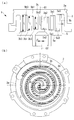
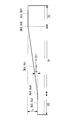
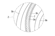
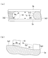
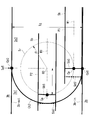
- FIG. 1 The fixed scroll and the turning scroll of the scroll compressor concerning one Embodiment of this invention are shown, (a) is a longitudinal cross-sectional view, (b) is the top view seen from the wall body side of the fixed scroll. It is the perspective view which showed the turning scroll of FIG. It is the top view which showed the end plate flat part provided in the fixed scroll. It is the top view which showed the wall body flat part provided in the fixed scroll. It is a schematic diagram which shows the wall body extended and displayed in the spiral direction. It is the elements on larger scale which expanded and showed the field of the code Z of Drawing 1 (b). 6 shows the tip seal gap in the portion shown in FIG.
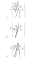
- (a) is a side view showing a state where the tip seal gap is relatively small, and (b) shows a state where the tip seal gap is relatively large. It is a side view. It is the elements on larger scale which showed the end plate inclination connection part periphery.
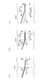
- a positional relationship between a tooth tip and a tooth bottom is shown, (a) is a contact position, (b) is a width center position, and (c) is a side view at a position advanced 180 ° from the width center position.
- the positional relationship between the tooth tip and the tooth bottom in the first embodiment is shown, (a) is a contact position, (b) is a width center position, and (c) is a side view at a position advanced 180 ° from the width center position.
- the processing method of the tooth bottom and wall body side surface concerning 2nd Embodiment is shown, (a) is the top view which planarly viewed the tooth bottom, (b) is a side view. It is the elements on larger scale which showed the end plate inclination connection part periphery.
- a positional relationship between a tooth tip and a tooth bottom is shown, (a) is a width center position, (b) is a contact position, and (c) is a side view at a position advanced 180 ° from the width center position.
- the positional relationship between the tooth tip and the tooth bottom in the second embodiment is shown, (a) is a contact position, (b) is a width center position, and (c) is a side view at a position advanced 180 ° from the width center position.
- It is the top view which showed the processing method of the tooth base and wall surface which concern on 3rd Embodiment.
- FIG. 1 shows a fixed scroll (first scroll member) 3 and a turning scroll (second scroll member) 5 of a scroll compressor (scroll fluid machine) 1.
- the scroll compressor 1 is used as a compressor that compresses a gas refrigerant (fluid) that performs a refrigeration cycle such as an air conditioner.
- the fixed scroll 3 and the orbiting scroll 5 are made of a metal compression mechanism made of aluminum alloy or iron and are housed in a housing (not shown).
- the fixed scroll 3 and the orbiting scroll 5 suck the fluid guided into the housing from the outer peripheral side, and discharge the compressed fluid from the central discharge port 3c of the fixed scroll 3 to the outside.
- the fixed scroll 3 is fixed to the housing and, as shown in FIG. 1A, stands on a substantially disc-shaped end plate (first end plate) 3a and one side surface of the end plate 3a. And a spiral wall body (first wall body) 3b.
- the orbiting scroll 5 includes a substantially disc-shaped end plate (second end plate) 5a and a spiral wall body (second wall body) 5b erected on one side surface of the end plate 5a. .
- the spiral shape of each wall 3b, 5b is defined using, for example, an involute curve or an Archimedean curve.
- the fixed scroll 3 and the orbiting scroll 5 are meshed with their centers separated by an orbiting radius ⁇ , with the phases of the wall bodies 3b and 5b shifted by 180 °, and between the tooth tips and the tooth bottoms of the wall bodies 3b and 5b of both scrolls. It is assembled so as to have a slight clearance in the height direction (chip clearance).
- a plurality of pairs of compression chambers formed between the scrolls 3 and 5 and surrounded by the end plates 3a and 5a and the walls 3b and 5b are formed symmetrically with respect to the scroll center.
- the orbiting scroll 5 revolves around the fixed scroll 3 by a rotation prevention mechanism such as an Oldham ring (not shown).
- the distance L between the facing surfaces 3a and 5a facing each other is continuously decreased from the outer peripheral side to the inner peripheral side of the spiral wall bodies 3b and 5b. Is provided.
- the wall 5b of the orbiting scroll 5 is provided with a wall inclined portion 5b1 whose height continuously decreases from the outer peripheral side toward the inner peripheral side.
- An end plate inclined portion 3a1 (see FIG. 1 (a)) that is inclined according to the inclination of the wall body inclined portion 5b1 is provided on the tooth bottom surface of the fixed scroll 3 where the tooth tips of the wall body inclined portion 5b1 face each other. Yes.
- These wall body inclination part 5b1 and end plate inclination part 3a1 comprise the continuous inclination part.
- the wall body 3b of the fixed scroll 3 is also provided with a wall body inclined portion 3b1 whose height is continuously inclined from the outer peripheral side toward the inner peripheral side, and faces the tooth tip of the wall body inclined portion 3b1.
- An end plate inclined portion 5 a 1 is provided on the end plate 5 a of the orbiting scroll 5.
- the meaning of “continuous in the inclined portion” in the present embodiment is not limited to the smoothly connected inclination, and small steps that are inevitably generated at the time of processing are connected in a staircase shape. If the part as a whole is included, it is continuously inclined. However, large steps such as so-called stepped scrolls are not included.
- the wall body inclined portions 3b1 and 5b1 and / or the end plate inclined portions 3a1 and 5a1 are coated.
- the coating include manganese phosphate treatment and nickel phosphorus plating.
- wall body flat portions 5b2 and 5b3 having a constant height are provided on the innermost circumferential side and the outermost circumferential side of the wall body 5b of the orbiting scroll 5, respectively. .
- These wall flat portions 5b2 and 5b3 are provided over a region of 180 ° around the center O2 (see FIG. 1A) of the orbiting scroll 5.
- Wall body inclined connection portions 5b4 and 5b5 serving as bent portions are respectively provided at positions where the wall body flat portions 5b2 and 5b3 and the wall body inclined portion 5b1 are connected.
- the bottom of the end plate 5a of the orbiting scroll 5 is provided with flat end plates 5a2 and 5a3 having a constant height.
- end plate flat portions 5 a 2 and 5 a 3 are also provided over a 180 ° region around the center of the orbiting scroll 5.
- end plate inclined connecting portions 5a4 and 5a5 serving as bent portions are provided, respectively.
- the fixed scroll 3 also has the end plate flat portions 3a2 and 3a3, the wall body flat portions 3b2 and 3b3, and the end plate inclined connection portions 3a4 and 3a5 in the same manner as the orbiting scroll 5.
- wall body inclination connection part 3b4, 3b5 is provided.
- FIG. 5 shows wall bodies 3b and 5b displayed in a spiral direction.
- the innermost wall flat portions 3b2 and 5b2 are provided over a distance D2
- the outermost wall flat portions 3b3 and 5b3 are provided over a distance D3.
- the distance D2 and the distance D3 are lengths corresponding to the regions 180 degrees around the centers O1 and O2 of the scrolls 3 and 5, respectively.
- Wall body inclined portions 3b1 and 5b1 are provided over the distance D2 between the innermost wall flat portions 3b2 and 5b2 and the outermost wall flat portions 3b3 and 5b3.
- the inclination ⁇ in the inclined portion is constant with respect to the circumferential direction in which the spiral wall bodies 3b and 5b extend.
- FIG. 6 shows an enlarged view of the region indicated by the symbol Z in FIG.
- a tip seal 7 is provided on the tooth tip of the wall 3 b of the fixed scroll 3.
- the tip seal 7 is made of resin and seals the fluid by contacting the tooth bottom of the end plate 5a of the orbiting scroll 5 facing the tip seal 7.
- the tip seal 7 is accommodated in a tip seal groove 3d formed in the tooth tip of the wall 3b over the circumferential direction. The compressed fluid enters the tip seal groove 3d, and the tip seal 7 is pressed from the back and pushed out toward the bottom of the tooth to be brought into contact with the opposing tooth bottom.
- a tip seal is similarly provided on the tooth tip of the wall 5b of the orbiting scroll 5.
- FIG. 7A shows that the tip clearance T is small
- FIG. 7B shows that the tip clearance T is large. Even if the tip clearance T changes due to the swiveling motion, the tip seal 7 is pressed against the tooth bottom side of the end plate 5a by the compressed fluid from the back surface, so that it can be followed and sealed.
- the scroll compressor 1 described above operates as follows.
- the orbiting scroll 5 performs a revolving orbiting motion around the fixed scroll 3 by a driving source such as an electric motor (not shown).
- a driving source such as an electric motor (not shown).
- the fluid is sucked from the outer peripheral side of the scrolls 3 and 5, and the fluid is taken into the compression chambers surrounded by the walls 3b and 5b and the end plates 3a and 5a.
- the fluid in the compression chamber is sequentially compressed as it moves from the outer peripheral side to the inner peripheral side, and finally the compressed fluid is discharged from the discharge port 3 c formed in the fixed scroll 3.
- the inclined portions formed by the end plate inclined portions 3a1 and 5a1 and the wall body inclined portions 3b1 and 5b1 are also compressed in the height direction of the wall bodies 3b and 5b, and three-dimensional compression is performed. Is called.
- FIG. 8 shows a partially enlarged plan view showing the periphery of the end plate inclined connection portion 3a5 of the fixed scroll 3. As shown in FIG. Since the other end plate inclined connection portions 3a4, 5a4, and 5a5 are also described in the same manner, the periphery of the end plate inclined connection portion 3a5 of the fixed scroll 3 will be described below.
- Part 3a1 is provided.
- the wall 5b of the orbiting scroll 5 is shown in FIG.
- the wall 5b has a dimension between the state positioned at the contact position P1 in contact with the inner side 3b-in of the wall 3b on the outer peripheral side of the fixed scroll 3, and the inner side 3b-in and the outer side 3b-out of the wall 3b.
- the state where it is located in the width center position P2 located in the center of the root width Tg direction is shown.
- the contact position P1 is the turning center position in the spiral direction (left-right direction in FIG. 8) during the turning motion.
- symbol W1 is the centerline in the width direction of the wall 5b.
- a contour line Ct1 is shown at the position of the end plate inclined connecting portion 3a5.
- the contour line Ct1 is a line segment formed in a direction orthogonal to the spiral direction of the wall 3b.
- a turning trajectory Tr having a turning radius ⁇ is shown with an intermediate position in the direction of the tooth bottom width Tg of the contour line Ct1 as the center O3.
- the turning trajectory Tr is a trajectory of the intersection Cp where the contour line Ct1 and the center line W1 of the wall 5b intersect when the wall 5b is located at the contact position P1.
- the wall body inclined connection portion 5b5 of the wall body 5b is arranged with a phase delay relative to the end plate inclined connection portion 3a5 by the turning radius ⁇ .
- the reason is as follows. If the wall inclined connection portion 5b5 ′ shown by the broken line is arranged so as to coincide with the contour line Ct1 at the contact position P1, in other words, the wall inclined connection portion 5b5 ′ and the end plate inclined connection portion 3a5 have the same phase.
- FIG. 9 (a) the shape of the tooth bottom (end plate 3a side) and the tooth tip (wall body 5b side) coincide with each other at the contact position P1. If it becomes position P2, as shown in FIG.9 (b), a tooth root and a tooth tip will interfere.
- FIG. 9C shows a position where the phase is further advanced by 180 ° from the width center position P2. Therefore, when the contour line Ct1 is a line segment formed in a direction orthogonal to the spiral direction of the wall body 3b, the wall body inclined connection portion 5b5 ′ and the end plate inclined connection portion 3a5 are arranged in the same phase. I can't.
- the wall body inclined connection portion 5b5 is arranged with a phase delayed by the turning radius ⁇ with respect to the end plate inclined connection portion 3a5 at the contact position P1. .
- the contact position P1 is offset by the turning radius ⁇ , and the tip clearance T at the end plate inclined connecting portion 3a5 becomes ( ⁇ ⁇ tan ⁇ ).
- the tip clearance can be minimized when the turn proceeds to the width center position P2. Note that ⁇ is the inclination of the inclined portion (see FIG. 5).
- the wall inclined connection portions 3b4, 3b5, 5b4, and 5b5 are arranged with the phase delayed by the turning radius ⁇ with respect to the end plate inclined connection portions 3a4, 3a5, 5a4, and 5a5. Thereby, it can avoid that a tooth base and a tooth tip interfere. Further, when the phase of the wall body inclined connection portions 3b4, 3b5, 5b4, 5b5 advances by the turning radius ⁇ with respect to the end plate inclined connection portions 3a4, 3a5, 5a4, 5a5, the end plate inclined connection portions 3a4, 3a5. , 5a4, 5a5 and the wall inclined connection portions 3b4, 3b5, 5b4, 5b5 are engaged with each other so that the tip clearance T between the tooth tip and the tooth bottom can be minimized.
- the contour line Ct1 is a line segment formed in a direction perpendicular to the spiral direction of the wall 3b.
- the present embodiment is different in that the contour line is an arc.
- the contour lines formed as arcs in the end plate inclined portions 3a1 and 5a1 As shown in FIG. With the diameter De of the end mill 10 equal to the root width Tg, the root and the wall side surface are processed in one pass in the upward direction. Processing is performed so that the rotation axis of the end mill 10 is positioned perpendicular to the flat surfaces of the end plate flat portions 3a2, 3a3, 5a2, and 5a3. Thereby, the contour line which becomes a semicircular arc as shown to Fig.11 (a) is formed.
- FIG. 12 shows a contour line Ct2 which is a circular arc obtained by the above-described processing method.
- the contour line Ct2 is a semicircular arc having a root width Tg as a diameter and convex toward the end plate inclined portion 3a1 side (left side in FIG. 12). That is, the radius of the contour line Ct2 is Tg / 2.
- the contour line Ct2 has an intersection Cp0 between the inner side 3b-in of the wall body 3b and the end plate inclined connection portion 3a5 and an intersection point Cp0 between the outer side 3b-out of the wall body 3b and the end plate inclined connection portion 3a5.
- the wall body inclined connection portion 5b5 of the wall body 5b is arranged at the contact position P1 so as to coincide with the turning center position in the spiral direction (left-right direction in FIG. 12) during the turning motion. That is, the wall body inclined connection portion 5b5 and the end plate inclined connection portion 3a5 have the same phase.
- the reason is as follows. If the wall inclined connection portion 5b5 ′ shown by the broken line is arranged so as to coincide with the contour line Ct2 at the width center position P2, as shown in FIG. 13 (b), Tg / 2 ⁇ Only the phase is advanced. However, when the turning proceeds and reaches the width center position P2, the tooth bottom and the tooth tip interfere with each other as shown in FIG. FIG.
- 13C shows a position where the phase is further advanced by 180 ° from the width center position P2. Therefore, when the contour line Ct2 is a semicircular arc having a diameter equivalent to the root width Tg, the phase of the wall inclined connection portion 5b5 ′ cannot be advanced more than that of the end plate inclined connection portion 3a5.
- the wall body inclined connection portion 5b5 is disposed so as to be in phase with the end plate inclined connection portion 3a5 at the contact position P1.
- the contact position P1 it will become the position where the side surface shape of the tooth tip and the side surface shape of the tooth root corresponded.
- the tip clearance T at the width center of the contour line Ct2 becomes ⁇ (Tg / 2 ⁇ ) ⁇ tan ⁇ at the width center position P2, as shown in FIG. 14B.
- one semicircular arc having a contact point at the intersection Cp0 between the end plate inclined connecting portion 3a5 and the wall body 3b is formed as a contour line Ct2.
- the wall inclined connection portion 5b5 is arranged so as to coincide with the end position of the inclined connection portion 3a5 at the turning center position (contact position P1) in the spiral direction during the turning motion, that is, in the same phase.
- the tip clearance and the tooth bottom do not interfere with each other during the turning motion, and the tip clearance can be made as small as possible.
- the tip clearance T between the tooth tip and the tooth bottom becomes the smallest between the contacting wall bodies 3b and 5b when in the contact position P1
- leakage in the spiral direction of the wall body 3b can be reduced. That is, as shown in FIG. 15, a region A surrounded by the tooth tip of the wall 5b, the tip seal 7, the tooth bottom of the end plate 3a, and the side surface of the wall 3b is a leakage gap in the spiral direction.
- Reference numeral 5d denotes a tip seal groove formed at the tip of the wall 5b.
- the present embodiment differs from the second embodiment in the shape around the end plate inclined connection portion 3a5 shown in FIG. 12, and the other configurations are the same as those in the second embodiment. Accordingly, differences from the second embodiment will be described, and the same reference numerals are given to the same configurations, and the description thereof will be omitted.
- the contour line Ct2 is one semicircular arc, but in the present embodiment, the contour line is two arcs having the same diameter.
- FIG. 16 is a view corresponding to FIG. 11A, and the end mill 10 is machined by cutting twice (two passes) so as to be inclined in the spiral direction of the wall bodies 3b and 5b. That is, the side wall of one wall 3b and the tooth bottom connected thereto are processed by the first cutting, and the side wall of the other wall 3b and the tooth bottom connected thereto are processed by the second cutting.
- a shape in which two semicircular arcs are connected at the center of the width is a contour line Ct3. Therefore, in the present embodiment, the relationship is (end mill diameter De ⁇ bottom width Tg).
- FIG. 17 shows a contour line Ct3 that is an arc obtained by the above-described processing method.
- the contour line Ct3 has a shape in which two arcs having the end mill diameter De as a diameter are connected at the center of the width of the root, and each arc has an end plate inclined portion 3a1 side ( It is convex on the left side in the figure.
- the contour line Ct3 has a contact point at an intersection Cp0 between the inner side 3b-in of the wall body 3b and the end plate inclined connection portion 3a5 and an intersection point Cp0 between the outer side 3b-out of the wall body 3b and the end plate inclination connection portion 3a5.
- the wall body inclined connection portion 5b5 of the wall body 5b is arranged at the contact position P1 so as to coincide with the center position of the swirl in the swirling direction (left-right direction in FIG. 17) during the swiveling motion. That is, the wall body inclined connection portion 5b5 and the end plate inclined connection portion 3a5 have the same phase. The reason is that, as described in the second embodiment, the tooth tip does not contact the tooth bottom and the tip clearance is made as small as possible.
- the tip clearance when the wall body 5b advances to the width center position P2 is advantageous as compared with the second embodiment. This is because the distance R from the center O3 of the turning locus Tr to the contour line Ct3 is shorter than the corresponding distance Tg / 2 (see FIG. 12) of the second embodiment, as is apparent from FIG. .
- the distance R is made equal to the turning radius ⁇ .
- R ⁇ into the above equation (3) to solve, the following equation is derived.
- De ⁇ Tg 2 + (2 ⁇ ) 2 ⁇ / (2Tg) (4) That is, the contour line Ct3 formed with the end mill diameter De may be used so as to satisfy the above equation.
- the distance R can be made shorter than Tg / 2, so that the chip clearance can be reduced and leakage can be reduced as compared with the second embodiment.
- contour line Ct3 by two arcs having an end mill diameter De satisfying the expression (4), the contour line Ct3 and the wall inclined connection portion 5b5 when the tooth tip and the tooth bottom are closest to each other during the turning motion.
- the contour line Ct3 is composed of two arcs having the same diameter, but may be a contour line composed of three or more arcs.
- the flat part is not provided in the outermost periphery side and / or the innermost periphery side. It can also be applied to configurations.
- the fixed scroll 3 and the orbiting scroll 5 are arranged with their phases shifted by the amount of the orbiting radius in the direction in which the inclined portions facing each other move away.
- the fixed scroll 3 and the orbiting scroll 5 are arranged so that the phases coincide with each other at the orbital center position in the spiral direction during the orbiting motion.
- the scroll compressor has been described.
- the present invention can be applied to a scroll expander used as an expander.
- Scroll compressor (scroll fluid machine) 3 Fixed scroll (first scroll member) 3a End plate (first end plate) 3a1 End plate inclined part 3a2 End plate flat part (inner peripheral side) 3a3 Flat end plate (outside) 3a4 End plate inclined connection (inner circumference side) 3a5 End plate inclined connection (outer side) 3b Wall (first wall) 3b1 Wall body inclined part 3b2 Wall body flat part (inner circumference side) 3b3 Wall flat part (outside) 3b4 Wall inclined connection (inner circumference side) 3b5 Inclined wall connection (outside) 3c Discharge port 5 Orbiting scroll (second scroll member) 5a End plate (second end plate) 5a1 End plate inclined part 5a2 End plate flat part (inner peripheral side) 5a3 Flat end plate (outside) 5b Wall body (second wall body) 5b1 Wall body inclined part 5b2 Wall body flat part (inner circumference side) 5b3 Wall flat part (outside) 5b4 Wall body inclined connection (inner circumference side) 5
Landscapes
- Engineering & Computer Science (AREA)
- Mechanical Engineering (AREA)
- General Engineering & Computer Science (AREA)
- Rotary Pumps (AREA)
- Applications Or Details Of Rotary Compressors (AREA)
Abstract
歯先と歯底との間のチップクリアランスを小さくすることを目的とする。 固定スクロールの端板には、壁体傾斜部の歯先に対向する歯底面が壁体傾斜部の傾斜に応じて傾斜する端板傾斜部(3a1)が設けられている。端板傾斜部(3a1)には、壁体(3b)の渦巻き方向に直交する方向に等高線(Ct1)が形成され、端板傾斜部(3a1)と端板平坦部(3a3)とが接続される端板傾斜接続部(3a5)に対して、壁体傾斜部と壁体平坦部とが接続される壁体傾斜接続部(5b5)が、旋回半径ρ分だけ位相が遅れて配置されている。
Description
本発明は、スクロール流体機械に関するものである。
一般に、端板上に渦巻状の壁体が設けられた固定スクロール部材と旋回スクロール部材とを噛み合わせ、公転旋回運動を行わせて流体を圧縮または膨張するスクロール流体機械が知られている。
このようなスクロール流体機械として、特許文献1に示すようないわゆる段付きスクロール圧縮機が知られている。この段付きスクロール圧縮機は、固定スクロールおよび旋回スクロールの渦巻状の壁体の歯先面および歯底面の渦巻き方向に沿う位置に各々段部が設けられ、各段部を境に壁体の外周側の高さが内周側の高さよりも高くされている。段付きスクロール圧縮機は、壁体の周方向だけでなく、高さ方向にも圧縮(三次元圧縮)されるため、段部を備えていない一般的なスクロール圧縮機(二次元圧縮)に比べ、押しのけ量を大きくし、圧縮機容量を増加することができる。
しかし、段付きスクロール圧縮機は、段部における流体漏れが大きいという問題がある。また、段部の根元部分に応力が集中して強度が低下するという問題がある。
これに対して、発明者等は、壁体及び端板に設けられた段部に代えて連続的な傾斜部を設けることを検討している。
しかし、傾斜部を設けるとしても、壁体の歯先と端板の歯底との間のチップクリアランスに起因する流体漏れの低減が望まれる。
しかし、傾斜部を設けるとしても、壁体の歯先と端板の歯底との間のチップクリアランスに起因する流体漏れの低減が望まれる。
本発明は、このような事情に鑑みてなされたものであって、壁体の歯先と端板の歯底との間のチップクリアランスを小さくすることが可能な壁体及び端板に傾斜部を有するスクロール流体機械を提供することを目的とする。
上記課題を解決するために、本発明のスクロール流体機械は以下の手段を採用する。
すなわち、本発明の第一の態様にかかるスクロール流体機械は、第1端板上に渦巻状の第1壁体が設けられた第1スクロール部材と、前記第1端板に向かい合うように配置された第2端板上に渦巻状の第2壁体が設けられ、該第2壁体が前記第1壁体と旋回半径分だけオフセットされて噛み合って相対的に公転旋回運動を行う第2スクロール部材とを備えたスクロール流体機械であって、向かい合う前記第1端板と前記第2端板との対向面間距離が、前記第1壁体及び前記第2壁体の外周側から内周側に向かって、連続的に減少する傾斜部が設けられ、前記第1壁体および前記第2壁体の少なくともいずれか一方は、前記傾斜部を形成するように外周側から内周側に向かって該壁体の高さが連続的に減少する壁体傾斜部を有し、前記第1端板および前記第2端板の少なくともいずれか一方は、前記壁体傾斜部の歯先に対向する歯底面が該壁体傾斜部の傾斜に応じて傾斜する端板傾斜部を有し、前記端板傾斜部には、前記壁体の渦巻き方向に直交する方向に等高線が形成され、前記第1スクロール部材と前記第2スクロール部材とが、対向する前記傾斜部同士が遠ざかる方向に前記旋回半径分だけ位相がずらされて配置されている。
第1端板と第2端板との対向面間距離が壁体の外周側から内周側に向かって連続的に減少する傾斜部が設けられているので、外周側から吸い込まれた流体は内周側に向かうにしたがい、壁体の渦巻形状に応じた圧縮室の減少によって圧縮されるだけでなく、端板間の対向面間距離の減少によって更に圧縮されることになる。
端板傾斜部すなわち歯底に、壁体の渦巻き方向に直交する方向に等高線が形成されている。この場合に、前記第1スクロール部材と前記第2スクロール部材とを渦巻き方向における旋回中央位置で一致させておくと、両スクロール部材が旋回運動を行った際に歯底と歯先が干渉するおそれがある。そこで、前記第1スクロール部材と前記第2スクロール部材とを対向する傾斜部同士が遠ざかる方向に旋回半径分だけ位相をずらされて配置するようにした。これにより、歯底と歯先が干渉することを回避できる。また、旋回半径分だけ位相が進んだ場合に、傾斜部の位置が一致するように噛み合うので、歯先と歯底との間のチップクリアランスを小さくすることができる。
端板傾斜部すなわち歯底に、壁体の渦巻き方向に直交する方向に等高線が形成されている。この場合に、前記第1スクロール部材と前記第2スクロール部材とを渦巻き方向における旋回中央位置で一致させておくと、両スクロール部材が旋回運動を行った際に歯底と歯先が干渉するおそれがある。そこで、前記第1スクロール部材と前記第2スクロール部材とを対向する傾斜部同士が遠ざかる方向に旋回半径分だけ位相をずらされて配置するようにした。これにより、歯底と歯先が干渉することを回避できる。また、旋回半径分だけ位相が進んだ場合に、傾斜部の位置が一致するように噛み合うので、歯先と歯底との間のチップクリアランスを小さくすることができる。
さらに、本発明の第一の態様にかかるスクロール流体機械は、前記第1端板および前記第2端板の少なくともいずれか一方は、前記壁体傾斜部の歯先に対向する歯底面が該壁体傾斜部の傾斜に応じて傾斜する端板傾斜部を有し、前記第1壁体および前記第2壁体の最外周部および/または最内周部には、高さが変化しない壁体平坦部が設けられ、前記第1端板および前記第2端板には、前記壁体平坦部に対応した端板平坦部が設けられ、前記端板傾斜部と前記端板平坦部とが接続される端板傾斜接続部に対して、前記壁体傾斜部と前記壁体平坦部とが接続される壁体傾斜接続部が、前記旋回半径分だけ位相が遅れて配置されている。
端板傾斜部すなわち歯底に、壁体の渦巻き方向に直交する方向に等高線が形成されている。この場合に、端板傾斜部と端板平坦部とが接続される端板傾斜接続部と、壁体傾斜部と壁体平坦部とが接続される壁体傾斜接続部とを渦巻き方向における旋回中央位置で一致させておくと、両スクロール部材が旋回運動を行った際に歯底と歯先が干渉するおそれがある。そこで、端板傾斜接続部に対して壁体傾斜接続部を旋回半径分だけ位相を遅らせて配置するようにした。これにより、歯底と歯先が干渉することを回避できる。また、端板傾斜接続部に対して壁体傾斜接続部が旋回半径分だけ位相が進んだ場合に、端板傾斜接続部と壁体傾斜接続部との位置が一致するように噛み合うので、歯先と歯底との間のチップクリアランスを小さくすることができる。
また、本発明の第二の態様にかかるスクロール流体機械は、第1端板上に渦巻状の第1壁体が設けられた第1スクロール部材と、前記第1端板に向かい合うように配置された第2端板上に渦巻状の第2壁体が設けられ、該第2壁体が前記第1壁体と旋回半径分だけオフセットされて噛み合って相対的に公転旋回運動を行う第2スクロール部材とを備えたスクロール流体機械であって、向かい合う前記第1端板と前記第2端板との対向面間距離が、前記第1壁体及び前記第2壁体の外周側から内周側に向かって、連続的に減少する傾斜部が設けられ、前記第1壁体および前記第2壁体の少なくともいずれか一方は、前記傾斜部を形成するように外周側から内周側に向かって該壁体の高さが連続的に減少する壁体傾斜部を有し、前記第1端板および前記第2端板の少なくともいずれか一方は、前記壁体傾斜部の歯先に対向する歯底面が該壁体傾斜部の傾斜に応じて傾斜する端板傾斜部を有し、前記端板傾斜部には、前記壁体との交点を接点とする1又は複数の円弧が等高線として形成され、前記第1スクロール部材と前記第2スクロール部材とが、前記旋回運動時の渦巻き方向における旋回中央位置で一致する位相となるように配置されている。
第1端板と第2端板との対向面間距離が壁体の外周側から内周側に向かって連続的に減少する傾斜部が設けられているので、外周側から吸い込まれた流体は内周側に向かうにしたがい、壁体の渦巻形状に応じた圧縮室の減少によって圧縮されるだけでなく、端板間の対向面間距離の減少によって更に圧縮されることになる。
端板傾斜部に、壁体との交点を接点とする1又は複数の円弧が等高線として形成されている。この場合には、第1スクロール部材と前記第2スクロール部材とが、旋回運動時の渦巻き方向における旋回中央位置で一致する位相となるように、すなわち第1スクロール部材と前記第2スクロール部材とが同位相となるように配置すれば、旋回運動時に歯先と歯底が干渉することがなく、また歯先と歯底との間のチップクリアランスを小さくすることができる。
端板傾斜部に、前記壁体との交点を接点とする1又は複数の円弧を等高線として形成するには、端板傾斜部の歯底幅と同等かそれ以下の直径を有するエンドミルを用いて加工することが好ましい。
端板傾斜部に、壁体との交点を接点とする1又は複数の円弧が等高線として形成されている。この場合には、第1スクロール部材と前記第2スクロール部材とが、旋回運動時の渦巻き方向における旋回中央位置で一致する位相となるように、すなわち第1スクロール部材と前記第2スクロール部材とが同位相となるように配置すれば、旋回運動時に歯先と歯底が干渉することがなく、また歯先と歯底との間のチップクリアランスを小さくすることができる。
端板傾斜部に、前記壁体との交点を接点とする1又は複数の円弧を等高線として形成するには、端板傾斜部の歯底幅と同等かそれ以下の直径を有するエンドミルを用いて加工することが好ましい。
また、本発明の第二の態様にかかるスクロール流体機械は、第1端板上に渦巻状の第1壁体が設けられた第1スクロール部材と、前記第1端板に向かい合うように配置された第2端板上に渦巻状の第2壁体が設けられ、該第2壁体が前記第1壁体と旋回半径分だけオフセットされて噛み合って相対的に公転旋回運動を行う第2スクロール部材とを備えたスクロール流体機械であって、向かい合う前記第1端板と前記第2端板との対向面間距離が、前記第1壁体及び前記第2壁体の外周側から内周側に向かって、連続的に減少する傾斜部が設けられ、前記第1壁体および前記第2壁体の少なくともいずれか一方は、前記傾斜部を形成するように外周側から内周側に向かって該壁体の高さが連続的に減少する壁体傾斜部を有し、前記第1端板および前記第2端板の少なくともいずれか一方は、前記壁体傾斜部の歯先に対向する歯底面が該壁体傾斜部の傾斜に応じて傾斜する端板傾斜部を有し、前記第1壁体および前記第2壁体の最外周部および/または最内周部には、高さが変化しない壁体平坦部が設けられ、前記第1端板および前記第2端板には、前記壁体平坦部に対応した端板平坦部が設けられ、前記端板傾斜部には、該端板傾斜部と前記端板平坦部とが接続される端板傾斜接続部と前記壁体との交点を接点とする1又は複数の円弧が等高線として形成され、前記端板傾斜接続部に対して、前記壁体傾斜部と前記壁体平坦部とが接続される壁体傾斜接続部が、前記旋回運動時の渦巻き方向における旋回中央位置で一致するように配置されている。
端板傾斜部に、端板傾斜部と端板平坦部とが接続される端板傾斜接続部と前記壁体との交点を接点とする1又は複数の円弧が等高線として形成されている。この場合には、端板傾斜接続部に対して、壁体傾斜接続部が、旋回運動時の渦巻き方向における旋回中央位置で一致するように、すなわち端板傾斜接続部と壁体傾斜接続部とが同位相となるように配置すれば、旋回運動時に歯先と歯底が干渉することがなく、また歯先と歯底との間のチップクリアランスを小さくすることができる。
端板傾斜部に、端板傾斜接続部と前記壁体との交点を接点とする1又は複数の円弧を等高線として形成するには、端板傾斜部の歯底幅と同等かそれ以下の直径を有するエンドミルを用いて加工することが好ましい。
端板傾斜部に、端板傾斜接続部と前記壁体との交点を接点とする1又は複数の円弧を等高線として形成するには、端板傾斜部の歯底幅と同等かそれ以下の直径を有するエンドミルを用いて加工することが好ましい。
さらに、本発明の第二の態様にかかるスクロール流体機械によれば、前記等高線を形成する円弧の直径をDeとし、前記端板傾斜部の歯底幅をTg、旋回運動の旋回半径をρとした場合に、
{Tg2+(2ρ)2}/(2Tg)≦De≦Tg
とされている。
{Tg2+(2ρ)2}/(2Tg)≦De≦Tg
とされている。
上式の関係式を満たすことにより、旋回運動時に歯先と歯底が近づいて互いに干渉することを回避することができる。
さらに、本発明の第二の態様にかかるスクロール流体機械によれば、
De={Tg2+(2ρ)2}/(2Tg)
とされている。
De={Tg2+(2ρ)2}/(2Tg)
とされている。
De={Tg2+(2ρ)2}/(2Tg)とすることにより、旋回運動時に歯先と歯底が最も近づいたときに等高線と壁体傾斜接続部と間におけるチップクリアランスをゼロに近づけることができる。
端板傾斜部すなわち歯底に、渦巻き方向に直交する方向に等高線が形成されている場合に、端板傾斜接続部に対して壁体傾斜接続部を旋回半径分だけ位相が遅れて配置されるようにした。これにより、旋回運動時に歯先と歯底が干渉することがなく、また歯先と歯底との間のチップクリアランスを小さくすることができる。
端板傾斜部に、端板傾斜接続部と前記壁体との交点を接点とする1又は複数の円弧が等高線として形成されている場合に、端板傾斜接続部に対して、壁体傾斜接続部が、旋回運動時の渦巻き方向における旋回中央位置で一致するように配置されるようにした。これにより、旋回運動時に歯先と歯底が干渉することがなく、また歯先と歯底との間のチップクリアランスを小さくすることができる。
[第1実施形態]
以下に、本発明にかかる第1実施形態について、図面を参照して説明する。
図1には、スクロール圧縮機(スクロール流体機械)1の固定スクロール(第1スクロール部材)3と旋回スクロール(第2スクロール部材)5が示されている。スクロール圧縮機1は、例えば空調機等の冷凍サイクルを行うガス冷媒(流体)を圧縮する圧縮機として用いられる。
以下に、本発明にかかる第1実施形態について、図面を参照して説明する。
図1には、スクロール圧縮機(スクロール流体機械)1の固定スクロール(第1スクロール部材)3と旋回スクロール(第2スクロール部材)5が示されている。スクロール圧縮機1は、例えば空調機等の冷凍サイクルを行うガス冷媒(流体)を圧縮する圧縮機として用いられる。
固定スクロール3及び旋回スクロール5は、アルミ合金製や鉄製等の金属製の圧縮機構とされ、図示しないハウジング内に収容されている。固定スクロール3及び旋回スクロール5は、ハウジング内に導かれた流体を外周側から吸い込み、固定スクロール3の中央の吐出ポート3cから外部へと圧縮後の流体を吐出する。
固定スクロール3は、ハウジングに固定されており、図1(a)に示されているように、略円板形状の端板(第1端板)3aと、端板3aの一側面上に立設された渦巻状の壁体(第1壁体)3bとを備えている。旋回スクロール5は、略円板形状の端板(第2端板)5aと、端板5aの一側面上に立設された渦巻状の壁体(第2壁体)5bとを備えている。各壁体3b,5bの渦巻形状は、例えば、インボリュート曲線やアルキメデス曲線を用いて定義されている。
固定スクロール3と旋回スクロール5は、その中心を旋回半径ρだけ離し、壁体3b,5bの位相を180°ずらして噛み合わされ、両スクロールの壁体3b、5bの歯先と歯底間に常温で僅かな高さ方向のクリアランス(チップクリアランス)を有するように組み付けられている。これにより、両スクロール3,5間に、その端板3a,5aと壁体3b、5bとにより囲まれて形成される複数対の圧縮室がスクロール中心に対して対称に形成される。旋回スクロール5は、図示しないオルダムリング等の自転防止機構によって固定スクロール3の周りを公転旋回運動する。
図1(a)に示すように、向かい合う両端板3a,5a間の対向面間距離Lが、渦巻状の壁体3b,5bの外周側から内周側に向かって、連続的に減少する傾斜部が設けられている。
図2に示すように、旋回スクロール5の壁体5bには、外周側から内周側に向かって高さが連続的に減少する壁体傾斜部5b1が設けられている。この壁体傾斜部5b1の歯先が対向する固定スクロール3の歯底面には、壁体傾斜部5b1の傾斜に応じて傾斜する端板傾斜部3a1(図1(a)参照)が設けられている。これら壁体傾斜部5b1及び端板傾斜部3a1によって、連続的な傾斜部が構成されている。同様に、固定スクロール3の壁体3bにも高さが外周側から内周側に向かって連続的に傾斜する壁体傾斜部3b1が設けられ、この壁体傾斜部3b1の歯先に対向する端板傾斜部5a1が旋回スクロール5の端板5aに設けられている。
なお、本実施形態でいう傾斜部における連続的という意味は、滑らかに接続された傾斜に限定されるものではなく、加工時に不可避的に生じるような小さな段差が階段状に接続されており、傾斜部を全体としてみれば連続的に傾斜しているものも含まれる。ただし、いわゆる段付きスクロールのような大きな段差は含まれない。
壁体傾斜部3b1,5b1及び/又は端板傾斜部3a1,5a1には、コーティングが施されている。コーティングとしては、例えば、リン酸マンガン処理やニッケルリンめっき等が挙げられる。
図2に示されているように、旋回スクロール5の壁体5bの最内周側と最外周側には、それぞれ、高さが一定とされた壁体平坦部5b2,5b3が設けられている。これら壁体平坦部5b2,5b3は、旋回スクロール5の中心O2(図1(a)参照)まわりに180°の領域にわたって設けられている。壁体平坦部5b2,5b3と壁体傾斜部5b1とが接続される位置には、それぞれ、屈曲部となる壁体傾斜接続部5b4,5b5が設けられている。
旋回スクロール5の端板5aの歯底についても同様に、高さが一定とされた端板平坦部5a2,5a3が設けられている。これら端板平坦部5a2,5a3についても、旋回スクロール5の中心まわりに180°の領域にわたって設けられている。端板平坦部5a2,5a3と端板傾斜部5a1とが接続される位置には、それぞれ、屈曲部となる端板傾斜接続部5a4,5a5が設けられている。
旋回スクロール5の端板5aの歯底についても同様に、高さが一定とされた端板平坦部5a2,5a3が設けられている。これら端板平坦部5a2,5a3についても、旋回スクロール5の中心まわりに180°の領域にわたって設けられている。端板平坦部5a2,5a3と端板傾斜部5a1とが接続される位置には、それぞれ、屈曲部となる端板傾斜接続部5a4,5a5が設けられている。
図3及び図4にハッチングにて示すように、固定スクロール3についても、旋回スクロール5と同様に、端板平坦部3a2,3a3、壁体平坦部3b2,3b3、端板傾斜接続部3a4,3a5及び壁体傾斜接続部3b4,3b5が設けられている。
図5には、渦巻き方向に伸ばして表示した壁体3b,5bが示されている。同図に示されているように、最内周側の壁体平坦部3b2,5b2が距離D2にわたって設けられ、最外周側の壁体平坦部3b3,5b3が距離D3にわたって設けられている。距離D2及び距離D3は、それぞれ、各スクロール3,5の中心O1,O2まわりに180°とされた領域に相当する長さとなっている。最内周側の壁体平坦部3b2,5b2と最外周側の壁体平坦部3b3,5b3との間に、壁体傾斜部3b1,5b1が距離D2にわたって設けられている。最内周側の壁体平坦部3b2,5b2と最外周側の壁体平坦部3b3,5b3との高低差をhとすると、壁体傾斜部3b1,5b1の傾きφは下式とされる。
φ=tan-1(h/D1) ・・・(1)
このように、傾斜部における傾きφは、渦巻状の壁体3b,5bが延在する周方向に対して一定とされている。
φ=tan-1(h/D1) ・・・(1)
このように、傾斜部における傾きφは、渦巻状の壁体3b,5bが延在する周方向に対して一定とされている。
図6には、図1(b)の符号Zで示した領域の拡大図が示されている。図6に示されているように、固定スクロール3の壁体3bの歯先には、チップシール7が設けられている。チップシール7は樹脂製とされており、対向する旋回スクロール5の端板5aの歯底に接触して流体をシールする。チップシール7は、壁体3bの歯先に周方向にわたって形成されたチップシール溝3d内に収容されている。このチップシール溝3d内に圧縮流体が入り込み、チップシール7を背面から押圧して歯底側に押し出すことで対向する歯底に接触させるようになっている。なお、旋回スクロール5の壁体5bの歯先に対しても、同様にチップシールが設けられている。
両スクロール3,5が相対的に公転旋回運動を行うと、旋回直径(旋回半径ρ×2)分だけ歯先と歯底の位置が相対的にずれる。この歯先と歯底の位置ずれに起因して、傾斜部では、歯先と歯底との間のチップクリアランスが変化する。例えば、図7(a)ではチップクリアランスTが小さく、図7(b)ではチップクリアランスTが大きいことを示している。チップシール7は、このチップクリアランスTが旋回運動によって変化しても、背面から圧縮流体によって端板5aの歯底側に押圧されるので、追従してシールできるようになっている。
上述したスクロール圧縮機1は、以下のように動作する。
図示しない電動モータ等の駆動源によって、旋回スクロール5が固定スクロール3回りに公転旋回運動を行う。これにより、各スクロール3,5の外周側から流体を吸い込み、各壁体3b,5b及び各端板3a,5aによって囲まれた圧縮室に流体を取り込む。圧縮室内の流体は外周側から内周側に移動するに従い順次圧縮され、最終的に固定スクロール3に形成された吐出ポート3cから圧縮流体が吐出される。流体が圧縮される際に、端板傾斜部3a1,5a1及び壁体傾斜部3b1,5b1によって形成された傾斜部では壁体3b,5bの高さ方向にも圧縮されて、三次元圧縮が行われる。
図示しない電動モータ等の駆動源によって、旋回スクロール5が固定スクロール3回りに公転旋回運動を行う。これにより、各スクロール3,5の外周側から流体を吸い込み、各壁体3b,5b及び各端板3a,5aによって囲まれた圧縮室に流体を取り込む。圧縮室内の流体は外周側から内周側に移動するに従い順次圧縮され、最終的に固定スクロール3に形成された吐出ポート3cから圧縮流体が吐出される。流体が圧縮される際に、端板傾斜部3a1,5a1及び壁体傾斜部3b1,5b1によって形成された傾斜部では壁体3b,5bの高さ方向にも圧縮されて、三次元圧縮が行われる。
図8には、固定スクロール3の端板傾斜接続部3a5周りを示した部分拡大平面図が示されている。なお、他の端板傾斜接続部3a4,5a4,5a5周りについても同様の説明となるので、以下では固定スクロール3の端板傾斜接続部3a5周りについて説明する。
同図において、固定スクロール3の外周側の壁体3bの内側3b-inと内周側の壁体3bの外側3b-outとの間に、最外周側の端板平坦部3a3と端板傾斜部3a1とが設けられている。また、同図中には旋回スクロール5の壁体5bが示されている。壁体5bは、固定スクロール3の外周側の壁体3bの内側3b-inに接した接触位置P1に位置した状態と、壁体3bの内側3b-inと外側3b-outとの間の寸法である歯底幅Tg方向の中央に位置する幅中央位置P2に位置した状態とが示されている。接触位置P1は、旋回運動時の渦巻き方向(図8において左右方向)における旋回中央位置となる。なお、符号W1は、壁体5bの幅方向における中心線である。
端板傾斜接続部3a5の位置には、等高線Ct1が示されている。等高線Ct1は、壁体3bの渦巻き方向に直交する方向に形成された線分となっている。等高線Ct1の歯底幅Tg方向における中間位置を中心O3として、旋回半径ρとされた旋回軌跡Trが示されている。この旋回軌跡Trは、壁体5bが接触位置P1に位置しているときの等高線Ct1と壁体5bの中心線W1とが交わる交点Cpの軌跡である。
壁体5bの壁体傾斜接続部5b5は、接触位置P1から分かるように、端板傾斜接続部3a5に対して、旋回半径ρ分だけ位相が遅れて配置されている。この理由は以下の通りである。
仮に破線で示した壁体傾斜接続部5b5’を接触位置P1にて等高線Ct1と一致するように配置すると、換言すると壁体傾斜接続部5b5’と端板傾斜接続部3a5とを同位相とすると、図9(a)に示すように、接触位置P1では歯底(端板3a側)と歯先(壁体5b側)との形状が一致した状態となっているが、旋回が進み幅中央位置P2となると、図9(b)に示すように歯底と歯先とが干渉してしまうことになる。なお、図9(c)は、幅中央位置P2から更に位相が180°進んだ位置である。
したがって、等高線Ct1が壁体3bの渦巻き方向に直交する方向に形成された線分となっている場合には、壁体傾斜接続部5b5’と端板傾斜接続部3a5とを同位相に配置することができない。
仮に破線で示した壁体傾斜接続部5b5’を接触位置P1にて等高線Ct1と一致するように配置すると、換言すると壁体傾斜接続部5b5’と端板傾斜接続部3a5とを同位相とすると、図9(a)に示すように、接触位置P1では歯底(端板3a側)と歯先(壁体5b側)との形状が一致した状態となっているが、旋回が進み幅中央位置P2となると、図9(b)に示すように歯底と歯先とが干渉してしまうことになる。なお、図9(c)は、幅中央位置P2から更に位相が180°進んだ位置である。
したがって、等高線Ct1が壁体3bの渦巻き方向に直交する方向に形成された線分となっている場合には、壁体傾斜接続部5b5’と端板傾斜接続部3a5とを同位相に配置することができない。
そこで、本実施形態では、図8に示したように、壁体傾斜接続部5b5を、接触位置P1にて端板傾斜接続部3a5に対して旋回半径ρ分だけ位相を遅らせて配置している。これにより、図10(a)に示すように、接触位置P1では旋回半径ρ分だけオフセットされた位置となり、端板傾斜接続部3a5におけるチップクリアランスTが(ρ×tanφ)となってしまうが、図10(b)に示すように幅中央位置P2まで旋回が進んだときにチップクリアランスを最小にすることができる。なお、φは傾斜部の傾きである(図5参照)。
本実施形態によれば、以下の作用効果を奏する。
端板傾斜部3a1,5a1すなわち歯底に、壁体3b,5bの渦巻き方向に直交する方向に等高線Ct1が形成されている場合に、端板傾斜接続部3a4,3a5,5a4,5a5と壁体傾斜接続部3b4,3b5,5b4,5b5とを、渦巻き方向における旋回中央位置(接触位置P1)で一致させておくと、両スクロール3,5が旋回運動を行った際に歯底と歯先が干渉するおそれがある。そこで、端板傾斜接続部3a4,3a5,5a4,5a5に対して壁体傾斜接続部3b4,3b5,5b4,5b5を旋回半径ρ分だけ位相を遅らせて配置することとした。これにより、歯底と歯先が干渉することを回避できる。また、端板傾斜接続部3a4,3a5,5a4,5a5に対して壁体傾斜接続部3b4,3b5,5b4,5b5が旋回半径ρ分だけ位相が進んだ場合に、端板傾斜接続部3a4,3a5,5a4,5a5と壁体傾斜接続部3b4,3b5,5b4,5b5との位置が一致するように噛み合うので、歯先と歯底との間のチップクリアランスTを最小にすることができる。
端板傾斜部3a1,5a1すなわち歯底に、壁体3b,5bの渦巻き方向に直交する方向に等高線Ct1が形成されている場合に、端板傾斜接続部3a4,3a5,5a4,5a5と壁体傾斜接続部3b4,3b5,5b4,5b5とを、渦巻き方向における旋回中央位置(接触位置P1)で一致させておくと、両スクロール3,5が旋回運動を行った際に歯底と歯先が干渉するおそれがある。そこで、端板傾斜接続部3a4,3a5,5a4,5a5に対して壁体傾斜接続部3b4,3b5,5b4,5b5を旋回半径ρ分だけ位相を遅らせて配置することとした。これにより、歯底と歯先が干渉することを回避できる。また、端板傾斜接続部3a4,3a5,5a4,5a5に対して壁体傾斜接続部3b4,3b5,5b4,5b5が旋回半径ρ分だけ位相が進んだ場合に、端板傾斜接続部3a4,3a5,5a4,5a5と壁体傾斜接続部3b4,3b5,5b4,5b5との位置が一致するように噛み合うので、歯先と歯底との間のチップクリアランスTを最小にすることができる。
[第2実施形態]
次に、本発明の第2実施形態について説明する。本実施形態は、第1実施形態に対して図8に示した端板傾斜接続部3a5周りの形状が異なり、その他の構成は第1実施形態と同様である。したがって、第1実施形態との相違点について説明し、同様の構成については同一符号を付しその説明を省略する。
次に、本発明の第2実施形態について説明する。本実施形態は、第1実施形態に対して図8に示した端板傾斜接続部3a5周りの形状が異なり、その他の構成は第1実施形態と同様である。したがって、第1実施形態との相違点について説明し、同様の構成については同一符号を付しその説明を省略する。
第1実施形態では等高線Ct1が壁体3bの渦巻き方向に直交する方向に形成された線分とされていたが、本実施形態では等高線が円弧とされている点で相違する。
円弧とされた等高線を端板傾斜部3a1,5a1に形成するには、図11に示すように、エンドミル10での加工によって行う。エンドミル10の直径Deを歯底幅Tgと同等として、傾斜を上る一方向に1パスで歯底と壁体側面の加工を行う。エンドミル10の回転軸線を端板平坦部3a2,3a3,5a2,5a3の平坦面に対して垂直に位置するようにして加工する。これにより、図11(a)に示したような半円弧となる等高線が形成される。
図12には、上述した加工法によって得られた円弧とされた等高線Ct2が示されている。同図は、第1実施形態の図8に対応する図である。
図12に示されているように、等高線Ct2は、歯底幅Tgを直径とし、端板傾斜部3a1側(同図において左側)に凸とされた半円弧となっている。つまり、等高線Ct2の半径はTg/2となる。等高線Ct2は、壁体3bの内側3b-inと端板傾斜接続部3a5との交点Cp0と、壁体3bの外側3b-outと端板傾斜接続部3a5との交点Cp0とを接点としている。
図12に示されているように、等高線Ct2は、歯底幅Tgを直径とし、端板傾斜部3a1側(同図において左側)に凸とされた半円弧となっている。つまり、等高線Ct2の半径はTg/2となる。等高線Ct2は、壁体3bの内側3b-inと端板傾斜接続部3a5との交点Cp0と、壁体3bの外側3b-outと端板傾斜接続部3a5との交点Cp0とを接点としている。
壁体5bの壁体傾斜接続部5b5は、接触位置P1にて、旋回運動時の渦巻き方向(図12において左右方向)における旋回中央位置で一致するように配置されている。すなわち、壁体傾斜接続部5b5と端板傾斜接続部3a5とを同位相としている。この理由は以下の通りである。
仮に破線で示した壁体傾斜接続部5b5’を幅中央位置P2にて等高線Ct2と一致するように配置すると、図13(b)のように、同位相とされる位置からTg/2-ρだけ位相を進めた位置となる。しかし、旋回が進み幅中央位置P2となると、図13(a)に示すように歯底と歯先とが干渉してしまうことになる。なお、図13(c)は、幅中央位置P2から更に位相が180°進んだ位置である。
したがって、等高線Ct2が歯底幅Tgと同等の直径を有する半円弧となっている場合には、壁体傾斜接続部5b5’を端板傾斜接続部3a5よりも位相を進めることができない。
仮に破線で示した壁体傾斜接続部5b5’を幅中央位置P2にて等高線Ct2と一致するように配置すると、図13(b)のように、同位相とされる位置からTg/2-ρだけ位相を進めた位置となる。しかし、旋回が進み幅中央位置P2となると、図13(a)に示すように歯底と歯先とが干渉してしまうことになる。なお、図13(c)は、幅中央位置P2から更に位相が180°進んだ位置である。
したがって、等高線Ct2が歯底幅Tgと同等の直径を有する半円弧となっている場合には、壁体傾斜接続部5b5’を端板傾斜接続部3a5よりも位相を進めることができない。
そこで、本実施形態では、図14に示したように、壁体傾斜接続部5b5を、接触位置P1にて端板傾斜接続部3a5に対して同位相となるように配置している。これにより、図14(a)に示すように、接触位置P1では、歯先の側面形状と歯底の側面形状とが一致した位置となる。旋回運動により位相が進むと、図14(b)に示すように幅中央位置P2では、等高線Ct2の幅中央におけるチップクリアランスTが{(Tg/2-ρ)×tanφ}となる。
本実施形態によれば、以下の作用効果を奏する。
端板傾斜部3a1に、端板傾斜接続部3a5と壁体3bとの交点Cp0を接点とする1つの半円弧を等高線Ct2として形成することとした。そして、端板傾斜接続部3a5に対して、壁体傾斜接続部5b5が、旋回運動時の渦巻き方向における旋回中央位置(接触位置P1)で一致するように、すなわち同位相となるように配置すれば、旋回運動時に歯先と歯底が干渉することがなく、チップクリアランスを可及的に小さくできる。
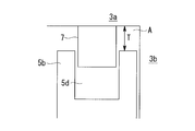
また、接触位置P1にあるときに、接触する壁体3b,5b間において歯先と歯底のチップクリアランスTが最も小さくなるので、壁体3bの渦巻き方向の漏れを小さくできる。すなわち、図15に示すように、壁体5bの歯先と、チップシール7と、端板3aの歯底と、壁体3bの側面とで囲まれた領域Aが渦巻き方向の漏れ隙間となるが、チップクリアランスTを最小にできるので、壁体3bの渦巻き方向の漏れを小さくできる。なお、符号5dは、壁体5bの先端に形成されたチップシール溝である。
端板傾斜部3a1に、端板傾斜接続部3a5と壁体3bとの交点Cp0を接点とする1つの半円弧を等高線Ct2として形成することとした。そして、端板傾斜接続部3a5に対して、壁体傾斜接続部5b5が、旋回運動時の渦巻き方向における旋回中央位置(接触位置P1)で一致するように、すなわち同位相となるように配置すれば、旋回運動時に歯先と歯底が干渉することがなく、チップクリアランスを可及的に小さくできる。
また、接触位置P1にあるときに、接触する壁体3b,5b間において歯先と歯底のチップクリアランスTが最も小さくなるので、壁体3bの渦巻き方向の漏れを小さくできる。すなわち、図15に示すように、壁体5bの歯先と、チップシール7と、端板3aの歯底と、壁体3bの側面とで囲まれた領域Aが渦巻き方向の漏れ隙間となるが、チップクリアランスTを最小にできるので、壁体3bの渦巻き方向の漏れを小さくできる。なお、符号5dは、壁体5bの先端に形成されたチップシール溝である。
[第3実施形態]
次に、本発明の第3実施形態について説明する。本実施形態は、第2実施形態に対して図12に示した端板傾斜接続部3a5周りの形状が異なり、その他の構成は第2実施形態と同様である。したがって、第2実施形態との相違点について説明し、同様の構成については同一符号を付しその説明を省略する。
次に、本発明の第3実施形態について説明する。本実施形態は、第2実施形態に対して図12に示した端板傾斜接続部3a5周りの形状が異なり、その他の構成は第2実施形態と同様である。したがって、第2実施形態との相違点について説明し、同様の構成については同一符号を付しその説明を省略する。
第2実施形態では等高線Ct2が1つの半円弧とされていたが、本実施形態では等高線が2つの同径の円弧とされている点で相違する。
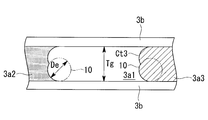
2つの円弧とされた等高線を端板傾斜部3a1,5a1に形成するには、図16に示すように、エンドミル10での加工によって行う。図16は、図11(a)に対応する図であり、エンドミル10を壁体3b,5b渦巻き方向に傾斜を上るように2回切削する(2パス)ことによって加工する。すなわち、1回目の切削で片方の壁体3bの側壁とこれに連なる歯底を加工し、2回目の切削で他方の壁体3bの側壁とこれに連なる歯底を加工する。これにより、2つの半円弧が幅中央にて接続された形状が等高線Ct3となる。
したがって、本実施形態では、(エンドミル直径De<歯底幅Tg)という関係になる。
したがって、本実施形態では、(エンドミル直径De<歯底幅Tg)という関係になる。
図17には、上述した加工法によって得られた円弧とされた等高線Ct3が示されている。同図は、第2実施形態の図12に対応する図である。
図17に示されているように、等高線Ct3は、エンドミル直径Deを直径とした二つの円弧が歯底の幅中央で接続された形状となっており、各円弧は端板傾斜部3a1側(同図において左側)に凸とされている。等高線Ct3は、壁体3bの内側3b-inと端板傾斜接続部3a5との交点Cp0と、壁体3bの外側3b-outと端板傾斜接続部3a5との交点Cp0とを接点としている。
図17に示されているように、等高線Ct3は、エンドミル直径Deを直径とした二つの円弧が歯底の幅中央で接続された形状となっており、各円弧は端板傾斜部3a1側(同図において左側)に凸とされている。等高線Ct3は、壁体3bの内側3b-inと端板傾斜接続部3a5との交点Cp0と、壁体3bの外側3b-outと端板傾斜接続部3a5との交点Cp0とを接点としている。
壁体5bの壁体傾斜接続部5b5は、接触位置P1にて、旋回運動時の渦巻き方向(図17において左右方向)における旋回中央位置で一致するように配置されている。すなわち、壁体傾斜接続部5b5と端板傾斜接続部3a5とを同位相としている。その理由は、第2実施形態にて説明したように、歯先と歯底が接触せず、かつチップクリアランスを可及的に小さくするためである。
旋回軌跡Trの中心O3から、渦巻き方向でかつ傾斜部3a1方向における等高線Ct3までの距離Rが旋回半径ρよりも小さくなると歯底と歯先が干渉することになるので、下式を満たすことが必要である。
{Tg2+(2ρ)2}/(2Tg)≦De≦Tg ・・・(2)
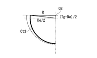
なお、距離Rは、図18の幾何学関係を参照すれば、下式で表される。
R=(1/2)×{De2-(Tg-De)2}1/2 ・・・(3)
{Tg2+(2ρ)2}/(2Tg)≦De≦Tg ・・・(2)
なお、距離Rは、図18の幾何学関係を参照すれば、下式で表される。
R=(1/2)×{De2-(Tg-De)2}1/2 ・・・(3)
また、本実施形態では、第2実施形態に比べて、壁体5bが幅中央位置P2に進んだ場合のチップクリアランスが小さくなるので有利である。なぜなら、図17を見れば明らかなように、旋回軌跡Trの中心O3から等高線Ct3までの距離Rは、第2実施形態の対応する距離Tg/2(図12参照)よりも短くなるからである。
チップクリアランスを最も小さくするためには、距離Rが旋回半径ρに等しくする。R=ρを上式(3)に代入して解くと、下式が導かれる。
De={Tg2+(2ρ)2}/(2Tg) ・・・(4)
すなわち、上式を満たすようにエンドミル直径Deで形成される等高線Ct3とすれば良い。
De={Tg2+(2ρ)2}/(2Tg) ・・・(4)
すなわち、上式を満たすようにエンドミル直径Deで形成される等高線Ct3とすれば良い。
本実施形態によれば、第2実施形態の作用効果に加えて、以下の作用効果を奏する。
等高線Ct3を2つの円弧で構成することとしたので、距離RをTg/2よりも短くできるので、第2実施形態に比べてチップクリアランスを小さくして漏れを小さくすることができる。
等高線Ct3を2つの円弧で構成することとしたので、距離RをTg/2よりも短くできるので、第2実施形態に比べてチップクリアランスを小さくして漏れを小さくすることができる。
また、式(4)を満たすようなエンドミル直径Deを有する2つの円弧で等高線Ct3を形成することで、旋回運動時に歯先と歯底が最も近づいたときに等高線Ct3と壁体傾斜接続部5b5と間におけるチップクリアランスをゼロに近づけることができる。
なお、本実施形態では、2つの同径の円弧から構成された等高線Ct3としたが、3つ以上の円弧から構成された等高線としてもよい。
また、上述した各実施形態では、平坦部3a2,3a3,3b2,3b3,5a2,5a3,5b2,5b3を有する構成としたが、最外周側および/または最内周側に平坦部を備えていない構成に対しても適用できる。例えば、第1実施形態の場合には、固定スクロール3と旋回スクロール5とを、対向する傾斜部同士が遠ざかる方向に旋回半径分だけ位相をずらして配置する。第2実施形態や第3実施形態の場合には、固定スクロール3と旋回スクロール5とを、旋回運動時の渦巻き方向における旋回中央位置で一致する位相となるように配置する。
また、上述した各実施形態では、スクロール圧縮機として説明したが、膨張機として用いるスクロール膨張機に対しても本発明を適用することができる。
1 スクロール圧縮機(スクロール流体機械)
3 固定スクロール(第1スクロール部材)
3a 端板(第1端板)
3a1 端板傾斜部
3a2 端板平坦部(内周側)
3a3 端板平坦部(外周側)
3a4 端板傾斜接続部(内周側)
3a5 端板傾斜接続部(外周側)
3b 壁体(第1壁体)
3b1 壁体傾斜部
3b2 壁体平坦部(内周側)
3b3 壁体平坦部(外周側)
3b4 壁体傾斜接続部(内周側)
3b5 壁体傾斜接続部(外周側)
3c 吐出ポート
5 旋回スクロール(第2スクロール部材)
5a 端板(第2端板)
5a1 端板傾斜部
5a2 端板平坦部(内周側)
5a3 端板平坦部(外周側)
5b 壁体(第2壁体)
5b1 壁体傾斜部
5b2 壁体平坦部(内周側)
5b3 壁体平坦部(外周側)
5b4 壁体傾斜接続部(内周側)
5b5 壁体傾斜接続部(外周側)
5d チップシール溝
7 チップシール
10 エンドミル
Ct1,Ct2,Ct3 等高線
L 対向面間距離
T チップクリアランス
Tg 歯底幅
Tr 旋回軌跡
W1 壁体の中心線
φ 傾き
3 固定スクロール(第1スクロール部材)
3a 端板(第1端板)
3a1 端板傾斜部
3a2 端板平坦部(内周側)
3a3 端板平坦部(外周側)
3a4 端板傾斜接続部(内周側)
3a5 端板傾斜接続部(外周側)
3b 壁体(第1壁体)
3b1 壁体傾斜部
3b2 壁体平坦部(内周側)
3b3 壁体平坦部(外周側)
3b4 壁体傾斜接続部(内周側)
3b5 壁体傾斜接続部(外周側)
3c 吐出ポート
5 旋回スクロール(第2スクロール部材)
5a 端板(第2端板)
5a1 端板傾斜部
5a2 端板平坦部(内周側)
5a3 端板平坦部(外周側)
5b 壁体(第2壁体)
5b1 壁体傾斜部
5b2 壁体平坦部(内周側)
5b3 壁体平坦部(外周側)
5b4 壁体傾斜接続部(内周側)
5b5 壁体傾斜接続部(外周側)
5d チップシール溝
7 チップシール
10 エンドミル
Ct1,Ct2,Ct3 等高線
L 対向面間距離
T チップクリアランス
Tg 歯底幅
Tr 旋回軌跡
W1 壁体の中心線
φ 傾き
Claims (6)
- 第1端板上に渦巻状の第1壁体が設けられた第1スクロール部材と、
前記第1端板に向かい合うように配置された第2端板上に渦巻状の第2壁体が設けられ、該第2壁体が前記第1壁体と旋回半径分だけオフセットされて噛み合って相対的に公転旋回運動を行う第2スクロール部材と、
を備えたスクロール流体機械であって、
向かい合う前記第1端板と前記第2端板との対向面間距離が、前記第1壁体及び前記第2壁体の外周側から内周側に向かって、連続的に減少する傾斜部が設けられ、
前記第1壁体および前記第2壁体の少なくともいずれか一方は、前記傾斜部を形成するように外周側から内周側に向かって該壁体の高さが連続的に減少する壁体傾斜部を有し、
前記第1端板および前記第2端板の少なくともいずれか一方は、前記壁体傾斜部の歯先に対向する歯底面が該壁体傾斜部の傾斜に応じて傾斜する端板傾斜部を有し、
前記端板傾斜部には、前記壁体の渦巻き方向に直交する方向に等高線が形成され、
前記第1スクロール部材と前記第2スクロール部材とが、対向する前記傾斜部同士が遠ざかる方向に前記旋回半径分だけ位相がずらされて配置されているスクロール流体機械。 - 前記第1壁体および前記第2壁体の最外周部および/または最内周部には、高さが変化しない壁体平坦部が設けられ、
前記第1端板および前記第2端板には、前記壁体平坦部に対応した端板平坦部が設けられ、
前記端板傾斜部と前記端板平坦部とが接続される端板傾斜接続部に対して、前記壁体傾斜部と前記壁体平坦部とが接続される壁体傾斜接続部が、前記旋回半径分だけ位相が遅れて配置されている請求項1に記載のスクロール流体機械。 - 第1端板上に渦巻状の第1壁体が設けられた第1スクロール部材と、
前記第1端板に向かい合うように配置された第2端板上に渦巻状の第2壁体が設けられ、該第2壁体が前記第1壁体と旋回半径分だけオフセットされて噛み合って相対的に公転旋回運動を行う第2スクロール部材と、
を備えたスクロール流体機械であって、
向かい合う前記第1端板と前記第2端板との対向面間距離が、前記第1壁体及び前記第2壁体の外周側から内周側に向かって、連続的に減少する傾斜部が設けられ、
前記第1壁体および前記第2壁体の少なくともいずれか一方は、前記傾斜部を形成するように外周側から内周側に向かって該壁体の高さが連続的に減少する壁体傾斜部を有し、
前記第1端板および前記第2端板の少なくともいずれか一方は、前記壁体傾斜部の歯先に対向する歯底面が該壁体傾斜部の傾斜に応じて傾斜する端板傾斜部を有し、
前記端板傾斜部には、前記壁体との交点を接点とする1又は複数の円弧が等高線として形成され、
前記第1スクロール部材と前記第2スクロール部材とが、前記旋回運動時の渦巻き方向における旋回中央位置で一致する位相となるように配置されているスクロール流体機械。 - 前記第1壁体および前記第2壁体の最外周部および/または最内周部には、高さが変化しない壁体平坦部が設けられ、
前記第1端板および前記第2端板には、前記壁体平坦部に対応した端板平坦部が設けられ、
前記端板傾斜部には、該端板傾斜部と前記端板平坦部とが接続される端板傾斜接続部と前記壁体との交点を接点とする1又は複数の円弧が等高線として形成され、
前記端板傾斜接続部に対して、前記壁体傾斜部と前記壁体平坦部とが接続される壁体傾斜接続部が、前記旋回運動時の渦巻き方向における旋回中央位置で一致するように配置されている請求項3に記載のスクロール流体機械。 - 前記等高線を形成する円弧の直径をDeとし、前記端板傾斜部の歯底幅をTg、旋回運動の旋回半径をρとした場合に、
{Tg2+(2ρ)2}/(2Tg)≦De≦Tg
とされている請求項3又は4に記載のスクロール流体機械。 - De={Tg2+(2ρ)2}/(2Tg)とされている請求項5に記載のスクロール流体機械。
Applications Claiming Priority (2)
| Application Number | Priority Date | Filing Date | Title |
|---|---|---|---|
| JP2016161206A JP6382265B2 (ja) | 2016-08-19 | 2016-08-19 | スクロール流体機械 |
| JP2016-161206 | 2016-08-19 |
Publications (1)
| Publication Number | Publication Date |
|---|---|
| WO2018034272A1 true WO2018034272A1 (ja) | 2018-02-22 |
Family
ID=61197305
Family Applications (1)
| Application Number | Title | Priority Date | Filing Date |
|---|---|---|---|
| PCT/JP2017/029323 Ceased WO2018034272A1 (ja) | 2016-08-19 | 2017-08-14 | スクロール流体機械 |
Country Status (2)
| Country | Link |
|---|---|
| JP (1) | JP6382265B2 (ja) |
| WO (1) | WO2018034272A1 (ja) |
Families Citing this family (2)
| Publication number | Priority date | Publication date | Assignee | Title |
|---|---|---|---|---|
| JP7413040B2 (ja) * | 2018-02-21 | 2024-01-15 | 三菱重工サーマルシステムズ株式会社 | スクロール流体機械及びその設計方法 |
| JP6686055B2 (ja) * | 2018-02-21 | 2020-04-22 | 三菱重工サーマルシステムズ株式会社 | スクロール流体機械 |
Citations (1)
| Publication number | Priority date | Publication date | Assignee | Title |
|---|---|---|---|---|
| JP2002070766A (ja) * | 2000-08-28 | 2002-03-08 | Mitsubishi Heavy Ind Ltd | スクロール圧縮機 |
-
2016
- 2016-08-19 JP JP2016161206A patent/JP6382265B2/ja active Active
-
2017
- 2017-08-14 WO PCT/JP2017/029323 patent/WO2018034272A1/ja not_active Ceased
Patent Citations (1)
| Publication number | Priority date | Publication date | Assignee | Title |
|---|---|---|---|---|
| JP2002070766A (ja) * | 2000-08-28 | 2002-03-08 | Mitsubishi Heavy Ind Ltd | スクロール圧縮機 |
Also Published As
| Publication number | Publication date |
|---|---|
| JP2018028301A (ja) | 2018-02-22 |
| JP6382265B2 (ja) | 2018-08-29 |
Similar Documents
| Publication | Publication Date | Title |
|---|---|---|
| WO2018043359A1 (ja) | スクロール流体機械およびチップシール | |
| JP6336534B2 (ja) | スクロール流体機械およびスクロール部材の加工方法 | |
| JP6382265B2 (ja) | スクロール流体機械 | |
| JP7413040B2 (ja) | スクロール流体機械及びその設計方法 | |
| JP6686055B2 (ja) | スクロール流体機械 | |
| WO2019163323A1 (ja) | スクロール流体機械 | |
| JP6689898B2 (ja) | スクロール流体機械およびこれに用いられるスクロール部材 | |
| JP6386144B1 (ja) | スクロール流体機械 | |
| JP6336530B2 (ja) | スクロール流体機械およびこれに用いられるスクロール部材 | |
| JP6336531B2 (ja) | スクロール流体機械 | |
| JP6325035B2 (ja) | スクロール流体機械 | |
| JP6336535B2 (ja) | スクロール流体機械およびスクロール部材の加工方法 | |
| JP6679634B2 (ja) | スクロール部材の加工方法 | |
| WO2018034255A1 (ja) | スクロール流体機械 | |
| JP6505906B2 (ja) | スクロール流体機械 | |
| JP6612376B2 (ja) | スクロール流体機械 |
Legal Events
| Date | Code | Title | Description |
|---|---|---|---|
| 121 | Ep: the epo has been informed by wipo that ep was designated in this application |
Ref document number: 17841494 Country of ref document: EP Kind code of ref document: A1 |
|
| NENP | Non-entry into the national phase |
Ref country code: DE |
|
| 122 | Ep: pct application non-entry in european phase |
Ref document number: 17841494 Country of ref document: EP Kind code of ref document: A1 |