WO2018034258A1 - 内包フラーレン生成装置及び生成方法 - Google Patents
内包フラーレン生成装置及び生成方法 Download PDFInfo
- Publication number
- WO2018034258A1 WO2018034258A1 PCT/JP2017/029247 JP2017029247W WO2018034258A1 WO 2018034258 A1 WO2018034258 A1 WO 2018034258A1 JP 2017029247 W JP2017029247 W JP 2017029247W WO 2018034258 A1 WO2018034258 A1 WO 2018034258A1
- Authority
- WO
- WIPO (PCT)
- Prior art keywords
- fullerene
- substance
- endohedral
- inclusion
- encapsulated
- Prior art date
- Legal status (The legal status is an assumption and is not a legal conclusion. Google has not performed a legal analysis and makes no representation as to the accuracy of the status listed.)
- Ceased
Links
Images



Classifications
-
- C—CHEMISTRY; METALLURGY
- C01—INORGANIC CHEMISTRY
- C01B—NON-METALLIC ELEMENTS; COMPOUNDS THEREOF; METALLOIDS OR COMPOUNDS THEREOF NOT COVERED BY SUBCLASS C01C
- C01B32/00—Carbon; Compounds thereof
- C01B32/15—Nano-sized carbon materials
- C01B32/152—Fullerenes
- C01B32/154—Preparation
Definitions
- the present invention relates to an endohedral fullerene production apparatus and production method for producing an endohedral fullerene in which various substances are encapsulated in the internal space of the fullerene.
- the C 60 fullerene is produced at the highest rate when the fullerene is produced.
- the endohedral fullerene in which metal and non-metallic atoms, molecules, and ions are encapsulated in this space does not exist in the conventional fullerene (semiconductor characteristics, superconductivity) Such as physical properties, spin properties, and magnetism) and is expected as a novel functional material.
- a physical method such as an arc discharge method, a laser evaporation method, a high frequency discharge method, a high temperature and high pressure treatment method, and a chemical method have been proposed. Specifically, the following manufacturing methods have been proposed.
- nitrogen ions and nitrogen molecular ions are generated by plasma discharge using nitrogen gas as a raw material, and the negative ions are applied to the fullerene deposition substrate to apply the negative ions and the nitrogen ions.
- a method of generating nitrogen-containing fullerene by accelerating molecular ions toward the deposition substrate and colliding with the fullerene see Patent Documents 2 and 3.
- the generation rate remains at 1% or less, and the generation rate is still low.
- the substance to be included in the fullerene by this proposal is limited to nitrogen ions and nitrogen molecular ions, and there is a problem that it is difficult to adapt to various substances.
- a high bias voltage is applied to nickel metal and an electron beam is irradiated to generate nickel plasma, and a negative bias voltage is applied to the substrate on which fullerene is deposited to apply the nickel metal.
- a method of generating nickel-encapsulated fullerene by accelerating only nickel ions in plasma toward the substrate and colliding with the fullerene has been proposed (see Patent Document 4).
- a filament power source 500 W and a beam power source 1000 W bias voltage 5 k ⁇ , emission current 200 mA
- metallocene ferrocene or the like
- oxidation treatment or visible light treatment is performed.
- fullerene encapsulating metallocene and heating it in vacuum to decompose the metallocene in the fullerene to produce fullerene in which magnetic metal atoms are encapsulated as a decomposition product has been proposed (see Patent Document 5).
- the present invention solves the above-described problems in the prior art, and can include a wide variety of substances, and an endohedral fullerene generation apparatus and a generation method capable of generating an endohedral fullerene that encapsulates the substance in fullerene efficiently and energy-saving. It is an issue to provide.
- a fullerene diffusing portion having an encapsulating material support portion that supports a solid encapsulating material, a crucible into which solid fullerene is introduced, and a heating portion that heats the crucible to dissipate a fullerene sublimate from the crucible.
- a fullerene deposition substrate for depositing the fullerene sublimation body diffused from the fullerene radiation portion as a fullerene deposition body, and the inclusion substance in the inclusion substance while being ablated by irradiating the inclusion substance with laser light
- the laser beam irradiated from the laser beam irradiation unit disposed outside is disposed inside the substrate.
- a vacuum vessel in which a window portion that can be introduced toward the packaging material support portion is formed, diffused in ablated state, and the kinetic energy is controlled in the fullerene An endohedral fullerene generating apparatus, wherein the endohedral fullerene is produced by bringing the fullerene into contact with at least one of a sublimation body and the fullerene deposit and encapsulating the fullerene.
- the fullerene deposition substrate includes a cooling unit that promotes a phase change of the fullerene sublimate to a solid phase.
- ⁇ 3> The endohedral fullerene generation device according to any one of ⁇ 1> to ⁇ 2>, wherein the crucible in the fullerene diffusion unit includes a guide tube that diffuses the fullerene sublimate toward the fullerene deposition substrate.
- the guide tube has a tapered structure that is expanded from the proximal end side toward a distal end side that diffuses the fullerene sublimate.
- ⁇ 5> The endohedral fullerene generation device according to any one of ⁇ 1> to ⁇ 4>, wherein the crucible in the fullerene diffusion portion has a mesh structure in a diffusion path for diffusing the fullerene sublimation body from the inside to the outside.
- ⁇ 6> The endohedral fullerene according to any one of ⁇ 1> to ⁇ 5>, wherein the fullerene deposition substrate includes an electrode portion formed of an electrode material, and a voltage applying unit that applies a voltage to the electrode portion is disposed. Generator.
- ⁇ 7> The endohedral fullerene generator according to any one of ⁇ 1> to ⁇ 6>, wherein a microwave introduction unit that introduces a microwave into the encapsulating substance diffused in the ablated state is disposed in the vacuum container.
- a gas introduction unit that introduces a gas toward the encapsulating substance diffused in an ablated state is formed in the vacuum container.
- An auxiliary laser irradiation unit for irradiating auxiliary laser light to the inclusion substance diffused in the ablation state to make the bulk particles in the inclusion substance fine particles is arranged outside the vacuum container, ⁇ 1> to ⁇ 1> in which a window portion is formed in the vacuum vessel that allows the auxiliary laser light irradiated from the auxiliary laser light irradiation portion to be introduced toward the inclusion substance diffused in the ablated state.
- the magnetic field generation unit that enables control of the diffusion trajectory of the charged particles in the inclusion material diffused in the ablation state is disposed in the vacuum vessel. Encapsulated fullerene generator.
- a fullerene sublimation process in which solid fullerene is heated to generate a fullerene sublimate, and the solid inclusion substance is irradiated with laser light to be ablated, and the fullerene is applied to the inclusion substance in the inclusion substance.
- a laser beam irradiation process in which the irradiation energy of the laser beam is controlled so as to give all or a part of the kinetic energy included in the substrate, and a fullerene deposition process in which the fullerene sublimation body is deposited on a fullerene deposition substrate as a fullerene deposition body
- the inclusion material diffused in the ablation state and controlled in kinetic energy is brought into contact with at least one of the fullerene sublimate and the fullerene deposit, and the inclusion material is included in the fullerene.
- ⁇ 12> The endohedral fullerene generation method according to ⁇ 11>, further including a voltage application step of applying a voltage to the fullerene deposition substrate.
- ⁇ 13> The method for producing an endohedral fullerene according to any one of ⁇ 11> to ⁇ 12>, further including a microwave introduction step of introducing a microwave into the encapsulating substance diffused in the ablation state.
- the above-mentioned problems in the prior art can be solved, a wide variety of substances can be included, and an endohedral fullerene that can efficiently generate an endohedral fullerene that encapsulates the substance in the fullerene is energy-saving.
- a generation device and a generation method can be provided.
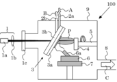
- FIG. 1 is an explanatory diagram showing a schematic configuration of an endohedral fullerene generator according to the first embodiment of the present invention.
- the endohedral fullerene generating apparatus 100 mainly includes a laser beam irradiation unit 1, a fullerene deposition substrate 3, an encapsulating substance support unit 5, a crucible 6, a heating unit 7, and a vacuum vessel 9.
- the laser beam irradiation unit 1 irradiates the encapsulating substance 4 with laser light to ablate, and applies all or part of the kinetic energy to be included in the fullerene to the encapsulated substance in the encapsulating substance 4.
- the irradiation energy of the laser beam is controlled so that all of the kinetic energy is applied to the inclusion substance 4.
- a mixed rod of carbon and metal is used as a raw material for inclusion fullerene, and the metal inclusion fullerene in which the metal is included by chance by irradiating it with laser light and evaporating it. Is supposed to be generated.
- the irradiation energy of the laser beam is controlled so as to give the kinetic energy to the encapsulating substance, so that the endohedral substance encapsulates the fullerene. It is assumed that the kinetic energy suitable for the application is applied, and the inclusion substance is intentionally included in the fullerene. In the present specification, “effectively generating an endohedral fullerene” means that the kinetic energy suitable for encapsulating the endohedral substance in the fullerene is controlled by controlling the irradiation energy of the laser beam. It means that the substance for inclusion 4 is included in the fullerene in the applied state.
- the kinetic energy suitable for inclusion in the fullerene can be obtained by quantum molecular dynamics calculation. Specifically, by using the Born-Openheimer adiabatic approximation, by solving the wave function for the carbon having a ground canonical distribution that moves around the carbon nucleus in the fullerene and the encapsulated substance nucleus given the initial energy, Find the equilibrium state of the system. At this time, the Hamiltonian H of the electron is represented by the following formula (1).
- m e denotes the mass of the electron
- e indicates the electron charge
- [rho is the electron charge density
- R represents the position of the electron
- r ′ represents the distance from the electron
- Z represents the number of charges of the electron
- n represents a label identifying the atom in the nucleus
- R n represents the distance from the n nucleus
- ⁇ represents the Kronecker delta
- F xc represents the exchange correlation function.
- the formula (2), the N in (3), indicates the total number of electrons
- k B denotes the Boltzmann constant
- T represents the temperature of the considered systems
- epsilon i is the eigenvalue of the Hamiltonian H
- ⁇ i represents the eigenfunction of the Hamiltonian H.
- the initial energy of the inclusion substance (kinetic energy for inclusion) is changed, and each of the changed values is changed.
- the final system state at each initial energy is determined by numerically solving the equations (1) to (3).
- the initial energy of the inclusion substance is changed, and in the final equilibrium state, the inclusion substance is changed into the fullerene by examining the boundary between the energy contained in the fullerene and the energy not contained.
- the kinetic energy required for inclusion in fullerene is required.
- the following reference 1 can be referred about the said method. Reference 1: K. Ohno, Y. Maruyama, and Y. Kawazoe, Physical Review B, vol. 53, No. 7, pp. 4078-4082 (1996)
- the laser light irradiation unit 1 includes, for example, a laser light source 1a and a condensing lens 1b as illustrated.
- a laser light source 1a and a condensing lens 1b As illustrated.
- the laser beam it becomes easy to control the irradiation energy for imparting the kinetic energy suitable for inclusion to the inclusion substance, and greatly compared to the case of using a conventional electron beam. Energy saving can be achieved. That is, the kinetic energy can be imparted to the inclusion substance 4 easily and energy-saving simply by adjusting the output of the laser light source 1a and the focal length of the lens 1b.
- the laser light source 1a and the lens 1b are not particularly limited, and can be appropriately selected from known laser devices used in laser ablation devices and the like.
- Examples of the laser light source 1a that can be suitably used include a pulse laser.
- the pulse laser is not particularly limited, but has a laser energy (laser output) of 1,000 mJ / pulse or less, an operation repetition frequency of 1 Hz to 1,000 Hz, and a pulse width of 6 ns to 150 ns. preferable.
- the pulse laser satisfying these conditions it is easy to generate the kinetic energy band suitable for the inclusion of the inclusion substance by optimizing the laser energy density, and the position of the lens 1b as the condenser lens is adjusted. Then, by optimizing the laser beam irradiation area, the endohedral fullerene can be generated with a high generation rate of 4.5% or more.
- the production rate of the endohedral fullerene is defined as follows. That is, after generating the endohedral fullerene using the endohedral fullerene generator, the sediment collected from the endohedral fullerene generator is measured using a time-of-flight mass spectrometer (TOF-MASS), and A total value of peak intensities of empty fullerenes in which the inclusion substance contained in the deposit is not included and a total value of peak intensities of the inclusion fullerenes in which the inclusion substance is included are calculated. Based on these calculation results, the generation rate is given by the following equation (4).
- TOF-MASS time-of-flight mass spectrometer
- the production rate is defined as follows by the electron spin resonance method and the UV / vis absorption spectrum method. That is, after generating the endohedral fullerene using the endohedral fullerene generator, the deposit recovered from the endohedral fullerene generator includes impurities such as the empty fullerene and heterofullerene in addition to the endohedral fullerene. . The deposit is put into a solvent such as toluene and separated into one that is soluble in the solvent and one that is not soluble.
- the impurities are separated from the empty fullerene and the endohedral fullerene by using one kind or two or more kinds of solvents.
- the empty fullerene and the endohedral fullerene are dissolved in the separated solvent.
- the sample dissolved in the solvent is analyzed by the electron spin resonance method, and the intensity is obtained from the signal corresponding to the unpaired electrons of the inclusion substance.
- a graph representing the relationship between the signal intensity obtained by the electron spin resonance method and the molar concentration is prepared in advance using a reagent capable of creating a state having an unpaired electron of the inclusion substance.
- the molar concentration (mol / L) of the endohedral fullerene is calculated by comparing the signal intensity with the graph.
- the UV / vis absorption spectrum method is performed on the sample dissolved in the solvent, and the molar concentration of the empty fullerene is calculated from the absorption intensity of the visible absorption spectra 221 nm, 271 nm, and 347 nm absorbed by the fullerene. Is done. Based on these calculation results, the production rate when a substance having unpaired electrons is included in the fullerene is given by the following formula (5).
- c Cn + M @ Cn represents the molar concentration of the empty fullerene in the solvent calculated by the UV / vis absorption spectrum method
- c M @ Cn represents the electron spin.
- the molar concentration of the endohedral fullerene in the solvent calculated by a resonance method is shown.
- Reference 4 S. Kazaoui, R. Ross and N. Minami, Solid State Commun., 90, 623 (1994)
- the fullerene deposition substrate 3 deposits a fullerene sublimation body diffused from the crucible 6 (fullerene diffusion portion) as a fullerene deposition body.
- the deposition plate 3a and the cooling plate 3b are bonded together.
- the material for forming the deposition plate 3a and the cooling plate 3b is not particularly limited as long as it has necessary heat resistance, and a known substrate material can be used.
- a through hole for allowing the laser beam irradiated from the laser beam irradiation unit 1 toward the inclusion material 4 to pass through the fullerene deposition substrate 3 (deposition plate 3a and cooling plate 3b) is formed. .
- the cooling plate 3b serves as a cooling unit that promotes the phase change of the fullerene sublimate to a solid phase. That is, as the cooling plate 3b, for example, there is a circulation path for the coolant introduced and discharged from the coolant introduction pipe 2a and the coolant discharge pipe 2b through the paths of arrows A and B, and cooling control is possible. Is done. By such cooling control, the fullerene sublimate diffused in the vacuum vessel 9 can be effectively deposited by being adsorbed on the deposition plate 3a.
- the coolant any liquid such as water or gas can be used.
- one end side is connected to a known cooling device (not shown) that controls the temperature of the coolant such as a chiller, and the other end side cooling plate 3b It also serves to stably support the fullerene deposition substrate 3 in the vacuum vessel 9 through the connection.
- a known cooling device not shown
- the other end side cooling plate 3b It also serves to stably support the fullerene deposition substrate 3 in the vacuum vessel 9 through the connection.
- the inclusion material support 5 is configured so that the solid inclusion material 4 is supported, and can be configured, for example, in the same manner as a target material support in a known vapor deposition apparatus.
- it is configured as a support column that can be rotationally driven.
- the inclusion substance 4 may be the inclusion substance itself to be included in the fullerene, or a substance partially containing the inclusion substance to be included in the fullerene (for example, a compound containing an atom as the inclusion substance) Etc.). In the latter case, by providing the kinetic energy peculiar to the inclusion substance, the inclusion substance can be selectively included in the fullerene by selecting from other substances not intended for inclusion.
- the fullerene deposition substrate 3 is arranged in the direction of the plume P diffusion, and the fullerene deposit on the fullerene deposition substrate 3 (including fullerene adsorbed in a gaseous state and fullerene that is solidified by cooling) and the above
- the fullerene sublimate in the vicinity of the fullerene deposition substrate 3 is caused to collide with the plume P, and the substance to which the kinetic energy is applied is included in the fullerene.
- the distance between the fullerene deposition substrate 3 and the inclusion substance 4 is preferably short, and for example, the shortest distance is preferably 20 mm to 70 mm.
- the fullerene diffusing unit includes a crucible 6 into which the solid fullerene is introduced, and a heating unit 7 that heats the crucible 6 to dissipate the fullerene sublimate from the crucible 6.
- a heating unit 7 that heats the crucible 6 to dissipate the fullerene sublimate from the crucible 6.
- the fullerene introduced into the crucible 6 for example, commercially available fullerene powder can be used.
- the heating temperature of the crucible 6 in the heating unit 7 is not particularly limited, but is preferably 750 ° C. to 1,000 ° C.
- the crucible 6 is not particularly limited and can be the same as the crucible used in a known heating device.
- the fullerene deposition substrate 3 is disposed on the axial extension of the tube, It is preferable to have a guide tube 6 a for diffusing the fullerene sublimate toward the fullerene deposition substrate 3.
- a guide tube 6 a By having such a guide tube 6 a, the fullerene sublimation body can be prevented from being dissipated to the outside of the fullerene deposition substrate 3.
- the distance between the fullerene deposition substrate 3 and the crucible 6 (a discharge port of the guide tube 6a) is short for the purpose of suppressing the fullerene sublimation body from escaping to the outside of the fullerene deposition substrate 3.
- the shortest distance is preferably 20 mm to 100 mm.
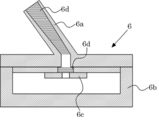
- the crucible 6 is not particularly limited, but preferably has all or part of the features shown in FIG.
- FIG. 2 is a cross-sectional view for explaining a preferred configuration example of the crucible. That is, the fullerene sublimate diffused from the crucible 6 may exhibit an unstable behavior such as bumping at the time of a sudden phase change from a solid, and such behavior is related to the fullerene sublimation toward the fullerene deposition substrate 3. In addition to the excessive amount of the body, the non-sublimated powder of the fullerene scatters to the outside of the crucible 6 as it is, which causes a decrease in controllability of the sublimation amount. Therefore, as shown in FIG.
- the pressure in the accommodating portion 6 is adjusted by adjusting the opening diameter.
- the mesh structure 6d is formed in the lid portion 6c with an opening that suppresses bumping of the sublimation body, and further in the diffusion path that diffuses the fullerene sublimation body from the inside to the outside.
- the mesh material for forming the mesh structure 6d is not particularly limited as long as it has necessary heat resistance, and can be appropriately selected from known materials.
- the guide tube 6a has a taper structure that is expanded from the base end side that is the accommodating portion 6b side toward the distal end side that dissipates the fullerene sublimation body.
- the guide tube 6a has a taper structure that is expanded from the base end side that is the accommodating portion 6b side toward the distal end side that dissipates the fullerene sublimation body.
- the vacuum container 9 is configured so that the deposition substrate 3, the inclusion material support 5, the crucible 6, and the heating unit 7 are disposed inside, and the laser irradiated from the laser light irradiation unit 1 disposed outside.
- a window portion 1c through which light can be introduced toward the inclusion substance 4 and an exhaust portion 8 for adjusting the internal pressure by exhaust (in the direction of arrow C) are formed (see FIG. 1).
- the vacuum vessel 9 can be configured using a known vacuum vessel.
- the pressure (background vacuum) in the container during the endohedral fullerene production process is not particularly limited, and is, for example, 1.0 ⁇ 10 ⁇ 5 Pa to 1 Pa.
- the endohedral fullerene can be generated by the following operation. First, heating is performed by the heating unit 7 in a state where the fullerene is introduced into the crucible 6 to generate the fullerene sublimate (fullerene sublimation step). Further, the encapsulating substance 4 is ablated by irradiation with the laser light. At this time, the irradiation with the laser light controls the irradiation energy of the laser light so as to give all or a part (in this example, all) of the kinetic energy included in the fullerene to the inclusion substance. (Laser beam irradiation process).
- the fullerene sublimate is deposited on the fullerene deposition substrate 3 as the fullerene deposit (fullerene deposition step). This operation is performed by placing the fullerene deposition substrate 3 at the diffusion destination of the generated fullerene sublimate. Further, the inclusion material 4 which is diffused in the ablation state and whose kinetic energy is controlled is brought into contact with at least one of the fullerene sublimate and the fullerene deposit, and the inclusion material is included in the fullerene. Fullerenes are generated (encapsulated fullerene generation step). This operation is performed by placing the fullerene deposition substrate 3 on the diffusion destination of the plume P of the encapsulated substance 4 in the ablated state.
- the inclusion substance contained in the fullerene in the inclusion substance 4 is a sublimation body or a deposit (including fullerene adsorbed in a gaseous state or fullerene in a solid state). Although it is not certain whether it is encapsulated, the encapsulated fullerene is collected as a solid material that is finally deposited on the fullerene deposition substrate 3.
- the endohedral fullerene generation apparatus 100 and the endohedral fullerene generation method using the endohedral fullerene generation apparatus 100 a wide variety of substances can be encapsulated in the fullerene for those that can be ablated by the laser beam. Further, by using the laser beam, energy required for the generation of the endohedral fullerene can be saved, and further, a substance to be encapsulated by controlling the irradiation energy of the laser beam is encapsulated in the endohedral fullerene. Since appropriate kinetic energy is imparted, the endohedral fullerene can be generated with high efficiency.
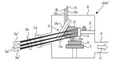
- the endohedral fullerene generation apparatus 100 may be configured using a laser light source including a plurality of laser light sources 1a 'instead of the laser light source 1a as in the endohedral fullerene generation apparatus 100' shown in FIG.
- FIG. 3 is an explanatory diagram for explaining a configuration of a modification of the fullerene generation device according to the first embodiment.
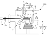
- FIG. 4 is an explanatory diagram showing a schematic configuration of an endohedral fullerene generator according to the second embodiment of the present invention.
- the endohedral fullerene generation apparatus 200 is similar to the endohedral fullerene generation apparatus 100 in that the laser beam irradiation unit 1, the fullerene deposition substrate 3, the internal substance support unit 5, the crucible 6, the heating unit 7, and the vacuum container 9 is different from the endohedral fullerene generator 100 in that it has a bias power supply 10 and a bias application electrode 11.
- explanation of matters common to the endohedral fullerene generation device 100 is omitted, and different matters are explained.
- the deposition plate 3a in the fullerene deposition substrate 3 is formed of an electrode material, and the deposition plate 3a has a role as an electrode unit in addition to the role of depositing the fullerene deposit.
- a bias application electrode 11 is disposed in the vacuum container 9 so as to interpose the inclusion substance 4 as an electrode part that is opposed to the deposition plate 3a.
- the deposition plate 3 a and the bias application electrode 11 are connected to a bias power source 10 as a voltage application unit, and a potential difference is formed between the deposition plate 3 a and the bias application electrode 11 by the voltage applied from the bias power source 10.
- Each of the fullerene deposition substrate 3 (deposition plate 3 a) and the bias application electrode 11 is disposed in a state of being insulated from the vacuum vessel 9.
- the inclusion substance 4 diffused in the ablation state, that is, the plume P includes neutral particles such as atoms and charged particles such as ions. Therefore, it is easy to selectively enclose either the neutral particles or the charged particles in the fullerene by applying a voltage to the fullerene deposition substrate 3 (deposition plate 3a) (voltage application step). That is, by applying a positive or negative bias voltage to the fullerene deposition substrate 3 (deposition plate 3a), only charged particles corresponding to either positive or negative charges are attracted to the fullerene deposition substrate 3 (deposition plate 3a) side.
- the fullerene can be encapsulated, or charged particles corresponding to either positive or negative charge can be repelled to the bias application electrode 11 side so that the remaining particles (neutral particles) can be encapsulated in the fullerene.
- the charged particles When specific charged particles are attracted to the fullerene deposition substrate 3 (deposition plate 3a) and included in the fullerene, the charged particles have kinetic energy that accelerates toward the fullerene deposition substrate 3 (deposition plate 3a). Is granted.
- the acceleration energy of the charged particles accompanying voltage application is controlled, and the fullerene is included in the fullerene
- the kinetic energy is imparted to the charged particles.
- the application condition of the bias voltage is not particularly limited, but is preferably -2,000V to + 2,000V.
- FIG. 5 is an explanatory diagram showing a schematic configuration of an endohedral fullerene generator according to the third embodiment of the present invention.
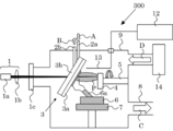
- the endohedral fullerene generating apparatus 300 is similar to the endohedral fullerene generating apparatus 100 in that the laser beam irradiation unit 1, the fullerene deposition substrate 3, the encapsulating substance support unit 5, the crucible 6, the heating unit 7, and the vacuum container.
- the endohedral fullerene generator 100 is different from the endohedral fullerene generator 100 in that it has a microwave supply source 12 and a microwave antenna 13 and a gas supply unit 14 for introducing gas into the vacuum vessel 9 is connected.
- a microwave supply source 12 and a microwave antenna 13 and a gas supply unit 14 for introducing gas into the vacuum vessel 9 is connected.
- explanation of matters common to the endohedral fullerene generation device 100 is omitted, and different matters are explained.
- the microwave supply source 12 is connected to the microwave antenna 13 and supplies microwave energy to the microwave antenna 13.
- the microwave antenna 13 is disposed in the vacuum vessel 9 as a macro wave introducing portion, and introduces the microwave into the inclusion material 4 that is diffused in the ablated state, that is, the plume P.
- the microwave antenna 13 It can select suitably from what is applied to a well-known microwave antenna apparatus, and can use it.
- the inclusion substance 4 diffused in the ablation state that is, the plume P includes particles such as the neutral particles and the charged particles.
- the neutral particles are ionized to form the charged particles (microwave introduction step). Therefore, in the endohedral fullerene generating apparatus 300, the charged particles can be easily included in the fullerene selectively.
- the charged particles can be more easily selectively contained in the fullerene.
- the microwave introduced from the microwave antenna 13 is not particularly limited, and is preferably about 2 GHz to 4 GHz although it depends on the type of substance to be included.
- the gas supply unit 14 is formed in the vacuum vessel 9 as a gas introduction unit, and introduces the gas toward the inclusion substance diffused in the ablated state, that is, the plume P.
- a gas introduction unit there is no restriction
- inert gas such as argon gas
- inert gas can be used.
- the charged particles of the neutral particles accompanying ionization are promoted as compared with the case in an atmosphere containing an impurity gas, and the charged particles are selectively converted into the fullerene.
- a gas supply part 14 it can apply to the inclusion fullerene production
- FIG. 6 is an explanatory diagram showing a schematic configuration of an endohedral fullerene generator according to the fourth embodiment of the present invention.
- the endohedral fullerene generation apparatus 400 is similar to the endohedral fullerene generation apparatus 100 in that the laser beam irradiation unit 1, the fullerene deposition substrate 3, the internal substance support unit 5, the crucible 6, the heating unit 7, and the vacuum container. 9 is different from the endohedral fullerene generator 100 in that the auxiliary laser beam irradiation unit 15 is arranged.
- explanation of matters common to the endohedral fullerene generation device 100 is omitted, and different matters are explained.
- the inclusion material 4 diffused in the ablation state, that is, the plume P may contain coarse bulk particles that are not suitable for inclusion in the fullerene.
- the auxiliary laser light irradiation unit 15 is disposed outside the vacuum vessel 9 and irradiates the plume P with auxiliary laser light to make the bulk particles finer.
- the vacuum vessel 9 can introduce the auxiliary laser emitted from the auxiliary laser light irradiation unit 15 through the window 1c toward the plume P.
- the irradiation energy of the auxiliary laser light emitted from the auxiliary laser light irradiation unit 15 is about 0.1 to 10 times in terms of Joule.
- the auxiliary laser light irradiation unit 15 is not particularly limited, and can be configured by appropriately selecting from known laser equipment used in a laser ablation apparatus or the like.
- symbol 1b 'in a figure shows the lens which condenses.
- FIG. 7 is an explanatory diagram showing a schematic configuration of an endohedral fullerene generator according to the fifth embodiment of the present invention.
- FIG. 7 a mode that the endohedral fullerene production
- a ′ and B ′ in the figure indicate introduction and discharge paths of the coolant with respect to the cooling plate 3b ′. As shown in FIG.
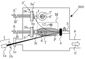
- the endohedral fullerene generation apparatus 500 is similar to the endohedral fullerene generation apparatus 100 in that the laser beam irradiation unit 1, the fullerene deposition substrate 3, the internal substance support unit 5, the crucible 6, the heating unit 7, and the vacuum container. 9, a fullerene deposition substrate 3 ′, a crucible 6 ′, and a heating unit 7 ′ are disposed as the second fullerene deposition substrate and the second fullerene diffusion unit. This is different from the endohedral fullerene generator 100.
- explanation of matters common to the endohedral fullerene generation device 100 is omitted, and different matters are explained.
- the magnetic field generator 17 can control the diffusion trajectory of the charged particles in the inclusion substance 4 that is diffused in the ablation state. That is, the magnetic field M generated by the magnetic field generator 17 makes it possible to separate the diffusion trajectory of the charged particles from the other diffusion trajectories. Therefore, if the fullerene deposition substrate 3 ′, the crucible 6 ′, and the heating unit 7 ′ are disposed as the second fullerene deposition substrate and the second fullerene diffusion unit on the diffusion trajectory of the charged particles, the fullerene Only the charged particles can be selected and included in the fullerene based on the molten particle I on the deposition substrate 3 ′. Further, only the neutral particles can be selected and included in the fullerene based on the particles other than the charged particles on the fullerene deposition substrate 3, that is, the melted particles N of the neutral particles.
- the fullerene deposition substrate 3 ′, the crucible 6 ′, and the heating unit 7 ′ can be configured in the same manner as the fullerene deposition substrate 3, the crucible 6, and the heating unit 7 described in the first embodiment.
- the magnetic field generator 17 is not particularly limited as long as it has necessary heat resistance, and a known magnetic field coil or the like can be used.
- the intensity of the magnetic field M generated by the magnetic field generator 17 is not particularly limited as long as the charged particle diffusion trajectory can be controlled, and is, for example, about 0.005T to 1T.
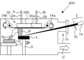
- FIG. 8 is an explanatory diagram showing a schematic configuration of an endohedral fullerene generator according to the sixth embodiment of the present invention.
- the endohedral fullerene generator 600 includes a laser beam irradiation unit 1, an endoscopic material support unit 5, a crucible 6, a heating unit 7, and a vacuum container 9, similar to the endohedral fullerene generator 100.
- the fullerene deposition substrate 30 includes a deposition plate 30a and a cooling plate 30b.
- the cooling plate 30b can be configured in the same manner as the cooling plate 3b described in the first embodiment.
- the deposition plate 30a is formed in a sheet shape, and changes the position at which the fullerene deposit is deposited based on winding and feeding by the winding roller 18a and the feeding roller 18b, which is performed while being in contact with the cooling plate 3b. Can do.
- the deposition plate 30a is not particularly limited as long as it has the necessary heat resistance, and can be composed of known molybdenum or the like.
- the area of the fullerene deposition substrate 30 on which the fullerene deposits are deposited can be enlarged, and the endohedral fullerene is produced in large quantities through a continuous generation process. be able to.
- the endohedral fullerene various substances can be encapsulated, and application to various fields can be expected.
- the magnetic endohedral fullerene can be efficiently generated by encapsulating atoms having magnetism such as iron, nickel, and cobalt. Can be used as a drug delivery material.
- boron-containing fullerene or gadonium-encapsulating fullerene can be generated with high efficiency.
- the boron-encapsulating fullerene or the gadonium-encapsulating fullerene can be used as a neutron capture agent that can be used for capture therapy.
- nitrogen-encapsulated fullerene containing nitrogen atoms can be generated with high efficiency, and the nitrogen-encapsulated fullerene can be applied to a quantum computer. There is expected.
- the nitrogen-encapsulated fullerene, the boron-encapsulated fullerene, and the gadonium-encapsulated fullerene can be used as a contrast agent that can be used for magnetic resonance images.
- Example 1 The endohedral fullerene production
- the deposition plate 3a and the cooling plate 3b are allowed to pass through the laser light introduced from the window portion 1c, and irradiate the inclusion material 4 disposed on the inclusion material support portion 5 with a diameter of 5 mm.
- the holes are in communication.
- the fullerene deposition substrate 3 is supported via the coolant introduction pipe 2a and the coolant discharge pipe 2b and cooled by the chiller.
- the distance between the guide tube 6a of the crucible 6 and the deposition plate 3a was about 20 mm at the shortest distance, and the distance between the inclusion material 4 and the deposition plate 3a was about 30 mm at the shortest distance.
- the endohedral fullerene production test was performed as follows. First, solid boron nitride is disposed as the encapsulating substance 4 on the encapsulating substance support 5, and fullerene (C 60 or a mixture of C 60 and C 70 ) as a sublimation material is disposed in the crucible 6. . Next, the pressure in the vacuum vessel 9 was adjusted to 4.0 ⁇ 10 ⁇ 5 Pa. Next, cooling water (about 16 ° C.) was introduced into the cooling plate 3b. Next, the crucible 6 was heated to 800 ° C.
- the laser beam irradiated from the laser beam irradiation unit 1 is introduced into the vacuum vessel 9 through the window 1c by changing the focal length by the condenser lens 1b, and irradiated to the boron nitride to dissolve the boron nitride. Issued. In the particle group generated by ablation, boron atoms, boron ions, boron clusters, nitrogen atoms, nitrogen molecules, nitrogen ions, boron nitride clusters, electrons, etc. each having kinetic energy are mixed. The fullerene was made to collide with the fullerene sublimate or the fullerene deposit deposited on the deposition plate 3a in a very high density state (about 10 21 m ⁇ 3 ).
- the kinetic energy applied by irradiating the boron nitride with the laser beam by the laser beam irradiation unit 1 will be described.
- the energy of the laser beam oscillated in the laser beam irradiation unit 1 and the nitrogen atoms and nitrogen ions present in the particle group generated by the ablation of the boron nitride The relationship with kinetic energy was measured.
- the kinetic energy was measured by Doppler spectroscopic measurement (focal length 1 m, diffraction grating groove interval 2,400 grooves / mm) of the ablation region.
- FIG. 9 shows the kinetic energy of nitrogen atoms and nitrogen atom ions present in the particle group generated by the ablation of the boron nitride when the energy of the laser beam oscillated from the laser beam irradiation unit 1 is changed. It is a figure which shows the laser energy dependence. Note that the vertical axis in FIG. 9 represents kinetic energy, and the horizontal axis represents the energy of the laser light oscillated from the laser light irradiation unit 1. In FIG. 9, the ⁇ mark plots correspond to nitrogen atom ions, and the ⁇ mark plots correspond to nitrogen atoms.
- the kinetic energy of nitrogen atoms and nitrogen atom ions existing in the particle group generated by ablation changed the energy of the laser beam from 0.3 J to 0.8 J.
- nitrogen atoms were 45 eV to 65 eV and nitrogen ions were 15 eV to 65 eV.
- Reference Document 4 it has been shown by quantum molecular dynamics calculation that the kinetic energy that a nitrogen atom should have in order to generate nitrogen-encapsulated fullerene is 40 eV to 80 eV.
- the kinetic energy for encapsulating nitrogen atoms and nitrogen atom ions in the particle group in the fullerene can be granted.
- the kinetic energy in the case of including a substance other than nitrogen can be obtained from the method based on the equations (1) to (3).
- FIG. 10 shows a result of measuring a sample obtained by dissolving a deposit on the deposition plate 3a with toluene and performing a filtration treatment by an electron spin resonance method.
- the vertical axis indicates the electron spin resonance spectrum intensity
- the horizontal axis indicates the magnetic field intensity.
- M I represents a nuclear spin.
- an electron spin resonance spectrum peculiar to nitrogen-encapsulated fullerene can be confirmed.
- the endohedral fullerene production test in Example 1 is able to produce the nitrogen-encapsulated fullerene, and the energy of the laser beam is adjusted with respect to nitrogen atoms and nitrogen ions in the particles. Since the nitrogen-containing fullerene is generated by imparting kinetic energy suitable for inclusion in fullerene, the nitrogen-containing fullerene can be generated with high efficiency. Therefore, in the endohedral fullerene generating apparatus according to the first embodiment, by controlling the laser beam irradiation energy, the endohedral fullerene can be produced with high efficiency with an energy saving apparatus configuration using a laser.
- Example 2 The endohedral fullerene production
- the endohedral fullerene generation device according to the second embodiment is the same as the endohedral fullerene generation device according to the first embodiment except that the microwave antenna 13 connected to the microwave supply source 12 and the gas supply source 14 are arranged. Configured.
- the microwave antenna 13 is formed with a half-wavelength of the microwave to be introduced, and the side on which the laser beam is irradiated on the side of the inclusion substance 4 opposite to the side where the inclusion substance support 5 is disposed. It is arranged near.
- argon gas is supplied from the gas supply source 14 so that the pressure in the vacuum vessel 9 becomes 30 mTorr, and the microwave (2.45 GHz) is supplied from the microwave antenna 13.
- 150 W is introduced into the vacuum vessel 9, and solid boron is disposed as the inclusion material 4 on the rotating support column 5, and the laser beam is applied from the laser beam irradiation unit 1 to the boron with an irradiation energy of 0.6 J. Irradiation was performed to ablate the boron, and a measurement test of the emission intensity of boron atoms and boron ions in the generated particles was performed.
- the emitted light intensity measured the radiated light from the said particle group through the quartz window installed in the vacuum vessel 9, providing the spectrometer outside the vacuum vessel 9.
- FIG. 11 shows the test results of the measurement tests of the respective emission intensities in Example 2 and Reference Example 1.
- the solid line expressed as “with microwave” indicates the test result of the emission intensity measurement test in Example 2
- the broken line expressed as “without microwave” indicates the emission in Reference Example 1.
- the test results of the strength measurement test are shown.
- FIG. 11 it is confirmed that the emission intensity of boron ions and neutral particles in Example 2 is higher than that in Reference Example 1.
- the emission intensity is detected higher in the ion state than in the neutral particle state. That is, it is considered that collisions with electrons gaining energy by introducing the microwave contribute to the ionization (ionization) of the neutral particles.
Landscapes
- Chemical & Material Sciences (AREA)
- Organic Chemistry (AREA)
- Engineering & Computer Science (AREA)
- Materials Engineering (AREA)
- Nanotechnology (AREA)
- Inorganic Chemistry (AREA)
- Carbon And Carbon Compounds (AREA)
- Physical Vapour Deposition (AREA)
Abstract
【課題】多種多様な物質を内包させることができ、省エネルギーで効率良く前記物質をフラーレン中に内包する内包フラーレンを生成可能な内包フラーレン生成装置及び生成方法を提供すること。 【解決手段】内包フラーレン生成装置100は、内包用物質4が支持される内包用物質支持部5と、坩堝6及び加熱部7を有するフラーレン放散部と、前記フラーレン放散部から放散されるフラーレン昇華体を堆積させるフラーレン堆積基板3と、内包用物質4にレーザ光を照射して溶発させるとともに、内包用物質4中の内包物質に対しフラーレンに内包させる運動エネルギーを付与するように照射エネルギーが制御されるレーザ光照射部1と、真空容器9と、を有し、溶発状態で拡散され、前記運動エネルギーが制御された状態の内包用物質4を前記フラーレン昇華体等と接触させ、内包フラーレンを生成させることを特徴とする。
Description
本発明は、フラーレンの内部空間に多様な物質を内包させた内包フラーレンを製造する内包フラーレン生成装置及び生成方法に関する。
様々な産業分野において、ナノカーボンに関する研究が盛んに行われている。前記ナノカーボンの1つとしてフラーレンがある。前記フラーレンは、多数の炭素原子が球状に結合したもので、化学式がCn(n=60,70,76,78,80,82・・・)で表され、特に炭素原子が60個結合したものをC60フラーレンと言う。このC60フラーレンは、前記フラーレンを生成する際、最も高い割合で生成されるものである。
前記フラーレンの内部には真空の空間があり、この空間に対して金属及び非金属の原子、分子、イオンが内包された内包フラーレンは、従来の前記フラーレンには存在しない特性(半導体特性、超伝導体特性、スピン特性、及び磁性など)を有し、新規機能性材料として期待されている。
前記内包フラーレンの製造手法としては、アーク放電法、レーザ蒸発法、高周波放電法、高温高圧処理法等の物理的手法、及び化学的手法によるものが提案されている。具体的には、以下の様な製造手法が提案されている。
前記フラーレンの内部には真空の空間があり、この空間に対して金属及び非金属の原子、分子、イオンが内包された内包フラーレンは、従来の前記フラーレンには存在しない特性(半導体特性、超伝導体特性、スピン特性、及び磁性など)を有し、新規機能性材料として期待されている。
前記内包フラーレンの製造手法としては、アーク放電法、レーザ蒸発法、高周波放電法、高温高圧処理法等の物理的手法、及び化学的手法によるものが提案されている。具体的には、以下の様な製造手法が提案されている。
例えば、前記物理的手法によるものとして、炭素と金属をカーバイド化させた混合ロッドを原材料としてアーク放電又はレーザ蒸発を行い、生成した金属内包フラーレンを嫌気下で回収することが提案されている(特許文献1参照)。
しかしながら、この提案では、金属内包フラーレンの生成について言及されるものの、生成率が低い問題がある。即ち、前記フラーレンと前記内包させる金属とが混在する状態の前記混合ロッドに対して、前記アーク放電又は前記レーザ蒸発を行い、偶然の確率で前記金属を内包させた前記金属内包フラーレンの生成を期待するものであり、意図的に前記金属内包フラーレンを高効率で生成させることができない。また、生成物中に目的としない不純物(空のフラーレン等)も数多く発生し、かつ、前記不純物と前記金属内包フラーレンとを分離することが困難であるとの問題がある。
しかしながら、この提案では、金属内包フラーレンの生成について言及されるものの、生成率が低い問題がある。即ち、前記フラーレンと前記内包させる金属とが混在する状態の前記混合ロッドに対して、前記アーク放電又は前記レーザ蒸発を行い、偶然の確率で前記金属を内包させた前記金属内包フラーレンの生成を期待するものであり、意図的に前記金属内包フラーレンを高効率で生成させることができない。また、生成物中に目的としない不純物(空のフラーレン等)も数多く発生し、かつ、前記不純物と前記金属内包フラーレンとを分離することが困難であるとの問題がある。
また、前記物理的手法によるものとして、窒素ガスを原料としてプラズマ放電による窒素イオン及び窒素分子イオンを生成するとともに、フラーレンの堆積基板上に負のバイアス電圧を印加することで前記窒素イオン及び前記窒素分子イオンを前記堆積基板に向けて加速させて前記フラーレンと衝突させることにより窒素内包フラーレンを生成する手法が提案されている(特許文献2,3参照)。
しかしながら、この提案においても、生成率が1%以下にとどまり、依然として生成率が低い問題がある。更に、この提案によって前記フラーレン内に内包させる物質としては、窒素イオン及び窒素分子イオンに限られ、多種多様な物質に適応させることが困難であるという問題がある。
しかしながら、この提案においても、生成率が1%以下にとどまり、依然として生成率が低い問題がある。更に、この提案によって前記フラーレン内に内包させる物質としては、窒素イオン及び窒素分子イオンに限られ、多種多様な物質に適応させることが困難であるという問題がある。
また、前記物理的手法によるものとして、ニッケル金属に対し高いバイアス電圧を印加し電子ビームを照射してニッケルプラズマを生成させるとともに、フラーレンを堆積させた基板上に負のバイアス電圧を印加し前記ニッケルプラズマ中のニッケルイオンのみを前記基板に向けて加速させ、これを前記フラーレンと衝突させることでニッケル内包フラーレンを生成する手法が提案されている(特許文献4参照)。
しかしながら、この提案では、前記高エネルギーの電子ビーム生成のために、フィラメント電源500W、ビーム電源1000W(バイアス電圧5k∨、エミッション電流200mA)が必要であり、更に生成量を増加させる場合には、より多くの電流を必要とするため、前記ニッケル内包フラーレンの生成に必要な消費エネルギーが過大となる問題がある。
しかしながら、この提案では、前記高エネルギーの電子ビーム生成のために、フィラメント電源500W、ビーム電源1000W(バイアス電圧5k∨、エミッション電流200mA)が必要であり、更に生成量を増加させる場合には、より多くの電流を必要とするため、前記ニッケル内包フラーレンの生成に必要な消費エネルギーが過大となる問題がある。
前記化学的手法によるものとしては、例えば、高圧加熱合成法・気相合成法・プラズマ合成法を利用して、開口フラーレンにメタロセン(フェロセン等)を導入した後、酸化処理・可視光処理を行うことでメタロセンを内包化させたフラーレンを生成し、これを真空中で加熱することにより前記フラーレン中の前記メタロセンを分解して、分解物としての磁性金属原子が内包化されたフラーレンを生成することが提案されている(特許文献5参照)。
しかしながら、こうした化学的手法では、前記フラーレンに物質を内包させるための処理として、別途、溶媒中で前記フラーレンを開口させた開口フラーレンを合成する処理、及び、前記物質を内部に導入後、溶媒中で前記開口フラーレンの開口を封鎖する処理等が必要であることから、前記内包フラーレンの生成に多くの手間と時間を要する問題がある。また、前記フラーレンに内包させる物質が前記溶媒中で扱うことが可能なものに限定される問題がある。
しかしながら、こうした化学的手法では、前記フラーレンに物質を内包させるための処理として、別途、溶媒中で前記フラーレンを開口させた開口フラーレンを合成する処理、及び、前記物質を内部に導入後、溶媒中で前記開口フラーレンの開口を封鎖する処理等が必要であることから、前記内包フラーレンの生成に多くの手間と時間を要する問題がある。また、前記フラーレンに内包させる物質が前記溶媒中で扱うことが可能なものに限定される問題がある。
本発明は、従来技術における前記諸問題を解決し、多種多様な物質を内包させることができ、省エネルギーで効率良く前記物質をフラーレン中に内包する内包フラーレンを生成可能な内包フラーレン生成装置及び生成方法を提供することを課題とする。
前記課題を解決するための手段としては、以下の通りである。即ち、
<1> 固体の内包用物質が支持される内包用物質支持部と、固体のフラーレンが導入される坩堝及び前記坩堝を加熱してフラーレン昇華体を前記坩堝から放散させる加熱部を有するフラーレン放散部と、前記フラーレン放散部から放散される前記フラーレン昇華体をフラーレン堆積体として堆積させるフラーレン堆積基板と、前記内包用物質にレーザ光を照射して溶発させるとともに、前記内包用物質中の内包物質に対し前記フラーレンに内包させる運動エネルギーの全部又は一部を付与するように前記レーザ光の照射エネルギーが制御されるレーザ光照射部と、前記内包用物質支持部、前記フラーレン放散部及び前記フラーレン堆積基板が内部に配されるとともに、外部に配される前記レーザ光照射部から照射される前記レーザ光を前記内包用物質支持部に向けて導入可能とされる窓部が形成される真空容器と、を有し、溶発状態で拡散され、前記運動エネルギーが制御された状態の前記内包用物質を前記フラーレン昇華体及び前記フラーレン堆積体の少なくともいずれかと接触させ、前記フラーレンに前記内包物質が内包された内包フラーレンを生成させることを特徴とする内包フラーレン生成装置。
<2> フラーレン堆積基板が、フラーレン昇華体の固体相への相変化を促進させる冷却部を有する前記<1>に記載の内包フラーレン生成装置。
<3> フラーレン放散部における坩堝が、フラーレン堆積基板に向けてフラーレン昇華体を放散させる案内管を有する前記<1>から<2>のいずれかの記載の内包フラーレン生成装置。
<4> 案内管が、基端側からフラーレン昇華体を放散させる先端側に向けて拡開されるテーパ構造を有する前記<3>に記載の内包フラーレン生成装置。
<5> フラーレン放散部における坩堝が、内部から外部へフラーレン昇華体を放散させる放散経路中にメッシュ構造を有する前記<1>から<4>のいずれかに記載の内包フラーレン生成装置。
<6> フラーレン堆積基板が電極材料で形成される電極部を有するとともに、前記電極部に電圧を印加する電圧印加部が配される前記<1>から<5>のいずれかに記載の内包フラーレン生成装置。
<7> 溶発状態で拡散される内包用物質にマイクロ波を導入するマイクロ波導入部が真空容器内に配される前記<1>から<6>のいずれかに記載の内包フラーレン生成装置。
<8> 真空容器に、溶発状態で拡散される内包用物質に向けてガスを導入するガス導入部が形成される前記<1>から<7>のいずれかに記載の内包フラーレン生成装置。
<9> 溶発状態で拡散される内包用物質に対し補助レーザ光を照射して前記内包用物質中のバルク粒子を細粒子化させる補助レーザ照射部が真空容器の外部に配されるとともに、前記真空容器に前記補助レーザ光照射部から照射される前記補助レーザ光を溶発状態で拡散される前記内包用物質に向けて導入可能とされる窓部が形成される前記<1>から<8>のいずれかに記載の内包フラーレン生成装置。
<10> 溶発状態で拡散される内包用物質中の荷電粒子の拡散軌道を制御可能とさせる磁場発生部が真空容器内に配される前記<1>から<9>のいずれかに記載の内包フラーレン生成装置。
<11> 固体のフラーレンを加熱してフラーレン昇華体を発生させるフラーレン昇華工程と、固体の内包用物質にレーザ光を照射して溶発させるとともに、前記内包用物質中の内包物質に対し前記フラーレンに内包させる運動エネルギーの全部又は一部を付与するように前記レーザ光の照射エネルギーが制御されるレーザ光照射工程と、前記フラーレン昇華体をフラーレン堆積体としてフラーレン堆積基板上に堆積させるフラーレン堆積工程と、溶発状態で拡散され、前記運動エネルギーが制御された状態の前記内包用物質を前記フラーレン昇華体及び前記フラーレン堆積体の少なくともいずれかと接触させ、前記フラーレンに前記内包物質が内包された内包フラーレンを生成させる内包フラーレン生成工程と、を含むことを特徴とする内包フラーレン生成方法。
<12> フラーレン堆積基板に電圧を印加する電圧印加工程を含む前記<11>に記載の内包フラーレン生成方法。
<13> 溶発状態で拡散される内包用物質にマイクロ波を導入するマイクロ波導入工程を含む前記<11>から<12>のいずれかに記載の内包フラーレン生成方法。
<1> 固体の内包用物質が支持される内包用物質支持部と、固体のフラーレンが導入される坩堝及び前記坩堝を加熱してフラーレン昇華体を前記坩堝から放散させる加熱部を有するフラーレン放散部と、前記フラーレン放散部から放散される前記フラーレン昇華体をフラーレン堆積体として堆積させるフラーレン堆積基板と、前記内包用物質にレーザ光を照射して溶発させるとともに、前記内包用物質中の内包物質に対し前記フラーレンに内包させる運動エネルギーの全部又は一部を付与するように前記レーザ光の照射エネルギーが制御されるレーザ光照射部と、前記内包用物質支持部、前記フラーレン放散部及び前記フラーレン堆積基板が内部に配されるとともに、外部に配される前記レーザ光照射部から照射される前記レーザ光を前記内包用物質支持部に向けて導入可能とされる窓部が形成される真空容器と、を有し、溶発状態で拡散され、前記運動エネルギーが制御された状態の前記内包用物質を前記フラーレン昇華体及び前記フラーレン堆積体の少なくともいずれかと接触させ、前記フラーレンに前記内包物質が内包された内包フラーレンを生成させることを特徴とする内包フラーレン生成装置。
<2> フラーレン堆積基板が、フラーレン昇華体の固体相への相変化を促進させる冷却部を有する前記<1>に記載の内包フラーレン生成装置。
<3> フラーレン放散部における坩堝が、フラーレン堆積基板に向けてフラーレン昇華体を放散させる案内管を有する前記<1>から<2>のいずれかの記載の内包フラーレン生成装置。
<4> 案内管が、基端側からフラーレン昇華体を放散させる先端側に向けて拡開されるテーパ構造を有する前記<3>に記載の内包フラーレン生成装置。
<5> フラーレン放散部における坩堝が、内部から外部へフラーレン昇華体を放散させる放散経路中にメッシュ構造を有する前記<1>から<4>のいずれかに記載の内包フラーレン生成装置。
<6> フラーレン堆積基板が電極材料で形成される電極部を有するとともに、前記電極部に電圧を印加する電圧印加部が配される前記<1>から<5>のいずれかに記載の内包フラーレン生成装置。
<7> 溶発状態で拡散される内包用物質にマイクロ波を導入するマイクロ波導入部が真空容器内に配される前記<1>から<6>のいずれかに記載の内包フラーレン生成装置。
<8> 真空容器に、溶発状態で拡散される内包用物質に向けてガスを導入するガス導入部が形成される前記<1>から<7>のいずれかに記載の内包フラーレン生成装置。
<9> 溶発状態で拡散される内包用物質に対し補助レーザ光を照射して前記内包用物質中のバルク粒子を細粒子化させる補助レーザ照射部が真空容器の外部に配されるとともに、前記真空容器に前記補助レーザ光照射部から照射される前記補助レーザ光を溶発状態で拡散される前記内包用物質に向けて導入可能とされる窓部が形成される前記<1>から<8>のいずれかに記載の内包フラーレン生成装置。
<10> 溶発状態で拡散される内包用物質中の荷電粒子の拡散軌道を制御可能とさせる磁場発生部が真空容器内に配される前記<1>から<9>のいずれかに記載の内包フラーレン生成装置。
<11> 固体のフラーレンを加熱してフラーレン昇華体を発生させるフラーレン昇華工程と、固体の内包用物質にレーザ光を照射して溶発させるとともに、前記内包用物質中の内包物質に対し前記フラーレンに内包させる運動エネルギーの全部又は一部を付与するように前記レーザ光の照射エネルギーが制御されるレーザ光照射工程と、前記フラーレン昇華体をフラーレン堆積体としてフラーレン堆積基板上に堆積させるフラーレン堆積工程と、溶発状態で拡散され、前記運動エネルギーが制御された状態の前記内包用物質を前記フラーレン昇華体及び前記フラーレン堆積体の少なくともいずれかと接触させ、前記フラーレンに前記内包物質が内包された内包フラーレンを生成させる内包フラーレン生成工程と、を含むことを特徴とする内包フラーレン生成方法。
<12> フラーレン堆積基板に電圧を印加する電圧印加工程を含む前記<11>に記載の内包フラーレン生成方法。
<13> 溶発状態で拡散される内包用物質にマイクロ波を導入するマイクロ波導入工程を含む前記<11>から<12>のいずれかに記載の内包フラーレン生成方法。
本発明によれば、従来技術における前記諸問題を解決することができ、多種多様な物質を内包させることができ、省エネルギーで効率良く前記物質をフラーレン中に内包する内包フラーレンを生成可能な内包フラーレン生成装置及び生成方法を提供することができる。
(内包フラーレン生成装置及び内包フラーレン生成方法)
<第1実施形態>
本発明の第1実施形態に係る内包フラーレン生成装置を図面を参照しつつ説明する。図1は、本発明の第1実施形態に係る内包フラーレン生成装置の概略構成を示す説明図である。
該図1に示すように、内包フラーレン生成装置100は、主としてレーザ光照射部1、フラーレン堆積基板3、内包用物質支持部5、坩堝6、加熱部7及び真空容器9を有して構成される。
<第1実施形態>
本発明の第1実施形態に係る内包フラーレン生成装置を図面を参照しつつ説明する。図1は、本発明の第1実施形態に係る内包フラーレン生成装置の概略構成を示す説明図である。
該図1に示すように、内包フラーレン生成装置100は、主としてレーザ光照射部1、フラーレン堆積基板3、内包用物質支持部5、坩堝6、加熱部7及び真空容器9を有して構成される。
レーザ光照射部1は、内包用物質4にレーザ光を照射して溶発させるとともに、内包用物質4中の内包物質に対しフラーレンに内包させる運動エネルギーの全部又は一部を付与するように前記レーザ光の照射エネルギーが制御される部であり、本例では、内包用物質4に対し前記運動エネルギーの全部を付与するように前記レーザ光の照射エネルギーが制御される。
従来における前記物理的手法では、炭素と金属との混合ロッドを内包フラーレンの生成原料とし、これにレーザ光を照射して蒸発させることで、偶然の確率で前記金属を内包させた前記金属内包フラーレンが生成されることとしている。
これに対し、本発明に係る内包フラーレン生成装置では、前記内包物質に対し前記運動エネルギーを付与するように前記レーザ光の照射エネルギーが制御されることで、前記内包物質に対して前記フラーレンに内包させるのに適した前記運動エネルギーを付与し、前記フラーレンに対して意図的に前記内包物質を内包させることとする。
なお、本明細書において、「効率良く内包フラーレンを生成する」とは、前記レーザ光の照射エネルギーを制御することで、前記内包物質に対して前記フラーレンに内包させるのに適した前記運動エネルギーを付与した状態で、前記フラーレンに対し内包用物質4を内包させることを意味する。
従来における前記物理的手法では、炭素と金属との混合ロッドを内包フラーレンの生成原料とし、これにレーザ光を照射して蒸発させることで、偶然の確率で前記金属を内包させた前記金属内包フラーレンが生成されることとしている。
これに対し、本発明に係る内包フラーレン生成装置では、前記内包物質に対し前記運動エネルギーを付与するように前記レーザ光の照射エネルギーが制御されることで、前記内包物質に対して前記フラーレンに内包させるのに適した前記運動エネルギーを付与し、前記フラーレンに対して意図的に前記内包物質を内包させることとする。
なお、本明細書において、「効率良く内包フラーレンを生成する」とは、前記レーザ光の照射エネルギーを制御することで、前記内包物質に対して前記フラーレンに内包させるのに適した前記運動エネルギーを付与した状態で、前記フラーレンに対し内包用物質4を内包させることを意味する。
前記フラーレンに内包させるのに適した前記運動エネルギーとしては、量子分子動力学計算により求めることが可能である。具体的には、Born-Oppenheimer断熱近似を利用し、前記フラーレン中の炭素原子核と初期エネルギーが与えられた前記内包物質原子核のまわりを動くグランドカノニカル分布を持つ電子についての波動関数を解くことで、系の平衡状態を求める。このとき、前記電子のハミルトニアンHは、下記式(1)で表される。

ここで、前記電子がフェルミ粒子であることを考慮すると、前記電荷密度ρ及び化学ポテンシャルμは、それぞれ下記式(2),(3)で与えられる。

前記フラーレン及び前記内包物質に含まれる、それぞれの電子について前記式(1)~(3)を解き、それぞれの電子について温度一定の下で波動関数の平衡解を求めた後、前記炭素原子核及び前記内包物質原子核の各原子核について、ヘルマンファインマン力を考慮し、前記原子核の位置を修正することで系全体の平衡状態を時間ステップ毎に繰り返して求め、最終的な系の平衡状態を決定する。
この手法により、前記内包物質を前記フラーレンに内包するために必要な運動エネルギーを求めるために、前記内包物質の初期エネルギー(内包させるための運動エネルギー)を変化させ、その変化させた値のそれぞれの場合について、前記式(1)~(3)を数値的に解くことで、各初期エネルギーでの最終的な系の状態が決定される。この手法により、前記内包物質の初期エネルギーを変化させ、最終的な平衡状態において、前記内包物質が前記フラーレン中に内包されるエネルギー、及び内包されないエネルギーの境界を調べることにより、前記内包物質を前記フラーレンに内包するために必要な前記運動エネルギーが求められる。
なお、前記手法については、下記参考文献1を参照することができる。
参考文献1:K. Ohno, Y. Maruyama, and Y. Kawazoe, Physical Review B, vol. 53, No. 7, pp. 4078-4082 (1996)
なお、前記手法については、下記参考文献1を参照することができる。
参考文献1:K. Ohno, Y. Maruyama, and Y. Kawazoe, Physical Review B, vol. 53, No. 7, pp. 4078-4082 (1996)
例えば、下記参考文献2では、前記内包物質としてのBeの2価イオンに対し5eVの前記運動エネルギーを与えて前記フラーレン(C60)に衝突させ、7Be@C60が生成されることを前記手法により明らかにしている。
また、下記参考文献3では、前記内包物質としての1価のLiイオンに対し5eVの前記運動エネルギーを与えて前記フラーレン(C60)に衝突させ、Li@C60が生成されることが示されている。
参考文献2:T. Ohtsuki, K. Matsumoto, K. Ohno, Y. Maruyama, Y. Kawazoe, K. Sueki, and k. Kikuchi, Physical Review Letters, vol. 77, No. 17, pp. 3522-3524 (1996)
参考文献3:K. Ohno, Y. Maruyama, K. Esfarjani, Y. Kawazoe, N. Sato, R. Hatakeyama, T. Hirata, and M. Niwano,, Physical Review Letters, vol. 76, No. 19, pp. 3590-3593 (1996)
また、下記参考文献3では、前記内包物質としての1価のLiイオンに対し5eVの前記運動エネルギーを与えて前記フラーレン(C60)に衝突させ、Li@C60が生成されることが示されている。
参考文献2:T. Ohtsuki, K. Matsumoto, K. Ohno, Y. Maruyama, Y. Kawazoe, K. Sueki, and k. Kikuchi, Physical Review Letters, vol. 77, No. 17, pp. 3522-3524 (1996)
参考文献3:K. Ohno, Y. Maruyama, K. Esfarjani, Y. Kawazoe, N. Sato, R. Hatakeyama, T. Hirata, and M. Niwano,, Physical Review Letters, vol. 76, No. 19, pp. 3590-3593 (1996)
レーザ光照射部1としては、例えば、図示のようにレーザ光源1aと集光するレンズ1bとで構成される。
前記レーザ光を用いることで、前記内包物質に対して内包に適した前記運動エネルギーを付与するための照射エネルギーの制御が容易とされるとともに、従来の電子ビームを用いる場合に比べて、大幅に省エネルギー化させることができる。
即ち、レーザ光源1aの出力及びレンズ1bによる焦点距離の調整等を行うだけで、容易かつ省エネルギーに内包用物質4に対する前記運動エネルギーの付与を行うことができる。
なお、レーザ光源1a及びレンズ1bとしては、特に制限はなく、レーザ溶発装置等に用いられる公知のレーザ機器から適宜選択して用いることができる。また、レーザ光照射部1として、内包用物質4を溶発させること、前記内包物質に前記運動エネルギーを付与することができる限り、レーザ光源1a及びレンズ1bによる構成に代えて、他の公知のレーザ機器による構成を採用してもよい。
前記レーザ光を用いることで、前記内包物質に対して内包に適した前記運動エネルギーを付与するための照射エネルギーの制御が容易とされるとともに、従来の電子ビームを用いる場合に比べて、大幅に省エネルギー化させることができる。
即ち、レーザ光源1aの出力及びレンズ1bによる焦点距離の調整等を行うだけで、容易かつ省エネルギーに内包用物質4に対する前記運動エネルギーの付与を行うことができる。
なお、レーザ光源1a及びレンズ1bとしては、特に制限はなく、レーザ溶発装置等に用いられる公知のレーザ機器から適宜選択して用いることができる。また、レーザ光照射部1として、内包用物質4を溶発させること、前記内包物質に前記運動エネルギーを付与することができる限り、レーザ光源1a及びレンズ1bによる構成に代えて、他の公知のレーザ機器による構成を採用してもよい。
好適に用いることのできるレーザ光源1aとしては、パルスレーザが挙げられる。前記パルスレーザとしては、特に制限はないが、レーザエネルギー(レーザ出力)が1,000mJ/パルス以下であり、作動繰返し周波数が1Hz~1,000Hzであり、パルス幅が6ns~150nsであるものが好ましい。これら条件を満たす前記パルスレーザを用いると、レーザエネルギー密度の最適化により、前記内包物質の内包化に適した前記運動エネルギー帯を生成し易く、また、集光レンズとしてのレンズ1bの位置を調整してレーザ光照射面積を最適化することで、4.5%以上の高生成率で前記内包フラーレンを生成することができる。
なお、本明細書において、前記内包フラーレンの生成率は、次のように定義される。
即ち、前記内包フラーレン生成装置を用いて前記内包フラーレンを生成後、前記内包フラーレン生成装置から回収される堆積物に対し、飛行時間型質量分析装置(TOF-MASS)を用いた測定を行い、前記堆積物中に含まれる前記内包用物質が内包されていない空のフラーレンのピーク強度の合算値と前記内包用物質が内包された前記内包フラーレンのピーク強度の合算値とを算出する。これらの算出結果に基づき、前記生成率は、下記式(4)で与えられる。
即ち、前記内包フラーレン生成装置を用いて前記内包フラーレンを生成後、前記内包フラーレン生成装置から回収される堆積物に対し、飛行時間型質量分析装置(TOF-MASS)を用いた測定を行い、前記堆積物中に含まれる前記内包用物質が内包されていない空のフラーレンのピーク強度の合算値と前記内包用物質が内包された前記内包フラーレンのピーク強度の合算値とを算出する。これらの算出結果に基づき、前記生成率は、下記式(4)で与えられる。

ただし、窒素内包フラーレンなど、不対電子を有する物質を前記フラーレンへ内包させた場合には、電子スピン共鳴法及びUV/vis吸収スペクトル法により、前記生成率が次のように定義される。
即ち、前記内包フラーレン生成装置を用いて前記内包フラーレンを生成後、前記内包フラーレン生成装置から回収される前記堆積物には、前記内包フラーレン以外に前記空のフラーレンやヘテロフラーレンなどの不純物が含まれる。前記堆積物をトルエン等の溶媒に入れて、溶媒に溶けるものと、溶けないものに分離する。ここで、1種単独又は2種以上の溶媒を用いることによって、前記不純物と、前記空のフラーレン及び前記内包フラーレンとを分離する。分離後の溶媒には前記空のフラーレンと前記内包フラーレンとが溶解されている。
前記溶媒に溶解される試料に対し、前記電子スピン共鳴法による分析を行い、前記内包用物質の不対電子に対応した信号から強度を得る。このとき、予め、前記内包用物質の不対電子を有した状態を作成できる試薬を用いて前記電子スピン共鳴法によって得られる信号強度とモル濃度との関係性を表すグラフを作成しておけば、前記信号強度を前記グラフと照らし合わせることで前記内包フラーレンのモル濃度(mol/L)が算出される。
また、前記溶媒に溶解される試料に対し、前記UV/vis吸収スペクトル法を行い、前記フラーレンによって吸収される可視吸収スペクトル221nm、271nm、347nmの吸収強度から前記空のフラーレンの含有モル濃度が算出される。
これらの算出結果に基づき、不対電子を有する物質を前記フラーレンへ内包させた場合の前記生成率は、下記式(5)により与えられる。
即ち、前記内包フラーレン生成装置を用いて前記内包フラーレンを生成後、前記内包フラーレン生成装置から回収される前記堆積物には、前記内包フラーレン以外に前記空のフラーレンやヘテロフラーレンなどの不純物が含まれる。前記堆積物をトルエン等の溶媒に入れて、溶媒に溶けるものと、溶けないものに分離する。ここで、1種単独又は2種以上の溶媒を用いることによって、前記不純物と、前記空のフラーレン及び前記内包フラーレンとを分離する。分離後の溶媒には前記空のフラーレンと前記内包フラーレンとが溶解されている。
前記溶媒に溶解される試料に対し、前記電子スピン共鳴法による分析を行い、前記内包用物質の不対電子に対応した信号から強度を得る。このとき、予め、前記内包用物質の不対電子を有した状態を作成できる試薬を用いて前記電子スピン共鳴法によって得られる信号強度とモル濃度との関係性を表すグラフを作成しておけば、前記信号強度を前記グラフと照らし合わせることで前記内包フラーレンのモル濃度(mol/L)が算出される。
また、前記溶媒に溶解される試料に対し、前記UV/vis吸収スペクトル法を行い、前記フラーレンによって吸収される可視吸収スペクトル221nm、271nm、347nmの吸収強度から前記空のフラーレンの含有モル濃度が算出される。
これらの算出結果に基づき、不対電子を有する物質を前記フラーレンへ内包させた場合の前記生成率は、下記式(5)により与えられる。

なお、前記フラーレンの可視吸収スペクトルについては、下記参考文献4を参照することができる。
参考文献4:S. Kazaoui, R. Ross and N. Minami, Solid State Commun., 90, 623 (1994)
フラーレン堆積基板3は、坩堝6(フラーレン放散部)から放散されるフラーレン昇華体をフラーレン堆積体として堆積させるものであり、本例では、堆積板3aと冷却板3bとを貼り合せた構成とされる。
堆積板3a及び冷却板3bの形成材料としては、必要な耐熱性を有する限り、特に制限はなく、公知の基板材料を用いることができる。
なお、本例では、フラーレン堆積基板3(堆積板3aと冷却板3b)にレーザ光照射部1から内包用物質4に向けて照射される前記レーザ光を通過させるための通過孔が形成される。
堆積板3a及び冷却板3bの形成材料としては、必要な耐熱性を有する限り、特に制限はなく、公知の基板材料を用いることができる。
なお、本例では、フラーレン堆積基板3(堆積板3aと冷却板3b)にレーザ光照射部1から内包用物質4に向けて照射される前記レーザ光を通過させるための通過孔が形成される。
冷却板3bは、前記フラーレン昇華体の固体相への相変化を促進させる冷却部としての役割を有する。即ち、冷却板3bとしては、例えば、冷却材導入管2a及び冷却材排出管2bから矢印A及びBの経路で導入及び排出される冷却材の循環経路を内部に有し、冷却制御が可能とされる。このような冷却制御により、真空容器9内に放散される前記フラーレン昇華体を堆積板3a上に吸着等させて効果的に堆積させることができる。
前記冷却材としては、水等の任意の液体やガスを用いることができる。
なお、冷却材導入管2a及び冷却材排出管2bとしては、一端側がチラー等の前記冷却材の温度を制御する公知の冷却装置(不図示)と接続され、他端側の冷却板3bとの接続を介して、フラーレン堆積基板3を真空容器9内で安定的に支持させることにも役立つ。
前記冷却材としては、水等の任意の液体やガスを用いることができる。
なお、冷却材導入管2a及び冷却材排出管2bとしては、一端側がチラー等の前記冷却材の温度を制御する公知の冷却装置(不図示)と接続され、他端側の冷却板3bとの接続を介して、フラーレン堆積基板3を真空容器9内で安定的に支持させることにも役立つ。
内包用物質支持部5は、固体の内包用物質4が支持されるように構成され、例えば、公知の蒸着装置におけるターゲット材支持部等と同様に構成することができる。
例えば、本例では、回転駆動可能な支持柱として構成される。このような構成とすることで、円盤状の内包用物質4を配したときに、回転する内包用物質4に対し前記レーザ光をトラック走査させて照射することができ、内包用物質4に対して効率的に前記レーザ光を照射することができる。
なお、内包用物質4としては、前記フラーレンに内包させる前記内包物質自体であってもよく、前記フラーレンに内包させる前記内包物質を一部に含む物質(例えば、前記内包物質としての原子を含む化合物等)であってもよい。後者の場合、前記内包物質に特有の前記運動エネルギーを付与することで、内包を目的としない他の物質と選別して前記内包物質を選択的に前記フラーレンに内包させることができる。
例えば、本例では、回転駆動可能な支持柱として構成される。このような構成とすることで、円盤状の内包用物質4を配したときに、回転する内包用物質4に対し前記レーザ光をトラック走査させて照射することができ、内包用物質4に対して効率的に前記レーザ光を照射することができる。
なお、内包用物質4としては、前記フラーレンに内包させる前記内包物質自体であってもよく、前記フラーレンに内包させる前記内包物質を一部に含む物質(例えば、前記内包物質としての原子を含む化合物等)であってもよい。後者の場合、前記内包物質に特有の前記運動エネルギーを付与することで、内包を目的としない他の物質と選別して前記内包物質を選択的に前記フラーレンに内包させることができる。
内包用物質4に前記レーザ光が照射されると、内包用物質4の溶発体としてのプルームPが発生する。このプルームPには、前記フラーレン内に内包させる前記内包物質が高密度に含まれる。本例では、プルームPの拡散方向にフラーレン堆積基板3を配し、フラーレン堆積基板3上の前記フラーレン堆積体(気体状で吸着されるフラーレン、冷却により固体状とされるフラーレンを含む)及び前記フラーレン堆積基板3近傍に存する前記フラーレン昇華体とプルームPとを衝突させ、前記運動エネルギーが付与された前記物質を前記フラーレン中に内包させる。
このような観点から、フラーレン堆積基板3と内包用物質4との間の距離は、短いことが好ましく、例えば、最短距離で20mm~70mmとされることが好ましい。
このような観点から、フラーレン堆積基板3と内包用物質4との間の距離は、短いことが好ましく、例えば、最短距離で20mm~70mmとされることが好ましい。
本例では、前記フラーレン放散部が、固体の前記フラーレンが導入される坩堝6、及び坩堝6を加熱して前記フラーレン昇華体を坩堝6から放散させる加熱部7を有して構成される。
坩堝6に導入される前記フラーレンとしては、例えば、市販のフラーレン粉末を用いることができる。
加熱部7としては、特に制限はなく、公知のヒータ装置を用いて構成することができる。
加熱部7における坩堝6の加熱温度としては、特に制限はないが、750℃~1,000℃が好ましい。
坩堝6に導入される前記フラーレンとしては、例えば、市販のフラーレン粉末を用いることができる。
加熱部7としては、特に制限はなく、公知のヒータ装置を用いて構成することができる。
加熱部7における坩堝6の加熱温度としては、特に制限はないが、750℃~1,000℃が好ましい。
坩堝6としては、特に制限はなく、公知の加熱装置に用いられる坩堝と同様のものを用いることができるが、図示のように、管の軸方向の延長上にフラーレン堆積基板3が配され、フラーレン堆積基板3に向けて前記フラーレン昇華体を放散させる案内管6aを有することが好ましい。このような案内管6aを有することで、前記フラーレン昇華体がフラーレン堆積基板3の外方に散逸することを抑制することができる。
また、同じく前記フラーレン昇華体がフラーレン堆積基板3の外方に散逸することを抑制する目的で、フラーレン堆積基板3と坩堝6(案内管6aの放散口)との間の距離は、短いことが好ましく、例えば、最短距離で20mm~100mmとされることが好ましい。
また、同じく前記フラーレン昇華体がフラーレン堆積基板3の外方に散逸することを抑制する目的で、フラーレン堆積基板3と坩堝6(案内管6aの放散口)との間の距離は、短いことが好ましく、例えば、最短距離で20mm~100mmとされることが好ましい。
また、坩堝6としては、特に制限はないが、図2に示す特徴の全部又は一部を有することが好ましい。なお、図2は、坩堝の好適な構成例を説明するための断面図である。
即ち、坩堝6から放散される前記フラーレン昇華体は、固体からの急激な相変化時に突沸等の不安定な挙動を示すことがあり、このような挙動は、フラーレン堆積基板3に向かう前記フラーレン昇華体の量が過剰となることに加えて、前記フラーレンの未昇華粉末がそのまま坩堝6外方に飛散し、昇華量の制御性を低減させる原因となる。
したがって、図2に示すように、坩堝6としては、案内管6a、前記フラーレン(固体原料)を収容する収容部6bに加え、開口径の調整により収容部6内の圧力を調整して前記フラーレン昇華体の突沸等を抑制する開口付き蓋部6c、更には、内部から外部へ前記フラーレン昇華体を放散させる拡散経路中にメッシュ構造6dが形成されることが好ましい。なお、メッシュ構造6dを形成するメッシュ材としては、必要な耐熱性を有するものであれば特に制限はなく、公知のものから適宜選択して用いることができる。
また、案内管6aとしては、収容部6b側である基端側から前記フラーレン昇華体を放散させる先端側に向けて拡開されるテーパ構造を有することが好ましい。
これら特徴の全部又は一部を有すると、前記フラーレン昇華体の前記突沸等に基づく不安定な挙動が抑制され、安定的に前記フラーレン昇華体をフラーレン堆積基板3に供給することができる。
即ち、坩堝6から放散される前記フラーレン昇華体は、固体からの急激な相変化時に突沸等の不安定な挙動を示すことがあり、このような挙動は、フラーレン堆積基板3に向かう前記フラーレン昇華体の量が過剰となることに加えて、前記フラーレンの未昇華粉末がそのまま坩堝6外方に飛散し、昇華量の制御性を低減させる原因となる。
したがって、図2に示すように、坩堝6としては、案内管6a、前記フラーレン(固体原料)を収容する収容部6bに加え、開口径の調整により収容部6内の圧力を調整して前記フラーレン昇華体の突沸等を抑制する開口付き蓋部6c、更には、内部から外部へ前記フラーレン昇華体を放散させる拡散経路中にメッシュ構造6dが形成されることが好ましい。なお、メッシュ構造6dを形成するメッシュ材としては、必要な耐熱性を有するものであれば特に制限はなく、公知のものから適宜選択して用いることができる。
また、案内管6aとしては、収容部6b側である基端側から前記フラーレン昇華体を放散させる先端側に向けて拡開されるテーパ構造を有することが好ましい。
これら特徴の全部又は一部を有すると、前記フラーレン昇華体の前記突沸等に基づく不安定な挙動が抑制され、安定的に前記フラーレン昇華体をフラーレン堆積基板3に供給することができる。
真空容器9は、堆積基板3、内包用物質支持部5、坩堝6及び加熱部7を内部に配するように構成され、また、外部に配されるレーザ光照射部1から照射される前記レーザ光を内包用物質4に向けて導入可能とされる窓部1cと、排気(矢印C方向)により内部の圧力を調整するための排気部8とが形成される(図1参照)。
真空容器9としては、公知の真空容器を利用して構成することができる。
なお、前記内包フラーレン生成処理時における容器内の圧力(背景真空度)としては、特に制限はなく、例えば、1.0×10⁻⁵Pa~1Paとされる。
真空容器9としては、公知の真空容器を利用して構成することができる。
なお、前記内包フラーレン生成処理時における容器内の圧力(背景真空度)としては、特に制限はなく、例えば、1.0×10⁻⁵Pa~1Paとされる。
以上により構成される内包フラーレン生成装置100では、次の操作により前記内包フラーレンを生成することができる。
先ず、坩堝6内に前記フラーレンが導入された状態で加熱部7による加熱を行い、前記フラーレン昇華体を発生させる(フラーレン昇華工程)。
また、内包用物質4に前記レーザ光を照射して溶発させる。この際、前記レーザ光の照射は、前記内包物質に対し、前記フラーレンに内包させる前記運動エネルギーの全部又は一部(本例では、全部)を付与するように前記レーザ光の照射エネルギーを制御して行う(レーザ光照射工程)。
また、前記フラーレン昇華体を前記フラーレン堆積体としてフラーレン堆積基板3上に堆積させる(フラーレン堆積工程)。なお、この操作は、発生する前記フラーレン昇華体の放散先にフラーレン堆積基板3を配して行う。
また、溶発状態で拡散され、前記運動エネルギーが制御された状態の内包用物質4を前記フラーレン昇華体及び前記フラーレン堆積体の少なくともいずれかと接触させ、前記内包物質が前記フラーレンに内包された内包フラーレンを生成させる(内包フラーレン生成工程)。なお、この操作は、溶発状態の内包用物質4のプルームPの拡散先にフラーレン堆積基板3を配して行う。
なお、内包用物質4中の前記フラーレンに内包される前記内包物質が、昇華体、堆積体(気体状で吸着されるフラーレン、固体状とされるフラーレンを含む)のいずれの段階の前記フラーレンに内包されるかは定かではないが、前記内包フラーレンは、最終的にフラーレン堆積基板3に堆積される固体状のものとして回収される。
先ず、坩堝6内に前記フラーレンが導入された状態で加熱部7による加熱を行い、前記フラーレン昇華体を発生させる(フラーレン昇華工程)。
また、内包用物質4に前記レーザ光を照射して溶発させる。この際、前記レーザ光の照射は、前記内包物質に対し、前記フラーレンに内包させる前記運動エネルギーの全部又は一部(本例では、全部)を付与するように前記レーザ光の照射エネルギーを制御して行う(レーザ光照射工程)。
また、前記フラーレン昇華体を前記フラーレン堆積体としてフラーレン堆積基板3上に堆積させる(フラーレン堆積工程)。なお、この操作は、発生する前記フラーレン昇華体の放散先にフラーレン堆積基板3を配して行う。
また、溶発状態で拡散され、前記運動エネルギーが制御された状態の内包用物質4を前記フラーレン昇華体及び前記フラーレン堆積体の少なくともいずれかと接触させ、前記内包物質が前記フラーレンに内包された内包フラーレンを生成させる(内包フラーレン生成工程)。なお、この操作は、溶発状態の内包用物質4のプルームPの拡散先にフラーレン堆積基板3を配して行う。
なお、内包用物質4中の前記フラーレンに内包される前記内包物質が、昇華体、堆積体(気体状で吸着されるフラーレン、固体状とされるフラーレンを含む)のいずれの段階の前記フラーレンに内包されるかは定かではないが、前記内包フラーレンは、最終的にフラーレン堆積基板3に堆積される固体状のものとして回収される。
したがって、内包フラーレン生成装置100及び内包フラーレン生成装置100を用いた内包フラーレン生成方法によれば、前記レーザ光により溶発可能なものを対象として多種多様な物質を前記フラーレンに内包させることができ、また、前記レーザ光を用いることで前記内包フラーレンの生成に必要なエネルギーを省エネルギー化することができ、更に、前記レーザ光の照射エネルギーの制御により内包させる物質が前記内包フラーレンに内包されるのに適した運動エネルギーを付与されるため、高効率に内包フラーレンが生成可能とされる。
内包フラーレン生成装置100としては、図3に示す内包フラーレン生成装置100’のように、レーザ光源1aに代えて、複数のレーザ光源1a’で構成されたレーザ光源を用いて構成してもよい。なお、図3は、第1実施形態に係るフラーレン生成装置の変形例の構成を説明するための説明図である。
<第2実施形態>
次に、本発明の第2実施形態に係る内包フラーレン生成装置を図面を参照しつつ説明する。図4は、本発明の第2実施形態に係る内包フラーレン生成装置の概略構成を示す説明図である。
該図4に示すように、内包フラーレン生成装置200は、内包フラーレン生成装置100と同様にレーザ光照射部1、フラーレン堆積基板3、内包用物質支持部5、坩堝6、加熱部7及び真空容器9を有して構成され、バイアス電源10及びバイアス印加電極11を有すること等が内包フラーレン生成装置100と異なる。
ここでは、内包フラーレン生成装置100と共通する事項の説明を省略し、異なる事項について説明する。
次に、本発明の第2実施形態に係る内包フラーレン生成装置を図面を参照しつつ説明する。図4は、本発明の第2実施形態に係る内包フラーレン生成装置の概略構成を示す説明図である。
該図4に示すように、内包フラーレン生成装置200は、内包フラーレン生成装置100と同様にレーザ光照射部1、フラーレン堆積基板3、内包用物質支持部5、坩堝6、加熱部7及び真空容器9を有して構成され、バイアス電源10及びバイアス印加電極11を有すること等が内包フラーレン生成装置100と異なる。
ここでは、内包フラーレン生成装置100と共通する事項の説明を省略し、異なる事項について説明する。
内包フラーレン生成装置200では、フラーレン堆積基板3における堆積板3aが電極材料で形成され、堆積板3aは、前記フラーレン堆積体を堆積させる役割に加え、電極部としての役割を有する。
堆積板3aと対向して対をなす電極部として、内包用物質4を間に介在させるように、バイアス印加電極11が真空容器9内に配される。
堆積板3a及びバイアス印加電極11は、電圧印加部としてのバイアス電源10に接続され、バイアス電源10から印加される電圧により、堆積板3aとバイアス印加電極11との間に電位差が形成される。
なお、フラーレン堆積基板3(堆積板3a)及びバイアス印加電極11のそれぞれは、真空容器9と絶縁された状態で配される。
堆積板3aと対向して対をなす電極部として、内包用物質4を間に介在させるように、バイアス印加電極11が真空容器9内に配される。
堆積板3a及びバイアス印加電極11は、電圧印加部としてのバイアス電源10に接続され、バイアス電源10から印加される電圧により、堆積板3aとバイアス印加電極11との間に電位差が形成される。
なお、フラーレン堆積基板3(堆積板3a)及びバイアス印加電極11のそれぞれは、真空容器9と絶縁された状態で配される。
溶発状態で拡散される内包用物質4、即ち、プルームPには、原子等の中性粒子及びイオン等の荷電粒子等の粒子が含まれる。
したがって、フラーレン堆積基板3(堆積板3a)に電圧を印加することで、前記中性粒子及び前記荷電粒子のいずれかを選択的に前記フラーレンに内包させ易い(電圧印加工程)。
即ち、フラーレン堆積基板3(堆積板3a)に正又は負のバイアス電圧を印加することで、正負いずれかの電荷に応じた荷電粒子のみをフラーレン堆積基板3(堆積板3a)側に誘引して前記フラーレンに内包させたり、正負いずれかの電荷に応じた荷電粒子をバイアス印加電極11側に反発させて残りの粒子(中性粒子)を前記フラーレンに内包させることができる。
したがって、フラーレン堆積基板3(堆積板3a)に電圧を印加することで、前記中性粒子及び前記荷電粒子のいずれかを選択的に前記フラーレンに内包させ易い(電圧印加工程)。
即ち、フラーレン堆積基板3(堆積板3a)に正又は負のバイアス電圧を印加することで、正負いずれかの電荷に応じた荷電粒子のみをフラーレン堆積基板3(堆積板3a)側に誘引して前記フラーレンに内包させたり、正負いずれかの電荷に応じた荷電粒子をバイアス印加電極11側に反発させて残りの粒子(中性粒子)を前記フラーレンに内包させることができる。
特定の荷電粒子をフラーレン堆積基板3(堆積板3a)側に誘引して前記フラーレンに内包させる場合、前記荷電粒子には、フラーレン堆積基板3(堆積板3a)側に向けて加速する運動エネルギーが付与される。
内包フラーレン生成装置200では、レーザ光照射部1から照射される前記レーザ光の照射エネルギーを制御することに加え、電圧印加に伴う前記荷電粒子の加速エネルギーを制御して、前記フラーレンに内包させる前記荷電粒子に前記運動エネルギーを付与する。
なお、前記バイアス電圧の印加条件としては、特に制限はないが、-2,000V~+2,000Vとすることが好ましい。
内包フラーレン生成装置200では、レーザ光照射部1から照射される前記レーザ光の照射エネルギーを制御することに加え、電圧印加に伴う前記荷電粒子の加速エネルギーを制御して、前記フラーレンに内包させる前記荷電粒子に前記運動エネルギーを付与する。
なお、前記バイアス電圧の印加条件としては、特に制限はないが、-2,000V~+2,000Vとすることが好ましい。
<第3実施形態>
次に、本発明の第3実施形態に係る内包フラーレン生成装置を図面を参照しつつ説明する。図5は、本発明の第3実施形態に係る内包フラーレン生成装置の概略構成を示す説明図である。
該図5に示すように、内包フラーレン生成装置300は、内包フラーレン生成装置100と同様にレーザ光照射部1、フラーレン堆積基板3、内包用物質支持部5、坩堝6、加熱部7及び真空容器9を有して構成され、マイクロ波供給源12とマイクロ波アンテナ13とを有する点、真空容器9にガスを導入するガス供給部14が接続される点が内包フラーレン生成装置100と異なる。
ここでは、内包フラーレン生成装置100と共通する事項の説明を省略し、異なる事項について説明する。
次に、本発明の第3実施形態に係る内包フラーレン生成装置を図面を参照しつつ説明する。図5は、本発明の第3実施形態に係る内包フラーレン生成装置の概略構成を示す説明図である。
該図5に示すように、内包フラーレン生成装置300は、内包フラーレン生成装置100と同様にレーザ光照射部1、フラーレン堆積基板3、内包用物質支持部5、坩堝6、加熱部7及び真空容器9を有して構成され、マイクロ波供給源12とマイクロ波アンテナ13とを有する点、真空容器9にガスを導入するガス供給部14が接続される点が内包フラーレン生成装置100と異なる。
ここでは、内包フラーレン生成装置100と共通する事項の説明を省略し、異なる事項について説明する。
マイクロ波供給源12は、マイクロ波アンテナ13と接続され、マイクロ波アンテナ13にマイクロ波エネルギーを供給する。マイクロ波供給源12としては、特に制限はなく、公知のマイクロ波アンテナ装置に適用されるものから適宜選択して用いることができる。
マイクロ波アンテナ13は、マクロ波導入部として真空容器9内に配され、溶発状態で拡散される内包用物質4、即ち、プルームPにマイクロ波を導入する。マイクロ波アンテナ13としては、特に制限はなく、公知のマイクロ波アンテナ装置に適用されるものから適宜選択して用いることができる。
マイクロ波アンテナ13は、マクロ波導入部として真空容器9内に配され、溶発状態で拡散される内包用物質4、即ち、プルームPにマイクロ波を導入する。マイクロ波アンテナ13としては、特に制限はなく、公知のマイクロ波アンテナ装置に適用されるものから適宜選択して用いることができる。
溶発状態で拡散される内包用物質4、即ち、プルームPには、前述の通り、前記中性粒子及び前記荷電粒子等の粒子が含まれる。
このようなプルームPにマイクロ波を導入すると、前記中性粒子が電離され、前記荷電粒子が形成される(マイクロ波導入工程)。
したがって、内包フラーレン生成装置300では、前記荷電粒子を選択的に前記フラーレンに内包させ易い。また、内包フラーレン生成装置200で説明した事項に基づく電圧印加を行うと、より一層、前記荷電粒子を選択的に前記フラーレンに内包させ易い。
なお、マイクロ波アンテナ13から導入されるマイクロ波としては、特に制限はなく、内包させる物質の種類にもよるが、2GHz~4GHz程度が好ましい。
このようなプルームPにマイクロ波を導入すると、前記中性粒子が電離され、前記荷電粒子が形成される(マイクロ波導入工程)。
したがって、内包フラーレン生成装置300では、前記荷電粒子を選択的に前記フラーレンに内包させ易い。また、内包フラーレン生成装置200で説明した事項に基づく電圧印加を行うと、より一層、前記荷電粒子を選択的に前記フラーレンに内包させ易い。
なお、マイクロ波アンテナ13から導入されるマイクロ波としては、特に制限はなく、内包させる物質の種類にもよるが、2GHz~4GHz程度が好ましい。
ガス供給部14は、ガス導入部として真空容器9に形成され、溶発状態で拡散される内包用物質、即ち、プルームPに向けて前記ガスを導入する。
前記ガスとしては、特に制限はなく、例えば、アルゴンガス等の不活性ガスを用いることができる。
このような不活性ガスを導入させると、不純物ガスを含む雰囲気下における場合と比べ、電離に伴う前記中性粒子の荷電粒子化が促進され、より一層、前記荷電粒子を選択的に前記フラーレンに内包させることができる。また、このようなガス供給部14としては、内包フラーレン生成装置200に適用して、電圧印加に伴う諸粒子の方向制御を促進させることもできる。
前記ガスとしては、特に制限はなく、例えば、アルゴンガス等の不活性ガスを用いることができる。
このような不活性ガスを導入させると、不純物ガスを含む雰囲気下における場合と比べ、電離に伴う前記中性粒子の荷電粒子化が促進され、より一層、前記荷電粒子を選択的に前記フラーレンに内包させることができる。また、このようなガス供給部14としては、内包フラーレン生成装置200に適用して、電圧印加に伴う諸粒子の方向制御を促進させることもできる。
<第4実施形態>
次に、本発明の第4実施形態に係る内包フラーレン生成装置を図面を参照しつつ説明する。図6は、本発明の第4実施形態に係る内包フラーレン生成装置の概略構成を示す説明図である。
該図6に示すように、内包フラーレン生成装置400は、内包フラーレン生成装置100と同様にレーザ光照射部1、フラーレン堆積基板3、内包用物質支持部5、坩堝6、加熱部7及び真空容器9を有して構成され、補助レーザ光照射部15が配される点が内包フラーレン生成装置100と異なる。
ここでは、内包フラーレン生成装置100と共通する事項の説明を省略し、異なる事項について説明する。
次に、本発明の第4実施形態に係る内包フラーレン生成装置を図面を参照しつつ説明する。図6は、本発明の第4実施形態に係る内包フラーレン生成装置の概略構成を示す説明図である。
該図6に示すように、内包フラーレン生成装置400は、内包フラーレン生成装置100と同様にレーザ光照射部1、フラーレン堆積基板3、内包用物質支持部5、坩堝6、加熱部7及び真空容器9を有して構成され、補助レーザ光照射部15が配される点が内包フラーレン生成装置100と異なる。
ここでは、内包フラーレン生成装置100と共通する事項の説明を省略し、異なる事項について説明する。
溶発状態で拡散される内包用物質4、即ち、プルームPには、前記フラーレンへの内包に適さない粗大なバルク粒子が含まれることがある。
補助レーザ光照射部15は、真空容器9の外部に配され、プルームPに対し補助レーザ光を照射して前記バルク粒子を細粒子化させる。真空容器9は、窓部1cを通じて補助レーザ光照射部15から照射される前記補助レーザをプルームPに向けて導入可能とされる。
補助レーザ光照射部15から照射される前記補助レーザ光の照射エネルギーとしては、前記バルク粒子を再溶発させる観点及び内包用物質4に対し過剰なエネルギーを付与することを避ける観点から、内包用物質4を溶発させるレーザ光照射部1から照射される前記レーザ光の照射エネルギーに対して、ジュール換算で0.1倍~10倍程度とされることが好ましい。
また、補助レーザ光照射部15としては、特に制限はなく、レーザ溶発装置等に用いられる公知のレーザ機器から適宜選択して構成することができる。
なお、図中の符号1b’は、集光するレンズを示す。
補助レーザ光照射部15は、真空容器9の外部に配され、プルームPに対し補助レーザ光を照射して前記バルク粒子を細粒子化させる。真空容器9は、窓部1cを通じて補助レーザ光照射部15から照射される前記補助レーザをプルームPに向けて導入可能とされる。
補助レーザ光照射部15から照射される前記補助レーザ光の照射エネルギーとしては、前記バルク粒子を再溶発させる観点及び内包用物質4に対し過剰なエネルギーを付与することを避ける観点から、内包用物質4を溶発させるレーザ光照射部1から照射される前記レーザ光の照射エネルギーに対して、ジュール換算で0.1倍~10倍程度とされることが好ましい。
また、補助レーザ光照射部15としては、特に制限はなく、レーザ溶発装置等に用いられる公知のレーザ機器から適宜選択して構成することができる。
なお、図中の符号1b’は、集光するレンズを示す。
<第5実施形態>
次に、本発明の第5実施形態に係る内包フラーレン生成装置を図面を参照しつつ説明する。図7は、本発明の第5実施形態に係る内包フラーレン生成装置の概略構成を示す説明図である。なお、図7では、内包フラーレン生成装置100を上部から見た様子を示している。また、図中のA’,B’は、冷却板3b’に対する冷却材の導入及び排出経路を示す。
該図7に示すように、内包フラーレン生成装置500は、内包フラーレン生成装置100と同様にレーザ光照射部1、フラーレン堆積基板3、内包用物質支持部5、坩堝6、加熱部7及び真空容器9を有して構成され、磁場発生部17が配される点と、第2のフラーレン堆積基板及び第2のフラーレン放散部として、フラーレン堆積基板3’、坩堝6’及び加熱部7’が配される点が内包フラーレン生成装置100と異なる。
ここでは、内包フラーレン生成装置100と共通する事項の説明を省略し、異なる事項について説明する。
次に、本発明の第5実施形態に係る内包フラーレン生成装置を図面を参照しつつ説明する。図7は、本発明の第5実施形態に係る内包フラーレン生成装置の概略構成を示す説明図である。なお、図7では、内包フラーレン生成装置100を上部から見た様子を示している。また、図中のA’,B’は、冷却板3b’に対する冷却材の導入及び排出経路を示す。
該図7に示すように、内包フラーレン生成装置500は、内包フラーレン生成装置100と同様にレーザ光照射部1、フラーレン堆積基板3、内包用物質支持部5、坩堝6、加熱部7及び真空容器9を有して構成され、磁場発生部17が配される点と、第2のフラーレン堆積基板及び第2のフラーレン放散部として、フラーレン堆積基板3’、坩堝6’及び加熱部7’が配される点が内包フラーレン生成装置100と異なる。
ここでは、内包フラーレン生成装置100と共通する事項の説明を省略し、異なる事項について説明する。
磁場発生部17は、溶発状態で拡散される内包用物質4中の前記荷電粒子の拡散軌道を制御可能とされる。
即ち、磁場発生部17により発生させる磁場Mにより、前記荷電粒子の拡散軌道と、それ以外の拡散軌道とを分離可能とさせる。
したがって、前記荷電粒子の拡散軌道上に前記第2のフラーレン堆積基板及び前記第2のフラーレン放散部として、フラーレン堆積基板3’、坩堝6’及び加熱部7’を配することとすれば、フラーレン堆積基板3’上の前記荷電粒子の溶発体Iに基づき、前記荷電粒子のみを選択して前記フラーレンに内包させることができる。
また、フラーレン堆積基板3上の前記荷電粒子以外の粒子、即ち、前記中性粒子の溶発体Nに基づき、前記中性粒子のみを選択して前記フラーレンに内包させることができる。
即ち、磁場発生部17により発生させる磁場Mにより、前記荷電粒子の拡散軌道と、それ以外の拡散軌道とを分離可能とさせる。
したがって、前記荷電粒子の拡散軌道上に前記第2のフラーレン堆積基板及び前記第2のフラーレン放散部として、フラーレン堆積基板3’、坩堝6’及び加熱部7’を配することとすれば、フラーレン堆積基板3’上の前記荷電粒子の溶発体Iに基づき、前記荷電粒子のみを選択して前記フラーレンに内包させることができる。
また、フラーレン堆積基板3上の前記荷電粒子以外の粒子、即ち、前記中性粒子の溶発体Nに基づき、前記中性粒子のみを選択して前記フラーレンに内包させることができる。
なお、フラーレン堆積基板3’、坩堝6’及び加熱部7’としては、第1実施形態について説明したフラーレン堆積基板3、坩堝6及び加熱部7と同様に構成することができる。
また、磁場発生部17としては、必要な耐熱性を有する限り、特に制限はなく、公知の磁場コイル等を用いることができる。
また、磁場発生部17により発生させる磁場Mの強度としては、前記荷電粒子の拡散軌道を制御可能な限り、特に制限はなく、例えば、0.005T~1T程度とされる。
また、磁場発生部17としては、必要な耐熱性を有する限り、特に制限はなく、公知の磁場コイル等を用いることができる。
また、磁場発生部17により発生させる磁場Mの強度としては、前記荷電粒子の拡散軌道を制御可能な限り、特に制限はなく、例えば、0.005T~1T程度とされる。
<第6実施形態>
次に、本発明の第6実施形態に係る内包フラーレン生成装置を図面を参照しつつ説明する。図8は、本発明の第6実施形態に係る内包フラーレン生成装置の概略構成を示す説明図である。
該図8に示すように、内包フラーレン生成装置600は、内包フラーレン生成装置100と同様にレーザ光照射部1、内包用物質支持部5、坩堝6、加熱部7及び真空容器9を有して構成され、フラーレン堆積基板3に代えてフラーレン堆積基板30が配される点、巻取ローラ18a及び送出ローラ18bが配される点で内包フラーレン生成装置100と異なる。
ここでは、内包フラーレン生成装置100と共通する事項の説明を省略し、異なる事項について説明する。
次に、本発明の第6実施形態に係る内包フラーレン生成装置を図面を参照しつつ説明する。図8は、本発明の第6実施形態に係る内包フラーレン生成装置の概略構成を示す説明図である。
該図8に示すように、内包フラーレン生成装置600は、内包フラーレン生成装置100と同様にレーザ光照射部1、内包用物質支持部5、坩堝6、加熱部7及び真空容器9を有して構成され、フラーレン堆積基板3に代えてフラーレン堆積基板30が配される点、巻取ローラ18a及び送出ローラ18bが配される点で内包フラーレン生成装置100と異なる。
ここでは、内包フラーレン生成装置100と共通する事項の説明を省略し、異なる事項について説明する。
フラーレン堆積基板30は、堆積板30aと冷却板30bとで構成され、冷却板30bとしては、第1実施形態について説明した冷却板3bと同様に構成することができる。
堆積板30aは、シート状に形成され、冷却板3bと接触しつつ実施される、巻取ローラ18a及び送出ローラ18bによる巻取及び送出に基づき、前記フラーレン堆積体を堆積させる位置を変更させることができる。
堆積板30aとしては、必要な耐熱性を有する限り、特に制限はなく、公知のモリブデン等により構成することができる。
堆積板30aは、シート状に形成され、冷却板3bと接触しつつ実施される、巻取ローラ18a及び送出ローラ18bによる巻取及び送出に基づき、前記フラーレン堆積体を堆積させる位置を変更させることができる。
堆積板30aとしては、必要な耐熱性を有する限り、特に制限はなく、公知のモリブデン等により構成することができる。
このように構成される内包フラーレン生成装置600によれば、フラーレン堆積基板30の前記フラーレン堆積体を堆積させる領域を大面積化させることができ、連続した生成処理を通じて前記内包フラーレンを大量に生産することができる。
<用途>
以上のように、前記内包フラーレンとしては、様々な物質を内包させることができ、種々の分野への応用が期待できる。
本発明に係る内包フラーレン生成装置及び生成方法によれば、例えば、鉄、ニッケル、コバルトの様な磁性を有する原子を内包させた磁性内包フラーレンを高効率に生成することができ、前記磁性内包フラーレンとしては、ドラッグデリバリー材料として用いることができる。
また、本発明に係る内包フラーレン生成装置及び生成方法によれば、例えば、ボロン内包フラーレンやガドニウム内包フラーレンを高効率に生成することができ、前記ボロン内包フラーレンや前記ガドニウム内包フラーレンとしては、中性子線捕捉療法に使用できる中性子線捕捉製剤として用いることができる。
また、本発明に係る内包フラーレン生成装置及び生成方法によれば、例えば、窒素原子を内包させた窒素内包フラーレンを高効率に生成することができ、前記窒素内包フラーレンとしては、量子コンピュータへの応用が期待される。
また、前記窒素内包フラーレン、前記ボロン内包フラーレン、前記ガドニウム内包フラーレンとしては、磁気共鳴画像に使用できる造影剤として用いることができる。
以上のように、前記内包フラーレンとしては、様々な物質を内包させることができ、種々の分野への応用が期待できる。
本発明に係る内包フラーレン生成装置及び生成方法によれば、例えば、鉄、ニッケル、コバルトの様な磁性を有する原子を内包させた磁性内包フラーレンを高効率に生成することができ、前記磁性内包フラーレンとしては、ドラッグデリバリー材料として用いることができる。
また、本発明に係る内包フラーレン生成装置及び生成方法によれば、例えば、ボロン内包フラーレンやガドニウム内包フラーレンを高効率に生成することができ、前記ボロン内包フラーレンや前記ガドニウム内包フラーレンとしては、中性子線捕捉療法に使用できる中性子線捕捉製剤として用いることができる。
また、本発明に係る内包フラーレン生成装置及び生成方法によれば、例えば、窒素原子を内包させた窒素内包フラーレンを高効率に生成することができ、前記窒素内包フラーレンとしては、量子コンピュータへの応用が期待される。
また、前記窒素内包フラーレン、前記ボロン内包フラーレン、前記ガドニウム内包フラーレンとしては、磁気共鳴画像に使用できる造影剤として用いることができる。
以下では、本発明の内包フラーレン生成装置の実施例を詳細に説明するが、本発明の思想は、これに限定されるものではない。
(実施例1)
図1に示す態様で、実施例1に係る内包フラーレン生成装置を作製した。
具体的には、図1に示す真空容器9に対し、真空容器9内にレーザ光を導入する窓部1cと、水を冷却するチラー(不図示)と接続される冷却材導入管2a及び冷却材排出管2bと、堆積板3aと冷却板3bとが接合されたフラーレン堆積基板3と、内包用物質支持部5と、加熱部7と、加熱部7上に配される坩堝6と、排気部8を配して、実施例1に係る内包フラーレン生成装置を作製した。
ここで、堆積板3a及び冷却板3bには、窓部1cから導入される前記レーザ光を通過させて、内包用物質支持部5上に配される内包用物質4に照射させるための直径5mmの孔が連通されている。また、フラーレン堆積基板3は、冷却材導入管2a及び冷却材排出管2bを介して支持され、前記チラーにより冷却される。
なお、坩堝6の案内管6aと堆積板3aとの距離を最短距離で20mm程度とし、内包用物質4と堆積板3aとの距離を最短距離で30mm程度とした。
図1に示す態様で、実施例1に係る内包フラーレン生成装置を作製した。
具体的には、図1に示す真空容器9に対し、真空容器9内にレーザ光を導入する窓部1cと、水を冷却するチラー(不図示)と接続される冷却材導入管2a及び冷却材排出管2bと、堆積板3aと冷却板3bとが接合されたフラーレン堆積基板3と、内包用物質支持部5と、加熱部7と、加熱部7上に配される坩堝6と、排気部8を配して、実施例1に係る内包フラーレン生成装置を作製した。
ここで、堆積板3a及び冷却板3bには、窓部1cから導入される前記レーザ光を通過させて、内包用物質支持部5上に配される内包用物質4に照射させるための直径5mmの孔が連通されている。また、フラーレン堆積基板3は、冷却材導入管2a及び冷却材排出管2bを介して支持され、前記チラーにより冷却される。
なお、坩堝6の案内管6aと堆積板3aとの距離を最短距離で20mm程度とし、内包用物質4と堆積板3aとの距離を最短距離で30mm程度とした。
次に、実施例1に係る内包フラーレン生成装置を用いて、次のように内包フラーレンの生成試験を行った。
先ず、内包用物質支持部5上に内包用物質4として固体の窒化ボロンを配し、また、坩堝6内に昇華用材としてフラーレン(C60又はC60とC70の混合)の粉末を配した。
次に、真空容器9内の圧力を4.0×10⁻⁵Paに調整した。
次に、冷却板3bに冷却水(約16℃)を導入した。
次に、加熱部7により坩堝6を800℃に加熱し、案内管6aから放散される前記フラーレンの昇華体を堆積板3aに堆積させるようにした。
同時に、レーザ光照射部1から照射される前記レーザ光を集光レンズ1bで焦点距離を変化させて窓部1cから真空容器9内に導入して前記窒化ボロンに照射し、前記窒化ボロンを溶発させた。溶発により生成された粒子群中には、それぞれ運動エネルギーを有したボロン原子、ボロンイオン、ボロンクラスター、窒素原子、窒素分子、窒素イオン、窒化ボロンクラスター、電子等が混在し、これら粒子群を密度が極めて高い状態(約1021m-3)で前記フラーレンの昇華体ないし堆積板3aに堆積された前記フラーレンの堆積体に衝突させた。
先ず、内包用物質支持部5上に内包用物質4として固体の窒化ボロンを配し、また、坩堝6内に昇華用材としてフラーレン(C60又はC60とC70の混合)の粉末を配した。
次に、真空容器9内の圧力を4.0×10⁻⁵Paに調整した。
次に、冷却板3bに冷却水(約16℃)を導入した。
次に、加熱部7により坩堝6を800℃に加熱し、案内管6aから放散される前記フラーレンの昇華体を堆積板3aに堆積させるようにした。
同時に、レーザ光照射部1から照射される前記レーザ光を集光レンズ1bで焦点距離を変化させて窓部1cから真空容器9内に導入して前記窒化ボロンに照射し、前記窒化ボロンを溶発させた。溶発により生成された粒子群中には、それぞれ運動エネルギーを有したボロン原子、ボロンイオン、ボロンクラスター、窒素原子、窒素分子、窒素イオン、窒化ボロンクラスター、電子等が混在し、これら粒子群を密度が極めて高い状態(約1021m-3)で前記フラーレンの昇華体ないし堆積板3aに堆積された前記フラーレンの堆積体に衝突させた。
ここで、レーザ光照射部1による前記レーザ光を前記窒化ボロンに照射して付与する運動エネルギーについて説明する。
実施例1に係るフラーレン内包装置を用いて、レーザ光照射部1において発振される前記レーザ光のエネルギーと前記窒化ボロンの溶発で生成される前記粒子群内に存在する窒素原子及び窒素イオンの運動エネルギーとの関係を測定した。なお、前記運動エネルギーは、溶発領域のドップラー分光計測(焦点距離1m、回折格子溝間隔2,400grooves/mm)により計測した。
実施例1に係るフラーレン内包装置を用いて、レーザ光照射部1において発振される前記レーザ光のエネルギーと前記窒化ボロンの溶発で生成される前記粒子群内に存在する窒素原子及び窒素イオンの運動エネルギーとの関係を測定した。なお、前記運動エネルギーは、溶発領域のドップラー分光計測(焦点距離1m、回折格子溝間隔2,400grooves/mm)により計測した。
図9は、レーザ光照射部1から発振される前記レーザ光のエネルギーを変化させた場合における前記窒化ボロンの溶発で生成される前記粒子群内に存在する窒素原子及び窒素原子イオンの運動エネルギーのレーザエネルギー依存性を示す図である。なお、図9中の縦軸は、運動エネルギーを示し、横軸は、レーザ光照射部1から発振される前記レーザ光のエネルギーを示す。また、図9中の▲印のプロットは、窒素原子イオンに対応し、○印のプロットは、窒素原子に対応している。
該図9に示すように、溶発により生成される前記粒子群内に存在する窒素原子及び窒素原子イオンの各運動エネルギーは、前記レーザ光のエネルギーを0.3J~0.8Jに変化させた場合に、窒素原子で45eV~65eVであり、窒素イオンで15eV~65eVであった。
一方、下記参考文献4によれば、窒素内包フラーレンを生成するために窒素原子が有すべき運動エネルギーは、40eV~80eVであることが量子分子動力学計算によって示されており、レーザ光照射部1の出力及び焦点距離を調節して前記窒化ボロン表面における前記レーザ光のエネルギーを制御すれば、前記粒子群中の窒素原子及び窒素原子イオンに対して、前記フラーレン中に内包させるための運動エネルギーを付与することができる。
なお、窒素以外の物質を内包させる場合の前記運動エネルギーは、前記式(1)~(3)に基づく手法から求めることができる。
参考文献5:Keiichiro Shiga, Kaoru Ohno, Tsutomu Ohtsuki and Yoshiyuki Kawazoe, Materials Transaction, vol. 42, No. 11 pp. 2189-2193 (2001)
一方、下記参考文献4によれば、窒素内包フラーレンを生成するために窒素原子が有すべき運動エネルギーは、40eV~80eVであることが量子分子動力学計算によって示されており、レーザ光照射部1の出力及び焦点距離を調節して前記窒化ボロン表面における前記レーザ光のエネルギーを制御すれば、前記粒子群中の窒素原子及び窒素原子イオンに対して、前記フラーレン中に内包させるための運動エネルギーを付与することができる。
なお、窒素以外の物質を内包させる場合の前記運動エネルギーは、前記式(1)~(3)に基づく手法から求めることができる。
参考文献5:Keiichiro Shiga, Kaoru Ohno, Tsutomu Ohtsuki and Yoshiyuki Kawazoe, Materials Transaction, vol. 42, No. 11 pp. 2189-2193 (2001)
実施例1における内包フラーレンの生成試験では、前記レーザ光のエネルギーを0.6Jとし、前記粒子群に約65eVの運動エネルギーを付与した状態で、前記粒子群を前記フラーレン昇華体ないし堆積板3aに堆積された前記フラーレン堆積体に衝突させ、堆積板3a上の堆積物として内包フラーレンを得た。
図10に、堆積板3a上の堆積物をトルエンで溶解し、ろ過処理を施したサンプルを電子スピン共鳴法で計測した結果を示す。なお、図10中の縦軸は、電子スピン共鳴スペクトル強度を示し、横軸は、磁場の強度を示す。また、MIは、核スピンを表す。
図10では、窒素内包フラーレン特有の電子スピン共鳴スペクトルを確認することができる。よって、実施例1における内包フラーレンの生成試験により、前記窒素内包フラーレンを生成することができており、また、前記粒子群中の窒素原子及び窒素イオンに対し、前記レーザ光のエネルギーを調節し前記フラーレン中に内包させるのに適した運動エネルギーを付与して前記窒素内包フラーレンを生成するため、高効率に前記窒素内包フラーレンを生成させることができる。
したがって、実施例1に係る内包フラーレン生成装置では、前記レーザ光の照射エネルギーを制御することで、レーザを用いた省エネルギーの装置構成で、高効率に内包フラーレンを製造することができる。
図10に、堆積板3a上の堆積物をトルエンで溶解し、ろ過処理を施したサンプルを電子スピン共鳴法で計測した結果を示す。なお、図10中の縦軸は、電子スピン共鳴スペクトル強度を示し、横軸は、磁場の強度を示す。また、MIは、核スピンを表す。
図10では、窒素内包フラーレン特有の電子スピン共鳴スペクトルを確認することができる。よって、実施例1における内包フラーレンの生成試験により、前記窒素内包フラーレンを生成することができており、また、前記粒子群中の窒素原子及び窒素イオンに対し、前記レーザ光のエネルギーを調節し前記フラーレン中に内包させるのに適した運動エネルギーを付与して前記窒素内包フラーレンを生成するため、高効率に前記窒素内包フラーレンを生成させることができる。
したがって、実施例1に係る内包フラーレン生成装置では、前記レーザ光の照射エネルギーを制御することで、レーザを用いた省エネルギーの装置構成で、高効率に内包フラーレンを製造することができる。
(実施例2)
図5に示す態様で、実施例2に係る内包フラーレン生成装置を作製した。この実施例2に係る内包フラーレン生成装置は、マイクロ波供給源12と接続されるマイクロ波アンテナ13と、ガス供給源14とを配したこと以外は、実施例1に係る内包フラーレン生成装置と同様に構成される。なお、マイクロ波アンテナ13は、導入するマイクロ波の半波長の長さで形成され、内包用物質4における内包用物質支持部5が配される側と反対側の前記レーザ光が照射される側の近傍に配される。
図5に示す態様で、実施例2に係る内包フラーレン生成装置を作製した。この実施例2に係る内包フラーレン生成装置は、マイクロ波供給源12と接続されるマイクロ波アンテナ13と、ガス供給源14とを配したこと以外は、実施例1に係る内包フラーレン生成装置と同様に構成される。なお、マイクロ波アンテナ13は、導入するマイクロ波の半波長の長さで形成され、内包用物質4における内包用物質支持部5が配される側と反対側の前記レーザ光が照射される側の近傍に配される。
次に、実施例2に係る内包フラーレン生成装置を用いて、ガス供給源14から真空容器9内の圧力が30mTorrとなるようにアルゴンガスを供給し、マイクロ波アンテナ13からマイクロ波(2.45GHz,150W)を真空容器9内に導入し、回転支柱5上に内包用物質4として固体のボロンを配した状態でレーザ光照射部1から前記ボロンに前記レーザ光を0.6Jの照射エネルギーで照射して前記ボロンを溶発させ、生成される前記粒子群中のボロン原子及びボロンイオンの発光強度の測定試験を行った。なお、前記発光強度は、真空容器9外に分光器を配して、真空容器9に設置された石英窓を通して前記粒子群からの放射光を計測した。
(参考例1)
また、実施例2における発光強度の測定試験において、真空容器9内にマイクロ波電力を供給しないこと以外は、実施例2における発光強度の測定試験と同様にして、参考例1における発光強度の測定試験を行った。
また、実施例2における発光強度の測定試験において、真空容器9内にマイクロ波電力を供給しないこと以外は、実施例2における発光強度の測定試験と同様にして、参考例1における発光強度の測定試験を行った。
実施例2及び参考例1における各発光強度の測定試験の試験結果を図11に示す。なお、図11中、「マイクロ波有り」として表される実線が、実施例2における発光強度の測定試験の試験結果を示し、「マイクロ波無し」として表される破線が、参考例1における発光強度の測定試験の試験結果を示す。
図11では、参考例1に比べて、実施例2の方がボロンのイオン及び中性粒子の発光強度が増大していることが確認される。発光強度は、中性粒子の状態よりもイオンの状態の方が高く検出される。つまり、前記マイクロ波の導入によりエネルギーを得た電子による衝突が、前記中性粒子の電離(イオン化)に寄与していると考えられる。
したがって、マイクロ波供給源12及びマイクロ波アンテナ13が配された、実施例2に係る内包フラーレン生成装置では、荷電粒子を高密度化させることが可能とされる。
なお、図11では、導入したガスとしてのアルゴンガスに起因するアルゴンイオン及びアルゴン粒子による発光の強度も、参考例1に比べて、実施例2の方が増加していることが確認される。
図11では、参考例1に比べて、実施例2の方がボロンのイオン及び中性粒子の発光強度が増大していることが確認される。発光強度は、中性粒子の状態よりもイオンの状態の方が高く検出される。つまり、前記マイクロ波の導入によりエネルギーを得た電子による衝突が、前記中性粒子の電離(イオン化)に寄与していると考えられる。
したがって、マイクロ波供給源12及びマイクロ波アンテナ13が配された、実施例2に係る内包フラーレン生成装置では、荷電粒子を高密度化させることが可能とされる。
なお、図11では、導入したガスとしてのアルゴンガスに起因するアルゴンイオン及びアルゴン粒子による発光の強度も、参考例1に比べて、実施例2の方が増加していることが確認される。
1 レーザ光照射部
1a,1a’ レーザ光源
1b,1b’ レンズ
1c,1d 窓部
2a 冷却材導入管
2b 冷却材排出管
3,30 フラーレン堆積基板
3a,30a 堆積板
3b,30b 冷却板
4 内包用物質
5 内包用物質支持部
6 坩堝
6a 案内管
6b 収容部
6c 蓋部
6d メッシュ構造
7 加熱部
8 排気部
9 真空容器
10 バイアス電源
11 バイアス印加電極
12 マイクロ波供給源
13 マイクロ波アンテナ
14 ガス供給部
15 補助レーザ照射部
17 磁場発生部
18a 巻取ローラ
18b 送出ローラ
100,100’,200,300,400,500,600 内包フラーレン生成装置
1a,1a’ レーザ光源
1b,1b’ レンズ
1c,1d 窓部
2a 冷却材導入管
2b 冷却材排出管
3,30 フラーレン堆積基板
3a,30a 堆積板
3b,30b 冷却板
4 内包用物質
5 内包用物質支持部
6 坩堝
6a 案内管
6b 収容部
6c 蓋部
6d メッシュ構造
7 加熱部
8 排気部
9 真空容器
10 バイアス電源
11 バイアス印加電極
12 マイクロ波供給源
13 マイクロ波アンテナ
14 ガス供給部
15 補助レーザ照射部
17 磁場発生部
18a 巻取ローラ
18b 送出ローラ
100,100’,200,300,400,500,600 内包フラーレン生成装置
Claims (13)
- 固体の内包用物質が支持される内包用物質支持部と、
固体のフラーレンが導入される坩堝及び前記坩堝を加熱してフラーレン昇華体を前記坩堝から放散させる加熱部を有するフラーレン放散部と、
前記フラーレン放散部から放散される前記フラーレン昇華体をフラーレン堆積体として堆積させるフラーレン堆積基板と、
前記内包用物質にレーザ光を照射して溶発させるとともに、前記内包用物質中の内包物質に対し前記フラーレンに内包させる運動エネルギーの全部又は一部を付与するように前記レーザ光の照射エネルギーが制御されるレーザ光照射部と、
前記内包用物質支持部、前記フラーレン放散部及び前記フラーレン堆積基板が内部に配されるとともに、外部に配される前記レーザ光照射部から照射される前記レーザ光を前記内包用物質支持部に向けて導入可能とされる窓部が形成される真空容器と、を有し、
溶発状態で拡散され、前記運動エネルギーが制御された状態の前記内包用物質を前記フラーレン昇華体及び前記フラーレン堆積体の少なくともいずれかと接触させ、前記フラーレンに前記内包物質が内包された内包フラーレンを生成させることを特徴とする内包フラーレン生成装置。 - フラーレン堆積基板が、フラーレン昇華体の固体相への相変化を促進させる冷却部を有する請求項1に記載の内包フラーレン生成装置。
- フラーレン放散部における坩堝が、フラーレン堆積基板に向けてフラーレン昇華体を放散させる案内管を有する請求項1から2のいずれかの記載の内包フラーレン生成装置。
- 案内管が、基端側からフラーレン昇華体を放散させる先端側に向けて拡開されるテーパ構造を有する請求項3に記載の内包フラーレン生成装置。
- フラーレン放散部における坩堝が、内部から外部へフラーレン昇華体を放散させる放散経路中にメッシュ構造を有する請求項1から4のいずれかに記載の内包フラーレン生成装置。
- フラーレン堆積基板が電極材料で形成される電極部を有するとともに、前記電極部に電圧を印加する電圧印加部が配される請求項1から5のいずれかに記載の内包フラーレン生成装置。
- 溶発状態で拡散される内包用物質にマイクロ波を導入するマイクロ波導入部が真空容器内に配される請求項1から6のいずれかに記載の内包フラーレン生成装置。
- 真空容器に、溶発状態で拡散される内包用物質に向けてガスを導入するガス導入部が形成される請求項1から7のいずれかに記載の内包フラーレン生成装置。
- 溶発状態で拡散される内包用物質に対し補助レーザ光を照射して前記内包用物質中のバルク粒子を細粒子化させる補助レーザ照射部が真空容器の外部に配されるとともに、前記真空容器に前記補助レーザ光照射部から照射される前記補助レーザ光を溶発状態で拡散される前記内包用物質に向けて導入可能とされる窓部が形成される請求項1から8のいずれかに記載の内包フラーレン生成装置。
- 溶発状態で拡散される内包用物質中の荷電粒子の拡散軌道を制御可能とさせる磁場発生部が真空容器内に配される請求項1から9のいずれかに記載の内包フラーレン生成装置。
- 固体のフラーレンを加熱してフラーレン昇華体を発生させるフラーレン昇華工程と、
固体の内包用物質にレーザ光を照射して溶発させるとともに、前記内包用物質中の内包物質に対し前記フラーレンに内包させる運動エネルギーの全部又は一部を付与するように前記レーザ光の照射エネルギーが制御されるレーザ光照射工程と、
前記フラーレン昇華体をフラーレン堆積体としてフラーレン堆積基板上に堆積させるフラーレン堆積工程と、
溶発状態で拡散され、前記運動エネルギーが制御された状態の前記内包用物質を前記フラーレン昇華体及び前記フラーレン堆積体の少なくともいずれかと接触させ、前記フラーレンに前記内包物質が内包された内包フラーレンを生成させる内包フラーレン生成工程と、
を含むことを特徴とする内包フラーレン生成方法。 - フラーレン堆積基板に電圧を印加する電圧印加工程を含む請求項11に記載の内包フラーレン生成方法。
- 溶発状態で拡散される内包用物質にマイクロ波を導入するマイクロ波導入工程を含む請求項11から12のいずれかに記載の内包フラーレン生成方法。
Priority Applications (1)
| Application Number | Priority Date | Filing Date | Title |
|---|---|---|---|
| JP2018534392A JP6942359B2 (ja) | 2016-08-19 | 2017-08-14 | 内包フラーレン生成装置及び生成方法 |
Applications Claiming Priority (2)
| Application Number | Priority Date | Filing Date | Title |
|---|---|---|---|
| JP2016-161077 | 2016-08-19 | ||
| JP2016161077 | 2016-08-19 |
Publications (1)
| Publication Number | Publication Date |
|---|---|
| WO2018034258A1 true WO2018034258A1 (ja) | 2018-02-22 |
Family
ID=61196673
Family Applications (1)
| Application Number | Title | Priority Date | Filing Date |
|---|---|---|---|
| PCT/JP2017/029247 Ceased WO2018034258A1 (ja) | 2016-08-19 | 2017-08-14 | 内包フラーレン生成装置及び生成方法 |
Country Status (2)
| Country | Link |
|---|---|
| JP (1) | JP6942359B2 (ja) |
| WO (1) | WO2018034258A1 (ja) |
Citations (6)
| Publication number | Priority date | Publication date | Assignee | Title |
|---|---|---|---|---|
| WO2006041099A1 (ja) * | 2004-10-12 | 2006-04-20 | Ideal Star Inc. | 内包フラーレンの製造方法、及び、内包フラーレンの製造装置 |
| JP2010277871A (ja) * | 2009-05-29 | 2010-12-09 | Toyo Univ | 電子サイクロトロン共鳴イオン源装置 |
| JP2011246819A (ja) * | 2004-03-23 | 2011-12-08 | Kaneko Hiroyuki | 材料膜の製造方法及び製造装置 |
| JP2013035725A (ja) * | 2011-08-09 | 2013-02-21 | Tohoku Univ | ニッケル内包フラーレンの製造方法、及び、製造装置 |
| JP2014141410A (ja) * | 2009-09-01 | 2014-08-07 | Kaneko Hiroyuki | 電解質を添加した移動相を用いた原子内包フラーレン塩の分離・精製方法 |
| JP2015149279A (ja) * | 2005-01-14 | 2015-08-20 | 金子 博之 | プラズマ源、イオン源、及び、イオン生成方法 |
-
2017
- 2017-08-14 WO PCT/JP2017/029247 patent/WO2018034258A1/ja not_active Ceased
- 2017-08-14 JP JP2018534392A patent/JP6942359B2/ja active Active
Patent Citations (6)
| Publication number | Priority date | Publication date | Assignee | Title |
|---|---|---|---|---|
| JP2011246819A (ja) * | 2004-03-23 | 2011-12-08 | Kaneko Hiroyuki | 材料膜の製造方法及び製造装置 |
| WO2006041099A1 (ja) * | 2004-10-12 | 2006-04-20 | Ideal Star Inc. | 内包フラーレンの製造方法、及び、内包フラーレンの製造装置 |
| JP2015149279A (ja) * | 2005-01-14 | 2015-08-20 | 金子 博之 | プラズマ源、イオン源、及び、イオン生成方法 |
| JP2010277871A (ja) * | 2009-05-29 | 2010-12-09 | Toyo Univ | 電子サイクロトロン共鳴イオン源装置 |
| JP2014141410A (ja) * | 2009-09-01 | 2014-08-07 | Kaneko Hiroyuki | 電解質を添加した移動相を用いた原子内包フラーレン塩の分離・精製方法 |
| JP2013035725A (ja) * | 2011-08-09 | 2013-02-21 | Tohoku Univ | ニッケル内包フラーレンの製造方法、及び、製造装置 |
Also Published As
| Publication number | Publication date |
|---|---|
| JP6942359B2 (ja) | 2021-09-29 |
| JPWO2018034258A1 (ja) | 2019-06-20 |
Similar Documents
| Publication | Publication Date | Title |
|---|---|---|
| AU678393B2 (en) | Methods and apparati for producing fullerenes | |
| Dunk et al. | Closed network growth of fullerenes | |
| CN100438965C (zh) | 粉末材料的合成、分离和纯化方法 | |
| US7247845B1 (en) | Method and device for cluster fragmentation | |
| Eletskii | Endohedral structures | |
| BRPI0618737B1 (pt) | Nanotubo de carbono fulereno-funcionalizado, método para produzir um ou mais nanotubos de carbono fulereno-funcionalizado, material funcional, película espessa ou fina, uma linha, um fio ou uma estrutura em camadas ou tridimensional, e, dispositivo | |
| JP2004155613A (ja) | カーボンナノチューブの製造装置および製造方法 | |
| RU2455119C2 (ru) | Способ получения наночастиц | |
| JP5860519B2 (ja) | 材料膜の製造方法 | |
| JP6942359B2 (ja) | 内包フラーレン生成装置及び生成方法 | |
| Zhang et al. | Metal oxide hollow nanoparticles formation by a single nanosecond pulsed laser ablation in liquid | |
| Kumar et al. | Tunable room temperature ferromagnetism in fullerene thin film induced by 1 MeV proton microbeam irradiation | |
| Huo et al. | High-Efficiency Synthesis of Giant Fullerenes from Single-Carbon Molecules | |
| JP2006273707A (ja) | ナノカーボン材料の生成方法、生成装置、及びナノカーボン材料 | |
| Srivastava et al. | Carbon dioxide decomposition by plasma methods and application of high energy and high density plasmas in material processing and nanostructures | |
| JP2013035725A (ja) | ニッケル内包フラーレンの製造方法、及び、製造装置 | |
| JPH0680410A (ja) | 炭素煤製造装置 | |
| Campbell et al. | Sublimation of Li@ C60 | |
| Rawat | Dense plasma focus—High-energy-density pulsed plasma device based novel facility for controlled material processing and synthesis | |
| Nobuoka et al. | Oriented Nanowire Arrays with Phthalocyanine–C60 Multi-Heterojunctions | |
| US12534796B2 (en) | Process for producing nanoclusters of silicon and/or germanium exhibiting a permanent magnetic and/or electric dipole moment | |
| Aiyyzhy et al. | Raman Spectroscopic Study of the Composition of Boron Nanoparticles Produced by Laser Ablation in Liquid | |
| Stuke et al. | Direct-writing of three-dimensional structures using laser-based processes | |
| JP5720052B2 (ja) | 窒素内包フラーレンの製造装置、及び、製造方法 | |
| Singha et al. | Formation of periodic structures on silicon surface by plasma flow in pulsed plasma accelerator |
Legal Events
| Date | Code | Title | Description |
|---|---|---|---|
| 121 | Ep: the epo has been informed by wipo that ep was designated in this application |
Ref document number: 17841480 Country of ref document: EP Kind code of ref document: A1 |
|
| ENP | Entry into the national phase |
Ref document number: 2018534392 Country of ref document: JP Kind code of ref document: A |
|
| NENP | Non-entry into the national phase |
Ref country code: DE |
|
| 122 | Ep: pct application non-entry in european phase |
Ref document number: 17841480 Country of ref document: EP Kind code of ref document: A1 |