WO2018030186A1 - 高強度厚鋼板およびその製造方法 - Google Patents
高強度厚鋼板およびその製造方法 Download PDFInfo
- Publication number
- WO2018030186A1 WO2018030186A1 PCT/JP2017/027513 JP2017027513W WO2018030186A1 WO 2018030186 A1 WO2018030186 A1 WO 2018030186A1 JP 2017027513 W JP2017027513 W JP 2017027513W WO 2018030186 A1 WO2018030186 A1 WO 2018030186A1
- Authority
- WO
- WIPO (PCT)
- Prior art keywords
- steel plate
- strength
- thickness
- thick steel
- less
- Prior art date
- Legal status (The legal status is an assumption and is not a legal conclusion. Google has not performed a legal analysis and makes no representation as to the accuracy of the status listed.)
- Ceased
Links
Images
Classifications
-
- C—CHEMISTRY; METALLURGY
- C22—METALLURGY; FERROUS OR NON-FERROUS ALLOYS; TREATMENT OF ALLOYS OR NON-FERROUS METALS
- C22C—ALLOYS
- C22C38/00—Ferrous alloys, e.g. steel alloys
- C22C38/04—Ferrous alloys, e.g. steel alloys containing manganese
-
- C—CHEMISTRY; METALLURGY
- C21—METALLURGY OF IRON
- C21D—MODIFYING THE PHYSICAL STRUCTURE OF FERROUS METALS; GENERAL DEVICES FOR HEAT TREATMENT OF FERROUS OR NON-FERROUS METALS OR ALLOYS; MAKING METAL MALLEABLE, e.g. BY DECARBURISATION OR TEMPERING
- C21D8/00—Modifying the physical properties of ferrous metals or ferrous alloys by deformation combined with, or followed by, heat treatment
- C21D8/02—Modifying the physical properties of ferrous metals or ferrous alloys by deformation combined with, or followed by, heat treatment during manufacturing of plates or strips
-
- C—CHEMISTRY; METALLURGY
- C22—METALLURGY; FERROUS OR NON-FERROUS ALLOYS; TREATMENT OF ALLOYS OR NON-FERROUS METALS
- C22C—ALLOYS
- C22C38/00—Ferrous alloys, e.g. steel alloys
-
- C—CHEMISTRY; METALLURGY
- C22—METALLURGY; FERROUS OR NON-FERROUS ALLOYS; TREATMENT OF ALLOYS OR NON-FERROUS METALS
- C22C—ALLOYS
- C22C38/00—Ferrous alloys, e.g. steel alloys
- C22C38/02—Ferrous alloys, e.g. steel alloys containing silicon
-
- C—CHEMISTRY; METALLURGY
- C22—METALLURGY; FERROUS OR NON-FERROUS ALLOYS; TREATMENT OF ALLOYS OR NON-FERROUS METALS
- C22C—ALLOYS
- C22C38/00—Ferrous alloys, e.g. steel alloys
- C22C38/14—Ferrous alloys, e.g. steel alloys containing titanium or zirconium
-
- C—CHEMISTRY; METALLURGY
- C22—METALLURGY; FERROUS OR NON-FERROUS ALLOYS; TREATMENT OF ALLOYS OR NON-FERROUS METALS
- C22C—ALLOYS
- C22C38/00—Ferrous alloys, e.g. steel alloys
- C22C38/18—Ferrous alloys, e.g. steel alloys containing chromium
- C22C38/40—Ferrous alloys, e.g. steel alloys containing chromium with nickel
- C22C38/58—Ferrous alloys, e.g. steel alloys containing chromium with nickel with more than 1.5% by weight of manganese
Definitions
- the present invention relates to a high-strength thick steel plate, and more particularly, to a high-strength thick steel plate excellent in brittle crack propagation stopping characteristics used for large structures such as ships, marine structures, low-temperature storage tanks, and construction / civil engineering structures. . Moreover, this invention relates to the manufacturing method of the said high intensity
- Ni steel As a means for improving the brittle crack propagation stopping property of steel, a method of increasing the Ni content in steel is known. For example, 9% Ni steel is used on a commercial scale in LNG tanks. However, since an increase in the amount of Ni in the steel causes a significant increase in manufacturing cost, it is difficult to use the 9% Ni steel for applications other than the LNG storage tank.
- relatively thin steel materials having a plate thickness of less than 50 mm are used for applications such as ships and line pipes that do not reach cryogenic temperatures such as LNG.
- an excellent brittle crack propagation stopping characteristic can be realized by reducing the particle size by TMCP (Thermo-Mechanical Control Process) and improving low temperature toughness.
- Patent Document 1 proposes a steel material in which the structure of the surface layer portion is made ultrafine in order to improve the brittle crack propagation stopping characteristics.
- the structure of the surface layer portion is made ultrafine in order to improve the brittle crack propagation stopping characteristics.
- Patent Document 2 in order to improve the brittle crack propagation stop property in a steel material having a ferrite-pearlite-based microstructure, the ferrite grain size, the ferrite grain aspect ratio, and the standard deviation of the ferrite grain size in the steel sheet surface layer are controlled. It has been proposed to do.
- Patent Document 3 proposes a steel sheet that has improved brittle crack propagation stopping characteristics by refining ferrite crystal grains and controlling subgrains formed in ferrite crystal grains.
- the resistance to brittle fracture is increased by causing separation on the fracture surface of the steel material in a direction parallel to the plate surface and relaxing the stress at the brittle crack tip.
- Patent Document 4 discloses that the (110) plane X-ray intensity ratio is set to 2 or more by controlled rolling, and the area ratio of coarse crystal grains having an equivalent circle diameter of 20 ⁇ m or more is set to 10% or less, thereby causing brittle fracture resistance. It is described that the characteristics are improved.
- Patent Document 5 proposes a welded structural steel excellent in brittle crack propagation stopping characteristics of the joint part, in which the (100) plane X-ray plane strength ratio in the rolled surface inside the plate thickness is 1.5 or more. Yes.
- the steel for welded structure by developing the texture as described above, a shift occurs between the stress load direction and the crack propagation direction, and as a result, the brittle crack propagation stop characteristic is improved.
- Japanese Patent Publication No. 7-100814 JP 2002-256375 A Japanese Patent No. 3467767 Japanese Patent No. 3548349 Japanese Patent No. 2659661
- the conventional techniques as described above are all intended for a steel plate having a thickness of about 50 mm, and whether or not necessary characteristics can be obtained when applied to a thick material having a thickness of about 70 mm. It is unknown. In particular, the crack propagation characteristics in the plate thickness direction required in the hull structure are also unclear.
- the present invention advantageously solves the above-mentioned problems, and has excellent brittle crack propagation stopping characteristics even when the plate thickness exceeds 50 mm, and can be manufactured by an industrially very simple process.
- An object is to provide a thick steel plate.
- an object of this invention is to provide the manufacturing method of the high strength thick steel plate which can manufacture the said high strength thick steel plate stably by an industrially simple process.
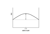
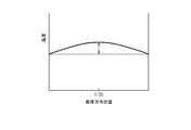
- the temperature difference in the plate thickness direction can be reduced as shown in FIG. 2 by heating the front and back surfaces of the steel plate during rolling, and the temperature is lower than ever. I thought that I could roll it stably. Thereby, when hot rolling is performed under the same conditions as before, even higher brittle crack propagation stopping characteristics can be obtained. In addition, the rolling conditions necessary for obtaining the same level of brittle crack propagation stopping characteristics can be relaxed as compared with the conventional ones.
- the present invention has been completed. That is, the gist configuration of the present invention is as follows.
- Ceq [C] + [Mn] / 6 + [Cu] / 15 + [Ni] / 15 + [Cr] / 5 + [Mo] / 5 + [V] / 5 (1) Ceq ⁇ 0.40 (2)
- the parenthesis in the formula (1) represents the content (% by mass) of the element in the parenthesis in the high-strength thick steel plate, and is 0 when the element is not contained.
- the plate thickness is 50-100mm, Kca ( ⁇ 10 ° C.) is 7000 N / mm 3/2 or more, 2.
- Kca ⁇ 10 ° C.
- the component composition is mass%, Nb: 0.005 to 0.05%, Cu: 0.01 to 0.5%, 4.
- the component composition is mass%, Mo: 0.01 to 0.5%, V: 0.001 to 0.10%, B: 0.0030% or less,
- a method for producing a high-strength thick steel plate according to any one of 1 to 6 above A heating step of heating the steel having the component composition according to any one of 1, 4, and 5 to a heating temperature of 1000 to 1200 ° C .; A hot rolling step in which the heated steel is hot rolled into a hot rolled steel sheet, The hot rolling step, Hot rolling in which the plate thickness 1/2 position is in the austenite recrystallization temperature range; The plate thickness 1/2 position includes hot rolling in the austenite non-recrystallization temperature range, A method for producing a high-strength thick steel plate, wherein the steel is heated from both front and back surfaces during the hot rolling step.
- the texture at both the plate thickness 1/2 position and the steel plate surface is appropriately controlled, so that even when the plate thickness exceeds 50 mm, the brittle crack propagation stopping property is excellent.
- a strong thick steel plate can be obtained.
- the high-strength thick steel plate of the present invention largely contributes to improving the safety of ships by applying it to deck members joined to hatch side combing in the strong deck structure of container ships and bulk carriers. It is extremely useful in industry.
- the present invention will be specifically described.
- the component composition and texture are defined as described above.
- C 0.03 to 0.20%
- C is an element that improves the strength of steel, and in the present invention, it is necessary to contain 0.03% or more in order to ensure a desired strength. However, if the C content exceeds 0.20%, the weldability is deteriorated and the toughness is also adversely affected. Therefore, the C content is 0.03 to 0.20%.
- the C content is preferably 0.05 to 0.15%.
- Si 0.03-0.5%
- Si is effective as a deoxidizing element and as a steel strengthening element. However, if the content is less than 0.03%, the effect is not obtained. On the other hand, when the Si content exceeds 0.5%, not only the surface properties of the steel are impaired, but also the toughness is extremely deteriorated. Therefore, the Si content is 0.03 to 0.5%.
- the Si content is preferably 0.04 to 0.40%.
- Mn 0.5 to 2.2% Mn is contained as a strengthening element. If the Mn content is less than 0.5%, the effect is not sufficient. On the other hand, if the Mn content exceeds 2.2%, the weldability deteriorates and the steel material cost also increases. Therefore, the Mn content is 0.5 to 2.2%.
- P 0.02% or less
- P is an inevitable impurity in steel, and as the content increases, the toughness deteriorates. Therefore, in order to maintain good toughness even in a thick steel plate having a thickness exceeding 50 mm, the P content is set to 0.02% or less.
- the P content is preferably 0.01% or less, and more preferably 0.006% or less.
- the lower limit is not limited, and may be 0%, but industrially it exceeds 0%.
- S 0.01% or less S is an unavoidable impurity in steel, and as the content increases, the toughness deteriorates. Therefore, in order to maintain good toughness even in a thick steel plate having a plate thickness exceeding 50 mm, the S content is set to 0.01% or less.
- the S content is preferably 0.005% or less, and more preferably 0.003% or less.
- the lower limit is not limited, and may be 0%, but industrially it exceeds 0%.
- Ti 0.005 to 0.03%
- Ti has the effect of forming nitrides, carbides, or carbonitrides by adding a trace amount, and making the crystal grains finer to improve the base material toughness. The effect can be obtained when the Ti content is 0.005% or more.
- the Ti content is set to 0.005 to 0.03%.
- the Ti content is preferably 0.006 to 0.028%.
- Al 0.005 to 0.080%
- Al is an element added as a deoxidizing material, and 0.005% or more must be added to obtain the effect.
- the Al content is set to 0.005 to 0.080%.
- the Al content is preferably 0.020 to 0.040%.
- N 0.0050% or less
- N is an element that combines with Al in the steel, adjusts the crystal grain size during rolling, and strengthens the steel. However, if the N content exceeds 0.0050%, the toughness deteriorates, so the N content is set to 0.0050% or less.
- the lower limit of the N content is not particularly limited, but is preferably 0.0010% or more, and more preferably 0.0015% or more.
- the component composition of the high-strength thick steel plate in one embodiment of the present invention is composed of the above elements, the remaining Fe and inevitable impurities.
- the component composition further optionally contains one or more selected from the group consisting of Nb, Cu, Ni, and Cr. Is possible.
- Nb 0.005 to 0.05% Nb precipitates as NbC during ferrite transformation or reheating, and contributes to increasing the strength.
- Nb has an effect of expanding the non-recrystallized region in rolling in the austenite region, and contributes to the refinement of ferrite, so it is also effective in improving toughness. The effect is exhibited when the content is 0.005% or more. However, when the content exceeds 0.05%, coarse NbC precipitates, which causes a decrease in toughness. Therefore, when Nb is contained, the Nb content is set to 0.005 to 0.05%.
- Cu 0.01 to 0.5%
- Cu is an element that enhances the hardenability of steel, and contributes to improving functions such as toughness, high-temperature strength, and weather resistance in addition to improving strength after rolling. These effects are exhibited by the content of 0.01% or more, but excessive content deteriorates by changing toughness and weldability. Therefore, the Cu content is set to 0.01 to 0.5%.
- Ni 0.01 to 1.5%
- Ni is an element that enhances the hardenability of steel, and contributes to functional improvements such as toughness, high-temperature strength, and weather resistance, in addition to improving strength after rolling. These effects are exhibited when the content is 0.01% or more. On the other hand, excessive inclusion causes deterioration of the toughness and weldability, and increases the cost of the alloy. Therefore, the Ni content is set to 0.01 to 1.5%.
- Cr 0.01 to 0.5% Cr, like Cu, is an element that enhances the hardenability of steel, and contributes to functional improvements such as toughness, high-temperature strength, and weather resistance in addition to improving strength after rolling. These effects are exhibited by the content of 0.01% or more, but excessive content deteriorates by changing toughness and weldability. Therefore, the Cr content is set to 0.01 to 0.5%.
- the said component composition further contains 1 or 2 or more selected from the group which consists of Mo, V, B, Ca, and REM arbitrarily further Is possible.
- Mo 0.01 to 0.5% Mo, like Cu and Cr, is an element that enhances the hardenability of steel, and contributes to functional improvements such as toughness, high-temperature strength, and weather resistance in addition to improving strength after rolling. These effects are exhibited by the content of 0.01% or more, but excessive content deteriorates by changing toughness and weldability. Therefore, the Mo content is set to 0.01 to 0.5%.
- V 0.001 to 0.10%
- V is an element that improves the strength of the steel by precipitation strengthening that precipitates as V (CN). This effect is exhibited by containing V by 0.001% or more. On the other hand, when V is contained exceeding 0.10%, toughness is rather lowered. Therefore, when V is contained, the V content is set to 0.001 to 0.10%.
- B 0.0030% or less
- B is an element having an effect of enhancing the hardenability of steel in a small amount and can be arbitrarily contained. However, if the B content exceeds 0.0030%, the toughness of the welded portion decreases. Therefore, the B content is 0.0030% or less.
- the lower limit of the B content is not particularly limited. However, when B is contained, the B content is preferably 0.0006% or more from the viewpoint of obtaining good hardenability.
- Ca 0.0050% or less
- Ca is an element having the effect of improving the toughness by refining the structure of the weld heat affected zone, and the effect of the present invention is not impaired as long as it is contained in an appropriate amount. Therefore, Ca can be contained as necessary. However, when Ca is contained excessively, coarse inclusions are formed and the toughness of the base material is deteriorated. Therefore, when Ca is contained, the Ca content is set to 0.0050% or less. On the other hand, the lower limit of the Ca content is not particularly limited. However, when Ca is added, the Ca content is preferably 0.0001% or more in order to sufficiently obtain the addition effect.
- REM 0.0100% or less REM (rare earth metal) is an element that has the effect of improving the toughness by refining the structure of the weld heat affected zone in the same way as Ca. Will not be damaged. Therefore, REM can optionally be contained. However, if REM is excessively contained, coarse inclusions are formed and the toughness of the base material is deteriorated. Therefore, when REM is contained, the REM content is set to 0.0100% or less. On the other hand, the lower limit of the REM content is not particularly limited. However, when REM is added, the REM content is preferably 0.0005% or more in order to sufficiently obtain the effect of addition.
- the carbon equivalent Ceq defined by the following formula (1) satisfies the condition of the following formula (2).
- Ceq [C] + [Mn] / 6 + [Cu] / 15 + [Ni] / 15 + [Cr] / 5 + [Mo] / 5 + [V] / 5 (1)
- the parenthesis in the above formula (1) represents the content (% by mass) of the element in the parenthesis in the high-strength thick steel plate, and is 0 when the element is not contained.
- the strength and texture strength can be maintained even in a thick steel plate having a plate thickness exceeding 50 mm.
- the upper limit of Ceq is not particularly limited, but is preferably 0.55 or less, more preferably 0.53 or less, and even more preferably 0.50 or less.
- the texture is such that the ⁇ 113 ⁇ ⁇ 110> orientation strength at the plate thickness 1/2 position is 4.0 or more and the ⁇ 113 ⁇ ⁇ 110> orientation strength at the steel plate surface is 1.7 or more.
- the texture is such that the ⁇ 113 ⁇ ⁇ 110> orientation strength at the plate thickness 1/2 position is 4.0 or more and the ⁇ 113 ⁇ ⁇ 110> orientation strength at the steel plate surface is 1.7 or more.
- the ⁇ 113 ⁇ ⁇ 110> orientation strength at the plate thickness 1/2 position is 4.1 or more, and the ⁇ 113 ⁇ ⁇ 110> orientation strength at the steel plate surface is It is preferable to set it as 1.9 or more.
- the upper limit of the ⁇ 113 ⁇ ⁇ 110> azimuth strength at the plate thickness 1/2 position is not particularly limited, and the higher the better, but generally it may be 7.0 or less. Moreover, it does not specifically limit about the upper limit of ⁇ 113 ⁇ ⁇ 110> azimuth
- the ⁇ 113 ⁇ ⁇ 110> azimuth strength at the plate thickness 1/2 position and the ⁇ 113 ⁇ ⁇ 110> azimuth strength at the steel plate surface can be determined as random strength ratios by the X-ray pole figure method, respectively. Specifically, it can be measured by the method described in the examples. In the measurement, a positional error of several percent is allowed.
- the area fraction of bainite is more preferably 90% or more.
- the upper limit of the area fraction of the bainite is not particularly limited, and may be 100%.
- the remainder other than bainite is not particularly limited and can be an arbitrary structure.
- the total area fraction of the remaining tissue is preferably 15% or less. The area fraction can be measured by the method described in Examples.
- vE Charpy absorbed energy at ⁇ 40 ° C. at a position of 1 ⁇ 4 ° C .: vE ( ⁇ 40 ° C.) is preferably 250 J or more, more preferably 280 J or more, and 300 J or more. It is more preferable.
- the upper limit of the vE ( ⁇ 40 ° C.) is not particularly limited, but is generally 420 J or less, and may be 400 J or less.
- the vE ( ⁇ 40 ° C.) at a position (depth) 5 mm from the surface of the high-strength thick steel plate is preferably 250 J or more, more preferably 280 J or more, and more preferably 300 J or more.
- the upper limit of the vE ( ⁇ 40 ° C.) is not particularly limited, but is generally 420 J or less, and may be 400 J or less.
- both the vE ( ⁇ 40 ° C.) at the position of 5 mm from the surface of the steel sheet and the position of the thickness 1/2 are obtained by heating the steel from both the front and back sides during the hot rolling process.
- the Charpy fracture surface transition temperature at a 1 ⁇ 4 thickness position is ⁇ 40 ° C. or lower.
- the lower limit of the Charpy fracture surface transition temperature is not particularly limited, but may generally be ⁇ 130 ° C. or higher.
- Kca ( ⁇ 10 ° C.) is 7000 N / mm 3/2 or more. it can.
- Kca (-10 ° C.) is preferably in the 7500N / mm 3/2 or more, more preferably, to 8000 N / mm 3/2 or more, still more preferably 9000 N / mm 3/2 or more.
- the upper limit is not particularly limited, but in general, it may be 13000 N / mm 3/2 or less.
- the value of Kca ( ⁇ 10 ° C.) can be measured by a temperature gradient type ESSO test, and specifically can be obtained by the method described in the examples.
- the tensile strength (TS) of the high-strength thick steel plate of the present invention is not particularly limited, but the tensile strength TS at the 1/4 thickness position is preferably 570 MPa or more, more preferably 580 MPa or more, More preferably, it is 590 MPa or more.
- the upper limit of TS is not particularly limited, but generally, the tensile strength TS at the 1/4 thickness position may be 700 MPa or less.
- the plate thickness of the high-strength thick steel plate of the present invention is not particularly limited, and can be an arbitrary value. However, since the effect of the present invention becomes more significant as the plate thickness increases, the plate thickness is preferably 50 mm or more, more preferably more than 50 mm, further preferably 60 mm or more, and 70 mm or more. More preferably. On the other hand, the upper limit of the plate thickness is not particularly limited, but may generally be 100 mm or less.
- the high-strength thick steel plate of the present invention can be produced by hot rolling steel having the above-described component composition under specific conditions. Specifically, the following steps (1) and (2) are sequentially performed. (1) A heating step of heating steel to a heating temperature of 1000 to 1200 ° C. (2) A hot rolling process in which the heated steel is hot rolled to form a hot rolled steel sheet. In the (2) hot rolling step, the following steps (2-1) and (2-2) are sequentially performed. (2-1) Hot rolling (recrystallization zone rolling) in which the plate thickness 1 ⁇ 2 position is in the austenite recrystallization temperature range. (2-2) Hot rolling (non-recrystallized zone rolling) in which the plate thickness 1/2 position is in the austenite non-recrystallized temperature range.
- step (3) A cooling step of cooling the hot-rolled steel sheet to a cooling stop temperature of 500 ° C. or lower at a cooling rate of 3 ° C./s or higher.
- step (4) may be optionally performed.
- Heating temperature 1000-1200 ° C
- the steel having the above composition is heated. At that time, if the heating temperature is less than 1000 ° C., sufficient rolling time in the austenite recrystallization temperature region cannot be ensured. On the other hand, when the heating temperature exceeds 1200 ° C., the austenite grains become coarse, leading to a decrease in toughness, and an oxidation loss becomes remarkable, resulting in a decrease in yield. Therefore, the heating temperature is set to 1000 to 1200 ° C. From the viewpoint of improving the toughness of the steel sheet, the heating temperature is preferably 1000 to 1170 ° C, and more preferably 1050 to 1170 ° C.
- the steel used for the heating step is not particularly limited and can be manufactured by an arbitrary method.
- a steel piece (slab) obtained by melting a molten steel having the above component composition in a converter or the like and obtaining it by continuous casting can be used.
- hot rolling is performed.
- (2-1) hot rolling (recrystallization zone rolling) is performed in the austenite recrystallization temperature range at a position where the plate thickness is 1/2, and then (2-2) plate thickness 1 / 2 position performs hot rolling (non-recrystallization zone rolling) in the austenite non-recrystallization temperature range.
- the rolling end temperature in the hot rolling step is not particularly limited, but is preferably Ar 3 point or higher.
- the cumulative rolling reduction in the above hot rolling is not particularly limited.
- the upper limit of the recrystallization temperature range cumulative rolling reduction is not particularly limited, but is preferably 60% or less from the viewpoint of rolling load.
- the cumulative reduction ratio (non-recrystallized area cumulative reduction ratio) in hot rolling in the (2-2) plate thickness 1/2 position in the austenite non-recrystallization temperature range be 45% or more.
- the upper limit of the unrecrystallized temperature range cumulative rolling reduction is not particularly limited, but is preferably 90% or less from the viewpoint of rolling load. From the viewpoint of texture control, it is preferable to control the cumulative rolling reduction in this way.
- the steel is heated from both the front and back sides during the (2) hot rolling step.
- the temperature distribution in the plate thickness direction can be controlled, and the temperature difference between the steel plate surface and the inside can be reduced.
- vE ⁇ 40 ° C.
- a position of 5 mm from the surface of the steel sheet and a position of a thickness of 1/2 can be set to 250 J or more.
- the heating from both the front and back surfaces is performed such that the temperature difference between the steel surface and the plate thickness 1/2 at the time when the heating is completed is 30 ° C. or less. Thereby, it can suppress that a ferrite produces
- the temperature difference is more preferably 20 ° C. or less, and further preferably 10 ° C. or less.
- the lower limit is not particularly limited, and may be 0 ° C. or higher.
- the timing which performs the said heating is not specifically limited, What is necessary is just in the middle of a hot rolling process.
- heating is performed before the start of non-recrystallization zone rolling, from the viewpoint of temperature control, it is preferable to start the non-recrystallization zone rolling within 30 seconds after the completion of the heating.
- the heating in the hot rolling step is not particularly limited and can be performed by any method such as induction heating or furnace heating.
- Cooling rate 3 ° C./s or more Cooling stop temperature: 500 ° C. or less
- the steel sheet that has been rolled is 500 ° C. or less at a cooling rate of 3 ° C./s or more from the viewpoint of maintaining the texture developed during rolling. It is preferable to cool to a cooling stop temperature.
- the upper limit of a cooling rate is not specifically limited, It is preferable to set it as 10 degrees C / s or less.
- the lower limit of the cooling stop temperature is not particularly limited, but is preferably 0 ° C. or higher.
- the cooling start temperature in the cooling step it is preferable that the Ar 3 point or more.
- Tempering temperature When performing tempering treatment after the Ac 1 point below the cooling step, it is preferable to perform the tempering under the following tempering temperature point Ac. This is because if the tempering temperature is higher than the Ac 1 point, the texture developed during rolling may be lost.
- the lower limit of the tempering temperature is not particularly limited, but is preferably 400 ° C. or higher.
- the temperature at the plate thickness 1/2 position is obtained by heat transfer calculation from the steel plate surface temperature measured with a radiation thermometer or calculation based on the center temperature measured in advance. Moreover, the temperature in the cooling conditions after rolling is the temperature at the plate thickness 1/2 position.
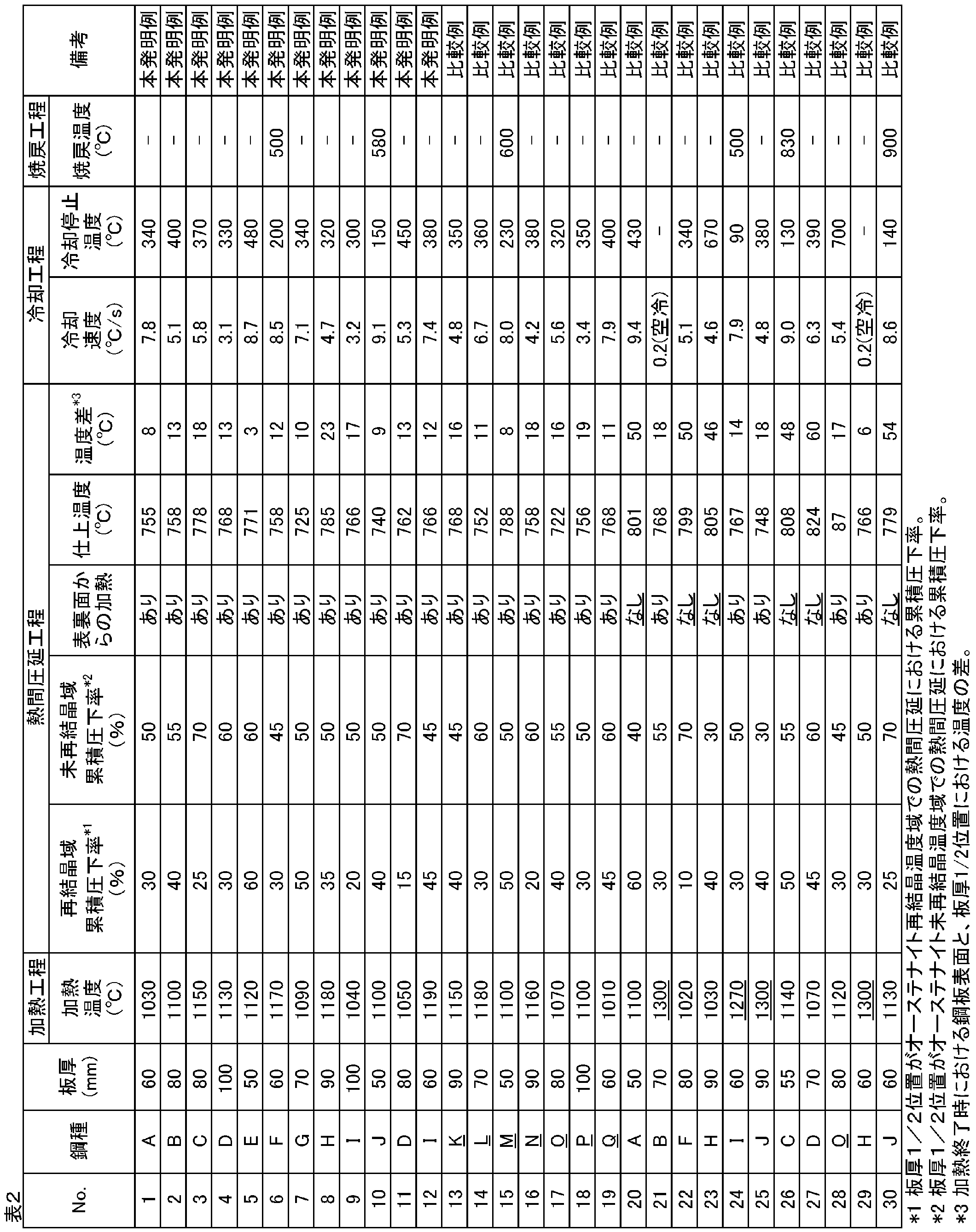
- the steel was heated from both the front and back surfaces except for some comparative examples.
- the heating was performed after completion of recrystallization zone rolling and before starting non-recrystallization zone rolling. At that time, the non-recrystallization zone rolling was started within 30 seconds from the end of heating.
- the heating was performed by furnace heating using an atmospheric furnace and induction heating by high frequency.
- the test piece used for measuring vE ( ⁇ 40 ° C.) at a position 5 mm from the surface of the steel sheet was taken from the surface of the steel sheet after removing the scale (black skin) formed on the surface of the steel sheet. did. Since the thickness of the test piece is 10 mm, the measurement position on the test piece is the center position in the thickness direction of the test piece, that is, the position of 5 mm from the steel plate surface to the plate thickness direction.
- the X-ray-diffraction measurement was implemented using the X-ray-diffraction apparatus using Mo ray source, and the (200), (110), and (211) positive electrode dot diagram was calculated
- the ratio of ⁇ 113 ⁇ ⁇ 110> orientation strength to random strength was calculated by calculating a three-dimensional crystal orientation density function from the obtained positive electrode dot diagram.
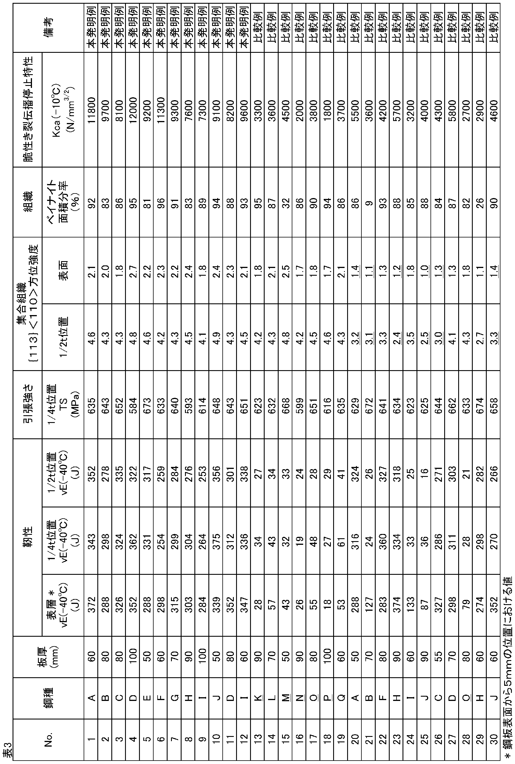
- the high-strength thick steel plate that satisfies the conditions of the present invention has a vE ( ⁇ 40 ° C.) at a position of 5 mm from the steel plate surface, a thickness of 1/2, and a thickness of 1/4.
- Kca ( ⁇ 10 ° C.) was 7000 N / mm 3/2 or more and had excellent brittle crack propagation stopping characteristics.
- the high strength thick steel plate of the comparative example not satisfying the conditions of the present invention was inferior in at least one of vE ( ⁇ 40 ° C.) and Kca ( ⁇ 10 ° C.) at the 1/4 thickness position.
Landscapes
- Chemical & Material Sciences (AREA)
- Engineering & Computer Science (AREA)
- Mechanical Engineering (AREA)
- Materials Engineering (AREA)
- Metallurgy (AREA)
- Organic Chemistry (AREA)
- Physics & Mathematics (AREA)
- Thermal Sciences (AREA)
- Crystallography & Structural Chemistry (AREA)
- Heat Treatment Of Steel (AREA)
Abstract
Description
C :0.03~0.20%、
Si:0.03~0.5%、
Mn:0.5~2.2%、
P :0.02%以下、
S :0.01%以下、
Ti:0.005~0.03%、
Al:0.005~0.080%、および
N :0.0050%以下を含有し、
残部がFeおよび不可避的不純物からなり、
かつ下記(1)式で定義されるCeqが下記(2)式の条件を満足する成分組成を有し、
板厚1/2位置における{113}<110>方位強度が4.0以上、鋼板表面における{113}<110>方位強度が1.7以上の集合組織を有する、高強度厚鋼板。
記
Ceq=[C]+[Mn]/6+[Cu]/15+[Ni]/15+[Cr]/5+[Mo]/5+[V]/5…(1)
Ceq≧0.40…(2)
ここで、上記(1)式における括弧は、前記高強度厚鋼板における該括弧内の元素の含有量(質量%)を表し、該元素が含有されていない場合には0とする
Kca(-10℃)が7000N/mm3/2以上、
板厚1/4位置におけるvE(-40℃)が250J以上、かつ
板厚1/4位置における引張強さTSが570MPa以上である、上記1に記載の高強度厚鋼板。
Nb:0.005~0.05%、
Cu:0.01~0.5%、
Ni:0.01~1.5%、および
Cr:0.01~0.5%からなる群より選択される1または2以上をさらに含有する、上記1~3のいずれか一項に記載の高強度厚鋼板。
Mo:0.01~0.5%、
V :0.001~0.10%、
B :0.0030%以下、
Ca:0.0050%以下、および
REM:0.0100%以下からなる群より選択される1または2以上をさらに含有する、上記1~4のいずれか一項に記載の高強度厚鋼板。
上記1、4、および5のいずれか一項に記載の成分組成を有する鋼を1000~1200℃の加熱温度に加熱する加熱工程と、
加熱された前記鋼を熱間圧延して熱延鋼板とする熱間圧延工程とを有し、
前記熱間圧延工程が、
板厚1/2位置がオーステナイト再結晶温度域での熱間圧延と、
板厚1/2位置がオーステナイト未再結晶温度域での熱間圧延とを含み、
前記熱間圧延工程の間に、前記鋼を表裏の両面から加熱する、高強度厚鋼板の製造方法。
まず、本発明において鋼の成分組成を上記のように限定する理由を説明する。なお、成分組成に関する「%」表示は、特に断らない限り「質量%」を意味するものとする。
Cは、鋼の強度を向上する元素であり、本発明では、所望の強度を確保するためには0.03%以上の含有を必要とする。しかし、C含有量が0.20%を超えると、溶接性が劣化するばかりか靭性にも悪影響がある。このため、C含有量は、0.03~0.20%とする。なお、C含有量は0.05~0.15%とすることが好ましい。
Siは、脱酸元素として、また、鋼の強化元素として有効であるが、0.03%未満の含有量ではその効果がない。一方、Si含有量が0.5%を超えると、鋼の表面性状を損なうばかりか、靭性が極端に劣化する。従って、Si含有量は0.03~0.5%とする。Si含有量は0.04~0.40%とすることが好ましい。
Mnは、強化元素として含有される。Mn含有量が0.5%より少ないとその効果が十分でない。一方、Mn含有量が2.2%を超えると溶接性が劣化することに加え、鋼材コストも上昇する。そのため、Mn含有量は、0.5~2.2%とする。
Pは、鋼中の不可避的不純物であり、含有量が多くなると靭性が劣化してしまう。そのため、板厚が50mm超えるような厚鋼板においても良好な靭性を保つために、P含有量を0.02%以下とする。P含有量は0.01%以下とすることが好ましく、0.006%以下とすることがより好ましい。一方、下限については限定されず、0%であってもよいが、工業的には0%超である。
Sは、鋼中の不可避的不純物であり、含有量が多くなると靭性が劣化してしまう。そのため、板厚が50mm超えるような厚鋼板においても良好な靭性を保つために、S含有量を0.01%以下とする。S含有量は0.005%以下とすることが好ましく、0.003%以下とすることがより好ましい。一方、下限については限定されず、0%であってもよいが、工業的には0%超である。
Tiは、微量の含有により、窒化物、炭化物、あるいは炭窒化物を形成し、結晶粒を微細化して母材靭性を向上させる効果を有する。前記効果は、Ti含有量が0.005%以上であれば得ることができる。一方、Ti含有量が0.03%を超えると、母材および溶接熱影響部における靭性が低下する。そのため、Ti含有量は0.005~0.03%とする。Ti含有量は0.006~0.028%とすることが好ましい。
Alは、脱酸材として添加される元素であり、その効果を得るためには0.005%以上の添加が必要である。一方、Al含有量が0.080%を超えると、靭性が低下するとともに、溶接した場合に溶接金属部の靭性が低下する。このため、Al含有量は、0.005~0.080%とする。なお、Al含有量は、0.020~0.040%とすることが好ましい。
Nは、鋼中のAlと結合し、圧延加工時の結晶粒径を調整し、鋼を強化する元素である。しかし、N含有量が0.0050%を超えると靭性が劣化するため、N含有量は0.0050%以下とする。一方、N含有量の下限は特に限定されないが、0.0010%以上とすることが好ましく、0.0015%以上とすることがより好ましい。
Nbは、NbCとしてフェライト変態時あるいは再加熱時に析出し、高強度化に寄与する。また、Nbは、オーステナイト域の圧延において未再結晶域を拡大させる効果を有し、フェライトの細粒化に寄与するので、靭性の改善にも有効である。その効果は0.005%以上の含有により発揮されるが、0.05%を超えて含有すると、粗大なNbCが析出することにより、かえって靭性の低下を招く。そのため、Nbを含有する場合、Nb含有量を0.005~0.05%とする。
Cuは、鋼の焼入れ性を高める元素であり、圧延後の強度向上に加え、靭性、高温強度、耐候性などの機能向上に寄与する。これらの効果は、0.01%以上の含有によって発揮されるが、過度の含有は靭性や溶接性をかえって劣化させる。そのため、Cu含有量は0.01~0.5%とする。
Niは、鋼の焼入れ性を高める元素であり、圧延後の強度向上に加え、靭性、高温強度、耐候性などの機能向上に寄与する。これらの効果は、0.01%以上の含有によって発揮される。一方、過度の含有は靭性や溶接性をかえって劣化させることに加え、合金のコスト増加を招く。そのため、Ni含有量は0.01~1.5%とする。
Crは、Cuと同様に、鋼の焼入れ性を高める元素であり、圧延後の強度向上に加え、靭性、高温強度、耐候性などの機能向上に寄与する。これらの効果は、0.01%以上の含有によって発揮されるが、過度の含有は靭性や溶接性をかえって劣化させる。そのため、Cr含有量は0.01~0.5%とする。
Moは、CuやCrと同様に、鋼の焼入れ性を高める元素であり、圧延後の強度向上に加え、靭性、高温強度、耐候性などの機能向上に寄与する。これらの効果は、0.01%以上の含有によって発揮されるが、過度の含有は靭性や溶接性をかえって劣化させる。そのため、Mo含有量は0.01~0.5%とする。
Vは、V(CN)として析出する析出強化によって、鋼の強度を向上させる元素である。この効果はVを0.001%以上含有させることにより発揮される。一方、Vを0.10%を超えて含有すると、かえって靭性が低下する。このため、Vを含有させる場合には、V含有量を0.001~0.10%とする。
Bは、微量で鋼の焼入れ性を高める効果を有する元素であり、任意に含有させることができる。しかし、B含有量が0.0030%を超えると、溶接部の靭性が低下する。そのため、B含有量を0.0030%以下とする。なお、B含有量の下限は特に限定されないが、Bを含有させる場合、良好な焼入れ性を得るという観点からは、B含有量を0.0006%以上とすることが好ましい。
Caは、溶接熱影響部の組織を微細化して靭性を向上させる効果を有する元素であり、適量の含有であれば本発明の効果が損なわれることはない。したがって、必要に応じてCaを含有することができる。しかし、過度にCaを含有すると、粗大な介在物を形成して母材の靭性を劣化させる。そのため、Caを含有させる場合には、Ca含有量を0.0050%以下とする。一方、Ca含有量の下限値は特に限定されないが、Caを添加する場合、添加効果を十分に得るためにはCa含有量を0.0001%以上とすることが好ましい。
REM(希土類金属)は、Caと同様に、溶接熱影響部の組織を微細化して靭性を向上させる効果を有する元素であり、適量の含有であれば本発明の効果が損なわれることはない。したがって、任意にREMを含有することができる。しかし、過度にREMを含有すると、粗大な介在物を形成して母材の靭性を劣化させる。そのため、REMを含有させる場合には、REM含有量を0.0100%以下とする。一方、REM含有量の下限は特に限定されないが、REMを添加する場合、添加効果を十分に得るためにはREM含有量を0.0005%以上とすることが好ましい。
さらに、上記成分組成は、下記(1)式で定義される炭素当量Ceqが下記(2)式の条件を満足するものである。
Ceq=[C]+[Mn]/6+[Cu]/15+[Ni]/15+[Cr]/5+[Mo]/5+[V]/5…(1)
Ceq≧0.40…(2)
ここで、上記(1)式における括弧は、高強度厚鋼板における該括弧内の元素の含有量(質量%)を表し、該元素が含有されていない場合には0とする。
本発明では、圧延方向または圧延直角方向など板面に平行な方向に伝播するき裂に対するき裂伝播停止特性を向上させるために、板厚1/2位置および鋼板表面における{113}<110>方位強度を規定する。板厚1/2位置および鋼板表面において、{113}<110>方位を発達させると、き裂進展に先立ち微視的なクラックが発生してき裂進展の抵抗となる。なお、ここで「板厚1/2位置」とは板厚方向における中央の位置を意味し、「鋼板表面」とは、スケールを除去した後の鋼板の表面から0.5mmの深さの位置を意味する。
板厚1/2位置におけるベイナイトの面積分率を85%以上とすることが好ましい。組織をこのように制御することにより 脆性き裂伝播特性に有利な{113}<110>方位を高めることができる。なお、前記ベイナイトの面積分率は、90%以上とすることがより好ましい。一方、前記ベイナイトの面積分率の上限は特に限定されず、100%であってよい。なお、ベイナイト以外の残部は、特に限定されることなく、任意の組織とすることができる。それら残部組織の面積分率の合計は、15%以下とすることが好ましい。前記面積分率は、実施例に記載の方法で測定することができる。
上記のように成分組成と集合組織を制御することにより、優れた母材靭性を有する高強度厚鋼板を得ることができる。優れた母材靭性を有することは、き裂の進展を抑制する上で重要である。具体的には、板厚1/4位置での、-40℃におけるシャルピー吸収エネルギー:vE(-40℃)を250J以上とすることが好ましく、280J以上とすることがより好ましく、300J以上とすることがより好ましい。一方、前記vE(-40℃)の上限は特に限定されないが、一般的には、420J以下であってよく、400J以下であってもよい。
上述したように、本発明の高強度厚鋼板においては集合組織を制御することによってKca(-10℃)が7000N/mm3/2以上という、優れた脆性き裂伝播停止特性を実現することができる。Kca(-10℃)は、7500N/mm3/2以上とすることが好ましく、8000N/mm3/2以上とすることがより好ましく、9000N/mm3/2以上とすることがさらに好ましい。一方、Kca(-10℃)の値は高いほど好ましいため、その上限は特に限定されないが、一般的には、13000N/mm3/2以下であってよい。なお、前記Kca(-10℃)の値は温度勾配型ESSO試験によって測定することができ、具体的には実施例に記載した方法で得ることができる。
本発明の高強度厚鋼板の引張強さ(TS)は、特に限定されないが、板厚1/4位置における引張強さTSを570MPa以上とすることが好ましく、580MPa以上とすることがより好ましく、590MPa以上とすることがさらに好ましい。一方、TSの上限についても特に限定されないが、一般的には、板厚1/4位置における引張強さTSが700MPa以下であってよい。
本発明の高強度厚鋼板の板厚は特に限定されず、任意の値とすることができる。しかし、板厚が厚いほど本発明の効果が顕著となるため、板厚は、50mm以上とすることが好ましく、50mm超とすることがより好ましく、60mm以上とすることがさらに好ましく、70mm以上とすることがさらに好ましい。一方、板厚の上限についても特に限定されないが、一般的には100mm以下であってよい。
次に、本発明の一実施形態における高強度厚鋼板の製造方法を説明する。
(1)鋼を1000~1200℃の加熱温度に加熱する加熱工程。
(2)加熱された前記鋼を熱間圧延して熱延鋼板とする熱間圧延工程。
そして、前記(2)熱間圧延工程においては、次の(2-1)および(2-2)の工程を順次行う。
(2-1)板厚1/2位置がオーステナイト再結晶温度域での熱間圧延(再結晶域圧延)。
(2-2)板厚1/2位置がオーステナイト未再結晶温度域での熱間圧延(未再結晶域圧延)。
(3)前記熱延鋼板を、3℃/s以上の冷却速度で、500℃以下の冷却停止温度まで冷却する冷却工程。
(4)前記冷却工程で冷却された熱延鋼板を、Ac1点以下の焼戻温度で焼戻す焼戻し工程。
加熱温度:1000~1200℃
熱間圧延に先立って、上記成分組成を有する鋼を加熱する。その際、加熱温度が1000℃未満では、オーステナイト再結晶温度域における圧延時間を十分に確保することができない。一方、加熱温度が1200℃超では、オーステナイト粒が粗大化し、靭性の低下を招くばかりか、酸化ロスが顕著となって歩留が低下する。そのため、加熱温度は1000~1200℃とする。なお、鋼板の靭性向上の観点からは、前記加熱温度を1000~1170℃とすることが好ましく、1050~1170℃とすることがより好ましい。
次いで、熱間圧延を行う。熱間圧延工程においては、まず、(2-1)板厚1/2位置がオーステナイト再結晶温度域での熱間圧延(再結晶域圧延)を行い、次いで、(2-2)板厚1/2位置がオーステナイト未再結晶温度域での熱間圧延(未再結晶域圧延)を行う。前記熱間圧延工程における圧延終了温度は、特に限定されないが、Ar3点以上とすることが好ましい。
冷却速度:3℃/s以上
冷却停止温度:500℃以下
圧延が終了した鋼板は、圧延時に発達させた集合組織の保持という観点からは、3℃/s以上の冷却速度で、500℃以下の冷却停止温度まで冷却することが好ましい。冷却速度の上限は特に限定されないが、10℃/s以下とすることが好ましい。また、冷却停止温度の下限は特に限定されないが、0℃以上とすることが好ましい。また、前記冷却工程における冷却開始温度は、Ar3点以上とすることが好ましい。
焼戻温度:Ac1点以下
前記冷却工程の後に焼戻処理を行う場合は、Ac1点以下の焼戻し温度で焼戻しを行うことが好ましい。焼戻温度がAc1点より高いと、圧延時に発達させた集合組織が失われる場合があるためである。焼戻し温度の下限は特に限定されないが、400℃以上とすることが好ましい。
次に、本発明の実施例について説明する。
表1に示す各成分組成を有する溶鋼を転炉で溶製し、連続鋳造法でスラブとした。次いで、前記スラブを加熱した後、板厚:50~100mmとなるよう熱間圧延した。前記加熱と熱間圧延の条件は、表2に示した通りとした。その後、表2に示した条件で冷却を行い、その後、放冷して高強度厚鋼板を得た。一部の鋼板については、冷却後に表2に示した温度で焼戻しを行った。

得られた高強度厚鋼板の靭性を評価するために、シャルピー衝撃試験を行って、各鋼板の(1)鋼板表面から5mmの位置、(2)板厚1/4位置、および(3)板厚1/2位置の3カ所の、-40℃におけるシャルピー吸収エネルギーvE(-40℃)を測定した。前記シャルピー衝撃試験には、JIS(日本工業規格)に規定された4号衝撃試験片(長さ55mm、幅10mm、厚さ10mm)を用い、前記試験片は、該試験片の長手方向が鋼板の圧延方向と平行となるように採取した。なお、前記鋼板表面から5mmの位置におけるvE(-40℃)を測定するために用いる試験片は、鋼板の表面に形成されているスケール(黒皮)を除去した後、該鋼板の表面から採取した。試験片の厚さは10mmであるから、前記試験片における測定位置は、該試験片の厚さ方向の中心位置、すなわち、鋼板表面から板厚方向に5mmの位置となる。
得られた高強度厚鋼板の板厚1/4位置から、試験片の長手方向が圧延方向と垂直になるように、JIS 4号試験片を採取した。前記試験片を用いて、JIS Z 2241の規定に準拠して引張試験を行い、板厚1/4位置における引張強さ(TS)を求めた。
得られた高強度厚鋼板の集合組織を評価するため、(1)板厚1/2位置および(2)鋼板表面における{113}<110>方位強度を、以下の方法で測定した。まず、前記鋼板の表面に形成されているスケールを除去した後、(1)板厚1/2位置および(2)鋼板の表面から0.5mmの深さの位置が測定位置となるように、板厚厚さ1mmのサンプルを採取した。次いで、採取されたサンプルの板面に平行な面を機械研磨・電解研磨することにより、X線回折用の試験片を用意した。なお、板厚表面のサンプルについては、鋼板の表面に近い側の面を研磨した。得られた試験片のそれぞれについて、Mo線源を用いたX線回折装置を使用してX線回折測定を実施し、(200)、(110)、および(211)正極点図を求めた。得られた正極点図から3次元結晶方位密度関数を算出することによって、{113}<110>方位強度のランダム強度に対する比を算出した。
圧延方向と平行な面が観察面となるように、板厚1/2位置から試料を採取した。前記試料の表面を鏡面研磨した後、エッチングにより現出させた金属組織の光学顕微鏡写真を撮影し、画像解析によりベイナイトの面積分率を評価した。
脆性き裂伝播停止特性を評価するため、温度勾配型ESSO試験を行い、前記高強度厚鋼板の-10℃におけるKca値(以下、Kca(-10℃)とも記す)を求めた。前記温度勾配型ESSO試験には、全厚試験片を用いた。
Claims (11)
- 質量%で、
C :0.03~0.20%、
Si:0.03~0.5%、
Mn:0.5~2.2%、
P :0.02%以下、
S :0.01%以下、
Ti:0.005~0.03%、
Al:0.005~0.080%、および
N :0.0050%以下を含有し、
残部がFeおよび不可避的不純物からなり、
かつ下記(1)式で定義されるCeqが下記(2)式の条件を満足する成分組成を有し、
板厚1/2位置における{113}<110>方位強度が4.0以上、鋼板表面における{113}<110>方位強度が1.7以上の集合組織を有する、高強度厚鋼板。
記
Ceq=[C]+[Mn]/6+[Cu]/15+[Ni]/15+[Cr]/5+[Mo]/5+[V]/5…(1)
Ceq≧0.40…(2)
ここで、上記(1)式における括弧は、前記高強度厚鋼板における該括弧内の元素の含有量(質量%)を表し、該元素が含有されていない場合には0とする - 板厚が50~100mmであり、
Kca(-10℃)が7000N/mm3/2以上、
板厚1/4位置におけるvE(-40℃)が250J以上、かつ
板厚1/4位置における引張強さTSが570MPa以上である、請求項1に記載の高強度厚鋼板。 - 板厚1/2位置における組織に占めるベイナイトの面積分率が85%以上である、請求項1または2に記載の高強度厚鋼板。
- 前記成分組成が、質量%で、
Nb:0.005~0.05%、
Cu:0.01~0.5%、
Ni:0.01~1.5%、および
Cr:0.01~0.5%からなる群より選択される1または2以上をさらに含有する、請求項1~3のいずれか一項に記載の高強度厚鋼板。 - 前記成分組成が、質量%で、
Mo:0.01~0.5%、
V :0.001~0.10%、
B :0.0030%以下、
Ca:0.0050%以下、および
REM:0.0100%以下からなる群より選択される1または2以上をさらに含有する、請求項1~4のいずれか一項に記載の高強度厚鋼板。 - 鋼板表面から5mm位置と板厚1/2位置とにおけるvE(-40℃)が、いずれも250J以上である、請求項1~5のいずれか一項に記載の高強度厚鋼板。
- 請求項1~6のいずれか一項に記載の高強度厚鋼板の製造方法であって、
請求項1、4、および5のいずれか一項に記載の成分組成を有する鋼を1000~1200℃の加熱温度に加熱する加熱工程と、
加熱された前記鋼を熱間圧延して熱延鋼板とする熱間圧延工程とを有し、
前記熱間圧延工程が、
板厚1/2位置がオーステナイト再結晶温度域での熱間圧延と、
板厚1/2位置がオーステナイト未再結晶温度域での熱間圧延とを含み、
前記熱間圧延工程の間に、前記鋼を表裏の両面から加熱する、高強度厚鋼板の製造方法。 - 前記熱延鋼板を、3℃/s以上の冷却速度で、500℃以下の冷却停止温度まで冷却する冷却工程をさらに有する、請求項7に記載の高強度厚鋼板の製造方法。
- 前記冷却工程で冷却された熱延鋼板を、Ac1点以下の焼戻温度で焼戻す焼戻し工程をさらに有する、請求項8に記載の高強度厚鋼板の製造方法。
- 前記表裏の両面からの加熱が終了した時点における前記鋼の表面と板厚1/2位置における温度差を30℃以下とする、請求項7~9のいずれか一項に記載の高強度厚鋼板の製造方法。
- 前記表裏の両面からの加熱を、前記板厚1/2位置がオーステナイト未再結晶温度域での熱間圧延の開始より前に行う、請求項7~10のいずれか一項に記載の高強度厚鋼板の製造方法。
Priority Applications (3)
| Application Number | Priority Date | Filing Date | Title |
|---|---|---|---|
| JP2018532938A JP6593541B2 (ja) | 2016-08-09 | 2017-07-28 | 高強度厚鋼板およびその製造方法 |
| KR1020197006739A KR102239631B1 (ko) | 2016-08-09 | 2017-07-28 | 고강도 후강판 및 그의 제조 방법 |
| CN201780049245.5A CN109563591A (zh) | 2016-08-09 | 2017-07-28 | 高强度厚钢板及其制造方法 |
Applications Claiming Priority (2)
| Application Number | Priority Date | Filing Date | Title |
|---|---|---|---|
| JP2016156722 | 2016-08-09 | ||
| JP2016-156722 | 2016-08-09 |
Publications (1)
| Publication Number | Publication Date |
|---|---|
| WO2018030186A1 true WO2018030186A1 (ja) | 2018-02-15 |
Family
ID=61162053
Family Applications (1)
| Application Number | Title | Priority Date | Filing Date |
|---|---|---|---|
| PCT/JP2017/027513 Ceased WO2018030186A1 (ja) | 2016-08-09 | 2017-07-28 | 高強度厚鋼板およびその製造方法 |
Country Status (5)
| Country | Link |
|---|---|
| JP (1) | JP6593541B2 (ja) |
| KR (1) | KR102239631B1 (ja) |
| CN (1) | CN109563591A (ja) |
| TW (1) | TWI650431B (ja) |
| WO (1) | WO2018030186A1 (ja) |
Cited By (1)
| Publication number | Priority date | Publication date | Assignee | Title |
|---|---|---|---|---|
| WO2025013927A1 (ja) * | 2023-07-11 | 2025-01-16 | 日本製鉄株式会社 | 鋼板及び鋼板の製造方法 |
Families Citing this family (2)
| Publication number | Priority date | Publication date | Assignee | Title |
|---|---|---|---|---|
| EP4032993B1 (en) * | 2019-09-20 | 2024-10-30 | JFE Steel Corporation | Thick steel sheet, and method for producing same |
| CN116194602A (zh) * | 2020-11-05 | 2023-05-30 | 杰富意钢铁株式会社 | 钢板及其制造方法 |
Citations (5)
| Publication number | Priority date | Publication date | Assignee | Title |
|---|---|---|---|---|
| JP2008169468A (ja) * | 2006-12-14 | 2008-07-24 | Nippon Steel Corp | 脆性き裂伝播停止性能に優れた高強度厚鋼板 |
| WO2013099318A1 (ja) * | 2011-12-27 | 2013-07-04 | Jfeスチール株式会社 | 脆性亀裂伝播停止特性に優れた構造用高強度厚鋼板およびその製造方法 |
| WO2013099177A1 (ja) * | 2011-12-27 | 2013-07-04 | Jfeスチール株式会社 | 脆性き裂伝播停止特性に優れた構造用高強度厚鋼板およびその製造方法 |
| JP2013151743A (ja) * | 2011-12-27 | 2013-08-08 | Jfe Steel Corp | 大入熱溶接部の靭性および脆性き裂伝播停止特性に優れた高強度厚鋼板およびその製造方法 |
| WO2014155440A1 (ja) * | 2013-03-26 | 2014-10-02 | Jfeスチール株式会社 | 脆性亀裂伝播停止特性に優れた大入熱溶接用高強度厚鋼板およびその製造方法 |
Family Cites Families (6)
| Publication number | Priority date | Publication date | Assignee | Title |
|---|---|---|---|---|
| JPS548349A (en) | 1977-06-22 | 1979-01-22 | Mitsubishi Electric Corp | Elevator door device |
| JP2659661B2 (ja) | 1993-01-06 | 1997-09-30 | 新日本製鐵株式会社 | 継手部の脆性破壊伝播停止性能の優れた溶接用構造用鋼とその製造方法 |
| JPH07100814A (ja) | 1993-10-04 | 1995-04-18 | Sekisui Chem Co Ltd | セメント成形品の製造方法 |
| JP3467767B2 (ja) | 1998-03-13 | 2003-11-17 | Jfeスチール株式会社 | 脆性亀裂伝播停止特性に優れた鋼材およびその製造方法 |
| JP4077167B2 (ja) | 2001-02-28 | 2008-04-16 | 株式会社神戸製鋼所 | アレスト特性に優れた鋼板およびその製法 |
| RU2587003C2 (ru) * | 2012-01-05 | 2016-06-10 | Ниппон Стил Энд Сумитомо Метал Корпорейшн | Горячекатаный стальной лист и способ его изготовления |
-
2017
- 2017-07-28 JP JP2018532938A patent/JP6593541B2/ja active Active
- 2017-07-28 KR KR1020197006739A patent/KR102239631B1/ko active Active
- 2017-07-28 WO PCT/JP2017/027513 patent/WO2018030186A1/ja not_active Ceased
- 2017-07-28 CN CN201780049245.5A patent/CN109563591A/zh active Pending
- 2017-08-07 TW TW106126535A patent/TWI650431B/zh active
Patent Citations (5)
| Publication number | Priority date | Publication date | Assignee | Title |
|---|---|---|---|---|
| JP2008169468A (ja) * | 2006-12-14 | 2008-07-24 | Nippon Steel Corp | 脆性き裂伝播停止性能に優れた高強度厚鋼板 |
| WO2013099318A1 (ja) * | 2011-12-27 | 2013-07-04 | Jfeスチール株式会社 | 脆性亀裂伝播停止特性に優れた構造用高強度厚鋼板およびその製造方法 |
| WO2013099177A1 (ja) * | 2011-12-27 | 2013-07-04 | Jfeスチール株式会社 | 脆性き裂伝播停止特性に優れた構造用高強度厚鋼板およびその製造方法 |
| JP2013151743A (ja) * | 2011-12-27 | 2013-08-08 | Jfe Steel Corp | 大入熱溶接部の靭性および脆性き裂伝播停止特性に優れた高強度厚鋼板およびその製造方法 |
| WO2014155440A1 (ja) * | 2013-03-26 | 2014-10-02 | Jfeスチール株式会社 | 脆性亀裂伝播停止特性に優れた大入熱溶接用高強度厚鋼板およびその製造方法 |
Cited By (1)
| Publication number | Priority date | Publication date | Assignee | Title |
|---|---|---|---|---|
| WO2025013927A1 (ja) * | 2023-07-11 | 2025-01-16 | 日本製鉄株式会社 | 鋼板及び鋼板の製造方法 |
Also Published As
| Publication number | Publication date |
|---|---|
| JP6593541B2 (ja) | 2019-10-23 |
| CN109563591A (zh) | 2019-04-02 |
| KR20190035875A (ko) | 2019-04-03 |
| TW201812046A (zh) | 2018-04-01 |
| JPWO2018030186A1 (ja) | 2018-11-29 |
| KR102239631B1 (ko) | 2021-04-12 |
| TWI650431B (zh) | 2019-02-11 |
Similar Documents
| Publication | Publication Date | Title |
|---|---|---|
| JP5304925B2 (ja) | 脆性亀裂伝播停止特性に優れた構造用高強度厚鋼板およびその製造方法 | |
| JP5733425B2 (ja) | 脆性き裂伝播停止特性に優れた高強度厚鋼板およびその製造方法 | |
| JP5434145B2 (ja) | 脆性亀裂伝播停止特性に優れた構造用高強度厚鋼板およびその製造方法 | |
| JP6536514B2 (ja) | 脆性亀裂伝播停止特性に優れた構造用高強度厚鋼板およびその製造方法 | |
| TWI500774B (zh) | High-strength steel sheet for high-heat input welding for high-strength steel sheet and its manufacturing method | |
| JP5304924B2 (ja) | 脆性亀裂伝播停止特性に優れた構造用高強度厚鋼板およびその製造方法 | |
| JP5812193B2 (ja) | 脆性き裂伝播停止特性に優れた構造用高強度厚鋼板およびその製造方法 | |
| JP6112265B2 (ja) | 高強度極厚鋼板およびその製造方法 | |
| JP5733424B2 (ja) | 脆性き裂伝播停止特性に優れた構造用高強度厚鋼板およびその製造方法 | |
| JP6593541B2 (ja) | 高強度厚鋼板およびその製造方法 | |
| JP5949113B2 (ja) | 脆性き裂伝播停止特性に優れた構造用高強度厚鋼板およびその製造方法 | |
| WO2018030171A1 (ja) | 高強度厚鋼板およびその製造方法 | |
| JP2013129885A (ja) | 脆性亀裂伝播停止特性に優れた高強度厚鋼板の製造方法 | |
| JP6338022B2 (ja) | 脆性き裂伝播停止特性に優れた高強度極厚鋼板およびその製造方法 | |
| JP6274375B1 (ja) | 高強度厚鋼板およびその製造方法 | |
| JP6504131B2 (ja) | 高強度厚鋼板およびその製造方法 | |
| JP2013133543A (ja) | 厚鋼板及び厚鋼板の製造方法 | |
| CN114245831B (zh) | 具有优异的低温韧性和ctod特性的薄钢板及用于制造其的方法 | |
| JP5949114B2 (ja) | 脆性き裂伝播停止特性に優れた構造用高強度厚鋼板の製造方法 |
Legal Events
| Date | Code | Title | Description |
|---|---|---|---|
| WWE | Wipo information: entry into national phase |
Ref document number: 2018532938 Country of ref document: JP |
|
| 121 | Ep: the epo has been informed by wipo that ep was designated in this application |
Ref document number: 17839259 Country of ref document: EP Kind code of ref document: A1 |
|
| NENP | Non-entry into the national phase |
Ref country code: DE |
|
| ENP | Entry into the national phase |
Ref document number: 20197006739 Country of ref document: KR Kind code of ref document: A |
|
| 122 | Ep: pct application non-entry in european phase |
Ref document number: 17839259 Country of ref document: EP Kind code of ref document: A1 |