WO2018029899A1 - Seat frame - Google Patents
Seat frame Download PDFInfo
- Publication number
- WO2018029899A1 WO2018029899A1 PCT/JP2017/013793 JP2017013793W WO2018029899A1 WO 2018029899 A1 WO2018029899 A1 WO 2018029899A1 JP 2017013793 W JP2017013793 W JP 2017013793W WO 2018029899 A1 WO2018029899 A1 WO 2018029899A1
- Authority
- WO
- WIPO (PCT)
- Prior art keywords
- reinforcing portion
- frame
- seat
- reinforcing
- side frame
- Prior art date
Links
Images


Classifications
-
- B—PERFORMING OPERATIONS; TRANSPORTING
- B60—VEHICLES IN GENERAL
- B60N—SEATS SPECIALLY ADAPTED FOR VEHICLES; VEHICLE PASSENGER ACCOMMODATION NOT OTHERWISE PROVIDED FOR
- B60N2/00—Seats specially adapted for vehicles; Arrangement or mounting of seats in vehicles
- B60N2/24—Seats specially adapted for vehicles; Arrangement or mounting of seats in vehicles for particular purposes or particular vehicles
- B60N2/42—Seats specially adapted for vehicles; Arrangement or mounting of seats in vehicles for particular purposes or particular vehicles the seat constructed to protect the occupant from the effect of abnormal g-forces, e.g. crash or safety seats
- B60N2/427—Seats or parts thereof displaced during a crash
- B60N2/42727—Seats or parts thereof displaced during a crash involving substantially rigid displacement
- B60N2/42745—Seats or parts thereof displaced during a crash involving substantially rigid displacement of the back-rest
-
- B—PERFORMING OPERATIONS; TRANSPORTING
- B60—VEHICLES IN GENERAL
- B60N—SEATS SPECIALLY ADAPTED FOR VEHICLES; VEHICLE PASSENGER ACCOMMODATION NOT OTHERWISE PROVIDED FOR
- B60N2/00—Seats specially adapted for vehicles; Arrangement or mounting of seats in vehicles
- B60N2/68—Seat frames
- B60N2/682—Joining means
-
- B—PERFORMING OPERATIONS; TRANSPORTING
- B60—VEHICLES IN GENERAL
- B60N—SEATS SPECIALLY ADAPTED FOR VEHICLES; VEHICLE PASSENGER ACCOMMODATION NOT OTHERWISE PROVIDED FOR
- B60N2/00—Seats specially adapted for vehicles; Arrangement or mounting of seats in vehicles
- B60N2/24—Seats specially adapted for vehicles; Arrangement or mounting of seats in vehicles for particular purposes or particular vehicles
- B60N2/42—Seats specially adapted for vehicles; Arrangement or mounting of seats in vehicles for particular purposes or particular vehicles the seat constructed to protect the occupant from the effect of abnormal g-forces, e.g. crash or safety seats
- B60N2/427—Seats or parts thereof displaced during a crash
- B60N2/42709—Seats or parts thereof displaced during a crash involving residual deformation or fracture of the structure
-
- B—PERFORMING OPERATIONS; TRANSPORTING
- B60—VEHICLES IN GENERAL
- B60N—SEATS SPECIALLY ADAPTED FOR VEHICLES; VEHICLE PASSENGER ACCOMMODATION NOT OTHERWISE PROVIDED FOR
- B60N2/00—Seats specially adapted for vehicles; Arrangement or mounting of seats in vehicles
- B60N2/68—Seat frames
-
- B—PERFORMING OPERATIONS; TRANSPORTING
- B60—VEHICLES IN GENERAL
- B60N—SEATS SPECIALLY ADAPTED FOR VEHICLES; VEHICLE PASSENGER ACCOMMODATION NOT OTHERWISE PROVIDED FOR
- B60N2/00—Seats specially adapted for vehicles; Arrangement or mounting of seats in vehicles
- B60N2/68—Seat frames
- B60N2/686—Panel like structures
-
- B—PERFORMING OPERATIONS; TRANSPORTING
- B60—VEHICLES IN GENERAL
- B60N—SEATS SPECIALLY ADAPTED FOR VEHICLES; VEHICLE PASSENGER ACCOMMODATION NOT OTHERWISE PROVIDED FOR
- B60N2/00—Seats specially adapted for vehicles; Arrangement or mounting of seats in vehicles
- B60N2/80—Head-rests
- B60N2/897—Head-rests with sleeves located in the back-rest for guiding the rods of the head-rest
Definitions
- the present invention relates to a seat frame including a side frame.
- the weight of the seat frame that forms the skeleton of the seat mounted on a vehicle such as an automobile is required.
- a thin plate-like frame is used as a side frame constituting the side portion of the seat frame to reduce the weight of the frame.
- various parts such as an airbag and an armrest may be attached to the side frame.
- a plate-shaped frame having a large side surface area may be used.
- securing rigidity is an issue.
- holes for attaching the above-described various parts may be formed in the side frame. If a large number of such holes are formed in the plate-like side frame, there is a possibility that the rigidity of the side frame is lowered. As described above, it is an issue to improve the rigidity of the side frame in the seat frame.
- the present invention has been made in view of the above problems, and an object of the present invention is to provide a seat frame with improved side frame rigidity.
- the above-described problem is a seat frame including side frames arranged on the left and right sides, and along the rear edge of the side portion of the side frame located on the outer side in the seat width direction in the side frame. This is solved by having the first reinforcing portion extending in the vertical direction. According to the seat frame, the rigidity of the side frame can be improved by reinforcing the rear edge of the side frame side portion.
- the first reinforcing portion may be provided at least in a wide portion that is widest in the seat front-rear direction in the side frame side portion.
- the seat frame includes a second reinforcing portion that is provided on the side portion of the side frame and extends in the front-rear direction of the seat, and the second reinforcing portion extends from the first reinforcing portion. It may be provided within the upper and lower ranges. By doing so, the rigidity of the side frame can be improved by reinforcing the side frame side portions in the vertical direction and the front-rear direction.
- the first reinforcing portion and the second reinforcing portion may be connected.
- a 1st reinforcement part and a 2nd reinforcement part can be formed integrally. Thereby, formation of a reinforcement part can be made easy.
- the seat frame may include a third reinforcing portion that is provided on the side portion of the side frame and extends in the front-rear direction at a position spaced downward from the second reinforcing portion.
- the second reinforcing portion is connected between an upper end and a lower end of the first reinforcing portion, and the third reinforcing portion is connected to the lower end of the first reinforcing portion. It may be connected. By doing so, the rigidity of the side frame side portions can be improved in a balanced manner.
- the second reinforcing portion and the third reinforcing portion may have different angles extending with respect to the first reinforcing portion. By doing so, the rigidity can be improved with respect to the input of loads from various angles.
- the second reinforcing portion may extend in a direction substantially orthogonal to the torso line.
- the second reinforcing portion may extend between a plurality of through holes formed in the side frame side portion. By doing so, the rigidity around the through hole can be improved.
- the plurality of through holes include an airbag attachment hole for attaching an airbag
- the second reinforcement portion and the third reinforcement portion each include the airbag attachment hole. It may be provided at a position sandwiched between the upper and lower sides. By doing so, the rigidity of the portion where the airbag is attached in the side frame can be improved.
- the first reinforcing portion may be at a position facing at least one of the plurality of through holes in the vertical direction.
- the seat frame further includes an upper frame that connects the upper portions of the side frames, and the side frame side portion is joined to an upper frame side portion that is located on the outer side in the seat width direction of the upper frame, and
- the reinforcing portion may be provided at least at a position where the side frame side portion and the upper frame side portion overlap each other.
- the rigidity of the side frame can be improved by reinforcing the rear edge of the side frame side portion.
- the rigidity of the side frame can be improved by reinforcing the wide portion at the side portion of the side frame.
- the rigidity of the side frame can be improved by reinforcing the side frame side portions in the vertical direction and the front-rear direction.
- the reinforcing portion can be easily formed.
- the rigidity of the side frame side portion can be improved in a wide range.
- the rigidity of the side frame side portions can be improved in a well-balanced manner.
- rigidity can be improved with respect to input of loads from various angles.
- the rigidity can be improved in the direction in which the input of the load is large.
- the rigidity around the through hole can be improved.
- the rigidity around the through hole of the side frame can be improved.
- the rigidity of the joint portion between the side frame and the upper frame can be improved.
- FIG. 4 is a partially enlarged view around a second connecting bracket from the viewpoint IV in FIG. 1. It is an outer side view of a 1st connection bracket. It is a rear view of a 1st connection bracket. It is an inner side view of a 1st connection bracket. It is an outer side view of a 2nd connection bracket. It is a rear view of a 2nd connection bracket. It is an inner side view of a 2nd connection bracket. It is the elements on larger scale of the front of a seat frame.
- the seat frame 1 forms a skeleton of a vehicle seat mounted on a vehicle.
- the embodiment described below is merely an example for facilitating the understanding of the present invention, and does not limit the present invention. That is, the shape, dimensions, arrangement, and the like of the members described below can be changed and improved without departing from the spirit of the present invention, and the present invention naturally includes equivalents thereof.
- the “front-rear direction” means the front-rear direction when viewed from the seated person of the vehicle seat and is the direction that coincides with the traveling direction of the vehicle.
- the “seat width direction” means the lateral width direction of the vehicle seat and coincides with the left-right direction when viewed from the seated person of the vehicle seat.
- the “vertical direction” means the height direction of the vehicle seat, and coincides with the vertical direction when the vehicle seat is viewed from the front.
- the seat frame 1 mainly includes a seat back frame 10 and a seat cushion frame 20.
- the seat back frame 10 forms a skeleton of a backrest portion in the seat frame 1
- the seat cushion frame 20 forms a skeleton of a seating portion in the seat frame 1.
- the seat back frame 10 connects an inverted U-shaped upper frame 11, a pair of side frames 12 that form left and right ends in the seat width direction, and a lower end of the pair of side frames 12.
- a lower frame 13 is shown in FIG. 1, the seat back frame 10 connects an inverted U-shaped upper frame 11, a pair of side frames 12 that form left and right ends in the seat width direction, and a lower end of the pair of side frames 12.
- the upper frame 11 is welded to the side frame 12 at an upper frame side portion 11 ⁇ / b> A that forms lower portions on both sides of the upper frame 11.
- a headrest attachment portion 17 is attached to the upper end of the upper frame 11 by welding.
- the headrest mounting portion 17 is a tubular body through which two headrest stays hanging from a headrest (not shown) are inserted.
- cross members 14 are installed at both ends of the upper frame 11 above the upper frame side portion 11A. In the central portion of the cross member 14, a recess 14A is formed that is recessed above the seat from the left and right.
- the recess 14 ⁇ / b> A may be provided between the left and right headrest mounting portions 17.
- the weight of the seat frame 1 is reduced by forming the recess 14 ⁇ / b> A in the cross member 14.
- the recess 14A is formed at the lower end of the cross member 14, but may be formed at the upper end.
- the recess 14A may be formed at both the upper end and the lower end of the cross member 14.
- the rotating shaft 16 of the reclining unit 40 is attached between the lower ends of the left and right side frames 12 so as to penetrate the left and right side frames 12.
- the angle of the seat back frame 10 relative to the seat cushion frame 20 can be adjusted by operating the reclining unit 40 by operating the reclining operation unit.
- a pressure receiving member 15 that receives a load from an occupant is provided at the center of the seat back frame 10.
- the pressure receiving member 15 includes a support portion 15A, a wire 15B, and a wire 15C.
- the support portion 15A supports the back of the occupant and is configured by an elastic member such as a leaf spring or an S spring. Note that a surface in front of the seat in the support portion 15A is referred to as a support surface.
- the wires 15B are locked to the support portion 15A and the front wall portion 13B of the lower frame 13, respectively. Specifically, the wire 15B is locked to the front wall portion 13B of the lower frame 13 using a clip 50 that fits into a through hole formed in the front wall portion 13B.
- the wires 15C are locked to the side end portions of the support portion 15A and the side frames 12, respectively. As described above, the support portion 15A is fixed to the seat back frame 10 by the wires 15B and 15C.
- the seat cushion frame 20 has a rectangular frame-like outer shape when viewed from above.
- the seat cushion frame 20 includes cushion side frames 22A and 22B that are respectively configured at left and right ends in the seat width direction, a pan frame 21 that is configured as a front end of the seat cushion frame 20, and left and right cushion side frames 22A and 22B.
- the connecting pipe 23 connecting the two is a main component.
- the connecting pipe 23 is a hollow member such as a round pipe, and the rear end of the pressure receiving member 24 that supports the occupant's buttocks is attached.
- a first connection bracket 18 is attached to the upper part of the rear end portion of the left cushion side frame 22 ⁇ / b> A.
- the left side frame 12 is connected to the first connection bracket 18 via a reclining unit 40.
- the second connection bracket 19 is attached to the upper portion of the rear end portion of the right cushion side frame 22 ⁇ / b> B.
- the right side frame 12 is connected to the second connection bracket 19 via a reclining unit 40.
- the detail of a structure of the 1st connection bracket 18 and the 2nd connection bracket 19 is mentioned later.
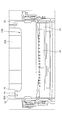
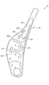
- FIG. 2 is a left side view of the seat back frame 10.
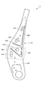
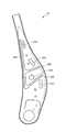
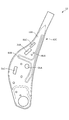
- 3A is an outer side view of the side frame 12
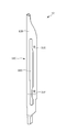
- FIG. 3B is a rear view of the side frame 12
- FIG. 3C is an inner side view of the side frame 12.
- the side frame side portion 12A constituting the side portion of the side frame 12 has an airbag attachment hole 31A, an airbag attachment hole 31B, an airbag attachment hole 31C, and a through hole.
- a plurality of through holes including the hole 31D are formed.
- the airbag attachment hole 31A, the airbag attachment hole 31B, and the airbag attachment hole 31C are through holes used for attaching the airbag unit.
- the airbag unit includes an airbag body, a webbing for guiding the deployment direction of the airbag, a plate for attaching the airbag, and the like.
- the airbag attachment hole 31B and the airbag attachment hole 31C are holes for attaching an airbag bundling
- the airbag attachment hole 31A is a hole through which a bolt extending from a retainer of the airbag body is inserted.
- the through hole 31D is formed at a position facing the lower end of the upper frame side portion 11A, and the side frame 12 and the upper frame 11 are welded in the through hole 31D.
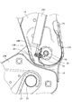
- the side frame side portion 12A constituting the side portion of the side frame 12 is formed with a first reinforcing portion 30A extending along the rear edge 12C.
- the rear edge 12C is a bent portion that hits the boundary between the side frame side portion 12A that forms the side surface of the side frame 12 and the side frame rear portion 12B that forms the rear surface.
- 30 A of 1st reinforcement parts are comprised as a bead part which dented a part of side frame side part 12A inside the sheet
- the first reinforcing portion 30A is provided at least in the wide portion 12D having the widest width in the side frame side portion 12A.
- the first reinforcing portion 30A is provided along the rear edge 12C from a position facing the through hole 31D in the vertical direction to a position facing the airbag mounting hole 31C. That is, the first reinforcing portion 30A is provided at least at a position where the side frame 12 and the upper frame side portion 11A overlap with each other, and thereby the strength of the joint portion between the side frame 12 and the upper frame 11 can be increased.
- the upper end of the first reinforcing portion 30 ⁇ / b> A may be located above the welding position between the side frame 12 and the upper frame 11. As shown in FIG. 2, the first reinforcing portion 30 ⁇ / b> A is provided at a position that overlaps the upper frame 11 and the cushion side frames 22 ⁇ / b> A and 22 ⁇ / b> B when viewed from the side.
- the side frame side portion 12A that constitutes the side portion of the side frame 12 extends forward from the seat between the upper end and the lower end of the first reinforcing portion 30A.
- a second reinforcing portion 30B is formed. Similar to the first reinforcing portion 30A, the second reinforcing portion 30B is configured as a bead portion in which a part of the side frame side portion 12A is recessed into the seat by pressing.
- the second reinforcing portion 30B is formed between the airbag attachment hole 31A and the airbag attachment hole 31B.
- the rear end of the second reinforcing portion 30B is connected to the first reinforcing portion 30A, and both are integrated.
- the front end of the second reinforcing portion 30B is located in front of the seat with respect to the airbag attachment hole 31B, and is located in the rear of the seat with respect to the front edge of the side frame side portion 12A.
- the side frame side portion 12A constituting the side portion of the side frame 12 has a third reinforcing portion extending from the lower end of the first reinforcing portion 30A to the front of the seat. 30C is formed. Similar to the first reinforcing portion 30A, the third reinforcing portion 30C is configured as a bead portion in which a part of the side frame side portion 12A is recessed into the seat by pressing. Here, the third reinforcing portion 30C is formed between the airbag attachment hole 31A and the airbag attachment hole 31C. The rear end of the third reinforcing portion 30C is connected to the first reinforcing portion 30A, and both are integrated. The front end of the third reinforcing portion 30C is located in front of the seat with respect to the airbag attachment hole 31C, and is located in the rear of the seat with respect to the front edge of the side frame side portion 12A.
- the second reinforcing portion 30 ⁇ / b> B is in relation to the torso line T that indicates the axis of the trunk of the three-dimensional mannequin that imitates the occupant seated on the vehicle seat having the seat frame 1 as a skeleton. It extends from the first reinforcing portion 30A at an angle that is substantially orthogonal (ie, substantially perpendicular).
- the third reinforcing portion 30C extends from the first reinforcing portion 30A at an angle (that is, an acute angle) that is not orthogonal to the torso line T.
- the second reinforcing portion 30B and the third reinforcing portion 30C have different angles extending from the first reinforcing portion 30A.
- the first reinforcing portion 30A, the second reinforcing portion 30B, and the third reinforcing portion 30C are provided above the reclining unit 40 in the vertical direction.
- the bottom portions (that is, the bottom portions of the beads) inside the seat of the first reinforcing portion 30A, the second reinforcing portion 30B, and the third reinforcing portion 30C are outside the seat from the end portion of the flange provided in front of the side frame 12.
- the upper end portion of the first reinforcing portion 30A may be narrower than the lower end portion.
- the front end portions of the second reinforcing portion 30B and the third reinforcing portion 30C may be narrower than the rear portion.
- the front end portions of the second reinforcement portion 30B and the third reinforcement portion 30C are the front wall portion 13B of the lower frame 13, the support portion 15A of the pressure receiving member 15, the attachment portion of the reclining unit 40, the headrest attachment portion 17, and the rotating shaft 16. It is good also as positioning ahead.
- the first reinforcing portion 30 ⁇ / b> A, the second reinforcing portion 30 ⁇ / b> B, and the third reinforcing portion 30 ⁇ / b> C may all be located in front of the headrest mounting portion 17.
- a rear reinforcing portion 30 ⁇ / b> D is formed at the center portion of the side frame rear portion 12 ⁇ / b> B of the side frame 12.
- a through hole 31E and a through hole 31F are formed in an upper portion and a lower portion, respectively.
- the rear surface reinforcing portion 30D is configured as a bead portion in which a part of the side frame rear portion 12B is recessed to the inside of the seat by press working.
- the rear reinforcing portion 30D extends from a position facing the upper end of the first reinforcing portion 30A to a position below the lower end of the first reinforcing portion 30A.
- the upper end of the rear surface reinforcing portion 30D is positioned above the through hole 31E formed in the side frame rear portion 12B, and the lower end of the rear surface reinforcing portion 30D is lower than the through hole 31F formed in the side frame rear portion 12B.
- the rear surface reinforcing portion 30D is formed so as to be located at the position.
- the central portion located between the through hole 31E and the through hole 31F in the rear reinforcing portion 30D is a wide portion wider than the upper end and the lower end.
- the lower end of the rear surface reinforcing portion 30D is positioned so as to overlap the lower frame 13 in the vertical direction. As described above, by forming the rear reinforcing portion 30D in the side frame rear portion 12B, the strength can be increased in a wide range of the side frame rear portion 12B.
- the side frame side portion 12A of the side frame 12 with the inverted F-shaped bead portion integrally configured of the first reinforcing portion 30A, the second reinforcing portion 30B, and the third reinforcing portion 30C.
- the strength of a wide range of the side frame side portion 12A can be improved in a balanced manner.
- the strength of the rear edge 12C can be increased by providing the first reinforcing portion 30A along the rear edge 12C.
- the first reinforcing portion 30A is provided at least in the wide portion 12D in the side frame side portion 12A, so that the wide portion is formed even when various through holes for attaching components such as airbags are formed in the wide portion 12D.
- the strength of 12D can be increased.
- the strength around the airbag attachment hole 31A can be increased. Further, by providing the second reinforcing portion 30B between the airbag attachment hole 31A and the airbag attachment hole 31B, the strength around the airbag attachment hole 31A and the airbag attachment hole 31B can be increased. Further, by providing the third reinforcing portion 30C between the airbag attachment hole 31A and the airbag attachment hole 31C, the strength around the airbag attachment hole 31A and the airbag attachment hole 31C can be increased.
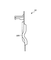
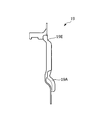
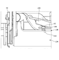
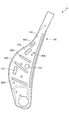
- FIG. 4 is a partially enlarged view of the vicinity of the second connecting bracket 19 from the viewpoint IV in FIG. 5A, 5B, and 5C correspond to an outer side view, a rear view, and an inner side view of the first connection bracket 18, respectively.
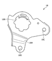
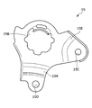
- 6A, 6B, and 6C correspond to an outer side view, a rear view, and an inner side view of the second connection bracket 19, respectively.
- the first connecting bracket 18 is provided with a fragile portion 18A, a shaft through hole 18B, a bolt fastening hole 18C, and a bolt fastening hole 18D.
- the fragile portion 18A is a portion that is provided between the shaft through hole 18B and the bolt fastening hole 18D and is bent to the outside of the seat.
- the weakened portion 18A is easily deformed.
- the shaft through hole 18B is inserted with the rotary shaft 16 and the left reclining unit 40 is attached.
- the left side frame 12 is connected to the first connection bracket 18 via the left reclining unit 40.
- the left cushion side frame 22A is fixed to the bolt fastening hole 18C and the bolt fastening hole 18D by fasteners such as bolts and nuts. For example, at the time of a rear collision of the vehicle, the impact is absorbed by the deformation of the fragile portion 18A of the first connecting bracket 18.
- the second connecting bracket 19 is provided with a fragile portion 19A, a shaft through hole 19B, a bolt fastening hole 19C, a bolt fastening hole 19D, and a fragile portion 19E.
- the fragile portion 19A is a portion that is provided between the shaft through hole 19B and the bolt fastening hole 19D, and is bent to the outside of the seat.
- the weak portion 19 ⁇ / b> A is easily deformed.
- the shaft through-hole 19 ⁇ / b> B is inserted with the rotary shaft 16 and the right reclining unit 40 is attached thereto.
- the right side frame 12 is connected to the second connection bracket 19 via the right reclining unit 40.
- the right cushion side frame 22B is fixed to the bolt fastening hole 19C and the bolt fastening hole 19D by fasteners such as bolts and nuts.
- the fragile portion 19E is a portion that is provided between the shaft through hole 19B and the bolt fastening hole 19C and is bent outward of the seat.
- the weakened portion 19E is easily deformed. For example, at the time of a rear collision of the vehicle, the impact is absorbed by the deformation of the weak part 19A and the weak part 19E of the second connecting bracket 19.
- the weak part 18A of the 1st connection bracket 18 the 1st connection part with the shaft through-hole 18B side and the 2nd connection part by the side of the bolt fastening hole 18D are in the substantially the same position in a sheet
- the fragile portion 19A of the second connection bracket 19 the second connection portion on the bolt fastening hole 19D side is located on the seat inner side in the seat width direction with respect to the first connection portion on the shaft through hole 19B side. ing.
- the 1st connection part and the 2nd connection part are offset in the sheet
- the weak part is not provided between the shaft through-hole 18B and the bolt fastening hole 18C.
- the weak part 19E is provided between the shaft through-hole 19B and the bolt fastening hole 19C.
- a height adjustment unit 41 is provided on the left cushion side frame 22A, and similar components are not provided on the right cushion side frame 22B. Therefore, a larger load is input to the first connecting bracket 18 connected to the left cushion side frame 22A than at the second connecting bracket 19 connected to the right cushion side frame 22B at the time of a rear collision.
- the first connection bracket 18 and the second connection bracket 19 are provided with asymmetric weak portions, and the second connection bracket 19 is more easily deformed than the first connection bracket 18. By doing so, it can adjust so that the deformation
- FIG. 7 is a front view of the seat frame 1 and is a partially enlarged view around the lower frame 13.
- FIG. 8 is a rear view of the seat frame 1 and is a partially enlarged view around the lower frame 13.
- 9 is a cross-sectional view taken along the line IX-IX in FIG. 7, and
- FIG. 10 is a cross-sectional view taken along the line XX in FIG.
- FIG. 11 is an arrow view from the viewpoint XI in FIG. 7 and is a partially enlarged view of the lower frame 13.
- the lower frame 13 includes a rear wall portion 13A formed in a J-shaped cross section constituting the rear portion of the seat, and a front of the seat formed continuously at the front end of the rear wall portion 13A.
- the front wall part 13B which comprises a part is provided.
- the front wall portion 13B of the lower frame 13 is a portion obtained by extending a sheet width portion facing the support portion 15A upward from the front end of the rear wall portion 13A.
- a wire 15B having three clips 50 attached to the lower end is attached to the support portion 15A.
- three attachment parts 51 which are through-holes which fit the clip 50 are formed in the front wall part 13B.
- the attachment portion 51 is separated from the support portion 15A and is provided below the support portion 15A. Further, the attachment portion 51 is provided on the inner side of the left and right ends of the support portion 15A.
- the wire 15B is fixed to the front wall part 13B by fitting the clip 50 attached to the wire 15B to the attachment part 51 of the front wall part 13B.
- an upper reinforcing portion 60A, an upper reinforcing portion 60B, and an upper reinforcing portion 60C that extend in the seat width direction are formed on the upper portion of the attachment portion 51 of each clip 50, respectively. Is done.
- the upper reinforcing portion 60A, the upper reinforcing portion 60B, and the upper reinforcing portion 60C are formed on substantially the same horizontal plane, the upper reinforcing portion 60A on the left side, the upper reinforcing portion 60B on the center, and the right side.
- An upper reinforcing portion 60C is provided.
- the upper reinforcing portion 60A, the upper reinforcing portion 60B, and the upper reinforcing portion 60C are formed as bead portions in which a part of the front wall portion 13B is recessed rearward by pressing.
- the upper reinforcing portion 60A, the upper reinforcing portion 60B, and the upper reinforcing portion 60C are each formed in a shape along the upper edge of the front wall portion 13B. That is, the upper edge of the front wall portion 13B is straight at the center and the left and right ends are arcuate, and the left end of the upper reinforcing portion 60A is arcuate and the other is linear,
- the reinforcing portion 60B is formed in a linear shape
- the right end portion of the upper reinforcing portion 60C is formed in an arc shape
- the other portions are formed in a linear shape.
- the position of the left end portion of the upper reinforcing portion 60 ⁇ / b> A is located on the outer side in the sheet width direction with respect to the opposing attachment portion 51.
- the position of the right end portion of the upper reinforcing portion 60 ⁇ / b> C is located on the outer side in the sheet width direction with respect to the mounting portion 51 facing the upper reinforcing portion 60 ⁇ / b> C.
- the lower reinforcing portion 61A and the lower side spaced apart from each other A reinforcing portion 61B is formed.
- the lower reinforcing portion 61A and the lower reinforcing portion 61B are formed as bead portions in which a boundary portion between the front wall portion 13B and the rear wall portion 13A is recessed rearward by pressing.
- the attachment portion 51 that faces the upper reinforcing portion 60A is provided between the upper reinforcing portion 60A, the lower reinforcing portion 61A, and the lower reinforcing portion 61B in the seat vertical direction.
- the position of the left end portion of the upper reinforcing portion 60A is located on the outer side in the sheet width direction with respect to the lower reinforcing portion 61A.
- the position of the right side edge part of 60 A of upper side reinforcement parts is located in the sheet
- interval of 61 A of lower side reinforcement parts and the lower side reinforcement part 61B is shorter than the length of the width direction of 60 A of upper side reinforcement parts.
- the lower reinforcing portion 61C and the lower side that are spaced apart from each other A reinforcing part 61D is formed.
- the lower reinforcing portion 61C and the lower reinforcing portion 61D are formed as bead portions in which a boundary portion between the front wall portion 13B and the rear wall portion 13A is recessed rearward by pressing.
- the mounting portion 51 facing the upper reinforcing portion 60B is provided between the upper reinforcing portion 60B, the lower reinforcing portion 61C, and the lower reinforcing portion 61D in the seat vertical direction.
- the attaching part 51 which opposes the upper side reinforcement part 60B is provided between 61C of lower side reinforcement parts and 61D of lower side reinforcement parts in the sheet
- the lower reinforcing portion 61E and the lower side that are separated from each other A reinforcing portion 61F is formed.
- the lower reinforcing portion 61E and the lower reinforcing portion 61F are formed as bead portions in which a boundary portion between the front wall portion 13B and the rear wall portion 13A is recessed rearward by pressing.
- the attachment portion 51 that faces the upper reinforcing portion 60C is provided between the upper reinforcing portion 60C, the lower reinforcing portion 61E, and the lower reinforcing portion 61F in the seat vertical direction.
- the position of the left end portion of the upper reinforcing portion 60C is located on the outer side in the sheet width direction with respect to the lower reinforcing portion 61E.
- the position of the right side edge part of 60 C of upper side reinforcement parts is located in the sheet
- interval of the lower side reinforcement part 61E and the lower side reinforcement part 61F is shorter than the length of the width direction of 60 C of upper side reinforcement parts.
- the interval between the upper reinforcing portion 60A and the upper reinforcing portion 60B adjacent on the upper side is shorter than the interval between the lower reinforcing portion 61B and the lower reinforcing portion 61C adjacent on the lower side.
- the interval between the upper reinforcing portion 60B and the upper reinforcing portion 60C adjacent on the upper side is shorter than the interval between the lower reinforcing portion 61D and the lower reinforcing portion 61E adjacent on the lower side.
- the rotation shaft 16 is provided between the rear wall portion 13A and the front wall portion 13B, and the space is not sufficient. Installation work is not easy.
- the attachment portion 51 for attaching the wire 15 ⁇ / b> B of the pressure receiving member 15 is provided on the front wall portion 13 ⁇ / b> B of the lower frame 13, the rotating shaft 16 and the operator's hand do not interfere with each other. The workability of attaching the pressure receiving member 15 can be improved.
- FIG. 9 the configuration of the rear wall portion 13A of the lower frame 13 will be mainly described.
- the upper end of the rear wall portion 13A is located above the upper end of the front wall portion 13B.
- the lower end of the support portion 15A is located above the upper end of the front wall portion 13B and below the upper end of the rear wall portion 13A.
- the front wall portion 13B is provided substantially parallel to the support portion 15A. Since the support portion 15A is substantially parallel to the torso line T, in other words, the front wall portion 13B is provided substantially parallel to the torso line T.
- an upper protruding portion 75 that protrudes upward is provided on each of the upper portions on both outer sides in the seat width direction of the rear wall portion 13 ⁇ / b> A.
- the upward projecting portion 75 is formed in a shape along the side frame 12, and a reinforcing portion 74 is formed at a position facing the rear surface reinforcing portion 30 ⁇ / b> D of the side frame 12.
- the reinforcing portion 74 is formed as a bead portion that is recessed forward of the seat, and has a shape that engages with the rear reinforcing portion 30D. Note that both side portions of the rear wall portion 13A in the seat width direction are joined to the side frame 12 by welding.
- the side frame 12 is provided with the first reinforcing portion 30A, the second reinforcing portion 30B, and the third reinforcing portion 30C on the side frame side portion 12A. 12 rigidity can be improved.
- the extending directions of the first reinforcing portion 30A, the second reinforcing portion 30B, and the third reinforcing portion 30C are different, it is possible to improve the rigidity with respect to input of loads from various directions.
- the mounting work 51 of the pressure receiving member 15 can be improved by providing the mounting portion 51 of the pressure receiving member 15 on the front wall portion 13 ⁇ / b> B of the lower frame 13.
- the rigidity of the periphery of the attachment part 51 can be improved by providing the attachment part 51 of the front wall part 13B with the reinforcement part up and down.
- the present invention is not limited to the above embodiment.
- the modification of the reinforcement part (bead shape) formed in the side frame side part 12A of the side frame 12 is demonstrated.
- 12A to 12D each show an outer side view of the side frame 12 according to a modification.
- the side frame 12 according to the first modification is formed with a reinforcing portion 80A, a reinforcing portion 80B, a reinforcing portion 80C, a reinforcing portion 80D, and a reinforcing portion 80E.
- each of the reinforcing portion 80A, the reinforcing portion 80B, the reinforcing portion 80C, the reinforcing portion 80D, and the reinforcing portion 80E is formed as a bead portion in which the side frame side portion 12A is recessed on the inner side of the sheet by pressing.
- the reinforcing portion 80A is provided along the rear edge 12C of the side frame side portion 12A.
- the reinforcing portion 80B is provided so as to extend in the front-rear direction of the seat between the airbag attachment hole 31A and the airbag attachment hole 31B.
- the reinforcing portion 80C is provided so as to extend in the seat front-rear direction between the airbag attachment hole 31A and the airbag attachment hole 31C.
- the reinforcing portion 80D is provided below the airbag attachment hole 31C so as to extend in the seat front-rear direction.
- the reinforcing portion 80E is provided along the front edge of the side frame side portion 12A in the upper portion of the airbag attachment hole 31B.
- the reinforcing part 80A, the reinforcing part 80B, the reinforcing part 80C, the reinforcing part 80D, and the reinforcing part 80E may be provided as independent bead parts without connecting them to other reinforcing parts.
- the extending directions of the reinforcing portion 80A, the reinforcing portion 80B, the reinforcing portion 80C, the reinforcing portion 80D, and the reinforcing portion 80E may be different.
- the side frame 12 according to the second modification includes a reinforcing portion 81A, a reinforcing portion 81B, and a reinforcing portion 81C.
- each of the reinforcing portion 81A, the reinforcing portion 81B, and the reinforcing portion 81C is formed as a bead portion in which the side frame side portion 12A is recessed on the inner side of the sheet by pressing.
- the reinforcing portion 81A is provided along the rear edge 12C of the side frame side portion 12A. However, the lower end of the reinforcing portion 81A is bent toward the inside of the seat.
- the reinforcing portion 81B is provided so as to extend in the front-rear direction of the seat between the airbag attachment hole 31A and the airbag attachment hole 31B. Further, the rear end of the reinforcing portion 81B is connected to the reinforcing portion 81A.
- the reinforcing portion 81C is provided along the front edge of the side frame side portion 12A in the upper portion of the airbag attachment hole 31B.
- the side frame 12 according to a third modification is formed with a reinforcing part 82A, a reinforcing part 82B, a reinforcing part 82C, and a reinforcing part 82D.
- each of the reinforcing portion 82A, the reinforcing portion 82B, the reinforcing portion 82C, and the reinforcing portion 82D is formed as a bead portion in which the side frame side portion 12A is recessed on the inner side of the sheet by pressing.
- the reinforcing portion 82A is provided along the rear edge 12C of the side frame side portion 12A.
- the reinforcing portion 82A is bent toward the inside of the seat.
- the reinforcing portion 82B is provided so as to extend in the front-rear direction of the seat between the airbag attachment hole 31A and the airbag attachment hole 31B. Further, the rear end of the reinforcing portion 82B is connected to the reinforcing portion 82A.
- the reinforcing portion 82C is provided so as to extend in the front-rear direction of the seat from the bent portion of the reinforcing portion 82A toward the airbag attachment hole 31C. Further, the rear end of the reinforcing portion 82C is connected to the reinforcing portion 82A.
- the reinforcing portion 82D is provided along the front edge of the side frame side portion 12A in the upper portion of the airbag attachment hole 31B.
- the side frame 12 according to a fourth modification is provided with a reinforcing portion 83A, a reinforcing portion 83B, and a reinforcing portion 83C.
- each of the reinforcing portion 83A, the reinforcing portion 83B, and the reinforcing portion 83C is formed as a bead portion in which the side frame side portion 12A is recessed to the inside of the sheet by pressing.
- the reinforcing portion 83A is provided along the rear edge 12C of the side frame side portion 12A.
- the reinforcing portion 83B is formed in an annular shape, and the rear end portion is connected to the reinforcing portion 83A.
- the reinforcing portion 83B is formed between the airbag attachment hole 31A, the airbag attachment hole 31B, and the airbag attachment hole 31C, and encloses the airbag attachment hole 31A.
- the reinforcing portion 83C is provided along the front edge of the side frame side portion 12A in the upper portion of the airbag attachment hole 31B.
Abstract
In order to provide a seat frame in which rigidity of the side frame is strengthened, this seat frame 1 is provided with side frames 12 arranged to the left and right. The seat frame 1 comprises a first reinforcing part 30A which extends in the vertical direction along the back edge 12C of a side frame lateral part 12A positioned to the outside of the side frame 12 in the seat width direction. The seat frame 1 comprises a second reinforcing part 30B which is provided on the side frame lateral part 12A and which extends in the front-back direction of the seat. The second reinforcing part 30B is provided within the range of vertical extension of the first reinforcing part 30A. The seat frame 1 comprises a third reinforcing part 30C which is provided on the side frame lateral part 12A and which extends in the front-back direction in a position separated in the downward direction from the second reinforcing part 30B.
Description
本発明は、サイドフレームを備えるシートフレームに関する。
The present invention relates to a seat frame including a side frame.
自動車等の乗物に搭載されるシートの骨格を成すシートフレームについては軽量化が求められている。例えば下記の特許文献1では、シートフレームの側部を構成するサイドフレームには、薄肉の板状のフレームを用いてフレームを軽量化している。
The weight of the seat frame that forms the skeleton of the seat mounted on a vehicle such as an automobile is required. For example, in Patent Document 1 below, a thin plate-like frame is used as a side frame constituting the side portion of the seat frame to reduce the weight of the frame.
一方、サイドフレームにはエアバッグ、アームレスト等の各種部品を取り付けることがある。こうした場合に、上記の従来技術にも開示されているように、サイドフレームの側面の面積を大きくした板状のフレームが用いられることがある。このようなサイドフレームの側面の面積を大きくした板状のフレームにおいては、剛性の確保が課題となる。
また、サイドフレームには上記の各種部品を取り付けるための孔が形成されることがあり、板状のサイドフレームにおいてこうした孔を多数形成すると、サイドフレームの剛性が低下する虞があった。
以上のように、シートフレームにおいてサイドフレームの剛性を向上させることが課題となっている。 On the other hand, various parts such as an airbag and an armrest may be attached to the side frame. In such a case, as disclosed in the above-described prior art, a plate-shaped frame having a large side surface area may be used. In such a plate-like frame having a large side surface area, securing rigidity is an issue.
In addition, holes for attaching the above-described various parts may be formed in the side frame. If a large number of such holes are formed in the plate-like side frame, there is a possibility that the rigidity of the side frame is lowered.
As described above, it is an issue to improve the rigidity of the side frame in the seat frame.
本発明は、上記の課題に鑑みてなされたものであり、その目的は、サイドフレームの剛性を向上させたシートフレームを提供することにある。
The present invention has been made in view of the above problems, and an object of the present invention is to provide a seat frame with improved side frame rigidity.
上記の課題は、本発明に係るシートフレームによれば、左右に配置されたサイドフレームを備えるシートフレームであって、前記サイドフレームにおいてシート幅方向外側に位置するサイドフレーム側部の後縁に沿って、上下方向に延在する第1の補強部を有することにより解決される。
上記シートフレームによれば、サイドフレーム側部の後縁を補強することにより、サイドフレームの剛性を向上させることができる。 According to the seat frame according to the present invention, the above-described problem is a seat frame including side frames arranged on the left and right sides, and along the rear edge of the side portion of the side frame located on the outer side in the seat width direction in the side frame. This is solved by having the first reinforcing portion extending in the vertical direction.
According to the seat frame, the rigidity of the side frame can be improved by reinforcing the rear edge of the side frame side portion.
また、上記シートフレームにおいて、前記第1の補強部は、前記サイドフレーム側部においてシート前後方向に最も幅が広い幅広部に少なくとも設けられることとしてよい。
こうすることで、サイドフレーム側部における幅広部を補強することにより、サイドフレームの剛性を向上させることができる。 In the seat frame, the first reinforcing portion may be provided at least in a wide portion that is widest in the seat front-rear direction in the side frame side portion.
By doing so, the rigidity of the side frame can be improved by reinforcing the wide part on the side part of the side frame.
また、上記シートフレームにおいて、前記サイドフレーム側部に設けられ、シート前後方向に延在する第2の補強部を有し、前記第2の補強部は、前記第1の補強部が延在する上下の範囲内に設けられることとしてよい。
こうすることで、サイドフレーム側部を上下方向と前後方向に補強することで、サイドフレームの剛性を向上させることができる。 Further, the seat frame includes a second reinforcing portion that is provided on the side portion of the side frame and extends in the front-rear direction of the seat, and the second reinforcing portion extends from the first reinforcing portion. It may be provided within the upper and lower ranges.
By doing so, the rigidity of the side frame can be improved by reinforcing the side frame side portions in the vertical direction and the front-rear direction.
また、上記のシートフレームにおいて、前記第1の補強部と前記第2の補強部は連結していることとしてよい。
こうすることで、第1の補強部と第2の補強部を一体的に形成できる。これにより、補強部の形成を容易とすることができる。 In the seat frame, the first reinforcing portion and the second reinforcing portion may be connected.
By carrying out like this, a 1st reinforcement part and a 2nd reinforcement part can be formed integrally. Thereby, formation of a reinforcement part can be made easy.
また、上記のシートフレームにおいて、前記サイドフレーム側部に設けられ、前記第2の補強部から下方向に離間した位置において、前後方向に延在する第3の補強部を有することとしてよい。
こうすることで、サイドフレーム側部の剛性を広い範囲で向上させることができる。 The seat frame may include a third reinforcing portion that is provided on the side portion of the side frame and extends in the front-rear direction at a position spaced downward from the second reinforcing portion.
By doing so, the rigidity of the side frame side portions can be improved in a wide range.
また、上記のシートフレームにおいて、前記第2の補強部は、前記第1の補強部の上端と下端の間に連結し、前記第3の補強部は、前記第1の補強部の前記下端に連結することとしてよい。
こうすることで、サイドフレーム側部の剛性をバランス良く向上させることができる。 In the seat frame, the second reinforcing portion is connected between an upper end and a lower end of the first reinforcing portion, and the third reinforcing portion is connected to the lower end of the first reinforcing portion. It may be connected.
By doing so, the rigidity of the side frame side portions can be improved in a balanced manner.
また、上記のシートフレームにおいて、前記第2の補強部と前記第3の補強部は、前記第1の補強部に対して延在する角度が異なることとしてよい。
こうすることで、様々な角度からの荷重の入力に対して剛性を向上させることができる。 In the seat frame, the second reinforcing portion and the third reinforcing portion may have different angles extending with respect to the first reinforcing portion.
By doing so, the rigidity can be improved with respect to the input of loads from various angles.
また、上記のシートフレームにおいて、前記第2の補強部は、トルソラインに対して略直交する方向に延在することとしてよい。
こうすることで、荷重の入力が大きい方向に対して剛性を向上させることができる。 In the seat frame, the second reinforcing portion may extend in a direction substantially orthogonal to the torso line.
By doing so, the rigidity can be improved in the direction in which the input of the load is large.
こうすることで、荷重の入力が大きい方向に対して剛性を向上させることができる。 In the seat frame, the second reinforcing portion may extend in a direction substantially orthogonal to the torso line.
By doing so, the rigidity can be improved in the direction in which the input of the load is large.
また、上記のシートフレームにおいて、前記第2の補強部は、前記サイドフレーム側部に形成される複数の貫通孔の間に延在することとしてよい。
こうすることで、貫通孔周辺の剛性を向上させることができる。 In the seat frame, the second reinforcing portion may extend between a plurality of through holes formed in the side frame side portion.
By doing so, the rigidity around the through hole can be improved.
こうすることで、貫通孔周辺の剛性を向上させることができる。 In the seat frame, the second reinforcing portion may extend between a plurality of through holes formed in the side frame side portion.
By doing so, the rigidity around the through hole can be improved.
また、上記のシートフレームにおいて、前記複数の貫通孔は、エアバッグを取り付けるためのエアバッグ取付孔を含み、前記第2の補強部と前記第3の補強部はそれぞれ、前記エアバッグ取付孔を上下で挟む位置に設けられていることとしてよい。
こうすることで、サイドフレームにおいてエアバッグを取り付ける部分の剛性を向上させることができる。 In the seat frame, the plurality of through holes include an airbag attachment hole for attaching an airbag, and the second reinforcement portion and the third reinforcement portion each include the airbag attachment hole. It may be provided at a position sandwiched between the upper and lower sides.
By doing so, the rigidity of the portion where the airbag is attached in the side frame can be improved.
また、上記のシートフレームにおいて、前記第1の補強部は、前記複数の貫通孔のうち少なくとも一つと上下方向において対向する位置にあることとしてよい。
こうすることで、サイドフレームの貫通孔周辺の剛性を向上させることができる。 In the seat frame, the first reinforcing portion may be at a position facing at least one of the plurality of through holes in the vertical direction.
By doing so, the rigidity around the through hole of the side frame can be improved.
こうすることで、サイドフレームの貫通孔周辺の剛性を向上させることができる。 In the seat frame, the first reinforcing portion may be at a position facing at least one of the plurality of through holes in the vertical direction.
By doing so, the rigidity around the through hole of the side frame can be improved.
また、上記のシートフレームにおいて、前記サイドフレームの上部を連結する上部フレームを備え、前記サイドフレーム側部は、前記上部フレームにおいてシート幅方向外側に位置する上部フレーム側部と接合し、前記第1の補強部は、前記サイドフレーム側部と前記上部フレーム側部が重なる位置に少なくとも設けられることとしてよい。
こうすることで、サイドフレームと上部フレームとの接合部分の剛性を向上させることができる。 The seat frame further includes an upper frame that connects the upper portions of the side frames, and the side frame side portion is joined to an upper frame side portion that is located on the outer side in the seat width direction of the upper frame, and The reinforcing portion may be provided at least at a position where the side frame side portion and the upper frame side portion overlap each other.
By doing so, the rigidity of the joint portion between the side frame and the upper frame can be improved.
本発明によれば、サイドフレーム側部の後縁を補強することにより、サイドフレームの剛性を向上させることができる。
According to the present invention, the rigidity of the side frame can be improved by reinforcing the rear edge of the side frame side portion.
本発明の一側面によれば、サイドフレーム側部における幅広部を補強することにより、サイドフレームの剛性を向上させることができる。
According to one aspect of the present invention, the rigidity of the side frame can be improved by reinforcing the wide portion at the side portion of the side frame.
本発明の一側面によれば、サイドフレーム側部を上下方向と前後方向に補強することで、サイドフレームの剛性を向上させることができる。
According to one aspect of the present invention, the rigidity of the side frame can be improved by reinforcing the side frame side portions in the vertical direction and the front-rear direction.
本発明の一側面によれば、補強部の形成を容易とすることができる。
According to one aspect of the present invention, the reinforcing portion can be easily formed.
本発明の一側面によれば、サイドフレーム側部の剛性を広い範囲で向上させることができる。
According to one aspect of the present invention, the rigidity of the side frame side portion can be improved in a wide range.
本発明の一側面によれば、サイドフレーム側部の剛性をバランス良く向上させることができる。
According to one aspect of the present invention, the rigidity of the side frame side portions can be improved in a well-balanced manner.
本発明の一側面によれば、様々な角度からの荷重の入力に対して剛性を向上させることができる。
According to one aspect of the present invention, rigidity can be improved with respect to input of loads from various angles.
本発明の一側面によれば、荷重の入力が大きい方向に対して剛性を向上させることができる。
According to one aspect of the present invention, the rigidity can be improved in the direction in which the input of the load is large.
本発明の一側面によれば、貫通孔周辺の剛性を向上させることができる。
According to one aspect of the present invention, the rigidity around the through hole can be improved.
本発明の一側面によれば、サイドフレームにおいてエアバッグを取り付ける部分の剛性を向上させることができる。
According to one aspect of the present invention, it is possible to improve the rigidity of the portion where the airbag is attached in the side frame.
本発明の一側面によれば、サイドフレームの貫通孔周辺の剛性を向上させることができる。
According to one aspect of the present invention, the rigidity around the through hole of the side frame can be improved.
本発明の一側面によれば、サイドフレームと上部フレームとの接合部分の剛性を向上させることができる。
According to one aspect of the present invention, the rigidity of the joint portion between the side frame and the upper frame can be improved.
以下、図1乃至図12Dに基づき、本発明の実施の形態(以下、本実施形態)に係るシートフレーム1について説明する。シートフレーム1は、車両に搭載される車両用シートの骨格をなすものである。
なお、以下に説明する実施形態は、本発明の理解を容易にするための一例に過ぎず、本発明を限定するものではない。すなわち、以下に説明する部材の形状、寸法、配置等については、本発明の趣旨を逸脱することなく、変更、改良され得るとともに、本発明にはその等価物が含まれることは勿論である。 Hereinafter, aseat frame 1 according to an embodiment of the present invention (hereinafter, this embodiment) will be described with reference to FIGS. 1 to 12D. The seat frame 1 forms a skeleton of a vehicle seat mounted on a vehicle.
The embodiment described below is merely an example for facilitating the understanding of the present invention, and does not limit the present invention. That is, the shape, dimensions, arrangement, and the like of the members described below can be changed and improved without departing from the spirit of the present invention, and the present invention naturally includes equivalents thereof.
なお、以下に説明する実施形態は、本発明の理解を容易にするための一例に過ぎず、本発明を限定するものではない。すなわち、以下に説明する部材の形状、寸法、配置等については、本発明の趣旨を逸脱することなく、変更、改良され得るとともに、本発明にはその等価物が含まれることは勿論である。 Hereinafter, a
The embodiment described below is merely an example for facilitating the understanding of the present invention, and does not limit the present invention. That is, the shape, dimensions, arrangement, and the like of the members described below can be changed and improved without departing from the spirit of the present invention, and the present invention naturally includes equivalents thereof.
以下の説明中、「前後方向」とは、車両用シートの着座者から見たときの前後方向を意味し、車両の走行方向と一致する方向である。
「シート幅方向」とは、車両用シートの横幅方向を意味し、車両用シートの着座者から見たときの左右方向と一致する。
また、「上下方向」とは、車両用シートの高さ方向を意味し、車両用シートを正面から見たときの上下方向と一致している。 In the following description, the “front-rear direction” means the front-rear direction when viewed from the seated person of the vehicle seat and is the direction that coincides with the traveling direction of the vehicle.
The “seat width direction” means the lateral width direction of the vehicle seat and coincides with the left-right direction when viewed from the seated person of the vehicle seat.
The “vertical direction” means the height direction of the vehicle seat, and coincides with the vertical direction when the vehicle seat is viewed from the front.
[1.シートフレーム1の概要]
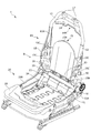
まず、図1を参照しながら、シートフレーム1の構成の概要について説明する。図1に示されるように、シートフレーム1は、主にシートバックフレーム10とシートクッションフレーム20とにより構成される。シートバックフレーム10は、シートフレーム1における背もたれ部分の骨格をなし、シートクッションフレーム20は、シートフレーム1における着座部分の骨格をなす。 [1. Overview of seat frame 1]
First, the outline of the configuration of theseat frame 1 will be described with reference to FIG. As shown in FIG. 1, the seat frame 1 mainly includes a seat back frame 10 and a seat cushion frame 20. The seat back frame 10 forms a skeleton of a backrest portion in the seat frame 1, and the seat cushion frame 20 forms a skeleton of a seating portion in the seat frame 1.
まず、図1を参照しながら、シートフレーム1の構成の概要について説明する。図1に示されるように、シートフレーム1は、主にシートバックフレーム10とシートクッションフレーム20とにより構成される。シートバックフレーム10は、シートフレーム1における背もたれ部分の骨格をなし、シートクッションフレーム20は、シートフレーム1における着座部分の骨格をなす。 [1. Overview of seat frame 1]
First, the outline of the configuration of the
図1に示されるように、シートバックフレーム10は、逆さU字形の上部フレーム11と、シート幅方向左右の端部をなす一対のサイドフレーム12と、一対のサイドフレーム12の下端部を連結する下部フレーム13と、を備える。
As shown in FIG. 1, the seat back frame 10 connects an inverted U-shaped upper frame 11, a pair of side frames 12 that form left and right ends in the seat width direction, and a lower end of the pair of side frames 12. A lower frame 13.
上部フレーム11は、上部フレーム11の両側下部をなす上部フレーム側部11Aにおいて、サイドフレーム12に溶接されている。
また、上部フレーム11の上端には、ヘッドレスト取付部17が溶接により取り付けられる。ヘッドレスト取付部17は、図示しないヘッドレストから垂下する2つのヘッドレストステーが挿通される管状体である。
また、上部フレーム11の上部フレーム側部11Aより上方における両端部にクロスメンバ14が架設されている。クロスメンバ14の中央部分には、左右よりもシート上方に凹んだ凹部14Aが形成される。凹部14Aは、左右のヘッドレスト取付部17の間に設けられることとしてよい。
このようにシートフレーム1では、クロスメンバ14に凹部14Aを形成することにより、シートフレーム1の軽量化を図っている。
なお、凹部14Aは、クロスメンバ14の下端に形成しているが、上端に形成してもよい。また、凹部14Aはクロスメンバ14の上端と下端の両方に形成してもよい。 Theupper frame 11 is welded to the side frame 12 at an upper frame side portion 11 </ b> A that forms lower portions on both sides of the upper frame 11.
Aheadrest attachment portion 17 is attached to the upper end of the upper frame 11 by welding. The headrest mounting portion 17 is a tubular body through which two headrest stays hanging from a headrest (not shown) are inserted.
Further,cross members 14 are installed at both ends of the upper frame 11 above the upper frame side portion 11A. In the central portion of the cross member 14, a recess 14A is formed that is recessed above the seat from the left and right. The recess 14 </ b> A may be provided between the left and right headrest mounting portions 17.
Thus, in theseat frame 1, the weight of the seat frame 1 is reduced by forming the recess 14 </ b> A in the cross member 14.
Therecess 14A is formed at the lower end of the cross member 14, but may be formed at the upper end. The recess 14A may be formed at both the upper end and the lower end of the cross member 14.
また、上部フレーム11の上端には、ヘッドレスト取付部17が溶接により取り付けられる。ヘッドレスト取付部17は、図示しないヘッドレストから垂下する2つのヘッドレストステーが挿通される管状体である。
また、上部フレーム11の上部フレーム側部11Aより上方における両端部にクロスメンバ14が架設されている。クロスメンバ14の中央部分には、左右よりもシート上方に凹んだ凹部14Aが形成される。凹部14Aは、左右のヘッドレスト取付部17の間に設けられることとしてよい。
このようにシートフレーム1では、クロスメンバ14に凹部14Aを形成することにより、シートフレーム1の軽量化を図っている。
なお、凹部14Aは、クロスメンバ14の下端に形成しているが、上端に形成してもよい。また、凹部14Aはクロスメンバ14の上端と下端の両方に形成してもよい。 The
A
Further,
Thus, in the
The
図1に示されるように、左右のサイドフレーム12の下端部の間にはリクライニングユニット40の回転軸16が、左右のサイドフレーム12を貫通した状態で取り付けられる。
なお、リクライニング操作部を操作することによりリクライニングユニット40を動作させることで、シートクッションフレーム20に対するシートバックフレーム10の角度を調整可能となっている。 As shown in FIG. 1, the rotatingshaft 16 of the reclining unit 40 is attached between the lower ends of the left and right side frames 12 so as to penetrate the left and right side frames 12.
The angle of the seat backframe 10 relative to the seat cushion frame 20 can be adjusted by operating the reclining unit 40 by operating the reclining operation unit.
なお、リクライニング操作部を操作することによりリクライニングユニット40を動作させることで、シートクッションフレーム20に対するシートバックフレーム10の角度を調整可能となっている。 As shown in FIG. 1, the rotating
The angle of the seat back
シートバックフレーム10の中央部には、乗員からの荷重を受け止める受圧部材15が架設されている。ここで、受圧部材15は、支持部15A、ワイヤ15B、ワイヤ15Cを備える。
支持部15Aは、乗員の背部を支持し、例えば板バネやSバネ等の弾性部材により構成される。なお、支持部15Aにおいてシート前方の面を支持面と称する。
ワイヤ15Bは、支持部15Aと、下部フレーム13の前壁部13Bにそれぞれ係止される。具体的には、ワイヤ15Bは、下部フレーム13の前壁部13Bに対しては、前壁部13Bに形成された貫通孔に嵌合するクリップ50を用いて係止される。
ワイヤ15Cは、支持部15Aの側端部と、サイドフレーム12にそれぞれ係止される。
このように、支持部15Aは、ワイヤ15Bとワイヤ15Cによりシートバックフレーム10に固定される。 Apressure receiving member 15 that receives a load from an occupant is provided at the center of the seat back frame 10. Here, the pressure receiving member 15 includes a support portion 15A, a wire 15B, and a wire 15C.
Thesupport portion 15A supports the back of the occupant and is configured by an elastic member such as a leaf spring or an S spring. Note that a surface in front of the seat in the support portion 15A is referred to as a support surface.
Thewires 15B are locked to the support portion 15A and the front wall portion 13B of the lower frame 13, respectively. Specifically, the wire 15B is locked to the front wall portion 13B of the lower frame 13 using a clip 50 that fits into a through hole formed in the front wall portion 13B.
Thewires 15C are locked to the side end portions of the support portion 15A and the side frames 12, respectively.
As described above, thesupport portion 15A is fixed to the seat back frame 10 by the wires 15B and 15C.
支持部15Aは、乗員の背部を支持し、例えば板バネやSバネ等の弾性部材により構成される。なお、支持部15Aにおいてシート前方の面を支持面と称する。
ワイヤ15Bは、支持部15Aと、下部フレーム13の前壁部13Bにそれぞれ係止される。具体的には、ワイヤ15Bは、下部フレーム13の前壁部13Bに対しては、前壁部13Bに形成された貫通孔に嵌合するクリップ50を用いて係止される。
ワイヤ15Cは、支持部15Aの側端部と、サイドフレーム12にそれぞれ係止される。
このように、支持部15Aは、ワイヤ15Bとワイヤ15Cによりシートバックフレーム10に固定される。 A
The
The
The
As described above, the
次に、シートクッションフレーム20について説明する。図1に示されるように、シートクッションフレーム20は、上方から見たときに方形枠状の外形形状をなす。そして、シートクッションフレーム20は、シート幅方向左右の端部にそれぞれ構成するクッションサイドフレーム22A,22Bと、シートクッションフレーム20の前端部を構成するパンフレーム21と、左右のクッションサイドフレーム22A,22Bを連結する連結パイプ23とを主たる構成要素とする。例えば、連結パイプ23は、丸パイプ等の中空部材であり、乗員の臀部を支持する受圧部材24の後端が取り付けられる。
Next, the seat cushion frame 20 will be described. As shown in FIG. 1, the seat cushion frame 20 has a rectangular frame-like outer shape when viewed from above. The seat cushion frame 20 includes cushion side frames 22A and 22B that are respectively configured at left and right ends in the seat width direction, a pan frame 21 that is configured as a front end of the seat cushion frame 20, and left and right cushion side frames 22A and 22B. The connecting pipe 23 connecting the two is a main component. For example, the connecting pipe 23 is a hollow member such as a round pipe, and the rear end of the pressure receiving member 24 that supports the occupant's buttocks is attached.
図1に示されるように、左のクッションサイドフレーム22Aの後端部の上部には、第1連結ブラケット18が取り付けられている。そして、第1連結ブラケット18には、リクライニングユニット40を介して左のサイドフレーム12が連結されている。
また、図4に示されるように、右のクッションサイドフレーム22Bの後端部の上部には、第2連結ブラケット19が取り付けられている。そして、第2連結ブラケット19には、リクライニングユニット40を介して右のサイドフレーム12が連結されている。
なお、第1連結ブラケット18と第2連結ブラケット19の構成の詳細については後述する。 As shown in FIG. 1, afirst connection bracket 18 is attached to the upper part of the rear end portion of the left cushion side frame 22 </ b> A. The left side frame 12 is connected to the first connection bracket 18 via a reclining unit 40.
As shown in FIG. 4, thesecond connection bracket 19 is attached to the upper portion of the rear end portion of the right cushion side frame 22 </ b> B. The right side frame 12 is connected to the second connection bracket 19 via a reclining unit 40.
In addition, the detail of a structure of the1st connection bracket 18 and the 2nd connection bracket 19 is mentioned later.
また、図4に示されるように、右のクッションサイドフレーム22Bの後端部の上部には、第2連結ブラケット19が取り付けられている。そして、第2連結ブラケット19には、リクライニングユニット40を介して右のサイドフレーム12が連結されている。
なお、第1連結ブラケット18と第2連結ブラケット19の構成の詳細については後述する。 As shown in FIG. 1, a
As shown in FIG. 4, the
In addition, the detail of a structure of the
[2.サイドフレーム12の構成]
次に、図2,図3A,図3B及び図3Cを参照しながら、サイドフレーム12の構成について説明する。
図2は、シートバックフレーム10の左側面図である。図3Aはサイドフレーム12の外側面図、図3Bはサイドフレーム12の後面図、図3Cはサイドフレーム12の内側面図である。 [2. Configuration of side frame 12]
Next, the configuration of theside frame 12 will be described with reference to FIGS. 2, 3A, 3B, and 3C.
FIG. 2 is a left side view of the seat backframe 10. 3A is an outer side view of the side frame 12, FIG. 3B is a rear view of the side frame 12, and FIG. 3C is an inner side view of the side frame 12.
次に、図2,図3A,図3B及び図3Cを参照しながら、サイドフレーム12の構成について説明する。
図2は、シートバックフレーム10の左側面図である。図3Aはサイドフレーム12の外側面図、図3Bはサイドフレーム12の後面図、図3Cはサイドフレーム12の内側面図である。 [2. Configuration of side frame 12]
Next, the configuration of the
FIG. 2 is a left side view of the seat back
図2、図3A及び図3Cに示されるように、サイドフレーム12の側部を構成するサイドフレーム側部12Aには、エアバッグ取付孔31A、エアバッグ取付孔31B、エアバッグ取付孔31C、貫通孔31Dを含む複数の貫通孔が形成される。
エアバッグ取付孔31A、エアバッグ取付孔31B及びエアバッグ取付孔31Cは、エアバッグユニットの取り付けに用いられる貫通孔である。ここで、エアバッグユニットには、エアバッグ本体、エアバッグの展開方向を案内する力布、エアバッグ取付用のプレート等が含まれる。例えば、エアバッグ取付孔31B及びエアバッグ取付孔31Cは、エアバッグの力布を取り付ける孔であり、エアバッグ取付孔31Aはエアバッグ本体のリテーナから延出するボルトが挿通される孔である。
貫通孔31Dは、上部フレーム側部11Aの下端と対向する位置に形成されており、貫通孔31Dにおいてサイドフレーム12と上部フレーム11が溶接される。 As shown in FIGS. 2, 3A and 3C, the sideframe side portion 12A constituting the side portion of the side frame 12 has an airbag attachment hole 31A, an airbag attachment hole 31B, an airbag attachment hole 31C, and a through hole. A plurality of through holes including the hole 31D are formed.
Theairbag attachment hole 31A, the airbag attachment hole 31B, and the airbag attachment hole 31C are through holes used for attaching the airbag unit. Here, the airbag unit includes an airbag body, a webbing for guiding the deployment direction of the airbag, a plate for attaching the airbag, and the like. For example, the airbag attachment hole 31B and the airbag attachment hole 31C are holes for attaching an airbag bundling, and the airbag attachment hole 31A is a hole through which a bolt extending from a retainer of the airbag body is inserted.
The throughhole 31D is formed at a position facing the lower end of the upper frame side portion 11A, and the side frame 12 and the upper frame 11 are welded in the through hole 31D.
エアバッグ取付孔31A、エアバッグ取付孔31B及びエアバッグ取付孔31Cは、エアバッグユニットの取り付けに用いられる貫通孔である。ここで、エアバッグユニットには、エアバッグ本体、エアバッグの展開方向を案内する力布、エアバッグ取付用のプレート等が含まれる。例えば、エアバッグ取付孔31B及びエアバッグ取付孔31Cは、エアバッグの力布を取り付ける孔であり、エアバッグ取付孔31Aはエアバッグ本体のリテーナから延出するボルトが挿通される孔である。
貫通孔31Dは、上部フレーム側部11Aの下端と対向する位置に形成されており、貫通孔31Dにおいてサイドフレーム12と上部フレーム11が溶接される。 As shown in FIGS. 2, 3A and 3C, the side
The
The through
図2、図3A及び図3Cに示されるように、サイドフレーム12の側部を構成するサイドフレーム側部12Aには、その後縁12Cに沿って延在する第1補強部30Aが形成される。なお、後縁12Cは、サイドフレーム12の側面をなすサイドフレーム側部12Aと、後面をなすサイドフレーム後部12Bとの境界に当たる屈曲部である。
第1補強部30Aは、例えばサイドフレーム側部12Aの一部をプレス加工によりシート内側に凹ませたビード部として構成される。
ここで、第1補強部30Aは、サイドフレーム側部12Aにおいて最も幅が広い幅広部12Dに少なくとも設けられる。
本実施形態では、第1補強部30Aは、後縁12Cに沿って、上下方向において貫通孔31Dと対向する位置から、エアバッグ取付孔31Cと対向する位置に渡って設けられている。
すなわち、第1補強部30Aは、サイドフレーム12と上部フレーム側部11Aとが重なる位置に少なくとも設けられており、これによりサイドフレーム12と上部フレーム11との接合部分の強度を高めることができる。
なお、第1補強部30Aの上端は、サイドフレーム12と上部フレーム11との溶接位置よりも上方に位置することとしてよい。
また、図2に示されるように、第1補強部30Aは、側面視において上部フレーム11、クッションサイドフレーム22A,22Bと上下において重なる位置に設けられている。 As shown in FIGS. 2, 3A and 3C, the sideframe side portion 12A constituting the side portion of the side frame 12 is formed with a first reinforcing portion 30A extending along the rear edge 12C. The rear edge 12C is a bent portion that hits the boundary between the side frame side portion 12A that forms the side surface of the side frame 12 and the side frame rear portion 12B that forms the rear surface.
30 A of 1st reinforcement parts are comprised as a bead part which dented a part of sideframe side part 12A inside the sheet | seat by press work, for example.
Here, the first reinforcingportion 30A is provided at least in the wide portion 12D having the widest width in the side frame side portion 12A.
In the present embodiment, the first reinforcingportion 30A is provided along the rear edge 12C from a position facing the through hole 31D in the vertical direction to a position facing the airbag mounting hole 31C.
That is, the first reinforcingportion 30A is provided at least at a position where the side frame 12 and the upper frame side portion 11A overlap with each other, and thereby the strength of the joint portion between the side frame 12 and the upper frame 11 can be increased.
The upper end of the first reinforcing portion 30 </ b> A may be located above the welding position between theside frame 12 and the upper frame 11.
As shown in FIG. 2, the first reinforcing portion 30 </ b> A is provided at a position that overlaps theupper frame 11 and the cushion side frames 22 </ b> A and 22 </ b> B when viewed from the side.
第1補強部30Aは、例えばサイドフレーム側部12Aの一部をプレス加工によりシート内側に凹ませたビード部として構成される。
ここで、第1補強部30Aは、サイドフレーム側部12Aにおいて最も幅が広い幅広部12Dに少なくとも設けられる。
本実施形態では、第1補強部30Aは、後縁12Cに沿って、上下方向において貫通孔31Dと対向する位置から、エアバッグ取付孔31Cと対向する位置に渡って設けられている。
すなわち、第1補強部30Aは、サイドフレーム12と上部フレーム側部11Aとが重なる位置に少なくとも設けられており、これによりサイドフレーム12と上部フレーム11との接合部分の強度を高めることができる。
なお、第1補強部30Aの上端は、サイドフレーム12と上部フレーム11との溶接位置よりも上方に位置することとしてよい。
また、図2に示されるように、第1補強部30Aは、側面視において上部フレーム11、クッションサイドフレーム22A,22Bと上下において重なる位置に設けられている。 As shown in FIGS. 2, 3A and 3C, the side
30 A of 1st reinforcement parts are comprised as a bead part which dented a part of side
Here, the first reinforcing
In the present embodiment, the first reinforcing
That is, the first reinforcing
The upper end of the first reinforcing portion 30 </ b> A may be located above the welding position between the
As shown in FIG. 2, the first reinforcing portion 30 </ b> A is provided at a position that overlaps the
図2、図3A及び図3Cに示されるように、サイドフレーム12の側部を構成するサイドフレーム側部12Aには、第1補強部30Aの上端と下端の間から、シート前方に延在する第2補強部30Bが形成される。
第2補強部30Bは、第1補強部30Aと同様に、サイドフレーム側部12Aの一部をプレス加工によりシート内側に凹ませたビード部として構成される。
ここで、第2補強部30Bは、エアバッグ取付孔31Aとエアバッグ取付孔31Bとの間に形成される。
なお、第2補強部30Bの後端は、第1補強部30Aに接続し、両者が一体となっている。そして、第2補強部30Bの前端は、エアバッグ取付孔31Bよりもシート前方に位置するとともに、サイドフレーム側部12Aの前縁よりはシート後方に位置する。 As shown in FIGS. 2, 3A, and 3C, the sideframe side portion 12A that constitutes the side portion of the side frame 12 extends forward from the seat between the upper end and the lower end of the first reinforcing portion 30A. A second reinforcing portion 30B is formed.
Similar to the first reinforcingportion 30A, the second reinforcing portion 30B is configured as a bead portion in which a part of the side frame side portion 12A is recessed into the seat by pressing.
Here, the second reinforcingportion 30B is formed between the airbag attachment hole 31A and the airbag attachment hole 31B.
The rear end of the second reinforcingportion 30B is connected to the first reinforcing portion 30A, and both are integrated. The front end of the second reinforcing portion 30B is located in front of the seat with respect to the airbag attachment hole 31B, and is located in the rear of the seat with respect to the front edge of the side frame side portion 12A.
第2補強部30Bは、第1補強部30Aと同様に、サイドフレーム側部12Aの一部をプレス加工によりシート内側に凹ませたビード部として構成される。
ここで、第2補強部30Bは、エアバッグ取付孔31Aとエアバッグ取付孔31Bとの間に形成される。
なお、第2補強部30Bの後端は、第1補強部30Aに接続し、両者が一体となっている。そして、第2補強部30Bの前端は、エアバッグ取付孔31Bよりもシート前方に位置するとともに、サイドフレーム側部12Aの前縁よりはシート後方に位置する。 As shown in FIGS. 2, 3A, and 3C, the side
Similar to the first reinforcing
Here, the second reinforcing
The rear end of the second reinforcing
図2、図3A及び図3Cに示されるように、サイドフレーム12の側部を構成するサイドフレーム側部12Aには、第1補強部30Aの下端から、シート前方に延在する第3補強部30Cが形成される。
第3補強部30Cは、第1補強部30Aと同様に、サイドフレーム側部12Aの一部をプレス加工によりシート内側に凹ませたビード部として構成される。
ここで、第3補強部30Cは、エアバッグ取付孔31Aとエアバッグ取付孔31Cとの間に形成される。
なお、第3補強部30Cの後端は、第1補強部30Aに接続し、両者が一体となっている。そして、第3補強部30Cの前端は、エアバッグ取付孔31Cよりもシート前方に位置するとともに、サイドフレーム側部12Aの前縁よりはシート後方に位置する。 As shown in FIGS. 2, 3A and 3C, the sideframe side portion 12A constituting the side portion of the side frame 12 has a third reinforcing portion extending from the lower end of the first reinforcing portion 30A to the front of the seat. 30C is formed.
Similar to the first reinforcingportion 30A, the third reinforcing portion 30C is configured as a bead portion in which a part of the side frame side portion 12A is recessed into the seat by pressing.
Here, the third reinforcingportion 30C is formed between the airbag attachment hole 31A and the airbag attachment hole 31C.
The rear end of the third reinforcingportion 30C is connected to the first reinforcing portion 30A, and both are integrated. The front end of the third reinforcing portion 30C is located in front of the seat with respect to the airbag attachment hole 31C, and is located in the rear of the seat with respect to the front edge of the side frame side portion 12A.
第3補強部30Cは、第1補強部30Aと同様に、サイドフレーム側部12Aの一部をプレス加工によりシート内側に凹ませたビード部として構成される。
ここで、第3補強部30Cは、エアバッグ取付孔31Aとエアバッグ取付孔31Cとの間に形成される。
なお、第3補強部30Cの後端は、第1補強部30Aに接続し、両者が一体となっている。そして、第3補強部30Cの前端は、エアバッグ取付孔31Cよりもシート前方に位置するとともに、サイドフレーム側部12Aの前縁よりはシート後方に位置する。 As shown in FIGS. 2, 3A and 3C, the side
Similar to the first reinforcing
Here, the third reinforcing
The rear end of the third reinforcing
また、図2に示されるように、シートフレーム1を骨格とする車両用シートに着座する乗員を模した3次元マネキンの胴部の軸線を示すトルソラインTに対して、第2補強部30Bは略直交する角度(すなわち略直角)で、第1補強部30Aから延在している。
一方で、第3補強部30Cは、トルソラインTに対して直交しない角度(すなわち鋭角)で、第1補強部30Aから延在している。
すなわち、第2補強部30Bと第3補強部30Cとは、第1補強部30Aから延在する角度がそれぞれ異なっている。
このように、第1補強部30A、第2補強部30B、第3補強部30Cの延在角度をそれぞれ異ならせることで、様々な方向からの荷重入力に対して剛性を強化することができる。
また、第1補強部30A、第2補強部30B、第3補強部30Cはそれぞれ上下方向においてリクライニングユニット40よりも上側に設けられる。 In addition, as shown in FIG. 2, the second reinforcing portion 30 </ b> B is in relation to the torso line T that indicates the axis of the trunk of the three-dimensional mannequin that imitates the occupant seated on the vehicle seat having theseat frame 1 as a skeleton. It extends from the first reinforcing portion 30A at an angle that is substantially orthogonal (ie, substantially perpendicular).
On the other hand, the third reinforcingportion 30C extends from the first reinforcing portion 30A at an angle (that is, an acute angle) that is not orthogonal to the torso line T.
That is, the second reinforcingportion 30B and the third reinforcing portion 30C have different angles extending from the first reinforcing portion 30A.
As described above, by making the extending angles of the first reinforcingportion 30A, the second reinforcing portion 30B, and the third reinforcing portion 30C different from each other, it is possible to enhance the rigidity against load input from various directions.
In addition, the first reinforcingportion 30A, the second reinforcing portion 30B, and the third reinforcing portion 30C are provided above the reclining unit 40 in the vertical direction.
一方で、第3補強部30Cは、トルソラインTに対して直交しない角度(すなわち鋭角)で、第1補強部30Aから延在している。
すなわち、第2補強部30Bと第3補強部30Cとは、第1補強部30Aから延在する角度がそれぞれ異なっている。
このように、第1補強部30A、第2補強部30B、第3補強部30Cの延在角度をそれぞれ異ならせることで、様々な方向からの荷重入力に対して剛性を強化することができる。
また、第1補強部30A、第2補強部30B、第3補強部30Cはそれぞれ上下方向においてリクライニングユニット40よりも上側に設けられる。 In addition, as shown in FIG. 2, the second reinforcing portion 30 </ b> B is in relation to the torso line T that indicates the axis of the trunk of the three-dimensional mannequin that imitates the occupant seated on the vehicle seat having the
On the other hand, the third reinforcing
That is, the second reinforcing
As described above, by making the extending angles of the first reinforcing
In addition, the first reinforcing
また、第1補強部30A、第2補強部30B、第3補強部30Cのシート内側の底部(すなわち、ビードの底部)は、サイドフレーム12の前方に設けられたフランジの端部よりもシート外側に位置する。
また、第1補強部30Aの上端部は、下端部に比べて幅を狭くすることとしてよい。
また、第2補強部30B及び第3補強部30Cの前端部は、後方部に比べて幅を狭くすることとしてよい。
また、第2補強部30B及び第3補強部30Cの前端部は、下部フレーム13の前壁部13B、受圧部材15の支持部15A、リクライニングユニット40の取付部、ヘッドレスト取付部17、回転軸16よりも前方に位置することとしてよい。
また、第1補強部30A、第2補強部30B、第3補強部30Cはいずれもヘッドレスト取付部17よりも前方に位置することとしてよい。 Further, the bottom portions (that is, the bottom portions of the beads) inside the seat of the first reinforcingportion 30A, the second reinforcing portion 30B, and the third reinforcing portion 30C are outside the seat from the end portion of the flange provided in front of the side frame 12. Located in.
Further, the upper end portion of the first reinforcingportion 30A may be narrower than the lower end portion.
In addition, the front end portions of the second reinforcingportion 30B and the third reinforcing portion 30C may be narrower than the rear portion.
Further, the front end portions of thesecond reinforcement portion 30B and the third reinforcement portion 30C are the front wall portion 13B of the lower frame 13, the support portion 15A of the pressure receiving member 15, the attachment portion of the reclining unit 40, the headrest attachment portion 17, and the rotating shaft 16. It is good also as positioning ahead.
Further, the first reinforcing portion 30 </ b> A, the second reinforcing portion 30 </ b> B, and the third reinforcing portion 30 </ b> C may all be located in front of theheadrest mounting portion 17.
また、第1補強部30Aの上端部は、下端部に比べて幅を狭くすることとしてよい。
また、第2補強部30B及び第3補強部30Cの前端部は、後方部に比べて幅を狭くすることとしてよい。
また、第2補強部30B及び第3補強部30Cの前端部は、下部フレーム13の前壁部13B、受圧部材15の支持部15A、リクライニングユニット40の取付部、ヘッドレスト取付部17、回転軸16よりも前方に位置することとしてよい。
また、第1補強部30A、第2補強部30B、第3補強部30Cはいずれもヘッドレスト取付部17よりも前方に位置することとしてよい。 Further, the bottom portions (that is, the bottom portions of the beads) inside the seat of the first reinforcing
Further, the upper end portion of the first reinforcing
In addition, the front end portions of the second reinforcing
Further, the front end portions of the
Further, the first reinforcing portion 30 </ b> A, the second reinforcing portion 30 </ b> B, and the third reinforcing portion 30 </ b> C may all be located in front of the
図3Bに示されるように、サイドフレーム12のサイドフレーム後部12Bの中央部分には、後面補強部30Dが形成される。サイドフレーム後部12Bには、上部と下部にそれぞれ貫通孔31Eと貫通孔31Fが形成される。
後面補強部30Dは、サイドフレーム後部12Bの一部をプレス加工によりシート内側に凹ませたビード部として構成される。後面補強部30Dは、第1補強部30Aの上端に対向する位置から、第1補強部30Aの下端より下方の位置まで延在している。
また、後面補強部30Dの上端は、サイドフレーム後部12Bに形成された貫通孔31Eよりも上方に位置し、後面補強部30Dの下端は、サイドフレーム後部12Bに形成された貫通孔31Fよりも下方に位置するように後面補強部30Dが形成される。
ここで、後面補強部30Dにおいて貫通孔31Eと貫通孔31Fとの間に位置する中央部分は、上端と下端よりも幅が広い幅広部となっている。
また、後面補強部30Dの下端は、下部フレーム13と上下方向で重なる位置にある。
このように、サイドフレーム後部12Bに後面補強部30Dを形成したことで、サイドフレーム後部12Bの広い範囲で強度を高めることができる。 As shown in FIG. 3B, a rear reinforcing portion 30 </ b> D is formed at the center portion of the side framerear portion 12 </ b> B of the side frame 12. In the side frame rear portion 12B, a through hole 31E and a through hole 31F are formed in an upper portion and a lower portion, respectively.
The rearsurface reinforcing portion 30D is configured as a bead portion in which a part of the side frame rear portion 12B is recessed to the inside of the seat by press working. The rear reinforcing portion 30D extends from a position facing the upper end of the first reinforcing portion 30A to a position below the lower end of the first reinforcing portion 30A.
Further, the upper end of the rearsurface reinforcing portion 30D is positioned above the through hole 31E formed in the side frame rear portion 12B, and the lower end of the rear surface reinforcing portion 30D is lower than the through hole 31F formed in the side frame rear portion 12B. The rear surface reinforcing portion 30D is formed so as to be located at the position.
Here, the central portion located between the throughhole 31E and the through hole 31F in the rear reinforcing portion 30D is a wide portion wider than the upper end and the lower end.
Further, the lower end of the rearsurface reinforcing portion 30D is positioned so as to overlap the lower frame 13 in the vertical direction.
As described above, by forming therear reinforcing portion 30D in the side frame rear portion 12B, the strength can be increased in a wide range of the side frame rear portion 12B.
後面補強部30Dは、サイドフレーム後部12Bの一部をプレス加工によりシート内側に凹ませたビード部として構成される。後面補強部30Dは、第1補強部30Aの上端に対向する位置から、第1補強部30Aの下端より下方の位置まで延在している。
また、後面補強部30Dの上端は、サイドフレーム後部12Bに形成された貫通孔31Eよりも上方に位置し、後面補強部30Dの下端は、サイドフレーム後部12Bに形成された貫通孔31Fよりも下方に位置するように後面補強部30Dが形成される。
ここで、後面補強部30Dにおいて貫通孔31Eと貫通孔31Fとの間に位置する中央部分は、上端と下端よりも幅が広い幅広部となっている。
また、後面補強部30Dの下端は、下部フレーム13と上下方向で重なる位置にある。
このように、サイドフレーム後部12Bに後面補強部30Dを形成したことで、サイドフレーム後部12Bの広い範囲で強度を高めることができる。 As shown in FIG. 3B, a rear reinforcing portion 30 </ b> D is formed at the center portion of the side frame
The rear
Further, the upper end of the rear
Here, the central portion located between the through
Further, the lower end of the rear
As described above, by forming the
以上のように、サイドフレーム12のサイドフレーム側部12Aに、第1補強部30A、第2補強部30B及び第3補強部30Cを一体に構成した逆F字状のビード部を設けたことにより、サイドフレーム側部12Aの広い範囲の強度をバランスよく向上させることができる。
また、第1補強部30Aを後縁12Cに沿って設けたことで、後縁12Cの強度を高めることができる。
また、第1補強部30Aは、サイドフレーム側部12Aにおける幅広部12Dに少なくとも設けたことで、幅広部12Dにエアバッグ等の部品が取り付けるための各種貫通孔が形成された場合においても幅広部12Dの強度を高めることができる。
また、第2補強部30Bと第3補強部30Cによりエアバッグ取付孔31Aを上下に挟む位置に形成することで、エアバッグ取付孔31Aの周囲の強度を高めることができる。
また、第2補強部30Bをエアバッグ取付孔31Aとエアバッグ取付孔31Bの間に設けたことで、エアバッグ取付孔31Aとエアバッグ取付孔31Bの周囲の強度を高めることができる。
また、第3補強部30Cをエアバッグ取付孔31Aとエアバッグ取付孔31Cの間に設けたことで、エアバッグ取付孔31Aとエアバッグ取付孔31Cの周囲の強度を高めることができる。 As described above, by providing the sideframe side portion 12A of the side frame 12 with the inverted F-shaped bead portion integrally configured of the first reinforcing portion 30A, the second reinforcing portion 30B, and the third reinforcing portion 30C. The strength of a wide range of the side frame side portion 12A can be improved in a balanced manner.
Moreover, the strength of therear edge 12C can be increased by providing the first reinforcing portion 30A along the rear edge 12C.
Further, the first reinforcingportion 30A is provided at least in the wide portion 12D in the side frame side portion 12A, so that the wide portion is formed even when various through holes for attaching components such as airbags are formed in the wide portion 12D. The strength of 12D can be increased.
Further, by forming theairbag attachment hole 31A vertically between the second reinforcement portion 30B and the third reinforcement portion 30C, the strength around the airbag attachment hole 31A can be increased.
Further, by providing the second reinforcingportion 30B between the airbag attachment hole 31A and the airbag attachment hole 31B, the strength around the airbag attachment hole 31A and the airbag attachment hole 31B can be increased.
Further, by providing the third reinforcingportion 30C between the airbag attachment hole 31A and the airbag attachment hole 31C, the strength around the airbag attachment hole 31A and the airbag attachment hole 31C can be increased.
また、第1補強部30Aを後縁12Cに沿って設けたことで、後縁12Cの強度を高めることができる。
また、第1補強部30Aは、サイドフレーム側部12Aにおける幅広部12Dに少なくとも設けたことで、幅広部12Dにエアバッグ等の部品が取り付けるための各種貫通孔が形成された場合においても幅広部12Dの強度を高めることができる。
また、第2補強部30Bと第3補強部30Cによりエアバッグ取付孔31Aを上下に挟む位置に形成することで、エアバッグ取付孔31Aの周囲の強度を高めることができる。
また、第2補強部30Bをエアバッグ取付孔31Aとエアバッグ取付孔31Bの間に設けたことで、エアバッグ取付孔31Aとエアバッグ取付孔31Bの周囲の強度を高めることができる。
また、第3補強部30Cをエアバッグ取付孔31Aとエアバッグ取付孔31Cの間に設けたことで、エアバッグ取付孔31Aとエアバッグ取付孔31Cの周囲の強度を高めることができる。 As described above, by providing the side
Moreover, the strength of the
Further, the first reinforcing
Further, by forming the
Further, by providing the second reinforcing
Further, by providing the third reinforcing
[3.第1連結ブラケット18及び第2連結ブラケット19の構成]
次に、図1、図4乃至図6Cを参照しながら、第1連結ブラケット18及び第2連結ブラケット19の構成について説明する。 [3. Configuration of first connectingbracket 18 and second connecting bracket 19]
Next, the structure of the1st connection bracket 18 and the 2nd connection bracket 19 is demonstrated, referring FIG. 1, FIG. 4 thru | or FIG. 6C.
次に、図1、図4乃至図6Cを参照しながら、第1連結ブラケット18及び第2連結ブラケット19の構成について説明する。 [3. Configuration of first connecting
Next, the structure of the
図4は、図1における視点IVからの第2連結ブラケット19周辺の部分拡大図である。
図5A、図5B、図5Cはそれぞれ、第1連結ブラケット18の外側面図、後面図、内側面図に相当する。
また、図6A、図6B、図6Cはそれぞれ、第2連結ブラケット19の外側面図、後面図、内側面図に相当する。 FIG. 4 is a partially enlarged view of the vicinity of the second connectingbracket 19 from the viewpoint IV in FIG.
5A, 5B, and 5C correspond to an outer side view, a rear view, and an inner side view of thefirst connection bracket 18, respectively.
6A, 6B, and 6C correspond to an outer side view, a rear view, and an inner side view of thesecond connection bracket 19, respectively.
図5A、図5B、図5Cはそれぞれ、第1連結ブラケット18の外側面図、後面図、内側面図に相当する。
また、図6A、図6B、図6Cはそれぞれ、第2連結ブラケット19の外側面図、後面図、内側面図に相当する。 FIG. 4 is a partially enlarged view of the vicinity of the second connecting
5A, 5B, and 5C correspond to an outer side view, a rear view, and an inner side view of the
6A, 6B, and 6C correspond to an outer side view, a rear view, and an inner side view of the
図5A、図5B及び図5Cに示されるように、第1連結ブラケット18には、脆弱部18A、シャフト貫通孔18B、ボルト締結用孔18C、ボルト締結用孔18Dが設けられる。
脆弱部18Aは、シャフト貫通孔18Bとボルト締結用孔18Dとの間に設けられ、シート外側に屈曲した部分である。第1連結ブラケット18に荷重が入力された場合には、脆弱部18Aにおいて変形しやすくなっている。
シャフト貫通孔18Bは、回転軸16が挿通されるとともに、左のリクライニングユニット40が取り付けられる。第1連結ブラケット18には、左のリクライニングユニット40を介して左のサイドフレーム12が連結される。
ボルト締結用孔18C及びボルト締結用孔18Dには、ボルト及びナット等の締結具により左のクッションサイドフレーム22Aが固定される。
例えば、車両の後面衝突時においては、第1連結ブラケット18の脆弱部18Aが変形することで衝撃が吸収される。 As shown in FIGS. 5A, 5B, and 5C, the first connectingbracket 18 is provided with a fragile portion 18A, a shaft through hole 18B, a bolt fastening hole 18C, and a bolt fastening hole 18D.
Thefragile portion 18A is a portion that is provided between the shaft through hole 18B and the bolt fastening hole 18D and is bent to the outside of the seat. When a load is input to the first connecting bracket 18, the weakened portion 18A is easily deformed.
The shaft throughhole 18B is inserted with the rotary shaft 16 and the left reclining unit 40 is attached. The left side frame 12 is connected to the first connection bracket 18 via the left reclining unit 40.
The leftcushion side frame 22A is fixed to the bolt fastening hole 18C and the bolt fastening hole 18D by fasteners such as bolts and nuts.
For example, at the time of a rear collision of the vehicle, the impact is absorbed by the deformation of thefragile portion 18A of the first connecting bracket 18.
脆弱部18Aは、シャフト貫通孔18Bとボルト締結用孔18Dとの間に設けられ、シート外側に屈曲した部分である。第1連結ブラケット18に荷重が入力された場合には、脆弱部18Aにおいて変形しやすくなっている。
シャフト貫通孔18Bは、回転軸16が挿通されるとともに、左のリクライニングユニット40が取り付けられる。第1連結ブラケット18には、左のリクライニングユニット40を介して左のサイドフレーム12が連結される。
ボルト締結用孔18C及びボルト締結用孔18Dには、ボルト及びナット等の締結具により左のクッションサイドフレーム22Aが固定される。
例えば、車両の後面衝突時においては、第1連結ブラケット18の脆弱部18Aが変形することで衝撃が吸収される。 As shown in FIGS. 5A, 5B, and 5C, the first connecting
The
The shaft through
The left
For example, at the time of a rear collision of the vehicle, the impact is absorbed by the deformation of the
図6A、図6B及び図6Cに示されるように、第2連結ブラケット19には、脆弱部19A、シャフト貫通孔19B、ボルト締結用孔19C、ボルト締結用孔19D、脆弱部19Eが設けられる。
脆弱部19Aは、シャフト貫通孔19Bとボルト締結用孔19Dとの間に設けられ、シート外側に屈曲した部分である。第2連結ブラケット19に荷重が入力された場合には、脆弱部19Aにおいて変形しやすくなっている。
シャフト貫通孔19Bは、回転軸16が挿通されるとともに、右のリクライニングユニット40が取り付けられる。第2連結ブラケット19には、右のリクライニングユニット40を介して右のサイドフレーム12が連結される。
ボルト締結用孔19C及びボルト締結用孔19Dには、ボルト及びナット等の締結具により右のクッションサイドフレーム22Bが固定される。
また、脆弱部19Eは、シャフト貫通孔19Bとボルト締結用孔19Cとの間に設けられ、シート外側に屈曲した部分である。第2連結ブラケット19に荷重が入力された場合には、脆弱部19Eにおいて変形しやすくなっている。
例えば、車両の後面衝突時においては、第2連結ブラケット19の脆弱部19A、脆弱部19Eが変形することで衝撃が吸収される。 As shown in FIGS. 6A, 6B, and 6C, the second connectingbracket 19 is provided with a fragile portion 19A, a shaft through hole 19B, a bolt fastening hole 19C, a bolt fastening hole 19D, and a fragile portion 19E.
Thefragile portion 19A is a portion that is provided between the shaft through hole 19B and the bolt fastening hole 19D, and is bent to the outside of the seat. When a load is input to the second connection bracket 19, the weak portion 19 </ b> A is easily deformed.
The shaft through-hole 19 </ b> B is inserted with the rotary shaft 16 and the right reclining unit 40 is attached thereto. The right side frame 12 is connected to the second connection bracket 19 via the right reclining unit 40.
The rightcushion side frame 22B is fixed to the bolt fastening hole 19C and the bolt fastening hole 19D by fasteners such as bolts and nuts.
Further, thefragile portion 19E is a portion that is provided between the shaft through hole 19B and the bolt fastening hole 19C and is bent outward of the seat. When a load is input to the second connection bracket 19, the weakened portion 19E is easily deformed.
For example, at the time of a rear collision of the vehicle, the impact is absorbed by the deformation of theweak part 19A and the weak part 19E of the second connecting bracket 19.
脆弱部19Aは、シャフト貫通孔19Bとボルト締結用孔19Dとの間に設けられ、シート外側に屈曲した部分である。第2連結ブラケット19に荷重が入力された場合には、脆弱部19Aにおいて変形しやすくなっている。
シャフト貫通孔19Bは、回転軸16が挿通されるとともに、右のリクライニングユニット40が取り付けられる。第2連結ブラケット19には、右のリクライニングユニット40を介して右のサイドフレーム12が連結される。
ボルト締結用孔19C及びボルト締結用孔19Dには、ボルト及びナット等の締結具により右のクッションサイドフレーム22Bが固定される。
また、脆弱部19Eは、シャフト貫通孔19Bとボルト締結用孔19Cとの間に設けられ、シート外側に屈曲した部分である。第2連結ブラケット19に荷重が入力された場合には、脆弱部19Eにおいて変形しやすくなっている。
例えば、車両の後面衝突時においては、第2連結ブラケット19の脆弱部19A、脆弱部19Eが変形することで衝撃が吸収される。 As shown in FIGS. 6A, 6B, and 6C, the second connecting
The
The shaft through-
The right
Further, the
For example, at the time of a rear collision of the vehicle, the impact is absorbed by the deformation of the
なお、第1連結ブラケット18の脆弱部18Aに関し、シャフト貫通孔18B側との第1接続部と、ボルト締結用孔18D側の第2接続部とはシート幅方向において略同じ位置にある。すなわち、第1連結ブラケット18においては、第1接続部と第2接続部についてシート幅方向においてオフセットさせていない。
一方で、第2連結ブラケット19の脆弱部19Aに関し、シャフト貫通孔19B側との第1接続部に対して、ボルト締結用孔19D側の第2接続部はシート幅方向においてシート内側に位置している。すなわち、第2連結ブラケット19においては第1接続部と第2接続部についてシート幅方向においてオフセットさせている。
また、第1連結ブラケット18においては、シャフト貫通孔18Bとボルト締結用孔18Cとの間には脆弱部が設けられていない。
一方で、第2連結ブラケット19においては、シャフト貫通孔19Bとボルト締結用孔19Cの間には脆弱部19Eが設けられている。
このように、第1連結ブラケット18と第2連結ブラケット19とにおいて脆弱部を非対称に設けたことで、シートフレーム1に荷重が入力された場合の変形のしやすさを変えている。 In addition, regarding theweak part 18A of the 1st connection bracket 18, the 1st connection part with the shaft through-hole 18B side and the 2nd connection part by the side of the bolt fastening hole 18D are in the substantially the same position in a sheet | seat width direction. That is, in the 1st connection bracket 18, the 1st connection part and the 2nd connection part are not made to offset in the sheet width direction.
On the other hand, with respect to thefragile portion 19A of the second connection bracket 19, the second connection portion on the bolt fastening hole 19D side is located on the seat inner side in the seat width direction with respect to the first connection portion on the shaft through hole 19B side. ing. That is, in the 2nd connection bracket 19, the 1st connection part and the 2nd connection part are offset in the sheet | seat width direction.
Moreover, in the1st connection bracket 18, the weak part is not provided between the shaft through-hole 18B and the bolt fastening hole 18C.
On the other hand, in the2nd connection bracket 19, the weak part 19E is provided between the shaft through-hole 19B and the bolt fastening hole 19C.
Thus, the weakness portions are provided asymmetrically in thefirst connection bracket 18 and the second connection bracket 19, thereby changing the ease of deformation when a load is input to the seat frame 1.
一方で、第2連結ブラケット19の脆弱部19Aに関し、シャフト貫通孔19B側との第1接続部に対して、ボルト締結用孔19D側の第2接続部はシート幅方向においてシート内側に位置している。すなわち、第2連結ブラケット19においては第1接続部と第2接続部についてシート幅方向においてオフセットさせている。
また、第1連結ブラケット18においては、シャフト貫通孔18Bとボルト締結用孔18Cとの間には脆弱部が設けられていない。
一方で、第2連結ブラケット19においては、シャフト貫通孔19Bとボルト締結用孔19Cの間には脆弱部19Eが設けられている。
このように、第1連結ブラケット18と第2連結ブラケット19とにおいて脆弱部を非対称に設けたことで、シートフレーム1に荷重が入力された場合の変形のしやすさを変えている。 In addition, regarding the
On the other hand, with respect to the
Moreover, in the
On the other hand, in the
Thus, the weakness portions are provided asymmetrically in the
図1に示されるように、左のクッションサイドフレーム22Aには、高さ調整ユニット41が設けられており、右のクッションサイドフレーム22Bには同様の部品が設けられていない。そのため、左のクッションサイドフレーム22Aに連結する第1連結ブラケット18には、右のクッションサイドフレーム22Bに連結する第2連結ブラケット19に比べて、後面衝突時にはより大きな荷重が入力される。
これに対し、シートフレーム1においては、上述したように第1連結ブラケット18と第2連結ブラケット19に非対称の脆弱部を設け、第1連結ブラケット18よりも第2連結ブラケット19をより変形しやすくしたことで、第1連結ブラケット18と第2連結ブラケット19の変形が同程度となるように調整することができる。 As shown in FIG. 1, aheight adjustment unit 41 is provided on the left cushion side frame 22A, and similar components are not provided on the right cushion side frame 22B. Therefore, a larger load is input to the first connecting bracket 18 connected to the left cushion side frame 22A than at the second connecting bracket 19 connected to the right cushion side frame 22B at the time of a rear collision.
On the other hand, in theseat frame 1, as described above, the first connection bracket 18 and the second connection bracket 19 are provided with asymmetric weak portions, and the second connection bracket 19 is more easily deformed than the first connection bracket 18. By doing so, it can adjust so that the deformation | transformation of the 1st connection bracket 18 and the 2nd connection bracket 19 may become comparable.
これに対し、シートフレーム1においては、上述したように第1連結ブラケット18と第2連結ブラケット19に非対称の脆弱部を設け、第1連結ブラケット18よりも第2連結ブラケット19をより変形しやすくしたことで、第1連結ブラケット18と第2連結ブラケット19の変形が同程度となるように調整することができる。 As shown in FIG. 1, a
On the other hand, in the
[4.下部フレーム13の構成]
次に、図7乃至図11を参照しながら、下部フレーム13の構成について説明する。
図7は、シートフレーム1の正面図であって、下部フレーム13周辺の部分拡大図である。
図8は、シートフレーム1の後面図であって、下部フレーム13周辺の部分拡大図である。
図9は、図7のIX-IX断面図であり、図10は、図7のX-X断面図である。
図11は、図7の視点XIからの矢視図であり、下部フレーム13の部分拡大図である。 [4. Configuration of lower frame 13]
Next, the configuration of thelower frame 13 will be described with reference to FIGS.
FIG. 7 is a front view of theseat frame 1 and is a partially enlarged view around the lower frame 13.
FIG. 8 is a rear view of theseat frame 1 and is a partially enlarged view around the lower frame 13.
9 is a cross-sectional view taken along the line IX-IX in FIG. 7, and FIG. 10 is a cross-sectional view taken along the line XX in FIG.
FIG. 11 is an arrow view from the viewpoint XI in FIG. 7 and is a partially enlarged view of thelower frame 13.
次に、図7乃至図11を参照しながら、下部フレーム13の構成について説明する。
図7は、シートフレーム1の正面図であって、下部フレーム13周辺の部分拡大図である。
図8は、シートフレーム1の後面図であって、下部フレーム13周辺の部分拡大図である。
図9は、図7のIX-IX断面図であり、図10は、図7のX-X断面図である。
図11は、図7の視点XIからの矢視図であり、下部フレーム13の部分拡大図である。 [4. Configuration of lower frame 13]
Next, the configuration of the
FIG. 7 is a front view of the
FIG. 8 is a rear view of the
9 is a cross-sectional view taken along the line IX-IX in FIG. 7, and FIG. 10 is a cross-sectional view taken along the line XX in FIG.
FIG. 11 is an arrow view from the viewpoint XI in FIG. 7 and is a partially enlarged view of the
図7乃至図11に示されるように、下部フレーム13は、シート後部を構成する断面J字状に形成された後壁部13A、及び後壁部13Aの前端に連続して形成されたシート前部を構成する前壁部13Bを備える。
As shown in FIGS. 7 to 11, the lower frame 13 includes a rear wall portion 13A formed in a J-shaped cross section constituting the rear portion of the seat, and a front of the seat formed continuously at the front end of the rear wall portion 13A. The front wall part 13B which comprises a part is provided.
[4.1.下部フレーム13の前壁部13Bの構成]
まず、下部フレーム13の前壁部13Bの構成について主に説明する。
図7及び図9に示されるように、前壁部13Bは、支持部15Aと対向するシート幅部分を後壁部13Aの前端から上方に延出させた部分である。
図7に示されるように、支持部15Aには、下端に3つのクリップ50が取り付けられたワイヤ15Bが取り付けられる。そして、前壁部13Bには、クリップ50と嵌合する貫通孔である取付部51が3箇所形成される。
図7に示されるように、取付部51は、支持部15Aから離間し、かつ支持部15Aの下方に設けられている。また、取付部51は、支持部15Aの左右方向の端よりも内側に設けられている。
そして、ワイヤ15Bに取り付けられたクリップ50を前壁部13Bの取付部51に嵌合させることで、前壁部13Bにワイヤ15Bが固定される。 [4.1. Configuration of thefront wall portion 13B of the lower frame 13]
First, the configuration of thefront wall portion 13B of the lower frame 13 will be mainly described.
As shown in FIGS. 7 and 9, thefront wall portion 13B is a portion obtained by extending a sheet width portion facing the support portion 15A upward from the front end of the rear wall portion 13A.
As shown in FIG. 7, awire 15B having three clips 50 attached to the lower end is attached to the support portion 15A. And three attachment parts 51 which are through-holes which fit the clip 50 are formed in the front wall part 13B.
As shown in FIG. 7, theattachment portion 51 is separated from the support portion 15A and is provided below the support portion 15A. Further, the attachment portion 51 is provided on the inner side of the left and right ends of the support portion 15A.
And thewire 15B is fixed to the front wall part 13B by fitting the clip 50 attached to the wire 15B to the attachment part 51 of the front wall part 13B.
まず、下部フレーム13の前壁部13Bの構成について主に説明する。
図7及び図9に示されるように、前壁部13Bは、支持部15Aと対向するシート幅部分を後壁部13Aの前端から上方に延出させた部分である。
図7に示されるように、支持部15Aには、下端に3つのクリップ50が取り付けられたワイヤ15Bが取り付けられる。そして、前壁部13Bには、クリップ50と嵌合する貫通孔である取付部51が3箇所形成される。
図7に示されるように、取付部51は、支持部15Aから離間し、かつ支持部15Aの下方に設けられている。また、取付部51は、支持部15Aの左右方向の端よりも内側に設けられている。
そして、ワイヤ15Bに取り付けられたクリップ50を前壁部13Bの取付部51に嵌合させることで、前壁部13Bにワイヤ15Bが固定される。 [4.1. Configuration of the
First, the configuration of the
As shown in FIGS. 7 and 9, the
As shown in FIG. 7, a
As shown in FIG. 7, the
And the
図7に示されるように、前壁部13Bにおいて、各クリップ50の取付部51の上部には、それぞれシート幅方向に延在した上側補強部60A、上側補強部60B、上側補強部60Cが形成される。図7に示されるように、上側補強部60A、上側補強部60B、上側補強部60Cはそれぞれ略同一水平面上に形成されており、左側に上側補強部60A、中央に上側補強部60B、右側に上側補強部60Cが設けられる。
なお、上側補強部60A、上側補強部60B、上側補強部60Cは、前壁部13Bの一部をプレス加工によりシート後方に凹ませたビード部として形成されるものである。 As shown in FIG. 7, in thefront wall portion 13B, an upper reinforcing portion 60A, an upper reinforcing portion 60B, and an upper reinforcing portion 60C that extend in the seat width direction are formed on the upper portion of the attachment portion 51 of each clip 50, respectively. Is done. As shown in FIG. 7, the upper reinforcing portion 60A, the upper reinforcing portion 60B, and the upper reinforcing portion 60C are formed on substantially the same horizontal plane, the upper reinforcing portion 60A on the left side, the upper reinforcing portion 60B on the center, and the right side. An upper reinforcing portion 60C is provided.
The upper reinforcingportion 60A, the upper reinforcing portion 60B, and the upper reinforcing portion 60C are formed as bead portions in which a part of the front wall portion 13B is recessed rearward by pressing.
なお、上側補強部60A、上側補強部60B、上側補強部60Cは、前壁部13Bの一部をプレス加工によりシート後方に凹ませたビード部として形成されるものである。 As shown in FIG. 7, in the
The upper reinforcing
図7に示されるように、上側補強部60A、上側補強部60B、上側補強部60Cは、それぞれ前壁部13Bの上縁に沿った形状に形成される。すなわち、前壁部13Bの上縁は、中央が直線状、左右の端部が円弧状となっており、それに合わせて上側補強部60Aの左側端部が円弧状でそれ以外が直線状、上側補強部60Bは直線状、上側補強部60Cの右側端部が円弧状でそれ以外が直線状に形成される。
また、上側補強部60Aの左側端部の位置は、対向する取付部51よりもシート幅方向で外側に位置する。同様に、上側補強部60Cの右側端部の位置は、対向する取付部51よりもシート幅方向で外側に位置する。 As shown in FIG. 7, the upper reinforcingportion 60A, the upper reinforcing portion 60B, and the upper reinforcing portion 60C are each formed in a shape along the upper edge of the front wall portion 13B. That is, the upper edge of the front wall portion 13B is straight at the center and the left and right ends are arcuate, and the left end of the upper reinforcing portion 60A is arcuate and the other is linear, The reinforcing portion 60B is formed in a linear shape, the right end portion of the upper reinforcing portion 60C is formed in an arc shape, and the other portions are formed in a linear shape.
Further, the position of the left end portion of the upper reinforcing portion 60 </ b> A is located on the outer side in the sheet width direction with respect to the opposingattachment portion 51. Similarly, the position of the right end portion of the upper reinforcing portion 60 </ b> C is located on the outer side in the sheet width direction with respect to the mounting portion 51 facing the upper reinforcing portion 60 </ b> C.
また、上側補強部60Aの左側端部の位置は、対向する取付部51よりもシート幅方向で外側に位置する。同様に、上側補強部60Cの右側端部の位置は、対向する取付部51よりもシート幅方向で外側に位置する。 As shown in FIG. 7, the upper reinforcing
Further, the position of the left end portion of the upper reinforcing portion 60 </ b> A is located on the outer side in the sheet width direction with respect to the opposing
図7に示されるように、前壁部13Bと後壁部13Aの境界部であって、上側補強部60Aと対向する取付部51の下方には、互いに離間した下側補強部61Aと下側補強部61Bが形成される。下側補強部61A及び下側補強部61Bは、前壁部13Bと後壁部13Aの境界部をプレス加工によりシート後方に凹ませたビード部として形成される。
図7に示されるように、上側補強部60Aと対向する取付部51は、シート上下方向において、上側補強部60Aと、下側補強部61A及び下側補強部61Bとの間に設けられる。
また、上側補強部60Aの左側端部の位置は、下側補強部61Aよりもシート幅方向外側に位置する。そして、上側補強部60Aの右側端部の位置は、下側補強部61Bよりもシート幅方向外側に位置する。
すなわち、下側補強部61Aと下側補強部61Bは、上部に設けられた上側補強部60Aに対しシート幅方向内側に形成される。そして、下側補強部61Aと下側補強部61Bの間隔は、上側補強部60Aの幅方向の長さよりも短い。 As shown in FIG. 7, at the boundary between thefront wall portion 13B and the rear wall portion 13A, below the mounting portion 51 facing the upper reinforcing portion 60A, the lower reinforcing portion 61A and the lower side spaced apart from each other A reinforcing portion 61B is formed. The lower reinforcing portion 61A and the lower reinforcing portion 61B are formed as bead portions in which a boundary portion between the front wall portion 13B and the rear wall portion 13A is recessed rearward by pressing.
As shown in FIG. 7, theattachment portion 51 that faces the upper reinforcing portion 60A is provided between the upper reinforcing portion 60A, the lower reinforcing portion 61A, and the lower reinforcing portion 61B in the seat vertical direction.
Further, the position of the left end portion of the upper reinforcingportion 60A is located on the outer side in the sheet width direction with respect to the lower reinforcing portion 61A. And the position of the right side edge part of 60 A of upper side reinforcement parts is located in the sheet | seat width direction outer side rather than the lower side reinforcement part 61B.
That is, the lower reinforcingportion 61A and the lower reinforcing portion 61B are formed on the inner side in the sheet width direction with respect to the upper reinforcing portion 60A provided at the upper portion. And the space | interval of 61 A of lower side reinforcement parts and the lower side reinforcement part 61B is shorter than the length of the width direction of 60 A of upper side reinforcement parts.
図7に示されるように、上側補強部60Aと対向する取付部51は、シート上下方向において、上側補強部60Aと、下側補強部61A及び下側補強部61Bとの間に設けられる。
また、上側補強部60Aの左側端部の位置は、下側補強部61Aよりもシート幅方向外側に位置する。そして、上側補強部60Aの右側端部の位置は、下側補強部61Bよりもシート幅方向外側に位置する。
すなわち、下側補強部61Aと下側補強部61Bは、上部に設けられた上側補強部60Aに対しシート幅方向内側に形成される。そして、下側補強部61Aと下側補強部61Bの間隔は、上側補強部60Aの幅方向の長さよりも短い。 As shown in FIG. 7, at the boundary between the
As shown in FIG. 7, the
Further, the position of the left end portion of the upper reinforcing
That is, the lower reinforcing
図7に示されるように、前壁部13Bと後壁部13Aの境界部であって、上側補強部60Bと対向する取付部51の下方には、互いに離間した下側補強部61Cと下側補強部61Dが形成される。下側補強部61C及び下側補強部61Dは、前壁部13Bと後壁部13Aの境界部をプレス加工によりシート後方に凹ませたビード部として形成される。
図7に示されるように、上側補強部60Bと対向する取付部51は、シート上下方向において、上側補強部60Bと、下側補強部61C及び下側補強部61Dとの間に設けられる。そして、上側補強部60Bと対向する取付部51は、シート幅方向において、下側補強部61C及び下側補強部61Dとの間に設けられる。
また、上側補強部60Bの左側端部の位置は、下側補強部61Cよりもシート幅方向外側に位置する。そして、上側補強部60Bの右側端部の位置は、下側補強部61Dよりもシート幅方向外側に位置する。
すなわち、下側補強部61Cと下側補強部61Dは、上部に設けられた上側補強部60Bに対しシート幅方向内側に形成される。そして、下側補強部61Cと下側補強部61Dの間隔は、上側補強部60Bの幅方向の長さよりも短い。 As shown in FIG. 7, at the boundary between thefront wall portion 13B and the rear wall portion 13A, below the mounting portion 51 facing the upper reinforcing portion 60B, the lower reinforcing portion 61C and the lower side that are spaced apart from each other A reinforcing part 61D is formed. The lower reinforcing portion 61C and the lower reinforcing portion 61D are formed as bead portions in which a boundary portion between the front wall portion 13B and the rear wall portion 13A is recessed rearward by pressing.
As shown in FIG. 7, the mountingportion 51 facing the upper reinforcing portion 60B is provided between the upper reinforcing portion 60B, the lower reinforcing portion 61C, and the lower reinforcing portion 61D in the seat vertical direction. And the attaching part 51 which opposes the upper side reinforcement part 60B is provided between 61C of lower side reinforcement parts and 61D of lower side reinforcement parts in the sheet | seat width direction.
Further, the position of the left end portion of the upper reinforcingportion 60B is located on the outer side in the sheet width direction than the lower reinforcing portion 61C. And the position of the right side edge part of the upper side reinforcement part 60B is located in the sheet | seat width direction outer side rather than the lower side reinforcement part 61D.
That is, the lower reinforcingportion 61C and the lower reinforcing portion 61D are formed on the inner side in the sheet width direction with respect to the upper reinforcing portion 60B provided at the upper portion. The distance between the lower reinforcing portion 61C and the lower reinforcing portion 61D is shorter than the length in the width direction of the upper reinforcing portion 60B.
図7に示されるように、上側補強部60Bと対向する取付部51は、シート上下方向において、上側補強部60Bと、下側補強部61C及び下側補強部61Dとの間に設けられる。そして、上側補強部60Bと対向する取付部51は、シート幅方向において、下側補強部61C及び下側補強部61Dとの間に設けられる。
また、上側補強部60Bの左側端部の位置は、下側補強部61Cよりもシート幅方向外側に位置する。そして、上側補強部60Bの右側端部の位置は、下側補強部61Dよりもシート幅方向外側に位置する。
すなわち、下側補強部61Cと下側補強部61Dは、上部に設けられた上側補強部60Bに対しシート幅方向内側に形成される。そして、下側補強部61Cと下側補強部61Dの間隔は、上側補強部60Bの幅方向の長さよりも短い。 As shown in FIG. 7, at the boundary between the
As shown in FIG. 7, the mounting
Further, the position of the left end portion of the upper reinforcing
That is, the lower reinforcing
図7に示されるように、前壁部13Bと後壁部13Aの境界部であって、上側補強部60Cと対向する取付部51の下方には、互いに離間した下側補強部61Eと下側補強部61Fが形成される。下側補強部61E及び下側補強部61Fは、前壁部13Bと後壁部13Aの境界部をプレス加工によりシート後方に凹ませたビード部として形成される。
図7に示されるように、上側補強部60Cと対向する取付部51は、シート上下方向において、上側補強部60Cと、下側補強部61E及び下側補強部61Fとの間に設けられる。
また、上側補強部60Cの左側端部の位置は、下側補強部61Eよりもシート幅方向外側に位置する。そして、上側補強部60Cの右側端部の位置は、下側補強部61Fよりもシート幅方向外側に位置する。
すなわち、下側補強部61Eと下側補強部61Fは、上部に設けられた上側補強部60Cに対しシート幅方向内側に形成される。そして、下側補強部61Eと下側補強部61Fの間隔は、上側補強部60Cの幅方向の長さよりも短い。 As shown in FIG. 7, at the boundary between thefront wall portion 13B and the rear wall portion 13A, below the mounting portion 51 facing the upper reinforcing portion 60C, the lower reinforcing portion 61E and the lower side that are separated from each other A reinforcing portion 61F is formed. The lower reinforcing portion 61E and the lower reinforcing portion 61F are formed as bead portions in which a boundary portion between the front wall portion 13B and the rear wall portion 13A is recessed rearward by pressing.
As shown in FIG. 7, theattachment portion 51 that faces the upper reinforcing portion 60C is provided between the upper reinforcing portion 60C, the lower reinforcing portion 61E, and the lower reinforcing portion 61F in the seat vertical direction.
Further, the position of the left end portion of the upper reinforcingportion 60C is located on the outer side in the sheet width direction with respect to the lower reinforcing portion 61E. And the position of the right side edge part of 60 C of upper side reinforcement parts is located in the sheet | seat width direction outer side rather than the lower side reinforcement part 61F.
That is, the lower reinforcingportion 61E and the lower reinforcing portion 61F are formed on the inner side in the sheet width direction with respect to the upper reinforcing portion 60C provided at the upper portion. And the space | interval of the lower side reinforcement part 61E and the lower side reinforcement part 61F is shorter than the length of the width direction of 60 C of upper side reinforcement parts.
図7に示されるように、上側補強部60Cと対向する取付部51は、シート上下方向において、上側補強部60Cと、下側補強部61E及び下側補強部61Fとの間に設けられる。
また、上側補強部60Cの左側端部の位置は、下側補強部61Eよりもシート幅方向外側に位置する。そして、上側補強部60Cの右側端部の位置は、下側補強部61Fよりもシート幅方向外側に位置する。
すなわち、下側補強部61Eと下側補強部61Fは、上部に設けられた上側補強部60Cに対しシート幅方向内側に形成される。そして、下側補強部61Eと下側補強部61Fの間隔は、上側補強部60Cの幅方向の長さよりも短い。 As shown in FIG. 7, at the boundary between the
As shown in FIG. 7, the
Further, the position of the left end portion of the upper reinforcing
That is, the lower reinforcing
また、図7に示されるように、上側において隣り合う上側補強部60Aと上側補強部60Bの間隔は、下側において隣り合う下側補強部61Bと下側補強部61Cの間隔よりも短い。同様に、上側において隣り合う上側補強部60Bと上側補強部60Cの間隔は、下側において隣り合う下側補強部61Dと下側補強部61Eの間隔よりも短い。
Further, as shown in FIG. 7, the interval between the upper reinforcing portion 60A and the upper reinforcing portion 60B adjacent on the upper side is shorter than the interval between the lower reinforcing portion 61B and the lower reinforcing portion 61C adjacent on the lower side. Similarly, the interval between the upper reinforcing portion 60B and the upper reinforcing portion 60C adjacent on the upper side is shorter than the interval between the lower reinforcing portion 61D and the lower reinforcing portion 61E adjacent on the lower side.
例えば後壁部13Aの前面に受圧部材15を取り付ける場合には、後壁部13Aと前壁部13Bとの間には、回転軸16が設けられており、スペースが十分でないため、受圧部材15の取り付け作業が容易ではない。
一方で、シートフレーム1では、下部フレーム13の前壁部13Bに、受圧部材15のワイヤ15Bを取り付ける取付部51を設けたことで、回転軸16と作業者の手が干渉することがないため、受圧部材15の取り付けの作業性を向上させることができる。 For example, when thepressure receiving member 15 is attached to the front surface of the rear wall portion 13A, the rotation shaft 16 is provided between the rear wall portion 13A and the front wall portion 13B, and the space is not sufficient. Installation work is not easy.
On the other hand, in theseat frame 1, since the attachment portion 51 for attaching the wire 15 </ b> B of the pressure receiving member 15 is provided on the front wall portion 13 </ b> B of the lower frame 13, the rotating shaft 16 and the operator's hand do not interfere with each other. The workability of attaching the pressure receiving member 15 can be improved.
一方で、シートフレーム1では、下部フレーム13の前壁部13Bに、受圧部材15のワイヤ15Bを取り付ける取付部51を設けたことで、回転軸16と作業者の手が干渉することがないため、受圧部材15の取り付けの作業性を向上させることができる。 For example, when the
On the other hand, in the
[4.2.下部フレーム13の後壁部13Aの構成]
次に、下部フレーム13の後壁部13Aの構成について主に説明する。
図9に示されるように、後壁部13Aの上端は、前壁部13Bの上端よりも上に位置している。また、支持部15Aの下端は、前壁部13Bの上端よりも上であって、且つ後壁部13Aの上端よりも下に位置している。
また、図9に示されるように、前壁部13Bは、支持部15Aと略平行に設けられる。なお、支持部15AはトルソラインTと略平行であるため、換言すれば前壁部13BはトルソラインTに対して略平行に設けられる。 [4.2. Configuration ofrear wall portion 13A of lower frame 13]
Next, the configuration of therear wall portion 13A of the lower frame 13 will be mainly described.
As shown in FIG. 9, the upper end of therear wall portion 13A is located above the upper end of the front wall portion 13B. The lower end of the support portion 15A is located above the upper end of the front wall portion 13B and below the upper end of the rear wall portion 13A.
Further, as shown in FIG. 9, thefront wall portion 13B is provided substantially parallel to the support portion 15A. Since the support portion 15A is substantially parallel to the torso line T, in other words, the front wall portion 13B is provided substantially parallel to the torso line T.
次に、下部フレーム13の後壁部13Aの構成について主に説明する。
図9に示されるように、後壁部13Aの上端は、前壁部13Bの上端よりも上に位置している。また、支持部15Aの下端は、前壁部13Bの上端よりも上であって、且つ後壁部13Aの上端よりも下に位置している。
また、図9に示されるように、前壁部13Bは、支持部15Aと略平行に設けられる。なお、支持部15AはトルソラインTと略平行であるため、換言すれば前壁部13BはトルソラインTに対して略平行に設けられる。 [4.2. Configuration of
Next, the configuration of the
As shown in FIG. 9, the upper end of the
Further, as shown in FIG. 9, the
図8に示されるように、後壁部13Aにおけるシート幅方向両外側の上部にはそれぞれ、上方に突出する上方突出部75が設けられる。上方突出部75は、サイドフレーム12に沿った形状に形成されており、サイドフレーム12の後面補強部30Dに対向する位置に補強部74が形成されている。なお、補強部74は、シート前方に凹むビード部として形成され、後面補強部30Dと係合する形状となっている。
なお、後壁部13Aのシート幅方向の両側部は、サイドフレーム12と溶接により接合される。 As shown in FIG. 8, an upper protrudingportion 75 that protrudes upward is provided on each of the upper portions on both outer sides in the seat width direction of the rear wall portion 13 </ b> A. The upward projecting portion 75 is formed in a shape along the side frame 12, and a reinforcing portion 74 is formed at a position facing the rear surface reinforcing portion 30 </ b> D of the side frame 12. The reinforcing portion 74 is formed as a bead portion that is recessed forward of the seat, and has a shape that engages with the rear reinforcing portion 30D.
Note that both side portions of therear wall portion 13A in the seat width direction are joined to the side frame 12 by welding.
なお、後壁部13Aのシート幅方向の両側部は、サイドフレーム12と溶接により接合される。 As shown in FIG. 8, an upper protruding
Note that both side portions of the
以上説明した本実施形態に係るシートフレーム1によれば、サイドフレーム12のサイドフレーム側部12Aに第1補強部30A、第2補強部30B及び第3補強部30Cを設けたことにより、サイドフレーム12の剛性を向上させることができる。
ここで、第1補強部30A、第2補強部30B及び第3補強部30Cはそれぞれ延在する方向が異なるため、様々な方向からの荷重の入力に対しての剛性を向上できる。 According to theseat frame 1 according to the present embodiment described above, the side frame 12 is provided with the first reinforcing portion 30A, the second reinforcing portion 30B, and the third reinforcing portion 30C on the side frame side portion 12A. 12 rigidity can be improved.
Here, since the extending directions of the first reinforcingportion 30A, the second reinforcing portion 30B, and the third reinforcing portion 30C are different, it is possible to improve the rigidity with respect to input of loads from various directions.
ここで、第1補強部30A、第2補強部30B及び第3補強部30Cはそれぞれ延在する方向が異なるため、様々な方向からの荷重の入力に対しての剛性を向上できる。 According to the
Here, since the extending directions of the first reinforcing
また、シートフレーム1によれば、下部フレーム13の前壁部13Bに受圧部材15の取付部51を設けたことにより、受圧部材15の取付作業性を向上させることができる。
また、前壁部13Bの取付部51には、上下に補強部を設けたことにより取付部51周辺の剛性を向上できる。 Further, according to theseat frame 1, the mounting work 51 of the pressure receiving member 15 can be improved by providing the mounting portion 51 of the pressure receiving member 15 on the front wall portion 13 </ b> B of the lower frame 13.
Moreover, the rigidity of the periphery of theattachment part 51 can be improved by providing the attachment part 51 of the front wall part 13B with the reinforcement part up and down.
また、前壁部13Bの取付部51には、上下に補強部を設けたことにより取付部51周辺の剛性を向上できる。 Further, according to the
Moreover, the rigidity of the periphery of the
[5.変形例]
本発明は上記の実施形態に限定されるものではない。以下においては、図12A乃至図12Dに基づいて、サイドフレーム12のサイドフレーム側部12Aに形成される補強部(ビード形状)の変形例について説明する。
図12A乃至図12Dはそれぞれ、変形例に係るサイドフレーム12の外側面図を示している。 [5. Modified example]
The present invention is not limited to the above embodiment. Below, based on FIG. 12A thru | or FIG. 12D, the modification of the reinforcement part (bead shape) formed in the sideframe side part 12A of the side frame 12 is demonstrated.
12A to 12D each show an outer side view of theside frame 12 according to a modification.
本発明は上記の実施形態に限定されるものではない。以下においては、図12A乃至図12Dに基づいて、サイドフレーム12のサイドフレーム側部12Aに形成される補強部(ビード形状)の変形例について説明する。
図12A乃至図12Dはそれぞれ、変形例に係るサイドフレーム12の外側面図を示している。 [5. Modified example]
The present invention is not limited to the above embodiment. Below, based on FIG. 12A thru | or FIG. 12D, the modification of the reinforcement part (bead shape) formed in the side
12A to 12D each show an outer side view of the
まず、第1の変形例に係るサイドフレーム12について説明する。
図12Aに示されるように、第1の変形例に係るサイドフレーム12には、補強部80A、補強部80B、補強部80C、補強部80D及び補強部80Eが形成される。ここで、補強部80A、補強部80B、補強部80C、補強部80D及び補強部80Eはそれぞれ、サイドフレーム側部12Aをプレス加工によりシート内側に凹ませたビード部として形成される。
補強部80Aは、サイドフレーム側部12Aの後縁12Cに沿って設けられる。
補強部80Bは、エアバッグ取付孔31Aとエアバッグ取付孔31Bとの間においてシート前後方向に延在するように設けられる。
補強部80Cは、エアバッグ取付孔31Aとエアバッグ取付孔31Cとの間においてシート前後方向に延在するように設けられる。
補強部80Dは、エアバッグ取付孔31Cの下側にシート前後方向に延在するように設けられる。
補強部80Eは、エアバッグ取付孔31Bの上部において、サイドフレーム側部12Aの前縁に沿って設けられる。 First, theside frame 12 according to the first modification will be described.
As shown in FIG. 12A, theside frame 12 according to the first modification is formed with a reinforcing portion 80A, a reinforcing portion 80B, a reinforcing portion 80C, a reinforcing portion 80D, and a reinforcing portion 80E. Here, each of the reinforcing portion 80A, the reinforcing portion 80B, the reinforcing portion 80C, the reinforcing portion 80D, and the reinforcing portion 80E is formed as a bead portion in which the side frame side portion 12A is recessed on the inner side of the sheet by pressing.
The reinforcingportion 80A is provided along the rear edge 12C of the side frame side portion 12A.
The reinforcingportion 80B is provided so as to extend in the front-rear direction of the seat between the airbag attachment hole 31A and the airbag attachment hole 31B.
The reinforcingportion 80C is provided so as to extend in the seat front-rear direction between the airbag attachment hole 31A and the airbag attachment hole 31C.
The reinforcingportion 80D is provided below the airbag attachment hole 31C so as to extend in the seat front-rear direction.
The reinforcingportion 80E is provided along the front edge of the side frame side portion 12A in the upper portion of the airbag attachment hole 31B.
図12Aに示されるように、第1の変形例に係るサイドフレーム12には、補強部80A、補強部80B、補強部80C、補強部80D及び補強部80Eが形成される。ここで、補強部80A、補強部80B、補強部80C、補強部80D及び補強部80Eはそれぞれ、サイドフレーム側部12Aをプレス加工によりシート内側に凹ませたビード部として形成される。
補強部80Aは、サイドフレーム側部12Aの後縁12Cに沿って設けられる。
補強部80Bは、エアバッグ取付孔31Aとエアバッグ取付孔31Bとの間においてシート前後方向に延在するように設けられる。
補強部80Cは、エアバッグ取付孔31Aとエアバッグ取付孔31Cとの間においてシート前後方向に延在するように設けられる。
補強部80Dは、エアバッグ取付孔31Cの下側にシート前後方向に延在するように設けられる。
補強部80Eは、エアバッグ取付孔31Bの上部において、サイドフレーム側部12Aの前縁に沿って設けられる。 First, the
As shown in FIG. 12A, the
The reinforcing
The reinforcing
The reinforcing
The reinforcing
The reinforcing
図12Aに示されるように、補強部80A、補強部80B、補強部80C、補強部80D及び補強部80Eをいずれも他の補強部に連結させず、各々を独立したビード部として設けることとしてよい。
また、補強部80A、補強部80B、補強部80C、補強部80D及び補強部80Eはそれぞれ延在する方向が異なることとしてよい。 As shown in FIG. 12A, the reinforcingpart 80A, the reinforcing part 80B, the reinforcing part 80C, the reinforcing part 80D, and the reinforcing part 80E may be provided as independent bead parts without connecting them to other reinforcing parts. .
In addition, the extending directions of the reinforcingportion 80A, the reinforcing portion 80B, the reinforcing portion 80C, the reinforcing portion 80D, and the reinforcing portion 80E may be different.
また、補強部80A、補強部80B、補強部80C、補強部80D及び補強部80Eはそれぞれ延在する方向が異なることとしてよい。 As shown in FIG. 12A, the reinforcing
In addition, the extending directions of the reinforcing
次に、第2の変形例に係るサイドフレーム12について説明する。
図12Bに示されるように、第2の変形例に係るサイドフレーム12には、補強部81A、補強部81B及び補強部81Cが形成される。ここで、補強部81A、補強部81B及び補強部81Cはそれぞれ、サイドフレーム側部12Aをプレス加工によりシート内側に凹ませたビード部として形成される。
補強部81Aは、サイドフレーム側部12Aの後縁12Cに沿って設けられる。ただし、補強部81Aの下端は、シート内側に向けて屈曲している。
補強部81Bは、エアバッグ取付孔31Aとエアバッグ取付孔31Bとの間においてシート前後方向に延在するように設けられる。また、補強部81Bの後端は、補強部81Aに連結している。
補強部81Cは、エアバッグ取付孔31Bの上部において、サイドフレーム側部12Aの前縁に沿って設けられる。 Next, theside frame 12 according to a second modification will be described.
As illustrated in FIG. 12B, theside frame 12 according to the second modification includes a reinforcing portion 81A, a reinforcing portion 81B, and a reinforcing portion 81C. Here, each of the reinforcing portion 81A, the reinforcing portion 81B, and the reinforcing portion 81C is formed as a bead portion in which the side frame side portion 12A is recessed on the inner side of the sheet by pressing.
The reinforcingportion 81A is provided along the rear edge 12C of the side frame side portion 12A. However, the lower end of the reinforcing portion 81A is bent toward the inside of the seat.
The reinforcingportion 81B is provided so as to extend in the front-rear direction of the seat between the airbag attachment hole 31A and the airbag attachment hole 31B. Further, the rear end of the reinforcing portion 81B is connected to the reinforcing portion 81A.
The reinforcingportion 81C is provided along the front edge of the side frame side portion 12A in the upper portion of the airbag attachment hole 31B.
図12Bに示されるように、第2の変形例に係るサイドフレーム12には、補強部81A、補強部81B及び補強部81Cが形成される。ここで、補強部81A、補強部81B及び補強部81Cはそれぞれ、サイドフレーム側部12Aをプレス加工によりシート内側に凹ませたビード部として形成される。
補強部81Aは、サイドフレーム側部12Aの後縁12Cに沿って設けられる。ただし、補強部81Aの下端は、シート内側に向けて屈曲している。
補強部81Bは、エアバッグ取付孔31Aとエアバッグ取付孔31Bとの間においてシート前後方向に延在するように設けられる。また、補強部81Bの後端は、補強部81Aに連結している。
補強部81Cは、エアバッグ取付孔31Bの上部において、サイドフレーム側部12Aの前縁に沿って設けられる。 Next, the
As illustrated in FIG. 12B, the
The reinforcing
The reinforcing
The reinforcing
次に、第3の変形例に係るサイドフレーム12について説明する。
図12Cに示されるように、第3の変形例に係るサイドフレーム12には、補強部82A、補強部82B、補強部82C及び補強部82Dが形成される。ここで、補強部82A、補強部82B、補強部82C及び補強部82Dはそれぞれ、サイドフレーム側部12Aをプレス加工によりシート内側に凹ませたビード部として形成される。
補強部82Aは、サイドフレーム側部12Aの後縁12Cに沿って設けられる。ただし、補強部82Aの下端は、シート内側に向けて屈曲している。
補強部82Bは、エアバッグ取付孔31Aとエアバッグ取付孔31Bとの間においてシート前後方向に延在するように設けられる。また、補強部82Bの後端は、補強部82Aに連結している。
補強部82Cは、補強部82Aの屈曲箇所からエアバッグ取付孔31Cに向けてシート前後方向に延在するように設けられる。また、補強部82Cの後端は、補強部82Aに連結している。
補強部82Dは、エアバッグ取付孔31Bの上部において、サイドフレーム側部12Aの前縁に沿って設けられる。 Next, theside frame 12 according to a third modification will be described.
As shown in FIG. 12C, theside frame 12 according to the third modification is formed with a reinforcing part 82A, a reinforcing part 82B, a reinforcing part 82C, and a reinforcing part 82D. Here, each of the reinforcing portion 82A, the reinforcing portion 82B, the reinforcing portion 82C, and the reinforcing portion 82D is formed as a bead portion in which the side frame side portion 12A is recessed on the inner side of the sheet by pressing.
The reinforcingportion 82A is provided along the rear edge 12C of the side frame side portion 12A. However, the lower end of the reinforcing portion 82A is bent toward the inside of the seat.
The reinforcingportion 82B is provided so as to extend in the front-rear direction of the seat between the airbag attachment hole 31A and the airbag attachment hole 31B. Further, the rear end of the reinforcing portion 82B is connected to the reinforcing portion 82A.
The reinforcingportion 82C is provided so as to extend in the front-rear direction of the seat from the bent portion of the reinforcing portion 82A toward the airbag attachment hole 31C. Further, the rear end of the reinforcing portion 82C is connected to the reinforcing portion 82A.
The reinforcingportion 82D is provided along the front edge of the side frame side portion 12A in the upper portion of the airbag attachment hole 31B.
図12Cに示されるように、第3の変形例に係るサイドフレーム12には、補強部82A、補強部82B、補強部82C及び補強部82Dが形成される。ここで、補強部82A、補強部82B、補強部82C及び補強部82Dはそれぞれ、サイドフレーム側部12Aをプレス加工によりシート内側に凹ませたビード部として形成される。
補強部82Aは、サイドフレーム側部12Aの後縁12Cに沿って設けられる。ただし、補強部82Aの下端は、シート内側に向けて屈曲している。
補強部82Bは、エアバッグ取付孔31Aとエアバッグ取付孔31Bとの間においてシート前後方向に延在するように設けられる。また、補強部82Bの後端は、補強部82Aに連結している。
補強部82Cは、補強部82Aの屈曲箇所からエアバッグ取付孔31Cに向けてシート前後方向に延在するように設けられる。また、補強部82Cの後端は、補強部82Aに連結している。
補強部82Dは、エアバッグ取付孔31Bの上部において、サイドフレーム側部12Aの前縁に沿って設けられる。 Next, the
As shown in FIG. 12C, the
The reinforcing
The reinforcing
The reinforcing
The reinforcing
最後に、第4変形例に係るサイドフレーム12について説明する。
図12Dに示されるように、第4の変形例に係るサイドフレーム12には、補強部83A、補強部83B及び補強部83Cが形成される。ここで、補強部83A、補強部83B及び補強部83Cはそれぞれ、サイドフレーム側部12Aをプレス加工によりシート内側に凹ませたビード部として形成される。
補強部83Aは、サイドフレーム側部12Aの後縁12Cに沿って設けられる。
補強部83Bは、円環状に形成され、後端部が補強部83Aに連結する。そして、補強部83Bは、エアバッグ取付孔31Aと、エアバッグ取付孔31B及びエアバッグ取付孔31Cの間に形成され、エアバッグ取付孔31Aを内包する。
補強部83Cは、エアバッグ取付孔31Bの上部において、サイドフレーム側部12Aの前縁に沿って設けられる。 Finally, theside frame 12 according to a fourth modification will be described.
As shown in FIG. 12D, theside frame 12 according to the fourth modification is provided with a reinforcing portion 83A, a reinforcing portion 83B, and a reinforcing portion 83C. Here, each of the reinforcing portion 83A, the reinforcing portion 83B, and the reinforcing portion 83C is formed as a bead portion in which the side frame side portion 12A is recessed to the inside of the sheet by pressing.
The reinforcingportion 83A is provided along the rear edge 12C of the side frame side portion 12A.
The reinforcingportion 83B is formed in an annular shape, and the rear end portion is connected to the reinforcing portion 83A. The reinforcing portion 83B is formed between the airbag attachment hole 31A, the airbag attachment hole 31B, and the airbag attachment hole 31C, and encloses the airbag attachment hole 31A.
The reinforcingportion 83C is provided along the front edge of the side frame side portion 12A in the upper portion of the airbag attachment hole 31B.
図12Dに示されるように、第4の変形例に係るサイドフレーム12には、補強部83A、補強部83B及び補強部83Cが形成される。ここで、補強部83A、補強部83B及び補強部83Cはそれぞれ、サイドフレーム側部12Aをプレス加工によりシート内側に凹ませたビード部として形成される。
補強部83Aは、サイドフレーム側部12Aの後縁12Cに沿って設けられる。
補強部83Bは、円環状に形成され、後端部が補強部83Aに連結する。そして、補強部83Bは、エアバッグ取付孔31Aと、エアバッグ取付孔31B及びエアバッグ取付孔31Cの間に形成され、エアバッグ取付孔31Aを内包する。
補強部83Cは、エアバッグ取付孔31Bの上部において、サイドフレーム側部12Aの前縁に沿って設けられる。 Finally, the
As shown in FIG. 12D, the
The reinforcing
The reinforcing
The reinforcing
1 シートフレーム
10 シートバックフレーム
11 上部フレーム
11A 上部フレーム側部
12 サイドフレーム
12A サイドフレーム側部
12B サイドフレーム後部
12C 後縁
12D 幅広部
13 下部フレーム
13A 後壁部
13B 前壁部
14 クロスメンバ
14A 凹部
15 受圧部材
15A 支持部
15B ワイヤ
15C ワイヤ
16 回転軸
17 ヘッドレスト取付部
18 第1連結ブラケット
18A 脆弱部
18B シャフト貫通孔
18C ボルト締結用孔
18D ボルト締結用孔
19 第2連結ブラケット
19A 脆弱部
19B シャフト貫通孔
19C ボルト締結用孔
19D ボルト締結用孔
19E 脆弱部
20 シートクッションフレーム
21 パンフレーム
22A,22B クッションサイドフレーム
23 連結パイプ
24 受圧部材
30A 第1補強部
30B 第2補強部
30C 第3補強部
30D 後面補強部
31A エアバッグ取付孔
31B エアバッグ取付孔
31C エアバッグ取付孔
31D 貫通孔
31E 貫通孔
31F 貫通孔
40 リクライニングユニット
41 高さ調整ユニット
50 クリップ
51 取付部
52 溶接部
60A 上側補強部
60B 上側補強部
60C 上側補強部
61A 下側補強部
61B 下側補強部
61C 下側補強部
61D 下側補強部
61E 下側補強部
61F 下側補強部
74 補強部
75 上方突出部
80A 補強部
80B 補強部
80C 補強部
80D 補強部
80E 補強部
81A 補強部
81B 補強部
81C 補強部
82A 補強部
82B 補強部
82C 補強部
82D 補強部
83A 補強部
83B 補強部
83C 補強部
T トルソライン DESCRIPTION OF SYMBOLS 1 Seat frame 10 Seat back frame 11 Upper frame 11A Upper frame side part 12 Side frame 12A Side frame side part 12B Side frame rear part 12C Rear edge 12D Wide part 13 Lower frame 13A Rear wall part 13B Front wall part 14 Cross member 14A Concave part 15 Pressure receiving member 15A Support portion 15B Wire 15C Wire 16 Rotating shaft 17 Headrest mounting portion 18 First connection bracket 18A Fragile portion 18B Shaft through hole 18C Bolt fastening hole 18D Bolt fastening hole 19 Second connection bracket 19A Fragile portion 19B Shaft through hole 19C Bolt fastening hole 19D Bolt fastening hole 19E Weak part 20 Seat cushion frame 21 Pan frame 22A, 22B Cushion side frame 23 Connection pie 24 pressure receiving member 30A first reinforcing portion 30B second reinforcing portion 30C third reinforcing portion 30D rear reinforcing portion 31A airbag attachment hole 31B airbag attachment hole 31C airbag attachment hole 31D through hole 31E through hole 31F through hole 40 reclining unit 41 Height adjustment unit 50 Clip 51 Mounting portion 52 Welded portion 60A Upper reinforcing portion 60B Upper reinforcing portion 60C Upper reinforcing portion 61A Lower reinforcing portion 61B Lower reinforcing portion 61C Lower reinforcing portion 61D Lower reinforcing portion 61E Lower reinforcing portion 61F Lower reinforcement part 74 Reinforcement part 75 Upper protrusion part 80A Reinforcement part 80B Reinforcement part 80C Reinforcement part 80D Reinforcement part 80E Reinforcement part 81A Reinforcement part 81B Reinforcement part 81C Reinforcement part 82A Reinforcement part 82B Reinforcement part 82C Reinforcement part 82D Reinforcement part 83A Reinforcement part 83B Reinforcement part 83C Reinforcement part T Sorain
Claims (12)
- 左右に配置されたサイドフレームを備えるシートフレームであって、
前記サイドフレームにおいてシート幅方向外側に位置するサイドフレーム側部の後縁に沿って、上下方向に延在する第1の補強部を有することを特徴とするシートフレーム。 A seat frame having side frames arranged on the left and right,
A seat frame comprising a first reinforcing portion extending in a vertical direction along a rear edge of a side portion of the side frame located on the outer side in the seat width direction in the side frame. - 前記第1の補強部は、前記サイドフレーム側部においてシート前後方向に最も幅が広い幅広部に少なくとも設けられることを特徴とする請求項1に記載のシートフレーム。 2. The seat frame according to claim 1, wherein the first reinforcing portion is provided at least in a wide portion that is widest in a seat front-rear direction in the side frame side portion.
- 前記サイドフレーム側部に設けられ、シート前後方向に延在する第2の補強部を有し、
前記第2の補強部は、前記第1の補強部が延在する上下の範囲内に設けられることを特徴とする請求項1に記載のシートフレーム。 Provided on the side portion of the side frame and having a second reinforcing portion extending in the front-rear direction of the seat;
The seat frame according to claim 1, wherein the second reinforcing portion is provided in an upper and lower range in which the first reinforcing portion extends. - 前記第1の補強部と前記第2の補強部は連結していることを特徴とする請求項3に記載のシートフレーム。 The seat frame according to claim 3, wherein the first reinforcing portion and the second reinforcing portion are connected to each other.
- 前記サイドフレーム側部に設けられ、前記第2の補強部から下方向に離間した位置において、前後方向に延在する第3の補強部を有することを特徴とする請求項3に記載のシートフレーム。 4. The seat frame according to claim 3, further comprising a third reinforcing portion that is provided on the side portion of the side frame and extends in the front-rear direction at a position spaced downward from the second reinforcing portion. .
- 前記第2の補強部は、前記第1の補強部の上端と下端の間に連結し、
前記第3の補強部は、前記第1の補強部の前記下端に連結することを特徴とする請求項5に記載のシートフレーム。 The second reinforcing portion is connected between an upper end and a lower end of the first reinforcing portion,
The seat frame according to claim 5, wherein the third reinforcing portion is connected to the lower end of the first reinforcing portion. - 前記第2の補強部と前記第3の補強部は、前記第1の補強部に対して延在する角度が異なることを特徴とする請求項5に記載のシートフレーム。 The seat frame according to claim 5, wherein the second reinforcing portion and the third reinforcing portion have different angles extending with respect to the first reinforcing portion.
- 前記第2の補強部は、トルソラインに対して略直交する方向に延在することを特徴とする請求項3に記載のシートフレーム。 The seat frame according to claim 3, wherein the second reinforcing portion extends in a direction substantially orthogonal to the torso line.
- 前記第2の補強部は、前記サイドフレーム側部に形成される複数の貫通孔の間に延在することを特徴とする請求項5に記載のシートフレーム。 The seat frame according to claim 5, wherein the second reinforcing portion extends between a plurality of through holes formed in the side frame side portion.
- 前記複数の貫通孔は、エアバッグを取り付けるためのエアバッグ取付孔を含み、
前記第2の補強部と前記第3の補強部はそれぞれ、前記エアバッグ取付孔を上下で挟む位置に設けられていることを特徴とする請求項9に記載のシートフレーム。 The plurality of through holes include an airbag attachment hole for attaching an airbag,
10. The seat frame according to claim 9, wherein each of the second reinforcing portion and the third reinforcing portion is provided at a position sandwiching the airbag attachment hole vertically. - 前記第1の補強部は、前記複数の貫通孔のうち少なくとも一つと上下方向において対向する位置にあることを特徴とする請求項9に記載のシートフレーム。 10. The seat frame according to claim 9, wherein the first reinforcing portion is at a position facing at least one of the plurality of through holes in the vertical direction.
- 前記サイドフレームの上部を連結する上部フレームを備え、
前記サイドフレーム側部は、前記上部フレームにおいてシート幅方向外側に位置する上部フレーム側部と接合し、
前記第1の補強部は、前記サイドフレーム側部と前記上部フレーム側部が重なる位置に少なくとも設けられることを特徴とする請求項1に記載のシートフレーム。 An upper frame connecting the upper portions of the side frames;
The side frame side part is joined to the upper frame side part located on the outer side in the seat width direction in the upper frame,
The seat frame according to claim 1, wherein the first reinforcing portion is provided at least at a position where the side frame side portion and the upper frame side portion overlap each other.
Priority Applications (6)
| Application Number | Priority Date | Filing Date | Title |
|---|---|---|---|
| EP17839507.5A EP3498530A4 (en) | 2016-08-09 | 2017-08-08 | Seat frame |
| CN201780047196.1A CN109562707B (en) | 2016-08-09 | 2017-08-08 | Chair frame |
| PCT/JP2017/028846 WO2018030439A1 (en) | 2016-08-09 | 2017-08-08 | Seat frame |
| US16/323,986 US20190210497A1 (en) | 2016-08-09 | 2017-08-08 | Seat frame |
| US17/550,075 US11794619B2 (en) | 2016-08-09 | 2021-12-14 | Seat frame |
| US18/467,769 US20240001828A1 (en) | 2016-08-09 | 2023-09-15 | Seat frame |
Applications Claiming Priority (2)
| Application Number | Priority Date | Filing Date | Title |
|---|---|---|---|
| JP2016156889 | 2016-08-09 | ||
| JP2016-156889 | 2016-08-09 |
Publications (1)
| Publication Number | Publication Date |
|---|---|
| WO2018029899A1 true WO2018029899A1 (en) | 2018-02-15 |
Family
ID=61161831
Family Applications (2)
| Application Number | Title | Priority Date | Filing Date |
|---|---|---|---|
| PCT/JP2017/013793 WO2018029899A1 (en) | 2016-08-09 | 2017-03-31 | Seat frame |
| PCT/JP2017/028846 WO2018030439A1 (en) | 2016-08-09 | 2017-08-08 | Seat frame |
Family Applications After (1)
| Application Number | Title | Priority Date | Filing Date |
|---|---|---|---|
| PCT/JP2017/028846 WO2018030439A1 (en) | 2016-08-09 | 2017-08-08 | Seat frame |
Country Status (5)
| Country | Link |
|---|---|
| US (3) | US20190210497A1 (en) |
| EP (1) | EP3498530A4 (en) |
| JP (3) | JP7025627B2 (en) |
| CN (1) | CN109562707B (en) |
| WO (2) | WO2018029899A1 (en) |
Cited By (1)
| Publication number | Priority date | Publication date | Assignee | Title |
|---|---|---|---|---|
| WO2020103920A1 (en) * | 2018-11-22 | 2020-05-28 | 博泽科堡汽车零件有限公司 | Vehicle seat and energy absorption device thereof, and vehicle having vehicle seat |
Families Citing this family (11)
| Publication number | Priority date | Publication date | Assignee | Title |
|---|---|---|---|---|
| JP6349035B2 (en) * | 2015-07-29 | 2018-06-27 | テイ・エス テック株式会社 | Vehicle seat frame |
| JP6652722B2 (en) * | 2015-08-04 | 2020-02-26 | テイ・エス テック株式会社 | Vehicle seat frame |
| JP6506321B2 (en) * | 2017-02-02 | 2019-04-24 | テイ・エス テック株式会社 | Seat frame |
| JP6979319B2 (en) * | 2017-09-25 | 2021-12-08 | 株式会社タチエス | Vehicle seat |
| DE102018209427B4 (en) * | 2018-06-13 | 2021-01-14 | Adient Engineering and IP GmbH | Backrest for a vehicle seat |
| US11845367B2 (en) | 2019-04-18 | 2023-12-19 | Fisher & Company, Incorporated | Recliner heart having lubricant member |
| DE102021201936A1 (en) * | 2020-03-06 | 2021-09-09 | Fisher & Company, Incorporated | SEAT BACK MECHANISM WITH A BRACKET |
| US11766957B2 (en) | 2021-02-16 | 2023-09-26 | Fisher & Company, Incorporated | Release mechanism for seat recliner assembly |
| US11897372B2 (en) | 2021-05-06 | 2024-02-13 | Fisher & Company, Incorporated | Recliner heart having biasing members |
| US11850975B2 (en) | 2021-06-11 | 2023-12-26 | Fisher & Company, Incorporated | Vehicle seat recliner mechanism with welded spring |
| USD1002211S1 (en) * | 2021-11-05 | 2023-10-24 | Ussc Acquisition Corp. | Vehicle seat |
Citations (2)
| Publication number | Priority date | Publication date | Assignee | Title |
|---|---|---|---|---|
| JPH0731526A (en) * | 1993-05-17 | 1995-02-03 | Toyota Auto Body Co Ltd | Seat back frame |
| JP2012071751A (en) * | 2010-09-29 | 2012-04-12 | Ts Tech Co Ltd | Seat back frame |
Family Cites Families (34)
| Publication number | Priority date | Publication date | Assignee | Title |
|---|---|---|---|---|
| JPH0730423Y2 (en) * | 1990-09-26 | 1995-07-12 | 池田物産株式会社 | Vehicle seat |
| US5499863A (en) | 1993-05-17 | 1996-03-19 | Toyota Shatai Kabushiki Kaisha | Seat back frame |
| DE19746234A1 (en) * | 1997-10-20 | 1999-04-22 | Volkswagen Ag | Vehicle seat with airbag unit |
| JP2000333769A (en) * | 1999-05-31 | 2000-12-05 | Ikeda Bussan Co Ltd | Seat back frame |
| JP4210989B2 (en) * | 2003-03-31 | 2009-01-21 | テイ・エス テック株式会社 | Automotive seat back frame made of ultra high strength steel plate |
| DE602004028715D1 (en) | 2003-03-31 | 2010-09-30 | Ts Tech Co Ltd | SEAT BACKREST FRAME FOR VEHICLE SEAT |
| US7802852B2 (en) * | 2004-11-18 | 2010-09-28 | Johnson Controls Technology Company | Seat frame system and method of manufacturing |
| JP5565785B2 (en) * | 2009-03-05 | 2014-08-06 | 株式会社デルタツーリング | Structural material |
| BRPI1014238A2 (en) * | 2009-04-21 | 2017-10-03 | Johnson Controls Tech Co | SEAT STRUCTURE AND METHOD FOR FORMING IT, USING A LASER HEATED ADHESIVE |
| EP2462003B1 (en) | 2009-08-04 | 2024-03-13 | Adient US LLC | Seat assembly having an impact load transfer structure |
| JP5788393B2 (en) * | 2009-10-02 | 2015-09-30 | ジョンソン コントロールズ テクノロジー カンパニーJohnson Controls Technology Company | One-piece seat bottom chassis |
| CN102869538A (en) | 2010-02-19 | 2013-01-09 | 江森自控科技公司 | One-piece seat back structure |
| JP5189146B2 (en) | 2010-08-26 | 2013-04-24 | トヨタ紡織株式会社 | Vehicle seat |
| DE102011080067B4 (en) * | 2011-01-17 | 2023-10-05 | Brose Fahrzeugteile SE & Co. Kommanditgesellschaft, Coburg | Backrest of a motor vehicle seat |
| JP5728349B2 (en) * | 2011-09-21 | 2015-06-03 | 日本発條株式会社 | Vehicle seat |
| JP6032969B2 (en) * | 2012-06-28 | 2016-11-30 | テイ・エス テック株式会社 | Vehicle seat |
| US20150210194A1 (en) * | 2012-08-09 | 2015-07-30 | Ts Tech Co., Ltd. | Vehicle seat |
| BR112015004392B1 (en) * | 2012-09-03 | 2020-09-15 | Ts Tech Co., Ltd | SEAT FRAME FOR A VEHICLE SEAT, AND, VEHICLE SEAT |
| JP5895810B2 (en) * | 2012-10-23 | 2016-03-30 | トヨタ紡織株式会社 | Vehicle seat |
| JP6215634B2 (en) | 2013-09-30 | 2017-10-18 | トヨタ紡織株式会社 | Vehicle seat frame |
| CN203920513U (en) * | 2014-05-20 | 2014-11-05 | 南昌延锋江森汽车部件系统有限公司 | Automobile chair frame |
| JP6624058B2 (en) * | 2014-08-06 | 2019-12-25 | テイ・エス テック株式会社 | Seat frame |
| KR101664651B1 (en) * | 2015-01-16 | 2016-10-10 | 현대자동차주식회사 | Seat for vehicle having improved passenger' neck injury reduction performance |
| JP6349035B2 (en) * | 2015-07-29 | 2018-06-27 | テイ・エス テック株式会社 | Vehicle seat frame |
| JP6558442B2 (en) | 2015-10-02 | 2019-08-14 | テイ・エス テック株式会社 | Seat frame |
| JP6224045B2 (en) * | 2015-10-02 | 2017-11-01 | テイ・エス テック株式会社 | Seat frame |
| JP6658275B2 (en) | 2016-04-28 | 2020-03-04 | トヨタ紡織株式会社 | Vehicle seat |
| US10081282B2 (en) * | 2016-11-08 | 2018-09-25 | Ford Global Technologies, Llc | Inner carrier module for seatback assembly |
| JP6874360B2 (en) | 2016-12-21 | 2021-05-19 | トヨタ紡織株式会社 | Vehicle seat |
| US10239426B2 (en) * | 2017-01-05 | 2019-03-26 | Ford Global Technologies Llc | Performance seat assembly with improved entry system and modular head restraint assembly |
| JP6506321B2 (en) * | 2017-02-02 | 2019-04-24 | テイ・エス テック株式会社 | Seat frame |
| CN110461646B (en) * | 2017-03-27 | 2022-04-19 | 提爱思科技股份有限公司 | Seat for vehicle |
| US10086792B1 (en) * | 2017-03-30 | 2018-10-02 | Ts Tech Co., Ltd. | Vehicle Seat |
| BR112022001186A2 (en) * | 2019-08-28 | 2022-06-07 | Ts Tech Co Ltd | vehicle seat |
-
2017
- 2017-03-31 WO PCT/JP2017/013793 patent/WO2018029899A1/en active Application Filing
- 2017-08-08 CN CN201780047196.1A patent/CN109562707B/en active Active
- 2017-08-08 WO PCT/JP2017/028846 patent/WO2018030439A1/en unknown
- 2017-08-08 US US16/323,986 patent/US20190210497A1/en not_active Abandoned
- 2017-08-08 EP EP17839507.5A patent/EP3498530A4/en not_active Withdrawn
- 2017-08-09 JP JP2017154541A patent/JP7025627B2/en active Active
-
2021
- 2021-12-14 US US17/550,075 patent/US11794619B2/en active Active
-
2022
- 2022-02-09 JP JP2022018931A patent/JP7269519B2/en active Active
-
2023
- 2023-04-21 JP JP2023070246A patent/JP2023083506A/en active Pending
- 2023-09-15 US US18/467,769 patent/US20240001828A1/en active Pending
Patent Citations (2)
| Publication number | Priority date | Publication date | Assignee | Title |
|---|---|---|---|---|
| JPH0731526A (en) * | 1993-05-17 | 1995-02-03 | Toyota Auto Body Co Ltd | Seat back frame |
| JP2012071751A (en) * | 2010-09-29 | 2012-04-12 | Ts Tech Co Ltd | Seat back frame |
Cited By (2)
| Publication number | Priority date | Publication date | Assignee | Title |
|---|---|---|---|---|
| WO2020103920A1 (en) * | 2018-11-22 | 2020-05-28 | 博泽科堡汽车零件有限公司 | Vehicle seat and energy absorption device thereof, and vehicle having vehicle seat |
| CN111204264A (en) * | 2018-11-22 | 2020-05-29 | 博泽科堡汽车零件有限公司 | Vehicle seat, energy absorption device thereof and vehicle comprising vehicle seat |
Also Published As
| Publication number | Publication date |
|---|---|
| EP3498530A4 (en) | 2019-08-21 |
| CN109562707A (en) | 2019-04-02 |
| CN109562707B (en) | 2021-07-13 |
| JP7269519B2 (en) | 2023-05-09 |
| JP2018024423A (en) | 2018-02-15 |
| US11794619B2 (en) | 2023-10-24 |
| WO2018030439A1 (en) | 2018-02-15 |
| JP7025627B2 (en) | 2022-02-25 |
| JP2022051914A (en) | 2022-04-01 |
| US20220105842A1 (en) | 2022-04-07 |
| EP3498530A1 (en) | 2019-06-19 |
| JP2023083506A (en) | 2023-06-15 |
| US20190210497A1 (en) | 2019-07-11 |
| US20240001828A1 (en) | 2024-01-04 |
Similar Documents
| Publication | Publication Date | Title |
|---|---|---|
| WO2018029899A1 (en) | Seat frame | |
| EP3357747B1 (en) | Seat frame | |
| JP2019112008A (en) | Vehicle body rear part structure | |
| JP6931178B2 (en) | Seat frame | |
| WO2018029895A1 (en) | Seat frame | |
| JP7440806B2 (en) | seat frame | |
| JP6594770B2 (en) | Vehicle seat frame structure | |
| JP2009202788A (en) | Vehicular seat | |
| JP6086302B2 (en) | Unequally divided vehicle seat structure | |
| JP2013180701A (en) | Mounting portion structure of grab rail | |
| JP6276653B2 (en) | Backrest frame | |
| JP2022154848A (en) | Seat frame and vehicle seat | |
| JP2018020670A (en) | Vehicle seat | |
| JP2017056842A (en) | Vehicle seat securing structure | |
| JP6092339B2 (en) | Vehicle seat | |
| JP2019137204A (en) | Vehicle seat | |
| JP2013086636A (en) | Seat backboard and vehicle seat using the same | |
| JP2018043708A (en) | Vehicle seat | |
| JP2016097912A (en) | Attachment structure of seat | |
| JP2017088159A (en) | Vehicle seat | |
| JP2006298085A (en) | Seat cushion frame for automobile seat |
Legal Events
| Date | Code | Title | Description |
|---|---|---|---|
| 121 | Ep: the epo has been informed by wipo that ep was designated in this application |
Ref document number: 17838975 Country of ref document: EP Kind code of ref document: A1 |
|
| NENP | Non-entry into the national phase |
Ref country code: DE |
|
| 122 | Ep: pct application non-entry in european phase |
Ref document number: 17838975 Country of ref document: EP Kind code of ref document: A1 |