WO2018025525A1 - 電子機能部材およびそれを用いた編物製品並びに電子機能部材の製造方法 - Google Patents
電子機能部材およびそれを用いた編物製品並びに電子機能部材の製造方法 Download PDFInfo
- Publication number
- WO2018025525A1 WO2018025525A1 PCT/JP2017/022411 JP2017022411W WO2018025525A1 WO 2018025525 A1 WO2018025525 A1 WO 2018025525A1 JP 2017022411 W JP2017022411 W JP 2017022411W WO 2018025525 A1 WO2018025525 A1 WO 2018025525A1
- Authority
- WO
- WIPO (PCT)
- Prior art keywords
- electronic
- functional member
- electronic functional
- core wire
- metal wires
- Prior art date
- Legal status (The legal status is an assumption and is not a legal conclusion. Google has not performed a legal analysis and makes no representation as to the accuracy of the status listed.)
- Ceased
Links
Images




Classifications
-
- D—TEXTILES; PAPER
- D02—YARNS; MECHANICAL FINISHING OF YARNS OR ROPES; WARPING OR BEAMING
- D02G—CRIMPING OR CURLING FIBRES, FILAMENTS, THREADS, OR YARNS; YARNS OR THREADS
- D02G3/00—Yarns or threads, e.g. fancy yarns; Processes or apparatus for the production thereof, not otherwise provided for
- D02G3/44—Yarns or threads characterised by the purpose for which they are designed
- D02G3/441—Yarns or threads with antistatic, conductive or radiation-shielding properties
-
- H—ELECTRICITY
- H01—ELECTRIC ELEMENTS
- H01B—CABLES; CONDUCTORS; INSULATORS; SELECTION OF MATERIALS FOR THEIR CONDUCTIVE, INSULATING OR DIELECTRIC PROPERTIES
- H01B7/00—Insulated conductors or cables characterised by their form
- H01B7/17—Protection against damage caused by external factors, e.g. sheaths or armouring
- H01B7/18—Protection against damage caused by wear, mechanical force or pressure; Sheaths; Armouring
- H01B7/182—Protection against damage caused by wear, mechanical force or pressure; Sheaths; Armouring comprising synthetic filaments
- H01B7/183—Protection against damage caused by wear, mechanical force or pressure; Sheaths; Armouring comprising synthetic filaments forming part of an outer sheath
-
- A—HUMAN NECESSITIES
- A61—MEDICAL OR VETERINARY SCIENCE; HYGIENE
- A61B—DIAGNOSIS; SURGERY; IDENTIFICATION
- A61B5/00—Measuring for diagnostic purposes; Identification of persons
- A61B5/68—Arrangements of detecting, measuring or recording means, e.g. sensors, in relation to patient
- A61B5/6801—Arrangements of detecting, measuring or recording means, e.g. sensors, in relation to patient specially adapted to be attached to or worn on the body surface
- A61B5/6802—Sensor mounted on worn items
- A61B5/6804—Garments; Clothes
-
- D—TEXTILES; PAPER
- D02—YARNS; MECHANICAL FINISHING OF YARNS OR ROPES; WARPING OR BEAMING
- D02G—CRIMPING OR CURLING FIBRES, FILAMENTS, THREADS, OR YARNS; YARNS OR THREADS
- D02G3/00—Yarns or threads, e.g. fancy yarns; Processes or apparatus for the production thereof, not otherwise provided for
- D02G3/02—Yarns or threads characterised by the material or by the materials from which they are made
- D02G3/06—Threads formed from strip material other than paper
-
- D—TEXTILES; PAPER
- D02—YARNS; MECHANICAL FINISHING OF YARNS OR ROPES; WARPING OR BEAMING
- D02G—CRIMPING OR CURLING FIBRES, FILAMENTS, THREADS, OR YARNS; YARNS OR THREADS
- D02G3/00—Yarns or threads, e.g. fancy yarns; Processes or apparatus for the production thereof, not otherwise provided for
- D02G3/22—Yarns or threads characterised by constructional features, e.g. blending, filament/fibre
- D02G3/38—Threads in which fibres, filaments, or yarns are wound with other yarns or filaments, e.g. wrap yarns, i.e. strands of filaments or staple fibres are wrapped by a helically wound binder yarn
-
- D—TEXTILES; PAPER
- D04—BRAIDING; LACE-MAKING; KNITTING; TRIMMINGS; NON-WOVEN FABRICS
- D04B—KNITTING
- D04B1/00—Weft knitting processes for the production of fabrics or articles not dependent on the use of particular machines; Fabrics or articles defined by such processes
- D04B1/14—Other fabrics or articles characterised primarily by the use of particular thread materials
-
- D—TEXTILES; PAPER
- D04—BRAIDING; LACE-MAKING; KNITTING; TRIMMINGS; NON-WOVEN FABRICS
- D04B—KNITTING
- D04B1/00—Weft knitting processes for the production of fabrics or articles not dependent on the use of particular machines; Fabrics or articles defined by such processes
- D04B1/22—Weft knitting processes for the production of fabrics or articles not dependent on the use of particular machines; Fabrics or articles defined by such processes specially adapted for knitting goods of particular configuration
- D04B1/225—Elongated tubular articles of small diameter, e.g. coverings or reinforcements for cables or hoses
-
- G—PHYSICS
- G01—MEASURING; TESTING
- G01D—MEASURING NOT SPECIALLY ADAPTED FOR A SPECIFIC VARIABLE; ARRANGEMENTS FOR MEASURING TWO OR MORE VARIABLES NOT COVERED IN A SINGLE OTHER SUBCLASS; TARIFF METERING APPARATUS; MEASURING OR TESTING NOT OTHERWISE PROVIDED FOR
- G01D11/00—Component parts of measuring arrangements not specially adapted for a specific variable
- G01D11/24—Housings ; Casings for instruments
- G01D11/245—Housings for sensors
-
- H—ELECTRICITY
- H01—ELECTRIC ELEMENTS
- H01B—CABLES; CONDUCTORS; INSULATORS; SELECTION OF MATERIALS FOR THEIR CONDUCTIVE, INSULATING OR DIELECTRIC PROPERTIES
- H01B13/00—Apparatus or processes specially adapted for manufacturing conductors or cables
- H01B13/22—Sheathing; Armouring; Screening; Applying other protective layers
- H01B13/26—Sheathing; Armouring; Screening; Applying other protective layers by winding, braiding or longitudinal lapping
-
- H—ELECTRICITY
- H01—ELECTRIC ELEMENTS
- H01B—CABLES; CONDUCTORS; INSULATORS; SELECTION OF MATERIALS FOR THEIR CONDUCTIVE, INSULATING OR DIELECTRIC PROPERTIES
- H01B7/00—Insulated conductors or cables characterised by their form
- H01B7/17—Protection against damage caused by external factors, e.g. sheaths or armouring
- H01B7/18—Protection against damage caused by wear, mechanical force or pressure; Sheaths; Armouring
- H01B7/1855—Sheaths comprising helical wrapped non-metallic layers
-
- H—ELECTRICITY
- H01—ELECTRIC ELEMENTS
- H01B—CABLES; CONDUCTORS; INSULATORS; SELECTION OF MATERIALS FOR THEIR CONDUCTIVE, INSULATING OR DIELECTRIC PROPERTIES
- H01B7/00—Insulated conductors or cables characterised by their form
- H01B7/17—Protection against damage caused by external factors, e.g. sheaths or armouring
- H01B7/18—Protection against damage caused by wear, mechanical force or pressure; Sheaths; Armouring
- H01B7/1875—Multi-layer sheaths
-
- H—ELECTRICITY
- H01—ELECTRIC ELEMENTS
- H01B—CABLES; CONDUCTORS; INSULATORS; SELECTION OF MATERIALS FOR THEIR CONDUCTIVE, INSULATING OR DIELECTRIC PROPERTIES
- H01B7/00—Insulated conductors or cables characterised by their form
- H01B7/17—Protection against damage caused by external factors, e.g. sheaths or armouring
- H01B7/28—Protection against damage caused by moisture, corrosion, chemical attack or weather
- H01B7/282—Preventing penetration of fluid, e.g. water or humidity, into conductor or cable
- H01B7/2825—Preventing penetration of fluid, e.g. water or humidity, into conductor or cable using a water impermeable sheath
-
- H—ELECTRICITY
- H05—ELECTRIC TECHNIQUES NOT OTHERWISE PROVIDED FOR
- H05K—PRINTED CIRCUITS; CASINGS OR CONSTRUCTIONAL DETAILS OF ELECTRIC APPARATUS; MANUFACTURE OF ASSEMBLAGES OF ELECTRICAL COMPONENTS
- H05K7/00—Constructional details common to different types of electric apparatus
- H05K7/02—Arrangements of circuit components or wiring on supporting structure
-
- D—TEXTILES; PAPER
- D02—YARNS; MECHANICAL FINISHING OF YARNS OR ROPES; WARPING OR BEAMING
- D02G—CRIMPING OR CURLING FIBRES, FILAMENTS, THREADS, OR YARNS; YARNS OR THREADS
- D02G3/00—Yarns or threads, e.g. fancy yarns; Processes or apparatus for the production thereof, not otherwise provided for
- D02G3/22—Yarns or threads characterised by constructional features, e.g. blending, filament/fibre
- D02G3/36—Cored or coated yarns or threads
-
- D—TEXTILES; PAPER
- D10—INDEXING SCHEME ASSOCIATED WITH SUBLASSES OF SECTION D, RELATING TO TEXTILES
- D10B—INDEXING SCHEME ASSOCIATED WITH SUBLASSES OF SECTION D, RELATING TO TEXTILES
- D10B2101/00—Inorganic fibres
- D10B2101/20—Metallic fibres
-
- D—TEXTILES; PAPER
- D10—INDEXING SCHEME ASSOCIATED WITH SUBLASSES OF SECTION D, RELATING TO TEXTILES
- D10B—INDEXING SCHEME ASSOCIATED WITH SUBLASSES OF SECTION D, RELATING TO TEXTILES
- D10B2401/00—Physical properties
- D10B2401/04—Heat-responsive characteristics
- D10B2401/041—Heat-responsive characteristics thermoplastic; thermosetting
-
- D—TEXTILES; PAPER
- D10—INDEXING SCHEME ASSOCIATED WITH SUBLASSES OF SECTION D, RELATING TO TEXTILES
- D10B—INDEXING SCHEME ASSOCIATED WITH SUBLASSES OF SECTION D, RELATING TO TEXTILES
- D10B2401/00—Physical properties
- D10B2401/18—Physical properties including electronic components
Definitions
- the present invention relates to an electronic functional member, a knitted product using the electronic functional member, and a method for manufacturing the electronic functional member.
- Patent Document 1 a support with electronic components attached is wound around a surface of a thread on which a conductive pattern is formed, and a holding thread is wound around the thread to cover at least a part of the electronic components.
- a composite yarn and a fabric using the same are described.
- the composite yarn of Patent Document 1 has a problem that the holding yarn itself is not flexible and is easily damaged when a stress is locally applied to the electronic component or wiring.
- a bending or tensile force is applied to a fabric using a composite yarn, there is a problem that a force is easily applied locally to the composite yarn, and disconnection or breakage of components is likely to occur.
- an object of the present invention is to provide a thread-like electronic functional member having a built-in electric / electronic function and excellent in flexibility and durability, a knitted product using the same, and a method for producing the electronic functional member.
- an electronic functional member includes at least two metal wires and at least two metal wires so that a part of the at least two metal wires is exposed.
- an electronic functional member that has an electrical and electronic function and is resistant to bending and impact and that can be knitted.
- the knitted fabric includes at least a part of a thermoplastic synthetic resin.
- the knitted fabric is easily melted and deformed by heat, it is possible to increase the coverage of the core wire portion.
- a third aspect of the present invention is that, in the second aspect, the core wire is sealed from the outside in the region where the core wire portion is covered with the knitted fabric.
- the water resistance of the sheath can be increased.
- the sheath portion is formed of the knitted fabric and covers at least a part of the first covering portion on the core wire portion side and the first covering portion. And a second covering portion that presses the first covering portion toward the core wire portion.
- the first covering portion can be further adhered to the core wire portion.
- a fifth aspect of the present invention is the fourth aspect, wherein the second covering portion is a long member wound spirally around the first covering portion.
- the first covering portion can be brought into close contact with the core wire portion without damaging the core wire portion.
- the electronic function unit includes a chip part, an electronic function substance-containing film, a battery, an input element, a display element, a sensor, and an antenna. , And their composite elements and integrated circuits.
- the electronic functional member to be mounted since the size and thickness of the electronic functional member to be mounted can be further reduced, the electronic functional member can be made thinner.
- the core portion includes a plurality of the electronic function portions, and the plurality of electronic function portions are interconnected by the metal wires. To form a circuit.
- the electronic functional member can be further reduced in size by using a circuit instead of a component such as a chip.
- the circuit includes a sensor unit as the electronic function unit.
- the electronic functional member can be used as a measurement tool.
- the circuit further includes a control unit that controls the operation of the sensor unit as the electronic function unit, and information from the sensor unit to the outside. It includes a communication unit that outputs, a power supply unit that supplies power to the sensor unit, the control unit, and the communication unit.
- the ninth aspect it is possible to further reduce the size of the electronic functional member as a measurement tool.
- the tenth aspect of the present invention is a knitted product formed by knitting using at least a part of the electronic functional member according to any one of the first to ninth aspects.
- an eleventh aspect of the present invention is a knitted product including a power supply part electrically connected to the electronic function part via the at least two metal wires in the tenth aspect.
- an external power supply can be dispensed with.
- a sensor unit in the tenth aspect, a sensor unit, a control unit that controls the operation of the sensor unit, a communication unit that outputs information from the sensor unit to the outside, and the sensor A knitted product formed by knitting at least a part of the electronic functional member including a circuit in which a power supply unit that supplies power to a communication unit, a control unit, and a power supply unit are interconnected.
- the knitted fabric knitted using at least a part of the electronic functional member including the sensor unit in the circuit can be attached to the measurement target without being limited to the shape of the measurement target. It can be used as a new measurement tool.
- a thirteenth aspect of the present invention includes at least two metal wires, an insulating layer covering the at least two metal wires so that a part of the at least two metal wires is exposed, and at least the at least two metal wires.
- the step of forming the electronic functional member includes at least a step of knitting a knitted fabric by weft knitting around the core wire portion and covering the core wire portion.
- an electronic functional member that has an electrical and electronic function and is resistant to bending and impact.
- the step of forming the sheath includes a step of spirally winding a long member around the knitted fabric.
- the first covering portion can be further adhered to the core wire portion.
- the electronic functional member according to the present embodiment includes at least two metal wires, an insulating layer covering the at least two metal wires so that a part of the at least two metal wires is exposed, and at least the at least two metal wires.
- a core wire portion including an electronic function portion electrically connected to each of the two metal wires; and a sheath portion including a knitted fabric covering the core wire portion.
- FIG. 1 is a partially cutaway plan view of an electronic functional member according to the present embodiment
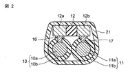
- FIG. 2 is a longitudinal sectional view taken along the line II-II ′ of FIG.
- the electronic functional member 1 has a core wire portion 5 and a sheath portion 20 that covers the core wire portion 5.
- the core wire portion 5 is electrically connected to each of the first insulation coating metal wire 10 and the second insulation coating metal wire 11 extending in the longitudinal direction, and each of the first insulation coating metal wire 10 and the second insulation coating metal wire 11.
- the electronic function part 12 made conductive is included.
- a knitted fabric 21 is used for the sheath portion 20.
- the electronic function unit 12 uses chip parts.
- the first insulating metal wire 10 is made of a metal wire 10a covered with an insulating layer 10b
- the second insulating metal wire 11 is made of a metal wire 11a covered with an insulating layer 11b.
- a part of the insulating layer 10b is removed, and a joint portion 16 is formed so as to be in contact with the exposed metal wire 10a.
- a part of the insulating layer 11b is removed, and a joint portion 17 is formed so as to be in contact with the exposed metal wire 11a.
- the electronic function part 12 has a rectangular shape, and has a pair of external electrodes 12a and 12b which are electronic function parts at both ends.
- the electronic function unit 12 is electrically connected to the metal wire 10a and the metal wire 11a by connecting the external electrode 12a to the joint 16 and connecting the external electrode 12b to the joint 17. As described above, the electrically connected electronic function unit 12 and the metal wires 10a and 11a are covered with the knitted fabric 21.
- the joints 16 and 17 may be configured as a separate structure from the joining material by plating or the like, but when the insulating layers 10b and 11b are thin, they are joined by a joining material such as solder or a conductive adhesive.
- the parts 16 and 17 can also be configured.
- a copper wire or a nickel wire can be used for the metal wire constituting the core wire portion.
- a copper wire is preferable.
- the diameter of a metal wire will not be specifically limited if it is the magnitude
- the insulating layer prevents the metal wires from directly contacting each other, and polyurethane resin, acrylic resin, or a long insulating sheet or tape can be used. In this embodiment, the insulating layer exposes part of the metal wire in order to ensure electrical continuity with the electronic function unit.
- the part of the metal wire may be other than the entire surface of the metal wire, and the area is not particularly limited.
- the electronic function part has functions of active elements such as transistors, diodes, Peltier elements, and passive elements such as resistors, capacitors, inductors, thermistors, etc., chip parts, electronic functional substance-containing films, batteries, inputs Those selected from the group consisting of elements, display elements, sensors, antennas, composite elements thereof, and integrated circuits can be used.
- active elements such as transistors, diodes, Peltier elements, and passive elements such as resistors, capacitors, inductors, thermistors, etc.
- chip parts electronic functional substance-containing films, batteries, inputs Those selected from the group consisting of elements, display elements, sensors, antennas, composite elements thereof, and integrated circuits can be used.
- the passive element may be a chip component or an electronic functional substance-containing film such as a thick film resistor, a thin film resistor, a thin film capacitor, or a thin film inductor.
- the passive element may be an organic material containing an electronic functional substance, a composite material, or a paste material.
- the electronic functional substance-containing film is formed by applying an element material, for example, a solution containing a dielectric material, to the surface of a plurality of metal wires using a known thick film printing method such as spin coating or screen printing, and performing a heat treatment. Can be formed.
- membrane patterned by the thin film process can also be used.
- a lift-off method for example, vapor deposition, sputtering, or the like can be used.
- the resist is patterned by lithography, a solution containing an element material is applied, and then the resist is peeled off, leaving only the target thin film pattern.
- the electronic function unit include an NTC thermistor, a PTC thermistor, and a Peltier element.
- the electronic function unit has a plurality of terminal units that perform signal transmission / reception with an external device.
- the terminal portion include an external electrode, a terminal, and an electrode pad.
- the two terminal portions are two terminals, one terminal can be connected to one metal wire and the other terminal can be connected to another metal wire.
- the sheath portion includes a knitted fabric that covers the core wire portion, and can be composed of one or more covering portions laminated on the outer periphery of the core wire portion.
- a knitted fabric can be used for any of the covering portions, but it is preferably used for the first covering portion that is on the core wire portion side and at least part of which is in contact with the core wire portion.
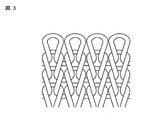
- coated part which consists of knitted fabric is shown.
- the knitted fabric 21 can form a tubular knitted fabric that covers the periphery of the core wire portion 5 by weft-knitting the knitting yarn. Weft knitting is preferable because the stitches can be made finer than warp knitting. In addition, since weft knitting stitches so that the core wire portion in the longitudinal direction is wound with the knitting yarn, the core wire portion can be relatively strongly tightened by the knitting yarn of the sheath portion, so that the sheath portion is closely attached to the core wire portion. be able to.
- thermoplastic resin examples include polyurethane resin, polyethylene resin, polyester resin, polyamide resin, and polypropylene resin.
- a thermoplastic synthetic fiber yarn made of a thermoplastic resin such as a polyethylene resin, a polyester resin, a polyamide resin, or a polypropylene resin can be used.
- the thickness of the knitting yarn is preferably 33 dtex or more and 250 dtex or less. This is because if it is smaller than 33 dtex, the knitted fabric is not sufficiently covered with the core wire portion, and if it is larger than 250 dtex, the knitting yarn is too thick and knitting by the knitting machine becomes difficult. It is also possible to use a plurality of thermoplastic synthetic fiber yarns made of thermoplastic resins having different melting points, or composite fibers made of thermoplastic synthetic fiber yarns and yarns that do not have thermoplasticity.
- the number of stitches of the same course in the knitted fabric is preferably 2 or more and 6 or less. Since the diameter of a cylindrical knitted fabric can be made small, the adhesiveness of the knitted fabric with respect to a core wire part can further be improved.
- the number of stitches per 1 cm natural length of the same wale in the knitted fabric is preferably 6 or more and 14 or less.
- the natural length means a length in a state where no tension or the like is applied, that is, a state where the natural length is naturally placed on a table. If the number of stitches per 1 cm natural length of the same wale in the knitted fabric is 6 or more, the coverage of the knitted fabric with respect to the core wire portion can be increased. Further, if the number of stitches per 1 cm natural length of the same wale in the knitted fabric is 14 or less, it is possible to suppress the occurrence of defects due to the stitching of the knitted fabric stitches due to the stitches becoming too fine. .
- the electronic functional member can be heated while being pressurized as necessary after knitting.
- the thermoplastic resin contained in the knitted fabric improves the coverage and adhesion to the core wire part of the solidified knitted fabric. Can be protected from moisture.
- the adhesiveness of a core wire part and a sheath part can further be improved by heating, heating.
- the temperature is higher than the melting point of the thermoplastic resin having a low melting point and lower than the melting point of the thermoplastic resin having a high melting point. By heating to a high melting point, the high melting point thermoplastic resin maintains the knitted fabric state, and only the low melting point thermoplastic resin is melted to increase the durability.
- the electronic functional member according to the present embodiment can be manufactured using, for example, the following method. That is, in the method for manufacturing an electronic functional member according to the present embodiment, at least two metal wires and an insulation covering the at least two metal wires so that a part of the at least two metal wires are exposed. Forming a core part including a layer and an electronic function part electrically connected to each of the at least two metal wires, and forming a sheath part covering the core part.
- the step of forming the sheath portion includes at least a step of knitting a knitted fabric by weft knitting around the core wire portion to cover the core wire portion.
- the step of forming the core wire portion can further include a step of forming a conductive pattern on the plurality of metal wires and a step of mounting at least one electronic function portion on the plurality of metal wires. For example, when two metal wires are used, as shown in FIG. 2, a part of the insulating layer on the surface of each metal wire is removed to expose the surface of the metal wire, thereby forming a joint that gives a conductive pattern. .
- the number of conductive patterns can be selected according to the number of input / output terminals of the electronic function unit and the number of electronic function units.
- the shape of the conductive pattern may be various shapes such as a linear shape, a rectangular shape, a circular shape, and a dot shape.
- a plurality of electronic function units When mounting an electronic function unit on multiple metal wires, from the viewpoint of stretchability and durability, mount the electronic function unit in a direction perpendicular to the longitudinal direction of these metal wires for a plurality of parallel metal wires. It is preferable to do.
- a plurality of electronic function units When a plurality of electronic function units are mounted in the longitudinal direction of the metal wire, a plurality of conductive patterns can be formed at predetermined intervals along the longitudinal direction of the metal wire.
- the conductive pattern can be formed using a printing method using a conductive paste or an electroplating method.
- the step of covering the core wire portion can form a tubular knitted fabric covering the periphery of the core wire portion by weft-knitting the knitting yarn using a circular knitting machine.
- a circular knitting machine for example, a known circular knitting machine described in Japanese Utility Model Laid-Open No. 60-193993 can be used.
- the electronic functional member according to the present embodiment can be manufactured by supplying it to a knitting machine and knitting it as a normal yarn.
- the electronic functional member may be combined with a normal natural fiber yarn, semi-synthetic fiber yarn, synthetic fiber yarn or the like and supplied to the knitting machine, or the electronic functional member may be supplied alone to the knitting machine.
- the electronic functional member and the normal synthetic fiber yarn are fed from the yarn path of different surface yarns and knitted, or supplied from the yarn path of the same surface yarn. There are methods such as knitting with yarns.
- the knitted fabric can be knitted by flat knitting, rib knitting, double-sided knitting, pearl knitting, or the like.
- the electronic functional member and the normal synthetic fiber yarn can be fed from the yarn path of the front yarn and the yarn path of the back yarn, respectively, and plating knitting (attachment knitting) can be used. Further, from an economic point of view, the electronic functional member can be knitted only in specific necessary parts by intarsia knitting (double-side knitting).
- the knitted fabric can include at least one power supply unit that is electrically connected to the electronic function unit. Since the electrical connection between the electronic function unit and the power supply unit can be performed by a metal wire constituting the core wire unit, it is not necessary to newly provide a lead-out line to connect the electronic function unit and the power supply unit. Thereby, the electronic function part and the power supply part can be easily connected.
- the external device that can be electrically connected to the electronic function unit is not limited to the power supply unit, and a signal generator, a transmission device, a reception device, a detection device, a measurement device, a display device, an input device, and the like can also be used.
- an electronic functional member having a built-in electric / electronic function and having excellent stretchability and durability.
- the electrical connection between the external device such as the power supply unit and the electronic function unit can be performed by the metal wire constituting the core wire unit, the connection between the external device and the electronic function unit can be easily performed.
- the sheath portion is formed of a knitted fabric and covers at least a part of the first covering portion that contacts the core wire portion and presses the first covering portion toward the core wire portion side. It has the same configuration as the electronic functional member of Embodiment 1 except that it includes the second covering portion.
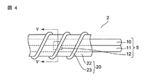
- FIG. 4 is a partially broken plan view of the electronic functional member according to the present embodiment
- FIG. 5 is a vertical cross-sectional view taken along the line V-V ′ of FIG.
- description of parts common to the first embodiment will be omitted, and only different parts will be described.
- the electronic functional member 2 has a core wire portion 5 and a sheath portion 20 that covers the core wire portion 5.
- the sheath portion 20 further includes a first covering portion 22 made of a knitted fabric and located on the core wire portion 5 side, and a second covering portion 23 wound around the first covering portion 22.
- coated part 23 can press the 1st coating
- a long member can be used for the second covering portion.
- natural fiber yarns such as cotton, hemp, and wool
- semi-synthetic fiber yarns such as cellulose
- synthetic fiber yarns such as nylon, acrylic, polyester, and polyurethane
- composite yarns that combine multiple fiber materials A tape, a string, etc.
- the first covering portion can be brought into close contact with the core wire portion without damaging the core wire portion.
- a synthetic fiber yarn containing a thermoplastic resin is used for the first covering portion
- a synthetic fiber yarn containing a thermoplastic resin can also be used for the second covering portion. After covering with the second covering portion, the synthetic fiber yarn is heated and melted, whereby the adhesion of the first covering portion to the core wire portion can be further improved after cooling.
- the electronic functional member according to the present embodiment can be manufactured by using a manufacturing method including a step of spirally winding a long member around the first covering portion after the first covering portion is formed.
- a known sheath yarn winding device described in JP-A-63-282304 is used to move the electronic functional member having the first covering portion upward or downward.
- the second covering portion can be formed by unwinding the string wound around the bobbin while winding the bobbin and winding it around the electronic functional member.
- coated part in the longitudinal direction of an electronic function member can be adjusted as needed.
- the winding interval By reducing the winding interval (or increasing the number of turns), it is possible to further improve the adhesion of the first covering portion to the core wire portion. Further, by increasing the diameter of the yarn constituting the second covering portion, the winding interval can be reduced, and the adhesion of the first covering portion to the core wire portion can be further improved.
- the adhesion of the first covering portion to the core wire portion can be further improved.
- the second covering portion is spirally wound in the longitudinal direction of the electronic functional member, while the second covering portion is wound on the second covering portion in a direction opposite to the second covering portion, and intersects the second covering portion.
- a covering part can also be provided.
- Embodiment 3 The electronic functional member according to the present embodiment has the same configuration as the electronic functional member of the first embodiment, except that an electronic functional substance-containing film is used instead of the chip component as the electronic functional part.
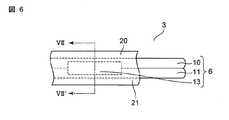
- FIG. 6 is a partially broken plan view of the electronic functional member according to the present embodiment
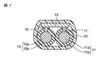
- FIG. 7 is a vertical sectional view taken along line VII-VII ′ of FIG.
- description of parts common to the first embodiment will be omitted, and only different parts will be described.
- the electronic functional member 3 has a core wire portion 6 and a sheath portion 20 that covers the core wire portion 6.
- the core wire portion 6 is disposed so as to be electrically conductive to the first insulating coating metal wire 10, the second insulating coating metal wire 11, and each of the first insulating coating metal wire 10 and the second insulating coating metal wire 11.
- the electronic functional part 13 which consists of the provided electronic functional substance containing film
- the electronic functional substance-containing film is subjected to heat treatment by applying a device raw material, for example, a solution containing a dielectric raw material, to the surface of a plurality of metal wires using a known printing method such as spin coating. Can be formed. A patterned thin film can also be used.
- the electronic functional substance includes a dielectric material, a conductive material, a magnetic material, a piezoelectric material, a semiconductor material, a pyroelectric material, and the like.
- the size and thickness of the electronic functional part mounted on the metal wire can be flexibly changed. It is possible to optimally design the electronic functional member according to the application.
- Embodiment 4 In the electronic functional member according to the present embodiment, a long insulating member is used as an insulating layer for covering the metal wire, and the outer periphery of the plurality of metal wires is covered in a band shape instead of the chip component as the electronic functional portion. Except for using the formed electronic functional substance-containing film, it has the same configuration as in the first embodiment.
- FIG. 8 is a partially broken plan view of the electronic functional member according to the present embodiment
- FIG. 9 is a longitudinal sectional view taken along the line IX-IX ′ of FIG.
- the electronic functional member 4 includes a core wire portion 7 and a sheath portion 20 that covers the core wire portion 7.
- the core wire portion 7 is formed so as to cover the metal wires 10a and 11a extending in the longitudinal direction through the insulating member 15 and the outer periphery of the metal wires 10a and 11a in a strip shape, and can be electrically connected to the metal wires 10a and 11a.
- the electronic functional material-containing film 14 is disposed on the substrate.
- a knitted fabric 21 is used for the sheath portion 20.
- the insulating member used in the present embodiment is a long insulating sheet interposed between metal wires, an insulating tape attached along the longitudinal direction of the metal wire, and formed along the longitudinal direction of the metal wire. Insulating layers can be mentioned. A polyurethane resin, an acrylic resin, or the like can be used for the insulating layer.
- the electronic functional substance-containing film is subjected to heat treatment by applying a device raw material, for example, a solution containing a dielectric raw material, to the surface of a plurality of metal wires using a known printing method such as spin coating. Can be formed. A patterned thin film element can also be used.
- a device raw material for example, a solution containing a dielectric raw material
- the size and thickness of the electronic functional part mounted on the metal wire can be flexibly changed. It is possible to optimally design the electronic functional member according to the application.
- the electronic function member of the present invention can also include a plurality of electronic function units.
- the first electronic function unit disposed so as to be electrically conductive to each metal wire of the first wiring unit made of at least two metal wires is different from the first wiring unit.
- a second electronic function unit may be provided which is arranged to be electrically conductive to each metal line of the second wiring unit made of at least two metal lines.
- a third wiring unit and a third electronic function unit, a fourth wiring unit and a fourth electronic function unit, and a fifth wiring unit and a fifth electronic function unit may be included. .
- the first electronic function unit and the other electronic function units may be different from each other, or all the electronic function units may be the same.
- a temperature sensor element for example, NTC thermistor
- a heating element for example, a PTC thermistor
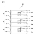
- FIG. 10 is a schematic view showing an example of the structure of the electronic functional member having a plurality of electronic functional parts described above, and the sheath is omitted.
- the core wire portion 30 has metal wires 31, 32, 33, 34, 35, and 36 each covered with an insulating layer.
- the two metal lines 31 and 32 constitute a first wiring part 37
- the other two metal lines 33 and 34 constitute a second wiring part 38
- another two metal lines 35 and 36 Constitutes a third wiring part 39.
- the first electronic functional unit 41 is joined to the joint 31a where a part of the metal wire 31 is exposed and the joint 32a where a part of the metal wire 32 is exposed.
- the second electronic function unit 42 is bonded to the bonding part 33a where a part of the metal wire 33 is exposed and the bonding part 34a where a part of the metal wire 34 is exposed.
- the third electronic function unit 43 is bonded to the bonding portion 35a where a part of the metal wire 35 is exposed and the bonding portion 36a where a part of the metal wire 36 is exposed.
- FIG. 10 shows an example in which six metal wires are arranged in parallel, the first to third electronic function units can be bundled so as not to contact each other.
- the electronic functional member of the present invention may form a circuit by interconnecting a plurality of electronic functional units with at least two metal wires. This mode will be described in more detail in the fifth embodiment below.
- the core wire portion includes a plurality of electronic functional portions, and the plurality of electronic functional portions are interconnected by at least two metal wires to form a circuit (hereinafter, the The circuit is also called a built-in circuit).
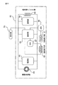
- FIG. 11 is a block diagram showing an example of the configuration of the built-in circuit.
- the circuit 60 includes a plurality of circuit element units that constitute a circuit, and the circuit element unit corresponds to an electronic function unit.
- the circuit 60 includes, as circuit element units, a passive element unit 61, an active element unit 62, a control unit 63 that controls the operation of the passive element unit 61 and the active element unit 62, and output and input of communication signals with the outside.
- a display unit 70 that displays predetermined image information from the control unit 63 is provided.
- a sensor can be used as a passive element in the passive element unit 61.
- the passive element portion is also referred to as a sensor portion.
- the sensor include a temperature sensor, an infrared sensor, a humidity sensor, a sound sensor, an optical sensor, a magnetic sensor, a pressure sensor, an acceleration sensor, and a position sensor.
- the active element unit 62 for example, a heating element or a vibrating body can be used as an active element.
- the combination of a passive element and an active element can be variously selected according to the use of an electronic functional member. For example, by using a temperature sensor as a passive element and a heating element as an active element, a temperature adjustment function can be imparted to the electronic functional member.
- the power supply unit 65 for example, a capacitor or a secondary battery can be used.
- Interconnection of a plurality of electronic function units is performed, for example, by arranging a plurality of electronic function units along the longitudinal direction of two metal wires and electrically connecting each electronic function unit to a respective metal line. be able to.
- the electronic functional member according to the present embodiment can also be made into a knitted fabric by using a method similar to the method described in the first embodiment. That is, a knitted fabric can be manufactured by supplying an electronic functional member having a built-in circuit to a knitting machine and knitting it as a normal yarn.
- the electronic functional member in addition to the effects of the first embodiment, can be further downsized by using a circuit instead of a plurality of components such as a chip. Furthermore, a knitted fabric knitted using at least a part of an electronic functional member including a sensor unit in a circuit can be attached to the measurement target without being limited to the shape of the measurement target. It can be used.
- the passive element portion and the circuit element portion other than the active element portion are not built in the electronic functional member, and an external device can be used instead.
- the external device is held by the knitted fabric, but the electrical connection between the circuit element unit other than the passive element unit and the active element unit and the external device is the metal constituting the core wire unit as described in the first embodiment. This can be done with lines.
- circuit element unit shown in FIG. 11 is an example, and various circuit element units can be used depending on the application.
- the knitting yarn is spirally wound around the first covering portion as the second covering portion has been shown.
- the second covering portion may be formed by using a knitted fabric. You may form using knitting (attached knitting).
Landscapes
- Engineering & Computer Science (AREA)
- Textile Engineering (AREA)
- Life Sciences & Earth Sciences (AREA)
- Health & Medical Sciences (AREA)
- Physics & Mathematics (AREA)
- Mechanical Engineering (AREA)
- Heart & Thoracic Surgery (AREA)
- General Health & Medical Sciences (AREA)
- Pathology (AREA)
- Biomedical Technology (AREA)
- Veterinary Medicine (AREA)
- Medical Informatics (AREA)
- Molecular Biology (AREA)
- Surgery (AREA)
- Animal Behavior & Ethology (AREA)
- Biophysics (AREA)
- Public Health (AREA)
- Manufacturing & Machinery (AREA)
- Microelectronics & Electronic Packaging (AREA)
- General Physics & Mathematics (AREA)
- Knitting Of Fabric (AREA)
- Ropes Or Cables (AREA)
- Yarns And Mechanical Finishing Of Yarns Or Ropes (AREA)
Abstract
電気電子機能を内蔵するとともに、柔軟性や耐久性に優れた電子機能部材およびそれを用いた編物製品並びに電子機能部材の製造方法を提供する。本発明の電子機能部材は、少なくとも2本の金属線と、該少なくとも2本の金属線の一部が露出するように該少なくとも2本の金属線を被覆する絶縁層と、該少なくとも2本の金属線の各々に対して電気的に導通された電子機能部とを含む芯線部と、前記芯線部を被覆する編地を含む鞘部と、を有する。
Description
本発明は、電子機能部材およびそれを用いた編物製品並びに電子機能部材の製造方法に関する。
従来、衣料品等の合成繊維の表面に機能性素材を塗布または含浸させることで合成繊維に保温性や抗菌性等の機能を付与することが広く行われている。これに対し、近年、糸や布帛に電子部品を担持させることで、糸や布帛に電気電子機能を付与することが検討されている。
例えば、特許文献1には、導電性パターンが形成された糸の表面に、電子部品を取り付けた支持体を巻き付けて固定し、糸の周囲に保持糸を巻き付けて電子部品の少なくとも一部を被覆した、複合糸およびそれを用いた布帛が記載されている。
しかしながら、特許文献1の複合糸は、保持糸自体に柔軟性がなく電子部品や配線に局所的に応力が加わると破損しやすいという問題がある。また、複合糸を用いた布帛についても曲げや引っ張り力が加わると複合糸に局所的に力が加わりやすく、断線や部品の破損が生じやすいという問題がある。
そこで、本発明は、電気電子機能を内蔵し、柔軟性や耐久性に優れた糸状の電子機能部材およびそれを用いた編物製品並びに電子機能部材の製造方法を提供することを目的とした。
上記課題を解決するため、本発明の第1の態様に係る電子機能部材は、少なくとも2本の金属線と、該少なくとも2本の金属線の一部が露出するように該少なくとも2本の金属線を被覆する絶縁層と、該少なくとも2本の金属線の各々に対して電気的に導通された電子機能部とを含む芯線部と、前記芯線部を被覆する編地を含む鞘部と、を有する。
第1の態様によれば、電気電子機能を内蔵し、曲げや衝撃に強い、編成可能な電子機能部材を提供することができる。
また、本発明の第2の態様は、第1の態様において、前記編地は、熱可塑性合成樹脂を少なくとも一部に含むものである。
第2の態様によれば、編地が熱により溶融して変形し易いので、芯線部の被覆率を大きくすることが可能である。
また、本発明の第3の態様は、第2の態様において、前記編地により前記芯線部が被覆された領域において、前記芯線が外部に対し密閉されているものである。
第3の態様によれば、鞘部の耐水性を高めることができる。
また、本発明の第4の態様は、第1の態様において、前記鞘部が、前記編地からなり前記芯線部側にある第1被覆部と、該第1被覆部の少なくとも一部を覆い、該第1被覆部を前記芯線部側に押圧する第2被覆部とを含むものである。
第4の態様によれば、第1被覆部を芯線部にさらに密着させることができる。
また、本発明の第5の態様は、第4の態様において、前記第2被覆部が、前記第1被覆部の周囲に螺旋状に巻き付けられた長尺部材であるものである。
第5の態様によれば、芯線部を傷つけることなく、第1被覆部を芯線部に密着させることができる。
また、本発明の第6の態様は、第1~第5のいずれか1つの態様において、前記電子機能部が、チップ部品、電子機能物質含有膜、電池、入力素子、表示素子、センサ、アンテナ、およびこれらの複合素子並びに集積回路から成る群から選択されるものである。
第6の態様によれば、実装する電子機能部材の大きさや厚さをより小さくできるので、電子機能部材をより細くすることが可能となる。
また、本発明の第7の態様は、第1~第6のいずれか1つの態様において、前記芯線部が複数の前記電子機能部を含み、該複数の電子機能部が前記金属線により相互接続されて回路を形成している。
第7の態様によれば、チップ等の部品に代えて回路を用いることで、電子機能部材をより小型化することができる。
また、本発明の第8の態様は、第7の態様において、前記回路が、前記電子機能部としてセンサ部を含んでいる。
第8の態様によれば、電子機能部材を計測ツールとして用いることが可能となる。
また、本発明の第9の態様は、第8の態様において、前記回路が、前記電子機能部として、さらに、前記センサ部の動作を制御する制御部と、前記センサ部からの情報を外部へ出力する通信部と、前記センサ部と前記制御部と前記通信部に電力を供給する電源部とを含んでいる。
第9の態様によれば、電子機能部材を計測ツールとして、より小型化することが可能となる。
また、本発明の第10の態様は、第1~第9のいずれか1つの態様に係る電子機能部材を少なくとも一部用いて編成してなる編物製品である。
第10の態様によれば、電気電子機能を有し、曲げや衝撃に強い編物を提供することができる。
また、本発明の第11の態様は、第10の態様において、前記少なくとも2本の金属線を介して前記電子機能部と電気的に接続されている電源部を含む編物製品である。
第11の態様によれば、外部電源を不要とすることができる。
また、本発明の第12の態様は、第10の態様において、センサ部と、前記センサ部の動作を制御する制御部と、前記センサ部からの情報を外部へ出力する通信部と、前記センサ部と前記制御部と前記通信部に電力を供給する電源部とが相互接続されてなる回路を含む前記電子機能部材を少なくとも一部に用いて編成してなる編物製品である。
第12の態様によれば、回路にセンサ部を含む電子機能部材を少なくとも一部に用いて編成した編物は、被測定対象の形状に限定されることなく、被測定対象に取り付けることができるので、新たな計測ツールとして用いることが可能となる。
また、本発明の第13の態様は、少なくとも2本の金属線と、該少なくとも2本の金属線の一部が露出するように該少なくとも2本の金属線を被覆する絶縁層と、該少なくとも2本の金属線の各々に対して電気的に導通された電子機能部とを含む芯線部を形成する工程と、前記芯線部を被覆する鞘部を形成する工程とを含み、前記の鞘部を形成する工程は、前記芯線部の周囲に緯編みにより編地を編成して、前記芯線部を被覆する工程を少なくとも含む、電子機能部材の製造方法である。
第13の態様によれば、電気電子機能を内蔵し、曲げや衝撃に強い電子機能部材を製造することができる。
また、本発明の第14の態様は、第12の態様において、前記の鞘部を形成する工程が、前記編地の周囲に、長尺部材を螺旋状に巻き付ける工程を含むものである。
第14の態様によれば、第1被覆部を芯線部にさらに密着させることができる。
本発明によれば、柔軟性や耐久性に優れた糸条の電子機能部材およびそれを用いた編物を提供することが可能となる。
以下、適宜図面を参照しながら、実施の形態を詳細に説明する。
実施の形態1
本実施の形態に係る電子機能部材は、少なくとも2本の金属線と、該少なくとも2本の金属線の一部が露出するように該少なくとも2本の金属線を被覆する絶縁層と、該少なくとも2本の金属線の各々に対して電気的に導通された電子機能部とを含む芯線部と、前記芯線部を被覆する編地を含む鞘部と、を有する。
本実施の形態に係る電子機能部材は、少なくとも2本の金属線と、該少なくとも2本の金属線の一部が露出するように該少なくとも2本の金属線を被覆する絶縁層と、該少なくとも2本の金属線の各々に対して電気的に導通された電子機能部とを含む芯線部と、前記芯線部を被覆する編地を含む鞘部と、を有する。
図1は、本実施の形態に係る電子機能部材の一部破断平面図であり、図2は、図1のII-II‘線縦断面図である。電子機能部材1は、芯線部5と、その芯線部5を被覆する鞘部20とを有している。芯線部5は、その長手方向に延びる第1絶縁被覆金属線10と第2絶縁被覆金属線11、並びに第1絶縁被覆金属線10および第2絶縁被覆金属線11の各々に対して電気的に導通させた電子機能部12を含んでいる。鞘部20には、編地21を用いている。また、電子機能部12にはチップ部品を用いている。
図2に示すように、第1絶縁被覆金属線10は、絶縁層10bにより被覆された金属線10aからなり、第2絶縁被覆金属線11は、絶縁層11bにより被覆された金属線11aからなる。絶縁層10bの一部は除去されて、露出した金属線10aに接するように接合部16が形成されている。また、絶縁層11bの一部は除去されて、露出した金属線11aに接するように接合部17が形成されている。電子機能部12は、矩形形状を有し、両端部には電子機能部である一対の外部電極12a,12bを有している。外部電極12aを接合部16に接続し、外部電極12bを接合部17に接続することで、電子機能部12は、金属線10aと金属線11aに電気的に接続されている。このように、電気的に接続された電子機能部12と金属線10a,11aの周囲は、編地21により被覆されている。なお、接合部16、17はめっき等により接合材とは別の構造体として構成してもよいが、絶縁層10b、11bが薄い場合には、はんだや導電性接着剤等の接合材により接合部16、17を構成することもできる。
芯線部を構成する金属線には、銅線やニッケル線を用いることができる。好ましくは銅線である。金属線の直径は、編地に編成できる大きさであれば特に限定されないが、1μm以上1mm以下、好ましくは1μm以上0.5mm以下である。また、絶縁層は、金属線同士が直接接触するのを防止するもので、ポリウレタン樹脂やアクリル樹脂、あるいは長尺状の絶縁シートまたはテープを用いることができる。本形態では、絶縁層は、電子機能部との電気的導通を確保するために、金属線の一部を露出させている。ここで、金属線の一部とは、金属線の全面以外であればよく、その面積は特に限定されない。
また、電子機能部は、トランジスタ、ダイオード、ペルチェ素子等の能動素子や、抵抗、コンデンサ、インダクタ、サーミスタ等の受動素子の機能を有するものであり、チップ部品、電子機能物質含有膜、電池、入力素子、表示素子、センサ、アンテナ、およびこれらの複合素子、並びに集積回路から成る群から選択されるものを用いることができる。
受動素子はチップ部品でも、電子機能物質含有膜、例えば厚膜抵抗、薄膜抵抗、薄膜コンデンサ、薄膜インダクタでもよい。また、受動素子は電子機能物質を含有する有機材料、コンポジット材料、ペースト材料であってもよい。電子機能物質含有膜は、スピンコーティングやスクリーン印刷等の公知の厚膜印刷法を用いて、複数の金属線の表面に、素子原料、例えば誘電体原料を含む溶液を塗布し、加熱処理することで形成することができる。また、薄膜プロセスによりパターニングした電子機能物質含有膜を用いることもできる。その場合、例えば、リフトオフ法、蒸着、スパッタリング等を用いることができる。リフトオフ法では、レジストを複数の金属線の表面に塗布した後、レジストをリソグラフィーによりパターニングした後、素子原料を含む溶液を塗布し、その後、レジストを剥離し、目的とする薄膜のパターンだけを残すことができる。電子機能部の具体例としては、例えば、NTCサーミスタ、PTCサーミスタ、ペルチェ素子等を挙げることができる。電子機能部材を用いた衣料にこれらの素子を用いると、例えば、NTCサーミスタを用いると衣料の温度測定が可能となる、またPTCサーミスタを用いると衣料を暖めることができ、またペルチェ素子を用いると衣料を冷やすことができる。
また、電子機能部は、外部装置との信号送受信を行う複数の端子部を有している。端子部の具体例としては、外部電極、端子、電極パッド等を挙げることができる。例えば、2つの端子部が2つの端子である場合、一方の端子を1つの金属線に接続し、他方の端子を別の金属線に接続することができる。
また、鞘部は、芯線部を被覆する編地を含むものであり、芯線部の外周に積層された1以上の被覆部で構成することができる。いずれの被覆部にも編地を用いることができるが、芯線部側にあり、少なくとも一部が芯線部に接する第1被覆部に用いることが好ましい。本実施の形態では、鞘部を編地からなる第1被覆部のみで構成した例を示している。
編地21の展開図を図3に示す。編地21は、編成糸を緯編みすることにより、芯線部5の周囲を覆う、筒状編地を形成することができる。緯編みは経編みに比べて編み目を細かくすることができるので好ましい。また、緯編みは、縦方向の芯線部を編成糸で巻き込むように編目を編成するので、鞘部の編成糸により芯線部を比較的強く締め付けることができるので、芯線部に鞘部を密着させることができる。
また、編成糸には、少なくとも一部に熱可塑性樹脂を含む糸を用いることができる。熱可塑性樹脂としては、ポリウレタン樹脂、ポリエチレン樹脂、ポリエステル樹脂、ポリアミド樹脂、ポリプロピレン樹脂等を挙げることができる。好ましくは、ポリエチレン樹脂、ポリエステル樹脂、ポリアミド樹脂、ポリプロピレン樹脂等の熱可塑性樹脂からなる熱可塑性合成繊維糸を用いることができる。また、編成糸の太さは、33デシテックス以上250デシテックス以下が好ましい。33デシテックスより小さいと、芯線部に対する編地の被覆が十分ではなく、また250デシテックスよりも大きいと、編成糸が太すぎて編み機による編成が困難になるからである。また、異なる融点の熱可塑性樹脂からなる複数の熱可塑性合成繊維糸や、熱可塑性合成繊維糸と熱可塑性を有さない糸等からなる複合繊維を用いることもできる。
また、編地における同一コースの編み目の数は、2個以上6個以下が好ましい。筒状編地の直径を小さくすることができるので、芯線部に対する編地の密着性をさらに向上させることができる。
また、編地における同一ウェールの自然長1cmあたりの編み目の数は、6個以上14個以下が好ましい。ここで、自然長とは、テンション等を与えない状態、すなわちそのまま台の上に自然に置いた状態での長さを意味する。編地における同一ウェールの自然長1cmあたりの編み目の数が6個以上であれば、芯線部に対する編地の被覆率を高めることができる。また、編地における同一ウェールの自然長1cmあたりの編み目の数が14個以下であれば、編目が細かくなり過ぎることによる、編地編目の目かぶり(タックキズ)による不良発生を抑制することができる。
また、編成糸に少なくとも一部に熱可塑性樹脂を含む糸を用いる場合、編成後、電子機能部材を、必要に応じて加圧しながら加熱することができる。編地に含まれる熱可塑性樹脂を加熱溶融させることで、冷却後、固化した編地の芯線部に対する被覆率と密着性を向上させることにより、電子機能部材や金属線を、洗濯時や汗由来の水分から保護することができる。また、加圧しながら加熱することで、芯線部と鞘部の密着性をさらに向上させることができる。編成糸に、異なる融点の熱可塑性樹脂からなる複数の熱可塑性合成繊維糸からなる複合繊維を用いる場合、融点の低い熱可塑性樹脂の融点より高く、融点の高い熱可塑性樹脂の融点よりも低い温度に加熱することで、高融点の熱可塑性樹脂は編地の状態を保ち、低融点の熱可塑性樹脂のみ溶融することで耐久性を高めることができる。
また、本実施の形態に係る電子機能部材は、例えば、以下の方法を用いて製造することができる。すなわち、本実施の形態に係る電子機能部材の製造方法は、少なくとも2本の金属線と、該少なくとも2本の金属線の一部が露出するように該少なくとも2本の金属線を被覆する絶縁層と、該少なくとも2本の金属線の各々に対して電気的に導通された電子機能部とを含む芯線部を形成する工程と、前記芯線部を被覆する鞘部を形成する工程とを含み、前記の鞘部を形成する工程は、前記芯線部の周囲に緯編みにより編地を編成して、前記芯線部を被覆する工程を少なくとも含んでいる。
芯線部を形成する工程は、さらに、複数の金属線に導電パターンを形成する工程と、少なくとも1つの電子機能部を複数の金属線に実装する工程を含むことができる。例えば、2本の金属線を用いる場合、図2に示すように、各金属線の表面の絶縁層の一部を削除して金属線の表面を露出させ、導電パターンを与える接合部を形成する。導電パターンの数は、電子機能部の入出力端子数や電子機能部の数に応じて選択することができる。また導電パターンの形状は、線状、矩形状、円形状、点状等種々の形状を用いることができる。電子機能部を複数の金属線に実装する場合、伸縮性および耐久性の観点から、互いに平行な複数の金属線に対し、それら複数の金属線に長手方向に垂直な方向に電子機能部を実装することが好ましい。また複数の電子機能部を金属線の長手方向に実装する場合、金属線の長手方向に沿って所定間隔で複数の導電パターンを形成することができる。導電パターンは、導電ペーストを用いる印刷法や、電気めっき法を用いて形成することができる。
芯線部を被覆する工程は、丸編機を用い、編成糸を緯編みすることにより、芯線部の周囲を覆う、筒状編地を形成することができる。丸編機には、例えば実開昭60-193993号公報に記載されているような公知の丸編機を用いることができる。
また、本実施の形態に係る電子機能部材は、編機に供給し、通常の糸として編成することで、編物を製造することができる。電子機能部材は、通常の天然繊維糸、半合成繊維糸、合成繊維糸等と組み合わせ、編機に給糸してもよく、あるいは電子機能部材を単独で編機に供給することもできる。電子機能部材を通常の合成繊維糸と組み合わせる方法としては、例えば、電子機能部材と通常の合成繊維糸を、異なる表糸の糸道から給糸し編成する方法、同じ表糸の糸道から給糸して引き揃えて編成する方法等がある。編地は、平編み、リブ編み、両面編み、パール編み等で編成することが出来る。また、電子機能部材と通常の合成繊維糸を、それぞれ表糸の糸道と裏糸の糸道から給糸し、プレーティング編み(添え編み)を用いることができる。また、経済的観点からは、電子機能部材をインターシャ編み(両面編み)で特定の必要な部分だけに編みこむことができる。
また、編物は、電子機能部に電気的に接続されている少なくとも1つの電源部を含むことができる。電子機能部と電源部との電気的接続は芯線部を構成する金属線により行うことができるので、新たに引き出し線を設けて電子機能部と電源部とを接続することが不要となる。これにより、電子機能部と電源部の接続を簡単に行うことができる。電子機能部と電気的に接続できる外部装置は電源部に限定されず、信号発生器、送信装置、受信装置、検出装置、測定装置、表示装置、入力装置等も用いることができる。
本実施の形態によれば、電気電子機能を内蔵するとともに、伸縮性や耐久性に優れた電子機能部材を提供することができる。また、電源部等の外部装置と電子機能部との電気的接続を、芯線部を構成する金属線により行うことができるので、外部装置と電子機能部との接続を簡単に行うことができる。
実施の形態2
本実施の形態に係る電子機能部材は、鞘部が、編地からなり芯線部に接する第1被覆部と、第1被覆部の少なくとも一部を覆い、第1被覆部を芯線部側に押圧する第2被覆部とを含む以外は、実施の形態1の電子機能部材と同様の構成を有している。
本実施の形態に係る電子機能部材は、鞘部が、編地からなり芯線部に接する第1被覆部と、第1被覆部の少なくとも一部を覆い、第1被覆部を芯線部側に押圧する第2被覆部とを含む以外は、実施の形態1の電子機能部材と同様の構成を有している。
図4は、本実施の形態に係る電子機能部材の一部破断平面図であり、図5は図4のV-V‘線縦断面図である。以下、実施の形態1と共通する部分の説明は省略し、異なる部分のみについて説明する。
電子機能部材2は、芯線部5と、その芯線部5を被覆する鞘部20とを有している。鞘部20は、さらに編地からなり芯線部5側にある第1被覆部22と、第1被覆部22に巻き付けられた第2被覆部23とを含んでいる。第2被覆部23は、第1被覆部22を芯線部5側に押圧し、第1被覆部22を芯線部5にさらに密着させることができる。
第2被覆部には、長尺部材を用いることができる。長尺部材には、綿や麻、毛などの天然繊維糸、セルロースなどの半合成繊維糸、ナイロン、アクリル、ポリエステル、ポリウレタンなどの合成繊維糸のほか、複数の繊維素材を組み合わせた複合糸、テープや紐等を挙げることができる。長尺部材を用いることで、芯線部を傷つけることなく、第1被覆部を芯線部に密着させることができる。また、第1被覆部に熱可塑性樹脂を含む合成繊維糸を用いた場合、第2被覆部にも熱可塑性樹脂を含む合成繊維糸を用いることができる。第2被覆部で被覆後、合成繊維糸を加熱溶融させることで、冷却後、第1被覆部の芯線部に対する密着性をさらに向上させることができる。
本実施の形態に係る電子機能部材は、第1被覆部形成後、第1被覆部の周囲に長尺部材を螺旋状に巻き付ける工程を含む製造方法を用いて製造することができる。第2被覆部は、例えば特開昭63-282304号公報に記載されている公知の鞘糸巻き付け装置を用いることで、上方向または下方向に第1被覆部を形成した電子機能部材を移動させながら、ボビンに巻回された紐を、ボビンを回転させながら繰り出して、電子機能部材に巻き付けることで第2被覆部を形成することができる。なお、電子機能部材の長手方向における第2被覆部の巻線間隔は、必要に応じて調整することができる。巻線間隔を小さくすることで(あるいは巻回数を増やすことで)、第1被覆部の芯線部に対する密着性をさらに向上させることができる。また、第2被覆部を構成する糸の径を大きくすることで、巻線間隔を小さくして、第1被覆部の芯線部に対する密着性をさらに向上させることもできる。
本実施の形態によれば、実施の形態1の効果に加え、第2被覆部を設けることで、第1被覆部の芯線部に対する密着性をさらに向上させることができる。
なお、本実施の形態では、第2被覆部を設けた例を示したが、必要に応じてさらに被覆部を設けることもできる。例えば、第2被覆部は、電子機能部材の長手方向に螺旋状に巻き付ける一方、第2被覆部の上に、第2被覆部とは逆方向に巻き付けられ、第2被覆部と交差する第3被覆部を設けることもできる。第3被覆部を設けることにより、第1被覆部の芯線部に対する密着性をさらに向上させることができる。
実施の形態3
本実施の形態に係る電子機能部材は、電子機能部としてチップ部品に代えて電子機能物質含有膜を用いた以外は、実施の形態1の電子機能部材と同様の構成を有している。
本実施の形態に係る電子機能部材は、電子機能部としてチップ部品に代えて電子機能物質含有膜を用いた以外は、実施の形態1の電子機能部材と同様の構成を有している。
図6は、本実施の形態に係る電子機能部材の一部破断平面図であり、図7は図6のVII-VII‘線縦断面図である。以下、実施の形態1と共通する部分の説明は省略し、異なる部分のみについて説明する。
電子機能部材3は、芯線部6と、その芯線部6を被覆する鞘部20とを有している。芯線部6は、第1絶縁被覆金属線10と、第2絶縁被覆金属線11と、第1絶縁被覆金属線10および第2絶縁被覆金属線11の各々に対して電気的に導通可能に配設された電子機能物質含有膜からなる電子機能部13を含んでいる。
上述したように、電子機能物質含有膜は、スピンコーティング等の公知の印刷法を用いて、複数の金属線の表面に、素子原料、例えば誘電体原料を含む溶液を塗布し、加熱処理することで形成することができる。また、パターニングした薄膜を用いることもできる。ここで、電子機能物質には、誘電材料、導電材料、磁性材料、圧電材料、半導体材料、焦電材料等が含まれる。
本実施の形態によれば、実施の形態1の効果に加え、電子機能物質含有膜を用いることで、金属線に実装する電子機能部の大きさや厚さを柔軟に変更することができるので、電子機能部材を用途に応じて最適設計することが可能となる。
実施の形態4
本実施の形態に係る電子機能部材は、金属線を被覆する絶縁層として長尺の絶縁部材を用い、電子機能部としてチップ部品に代えて、複数の金属線の外周を帯状に被覆するように形成された電子機能物質含有膜を用いた以外は、実施の形態1と同様の構成を有している。
本実施の形態に係る電子機能部材は、金属線を被覆する絶縁層として長尺の絶縁部材を用い、電子機能部としてチップ部品に代えて、複数の金属線の外周を帯状に被覆するように形成された電子機能物質含有膜を用いた以外は、実施の形態1と同様の構成を有している。
図8は、本実施の形態に係る電子機能部材の一部破断平面図であり、図9は図8のIX-IX‘線縦断面図である。電子機能部材4は、芯線部7と、芯線部7を被覆する鞘部20とを有している。芯線部7は、絶縁部材15を介して長手方向に延びる金属線10a,11aと、金属線10a,11aの外周を帯状に被覆するように形成され、金属線10a,11aと電気的に導通可能に配設された電子機能物質含有膜14を含んでいる。鞘部20には、編地21を用いている。
本実施の形態に用いる絶縁部材としては、金属線の間に介在する長尺状の絶縁シート、金属線の長手方向に沿って貼り付けられた絶縁テープ、金属線の長手方向に沿って形成された絶縁層等を挙げることができる。絶縁層には、ポリウレタン樹脂やアクリル樹脂等を用いることができる。
上述したように、電子機能物質含有膜は、スピンコーティング等の公知の印刷法を用いて、複数の金属線の表面に、素子原料、例えば誘電体原料を含む溶液を塗布し、加熱処理することで形成することができる。また、パターニングした薄膜素子を用いることもできる。
本実施の形態によれば、実施の形態1の効果に加え、電子機能物質含有膜を用いることで、金属線に実装する電子機能部の大きさや厚さを柔軟に変更することができるので、電子機能部材を用途に応じて最適設計することが可能となる。
実施の形態1~4では、電子機能部が1個の例について説明したが、本発明の電子機能部材は、複数の電子機能部を備えることもできる。例えば、少なくとも2本の金属線から成る第1の配線部の各々の金属線に対して電気的に導通可能に配設された第1の電子機能部と、前記第1の配線部とは異なる、少なくとも2本の金属線から成る第2の配線部の各々の金属線に対して電気的に導通可能に配設された第2の電子機能部を有していてもよい。同様に、第3の配線部と第3の電子機能部、第4の配線部と第4の電子機能部、さらに第5の配線部と第5の電子機能部等を有していてもよい。第1の電子機能部と他の電子機能部は互いに異なっていてもよく、あるいはすべての電子機能部が同じでもよい。例えば、第1の電子機能部に温度センサ素子(例えばNTCサーミスタ)を用い、第2の電子機能部に発熱素子(例えばPTCサーミスタ)を用いることができる。
図10は、上述した、複数の電子機能部を備えた電子機能部材の構造の一例を示す模式図であり、鞘部は省略している。芯線部30は、それぞれが絶縁層で被覆された金属線31,32,33,34,35,36を有している。2本の金属線31,32は、第1の配線部37を構成し、別の2本の金属線33,34は第2の配線部38を構成、別の2本の金属線35,36は第3の配線部39を構成している。金属線31の一部が露出した接合部31aと、金属線32の一部が露出した接合部32aとには第1の電子機能部41が接合されている。また、金属線33の一部が露出した接合部33aと、金属線34の一部が露出した接合部34aとには第2の電子機能部42が接合されている。また、金属線35の一部が露出した接合部35aと、金属線36の一部が露出した接合部36aとには第3の電子機能部43が接合されている。図10では、6本の金属線を並列に配置した例を示したが、第1~第3の電子機能部が互いに接触しないように束ねることもできる。
また、本発明の電子機能部材は、複数の電子機能部を少なくとも2本の金属線により相互接続して回路を形成するようにしてもよい。この形態については、以下の実施の形態5で、さらに詳しく説明する。
実施の形態5
本実施の形態に係る電子機能部材では、芯線部が複数の電子機能部を含み、該複数の電子機能部が少なくとも2本の金属線により相互接続されて回路を形成している(以下、その回路を内蔵回路ともいう)。図11は、その内蔵回路の構成の一例を示すブロック図である。回路60は、回路を構成する複数の回路素子部を有し、該回路素子部が電子機能部に相当する。回路60は、回路素子部として、受動素子部61と、能動素子部62と、受動素子部61と能動素子部62の動作を制御する制御部63と、外部との通信信号の出力と入力を行う通信部64と、各部に電力を供給する電源部65と、受動素子部61からのデータ信号をA/D変換して制御部63に出力するA/Dコンバータ部66と、制御部63からの制御信号をD/A変換して能動素子部62に供給するD/Aコンバータ部67と、外部との無線送受信を行う送受信アンテナ部68と、外部からの電力用電波を受信し、その電力用電波から生成した電力を電源部65に出力する無線充電部69と、を有している。また、外部装置として、制御部63からの所定の画像情報を表示する表示部70を有している。
本実施の形態に係る電子機能部材では、芯線部が複数の電子機能部を含み、該複数の電子機能部が少なくとも2本の金属線により相互接続されて回路を形成している(以下、その回路を内蔵回路ともいう)。図11は、その内蔵回路の構成の一例を示すブロック図である。回路60は、回路を構成する複数の回路素子部を有し、該回路素子部が電子機能部に相当する。回路60は、回路素子部として、受動素子部61と、能動素子部62と、受動素子部61と能動素子部62の動作を制御する制御部63と、外部との通信信号の出力と入力を行う通信部64と、各部に電力を供給する電源部65と、受動素子部61からのデータ信号をA/D変換して制御部63に出力するA/Dコンバータ部66と、制御部63からの制御信号をD/A変換して能動素子部62に供給するD/Aコンバータ部67と、外部との無線送受信を行う送受信アンテナ部68と、外部からの電力用電波を受信し、その電力用電波から生成した電力を電源部65に出力する無線充電部69と、を有している。また、外部装置として、制御部63からの所定の画像情報を表示する表示部70を有している。
受動素子部61には、受動素子として、例えばセンサを用いることができる。その場合、受動素子部をセンサ部ともいう。センサとしては、温度センサ、赤外線センサ、湿度センサ、音センサ、光センサ、磁気センサ、圧力センサ、加速度センサ、位置センサ等を挙げることができる。また、能動素子部62には、能動素子として、例えば、発熱体や振動体を用いることができる。受動素子と能動素子の組み合わせは、電子機能部材の用途に応じて様々に選択することができる。例えば、受動素子に温度センサを用い、能動素子に発熱体を用いることで、電子機能部材に温度調整機能を付与することができる。また、電源部65には、例えばコンデンサや二次電池を用いることができる。
複数の電子機能部の相互接続は、例えば、2本の金属線の長手方向に沿って複数の電子機能部を配置し、各電子機能部をそれぞれの金属線に電気的に導通させることにより行うことができる。
本実施の形態に係る電子機能部材も、実施の形態1に記載した方法と同様の方法を用いることで編物とすることができる。すなわち、内蔵回路を有する電子機能部材を編機に供給し、通常の糸として編成することで、編物を製造することができる。
本実施の形態によれば、実施の形態1の効果に加え、チップ等の複数の部品に代えて回路を用いることで、電子機能部材をより小型化することができる。さらに、回路にセンサ部を含む電子機能部材を少なくとも一部に用いて編成した編物は、被測定対象の形状に限定されることなく、被測定対象に取り付けることができるので、新たな計測ツールとして用いることが可能となる。
なお、本実施の形態では、受動素子部と能動素子部以外の回路素子部については、電子機能部材に内蔵させず、代わりに外部装置を用いることもできる。その場合、外部装置は編物に保持させるが、受動素子部と能動素子部以外の回路素子部と外部装置との電気的接続は、実施の形態1で説明したように、芯線部を構成する金属線により行うことができる。
また、図11に示した回路素子部は一例であり、用途に応じて種々の回路素子部を用いることが可能である。
以上、本発明の実施の形態について説明したが、それらは例示であって、本発明の範囲内で種々の変形例が可能であることを当業者は理解することができる。例えば、実施の形態2では、第2被覆部として編成糸を螺旋状に第1被覆部に巻き付けた例を示したが、編地を用いて第2被覆部を形成してもよく、プレーティング編み(添え編み)を用いて形成してもよい。
本発明によれば、電子電気機能を内蔵した衣料品等の新規な編物製品を提供することが可能となる。
1,2,3,4 電子機能部材
5,6,7 芯線部
10 第1絶縁被覆金属線
11 第2絶縁被覆金属線
10a,11a 金属線
10b,11b 絶縁層
12,13,14 電子機能部
12a,12b 外部電極
15 絶縁部材
16,17 接合部
20 鞘部
21 編地
22 第1被覆部
23 第2被覆部
30 芯線部
31,32,33 金属線
34,35,36 金属線
31a,32a,33a 接合部
34a,35a,36a 接合部
37 第1の配線部
38 第2の配線部
39 第3の配線部
41 第1の電子機能部
42 第2の電子機能部
43 第3の電子機能部
60 回路
61 受動素子部
62 能動素子部
63 制御部
64 通信部
65 電源部
66 A/Dコンバータ部
67 D/Aコンバータ部
68 送受信アンテナ部
69 無線充電部
5,6,7 芯線部
10 第1絶縁被覆金属線
11 第2絶縁被覆金属線
10a,11a 金属線
10b,11b 絶縁層
12,13,14 電子機能部
12a,12b 外部電極
15 絶縁部材
16,17 接合部
20 鞘部
21 編地
22 第1被覆部
23 第2被覆部
30 芯線部
31,32,33 金属線
34,35,36 金属線
31a,32a,33a 接合部
34a,35a,36a 接合部
37 第1の配線部
38 第2の配線部
39 第3の配線部
41 第1の電子機能部
42 第2の電子機能部
43 第3の電子機能部
60 回路
61 受動素子部
62 能動素子部
63 制御部
64 通信部
65 電源部
66 A/Dコンバータ部
67 D/Aコンバータ部
68 送受信アンテナ部
69 無線充電部
Claims (14)
- 少なくとも2本の金属線と、該少なくとも2本の金属線の一部が露出するように該少なくとも2本の金属線を被覆する絶縁層と、該少なくとも2本の金属線の各々に対して電気的に導通された電子機能部とを含む芯線部と、
前記芯線部を被覆する編地を含む鞘部と、を有する電子機能部材。 - 前記編地は、熱可塑性合成樹脂を少なくとも一部に含む請求項1に記載の電子機能部材。
- 前記編地により前記芯線部が被覆された領域において、前記芯線部が外部に対し密閉されている請求項2記載の電子機能部材。
- 前記鞘部は、前記編地からなる前記芯線部側の第1被覆部と、該第1被覆部の少なくとも一部を覆い、該第1被覆部を前記芯線部側に押圧する第2被覆部とを含む、請求項1~3のいずれか1項に記載の電子機能部材。
- 前記第2被覆部は、前記第1被覆部の周囲に螺旋状に巻き付けられた長尺部材である、請求項4記載の電子機能部材。
- 前記電子機能部は、チップ部品、電子機能物質含有膜、電池、入力素子、表示素子、センサ、アンテナ、およびこれらの複合素子並びに集積回路から成る群から選択される、請求項1~5のいずれか1項に記載の電子機能部材。
- 前記芯線部が複数の前記電子機能部を含み、該複数の電子機能部が前記少なくとも2本の金属線により相互接続されて回路を形成している、請求項1~6のいずれか1項に記載の電子機能部材。
- 前記回路が、前記電子機能部としてセンサ部を含む、請求項7記載の電子機能部材。
- 前記回路が、前記電子機能部として、さらに、前記センサ部の動作を制御する制御部と、前記センサ部からの情報を外部へ出力する通信部と、前記センサ部と前記制御部と前記通信部に電力を供給する電源部とを含む、請求項8記載の電子機能部材。
- 請求項1~9のいずれか1項に記載の電子機能部材を少なくとも一部に用いて編成してなる編物製品。
- 前記少なくとも2本の金属線を介して前記電子機能部と電気的に接続されている電源部を含む、請求項10記載の編物製品。
- センサ部と、前記センサ部の動作を制御する制御部と、前記センサ部からの情報を外部へ出力する通信部と、前記センサ部と前記制御部と前記通信部に電力を供給する電源部とが前記少なくとも2本の金属線により相互接続されてなる回路を含む前記電子機能部材を少なくとも一部に用いて編成してなる、請求項10記載の編物製品。
- 少なくとも2本の金属線と、該少なくとも2本の金属線の一部が露出するように該少なくとも2本の金属線を被覆する絶縁層と、該少なくとも2本の金属線の各々に対して電気的に導通された電子機能部とを含む芯線部を形成する工程と、
前記芯線部を被覆する鞘部を形成する工程とを含み、
前記の鞘部を形成する工程は、前記芯線部の周囲に緯編みにより編地を編成して、前記芯線部を被覆する工程を少なくとも含む、電子機能部材の製造方法。 - 前記の鞘部を形成する工程は、前記編地の周囲に、長尺部材を螺旋状に巻き付ける工程を含む、請求項13記載の電子機能部材の製造方法。
Priority Applications (3)
| Application Number | Priority Date | Filing Date | Title |
|---|---|---|---|
| JP2018531768A JP6716701B2 (ja) | 2016-08-04 | 2017-06-16 | 電子機能部材およびそれを用いた編物製品並びに電子機能部材の製造方法 |
| CN201780047643.3A CN109563653A (zh) | 2016-08-04 | 2017-06-16 | 电子功能构件、使用了该电子功能构件的织物制品以及电子功能构件的制造方法 |
| US16/239,970 US20190156972A1 (en) | 2016-08-04 | 2019-01-04 | Electronic functional member, knitted product using the same, and method for manufacturing electronic functional member |
Applications Claiming Priority (4)
| Application Number | Priority Date | Filing Date | Title |
|---|---|---|---|
| JP2016153315 | 2016-08-04 | ||
| JP2016-153315 | 2016-08-04 | ||
| JP2017083140 | 2017-04-19 | ||
| JP2017-083140 | 2017-04-19 |
Related Child Applications (1)
| Application Number | Title | Priority Date | Filing Date |
|---|---|---|---|
| US16/239,970 Continuation US20190156972A1 (en) | 2016-08-04 | 2019-01-04 | Electronic functional member, knitted product using the same, and method for manufacturing electronic functional member |
Publications (1)
| Publication Number | Publication Date |
|---|---|
| WO2018025525A1 true WO2018025525A1 (ja) | 2018-02-08 |
Family
ID=61073949
Family Applications (1)
| Application Number | Title | Priority Date | Filing Date |
|---|---|---|---|
| PCT/JP2017/022411 Ceased WO2018025525A1 (ja) | 2016-08-04 | 2017-06-16 | 電子機能部材およびそれを用いた編物製品並びに電子機能部材の製造方法 |
Country Status (4)
| Country | Link |
|---|---|
| US (1) | US20190156972A1 (ja) |
| JP (1) | JP6716701B2 (ja) |
| CN (1) | CN109563653A (ja) |
| WO (1) | WO2018025525A1 (ja) |
Families Citing this family (3)
| Publication number | Priority date | Publication date | Assignee | Title |
|---|---|---|---|---|
| EP3722472B1 (de) * | 2019-04-08 | 2021-08-11 | KARL MAYER STOLL R&D GmbH | Flachstrickmaschine mit vorrichtung zum einführen von einlegeteilen in ein gestrick |
| WO2020210644A1 (en) | 2019-04-10 | 2020-10-15 | Propel, LLC | Knitted textiles with conductive traces of a hybrid yarn and methods of knitting the same |
| CN115976700A (zh) * | 2022-12-27 | 2023-04-18 | 江南织造府(宁波)线业有限公司 | 一种导电纱线的制造工艺 |
Citations (2)
| Publication number | Priority date | Publication date | Assignee | Title |
|---|---|---|---|---|
| JPS5928054Y2 (ja) * | 1982-08-02 | 1984-08-14 | 武 山崎 | 金銀加工糸 |
| WO2013057830A1 (ja) * | 2011-10-21 | 2013-04-25 | 京セミ株式会社 | 半導体機能素子付き機能糸とその製造方法 |
Family Cites Families (5)
| Publication number | Priority date | Publication date | Assignee | Title |
|---|---|---|---|---|
| JP3726998B2 (ja) * | 1999-04-01 | 2005-12-14 | 株式会社村田製作所 | 表面波装置 |
| GB0108950D0 (en) * | 2001-04-10 | 2001-05-30 | Leonard Philip N | Personal computer systems |
| US6686038B2 (en) * | 2002-02-25 | 2004-02-03 | Koninklijke Philips Electronics N.V. | Conductive fiber |
| US7592276B2 (en) * | 2002-05-10 | 2009-09-22 | Sarnoff Corporation | Woven electronic textile, yarn and article |
| KR101038755B1 (ko) * | 2008-10-09 | 2011-06-03 | 조인셋 주식회사 | 세라믹 칩 어셈블리 |
-
2017
- 2017-06-16 CN CN201780047643.3A patent/CN109563653A/zh active Pending
- 2017-06-16 WO PCT/JP2017/022411 patent/WO2018025525A1/ja not_active Ceased
- 2017-06-16 JP JP2018531768A patent/JP6716701B2/ja active Active
-
2019
- 2019-01-04 US US16/239,970 patent/US20190156972A1/en not_active Abandoned
Patent Citations (2)
| Publication number | Priority date | Publication date | Assignee | Title |
|---|---|---|---|---|
| JPS5928054Y2 (ja) * | 1982-08-02 | 1984-08-14 | 武 山崎 | 金銀加工糸 |
| WO2013057830A1 (ja) * | 2011-10-21 | 2013-04-25 | 京セミ株式会社 | 半導体機能素子付き機能糸とその製造方法 |
Also Published As
| Publication number | Publication date |
|---|---|
| JPWO2018025525A1 (ja) | 2019-01-17 |
| US20190156972A1 (en) | 2019-05-23 |
| JP6716701B2 (ja) | 2020-07-01 |
| CN109563653A (zh) | 2019-04-02 |
Similar Documents
| Publication | Publication Date | Title |
|---|---|---|
| US12133743B2 (en) | Fabric-based items with stretchable bands | |
| JP6813896B2 (ja) | 配線フィルム、デバイス転写シート及びテキスタイル型デバイス | |
| US10472742B1 (en) | Fabric-based items with fusible insulating strands | |
| CN110249714B (zh) | 印刷电路板生物感测服装连接器 | |
| JP6932774B2 (ja) | 繊維製品およびその製造方法 | |
| US20180195210A1 (en) | Insulated Conductive Strands With Polymer Cores | |
| US10905006B2 (en) | Textile electronic device for smart clothing | |
| JP6716701B2 (ja) | 電子機能部材およびそれを用いた編物製品並びに電子機能部材の製造方法 | |
| JPWO2018173749A1 (ja) | 導電性複合シート | |
| EP3251473A1 (en) | Flexible device module for fabric layer assembly and method for production | |
| JP2019220247A (ja) | 端子接続構造及び端子接続方法 | |
| KR101715313B1 (ko) | 스마트 의류용 전도성 테이프 및 그 부착방법 | |
| JP6822855B2 (ja) | 伸縮配線及び伸縮配線の製造方法 | |
| JP7297611B2 (ja) | 電気中継部材 | |
| KR101237911B1 (ko) | 직물형 압력센서 패키지 제조방법 | |
| KR20150078803A (ko) | 섬유기반 도전선 | |
| JP2020072049A (ja) | 伸縮性配線部材、伸縮性配線部材の製造方法、及び伸縮性配線付布帛 | |
| KR101619528B1 (ko) | 도전체와 그 제조방법 | |
| US20210079569A1 (en) | Forming Electrical Connections in Fabric-Based Items | |
| US20260040444A1 (en) | Fabric with Electrical Components | |
| JP5164205B2 (ja) | 手袋 | |
| JP2015222626A (ja) | シールド電線、ハーネス、電気回路、布地、衣服及びシート | |
| WO2017102615A1 (en) | Method for manufacturing a panel of fabric and kit for creating a wearable electronic item | |
| US20260001270A1 (en) | Fabric with Digitally Controlled Characteristics | |
| JP2020041229A (ja) | 複合糸および複合連続糸 |
Legal Events
| Date | Code | Title | Description |
|---|---|---|---|
| WWE | Wipo information: entry into national phase |
Ref document number: 2018531768 Country of ref document: JP |
|
| 121 | Ep: the epo has been informed by wipo that ep was designated in this application |
Ref document number: 17836632 Country of ref document: EP Kind code of ref document: A1 |
|
| NENP | Non-entry into the national phase |
Ref country code: DE |
|
| 122 | Ep: pct application non-entry in european phase |
Ref document number: 17836632 Country of ref document: EP Kind code of ref document: A1 |