WO2018025481A1 - 車載カメラ、車載用カメラ装置、並びに車載カメラの支持方法 - Google Patents
車載カメラ、車載用カメラ装置、並びに車載カメラの支持方法 Download PDFInfo
- Publication number
- WO2018025481A1 WO2018025481A1 PCT/JP2017/020098 JP2017020098W WO2018025481A1 WO 2018025481 A1 WO2018025481 A1 WO 2018025481A1 JP 2017020098 W JP2017020098 W JP 2017020098W WO 2018025481 A1 WO2018025481 A1 WO 2018025481A1
- Authority
- WO
- WIPO (PCT)
- Prior art keywords
- vehicle
- vehicle camera
- substrate
- image
- condensing optical
- Prior art date
- Legal status (The legal status is an assumption and is not a legal conclusion. Google has not performed a legal analysis and makes no representation as to the accuracy of the status listed.)
- Ceased
Links
Images



Classifications
-
- B—PERFORMING OPERATIONS; TRANSPORTING
- B60—VEHICLES IN GENERAL
- B60R—VEHICLES, VEHICLE FITTINGS, OR VEHICLE PARTS, NOT OTHERWISE PROVIDED FOR
- B60R11/00—Arrangements for holding or mounting articles, not otherwise provided for
- B60R11/04—Mounting of cameras operative during drive; Arrangement of controls thereof relative to the vehicle
-
- G—PHYSICS
- G02—OPTICS
- G02B—OPTICAL ELEMENTS, SYSTEMS OR APPARATUS
- G02B7/00—Mountings, adjusting means, or light-tight connections, for optical elements
- G02B7/02—Mountings, adjusting means, or light-tight connections, for optical elements for lenses
-
- G—PHYSICS
- G03—PHOTOGRAPHY; CINEMATOGRAPHY; ANALOGOUS TECHNIQUES USING WAVES OTHER THAN OPTICAL WAVES; ELECTROGRAPHY; HOLOGRAPHY
- G03B—APPARATUS OR ARRANGEMENTS FOR TAKING PHOTOGRAPHS OR FOR PROJECTING OR VIEWING THEM; APPARATUS OR ARRANGEMENTS EMPLOYING ANALOGOUS TECHNIQUES USING WAVES OTHER THAN OPTICAL WAVES; ACCESSORIES THEREFOR
- G03B15/00—Special procedures for taking photographs; Apparatus therefor
-
- G—PHYSICS
- G03—PHOTOGRAPHY; CINEMATOGRAPHY; ANALOGOUS TECHNIQUES USING WAVES OTHER THAN OPTICAL WAVES; ELECTROGRAPHY; HOLOGRAPHY
- G03B—APPARATUS OR ARRANGEMENTS FOR TAKING PHOTOGRAPHS OR FOR PROJECTING OR VIEWING THEM; APPARATUS OR ARRANGEMENTS EMPLOYING ANALOGOUS TECHNIQUES USING WAVES OTHER THAN OPTICAL WAVES; ACCESSORIES THEREFOR
- G03B17/00—Details of cameras or camera bodies; Accessories therefor
- G03B17/02—Bodies
-
- G—PHYSICS
- G03—PHOTOGRAPHY; CINEMATOGRAPHY; ANALOGOUS TECHNIQUES USING WAVES OTHER THAN OPTICAL WAVES; ELECTROGRAPHY; HOLOGRAPHY
- G03B—APPARATUS OR ARRANGEMENTS FOR TAKING PHOTOGRAPHS OR FOR PROJECTING OR VIEWING THEM; APPARATUS OR ARRANGEMENTS EMPLOYING ANALOGOUS TECHNIQUES USING WAVES OTHER THAN OPTICAL WAVES; ACCESSORIES THEREFOR
- G03B17/00—Details of cameras or camera bodies; Accessories therefor
- G03B17/02—Bodies
- G03B17/17—Bodies with reflectors arranged in beam forming the photographic image, e.g. for reducing dimensions of camera
-
- G—PHYSICS
- G03—PHOTOGRAPHY; CINEMATOGRAPHY; ANALOGOUS TECHNIQUES USING WAVES OTHER THAN OPTICAL WAVES; ELECTROGRAPHY; HOLOGRAPHY
- G03B—APPARATUS OR ARRANGEMENTS FOR TAKING PHOTOGRAPHS OR FOR PROJECTING OR VIEWING THEM; APPARATUS OR ARRANGEMENTS EMPLOYING ANALOGOUS TECHNIQUES USING WAVES OTHER THAN OPTICAL WAVES; ACCESSORIES THEREFOR
- G03B17/00—Details of cameras or camera bodies; Accessories therefor
- G03B17/56—Accessories
-
- G—PHYSICS
- G03—PHOTOGRAPHY; CINEMATOGRAPHY; ANALOGOUS TECHNIQUES USING WAVES OTHER THAN OPTICAL WAVES; ELECTROGRAPHY; HOLOGRAPHY
- G03B—APPARATUS OR ARRANGEMENTS FOR TAKING PHOTOGRAPHS OR FOR PROJECTING OR VIEWING THEM; APPARATUS OR ARRANGEMENTS EMPLOYING ANALOGOUS TECHNIQUES USING WAVES OTHER THAN OPTICAL WAVES; ACCESSORIES THEREFOR
- G03B17/00—Details of cameras or camera bodies; Accessories therefor
- G03B17/56—Accessories
- G03B17/561—Support related camera accessories
-
- G—PHYSICS
- G03—PHOTOGRAPHY; CINEMATOGRAPHY; ANALOGOUS TECHNIQUES USING WAVES OTHER THAN OPTICAL WAVES; ELECTROGRAPHY; HOLOGRAPHY
- G03B—APPARATUS OR ARRANGEMENTS FOR TAKING PHOTOGRAPHS OR FOR PROJECTING OR VIEWING THEM; APPARATUS OR ARRANGEMENTS EMPLOYING ANALOGOUS TECHNIQUES USING WAVES OTHER THAN OPTICAL WAVES; ACCESSORIES THEREFOR
- G03B19/00—Cameras
- G03B19/02—Still-picture cameras
- G03B19/04—Roll-film cameras
- G03B19/07—Roll-film cameras having more than one objective
-
- G—PHYSICS
- G03—PHOTOGRAPHY; CINEMATOGRAPHY; ANALOGOUS TECHNIQUES USING WAVES OTHER THAN OPTICAL WAVES; ELECTROGRAPHY; HOLOGRAPHY
- G03B—APPARATUS OR ARRANGEMENTS FOR TAKING PHOTOGRAPHS OR FOR PROJECTING OR VIEWING THEM; APPARATUS OR ARRANGEMENTS EMPLOYING ANALOGOUS TECHNIQUES USING WAVES OTHER THAN OPTICAL WAVES; ACCESSORIES THEREFOR
- G03B19/00—Cameras
- G03B19/18—Motion-picture cameras
- G03B19/22—Double cameras
-
- H—ELECTRICITY
- H04—ELECTRIC COMMUNICATION TECHNIQUE
- H04N—PICTORIAL COMMUNICATION, e.g. TELEVISION
- H04N23/00—Cameras or camera modules comprising electronic image sensors; Control thereof
-
- H—ELECTRICITY
- H04—ELECTRIC COMMUNICATION TECHNIQUE
- H04N—PICTORIAL COMMUNICATION, e.g. TELEVISION
- H04N23/00—Cameras or camera modules comprising electronic image sensors; Control thereof
- H04N23/57—Mechanical or electrical details of cameras or camera modules specially adapted for being embedded in other devices
-
- B—PERFORMING OPERATIONS; TRANSPORTING
- B60—VEHICLES IN GENERAL
- B60R—VEHICLES, VEHICLE FITTINGS, OR VEHICLE PARTS, NOT OTHERWISE PROVIDED FOR
- B60R11/00—Arrangements for holding or mounting articles, not otherwise provided for
- B60R2011/0001—Arrangements for holding or mounting articles, not otherwise provided for characterised by position
- B60R2011/0003—Arrangements for holding or mounting articles, not otherwise provided for characterised by position inside the vehicle
- B60R2011/0026—Windows, e.g. windscreen
-
- B—PERFORMING OPERATIONS; TRANSPORTING
- B60—VEHICLES IN GENERAL
- B60R—VEHICLES, VEHICLE FITTINGS, OR VEHICLE PARTS, NOT OTHERWISE PROVIDED FOR
- B60R2300/00—Details of viewing arrangements using cameras and displays, specially adapted for use in a vehicle
- B60R2300/10—Details of viewing arrangements using cameras and displays, specially adapted for use in a vehicle characterised by the type of camera system used
-
- G—PHYSICS
- G02—OPTICS
- G02B—OPTICAL ELEMENTS, SYSTEMS OR APPARATUS
- G02B7/00—Mountings, adjusting means, or light-tight connections, for optical elements
- G02B7/02—Mountings, adjusting means, or light-tight connections, for optical elements for lenses
- G02B7/021—Mountings, adjusting means, or light-tight connections, for optical elements for lenses for more than one lens
-
- G—PHYSICS
- G02—OPTICS
- G02B—OPTICAL ELEMENTS, SYSTEMS OR APPARATUS
- G02B7/00—Mountings, adjusting means, or light-tight connections, for optical elements
- G02B7/18—Mountings, adjusting means, or light-tight connections, for optical elements for prisms; for mirrors
- G02B7/182—Mountings, adjusting means, or light-tight connections, for optical elements for prisms; for mirrors for mirrors
Definitions
- the technology disclosed in the present specification relates to an in-vehicle camera, an in-vehicle camera device, and a method for supporting the in-vehicle camera that are used by being attached to a windshield of a vehicle.
- an image taken by the in-vehicle camera can be shown to a driver or other passengers on a monitor screen in a vehicle cabin, or recorded on a drive recorder. Also, based on the result of detecting white lines (lanes) on the road, traffic lights, road signs, oncoming vehicles, pedestrians around the host vehicle, etc. by applying image processing such as image recognition to images taken by the in-vehicle camera Driving assistance and visibility support.
- JP 2013-246324 A Japanese Patent No. 4667430
- An object of the technology disclosed in the present specification is to provide an excellent in-vehicle camera, an in-vehicle camera device, and a support method for the in-vehicle camera that are used by being attached to a windshield of a vehicle.
- the first aspect of the technology disclosed in this specification is: A substrate, An image sensor mounted on the substrate; An image processing circuit mounted on the substrate and processing an image captured by the image sensor; A condensing optical unit that condenses incident light; A reflection unit that reflects the output light from the condensing optical unit to the imaging device; In-vehicle camera equipped with.
- the in-vehicle camera includes at least the substrate on which the imaging element and the image processing circuit are mounted, the condensing optical unit, A housing for accommodating the reflecting portion is further provided.
- the casing of the in-vehicle camera according to the second aspect is fixed to the inside of the windshield of the vehicle via a bracket.
- the in-vehicle camera according to the first aspect is fixed to the inside of the windshield of the vehicle so that the substrate is in a substantially horizontal direction.
- the in-vehicle camera according to the first aspect further includes a communication processing circuit that is mounted on the substrate and performs data transmission / reception.
- the in-vehicle camera according to the first aspect further includes a drive circuit for the image sensor mounted on the substrate.
- the in-vehicle camera according to the first aspect further includes a power supply circuit mounted on the substrate.
- a plurality of imaging elements are mounted on the substrate, and a plurality of imaging elements corresponding to each of the plurality of imaging elements is provided.
- the reflection unit of the in-vehicle camera according to the eighth aspect includes a plurality of mirrors respectively corresponding to the plurality of condensing optical units.
- the condensing optical part and the reflecting part of the in-vehicle camera according to the first aspect are integrally formed.
- the image processing circuit of the in-vehicle camera performs image processing and recognition processing on an image captured by the image sensor. It is configured.
- the image processing circuit of the in-vehicle camera according to the eleventh aspect includes, as the image processing, automatic exposure control of the image sensor, automatic white balance adjustment, Alternatively, at least one of the high dynamic range synthesis is performed.
- the image processing circuit of the in-vehicle camera includes, as the recognition process, road lane detection, pedestrian detection, surrounding vehicle detection, It is configured to perform at least one of detection of a headlight that turns on an oncoming vehicle, detection of lighting of a brake light of a preceding vehicle, and traffic light recognition.
- the in-vehicle camera according to the eleventh aspect is configured to externally output detection result information obtained by the recognition processing in the image processing circuit. ing.
- the fifteenth aspect of the technology disclosed in this specification is: An image sensor mounted on the substrate; An image processing circuit mounted on the substrate and processing an image captured by the image sensor; A condensing optical unit that condenses incident light; A reflection unit that reflects the output light from the condensing optical unit to the imaging device; A housing for housing the substrate; A bracket for fixing the housing to the inside of the windshield of the vehicle; It is the vehicle-mounted camera apparatus which comprises.
- the bracket of the in-vehicle camera device is configured so that the substrate housed in the casing is substantially horizontal. It is comprised so that it may support.
- a seventeenth aspect of the technology disclosed in the present specification is a method for supporting an in-vehicle camera, in which the casing of the in-vehicle camera according to the first aspect is supported by a bracket and fixed to the inside of the windshield of the vehicle. is there.
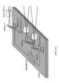
- FIG. 1 is a diagram illustrating an internal configuration example of an in-vehicle camera 100 to which the technology disclosed in this specification is applied.
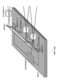
- FIG. 2 is a diagram illustrating a configuration example of a multi-view vehicle-mounted camera 200 to which the technology disclosed in this specification is applied.
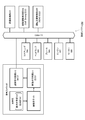
- FIG. 3 is a functional block diagram of the vehicle control system 300.
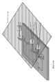
- FIG. 4 is a view showing a modification of the multi-view vehicle-mounted camera 200 shown in FIG.
- FIG. 5 is a diagram illustrating a configuration example in which a reflecting unit is integrally installed near the output end of the condensing optical unit.
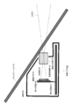
- FIG. 6 is a diagram showing a state where the in-vehicle camera 200 is fixed inside the windshield.
- FIG. 7 is a diagram illustrating an internal configuration example of the in-vehicle camera 700.
- FIG. 8 is a diagram illustrating an internal configuration example of the in-vehicle camera 800.
- FIG. 7 shows an internal configuration example of the in-vehicle camera 700.
- a cross-sectional view of an in-vehicle camera 700 attached to the inside of a windshield 710 of a vehicle, cut along a plane including a horizontal direction (or an optical axis direction of the in-vehicle camera 700 or a traveling direction of the vehicle) and a vertical direction. Is shown.
- the in-vehicle camera 700 includes a first substrate 702 on which an imaging element 701 such as a CCD (Charge Coupled Device) or CMOS (Complementary Metal Oxide Semiconductor) is mounted, and light incident on the windshield 710 from the front of the vehicle (not shown) ( That is, an imaging optical unit 703 that forms an image of a front scene) on the imaging surface of the imaging element 701, and a second substrate 704 separated from the first substrate 702, the first substrate 702 and the second substrate 702 are provided.
- the substrates 704 are electrically connected via the substrate connection portion 705.
- the image sensor 701 has an optical axis in a direction perpendicular to the first substrate 702.
- the housing 706 is a hollow molded product made of, for example, plastic or magnesium alloy.
- the housing 706 accommodates the above-described components 701 to 705, and the inside of the windshield 710 by support means (not shown in FIG. 7) such as a bracket. (For example, in the vicinity of the room mirror).
- the imaging optical unit 703 includes a plurality of appropriately combined optical lenses made of glass or plastic, and a lens barrel that supports these optical lenses.
- the second substrate 704 is mounted with various circuit components for processing a driving circuit of the image sensor 701 and a pixel signal output from the image sensor 701. Specifically, the image picked up by the image sensor 701 is subjected to processing such as image correction and image quality assurance, and image recognition is performed to recognize road white lines (lanes), traffic lights, road signs, oncoming vehicles, and surroundings of the host vehicle. Circuit components for detecting a pedestrian or the like are mounted on the second substrate 704. Based on these detection results, driving support and visibility support can be performed. In addition, when the in-vehicle camera 700 performs mutual communication with a vehicle control system (not shown) using an in-vehicle network such as CAN (Controller Area Network) communication, circuit components for this type of communication processing are also provided. Mounted on the second substrate 704. In other words, the power supply circuit of the in-vehicle camera 700 is also mounted on the second substrate 704.
- CAN Controller Area Network
- the board connecting unit 705 includes an FPC (Flexible Printed Circuit: flexible printed circuit board) and the like, and is connected to each of the boards 702 and 704 via a BtoB (Board to Board) board or the like. .
- FPC Flexible Printed Circuit: flexible printed circuit board
- BtoB Board to Board
- the front scene is incident on the windshield 710 in a substantially horizontal direction.
- the first substrate 702 on which the image sensor 701 is mounted needs to be arranged in a substantially vertical direction as shown in FIG.
- the drive circuit, the image processing circuit, and the power supply circuit of the image sensor 701 are mounted on the first substrate 702, the area is inevitably increased. If the area of the first substrate 702 arranged in a substantially vertical direction is large, the front view of a driver (not shown) is obstructed.
- the driving circuit, the image processing circuit, the communication processing circuit, and the power supply circuit of the image sensor 701 are mounted on the second substrate 704 that is separated from the first substrate 702.
- the area of 702 is made as small as possible, and the second substrate 704 is arranged in a substantially horizontal direction.
- FIG. 8 shows another example of the internal configuration of the in-vehicle camera 800.
- the in-vehicle camera 800 includes a substrate 802 on which circuit components such as an image sensor 801 are mounted, a reflection unit 803 including an optical mirror, and an imaging optical unit 804.
- the image sensor 801 has an optical axis in a direction perpendicular to the substrate 802.
- the housing 805 is a hollow molded product made of, for example, plastic or magnesium alloy.
- the housing 805 accommodates the above-described components 801 to 804, and the inside of the windshield 810 by a support means (not shown in FIG. 8) such as a bracket. (For example, in the vicinity of the room mirror).
- the substrate 802 is mounted with a driving circuit, an image processing circuit, and a power supply circuit (mounted on the second substrate 704 in the example shown in FIG. 7) together with the image sensor 801.
- a driving circuit mounted on the second substrate 704 in the example shown in FIG. 7
- a power supply circuit mounted on the second substrate 704 in the example shown in FIG. 7
- circuit components for this type of communication processing are also mounted on the substrate 802. Is done.
- the in-vehicle camera 800 does not include another substrate separated from the substrate 802.
- the reflection unit 803 reflects (or deflects) light incident on the windshield 710 from the front of the vehicle (not shown) (that is, a front scene) in the direction of the image sensor 801.
- the imaging optical unit 804 images the reflected light from the reflecting unit 803 on the imaging surface of the imaging element 801.
- the imaging optical unit 804 includes a plurality of appropriately combined optical lenses made of glass or plastic, and a lens barrel that supports these optical lenses.
- incident light (a front scene) incident on the windshield 810 in a substantially horizontal direction is reflected (or deflected) by the reflecting unit 803. Therefore, in order to suitably receive an image formed by the imaging optical unit 804, the substrate 802 on which the imaging element 801 is mounted needs to be arranged in a direction substantially perpendicular to the reflection direction by the reflection unit 803. Alternatively, it is not absolutely necessary to arrange the light shield 810 in a direction substantially perpendicular to the light incident direction on the windshield 810.
- the area of the substrate 802 inevitably increases as a result of mounting the image sensor 801 and its drive circuit, image processing circuit, and power supply circuit on the same substrate 802.
- the light axis direction of the image sensor 801 can be deflected in a desired direction by reflecting the incident light to the windshield 810 with the reflecting portion 803, even if the area of the substrate 802 increases, the substrate By disposing 802 from the vertical direction, the forward view of a driver (not shown) can be prevented as much as possible.
- the viewing angle of the image sensor 801 is the viewing angle of the optical mirror that constitutes the reflecting unit 803. It will be limited to.
- the optical mirror In order to increase the viewing angle of the image sensor 801, it is necessary to make the optical mirror larger or use a curved mirror such as a convex mirror. The former increases the size of the device, and the latter increases the size of the mirror and manufactures the device. Assembling becomes difficult.
- the imaging optical unit 804 includes a plurality of optical lenses appropriately combined and a lens barrel that supports these optical lenses (described above).
- the size of the lens (lens barrel) is light. Longer in the axial direction. For this reason, the vehicle-mounted camera 800 for far-field imaging has a concern that the height from the substrate 802 to the reflecting portion 803 becomes large and obstructs the forward field of view of a driver (not shown).
- a multi-view vehicle-mounted camera is configured by combining a plurality of imaging elements having different applications (or focal lengths) such as for far-field imaging, medium-range imaging, and short-distance wide-angle imaging, each coupling optical unit Since the sizes in the optical axis direction vary, the distance (height) from the substrate to each reflecting portion is not uniform, and the assembly becomes troublesome.
- FIG. 1 shows an internal configuration example of an in-vehicle camera 100 to which the technology disclosed in this specification is applied.
- the in-vehicle camera 100 includes a substrate 102 on which circuit components such as an image sensor (CCD, CMOS sensor, etc.) 101 are mounted, a condensing optical unit 103, and a reflecting unit 104.
- the image sensor 101 has an optical axis in a direction perpendicular to the substrate 102.
- the housing 105 is a hollow molded product made of, for example, plastic or magnesium alloy.
- the housing 105 accommodates the above-described components 101 to 104, and the inside of the windshield 110 (for example, a rearview mirror) by the support means 106 such as a bracket. It is fixed in the vicinity.
- the support means 106 may be integrated with support means for attaching the rearview mirror to the inside of the windshield 110. With such a configuration, the number of parts can be reduced as compared with the case where the support means 106 for supporting the in-vehicle camera 100 and the support means for attaching the windshield 110 are provided separately.
- the support means 106 for supporting the in-vehicle camera 100 and the support means for attaching the windshield 110 are provided separately, it is desirable to arrange the support means 106 on the side facing the driver's seat with respect to the rearview mirror.
- the support means 106 is disposed on the right side of the rearview mirror, so that the in-vehicle camera 100 is disposed behind the rearview mirror with respect to the position of the driver's eyes. Thereby, it can suppress that the vehicle-mounted camera 100 obstruct
- the in-vehicle camera 100 is desirably arranged so that the position of the optical axis is an area that is swept with a wiper. This makes it possible to capture the front reliably (that is, with a clear image) with the in-vehicle camera 100 even in rainy weather.
- the board 102 is a printed board on which a wiring pattern is formed, and may be a multilayer board.
- a driver circuit, an image processing circuit, and a power supply circuit are mounted on the substrate 102 together with the image sensor 101.
- circuit components for this type of communication processing are also mounted on the substrate 102. Is done.
- the in-vehicle camera 100 does not include another substrate separated from the substrate 102.
- electrical connection is achieved between the image sensor 101 and a drive circuit, an image processing circuit, a power supply circuit, and the like via a wiring pattern formed on the substrate 102. Therefore, since there is no separate substrate, there is no need for connecting means such as FPC for connecting substrates by FPC.
- the condensing optical unit 103 condenses light that enters the windshield 110 from the front of the vehicle (that is, a front scene). Although simplified in FIG. 1, the condensing optical unit 103 includes a plurality of appropriately combined optical lenses made of glass or plastic, and a lens barrel that supports these optical lenses.
- the reflection unit 104 reflects (or deflects) the output light from the condensing optical unit 103 toward the imaging surface of the imaging element 101 on the substrate 102.
- the reflection unit 104 includes an optical mirror. Basically, a planar optical mirror can be used, but a curved optical mirror such as a convex mirror may be used.
- incident light (a front scene) incident on the windshield 110 in a substantially horizontal direction is first condensed by the condensing optical unit 103 and then reflected by the reflecting unit 104. Reflected (or deflected) on the imaging surface of the imaging element 101. That is, the light emitted from the condensing optical unit 103 is deflected by the reflecting unit 104, so that an image can be directly formed on the imaging surface of the imaging device 101 mounted on the substrate 102.
- the reflecting unit 104 needs to be disposed on the optical axis of the condensing optical unit 103. There is no need to arrange the mounting 102 in a substantially vertical direction with respect to the horizontal direction (or the light incident direction to the windshield 110).
- the area of the substrate 102 is inevitably obtained as a result of mounting the drive circuit, the image processing circuit, and the power supply circuit (not shown) together with the image sensor 101 on the same substrate 102. Will increase.
- the incident light to the windshield 110 is first condensed by the condensing optical unit 103 and then reflected by the reflecting unit 104, whereby the optical axis direction of the image sensor 101 can be deflected in a desired direction.
- the front view of a driver (not shown) can be prevented as much as possible by arranging the board
- the “horizontal direction” here is almost the same direction as the driver's line of sight.
- the “substantially horizontal direction” means that the inclination angle of the plane formed by the substrate 102 with respect to the horizontal direction (or the inclination angle with respect to the vertical direction of the normal line of the plane formed by the substrate 102) is less than a predetermined angle. Yes.
- the “horizontal direction” should be interpreted as “a direction parallel to the ground contact surface of the vehicle”.
- the viewing angle of the imaging element 101 is substantially the same as the viewing angle of the condensing optical unit 103.
- the viewing angle of the optical mirror constituting the reflection unit 104 is not limited. Therefore, it is not necessary to enlarge the optical mirror or use a curved mirror such as a convex mirror in order to secure the viewing angle of the image pickup device 101, and it is possible to avoid an increase in the size of the apparatus and a complicated manufacturing / assembling work. it can.
- the condensing optical unit 103 includes a plurality of optical lenses appropriately combined and a lens barrel that supports these optical lenses (described above), and is used for far-distance imaging, middle-distance imaging, and short-distance wide-angle imaging.
- the size in the direction of the optical axis varies for each time (or depending on the focal length), the configuration after the reflection unit 103 may be substantially the same. Even if the size of the lens (lens barrel) becomes longer in the optical axis direction when trying to capture a distant place, the optical axis direction is almost parallel to the line-of-sight direction of the driver (not shown) and does not obstruct the front field of view so much. That's it.
- a condensing optical unit having a long focal length and a narrow angle of view (about 25 degrees).
- detecting an object existing at an intermediate distance it is only necessary to pick up an image using a condensing optical unit having a shorter focal length and a slightly wider angle of view (about 50 degrees) than that for distant objects.
- a condensing optical unit with a short focal length and a wide angle of view (about 150 degrees) is used. What is necessary is just to image.
- a stereo camera can also be configured by combining image sensors that are arranged so that the parallax is different, although the focal length does not change.
- FIG. 2 shows a configuration example of a multi-view type in-vehicle camera 200 to which the technology disclosed in this specification is applied.
- N image sensors CCD, CMOS sensor, etc.
- CMOS sensor CMOS sensor
- N an integer of 2 or more
- an image processing circuit 203 that processes image signals from 201, 201-2,..., 201 -N, and a driving circuit and a power supply circuit for an image sensor (not shown) are mounted.
- These components are accommodated in a housing (not shown).
- the vehicle-mounted camera 200 is supported by the bracket which is not illustrated inside the windshield 210, as shown in FIG.
- Condensing optical units 204-1, 204-2,... For condensing light incident on the windshield 110 (that is, a front scene) for each of the image sensors 201-1, 201-2,. 204-N and the output light from each of the condensing optical sections 204-1, 204-2,..., 204-N are respectively applied to the imaging surfaces of the corresponding image sensors 201-1 201-2,. Reflecting portions 205-1, 205-2,..., 205-N that are reflective (or deflected) toward the screen are disposed. Similar to the monocular in-vehicle camera 100 shown in FIG.
- a plurality of image sensors can be obtained by using a configuration in which the light emitted from the condensing optical unit is deflected by the reflecting unit and directly imaged on the imaging surface. It should be fully understood that even the vehicle-mounted camera 200 on which 201-1, 201-2,...
- Each of the image sensors 201-1, 201-2,..., 201-N and the image processing circuit 203 can obtain stable EMC characteristics by wiring at the shortest distance by the wiring pattern formed on the substrate 202. .
- the EMC characteristics are improved and the number of parts is reduced. The effect of improving productivity is extremely large.
- the above-mentioned parts 201 are accommodated in a casing (not shown) and are fixed to the inside of the windshield of the vehicle (for example, in the vicinity of the room mirror) by support means such as a bracket.
- Each of the condensing optical units 204-1, 204-2,..., 204-N includes a plurality of optical lenses that are appropriately combined according to each application, and a lens barrel that supports these optical lenses.
- Each of the reflection units 205-1 205-2,..., 205-N includes an optical mirror. Basically, a planar optical mirror can be used. .., 204-N may have different sizes and diameters depending on the application. The size and diameter in the optical axis direction increase in accordance with the distance to the subject to be captured by each of the image sensors 201-1, 201-2, ..., 201-N.
- each of the reflection units 205-1, 205-2,..., 205-N has almost the same configuration. In FIG. 2, the reflection units 205-1 205-2,..., 205-N divided for each of the image sensors 201-1, 201-2,..., 201-N are used. As shown in FIG. 4, an integrated reflecting portion 205 may be attached on the substrate 202.
- each of the reflection units 205-1, 205-2,..., 205 -N is mounted on the substrate 202 in the vicinity of the corresponding image pickup devices 201-1, 201-2,. I imagine that. Of course, as shown in FIG. 5, not on the substrate 202 side, but near the output ends of the corresponding condensing optical units 204-1, 204-2,. , 205-N can be considered as a modification.
- FIG. 2 shows an example in which a plurality of image sensors 201-1... Are arranged in a line on the substrate 202, but a plurality of image sensors are arranged in a two-dimensional array or a plurality of image sensors.
- a configuration example of a multi-view vehicle-mounted camera in which elements are arranged irregularly is also conceivable.
- FIG. 3 shows an example of a functional block diagram of the vehicle control system 300.
- the illustrated control system 300 includes the in-vehicle camera 100 illustrated in FIG. 1, and each unit is interconnected via a CAN bus.
- the in-vehicle camera 100 is disposed, for example, in the vicinity of a room mirror inside the windshield of the vehicle, and images the front in the vehicle traveling direction.
- the captured image of the in-vehicle camera 100 is basically used for sensing purposes, and image processing such as image recognition is applied to the captured image, and a road white line (lane), traffic light, road sign, oncoming vehicle, own vehicle It is assumed that surrounding pedestrians are detected.
- the captured image of the in-vehicle camera 100 may also be used for viewing purposes and displayed in the passenger compartment.
- the in-vehicle camera 100 includes an optical system including the condensing optical unit 103 and the reflecting unit 104, an image sensor 101, an image processing circuit 311, and a communication processing circuit 312.
- the condensing optical unit 103 condenses the incident light to the windshield 110, and the reflecting unit 104 reflects the output light from the condensing optical unit 103 toward the imaging surface of the image sensor 101 (described above).
- the reflection unit 104, the image sensor 101, the image processing circuit 311 and the communication processing circuit 312 are mounted on the same substrate 102 (not shown in FIG. 3). Although not shown in FIG. 3, it is assumed that the drive circuit for the image sensor 101 and the power supply circuit for the in-vehicle camera 100 are also mounted on the same substrate.
- the image sensor 101 outputs a captured image (RAW data) to the image processing circuit 311 by serial communication, for example.
- the imaging element 101 and the image processing circuit 311 are wired at the shortest distance by a wiring pattern formed on the substrate 102, and stable EMC characteristics can be obtained.
- the image processing circuit 311 is configured by, for example, an ECU (Electronic Control Unit). In the case of the in-vehicle camera 100 for sensing purposes, image processing and recognition processing are performed on an image captured by the image sensor 101 in the image processing circuit 311.
- ECU Electronic Control Unit
- Image processing performed in the image processing circuit 311 includes processing such as AE (Automatic Exposure: automatic exposure control), AWB (Auto White Balance: automatic white balance adjustment), HDR (High Dynamic Range: high dynamic range composition), and the like. Can be mentioned. However, these image processes can also be performed on the image sensor 101 side.
- white line (lane) detection (lane detection), pedestrian detection (pedestrian detection), detection of surrounding vehicles (vehicle detection), headlights that turn on the oncoming vehicle Detection (Headlight Detection), detection of lighting of the brake light of the preceding vehicle (Automatic Emergency Breaking), traffic signal recognition (Traffic Sign Recognition), and the like.
- the communication processing circuit 312 is configured by, for example, an MCU (Micro Control Unit).
- the communication processing circuit 312 is an interface with CAN communication in the control system 300, and performs format conversion between a signal format in CAN communication and a signal format in the in-vehicle camera 100.
- Each detection / recognition result by the image processing circuit 311 is sent to the vehicle control system 300 via the communication processing circuit 312.
- a communication processing unit 301 on the vehicle control system 300 side is responsible for data transmission / reception in vehicle-to-vehicle communication, vehicle-to-vehicle communication, road-to-vehicle communication, and communication with the in-vehicle camera 100.
- the communication processing unit 301 further exchanges with a server (not shown). It is assumed that the communication processing unit 301 can apply various types of wireless communication.
- An automatic driving control unit (Self Driving ECU) 302 is an ECU including a CPU (Central Processing Unit), an ISP (Image Signal Processor), a GPU (Graphic Processing Unit), and the like, and controls automatic driving of the vehicle.
- the result of image recognition of the image captured by the in-vehicle camera 100 by the GPU can be sent to the server via the communication processing unit 301, and the learning result can be received by executing deep learning by a server such as a deep neural network. .
- a driving support control unit (ADAS (Advanced Driving Assistance System) ECU) 303 can transmit and receive signals to and from each component of the vehicle via CAN communication.
- the driving support control unit 303 generates a control signal for controlling each component of the vehicle according to the driving operation of the driver, the recognition result of the captured image by the in-vehicle camera 100, and the like, and sends it through CAN communication.
- Steering 304, headlamp 305, brake 306, engine 307, and motor 308 are components of a vehicle that are controlled by the automatic driving control unit 302 and the driving support control unit 303. However, it should be understood that there are components of the vehicle that can be controlled in addition to those shown in FIG.
- the driving support control unit 303 detects that the host vehicle is about to deviate from the white line by recognizing the captured image of the in-vehicle camera 100, the driving support control unit 303 performs EPS (Electronic Power Steering: electronic power A control signal for driving the steering motor is sent.
- EPS Electronic Power Steering: electronic power
- the driving support control unit 303 detects the presence or absence of the headlight of the oncoming vehicle based on the image recognition of the captured image of the in-vehicle camera 100, and switches between the high beam and the low beam of the headlamp 305.
- a high beam that avoids oncoming vehicles is irradiated.
- the image processing circuit 311 in the in-vehicle camera 100 may output only the recognized sensing information, that is, the detection result by the image recognition, instead of outputting the image information itself as the recognition process. Some sensing information is illustrated below.
- FCW Forward Collation Warning
- AEB Automatic Emergency Breaking
- LDW Vehicle Detection for FCW / AEB -Lane Departure Warning
- TJP -Traffic Jam Pilot
- the vehicle speed controls the vehicle speed according to the presence or absence of the preceding vehicle, recognizes the road sign related to the speed limit, controls the vehicle speed, recognizes the road sign at the entrance and exit of the highway, and controls the vehicle speed, When the vehicle approaches a curve, it automatically decelerates.
- LKA -Lane Keeping Aid
- VOACC Vision Only Adaptive Cruise Control
- VTSR Vision Only Traffic Sign Recognition
- Intelligent Head Ramp Control Detects the presence or absence of headlights in the oncoming vehicle and switches between the high beam and low beam of the headlamp of the host vehicle. Further, the presence or absence of the tail lamp of the preceding vehicle is detected, and the high beam and the low beam of the head lamp of the own vehicle are switched. Further, it is determined whether the light source is in the left or right lane, and a high beam is emitted so as to avoid oncoming vehicles and preceding vehicles.
- the on-vehicle camera to which the technology disclosed in the present specification is applied has been mainly described in the embodiment installed on the windshield of the vehicle.
- the gist of the technology disclosed in the present specification is limited to this. It is not a thing.
- the technique disclosed in the present specification can be similarly applied to an in-vehicle camera installed in a place other than the windshield.
- the technology disclosed in this specification can be applied not only to a vehicle-mounted camera but also to a camera mounted on various mobile devices such as a ship, an aircraft, and a mobile robot.
- the technology disclosed in the present specification can also be configured as follows.
- a substrate An image sensor mounted on the substrate; An image processing circuit mounted on the substrate and processing an image captured by the image sensor; A condensing optical unit that condenses incident light; A reflection unit that reflects the output light from the condensing optical unit to the imaging device; In-vehicle camera equipped with.
- the apparatus further includes a housing that houses at least the imaging device and the image processing circuit, the condensing optical unit, and the reflecting unit.
- the vehicle-mounted camera as described in said (1).
- the casing is fixed to the inside of the windshield of the vehicle via a bracket.
- the vehicle-mounted camera as described in said (1) It further includes a communication processing circuit mounted on the substrate for transmitting and receiving data.
- the image pickup device further includes a drive circuit mounted on the substrate.
- the vehicle-mounted camera as described in said (1). further comprising a power supply circuit mounted on the substrate;
- the vehicle-mounted camera as described in said (1). A plurality of image sensors are mounted on the substrate, A plurality of condensing optical units corresponding to each of the plurality of image sensors, and a reflecting unit that reflects output light from each condensing optical unit toward the corresponding image sensor, The vehicle-mounted camera as described in said (1).
- the reflection unit includes a plurality of mirrors respectively corresponding to the plurality of condensing optical units.
- the condensing optical part and the reflecting part are integrally formed.
- the image processing circuit performs image processing and recognition processing on an image captured by the image sensor.
- the image processing circuit performs at least one of automatic exposure control, automatic white balance adjustment, or high dynamic range synthesis of the image sensor as the image processing.
- the vehicle-mounted camera as described in said (11).
- the image processing circuit may perform road lane detection, pedestrian detection, detection of surrounding vehicles, detection of headlights that turn on an oncoming vehicle, detection of lighting of a brake light of a preceding vehicle, signal recognition, as the recognition processing. At least one of them, The vehicle-mounted camera as described in said (11). (14) Externally outputting information of a detection result obtained by the recognition processing in the image processing circuit. The vehicle-mounted camera as described in said (11).
- an image sensor mounted on the substrate An image processing circuit mounted on the substrate and processing an image captured by the image sensor; A condensing optical unit that condenses incident light; A reflection unit that reflects the output light from the condensing optical unit to the imaging device; A housing for housing the substrate; A bracket for fixing the housing to the inside of the windshield of the vehicle; An in-vehicle camera device comprising: (16) The bracket supports the housing so that the substrate housed in the housing is in a substantially horizontal direction.
- the in-vehicle camera device according to (15) above.
- a method for supporting an in-vehicle camera wherein the casing of the in-vehicle camera according to (1) is supported by a bracket and is fixed inside a windshield of the vehicle.
- DESCRIPTION OF SYMBOLS 100 ... Car-mounted camera, 101 ... Image pick-up element, 102 ... Board
- Driving support controller 304 Steering 305 ... Headlamp 306 ... Brake 307 ... Engine 308 ... Motor 311 ... Image processing circuit, 312 ... Communication processing circuit 700 ... In-vehicle camera 701 ... Image sensor, 702 ... First substrate 703 DESCRIPTION OF SYMBOLS Image forming optical part, 704 ... 2nd board
Landscapes
- Physics & Mathematics (AREA)
- General Physics & Mathematics (AREA)
- Engineering & Computer Science (AREA)
- Multimedia (AREA)
- Signal Processing (AREA)
- Mechanical Engineering (AREA)
- Optics & Photonics (AREA)
- Studio Devices (AREA)
- Fittings On The Vehicle Exterior For Carrying Loads, And Devices For Holding Or Mounting Articles (AREA)
- Lens Barrels (AREA)
- Cameras In General (AREA)
- Camera Bodies And Camera Details Or Accessories (AREA)
- Accessories Of Cameras (AREA)
Abstract
車両のウインドシールドなどに取り付けて用いられる優れた車載カメラ、車載用カメラ装置、並びに車載カメラの支持方法を提供する。 車載カメラは、基板と、前記基板上に実装された撮像素子と、前記基板上に実装され、前記撮像素子による撮像画像を処理する画像処理回路と、入射光を集光する集光光学部と、前記集光光学部からの出力光を前記撮像素子へ反射させる反射部を具備する。車載カメラは、少なくとも前記撮像素子及び前記画像処理回路が実装された前記基板と、前記集光光学部と、前記反射部を収容する筐体をさらに備えている。
Description
本明細書で開示する技術は、車両のウインドシールドなどに取り付けて用いられる車載カメラ、車載用カメラ装置、並びに車載カメラの支持方法に関する。
最近、カメラを搭載する自動車が増えてきている(例えば、特許文献1、2を参照のこと)。車載カメラが撮影した画像を、例えば車室内のモニター画面でドライバーやその他の搭乗者に見せたり、ドライブ・レコーダーに記録したりすることができる。また、車載カメラが撮影した画像に対して画像認識などの画像処理を適用して、道路の白線(レーン)や信号機、道路標識、対向車、自車両周辺の歩行者などを検出した結果に基づいて走行支援や視界支援を行なったりすることができる。
本明細書で開示する技術の目的は、車両のウインドシールドなどに取り付けて用いられる優れた車載カメラ、車載用カメラ装置、並びに車載カメラの支持方法を提供することにある。
本明細書で開示する技術の第1の側面は、
基板と、
前記基板上に実装された撮像素子と、
前記基板上に実装され、前記撮像素子による撮像画像を処理する画像処理回路と、
入射光を集光する集光光学部と、
前記集光光学部からの出力光を前記撮像素子へ反射させる反射部と、
を具備する車載カメラ。
基板と、
前記基板上に実装された撮像素子と、
前記基板上に実装され、前記撮像素子による撮像画像を処理する画像処理回路と、
入射光を集光する集光光学部と、
前記集光光学部からの出力光を前記撮像素子へ反射させる反射部と、
を具備する車載カメラ。
本明細書で開示する技術の第2の側面によれば、第1の側面に係る車載カメラは、少なくとも前記撮像素子及び前記画像処理回路が実装された前記基板と、前記集光光学部と、前記反射部を収容する筐体をさらに備えている。
本明細書で開示する技術の第3の側面によれば、第2の側面に係る車載カメラの前記筐体は、ブラケットを介して車両のウインドシールドの内側に固定されている。
本明細書で開示する技術の第4の側面によれば、第1の側面に係る車載カメラは、前記基板がほぼ水平方向となるように、車両のウインドシールドの内側に固定されている。
本明細書で開示する技術の第5の側面によれば、第1の側面に係る車載カメラは、前記基板上に実装された、データ送受信を行なう通信処理回路をさらに備えている。
本明細書で開示する技術の第6の側面によれば、第1の側面に係る車載カメラは、前記基板上に実装された、前記撮像素子の駆動回路をさらに備えている。
本明細書で開示する技術の第7の側面によれば、第1の側面に係る車載カメラは、前記基板上に実装された電源回路をさらに備えている。
本明細書で開示する技術の第8の側面によれば、第1の側面に係る車載カメラは、前記基板上に複数の撮像素子が実装され、前記複数の撮像素子の各々に対応する複数の集光光学部と、各集光光学部からの出力光をそれぞれに対応する撮像素子に向けて反射させる反射部を備えている。
本明細書で開示する技術の第9の側面によれば、第8の側面に係る車載カメラの前記反射部は、前記複数の集光光学部にそれぞれ対応する複数のミラーで構成されている。
本明細書で開示する技術の第9の側面によれば、第1の側面に係る車載カメラの前記集光光学部と前記反射部は一体的に形成されている。
本明細書で開示する技術の第11の側面によれば、第1の側面に係る車載カメラの前記画像処理回路は、前記撮像素子による撮像画像に対して画像処理及び認識処理を実施するように構成されている。
本明細書で開示する技術の第12の側面によれば、第11の側面に係る車載カメラの前記画像処理回路は、前記画像処理として、前記撮像素子の自動露出制御、自動ホワイト・バランス調整、又は、ハイダイナミックレンジ合成のうち少なくとも1つを実施するように構成されている。
本明細書で開示する技術の第13の側面によれば、第11の側面に係る車載カメラの前記画像処理回路は、前記認識処理として、道路のレーン検出、歩行者検出、周辺車両の検出、対向車両が点灯するヘッドライトの検出、先行車両のブレーキライトの点灯検出、信号機認識のうち少なくとも1つを実施するように構成されている。
本明細書で開示する技術の第14の側面によれば、第11の側面に係る車載カメラは、前記画像処理回路における前記認識処理により得られた検出結果の情報を外部出力するように構成されている。
また、本明細書で開示する技術の第15の側面は、
前記基板上に実装された撮像素子と、
前記基板上に実装され、前記撮像素子による撮像画像を処理する画像処理回路と、
入射光を集光する集光光学部と、
前記集光光学部からの出力光を前記撮像素子へ反射させる反射部と、
前記基板を収容する筐体と、
前記筐体を車両のウインドシールドの内側に固定するブラケットと、
を具備する車載カメラ装置である。
前記基板上に実装された撮像素子と、
前記基板上に実装され、前記撮像素子による撮像画像を処理する画像処理回路と、
入射光を集光する集光光学部と、
前記集光光学部からの出力光を前記撮像素子へ反射させる反射部と、
前記基板を収容する筐体と、
前記筐体を車両のウインドシールドの内側に固定するブラケットと、
を具備する車載カメラ装置である。
本明細書で開示する技術の第16の側面によれば、第15の側面に係る車載カメラ装置の前記ブラケットは、前記筐体に収容された前記基板がほぼ水平方向となるように前記筐体を支持するように構成されている。
また、本明細書で開示する技術の第17の側面は、第1の側面に係る車載カメラの筐体をブラケットで支持して、車両のウインドシールドの内側に固定する、車載カメラの支持方法である。
本明細書で開示する技術によれば、車両のウインドシールドなどに取り付けて用いられる優れた車載カメラ、車載用カメラ装置、並びに車載カメラの支持方法を提供することができる。
なお、本明細書に記載された効果は、あくまでも例示であり、本発明の効果はこれに限定されるものではない。また、本発明が、上記の効果以外に、さらに付加的な効果を奏する場合もある。
本明細書で開示する技術のさらに他の目的、特徴や利点は、後述する実施形態や添付する図面に基づくより詳細な説明によって明らかになるであろう。
以下、図面を参照しながら本明細書で開示する技術の実施形態について詳細に説明する。
図7には、車載カメラ700の内部構成例を示している。同図では、車両のウインドシールド710の内側に取り付けた状態の車載カメラ700を、水平方向(若しくは、車載カメラ700の光軸方向又は車両の進行方向)と垂直方向を含む平面で切断した断面図で示している。
車載カメラ700は、CCD(Charge Coupled Device)やCMOS(Complementary Metal Oxide Semiconductor)などの撮像素子701を実装する第1の基板702と、車両(図示しない)の前方からウインドシールド710に入射する光(すなわち、前方の光景)を撮像素子701の撮像面上に結像させる結像光学部703と、第1の基板702から分離した第2の基板704を備え、第1の基板702と第2の基板704間は基板接続部705を介して電気的に接続されている。撮像素子701は、第1の基板702に対して垂直方向に光軸を持つものとする。
筐体706は、例えばプラスチックやマグネシウム合金などからなる中空の成形品であり、上記の部品701~705を収容するとともに、ブラケットなどの支持手段(図7では図示しない)によって、ウインドシールド710の内側(例えば、ルーム・ミラーの近傍)に固定されている。
図7では簡略化して描いているが、結像光学部703は、ガラス又はプラスチックからなる、適正に組み合わされた複数の光学レンズと、これら光学レンズを支持するレンズ鏡筒からなる。
第2の基板704は、撮像素子701の駆動回路や、撮像素子701から出力される画素信号を処理するための各種回路コンポーネントを実装している。具体的には、撮像素子701による撮像画像に対して画像補正や画質保証などの処理を行なう他、画像認識を実施して道路の白線(レーン)や信号機、道路標識、対向車、自車両周辺の歩行者などを検出するための回路コンポーネントが、第2の基板704上に実装される。これらの検出結果に基づいて走行支援や視界支援を行なうことができる。また、車載カメラ700がCAN(Controller Area Network)通信などの車載ネットワークを利用して車両自体の制御システム(図示しない)と相互通信を行なう場合には、この種の通信処理のための回路コンポーネントも第2の基板704上に実装される。付言すれば、車載カメラ700の電源回路も、第2の基板704上に実装される。
また、基板接続部705は、FPC(Flexible Printed Circuit:フレキシブル・プリント回路基板)などからなり、BtoB(Board to Board:基板対基板接続)コネクターなどを介して各基板702、704にそれぞれ接続される。
前方の光景は、ほぼ水平方向にウインドシールド710に入射する。この入射光の結像光学部703による像を好適に受光するために、撮像素子701を実装する第1の基板702は図7に示したようにほぼ垂直方向に配置する必要がある。ここで、撮像素子701の駆動回路や画像処理回路、電源回路まで第1の基板702上に実装してしまうと必然的に面積が増大する。ほぼ垂直方向に配置された第1の基板702の面積が大きいと、ドライバー(図示しない)の前方視界を阻害することになる。このため、車載カメラ700では、撮像素子701の駆動回路や画像処理回路、通信処理回路、電源回路を、第1の基板702とは分離した第2の基板704上に実装して第1の基板702の面積をできる限り小さくし、且つ、第2の基板704をほぼ水平方向に配置している訳である。
しかしながら、第1の基板702と第2の基板704を分離した構成にすると、FPCなどの基板接続部705で基板同士を接続する必要があるため、製造工程が増えて生産性が低下することが懸念される。さらに、基板間の電気的な信頼性が低下することや、FPCがEMI(Electro Magnetic Interference:電磁妨害)の発生源になることが懸念される。
図8には、車載カメラ800の他の内部構成例を示している。同図では、車両のウインドシールド810の内側に取り付けた状態の車載カメラ800を、水平方向(若しくは、車載カメラ800の光軸方向又は車両の進行方向)と垂直方向を含む平面で切断した断面図で示している。
車載カメラ800は、撮像素子801などの回路コンポーネントを実装する基板802と、光学ミラーなどからなる反射部803と、結像光学部804を備えている。撮像素子801は、基板802に対して垂直方向に光軸を持つものとする。筐体805は、例えばプラスチックやマグネシウム合金などからなる中空の成形品であり、上記の部品801~804を収容するとともに、ブラケットなどの支持手段(図8では図示しない)によって、ウインドシールド810の内側(例えば、ルーム・ミラーの近傍)に固定されている。
図8に示す例では、基板802は、撮像素子801とともに、(図7に示した例では第2の基板704上に実装される)駆動回路や画像処理回路、電源回路も実装している。また、車載カメラ800がCAN通信などの車載ネットワークを利用して車両自体の制御システム(図示しない)と相互通信を行なう場合には、この種の通信処理のための回路コンポーネントも基板802上に実装される。基本的に、車載カメラ800は、基板802とは分離した他の基板を含まないものとする。
反射部803は、車両(図示しない)の前方からウインドシールド710に入射する光(すなわち、前方の光景)を撮像素子801の方向に反射(若しくは偏向)させる。
結像光学部804は、反射部803による反射光を、撮像素子801の撮像面に結像させる。図8では簡略化して描いているが、結像光学部804は、ガラス又はプラスチックからなる、適正に組み合わされた複数の光学レンズと、これら光学レンズを支持するレンズ鏡筒からなる。
図8に示す車載カメラ800の構成例によれば、ほぼ水平方向にウインドシールド810に入射する入射光(前方の光景)は反射部803によって反射(若しくは偏向)される。したがって、結像光学部804による像を好適に受光するために、撮像素子801を実装する基板802を、反射部803による反射方向に対してほぼ垂直方向に配置する必要があるが、水平方向(若しくは、ウインドシールド810への光の入射方向)に対してほぼ垂直方向に配置する必要はまったくない。
図8に示す車載カメラ800の構成例では、撮像素子801とともに、その駆動回路や画像処理回路、電源回路まで同一の基板802上に実装する結果として、必然的に基板802の面積が増大する。しかしながら、ウインドシールド810への入射光を反射部803で反射させることによって、撮像素子801の光軸方向を所望の方向に偏向することができるので、基板802の面積が大きくなったとしても、基板802を垂直方向から傾けて配置することで、ドライバー(図示しない)の前方視界をなるべく阻害しないようにすることができる。
また、基板802の実装面積の増大が許容される結果として、ほとんどすべての回路コンポーネントを単一の基板802上に実装することが可能になる。したがって、分離した別の基板が不要になることから、FPCなどによる基板同士を接続する必要がなくなり、製造工程が簡素化して生産性が向上するとともに、EMIの発生源であるFPCを取り除くことができる。
しかしながら、図8に示すようにウインドシールド810への入射光を最初に反射部803で反射(若しくは偏向)するという構成では、撮像素子801の視野角が反射部803を構成する光学ミラーの視野角に制限されてしまう。撮像素子801の視野角を大きくするには、光学ミラーをより大きくするか、凸面鏡などの曲面ミラーを用いる必要があり、前者では装置サイズが増大してしまい、後者ではミラーの製作や装置への組み立てが難しくなる。
また、結像光学部804は、適正に組み合わされた複数の光学レンズとこれら光学レンズを支持するレンズ鏡筒からなるが(前述)、遠方を捉えようとするとレンズ(鏡筒)のサイズは光軸方向に長くなる。このため、遠方撮像用の車載カメラ800は、基板802から反射部803までの高さが大きくなってしまい、ドライバー(図示しない)の前方視界を阻害することが懸念される。また、遠方撮像用、中距離撮像用、近距離広角撮像用といった、用途(若しくは、焦点距離)が異なる複数の撮像素子を組み合わせて多眼式の車載カメラを構成する場合、各々の結合光学部の光軸方向のサイズがまちまちであるため、基板から各々の反射部までの距離(高さ)が均一でなく、組み立てが面倒になる。
図1には、本明細書で開示する技術を適用した車載カメラ100の内部構成例を示している。同図では、車両のウインドシールド110の内側に取り付けた状態の車載カメラ100を、水平方向(若しくは、車載カメラ100の光軸方向又は車両の進行方向)と垂直方向を含む平面で切断した断面図で示している。
車載カメラ100は、撮像素子(CCDやCMOSセンサーなど)101を始めとする回路コンポーネントを実装する基板102と、集光光学部103と、反射部104を備えている。撮像素子101は、基板102に対して垂直方向に光軸を持つものとする。
筐体105は、例えばプラスチックやマグネシウム合金などからなる中空の成形品であり、上記の部品101~104を収容するとともに、ブラケットなどの支持手段106によって、ウインドシールド110の内側(例えば、ルームミラーの近傍)に固定されている。支持手段106は、ルームミラーをウインドシールド110の内側に取り付けるための支持手段と一体的に構成されていてもよい。このような構成にすることで、車載カメラ100を支持する支持手段106とウインドシールド110を取り付けるための支持手段とを別々に設ける場合と比較して部品点数を削減することができる。さらに、車載カメラ100を支持する支持手段106とウインドシールド110を取り付けるための支持手段を別々に設ける場合、支持手段106をルームミラーに対して運転席と対向する側へ配置することが望ましい。例えば、車両の運転席が左側である場合、支持手段106は、ルームミラー右側に配置することで、車載カメラ100がドライバーの眼の位置に対してルームミラーの背後に配置される。これにより、車載カメラ100がドライバーの視界を遮るのを抑制することができる。さらに、車載カメラ100は、光軸の位置がワイパーで掃かれる領域となるように配置されることが望ましい。これにより、雨天時にも車載カメラ100で確実に(すなわち、鮮明な映像で)前方を撮像することが可能となる。
基板102は、配線パターンが形成されたプリント基板であり、多層基板であってもよい。基板102上には、撮像素子101とともに、駆動回路や画像処理回路、電源回路も実装されている。また、車載カメラ100がCAN通信などの車載ネットワークを利用して車両自体の制御システム(図示しない)と相互通信を行なう場合には、この種の通信処理のための回路コンポーネントも基板102上に実装される。基本的に、車載カメラ100は、基板102とは分離した他の基板を含まないものとする。また、撮像素子101と、駆動回路や画像処理回路、電源回路などの間は基板102に形成されている配線パターンを介して電気接続が果たされる。したがって、分離した別の基板が存在しないことから、FPCなどによる基板同士を接続するFPCなどの接続手段は不要である。
集光光学部103は、車両の前方からウインドシールド110に入射する光(すなわち、前方の光景)を集光する。図1では簡略化して描いているが、集光光学部103は、ガラス又はプラスチックからなる、適正に組み合わされた複数の光学レンズと、これら光学レンズを支持するレンズ鏡筒からなる。
反射部104は、集光光学部103からの出力光を、基板102上の撮像素子101の撮像面に向かって反射(若しくは偏向)させる。反射部104は、光学ミラーからなる。基本的には、平面状の光学ミラーを利用することができるが、凸面鏡など曲面状の光学ミラーを用いてもよい。
図1に示す車載カメラ100の構成例によれば、ほぼ水平方向にウインドシールド110に入射する入射光(前方の光景)は、まず集光光学部103で集光された後、反射部104によって撮像素子101の撮像面に反射(若しくは偏向)される。すなわち、集光光学部103からの出射光を反射部104で偏向することにより、基板102上に実装された撮像素子101の撮像面に直接結像させることができる。このような構成によれば、集光光学部103からの出力光を好適に反射させるために、反射部104を集光光学部103の光軸上に配置する必要があるが、撮像素子101を実装する102を水平方向(若しくは、ウインドシールド110への光の入射方向)に対してほぼ垂直方向に配置する必要はまったくない。
図1に示す車載カメラ100の構成例では、撮像素子101とともに、その駆動回路や画像処理回路、電源回路(図示しない)まで同一の基板102上に実装する結果として、必然的に基板102の面積が増大する。しかしながら、ウインドシールド110への入射光をまず集光光学部103で集光した後、反射部104で反射させることによって、撮像素子101の光軸方向を所望の方向に偏向することができる。このため、基板102の面積が大きくなったとしても、基板102をほぼ水平方向に配置することで、ドライバー(図示しない)の前方視界をなるべく阻害しないようにすることができる。
但し、ここで言う「水平方向」はドライバーの視線方向とほぼ同じ方向であることを想定している。また、「ほぼ水平方向」とは、基板102のなす平面の水平方向に対する傾斜角(若しくは、基板102のなす平面の法線の垂直方向に対する傾斜角)が所定角度未満であることを意味している。なお、車両が坂道など傾斜した路面を走行して車体も傾いているときには、「水平方向」を「車両の接地面と平行な方向」と解釈すべきである。
また、基板102の実装面積の増大が許容される結果として、カメラの機能を実現するために必要なほとんどすべての回路コンポーネントを単一の基板102上に実装することが可能になる。したがって、分離した別の基板が不要になることから、FPCなどによる基板同士を接続する必要がなくなり、製造工程が簡素化して生産性が向上するとともに、EMIの発生源であるFPCを取り除くことができる。同一の基板102上に撮像素子101と画像処理回路チップ(図示しない)を実装し、基板102に形成された配線パターンにより最短距離で配線することにより、安定したEMC(Electro Magnetic Compatibility:電磁両立性)特性を得ることができる。付言すれば、基板やFPCなどの部品数が削減されることによるコストダウンも期待することができる。
また、図1に示すように、ウインドシールド110への入射光をまず集光光学部103で集光するという構成では、撮像素子101の視野角は集光光学部103の視野角とほぼ同じであり、反射部104を構成する光学ミラーの視野角に制限されることはない。したがって、撮像素子101の視野角を確保するために、光学ミラーを大きくしたり凸面鏡などの曲面ミラーを用いたりする必要はなく、装置サイズの増大や製作・組み立て作業の複雑化を回避することができる。
また、集光光学部103は、適正に組み合わされた複数の光学レンズとこれら光学レンズを支持するレンズ鏡筒からなり(前述)、遠方撮像用、中距離撮像用、近距離広角撮像用といった用途毎に(若しくは、焦点距離に応じて)光軸方向のサイズがまちまちになるが、反射部103以降の構成はほぼ同一でよい。遠方を捉えようとするとレンズ(鏡筒)のサイズが光軸方向に長くなったとしても、光軸方向はドライバー(図示しない)の視線方向とほぼ平行であり、前方視界をあまり阻害しなくて済む。また、用途が異なる複数の撮像素子を組み合わせて多眼式の車載カメラを構成する場合であっても、各光学系の先端部分の集光光学部103が変わるだけなので、組み立て作業が煩雑になることはない。
ちなみに、遠方の物体を検出するような高解像度が要求される場合は、焦点距離が長く、(25度程度の)画角が狭い集光光学部を用いて撮像すればよい。また、中距離に存在する物体を検出する場合は、遠方用よりも焦点距離が短く、(50度程度の)画角がやや広い集光光学部を用いて撮像すればよい。また、近距離に存在する物体を検出するような、なるべく広い範囲で物体を検知しなければならない場合は、焦点距離が短く、(150度程度の)画角が広い集光光学部を用いて撮像すればよい。勿論、焦点距離の異なる撮像素子を組み合わせる以外に、焦点距離は変わらないが視差が異なるように配設された撮像素子を組み合わせてステレオカメラを構成することもできる。
図2には、本明細書で開示する技術を適用した、多眼式の車載カメラ200の構成例を示している。
基板202上には、N個の撮像素子(CCDやCMOSセンサーなど)201-1、201-2、…、201-Nと(但し、Nは2以上の整数とする)、各撮像素子201-1、201-2、…、201-Nからの画像信号を処理する画像処理回路203と、図示しない撮像素子の駆動回路や電源回路が実装されている。これらの部品は、図示しない筐体に収容されている。そして、車載カメラ200は、図6に示すように、ウインドシールド210の内側に、図示しないブラケットにより支持されている。
撮像素子201-1、201-2、…、201-N毎に、ウインドシールド110に入射する光(すなわち、前方の光景)を集光する集光光学部204-1、204-2、…、204-Nと、各集光光学部204-1、204-2、…、204-Nからの出力光をそれぞれ対応する撮像素子201-1、201-2、…、201-Nの撮像面に向けて反射(若しくは偏向)する反射部205-1、205-2、…、205-Nが配設されている。図1に示した単眼式の車載カメラ100と同様に、集光光学部からの出射光を反射部で偏向させることにより撮像面に直接結像させるという構成を利用することにより、複数の撮像素子201-1、201-2、…、201-Nが搭載された車載カメラ200であっても単一の基板202のみで機能を実現できる、という点を十分理解されたい。
各撮像素子201-1、201-2、…、201-Nと画像処理回路203は、基板202上に形成された配線パターンにより最短距離で配線することにより、安定したEMC特性を得ることができる。複数の撮像素子を用いた多眼式の車載カメラの場合、各撮像素子を分離した基板に実装してFPCで基板間を接続する製品と比較すると、EMC特性の向上や、部品数の削減による生産性向上の効果は極めて大きい。
上記の部品201…は、図示しない筐体に収容され、ブラケットなどの支持手段によって車両のウインドシールドの内側(例えば、ルーム・ミラーの近傍)に固定されているものとする。
各集光光学部204-1、204-2、…、204-Nは、それぞれの用途に応じて適正に組み合わされた複数の光学レンズと、これら光学レンズを支持するレンズ鏡筒からなる。また、各反射部205-1、205-2、…、205-Nは、光学ミラーからなる。基本的には、平面状の光学ミラーを利用することができる。各集光光学部204-1、204-2、…、204-Nの光軸方向のサイズや径などは用途に応じてまちまちになる可能性がある。各撮像素子201-1、201-2、…、201-Nで捉えたい被写体までの距離に応じて、光軸方向のサイズや径は大きくなる。一方、各反射部205-1、205-2、…、205-Nはほぼ同じ構成である。図2では、撮像素子201-1、201-2、…、201-N毎に分断された反射部205-1、205-2、…、205-Nを用いているが、変形例として、図4に示すように一体化した一枚の反射部205を基板202上に取り付けるようにしてもよい。
図2では、各反射部205-1、205-2、…、205-Nは、基板202上の、それぞれに対応する撮像素子201-1、201-2、…、201-N付近に取り付けられていることをイメージしている。勿論、基板202側でなく、図5に示すように、対応する集光光学部204-1、204-2、…、204-Nの出力端付近に反射部205-1、205-2、…、205-Nを一体的に設置するという変形例も考えられる。
なお、図2では、複数の撮像素子201-1…が基板202上にライン状に配置されている例を示しているが、複数の撮像素子を2次元アレイ状に配置したり、複数の撮像素子を不規則に配置したりする多眼式の車載カメラの構成例も考えられる。
図3には、車両の制御システム300の機能ブロック図の一例を示している。図示の制御システム300は、図1に示した車載カメラ100を含み、各部はCANバスを介して相互接続されているものとする。
車載カメラ100は、例えば車両のウインドシールドの内側のルームミラーの近傍に配置され、車両進行方向の前方を撮像する。車載カメラ100の撮像画像は、基本的にセンシング目的に使用され、撮像画像に対して画像認識などの画像処理を適用して、道路の白線(レーン)や信号機、道路標識、対向車、自車両周辺の歩行者などを検出することを想定している。但し、車載カメラ100の撮像画像をビューイング目的にも使用し、車室内で画像を表示するようにしてもよい。
車載カメラ100は、集光光学部103及び反射部104からなる光学系と、撮像素子101と、画像処理回路311と、通信処理回路312を備えている。
集光光学部103はウインドシールド110への入射光を集光し、反射部104は集光光学部103からの出力光を撮像素子101の撮像面に向かって反射させる(前述)。
反射部104と、撮像素子101と、画像処理回路311と、通信処理回路312は、同一の基板102(図3では図示しない)上に実装されているものとする。図3では図示を省略したが、撮像素子101の駆動回路や、車載カメラ100用の電源回路も、同一の基板上に実装されるものとする。
撮像素子101は、撮像画像(RAWデータ)を、例えばシリアル通信により画像処理回路311に出力する。撮像素子101と画像処理回路311間は、基板102上に形成された配線パターンにより最短距離で配線されており、安定したEMC特性を得ることができる。
画像処理回路311は、例えばECU(Electronic Control Unit)で構成される。センシング目的の車載カメラ100の場合、画像処理回路311内では、撮像素子101による撮像画像に対して画像処理及び認識処理を実施する。
画像処理回路311内で実施する画像処理として、AE(Automatic Exposure:自動露出制御)、AWB(Auto White Balance:自動ホワイト・バランス調整)、HDR(High Dynamic Range:ハイダイナミックレンジ合成)などの処理を挙げることができる。但し、これらの画像処理は撮像素子101側で行なうようにすることもできる。
また、画像処理回路311内で実施する認識処理として、道路の白線(レーン)検出(Lane Detection)、歩行者検出(Pedestrian Detection)、周辺車両の検出(Vehicle DEtection)、対向車両が点灯するヘッドライトの検出(Headlight Detection)、先行車両のブレーキライトの点灯検出(Automatic Emergency Breaking)、信号機認識(Traffic Sign Recognition)などを行なう。
通信処理回路312は、例えばMCU(Micro Control Unit)で構成される。通信処理回路312は、制御システム300におけるCAN通信とのインターフェースであり、CAN通信における信号形式と車載カメラ100内部の信号形式との形式変換を行なう。画像処理回路311による上記の各検出・認識結果は、通信処理回路312を介して、車両の制御システム300へ送出される。
車両の制御システム300側の通信処理部(Communication Unit)301は、車車間通信、歩車間通信、路車間通信、さらには車載カメラ100との通信において、データの送受信を担う。通信処理部301は、さらにサーバー(図示しない)とのやり取りも行なう。通信処理部301は各種の無線通信を適用可能であるものとする。
自動運転制御部(Self Driving ECU)302は、CPU(Central Processing Unit)、ISP(Image Signal Processor)、GPU(Graphic Processing Unit)などで構成されるECUであり、車両の自動運転を司る。例えば、車載カメラ100による撮像画像をGPUで画像認識した結果を、通信処理部301を介してサーバーに送り、ディープ・ニューラル・ネットなどサーバーによるディープ・ラーニングを実行して学習結果を受け取ることもできる。
運転支援制御部(ADAS(Advanced Driving Assistance System:先進運転支援システム) ECU)303は、CAN通信を介して車両の各コンポーネントと信号の送受信を行なうことができる。運転支援制御部303は、ドライバーの運転操作や、車載カメラ100による撮像画像の認識結果などに応じて、車両の各コンポーネントを制御するための制御信号を生成して、CAN通信を介して送る。
ステアリング304、ヘッドランプ305、ブレーキ306、エンジン307、並びにモーター308は、自動運転制御部302や運転支援制御部303による制御対象となる車両のコンポーネントである。但し、図3に示した以外にも、制御対象となり得る車両のコンポーネントが存在するものと理解されたい。
例えば、運転支援制御部303は、車載カメラ100の撮像画像の画像認識により、自車両が白線から逸脱しそうになったことを検出すると、ステアリング304に対して、EPS(Electronic Power Steering:電子パワー・ステアリング)モーターを駆動するための制御信号を送出する。また、運転支援制御部303は、車載カメラ100の撮像画像の画像認識により、対向車のヘッドライトの有無を検知して、ヘッドランプ305のハイビームとロービームの切り替えを行なう。又は、対向車を避けるようなハイビームを照射させる。
車載カメラ100内の画像処理回路311は、認識処理として、画像情報そのものを出力するのではなく、認識したセンシング情報すなわち画像認識による検出結果のみを出力するようにしてもよい。幾つかのセンシング情報を以下に例示しておく。
・Pedestrian Detection for Forward Colligion Warning(FCW):自車両前方の歩行者との衝突までの時間を複数出力する。
・Automatic Emergency Breaking(AEB):先行車両のブレーキライトの点灯を検出する。
・Vehicle Detection for FCW/AEB
・Lane Departure Warning(LDW):エッジ検出によりレーンを検出する。レーンの他、路肩や縁石も検出することができる。但し、ウィンカー作動中は警告しない。
・Traffic Jam Pilot(TJP):ミリ波レーダーとの融合により実現する。例えば、先行車両の存在有無に応じて車速を制御したり、制限速度に関する道路標識を認識して車速を制御したり、高速道路の入口や出口の道路標識で認識して車速を制御したり、自車両がカーブに差し掛かったときに自動で減速したりする。
・Lane Keeping Aid(LKA):TJPで実施される。
・Vision Only Adaptive Cruise Control(VOACC):TJPで実施される。
・Vision Only Traffic Sign Recognition(VOTSR):TJPで実施される。高速道路の入口と出口を道路標識(例えば、「自動車専用道路」という標識を識別)を認識して判別する。高速道路では、速度制限に関する道路標識を認識して、車速を自動制御する。
・Intelligent Head Ramp Control(IHC):対向車のヘッドライトの有無を検知して、自車両のヘッドランプのハイビームとロービームの切り替えを行なう。また、先行車両のテールランプの有無を検出して、自車両のヘッドランプのハイビームとロービームの切り替えを行なう。また、光源が左右どちらのレーンにあるかを判別して、対向車や先行車両を避けるようなハイビームを照射させる。
・Automatic Emergency Breaking(AEB):先行車両のブレーキライトの点灯を検出する。
・Vehicle Detection for FCW/AEB
・Lane Departure Warning(LDW):エッジ検出によりレーンを検出する。レーンの他、路肩や縁石も検出することができる。但し、ウィンカー作動中は警告しない。
・Traffic Jam Pilot(TJP):ミリ波レーダーとの融合により実現する。例えば、先行車両の存在有無に応じて車速を制御したり、制限速度に関する道路標識を認識して車速を制御したり、高速道路の入口や出口の道路標識で認識して車速を制御したり、自車両がカーブに差し掛かったときに自動で減速したりする。
・Lane Keeping Aid(LKA):TJPで実施される。
・Vision Only Adaptive Cruise Control(VOACC):TJPで実施される。
・Vision Only Traffic Sign Recognition(VOTSR):TJPで実施される。高速道路の入口と出口を道路標識(例えば、「自動車専用道路」という標識を識別)を認識して判別する。高速道路では、速度制限に関する道路標識を認識して、車速を自動制御する。
・Intelligent Head Ramp Control(IHC):対向車のヘッドライトの有無を検知して、自車両のヘッドランプのハイビームとロービームの切り替えを行なう。また、先行車両のテールランプの有無を検出して、自車両のヘッドランプのハイビームとロービームの切り替えを行なう。また、光源が左右どちらのレーンにあるかを判別して、対向車や先行車両を避けるようなハイビームを照射させる。
以上、特定の実施形態を参照しながら、本明細書で開示する技術について詳細に説明してきた。しかしながら、本明細書で開示する技術の要旨を逸脱しない範囲で当業者が該実施形態の修正や代用を成し得ることは自明である。
本明細書では、本明細書で開示する技術を適用した車載カメラを車両のウインドシールドに設置した実施形態を中心に説明してきたが、本明細書で開示する技術の要旨はこれに限定されるものではない。ウインドシールド以外の場所に設置する車載カメラに対しても、同様に本明細書で開示する技術を適用することができる。
また、本明細書で開示する技術は、車載カメラだけでなく、船舶、航空機、移動ロボットなどさまざまな移動体装置に搭載するカメラにも適用することができる。
要するに、例示という形態により本明細書で開示する技術について説明してきたが、本明細書の記載内容を限定的に解釈するべきではない。本明細書で開示する技術の要旨を判断するためには、特許請求の範囲を参酌すべきである。
なお、本明細書の開示の技術は、以下のような構成をとることも可能である。
(1)基板と、
前記基板上に実装された撮像素子と、
前記基板上に実装され、前記撮像素子による撮像画像を処理する画像処理回路と、
入射光を集光する集光光学部と、
前記集光光学部からの出力光を前記撮像素子へ反射させる反射部と、
を具備する車載カメラ。
(2)少なくとも前記撮像素子及び前記画像処理回路が実装された前記基板と、前記集光光学部と、前記反射部を収容する筐体をさらに備える、
上記(1)に記載の車載カメラ。
(3)前記筐体は、ブラケットを介して車両のウインドシールドの内側に固定される、
上記(2)に記載の車載カメラ。
(4)前記基板がほぼ水平方向となるように、車両のウインドシールドの内側に固定される、
上記(1)に記載の車載カメラ。
(5)前記基板上に実装された、データ送受信を行なう通信処理回路をさらに備える、
上記(1)に記載の車載カメラ。
(6)前記基板上に実装された、前記撮像素子の駆動回路をさらに備える、
上記(1)に記載の車載カメラ。
(7)前記基板上に実装された電源回路をさらに備える、
上記(1)に記載の車載カメラ。
(8)前記基板上に複数の撮像素子が実装され、
前記複数の撮像素子の各々に対応する複数の集光光学部と、各集光光学部からの出力光をそれぞれに対応する撮像素子に向けて反射させる反射部を備える、
上記(1)に記載の車載カメラ。
(9)前記反射部は、前記複数の集光光学部にそれぞれ対応する複数のミラーで構成される、
上記(8)に記載の車載カメラ。
(10)前記集光光学部と前記反射部は一体的に形成される、
上記(1)に記載の車載カメラ。
(11)前記画像処理回路は、前記撮像素子による撮像画像に対して画像処理及び認識処理を実施する、
上記(1)に記載の車載カメラ。
(12)前記画像処理回路は、前記画像処理として、前記撮像素子の自動露出制御、自動ホワイト・バランス調整、又は、ハイダイナミックレンジ合成のうち少なくとも1つを実施する、
上記(11)に記載の車載カメラ。
(13)前記画像処理回路は、前記認識処理として、道路のレーン検出、歩行者検出、周辺車両の検出、対向車両が点灯するヘッドライトの検出、先行車両のブレーキライトの点灯検出、信号機認識のうち少なくとも1つを実施する、
上記(11)に記載の車載カメラ。
(14)前記画像処理回路における前記認識処理により得られた検出結果の情報を外部出力する、
上記(11)に記載の車載カメラ。
(15)前記基板上に実装された撮像素子と、
前記基板上に実装され、前記撮像素子による撮像画像を処理する画像処理回路と、
入射光を集光する集光光学部と、
前記集光光学部からの出力光を前記撮像素子へ反射させる反射部と、
前記基板を収容する筐体と、
前記筐体を車両のウインドシールドの内側に固定するブラケットと、
を具備する車載カメラ装置。
(16)前記ブラケットは、前記筐体に収容された前記基板がほぼ水平方向となるように前記筐体を支持する、
上記(15)に記載の車載カメラ装置。
(17)上記(1)に記載の車載カメラの筐体をブラケットで支持して、車両のウインドシールドの内側に固定する、車載カメラの支持方法。
(1)基板と、
前記基板上に実装された撮像素子と、
前記基板上に実装され、前記撮像素子による撮像画像を処理する画像処理回路と、
入射光を集光する集光光学部と、
前記集光光学部からの出力光を前記撮像素子へ反射させる反射部と、
を具備する車載カメラ。
(2)少なくとも前記撮像素子及び前記画像処理回路が実装された前記基板と、前記集光光学部と、前記反射部を収容する筐体をさらに備える、
上記(1)に記載の車載カメラ。
(3)前記筐体は、ブラケットを介して車両のウインドシールドの内側に固定される、
上記(2)に記載の車載カメラ。
(4)前記基板がほぼ水平方向となるように、車両のウインドシールドの内側に固定される、
上記(1)に記載の車載カメラ。
(5)前記基板上に実装された、データ送受信を行なう通信処理回路をさらに備える、
上記(1)に記載の車載カメラ。
(6)前記基板上に実装された、前記撮像素子の駆動回路をさらに備える、
上記(1)に記載の車載カメラ。
(7)前記基板上に実装された電源回路をさらに備える、
上記(1)に記載の車載カメラ。
(8)前記基板上に複数の撮像素子が実装され、
前記複数の撮像素子の各々に対応する複数の集光光学部と、各集光光学部からの出力光をそれぞれに対応する撮像素子に向けて反射させる反射部を備える、
上記(1)に記載の車載カメラ。
(9)前記反射部は、前記複数の集光光学部にそれぞれ対応する複数のミラーで構成される、
上記(8)に記載の車載カメラ。
(10)前記集光光学部と前記反射部は一体的に形成される、
上記(1)に記載の車載カメラ。
(11)前記画像処理回路は、前記撮像素子による撮像画像に対して画像処理及び認識処理を実施する、
上記(1)に記載の車載カメラ。
(12)前記画像処理回路は、前記画像処理として、前記撮像素子の自動露出制御、自動ホワイト・バランス調整、又は、ハイダイナミックレンジ合成のうち少なくとも1つを実施する、
上記(11)に記載の車載カメラ。
(13)前記画像処理回路は、前記認識処理として、道路のレーン検出、歩行者検出、周辺車両の検出、対向車両が点灯するヘッドライトの検出、先行車両のブレーキライトの点灯検出、信号機認識のうち少なくとも1つを実施する、
上記(11)に記載の車載カメラ。
(14)前記画像処理回路における前記認識処理により得られた検出結果の情報を外部出力する、
上記(11)に記載の車載カメラ。
(15)前記基板上に実装された撮像素子と、
前記基板上に実装され、前記撮像素子による撮像画像を処理する画像処理回路と、
入射光を集光する集光光学部と、
前記集光光学部からの出力光を前記撮像素子へ反射させる反射部と、
前記基板を収容する筐体と、
前記筐体を車両のウインドシールドの内側に固定するブラケットと、
を具備する車載カメラ装置。
(16)前記ブラケットは、前記筐体に収容された前記基板がほぼ水平方向となるように前記筐体を支持する、
上記(15)に記載の車載カメラ装置。
(17)上記(1)に記載の車載カメラの筐体をブラケットで支持して、車両のウインドシールドの内側に固定する、車載カメラの支持方法。
100…車載カメラ、101…撮像素子、102…基板
103…集光光学部、104…反射部、105…筐体
106…支持手段(ブラケット)、110…ウインドシールド
200…車載カメラ
201-1、201-2、…、201-N…撮像素子
202…基板、203…画像処理回路
204-1、204-2、…、204-N…集光光学部
205-1、205-2、…、205-N…反射部
210…ウインドシールド
300…制御システム、301…通信処理部
302…自動運転制御部、303…運転支援制御部
304…ステアリング、305…ヘッドランプ
306…ブレーキ、307…エンジン、308…モーター
311…画像処理回路、312…通信処理回路
700…車載カメラ
701…撮像素子、702…第1の基板
703…結像光学部、704…第2の基板
705…基板接続部、706…筐体
800…車載カメラ
801…撮像素子、802…基板
803…反射部、804…結像光学部
805…筐体、810…ウインドシールド
103…集光光学部、104…反射部、105…筐体
106…支持手段(ブラケット)、110…ウインドシールド
200…車載カメラ
201-1、201-2、…、201-N…撮像素子
202…基板、203…画像処理回路
204-1、204-2、…、204-N…集光光学部
205-1、205-2、…、205-N…反射部
210…ウインドシールド
300…制御システム、301…通信処理部
302…自動運転制御部、303…運転支援制御部
304…ステアリング、305…ヘッドランプ
306…ブレーキ、307…エンジン、308…モーター
311…画像処理回路、312…通信処理回路
700…車載カメラ
701…撮像素子、702…第1の基板
703…結像光学部、704…第2の基板
705…基板接続部、706…筐体
800…車載カメラ
801…撮像素子、802…基板
803…反射部、804…結像光学部
805…筐体、810…ウインドシールド
Claims (17)
- 基板と、
前記基板上に実装された撮像素子と、
前記基板上に実装され、前記撮像素子による撮像画像を処理する画像処理回路と、
入射光を集光する集光光学部と、
前記集光光学部からの出力光を前記撮像素子へ反射させる反射部と、
を具備する車載カメラ。 - 少なくとも前記撮像素子及び前記画像処理回路が実装された前記基板と、前記集光光学部と、前記反射部を収容する筐体をさらに備える、
請求項1に記載の車載カメラ。 - 前記筐体は、ブラケットを介して車両のウインドシールドの内側に固定される、
請求項2に記載の車載カメラ。 - 前記基板がほぼ水平方向となるように、車両のウインドシールドの内側に固定される、
請求項1に記載の車載カメラ。 - 前記基板上に実装された、データ送受信を行なう通信処理回路をさらに備える、
請求項1に記載の車載カメラ。 - 前記基板上に実装された、前記撮像素子の駆動回路をさらに備える、
請求項1に記載の車載カメラ。 - 前記基板上に実装された電源回路をさらに備える、
請求項1に記載の車載カメラ。 - 前記基板上に複数の撮像素子が実装され、
前記複数の撮像素子の各々に対応する複数の集光光学部と、各集光光学部からの出力光をそれぞれに対応する撮像素子に向けて反射させる反射部を備える、
請求項1に記載の車載カメラ。 - 前記反射部は、前記複数の集光光学部にそれぞれ対応する複数のミラーで構成される、
請求項8に記載の車載カメラ。 - 前記集光光学部と前記反射部は一体的に形成される、
請求項1に記載の車載カメラ。 - 前記画像処理回路は、前記撮像素子による撮像画像に対して画像処理及び認識処理を実施する、
請求項1に記載の車載カメラ。 - 前記画像処理回路は、前記画像処理として、前記撮像素子の自動露出制御、自動ホワイト・バランス調整、又は、ハイダイナミックレンジ合成のうち少なくとも1つを実施する、
請求項11に記載の車載カメラ。 - 前記画像処理回路は、前記認識処理として、道路のレーン検出、歩行者検出、周辺車両の検出、対向車両が点灯するヘッドライトの検出、先行車両のブレーキライトの点灯検出、信号機認識のうち少なくとも1つを実施する、
請求項11に記載の車載カメラ。 - 前記画像処理回路における前記認識処理により得られた検出結果の情報を外部出力する、
請求項11に記載の車載カメラ。 - 前記基板上に実装された撮像素子と、
前記基板上に実装され、前記撮像素子による撮像画像を処理する画像処理回路と、
入射光を集光する集光光学部と、
前記集光光学部からの出力光を前記撮像素子へ反射させる反射部と、
前記基板を収容する筐体と、
前記筐体を車両のウインドシールドの内側に固定するブラケットと、
を具備する車載カメラ装置。 - 前記ブラケットは、前記筐体に収容された前記基板がほぼ水平方向となるように前記筐体を支持する、
請求項15に記載の車載カメラ装置。 - 請求項1に記載の車載カメラの筐体をブラケットで支持して、車両のウインドシールドの内側に固定する、車載カメラの支持方法。
Priority Applications (1)
| Application Number | Priority Date | Filing Date | Title |
|---|---|---|---|
| US16/321,219 US10882464B2 (en) | 2016-08-01 | 2017-05-30 | Vehicle-mounted camera, vehicle-mounted camera apparatus, and method of supporting vehicle-mounted camera |
Applications Claiming Priority (2)
| Application Number | Priority Date | Filing Date | Title |
|---|---|---|---|
| JP2016-151365 | 2016-08-01 | ||
| JP2016151365A JP2018022953A (ja) | 2016-08-01 | 2016-08-01 | 車載カメラ、車載用カメラ装置、並びに車載カメラの支持方法 |
Publications (1)
| Publication Number | Publication Date |
|---|---|
| WO2018025481A1 true WO2018025481A1 (ja) | 2018-02-08 |
Family
ID=61073616
Family Applications (1)
| Application Number | Title | Priority Date | Filing Date |
|---|---|---|---|
| PCT/JP2017/020098 Ceased WO2018025481A1 (ja) | 2016-08-01 | 2017-05-30 | 車載カメラ、車載用カメラ装置、並びに車載カメラの支持方法 |
Country Status (3)
| Country | Link |
|---|---|
| US (1) | US10882464B2 (ja) |
| JP (1) | JP2018022953A (ja) |
| WO (1) | WO2018025481A1 (ja) |
Cited By (2)
| Publication number | Priority date | Publication date | Assignee | Title |
|---|---|---|---|---|
| WO2019181112A1 (ja) * | 2018-03-23 | 2019-09-26 | ソニーセミコンダクタソリューションズ株式会社 | 撮像システム及びこれに用いる車両用ウィンドウ |
| CN112514361A (zh) * | 2018-08-06 | 2021-03-16 | 索尼半导体解决方案公司 | 车载相机和使用车载相机的驱动控制系统 |
Families Citing this family (4)
| Publication number | Priority date | Publication date | Assignee | Title |
|---|---|---|---|---|
| KR102712557B1 (ko) | 2018-07-31 | 2024-10-04 | 소니 세미컨덕터 솔루션즈 가부시키가이샤 | 차량 탑재 카메라의 보유 지지 방법, 차량 탑재 카메라, 브래킷 |
| WO2020026800A1 (ja) | 2018-07-31 | 2020-02-06 | ソニーセミコンダクタソリューションズ株式会社 | 車載カメラ |
| US10816979B2 (en) * | 2018-08-24 | 2020-10-27 | Baidu Usa Llc | Image data acquisition logic of an autonomous driving vehicle for capturing image data using cameras |
| JP7575302B2 (ja) * | 2021-03-09 | 2024-10-29 | 本田技研工業株式会社 | カメラを有する車体構造 |
Citations (3)
| Publication number | Priority date | Publication date | Assignee | Title |
|---|---|---|---|---|
| JP2009040270A (ja) * | 2007-08-09 | 2009-02-26 | Hitachi Ltd | 車載用カメラ |
| JP2010028289A (ja) * | 2008-07-16 | 2010-02-04 | Panasonic Corp | 撮像装置 |
| JP2013246324A (ja) * | 2012-05-25 | 2013-12-09 | Honda Elesys Co Ltd | 車載カメラ |
Family Cites Families (5)
| Publication number | Priority date | Publication date | Assignee | Title |
|---|---|---|---|---|
| JP2004254185A (ja) * | 2003-02-21 | 2004-09-09 | Minolta Co Ltd | デジタルカメラ |
| US7567284B2 (en) * | 2003-06-17 | 2009-07-28 | Olympus Corporation | Encoder, lens-implement and digital camera |
| US20060017834A1 (en) * | 2004-07-23 | 2006-01-26 | Konica Minolta Opto, Inc. | Imaging optical system and imaging lens device |
| EP1655635A3 (en) * | 2004-11-05 | 2006-09-06 | Matsushita Electric Industrial Co., Ltd. | Lens barrel, imaging device and camera |
| US10406995B2 (en) * | 2017-11-10 | 2019-09-10 | Denso Corporation | Camera module |
-
2016
- 2016-08-01 JP JP2016151365A patent/JP2018022953A/ja active Pending
-
2017
- 2017-05-30 US US16/321,219 patent/US10882464B2/en not_active Expired - Fee Related
- 2017-05-30 WO PCT/JP2017/020098 patent/WO2018025481A1/ja not_active Ceased
Patent Citations (3)
| Publication number | Priority date | Publication date | Assignee | Title |
|---|---|---|---|---|
| JP2009040270A (ja) * | 2007-08-09 | 2009-02-26 | Hitachi Ltd | 車載用カメラ |
| JP2010028289A (ja) * | 2008-07-16 | 2010-02-04 | Panasonic Corp | 撮像装置 |
| JP2013246324A (ja) * | 2012-05-25 | 2013-12-09 | Honda Elesys Co Ltd | 車載カメラ |
Cited By (4)
| Publication number | Priority date | Publication date | Assignee | Title |
|---|---|---|---|---|
| WO2019181112A1 (ja) * | 2018-03-23 | 2019-09-26 | ソニーセミコンダクタソリューションズ株式会社 | 撮像システム及びこれに用いる車両用ウィンドウ |
| US11539868B2 (en) | 2018-03-23 | 2022-12-27 | Sony Semiconductor Solutions Corporation | Imaging system and vehicle window used for the same |
| CN112514361A (zh) * | 2018-08-06 | 2021-03-16 | 索尼半导体解决方案公司 | 车载相机和使用车载相机的驱动控制系统 |
| CN112514361B (zh) * | 2018-08-06 | 2023-06-23 | 索尼半导体解决方案公司 | 车载相机和使用车载相机的驱动控制系统 |
Also Published As
| Publication number | Publication date |
|---|---|
| US20190161024A1 (en) | 2019-05-30 |
| US10882464B2 (en) | 2021-01-05 |
| JP2018022953A (ja) | 2018-02-08 |
Similar Documents
| Publication | Publication Date | Title |
|---|---|---|
| CN106488091B (zh) | 捕获车辆前方的图像并且执行车辆控制的车载相机装置 | |
| EP3770020B1 (en) | Imaging system and vehicle window for use in same | |
| US20250229727A1 (en) | Vehicular vision system with camera having lens array | |
| JP6519355B2 (ja) | カメラ装置及び車載システム | |
| CN107547784B (zh) | 相机系统 | |
| CN106101492B (zh) | 摄像机装置及用于生产摄像机装置的方法 | |
| WO2018025481A1 (ja) | 車載カメラ、車載用カメラ装置、並びに車載カメラの支持方法 | |
| JP5680573B2 (ja) | 車両の走行環境認識装置 | |
| KR102540722B1 (ko) | 촬상 장치, 촬상 모듈 및 촬상 장치의 제어 방법 | |
| US20140300738A1 (en) | Camera System for a Vehicle | |
| CN110073652A (zh) | 成像装置以及控制成像装置的方法 | |
| US11152726B2 (en) | Connector device and connector system | |
| CN112514361B (zh) | 车载相机和使用车载相机的驱动控制系统 | |
| US12368939B2 (en) | In-vehicle camera, control apparatus and control method for in-vehicle camera, and in-vehicle camera system | |
| JP4900377B2 (ja) | 画像処理装置 | |
| WO2020009172A1 (ja) | カメラ | |
| CN114286074A (zh) | 车辆复眼相机 | |
| WO2021090722A1 (ja) | 撮像装置 | |
| WO2024075398A1 (ja) | カメラモジュール、および、撮像装置 | |
| WO2026083724A1 (ja) | 光検出装置 | |
| JP2020013096A (ja) | カメラ |
Legal Events
| Date | Code | Title | Description |
|---|---|---|---|
| 121 | Ep: the epo has been informed by wipo that ep was designated in this application |
Ref document number: 17836588 Country of ref document: EP Kind code of ref document: A1 |
|
| NENP | Non-entry into the national phase |
Ref country code: DE |
|
| 122 | Ep: pct application non-entry in european phase |
Ref document number: 17836588 Country of ref document: EP Kind code of ref document: A1 |