WO2018020705A1 - 圧縮システムおよび圧縮システムの起動方法 - Google Patents
圧縮システムおよび圧縮システムの起動方法 Download PDFInfo
- Publication number
- WO2018020705A1 WO2018020705A1 PCT/JP2017/000498 JP2017000498W WO2018020705A1 WO 2018020705 A1 WO2018020705 A1 WO 2018020705A1 JP 2017000498 W JP2017000498 W JP 2017000498W WO 2018020705 A1 WO2018020705 A1 WO 2018020705A1
- Authority
- WO
- WIPO (PCT)
- Prior art keywords
- compressor
- pipe
- valve
- bypass
- compression system
- Prior art date
- Legal status (The legal status is an assumption and is not a legal conclusion. Google has not performed a legal analysis and makes no representation as to the accuracy of the status listed.)
- Ceased
Links
Images


Classifications
-
- F—MECHANICAL ENGINEERING; LIGHTING; HEATING; WEAPONS; BLASTING
- F04—POSITIVE - DISPLACEMENT MACHINES FOR LIQUIDS; PUMPS FOR LIQUIDS OR ELASTIC FLUIDS
- F04B—POSITIVE-DISPLACEMENT MACHINES FOR LIQUIDS; PUMPS
- F04B49/00—Control, e.g. of pump delivery, or pump pressure of, or safety measures for, machines, pumps, or pumping installations, not otherwise provided for, or of interest apart from, groups F04B1/00 - F04B47/00
- F04B49/02—Stopping, starting, unloading or idling control
-
- F—MECHANICAL ENGINEERING; LIGHTING; HEATING; WEAPONS; BLASTING
- F04—POSITIVE - DISPLACEMENT MACHINES FOR LIQUIDS; PUMPS FOR LIQUIDS OR ELASTIC FLUIDS
- F04B—POSITIVE-DISPLACEMENT MACHINES FOR LIQUIDS; PUMPS
- F04B49/00—Control, e.g. of pump delivery, or pump pressure of, or safety measures for, machines, pumps, or pumping installations, not otherwise provided for, or of interest apart from, groups F04B1/00 - F04B47/00
- F04B49/02—Stopping, starting, unloading or idling control
- F04B49/03—Stopping, starting, unloading or idling control by means of valves
-
- F—MECHANICAL ENGINEERING; LIGHTING; HEATING; WEAPONS; BLASTING
- F04—POSITIVE - DISPLACEMENT MACHINES FOR LIQUIDS; PUMPS FOR LIQUIDS OR ELASTIC FLUIDS
- F04B—POSITIVE-DISPLACEMENT MACHINES FOR LIQUIDS; PUMPS
- F04B49/00—Control, e.g. of pump delivery, or pump pressure of, or safety measures for, machines, pumps, or pumping installations, not otherwise provided for, or of interest apart from, groups F04B1/00 - F04B47/00
- F04B49/02—Stopping, starting, unloading or idling control
- F04B49/03—Stopping, starting, unloading or idling control by means of valves
- F04B49/035—Bypassing
-
- F—MECHANICAL ENGINEERING; LIGHTING; HEATING; WEAPONS; BLASTING
- F25—REFRIGERATION OR COOLING; COMBINED HEATING AND REFRIGERATION SYSTEMS; HEAT PUMP SYSTEMS; MANUFACTURE OR STORAGE OF ICE; LIQUEFACTION SOLIDIFICATION OF GASES
- F25B—REFRIGERATION MACHINES, PLANTS OR SYSTEMS; COMBINED HEATING AND REFRIGERATION SYSTEMS; HEAT PUMP SYSTEMS
- F25B1/00—Compression machines, plants or systems with non-reversible cycle
Definitions
- the present invention relates to a compression system including a compressor and a starting method thereof.
- a plant including a compressor for compressing a gas is known.
- a compressor is used to compress refrigerant gas in a cooling cycle (see, for example, Patent Document 1).
- a large amount of gas for example, refrigerant gas
- refrigerant gas for example, refrigerant gas
- a large amount of gas may remain in the compressor.
- the compressor is restarted thereafter, a very large starting torque is required due to the influence of the gas, and the compressor may not be started smoothly.
- the gas in the compressor is discharged to the outside, the compressor can be started. In this case, after restarting, it is necessary to replenish the gas into the process system before starting the operation, which increases the operating cost. .
- the present invention has been made in view of such circumstances, and an object of the present invention is to provide a technique capable of suitably starting a compressor.
- a compression system includes a compressor that compresses a gas, a drive unit that drives the compressor, a discharge-side pipe connected to a discharge port of the compressor, and a compression Controls the suction side piping connected to the suction port of the machine, bypass piping that bypasses the discharge side piping and suction side piping or other low-pressure systems, the bypass valve that opens and closes the bypass piping, and the drive unit and bypass valve A control unit.
- the control unit opens at least one of the gas in the compressor by opening the bypass valve before starting the compressor by the drive unit or while the rotational speed of the compressor is increasing. A part is pumped to the suction side pipe or other low-pressure system through the bypass pipe.
- Another aspect of the present invention is a method for starting a compression system.
- This method includes a compressor that compresses a gas, a drive unit that drives the compressor, a discharge-side pipe connected to a discharge port of the compressor, a suction-side pipe connected to a suction port of the compressor, and a discharge
- a method for starting a compression system comprising a bypass pipe that bypass-connects a side pipe and a suction-side pipe or another low-pressure system, and a bypass valve that opens and closes the bypass pipe, and rotates the compressor via a drive unit Step and by opening the bypass valve before starting the compressor or while the compressor speed is increasing, at least a part of the gas in the compressor is connected to the suction side pipe or the bypass pipe via the bypass pipe. Pumping to another low pressure system.
- the compressor can be preferably started.
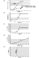
- FIG. 2A to FIG. 2E are diagrams showing simulation results of the compression system according to the embodiment of the present invention.
- FIG. 3A to FIG. 3D are diagrams showing simulation results of the compression system according to the comparative example.
- FIG. 1 is a diagram showing a liquefaction process of a natural gas liquefaction plant to which a compression system 10 according to an embodiment of the present invention is applied.
- FIG. 1 shows a cooling process using a propane refrigerant and a mixed refrigerant (nitrogen + methane + ethane + propane) (C3-MR system) as refrigerants.
- C3-MR system mixed refrigerant
- the propane refrigerant pressurized by the propane compressor 20 circulates through the propane refrigerant loop L1 shown in FIG. 1, and the mixed refrigerant pressurized by the compression system 10 circulates through the mixed refrigerant loop L2 shown in FIG.
- the propane refrigerant collected from the mixed refrigerant intermediate cooler 22 is pressurized to 16 Bar in the propane compressor 20, and then cooled by heat exchange with cooling water in the propane refrigerant condenser 24. Completely condensed.
- the condensed propane refrigerant is stored in the propane refrigerant receiver 26.
- the propane refrigerant stored in the propane refrigerant receiver 26 is sent to the mixed refrigerant intermediate cooler 22 again.
- the mixed refrigerant heat-exchanged with the natural gas in the main heat exchanger 30 is compressed by the compressor 11 of the compression system 10 and cooled to 45 ° C. by the mixed refrigerant condenser 12 with cooling water.
- This pressurized mixed refrigerant is subjected to sequential heat exchange in the mixed refrigerant intermediate cooler 22 through which propane refrigerant depressurized in three stages flows, and finally cooled to ⁇ 35 ° C. and partially condensed.
- the mixed refrigerant is separated into gas and liquid by the mixed refrigerant separator 28.
- the mixed refrigerant separated into gas and liquid flows into the main heat exchanger 30 respectively, and the natural gas is cooled to ⁇ 162 ° C. and liquefied while exchanging heat.
- the liquefied natural gas is sent to the LNG tank 32.
- the mixed refrigerant evaporated by heat exchange in the main heat exchanger 30 is sent to the compression system 10 again.
- the liquefaction process to which the compression system 10 according to the present embodiment can be applied is not limited to that shown in FIG. 1, and for example, the AP-X method, the cascade method, the DMR method, the SMR method, etc. Applicable.
- FIG. 1 a portion surrounded by a broken line is the compression system 10.
- the compression system 10 includes a compressor 11 that compresses a mixed refrigerant (gas), an electric motor (motor) 13 as a drive unit that drives the compressor 11, and a gas turbine 14.
- the compressor 11 is a rotary compressor. Electric motor 13 and gas turbine 14 are each coaxially coupled to compressor 11. The rotor (not shown) of the compressor 11 is rotationally driven by the drive torque generated by the electric motor 13 and the gas turbine 14.
- the discharge side pipe 15 is connected to the discharge port 11 a of the compressor 11.
- the other end of the discharge side pipe 15 is connected to the mixed refrigerant intermediate cooler 22.
- One end of the suction side pipe 16 is connected to the suction port 11 b of the compressor 11.
- the other end of the suction side pipe 16 is connected to the main heat exchanger 30.
- the discharge side piping is also called “high pressure side piping”, and the suction side piping is also called “low pressure side piping”.
- the discharge side pipe 15 is provided with a mixed refrigerant capacitor 12 and a discharge side valve 17 that opens and closes the discharge side pipe 15.
- the suction side pipe 16 is provided with a suction side valve 18 that opens and closes the suction side pipe 16.
- the compression system 10 further includes an anti-surge pipe 21 and an anti-surge valve 23 that opens and closes the anti-surge pipe 21.
- the antisurge valve 23 is opened, and the refrigerant mixture on the discharge side (high pressure side) of the compressor 11 is returned to the suction side (low pressure side). Thereby, it can prevent that the compressor 11 will be in a surge state.
- the compression system 10 further includes a bypass pipe 25 and a bypass valve 27 that opens and closes the bypass pipe 25.
- the bypass pipe 25 bypass-connects the discharge side pipe 15 and the suction side pipe 16. More specifically, one end of the bypass pipe 25 is connected to the upstream side of the discharge side valve 17 in the discharge side pipe 15. The other end of the bypass pipe 25 is connected to the upstream side of the suction side valve 18 in the discharge side pipe 15.
- the compression system 10 further includes a control unit 40 that controls the operation of the electric motor 13 and the gas turbine 14 and the opening / closing of each valve.
- the control unit 40 opens the discharge side valve 17 and the suction side valve 18 and closes the antisurge valve 23 and the bypass valve 27.
- the compressor 11 compresses the mixed refrigerant supplied from the suction side pipe 16 and supplies the compressed refrigerant to the mixed refrigerant capacitor 12.
- the compressor 11 stops for some reason during normal operation. In this case, there is a high possibility that a large amount of mixed refrigerant remains in the compressor 11. If a large amount of mixed refrigerant remains in the compressor 11, a very large starting torque is required when restarting the compressor 11, and the compressor 11 may not be started smoothly.
- the compression system 10 includes the bypass pipe 25 and the bypass valve 27 that connect the discharge side pipe 15 and the suction side pipe 16 as described above. .
- the control unit 40 closes the discharge side valve 17 and the suction side valve 18. Then, a starting torque is applied to the compressor 11 via the electric motor 13 and the gas turbine 14 to start the rotation of the compressor 11.
- the control unit 40 opens the bypass valve 27 while the rotational speed of the compressor 11 is increasing. (The speeding up may be paused if necessary).
- the mixed refrigerant in the compressor 11 is pumped to the suction side (low pressure side) of the compressor 11 via the bypass pipe 25.
- the refrigerant mixture pumped to the suction side of the compressor 11 is stored in the suction side pipe 16 or the main heat exchanger 30 because the suction side valve 18 is closed.
- the compression system 10 includes the bypass pipe 25 and the bypass valve 27 because the mixed refrigerant remaining in the compressor 11 can be reduced when the compressor 11 is restarted.
- the rotational speed of the compressor 11 can be increased to a predetermined rotational speed in a short time and with a small starting torque. That is, according to the compression system 10 according to the present embodiment, the compressor 11 can be preferably started.
- FIG. 2A to 2E show simulation results of the compression system 10 according to the embodiment of the present invention.
- FIG. 2A is a graph showing a characteristic curve of the compressor (polytrope head with respect to volume flow rate) and an operating point of the compressor.
- FIG. 2B is a graph showing the rotational speed of the compressor with respect to time.
- FIG.2 (c) is a graph which shows the torque of the compressor with respect to time.
- FIG. 2D is a graph showing the torque of the compressor with respect to the rotational speed.
- FIG. 2E is a graph showing the opening degree of the bypass valve 27 with respect to time.
- FIG. 3 (a) to 3 (d) show the simulation results of the compression system according to the comparative example.
- the compression system according to the comparative example has a configuration in which the bypass pipe 25 and the bypass valve 27 are removed from the compression system 10 shown in FIG.
- FIG. 3A is a graph showing a characteristic curve of the compressor (polytrope head with respect to volume flow rate) and an operating point of the compressor.
- FIG. 3B is a graph showing the rotational speed of the compressor with respect to time.
- FIG.3 (c) is a graph which shows the torque of the compressor with respect to time.
- FIG.3 (d) is a graph which shows the torque of the compressor with respect to rotational speed.
- the graph corresponding to FIG.2 (e) does not exist.
- the procedure for starting the compressor 11 is as follows. (1) Start rotation of compressor (2) Necessary torque increases with increase in compressor rotation speed (3) When bypass valve is opened during acceleration of compressor rotation speed, required starting torque is Reduction (4) Startup Completion (1) to (4) shown in FIGS. 2 (a) to 2 (e) correspond to the above steps (1) to (4).
- the torque continues to increase from the start of the start to the completion of the start (about 1600 seconds), and a torque of about 125,000 ft ⁇ lb (ft ⁇ lbf) is required at the maximum.
- the compression system according to the comparative example requires a torque of about 180,000 foot-pounds. Therefore, according to the compression system 10 according to the present embodiment, the torque required for starting is reduced. be able to. Thereby, size reduction and energy saving of the electric motor 13 and the gas turbine 14 can be achieved.
- the bypass pipe 25 is provided so as to connect the discharge side pipe 15 and the suction side pipe 16, but the bypass pipe 25 is different from the discharge side pipe 15 and the compression system 10. It may be provided to connect to the low pressure system.
- the bypass valve 27 when the compressor 11 is started, the bypass valve 27 is opened while the rotation speed of the compressor 11 is increasing. However, before the compressor 11 is started, the bypass valve 27 is opened. 27 may be in an open state.
- the present invention can be used for a plant including a compressor.
Landscapes
- Engineering & Computer Science (AREA)
- Mechanical Engineering (AREA)
- General Engineering & Computer Science (AREA)
- Physics & Mathematics (AREA)
- Thermal Sciences (AREA)
- Control Of Positive-Displacement Pumps (AREA)
Abstract
圧縮システム10は、気体を圧縮する圧縮機11と、圧縮機11を駆動する電動機13およびガスタービン14と、圧縮機11の吐出口11aに接続された吐出側配管15と、圧縮機11の吸込口11bに接続された吸込側配管16と、吐出側配管15と吸込側配管16とをバイパス接続するバイパス配管25と、バイパス配管25を開閉するバイパスバルブ27と、電動機13、ガスタービン14およびバイパスバルブ27を制御する制御部40とを備える。圧縮機11を起動する際に、制御部40は、電動機13およびガスタービン14による圧縮機11の起動前または圧縮機11の回転速度が昇速している途中でバイパスバルブ27を開状態にすることで、圧縮機11内の気体の少なくとも一部をバイパス配管25を介して吸込側配管16に圧送する。
Description
本発明は、圧縮機を備える圧縮システムおよびその起動方法に関する。
従来より、気体を圧縮する圧縮機を含むプラントが知られている。例えば天然ガスの液化プラント(LNGプラント)では、冷却サイクルの冷媒ガスを圧縮するために圧縮機が用いられる(例えば特許文献1参照)。
圧縮機を含むプラントにおいて、何らかの理由で圧縮機が停止した場合、圧縮機内に多量のガス(例えば冷媒ガス)が残留している場合がある。圧縮機内に多量のガスが残留していると、その後圧縮機を再起動する際に、該ガスの影響により非常に大きな起動トルクが必要となり、圧縮機を円滑に起動できない場合がある。圧縮機内のガスを外部に排出すれば圧縮機を起動することが可能となるが、この場合、再起動後、運転開始前にガスをプロセス系内に補充する必要があり、運転コストが増大する。
本発明は、こうした状況を鑑みてなされたものであり、その目的は、圧縮機を好適に起動することのできる技術を提供することにある。
上記課題を解決するために、本発明のある態様の圧縮システムは、気体を圧縮する圧縮機と、圧縮機を駆動する駆動部と、圧縮機の吐出口に接続された吐出側配管と、圧縮機の吸込口に接続された吸込側配管と、吐出側配管と吸込側配管または他の低圧システムとをバイパス接続するバイパス配管と、バイパス配管を開閉するバイパスバルブと、駆動部およびバイパスバルブを制御する制御部とを備える。圧縮機を起動する際に、制御部は、駆動部による圧縮機の起動前または圧縮機の回転速度が昇速している途中でバイパスバルブを開状態にすることで、圧縮機内の気体の少なくとも一部をバイパス配管を介して吸込側配管または他の低圧システムに圧送する。
本発明の別の態様は、圧縮システムの起動方法である。この方法は、気体を圧縮する圧縮機と、圧縮機を駆動する駆動部と、圧縮機の吐出口に接続された吐出側配管と、圧縮機の吸込口に接続された吸込側配管と、吐出側配管と吸込側配管または他の低圧システムとをバイパス接続するバイパス配管と、バイパス配管を開閉するバイパスバルブと、を備える圧縮システムの起動方法であって、駆動部を介して圧縮機を回転させるステップと、圧縮機の起動前または圧縮機の回転速度が昇速している途中でバイパスバルブを開状態にすることで、圧縮機内の気体の少なくとも一部をバイパス配管を介して吸込側配管または他の低圧システムに圧送するステップとを備える。
なお、以上の構成要素の任意の組合せ、本発明の表現を方法、装置、システム、記録媒体、コンピュータプログラムなどの間で変換したものもまた、本発明の態様として有効である。
本発明によれば、圧縮機を好適に起動することができる。
図1は、本発明の実施形態に係る圧縮システム10が適用される天然ガス液化プラントの液化プロセスを示す図である。図1は、冷媒として、プロパン冷媒と混合冷媒(窒素+メタン+エタン+プロパン)を使う方式(C3-MR方式)の冷却プロセスを示す。
プロパン圧縮機20で加圧されるプロパン冷媒は、図1に示すプロパン冷媒ループL1を循環し、圧縮システム10で加圧される混合冷媒は、図1に示す混合冷媒ループL2を循環する。
プロパン冷媒ループL1においては、混合冷媒中間冷却器22から集められたプロパン冷媒が、プロパン圧縮機20において16Barまで加圧された後、プロパン冷媒コンデンサ24にて冷却水との熱交換で冷却されて完全に凝縮される。この凝縮されたプロパン冷媒は、プロパン冷媒レシーバ26に貯留される。プロパン冷媒レシーバ26に貯留されたプロパン冷媒は、再び混合冷媒中間冷却器22に送られる。
混合冷媒ループL2においては、主熱交換器30で天然ガスと熱交換した混合冷媒は、圧縮システム10の圧縮機11で圧縮され、混合冷媒コンデンサ12にて冷却水により45℃まで冷却される。この加圧された混合冷媒は、3段階に減圧されたプロパン冷媒がそれぞれ流通する混合冷媒中間冷却器22において順次熱交換して、最終的に-35℃まで冷却されて、一部凝縮する。そして、混合冷媒は、混合冷媒セパレータ28にて気液分離される。気体と液体に分離された混合冷媒は、それぞれ主熱交換器30に流入し、熱交換しながら天然ガスを-162℃まで冷却して液化する。液化された天然ガスは、LNGタンク32に送られる。主熱交換器30で熱交換により蒸発した混合冷媒は、再び圧縮システム10に送られる。
なお、当然のことながら、本実施形態に係る圧縮システム10が適用可能な液化プロセスは、図1に示すものに限定されず、例えばAP-X方式、カスケード方式、DMR方式、SMR方式などにも適用可能である。
次に、本実施形態に係る圧縮システム10について詳細に説明する。図1において、破線で囲んだ部分が圧縮システム10となる。
図1に示すように、圧縮システム10は、混合冷媒(気体)を圧縮する圧縮機11と、圧縮機11を駆動する駆動部としての電動機(モータ)13およびガスタービン14とを備える。圧縮機11は、回転式の圧縮機である。電動機13およびガスタービン14は、それぞれ圧縮機11に同軸に結合される。電動機13およびガスタービン14が生成する駆動トルクにより、圧縮機11のロータ(図示せず)が回転駆動される。
圧縮機11の吐出口11aには吐出側配管15の一端が接続される。吐出側配管15の他端は混合冷媒中間冷却器22に接続される。圧縮機11の吸込口11bには吸込側配管16の一端が接続される。吸込側配管16の他端は主熱交換器30に接続される。吐出側配管は「高圧側配管」、吸込側配管は「低圧側配管」とも呼ばれる。吐出側配管15には混合冷媒コンデンサ12と、吐出側配管15を開閉する吐出側バルブ17が設けられる。吸込側配管16には吸込側配管16を開閉する吸込側バルブ18が設けられる。
圧縮システム10はさらに、アンチサージ配管21と、アンチサージ配管21を開閉するアンチサージバルブ23とを備える。圧縮機11がサージ状態に近づいた場合、アンチサージバルブ23が開状態とされ、圧縮機11の吐出側(高圧側)の混合冷媒が吸込側(低圧側)に戻される。これにより圧縮機11がサージ状態となることを防止できる。
本実施形態に係る圧縮システム10はさらに、バイパス配管25と、バイパス配管25を開閉するバイパスバルブ27とを備える。バイパス配管25は、吐出側配管15と吸込側配管16とをバイパス接続する。より詳細には、バイパス配管25の一端は、吐出側配管15における吐出側バルブ17より上流側に接続される。バイパス配管25の他端は、吐出側配管15における吸込側バルブ18よりも上流側に接続される。
圧縮システム10はさらに、電動機13およびガスタービン14の動作並びに各バルブの開閉を制御する制御部40を備える。通常の運転状態のとき、制御部40は、吐出側バルブ17および吸込側バルブ18を開状態とし、アンチサージバルブ23およびバイパスバルブ27を閉状態とする。このとき、圧縮機11は、吸込側配管16から供給される混合冷媒を圧縮し、混合冷媒コンデンサ12に供給する。
ここで、通常運転中に何らかの理由で圧縮機11が停止した場合を考える。この場合、圧縮機11内に多量の混合冷媒が残留している可能性が高い。圧縮機11内に多量の混合冷媒が残留していると、圧縮機11を再起動する際に非常に大きな起動トルクが必要となり、圧縮機11を円滑に起動できない場合がある。
そこで、このような課題を解決するために、本実施形態に係る圧縮システム10は、上記のように吐出側配管15と吸込側配管16とを接続するバイパス配管25と、バイパスバルブ27とを備える。圧縮機11を再起動する際、制御部40は、吐出側バルブ17および吸込側バルブ18を閉状態とする。そして、電動機13およびガスタービン14を介して圧縮機11に起動トルクを与え、圧縮機11の回転を開始させる。圧縮機11に与えられる起動トルクに応じて圧縮機11の回転速度が徐々に上昇するが、圧縮機11の回転速度が昇速している途中で、制御部40はバイパスバルブ27を開状態とする(必要に応じて、昇速を一時停止してもよい)。これにより、圧縮機11内の混合冷媒の少なくとも一部がバイパス配管25を介して圧縮機11の吸込側(低圧側)に圧送される。圧縮機11の吸込側に圧送された混合冷媒は、吸込側バルブ18が閉じられているため、吸込側配管16内や主熱交換器30内に貯留される。
このように、本実施形態に係る圧縮システム10では、圧縮機11を再起動する際に、圧縮機11内に残留する混合冷媒を減少させることができるため、バイパス配管25およびバイパスバルブ27を備えていない圧縮システムと比較して、圧縮機11の回転速度を短時間且つ小さい起動トルクで所定の回転速度まで昇速できる。すなわち、本実施形態に係る圧縮システム10によれば、圧縮機11を好適に起動することができる。
図2(a)~図2(e)は、本発明の実施形態に係る圧縮システム10のシミュレーション結果を示す。図2(a)は、圧縮機の特性曲線(体積流量に対するポリトロープヘッド)と、圧縮機の運転点を示すグラフである。図2(b)は、時間に対する圧縮機の回転速度を示すグラフである。図2(c)は、時間に対する圧縮機のトルクを示すグラフである。図2(d)は、回転速度に対する圧縮機のトルクを示すグラフである。図2(e)は、時間に対するバイパスバルブ27の開度を示すグラフである。
図3(a)~図3(d)は、比較例に係る圧縮システムのシミュレーション結果を示す。比較例に係る圧縮システムは、図1に示す圧縮システム10から、バイパス配管25およびバイパスバルブ27を取り除いた構成である。図3(a)は、圧縮機の特性曲線(体積流量に対するポリトロープヘッド)と、圧縮機の運転点を示すグラフである。図3(b)は、時間に対する圧縮機の回転速度を示すグラフである。図3(c)は、時間に対する圧縮機のトルクを示すグラフである。図3(d)は、回転速度に対する圧縮機のトルクを示すグラフである。なお、比較例に係る圧縮システムはバイパスバルブを備えていないため、図2(e)に対応するグラフは存在しない。
本実施形態に係る圧縮システム10において、圧縮機11の起動を行う手順は以下の通りである。
(1)圧縮機を回転開始
(2)圧縮機の回転速度の増加に伴って、必要トルクが増加
(3)圧縮機の回転速度の昇速途中でバイパスバルブを開弁すると、必要起動トルクが減少
(4)起動完了
図2(a)~図2(e)に示す(1)~(4)は、上記の手順(1)~(4)に対応している。
(1)圧縮機を回転開始
(2)圧縮機の回転速度の増加に伴って、必要トルクが増加
(3)圧縮機の回転速度の昇速途中でバイパスバルブを開弁すると、必要起動トルクが減少
(4)起動完了
図2(a)~図2(e)に示す(1)~(4)は、上記の手順(1)~(4)に対応している。
図2(e)に示すように、(2)のタイミングでバイパスバルブ27を閉状態から開状態にすると、バイパス配管25を介して混合冷媒が圧縮機11の吸込側に圧送される。これにより、図2(c)に示すような必要起動トルクの減少とともに、図2(b)に示すように圧縮機11の回転速度が急激に上昇し、(4)のタイミングで最低速度(95%=約3400rpm)まで回転数が増加し、起動が成功している。
図2(b)から、起動完了の回転速度(95%回転数)に約1600秒で到達していることが分かる。図3(b)に示すように、比較例に係る圧縮システムでは起動完了の回転速度(95%回転数)に到達するのに約1800秒を要していることから、本実施形態に係る圧縮システム10によれば、起動完了までの時間を短縮できることが分かる。
また、図2(c)から、起動開始から起動完了(約1600秒)までの間に、トルクは増大を続け、最大で125000フィート・ポンド(ft-lbf)程度のトルクが必要となることが分かる。図3(c)に示すように、比較例に係る圧縮システムでは180000フィート・ポンド程度のトルクが必要なことから、本実施形態に係る圧縮システム10によれば、起動に必要なトルクを低減することができる。これにより、電動機13およびガスタービン14の小型化や省エネルギー化を図ることができる。
以上、本発明を実施例をもとに説明した。この実施例は例示であり、それらの各構成要素や各処理プロセスの組合せにいろいろな変形例が可能なこと、またそうした変形例も本発明の範囲にあることは当業者に理解されるところである。
例えば、上述の実施形態では、吐出側配管15と吸込側配管16とを接続するようにバイパス配管25を設けたが、バイパス配管25は、吐出側配管15と、圧縮システム10とは別の他の低圧システムとを接続するように設けられてもよい。
また、上述の実施形態では、圧縮機11を起動する際に、圧縮機11の回転速度が昇速している途中でバイパスバルブ27を開状態としたが、圧縮機11の起動前にバイパスバルブ27を開状態としてもよい。
10 圧縮システム、 11 圧縮機、 12 混合冷媒コンデンサ、 13 電動機、 14 ガスタービン、 15 吐出側配管、 16 吸込側配管、 17 吐出側バルブ、 18 吸込側バルブ、 20 プロパン圧縮機、 21 アンチサージ配管、 22 混合冷媒中間冷却器、 23 アンチサージバルブ、 24 プロパン冷媒コンデンサ、 25 バイパス配管、 26 プロパン冷媒レシーバ、 27 バイパスバルブ、 30 主熱交換器、 40 制御部。
本発明は、圧縮機を備えるプラントに利用できる。
Claims (6)
- 気体を圧縮する圧縮機と、
前記圧縮機を駆動する駆動部と、
前記圧縮機の吐出口に接続された吐出側配管と、
前記圧縮機の吸込口に接続された吸込側配管と、
前記吐出側配管と前記吸込側配管または他の低圧システムとをバイパス接続するバイパス配管と、
前記バイパス配管を開閉するバイパスバルブと、
前記駆動部および前記バイパスバルブを制御する制御部と、
を備え、
前記圧縮機を起動する際に、前記制御部は、前記駆動部による前記圧縮機の起動前または前記圧縮機の回転速度が昇速している途中で前記バイパスバルブを開状態にすることで、前記圧縮機内の気体の少なくとも一部を前記バイパス配管を介して前記吸込側配管または前記他の低圧システムに圧送することを特徴とする圧縮システム。 - 前記吐出側配管を開閉する吐出側バルブと、
前記吸込側配管を開閉する吸込側バルブと、
をさらに備え、
前記バイパス配管の一端は、前記吐出側バルブより上流側に接続され、
前記バイパス配管の他端は、前記吸込側バルブよりも上流側または前記他の低圧システムに接続されることを特徴とする請求項1に記載の圧縮システム。 - 前記圧縮機を起動する際、前記制御部は、前記吐出側バルブおよび前記吸込側バルブは閉状態とすることを特徴とする請求項2に記載の圧縮システム。
- 気体を圧縮する圧縮機と、
前記圧縮機を駆動する駆動部と、
前記圧縮機の吐出口に接続された吐出側配管と、
前記圧縮機の吸込口に接続された吸込側配管と、
前記吐出側配管と前記吸込側配管または他の低圧システムとをバイパス接続するバイパス配管と、
前記バイパス配管を開閉するバイパスバルブと、
を備える圧縮システムの起動方法であって、
前記駆動部を介して前記圧縮機を回転させるステップと、
前記圧縮機の起動前または前記圧縮機の回転速度が昇速している途中で前記バイパスバルブを開状態にすることで、前記圧縮機内の気体の少なくとも一部を前記バイパス配管を介して前記吸込側配管または前記他の低圧システムに圧送するステップと、
を備えることを特徴とする圧縮システムの起動方法。 - 前記圧縮システムは、
前記吐出側配管を開閉する吐出側バルブと、
前記吸込側配管を開閉する吸込側バルブと、
をさらに備え、
前記バイパス配管の一端は、前記吐出側バルブより上流側に接続され、
前記バイパス配管の他端は、前記吸込側バルブよりも上流側または前記他の低圧システムに接続されることを特徴とする請求項4に記載の圧縮システムの起動方法。 - 前記吐出側バルブおよび前記吸込側バルブを閉状態とするステップをさらに備えることを特徴とする請求項5に記載の圧縮システムの起動方法。
Applications Claiming Priority (2)
| Application Number | Priority Date | Filing Date | Title |
|---|---|---|---|
| JP2016-145293 | 2016-07-25 | ||
| JP2016145293A JP2018017128A (ja) | 2016-07-25 | 2016-07-25 | 圧縮システムおよび圧縮システムの起動方法 |
Publications (1)
| Publication Number | Publication Date |
|---|---|
| WO2018020705A1 true WO2018020705A1 (ja) | 2018-02-01 |
Family
ID=61015802
Family Applications (1)
| Application Number | Title | Priority Date | Filing Date |
|---|---|---|---|
| PCT/JP2017/000498 Ceased WO2018020705A1 (ja) | 2016-07-25 | 2017-01-10 | 圧縮システムおよび圧縮システムの起動方法 |
Country Status (2)
| Country | Link |
|---|---|
| JP (1) | JP2018017128A (ja) |
| WO (1) | WO2018020705A1 (ja) |
Cited By (1)
| Publication number | Priority date | Publication date | Assignee | Title |
|---|---|---|---|---|
| JP2023104267A (ja) * | 2022-01-17 | 2023-07-28 | 三菱重工コンプレッサ株式会社 | 圧縮システム、化学プラント、及び圧縮システムの運転方法 |
Citations (2)
| Publication number | Priority date | Publication date | Assignee | Title |
|---|---|---|---|---|
| JPS5615367U (ja) * | 1979-07-16 | 1981-02-09 | ||
| JP2002130146A (ja) * | 2000-10-19 | 2002-05-09 | Kobe Steel Ltd | 油冷圧縮形冷凍機 |
-
2016
- 2016-07-25 JP JP2016145293A patent/JP2018017128A/ja active Pending
-
2017
- 2017-01-10 WO PCT/JP2017/000498 patent/WO2018020705A1/ja not_active Ceased
Patent Citations (2)
| Publication number | Priority date | Publication date | Assignee | Title |
|---|---|---|---|---|
| JPS5615367U (ja) * | 1979-07-16 | 1981-02-09 | ||
| JP2002130146A (ja) * | 2000-10-19 | 2002-05-09 | Kobe Steel Ltd | 油冷圧縮形冷凍機 |
Cited By (2)
| Publication number | Priority date | Publication date | Assignee | Title |
|---|---|---|---|---|
| JP2023104267A (ja) * | 2022-01-17 | 2023-07-28 | 三菱重工コンプレッサ株式会社 | 圧縮システム、化学プラント、及び圧縮システムの運転方法 |
| JP7796540B2 (ja) | 2022-01-17 | 2026-01-09 | 三菱重工コンプレッサ株式会社 | 圧縮システム、化学プラント、及び圧縮システムの運転方法 |
Also Published As
| Publication number | Publication date |
|---|---|
| JP2018017128A (ja) | 2018-02-01 |
Similar Documents
| Publication | Publication Date | Title |
|---|---|---|
| CN102834619B (zh) | 具有一体化的压缩机和泵的单一系统和方法 | |
| EP2035711B1 (en) | Multistage compressor device | |
| CN101646909B (zh) | 带膨胀器速度控制的制冷剂系统 | |
| RU2009130609A (ru) | Многоступенчатая система компрессора/приводного механизма и способ приведения ее в действие | |
| CN107208950A (zh) | 液化气体用冷却装置 | |
| NO337615B1 (no) | Kompressorstartende momentomformer | |
| CN108458548A (zh) | 包括一个离心式压缩机的压缩系和lng设备 | |
| CN114341567B (zh) | 室外单元以及冷冻循环装置 | |
| JP2009138973A (ja) | ヒートポンプ及びその運転方法 | |
| WO2001021958A1 (en) | Screw compressor and refrigerator | |
| EP3408543B1 (en) | Compressor train start-up using variable inlet guide vanes | |
| US8517693B2 (en) | Multi-compressor string with multiple variable speed fluid drives | |
| WO2018020705A1 (ja) | 圧縮システムおよび圧縮システムの起動方法 | |
| CN101449115A (zh) | 冷却循环系统、天然气液化设备、冷却循环系统的运转方法及改造方法 | |
| JP6947732B2 (ja) | 可変入口ガイドベーンを使用した圧縮機列の始動 | |
| WO2010140324A1 (ja) | 冷凍サイクル装置 | |
| EP4145061A1 (en) | Refrigerating apparatus | |
| CN109579332B (zh) | 制冷系统 | |
| JP4976426B2 (ja) | 冷凍サイクル系統、天然ガス液化設備、及び冷凍サイクル系統の改造方法 | |
| JPS6360300B2 (ja) | ||
| JP2003214380A (ja) | 遠心圧縮機および冷凍機 | |
| JPS5969661A (ja) | 冷凍サイクル | |
| CN105849412A (zh) | 螺杆压缩机 | |
| JP5090932B2 (ja) | エコノマイザを備えた遷臨界運転のための冷却装置 | |
| JP2005257103A (ja) | 冷凍空調装置 |
Legal Events
| Date | Code | Title | Description |
|---|---|---|---|
| 121 | Ep: the epo has been informed by wipo that ep was designated in this application |
Ref document number: 17833717 Country of ref document: EP Kind code of ref document: A1 |
|
| NENP | Non-entry into the national phase |
Ref country code: DE |
|
| 122 | Ep: pct application non-entry in european phase |
Ref document number: 17833717 Country of ref document: EP Kind code of ref document: A1 |