WO2018016186A1 - 回転コネクタ - Google Patents
回転コネクタ Download PDFInfo
- Publication number
- WO2018016186A1 WO2018016186A1 PCT/JP2017/019910 JP2017019910W WO2018016186A1 WO 2018016186 A1 WO2018016186 A1 WO 2018016186A1 JP 2017019910 W JP2017019910 W JP 2017019910W WO 2018016186 A1 WO2018016186 A1 WO 2018016186A1
- Authority
- WO
- WIPO (PCT)
- Prior art keywords
- light
- light receiving
- rotating body
- light emitting
- receiving elements
- Prior art date
- Legal status (The legal status is an assumption and is not a legal conclusion. Google has not performed a legal analysis and makes no representation as to the accuracy of the status listed.)
- Ceased
Links
Images




Classifications
-
- G—PHYSICS
- G08—SIGNALLING
- G08C—TRANSMISSION SYSTEMS FOR MEASURED VALUES, CONTROL OR SIMILAR SIGNALS
- G08C23/00—Non-electrical signal transmission systems, e.g. optical systems
- G08C23/04—Non-electrical signal transmission systems, e.g. optical systems using light waves, e.g. infrared
-
- H—ELECTRICITY
- H04—ELECTRIC COMMUNICATION TECHNIQUE
- H04B—TRANSMISSION
- H04B10/00—Transmission systems employing electromagnetic waves other than radio-waves, e.g. infrared, visible or ultraviolet light, or employing corpuscular radiation, e.g. quantum communication
- H04B10/11—Arrangements specific to free-space transmission, i.e. transmission through air or vacuum
- H04B10/114—Indoor or close-range type systems
-
- H—ELECTRICITY
- H04—ELECTRIC COMMUNICATION TECHNIQUE
- H04B—TRANSMISSION
- H04B10/00—Transmission systems employing electromagnetic waves other than radio-waves, e.g. infrared, visible or ultraviolet light, or employing corpuscular radiation, e.g. quantum communication
- H04B10/80—Optical aspects relating to the use of optical transmission for specific applications, not provided for in groups H04B10/03 - H04B10/70, e.g. optical power feeding or optical transmission through water
-
- H—ELECTRICITY
- H10—SEMICONDUCTOR DEVICES; ELECTRIC SOLID-STATE DEVICES NOT OTHERWISE PROVIDED FOR
- H10F—INORGANIC SEMICONDUCTOR DEVICES SENSITIVE TO INFRARED RADIATION, LIGHT, ELECTROMAGNETIC RADIATION OF SHORTER WAVELENGTH OR CORPUSCULAR RADIATION
- H10F55/00—Radiation-sensitive semiconductor devices covered by groups H10F10/00, H10F19/00 or H10F30/00 being structurally associated with electric light sources and electrically or optically coupled thereto
Definitions
- the present invention relates to a rotary connector that ensures communication between a fixed body and a rotating body.
- a steering roll connector is widely known as a rotating connector that ensures energization between two relatively rotating parts.
- the steering roll connector of Patent Document 1 transmits communication data from a rotating body to a fixed body in a non-contact manner through optical communication.
- the optical communication type rotary connector if the light from the light emitting element becomes dark, the light from the light emitting element may not reach the light receiving element, and optical communication may not be established. Therefore, it has been necessary to reliably establish light communication by allowing the light from the light emitting element to surely reach the light receiving element.
- An object of the present invention is to provide a rotary connector capable of stably establishing optical communication.
- One aspect of the present invention is a rotary connector, which is provided on a fixed body, a rotating body, a plurality of light emitting elements provided on one of the fixed body and the rotating body, and the other of the fixed body and the rotating body.
- a plurality of light receiving elements and using optical communication between the plurality of light emitting elements and the plurality of light receiving elements, the rotating body is rotated between the fixed body and the rotating body.
- the plurality of light receiving elements are non-uniformly arranged with respect to the plurality of light emitting elements.
- the positions of the plurality of light receiving elements are set so that the positions with respect to the plurality of light emitting elements are not uniform.
- the positions of the plurality of light receiving elements are set so that the positions with respect to the plurality of light emitting elements are not uniform.
- the light receiving elements are arranged so as not to be uniform with respect to the light emitting elements, the brightness of the light hitting each light receiving element is not uniform, and a situation where a dark part of the light hits all the light receiving elements occurs. It becomes difficult. Therefore, it is possible to ensure stable communication establishment of optical communication.
- the intervals between the plurality of light receiving elements are not uniform. According to this configuration, it is possible to arrange the plurality of light receiving elements with a simple configuration in which the intervals between the two adjacent light receiving elements are not uniform.
- the plurality of light receiving elements are arranged along a plurality of circles having different diameters around the rotation axis of the rotating body. According to this configuration, it is possible to simply arrange the light receiving elements in a plurality of movement paths having different diameters.
- the rotary connector further includes a light guide that diffuses and outputs light from the plurality of light emitting elements. According to this configuration, it is possible to uniformly irradiate the light receiving element with the light from the light emitting element, which is advantageous in ensuring stable communication establishment of optical communication.
- Another aspect of the present invention is a rotary connector, which is provided on a fixed body, a rotating body, a plurality of light emitting elements provided on one of the fixed body and the rotating body, and the other of the fixed body and the rotating body.
- a plurality of light receiving elements and using optical communication between the plurality of light emitting elements and the plurality of light receiving elements, the fixed body and the rotating body in a state where the rotating body is rotated.
- the plurality of light emitting elements are configured to emit light having wavelengths having different values.
- optical communication can be established stably.
- the side view which shows the structure of the rotation connector of 1st Embodiment.
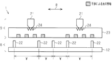
- the top view of the fixed body which shows the arrangement pattern of a light emitting element and a light receiving element.
- the model figure which shows the relationship between the brightness of light by interference, and the arrangement position of a light receiving element.
- the electrical block diagram of a rotation connector The communication sequence figure which shows the drive pattern of a light emitting element.
- the model figure which shows the relationship between the brightness of light by interference, and the position of a light receiving element in the rotation connector of conventional positioning.
- the top view of the fixed body which shows the arrangement pattern of the light emitting element and light receiving element of 2nd Embodiment.
- the model figure which shows the arrangement pattern of the light emitting element and light receiving element of 3rd Embodiment.
- the rotary connector 1 is attached to a vehicle body 2 on the fixed side and a steering shaft 3 on the rotating side in the vehicle.
- the rotary connector 1 performs communication between the vehicle body 2 and the steering shaft 3 in a non-contact manner, and ensures communication between the two members even when the steering shaft 3 is rotated.
- the vehicle includes a steering wheel 3a attached to the steering shaft 3, a detection unit 4 provided on the steering wheel 3a and capable of detecting various operations on the steering wheel 3a, and a controller 5 provided on the vehicle body 2.
- the detection unit 4 detects an operation on the steering wheel 3a and generates an output signal Sout corresponding to the operation.
- the rotary connector 1 receives the output signal Sout from the detection unit 4 and transmits the output signal Sout to the controller 5.
- the controller 5 is composed of an ECU (Electronic Control Unit) that manages the operation of the rotary connector 1 and determines the detection state of the detection unit 4 based on the output signal Sout.
- ECU Electronic Control Unit
- the detection unit 4 may include a switch or a sensor, for example, and may supply an on / off signal detected by the switch or sensor as the output signal Sout.
- the sensor may include an image sensor, and the detection unit 4 may supply a data signal detected by the sensor as the output signal Sout.
- the rotary connector 1 includes a fixed body 8 attached and fixed to the vehicle body 2 and a rotating body 9 that rotates with respect to the fixed body 8.
- both the fixed body 8 and the rotating body 9 have a substantially disk shape and are disposed on the same axis (axis L1).
- the axis L1 is the rotational axis of the steering shaft 3.
- the fixed body 8 includes a substrate 12 on which electrical components on the fixed body 8 side are mounted.
- the steering shaft 3 is rotatably inserted through insertion holes (not shown) formed at the centers of the fixed body 8 and the substrate 12.
- the rotating body 9 includes a substrate 13 on which electrical components on the rotating body 9 side are mounted.
- the rotating body 9 and the substrate 13 are fixed on the same axis with respect to the steering shaft 3.
- the rotary connector 1 has an optical communication type communication method, and notifies the other party of a signal to be communicated between the fixed body 8 and the rotating body 9 according to the presence or absence of light.
- the rotating body 9 optically communicates the output signal Sout of the detection unit 4 of the steering wheel 3a to the fixed body 8 as communication data Sd.
- the communication data Sd constructs binarized information composed of data groups of “0” and “1” by combining light “present” and “absent”.
- the steering wheel 3a may be provided with a plurality of detection units 4.
- communication data Sd can be communicated at high speed (high-speed communication).
- the rotary connector 1 includes two light emitting elements 21 that project light in optical communication and a plurality of light receiving elements 22 that receive light from each light emitting element 21.
- the two light emitting elements 21 are, for example, LEDs.
- the two light emitting elements 21 are attached to the back surface of the substrate 13 and are arranged to face each other with the axis L1 of the rotating body 9 in between.
- the plurality of light receiving elements 22 are attached to the front surface of the substrate 12 facing the back surface of the substrate 13, and are arranged along a circle centered on the axis L ⁇ b> 1 of the rotating body 9.
- the plurality of light receiving elements 22 are arranged at the position of the fixed body 8 facing the circumferential movement path K (see FIG. 2) along which the two light emitting elements 21 move when the rotating body 9 rotates.
- the plurality of light receiving elements 22 are non-uniformly arranged with respect to the two light emitting elements 21. This is to prevent the positional relationship between the light emitting element 21 and the light receiving element 22 from being the same.
- the plurality of light receiving elements 22 are arranged such that the interval W between two adjacent light receiving elements 22 is non-uniform. That is, the intervals between the plurality of light receiving elements 22 are not uniform.
- the rotary connector 1 includes a light guide (light guide plate) 23 that diffuses and outputs the light of the two light emitting elements 21.
- the light guide 23 irradiates the plurality of light receiving elements 22 with the light from each light emitting element 21 as uniform high luminance light.
- the light guide 23 has a plate shape, for example, and includes two slit portions 24 for diffusion formed to face the two light emitting elements 21 respectively.
- the rotary connector 1 includes an output processing unit 25 that controls the operation of the two light emitting elements 21.
- the output processing unit 25 is preferably an IC provided on the rotating body 9 and mounted on the substrate 13, for example.
- the output processing unit 25 switches the process (light on / off) of driving or not driving the light emitting elements 21, so that each light emitting element 21 has a light emission pattern according to the binarized information of the communication data Sd. Generate. The light of this light emission pattern is received by at least one of the plurality of light receiving elements 22.
- the rotary connector 1 includes a signal processing unit 26 that acquires communication data Sd from the transmission side (in this example, the output signal Sout of the detection unit 4) based on the light reception signal Sr of the light receiving element 22.
- the signal processing unit 26 is provided in the controller 5.
- the signal processing unit 26 receives the light reception signal Sr from the light receiving element 22, determines the data content of the communication data Sd based on the light reception signal Sr, and executes an operation according to the communication data Sd.
- the detection unit 4 detects an operation on the steering wheel 3 a and generates an output signal Sout corresponding to the detected operation.
- the output processing unit 25 receives the output signal Sout from the detection unit 4 and transmits communication data Sd of a binary code corresponding to the output signal Sout to the fixed body 8 through optical communication.
- the output processing unit 25 turns on the two light emitting elements 21 when outputting the binarized information “1”, and turns off the two light emitting elements 21 when outputting the binarized information “0”. Let Thus, the output processing unit 25 transmits the communication data Sd of the binarized information to the fixed body 8 by turning on or off the two light emitting elements 21.
- the output processing unit 25 first transmits a preamble signal and the like, and then transmits, for example, a 1-byte (8-bit) signal group a plurality of times, thereby transmitting the communication data Sd through the optical communication to the fixed body 8. Send to. That is, when the timing for starting data transmission arrives, the output processing unit 25 transmits the communication data Sd to the fixed body 8 through optical communication by repeatedly transmitting a 1-byte signal group a predetermined number of times.
- the plurality of light receiving elements 22 are arranged so as to be non-uniform (not equally spaced) in the rotating direction of the rotating body 9 (direction of arrow R in FIG. 3).
- the interval W between the second light receiving element 22 from the left and the adjacent light receiving elements 22 is not uniform.
- the plurality of light receiving elements 22 do not simultaneously face the light and dark portions of the light. Therefore, it can be seen that it is advantageous to ensure the reception accuracy of optical communication.
- the plurality of light receiving elements 22 are non-uniformly arranged with respect to the two light emitting elements 21. Specifically, the intervals W between the plurality of light receiving elements 22 are not uniform. By the way, light has luminance, and if a plurality of light receiving elements 22 are uniformly arranged with regularity, a dark portion of light may hit all the light receiving elements 22. In this case, each light receiving element 22 cannot receive a sufficient amount of light, and optical communication is not stable. Therefore, in the first embodiment, the arrangement pattern of the plurality of light receiving elements 22 viewed from the light emitting element 21 is made non-uniform so that the plurality of light receiving elements 22 are non-uniformly arranged with respect to the light emitting element 21. The brightness of the light in the plurality of light receiving elements 22 is not uniform, and it is difficult for all the light receiving elements 22 to hit the dark part of the light. Therefore, stable establishment of optical communication can be ensured.
- the intervals W between the plurality of light receiving elements 22 are not uniform. Thereby, arrangement
- the rotary connector 1 includes a light guide 23 that diffuses and outputs the light of each light emitting element 21. Therefore, it is possible to uniformly irradiate the light receiving element 22 with the light of each light emitting element 21 by the light guide 23, which is advantageous for ensuring stable establishment of optical communication.
- two light emitting elements 21 are provided. For this reason, it is possible to increase the amount of light received by each light receiving element 22. Therefore, it is further advantageous to ensure stable establishment of optical communication.
- a rotary connector 1 according to a second embodiment embodying the present invention will be described with reference to FIG.
- the second embodiment is different from the first embodiment in the arrangement method of the plurality of light receiving elements 22. Therefore, in 2nd Embodiment, the same code
- the plurality of light receiving elements 22a and 22b are arranged along a plurality of movement paths K1 and K2 in which the diameters of the light emitting elements 21 are different. That is, the plurality of light receiving elements 22a and the plurality of light receiving elements 22b correspond to the plurality of movement paths K1 and K2 having different diameters of the light emitting elements 21, and are disposed so as to face the corresponding movement paths. Specifically, a plurality of light receiving elements 22a are arranged on a moving path K1 closer to the inner side in the radial direction of the rotating body 9, and a plurality of light receiving elements 22b are arranged on a moving path K2 closer to the outer side in the radial direction of the rotating body 9. ing.
- the plurality of light receiving elements 22 are arranged along two circles that have the rotation axis of the rotating body 9 as a center and have different diameters. Therefore, it is possible to ensure the reception accuracy of optical communication. Further, the light receiving elements 22a and 22b can be arranged in a simple configuration in which the light receiving elements 22a and 22b are arranged in a plurality of moving paths K1 and K2 having different diameters.
- a rotary connector 1 according to a third embodiment embodying the present invention will be described with reference to FIG.
- the third embodiment is different from the first embodiment in the wavelength of light emitted from the light emitting element 21.
- the same parts as those in the first embodiment are denoted by the same reference numerals, detailed description thereof is omitted, and only different parts are described in detail.
- a plurality (two in this example) of light emitting elements 21 are configured to irradiate light having different values of wavelength ⁇ .
- the first light emitting element 21a emits light having a wavelength “ ⁇ a”
- the second light emitting element 21b emits light having a wavelength “ ⁇ b”.
- the position where the light interference from the first light emitting element 21a occurs is different from the position where the light interference from the second light emitting element 21b occurs.
- interference of light from the first and second light emitting elements 21a and 21a does not occur at the same time, and it is possible to ensure reception accuracy of optical communication.
- Embodiment is not limited to the configuration described so far, and may be modified as follows. -In 1st Embodiment, it is not limited to all the space
- the binarization information may be “0” when the light is turned on and “1” when the light is turned off.
- two light emitting elements 21 are provided, but the number of light emitting elements 21 may be three or more, or may be one.
- each light emitting element 21 can apply members other than LED.
- the two light emitting elements 21 and the plurality of light receiving elements 22 are not limited to be provided on the substrates 12 and 13, but may be disposed on the fixed body 8 and the rotating body 9.
- route by optical communication is not restricted to implement
- a control line and a power line may be sufficient.
- the communication data Sd is not limited to a multiplexed signal, and may be data constructed only from the output of one detection unit 4.
- the light guide 23 can be omitted.
- two light emitting elements 21 may be provided on the fixed body 8 and a plurality of light receiving elements 22 may be provided on the rotating body 9.
- the rotation connector 1 is not limited to being applied to a vehicle, You may use it for another apparatus and apparatus.
- the present disclosure includes the following implementation examples. Reference symbols are used for ease of understanding rather than limitation.
- Example 1 A fixed body (8); and a rotating body (9) that faces the fixed body (8) and is rotatable about an axis (L1).
- the fixed body (8) and the rotating body (9) The rotary connector (1) capable of performing optical communication with the A plurality of light emitting elements (21) provided on one of the fixed body (8) and the rotating body (9) and irradiating light in the optical communication;
- a plurality of light receiving elements (22) provided on the other of the fixed body (8) and the rotating body (9) and receiving light from the plurality of light emitting elements (21) in the optical communication,
- the plurality of light receiving elements (22) are non-uniformly arranged with respect to the plurality of light emitting elements (21), or the plurality of light emitting elements (21) irradiate light having wavelengths having different values. Configured as follows.
Landscapes
- Physics & Mathematics (AREA)
- Electromagnetism (AREA)
- Engineering & Computer Science (AREA)
- Computer Networks & Wireless Communication (AREA)
- Signal Processing (AREA)
- General Physics & Mathematics (AREA)
- Optical Communication System (AREA)
- Arrangements For Transmission Of Measured Signals (AREA)
- Steering Controls (AREA)
- Photo Coupler, Interrupter, Optical-To-Optical Conversion Devices (AREA)
- Mechanical Coupling Of Light Guides (AREA)
Abstract
回転コネクタ1は、固定体8と、回動体9と、固定体8及び回動体9の一方に設けられた複数の発光素子21と、固定体8及び回動体9の他方に設けられた複数の受光素子22と、を備える。回転コネクタ1は、複数の発光素子21と複数の受光素子22との間の光通信を用いて、回動体9が回動した状態において固定体8と回動体9との間の通信を実行可能である。複数の受光素子22は、複数の発光素子21に対して不均一に配置されているか、または異なる値を有する波長の光を照射するように構成される。
Description
本発明は、固定体と回動体との間の通信を確保する回転コネクタに関する。
従来、相対的に回転する2部品間の通電を確保する回転コネクタとして、ステアリングロールコネクタが広く知られている。特許文献1のステアリングロールコネクタは、光通信を通じて非接触で通信データを回動体から固定体に送信している。
光通信型の回転コネクタでは、発光素子からの光が暗くなってしまうと、発光素子からの光が受光素子まで到達せずに光通信が成立しない可能性がある。よって、発光素子からの光を受光素子に確実に到達させて、光通信を安定して成立させる必要があった。
本発明の目的は、光通信を安定して成立させることができる回転コネクタを提供することにある。
本発明の一側面は、回転コネクタであって、固定体と、回動体と、前記固定体及び回動体の一方に設けられた複数の発光素子と、前記固定体及び回動体の他方に設けられた複数の受光素子と、を備え、前記複数の発光素子と前記複数の受光素子との間の光通信を用いて、前記回動体が回動した状態において前記固定体と前記回動体との間の通信を実行可能な回転コネクタにおいて、前記複数の受光素子は、前記複数の発光素子に対して不均一に配置されていることを特徴とする。
本発明の一側面は、回転コネクタであって、固定体と、回動体と、前記固定体及び回動体の一方に設けられた複数の発光素子と、前記固定体及び回動体の他方に設けられた複数の受光素子と、を備え、前記複数の発光素子と前記複数の受光素子との間の光通信を用いて、前記回動体が回動した状態において前記固定体と前記回動体との間の通信を実行可能な回転コネクタにおいて、前記複数の受光素子は、前記複数の発光素子に対して不均一に配置されていることを特徴とする。
本構成によれば、複数の受光素子を配置するにあたり、複数の発光素子に対する位置が均一とならないように、複数の受光素子の位置を設定する。ところで、複数の光源では光の干渉による輝度の明暗があり、仮に受光素子の群が規則性をもって均一に配置されていると、全ての受光素子に光の暗い部分が当たってしまう状況に陥る可能性がある。こうなると、発光素子の光が十分な光量で受光素子に届かず、通信が安定しない。そこで、本構成の場合、受光素子を発光素子に対して均一にならないように配置したので、各受光素子に当たる光の明暗が一律でなくなり、全ての受光素子に光の暗い部分が当たる状況が生じ難くなる。よって、光通信の安定した通信成立性を確保することが可能となる。
上記回転コネクタにおいて、前記複数の受光素子の間隔が不均一となっていることが好ましい。この構成によれば、複数の受光素子の配置を、隣同士の2つの受光素子の間隔を不均一とする簡素な構成で済ませることが可能となる。
上記回転コネクタにおいて、前記複数の受光素子は、前記回動体の回動軸を中心とし且つ異なる径を有する複数の円に沿って配置されていることが好ましい。この構成によれば、受光素子の配置を、径が異なる複数の移動経路に配置するという簡素な構成で済ませることが可能となる。
上記回転コネクタにおいて、前記複数の発光素子の光を拡散して出力するライトガイドをさらに備えることが好ましい。この構成によれば、発光素子の光をライトガイドによって受光素子に均一に照射することが可能となるので、光通信の安定した通信成立性を確保するのに有利となる。
本発明の他の側面は、回転コネクタであって、固定体と、回動体と、前記固定体及び回動体の一方に設けられた複数の発光素子と、前記固定体及び回動体の他方に設けられた複数の受光素子と、を備え、前記複数の発光素子と前記複数の受光素子との間の光通信を用いて、前記回動体が回動した状態において前記固定体と前記回動体との間の通信を実行可能な回転コネクタにおいて、前記複数の発光素子は、異なる値を有する波長の光を照射するように構成されることを特徴とする。
本発明によれば、光通信を安定して成立させることができる。
(第1実施形態)
以下、本発明を具体化した第1実施形態の回転コネクタ1を図1~図6を参照して説明する。
以下、本発明を具体化した第1実施形態の回転コネクタ1を図1~図6を参照して説明する。
図1に示すように、回転コネクタ1は、車両において、固定側となる車体2と、回動側となるステアリングシャフト3とに取り付けられている。回転コネクタ1は、車体2とステアリングシャフト3との間の通信を非接触で行って、これら2者間の通信をステアリングシャフト3が回動されても確保する。車両は、ステアリングシャフト3に取り付けられたステアリングホイール3aと、ステアリングホイール3aに設けられ且つステアリングホイール3aに対する種々の操作を検出可能な検知部4と、車体2に設けられたコントローラ5と、を含む。検知部4は、ステアリングホイール3aに対する操作を検出し、その操作に応じた出力信号Soutを生成する。回転コネクタ1は、検知部4からの出力信号Soutを受け取り、その出力信号Soutをコントローラ5に送信する。コントローラ5は、回転コネクタ1の作動を管理するECU(Electronic Control Unit)からなり、出力信号Soutを基に検知部4の検知状態を判断する。
検知部4は、例えばスイッチまたはセンサを含み、出力信号Soutとしてスイッチまたはセンサにより検出されたオンオフ信号を供給してもよい。センサは、画像センサを含んでもよく、検知部4は、出力信号Soutとしてセンサにより検出されたデータ信号を供給してもよい。
回転コネクタ1は、車体2に取り付け固定される固定体8と、固定体8に対して回動する回動体9とを備える。例えば、固定体8及び回動体9は、ともに略円板形状を有し、同一軸心(軸L1)上に配置されている。軸L1は、ステアリングシャフト3の回動軸心である。
固定体8は、固定体8側の電装品が実装される基板12を備える。ステアリングシャフト3は、固定体8及び基板12の各々の中心に形成された挿通孔(図示略)に回動可能に挿通されている。回動体9は、回動体9側の電装品が実装される基板13を備える。回動体9及び基板13は、ステアリングシャフト3に対し、同一軸心上に固定されている。ステアリングシャフト3が回動されたとき、回動体9は、固定体8に支持されるとともに、ステアリングシャフト3と軸L1回り(図1の矢印R方向)に一体回動する。
回転コネクタ1は、光通信型の通信方式を備え、固定体8及び回動体9の間で通信する信号を、光の有無に応じて相手側に通知する。第1実施形態では、回動体9は、ステアリングホイール3aの検知部4の出力信号Soutを、通信データSdとして固定体8に光通信する。通信データSdは、光の「有り」及び「無し」の組み合わせにより、「0」及び「1」のデータ群からなる2値化情報を構築する。またステアリングホイール3aには、複数の検知部4が設けられてもよい。この場合、回動体9は、通信データSdとして、複数の検知部4から出力される信号を時分割によりまとめた多重信号を光通信することが好ましい。光通信は、通信データSdを高速で通信すること(高速通信)が可能である。
図1及び図2に示すように、回転コネクタ1は、光通信において光を投光する2つの発光素子21と、各発光素子21からの光を受光する複数の受光素子22と、を備える。2つの発光素子21は、例えばLEDからなる。2つの発光素子21は、基板13の裏面に取り付けられ、回動体9の軸L1を挟んで互いに対向して配置されている。複数の受光素子22は、基板13の裏面と対向する基板12の表面に取り付けられ、回動体9の軸L1を中心とする円に沿って配置されている。複数の受光素子22を設けることによって、回動体9がどの回転角にあっても、各発光素子21の光を少なくとも1つの受光素子22に到達させることができる。複数の受光素子22は、回動体9の回動時に2つの発光素子21が移動する周状の移動経路K(図2参照)と対向する固定体8の位置に配置されている。
図2及び図3に示すように、複数の受光素子22は、2つの発光素子21に対して不均一に配置されている。これは、発光素子21と受光素子22との位置関係が同一となることを防ぐためである。第1実施形態では、複数の受光素子22は、隣接する2つ受光素子22の間隔Wが不均一となるように配置されている。つまり、複数の受光素子22の間隔が不均一となっている。
図3に示すように、回転コネクタ1は、2つの発光素子21の光を拡散して出力するライトガイド(導光板)23を備える。ライトガイド23は、各発光素子21の光を均一の高輝度の光にして複数の受光素子22に照射する。ライトガイド23は、例えば板状をなし、2つの発光素子21とそれぞれ対向して形成された拡散用の2つのスリット部24を含む。
図4に示すように、回転コネクタ1は、2つの発光素子21の作動を制御する出力処理部25を備える。出力処理部25は、回動体9に設けられ、例えば基板13に実装されたICであることが好ましい。出力処理部25は、発光素子21を駆動させるか、又は駆動させないという処理(光の点灯/消灯)を切り替えることにより、各発光素子21に通信データSdの2値化情報に準じた発光パターンを生成させる。この発光パターンの光が、複数の受光素子22のうちの少なくとも1つに受光される。
回転コネクタ1は、受光素子22の受光信号Srを基に送信側からの通信データSd(本例は検知部4の出力信号Sout)を取得する信号処理部26を備える。信号処理部26は、コントローラ5に設けられている。信号処理部26は、受光素子22から受光信号Srを受け取り、この受光信号Srを基に通信データSdのデータ内容を判断し、この通信データSdに応じた作動を実行する。
次に、図3、図5及び図6を用いて、回転コネクタ1の作用及び効果を説明する。
図5に示すように、例えば検知部4が、ステアリングホイール3aに対する操作を検出し、検出した操作に応じた出力信号Soutを生成する。出力処理部25は、検知部4から出力信号Soutを受け取り、出力信号Soutに応じた2値符号の通信データSdを、光通信を通じて固定体8に送信する。例えば、出力処理部25は、「1」の2値化情報を出力するとき、2つの発光素子21を点灯させ、「0」の2値化情報を出力するとき、2つの発光素子21を消灯させる。このように、出力処理部25は、2つの発光素子21を点灯または消灯させることによって、2値化情報の通信データSdを固定体8に送信する。
図5に示すように、例えば検知部4が、ステアリングホイール3aに対する操作を検出し、検出した操作に応じた出力信号Soutを生成する。出力処理部25は、検知部4から出力信号Soutを受け取り、出力信号Soutに応じた2値符号の通信データSdを、光通信を通じて固定体8に送信する。例えば、出力処理部25は、「1」の2値化情報を出力するとき、2つの発光素子21を点灯させ、「0」の2値化情報を出力するとき、2つの発光素子21を消灯させる。このように、出力処理部25は、2つの発光素子21を点灯または消灯させることによって、2値化情報の通信データSdを固定体8に送信する。
第1実施形態では、出力処理部25は、最初にプリアンブル信号等を送信し、その後に例えば1バイト(8bit)の信号群を複数回送信することによって、通信データSdを光通信を通じて固定体8に送信する。すなわち、データ送信開始のタイミングが到来したとき、出力処理部25は、1バイトの信号群を所定回数繰り返して送信することにより、通信データSdを光通信を通じて固定体8に送信する。
ここで、本発明と比較するために、複数の受光素子22が均一(等間隔)に配置された例を図6を参照して説明する。図6からも分かるように、各発光素子21の光をライトガイド23により効率よく導光させた場合、光の干渉により、基板12の表面において光の明暗が発生し、つまり各受光素子22において光の明暗が発生する。このため、複数の受光素子22を均一(等間隔)に配置した場合、全ての受光素子22が光の明暗部分(光の疎密)に該当することがあり、光通信の受信精度が低下する懸念がある。
一方、図3に示すように、複数の受光素子22は、回動体9の回動方向(図3の矢印R方向)において不均一(等間隔でない)となるように配置されている。例えば、図3において、左から2番目の受光素子22とその両隣の受光素子22との間隔Wが不均一となっている。このため、回動体9の回動時、複数の受光素子22が同時に光の明暗部分に対向することがない。よって、光通信の受信精度を確保するのに有利となることが分かる。
さて、第1実施形態では、複数の受光素子22は、2つの発光素子21に対して不均一に配置されている。具体的には、複数の受光素子22の間隔Wが不均一となっている。ところで、光には輝度があり、仮に複数の受光素子22が規則性を持って均一に配置されていると、全ての受光素子22に光の暗い部分が当たってしまう可能性がある。こうなると、各受光素子22は、十分な光量の光を受光することができずに、光通信が安定しない。そこで、第1実施形態では、複数の受光素子22が発光素子21に対して不均一に配置されるように、発光素子21から見た複数の受光素子22の配置パターンが不均一とされたので、複数の受光素子22における光の明暗が一律でなくなり、全ての受光素子22に光の暗い部分が当たり難くなる。よって、光通信の安定した成立性を確保することができる。
複数の受光素子22の間隔Wが不均一となっている。これにより、複数の受光素子22の配置を、簡素な構成で済ませることができる。
回転コネクタ1は、各発光素子21の光を拡散して出力するライトガイド23を備える。よって、各発光素子21の光をライトガイド23によって受光素子22に一様に照射することが可能となるので、光通信の安定した成立性を確保するのに有利となる。
回転コネクタ1は、各発光素子21の光を拡散して出力するライトガイド23を備える。よって、各発光素子21の光をライトガイド23によって受光素子22に一様に照射することが可能となるので、光通信の安定した成立性を確保するのに有利となる。
第1実施形態では、2つの発光素子21が設けられている。このため、各受光素子22が受光する光の光量を増加させることが可能となる。よって、光通信の安定した成立性を確保するのに一層有利となる。
(第2実施形態)
次に、本発明を具体化した第2実施形態の回転コネクタ1を図7を参照して説明する。なお、第2実施形態は、第1実施形態とは複数の受光素子22の配置方法の点で相違する。よって、第2実施形態では、第1実施形態と同一部分には同じ符号が付されて詳しい説明が省略され、異なる部分についてのみ詳述される。
次に、本発明を具体化した第2実施形態の回転コネクタ1を図7を参照して説明する。なお、第2実施形態は、第1実施形態とは複数の受光素子22の配置方法の点で相違する。よって、第2実施形態では、第1実施形態と同一部分には同じ符号が付されて詳しい説明が省略され、異なる部分についてのみ詳述される。
図7に示すように、複数の受光素子22a,22bは、発光素子21の径が異なる複数の移動経路K1,K2に沿って配置されている。つまり、複数の受光素子22aと複数の受光素子22bとは、発光素子21の径が異なる複数の移動経路K1,K2にそれぞれ対応し、対応する移動経路と対向するように配置されている。具体的には、回動体9の半径方向内側寄りの移動経路K1上に複数の受光素子22aが配置され、回動体9の半径方向外側寄りの移動経路K2上に複数の受光素子22bが配置されている。このように、複数の受光素子22を異なる移動経路K1,K2上に配置することにより、光の干渉が同時に発生しないようにすることが可能となる。つまり、複数の受光素子22a,22bは、回動体9の回動軸を中心とし且つ異なる径を有する2つの円に沿って配置されている。よって、光通信の受信精度を確保することが可能となる。また、受光素子22a,22bの配置を、径が異なる複数の移動経路K1,K2に配置するという簡素な構成で済ませることができる。
(第3実施形態)
次に、本発明を具体化した第3実施形態の回転コネクタ1を図8を参照して説明する。なお、第3実施形態は、第1実施形態とは発光素子21から照射される光の波長の点で相違する。第3実施形態では、第1実施形態と同一部分には同じ符号が付されて詳しい説明が省略され、異なる部分についてのみ詳述される。
次に、本発明を具体化した第3実施形態の回転コネクタ1を図8を参照して説明する。なお、第3実施形態は、第1実施形態とは発光素子21から照射される光の波長の点で相違する。第3実施形態では、第1実施形態と同一部分には同じ符号が付されて詳しい説明が省略され、異なる部分についてのみ詳述される。
図8に示すように、複数(本例は2つ)の発光素子21は、異なる値の波長λを有する光を照射するように構成されている。具体的には、第1の発光素子21aは、波長「λa」の光を照射し、第2の発光素子21bは、波長「λb」の光を照射する。これにより、第1の発光素子21aからの光の干渉が発生する位置は、第2の発光素子21bからの光の干渉が発生する位置と相違する。各受光素子において第1および第2の発光素子21a,21aからの光の干渉が同時に発生せずに、光通信の受信精度を確保することが可能となる。
なお、実施形態はこれまでに述べた構成に限らず、以下の態様に変更してもよい。
・第1実施形態において、全ての間隔Wが異なる値をとることに限定されず、少なくとも1つの間隔Wが他の間隔Wと異なる値に設定されていればよい。
・第1実施形態において、全ての間隔Wが異なる値をとることに限定されず、少なくとも1つの間隔Wが他の間隔Wと異なる値に設定されていればよい。
・各実施形態において、2値化情報は、例えば光が点灯されているときを「0」とし、光が消灯されているときを「1」としてもよい。
・各実施形態において、2つの発光素子21が設けられていたが、発光素子21の数は、3つ以上でもよく、または1つとしてもよい。
・各実施形態において、2つの発光素子21が設けられていたが、発光素子21の数は、3つ以上でもよく、または1つとしてもよい。
・各実施形態において、各発光素子21は、LED以外の他の部材を適用可能である。
・各実施形態において、2つの発光素子21及び複数の受光素子22は、基板12,13上に設けられることに限らず、固定体8や回動体9に配置されていればよい。
・各実施形態において、2つの発光素子21及び複数の受光素子22は、基板12,13上に設けられることに限らず、固定体8や回動体9に配置されていればよい。
・各実施形態において、光通信による経路は、データ線を実現することに限らず、例えば制御線やパワー線であってもよい。
・各実施形態において、通信データSdは、多重信号に限定されず、1つの検知部4の出力のみから構築されるデータでもよい。
・各実施形態において、通信データSdは、多重信号に限定されず、1つの検知部4の出力のみから構築されるデータでもよい。
・各実施形態において、ライトガイド23は、省略することも可能である。
・各実施形態において、2つの発光素子21を固定体8に設け、複数の受光素子22を回動体9に設けてもよい。
・各実施形態において、2つの発光素子21を固定体8に設け、複数の受光素子22を回動体9に設けてもよい。
・各実施形態において、回転コネクタ1は、車両に適用されることに限定されず、他の機器や装置に使用してもよい。
本開示は、以下の実装例を包含する。限定ではなく理解を容易にする目的で参照符号を付した。
本開示は、以下の実装例を包含する。限定ではなく理解を容易にする目的で参照符号を付した。
[実装例1]
固定体(8)と、前記固定体(8)と対向し且つ軸(L1)を中心に回動可能な回動体(9)と、を備え、前記固定体(8)と回動体(9)との間で光通信を実行可能な回転コネクタ(1)は、
前記固定体(8)及び回動体(9)の一方に設けられ、前記光通信において光を照射する複数の発光素子(21)と、
前記固定体(8)及び回動体(9)の他方に設けられ、前記光通信において前記複数の発光素子(21)からの光を受光する複数の受光素子(22)と、を備え、
前記複数の受光素子(22)は、前記複数の発光素子(21)に対して不均一に配置されているか、または
前記複数の発光素子(21)は、異なる値を有する波長の光を照射するように構成される。
固定体(8)と、前記固定体(8)と対向し且つ軸(L1)を中心に回動可能な回動体(9)と、を備え、前記固定体(8)と回動体(9)との間で光通信を実行可能な回転コネクタ(1)は、
前記固定体(8)及び回動体(9)の一方に設けられ、前記光通信において光を照射する複数の発光素子(21)と、
前記固定体(8)及び回動体(9)の他方に設けられ、前記光通信において前記複数の発光素子(21)からの光を受光する複数の受光素子(22)と、を備え、
前記複数の受光素子(22)は、前記複数の発光素子(21)に対して不均一に配置されているか、または
前記複数の発光素子(21)は、異なる値を有する波長の光を照射するように構成される。
本発明の主題は、上記した特定の実施例および変更例の全ての特徴よりも少ない特徴に存在する可能性がある。本発明の範囲は、請求の範囲および等価物の全範囲と共に確定されるべきである。
Claims (5)
- 固定体と、回動体と、前記固定体及び回動体の一方に設けられた複数の発光素子と、前記固定体及び回動体の他方に設けられた複数の受光素子と、を備え、前記複数の発光素子と前記複数の受光素子との間の光通信を用いて、前記回動体が回動した状態において前記固定体と前記回動体との間の通信を実行可能な回転コネクタにおいて、
前記複数の受光素子は、前記複数の発光素子に対して不均一に配置されていることを特徴とする回転コネクタ。 - 前記複数の受光素子の間隔が不均一となっている、請求項1に記載の回転コネクタ。
- 前記複数の受光素子は、前記回動体の回動軸を中心とし且つ異なる径を有する複数の円に沿って配置されている、請求項1に記載の回転コネクタ。
- 前記複数の発光素子の光を拡散して出力するライトガイドをさらに備える請求項1~3のうちいずれか一項に記載の回転コネクタ。
- 固定体と、回動体と、前記固定体及び回動体の一方に設けられた複数の発光素子と、前記固定体及び回動体の他方に設けられた受光素子と、を備え、前記複数の発光素子と前記受光素子との間の光通信を用いて、前記回動体が回動した状態において前記固定体と前記回動体との間の通信を実行可能な回転コネクタにおいて、
前記複数の発光素子は、異なる値を有する波長の光を照射するように構成されることを特徴とする回転コネクタ。
Applications Claiming Priority (2)
| Application Number | Priority Date | Filing Date | Title |
|---|---|---|---|
| JP2016142682A JP2018014596A (ja) | 2016-07-20 | 2016-07-20 | 回転コネクタ |
| JP2016-142682 | 2016-07-20 |
Publications (1)
| Publication Number | Publication Date |
|---|---|
| WO2018016186A1 true WO2018016186A1 (ja) | 2018-01-25 |
Family
ID=60992008
Family Applications (1)
| Application Number | Title | Priority Date | Filing Date |
|---|---|---|---|
| PCT/JP2017/019910 Ceased WO2018016186A1 (ja) | 2016-07-20 | 2017-05-29 | 回転コネクタ |
Country Status (2)
| Country | Link |
|---|---|
| JP (1) | JP2018014596A (ja) |
| WO (1) | WO2018016186A1 (ja) |
Citations (3)
| Publication number | Priority date | Publication date | Assignee | Title |
|---|---|---|---|---|
| JPH05268164A (ja) * | 1992-03-18 | 1993-10-15 | Kao Corp | 相対的に回転する物体間の信号伝送装置 |
| JP2003241003A (ja) * | 2002-02-19 | 2003-08-27 | Yazaki Corp | 信号伝送装置 |
| JP2008252570A (ja) * | 2007-03-30 | 2008-10-16 | Samsung Yokohama Research Institute Co Ltd | 可視光送信装置、可視光受信装置、可視光通信システム、及び可視光通信方法 |
-
2016
- 2016-07-20 JP JP2016142682A patent/JP2018014596A/ja active Pending
-
2017
- 2017-05-29 WO PCT/JP2017/019910 patent/WO2018016186A1/ja not_active Ceased
Patent Citations (3)
| Publication number | Priority date | Publication date | Assignee | Title |
|---|---|---|---|---|
| JPH05268164A (ja) * | 1992-03-18 | 1993-10-15 | Kao Corp | 相対的に回転する物体間の信号伝送装置 |
| JP2003241003A (ja) * | 2002-02-19 | 2003-08-27 | Yazaki Corp | 信号伝送装置 |
| JP2008252570A (ja) * | 2007-03-30 | 2008-10-16 | Samsung Yokohama Research Institute Co Ltd | 可視光送信装置、可視光受信装置、可視光通信システム、及び可視光通信方法 |
Also Published As
| Publication number | Publication date |
|---|---|
| JP2018014596A (ja) | 2018-01-25 |
Similar Documents
| Publication | Publication Date | Title |
|---|---|---|
| WO2008018059A3 (en) | Optical encoder | |
| ATE528665T1 (de) | Laserscanner | |
| US20130242531A1 (en) | Input device having illumination function | |
| US10094469B2 (en) | Apparatus for optoelectronically detecting a selector lever position, selector lever apparatus, method for producing an apparatus and method for optoelectronically detecting a selector lever position wherein predetermined light intensities or filtered wavelengths are assigned to predetermined positions | |
| WO2006014689A3 (en) | Rotary optical switch | |
| CN109839647B (zh) | 激光雷达 | |
| CN106788731B (zh) | 数据传输方法及移动终端 | |
| WO2018016186A1 (ja) | 回転コネクタ | |
| US11988531B2 (en) | System including an optical waveguide for emitting light laterally and a sensor for detect the intensity of the laterally emitted light | |
| JP2009147945A (ja) | 相対回転可能な第1機械部品から第2機械部品への光通信手段を備えた機械 | |
| JP2009147942A6 (ja) | 光信号の伝送装置および方法 | |
| JP2009147942A (ja) | 光信号の伝送装置および方法 | |
| JP2016003947A (ja) | エンコーダ装置、駆動装置、ステージ装置、及びロボット装置 | |
| KR100769882B1 (ko) | 비접촉 커넥터 | |
| WO2018016185A1 (ja) | 回転コネクタ | |
| JP6684671B2 (ja) | 回転コネクタ | |
| WO2018012190A1 (ja) | 回転コネクタ | |
| JP5135222B2 (ja) | 第1および/または第2の光導波領域を有する回転インジケータを備えている自動車用の表示装置 | |
| JP2009163730A6 (ja) | 相対回転可能な両機械部品間におけるデータ伝送手段を備えた機械 | |
| US7668418B2 (en) | Machine with data transfer from one machine part to another machine part which is able to be rotated relative to the one machine part | |
| US20170005721A1 (en) | Method and apparatus for determining a signal transmission quality of a light transmission path | |
| JP2015045618A (ja) | 測色計 | |
| JP6347848B2 (ja) | レーザードップラーセンサ | |
| US7078718B2 (en) | Steering device using optical signal transmission | |
| JP2018016142A (ja) | 回転コネクタ |
Legal Events
| Date | Code | Title | Description |
|---|---|---|---|
| 121 | Ep: the epo has been informed by wipo that ep was designated in this application |
Ref document number: 17830706 Country of ref document: EP Kind code of ref document: A1 |
|
| NENP | Non-entry into the national phase |
Ref country code: DE |
|
| 122 | Ep: pct application non-entry in european phase |
Ref document number: 17830706 Country of ref document: EP Kind code of ref document: A1 |