WO2018012586A1 - 溶接システム - Google Patents
溶接システム Download PDFInfo
- Publication number
- WO2018012586A1 WO2018012586A1 PCT/JP2017/025541 JP2017025541W WO2018012586A1 WO 2018012586 A1 WO2018012586 A1 WO 2018012586A1 JP 2017025541 W JP2017025541 W JP 2017025541W WO 2018012586 A1 WO2018012586 A1 WO 2018012586A1
- Authority
- WO
- WIPO (PCT)
- Prior art keywords
- welding
- wire
- sensor
- welding torch
- feeding
- Prior art date
- Legal status (The legal status is an assumption and is not a legal conclusion. Google has not performed a legal analysis and makes no representation as to the accuracy of the status listed.)
- Ceased
Links
Images




Classifications
-
- B—PERFORMING OPERATIONS; TRANSPORTING
- B23—MACHINE TOOLS; METAL-WORKING NOT OTHERWISE PROVIDED FOR
- B23K—SOLDERING OR UNSOLDERING; WELDING; CLADDING OR PLATING BY SOLDERING OR WELDING; CUTTING BY APPLYING HEAT LOCALLY, e.g. FLAME CUTTING; WORKING BY LASER BEAM
- B23K9/00—Arc welding or cutting
- B23K9/12—Automatic feeding or moving of electrodes or work for spot or seam welding or cutting
-
- B—PERFORMING OPERATIONS; TRANSPORTING
- B23—MACHINE TOOLS; METAL-WORKING NOT OTHERWISE PROVIDED FOR
- B23K—SOLDERING OR UNSOLDERING; WELDING; CLADDING OR PLATING BY SOLDERING OR WELDING; CUTTING BY APPLYING HEAT LOCALLY, e.g. FLAME CUTTING; WORKING BY LASER BEAM
- B23K9/00—Arc welding or cutting
- B23K9/12—Automatic feeding or moving of electrodes or work for spot or seam welding or cutting
- B23K9/124—Circuits or methods for feeding welding wire
-
- B—PERFORMING OPERATIONS; TRANSPORTING
- B23—MACHINE TOOLS; METAL-WORKING NOT OTHERWISE PROVIDED FOR
- B23K—SOLDERING OR UNSOLDERING; WELDING; CLADDING OR PLATING BY SOLDERING OR WELDING; CUTTING BY APPLYING HEAT LOCALLY, e.g. FLAME CUTTING; WORKING BY LASER BEAM
- B23K9/00—Arc welding or cutting
- B23K9/10—Other electric circuits therefor; Protective circuits; Remote controls
- B23K9/1006—Power supply
- B23K9/1043—Power supply characterised by the electric circuit
Definitions
- the present invention relates to a welding system.
- TIG welding Tungsten Inert Gas welding
- GTAW Gas Tungsten Arc welding
- plasma arc welding Non-consumable electrode type gas shielded arc welding is used.
- GMAW Gas Metal Arc Arc welding
- MIG welding Metal Inert Gas welding
- MAG welding Metal Active Gas welding
- carbon dioxide arc welding is also used.
- the consumable electrode type gas shielded arc welding is also referred to as semi-automatic arc welding because the welding is performed manually while the filler wire serving as the consumable electrode is automatically fed.
- a welding torch In these welding methods, generally, a welding torch is used, an arc is generated between the electrode and the work piece (base material), and the work piece is melted by the heat of the arc to form a molten pool (pool). While forming, welding is performed. Further, during welding, shielding gas is released from a torch nozzle surrounding the periphery of the electrode, and welding is performed while shielding the atmosphere (air) with this shielding gas.
- the melting of the base material by the arc and the feeding of the filler wire to the molten pool can be separated and controlled separately.
- the base material can be melted by a stable arc from the tungsten electrode (non-consumable electrode), high-quality welding can be performed.
- the conventional remote control has a drawback that it is not easy to use because the feeding speed of the filler wire cannot be variably adjusted during welding.
- the speed setting of the filler wire is fixed to three conditions of “start”, “main welding”, and “crater”.
- the feeding speed of the filler wire cannot be changed in the middle according to the width of the gap. For this reason, there exists a possibility that a bead may melt away when the wide clearance is reached. On the other hand, when the narrow gap is reached, the feeding speed of the filler wire cannot be lowered, and the back bead may not come out. In addition, in the over-welding of the fixed pipe, it is desired to increase the feeding speed of the filler wire, but even if the point at which the speed is desired to be increased is reached, the feeding speed of the filler wire cannot be changed.
- the welding operator must operate the remote control while holding a welding torch while wearing a leather glove, while finely operating the volume switch provided on the remote control, and the filler wire feed speed It is very difficult to adjust.
- the present invention has been proposed in view of such a conventional situation, and an object thereof is to provide a welding system including a remote controller suitable for manually adjusting the feeding speed of the filler wire.
- the present invention provides the following welding system.
- a welding power supply for supplying a welding current to the welding torch;
- a wire feeding device for feeding a filler wire to the welding torch or a filler guide attached to the welding torch;
- a remote control for manually adjusting the feeding speed of the filler wire;
- a control device for controlling the welding power supply device and the wire feeding device;
- the remote control has a sensor and outputs a signal corresponding to a load applied to the sensor to the control device,
- the said control apparatus controls the said wire feeding apparatus so that the said filler wire may be fed with the feeding speed set according to the output intensity of the said signal,
- the welding system characterized by the above-mentioned.
- the control device controls the welding power supply device so as to supply a welding current set in accordance with a feeding speed of the filler wire to the welding torch (1) ) Welding system.
- the remote controller has a no-reaction interval in which the signal is not output until the load applied to the sensor exceeds a certain value from zero.
- the described welding system (5) The welding system according to (4), wherein the remote controller has a function of adjusting the no-reaction section.
- the control power supply device and the wire feeding device perform the terminal processing for ending the welding when the output intensity of the signal decreases to a certain value during welding.
- the sensor is a pressure-sensitive sensor.
- the remote controller is attached to the welding torch integrally or separately and is operated by a hand operating the welding torch.
- the described welding system (12) The welding system according to any one of (1) to (10), wherein the remote controller is operated separately from a hand that operates the welding torch.
- a consumable electrode type or non-consumable electrode type welding torch A welding power supply for supplying a welding current to the welding torch;
- a wire feeding device for feeding a filler wire to the welding torch or a filler guide attached to the welding torch;
- a remote control for manually adjusting the feeding speed of the filler wire;
- a control device for controlling the welding power supply device and the wire feeding device;
- the remote control has a wire feed stop switch, and can stop the wire feed during welding.
- a consumable electrode type or non-consumable electrode type welding torch a consumable electrode type or non-consumable electrode type welding torch; A welding power supply for supplying a welding current to the welding torch; A wire feeding device for feeding a filler wire to the welding torch or a filler guide attached to the welding torch; A remote control for manually adjusting the feeding speed of the filler wire; A control device for controlling the welding power supply device and the wire feeding device; The remote control has a wire feeding start switch, and the welding system can arbitrarily start feeding a wire during welding.
- the wire feed start switch has a function of adjusting an amount of a signal output when the switch is pressed.
- a welding system including a remote controller suitable for manually adjusting the feeding speed of the filler wire.
- FIG. 1 is a schematic diagram showing the configuration of the welding system 10.
- the welding system 10 of this embodiment schematically includes a welding torch 20, a wire feeding device 30, a welding power source device 40, a remote controller 50, and a control device 60.
- the welding torch 20 is a non-contact type welding torch (TIG welding torch) that is generally used conventionally, and includes a non-consumable electrode 21 that generates an arc with the workpiece (base material) S; And a torch nozzle 22 that discharges a shielding gas toward a molten pool (pool) of the workpiece S generated by the arc.
- TOG welding torch non-contact type welding torch
- the welding torch 20 has a torch switch 23 for switching operation on / off (ON / OFF).
- the torch switch 23 is electrically connected to the control device 60 via the torch switch cable 24.
- the wire feeding device 30 has a filler guide 31 attached to the welding torch 20, and feeds the filler wire W from the tip of the filler guide 31 toward the molten pool of the workpiece S.
- the wire feeding device 30 is electrically connected to the control device 60 via the control cable 32.
- the welding power supply device 40 is a DC and / or AC TIG welding power supply device that has been generally used conventionally, and is connected to the welding torch 20 via the welding cable 41 to the welding torch 20. Supply power and shield gas. Further, the welding power supply device 40 is electrically connected to the control device 60 via the control cable 42.
- the cooling method of the welding torch 20 may be either a water cooling type or an air cooling type.
- a cooling device chloriller
- the welding torch 20 can be cooled by circulation of cooling water (coolant).
- the non-consumable electrode 21 is electrically connected to the minus ( ⁇ ) terminal side via the welding cable 41, and is welded to the plus (+) terminal side via the base material side cable 43.
- the object S is electrically connected.
- the remote controller 50 is for manually adjusting the feeding speed of the filler wire W, and has a sensor 51 attached to the welding torch 20.
- the sensor 51 is a strain gauge and is electrically connected to the control device 60 via the control cable 52. That is, the strain gauge is used to amplify a weak voltage generated by the force applied to the sensor 51 by the welding operator with the amplifier, and the voltage is used for controlling the wire supply speed.
- the control device 60 controls the wire feeding device 30 and the welding power supply device 40. Via the remote controller 50 and the control device 60, it is possible to adjust the welding current, the feeding speed of the filler wire W, which will be described later, and the like at the hand of the welding operator in accordance with the welding conditions.
- an arc is generated between the workpiece S and the non-consumable electrode 21 using the welding torch 20, and the workpiece S is melted by the heat of the arc.
- welding is performed while forming a molten pool (pool).
- the shielding gas is discharged from the torch nozzle 22 surrounding the non-consumable electrode 21, and welding is performed while the atmosphere (air) is blocked by this shielding gas.
- the shielding gas for example, an inert gas such as argon or helium can be used alone or in combination with a plurality of inert gases.
- hydrogen, nitrogen, or the like can be added to the shield gas.
- oxidizing gas since oxidizing gas is not used, the oxidation of the bead formed in a to-be-welded object can be reduced, and wettability can also be improved.
- the filler wire W is automatically fed toward the molten pool of the workpiece S, and welding is performed while the filler wire W is melted in the arc.
- the filler wire W is automatically fed, there is no need to simultaneously supply the filler material and the operation of the welding torch 20 with the left and right hands, and it is stable and stable even without skilled skills. It is possible to perform welding work easily.
- a signal corresponding to the load applied to the sensor 51 is output to the control device 60 via the control cable 52, and the output intensity of this signal is set.
- the control device 60 controls the wire feeding device 30 by the control signal via the control cable 32 so as to feed the filler wire W at the feeding speed set accordingly.
- the load applied to the sensor 51 is proportional to the force applied to the sensor 51 when the welding operator grips the welding torch 20, and the sensor 51 is the force (load) for gripping the welding torch 20.
- a signal with an intensity corresponding to is output.
- the first requirement for the sensor 51 of this embodiment is insensitive response. Further, it is necessary that the operation lower limit value of the sensor 51 can be set freely.
- thick leather gloves are always used to protect the welding operator. Therefore, since the welding torch 20 is gripped and operated with a hand wearing leather gloves, a sensitive feeling like a bare hand cannot be expected.
- a signal corresponding to the gripping force is output after a gripping force (load) exceeding a certain level is applied to the sensor 51.
- the filler wire W is required to be fed at a feeding speed corresponding to the output intensity of this signal.
- the sensor 51 that detects the force applied to the sensor 51 and converts the applied force into an electrical signal and outputs the same as the strain gauge described above is suitable for the present invention.
- the sensor 51 having such a function is not necessarily limited to the above-described strain gauge, and other sensors such as an optical sensor and a pressure sensor may be used.
- an optical sensor it is necessary to devise a sensor so that a protective device such as a leather glove is erroneously sensed in an emergency, which will be described later, and a situation that cannot be properly determined as an emergency occurs.
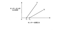
- the relationship between the load applied to the sensor 51 and the output signal is shown in FIG.
- the horizontal axis of the graph shown in FIG. 2 is the load applied to the sensor 51, that is, the force for gripping the sensor 51.
- the vertical axis of the graph shown in FIG. 2 represents the intensity of the signal output from the sensor 51.
- the remote controller 50 has a function of adjusting the output intensity of the signal according to the load applied to the sensor 51.
- the remote controller 50 has a no-reaction interval (play) in which no signal is output until the load applied to the sensor 51 exceeds a certain value from 0 (no load), and further has a function of adjusting this play. is doing.
- Graphs A and B shown in FIG. 2 indicate the force (lower limit value of the operation of the sensor 51) F 1 and F from when the welding operator grips the welding torch 20 until the signal is actually output from the sensor 51, respectively. 2 and the output intensity of the signal according to the force applied to the sensor 51.
- Such a setting is suitable when the feeding speed of the filler wire W needs to be adjusted relatively large. More specifically, it is particularly suitable for welding under the welding conditions such as reverse welding such as temporary welding and butt welding among the main welding.
- graph B when a relatively large force F 2 is not applied does not operate the sensor 51, even if the force applied to the sensor 51 is increased, and represents a case of setting so that the output signal does not change significantly .
- This setting is suitable when fine adjustment is required for the feeding speed of the filler wire W. More specifically, the present welding is suitable for welding under welding conditions with a relatively high deposition rate.
- the filler wire W is fed at a feeding speed set in advance according to the output intensity of this signal. Therefore, it is possible to arbitrarily adjust how much the feeding speed of the filler wire W changes according to the force of gripping the sensor 51. Moreover, it is possible to arbitrarily adjust the non-reaction interval (play) from when the sensor 51 is gripped until the sensor 51 reacts.
- control device 60 controls the welding power supply device 40 so as to supply the welding current set according to the feeding speed of the filler wire W to the welding torch 20. It may be.
- the control device 60 controls the welding power supply device 40 so that the most suitable welding current is supplied to the welding torch 20 according to the feeding speed of the filler wire W. Thus, it is possible to further improve the welding conditions.
- control device 60 causes the wire feeding device 30 and the welding power supply device 40 to stop welding when the output intensity of the signal decreases beyond a certain speed. You may make it control.
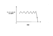
- the second requirement required for the sensor 51 of the present embodiment is safety. Since welding is performed at a high temperature and under a high current, if a safety problem arises and the welding operator releases the welding torch 20, it is necessary to judge the emergency and stop the welding immediately and reliably. is there.
- the strain gauge and the pressure sensitive sensor used as the sensor 51 of the present embodiment take the safety measures described above because the signal output from the sensor 51 is surely reduced when the welding operator releases the welding torch 20. Very suitable on.
- the control device 60 when the output intensity of a signal falls to a fixed value during welding, the control device 60 performs the terminal processing for ending the welding, so that the wire feeding device 30 is used. Further, the welding power supply device 40 may be controlled.
- terminal processing means adjusting the welding current and the feeding speed of the filler wire W or changing the supply condition of the shield gas so that craters or the like are not generated at the welded portion at the end of welding.
- the filler wire W reduces or stops the welding current step by step. And the like, such as temporarily stopping the supply of the gas, changing the supply conditions and gas composition of the shield gas, and the like.
- a strain gauge is used as the sensor 51 of the present embodiment.
- a pressure-sensitive sensor can be used as the sensor 51. That is, when the welding operator applies a force to the sensor 51, the resistance value of the pressure-sensitive sensor changes, and the change is captured as a change in current value, which can be used to control the wire supply speed.
- the type of sensor and the physical quantity (current, voltage, resistance value, etc.) to be used are not limited as long as the welding worker senses the force, operation, movement, etc. applied to the sensor 51.
- the welding system 10 of the present embodiment includes the remote controller 50 suitable for manually adjusting the feeding speed of the filler wire W described above, and the filler is used during welding using the remote controller 50. It is possible to variably adjust the feeding speed of the wire W, stop welding in an emergency, or perform terminal processing after welding.
- the remote controller 50 is not limited to the configuration in which the sensor 51 is separately attached to the welding torch 20 described above, and the sensor 51 may be configured to be integrally attached to the welding torch 20.
- the remote controller 50 may be integrated into the welding torch 20.
- the welding torch 20 instead of the torch switch 23, it is possible to incorporate a function for switching on / off (ON / OFF) the operation of the welding torch 20 into the remote controller 50.
- the filler wire W is fed at a feeding speed corresponding to the gripping force by increasing the gripping force of the welding operator by the welding operator.
- the welding operator reduces the force with which the welding torch 20 is gripped, so that the welding torch 20 is turned off after the termination process described above.
- the remote controller 50 is not limited to the configuration operated by the hand of the welding operator holding the welding torch 20, and may be configured to be operated separately from the hand operating the welding torch 20. For example, by operating the sensor 51 with a remote controller 50 held in the hand opposite to the hand that operates the welding torch 20, or by stepping on the sensor 51 of the remote controller 50 installed separately from the welding torch 20 with a foot. It is also possible to operate.
- the sensor 51 outputs a signal in accordance with the force (load) for gripping the welding torch 20 described above.
- the sensor 51 has a button shape and the force to press the sensor 51 is used. It is also possible to adopt a configuration in which the sensor 51 outputs a signal in response to the above.
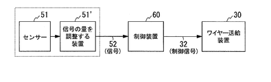
- the sensor 51 used in the remote controller 50 may have a function of adjusting the amount of signal output from the sensor 51.
- the amount of signal refers to the number of signals that are large or within a unit time.
- a pressure sensor and an analog variable resistor or a digital variable resistor can be combined. With this combination, even if the force applied to the pressure sensitive center (gripping force) is the same, the feeding speed of the wire W can be adjusted by adjusting the magnitude of the signal output from the sensor. As shown in FIG.
- the sensor 51 when the sensor 51 includes a device 51 ′ that adjusts the amount of the signal output from the sensor 51, the adjusted signal is output to the control device 60 via the control cable 52, and the control device 60 outputs a control signal to the wire supply device 30 via the control cable 32 based on the adjusted signal. That is, the wire supply speed is controlled based on the adjusted amount of signal.
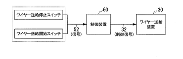
- the wire feed is stopped by the wire feed stop switch provided in the remote controller 50, or the wire feed start switch provided in the remote control is used. You may start paying.
- a signal from the wire supply stop switch or the wire supply start switch is output to the control device 60 via the control cable 52, and the control device 60 supplies the wire in response to this signal. Start or stop supplying wire to the device.
- the wire feed stop switch wire supply stop
- the wire feed start switch wire supply start
- the wire feed stop switch and the wire feed start switch when the wire feed stop switch and the wire feed start switch are pressed, a function for adjusting the amount of signal sent to the control device is added, and the wire feed stop switch and the wire feed start are added. It is good also as a specification which can adjust a wire feeding speed, when a switch is pushed.
- the control device 60 outputs the control signal to the wire supply device according to this signal, and the wire supply speed is adjusted based on the control signal.
- the welding system to which the present invention is applied is not limited to the one applied to the TIG welding described above, but, for example, MAG welding or MIG welding using a consumable electrode type welding torch.
- the present invention can be applied to other welding systems.
Landscapes
- Engineering & Computer Science (AREA)
- Physics & Mathematics (AREA)
- Plasma & Fusion (AREA)
- Mechanical Engineering (AREA)
- Arc Welding Control (AREA)
- Arc Welding In General (AREA)
Abstract
Description
(1) 消耗電極式又は非消耗電極式の溶接用トーチと、
前記溶接用トーチに溶接電流を供給する溶接用電源装置と、
前記溶接用トーチ又は前記溶接用トーチに取り付けられたフィラーガイドにフィラーワイヤーを送給するワイヤー送給装置と、
前記フィラーワイヤーの送給速度を手動で調整するリモコンと、
前記溶接用電源装置及び前記ワイヤー送給装置を制御する制御装置とを備え、
前記リモコンは、センサーを有して、このセンサーに加わる負荷に応じた信号を前記制御装置に出力し、
前記制御装置は、前記信号の出力強度に応じて設定された送給速度で前記フィラーワイヤーを送給するように、前記ワイヤー送給装置を制御することを特徴とする溶接システム。
(2) 前記制御装置は、前記フィラーワイヤーの送給速度に応じて設定された溶接電流を前記溶接用トーチに供給するように、前記溶接用電源装置を制御することを特徴とする前記(1)に記載の溶接システム。
(3) 前記リモコンは、前記センサーに加わる負荷に応じた信号の出力強度を調整する機能を有することを特徴とする前記(1)又は(2)に記載の溶接システム。
(4) 前記リモコンは、前記センサーに加わる負荷が0から一定の値を超えるまで間、前記信号を出力しない無反応区間を有することを特徴とする前記(1)~(3)の何れかに記載の溶接システム。
(5) 前記リモコンは、前記無反応区間を調整する機能を有することを特徴とする前記(4)に記載の溶接システム。
(6) 前記制御装置は、溶接中に前記信号の出力強度が一定の値まで低下したときに、溶接を終了するための端末処理を行うように、前記溶接用電源装置及び前記ワイヤー送給装置を制御することを特徴とする前記(1)~(5)の何れかに記載の溶接システム。
(7) 前記制御装置は、前記信号の出力強度が一定の速度を超えて減少したときに、溶接を停止するように、前記溶接用電源装置及び前記ワイヤー送給装置を制御することを特徴とする前記(1)~(6)の何れかに記載の溶接システム。
(8) 前記センサーが歪みゲージであることを特徴とする前記(1)~(7)の何れかに記載の溶接システム。
(9) 前記センサーが感圧センサーであることを特徴とする前記(1)~(7)の何れかに記載の溶接システム。
(10) 前記センサーは、センサーから出力される信号の量を調整する機能を有することを特徴とする前記(1)~(7)の何れかに記載の溶接システム。
(11) 前記リモコンは、前記溶接用トーチに一体又は別体に取り付けられて、前記溶接用トーチを操作する手により操作されることを特徴とする前記(1)~(10)の何れかに記載の溶接システム。
(12) 前記リモコンは、前記溶接用トーチを操作する手とは別に操作されることを特徴とする前記(1)~(10)の何れか記載の溶接システム。
(13) 消耗電極式又は非消耗電極式の溶接用トーチと、
前記溶接用トーチに溶接電流を供給する溶接用電源装置と、
前記溶接用トーチ又は前記溶接用トーチに取り付けられたフィラーガイドにフィラーワイヤーを送給するワイヤー送給装置と、
前記フィラーワイヤーの送給速度を手動で調整するリモコンと、
前記溶接用電源装置及び前記ワイヤー送給装置を制御する制御装置とを備え、
前記リモコンは、ワイヤー送給停止のスイッチを有して、溶接中にワイヤー送給を停止できることを特徴とする溶接システム。
(14) 消耗電極式又は非消耗電極式の溶接用トーチと、
前記溶接用トーチに溶接電流を供給する溶接用電源装置と、
前記溶接用トーチ又は前記溶接用トーチに取り付けられたフィラーガイドにフィラーワイヤーを送給するワイヤー送給装置と、
前記フィラーワイヤーの送給速度を手動で調整するリモコンと、
前記溶接用電源装置及び前記ワイヤー送給装置を制御する制御装置とを備え、
前記リモコンは、ワイヤー送給開始のスイッチを有して、溶接中に任意にワイヤーが送給を開始できることを特徴とする溶接システム。
(15) 前記ワイヤー送給開始のスイッチにはスイッチが押された際、出力される信号の量を調整する機能を有することを特徴とする前記(14)に記載の溶接システム。
本発明の一実施形態として、例えば図1に示す溶接システム10について説明する。なお、図1は、溶接システム10の構成を示す模式図である。
例えば、溶接作業者が意識的に又は無意識に溶接用トーチ20を離した場合、センサー51から出力される信号が急に低下する。したがって、このセンサー51から出力される信号の減少率(信号の減少量/時間)が一定の値を超えた場合、緊急事態が発生したと判断して、溶接用トーチ20に供給される溶接電流及びフィラーワイヤーWの送給を直ちに停止することができる。
例えば、上記リモコン50は、上述した溶接用トーチ20にセンサー51が別体に取り付けられた構成に限らず、センサー51が溶接用トーチ20に一体に取り付けられた構成とすることも可能である。
つまり、ワイヤー送給速度自体を調整する代わりに、ワイヤー送給停止スイッチ(ワイヤー供給停止)、ワイヤー送給開始スイッチ(ワイヤー供給開始)を交互に用いる事によって、単位時間当たりに供給するワイヤー量を調整し、実質的にワイヤー送給速度自体を調整しても良い。
Claims (15)
- 消耗電極式又は非消耗電極式の溶接用トーチと、
前記溶接用トーチに溶接電流を供給する溶接用電源装置と、
前記溶接用トーチ又は前記溶接用トーチに取り付けられたフィラーガイドにフィラーワイヤーを送給するワイヤー送給装置と、
前記フィラーワイヤーの送給速度を手動で調整するリモコンと、
前記溶接用電源装置及び前記ワイヤー送給装置を制御する制御装置とを備え、
前記リモコンはセンサーを有して、このセンサーに加わる負荷に応じた信号を前記制御装置に出力し、
前記制御装置は、前記信号の出力強度に応じて設定された送給速度で前記フィラーワイヤーを送給するように、前記ワイヤー送給装置を制御することを特徴とする溶接システム。 - 前記制御装置は、前記フィラーワイヤーの送給速度に応じて設定された溶接電流を前記溶接用トーチに供給するように、前記溶接用電源装置を制御することを特徴とする請求項1に記載の溶接システム。
- 前記リモコンは、前記センサーに加わる負荷に応じた信号の出力強度を調整する機能を有することを特徴とする請求項1又は2に記載の溶接システム。
- 前記リモコンは、前記センサーに加わる負荷が0から一定の値を超えるまで間、前記信号を出力しない無反応区間を有することを特徴とする請求項1~3の何れか一項に記載の溶接システム。
- 前記リモコンは、前記無反応区間を調整する機能を有することを特徴とする請求項4に記載の溶接システム。
- 前記制御装置は、溶接中に前記信号の出力強度が一定の値まで低下したときに、溶接を終了するための端末処理を行うように、前記溶接用電源装置及び前記ワイヤー送給装置を制御することを特徴とする請求項1~5の何れか一項に記載の溶接システム。
- 前記制御装置は、前記信号の出力強度が一定の速度を超えて減少したときに、溶接を停止するように、前記溶接用電源装置及び前記ワイヤー送給装置を制御することを特徴とする請求項1~6の何れか一項に記載の溶接システム。
- 前記センサーが歪みゲージであることを特徴とする請求項1~7の何れか一項に記載の溶接システム。
- 前記センサーが感圧センサーであることを特徴とする請求項1~7の何れか一項に記載の溶接システム。
- 前記センサーは、センサーから出力される信号の量を調整する機能を有することを特徴とする請求項1~7の何れか一項に記載の溶接システム。
- 前記リモコンは、前記溶接用トーチに一体又は別体に取り付けられて、前記溶接用トーチを操作する手により操作されることを特徴とする請求項1~10の何れか一項に記載の溶接システム。
- 前記リモコンは、前記溶接用トーチを操作する手とは別に操作されることを特徴とする請求項1~10の何れか一項に記載の溶接システム。
- 消耗電極式又は非消耗電極式の溶接用トーチと、
前記溶接用トーチに溶接電流を供給する溶接用電源装置と、
前記溶接用トーチ又は前記溶接用トーチに取り付けられたフィラーガイドにフィラーワイヤーを送給するワイヤー送給装置と、
前記フィラーワイヤーの送給速度を手動で調整するリモコンと、
前記溶接用電源装置及び前記ワイヤー送給装置を制御する制御装置とを備え、
前記リモコンは、ワイヤー送給停止のスイッチを有して、溶接中にワイヤー送給を停止できることを特徴とする溶接システム。 - 消耗電極式又は非消耗電極式の溶接用トーチと、
前記溶接用トーチに溶接電流を供給する溶接用電源装置と、
前記溶接用トーチ又は前記溶接用トーチに取り付けられたフィラーガイドにフィラーワイヤーを送給するワイヤー送給装置と、
前記フィラーワイヤーの送給速度を手動で調整するリモコンと、
前記溶接用電源装置及び前記ワイヤー送給装置を制御する制御装置とを備え、
前記リモコンは、ワイヤー送給開始のスイッチを有して、溶接中に任意にワイヤーが送給を開始できることを特徴とする溶接システム。 - 前記ワイヤー送給開始のスイッチは、スイッチが押された際、出力される信号の量を調整する機能を有することを特徴とする請求項14に記載の溶接システム。
Priority Applications (4)
| Application Number | Priority Date | Filing Date | Title |
|---|---|---|---|
| US16/315,717 US20190299317A1 (en) | 2016-07-14 | 2017-07-13 | Welding system |
| AU2017297057A AU2017297057A1 (en) | 2016-07-14 | 2017-07-13 | Welding system |
| JP2018527661A JP6995044B2 (ja) | 2016-07-14 | 2017-07-13 | 溶接システム |
| SG11201810988RA SG11201810988RA (en) | 2016-07-14 | 2017-07-13 | Welding system |
Applications Claiming Priority (2)
| Application Number | Priority Date | Filing Date | Title |
|---|---|---|---|
| JP2016-139462 | 2016-07-14 | ||
| JP2016139462 | 2016-07-14 |
Publications (1)
| Publication Number | Publication Date |
|---|---|
| WO2018012586A1 true WO2018012586A1 (ja) | 2018-01-18 |
Family
ID=60953160
Family Applications (1)
| Application Number | Title | Priority Date | Filing Date |
|---|---|---|---|
| PCT/JP2017/025541 Ceased WO2018012586A1 (ja) | 2016-07-14 | 2017-07-13 | 溶接システム |
Country Status (5)
| Country | Link |
|---|---|
| US (1) | US20190299317A1 (ja) |
| JP (1) | JP6995044B2 (ja) |
| AU (1) | AU2017297057A1 (ja) |
| SG (1) | SG11201810988RA (ja) |
| WO (1) | WO2018012586A1 (ja) |
Cited By (1)
| Publication number | Priority date | Publication date | Assignee | Title |
|---|---|---|---|---|
| CN110802305A (zh) * | 2019-11-19 | 2020-02-18 | 龙岩学院 | 弧焊过程参数在线监测装置与监测方法 |
Families Citing this family (1)
| Publication number | Priority date | Publication date | Assignee | Title |
|---|---|---|---|---|
| CN113714587A (zh) * | 2021-08-12 | 2021-11-30 | 中国核电工程有限公司 | 一种焊枪、焊接装置及系统 |
Citations (3)
| Publication number | Priority date | Publication date | Assignee | Title |
|---|---|---|---|---|
| JPS5452640A (en) * | 1977-10-05 | 1979-04-25 | Hitachi Ltd | Welding torch able to regulate wire feeding speed at hand |
| JPS5949466U (ja) * | 1982-09-27 | 1984-04-02 | 三菱電機株式会社 | ア−ク溶接機のト−チ |
| JP2000271142A (ja) * | 1999-03-24 | 2000-10-03 | Olympus Optical Co Ltd | 電気駆動型処置具 |
Family Cites Families (2)
| Publication number | Priority date | Publication date | Assignee | Title |
|---|---|---|---|---|
| JPS5838674A (ja) * | 1981-08-31 | 1983-03-07 | Mitsubishi Electric Corp | ホツトワイヤtig溶接機 |
| JPS58179977U (ja) * | 1982-05-28 | 1983-12-01 | 三菱電機株式会社 | 半自動方式のホツトワイヤ式ア−ク溶接装置 |
-
2017
- 2017-07-13 JP JP2018527661A patent/JP6995044B2/ja active Active
- 2017-07-13 WO PCT/JP2017/025541 patent/WO2018012586A1/ja not_active Ceased
- 2017-07-13 US US16/315,717 patent/US20190299317A1/en not_active Abandoned
- 2017-07-13 SG SG11201810988RA patent/SG11201810988RA/en unknown
- 2017-07-13 AU AU2017297057A patent/AU2017297057A1/en not_active Abandoned
Patent Citations (3)
| Publication number | Priority date | Publication date | Assignee | Title |
|---|---|---|---|---|
| JPS5452640A (en) * | 1977-10-05 | 1979-04-25 | Hitachi Ltd | Welding torch able to regulate wire feeding speed at hand |
| JPS5949466U (ja) * | 1982-09-27 | 1984-04-02 | 三菱電機株式会社 | ア−ク溶接機のト−チ |
| JP2000271142A (ja) * | 1999-03-24 | 2000-10-03 | Olympus Optical Co Ltd | 電気駆動型処置具 |
Cited By (2)
| Publication number | Priority date | Publication date | Assignee | Title |
|---|---|---|---|---|
| CN110802305A (zh) * | 2019-11-19 | 2020-02-18 | 龙岩学院 | 弧焊过程参数在线监测装置与监测方法 |
| CN110802305B (zh) * | 2019-11-19 | 2021-07-27 | 龙岩学院 | 弧焊过程参数在线监测装置与监测方法 |
Also Published As
| Publication number | Publication date |
|---|---|
| JPWO2018012586A1 (ja) | 2019-04-25 |
| SG11201810988RA (en) | 2019-02-27 |
| AU2017297057A1 (en) | 2019-01-17 |
| US20190299317A1 (en) | 2019-10-03 |
| JP6995044B2 (ja) | 2022-01-14 |
Similar Documents
| Publication | Publication Date | Title |
|---|---|---|
| JP5278426B2 (ja) | 複合溶接方法および複合溶接装置 | |
| CN103974799B (zh) | 电弧焊接控制方法及电弧焊接装置 | |
| WO2011147461A1 (en) | Short arc welding system | |
| JPWO2013145430A1 (ja) | 半自動溶接システム、変換用アダプタキット、及び溶接用トーチ | |
| MX2014008132A (es) | Dispositivos y metodos para analizar eventos que generan salpicaduras. | |
| CN111050968A (zh) | 用于在焊接型操作期间协同地控制焊接型输出的方法和设备 | |
| US20170113293A1 (en) | Welding system for ac welding with reduced spatter | |
| US20150258621A1 (en) | Systems and methods for controlling an output power of a welding power supply | |
| JP2018176280A (ja) | アーク溶接及びワイヤ操作制御のためのシステムと方法 | |
| US3906184A (en) | Welding process | |
| CN113727800B (zh) | 电弧焊接控制方法和电弧焊接装置 | |
| JP6995044B2 (ja) | 溶接システム | |
| US9283634B2 (en) | Arc welding method and arc welding apparatus | |
| JP5176801B2 (ja) | 複合溶接方法と複合溶接装置 | |
| EP2576119A1 (en) | Short arc welding system | |
| JP4946785B2 (ja) | アーク溶接制御方法およびアーク溶接装置 | |
| JP2012240063A (ja) | レーザ溶接方法とレーザ溶接装置 | |
| JP4151777B2 (ja) | ホットワイヤ溶接方法および装置 | |
| CN114340827B (zh) | 用于实施多重焊接方法的方法和焊接设备 | |
| JP2011240359A (ja) | アーク溶接機のワイヤ送給速度制御方法 | |
| JP2019076929A (ja) | アーク溶接装置及びアーク溶接方法 | |
| JP2013056374A (ja) | 複合溶接方法と複合溶接装置 | |
| EP3681663B1 (en) | Systems and methods to reduce cast in a welding wire | |
| JPS63144872A (ja) | 半自動ホツトワイヤtig溶接装置 | |
| JP2004276055A (ja) | 溶接装置及び溶接方法 |
Legal Events
| Date | Code | Title | Description |
|---|---|---|---|
| WWE | Wipo information: entry into national phase |
Ref document number: 2018527661 Country of ref document: JP |
|
| 121 | Ep: the epo has been informed by wipo that ep was designated in this application |
Ref document number: 17827709 Country of ref document: EP Kind code of ref document: A1 |
|
| NENP | Non-entry into the national phase |
Ref country code: DE |
|
| ENP | Entry into the national phase |
Ref document number: 2017297057 Country of ref document: AU Date of ref document: 20170713 Kind code of ref document: A |
|
| 122 | Ep: pct application non-entry in european phase |
Ref document number: 17827709 Country of ref document: EP Kind code of ref document: A1 |