WO2018012576A1 - 音データ処理装置及び音データ処理方法 - Google Patents
音データ処理装置及び音データ処理方法 Download PDFInfo
- Publication number
- WO2018012576A1 WO2018012576A1 PCT/JP2017/025503 JP2017025503W WO2018012576A1 WO 2018012576 A1 WO2018012576 A1 WO 2018012576A1 JP 2017025503 W JP2017025503 W JP 2017025503W WO 2018012576 A1 WO2018012576 A1 WO 2018012576A1
- Authority
- WO
- WIPO (PCT)
- Prior art keywords
- clock
- sound data
- clock signal
- phase
- unit
- Prior art date
- Legal status (The legal status is an assumption and is not a legal conclusion. Google has not performed a legal analysis and makes no representation as to the accuracy of the status listed.)
- Ceased
Links
Images




Classifications
-
- H—ELECTRICITY
- H03—ELECTRONIC CIRCUITRY
- H03L—AUTOMATIC CONTROL, STARTING, SYNCHRONISATION OR STABILISATION OF GENERATORS OF ELECTRONIC OSCILLATIONS OR PULSES
- H03L7/00—Automatic control of frequency or phase; Synchronisation
-
- H—ELECTRICITY
- H03—ELECTRONIC CIRCUITRY
- H03L—AUTOMATIC CONTROL, STARTING, SYNCHRONISATION OR STABILISATION OF GENERATORS OF ELECTRONIC OSCILLATIONS OR PULSES
- H03L7/00—Automatic control of frequency or phase; Synchronisation
- H03L7/06—Automatic control of frequency or phase; Synchronisation using a reference signal applied to a frequency- or phase-locked loop
- H03L7/08—Details of the phase-locked loop
-
- H—ELECTRICITY
- H04—ELECTRIC COMMUNICATION TECHNIQUE
- H04L—TRANSMISSION OF DIGITAL INFORMATION, e.g. TELEGRAPHIC COMMUNICATION
- H04L7/00—Arrangements for synchronising receiver with transmitter
-
- H—ELECTRICITY
- H04—ELECTRIC COMMUNICATION TECHNIQUE
- H04R—LOUDSPEAKERS, MICROPHONES, GRAMOPHONE PICK-UPS OR LIKE ACOUSTIC ELECTROMECHANICAL TRANSDUCERS; ELECTRIC HEARING AIDS; PUBLIC ADDRESS SYSTEMS
- H04R3/00—Circuits for transducers
Definitions
- the present invention relates to a sound data processing device and a sound data processing method.
- sound data is input from an external device.
- sound data referred to as “sound data”
- Patent Document 1 there is also known a device that inputs sound data accompanied by a word clock (timing information) from a plurality of external devices.
- Patent Document 1 discloses that a digital sound processing apparatus selects any one sound data supply source, generates a sampling clock based on a word clock supplied from the supply source, and outputs a clock for outputting the sound data. Describes a sound data processing device to be supplied to a DSP (digital signal processing unit).
- DSP digital signal processing unit
- a PLL (phase lock loop) unit that generates sampling clock candidates based on the word clock transmitted together with the sound data is provided, and the sound data is output from each candidate. If a sampling clock that defines the timing is selected, it can be improved to some extent. This is because the sampling clock candidates have already been stably generated at the selected time.
- the present invention does not mute the output sound data when the switching of the word clock used for generating the clock signal that defines the output timing of the sound data is switching between the clocks to which it synchronizes. And it aims at enabling it to carry out without the noise resulting from a phase difference.
- the sampling clock controls the processing timing of the audio data in the sound data processing apparatus, and is composed of a sampling word clock of one clock per sample and a sampling bit clock obtained by dividing the sampling clock by, for example, 128 times. In this specification, when both of these signals are shown, they are written as “sampling clock”, and when they are shown, they are written by their names.
- a sound data processing apparatus includes a receiving unit that receives sound data, a first PLL unit that generates a first clock signal based on a first word clock, and the first word clock.
- a second PLL unit that generates a second clock signal based on a second word clock synchronized with the first clock signal, a phase difference between the first clock signal and the second clock signal is detected, and according to the detected phase difference
- a phase control unit that performs phase control for matching the phase of the second clock signal to the phase of the first clock signal, and first outputs the first clock signal, and then performs the phase control according to a switching instruction.
- the output clock signal is switched to the second clock signal after the phase control.
- a clock output unit and a sound data output unit that outputs sound data corresponding to the sound data received by the receiving unit to a subsequent stage in association with the reproduction timing indicated by the clock signal output by the clock output unit. is there.
- the phase control unit may detect the phase difference after the switching instruction, and perform the phase control according to the detected phase difference.
- the phase control unit may periodically detect the phase difference between the first clock signal and the second clock signal and perform the phase control according to the detected phase difference.
- the present invention can be realized in any form such as a method, a system, a program, and a recording medium recording the program.
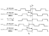
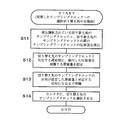
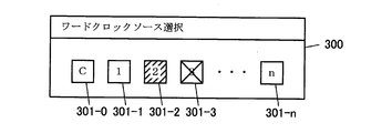
- FIG. 3 shows the hardware structural example of the digital mixer which is one Embodiment of the sound data processing apparatus of this invention. It is a figure which shows the structure of the sound signal input part shown in FIG. 1 in detail. It is a figure for demonstrating the phase adjustment of the clock signal in the sound signal input part shown in FIG. 3 is a flowchart of processing executed when the control unit of the sound signal input unit shown in FIG. 2 detects selection of a sampling clock. It is a figure which shows the example of a display of a word clock source selection screen. In a modification, it is a flow chart of processing which a control part of a sound signal input part performs regularly. In a modification, it is a flowchart of the process performed when the control part of a sound signal input part detects selection of a sampling clock. It is a figure corresponding to FIG. 2 which shows another structural example of a sound signal input part.
- FIG. 1 is a block diagram showing the configuration of the digital mixer.
- the digital mixer 10 includes a CPU 11, a ROM 12, a RAM 13, a display 14, an operator 15, a sound signal input unit 20, a signal processing unit (DSP) 21, and a sound signal output unit 22. They are connected by a bus 16.
- DSP signal processing unit
- the sound signal processing apparatus has a function of performing various signal processing on the sound signal received by the receiving unit through a plurality of signal processing channels (ch) and outputting the processed signal, and samples the sound signal received by the receiving unit.
- This is a sound data processing device that buffers and outputs in synchronization with a clock signal to be described later.
- the CPU 11 is a control means for controlling the operation of the entire digital mixer 10 and controls required hardware by executing a required program stored in the ROM 12. This allows the sound signal input unit 20 and the sound signal output unit 22 to input / output sound signals and other data, display on the display unit 14, operation detection of the operating element 15, and parameter settings according to the detected operation. Various functions such as value change and display change are realized.
- the ROM 12 is a nonvolatile storage unit that stores a control program executed by the CPU 11.
- the ROM 12 may be constituted by a flash memory which is a rewritable nonvolatile storage means.
- the RAM 13 is a storage means for storing data to be temporarily stored and used as a work memory for the CPU 11.
- the display unit 14 is a display unit that displays various information according to control by the CPU 11, and can be configured by, for example, a liquid crystal panel (LCD) or a light emitting diode (LED).
- the digital mixer 10 includes an LCD having a size capable of displaying at least the word clock source selection screen 300 shown in FIG.
- the operation element 15 is for accepting a user operation on the digital mixer 10 and can be constituted by various keys, buttons, a rotary encoder, a slider, and the like.
- a touch panel laminated on the LCD serving as the display 14 can also be used.
- the sound signal input unit 20 has at least a function of inputting digital sound data from an external device, and includes a plurality of receiving units that receive the sound data together with a word clock accompanying the sound data.
- a word clock accompanying the sound data.
- the entity of the word clock varies depending on the system.
- the sample reproduction timing is indicated by the change timing of the electric signal.
- the reproduction timing is indicated by the timing at which the packet containing the sample is received.
- numerical values indicate the sample playback timing.
- the word clock (in a broad sense) is a broader concept than the “narrow word clock” in which one clock per sample. That is, in a broad word clock, there is a case where one word clock cycle is subdivided into one sample to generate the reproduction timing (sample cycle) of each sample.
- the period of the word clock is the reproduction timing for each sample. Instead, it indicates the reproduction timing every n samples (n is an integer of 2 or more).
- n is an integer of 2 or more.
- Each sample of sound data is subjected to various signal processing required, and then at the reproduction timing indicated by the word clock (more precisely, in synchronization with the sampling clock generated from the word clock). It is converted into an analog sound signal and output.
- word clock when “word clock” is described without distinguishing between narrow sense and broad sense, this “wide sense word clock” is indicated.
- the sound signal input unit 20 inputs the word clock acquired by the receiving unit for each digital sound signal receiving unit, and includes the sampling clock S (including sampling word clock and sampling bit clock candidates) from the word clock. ) Is provided.
- the sampling word clock is a clock for reproducing the input sound signal as it is or by processing the input sound signal in units of sample periods in the DSP 21 or the like. If a 24-bit sample is played back by a DAC with a sampling frequency of 50 kHz for four channels, for example, a sampling bit clock having a frequency 128 times the sampling frequency of the sound signal is also sounded for serial transmission of the sample to the DAC. It is generated by the signal input unit 20.
- how many times the sampling bit clock frequency is set to the sampling frequency may be appropriately changed according to the purpose of use of the sampling bit clock.
- the sound signal input unit 20 has a function of inputting an analog sound signal and a word clock supplied from an external clock source in addition to a function of generating the sampling clock S, and a sampling word clock supplied to the DSP 21 and the sound signal output unit 22. A function for selecting from a plurality of candidates is provided. These functions will be described later with reference to FIG.
- the DSP 21 performs signal processing on each sample of the sound data supplied from the sound signal input unit 20 in synchronization with the sample period defined by the sampling word clock supplied from the sound signal input unit 20, and the processing A function of outputting subsequent sound data to the sound signal output unit 22 is provided.
- the signal processing in the middle of the DSP 21 or the like does not need to be strictly synchronized with the sample period, and the timing for finally converting to an analog signal by the DAC or the like is strictly synchronized with the sample period. For example, it is sufficient for quality.
- the signal processing executed by the DSP 21 is an input patch process for supplying any of a plurality of sound data supplied from the outside via the sound signal input unit 20 to a plurality of input channels.
- output channel processing for performing various channel signal processing on the output channel corresponding to the mixing bus for the sound data mixed in each mixing bus, and output sound processing after processing for each output channel as output channel It includes output processing for outputting to the output port of the associated sound signal output unit 22.
- the sound signal output unit 22 has a function of converting each sample of the sound data processed by the DSP 21 into an analog sound signal at a reproduction timing defined by the sampling clock by the internal DAC and outputting the analog sound signal to the outside. .
- the sound signal output unit 22 converts the reproduction timing indicated by the sampling word clock into a word clock by the internal transmission unit and adds it to the sound data after processing by the DSP 21, and converts the digital sound data by various transmission methods. It also has a function to send output to external equipment.
- the sampling word clock can be said to indicate “sound data sample reproduction timing”.
- various devices such as a sound generation device such as a powered speaker, a recording device, and another sound signal processing device are conceivable.
- the sound signal output unit 22 can output the sound signal via the same network that the sound signal input unit 20 uses to receive the sound signal.
- the sound signal input unit 20 receives a plurality of (in this case, n) digital sound signal receiving units 200-each receiving sound data and a word clock associated therewith via cables of various transmission methods. 1 to 200-n (The number that identifies the individual after the hyphen is called a “subscript”, and if there is no need to identify the individual thereafter, a symbol without a subscript is used. The same shall apply to the above).
- the sound signal input unit 20 receives a plurality of (m in this case) analog sound signal input units 230-1 to 230-m that receive input of analog sound signals and a word clock signal (word clock in a narrow sense). And a word clock input unit 210.
- each i-th (where 1 ⁇ i ⁇ n) sound signal receiving unit 200-i includes a carrier clock recovery unit 201-i and a data recovery unit 202-i.
- the sound signal input unit 20 includes a master PLL circuit 203-i, a FIFO 204-i, and a delay unit 206-i corresponding to each receiving unit 200.
- numbers i corresponding to the receiving units 200-i are appended to the reference numerals of these units. The same applies to sound data D, word clock W, sampling clock S before adjustment, and sampling clock Sd after adjustment, which will be described later.
- the sound signal input unit 20 also includes a control unit 205.
- the carrier clock recovery unit 201-i has a function of generating a carrier clock synchronized with each bit of the bit string signal from the waveform of the bit string signal of the transmission method input from the outside via a cable of various transmission methods.
- the carrier clock recovery unit 201-i can be configured by a PLL circuit that has good followability to the bit rate specified by the transmission method. Since the frequency stability of this PLL circuit is not so high, it cannot be used as a sampling clock as it is. Even if the carrier clock is generated by the PLL circuit for the audio transmission line, it is possible to obtain a higher quality word clock through the master PLL.
- the data recovery unit 202-i regenerates a bit string from the waveform of the bit string signal of each transmission method using the carrier clock generated by the carrier clock reproduction part 201-i, and further generates sound data Di of each sample from the bit string.
- the function to take out More specifically, the waveform of the bit string signal is latched at the timing indicated by the carrier clock, the value of each bit of the transmitted bit string is determined, and an algorithm according to the transmission method is used to determine the value of each bit from the bit string. Extract sound data.
- the transmission method uses a packet, first, a frame is extracted from the bit string based on the bit pattern of the preamble, the packet is extracted from the frame, and further, the data of the sound signal area of the packet is extracted. Sample sound data can be obtained.
- the data recovery unit 202-i is provided with a circuit such as an FPGA (Field Programmable Gate Array) for performing an extraction operation corresponding to the transmission method to be used. You may enable it to perform extraction operation according to one transmission method selected from a plurality of transmission methods. Then, the data recovery unit 202-i supplies the sound data Di extracted from the received sound signal to the corresponding FIFO 204-i. At this time, if sound data for a plurality of channels is extracted, the sound data is supplied separately for each channel. Further, the data recovery unit 202-i generates a word clock Wi indicating the reproduction timing of the sound data sample based on the reception timing of the packet including the sound data, the time stamp attached to the sound data, and the like. This is supplied to the master PLL circuit 203-i.
- a word clock Wi indicating the reproduction timing of the sound data sample based on the reception timing of the packet including the sound data, the time stamp attached to the sound data, and the like. This is supplied to the master PLL circuit 203-i.
- the master PLL circuit 203-i follows the phase of the input word clock Wi, and has a highly stable sampling word clock having the same sampling frequency as the word clock Wi, and its sampling frequency, for example, 128 A function of generating a sampling clock Si including a highly stable sampling bit clock multiplied by two is provided.
- the master PLL circuit 203-i supplies the generated sampling clock Si to the control unit 205 and the delay unit 206-i.
- the control unit 205 has a function of controlling a delay amount (phase adjustment amount) in each delay unit 206-0 to n based on a plurality of sampling clocks S supplied from each master PLL circuit 203-0 to n. This control algorithm will be described later with reference to FIGS.
- the control unit 205 also has a function of controlling the sampling clock selection in the selector 220. These operations may be realized by dedicated hardware, software, or a combination thereof.
- the delay unit 206-i delays the sampling clock Si supplied from the master PLL circuit 203-i by the delay amount set by the control unit 205 to generate the phase-adjusted sampling clock Sd-i.
- the selector 220 is provided with a function of supplying it as a candidate for the sampling clock CKo.
- the master PLL circuit 203-i and the delay unit 206-i constitute a PLL unit 207-i that generates a phase-adjusted sampling clock Sd-i based on the word clock Wi.
- the selector 220 is a clock output unit, and details thereof will be described later, but one is selected from a plurality of sampling clocks Sd supplied to the selector 220 in accordance with an instruction from the CPU 11.
- the selector 220 supplies the selected clock signal to the DSP 21 and the sound signal output unit 22 as a sampling clock CKo that defines the reproduction timing of each sample of the sound data.
- the selector 220 also supplies the sampling clock CKo to the FIFOs 204 corresponding to the receiving units 200-1 to 200-n.
- the FIFO 204-i is a buffer memory controlled by a first-in first-out (FIFO) algorithm, stores each sample of sound data sequentially input from the data recovery unit 202-i, and performs sampling in the sampling clock CKo. It has one function of a sound data output unit that outputs one sample at a time at each reproduction timing indicated by the word clock as sound data Di to the subsequent DSP 21.
- FIFO first-in first-out
- the number of samples input to the FIFO 204-i and the number of samples output from the FIFO 204-i differ within a predetermined time by the shift. Become. However, there is no particular problem as long as the buffer does not overflow or become empty. If the deviation is large enough to cause buffer overflow or sample depletion, it is preferable to mute the output of sound data from the buffer as a buffer error (output a sample having a value of zero).
- the sound data supplied to the DSP 21 is that the word clock accompanying the sound data of the sound data received from the external device is synchronized with the sampling word clock. It means that there is only sound data.
- the data recovery unit 202-i extracts sound data for a plurality of channels, the FIFO 204-i operates the buffer function for each channel.
- the waveform shaping unit 211 of the word clock input unit 210 has a function of adjusting the waveform of a word clock signal (narrowly defined word clock) input from the outside.
- the waveform shaping unit 211 can be configured by a filter or a comparator.
- the voltage inversion timing indicates the sample reproduction timing, and is handled in the same manner as the word clock W output from the data recovery unit 202.
- This word clock is referred to herein as the word clock W-0 using the subscript “0”.
- the subscript “0” is also used for the master PLL circuit 203 and the delay unit 206 corresponding to the word clock input unit 210.
- the function of the master PLL circuit 203-0 is the same as that of the other master PLL circuit 203, and generates a highly stable sampling clock S-0 from the input word clock W-0.
- the function of the delay unit 206-0 is the same as that of the other delay units 206.
- the sampling clock S-0 generated by the master PLL circuit 203-0 is delayed by a set delay amount, and the phase-adjusted sampling clock Sd-0 is generated and supplied to the selector 220.
- Each of the analog sound signal input units 230 includes an AD converter 231 and AD-converts the input analog sound signal at the timing indicated by the sampling word clock in the sampling clock CKo supplied from the selector 220.
- the obtained sound data Da is output to the DSP 21 by one sample every signal processing period in the DSP 21.
- the AD converter 231 functions as an output unit.
- the control unit 205 functions as a phase control unit, and a sampling clock Sd with a selector 220 (first clock signal selected before switching: Sd ⁇ x) is set as the sampling clock CKo.
- a switching instruction to another sampling clock Sd selected after switching, the second clock signal to be switched: Sd-y
- the sampling clock Sd ⁇ Adjust the phase of y.
- an appropriate delay amount is set for the delay unit 206-y that generates the sampling clock Sd-y before the selector 220 selects and outputs the sampling clock Sd-y according to the switching instruction.
- the PLL unit 207-x that generates the first clock signal is the first PLL unit, and the word clock Wx used to generate the first clock signal is the first word clock.
- the PLL unit 207-y that generates the second clock signal is the second PLL unit, and the word clock Wy used to generate the second clock signal is the second word clock.
- the amount of delay set by the control unit 205 in each delay unit 206 at the time before switching will be described with reference to FIG.
- the phase adjustment is performed based on the rising timing of the sampling word clock included in each sampling clock, and the waveform also shows the waveform of the sampling word clock, but other positions may be used as a reference.
- the timing is adjusted so that the sampling bit clock also rises at the rising timing of the sampling word clock. Therefore, if the phase of the sampling word clock matches, the phase of the sampling bit clock necessarily matches. Will do. As shown in FIG.
- the currently selected sampling clock Sd-x before switching is the same as the sampling clock Sx generated by the master PLL circuit 203-x, but the delay unit 206-x. Is a clock signal obtained by delaying by the delay amount Px.
- This delay amount Px is a positive value set by the control unit 205 at the previous switching, and is a delay amount for changing the rising timing of the sampling word clock from the timing Tx to a predetermined target timing Ts.
- the selector 220 selects the sampling clock Sd-x, the timing of the sampling clock CKo output from the selector 220 naturally matches the sampling clock Sd-x (see (c)).
- control unit 205 appropriately applies the delay unit 206-y so that the phase of the sampling clock Sd-y after switching to be newly selected by the selector 220 matches the phase of the sampling clock Sd-x before switching.
- the delay amount Py to be set here is a delay amount for changing the rising timing of the sampling word clock from the timing Ty of the sampling clock Sy to the timing Ts.
- This delay amount Py detects, for example, the phase difference (positive value and negative value) between the sampling clock S-x and the sampling clock Sy with respect to the sampling word clock, and the phase difference is determined as the delay amount Px. And a value within a predetermined range (corresponding to one cycle) can be selected and obtained.
- the phase difference between the sampling clock Sd-x and the sampling clock Sd-y before the delay amount change (before the current phase adjustment, that is, at the start of adjustment) is detected, and the phase difference is set to the delay amount before the change.
- the delay amount Py to be set after the change may be obtained by addition.
- control unit 205 determines the phase of the sampling clocks Sx, Sd-x, Sy, Sdy at that time, the delay amount already set in the delay units 206-x, y, and the like. An appropriate delay amount Py is obtained appropriately and set in the delay unit 206-y prior to switching.
- the sampling clock Sd-x and the sampling clock Sd-y almost completely match the phase of the sampling word clock. Accordingly, even when the clock selected by the selector 220 is switched from Sd-x to Sd-y in this state, the phase is not disturbed, and a clock having substantially the same phase as that before the switching is output as the sampling clock CKo. . That is, the switching of the word clock W used to generate the sampling clock CKo that defines the output timing of the sound data can be performed without muting the sound data to be output and without noise caused by the phase disturbance.
- FIG. 4 is a flowchart of this operation.
- the control unit 205 detects a sampling clock selection switching instruction from the CPU 11 and the sampling clock before the switching and the sampling clock after the switching have the same sampling word clock cycle, the control unit 205 proceeds to the flowchart of FIG. Start the operation shown. If the periods do not match, all sound data output from the FIFO 204 and the analog sound signal input unit 230 are once muted, the sampling clock is switched, and then the mute is released.
- the control unit 205 detects the phase difference of the sampling word clock between the sampling clock before switching that is currently selected by the selector 220 and the sampling clock that is the switching destination (S11).
- a delay amount that compensates for the phase difference detected in step S11 is set in the delay unit 206 corresponding to the subsequent sampling clock (S12).
- the control unit 205 waits until the phase becomes the corresponding phase (S13). Thereafter, the control unit 205 causes the selector 220 to select a switching destination sampling clock in accordance with the detected instruction (S14), and ends the operation of FIG. That is, the control unit 205 switches the selection of the sampling clock after the phase control of the sampling clock is completed and the phase of the sampling clock before the switching matches the phase of the sampling clock of the switching destination.
- the CPU 11 issues a sampling clock selection switching instruction to the control unit 205 based on, for example, an operation received from the user.
- This instruction can be considered as a selection switching instruction of a word clock (word clock source) used for generating a clock signal.
- FIG. 5 shows an example of a word clock source selection screen 300 for accepting the operation.
- the sampling clock Sd generated based on the word clock W supplied from which source (the receiving unit 200 or the word clock input unit 210) is used as the sampling clock CKo by the user. This is a screen for accepting selection.
- the button 301-0 corresponds to the word clock input unit 210, and the buttons 301-1 to n correspond to the receiving units 200-1 to 200-n, respectively.
- the user can select any one supply source by operating a desired button 301.
- the fact that the button 301-2 is operated is indicated by hatching.
- the control unit 205 is provided with a function of detecting frequency synchronization between the sampling clocks S supplied from each master PLL circuit 203. Furthermore, the control unit 205 may be provided with a function that requests the CPU 11 to remove the supply source of the word clock W that is the source of the unstable sampling clock S from the selection target in the word clock source selection screen 300. In response to this request, the CPU 11 performs a display (indicated here with a cross) to indicate that on the button corresponding to the supply source to be excluded from the selection target, like the button 301-3 in FIG. It is recommended that the buttons be disabled.
- the configuration of the apparatus, the display content of the screen, the specific operation procedure, the transmission method to be used, and the like are not limited to those described in the above embodiment. is there.
- the phase adjustment between the sampling clocks is performed after the sampling clock selection switching instruction is given.
- the present invention is not limited to this.
- the phase adjustment of all sampling clocks may be performed periodically.
- control unit 205 periodically executes the operation of FIG. 6 and uses the sampling clock Sd-x (or Sx) currently selected by the selector 220 and the other sampling clocks S as sampling word clocks. If the period of the sampling clock S is correct, the phase difference of the sampling word clock from the sampling clock S is detected (S21), and the delay clock 206 corresponding to the sampling clock S is sent to the sampling clock S in step S21. A delay amount for compensating the detected phase difference is set (S22).
- the operation when there is a sampling clock selection switching instruction is merely to cause the selector 220 to select the switched sampling clock Sd-y according to the instruction (S31). This is because, regardless of which sampling clock is selected, the phase adjustment between the sampling clocks before and after switching is completed by the operation of FIG. According to such a configuration, the selection switching of the sampling clock can be performed with good response.
- the CPU 11 may automatically determine which sampling clock S is to be selected by the selector 220 on some basis. For example, a sampling clock having a frequency within a predetermined range and the smallest fluctuation width is automatically selected. In the embodiment described above, it is not essential to provide the word clock input unit 210 and the analog sound signal input unit 230. Conversely, a plurality of word clock input units 210 may be provided, word clocks may be input from a plurality of external devices, and a plurality of sampling clocks generated based on the word clocks may be candidates for selection in the selector 220. Of course, the number of the digital sound signal receiving units 200 and the analog sound signal input units 230 is arbitrary.
- each sound data output unit in the above-described embodiment is configured by the FIFO 204, but may be configured by an SRC (Sampling ⁇ Rate Converter) 204 ′ as shown in FIG. Any one of these may be selectively used.
- the SRC 204′-i uses the sampling clock Si from the master PLL circuit 203-i and the sampling clock CKo to perform an interpolation operation on the sample of the sound data from the receiving unit 200-i to obtain the sound. A virtual sample of the timing of the sampling clock CKo of data is calculated.
- the sound data output unit has a FIFO 204 configuration
- the sampling word clock frequency does not match between the sampling clock Si and the sampling clock CKo
- the sound data to be supplied to the DSP 21 is prevented in order to prevent noise due to a buffer error.
- the sound data output unit has the SRC 204 ′ configuration, in principle, no buffer error occurs, so whether the sampling word clock frequency matches between the sampling clock Si and the sampling clock CKo. Regardless, sound data corresponding to the sound data from the receiver 200-i can be supplied to the DSP 21.
- the output is a sample generated by interpolation.
- the output sound data is sound data indicating (almost) the same sound as the sound indicated by the sound data extracted by the data recovery unit 202. This is referred to as outputting sound data corresponding to the received sound data.
- each sample or virtual sample of sound data is output at the reproduction timing indicated by the sampling word in the sampling clock CKo.
- the output timing may not necessarily coincide with the reproduction timing.
- the present invention also receives timing information of the digital sound signal and the accompanying word clock, generates a clock signal based on the timing information, and controls timing of signal processing and sound data output.
- the present invention can be applied to a sound signal processing apparatus used for the above. For example, it can be applied to effectors, recorders, amplifiers, synthesizers, etc., and it can receive sound signal input from the outside and supply it to a specific device or network, or a sound signal received from a specific device or network
- the present invention can also be applied to a signal output device that outputs to the outside or a powered speaker.
- the configurations and modifications described above can be applied in appropriate combinations within a consistent range.
- the switching of the word clock used for generating the clock signal that defines the output timing of the sound data is switching between the clocks that synchronize, the output It is possible to realize a sound data processing apparatus that can perform the sound data without mute and without noise caused by the phase difference.
Landscapes
- Engineering & Computer Science (AREA)
- Signal Processing (AREA)
- Computer Networks & Wireless Communication (AREA)
- Physics & Mathematics (AREA)
- Acoustics & Sound (AREA)
- Synchronisation In Digital Transmission Systems (AREA)
Abstract
【解決手段】PLL部(207-x)がワードクロック(W-x)に基づきサンプリングクロック(Sd-x)を生成し(x=0~n)、PLL部(207-y)がワードクロック(W-y)に基づきサンプリングクロック(Sd-y)(y=0~n,y≠x)を生成する。セレクタ(220)に、サンプリングクロック(Sd-x)を選択して出力している状態で出力するクロックをサンプリングクロック(Sd-y)に切り替えさせる場合に、制御部(205)が、遅延部(206-y)によりサンプリングクロック(Sd-y)の位相を調整してサンプリングクロック(Sd-x)の位相に合わせた後で、上記切り替えを行う。各デジタル音信号受信部(200)で受信した音信号のサンプルをFIFO(204)にバッファして、上記選択したサンプリングクロックに同期して出力する。
Description
この発明は、音データ処理装置及び音データ処理方法に関する。
従来から、デジタルミキサをはじめとする、デジタルの音信号(「音データ」と呼ぶ)を出力する種々の音データ処理装置において、外部の機器から音データを入力することが行われている。また、特許文献1に記載のように、複数の外部装置から、それぞれワードクロック(タイミング情報)を伴う音データを入力する装置も知られている。
特許文献1には、デジタル音響処理装置において、いずれか1つの音データ供給元を選択し、その供給元から供給されるワードクロックに基づきサンプリングクロックを生成して、その音データの出力用のクロックとしてDSP(デジタル信号処理部)へ供給する音データ処理装置が記載されている。
特許文献1には、デジタル音響処理装置において、いずれか1つの音データ供給元を選択し、その供給元から供給されるワードクロックに基づきサンプリングクロックを生成して、その音データの出力用のクロックとしてDSP(デジタル信号処理部)へ供給する音データ処理装置が記載されている。
しかしながら、特許文献1に記載のような従来の音データ処理装置では、音データの出力タイミングを規定するサンプリングクロックの生成に用いるワードクロックの選択を変更した場合、新たに選択したワードクロックから生成されるサンプリングクロックが安定するまでにある程度の時間を要するという問題があった。そしてこのため、サンプリングクロックが不安定な間は、音データの出力タイミングにゆらぎが発生してしまうため、ワードクロックの選択を変更すると、サンプリングクロックが安定するまでのある程度の時間、音データの出力をミュート(音が聞こえない程度にレベルを絞ること)しなければならなかった。
この点については、音データを受け取る入力部毎に、音データと共に伝送されるワードクロックに基づきサンプリングクロックの候補を生成するPLL(位相ロックループ)部を設け、その各候補から、音データの出力タイミングを規定するサンプリングクロックを選択するようにすれば、一定程度改善できる。この構成であれば、サンプリングクロックの候補は、選択された時点で既に安定して生成されているためである。
しかし、この構成の音データ処理装置が、相互に同期する複数のワードクロックを受け取っている場合でも、複数のPLLで生成される複数の候補間で位相は相互に一致しないことが通常である。各候補が追従するワードクロックの位相が、相互に異なるためである。このため、ユーザが候補の選択を変更すると、候補間の位相差のため、サンプリングクロックがゆらいで、出力する音データにノイズが発生する。
従って、音データの入力部毎にPLL部を設ける場合に、相互に同期する複数のワードクロックから複数の候補が生成されていても、それらの候補間で選択変更するときには、僅かな期間ではあるが音データ出力をミュートしなければならないという問題がある。なお、複数の機器のワードクロックを相互に同期させることは、プロ用の音響機器では良く行われている。その場合、それらの機器間では、音データをサンプルレート変換なしに相互に伝送できる。
従って、音データの入力部毎にPLL部を設ける場合に、相互に同期する複数のワードクロックから複数の候補が生成されていても、それらの候補間で選択変更するときには、僅かな期間ではあるが音データ出力をミュートしなければならないという問題がある。なお、複数の機器のワードクロックを相互に同期させることは、プロ用の音響機器では良く行われている。その場合、それらの機器間では、音データをサンプルレート変換なしに相互に伝送できる。
この発明は、そういう状況で、音データの出力タイミングを規定するクロック信号の生成に用いるワードクロックの切り替えを、それが同期するクロック間での切り替えである場合に、出力する音データをミュートせず、かつ、位相差に起因するノイズ無しに行えるようにすることを目的とする。
なお、サンプリングクロックは、音データ処理装置において音声データの処理タイミングをつかさどるもので、1サンプルに1クロックのサンプリングワードクロックと、たとえば128倍等それを何分周かしたサンプリングビットクロックとからなる。本明細書では、これらの両信号を示す時は「サンプリングクロック」と表記し、どちらかを示す時はそれぞれの名前で表記する。
なお、サンプリングクロックは、音データ処理装置において音声データの処理タイミングをつかさどるもので、1サンプルに1クロックのサンプリングワードクロックと、たとえば128倍等それを何分周かしたサンプリングビットクロックとからなる。本明細書では、これらの両信号を示す時は「サンプリングクロック」と表記し、どちらかを示す時はそれぞれの名前で表記する。
上記の目的を達成するため、この発明の音データ処理装置は、音データを受信する受信部と、第1ワードクロックに基づいた第1クロック信号を生成する第1PLL部と、上記第1ワードクロックに同期した第2ワードクロックに基づいた第2クロック信号を生成する第2PLL部と、上記第1クロック信号と上記第2クロック信号との位相差を検出し、その検出された位相差に応じて、上記第2クロック信号の位相を上記第1クロック信号の位相に合わせる位相制御を行う位相制御部と、まず、上記第1クロック信号を出力し、その後、切り替え指示に応じて、上記位相制御により上記第2クロック信号の位相と上記第1クロック信号の位相とが合った後で、出力するクロック信号を、上記位相制御後の上記第2クロック信号に切り替えるクロック出力部と、上記受信部で受信した音データに相当する音データを、上記クロック出力部が出力するクロック信号の示す再生タイミングに関連付けて後段に出力する音データ出力部とを設けたものである。
このような音データ処理装置において、上記位相制御部が、上記切り替え指示後に、上記位相差を検出し、その検出された位相差に応じて上記位相制御を行うとよい。
あるいは、上記位相制御部は、定期的に、上記第1クロック信号と上記第2クロック信号との位相差を検出し、その検出された位相差に応じて上記位相制御を行うとよい。
この発明は、以上のように装置として実現する他、方法、システム、プログラム、プログラムを記録した記録媒体など、任意の形態で実現可能である。
あるいは、上記位相制御部は、定期的に、上記第1クロック信号と上記第2クロック信号との位相差を検出し、その検出された位相差に応じて上記位相制御を行うとよい。
この発明は、以上のように装置として実現する他、方法、システム、プログラム、プログラムを記録した記録媒体など、任意の形態で実現可能である。
以下、この発明を実施するための形態を図面に基づいて具体的に説明する。
〔実施形態:図1乃至図5〕
まず、この発明の音データ処理装置の一実施形態であるデジタルミキサについて説明する。図1は、そのデジタルミキサの構成を示すブロック図である。
図1に示す通り、デジタルミキサ10は、CPU11、ROM12、RAM13、表示器14、操作子15、音信号入力部20、信号処理部(DSP)21、音信号出力部22を備え、これらがシステムバス16によって接続されている。そして、受信部で受信した音信号に対し、複数の信号処理チャンネル(ch)で種々の信号処理を施して出力する機能を有する音信号処理装置であり、受信部で受信した音信号のサンプルをバッファして、後述するクロック信号に同期して出力する音データ処理装置である。
〔実施形態:図1乃至図5〕
まず、この発明の音データ処理装置の一実施形態であるデジタルミキサについて説明する。図1は、そのデジタルミキサの構成を示すブロック図である。
図1に示す通り、デジタルミキサ10は、CPU11、ROM12、RAM13、表示器14、操作子15、音信号入力部20、信号処理部(DSP)21、音信号出力部22を備え、これらがシステムバス16によって接続されている。そして、受信部で受信した音信号に対し、複数の信号処理チャンネル(ch)で種々の信号処理を施して出力する機能を有する音信号処理装置であり、受信部で受信した音信号のサンプルをバッファして、後述するクロック信号に同期して出力する音データ処理装置である。
また、CPU11は、このデジタルミキサ10全体の動作を制御する制御手段であり、ROM12に記憶された所要のプログラムを実行して所要のハードウェアを制御する。そして、このことにより、音信号入力部20及び音信号出力部22における音信号及びその他のデータの入出力、表示器14における表示、操作子15の操作検出、その検出した操作に従ったパラメータの値の変更及び表示の変更、といったものをはじめとする種々の機能を実現する。
ROM12は、CPU11が実行する制御プログラム等を記憶する不揮発性記憶手段である。書き換え可能な不揮発性記憶手段であるフラッシュメモリによりROM12を構成してもよい。
RAM13は、一時的に記憶すべきデータを記憶したり、CPU11のワークメモリとして使用したりする記憶手段である。
RAM13は、一時的に記憶すべきデータを記憶したり、CPU11のワークメモリとして使用したりする記憶手段である。
表示器14は、CPU11による制御に従って種々の情報を表示する表示手段であり、例えば液晶パネル(LCD)や発光ダイオード(LED)によって構成することができる。ここで説明する例では、デジタルミキサ10は、表示器14として少なくとも図5に示すワードクロックソース選択画面300を表示可能なサイズのLCDを備える。
操作子15は、デジタルミキサ10に対するユーザ操作を受け付けるためのものであり、種々のキー、ボタン、ロータリーエンコーダ、スライダ等によって構成することができる。表示器14であるLCDに積層したタッチパネルを用いることもできる。
操作子15は、デジタルミキサ10に対するユーザ操作を受け付けるためのものであり、種々のキー、ボタン、ロータリーエンコーダ、スライダ等によって構成することができる。表示器14であるLCDに積層したタッチパネルを用いることもできる。
音信号入力部20は、少なくとも、外部の機器からデジタルの音データを入力する機能を備え、その音データをその音データに付随するワードクロックとともに受信する複数の受信部を備える。
このワードクロックは、音データの伝送方式によってフォーマットやプロシージャは異なるが、音データに付随して伝送される、その音データの各サンプルを最終的にデジタルアナログ変換器(DAC)で再生するタイミング(再生タイミング)を示すタイミング情報である。ワードクロックの実体は方式により様々であり、電気信号の変化タイミングでサンプルの再生タイミングを示す場合もあるし、サンプルを入れたパケットを受信するタイミングで再生タイミングを示す場合もあるし、タイムスタンプの数値でサンプルの再生タイミングを示す場合もある。また、この(広義の)ワードクロックは、1サンプル当たり1クロックの「狭義のワードクロック」よりも広い概念である。すなわち、広義のワードクロックにおいては、ワードクロックの1周期を1サンプル分に細分して各サンプルの再生タイミング(サンプル周期)を生成すべき場合もある。
このワードクロックは、音データの伝送方式によってフォーマットやプロシージャは異なるが、音データに付随して伝送される、その音データの各サンプルを最終的にデジタルアナログ変換器(DAC)で再生するタイミング(再生タイミング)を示すタイミング情報である。ワードクロックの実体は方式により様々であり、電気信号の変化タイミングでサンプルの再生タイミングを示す場合もあるし、サンプルを入れたパケットを受信するタイミングで再生タイミングを示す場合もあるし、タイムスタンプの数値でサンプルの再生タイミングを示す場合もある。また、この(広義の)ワードクロックは、1サンプル当たり1クロックの「狭義のワードクロック」よりも広い概念である。すなわち、広義のワードクロックにおいては、ワードクロックの1周期を1サンプル分に細分して各サンプルの再生タイミング(サンプル周期)を生成すべき場合もある。
具体的には、CobraNet(商標)やDante(商標)のように、1つのパケットに連続する複数サンプルの音データを入れて伝送する場合には、ワードクロックの周期は、各サンプル毎の再生タイミングではなく、nサンプル毎(nは2以上の整数)の再生タイミングを示すものとなる。
そして、音データの各サンプルは、必要とされる各種の信号処理が施された後、ワードクロックの示す再生タイミングで(より正確には、そのワードクロックから生成されたサンプリングクロックに同期して)アナログの音信号に変換され出力される。
本明細書において、狭義か広義かを区別せずに「ワードクロック」と述べた場合、この「広義のワードクロック」を示すものとする。
そして、音データの各サンプルは、必要とされる各種の信号処理が施された後、ワードクロックの示す再生タイミングで(より正確には、そのワードクロックから生成されたサンプリングクロックに同期して)アナログの音信号に変換され出力される。
本明細書において、狭義か広義かを区別せずに「ワードクロック」と述べた場合、この「広義のワードクロック」を示すものとする。
また、音信号入力部20は、デジタル音信号の受信部毎に、その受信部で取得されたワードクロックを入力し、そのワードクロックからサンプリングクロックS(サンプリングワードクロック及びサンプリングビットクロックの候補を含む)を生成するマスタPLL回路203を備える。
サンプリングワードクロックは、入力した音信号をそのまま、又は、入力した音信号をDSP21等においてサンプル周期単位で信号処理して再生する際のクロックである。またサンプル周波数50kHzのDACで、24ビットのサンプルを4チャンネル分再生するとすると、そのDACへのサンプルのシリアル伝送のため、たとえば、音信号のサンプル周波数の128倍の周波数を持つサンプリングビットクロックも音信号入力部20により生成される。ここで、サンプリングビットクロックの周波数をサンプル周波数の何倍とするかは、そのサンプリングビットクロックの使用目的に応じて適宜変更してよい。
サンプリングワードクロックは、入力した音信号をそのまま、又は、入力した音信号をDSP21等においてサンプル周期単位で信号処理して再生する際のクロックである。またサンプル周波数50kHzのDACで、24ビットのサンプルを4チャンネル分再生するとすると、そのDACへのサンプルのシリアル伝送のため、たとえば、音信号のサンプル周波数の128倍の周波数を持つサンプリングビットクロックも音信号入力部20により生成される。ここで、サンプリングビットクロックの周波数をサンプル周波数の何倍とするかは、そのサンプリングビットクロックの使用目的に応じて適宜変更してよい。
音信号入力部20は、サンプリングクロックSの生成機能に加え、アナログ音信号及び外部のクロック源から供給されるワードクロックを入力する機能や、DSP21及び音信号出力部22に供給するサンプリングワードクロックを複数の候補から選択する機能などを備えるが、これらの機能については図2を用いて後述する。
DSP21は、音信号入力部20から供給される音データの各サンプルに対し、同じく音信号入力部20から供給されるサンプリングワードクロックにより規定されるサンプル周期に同期して信号処理を行い、その処理後の音データを音信号出力部22へ出力する機能を備える。なお、DSP21等が行う途中の信号処理は、そのサンプル周期に厳密に同期している必要はなく、DAC等で最終的にアナログ信号に変換するタイミングが、そのサンプル周期に厳密に同期していれば、品質的にはそれで充分である。
DSP21が実行する信号処理は、例えばデジタルミキサの場合、外部から音信号入力部20を介して供給される複数の音データの何れかを複数の入力chにそれぞれ供給する入力パッチ処理、その供給された音データに対し、レベル調整、周波数特性調整、効果付与等の種々のch信号処理を行う入力ch処理、各入力chの処理後の音データを複数のミキシングバスに供給してミキシングを行うミキシング処理、各ミキシングバスでミキシングされた音データに対し、そのミキシングバスと対応する出力chにて種々のch信号処理を行う出力ch処理、および、各出力chの処理後の音データを出力chと対応付けられた音信号出力部22の出力ポートに出力する出力処理を含む。
音信号出力部22は、DSP21による処理後の音データの各サンプルを、その内部のDACにて、サンプリングクロックにより規定される再生タイミングでアナログの音信号に変換して外部へ出力する機能を備える。また、音信号出力部22は、内部の送信部にて、サンプリングワードクロックの示す再生タイミングをワードクロックに変換してDSP21による処理後の音データに付加し、各種伝送方式でデジタルの音データを外部の機器に送信出力する機能も備える。
なお、音データがデジタルのまま他機器へ送信される場合でも、その送信先の何処かで、最終的にはその付加したワードクロックの示す再生タイミングでアナログの音信号に変換される。その点を考慮すると、他機器へデジタル送信する場合でも、サンプリングワードクロックは「音データのサンプルの再生タイミングを示す」と言えるのである。また、この音データの出力先ないし送信先としては、パワードスピーカ等の発音装置や、録音装置、別の音信号処理装置など、種々のものが考えられる。オーディオネットワークを用いる場合、音信号入力部20が音信号の受信に用いたものと同じネットワークを介して音信号出力部22が音信号を出力することもできる。
以上の構成を備えるデジタルミキサ10において、特徴的な点の一つは、音信号入力部20の構成である。そこで、以下、図2を用いて音信号入力部20の構成について詳細に説明する。
図2に示すように、音信号入力部20は、各種伝送方式のケーブルを介して、それぞれ音データ及びそれに付随するワードクロックを受信する複数(ここではn個)のデジタル音信号受信部200-1~200-n(ハイフンの後ろの個体を特定する番号を「添え字」と呼び、以後、個体を特定する必要がない場合には添え字がない符号を用いる。他の添え字付きの符号についても同様とする。)を備える。また、音信号入力部20は、それぞれアナログ音信号の入力を受け付ける複数(ここではm個)のアナログ音信号入力部230-1~230-mと、ワードクロック信号(狭義のワードクロック)を受け付けるワードクロック入力部210とを備える。
図2に示すように、音信号入力部20は、各種伝送方式のケーブルを介して、それぞれ音データ及びそれに付随するワードクロックを受信する複数(ここではn個)のデジタル音信号受信部200-1~200-n(ハイフンの後ろの個体を特定する番号を「添え字」と呼び、以後、個体を特定する必要がない場合には添え字がない符号を用いる。他の添え字付きの符号についても同様とする。)を備える。また、音信号入力部20は、それぞれアナログ音信号の入力を受け付ける複数(ここではm個)のアナログ音信号入力部230-1~230-mと、ワードクロック信号(狭義のワードクロック)を受け付けるワードクロック入力部210とを備える。
これらのうち、各i番目(ただし、1≦i≦n)の音信号受信部200-iは、搬送クロック再生部201-iとデータ回復部202-iとを備える。また、音信号入力部20には、各受信部200と対応するマスタPLL回路203-i、FIFO204-i及び遅延部206-iが設けられる。図中において、これらの各部の符号には、受信部200-iと対応する番号iを添え字として付している。後述する音データD、ワードクロックW、調整前のサンプリングクロックS及び調整後のサンプリングクロックSdについても同様である。
また、音信号入力部20は、制御部205も備える。
また、音信号入力部20は、制御部205も備える。
これらのうち搬送クロック再生部201-iは、外部から各種伝送方式のケーブルを介して入力する、その伝送方式のビット列信号の波形から、ビット列信号の各ビットに同期する搬送クロックを生成する機能を備える。この搬送クロック再生部201-iは、その伝送方式で規定されるビットレートへの追従性が良いPLL回路により構成することができる。このPLL回路の周波数安定性は余り高くないので、このままではサンプリングクロックとしては使用できない。また、オーディオ伝送ライン用のPLL回路で生成される搬送クロックであっても、マスタPLLを通した方が、より品質の高いワードクロックとすることができる。
データ回復部202-iは、搬送クロック再生部201-iにより生成された搬送クロックを用いて各伝送方式のビット列信号の波形からビット列を再生し、さらにそのビット列から各サンプルの音データD-iを取り出す機能を備える。より具体的には、搬送クロックが示すタイミングでビット列信号の波形をラッチして、伝送されるビット列の各ビットの値を確定し、そのビット列から、その伝送方式に従ったアルゴリズムで、各サンプルの音データを取り出す。
例えば、オーディオ伝送ラインであれば、ビット列から所定ビット数毎に1サンプル分のビット数のデータを取り出せば、それが各サンプルの音データとなる。また、パケットを使用する伝送方式であれば、まず、ビット列からプリアンブルのビットパターンに基づいてフレームを取り出し、そのフレームからパケットを取り出し、さらに、そのパケットの音信号領域のデータを取り出すことにより、各サンプルの音データを得られる。
そして、データ回復部202-iには、使用する伝送方式に応じた取り出し動作を行うためのFPGA(Field Programmable Gate Array)等の回路を設けておく。複数の伝送方式から選択した一の伝送方式に従った取り出し動作を行えるようにしてもよい。
そして、データ回復部202-iは、受信した音信号から取り出した音データD-iを対応するFIFO204-iに供給する。このとき、複数ch分の音データを取り出していれば、ch毎に区別して音データを供給する。
また、データ回復部202-iは、音データを含むパケットの受信タイミングや音データに付されたタイムスタンプ等に基づき、音データのサンプルの再生タイミングを示すワードクロックW-iを生成して、マスタPLL回路203-iへ供給する。
そして、データ回復部202-iは、受信した音信号から取り出した音データD-iを対応するFIFO204-iに供給する。このとき、複数ch分の音データを取り出していれば、ch毎に区別して音データを供給する。
また、データ回復部202-iは、音データを含むパケットの受信タイミングや音データに付されたタイムスタンプ等に基づき、音データのサンプルの再生タイミングを示すワードクロックW-iを生成して、マスタPLL回路203-iへ供給する。
マスタPLL回路203-iは、入力されたワードクロックW-iの位相に追従し、ワードクロックW-iと同じサンプル周波数を持つ高安定度のサンプリングワードクロックと、そのサンプル周波数を、例えば、128倍に逓倍した高安定度のサンプリングビットクロックとからなるサンプリングクロックS-iを生成する機能を備える。マスタPLL回路203-iは、生成したサンプリングクロックS-iを制御部205及び遅延部206-iへ供給する。
制御部205は、各マスタPLL回路203-0~nから供給される複数のサンプリングクロックSに基づき、各遅延部206-0~nにおける遅延量(位相調整量)を制御する機能を備える。この制御のアルゴリズムについては、図3乃至図5を用いて後述する。また、制御部205は、セレクタ220におけるサンプリングクロックの選択を制御する機能も備える。これらの動作は、専用のハードウェアによって実現しても、ソフトウェアによって実現しても、その組み合わせであってもよい。
制御部205は、各マスタPLL回路203-0~nから供給される複数のサンプリングクロックSに基づき、各遅延部206-0~nにおける遅延量(位相調整量)を制御する機能を備える。この制御のアルゴリズムについては、図3乃至図5を用いて後述する。また、制御部205は、セレクタ220におけるサンプリングクロックの選択を制御する機能も備える。これらの動作は、専用のハードウェアによって実現しても、ソフトウェアによって実現しても、その組み合わせであってもよい。
遅延部206-iは、マスタPLL回路203-iから供給されるサンプリングクロックS-iを、制御部205により設定された遅延量だけ遅延して、位相調整済みのサンプリングクロックSd-iを生成し、セレクタ220へ、サンプリングクロックCKoの候補として供給する機能を備える。
マスタPLL回路203-iと遅延部206-iとが、ワードクロックW-iに基づいた位相調整済みのサンプリングクロックSd-iを生成するPLL部207-iを構成する。
マスタPLL回路203-iと遅延部206-iとが、ワードクロックW-iに基づいた位相調整済みのサンプリングクロックSd-iを生成するPLL部207-iを構成する。
なお、セレクタ220は、クロック出力部であり、詳細は後述するが、CPU11からの指示に従い、セレクタ220に供給される複数のサンプリングクロックSdの中から1つを選択する。セレクタ220は、その選択したクロック信号を、音データの各サンプルの再生タイミングを規定するサンプリングクロックCKoとして、DSP21及び音信号出力部22へ供給する。また、セレクタ220は、サンプリングクロックCKoを、各受信部200-1~200-nと対応するFIFO204へも供給する。
FIFO204-iは、ファーストイン・ファーストアウト(FIFO)のアルゴリズムで制御されるバッファメモリであり、データ回復部202-iから順次入力される音データの各サンプルを格納し、サンプリングクロックCKo中のサンプリングワードクロックの示す各再生タイミングで1サンプルずつ、音データD-iとして後段のDSP21へ出力する音データ出力部の1つの機能を備える。
なお、ワードクロックW-iと上記サンプリングワードクロックのタイミングずれがあると、そのずれ分だけ、所定時間内にFIFO204-iへ入力されるサンプル数とFIFO204-iが出力するサンプル数が異なることになる。しかし、バッファがあふれたり、空になったりしない範囲であれば特に問題はない。バッファのあふれやサンプルの枯渇が起こるほどずれが大きい場合には、バッファエラーとして当該バッファからの音データの出力をミュートする(値がゼロのサンプルを出力する)とよい。つまり、音データ出力部をFIFO204で構成した場合、DSP21に供給される音データは、外部機器から受信する音データのうちの、その音データに付随するワードクロックが、サンプリングワードクロックと同期している音データのみということである。
なお、データ回復部202-iが複数ch分の音データを取り出す場合、FIFO204-iは、バッファ機能をそのch毎に動作させる。
なお、データ回復部202-iが複数ch分の音データを取り出す場合、FIFO204-iは、バッファ機能をそのch毎に動作させる。
また、音信号入力部20において、ワードクロック入力部210の波形整形部211は、外部から入力されるワードクロック信号(狭義のワードクロック)の波形を整える機能を備える。この波形整形部211は、フィルタやコンパレータにより構成することができる。
波形を整えられたワードクロック信号は、電圧の反転タイミングがサンプルの再生タイミングを示しており、データ回復部202が出力するワードクロックWと同様に扱われる。このワードクロックは、ここでは添え字「0」を用いてワードクロックW-0と呼ぶことにする。また、ワードクロック入力部210と対応するマスタPLL回路203及び遅延部206にも添え字「0」を用いる。
マスタPLL回路203-0の機能は、他のマスタPLL回路203と同様であり、入力するワードクロックW-0から、安定度の高いサンプリングクロックS-0を生成する。遅延部206-0の機能も、他の遅延部206と同様であり、マスタPLL回路203-0が生成したサンプリングクロックS-0を設定された遅延量だけ遅延して、位相調整済みのサンプリングクロックSd-0を生成してセレクタ220へ供給する。
また、アナログ音信号入力部230は、それぞれADコンバータ231を備え、セレクタ220から供給されるサンプリングクロックCKo中のサンプリングワードクロックが示すタイミングで、入力するアナログの音信号をAD変換し、この変換で得られる音データDaを、DSP21における信号処理周期毎に1サンプルずつDSP21へ出力する。このADコンバータ231は、出力部として機能する。
次に、以上説明した音信号入力部20において制御部205が実行する、サンプリングクロックSの位相調整に関する動作について説明する。
この実施形態のデジタルミキサ10において、制御部205は、位相制御部として機能し、セレクタ220があるサンプリングクロックSd(切り替え前に選択される第1クロック信号:Sd-xとする)をサンプリングクロックCKoとして選択し出力している状態で、別のサンプリングクロックSd(切り替え後に選択される、切り替え先の第2クロック信号:Sd-yとする)への切り替え指示を検出した場合に、サンプリングクロックSd-yの位相を調整する。この調整は、その切り替え指示に応じて、セレクタ220にサンプリングクロックSd-yを選択し出力させる前に、サンプリングクロックSd-yを生成する遅延部206-yに対して適当な遅延量を設定することにより行う。
この実施形態のデジタルミキサ10において、制御部205は、位相制御部として機能し、セレクタ220があるサンプリングクロックSd(切り替え前に選択される第1クロック信号:Sd-xとする)をサンプリングクロックCKoとして選択し出力している状態で、別のサンプリングクロックSd(切り替え後に選択される、切り替え先の第2クロック信号:Sd-yとする)への切り替え指示を検出した場合に、サンプリングクロックSd-yの位相を調整する。この調整は、その切り替え指示に応じて、セレクタ220にサンプリングクロックSd-yを選択し出力させる前に、サンプリングクロックSd-yを生成する遅延部206-yに対して適当な遅延量を設定することにより行う。
なお、第1クロック信号を生成するPLL部207-xが第1PLL部であり、第1クロック信号の生成に用いるワードクロックW-xが第1ワードクロックである。第2クロック信号を生成するPLL部207-yが第2PLL部であり、第2クロック信号の生成に用いるワードクロックW-yが第2ワードクロックである。
ここで、図3を用いて、切り替え前の時点において、制御部205が各遅延部206に設定する遅延量について説明する。図3の例では、各サンプリングクロックに含まれるサンプリングワードクロックの立ち上がりタイミングを基準に位相調整を行っており、波形もサンプリングワードクロックの波形を示しているが、他の位置を基準としてもよいことはもちろんである。なお、マスタPLL回路203において、サンプリングワードクロックの立ち上がりタイミングでサンプリングビットクロックも立ち上がるようにタイミング調整がされているので、サンプリングワードクロックの位相が一致すれば、必然的にサンプリングビットクロックの位相も一致することになる。
図3に(b)で示す、現在選択されている切り替え前のサンプリングクロックSd-xは、マスタPLL回路203-xが生成した(a)に示すサンプリングクロックS-xを、遅延部206-xにて遅延量Pxだけ遅延させて得られるクロック信号である。この遅延量Pxは、前回の切り替え時に制御部205により設定された正の値であり、サンプリングワードクロックの立ち上がりタイミングを、タイミングTxから所定の目標タイミングTsに変化させるための遅延量である。
図3に(b)で示す、現在選択されている切り替え前のサンプリングクロックSd-xは、マスタPLL回路203-xが生成した(a)に示すサンプリングクロックS-xを、遅延部206-xにて遅延量Pxだけ遅延させて得られるクロック信号である。この遅延量Pxは、前回の切り替え時に制御部205により設定された正の値であり、サンプリングワードクロックの立ち上がりタイミングを、タイミングTxから所定の目標タイミングTsに変化させるための遅延量である。
また、セレクタ220は、サンプリングクロックSd-xを選択しているため、セレクタ220が出力するサンプリングクロックCKoのタイミングは、当然サンプリングクロックSd-xと一致する((c)参照)。
ここで、制御部205は、セレクタ220に新たに選択させるべき切り替え後のサンプリングクロックSd-yの位相が、切り替え前のサンプリングクロックSd-xの位相と合うように、遅延部206-yに適当な正の値の遅延量を設定して位相の調整を行う。ここで設定すべき遅延量Pyは、サンプリングワードクロックの立ち上がりタイミングを、サンプリングクロックS-yのタイミングTyからタイミングTsに変化させるための遅延量である。
この遅延量Pyは、例えば、サンプリングワードクロックに関して、サンプリングクロックS-xと、サンプリングクロックS-yとの位相差(正の値と負の値)を検出し、その位相差を、遅延量Pxに加算して、所定の範囲(1周期相当)内の値を選択して求めることができる。或いは、サンプリングクロックSd-x(=CKo)と、サンプリングクロックS-yとの位相差を、直接遅延量Pyとして求めてもよい。又は、サンプリングクロックSd-xと、遅延量変更前(今回の位相調整前、すなわち調整開始時点)のサンプリングクロックSd-yとの位相差を検出し、その位相差を、変更前の遅延量に加算して、変更後に設定すべき遅延量Pyを求めてもよい。いずれにせよ、制御部205は、その時点のサンプリングクロックS-x,Sd-x,S-y,Sd-yの位相及び、既に遅延部206-x,yに設定されている遅延量等を適宜に用いて適当な遅延量Pyを求め、切り替えに先立って、遅延部206-yに設定する。
以上の調整後には、サンプリングクロックSd-xとサンプリングクロックSd-yとではサンプリングワードクロックの位相がほぼ完全に一致する。従って、この状態でセレクタ220が選択するクロックをSd-xからSd-yに切り替えても、位相の乱れはおこらず、サンプリングクロックCKoとして、切り替え前と実質的に同じ位相のクロックが出力される。すなわち、音データの出力タイミングを規定するサンプリングクロックCKoの生成に用いるワードクロックWの切り替えを、出力する音データをミュートせず、かつ、位相の乱れに起因するノイズ無しに行うことができる。
次に、制御部205が実行するサンプリングクロックの切り替え時の動作について説明する。
図4は、この動作のフローチャートである。
制御部205は、CPU11からの、サンプリングクロックの選択切り替え指示を検出した場合に、切り替え前のサンプリングクロックと切り替え後のサンプリングクロックとでサンプリングワードクロックの周期が合っていれば、図4のフローチャートに示す動作を開始する。なお、周期が合っていない場合は、FIFO204およびアナログ音信号入力部230が出力する音データを、全て一旦ミュートしてから、サンプリングクロックの切り替えを行い、その後にそのミュートを解除する。
図4は、この動作のフローチャートである。
制御部205は、CPU11からの、サンプリングクロックの選択切り替え指示を検出した場合に、切り替え前のサンプリングクロックと切り替え後のサンプリングクロックとでサンプリングワードクロックの周期が合っていれば、図4のフローチャートに示す動作を開始する。なお、周期が合っていない場合は、FIFO204およびアナログ音信号入力部230が出力する音データを、全て一旦ミュートしてから、サンプリングクロックの切り替えを行い、その後にそのミュートを解除する。
図4の動作において、制御部205は、現在セレクタ220に選択されている切り替え前のサンプリングクロックと、切り替え先のサンプリングクロックとの間でのサンプリングワードクロックの位相差を検出し(S11)、切り替え後のサンプリングクロックと対応する遅延部206に、ステップS11で検出した位相差を補償する遅延量を設定する(S12)。これらの動作は、上述した位相調整の動作に該当するものである。また、ステップS12では、切り替え前のサンプリングクロックと対応する遅延部206の遅延量を変更してはならない。
その後、切り替え先のサンプリングクロックの位相が設定した遅延量と対応する位相になるまでに時間を要する場合には、制御部205は、その対応する位相になるまで待機する(S13)。その後、制御部205は、セレクタ220に、検出した指示に従って切り替え先のサンプリングクロックを選択させ(S14)、図4の動作を終了する。すなわち、制御部205は、サンプリングクロックの位相制御が完了し、切り替え前のサンプリングクロックの位相と切り替え先のサンプリングクロックの位相とが合った後で、サンプリングクロックの選択を切り替える。
以上の動作により、図3を用いて説明した効果を得ることができる。
以上の動作により、図3を用いて説明した効果を得ることができる。
ここで、CPU11は、例えばユーザから受け付けた操作に基づき制御部205へサンプリングクロックの選択切り替え指示を行う。この指示は、クロック信号の生成に用いるワードクロック(ワードクロックソース)の選択切り替え指示と考えることもできる。図5に、その操作を受け付けるためのワードクロックソース選択画面300の例を示す。
このワードクロックソース選択画面300は、ユーザから、どの供給源(受信部200あるいはワードクロック入力部210)から供給されるワードクロックWに基づき生成されたサンプリングクロックSdを、サンプリングクロックCKoとして用いるかの選択を受け付けるための画面である。
このワードクロックソース選択画面300は、ユーザから、どの供給源(受信部200あるいはワードクロック入力部210)から供給されるワードクロックWに基づき生成されたサンプリングクロックSdを、サンプリングクロックCKoとして用いるかの選択を受け付けるための画面である。
ボタン301-0はワードクロック入力部210と対応し、ボタン301-1~nはそれぞれ受信部200-1~nと対応する。ユーザは、所望のボタン301を操作することにより、いずれか1つの供給源を選択することができる。図5では、ボタン301-2が操作されていることを、ハッチングにより示している。
なお、図3を用いて説明した位相合わせは、安定したサンプリングクロックSが生成されていなかったり、あるいは切り替え先と切り替え前とで、サンプリングワードクロックの周波数が同期していない場合には、意味をなさない。
そこで、制御部205に、各マスタPLL回路203から供給されるサンプリングクロックS間の周波数同期を検出する機能が設けられている。さらに、制御部205に、安定しないサンプリングクロックSのもとになったワードクロックWの供給源を、ワードクロックソース選択画面300における選択対象から外すよう、CPU11に要求する機能を設けるとよい。
CPU11は、この要求に応じて、図5のボタン301-3のように、選択対象から除外する供給源と対応するボタンにその旨を示す表示(ここでは×印で示した)を行い、そのボタンを操作できないようにするとよい。
そこで、制御部205に、各マスタPLL回路203から供給されるサンプリングクロックS間の周波数同期を検出する機能が設けられている。さらに、制御部205に、安定しないサンプリングクロックSのもとになったワードクロックWの供給源を、ワードクロックソース選択画面300における選択対象から外すよう、CPU11に要求する機能を設けるとよい。
CPU11は、この要求に応じて、図5のボタン301-3のように、選択対象から除外する供給源と対応するボタンにその旨を示す表示(ここでは×印で示した)を行い、そのボタンを操作できないようにするとよい。
以上で実施形態の説明を終了するが、装置の構成、画面の表示内容、具体的な動作の手順、使用する伝送方式などが、上述の実施形態で説明したものに限られないことはもちろんである。
例えば、上述した実施形態では、サンプリングクロックの選択切り替え指示があった後で、サンプリングクロック間の位相調整を行うようにしていたが、これに限られることはない。全サンプリングクロックの位相調整を定期的に行うようにしてもよい。
例えば、上述した実施形態では、サンプリングクロックの選択切り替え指示があった後で、サンプリングクロック間の位相調整を行うようにしていたが、これに限られることはない。全サンプリングクロックの位相調整を定期的に行うようにしてもよい。
すなわち、制御部205が、定期的に図6の動作を実行し、現在セレクタ220に選択されているサンプリングクロックSd-x(又はS-x)と、他の各サンプリングクロックSとでサンプリングワードクロックの周期が合っている場合は、そのサンプリングクロックSとの間のサンプリングワードクロックの位相差を検出し(S21)、そのサンプリングクロックSと対応する遅延部206に、ステップS21で当該サンプリングクロックSについて検出した位相差を補償する遅延量を設定する(S22)。
この場合、サンプリングクロックの選択切り替え指示があった場合の動作は、図7に示すように、単に指示に従ってセレクタ220に切り替え後のサンプリングクロックSd-yを選択させる(S31)だけでよい。どのサンプリングクロックを選択する場合であっても、切り替え前と切り替え後のサンプリングクロック間の位相調整は、図6の動作で完了しているためである。
このような構成によれば、サンプリングクロックの選択切り替えを、レスポンスよく行うことができる。
このような構成によれば、サンプリングクロックの選択切り替えを、レスポンスよく行うことができる。
以上の他、セレクタ220にどのサンプリングクロックSを選択させるかを、何らかの基準でCPU11が自動的に決定してもよい。例えば、周波数が所定範囲内にありかつ揺れ幅が最も少ないサンプリングクロックを自動選択する等である。
また、上述した実施形態において、ワードクロック入力部210やアナログ音信号入力部230を設けることは必須ではない。逆に、ワードクロック入力部210を複数設け、複数の外部装置からワードクロックを入力して、それらのワードクロックに基づき生成した複数のサンプリングクロックを、セレクタ220における選択の候補としてもよい。また、デジタル音信号受信部200及びアナログ音信号入力部230の数は、もちろん任意である。
また、上述した実施形態において、ワードクロック入力部210やアナログ音信号入力部230を設けることは必須ではない。逆に、ワードクロック入力部210を複数設け、複数の外部装置からワードクロックを入力して、それらのワードクロックに基づき生成した複数のサンプリングクロックを、セレクタ220における選択の候補としてもよい。また、デジタル音信号受信部200及びアナログ音信号入力部230の数は、もちろん任意である。
また、上述した実施例における各音データ出力部はFIFO204で構成されていたが、図8に示すようにSRC(Sampling Rate Converter)204′で構成したり、または、受信部毎に、SRCとFIFOの何れか一方を選択的に使用する構成としてもよい。SRC204′-iは、マスタPLL回路203-iからのサンプリングクロックS-iと、サンプリングクロックCKoとを使用して、受信部200-iからの音データのサンプルに補間演算を施して、その音データの、サンプリングクロックCKoのタイミングの仮想的なサンプルを算出する。
音データ出力部をFIFO204構成とした場合は、サンプリングクロックS-iとサンプリングクロックCKoの間でサンプリングワードクロックの周波数が合っていなければ、バッファエラーによるノイズを防ぐため、DSP21に供給する音データをミュートせざるを得ない。それに対し、音データ出力部をSRC204′構成とした場合は、原理的にバッファエラーが生じないので、サンプリングクロックS-iとサンプリングクロックCKoの間でサンプリングワードクロックの周波数が合っているか否かに関わらず、受信部200-iからの音データに相当する音データをDSP21に供給できる。
ここで、FIFO204を用いる場合、データ回復部202が取り出した音データのサンプルは、出力タイミングを微調整された上で全て出力される。SRC204′を用いる場合、出力されるのは補間演算により生成されたサンプルである。しかし、いずれの場合も、出力される音データは、データ回復部202が取り出した音データにより示される音と(ほぼ)同じ音を示す音データである。このことを、受信した音データに相当する音データを出力する、という。またここでは、いずれの場合も音データの各サンプル又は仮想的なサンプルをサンプリングクロックCKo中のサンプリングワードが示す再生タイミングに出力している。しかし、サンプルと再生タイミングとの関連付けがなされていれば、必ずしも出力タイミングが再生タイミングと一致していなくてもよい。
また、この発明は、デジタルミキサ以外にも、それぞれデジタル音信号及びそれに付随するワードクロックのタイミング情報を受信し、そのタイミング情報に基づいたクロック信号を生成して信号処理や音データ出力のタイミング制御に用いる音信号処理装置に適用可能である。例えば、エフェクタ、レコーダ、アンプ、シンセサイザ等に適用可能であるし、外部から音信号の入力を受け付けて特定の装置あるいはネットワークに供給する信号入力装置や、特定の装置あるいはネットワークから受け取った音信号をその外部へ出力する信号出力装置やパワードスピーカにも適用可能である。
また、以上述べてきた構成及び変形例は、矛盾しない範囲で適宜組み合わせて適用することも可能である。
また、以上述べてきた構成及び変形例は、矛盾しない範囲で適宜組み合わせて適用することも可能である。
以上の説明から明らかなように、この発明によれば、音データの出力タイミングを規定するクロック信号の生成に用いるワードクロックの切り替えを、それが同期するクロック間での切り替えである場合に、出力する音データをミュートせずに、かつ、位相差に起因するノイズ無しに行うことができる音データ処理装置を実現可能である。
10:デジタルミキサ、11:CPU、12:ROM、13:RAM、14:表示器、15:操作子、16:システムバス、20:音信号入力部、21:信号処理部(DSP)、22:音信号出力部、200:デジタル音信号受信部、201:搬送クロック再生部、202:データ回復部、203:マスタPLL回路、204:FIFO、204′:SRC、205:制御部、206:遅延部、207:PLL部、210:ワードクロック入力部、211:波形整形部、220:セレクタ、230:アナログ音信号入力部、231:ADコンバータ、300:ワードクロックソース選択画面、301:ボタン、D,Da:音データ、CKo,S,Sd:サンプリングクロック(サンプリングワードクロック、サンプリングビットクロック)、W:ワードクロック
Claims (6)
- 音データを受信する受信部と、
第1ワードクロックに基づいた第1クロック信号を生成する第1PLL部と、
前記第1ワードクロックに同期した第2ワードクロックに基づいた第2クロック信号を生成する第2PLL部と、
前記第1クロック信号と前記第2クロック信号の位相差を検出し、該検出された位相差に応じて、前記第2クロック信号の位相を前記第1クロック信号の位相に合わせる位相制御を行う位相制御部と、
まず、前記第1クロック信号を出力し、その後、切り替え指示に応じて、前記位相制御により前記第2クロック信号の位相と前記第1クロック信号の位相とが合った後で、出力するクロック信号を、前記位相制御後の前記第2クロック信号に切り替えるクロック出力部と、
前記受信部で受信した音データに相当する音データを、前記クロック出力部が出力するクロック信号の示す再生タイミングに関連付けて後段に出力する音データ出力部とを備えることを特徴とする音データ処理装置。 - 請求項1に記載の音データ処理装置であって、
前記位相制御部は、前記切り替え指示後に、前記位相差を検出し、該検出された位相差に応じて前記位相制御を行うことを特徴とする音データ処理装置。 - 請求項1に記載の音データ処理装置であって、
前記位相制御部は、定期的に、前記第1クロック信号と前記第2クロック信号との位相差を検出し、該検出された位相差に応じて前記位相制御を行うことを特徴とする音データ処理装置。 - 音データを受信する受信手順と、
第1PLL部により第1ワードクロックに基づいた第1クロック信号を生成する第1生成手順と、
第2PLL部により前記第1ワードクロックに同期した第2ワードクロックに基づいた第2クロック信号を生成する第2生成手順と、
前記第1クロック信号と前記第2クロック信号との位相差を検出し、該検出された位相差に応じて、前記第2クロック信号の位相を前記第1クロック信号の位相に合わせる位相制御を行う位相制御手順と、
まず、前記第1クロック信号を出力し、その後、切り替え指示に応じて、前記位相制御により前記第2クロック信号の位相と前記第1クロック信号の位相とが合った後で、出力するクロック信号を、前記位相制御後の前記第2クロック信号に切り替えるクロック出力手順と、
前記受信手順で受信した音データに相当する音データを、前記クロック出力手順で出力するクロック信号の示す再生タイミングに関連付けて後段に出力する音データ出力手順とを備えることを特徴とする音データ処理方法。 - 請求項4に記載の音データ処理方法であって、
前記位相制御手順は、前記切り替え指示後に、前記位相差を検出し、該検出された位相差に応じて前記位相制御を行う手順であることを特徴とする音データ処理方法。 - 請求項4に記載の音データ処理方法であって、
前記位相制御手順は、定期的に、前記第1クロック信号と前記第2クロック信号との位相差を検出し、該検出された位相差に応じて前記位相制御を行う手順であることを特徴とする音データ処理方法。
Applications Claiming Priority (2)
| Application Number | Priority Date | Filing Date | Title |
|---|---|---|---|
| JP2016139217 | 2016-07-14 | ||
| JP2016-139217 | 2016-07-14 |
Publications (1)
| Publication Number | Publication Date |
|---|---|
| WO2018012576A1 true WO2018012576A1 (ja) | 2018-01-18 |
Family
ID=60953146
Family Applications (1)
| Application Number | Title | Priority Date | Filing Date |
|---|---|---|---|
| PCT/JP2017/025503 Ceased WO2018012576A1 (ja) | 2016-07-14 | 2017-07-13 | 音データ処理装置及び音データ処理方法 |
Country Status (1)
| Country | Link |
|---|---|
| WO (1) | WO2018012576A1 (ja) |
Cited By (1)
| Publication number | Priority date | Publication date | Assignee | Title |
|---|---|---|---|---|
| IT202100019751A1 (it) * | 2021-07-23 | 2023-01-23 | Monte Paschi Fiduciaria S P A | Dispositivo auricolare controllabile motorialmente per la ricetrasmissione di segnali acustici |
Citations (3)
| Publication number | Priority date | Publication date | Assignee | Title |
|---|---|---|---|---|
| JPH099399A (ja) * | 1995-06-16 | 1997-01-10 | Yamaha Corp | ディジタル音響処理装置 |
| JPH11289590A (ja) * | 1998-04-01 | 1999-10-19 | Sony Corp | オーディオデータ処理装置 |
| JP2013183403A (ja) * | 2012-03-05 | 2013-09-12 | Nec Corp | クロック位相同期化装置およびクロック位相同期化方法 |
-
2017
- 2017-07-13 WO PCT/JP2017/025503 patent/WO2018012576A1/ja not_active Ceased
Patent Citations (3)
| Publication number | Priority date | Publication date | Assignee | Title |
|---|---|---|---|---|
| JPH099399A (ja) * | 1995-06-16 | 1997-01-10 | Yamaha Corp | ディジタル音響処理装置 |
| JPH11289590A (ja) * | 1998-04-01 | 1999-10-19 | Sony Corp | オーディオデータ処理装置 |
| JP2013183403A (ja) * | 2012-03-05 | 2013-09-12 | Nec Corp | クロック位相同期化装置およびクロック位相同期化方法 |
Cited By (2)
| Publication number | Priority date | Publication date | Assignee | Title |
|---|---|---|---|---|
| IT202100019751A1 (it) * | 2021-07-23 | 2023-01-23 | Monte Paschi Fiduciaria S P A | Dispositivo auricolare controllabile motorialmente per la ricetrasmissione di segnali acustici |
| WO2023002515A1 (en) * | 2021-07-23 | 2023-01-26 | Monte Paschi Fiduciaria S.P.A. | Movement-controlled earphone device for the transceiving of acoustic signals |
Similar Documents
| Publication | Publication Date | Title |
|---|---|---|
| EP1995910B1 (en) | Synchronization of a split audio, video, or other data stream with separate sinks | |
| US11678005B2 (en) | Latency negotiation in a heterogeneous network of synchronized speakers | |
| US9753689B2 (en) | Audio processing apparatus | |
| US10191715B2 (en) | Systems and methods for audio playback | |
| GB2521264A (en) | Method for distributing a digital audio signal | |
| JP4474532B2 (ja) | 信号発生システム | |
| EP2378666A2 (en) | Digital controller for automatic rate detection and tracking of audio interface clocks | |
| CN107454510A (zh) | 蓝牙对箱的音频同步播放方法、系统 | |
| US10546581B1 (en) | Synchronization of inbound and outbound audio in a heterogeneous echo cancellation system | |
| JP2012204864A (ja) | オーディオミキシングシステム | |
| JP2008505515A (ja) | ジッタが無いサンプリングレート変換 | |
| WO2018012576A1 (ja) | 音データ処理装置及び音データ処理方法 | |
| US7738615B2 (en) | Sampling frequency conversion apparatus and signal switching apparatus | |
| JP6507749B2 (ja) | 音響信号処理装置及びプログラム | |
| JP2007256127A (ja) | レシーバ回路及びレシーバ回路試験方法 | |
| US10341213B2 (en) | Reception device and clock generating method | |
| US10999479B1 (en) | Communication device, communication system, communication method, and recording medium | |
| JP2018011216A (ja) | 音データ処理装置 | |
| JP2018029236A (ja) | 映像パケット切替装置及び方法 | |
| JP5338185B2 (ja) | 音響信号処理装置 | |
| JP2016066905A (ja) | 音響信号処理装置 | |
| JP5735360B2 (ja) | 情報端末、情報機器及びこれらからなるシステム | |
| US20250138775A1 (en) | Method and Apparatus for Control and Transfer of Audio Between Analog and Computer in Digital Audio Processing | |
| WO2024212122A1 (en) | Audio synchronization in an audio distribution system | |
| EP1559225B1 (en) | Mechanism and method for audio system synchronization |
Legal Events
| Date | Code | Title | Description |
|---|---|---|---|
| 121 | Ep: the epo has been informed by wipo that ep was designated in this application |
Ref document number: 17827699 Country of ref document: EP Kind code of ref document: A1 |
|
| NENP | Non-entry into the national phase |
Ref country code: DE |
|
| 122 | Ep: pct application non-entry in european phase |
Ref document number: 17827699 Country of ref document: EP Kind code of ref document: A1 |
|
| NENP | Non-entry into the national phase |
Ref country code: JP |