WO2018012317A1 - 信号処理装置、撮影装置、及び、信号処理方法 - Google Patents
信号処理装置、撮影装置、及び、信号処理方法 Download PDFInfo
- Publication number
- WO2018012317A1 WO2018012317A1 PCT/JP2017/024105 JP2017024105W WO2018012317A1 WO 2018012317 A1 WO2018012317 A1 WO 2018012317A1 JP 2017024105 W JP2017024105 W JP 2017024105W WO 2018012317 A1 WO2018012317 A1 WO 2018012317A1
- Authority
- WO
- WIPO (PCT)
- Prior art keywords
- image
- synthesis
- unit
- signal
- signal processing
- Prior art date
- Legal status (The legal status is an assumption and is not a legal conclusion. Google has not performed a legal analysis and makes no representation as to the accuracy of the status listed.)
- Ceased
Links
Images












Classifications
-
- H—ELECTRICITY
- H04—ELECTRIC COMMUNICATION TECHNIQUE
- H04N—PICTORIAL COMMUNICATION, e.g. TELEVISION
- H04N23/00—Cameras or camera modules comprising electronic image sensors; Control thereof
- H04N23/95—Computational photography systems, e.g. light-field imaging systems
-
- G—PHYSICS
- G03—PHOTOGRAPHY; CINEMATOGRAPHY; ANALOGOUS TECHNIQUES USING WAVES OTHER THAN OPTICAL WAVES; ELECTROGRAPHY; HOLOGRAPHY
- G03B—APPARATUS OR ARRANGEMENTS FOR TAKING PHOTOGRAPHS OR FOR PROJECTING OR VIEWING THEM; APPARATUS OR ARRANGEMENTS EMPLOYING ANALOGOUS TECHNIQUES USING WAVES OTHER THAN OPTICAL WAVES; ACCESSORIES THEREFOR
- G03B15/00—Special procedures for taking photographs; Apparatus therefor
-
- G—PHYSICS
- G03—PHOTOGRAPHY; CINEMATOGRAPHY; ANALOGOUS TECHNIQUES USING WAVES OTHER THAN OPTICAL WAVES; ELECTROGRAPHY; HOLOGRAPHY
- G03B—APPARATUS OR ARRANGEMENTS FOR TAKING PHOTOGRAPHS OR FOR PROJECTING OR VIEWING THEM; APPARATUS OR ARRANGEMENTS EMPLOYING ANALOGOUS TECHNIQUES USING WAVES OTHER THAN OPTICAL WAVES; ACCESSORIES THEREFOR
- G03B7/00—Control of exposure by setting shutters, diaphragms or filters, separately or conjointly
- G03B7/08—Control effected solely on the basis of the response, to the intensity of the light received by the camera, of a built-in light-sensitive device
- G03B7/091—Digital circuits
- G03B7/093—Digital circuits for control of exposure time
-
- H—ELECTRICITY
- H04—ELECTRIC COMMUNICATION TECHNIQUE
- H04N—PICTORIAL COMMUNICATION, e.g. TELEVISION
- H04N23/00—Cameras or camera modules comprising electronic image sensors; Control thereof
- H04N23/60—Control of cameras or camera modules
-
- H—ELECTRICITY
- H04—ELECTRIC COMMUNICATION TECHNIQUE
- H04N—PICTORIAL COMMUNICATION, e.g. TELEVISION
- H04N23/00—Cameras or camera modules comprising electronic image sensors; Control thereof
- H04N23/70—Circuitry for compensating brightness variation in the scene
-
- H—ELECTRICITY
- H04—ELECTRIC COMMUNICATION TECHNIQUE
- H04N—PICTORIAL COMMUNICATION, e.g. TELEVISION
- H04N7/00—Television systems
- H04N7/18—Closed-circuit television [CCTV] systems, i.e. systems in which the video signal is not broadcast
Definitions
- the present technology relates to a signal processing device, a photographing device, and a signal processing method, and in particular, for example, a signal processing device capable of reliably photographing a blinking photographing target in a scene having a very large luminance difference,
- the present invention relates to an imaging device and a signal processing method.
- Patent Document 1 As a countermeasure against such whiteout, for example, a technique disclosed in Patent Document 1 is known.
- the present technology has been made in view of such a situation, and makes it possible to reliably photograph a blinking photographing target in a scene having a very large luminance difference.
- a signal processing device calculates a combination coefficient indicating a combination ratio of the plurality of images based on the detection unit that detects a difference between the plurality of images captured at different exposure times.
- a signal processing apparatus comprising: a synthesis coefficient calculation unit that performs the synthesis and a synthesis unit that combines the plurality of images based on the synthesis coefficient.
- An imaging device includes an image generation unit that generates a plurality of images captured at different exposure times, a detection unit that detects a difference between the plurality of images, and the plurality of the plurality of images based on the difference.
- the image capturing apparatus includes: a synthesis coefficient calculation unit that calculates a synthesis coefficient indicating a synthesis ratio of the images; and a synthesis unit that combines the plurality of images based on the synthesis coefficient.
- a signal processing method detects a difference between a plurality of images taken at different exposure times, and calculates a combination coefficient indicating a combination ratio of the plurality of images based on the difference. And synthesizing the plurality of images based on the synthesis coefficient.
- a difference between a plurality of images captured at different exposure times is detected, and a composite ratio of the plurality of images is based on the difference. Is calculated, and the plurality of images are combined based on the combination coefficient.
- the signal processing device and the photographing device may be independent devices, or may be internal blocks constituting one device.
- FIG. 1 It is a figure which shows the structural example of a laminated
- in-vehicle cameras are increasingly installed in automobiles for the purpose of realizing advanced driving control such as automatic driving.
- advanced driving control such as automatic driving.
- it is required to ensure visibility even under conditions where the brightness difference is very large, such as at the exit of a tunnel, in order to suppress overexposure of the image and widen the dynamic range. This situation is necessary.
- FIG. 1 is a diagram illustrating an example of shooting of a shooting target with a very large luminance difference.
- FIG. 1 shows an example of photographing a tunnel exit, operation control for ensuring safety cannot be performed if the situation at the tunnel exit cannot be recognized.
- FIG. 2 is a diagram illustrating an example of shooting of a flashing shooting target.
- a traffic light whose blue (left end) is lit is shown, but the third frame (Frame 3) and the fourth frame (Frame 4).
- the traffic light in the off state is shown.
- the traffic light when the traffic light is turned off, it is a cause of hindrance to video (image) evidence when used in a drive recorder, for example.
- the traffic light when the traffic light is turned off, when the image is used for, for example, automatic driving of a car, it causes troubles in driving control such as stopping the car.
- Patent Document 1 proposes a method of suppressing an overexposure and expanding an apparent dynamic range by synthesizing images captured with a plurality of different exposure amounts.
- this method as shown in FIG. 3, the brightness value of a long exposure image (long accumulation image) having a long exposure time is referred to, and if the brightness falls below a predetermined threshold, the long exposure image (long accumulation image) If it exceeds the upper limit, it is possible to generate an image having a wide dynamic range by outputting a short exposure image (short accumulation image).
- FIG. 2 shows an example of the case where the light-off state is recorded even though the light-up state of the traffic light should be recorded.
- FIG. 5 shows an example in which shooting is performed with an exposure time that exceeds the extinguishing period of the blinking light source.
- the extinguishing period of 4 ms 4 ms ⁇ exposure time.
- the image sensor takes N times at a timing when the light source blinking cycle is divided equally into N, and after obtaining N pieces of shooting data, the average of those images is obtained. There is a method of selecting a value or a maximum value.
- FIG. 6 shows an example in which shooting is performed N times at a timing when the blinking cycle of the light source is divided into N equal parts and N pieces of shooting data are acquired.
- FIG. 6 illustrates a case where the image is shot three times at a timing obtained by dividing the blinking cycle into three equal parts with respect to the light source having the blinking cycle (Tb).
- S0, S1, and S2 indicate the exposure timings when shooting is performed three times within one frame.
- the exposure time (Tc) in each exposure is the same.
- the exposure start time of S0 is 0, the exposure timings of S0, S1, and S2 are as follows.
- S0 exposure start time 0, S0 exposure end time: 0 + Tc S1 exposure start time: Tb / 3, S1 exposure end time: Tb / 3 + Tc S2 exposure start time: (Tb / 3) ⁇ 2, S2 exposure end time: (Tb / 3) ⁇ 2 + Tc
- the technique shown in FIG. 6 is a technique based on the premise that the exposure times are the same when shooting multiple times, it is effective against the LED flicker shown in FIG.
- the effect of expanding the dynamic range of the image cannot be obtained.
- an effective exposure time can be obtained by performing exposure control so that these exposure periods are as close as possible. Extend and make it easier to capture the lighting period of fast flashing subjects.
- the maximum value of each image taking the exposure ratio into consideration is blended according to the difference amount of pixel values of the same coordinates. At that time, the motion is determined in consideration of the amount of noise.
- FIG. 7 is a block diagram illustrating a configuration example of an embodiment of a camera unit as a photographing apparatus to which the present technology is applied.
- the camera unit 10 includes a lens 101, an image sensor 102, a delay line 103, a signal processing unit 104, an output unit 105, and a timing control unit 106.
- the lens 101 collects light from the subject and makes it incident on the image sensor 102 to form an image.
- the image sensor 102 is, for example, a CMOS (Complementary Metal Metal Oxide Semiconductor) image sensor.
- the image sensor 102 receives incident light from the lens 101 and performs photoelectric conversion to capture a captured image (image data) corresponding to the incident light.
- CMOS Complementary Metal Metal Oxide Semiconductor
- the image sensor 102 functions as an imaging unit that performs imaging at an imaging timing specified by the timing control unit 106, and performs N imaging during the frame rate period of the output image output by the output unit 105. N shot images obtained by N times of shooting are sequentially output.
- the delay line 103 sequentially stores N captured images sequentially output by the image sensor 102 and supplies the N captured images to the signal processing unit 104 at the same time.
- the signal processing unit 104 processes N photographed images from the delay line 103 and generates an output image of one frame (sheet). At that time, the signal processing unit 104 blends the maximum values of the image data of the N photographed images according to the difference amount of the pixel values of the photographed images, and generates an output image.
- the signal processing unit 104 performs processing such as noise removal and WB (white balance) adjustment on the output image, and supplies the output image to the output unit 105. Further, the signal processing unit 104 detects (detects) the exposure level from the brightness of the N captured images from the delay line 103 and supplies the detected level to the timing control unit 106.
- the output unit 105 outputs an output image (video data) from the signal processing unit 104.
- the timing control unit 106 controls the shooting timing of the image sensor 102. That is, the timing control unit 106 adjusts the exposure time of the image sensor 102 based on the exposure level detected by the signal processing unit 104. At that time, the timing control unit 106 performs shutter control so that the exposure timings of the N captured images are as close as possible.
- the camera unit 10 is configured as described above.
- the image sensor 102 acquires shooting data of N shot images having different exposure times.
- the timing control unit 106 performs control to make the exposure period as close as possible to extend the effective exposure time and to easily cover the blinking cycle of a fast blinking subject such as an LED.
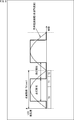
- T0, T1, and T2 indicate respective exposure timings when performing photographing three times within one frame.
- the timing control unit 106 controls the exposure timing so that the exposure of T1 is started as soon as the exposure of T0 is completed, and the exposure of T2 is started as soon as the exposure of T1 is completed. That is, the interval between the end of exposure at T0 and the start of exposure at T1 and the interval between the end of exposure at T1 and the start of exposure at T2 are minimized.
- the lighting period of the fast flashing subject can easily overlap with any one of the exposure periods T0, T1, and T2, and the probability that an image of the lighting period can be captured can be increased.
- the lighting period is short when the exposure timings of T0, T1, and T2 are set apart as shown in FIG. 9A.
- the exposure timing and the light emission timing do not overlap.
- the timing control unit 106 performs control to bring the exposure timings of T0, T1, and T2 close to each other according to the turn-off period. be able to.
- the signal processing unit 104 to be described later performs control to output the maximum values of T0, T1, and T2, when shooting a moving object having different pixel values of T0, T1, and T2, double edge There are cases where artifacts such as images may occur, but by making the exposure timings of T0, T1, and T2 close to each other, the amount of movement of the moving object can be kept small, and the effect of reducing the maximum value is also suppressed. I can expect.
- the shutter control for bringing the exposure timings of T0, T1, and T2 close to each other can be realized by using, for example, a sensor of a type that temporally overlaps the reading operation between the frames and the shutter operation.
- the following patent document 3 is disclosed as a related technique.
- Patent Document 3 Japanese Patent Application Laid-Open No. 2008-22485
- FIG. 10 is a diagram illustrating a configuration example of the signal processing unit 104 in FIG.
- the image data of N photographed images acquired by the image sensor 102 is processed and synthesized into one frame (sheet) output image. At that time, the signal processing unit 104 always performs synthesis between the image data of N photographed images so that total N-1 synthesis processes are performed.
- the captured images corresponding to T0 and T1 are also described as an image signal T0 and an image signal T1, respectively.
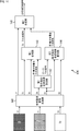
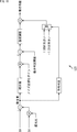
- the signal processing unit 104 includes a synthesis reference signal generation unit 121, a synthesis coefficient calculation unit 122, a motion detection unit 123, a synthesis coefficient modulation unit 124, and a synthesis unit 125.
- the synthesis reference signal generation unit 121 generates a reference signal (reference signal S0, reference signal S1) for synthesizing the image signal T0 and the image signal T1. At that time, the combined reference signal generation unit 121 generates a reference signal S0 from the image signal T0 and a reference signal S1 from the image signal T1.
- a simple luminance value can be calculated by filtering with a predetermined number of taps.
- the synthesis reference signal generation unit 121 supplies the image signal T0 and the image signal T1 to the synthesis unit 125.
- the synthesis reference signal generation unit 121 supplies the reference signal S0 to the synthesis coefficient calculation unit 122 and the motion detection unit 123, and supplies the reference signal S1 to the motion detection unit 123.
- the synthesis coefficient calculation unit 122 refers to the reference signal S0 from the synthesis reference signal generation unit 121, and calculates a synthesis coefficient for synthesizing the image signal T0 and the image signal T1.
- the synthesis coefficient calculation unit 122 supplies the synthesis coefficient to the synthesis coefficient modulation unit 124.
- the motion detection unit 123 performs motion determination by defining the difference between the reference signal S0 from the combined reference signal generation unit 121 and the reference signal S1 and the exposure ratio SGAIN1 as a motion amount. At that time, the motion detection unit 123 calculates the motion coefficient by comparing the amount of motion with the amount of noise assumed from the sensor characteristics in order to distinguish between the noise of the signal and the flashing of a fast flashing body such as an LED.
- the motion detection unit 123 divides the determination criteria for motion determination, for example, in the case of S0 ⁇ S1 and in the case of S1 ⁇ S0. Details of the motion determination in the motion detection unit 123 will be described later with reference to FIGS.
- the motion detection unit 123 supplies the motion coefficient to the synthesis coefficient modulation unit 124.
- the synthesis coefficient modulation unit 124 modulates the synthesis coefficient from the synthesis coefficient calculation unit 122 in consideration of the motion coefficient from the motion detection unit 123, and calculates a post-motion compensation synthesis coefficient. At that time, when the amount of motion is large, the synthesis coefficient modulation unit 124 synthesizes the larger one of the image signal T0 and the signal obtained by multiplying the image signal T1 by the exposure ratio SGAIN1. The synthesis coefficient modulation unit 124 supplies the motion compensated synthesis coefficient to the synthesis unit 125.
- the combining unit 125 combines (alpha blend) the image signal T0 and the image signal T1 from the combination reference signal generation unit 121 with the post-motion-compensated combination coefficient from the combination coefficient modulation unit 124, and obtains HDR (High Dynamic Range) Outputs a combined image signal as a combined signal.
- HDR High Dynamic Range
- the signal processing unit 104 is configured as described above.
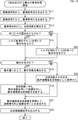
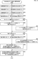
- step S11 the composite reference signal generation unit 121 generates a reference signal S0 from the image signal T0 input thereto.
- step S12 the composite reference signal generation unit 121 generates a reference signal S1 from the image signal T1 input thereto.
- step S13 the synthesis coefficient calculation unit 122 calculates a synthesis coefficient from the reference signal S0 obtained by the process in step S11.
- step S14 the motion detection unit 123 determines whether or not the relationship of S0 ⁇ S1 ⁇ S1 exposure ratio is satisfied.
- step S14 If it is determined in step S14 that the relationship of S0 ⁇ S1 ⁇ S1 exposure ratio is satisfied, the process proceeds to step S15.
- step S ⁇ b> 15 the motion detection unit 123 performs motion determination using the noise normalization gain 1.
- step S14 determines whether the relationship of S0 ⁇ S1 ⁇ S1 exposure ratio is satisfied, that is, the relationship of S0 ⁇ S1 ⁇ S1 exposure ratio is established.
- step S16 the motion detection unit 123 performs motion determination using the noise normalization gain 0.
- step S15 or S16 the process proceeds to step S17.
- step S17 the motion detection unit 123 determines whether or not there is a motion based on the result of the motion determination obtained in the process of step S15 or S16.
- step S17 If it is determined in step S17 that there is a movement, the process proceeds to step S18.
- step S18 the motion detection unit 123 calculates a motion coefficient according to the amount of motion obtained by the processing in step S15 or S16.
- steps S14 to S18 executed by the motion detection unit 123 will be described later with reference to FIG. 19, but the noise normalization gain (0, 1) corresponding to the sign of the motion evaluation value and the exposure ratio.
- the motion detection accuracy can be improved by performing the motion determination process after multiplying by.
- step S19 the synthesis coefficient modulation unit 124 modulates the synthesis coefficient obtained in step S13 using the motion coefficient obtained in step S18, and generates a motion compensated synthesis coefficient.
- step S17 determines whether there is no movement. If it is determined in step S17 that there is no movement, the process proceeds to step S20.
- step S20 the synthesis coefficient modulation unit 124 uses the synthesis coefficient obtained in the process of step S13 as it is as a post-motion compensation synthesis coefficient.
- step S19 or S20 When the post-motion compensation composite coefficient is obtained in the process of step S19 or S20, the process proceeds to step S21.
- step S21 the synthesizer 125 synthesizes the image signal T0 and the image signal T1 with reference to the motion-compensated synthesis coefficient obtained in the process of step S19 or S20.
- step S22 the synthesis unit 125 outputs the post-combination image signal obtained by the process in step S21.
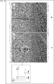
- FIG. 12 shows the processing result of the signal processing for the captured image showing the LED traffic light.
- FIG. 12A shows the processing result when the conventional method is used, and compares it with the processing result when the method of the present technology of FIG. 12B is used.
- the signal is displayed in a state where the lighting state of the LED traffic light is recorded only in the long accumulation image (image signal T0) and the pixel value of the long accumulation (T0) is saturated. If the pixel value exceeding the long accumulation (T0) saturation level is replaced with the short accumulation (T1) in order to expand the dynamic range, the LED traffic light is turned off for the short accumulation image (image signal T1) The signal after replacement will also turn off.
- FIG. 13 shows the processing result of the signal processing for the photographed image on which the LED speed restriction sign is reflected.
- FIG. 13A shows the processing result when the conventional method is used, and compares it with the processing result when the method of the present technology of FIG. 13B is used.
- the lighting state of the LED speed regulation sign is recorded only in the long accumulation image (image signal T0), and the pixel value of the long accumulation (T0) is saturated.
- the LED speed regulation indicator will turn off in the short accumulation image (image signal T1) Therefore, the signal after the replacement is also turned off.
- FIG. 14 is a diagram illustrating a configuration example of the signal processing unit 104 when three sheets are combined.
- the exposure ratio gain for adjusting the brightness of T1 to T0 is defined as SGAIN1, and the exposure ratio gain for adjusting the brightness of T2 to T0 is defined as SGAIN2.
- the captured images corresponding to T0, T1, and T2 are also described as an image signal T0, an image signal T1, and an image signal T2, respectively.
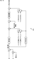
- the signal processing unit 104 includes a synthesis reference signal generation unit 141, a first motion detection / synthesis coefficient calculation unit 142, a first synthesis unit 143, a second motion detection / synthesis coefficient calculation unit 144, and a second synthesis unit. 145.
- the synthesis reference signal generation unit 141 generates a reference signal (reference signal S0, reference signal S1, reference signal S2) for synthesizing the image signal T0, the image signal T1, and the image signal T2. At that time, the combined reference signal generation unit 141 generates a reference signal S0 from the image signal T0, a reference signal S1 from the image signal T1, and a reference signal S2 from the image signal T2.
- a generation method of the reference signals S0, S1, and S2 serving as a reference for example, a simple luminance value can be calculated by filtering with a predetermined number of taps.
- the synthesis reference signal generation unit 141 supplies the image signal T0 and the image signal T1 to the first synthesis unit 143, and supplies the image signal T2 to the second synthesis unit 145.
- the synthesized reference signal generation unit 141 supplies the reference signal S0 and the reference signal S1 to the first motion detection / synthesis coefficient calculation unit 142, and the reference signal S1 and the reference signal S2 are calculated as the second motion detection / synthesis coefficient. To the unit 144.
- the first motion detection / synthesis coefficient calculation unit 142 calculates a first synthesis coefficient for synthesizing the image signal T0 and the image signal T1 with reference to the reference signal S0 from the synthesis reference signal generation unit 141.
- the first motion detection / synthesis coefficient calculation unit 142 defines a difference between the reference signal S0 from the synthesis reference signal generation unit 141 and a signal obtained by multiplying S1 by the exposure ratio SGAIN1 as a first motion amount. Make a decision.
- the first motion detection / synthesis coefficient calculation unit 142 compares the first motion amount with the noise amount assumed from the sensor characteristics in order to distinguish between the noise of the signal and the flashing of the fast flashing body such as the LED. A first motion coefficient is calculated. However, when performing motion determination, for example, the determination criterion for motion determination is divided between S0 ⁇ S1 and S1 ⁇ S0. Details of the motion determination in the first motion detection / synthesis coefficient calculation unit 142 will be described later with reference to FIGS. 18 and 19.
- the first motion detection / synthesis coefficient calculation unit 142 performs modulation by adding the first motion coefficient to the first synthesis coefficient, and calculates the first motion-compensated synthesis coefficient. At that time, when the amount of motion is large, the first motion detection / synthesis coefficient calculation unit 142 synthesizes the larger one of the image signal T0 and the signal obtained by multiplying the image signal T1 by the exposure ratio SGAIN1. So that The first motion detection / synthesis coefficient calculation unit 142 supplies the first motion-compensated synthesis coefficient to the first synthesis unit 143.
- the first motion detection / synthesis coefficient calculation unit 142 synthesizes (alpha blends) the reference signal S0 and the reference signal S1 with reference to the first motion compensated synthesis coefficient, and S0-S1 obtained as a result thereof.
- the synthesized signal is supplied to the second motion detection / synthesis coefficient calculation unit 144.
- the first synthesis unit 143 synthesizes (alpha blends) the image signal T0 and the image signal T1 from the synthesis reference signal generation unit 141 with the first motion-compensated synthesis coefficient from the first motion detection / synthesis coefficient calculation unit 142. Then, the resultant T0-T1 combined signal is supplied to the second combining unit 145.
- the second motion detection / synthesis coefficient calculation unit 144 refers to the reference signal S1 from the synthesis reference signal generation unit 141, and calculates a second synthesis coefficient for synthesizing the T0-T1 synthesis signal and the image signal T2. Further, the second motion detection / combination coefficient calculation unit 144 performs motion determination by defining a difference between the S0-S1 composite signal and a signal obtained by multiplying S2 by the exposure ratio SGAIN2 as a second motion amount.
- the second motion detection / synthesis coefficient calculation unit 144 compares the second motion amount with the noise amount assumed from the sensor characteristics in order to distinguish between the noise of the signal and the blinking of the fast blinking body such as the LED. A second motion coefficient is calculated. However, when performing motion determination, for example, the determination criterion for motion determination is divided between the case where S0-S1 composite signal ⁇ S2 and the case where S2 ⁇ S0-S1 composite signal. Details of the motion determination in the second motion detection / synthesis coefficient calculation unit 144 will be described later with reference to FIGS. 18 and 19.
- the second motion detection / synthesis coefficient calculation unit 144 performs modulation by adding the second motion coefficient to the second synthesis coefficient, and calculates a second motion-compensated synthesis coefficient. At that time, when the amount of motion is large, the second motion detection / composition coefficient calculation unit 144 has a larger one of the T0-T1 composite signal and the signal obtained by multiplying the image signal T2 by the exposure ratio SGAIN2. To be synthesized. The second motion detection / synthesis coefficient calculation unit 144 supplies the second motion compensated synthesis coefficient to the second synthesis unit 145.
- the second synthesis unit 145 uses the T0-T1 synthesized signal from the first synthesis unit 143 and the image signal T2 from the synthesis reference signal generation unit 141 as the second motion from the second motion detection / synthesis coefficient calculation unit 144.
- a composite (alpha blend) is performed with the post-compensation composite coefficient, and a composite image signal is output as a post-HDR composite signal obtained as a result.
- the light source lighting state is recorded with a short exposure time compared to the first-stage synthesis in which the T0-T1 signal is blended by separating into two-stage synthesis.
- the second-stage synthesis that blends T2 signals that are highly unlikely, it is possible to make adjustments such as lowering the intensity to which this correction is applied, and an effect of suppressing adverse effects is expected.
- step S51 the composite reference signal generation unit 141 generates a reference signal S0 from the image signal T0 input thereto.
- step S52 the combined reference signal generation unit 141 generates the reference signal S1 from the image signal T1 input thereto.
- step S53 the composite reference signal generation unit 141 generates a reference signal S2 from the image signal T2 input thereto.
- step S54 the first motion detection / synthesis coefficient calculation unit 142 calculates a first synthesis coefficient from the reference signal S0 obtained in the process of step S51.
- step S55 the first motion detection / synthesis coefficient calculation unit 142 determines whether or not the relationship of S0S ⁇ S1 ⁇ S1 exposure ratio is satisfied.
- step S55 If it is determined in step S55 that the relationship of S0 ⁇ S1 ⁇ S1 exposure ratio is satisfied, the process proceeds to step S56.
- step S ⁇ b> 56 the first motion detection / synthesis coefficient calculation unit 142 performs motion determination using the noise normalization gain 1.
- step S55 if it is determined in step S55 that the relationship of S0 ⁇ S1 ⁇ S1 exposure ratio is not satisfied, that is, the relationship of S0 ⁇ S1 ⁇ S1 exposure ratio is established, the process proceeds to step S57.
- step S57 the first motion detection / synthesis coefficient calculation unit 142 performs motion determination using the noise normalization gain 0.
- step S58 the first motion detection / synthesis coefficient calculation unit 142 determines whether there is a motion based on the result of the motion determination obtained in the process of step S56 or S57.
- step S58 If it is determined in step S58 that there is a movement, the process proceeds to step S59.
- step S59 the first motion detection / synthesis coefficient calculation unit 142 calculates the first motion coefficient according to the motion amount obtained in the process of step S56 or S57.
- step S60 the first motion detection / synthesis coefficient calculation unit 142 modulates the first synthesis coefficient obtained by the process of step S54 using the first motion coefficient obtained by the process of step S59. A motion compensation post-synthesis coefficient is generated.
- step S58 determines whether there is no movement. If it is determined in step S58 that there is no movement, the process proceeds to step S61.
- step S61 the first motion detection / synthesis coefficient calculation unit 142 uses the first synthesis coefficient obtained in step S54 as it is as the first motion-compensated synthesis coefficient.
- step S60 When the first motion-compensated synthesis coefficient is obtained in the process of step S60 or S61, the process proceeds to step S62.
- step S62 the first motion detection / synthesis coefficient calculation unit 142 refers to the first motion-compensated synthesis coefficient obtained in the process of step S60 or S61, and synthesizes the reference signal S0 and the reference signal S1. -S1 composite signal is generated.
- step S63 the first synthesis unit 143 synthesizes the image signal T0 and the image signal T1 with reference to the first motion-compensated synthesis coefficient obtained in the process of step S60 or S61, and generates a T0-T1 synthesized signal. Generate.
- step S64 the second motion detection / synthesis coefficient calculation unit 144 calculates a second synthesis coefficient from the reference signal S1 obtained in the process of step S52.
- step S65 the second motion detection / combination coefficient calculation unit 144 determines whether or not the relationship of S0-S1 composite signal ⁇ S2 ⁇ S2 exposure ratio is satisfied.
- step S65 If it is determined in step S65 that the S0-S1 composite signal ⁇ S2 ⁇ S2 exposure ratio is satisfied, the process proceeds to step S66.
- step S ⁇ b> 66 the second motion detection / synthesis coefficient calculation unit 144 performs motion determination using the noise normalization gain 2.
- step S65 if it is determined in step S65 that the relationship of S0-S1 composite signal ⁇ S2 ⁇ S2 exposure ratio is not satisfied, that is, the relationship of S0-S1 composite signal ⁇ S2 ⁇ S2 exposure ratio is satisfied, The process proceeds to step S67.
- step S ⁇ b> 67 the second motion detection / synthesis coefficient calculation unit 144 performs motion determination using the noise normalization gain 1.
- step S68 the second motion detection / synthesis coefficient calculation unit 144 determines whether or not there is a motion based on the result of the motion determination obtained in the process of step S66 or S67.
- step S68 If it is determined in step S68 that there is a movement, the process proceeds to step S69.
- step S69 the second motion detection / synthesis coefficient calculation unit 144 calculates the second motion coefficient in accordance with the amount of motion obtained in the process of step S66 or S67.
- step S70 the second motion detection / synthesis coefficient calculation unit 144 modulates the second synthesis coefficient obtained by the process of step S64 using the second motion coefficient obtained by the process of step S69. A motion compensation post-synthesis coefficient is generated.
- step S68 determines whether there is no movement. If it is determined in step S68 that there is no movement, the process proceeds to step S71.
- step S71 the second motion detection / synthesis coefficient calculation unit 144 uses the second synthesis coefficient obtained in the process of step S64 as it is as the second motion-compensated synthesis coefficient.
- step S70 When the second motion-compensated synthesis coefficient is obtained in the process of step S70 or S71, the process proceeds to step S72.
- step S72 the second synthesizing unit 145 synthesizes the T0-T1 synthesized signal and the image signal T2 with reference to the second motion-compensated synthesis coefficient obtained in the process of step S70 or S71.
- step S73 the second synthesis unit 145 outputs the synthesized image signal obtained by the process in step S72.
- FIG. 17 is a diagram illustrating another configuration example of the signal processing unit 104 when three sheets are combined.
- the combination is performed twice, and the motion detection is performed each time.
- the signal processing unit 104 in FIG. 17 performs the synthesis in two steps in the same way as in FIG. 14, but does not perform motion detection when synthesizing, and applies the T0-T1-T2 synthesized signal first. To generate. In parallel with the processing, the signal processing unit 104 in FIG. 17 adds processing for selecting the maximum value of the three captured images and processing for performing motion detection on the three captured images, and adds motion information. It is characterized in that the maximum value of T0-T1-T2 is synthesized at the final stage with respect to the T0-T1-T2 synthesized signal not taken into account.
- the signal processing unit 104 includes a synthesis reference signal generation unit 161, a first synthesis coefficient calculation unit 162, a second synthesis coefficient calculation unit 163, a motion detection / synthesis coefficient calculation unit 164, a maximum value selection unit 165, and a first value selection unit 165. It comprises a synthesis unit 166, a second synthesis unit 167, and a third synthesis unit 168.
- the combined reference signal generation unit 161 generates a reference signal (reference signal S0, reference signal S1, reference signal S2) for combining the image signal T0, the image signal T1, and the image signal T2. At that time, the synthesized reference signal generation unit 161 generates the reference signal S0 from the image signal T0, the reference signal S1 from the image signal T1, and the reference signal S2 from the image signal T2.
- the synthesis reference signal generation unit 161 supplies the image signal T0 and the image signal T1 to the first synthesis unit 166, and supplies the image signal T2 to the second synthesis unit 167. In addition, the synthesis reference signal generation unit 161 supplies the image signal T0 to the image signal T2 to the maximum value selection unit 165.
- the synthesis reference signal generation unit 161 supplies the reference signal S0 to the first synthesis coefficient calculation unit 162, and supplies the reference signal S1 to the second synthesis coefficient calculation unit 163.
- the combined reference signal generation unit 161 supplies the reference signal S0 to the reference signal S2 to the motion detection / synthesis coefficient calculation unit 164.
- the first synthesis coefficient calculation unit 162 calculates a first synthesis coefficient for synthesizing the image signal T0 and the image signal T1 with reference to the reference signal S0 from the synthesis reference signal generation unit 161, and the first synthesis unit 166. To supply.
- the second synthesis coefficient calculation unit 163 refers to the reference signal S1 from the synthesis reference signal generation unit 161, calculates a second synthesis coefficient for synthesizing the T0-T1 synthesis signal and the image signal T2, and performs the second synthesis. To the unit 167.
- the motion detection / synthesis coefficient calculation unit 164 performs motion determination based on the reference signal S0 to the reference signal S2 from the synthesis reference signal generation unit 161, and calculates a post-motion compensation synthesis coefficient according to the result of the motion determination. , And supplied to the third synthesis unit 168.
- the first synthesis unit 166 synthesizes (alpha blends) the image signal T0 and the image signal T1 from the synthesis reference signal generation unit 161 with the first synthesis coefficient from the first synthesis coefficient calculation unit 162, and obtains the result.
- the T0-T1 combined signal is supplied to the second combining unit 167.
- the second synthesis unit 167 synthesizes the T0-T1 synthesized signal from the first synthesis unit 166 and the image signal T2 from the synthesis reference signal generation unit 161 with the second synthesis coefficient from the second synthesis coefficient calculation unit 163. (Alpha blending), and the resultant T0-T1-T2 composite signal is supplied to the third synthesis unit 168.
- the maximum value selection unit 165 selects the maximum value of the three captured images based on the image signal T0 to the image signal T2 from the synthesis reference signal generation unit 161, and sets the T0-T1-T2 maximum value obtained as a result. , And supplied to the third synthesis unit 168.
- the third synthesis unit 168 outputs the T0-T1-T2 maximum value from the maximum value selection unit 165 to the T0-T1-T2 synthesis signal from the second synthesis unit 167 from the motion detection / synthesis coefficient calculation unit 164.
- the synthesized image signal is output as an HDR synthesized signal obtained as a result of synthesis (alpha blending) using the motion compensated synthesis coefficient.
- FIG. 18 is a diagram illustrating a modification of the motion detection process performed by the motion detection unit 123 in FIG. 10 and the first motion detection / synthesis coefficient calculation unit 142 in FIG.
- the difference signal between long accumulation (S0) and intermediate accumulation (S1) ⁇ exposure ratio gain (long accumulation exposure time (T0) ⁇ intermediate accumulation exposure time (T1)) is a noise level.
- an evaluation value representing how many times the difference signal is noise is generated by multiplying the difference signal by a normalization gain.
- the noise normalization gain is calculated in consideration of the gain applied to the input signal (for example, AGC (Automatic ⁇ ⁇ ⁇ Gain Control), calibration gain, level balance gain, exposure ratio gain, etc.) for each color.
- the noise normalization gain is not set appropriately and the amount of motion is excessive with respect to the correct value, the image noise is erroneously determined to be motion, resulting in noise being output and image quality degradation. Will occur. Also, for example, if the noise normalization gain is not set appropriately and the amount of movement is too small relative to the correct value, the lighting state is output correctly by misjudging the blinking of the LED as noise. I can't do anything. Therefore, an appropriate noise normalization gain is set in the motion detection process of FIG.
- FIG. 19 is a diagram illustrating another modified example of the motion detection process performed by the motion detection unit 123 in FIG. 10, the first motion detection / synthesis coefficient calculation unit 142 in FIG. 14, and the like.
- 1.0 can be set as the noise normalization gain 1
- the reciprocal of the exposure ratio can be set as the noise normalization gain 2, for example.
- the motion determination threshold can be made common regardless of the sign of the motion amount, and noise is generated. It is possible to suppress the adverse effect of the maximum value such as missing.
- the noise normalization gain 0 is selected and the motion determination is performed.
- noise normalization gain 1 is selected and motion determination is performed (S56 in FIG. 15).
- the noise normalization gain 1 is selected.
- noise normalization gain 2 is selected and motion determination is performed. (S66 in FIG. 16).
- the noise normalization gain 1 selected by the first motion detection / synthesis coefficient calculation unit 142 (S56 in FIG. 15) and the noise normalization gain 1 selected by the second motion detection / synthesis coefficient calculation unit 144 (FIG. 15). 16 (S67) are set to the same value, and three noise normalization gains are used in the two-stage motion determination. Then, by multiplying the sign of the motion evaluation value by the noise normalization gain corresponding to the exposure ratio and then performing the motion determination process, the accuracy of motion detection can be improved.
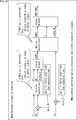
- FIG. 20 shows signal processing when three photographed images (L, M, S) are combined into one output image.
- motion detection processing and synthesis processing (alpha blending) are performed in two stages.
- FIG. 21 three types of exposure (L: Long Exposure, M: Medium Exposure, S: Short Exposure) where the vertical axis is Linearized signal [LSB] and the horizontal axis is Illuminance [lux]. And the gain (Gain_M, Gain_S).
- L, M, S three captured images
- long accumulation corresponds to T0
- intermediate storage M: Medium Exposure
- short storage S: Short Exposure
- the long accumulation image (L) is a long exposure image and corresponds to the image of the image signal T0 described above.
- the intermediate accumulation image (M) corresponds to an image of the image signal T1 that is a medium time exposure image
- the short accumulation image corresponds to an image of the image signal T2 that is a short exposure image.
- “Motion ⁇ Detection1 ”,“ Alpha Blend1 ”,“ Motion Detection2 ”, and“ Alpha Blend2 ” are, for example, the first motion detection / synthesis coefficient calculation unit 142 and the first synthesis unit shown in FIG. 143, a second motion detection / synthesis coefficient calculation unit 144, and a second synthesis unit 145, respectively. That is, in FIG. 20, “alpha_L” corresponds to the first motion-compensated synthesis coefficient, and “alpha_M” corresponds to the second motion-compensated synthesis coefficient. “HDR1” corresponds to a T0-T1 combined signal (S0-S1 combined signal), and “HDR_OUT” corresponds to a combined image signal.
- the lighting state of the light source is recorded only in the long accumulation image (L), and the lighting state of the light source is recorded in the middle accumulation image (M) and the short accumulation image (S).
- the following processing is performed in the signal processing of the present technology. That is, in the signal processing of the present technology, for example, a long accumulation image and a middle accumulation image are obtained by taking a difference signal between a long accumulation image signal (Level (of (L) and a middle accumulation image signal (Level of M). Which of the lighting states of the light source is included is determined, and the synthesis coefficient (blend rate) is changed according to the specified result.
- the signal of the long accumulation image is larger among the signal of the long accumulation image and the signal of the medium accumulation image (when the light source is included in the long accumulation image).
- the composition ratio (blend ratio) of the signal of the long accumulation image is increased.
- the intermediate storage image when the signal of the intermediate storage image is larger among the signal of the long storage image and the signal of the intermediate storage image (when the light source is included in the intermediate storage image), the intermediate storage image Increase the signal synthesis ratio (blend rate).
- step S60 in FIG. 20 is executed by the first motion detection / combination coefficient calculation unit 142 (“MotionionDetection1” in FIG. 20), for example, in the process of step S60 in FIG. It will correspond to.
- the long accumulation image signal is larger than the long accumulation image signal and the medium accumulation image signal (the light accumulation is included in the long accumulation image).
- the composite ratio of the stored image signal is increased, and the first motion compensated composite coefficient is obtained.
- the lighting of fast flashing subjects such as LEDs while maintaining visibility from bright to dark areas It is possible to realize a recording device capable of recording without missing the state.
- the present technology can be applied to all photographing apparatuses such as in-vehicle cameras and surveillance cameras.
- the subject to be photographed is not limited to the LED traffic light or the LED speed regulation sign, and the subject to be photographed can be a subject having a very large luminance difference or a blinking subject (for example, a light-emitting body that blinks rapidly).
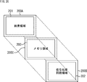
- the camera unit 10 shown in FIG. 7 can be configured as a stacked solid-state imaging device such as a back-illuminated CMOS image sensor.
- a semiconductor substrate 200 ⁇ / b> A in which the pixel region 201 is formed and a semiconductor substrate 200 ⁇ / b> B in which the signal processing circuit region 202 is formed can be stacked.
- the semiconductor substrate 200A and the semiconductor substrate 200B are electrically connected by, for example, a through via or a metal bond.
- the signal processing circuit area 202 includes a camera signal processing unit 211, signal processing units 212 to 214 that perform various signal processing, and the like.
- the camera signal processing unit 211 can be configured to include the signal processing unit 104 (FIG. 7) described above. That is, the camera signal processing unit 211 can perform the signal processing shown in the flowcharts of FIGS. 11 and 15 and 16.
- the camera signal processing unit 211 may include the delay line 103, the timing control unit 106, and the like.
- the pixel area 201 includes a pixel array portion of the image sensor 102 and the like.
- a semiconductor substrate 200C in which a memory region 203 is formed is stacked between a semiconductor substrate 200A in which a pixel region 201 is formed and a semiconductor substrate 200B in which a signal processing circuit region 202 is formed. You may be made to do.
- the signal processing circuit area 202 includes a camera signal processing unit 311 and signal processing units 312 to 314 that perform various signal processing.
- the memory area 203 includes memory units 321 to 322.
- the camera signal processing unit 311 includes the signal processing unit 104 (FIG. 7) and the like, similar to the camera signal processing unit 211 of FIG. Note that the delay line 103 is included in the memory area 203 so that the delay line 103 sequentially stores image data from the pixel area 201 (imaging device 102), and the camera signal processing unit 311 (signal processing unit) is appropriately stored. 104).
- the above-described series of processing can be executed by hardware or can be executed by software.
- a program constituting the software is installed in the computer.
- the computer includes, for example, a general-purpose personal computer capable of executing various functions by installing a computer incorporated in dedicated hardware and various programs.
- FIG. 28 is a block diagram illustrating a configuration example of hardware of a computer that executes the above-described series of processes by a program.
- a CPU Central Processing Unit
- ROM Read Only Memory
- RAM Random Access Memory
- An input / output interface 1005 is further connected to the bus 1004.
- An input unit 1006, an output unit 1007, a recording unit 1008, a communication unit 1009, and a drive 1010 are connected to the input / output interface 1005.
- the input unit 1006 includes a keyboard, a mouse, a microphone, and the like.
- the output unit 1007 includes a display, a speaker, and the like.
- the recording unit 1008 includes a hard disk, a nonvolatile memory, and the like.
- the communication unit 1009 includes a network interface.
- the drive 1010 drives a removable recording medium 1011 such as a magnetic disk, an optical disk, a magneto-optical disk, or a semiconductor memory.
- the CPU 1001 loads the program stored in the recording unit 1008 into the RAM 1003 via the input / output interface 1005 and the bus 1004 and executes the program, for example. A series of processing is performed.
- the program executed by the computer 1000 can be provided by being recorded on a removable recording medium 1011 as a package medium, for example.
- the program can be provided via a wired or wireless transmission medium such as a local area network, the Internet, or digital satellite broadcasting.
- the program can be installed in the recording unit 1008 via the input / output interface 1005 by attaching the removable recording medium 1011 to the drive 1010.
- the program can be received by the communication unit 1009 via a wired or wireless transmission medium and installed in the recording unit 1008.
- the program can be installed in the ROM 1002 or the recording unit 1008 in advance.
- the program executed by the computer 1000 may be a program that is processed in time series in the order described in this specification, or a necessary timing such as when a call is made in parallel. It may be a program in which processing is performed.
- processing steps for describing a program for causing the computer 1000 to perform various processes do not necessarily have to be processed in chronological order according to the order described in the flowchart, but in parallel or individually. (For example, parallel processing or object processing).
- the program may be processed by one computer, or may be processed in a distributed manner by a plurality of computers. Furthermore, the program may be transferred to a remote computer and executed.
- the system means a set of a plurality of components (devices, modules (parts), etc.), and it does not matter whether all the components are in the same housing. Accordingly, a plurality of devices housed in separate housings and connected via a network and a single device housing a plurality of modules in one housing are all systems. .
- the embodiments of the present technology are not limited to the above-described embodiments, and various modifications can be made without departing from the gist of the present technology.
- the present technology can take a configuration of cloud computing in which one function is shared by a plurality of devices via a network and jointly processed.
- the technology according to the present disclosure can be applied to various products.
- the technology according to the present disclosure may be any type of movement such as an automobile, an electric vehicle, a hybrid electric vehicle, a motorcycle, a bicycle, personal mobility, an airplane, a drone, a ship, a robot, a construction machine, and an agricultural machine (tractor).
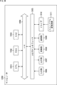
- FIG. 29 is a block diagram illustrating a schematic configuration example of a vehicle control system 7000 that is an example of a mobile control system to which the technology according to the present disclosure can be applied.
- the vehicle control system 7000 includes a plurality of electronic control units connected via a communication network 7010.
- the vehicle control system 7000 includes a drive system control unit 7100, a body system control unit 7200, a battery control unit 7300, a vehicle exterior information detection unit 7400, a vehicle interior information detection unit 7500, and an integrated control unit 7600. .
- the communication network 7010 for connecting the plurality of control units conforms to an arbitrary standard such as CAN (Controller Area Network), LIN (Local Interconnect Network), LAN (Local Area Network), or FlexRay (registered trademark). It may be an in-vehicle communication network.
- Each control unit includes a microcomputer that performs arithmetic processing according to various programs, a storage unit that stores programs executed by the microcomputer or parameters used for various calculations, and a drive circuit that drives various devices to be controlled. Is provided.
- Each control unit includes a network I / F for communicating with other control units via a communication network 7010, and is connected to devices or sensors inside and outside the vehicle by wired communication or wireless communication. A communication I / F for performing communication is provided. In FIG.
- control unit 7600 29, as a functional configuration of the integrated control unit 7600, a microcomputer 7610, a general-purpose communication I / F 7620, a dedicated communication I / F 7630, a positioning unit 7640, a beacon receiving unit 7650, an in-vehicle device I / F 7660, an audio image output unit 7670, An in-vehicle network I / F 7680 and a storage unit 7690 are illustrated.
- other control units include a microcomputer, a communication I / F, a storage unit, and the like.
- the drive system control unit 7100 controls the operation of the device related to the drive system of the vehicle according to various programs.
- the drive system control unit 7100 includes a driving force generator for generating a driving force of a vehicle such as an internal combustion engine or a driving motor, a driving force transmission mechanism for transmitting the driving force to wheels, and a steering angle of the vehicle. It functions as a control device such as a steering mechanism that adjusts and a braking device that generates a braking force of the vehicle.
- the drive system control unit 7100 may have a function as a control device such as ABS (Antilock Brake System) or ESC (Electronic Stability Control).
- a vehicle state detection unit 7110 is connected to the drive system control unit 7100.
- the vehicle state detection unit 7110 includes, for example, a gyro sensor that detects the angular velocity of the rotational movement of the vehicle body, an acceleration sensor that detects the acceleration of the vehicle, an operation amount of an accelerator pedal, an operation amount of a brake pedal, and steering of a steering wheel. At least one of sensors for detecting an angle, an engine speed, a rotational speed of a wheel, or the like is included.
- the drive system control unit 7100 performs arithmetic processing using a signal input from the vehicle state detection unit 7110, and controls an internal combustion engine, a drive motor, an electric power steering device, a brake device, or the like.
- the body system control unit 7200 controls the operation of various devices mounted on the vehicle body according to various programs.
- the body system control unit 7200 functions as a keyless entry system, a smart key system, a power window device, or a control device for various lamps such as a headlamp, a back lamp, a brake lamp, a blinker, or a fog lamp.
- the body control unit 7200 can be input with radio waves or various switch signals transmitted from a portable device that substitutes for a key.
- the body system control unit 7200 receives input of these radio waves or signals, and controls a door lock device, a power window device, a lamp, and the like of the vehicle.
- the battery control unit 7300 controls the secondary battery 7310 that is a power supply source of the drive motor according to various programs. For example, information such as battery temperature, battery output voltage, or remaining battery capacity is input to the battery control unit 7300 from a battery device including the secondary battery 7310. The battery control unit 7300 performs arithmetic processing using these signals, and controls the temperature adjustment of the secondary battery 7310 or the cooling device provided in the battery device.
- the outside information detection unit 7400 detects information outside the vehicle on which the vehicle control system 7000 is mounted.
- the outside information detection unit 7400 is connected to at least one of the imaging unit 7410 and the outside information detection unit 7420.
- the imaging unit 7410 includes at least one of a ToF (Time Of Flight) camera, a stereo camera, a monocular camera, an infrared camera, and other cameras.
- the outside information detection unit 7420 detects, for example, current weather or an environmental sensor for detecting weather, or other vehicles, obstacles, pedestrians, etc. around the vehicle equipped with the vehicle control system 7000. At least one of the surrounding information detection sensors.
- the environmental sensor may be, for example, at least one of a raindrop sensor that detects rainy weather, a fog sensor that detects fog, a sunshine sensor that detects sunlight intensity, and a snow sensor that detects snowfall.
- the ambient information detection sensor may be at least one of an ultrasonic sensor, a radar device, and a LIDAR (Light Detection and Ranging, Laser Imaging Detection and Ranging) device.
- the imaging unit 7410 and the outside information detection unit 7420 may be provided as independent sensors or devices, or may be provided as a device in which a plurality of sensors or devices are integrated.
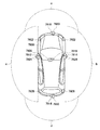
- FIG. 30 shows an example of installation positions of the imaging unit 7410 and the vehicle outside information detection unit 7420.
- the imaging units 7910, 7912, 7914, 7916, and 7918 are provided at, for example, at least one of the front nose, the side mirror, the rear bumper, the back door, and the upper part of the windshield in the vehicle interior of the vehicle 7900.
- An imaging unit 7910 provided in the front nose and an imaging unit 7918 provided in the upper part of the windshield in the vehicle interior mainly acquire an image in front of the vehicle 7900.
- Imaging units 7912 and 7914 provided in the side mirror mainly acquire an image of the side of the vehicle 7900.
- An imaging unit 7916 provided in the rear bumper or the back door mainly acquires an image behind the vehicle 7900.
- the imaging unit 7918 provided on the upper part of the windshield in the passenger compartment is mainly used for detecting a preceding vehicle or a pedestrian, an obstacle, a traffic light, a traffic sign, a lane, or
- FIG. 30 shows an example of shooting ranges of the respective imaging units 7910, 7912, 7914, and 7916.
- the imaging range a indicates the imaging range of the imaging unit 7910 provided in the front nose
- the imaging ranges b and c indicate the imaging ranges of the imaging units 7912 and 7914 provided in the side mirrors, respectively
- the imaging range d The imaging range of the imaging part 7916 provided in the rear bumper or the back door is shown. For example, by superimposing the image data captured by the imaging units 7910, 7912, 7914, and 7916, an overhead image when the vehicle 7900 is viewed from above is obtained.
- the vehicle outside information detection units 7920, 7922, 7924, 7926, 7928, and 7930 provided on the front, rear, sides, corners of the vehicle 7900 and the upper part of the windshield in the vehicle interior may be, for example, an ultrasonic sensor or a radar device.
- the vehicle outside information detection units 7920, 7926, and 7930 provided on the front nose, the rear bumper, the back door, and the windshield in the vehicle interior of the vehicle 7900 may be, for example, LIDAR devices.
- These outside information detection units 7920 to 7930 are mainly used for detecting a preceding vehicle, a pedestrian, an obstacle, and the like.
- the vehicle exterior information detection unit 7400 causes the imaging unit 7410 to capture an image outside the vehicle and receives the captured image data. Further, the vehicle exterior information detection unit 7400 receives detection information from the vehicle exterior information detection unit 7420 connected thereto. When the vehicle exterior information detection unit 7420 is an ultrasonic sensor, a radar device, or a LIDAR device, the vehicle exterior information detection unit 7400 transmits ultrasonic waves, electromagnetic waves, or the like, and receives received reflected wave information.
- the outside information detection unit 7400 may perform an object detection process or a distance detection process such as a person, a car, an obstacle, a sign, or a character on a road surface based on the received information.
- the vehicle exterior information detection unit 7400 may perform environment recognition processing for recognizing rainfall, fog, road surface conditions, or the like based on the received information.
- the vehicle outside information detection unit 7400 may calculate a distance to an object outside the vehicle based on the received information.
- the outside information detection unit 7400 may perform image recognition processing or distance detection processing for recognizing a person, a car, an obstacle, a sign, a character on a road surface, or the like based on the received image data.
- the vehicle exterior information detection unit 7400 performs processing such as distortion correction or alignment on the received image data, and combines the image data captured by the different imaging units 7410 to generate an overhead image or a panoramic image. Also good.
- the vehicle exterior information detection unit 7400 may perform viewpoint conversion processing using image data captured by different imaging units 7410.
- the vehicle interior information detection unit 7500 detects vehicle interior information.
- a driver state detection unit 7510 that detects the driver's state is connected to the in-vehicle information detection unit 7500.
- Driver state detection unit 7510 may include a camera that captures an image of the driver, a biosensor that detects biometric information of the driver, a microphone that collects sound in the passenger compartment, and the like.
- the biometric sensor is provided, for example, on a seat surface or a steering wheel, and detects biometric information of an occupant sitting on the seat or a driver holding the steering wheel.
- the vehicle interior information detection unit 7500 may calculate the degree of fatigue or concentration of the driver based on the detection information input from the driver state detection unit 7510, and determines whether the driver is asleep. May be.
- the vehicle interior information detection unit 7500 may perform a process such as a noise canceling process on the collected audio signal.
- the integrated control unit 7600 controls the overall operation in the vehicle control system 7000 according to various programs.
- An input unit 7800 is connected to the integrated control unit 7600.
- the input unit 7800 is realized by a device that can be input by a passenger, such as a touch panel, a button, a microphone, a switch, or a lever.
- the integrated control unit 7600 may be input with data obtained by recognizing voice input through a microphone.
- the input unit 7800 may be, for example, a remote control device using infrared rays or other radio waves, or may be an external connection device such as a mobile phone or a PDA (Personal Digital Assistant) that supports the operation of the vehicle control system 7000. May be.
- the input unit 7800 may be, for example, a camera.
- the passenger can input information using a gesture.
- data obtained by detecting the movement of the wearable device worn by the passenger may be input.
- the input unit 7800 may include, for example, an input control circuit that generates an input signal based on information input by a passenger or the like using the input unit 7800 and outputs the input signal to the integrated control unit 7600.
- a passenger or the like operates the input unit 7800 to input various data or instruct a processing operation to the vehicle control system 7000.
- the storage unit 7690 may include a ROM (Read Only Memory) that stores various programs executed by the microcomputer, and a RAM (Random Access Memory) that stores various parameters, calculation results, sensor values, and the like.
- the storage unit 7690 may be realized by a magnetic storage device such as an HDD (Hard Disc Drive), a semiconductor storage device, an optical storage device, a magneto-optical storage device, or the like.
- General-purpose communication I / F 7620 is a general-purpose communication I / F that mediates communication with various devices existing in the external environment 7750.
- General-purpose communication I / F7620 is a cellular communication protocol such as GSM (Global System of Mobile communications), WiMAX, LTE (Long Term Evolution) or LTE-A (LTE-Advanced), or wireless LAN (Wi-Fi (registered trademark)). Other wireless communication protocols such as Bluetooth (registered trademark) may also be implemented.
- the general-purpose communication I / F 7620 is connected to a device (for example, an application server or a control server) existing on an external network (for example, the Internet, a cloud network, or an operator-specific network) via, for example, a base station or an access point.
- the general-purpose communication I / F 7620 is a terminal (for example, a driver, a pedestrian or a store terminal, or an MTC (Machine Type Communication) terminal) that exists in the vicinity of the vehicle using, for example, P2P (Peer To Peer) technology. You may connect with.
- a terminal for example, a driver, a pedestrian or a store terminal, or an MTC (Machine Type Communication) terminal
- P2P Peer To Peer
- the dedicated communication I / F 7630 is a communication I / F that supports a communication protocol formulated for use in vehicles.
- the dedicated communication I / F 7630 is a standard protocol such as WAVE (Wireless Access in Vehicle Environment), DSRC (Dedicated Short Range Communications), or cellular communication protocol, which is a combination of the lower layer IEEE 802.11p and the upper layer IEEE 1609. May be implemented.
- the dedicated communication I / F 7630 typically includes vehicle-to-vehicle communication, vehicle-to-infrastructure communication, vehicle-to-home communication, and vehicle-to-pedestrian communication. ) Perform V2X communication, which is a concept that includes one or more of the communications.
- the positioning unit 7640 receives, for example, a GNSS signal from a GNSS (Global Navigation Satellite System) satellite (for example, a GPS signal from a GPS (Global Positioning System) satellite), performs positioning, and performs latitude, longitude, and altitude of the vehicle.
- the position information including is generated.
- the positioning unit 7640 may specify the current position by exchanging signals with the wireless access point, or may acquire position information from a terminal such as a mobile phone, PHS, or smartphone having a positioning function.
- the beacon receiving unit 7650 receives, for example, radio waves or electromagnetic waves transmitted from a radio station installed on the road, and acquires information such as the current position, traffic jam, closed road, or required time. Note that the function of the beacon receiving unit 7650 may be included in the dedicated communication I / F 7630 described above.
- the in-vehicle device I / F 7660 is a communication interface that mediates the connection between the microcomputer 7610 and various in-vehicle devices 7760 present in the vehicle.
- the in-vehicle device I / F 7660 may establish a wireless connection using a wireless communication protocol such as a wireless LAN, Bluetooth (registered trademark), NFC (Near Field Communication), or WUSB (Wireless USB).
- the in-vehicle device I / F 7660 is connected to a USB (Universal Serial Bus), HDMI (High-Definition Multimedia Interface), or MHL (Mobile High-definition Link) via a connection terminal (and a cable if necessary). ) Etc. may be established.
- the in-vehicle device 7760 may include, for example, at least one of a mobile device or a wearable device that a passenger has, or an information device that is carried into or attached to the vehicle.
- In-vehicle device 7760 may include a navigation device that searches for a route to an arbitrary destination.
- In-vehicle device I / F 7660 exchanges control signals or data signals with these in-vehicle devices 7760.
- the in-vehicle network I / F 7680 is an interface that mediates communication between the microcomputer 7610 and the communication network 7010.
- the in-vehicle network I / F 7680 transmits and receives signals and the like in accordance with a predetermined protocol supported by the communication network 7010.
- the microcomputer 7610 of the integrated control unit 7600 is connected via at least one of a general-purpose communication I / F 7620, a dedicated communication I / F 7630, a positioning unit 7640, a beacon receiving unit 7650, an in-vehicle device I / F 7660, and an in-vehicle network I / F 7680.
- the vehicle control system 7000 is controlled according to various programs based on the acquired information. For example, the microcomputer 7610 calculates a control target value of the driving force generation device, the steering mechanism, or the braking device based on the acquired information inside and outside the vehicle, and outputs a control command to the drive system control unit 7100. Also good.
- the microcomputer 7610 realizes ADAS (Advanced Driver Assistance System) functions including vehicle collision avoidance or impact mitigation, following traveling based on inter-vehicle distance, vehicle speed maintaining traveling, vehicle collision warning, or vehicle lane departure warning. You may perform the cooperative control for the purpose. Further, the microcomputer 7610 controls the driving force generator, the steering mechanism, the braking device, or the like based on the acquired information on the surroundings of the vehicle, so that the microcomputer 7610 automatically travels independently of the driver's operation. You may perform the cooperative control for the purpose of driving.
- ADAS Advanced Driver Assistance System
- the microcomputer 7610 is information acquired via at least one of the general-purpose communication I / F 7620, the dedicated communication I / F 7630, the positioning unit 7640, the beacon receiving unit 7650, the in-vehicle device I / F 7660, and the in-vehicle network I / F 7680.
- the three-dimensional distance information between the vehicle and the surrounding structure or an object such as a person may be generated based on the above and local map information including the peripheral information of the current position of the vehicle may be created.
- the microcomputer 7610 may generate a warning signal by predicting a danger such as a collision of a vehicle, approach of a pedestrian or the like or an approach to a closed road based on the acquired information.
- the warning signal may be, for example, a signal for generating a warning sound or lighting a warning lamp.
- the audio image output unit 7670 transmits an output signal of at least one of audio and image to an output device capable of visually or audibly notifying information to a vehicle occupant or the outside of the vehicle.
- an audio speaker 7710, a display unit 7720, and an instrument panel 7730 are illustrated as output devices.
- Display unit 7720 may include at least one of an on-board display and a head-up display, for example.
- the display portion 7720 may have an AR (Augmented Reality) display function.
- the output device may be other devices such as headphones, wearable devices such as glasses-type displays worn by passengers, projectors, and lamps.
- the display device can display the results obtained by various processes performed by the microcomputer 7610 or information received from other control units in various formats such as text, images, tables, and graphs. Display visually. Further, when the output device is an audio output device, the audio output device converts an audio signal made up of reproduced audio data or acoustic data into an analog signal and outputs it aurally.
- At least two control units connected via the communication network 7010 may be integrated as one control unit.
- each control unit may be configured by a plurality of control units.
- the vehicle control system 7000 may include another control unit not shown.
- some or all of the functions of any of the control units may be given to other control units. That is, as long as information is transmitted and received via the communication network 7010, the predetermined arithmetic processing may be performed by any one of the control units.
- a sensor or device connected to one of the control units may be connected to another control unit, and a plurality of control units may transmit / receive detection information to / from each other via the communication network 7010. .
- a computer program for realizing each function of the camera unit 10 according to the present embodiment described with reference to FIG. 7 can be implemented in any control unit or the like. It is also possible to provide a computer-readable recording medium in which such a computer program is stored.
- the recording medium is, for example, a magnetic disk, an optical disk, a magneto-optical disk, a flash memory, or the like. Further, the above computer program may be distributed via a network, for example, without using a recording medium.
- the camera unit 10 can be applied to the integrated control unit 7600 of the application example illustrated in FIG.
- the signal processing unit 104 and the timing control unit 106 of the camera unit 10 correspond to the microcomputer 7610 of the integrated control unit 7600.
- the integrated control unit 7600 combines a plurality of images taken with different exposure amounts, the maximum value of each image in consideration of the exposure ratio is blended according to the difference amount of pixel values of the same coordinates,
- exposure control is performed to make the exposure periods as close as possible to ensure that the subject to be flashed (flashes rapidly) in a scene with a very large luminance difference. Can be taken.
- the components of the camera unit 10 described with reference to FIG. 7 is realized in a module (for example, an integrated circuit module configured by one die) for the integrated control unit 7600 illustrated in FIG. May be. Or the camera unit 10 demonstrated using FIG. 7 may be implement
- this technique can take the following structures.
- a detection unit for detecting a difference between a plurality of images photographed at different exposure times;
- a synthesis coefficient calculation unit that calculates a synthesis coefficient indicating a synthesis ratio of the plurality of images based on the difference;
- a combining unit that combines the plurality of images based on the combining coefficient;
- a signal processing apparatus comprising: (2) A controller for controlling exposure times of the plurality of images;
- the plurality of images include a first image having a first exposure time and a second image having a second exposure time different from the first exposure time,
- the control unit controls to capture the second image following the first image, and minimizes the interval between the exposure end of the first image and the exposure start of the second image.
- the synthesized reference signal generation unit generates a first synthesized reference signal corresponding to the first image and a second synthesized reference signal corresponding to the second image;
- the detection unit detects a magnitude relationship between the first combined reference signal and the second combined reference signal as the difference,
- the synthesis coefficient calculation unit calculates a synthesis coefficient so as to increase a synthesis ratio of an image corresponding to a large synthesis reference signal among the first synthesis reference signal and the second synthesis reference signal.
- the signal processing apparatus according to the above.
- the plurality of images further includes a third image having a third exposure time different from both the first exposure time and the second exposure time
- the control unit controls to capture the third image following the second image, and minimizes the interval between the end of exposure of the second image and the start of exposure of the third image (2)
- the signal processing apparatus as described.
- the control unit controls the first exposure time to be longer than the second exposure time and the second exposure time to be longer than the third exposure time
- the signal processing apparatus according to (8), wherein the synthesizing unit synthesizes the third image with an intermediate synthesized image obtained by synthesizing the first image and the second image.
- the synthesis coefficient calculation unit includes: a first synthesis coefficient indicating a synthesis ratio of the first image and the second image; and a second synthesis coefficient indicating a synthesis ratio of the intermediate synthesized image and the third image. Calculate The synthesizing unit synthesizes the first image and the second image based on the first synthesis coefficient, and synthesizes the intermediate synthesized image and the third image based on the second synthesis coefficient.
- the signal processing device according to (9).
- (11) The signal processing apparatus according to (2), wherein the control unit controls the total exposure time of each of the plurality of images to be longer than a turn-off time of a blinking subject.
Landscapes
- Engineering & Computer Science (AREA)
- Multimedia (AREA)
- Signal Processing (AREA)
- Physics & Mathematics (AREA)
- General Physics & Mathematics (AREA)
- Computing Systems (AREA)
- Theoretical Computer Science (AREA)
- Studio Devices (AREA)
Abstract
本技術は、輝度差が非常に大きいシーンにおいて、点滅する撮影対象を確実に撮影することができるようにする信号処理装置、撮影装置、及び、信号処理方法に関する。 異なる露光時間で撮影された複数の画像間における差分を検出し、その差分に基づいて、複数の画像の合成割合を示す合成係数を算出し、その合成係数に基づいて複数の画像を合成することで、輝度差が非常に大きいシーンにおいて、点滅する撮影対象を確実に撮影することができる。本技術は、例えば、画像を撮影するカメラユニット等に適用することができる。
Description
本技術は、信号処理装置、撮影装置、及び、信号処理方法に関し、特に、例えば、輝度差が非常に大きいシーンにおいて、点滅する撮影対象を確実に撮影することができるようにした信号処理装置、撮影装置、及び、信号処理方法に関する。
近年、自動運転など高度な運転制御を実現する事を目的として自動車に車載カメラが搭載されるケースが増えている。
しかしながら、車載カメラでは安全性を確保するため、トンネルの出口など輝度差が非常に大きい条件においても視認性を担保する事が求められており、画像の白飛びを抑えて広ダイナミックレンジ化するための技術が必要な状況である。このような白飛びの対策としては、例えば、特許文献1に開示されている技術が知られている。
また、近年、信号機や、電子的な道路標識の光源が、白熱電球等からLED(Light Emitting Diode)に置き換わりつつある。
LEDは、白熱電球に比較して、明滅の応答速度が高速であるため、例えば、自動車等に搭載される車載カメラ等で、LEDの信号機や道路標識を撮影すると、フリッカが発生し、信号機や道路標識が消灯した状態で撮影される。このようなフリッカの対策としては、例えば、特許文献2に開示されている技術が知られている。
ところで、トンネルの出口など輝度差が非常に大きいシーンにおいて、明滅の応答速度が高速なLEDの信号機や道路標識などを確実に撮影するための技術は確立されておらず、そのような技術が求められていた。
本技術はこのような状況に鑑みてなされたものであり、輝度差が非常に大きいシーンにおいて、点滅する撮影対象を確実に撮影することができるようにするものである。
本技術の一側面の信号処理装置は、異なる露光時間で撮影された複数の画像間における差分を検出する検出部と、前記差分に基づいて、前記複数の画像の合成割合を示す合成係数を算出する合成係数算出部と、前記合成係数に基づいて前記複数の画像を合成する合成部と、を備える信号処理装置である。
本技術の一側面の撮影装置は、異なる露光時間で撮影された複数の画像を生成する画像生成部と、前記複数の画像間における差分を検出する検出部と、前記差分に基づいて、前記複数の画像の合成割合を示す合成係数を算出する合成係数算出部と、前記合成係数に基づいて前記複数の画像を合成する合成部と、を備える撮影装置である。
本技術の一側面の信号処理方法は、異なる露光時間で撮影された複数の画像間における差分を検出することと、前記差分に基づいて、前記複数の画像の合成割合を示す合成係数を算出することと、前記合成係数に基づいて前記複数の画像を合成することと、を含む信号処理方法である。
本技術の一側面の信号処理装置、撮影装置、及び信号処理方法においては、異なる露光時間で撮影された複数の画像間における差分が検出され、前記差分に基づいて、前記複数の画像の合成割合を示す合成係数が算出され、前記合成係数に基づいて前記複数の画像が合成される。
信号処理装置や撮影装置は、独立した装置であってもよいし、1つの装置を構成している内部ブロックであってもよい。
本技術の一側面によれば、輝度差が非常に大きいシーンにおいて、点滅する撮影対象を確実に撮影することができる。
なお、ここに記載された効果は必ずしも限定されるものではなく、本開示中に記載されたいずれかの効果であってもよい。
以下、図面を参照しながら本技術の実施の形態について説明する。なお、説明は以下の順序で行うものとする。
1.本技術の概要
2.本技術の実施の形態
3.本技術の実施の形態の変形例
4.本技術の信号処理の詳細な内容
5.固体撮像装置の構成例
6.コンピュータの構成例
7.応用例
2.本技術の実施の形態
3.本技術の実施の形態の変形例
4.本技術の信号処理の詳細な内容
5.固体撮像装置の構成例
6.コンピュータの構成例
7.応用例
<1.本技術の概要>
(輝度差が非常に大きい撮影対象の撮影の例)
近年、自動運転など高度な運転制御を実現する事を目的として自動車に車載カメラが搭載されるケースが増えている。しかしながら、車載カメラでは安全性を確保するため、トンネルの出口など輝度差が非常に大きい条件においても視認性を担保する事が求められており、画像の白飛びを抑えて広ダイナミックレンジ化するための技術が必要な状況である。
近年、自動運転など高度な運転制御を実現する事を目的として自動車に車載カメラが搭載されるケースが増えている。しかしながら、車載カメラでは安全性を確保するため、トンネルの出口など輝度差が非常に大きい条件においても視認性を担保する事が求められており、画像の白飛びを抑えて広ダイナミックレンジ化するための技術が必要な状況である。
図1は、輝度差が非常に大きい撮影対象の撮影の例を説明する図である。図1においては、トンネルの出口の撮影の例を示しているが、トンネルの出口の状況が認識できないと、安全を確保するための運転制御を行うことができない。
(点滅する撮影対象の撮影の例)
また、近年において、信号機や標識の光源が電球からLEDに置き換わりつつある。しかしながらLEDは明滅の応答速度が従来式の電球に比べて高速であるため、撮影装置でLEDの信号機や標識を撮影するとフリッカが発生し消灯して見えてしまうという問題があり、ドライブレコーダの証拠能力の担保や自動車の運転自動化に向けて大きな課題となっている。
また、近年において、信号機や標識の光源が電球からLEDに置き換わりつつある。しかしながらLEDは明滅の応答速度が従来式の電球に比べて高速であるため、撮影装置でLEDの信号機や標識を撮影するとフリッカが発生し消灯して見えてしまうという問題があり、ドライブレコーダの証拠能力の担保や自動車の運転自動化に向けて大きな課題となっている。
図2は、点滅する撮影対象の撮影の例を説明する図である。図2において、第1フレーム(Frame1)と第2フレーム(Frame2)の画像では、青(左端)が点灯している信号機が映っているが、第3フレーム(Frame3)と第4フレーム(Frame4)の画像では、消灯している状態の信号機が映っている。
このように、信号機が消灯した状態で映ることは、例えば、ドライブレコーダに利用されている場合に、映像(画像)の証拠能力に支障をきたす原因になる。また、信号機が消灯した状態で映ることは、その画像が、例えば、自動車の自動運転に利用されている場合に、自動車の停止等の運転制御に支障をきたす原因になる。
(輝度差が非常に大きいシーンにおいて、点滅する撮影対象に対する対処方法)
ここで、上述した特許文献1には、複数の異なる露光量で撮影された画像を合成する事で白飛びを抑制し、見かけのダイナミックレンジを拡大する手法が提案されている。この手法においては、図3に示すように、露光時間の長い長時間露光画像(長蓄画像)の輝度値を参照し、明るさが所定の閾値を下回れば長時間露光画像(長蓄画像)、上回れば短時間露光画像(短蓄画像)を出力する事で、広いダイナミックレンジを持つ画像を生成する事が可能となる。
ここで、上述した特許文献1には、複数の異なる露光量で撮影された画像を合成する事で白飛びを抑制し、見かけのダイナミックレンジを拡大する手法が提案されている。この手法においては、図3に示すように、露光時間の長い長時間露光画像(長蓄画像)の輝度値を参照し、明るさが所定の閾値を下回れば長時間露光画像(長蓄画像)、上回れば短時間露光画像(短蓄画像)を出力する事で、広いダイナミックレンジを持つ画像を生成する事が可能となる。
一方で、図2に示したように、LED信号機など高輝度な被写体が点滅をしている場合に、長時間露光画像(長蓄画像)と短時間露光画像(短蓄画像)の合成を行う事で、本来信号機の点灯状態が記録されるべきであるにも関わらず消灯状態が記録されてしまう場合がある。図4には、信号機の点灯状態が記録されるべきであるにも関わらず、消灯状態が記録されてしまう場合の例を示している。
図4の例においては、長蓄画像にのみ、LED点灯状態が映っている場合に、光源が明るいため、信号が飽和して閾値を上回っている。そのため、長蓄画像から短蓄画像への置き換えが生じることになるが、短蓄画像には、LED点灯状態が映っていないため、消灯状態が発生してしまう。また、図4の例においては、短蓄画像にのみ、LED点灯状態が映っている場合に、長蓄画像の明るさが、閾値を下回っているため、長蓄画像から短蓄画像への置き換えは発生しない。その結果、長蓄画像にはLEDの点灯状態が映っていないため、消灯状態が発生してしまう。
また、図2に示したLEDのフリッカに対しては、点滅光源の消灯期間を上回る露光時間で撮影を行う事で、発光期間の撮り逃しを防ぐ手法がある。例えば、光源の点滅周波数が100Hz、発光Duty比が60%であれば消灯期間4msを露光時間の下限値とし、常にそれ以上の露光時間を確保する事で光源の点灯状態を撮影し続ける事ができる(上述した特許文献2参照)。図5には、点滅光源の消灯期間を上回る露光時間で撮影を行う場合の例を示している。図5の例では、消灯期間4msの場合において、4ms < 露光時間となっている。
しかしながら、車載カメラなどレンズF値を固定で使用しなければならないシステムの場合、晴天時の屋外など照度の高い状況下では、露光時間を光源の消灯期間よりも短くできないため、露光過多となり、被写体の視認性が低下してしまう。そのため、図1に示した画像の白飛びが発生するような輝度差の大きいシーンにおいては、画像のダイナミックレンジを拡大する効果は得られない。
さらに、図2に示したLEDのフリッカに対しては、撮像素子において光源の点滅周期をN等分割したタイミングでN回撮影を行い、N枚の撮影データを取得した後、それらの画像の平均値ないし最大値を選択する手法がある。
この手法を用いることで、例えば100Hzで点滅している光源の点滅周期10msを3等分割したタイミングで3回撮影を行い、3枚の撮影データの平均値ないし最大値を選択する事で、LEDの消灯状態が記録されてしまう事を抑制する事が可能となる。
図6には、光源の点滅周期をN等分割したタイミングでN回撮影を行い、N枚の撮影データを取得する場合の例を示している。図6においては、点滅周期(Tb)の光源に対して、点滅周期を3等分したタイミングで3回撮影を行う場合を例示している。また、図6においては、S0,S1,S2は、1フレーム以内で3回撮影を行う際のそれぞれの露光タイミングを示している。それぞれの露光における露光時間(Tc)は同一である。
S0の露光開始時間を、0とすると、S0,S1,S2のそれぞれの露光タイミングは、以下の通りとなる。
S0の露光開始時間:0,S0の露光終了時間:0 + Tc
S1の露光開始時間:Tb/3,S1の露光終了時間:Tb/3 + Tc
S2の露光開始時間:(Tb/3) × 2,S2の露光終了時間:(Tb/3) × 2 + Tc
S1の露光開始時間:Tb/3,S1の露光終了時間:Tb/3 + Tc
S2の露光開始時間:(Tb/3) × 2,S2の露光終了時間:(Tb/3) × 2 + Tc
しかしながら、図6に示した手法は、複数回の撮影を行う際に、それぞれの露光時間を同一にする事を前提とした技術であるため、図2に示したLEDのフリッカに対しては効果があるものの、図1に示した画像の白飛びが発生するような輝度差の大きいシーンにおいて、画像のダイナミックレンジを拡大する効果を得るまでは至らない。
以上のように、現状の技術では、図1に示した画像の白飛びが発生するような輝度差の大きいシーンにおいて、画像のダイナミックレンジを拡大することと、図2に示したLEDのフリッカの対策とを両立が可能な技術は、まだ確立されていない。本技術では、これらを両立させるために、以下の3つの技術的特徴を有する点をポイントとしている。
(1)映像信号のダイナミックレンジを拡大するため、撮像素子において複数の異なる露光量で撮影を行う際に、それらの露光期間を可能な限り近接させる露光制御を行う事で実効的な露光時間を伸ばし、高速点滅被写体の点灯期間を捕捉しやすくする。
(2)信号処理部において異なる露光量で撮影した複数の画像を合成する際に、露光比を加味したそれぞれの画像の最大値を同一座標の画素値の差分量に応じてブレンドする。その際に、ノイズ量を加味して動き判定を行う。
(3)上記の露光制御と信号処理の組み合わせによって、輝度差の大きなシーンにおいても白飛び、黒潰れを抑制すると同時に、LED信号機等の高速点滅被写体の点灯状態を正しく出力する事が可能な撮影装置を提供する。
(2)信号処理部において異なる露光量で撮影した複数の画像を合成する際に、露光比を加味したそれぞれの画像の最大値を同一座標の画素値の差分量に応じてブレンドする。その際に、ノイズ量を加味して動き判定を行う。
(3)上記の露光制御と信号処理の組み合わせによって、輝度差の大きなシーンにおいても白飛び、黒潰れを抑制すると同時に、LED信号機等の高速点滅被写体の点灯状態を正しく出力する事が可能な撮影装置を提供する。
本技術では、このような技術的特徴を有することで、輝度差が非常に大きいシーンにおいて、点滅(高速に点滅)する撮影対象を確実に撮影することが可能となり、その結果として、図1に示した画像の白飛びが発生するような輝度差の大きいシーンにおいて、画像のダイナミックレンジを拡大することと、図2に示したLEDのフリッカの対策とを両立することができる。
以下、このような本技術の技術的特徴を、具体的な実施の形態を参照しながら説明する。
<2.本技術の実施の形態>
(カメラユニットの構成例)
図7は、本技術を適用した撮影装置としてのカメラユニットの一実施の形態の構成例を示すブロック図である。
図7は、本技術を適用した撮影装置としてのカメラユニットの一実施の形態の構成例を示すブロック図である。
図7において、カメラユニット10は、レンズ101、撮像素子102、ディレイライン103、信号処理部104、出力部105、及びタイミング制御部106から構成される。
レンズ101は、被写体からの光を集光し、撮像素子102に入射させて結像させる。
撮像素子102は、例えば、CMOS(Complementary Metal Oxide Semiconductor)イメージセンサである。撮像素子102は、レンズ101からの入射光を受光し、光電変換を行うことにより、入射光に対応する撮影画像(の画像データ)を撮影する。
すなわち、撮像素子102は、タイミング制御部106から指定される撮影タイミングで撮影を行う撮影部として機能し、出力部105が出力する出力画像のフレームレートの期間に、N回の撮影を行い、そのN回の撮影により得られるN枚の撮影画像を、順次出力する。
ディレイライン103は、撮像素子102が順次出力するN枚の撮影画像を順次記憶し、そのN枚の撮影画像を、同時に、信号処理部104に供給する。
信号処理部104は、ディレイライン103からのN枚の撮影画像を処理し、1フレーム(枚)の出力画像を生成する。その際、信号処理部104は、撮影画像の画素値の差分量に応じてN枚の撮影画像の画像データの最大値をブレンドして、出力画像を生成する。
さらに、信号処理部104は、出力画像に対して、例えば、ノイズの除去や、WB(ホワイトバランス)の調整等の処理を行い、出力部105に供給する。また、信号処理部104は、ディレイライン103からのN枚の撮影画像の明るさから露光レベルを検出(検波)し、タイミング制御部106に供給する。
出力部105は、信号処理部104からの出力画像(映像データ)を出力する。
タイミング制御部106は、撮像素子102の撮影タイミングを制御する。すなわち、タイミング制御部106は、信号処理部104で検出された露光レベルに基づいて、撮像素子102の露光時間の調整を行う。その際に、タイミング制御部106は、N枚の撮影画像の露光タイミングを可能な限り近接させるようにシャッタ制御を行う。
カメラユニット10は、以上のように構成される。
(タイミング制御部のシャッタ制御の例)
次に、図8及び図9を参照して、図7のタイミング制御部106によるシャッタ制御について説明する。
次に、図8及び図9を参照して、図7のタイミング制御部106によるシャッタ制御について説明する。
図7のカメラユニット10において、撮像素子102は、露光時間の異なるN枚の撮影画像の撮影データを取得する。その際、タイミング制御部106は、それらの撮影期間を可能な限り近接させる事で実効的な露光時間を伸ばし、LED等の高速点滅被写体の点滅周期をカバーしやすくするための制御を行う。
ここでは、図8を参照しながら、その具体例として3枚の撮影画像を取得する際の露光タイミングについて説明する。図8において、T0,T1,T2は、1フレーム以内で3回撮影を行う際のそれぞれの露光タイミングを示している。それぞれの露光における露光時間の比率は、信号のダイナミックレンジを確保するために、例えば、T0:T1:T2 = 4:2:1の比率とすることができる。
この際、タイミング制御部106は、T0の露光が完了次第、すぐにT1の露光を開始し、T1の露光が完了次第、すぐにT2の露光を開始するように露光タイミングの制御を行う。すなわち、T0の露光終了とT1の露光開始との間隔、及びT1の露光終了とT2の露光開始との間隔が極小化されている。このような露光タイミング制御を行う事で、高速点滅被写体の点灯期間がT0,T1,T2のいずれかの露光期間とオーバーラップしやすくなり、点灯期間の画像を捕捉できる確率を上げることができる。
また、N枚の撮影画像の撮影期間を近接させることで、次のような効果が得られる。すなわち、図9のAと図9のBを比較して説明すれば、図9のAに示すように、T0,T1,T2の露光タイミングを離して設定する場合には、点灯期間が短い(発光Duty比が小さい)点滅光源の場合に、露光タイミングと発光タイミングがオーバーラップしない可能性がある。
一方で、図9のBに示すように、T0,T1,T2の露光タイミングを近接させる場合には、実効的な露光時間が伸びるため、点灯期間が短い点滅光源に対して露光タイミングと発光タイミングがオーバーラップする可能性を向上させることができる。なお、例えば、LED信号機の消灯期間は、典型的には3ms前後が想定されるので、タイミング制御部106は、この消灯期間に応じて、T0,T1,T2の露光タイミングを近接させる制御を行うことができる。
さらに、後述の信号処理部104にて、T0,T1,T2の最大値を出力する制御を行う場合に、T0,T1,T2の画素値が異なるような動体を撮影する場合は、二重エッジ像などのアーチファクトを発生させてしまうケースがあるが、T0,T1,T2の露光タイミングを近接させる事で、動体の見た目の動き量を小さく抑える事ができ、最大値出しの弊害を抑える効果も期待できる。
なお、T0,T1,T2の露光タイミングを近接させるシャッタ制御は、例えばフレーム間の読み出し動作とシャッタ動作とを時間的にオーバーラップさせるタイプのセンサを用いる事で実現できる。また、関連する技術としては、下記の特許文献3が開示されている。
特許文献3:特開2008-22485号公報
しかしながら、N枚の撮影期間を近接させて露光するだけでは、図2に示したLEDのフリッカの対策としては不十分である。すなわち、特許文献3に開示されている技術であると、例えば、第1サブフレームの信号のみにLEDの点灯状態が記録され、かつ画素値が飽和している場合に、信号のダイナミックレンジを拡大するために第2サブフレームの信号に値を置き換える合成処理を行ったとき、LEDの消灯が発生してしまうことになる。そこで、以下、このようなLEDの消灯が生じないようにするための信号処理部104の構成について説明する。
(信号処理部の構成例)
図10は、図7の信号処理部104の構成例を示す図である。
図10は、図7の信号処理部104の構成例を示す図である。
図10の信号処理部104においては、撮像素子102で取得されたN枚の撮影画像の画像データを処理し、1フレーム(枚)の出力画像に合成している。その際に、信号処理部104は、常にN枚の撮影画像の画像データ間で合成を行い、トータルN-1回の合成処理が行われるようにする。
図10においては、その最も単純な例として、2枚の撮影画像を、1枚の出力画像に合成する際の信号処理について説明する。
なお、図10においては、T0,T1は、1フレーム以内で2回撮影を行った際のそれぞれの露光時間に対応する撮影画像を示している。また、図10において、それぞれの露光における露光時間の比率は、信号のダイナミックレンジを確保するために、例えば、T0:T1 = 16:1の比率であると仮定する。T1の明るさをT0に合わせるための露光比ゲインを、SGAIN1と定義すると、SGAIN1 = T0の露光時間 / T1の露光時間 = 16[倍]となる。以下、このT0,T1に対応する撮影画像をそれぞれ、画像信号T0,画像信号T1とも記述する。
図10において、信号処理部104は、合成基準信号生成部121、合成係数算出部122、動き検出部123、合成係数変調部124、及び合成部125から構成される。
合成基準信号生成部121は、画像信号T0と画像信号T1を合成するための基準となる信号(基準信号S0,基準信号S1)を生成する。その際、合成基準信号生成部121は、画像信号T0から基準信号S0を、画像信号T1から基準信号S1を生成する。なお、基準となる基準信号S0,S1の生成方法としては、例えば、あらかじめ定められたタップ数でフィルタをかけて簡易的な輝度値を算出することで生成することができる。
合成基準信号生成部121は、画像信号T0と画像信号T1を、合成部125に供給する。また、合成基準信号生成部121は、基準信号S0を、合成係数算出部122及び動き検出部123に供給し、基準信号S1を、動き検出部123に供給する。
合成係数算出部122は、合成基準信号生成部121からの基準信号S0を参照して、画像信号T0と画像信号T1を合成するための合成係数を算出する。合成係数算出部122は、合成係数を、合成係数変調部124に供給する。
動き検出部123は、合成基準信号生成部121からの基準信号S0と、基準信号S1に露光比SGAIN1を信号の間の差分を動き量と定義して、動き判定を行う。その際、動き検出部123は、信号のノイズとLED等の高速点滅体の点滅を区別するために、動き量をセンサ特性から想定されるノイズ量と比較して動き係数を算出する。
ただし、その際、動き検出部123においては、例えば、S0<S1の場合と、S1<S0の場合で、動き判定の判定基準を分けるものとする。なお、動き検出部123での動き判定の詳細については、図18及び図19を参照して後述する。動き検出部123は、動き係数を、合成係数変調部124に供給する。
合成係数変調部124は、合成係数算出部122からの合成係数に対して、動き検出部123からの動き係数を加味した変調を行い、動き補償後合成係数を算出する。その際、合成係数変調部124は、動き量が大きい場合には、画像信号T0と、画像信号T1に露光比SGAIN1を乗じた信号のうち、どちらか大きい方が多く合成されるようにする。合成係数変調部124は、動き補償後合成係数を、合成部125に供給する。
合成部125は、合成基準信号生成部121からの画像信号T0と画像信号T1を、合成係数変調部124からの動き補償後合成係数で合成(アルファブレンド)して、その結果得られるHDR(High Dynamic Range)合成後信号としての合成後画像信号を出力する。
信号処理部104は、以上のように構成される。
(2枚合成を行う場合の信号処理)
次に、図11のフローチャートを参照して、図10の信号処理部104により実行される、2枚合成を行う場合の信号処理の流れを説明する。
次に、図11のフローチャートを参照して、図10の信号処理部104により実行される、2枚合成を行う場合の信号処理の流れを説明する。
ステップS11において、合成基準信号生成部121は、そこに入力される画像信号T0から、基準信号S0を生成する。
ステップS12において、合成基準信号生成部121は、そこに入力される画像信号T1から、基準信号S1を生成する。
なお、T0とT1の露光時間の比率は、例えば、T0:T1 = 16:1の比率とすることができる。したがって、画像信号T0は、長時間露光画像(長蓄画像)である一方で、画像信号T1は、短時間露光画像(短蓄画像)であるとも言える。
ステップS13において、合成係数算出部122は、ステップS11の処理で得られる基準信号S0から、合成係数を算出する。
ステップS14において、動き検出部123は、S0 < S1×S1露光比の関係を満たすかどうかを判定する。
ステップS14において、S0 < S1×S1露光比の関係を満たしていると判定された場合、処理は、ステップS15に進められる。ステップS15において、動き検出部123は、ノイズ正規化ゲイン1を用いて動き判定を行う。
一方で、ステップS14において、S0 < S1×S1露光比の関係を満たしていない、すなわち、S0 ≧ S1×S1露光比の関係になると判定された場合、処理は、ステップS16に進められる。ステップS16において、動き検出部123は、ノイズ正規化ゲイン0を用いて動き判定を行う。
ステップS15又はS16の処理で、動き判定が行われると、処理は、ステップS17に進められる。ステップS17において、動き検出部123は、ステップS15又はS16の処理で得られる動き判定の結果に基づいて、動きがあるかどうかを判定する。
ステップS17において、動きがあると判定された場合、処理は、ステップS18に進められる。ステップS18において、動き検出部123は、ステップS15又はS16の処理等で得られる動き量に応じて、動き係数を算出する。
なお、動き検出部123により実行されるステップS14乃至S18の処理の詳細は、図19を参照して後述するが、動き評価値の符号と露光比に応じたノイズ正規化ゲイン(0,1)を乗算した後に、動き判定処理を行うことで、動き検出の精度を向上させることができる。
ステップS19において、合成係数変調部124は、ステップS13の処理で得られる合成係数に対し、ステップS18の処理で得られる動き係数を用いて変調を行い、動き補償後合成係数を生成する。
一方で、ステップS17において、動きがないと判定された場合、処理は、ステップS20に進められる。ステップS20において、合成係数変調部124は、ステップS13の処理で得られる合成係数をそのまま、動き補償後合成係数として使用するようにする。
ステップS19又はS20の処理で、動き補償後合成係数が得られると、処理は、ステップS21に進められる。
ステップS21において、合成部125は、ステップS19又はS20の処理で得られる動き補償後合成係数を参照して、画像信号T0と画像信号T1とを合成する。すなわち、合成部125では、動き補償後合成係数を用いることで、動き量が大きい場合に、画像信号T0と、画像信号T1に露光比SGAIN1(= 16)を乗じた信号のうち、どちらか大きい方が多く合成されることになる。
ステップS22において、合成部125は、ステップS21の処理で得られる合成後画像信号を出力する。
以上、2枚合成を行う場合の信号処理の流れを説明した。
(信号処理部の処理結果の例)
次に、図12及び図13を参照して、図7の信号処理部104による信号処理(図11)の処理結果について説明する。
次に、図12及び図13を参照して、図7の信号処理部104による信号処理(図11)の処理結果について説明する。
図12には、LED信号機が映っている撮影画像に対する信号処理の処理結果を示している。なお、ここでは、図12のAに、従来の手法を用いた場合の処理結果を示して、図12のBの本技術の手法を用いた場合の処理結果と比較している。
図12のAの従来の手法の場合、長蓄画像(画像信号T0)にのみLED信号機の点灯状態が記録されており、かつ長蓄(T0)の画素値が飽和している状況で、信号のダイナミックレンジを拡大するために、長蓄(T0)の飽和レベルを超えた画素値を短蓄(T1)に置き換えると、短蓄画像(画像信号T1)では、LED信号機が消灯しているため、置き換え後の信号も消灯が発生することになる。
一方で、図12のBの本技術の手法の場合、信号のダイナミックレンジを拡大するために、長蓄(T0)の飽和レベルを超えた画素値を短蓄(T1)に置き換える際に、長蓄と短蓄×露光比(S0とS1×S1露光比)の信号に大きな差分がある場合には、高速点滅体の点滅が発生していると判断して、どちらか大きい値を出力することになる。そのため、LED信号機の点灯状態が記録されている長蓄画像(画像信号T0)が選択され、図12のBの本技術の手法の場合には、LED信号機の消灯が発生しないことになる。
図13には、LED速度規制標識が映っている撮影画像に対する信号処理の処理結果を示している。なお、ここでは、図13のAに、従来の手法を用いた場合の処理結果を示して、図13のBの本技術の手法を用いた場合の処理結果と比較している。
図13のAの従来の手法の場合、長蓄画像(画像信号T0)にのみLED速度規制標識の点灯状態が記録されており、かつ長蓄(T0)の画素値が飽和している状況で、信号のダイナミックレンジを拡大するために、長蓄(T0)の飽和レベルを超えた画素値を短蓄(T1)に置き換えると、短蓄画像(画像信号T1)では、LED速度規制標識が消灯しているため、置き換え後の信号も消灯が発生することになる。
一方で、図13のBの本技術の手法の場合、信号のダイナミックレンジを拡大するために、長蓄(T0)の飽和レベルを超えた画素値を短蓄(T1)に置き換える際に、長蓄と短蓄×露光比(S0とS1×S1露光比)の信号に大きな差分がある場合には、高速点滅体の点滅が発生していると判断して、どちらか大きい値を出力することになる。そのため、LED速度規制標識の点灯状態が記録されている長蓄(S0とS1×S1露光比)が選択され、図13のBの本技術の手法の場合には、LED速度規制標識の消灯が発生しないことになる。
<3.本技術の実施の形態の変形例>
(3枚合成を行う場合の信号処理部の構成例)
図14は、3枚合成を行う場合の信号処理部104の構成例を示す図である。
図14は、3枚合成を行う場合の信号処理部104の構成例を示す図である。
すなわち、上述した説明では、最も単純な例として、2枚の撮影画像を、1枚の出力画像に合成する際の信号処理について説明したが、図14においては、3枚の撮影画像を、1枚の出力画像に合成する際の信号処理について説明する。
なお、図14においては、T0,T1,T2は、1フレーム以内で3回撮影を行った際のそれぞれの露光時間に対応する撮影画像を示している。また、図14において、それぞれの露光における露光時間の比率は、信号のダイナミックレンジを確保するために、例えば、T0:T1:T2 = 4:2:1の比率であると仮定する。T1の明るさをT0に合わせるための露光比ゲインをSGAIN1、T2の明るさをT0に合わせるための露光比ゲインをSGAIN2と定義する。上記の例では、SGAIN1 = 2,SGAIN2 = 4となる。以下、このT0,T1,T2に対応する撮影画像をそれぞれ、画像信号T0,画像信号T1,画像信号T2とも記述する。
図14において、信号処理部104は、合成基準信号生成部141、第1動き検出・合成係数算出部142、第1合成部143、第2動き検出・合成係数算出部144、及び第2合成部145から構成される。
合成基準信号生成部141は、画像信号T0,画像信号T1,画像信号T2を合成するための基準となる信号(基準信号S0,基準信号S1,基準信号S2)を生成する。その際、合成基準信号生成部141は、画像信号T0から基準信号S0を、画像信号T1から基準信号S1を、画像信号T2から基準信号S2をそれぞれ生成する。なお、基準となる基準信号S0,S1,S2の生成方法としては、例えば、あらかじめ定められたタップ数でフィルタをかけて簡易的な輝度値を算出することで生成することができる。
合成基準信号生成部141は、画像信号T0と画像信号T1を、第1合成部143に供給し、画像信号T2を、第2合成部145に供給する。また、合成基準信号生成部141は、基準信号S0と基準信号S1を、第1動き検出・合成係数算出部142に供給し、基準信号S1と基準信号S2を、第2動き検出・合成係数算出部144に供給する。
第1動き検出・合成係数算出部142は、合成基準信号生成部141からの基準信号S0を参照して、画像信号T0と画像信号T1を合成するための第1合成係数を算出する。また、第1動き検出・合成係数算出部142は、合成基準信号生成部141からの基準信号S0と、S1に露光比SGAIN1を乗じた信号の間の差分を第1動き量と定義して動き判定を行う。
その際、第1動き検出・合成係数算出部142は、信号のノイズとLED等の高速点滅体の点滅を区別するために、第1動き量をセンサ特性から想定されるノイズ量と比較して第1動き係数を算出する。ただし、動き判定を行う際には、例えば、S0 < S1となる場合と、S1 < S0となる場合で、動き判定の判定基準を分けるものとする。なお、第1動き検出・合成係数算出部142での動き判定の詳細については、図18及び図19を参照して後述する。
第1動き検出・合成係数算出部142は、第1合成係数に対して第1動き係数を加味した変調を行い、第1動き補償後合成係数を算出する。その際、第1動き検出・合成係数算出部142は、動き量が大きい場合には、画像信号T0と、画像信号T1に露光比SGAIN1を乗じた信号のうち、どちらか大きい方が多く合成されるようにする。第1動き検出・合成係数算出部142は、第1動き補償後合成係数を、第1合成部143に供給する。
また、第1動き検出・合成係数算出部142は、第1動き補償後合成係数を参照して、基準信号S0と基準信号S1とを合成(アルファブレンド)して、その結果得られるS0-S1合成信号を、第2動き検出・合成係数算出部144に供給する。
第1合成部143は、合成基準信号生成部141からの画像信号T0と画像信号T1を、第1動き検出・合成係数算出部142からの第1動き補償後合成係数で合成(アルファブレンド)して、その結果得られるT0-T1合成信号を、第2合成部145に供給する。
第2動き検出・合成係数算出部144は、合成基準信号生成部141からの基準信号S1を参照して、T0-T1合成信号と画像信号T2を合成するための第2合成係数を算出する。また、第2動き検出・合成係数算出部144は、S0-S1合成信号と、S2に露光比SGAIN2を乗じた信号の間の差分を第2動き量と定義して動き判定を行う。
その際、第2動き検出・合成係数算出部144は、信号のノイズとLED等の高速点滅体の点滅を区別するために、第2動き量をセンサ特性から想定されるノイズ量と比較して第2動き係数を算出する。ただし、動き判定を行う際には、例えば、S0-S1合成信号 < S2となる場合と、S2 < S0-S1合成信号となる場合で、動き判定の判定基準を分けるものとする。なお、第2動き検出・合成係数算出部144での動き判定の詳細については、図18及び図19を参照して後述する。
第2動き検出・合成係数算出部144は、第2合成係数に対して第2動き係数を加味した変調を行い、第2動き補償後合成係数を算出する。その際、第2動き検出・合成係数算出部144は、動き量が大きい場合には、T0-T1合成信号と、画像信号T2に露光比SGAIN2を乗じた信号のうち、どちらか大きい方が多く合成されるようにする。第2動き検出・合成係数算出部144は、第2動き補償後合成係数を、第2合成部145に供給する。
第2合成部145は、第1合成部143からのT0-T1合成信号と、合成基準信号生成部141からの画像信号T2とを、第2動き検出・合成係数算出部144からの第2動き補償後合成係数で合成(アルファブレンド)して、その結果得られるHDR合成後信号としての合成後画像信号を出力する。
図14の信号処理部104は、以上のように構成される。図14の信号処理部104においては、2段階の合成に分離する事で、T0-T1信号間のブレンドを行う第一段階の合成に対して、露光時間が短く光源の点灯状態が記録されていない可能性が高いT2信号をブレンドする第二段階の合成を行う際に、本補正を適用する強度を下げるといった調整が可能となり、弊害を抑える効果が期待される。
(3枚合成を行う場合の信号処理)
次に、図15及び図16のフローチャートを参照して、図14の信号処理部104により実行される、3枚合成を行う場合の信号処理の流れを説明する。
次に、図15及び図16のフローチャートを参照して、図14の信号処理部104により実行される、3枚合成を行う場合の信号処理の流れを説明する。
ステップS51において、合成基準信号生成部141は、そこに入力される画像信号T0から、基準信号S0を生成する。
ステップS52において、合成基準信号生成部141は、そこに入力される画像信号T1から、基準信号S1を生成する。
ステップS53において、合成基準信号生成部141は、そこに入力される画像信号T2から、基準信号S2を生成する。
なお、T0とT1とT2の露光時間の比率は、例えば、T0:T1:T2 = 4:2:1の比率とすることができる。したがって、画像信号T0は、長時間露光画像(長蓄画像)であり、画像信号T1は、中時間露光画像(中蓄画像)であり、画像信号T2は、短時間露光画像(短蓄画像)であるとも言える。
ステップS54において、第1動き検出・合成係数算出部142は、ステップS51の処理で得られる基準信号S0から、第1合成係数を算出する。
ステップS55において、第1動き検出・合成係数算出部142は、S0 < S1×S1露光比の関係を満たすかどうかを判定する。
ステップS55において、S0 < S1×S1露光比の関係を満たしていると判定された場合、処理は、ステップS56に進められる。ステップS56において、第1動き検出・合成係数算出部142は、ノイズ正規化ゲイン1を用いて動き判定を行う。
一方で、ステップS55において、S0 < S1×S1露光比の関係を満たしていない、すなわち、S0 ≧ S1×S1露光比の関係になると判定された場合、処理は、ステップS57に進められる。ステップS57において、第1動き検出・合成係数算出部142は、ノイズ正規化ゲイン0を用いて動き判定を行う。
ステップS56又はS57の処理で、動き判定が行われると、処理は、ステップS58に進められる。ステップS58において、第1動き検出・合成係数算出部142は、ステップS56又はS57の処理で得られる動き判定の結果に基づいて、動きがあるかどうかを判定する。
ステップS58において、動きがあると判定された場合、処理は、ステップS59に進められる。ステップS59において、第1動き検出・合成係数算出部142は、ステップS56又はS57の処理等で得られる動き量に応じて、第1動き係数を算出する。
なお、第1動き検出・合成係数算出部142により実行されるステップS55乃至S59の処理の詳細は、図19を参照して後述するが、動き評価値の符号と露光比に応じたノイズ正規化ゲイン(0,1)を乗算した後に、動き判定処理を行うことで、動き検出の精度を向上させることができる。
ステップS60において、第1動き検出・合成係数算出部142は、ステップS54の処理で得られる第1合成係数に対し、ステップS59の処理で得られる第1動き係数を用いて変調を行い、第1動き補償後合成係数を生成する。
一方で、ステップS58において、動きがないと判定された場合、処理は、ステップS61に進められる。ステップS61において、第1動き検出・合成係数算出部142は、ステップS54の処理で得られる第1合成係数をそのまま、第1動き補償後合成係数として使用するようにする。
ステップS60又はS61の処理で、第1動き補償後合成係数が得られると、処理は、ステップS62に進められる。
ステップS62において、第1動き検出・合成係数算出部142は、ステップS60又はS61の処理で得られる第1動き補償後合成係数を参照して、基準信号S0と基準信号S1とを合成し、S0-S1合成信号を生成する。
ステップS63において、第1合成部143は、ステップS60又はS61の処理で得られる第1動き補償後合成係数を参照して、画像信号T0と画像信号T1とを合成し、T0-T1合成信号を生成する。
ステップS64において、第2動き検出・合成係数算出部144は、ステップS52の処理で得られる基準信号S1から、第2合成係数を算出する。
ステップS65において、第2動き検出・合成係数算出部144は、S0-S1合成信号 < S2×S2露光比の関係を満たすかどうかを判定する。
ステップS65において、S0-S1合成信号 < S2×S2露光比の関係を満たしていると判定された場合、処理は、ステップS66に進められる。ステップS66において、第2動き検出・合成係数算出部144は、ノイズ正規化ゲイン2を用いて動き判定を行う。
一方で、ステップS65において、S0-S1合成信号 < S2×S2露光比の関係を満たしていない、すなわち、S0-S1合成信号 ≧ S2×S2露光比の関係になると判定された場合、処理は、ステップS67に進められる。ステップS67において、第2動き検出・合成係数算出部144は、ノイズ正規化ゲイン1を用いて動き判定を行う。
ステップS66又はS67の処理で、動き判定が行われると、処理は、ステップS68に進められる。ステップS68において、第2動き検出・合成係数算出部144は、ステップS66又はS67の処理で得られる動き判定の結果に基づいて、動きがあるかどうかを判定する。
ステップS68において、動きがあると判定された場合、処理は、ステップS69に進められる。ステップS69において、第2動き検出・合成係数算出部144は、ステップS66又はS67の処理等で得られる動き量に応じて、第2動き係数を算出する。
なお、第2動き検出・合成係数算出部144により実行されるステップS65乃至S69の処理の詳細は、図19を参照して後述するが、動き評価値の符号と露光比に応じたノイズ正規化ゲイン(1,2)を乗算した後に、動き判定処理を行うことで、動き検出の精度を向上させることができる。
ステップS70において、第2動き検出・合成係数算出部144は、ステップS64の処理で得られる第2合成係数に対し、ステップS69の処理で得られる第2動き係数を用いて変調を行い、第2動き補償後合成係数を生成する。
一方で、ステップS68において、動きがないと判定された場合、処理は、ステップS71に進められる。ステップS71において、第2動き検出・合成係数算出部144は、ステップS64の処理で得られる第2合成係数をそのまま、第2動き補償後合成係数として使用するようにする。
ステップS70又はS71の処理で、第2動き補償後合成係数が得られると、処理は、ステップS72に進められる。
ステップS72において、第2合成部145は、ステップS70又はS71の処理で得られる第2動き補償後合成係数を参照して、T0-T1合成信号と画像信号T2とを合成する。
ステップS73において、第2合成部145は、ステップS72の処理で得られる合成後画像信号を出力する。
以上、3枚合成を行う場合の信号処理の流れを説明した。
(3枚合成を行う場合の信号処理部の他の構成例)
図17は、3枚合成を行う場合の信号処理部104の他の構成例を示す図である。
図17は、3枚合成を行う場合の信号処理部104の他の構成例を示す図である。
図17においては、3枚の撮影画像を、1枚の出力画像に合成する際の信号処理について説明する。
ここで、上述した図14の信号処理部104では、3枚の撮影画像を1枚に合成する際に、2回に分けて合成を行い、その都度動き検出を行う構成となっていた。
一方で、図17の信号処理部104では、2回に分けて合成を行う点は、図14と同じであるが、合成する際に動き検出を行わず、T0-T1-T2合成信号を先に生成するようにする。そして、図17の信号処理部104では、その処理と平行して、3枚の撮影画像の最大値を選択する処理と、3枚の撮影画像で動き検出を行う処理を追加し、動き情報を加味していないT0-T1-T2合成信号に対して、T0-T1-T2の最大値を最終段で合成する事を特徴としている。
図17において、信号処理部104は、合成基準信号生成部161、第1合成係数算出部162、第2合成係数算出部163、動き検出・合成係数算出部164、最大値選択部165、第1合成部166、第2合成部167、及び第3合成部168から構成される。
合成基準信号生成部161は、画像信号T0,画像信号T1,画像信号T2を合成するための基準となる信号(基準信号S0,基準信号S1,基準信号S2)を生成する。その際、合成基準信号生成部161は、画像信号T0から基準信号S0を、画像信号T1から基準信号S1を、画像信号T2から基準信号S2をそれぞれ生成する。
合成基準信号生成部161は、画像信号T0と画像信号T1を、第1合成部166に供給し、画像信号T2を、第2合成部167に供給する。また、合成基準信号生成部161は、画像信号T0乃至画像信号T2を、最大値選択部165に供給する。
また、合成基準信号生成部161は、基準信号S0を、第1合成係数算出部162に供給し、基準信号S1を、第2合成係数算出部163に供給する。また、合成基準信号生成部161は、基準信号S0乃至基準信号S2を、動き検出・合成係数算出部164に供給する。
第1合成係数算出部162は、合成基準信号生成部161からの基準信号S0を参照して、画像信号T0と画像信号T1を合成するための第1合成係数を算出し、第1合成部166に供給する。
第2合成係数算出部163は、合成基準信号生成部161からの基準信号S1を参照して、T0-T1合成信号と画像信号T2を合成するための第2合成係数を算出し、第2合成部167に供給する。
動き検出・合成係数算出部164は、合成基準信号生成部161からの基準信号S0乃至基準信号S2に基づいて、動き判定を行い、その動き判定の結果に応じた動き補償後合成係数を算出し、第3合成部168に供給する。
第1合成部166は、合成基準信号生成部161からの画像信号T0と画像信号T1を、第1合成係数算出部162からの第1合成係数で合成(アルファブレンド)して、その結果得られるT0-T1合成信号を、第2合成部167に供給する。
第2合成部167は、第1合成部166からのT0-T1合成信号と、合成基準信号生成部161からの画像信号T2とを、第2合成係数算出部163からの第2合成係数で合成(アルファブレンド)して、その結果得られるT0-T1-T2合成信号を、第3合成部168に供給する。
最大値選択部165は、合成基準信号生成部161からの画像信号T0乃至画像信号T2に基づいて、3枚の撮影画像の最大値を選択し、その結果得られるT0-T1-T2最大値を、第3合成部168に供給する。
第3合成部168は、第2合成部167からのT0-T1-T2合成信号に対し、最大値選択部165からのT0-T1-T2最大値を、動き検出・合成係数算出部164からの動き補償後合成係数で合成(アルファブレンド)して、その結果得られるHDR合成後信号としての合成後画像信号を出力する。
図17の信号処理部104は、以上のように構成される。
(動き検出処理の変形例)
図18は、図10の動き検出部123や、図14の第1動き検出・合成係数算出部142などによる動き検出処理の変形例を示す図である。
図18は、図10の動き検出部123や、図14の第1動き検出・合成係数算出部142などによる動き検出処理の変形例を示す図である。
本技術を適用して高速点滅体の点灯状態を捉えるためには、動き検出を精度良く行う事が必須である。ここでは、そのための手法の例を提示する。
例えば、図18の動き検出処理では、長蓄(S0)と、中蓄(S1)×露光比ゲイン(長蓄露光時間(T0)÷中蓄露光時間(T1))の差分信号が、ノイズレベル以上の時に、動き判定閾値に応じて動き若しくは高速点滅被写体の消灯ありと判断して、補正を行うための動き係数を算出する。
その際に、この差分信号に対して正規化ゲインを乗じる事で、差分信号がノイズの何倍かを表す評価値を生成する。ここで、このノイズ正規化ゲインは、入力信号に対してかかるゲイン(例えば、AGC(Automatic Gain Control)、キャリブレーションゲイン、レベルバランスゲイン、露光比ゲインなど)を色別に考慮して算出を行う。
例えば、ノイズ正規化ゲインを適切に設定せず、動き量が正しい値に対して過大となる場合には、画像のノイズを動きであると誤判定することにより、ノイズが出力されて画質の劣化が発生する。また、例えば、ノイズ正規化ゲインを適切に設定せず、動き量が正しい値に対して過小となる場合には、LEDの明滅をノイズであると誤判定することにより、点灯状態を正しく出力する事ができない。そのため、図18の動き検出処理では、適切なノイズ正規化ゲインが設定されるようにしている。
(動き検出処理の他の変形例)
図19は、図10の動き検出部123や、図14の第1動き検出・合成係数算出部142などによる動き検出処理の他の変形例を示す図である。
図19は、図10の動き検出部123や、図14の第1動き検出・合成係数算出部142などによる動き検出処理の他の変形例を示す図である。
動き検出処理においては、動き検出の精度を向上させるため、動き評価値の符号と露光比に応じた動き判定ゲイン(ノイズ正規化ゲイン)を乗算した後に動き判定を行う方法が考えられる。
ここで、例えば、図19の動き検出処理においては、ノイズ正規化ゲイン1として、例えば1.0を設定し、ノイズ正規化ゲイン2として、例えば露光比の逆数を設定することができる。図19の動き検出処理では、動き量の符号判定に応じてこのようなノイズ正規化ゲインの設定を行う事で、動き判定閾値を動き量の符号によらず共通化することが出来、ノイズが抜けてしまう等の最大値出しの弊害を抑える事ができる。
なお、図18及び図19においては、図10の動き検出部123や、図14の第1動き検出・合成係数算出部142による動き検出処理として説明したが、ここで説明した動き検出処理は、図14の第2動き検出・合成係数算出部144や、図17の動き検出・合成係数算出部164で行われる動き検出処理に適用するようにしてもよい。
例えば、上述した図15と図16のフローチャートを参照して説明した3枚合成を行う場合の信号処理では、図15のステップS58の処理と、図16のステップS68の処理で、2段階の動き判定を行っているが、この3枚合成を行う場合には、ノイズ正規化ゲイン0,1,2の3つの正規化ゲインが用いられることになる。
すなわち、第1動き検出・合成係数算出部142においては、ステップS55の判定処理で、S0 ≧ S1×S1露光比の関係になると判定された場合、ノイズ正規化ゲイン0が選択されて動き判定が行われる(図15のS57)一方で、S0 < S1×S1露光比の関係になると判定された場合には、ノイズ正規化ゲイン1が選択されて動き判定が行われる(図15のS56)。
また、第2動き検出・合成係数算出部144においては、ステップS65の判定処理で、S0-S1合成信号 ≧ S2×S2露光比の関係になると判定された場合、ノイズ正規化ゲイン1が選択されて動き判定が行われる(図16のS67)一方で、S0-S1合成信号 < S2×S2露光比の関係になると判定された場合には、ノイズ正規化ゲイン2が選択されて動き判定が行われる(図16のS66)。
ただし、第1動き検出・合成係数算出部142で選択されるノイズ正規化ゲイン1(図15のS56)と、第2動き検出・合成係数算出部144で選択されるノイズ正規化ゲイン1(図16のS67)は、同一の値とされ、この2段階の動き判定では、3つのノイズ正規化ゲインが用いられることになる。そして、このような動き評価値の符号と露光比に応じたノイズ正規化ゲインを乗算した後に、動き判定処理を行うことで、動き検出の精度を向上させることができる。
<4.本技術の信号処理の詳細な内容>
次に、図20乃至図23を参照して、信号処理部104により行われる信号処理の詳細な内容について説明する。
図20には、3枚の撮影画像(L,M,S)を、1枚の出力画像に合成する際の信号処理が示されている。図20の信号処理では、動き検出処理と合成処理(アルファブレンド)が、2段階で行われている。また、図21には、縦軸を、Linearized signal[LSB]とし、横軸を、Illuminance[lux]としたときの3種類の露光(L:Long Exposure,M:Medium Exposure,S:Short Exposure)とゲイン(Gain_M,Gain_S)との関係を表している。
なお、図20においては、3枚合成を行う場合の信号処理として、3枚の撮影画像(L,M,S)が入力されるが、L,M,Sのうち、長蓄(L:Long Exposure)が、T0に相当し、中蓄(M:Medium Exposure)が、T1に相当し、短蓄(S:Short Exposure)が、T2に相当している。すなわち、長蓄画像(L)は、長時間露光画像であって、上述の画像信号T0の画像に相当するものである。また、中蓄画像(M)は、中時間露光画像である画像信号T1の画像に相当し、短蓄画像(S)は、短時間露光画像である画像信号T2の画像に相当している。
また、図20において、「Motion Detection1」、「Alpha Blend1」、「Motion Detection2」、及び「Alpha Blend2」は、例えば、図14に示した第1動き検出・合成係数算出部142、第1合成部143、第2動き検出・合成係数算出部144、及び第2合成部145にそれぞれ相当している。つまり、図20において、「alpha_L」は、第1動き補償後合成係数に相当し、「alpha_M」は、第2動き補償後合成係数に相当している。また、「HDR1」は、T0-T1合成信号(S0-S1合成信号)に相当し、「HDR_OUT」は、合成後画像信号に相当している。
ここで、例えば、図22に示すように、長蓄画像(L)にのみ、光源の点灯状態が記録され、中蓄画像(M)と短蓄画像(S)には、光源の点灯状態が記録されていない場合、本技術の信号処理では、次のような処理が行われる。すなわち、本技術の信号処理では、例えば、長蓄画像の信号(Level of L)と、中蓄画像の信号(Level of M)との差分の信号を取ることで、長蓄画像と中蓄画像のどちらに光源の点灯状態が含まれているかを特定し、その特定結果に応じて、合成係数(ブレンド率:Blend rate)を変化させる。
例えば、図23に示すように、本技術の信号処理では、長蓄画像の信号と中蓄画像の信号のうち、長蓄画像の信号のほうが大きい場合(長蓄画像に光源が含まれる場合)には、長蓄画像の信号の合成割合(ブレンド率)を増加させる。一方で、本技術の信号処理では、長蓄画像の信号と中蓄画像の信号のうち、中蓄画像の信号のほうが大きい場合(中蓄画像に光源が含まれる場合)には、中蓄画像の信号の合成割合(ブレンド率)を増加させる。
すなわち、図23に示した合成割合(ブレンド率)の制御は、例えば、第1動き検出・合成係数算出部142(図20の「Motion Detection1」)により実行される、図15のステップS60の処理に対応するものとなる。そして、図22の例では、長蓄画像の信号と中蓄画像の信号のうち、長蓄画像の信号のほうが大きい(長蓄画像に光源が含まれる)ので、第1合成係数に対し、長蓄画像の信号の合成割合が増加されて、第1動き補償後合成係数が得られることになる。
以上のように、本技術によれば、従来技術では被写体が白飛びしてしまうような高照度条件下においても、明部から暗部まで視認性を確保したまま、LED等の高速点滅被写体の点灯状態をも撮り逃がすことなく、記録可能な撮影装置を実現することができる。
なお、本技術は、車載カメラや監視カメラなどの撮影装置全般に適用することができる。また、撮影対象としては、LED信号機やLED速度規制標識に限らず、輝度差が非常に大きいものや、点滅するもの(例えば高速に点滅する発光体)などを撮影対象とすることができる。
<5.固体撮像装置の構成例>
図7に示したカメラユニット10は、例えば、裏面照射型のCMOSイメージセンサなど、積層型の固体撮像装置として構成することができる。
具体的には、図24に示すように、画素領域201が形成された半導体基板200Aと、信号処理回路領域202が形成された半導体基板200Bとが積層された構成とすることができる。なお、図24において、半導体基板200Aと半導体基板200Bとは、例えば貫通ビアや金属結合等により電気的に接続される。
図25には、図24の画素領域201と信号処理回路領域202の詳細な構成を示している。図25において、信号処理回路領域202は、カメラ信号処理部211や、各種の信号処理を行う信号処理部212乃至214などから構成される。
ここで、カメラ信号処理部211は、上述の信号処理部104(図7)を含んで構成することができる。すなわち、カメラ信号処理部211は、図11や、図15と図16のフローチャートに示した信号処理を行うことができる。なお、カメラ信号処理部211には、ディレイライン103やタイミング制御部106などを含めるようにしてもよい。また、画素領域201には、撮像素子102の画素アレイ部などが含まれる。
また、図26に示すように、画素領域201が形成された半導体基板200Aと、信号処理回路領域202が形成された半導体基板200Bとの間に、メモリ領域203が形成された半導体基板200Cが積層されるようにしてもよい。
図27には、図26の画素領域201と、信号処理回路領域202と、メモリ領域203の詳細な構成を示している。図27において、信号処理回路領域202は、カメラ信号処理部311や、各種の信号処理を行う信号処理部312乃至314などから構成される。また、メモリ領域203は、メモリ部321乃至322などから構成される。
ここで、カメラ信号処理部311は、図25のカメラ信号処理部211と同様に、信号処理部104(図7)等を含んで構成される。なお、メモリ領域203に、ディレイライン103を含めるようにして、当該ディレイライン103が、画素領域201(撮像素子102)からの画像データを順次記憶し、適宜、カメラ信号処理部311(信号処理部104)に供給するようにしてもよい。
<6.コンピュータの構成例>
上述した一連の処理(図11の信号処理や、図15と図16の信号処理)は、ハードウェアにより実行することもできるし、ソフトウェアにより実行することもできる。一連の処理をソフトウェアにより実行する場合には、そのソフトウェアを構成するプログラムが、コンピュータにインストールされる。ここで、コンピュータには、専用のハードウェアに組み込まれているコンピュータや、各種のプログラムをインストールすることで、各種の機能を実行することが可能な、例えば汎用のパーソナルコンピュータなどが含まれる。
図28は、上述した一連の処理をプログラムにより実行するコンピュータのハードウェアの構成例を示すブロック図である。
コンピュータ1000において、CPU(Central Processing Unit)1001、ROM(Read Only Memory)1002、RAM(Random Access Memory)1003は、バス1004により相互に接続されている。バス1004には、さらに、入出力インタフェース1005が接続されている。入出力インタフェース1005には、入力部1006、出力部1007、記録部1008、通信部1009、及びドライブ1010が接続されている。
入力部1006は、キーボード、マウス、マイクロフォンなどよりなる。出力部1007は、ディスプレイ、スピーカなどよりなる。記録部1008は、ハードディスクや不揮発性のメモリなどよりなる。通信部1009は、ネットワークインタフェースなどよりなる。ドライブ1010は、磁気ディスク、光ディスク、光磁気ディスク、又は半導体メモリなどのリムーバブル記録媒体1011を駆動する。
以上のように構成されるコンピュータ1000では、CPU1001が、例えば、記録部1008に記憶されているプログラムを、入出力インタフェース1005及びバス1004を介して、RAM1003にロードして実行することにより、上述した一連の処理が行われる。
コンピュータ1000(CPU1001)が実行するプログラムは、例えば、パッケージメディア等としてのリムーバブル記録媒体1011に記録して提供することができる。また、プログラムは、ローカルエリアネットワーク、インターネット、デジタル衛星放送といった、有線又は無線の伝送媒体を介して提供することができる。
コンピュータ1000では、プログラムは、リムーバブル記録媒体1011をドライブ1010に装着することにより、入出力インタフェース1005を介して、記録部1008にインストールすることができる。また、プログラムは、有線又は無線の伝送媒体を介して、通信部1009で受信し、記録部1008にインストールすることができる。その他、プログラムは、ROM1002や記録部1008に、あらかじめインストールしておくことができる。
なお、コンピュータ1000が実行するプログラムは、本明細書で説明する順序に沿って時系列に処理が行われるプログラムであっても良いし、並列に、あるいは呼び出しが行われたとき等の必要なタイミングで処理が行われるプログラムであっても良い。
ここで、本明細書において、コンピュータ1000に各種の処理を行わせるためのプログラムを記述する処理ステップは、必ずしもフローチャートとして記載された順序に沿って時系列に処理する必要はなく、並列的あるいは個別に実行される処理(例えば、並列処理あるいはオブジェクトによる処理)も含むものである。
また、プログラムは、1のコンピュータにより処理されるものであってもよいし、複数のコンピュータによって分散処理されるものであってもよい。さらに、プログラムは、遠方のコンピュータに転送されて実行されるものであってもよい。
さらに、本明細書において、システムとは、複数の構成要素(装置、モジュール(部品)等)の集合を意味し、すべての構成要素が同一筐体中にあるか否かは問わない。したがって、別個の筐体に収納され、ネットワークを介して接続されている複数の装置、及び、1つの筐体の中に複数のモジュールが収納されている1つの装置は、いずれも、システムである。
また、本技術の実施の形態は、上述した実施の形態に限定されるものではなく、本技術の要旨を逸脱しない範囲において種々の変更が可能である。例えば、本技術は、1つの機能を、ネットワークを介して複数の装置で分担、共同して処理するクラウドコンピューティングの構成をとることができる。
<7.応用例>
本開示に係る技術は、様々な製品へ応用することができる。例えば、本開示に係る技術は、自動車、電気自動車、ハイブリッド電気自動車、自動二輪車、自転車、パーソナルモビリティ、飛行機、ドローン、船舶、ロボット、建設機械、農業機械(トラクター)などのいずれかの種類の移動体に搭載される装置として実現されてもよい。
図29は、本開示に係る技術が適用され得る移動体制御システムの一例である車両制御システム7000の概略的な構成例を示すブロック図である。車両制御システム7000は、通信ネットワーク7010を介して接続された複数の電子制御ユニットを備える。図29に示した例では、車両制御システム7000は、駆動系制御ユニット7100、ボディ系制御ユニット7200、バッテリ制御ユニット7300、車外情報検出ユニット7400、車内情報検出ユニット7500、及び統合制御ユニット7600を備える。これらの複数の制御ユニットを接続する通信ネットワーク7010は、例えば、CAN(Controller Area Network)、LIN(Local Interconnect Network)、LAN(Local Area Network)又はFlexRay(登録商標)等の任意の規格に準拠した車載通信ネットワークであってよい。
各制御ユニットは、各種プログラムにしたがって演算処理を行うマイクロコンピュータと、マイクロコンピュータにより実行されるプログラム又は各種演算に用いられるパラメータ等を記憶する記憶部と、各種制御対象の装置を駆動する駆動回路とを備える。各制御ユニットは、通信ネットワーク7010を介して他の制御ユニットとの間で通信を行うためのネットワークI/Fを備えるとともに、車内外の装置又はセンサ等との間で、有線通信又は無線通信により通信を行うための通信I/Fを備える。図29では、統合制御ユニット7600の機能構成として、マイクロコンピュータ7610、汎用通信I/F7620、専用通信I/F7630、測位部7640、ビーコン受信部7650、車内機器I/F7660、音声画像出力部7670、車載ネットワークI/F7680及び記憶部7690が図示されている。他の制御ユニットも同様に、マイクロコンピュータ、通信I/F及び記憶部等を備える。
駆動系制御ユニット7100は、各種プログラムにしたがって車両の駆動系に関連する装置の動作を制御する。例えば、駆動系制御ユニット7100は、内燃機関又は駆動用モータ等の車両の駆動力を発生させるための駆動力発生装置、駆動力を車輪に伝達するための駆動力伝達機構、車両の舵角を調節するステアリング機構、及び、車両の制動力を発生させる制動装置等の制御装置として機能する。駆動系制御ユニット7100は、ABS(Antilock Brake System)又はESC(Electronic Stability Control)等の制御装置としての機能を有してもよい。
駆動系制御ユニット7100には、車両状態検出部7110が接続される。車両状態検出部7110には、例えば、車体の軸回転運動の角速度を検出するジャイロセンサ、車両の加速度を検出する加速度センサ、あるいは、アクセルペダルの操作量、ブレーキペダルの操作量、ステアリングホイールの操舵角、エンジン回転数又は車輪の回転速度等を検出するためのセンサのうちの少なくとも一つが含まれる。駆動系制御ユニット7100は、車両状態検出部7110から入力される信号を用いて演算処理を行い、内燃機関、駆動用モータ、電動パワーステアリング装置又はブレーキ装置等を制御する。
ボディ系制御ユニット7200は、各種プログラムにしたがって車体に装備された各種装置の動作を制御する。例えば、ボディ系制御ユニット7200は、キーレスエントリシステム、スマートキーシステム、パワーウィンドウ装置、あるいは、ヘッドランプ、バックランプ、ブレーキランプ、ウィンカー又はフォグランプ等の各種ランプの制御装置として機能する。この場合、ボディ系制御ユニット7200には、鍵を代替する携帯機から発信される電波又は各種スイッチの信号が入力され得る。ボディ系制御ユニット7200は、これらの電波又は信号の入力を受け付け、車両のドアロック装置、パワーウィンドウ装置、ランプ等を制御する。
バッテリ制御ユニット7300は、各種プログラムにしたがって駆動用モータの電力供給源である二次電池7310を制御する。例えば、バッテリ制御ユニット7300には、二次電池7310を備えたバッテリ装置から、バッテリ温度、バッテリ出力電圧又はバッテリの残存容量等の情報が入力される。バッテリ制御ユニット7300は、これらの信号を用いて演算処理を行い、二次電池7310の温度調節制御又はバッテリ装置に備えられた冷却装置等の制御を行う。
車外情報検出ユニット7400は、車両制御システム7000を搭載した車両の外部の情報を検出する。例えば、車外情報検出ユニット7400には、撮像部7410及び車外情報検出部7420のうちの少なくとも一方が接続される。撮像部7410には、ToF(Time Of Flight)カメラ、ステレオカメラ、単眼カメラ、赤外線カメラ及びその他のカメラのうちの少なくとも一つが含まれる。車外情報検出部7420には、例えば、現在の天候又は気象を検出するための環境センサ、あるいは、車両制御システム7000を搭載した車両の周囲の他の車両、障害物又は歩行者等を検出するための周囲情報検出センサのうちの少なくとも一つが含まれる。
環境センサは、例えば、雨天を検出する雨滴センサ、霧を検出する霧センサ、日照度合いを検出する日照センサ、及び降雪を検出する雪センサのうちの少なくとも一つであってよい。周囲情報検出センサは、超音波センサ、レーダ装置及びLIDAR(Light Detection and Ranging、Laser Imaging Detection and Ranging)装置のうちの少なくとも一つであってよい。これらの撮像部7410及び車外情報検出部7420は、それぞれ独立したセンサないし装置として備えられてもよいし、複数のセンサないし装置が統合された装置として備えられてもよい。
ここで、図30は、撮像部7410及び車外情報検出部7420の設置位置の例を示す。撮像部7910,7912,7914,7916,7918は、例えば、車両7900のフロントノーズ、サイドミラー、リアバンパ、バックドア及び車室内のフロントガラスの上部のうちの少なくとも一つの位置に設けられる。フロントノーズに備えられる撮像部7910及び車室内のフロントガラスの上部に備えられる撮像部7918は、主として車両7900の前方の画像を取得する。サイドミラーに備えられる撮像部7912,7914は、主として車両7900の側方の画像を取得する。リアバンパ又はバックドアに備えられる撮像部7916は、主として車両7900の後方の画像を取得する。車室内のフロントガラスの上部に備えられる撮像部7918は、主として先行車両又は、歩行者、障害物、信号機、交通標識又は車線等の検出に用いられる。
なお、図30には、それぞれの撮像部7910,7912,7914,7916の撮影範囲の一例が示されている。撮像範囲aは、フロントノーズに設けられた撮像部7910の撮像範囲を示し、撮像範囲b,cは、それぞれサイドミラーに設けられた撮像部7912,7914の撮像範囲を示し、撮像範囲dは、リアバンパ又はバックドアに設けられた撮像部7916の撮像範囲を示す。例えば、撮像部7910,7912,7914,7916で撮像された画像データが重ね合わせられることにより、車両7900を上方から見た俯瞰画像が得られる。
車両7900のフロント、リア、サイド、コーナ及び車室内のフロントガラスの上部に設けられる車外情報検出部7920,7922,7924,7926,7928,7930は、例えば超音波センサ又はレーダ装置であってよい。車両7900のフロントノーズ、リアバンパ、バックドア及び車室内のフロントガラスの上部に設けられる車外情報検出部7920,7926,7930は、例えばLIDAR装置であってよい。これらの車外情報検出部7920~7930は、主として先行車両、歩行者又は障害物等の検出に用いられる。
図29に戻って説明を続ける。車外情報検出ユニット7400は、撮像部7410に車外の画像を撮像させるとともに、撮像された画像データを受信する。また、車外情報検出ユニット7400は、接続されている車外情報検出部7420から検出情報を受信する。車外情報検出部7420が超音波センサ、レーダ装置又はLIDAR装置である場合には、車外情報検出ユニット7400は、超音波又は電磁波等を発信させるとともに、受信された反射波の情報を受信する。車外情報検出ユニット7400は、受信した情報に基づいて、人、車、障害物、標識又は路面上の文字等の物体検出処理又は距離検出処理を行ってもよい。車外情報検出ユニット7400は、受信した情報に基づいて、降雨、霧又は路面状況等を認識する環境認識処理を行ってもよい。車外情報検出ユニット7400は、受信した情報に基づいて、車外の物体までの距離を算出してもよい。
また、車外情報検出ユニット7400は、受信した画像データに基づいて、人、車、障害物、標識又は路面上の文字等を認識する画像認識処理又は距離検出処理を行ってもよい。車外情報検出ユニット7400は、受信した画像データに対して歪補正又は位置合わせ等の処理を行うとともに、異なる撮像部7410により撮像された画像データを合成して、俯瞰画像又はパノラマ画像を生成してもよい。車外情報検出ユニット7400は、異なる撮像部7410により撮像された画像データを用いて、視点変換処理を行ってもよい。
車内情報検出ユニット7500は、車内の情報を検出する。車内情報検出ユニット7500には、例えば、運転者の状態を検出する運転者状態検出部7510が接続される。運転者状態検出部7510は、運転者を撮像するカメラ、運転者の生体情報を検出する生体センサ又は車室内の音声を集音するマイク等を含んでもよい。生体センサは、例えば、座面又はステアリングホイール等に設けられ、座席に座った搭乗者又はステアリングホイールを握る運転者の生体情報を検出する。車内情報検出ユニット7500は、運転者状態検出部7510から入力される検出情報に基づいて、運転者の疲労度合い又は集中度合いを算出してもよいし、運転者が居眠りをしていないかを判別してもよい。車内情報検出ユニット7500は、集音された音声信号に対してノイズキャンセリング処理等の処理を行ってもよい。
統合制御ユニット7600は、各種プログラムにしたがって車両制御システム7000内の動作全般を制御する。統合制御ユニット7600には、入力部7800が接続されている。入力部7800は、例えば、タッチパネル、ボタン、マイクロフォン、スイッチ又はレバー等、搭乗者によって入力操作され得る装置によって実現される。統合制御ユニット7600には、マイクロフォンにより入力される音声を音声認識することにより得たデータが入力されてもよい。入力部7800は、例えば、赤外線又はその他の電波を利用したリモートコントロール装置であってもよいし、車両制御システム7000の操作に対応した携帯電話又はPDA(Personal Digital Assistant)等の外部接続機器であってもよい。入力部7800は、例えばカメラであってもよく、その場合搭乗者はジェスチャにより情報を入力することができる。あるいは、搭乗者が装着したウェアラブル装置の動きを検出することで得られたデータが入力されてもよい。さらに、入力部7800は、例えば、上記の入力部7800を用いて搭乗者等により入力された情報に基づいて入力信号を生成し、統合制御ユニット7600に出力する入力制御回路などを含んでもよい。搭乗者等は、この入力部7800を操作することにより、車両制御システム7000に対して各種のデータを入力したり処理動作を指示したりする。
記憶部7690は、マイクロコンピュータにより実行される各種プログラムを記憶するROM(Read Only Memory)、及び各種パラメータ、演算結果又はセンサ値等を記憶するRAM(Random Access Memory)を含んでいてもよい。また、記憶部7690は、HDD(Hard Disc Drive)等の磁気記憶デバイス、半導体記憶デバイス、光記憶デバイス又は光磁気記憶デバイス等によって実現してもよい。
汎用通信I/F7620は、外部環境7750に存在する様々な機器との間の通信を仲介する汎用的な通信I/Fである。汎用通信I/F7620は、GSM(Global System of Mobile communications)、WiMAX、LTE(Long Term Evolution)若しくはLTE-A(LTE-Advanced)などのセルラー通信プロトコル、又は無線LAN(Wi-Fi(登録商標)ともいう)、Bluetooth(登録商標)などのその他の無線通信プロトコルを実装してよい。汎用通信I/F7620は、例えば、基地局又はアクセスポイントを介して、外部ネットワーク(例えば、インターネット、クラウドネットワーク又は事業者固有のネットワーク)上に存在する機器(例えば、アプリケーションサーバ又は制御サーバ)へ接続してもよい。また、汎用通信I/F7620は、例えばP2P(Peer To Peer)技術を用いて、車両の近傍に存在する端末(例えば、運転者、歩行者若しくは店舗の端末、又はMTC(Machine Type Communication)端末)と接続してもよい。
専用通信I/F7630は、車両における使用を目的として策定された通信プロトコルをサポートする通信I/Fである。専用通信I/F7630は、例えば、下位レイヤのIEEE802.11pと上位レイヤのIEEE1609との組合せであるWAVE(Wireless Access in Vehicle Environment)、DSRC(Dedicated Short Range Communications)、又はセルラー通信プロトコルといった標準プロトコルを実装してよい。専用通信I/F7630は、典型的には、車車間(Vehicle to Vehicle)通信、路車間(Vehicle to Infrastructure)通信、車両と家との間(Vehicle to Home)の通信及び歩車間(Vehicle to Pedestrian)通信のうちの1つ以上を含む概念であるV2X通信を遂行する。
測位部7640は、例えば、GNSS(Global Navigation Satellite System)衛星からのGNSS信号(例えば、GPS(Global Positioning System)衛星からのGPS信号)を受信して測位を実行し、車両の緯度、経度及び高度を含む位置情報を生成する。なお、測位部7640は、無線アクセスポイントとの信号の交換により現在位置を特定してもよく、又は測位機能を有する携帯電話、PHS若しくはスマートフォンといった端末から位置情報を取得してもよい。
ビーコン受信部7650は、例えば、道路上に設置された無線局等から発信される電波あるいは電磁波を受信し、現在位置、渋滞、通行止め又は所要時間等の情報を取得する。なお、ビーコン受信部7650の機能は、上述した専用通信I/F7630に含まれてもよい。
車内機器I/F7660は、マイクロコンピュータ7610と車内に存在する様々な車内機器7760との間の接続を仲介する通信インタフェースである。車内機器I/F7660は、無線LAN、Bluetooth(登録商標)、NFC(Near Field Communication)又はWUSB(Wireless USB)といった無線通信プロトコルを用いて無線接続を確立してもよい。また、車内機器I/F7660は、図示しない接続端子(及び、必要であればケーブル)を介して、USB(Universal Serial Bus)、HDMI(High-Definition Multimedia Interface)、又はMHL(Mobile High-definition Link)等の有線接続を確立してもよい。車内機器7760は、例えば、搭乗者が有するモバイル機器若しくはウェアラブル機器、又は車両に搬入され若しくは取り付けられる情報機器のうちの少なくとも1つを含んでいてもよい。また、車内機器7760は、任意の目的地までの経路探索を行うナビゲーション装置を含んでいてもよい。車内機器I/F7660は、これらの車内機器7760との間で、制御信号又はデータ信号を交換する。
車載ネットワークI/F7680は、マイクロコンピュータ7610と通信ネットワーク7010との間の通信を仲介するインタフェースである。車載ネットワークI/F7680は、通信ネットワーク7010によりサポートされる所定のプロトコルに則して、信号等を送受信する。
統合制御ユニット7600のマイクロコンピュータ7610は、汎用通信I/F7620、専用通信I/F7630、測位部7640、ビーコン受信部7650、車内機器I/F7660及び車載ネットワークI/F7680のうちの少なくとも一つを介して取得される情報に基づき、各種プログラムにしたがって、車両制御システム7000を制御する。例えば、マイクロコンピュータ7610は、取得される車内外の情報に基づいて、駆動力発生装置、ステアリング機構又は制動装置の制御目標値を演算し、駆動系制御ユニット7100に対して制御指令を出力してもよい。例えば、マイクロコンピュータ7610は、車両の衝突回避あるいは衝撃緩和、車間距離に基づく追従走行、車速維持走行、車両の衝突警告、又は車両のレーン逸脱警告等を含むADAS(Advanced Driver Assistance System)の機能実現を目的とした協調制御を行ってもよい。また、マイクロコンピュータ7610は、取得される車両の周囲の情報に基づいて駆動力発生装置、ステアリング機構又は制動装置等を制御することにより、運転者の操作に拠らずに自律的に走行する自動運転等を目的とした協調制御を行ってもよい。
マイクロコンピュータ7610は、汎用通信I/F7620、専用通信I/F7630、測位部7640、ビーコン受信部7650、車内機器I/F7660及び車載ネットワークI/F7680のうちの少なくとも一つを介して取得される情報に基づき、車両と周辺の構造物や人物等の物体との間の3次元距離情報を生成し、車両の現在位置の周辺情報を含むローカル地図情報を作成してもよい。また、マイクロコンピュータ7610は、取得される情報に基づき、車両の衝突、歩行者等の近接又は通行止めの道路への進入等の危険を予測し、警告用信号を生成してもよい。警告用信号は、例えば、警告音を発生させたり、警告ランプを点灯させたりするための信号であってよい。
音声画像出力部7670は、車両の搭乗者又は車外に対して、視覚的又は聴覚的に情報を通知することが可能な出力装置へ音声及び画像のうちの少なくとも一方の出力信号を送信する。図29の例では、出力装置として、オーディオスピーカ7710、表示部7720及びインストルメントパネル7730が例示されている。表示部7720は、例えば、オンボードディスプレイ及びヘッドアップディスプレイの少なくとも一つを含んでいてもよい。表示部7720は、AR(Augmented Reality)表示機能を有していてもよい。出力装置は、これらの装置以外の、ヘッドホン、搭乗者が装着する眼鏡型ディスプレイ等のウェアラブルデバイス、プロジェクタ又はランプ等の他の装置であってもよい。出力装置が表示装置の場合、表示装置は、マイクロコンピュータ7610が行った各種処理により得られた結果又は他の制御ユニットから受信された情報を、テキスト、イメージ、表、グラフ等、様々な形式で視覚的に表示する。また、出力装置が音声出力装置の場合、音声出力装置は、再生された音声データ又は音響データ等からなるオーディオ信号をアナログ信号に変換して聴覚的に出力する。
なお、図29に示した例において、通信ネットワーク7010を介して接続された少なくとも二つの制御ユニットが一つの制御ユニットとして一体化されてもよい。あるいは、個々の制御ユニットが、複数の制御ユニットにより構成されてもよい。さらに、車両制御システム7000が、図示されていない別の制御ユニットを備えてもよい。また、上記の説明において、いずれかの制御ユニットが担う機能の一部又は全部を、他の制御ユニットに持たせてもよい。つまり、通信ネットワーク7010を介して情報の送受信がされるようになっていれば、所定の演算処理が、いずれかの制御ユニットで行われるようになってもよい。同様に、いずれかの制御ユニットに接続されているセンサ又は装置が、他の制御ユニットに接続されるとともに、複数の制御ユニットが、通信ネットワーク7010を介して相互に検出情報を送受信してもよい。
なお、図7を用いて説明した本実施形態に係るカメラユニット10の各機能を実現するためのコンピュータプログラムを、いずれかの制御ユニット等に実装することができる。また、このようなコンピュータプログラムが格納された、コンピュータで読み取り可能な記録媒体を提供することもできる。記録媒体は、例えば、磁気ディスク、光ディスク、光磁気ディスク、フラッシュメモリ等である。また、上記のコンピュータプログラムは、記録媒体を用いずに、例えばネットワークを介して配信されてもよい。
以上説明した車両制御システム7000において、図7を用いて説明した本実施形態に係るカメラユニット10は、図29に示した応用例の統合制御ユニット7600に適用することができる。例えば、カメラユニット10の信号処理部104及びタイミング制御部106は、統合制御ユニット7600のマイクロコンピュータ7610に相当する。例えば、統合制御ユニット7600が、異なる露光量で撮影した複数の画像を合成する際に、露光比を加味したそれぞれの画像の最大値を同一座標の画素値の差分量に応じてブレンドし、さらに、複数の異なる露光量で撮影を行う際に、それらの露光期間を可能な限り近接させる露光制御を行う事で、輝度差が非常に大きいシーンにおいて、点滅(高速に点滅)する撮影対象を確実に撮影することができる。
また、図7を用いて説明したカメラユニット10の少なくとも一部の構成要素は、図29に示した統合制御ユニット7600のためのモジュール(例えば、一つのダイで構成される集積回路モジュール)において実現されてもよい。あるいは、図7を用いて説明したカメラユニット10が、図29に示した車両制御システム7000の複数の制御ユニットによって実現されてもよい。
なお、本技術は、以下のような構成をとることができる。
(1)
異なる露光時間で撮影された複数の画像間における差分を検出する検出部と、
前記差分に基づいて、前記複数の画像の合成割合を示す合成係数を算出する合成係数算出部と、
前記合成係数に基づいて前記複数の画像を合成する合成部と、
を備える信号処理装置。
(2)
前記複数の画像の露光時間を制御する制御部をさらに備え、
前記複数の画像は、第1露光時間を有する第1画像と、前記第1露光時間とは異なる第2露光時間を有する第2画像と、を含み、
前記制御部は、前記第1画像に続いて前記第2画像を撮影するよう制御するとともに、前記第1画像の露光終了と前記第2画像の露光開始との間隔を極小化する
前記(1)記載の信号処理装置。
(3)
前記制御部は、前記第1露光時間を前記第2露光時間よりも長くする
前記(2)記載の信号処理装置。
(4)
前記複数の画像それぞれの合成基準信号を生成する合成基準信号生成部をさらに備え、
前記検出部は、前記合成基準信号に基づいて前記差分を検出する
前記(1)乃至(3)のいずれかに記載の信号処理装置。
(5)
前記合成係数算出部は、前記合成基準信号に基づいて中間合成係数を算出し、前記中間合成係数と前記差分とに基づいて前記合成係数を算出する
前記(4)記載の信号処理装置。
(6)
前記合成基準信号生成部は、前記第1画像に対応する第1合成基準信号と前記第2画像に対応する第2合成基準信号とを生成し、
前記検出部は、前記差分として前記第1合成基準信号と前記第2合成基準信号との大小関係を検出し、
前記合成係数算出部は、前記第1合成基準信号と前記第2合成基準信号とのうち、大きな合成基準信号に対応する画像の合成割合を多くするよう合成係数を算出する
前記(4)又は(5)記載の信号処理装置。
(7)
前記合成基準信号は輝度値である
前記(4)乃至(6)のいずれかに記載の信号処理装置。
(8)
前記複数の画像は、前記第1露光時間及び前記第2露光時間のいずれとも異なる第3露光時間を有する第3画像をさらに含み、
前記制御部は、前記第2画像に続いて前記第3画像を撮影するよう制御するとともに、前記第2画像の露光終了と前記第3画像の露光開始との間隔を極小化する
前記(2)記載の信号処理装置。
(9)
前記制御部は、前記第1露光時間を前記第2露光時間よりも長くするとともに、前記第2露光時間を前記第3露光時間よりも長くするよう制御し、
前記合成部は、前記第1画像と前記第2画像とを合成した中間合成画像に対して前記第3画像を合成する
前記(8)記載の信号処理装置。
(10)
前記合成係数算出部は、前記第1画像と前記第2画像との合成割合を示す第1合成係数と、前記中間合成画像と前記第3画像との合成割合を示す第2合成係数と、を算出し、
前記合成部は、前記第1合成係数に基づいて前記第1画像と前記第2画像とを合成するとともに、前記第2合成係数に基づいて前記中間合成画像と前記第3画像とを合成する
前記(9)記載の信号処理装置。
(11)
前記制御部は、前記複数の画像それぞれの露光時間の合計時間を、明滅する被写体の消灯時間よりも長くなるよう制御する
前記(2)記載の信号処理装置。
(12)
異なる露光時間で撮影された複数の画像を生成する画像生成部と、
前記複数の画像間における差分を検出する検出部と、
前記差分に基づいて、前記複数の画像の合成割合を示す合成係数を算出する合成係数算出部と、
前記合成係数に基づいて前記複数の画像を合成する合成部と、
を備える撮影装置。
(13)
異なる露光時間で撮影された複数の画像間における差分を検出することと、
前記差分に基づいて、前記複数の画像の合成割合を示す合成係数を算出することと、
前記合成係数に基づいて前記複数の画像を合成することと、
を含む信号処理方法。
異なる露光時間で撮影された複数の画像間における差分を検出する検出部と、
前記差分に基づいて、前記複数の画像の合成割合を示す合成係数を算出する合成係数算出部と、
前記合成係数に基づいて前記複数の画像を合成する合成部と、
を備える信号処理装置。
(2)
前記複数の画像の露光時間を制御する制御部をさらに備え、
前記複数の画像は、第1露光時間を有する第1画像と、前記第1露光時間とは異なる第2露光時間を有する第2画像と、を含み、
前記制御部は、前記第1画像に続いて前記第2画像を撮影するよう制御するとともに、前記第1画像の露光終了と前記第2画像の露光開始との間隔を極小化する
前記(1)記載の信号処理装置。
(3)
前記制御部は、前記第1露光時間を前記第2露光時間よりも長くする
前記(2)記載の信号処理装置。
(4)
前記複数の画像それぞれの合成基準信号を生成する合成基準信号生成部をさらに備え、
前記検出部は、前記合成基準信号に基づいて前記差分を検出する
前記(1)乃至(3)のいずれかに記載の信号処理装置。
(5)
前記合成係数算出部は、前記合成基準信号に基づいて中間合成係数を算出し、前記中間合成係数と前記差分とに基づいて前記合成係数を算出する
前記(4)記載の信号処理装置。
(6)
前記合成基準信号生成部は、前記第1画像に対応する第1合成基準信号と前記第2画像に対応する第2合成基準信号とを生成し、
前記検出部は、前記差分として前記第1合成基準信号と前記第2合成基準信号との大小関係を検出し、
前記合成係数算出部は、前記第1合成基準信号と前記第2合成基準信号とのうち、大きな合成基準信号に対応する画像の合成割合を多くするよう合成係数を算出する
前記(4)又は(5)記載の信号処理装置。
(7)
前記合成基準信号は輝度値である
前記(4)乃至(6)のいずれかに記載の信号処理装置。
(8)
前記複数の画像は、前記第1露光時間及び前記第2露光時間のいずれとも異なる第3露光時間を有する第3画像をさらに含み、
前記制御部は、前記第2画像に続いて前記第3画像を撮影するよう制御するとともに、前記第2画像の露光終了と前記第3画像の露光開始との間隔を極小化する
前記(2)記載の信号処理装置。
(9)
前記制御部は、前記第1露光時間を前記第2露光時間よりも長くするとともに、前記第2露光時間を前記第3露光時間よりも長くするよう制御し、
前記合成部は、前記第1画像と前記第2画像とを合成した中間合成画像に対して前記第3画像を合成する
前記(8)記載の信号処理装置。
(10)
前記合成係数算出部は、前記第1画像と前記第2画像との合成割合を示す第1合成係数と、前記中間合成画像と前記第3画像との合成割合を示す第2合成係数と、を算出し、
前記合成部は、前記第1合成係数に基づいて前記第1画像と前記第2画像とを合成するとともに、前記第2合成係数に基づいて前記中間合成画像と前記第3画像とを合成する
前記(9)記載の信号処理装置。
(11)
前記制御部は、前記複数の画像それぞれの露光時間の合計時間を、明滅する被写体の消灯時間よりも長くなるよう制御する
前記(2)記載の信号処理装置。
(12)
異なる露光時間で撮影された複数の画像を生成する画像生成部と、
前記複数の画像間における差分を検出する検出部と、
前記差分に基づいて、前記複数の画像の合成割合を示す合成係数を算出する合成係数算出部と、
前記合成係数に基づいて前記複数の画像を合成する合成部と、
を備える撮影装置。
(13)
異なる露光時間で撮影された複数の画像間における差分を検出することと、
前記差分に基づいて、前記複数の画像の合成割合を示す合成係数を算出することと、
前記合成係数に基づいて前記複数の画像を合成することと、
を含む信号処理方法。
10 カメラユニット, 101 レンズ, 102 撮像素子, 103 ディレイライン, 104 信号処理部, 105 出力部, 106 タイミング制御部, 121 合成基準信号生成部, 122 合成係数算出部, 123 動き検出部, 124 合成係数変調部, 125 合成部, 141 合成基準信号生成部, 142 第1動き検出・合成係数算出部, 143 第1合成部, 144 第2動き検出・合成係数算出部, 145 第2合成部, 161 合成基準信号生成部, 162 第1合成係数算出部, 163 第2合成係数算出部, 164 動き検出・合成係数算出部, 165 最大値選択部, 166 第1合成部, 167 第2合成部, 168 第3合成部, 201 画素領域, 202 信号処理回路領域, 203 メモリ領域, 211 カメラ信号処理部, 311 カメラ信号処理部, 1000 コンピュータ, 1001 CPU, 7000 車両制御システム, 7600 統合制御ユニット, 7610 マイクロコンピュータ
Claims (13)
- 異なる露光時間で撮影された複数の画像間における差分を検出する検出部と、
前記差分に基づいて、前記複数の画像の合成割合を示す合成係数を算出する合成係数算出部と、
前記合成係数に基づいて前記複数の画像を合成する合成部と、
を備える信号処理装置。 - 前記複数の画像の露光時間を制御する制御部をさらに備え、
前記複数の画像は、第1露光時間を有する第1画像と、前記第1露光時間とは異なる第2露光時間を有する第2画像と、を含み、
前記制御部は、前記第1画像に続いて前記第2画像を撮影するよう制御するとともに、前記第1画像の露光終了と前記第2画像の露光開始との間隔を極小化する
請求項1記載の信号処理装置。 - 前記制御部は、前記第1露光時間を前記第2露光時間よりも長くする
請求項2記載の信号処理装置。 - 前記複数の画像それぞれの合成基準信号を生成する合成基準信号生成部をさらに備え、
前記検出部は、前記合成基準信号に基づいて前記差分を検出する
請求項1記載の信号処理装置。 - 前記合成係数算出部は、前記合成基準信号に基づいて中間合成係数を算出し、前記中間合成係数と前記差分とに基づいて前記合成係数を算出する
請求項4記載の信号処理装置。 - 前記合成基準信号生成部は、前記第1画像に対応する第1合成基準信号と前記第2画像に対応する第2合成基準信号とを生成し、
前記検出部は、前記差分として前記第1合成基準信号と前記第2合成基準信号との大小関係を検出し、
前記合成係数算出部は、前記第1合成基準信号と前記第2合成基準信号とのうち、大きな合成基準信号に対応する画像の合成割合を多くするよう合成係数を算出する
請求項4記載の信号処理装置。 - 前記合成基準信号は輝度値である
請求項4記載の信号処理装置。 - 前記複数の画像は、前記第1露光時間及び前記第2露光時間のいずれとも異なる第3露光時間を有する第3画像をさらに含み、
前記制御部は、前記第2画像に続いて前記第3画像を撮影するよう制御するとともに、前記第2画像の露光終了と前記第3画像の露光開始との間隔を極小化する
請求項2記載の信号処理装置。 - 前記制御部は、前記第1露光時間を前記第2露光時間よりも長くするとともに、前記第2露光時間を前記第3露光時間よりも長くするよう制御し、
前記合成部は、前記第1画像と前記第2画像とを合成した中間合成画像に対して前記第3画像を合成する
請求項8記載の信号処理装置。 - 前記合成係数算出部は、前記第1画像と前記第2画像との合成割合を示す第1合成係数と、前記中間合成画像と前記第3画像との合成割合を示す第2合成係数と、を算出し、
前記合成部は、前記第1合成係数に基づいて前記第1画像と前記第2画像とを合成するとともに、前記第2合成係数に基づいて前記中間合成画像と前記第3画像とを合成する
請求項9記載の信号処理装置。 - 前記制御部は、前記複数の画像それぞれの露光時間の合計時間を、明滅する被写体の消灯時間よりも長くなるよう制御する
請求項2記載の信号処理装置。 - 異なる露光時間で撮影された複数の画像を生成する画像生成部と、
前記複数の画像間における差分を検出する検出部と、
前記差分に基づいて、前記複数の画像の合成割合を示す合成係数を算出する合成係数算出部と、
前記合成係数に基づいて前記複数の画像を合成する合成部と、
を備える撮影装置。 - 異なる露光時間で撮影された複数の画像間における差分を検出することと、
前記差分に基づいて、前記複数の画像の合成割合を示す合成係数を算出することと、
前記合成係数に基づいて前記複数の画像を合成することと、
を含む信号処理方法。
Priority Applications (1)
| Application Number | Priority Date | Filing Date | Title |
|---|---|---|---|
| US16/316,075 US10805548B2 (en) | 2016-07-15 | 2017-06-30 | Signal processing apparatus, imaging apparatus, and signal processing method |
Applications Claiming Priority (4)
| Application Number | Priority Date | Filing Date | Title |
|---|---|---|---|
| JP2016140919 | 2016-07-15 | ||
| JP2016-140919 | 2016-07-15 | ||
| JP2016181496A JP2018019387A (ja) | 2016-07-15 | 2016-09-16 | 信号処理装置、撮影装置、及び、信号処理方法 |
| JP2016-181496 | 2016-09-16 |
Publications (1)
| Publication Number | Publication Date |
|---|---|
| WO2018012317A1 true WO2018012317A1 (ja) | 2018-01-18 |
Family
ID=60951754
Family Applications (1)
| Application Number | Title | Priority Date | Filing Date |
|---|---|---|---|
| PCT/JP2017/024105 Ceased WO2018012317A1 (ja) | 2016-07-15 | 2017-06-30 | 信号処理装置、撮影装置、及び、信号処理方法 |
Country Status (1)
| Country | Link |
|---|---|
| WO (1) | WO2018012317A1 (ja) |
Cited By (1)
| Publication number | Priority date | Publication date | Assignee | Title |
|---|---|---|---|---|
| US10863106B1 (en) * | 2019-10-21 | 2020-12-08 | GM Global Technology Operations LLC | Systems and methods for LED flickering and banding detection |
Citations (4)
| Publication number | Priority date | Publication date | Assignee | Title |
|---|---|---|---|---|
| JP2003009006A (ja) * | 2001-06-20 | 2003-01-10 | Sony Corp | 撮像方法および装置 |
| JP2010178164A (ja) * | 2009-01-30 | 2010-08-12 | Ricoh Co Ltd | 撮像装置 |
| JP2011234318A (ja) * | 2010-04-30 | 2011-11-17 | Yamaha Corp | 撮像装置 |
| JP2012231273A (ja) * | 2011-04-26 | 2012-11-22 | Nikon Corp | 撮像装置 |
-
2017
- 2017-06-30 WO PCT/JP2017/024105 patent/WO2018012317A1/ja not_active Ceased
Patent Citations (4)
| Publication number | Priority date | Publication date | Assignee | Title |
|---|---|---|---|---|
| JP2003009006A (ja) * | 2001-06-20 | 2003-01-10 | Sony Corp | 撮像方法および装置 |
| JP2010178164A (ja) * | 2009-01-30 | 2010-08-12 | Ricoh Co Ltd | 撮像装置 |
| JP2011234318A (ja) * | 2010-04-30 | 2011-11-17 | Yamaha Corp | 撮像装置 |
| JP2012231273A (ja) * | 2011-04-26 | 2012-11-22 | Nikon Corp | 撮像装置 |
Cited By (1)
| Publication number | Priority date | Publication date | Assignee | Title |
|---|---|---|---|---|
| US10863106B1 (en) * | 2019-10-21 | 2020-12-08 | GM Global Technology Operations LLC | Systems and methods for LED flickering and banding detection |
Similar Documents
| Publication | Publication Date | Title |
|---|---|---|
| US10805548B2 (en) | Signal processing apparatus, imaging apparatus, and signal processing method | |
| US10704957B2 (en) | Imaging device and imaging method | |
| JP7226440B2 (ja) | 情報処理装置、情報処理方法、撮影装置、照明装置、及び、移動体 | |
| WO2018092379A1 (ja) | 画像処理装置と画像処理方法 | |
| JP6977722B2 (ja) | 撮像装置、および画像処理システム | |
| JP7030703B2 (ja) | 信号処理装置、撮影装置、及び、信号処理方法 | |
| WO2018016151A1 (ja) | 画像処理装置と画像処理方法 | |
| WO2018016150A1 (ja) | 画像処理装置と画像処理方法 | |
| WO2019035390A1 (en) | CAMERA, METHOD, NON-TRANSIENT COMPUTER-READABLE MEDIUM, AND SYSTEM | |
| WO2018131514A1 (ja) | 信号処理装置、信号処理方法、およびプログラム | |
| WO2018012317A1 (ja) | 信号処理装置、撮影装置、及び、信号処理方法 | |
| WO2022038981A1 (ja) | 情報処理装置及び情報処理方法、撮像装置、移動体装置、並びにコンピュータプログラム | |
| US10791287B2 (en) | Imaging control apparatus and method, and vehicle | |
| US11438517B2 (en) | Recognition device, a recognition method, and a program that easily and accurately recognize a subject included in a captured image | |
| WO2021229983A1 (ja) | 撮像装置及びプログラム | |
| WO2018034157A1 (ja) | 画像処理装置、画像処理方法、および撮像装置 | |
| WO2018135208A1 (ja) | 撮像装置と撮像システム |
Legal Events
| Date | Code | Title | Description |
|---|---|---|---|
| 121 | Ep: the epo has been informed by wipo that ep was designated in this application |
Ref document number: 17827447 Country of ref document: EP Kind code of ref document: A1 |
|
| NENP | Non-entry into the national phase |
Ref country code: DE |
|
| 122 | Ep: pct application non-entry in european phase |
Ref document number: 17827447 Country of ref document: EP Kind code of ref document: A1 |