WO2018012213A1 - 角度計測装置 - Google Patents
角度計測装置 Download PDFInfo
- Publication number
- WO2018012213A1 WO2018012213A1 PCT/JP2017/022612 JP2017022612W WO2018012213A1 WO 2018012213 A1 WO2018012213 A1 WO 2018012213A1 JP 2017022612 W JP2017022612 W JP 2017022612W WO 2018012213 A1 WO2018012213 A1 WO 2018012213A1
- Authority
- WO
- WIPO (PCT)
- Prior art keywords
- sensor
- angle
- reference value
- moving body
- set signal
- Prior art date
- Legal status (The legal status is an assumption and is not a legal conclusion. Google has not performed a legal analysis and makes no representation as to the accuracy of the status listed.)
- Ceased
Links
Images

Classifications
-
- B—PERFORMING OPERATIONS; TRANSPORTING
- B60—VEHICLES IN GENERAL
- B60W—CONJOINT CONTROL OF VEHICLE SUB-UNITS OF DIFFERENT TYPE OR DIFFERENT FUNCTION; CONTROL SYSTEMS SPECIALLY ADAPTED FOR HYBRID VEHICLES; ROAD VEHICLE DRIVE CONTROL SYSTEMS FOR PURPOSES NOT RELATED TO THE CONTROL OF A PARTICULAR SUB-UNIT
- B60W40/00—Estimation or calculation of non-directly measurable driving parameters for road vehicle drive control systems not related to the control of a particular sub unit, e.g. by using mathematical models
- B60W40/10—Estimation or calculation of non-directly measurable driving parameters for road vehicle drive control systems not related to the control of a particular sub unit, e.g. by using mathematical models related to vehicle motion
- B60W40/114—Yaw movement
-
- G—PHYSICS
- G01—MEASURING; TESTING
- G01C—MEASURING DISTANCES, LEVELS OR BEARINGS; SURVEYING; NAVIGATION; GYROSCOPIC INSTRUMENTS; PHOTOGRAMMETRY OR VIDEOGRAMMETRY
- G01C19/00—Gyroscopes; Turn-sensitive devices using vibrating masses; Turn-sensitive devices without moving masses; Measuring angular rate using gyroscopic effects
-
- G—PHYSICS
- G01—MEASURING; TESTING
- G01C—MEASURING DISTANCES, LEVELS OR BEARINGS; SURVEYING; NAVIGATION; GYROSCOPIC INSTRUMENTS; PHOTOGRAMMETRY OR VIDEOGRAMMETRY
- G01C21/00—Navigation; Navigational instruments not provided for in groups G01C1/00 - G01C19/00
- G01C21/26—Navigation; Navigational instruments not provided for in groups G01C1/00 - G01C19/00 specially adapted for navigation in a road network
Definitions
- the zero point of the angular velocity sensor or the acceleration sensor is calibrated in a stationary state. Therefore, in continuous motion (for example, highway driving of a vehicle), the zero point cannot be calibrated for a long time, and if the angle is calculated by integrating the angular velocity sensor, the error of time integration may increase.
- An angle measuring device of the present invention that solves the above-mentioned problem is an angle measuring device that measures a deflection angle in a yaw direction of a moving body in motion, and when the moving body receives a reference value set signal in a state of motion motion And a deflection angle calculating means for calculating a deflection angle in the yaw direction.
- FIG. 1 is a diagram illustrating an example of a moving body and an inertial sensor mounted on the moving body.
- the angle measurement device measures the deflection angle in the yaw direction of a running vehicle that is a moving body.
- the left and right direction of the vehicle arranged on a horizontal virtual plane is the X axis
- the front and rear direction is the Y axis
- the vertical direction is the Z axis
- the amount of change in the yaw angle around the Z axis is measured as the deflection angle while the vehicle is traveling.
- the triaxial acceleration sensor 132 is an X axis G sensor that detects an acceleration Gx in the X axis direction, a Y axis G sensor that detects an acceleration Gy in the Y axis direction, and a Z that detects an acceleration Gz in the Z axis direction.
- Axis G sensor is provided.
- the triaxial angular velocity sensor 131 includes a yaw sensor (Yaw sensor) that measures the angular velocity in the yaw direction, a roll sensor (Roll sensor) that measures the angular velocity in the roll direction, and a pitch sensor (Pitch) that measures the angular velocity in the pitch direction. Sensor).
- the controller 110 for control outputs a reference value set signal when it is necessary to measure the accurate yaw angle of the moving body 10. Whether or not the accurate yaw angle of the moving body 10 needs to be measured depends on the captured image obtained by capturing the external environment with the camera mounted on the moving body 10, the vehicle position information acquired from the navigation system and GPS, The determination is based on at least one of the own vehicle behavior information acquired from the wheel speed sensor or the steering sensor.
- control controller 110 determines whether or not it is necessary to accurately grasp the direction in which the moving body 10 subsequently moves based on at least one of the captured image, the own vehicle position information, and the own vehicle behavior information. That is, it is determined whether or not it is necessary to measure the accurate yaw angle of the moving body 10, and when it is determined that it is necessary, processing for outputting a reference value set signal is performed. Therefore, conventionally, even in a situation where an increase in error is expected, the deflection angle in the yaw direction can be accurately measured.
- the reference value set signal is output when the sensor element 103 is in a motion state in which an accurate yaw angle can be measured, that is, when the inertial force is not applied to the moving body 10 (for example, a constant speed motion state). Also good. Whether or not the motion state of the moving body 10 is a constant velocity motion state is determined based on the following condition (1) and the following condition (2).
- condition (1) and condition (2) When condition (1) and condition (2) are satisfied, the inertial force input to the moving body 10 is “0”, so the calculated yaw angle is accurate to the absolute angle with respect to the traveling direction of the vehicle.
- This makes it possible to perform a setting operation in which the yaw angle is set to an accurate value during exercise (running). That is, if either the condition (1) or the condition (2) is satisfied, it means that the inertial force 0 is not applied to the moving body 10 (constant motion state), and so
- the sensor output of the angular velocity sensor 132 is set to the reference value in the fast motion state, the angle (yaw angle, roll angle, pitch angle) from which the angular velocity can be integrated can minimize integration error and accuracy. It is possible to obtain a high angle.
- the signal-to-noise ratio (SNR) can be reduced to 1/2 by increasing the detection sensitivity of the angular velocity sensor 131 by a factor of two. Including these, by suppressing the accuracy of the whole sensor to ⁇ 0.5 deg / s or less, the settable output range of the angular velocity sensor 131 is ⁇ 0.5 deg / s, and the posture of the moving body 10 is made more accurate. Can do.
- the error including noise and drift is generally considered to be within 20 mg (19.6 ⁇ 10 ⁇ 2 m / s 2 ), so the settable range of the acceleration sensor 132 is ⁇ 20 mg. Is possible. That is, when the solution A of the calculation formula ⁇ (G X 2 + G Y 2 + G Z 2 ) using the values of each axis of the acceleration sensor 132 is in the range of 1 g ⁇ 20 mg, the condition (2) is satisfied.
- the signal-to-noise ratio (SNR) can be reduced to 1 ⁇ 2 by increasing the detection sensitivity of the acceleration sensor 132 by a factor of two. Including these, by suppressing the accuracy of the entire sensor to ⁇ 10 mg or less, the set range can be set to ⁇ 10 mg, and the deflection angle of the moving body 10 in the yaw direction can be further increased.
- Whether or not the moving body 10 is in a constant speed motion state can be determined when the time during which at least one of the above condition (1) and the following condition (2) is satisfied is a certain time or more. . This is because there is a possibility that the condition (1) or the condition (2) may be instantaneously satisfied by noise or the like, and reliability may not be ensured.
- the data sampling cycle is preferably a CAN communication update cycle of 10 ms or less.
- Whether or not the moving body 10 is in a constant velocity motion state may be determined using both the acceleration detected by the acceleration sensor 132 and the angular velocity detected by the angular velocity sensor 131. Even if the inertial sensor 100 cannot measure the triaxial angular velocity and the triaxial acceleration, or has no measuring element, the output of the angular velocity sensor is “0”, and the output of the X axis and Y axis acceleration sensors is “0”. Alternatively, the case where the output of the Z-axis acceleration sensor is “1” may be combined to determine whether or not the inertia force is “0” (whether or not it is in a constant velocity motion state).
- the inertial sensor 100 includes at least one of an acceleration sensor that measures acceleration in one or more axial directions and an angular velocity sensor that measures angular velocity around one or more axes, and measures at least one of the acceleration sensor and the angle sensor. Based on the measured value, it can be determined whether or not the motion state of the moving body 10 is a constant velocity motion state.
- the inertial force (yaw, roll, front / rear, left / right, vertical acceleration) can be measured. Therefore, in combination with the case where the output of the angular velocity sensor is “0”, the output of the X-axis and Y-axis acceleration sensors is “0”, or the output of the Z-axis acceleration sensor is “1” in the circuit element 102, It may be determined that the inertia force is “0”, that is, a constant velocity motion state.
- the angle and attitude calculations using the above-mentioned inertial sensors for skid prevention devices and rollover detection sensors are performed by a control controller, a microcomputer that can perform calculation processing, and a DSP, even if not in the circuit element 102. May be.
- FIG. 5 is a timing chart showing changes in the acceleration sensor output and the angular velocity sensor output.
- the sensor output (1) of the angular velocity sensor of each axis, the sensor output (2) of the acceleration sensor of each axis, and the calculation result (3) of the acceleration sensor output are within predetermined ranges (shown by broken lines in FIG. 5). It is based on the assumption that the controller 110 for control assumes that the inertial force does not work (for example, constant velocity motion state) and an accurate yaw angle can be measured.
- a value set signal is output.
- the reference value set signal is obtained when the sensor output (1) of the angular velocity sensor of each axis, the sensor output (2) of the acceleration sensor of each axis, and the calculation result (3) of the acceleration sensor output are continuously received multiple times.
- FIG. 6 and 7 are diagrams illustrating an example of the timing at which the reference value set signal is output.
- FIG. 6 shows a case where a reference value set signal is output based on a captured image, own vehicle position information, own vehicle behavior information, and the like.
- the angle measuring device includes a captured image obtained by capturing an external environment with a camera mounted on the moving body 10 while the moving body (own vehicle) 10 is traveling on the road 20, a navigation system, and a GPS. Based on at least one of the acquired own vehicle position information and own vehicle behavior information acquired from the wheel speed sensor or the steering sensor, the road condition ahead is grasped.
- a reference point 21 is set in front of the curve of the road 20, and a reference value set signal is output when the moving body 10 passes the reference point 21, and then the angular velocity output from the yaw sensor of the angular velocity sensor 131 is integrated.
- the yaw direction deflection angle of the moving body 10 on the curve can be measured with high accuracy, and the moving body 10 can perform high-precision self-sustained traveling and follow-up traveling.
- the end of the calculation (the time for integrating the angular velocity sensor signal and calculating the angle) is to output an end signal to the circuit element 102 based on information from the camera, navigation system, and the like. This is effective in reducing the load on the circuit element 102 when the amount of data is large, and is effective in preventing the calculation time from increasing and the angular error from increasing (accumulated error due to integration in the angular velocity sensor). Because.
- the angle measuring apparatus of the present embodiment calculates the output of the inertial sensor 100, there is an effect that the angle of the moving body 10 can be accurately measured even during exercise.
- the position and state information of the moving body 10 is confirmed by GPS, a camera, a navigation system, etc.
- a signal that sets (starts integration) the sensor signal from a certain point in time is output, and the sensor circuit of the angular velocity sensor (yaw sensor) is integrated by the processing circuit based on that signal, so that the moving body 10 from the certain point in time is integrated. Can be accurately measured.
- the present invention is not limited to the above-described embodiments, and various designs can be made without departing from the spirit of the present invention described in the claims. It can be changed.
- the above-described embodiment has been described in detail for easy understanding of the present invention, and is not necessarily limited to one having all the configurations described.
- a part of the configuration of an embodiment can be replaced with the configuration of another embodiment, and the configuration of another embodiment can be added to the configuration of an embodiment.
Landscapes
- Engineering & Computer Science (AREA)
- Radar, Positioning & Navigation (AREA)
- Remote Sensing (AREA)
- Physics & Mathematics (AREA)
- Automation & Control Theory (AREA)
- General Physics & Mathematics (AREA)
- Mathematical Physics (AREA)
- Transportation (AREA)
- Mechanical Engineering (AREA)
- Gyroscopes (AREA)
- Navigation (AREA)
- Control Of Driving Devices And Active Controlling Of Vehicle (AREA)
Abstract
継続的な運動状態において運動体の正確な振れ角を計測することができる角度計測装置を得ること。本発明の角度計測装置は、運動中の運動体(10)のヨー方向の振れ角を計測するものであり、運動体のヨー方向の角速度を検出するヨーセンサと、予め設定された条件に基づいて運動体の運動中に基準値セット信号を出力する基準値セット信号出力手段と、基準値セット信号出力手段から出力される基準値セット信号を検知する信号検知手段と、基準値セット信号を検知した時点からヨーセンサのセンサ出力の積分を開始して運動体の振れ角を算出する振れ角算出手段を有する。
Description
本発明は、運動体の角度を計測する角度計測装置に関する。
自律運転や先進運転支援システム(ADAS)など、車両の状態(角度、姿勢)検知に対する要求が高まっているが、この計測手段としての慣性センサの適用が拡大している。運動体の角度を計測する方法として、角速度センサを用いる計測方法と、加速度センサを用いる計測方法とがあるが、それぞれ計測原理上、計測誤差を含む要因がある。
例えば、角速度センサを用いて傾斜角度“θ”を算出する方法の場合、角速度出力(deg/s)を時間積分し、角度を算出するが、センサ出力を時間積分するため、零点のドリフトやノイズ他の誤差要因が累積し、角度誤差が増大する問題がある。
また、加速度センサを用いて角度“θ”を算出する方法の場合、Arc tanθで算出するが、重力加速度と慣性力が重畳し、慣性力が生じる運動中は分離ができず、計測精度が悪化するおそれがある。また、重力加速度を用いて傾斜角度を算出することは可能であるが、重力加速度と垂直な軸の角度(Yaw角)、すなわち、重力加速度に垂直な水平面(X-Y軸)上における角度変化の算出は困難である。
特許文献1には、車両を含む移動体に設けられた角速度センサの零点較正を、移動体の静止を判断して行う技術が示されている。
特許文献1の技術では、静止状態において角速度センサまたは加速度センサの零点を較正する。したがって、継続的な運動(たとえば、車両の高速道路運転)では、零点の較正が長時間できず、角速度センサを積分して角度を算出する場合は、時間積分の誤差が増大するおそれがある。
本発明は、上記の点に鑑みてなされたものであり、その目的とするところは、継続的な運動状態において運動体の正確な振れ角を計測することができる角度計測装置を提供することである。
上記課題を解決する本発明の角度計測装置は、運動中の運動体のヨー方向の振れ角を計測する角度計測装置であって、運動体が運動動作の状態において基準値セット信号を受けた時点から、ヨー方向の振れ角を算出する振れ角算出手段を有することを特徴とする。
本発明によれば、運動中の運動体の正確な振れ角を計測することができる。本発明に関連する更なる特徴は、本明細書の記述、添付図面から明らかになるものである。また、上記した以外の、課題、構成及び効果は、以下の実施形態の説明により明らかにされる。
次に、本発明の実施例について説明する。
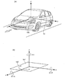
図1は、運動体と運動体に搭載された慣性センサの一例を示す図である。
角度計測装置は、運動体である走行中の車両のヨー方向の振れ角を計測するものであり、水平な仮想平面上に配置された車両の左右方向をX軸、前後方向をY軸、上下方向をZ軸とし、車両の走行中にZ軸周りのヨー角の変化量を振れ角として計測する。
図1は、運動体と運動体に搭載された慣性センサの一例を示す図である。
角度計測装置は、運動体である走行中の車両のヨー方向の振れ角を計測するものであり、水平な仮想平面上に配置された車両の左右方向をX軸、前後方向をY軸、上下方向をZ軸とし、車両の走行中にZ軸周りのヨー角の変化量を振れ角として計測する。
角度計測装置は、慣性センサ100内に構成される。慣性センサ100は、図1(a)に示すように、運動体(車両)10の重心に近い位置に設置され、慣性力(加速度、角速度)が印加された場合に、運動体10の挙動を計測できるよう、運動体10の角度(姿勢)と車両のX軸、Y軸、Z軸との関係がわかるように設置される。運動体10は、図1(b)に示すように、その左右方向(車幅方向)をX軸、前後方向をY軸、上下方向をZ軸とし、それぞれ、X軸周りをピッチ(Pitch)、Y軸周りをロール(Roll)、Z軸周りをヨー(Yaw)とする。なお、X軸、Y軸、Z軸は夫々90度の角度をなした直交座標である。
ここで、慣性センサ100の運動体10への設置は、必ずしも重力加速度の印加される軸に対して、慣性センサ100のX軸、Y軸、Z軸が水平または、垂直である必要はなく、角度をもった状態での設置でも構わない。この場合、慣性力が働かない状態(例えば、等速度運動状態)においてのセンサの角度を、運動体10の設置角度に設定する。但し、角度を持って設置された運動体10では、X軸、Y軸、Z軸は夫々、センサ素子のミスアライメントなどの誤差要因を除いては、直交することしている。
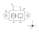
図2は、慣性センサの構成を示す図である。
慣性センサ100は、外装ケース101にセンサエレメント103と、センサ出力の信号処理を行う回路素子102とを収容している。そして、外装ケース101には、運動体10に取り付けるための取付け孔104が設けられている。センサエレメント103は、運動体10の加速度と角速度を計測するセンサ手段として、加速度センサ(Gセンサ)132と角速度センサ(ジャイロセンサ)131を有している。
慣性センサ100は、外装ケース101にセンサエレメント103と、センサ出力の信号処理を行う回路素子102とを収容している。そして、外装ケース101には、運動体10に取り付けるための取付け孔104が設けられている。センサエレメント103は、運動体10の加速度と角速度を計測するセンサ手段として、加速度センサ(Gセンサ)132と角速度センサ(ジャイロセンサ)131を有している。
加速度センサ132と角速度センサ131は、3軸の加速度と3軸の角速度を計測する。なお、センサエレメント103は、図2に示すような1個のパッケージに内包されていなくても良く、1軸以上の加速度センサと1軸以上の角速度センサをそれぞれ組み合せたものでもよい。また、1軸以上の加速度センサと1軸以上の角速度センサが複合化されたコンバインドセンサを組み合せたものでもよい。1軸以上の角速度センサと1軸以上の加速度センサは、統合化し1パッケージ化されたセンサでも、複数の単体センサでも良い。当然のことながら、角速度センサと加速度センサが統合化され1パッケージ化されていても良い。
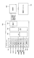
図3は、慣性センサの入出力と信号処理のブロック図であり、慣性センサ100の信号伝達構成、回路ブロック、角度算出(演算)の回路構成を示す。
センサエレメント103には、3軸の角速度センサ131と3軸の加速度センサ132が内包されており、各センサ131、132からのセンサ出力を処理するA/Dコンバータ134を経て、DSP(デジタルシグナルプロセッサー)又はマイコンなどの信号処理演算回路135に接続される。
3軸の加速度センサ132は、X軸方向の加速度Gxを検出するX軸Gセンサ、及び、Y軸方向の加速度Gyを検出するY軸Gセンサ、及び、Z軸方向の加速度Gzを検出するZ軸Gセンサを備える。3軸の角速度センサ131は、ヨー方向の角速度を計測するヨーセンサ(Yawセンサ)、及び、ロール方向の角速度を計測するロールセンサ(Rollセンサ)、及び、ピッチ方向の角速度を計測するピッチセンサ(Pitchセンサ)を備えている。
DSP、マイコンなどの信号処理演算回路135では、角速度センサ131及び加速度センサ132からの出力を所定の出力に演算、補正するとともに、温度センサ133の出力を用いてセンサ出力の補正、自己診断などの不具合検出などを行う。そして、これらのデータを通信インターフェース136を介して、マイコンなどの回路素子102に送り、回路素子102で角度算出の演算処理を行う(演算処理手段)。回路素子102は、センサ出力、演算結果、診断結果他センサに関する出力を制御用コントローラー110に送る。
回路素子102は、センサエレメント103から3軸の角速度センサ131の出力と3軸の加速度センサ132の出力を得て、これらの各出力から、ある時点において運動体10に働く各方向の慣性力と、運動体10の姿勢角度を計算する。回路素子102は、例えば、ヨーセンサのセンサ出力であるヨー方向の角速度を積分し、その積分値からヨー方向の角度を算出する。なお、慣性力と姿勢角度を算出する計算、又は演算する処理部は、センサエレメント103内、または、回路素子102内、または、制御用コントローラー110内のいずれかのDSP、マイコンなどの演算素子で処理することができ、角度算出が可能となる。回路素子102は、センサ素子103内、または制御コントローラー110内などに搭載される。回路素子102を制御コントローラー110に搭載する場合には、センサ素子103への通信時間短縮など、処理時間の短縮に有効である。
制御用コントローラー110は、予め設定された条件に基づいて基準値セット信号を回路素子102に出力する。基準値セット信号は、例えば運動体10の正確なヨー角を計測する必要があると判断した場合と、運動体10の運動状態がセンサエレメント103によって正確なヨー角を計測可能な状態である場合に出力される(基準値セット信号出力手段)。
制御用コントローラー110は、車輪速センサ、GPS、ナビゲーションシステム、カメラ他外部センサなどから、運動体10がある状態、ある位置であることを受け、そこからのヨー角の計測が必要であると判断する。また、運動体10に慣性力が働かない状態は、角速度センサ131のセンサ出力である角速度を積分しても誤差が最小限に抑えられるため、正確なヨー角を計測可能な状態であると判断する。なお、基準値セット信号の出力は、運転者の意図により行うことも可能である。これは、狭い道路やカーブ、坂の多い道路の走行や悪天候で外界認識ができず、車線内を正確に走行したい場合にも有効である。
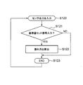
図4は、角度計測方法を説明するフローチャートである。
まず、センサエレメント103のセンサ出力が回路素子102に入力される(S120)。そして、回路素子102において、制御用コントローラー110から基準値セット信号の入力を受けたか否かが判断され(S121)、制御用コントローラー110から出力される基準値セット信号を検知した場合には(S121でYES)、運動体10の振れ角を算出する処理が行われる(S122)。
まず、センサエレメント103のセンサ出力が回路素子102に入力される(S120)。そして、回路素子102において、制御用コントローラー110から基準値セット信号の入力を受けたか否かが判断され(S121)、制御用コントローラー110から出力される基準値セット信号を検知した場合には(S121でYES)、運動体10の振れ角を算出する処理が行われる(S122)。
回路素子102は、制御用コントローラー110から出力された基準値セット信号を検知すると(信号検知手段)、基準値セット信号の入力を受けた時点からヨーセンサのセンサ出力の時間積分を開始してヨー角を算出し、そのヨー角を運動体10の振れ角とする(振れ角算出手段)。これにより、基準値セット信号の入力を受けた時点のヨー角を基準とし、その後の運動体10の運動により変化したヨー角との差分である振れ角を求めることができる。なお、ここではヨー角についての記載であるが、ロール角、ピッチ角も同様に積分演算可能である。
制御用コントローラー110は、運動体10の正確なヨー角を計測する必要がある場合に、基準値セット信号を出力する。運動体10の正確なヨー角を計測する必要があるか否かは、運動体10に搭載されたカメラで外界環境を撮像した撮像画像と、ナビゲーションシステムやGPSから取得した自車位置情報と、車輪速センサやステアリングセンサから取得した自車挙動情報の少なくとも一つに基づいて判断される。
例えば、GPSの情報が届かない場所(地下道、トンネル、ビル内駐車場、立体駐車場他)、カーブの多い、半径角が大きいことが予見され、ナビゲーションシステムの位置情報が正確に確認できない場合、あるいは、車輪速センサやステアリングセンサの情報や横滑り防止装置の情報で運動体が通常走行から逸脱した状態にある場合には、従来の停車時にリセットした零点を基準としたヨー角の算出方法では、誤差の増大が予想される。誤差が増大すると、システムが自車の走行方向を認識できなくなり、自律運転や先進運転支援システム(ADAS)の走行に支障をきたすおそれがある。
本実施例では、制御用コントローラー110において、撮像画像と自車位置情報と自車挙動情報の少なくとも一つに基づき、運動体10がこの後移動する方向を正確に把握する必要があるか否か、すなわち、運動体10の正確なヨー角を計測する必要がある状況か否かを判断し、必要があると判断した場合に基準値セット信号を出力する処理が行われる。したがって、従来は誤差の増大が予想される状況であっても、ヨー方向の振れ角を正確に計測できる。
基準値セット信号は、センサエレメント103によって正確なヨー角を計測可能な運動状態である場合、すなわち、運動体10に慣性力が働かない状態(例えば等速運動状態)である場合に出力してもよい。運動体10の運動状態が等速運動状態であるか否かは、下記条件(1)と下記条件(2)に基づいて判断される。
条件(1):角速度センサ131により計測したヨー方向の角速度及びロール方向の角速度及びピッチ方向の角速度がそれぞれ0を含む所定範囲の値であること。
条件(2):加速度センサ132により計測した前後方向の加速度GX及び左右方向の加速度GY及び上下方向の加速度GZが√(GX 2+GY 2+GZ 2)=A(Aは、1を含む所定範囲の値)の関係を満たすこと。
条件(2):加速度センサ132により計測した前後方向の加速度GX及び左右方向の加速度GY及び上下方向の加速度GZが√(GX 2+GY 2+GZ 2)=A(Aは、1を含む所定範囲の値)の関係を満たすこと。
条件(1)は、角速度センサ131の各軸(ヨー、ロール、ピッチ)のそれぞれの出力(角速度)が“0”である場合に成立し、条件(2)は、加速度センサ132の各軸(X軸,Y軸,Z軸)の値(加速度)が√(GX
2+GY
2+GZ
2)=“1” (g)(=9.8m/s2)である場合に成立する。そして、上記条件(1)と条件(2)の少なくとも一方が成立した場合に、運動体10に作用する慣性力が“0”の状態、すなわち、運動体10の運動状態が等速運動状態であると判定する。
条件(1)と条件(2)が成立した場合、運動体10への慣性力の入力は“0”となるため、算出されるヨー角は、車両の走行方向に対しての絶対角の正確な角度となり、運動中(走行中)にヨー角を正確な値に設定するセット動作が可能となる。すなわち、条件(1)または条件(2)のいずれかが成立するということは、運動体10に慣性力が働いていない“慣性力 0”の状態(等速運動状態)であるので、かかる等速運動状態で角速度センサ132のセンサ出力を基準値に設定すると、その時点から角速度を積分し得る角度(ヨー角、ロール角、ピッチ角)は、積分誤差を最小限に抑えることができ、精度の高い角度を得ることが可能となる。
なお、条件(1)における角速度センサ131の各出力“0”、または、条件(2)における 計算式の“1”は、センサのノイズ他誤差要因を含むため、ある一定範囲内でセットすることが可能である。例えば、角速度センサ131のノイズやドリフト含めた誤差は一般的に1deg/s以内と考えられるため、角速度センサ131のセット可能な出力範囲は、±1deg/sとすることが可能である。すなわち、角速度センサ131の各軸(ヨー、ロール、ピッチ)のそれぞれの出力が0±1deg/sの範囲内である場合に、条件(1)が成立していると判断する。
好ましくは、角速度センサ131の検出感度を2倍上げることで信号対雑音比(SNR)を1/2に低減することが可能となる。これらを含めて、センサ全体の精度を±0.5deg/s以下に抑えることで、角速度センサ131のセット可能な出力範囲を±0.5deg/sとし、運動体10の姿勢をより高精度化することができる。
同様に、加速度センサ132においても、ノイズやドリフト含めた誤差は一般的に20mg(19.6×10⁻²m/s2)以内と考えられるため、加速度センサ132のセット可能な範囲は、±20mgとすることが可能である。すなわち、加速度センサ132の各軸の値を用いた計算式√(GX
2+GY
2+GZ
2)の解Aが1g±20mgの範囲にあった場合に、条件(2)が成立していると判断する。なお好ましくは、加速度センサ132の検出感度を2倍上げることで信号対雑音比(SNR)を1/2に低減することが可能となる。これらを含めて、センサ全体の精度を±10mg以下に抑えることで、セット範囲を±10mgとし、運動体10のヨー方向の振れ角をより高精度化することができる。
運動体10が等速運動状態であるか否かは、上記条件(1)と下記条件(2)の少なくとも一方が成立している時間が一定時間以上であった場合とすることも可能である。これは、ノイズ等によって瞬間的に条件(1)または条件(2)を満たすおそれがあり、信頼性が確保できない可能性があるためである。なお、データのサンプリング周期はCAN通信の更新周期10ms以下が望ましい。
運動体10が等速運動状態であるか否かは、加速度センサ132により検出した加速度と角速度センサ131により検出した角速度の両方を用いて判断してもよい。慣性センサ100が、3軸の角速度と、3軸の加速度を計測できない、または計測素子がない場合でも、角速度センサの出力が“0”、X軸、Y軸の加速度センサの出力が“0”または、Z軸加速度センサの出力が“1”の場合を組合せて、慣性力“0”であるか否か(等速運動状態であるか否か)を判断する構成としても良い。慣性センサ100は、1軸以上の軸方向の加速度を計測する加速度センサと、1軸以上の軸周りの角速度を計測する角速度センサの少なくとも一方を有し、加速度センサと角度センサの少なくとも一方で計測した計測値に基づいて運動体10の運動状態が等速運動状態であるか否かを判定することができる。
自動車に横滑り防止装置やロールオーバー検知の制御システムが標準装備化されている場合がある。横滑り防止装置用の慣性センサは、1軸(ヨー)の角速度と、2軸の加速度(前後方向、左右方向加速度計測)または3軸の加速度(前後、左右、上下方向加速度)を計測している。そして、ロールオーバー検知用の慣性センサは、1軸(ロール)の角速度と、1軸の加速度(上下方向加速度計測)または2軸の加速度(上下、左右方向加速度)を計測している。
これらの横滑り防止装置用の慣性センサとロールオーバー検知用の慣性センサの出力信号を用いることで、5軸方向の慣性力(ヨー、ロール、前後、左右、上下方向加速度)が計測可能である。したがって、回路素子102で、角速度センサの出力が“0”、X軸、Y軸の加速度センサの出力が“0”または、Z軸加速度センサの出力が“1”の場合を組合せて、運動体10の慣性力“0”、すなわち、等速運動状態であると判断しても良い。なお、上記横滑り防止装置用の慣性センサやロールオーバー検知用の慣性センサを用いた角度、姿勢演算は、回路素子102内でなくても、制御用コントローラーやその他演算処理可能なマイコン、DSPで行っても良い。
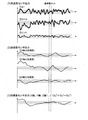
図5は、加速度センサ出力と角速度センサ出力の変化を示すタイミングチャートである。
各軸の角速度センサのセンサ出力(1)と、各軸の加速度センサのセンサ出力(2)と、加速度センサ出力の演算結果(3)とが、それぞれ所定の範囲内(図5に破線で示す上限値と下限値との間)に入った場合に、慣性力が働かない状態(例えば等速運動状態)であり、正確なヨー角を計測可能な状況であるとして、制御用コントローラー110から基準値セット信号が出力される。基準値セット信号は、各軸の角速度センサのセンサ出力(1)と、各軸の加速度センサのセンサ出力(2)と、加速度センサ出力の演算結果(3)が複数回連続して入った場合に出力されることが望ましい。これは、複数回連続して入ったことを条件とすることで、慣性力があるにも拘らず、偶然、所定の範囲に入ってしまい、そのときに角速度センサ131のセンサ出力から求めたヨー角が正しい値として設定されてしまうのを避けるためである。
各軸の角速度センサのセンサ出力(1)と、各軸の加速度センサのセンサ出力(2)と、加速度センサ出力の演算結果(3)とが、それぞれ所定の範囲内(図5に破線で示す上限値と下限値との間)に入った場合に、慣性力が働かない状態(例えば等速運動状態)であり、正確なヨー角を計測可能な状況であるとして、制御用コントローラー110から基準値セット信号が出力される。基準値セット信号は、各軸の角速度センサのセンサ出力(1)と、各軸の加速度センサのセンサ出力(2)と、加速度センサ出力の演算結果(3)が複数回連続して入った場合に出力されることが望ましい。これは、複数回連続して入ったことを条件とすることで、慣性力があるにも拘らず、偶然、所定の範囲に入ってしまい、そのときに角速度センサ131のセンサ出力から求めたヨー角が正しい値として設定されてしまうのを避けるためである。
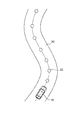
図6及び図7は、基準値セット信号が出力されるタイミングの一例を示す図である。図6は、撮像画像や自車位置情報や自車挙動情報等により基準値セット信号が出力される場合を示す。
角度計測装置は、図6に示すように、運動体(自車)10が道路20を走行中に、運動体10に搭載されたカメラで外界環境を撮像した撮像画像と、ナビゲーションシステムやGPSから取得した自車位置情報と、車輪速センサやステアリングセンサから取得した自車挙動情報の少なくとも一つに基づいて前方の道路状況を把握する。そして、道路20のカーブ手前に基準点21をセットし、運動体10が基準点21を通過する際に基準値セット信号を出力し、その後に角速度センサ131のヨーセンサから出力される角速度の積分を開始する。したがって、カーブにおける運動体10のヨー方向の振れ角を精度よく計測することができ、運動体10の高精度な自立走行や追従走行を可能とする。
角度計測装置は、図6に示すように、運動体(自車)10が道路20を走行中に、運動体10に搭載されたカメラで外界環境を撮像した撮像画像と、ナビゲーションシステムやGPSから取得した自車位置情報と、車輪速センサやステアリングセンサから取得した自車挙動情報の少なくとも一つに基づいて前方の道路状況を把握する。そして、道路20のカーブ手前に基準点21をセットし、運動体10が基準点21を通過する際に基準値セット信号を出力し、その後に角速度センサ131のヨーセンサから出力される角速度の積分を開始する。したがって、カーブにおける運動体10のヨー方向の振れ角を精度よく計測することができ、運動体10の高精度な自立走行や追従走行を可能とする。
図7は、制御コントローラーなどの時間設定により基準値セット信号が出力される場合を示す。
角度計測装置は、図7に示すように、運動体(自車)10が道路20を走行中に、運動体10に搭載されたカメラで外界環境を撮像した撮像画像と、ナビゲーションシステムやGPSから取得した自車位置情報と、車輪速センサやステアリングセンサから取得した自車挙動情報の少なくとも一つに基づいて前方の道路状況を把握する。そして、道路20上に基準点22が所定間隔をおいて連続的に配置されるように、一定の時間間隔(例えば、カメラの画像処理時間以下の50ms以下)をおいて基準点22をセットし、運動体10が基準点22を通過する際に基準値セット信号を出力し、その後に角速度センサ131のヨーセンサから出力される角速度の積分を開始する。したがって、道路20上を走行する運動体10のヨー方億の振れ角を精度よく計測することができ、運動体10の高精度な自立走行や追従走行を可能とする。また、カメラなどの処理時間間隔内での補完にも有効である。ここで、当然のことながら、本方法は、静止した運動体でも適用は可能である。
角度計測装置は、図7に示すように、運動体(自車)10が道路20を走行中に、運動体10に搭載されたカメラで外界環境を撮像した撮像画像と、ナビゲーションシステムやGPSから取得した自車位置情報と、車輪速センサやステアリングセンサから取得した自車挙動情報の少なくとも一つに基づいて前方の道路状況を把握する。そして、道路20上に基準点22が所定間隔をおいて連続的に配置されるように、一定の時間間隔(例えば、カメラの画像処理時間以下の50ms以下)をおいて基準点22をセットし、運動体10が基準点22を通過する際に基準値セット信号を出力し、その後に角速度センサ131のヨーセンサから出力される角速度の積分を開始する。したがって、道路20上を走行する運動体10のヨー方億の振れ角を精度よく計測することができ、運動体10の高精度な自立走行や追従走行を可能とする。また、カメラなどの処理時間間隔内での補完にも有効である。ここで、当然のことながら、本方法は、静止した運動体でも適用は可能である。
また、演算の終了(角速度センサの信号を積分し、角度を演算する時間)は、カメラやナビゲーションシステム等の情報をもとに、終了の信号を回路素子102に出すものとする。これは、データ量が多い場合に、回路素子102の負荷を減らすことに有効であり、演算時間が長くなり角度誤差が(角速度センサに積分による累積誤差)増大することを防ぐことに有効であるためである。
演算の終了は、悪路やスリップする走行状態、路面においては、時間的な変動が大きく、慣性力が正確に計測できない場合があるため、角度演算部102での演算処理を中止する機能を有することも可能である。この状態を検知する手段は、加速度センサ、角速度センサは勿論のこと、車輪速センサ、ステアリングセンサなどのセンサ情報をもとに、制御用コントローラー110から演算中止の命令を回路素子102に出力しても良いし、慣性センサ100の情報をもとに、慣性センサ100内の演算処理部で判断し、終了処理を行っても良い。以上のことから、慣性センサ100の出力を演算することで、運動体10の角度を、運動中でも正確に計測できる効果がある。
本実施例の角度計測装置によれば、運動体10の運動中に、GPS、カメラ、ナビゲーションシステム他で運動体10の位置や状態情報を確認し、制御用コントローラー110から回路素子102に対し、ある時点からのセンサ信号を基準値にセット(積分を開始)する信号を出し、その信号を基に処理回路で角速度センサ(ヨーセンサ)のセンサ出力を積分することで、ある時点からの運動体10の角度(振れ角)を正確に計測することができる。
本実施例の角度計測装置によれば、運動体10の運動中に、GPS、カメラ、ナビゲーションシステム他で運動体10の位置や状態情報を確認し、制御用コントローラー110から回路素子102に対し、ある時点からのセンサ信号を基準値にセット(積分を開始)する信号を出し、その信号を基に処理回路で角速度センサ(ヨーセンサ)のセンサ出力を積分することで、ある時点からの運動体10の角度(振れ角)を正確に計測することができる。
以上、本発明の実施形態について詳述したが、本発明は、前記の実施形態に限定されるものではなく、特許請求の範囲に記載された本発明の精神を逸脱しない範囲で、種々の設計変更を行うことができるものである。例えば、前記した実施の形態は本発明を分かりやすく説明するために詳細に説明したものであり、必ずしも説明した全ての構成を備えるものに限定されるものではない。また、ある実施形態の構成の一部を他の実施形態の構成に置き換えることが可能であり、また、ある実施形態の構成に他の実施形態の構成を加えることも可能である。さらに、各実施形態の構成の一部について、他の構成の追加・削除・置換をすることが可能である。
10:運動体、100:慣性センサ、101:外装ケース、102:回路素子、103:センサエレメント、104:取付け孔、110:制御コントローラー、
Claims (14)
- 運動中の運動体のヨー方向の振れ角を計測する角度計測装置であって、
運動体が運動動作の状態において基準値セット信号を受けた時点から、ヨー方向の振れ角を算出する振れ角算出手段を有することを特徴とする角度計測装置。 - 前記振れ角算出手段は、ヨー方向の角速度を積分して算出することを特徴とする請求項1に記載の角度計測装置。
- 前記振れ角算出手段は、センサ内部、もしくは、制御用コントローラー内に設定されることを特徴とする請求項2に記載の角度計測装置。
- 前記基準値セット信号は、前記制御用コントローラーから出力され、
前記振れ角算出手段は、前記基準値セット信号を受けた後のヨー角の変化量を前記振れ角として算出することを特徴とする請求項3に記載の角度計測装置。 - 前記基準値セット信号は、ナビゲーションシステム又はGPSの位置情報と、撮像画像の少なくとも一方に基づいて出力されることを特徴とする請求項4に記載の角度計測装置。
- 前記基準値セット信号は、前記制御用コントローラーから一定の時間間隔で出力されることを特徴とする請求項4に記載の角度計測装置。
- 角速度センサと加速度センサを備え、
前記基準値セット信号は、前記運動体の運動中において下記条件(1)と下記条件(2)の少なくとも一方が成立する場合に出力されることを特徴とする請求項4に記載の角度計測装置。
条件(1):前記角速度センサにより計測したヨー方向の角速度及びロール方向の角速度及びピッチ方向の角速度がそれぞれ0を含む所定範囲の値であること。
条件(2):前記加速度センサにより計測した前後方向の加速度GX及び左右方向の加速度GY及び上下方向の加速度GZが√(GX 2+GY 2+GZ 2)=A(Aは、1を含む所定範囲の値)の関係を満たすこと。 - 前記振れ角算出手段は、前記基準セット信号を受けた時点のヨー角を基準値としてセットし、該基準値からの振れ角を算出することを特徴とする請求項7に記載の角度計測装置。
- 多数軸の角速度センサと多数軸の加速度センサを有するセンサエレメントを有することを特徴とする請求項4に記載の角度計測装置。
- 角速度センサの信号を積分し、角度を演算する時間は、カメラまたはナビゲーションシステムの情報をもとに、終了することを特徴とする請求項4に記載の角度計測装置。
- 運動中の運動体のヨー方向の振れ角を計測する角度計測装置であって、
前記運動体のヨー方向の角速度を検出するヨーセンサと、
予め設定された条件に基づいて前記運動体の運動中に基準値セット信号を出力する基準値セット信号出力手段と、
前記基準値セット信号出力手段から出力される前記基準値セット信号を検知する信号検知手段と、
前記基準値セット信号を検知した時点から前記ヨーセンサのセンサ出力の積分を開始して前記運動体の振れ角を算出する振れ角算出手段と、
を有することを特徴とする角度計測装置。 - 前記振れ角算出手段は、前記基準値セット信号を検知した時点のヨー角を基準値としてセットし、該基準値からの振れ角を算出することを特徴とする請求項11に記載の角度計測装置。
- 前記基準値セット信号出力手段は、前記運動体に搭載されたカメラで外界環境を撮像した撮像画像と、ナビゲーションシステムやGPSから取得した自車位置情報と、車輪速センサやステアリングセンサから取得した自車挙動情報の少なくとも一つに基づいて前記基準値セット信号を出力することを特徴とする請求項11に記載の角度計測装置。
- 前記基準値セット信号出力手段は、前記運動体に慣性力が働かない状態(例えば等速運動状態)である場合に、前記基準値セット信号を出力することを特徴とする請求項11に記載の角度計測装置。
Priority Applications (1)
| Application Number | Priority Date | Filing Date | Title |
|---|---|---|---|
| JP2018527469A JP6594546B2 (ja) | 2016-07-15 | 2017-06-20 | 角度計測装置 |
Applications Claiming Priority (2)
| Application Number | Priority Date | Filing Date | Title |
|---|---|---|---|
| JP2016140796 | 2016-07-15 | ||
| JP2016-140796 | 2016-07-15 |
Publications (1)
| Publication Number | Publication Date |
|---|---|
| WO2018012213A1 true WO2018012213A1 (ja) | 2018-01-18 |
Family
ID=60952546
Family Applications (1)
| Application Number | Title | Priority Date | Filing Date |
|---|---|---|---|
| PCT/JP2017/022612 Ceased WO2018012213A1 (ja) | 2016-07-15 | 2017-06-20 | 角度計測装置 |
Country Status (2)
| Country | Link |
|---|---|
| JP (1) | JP6594546B2 (ja) |
| WO (1) | WO2018012213A1 (ja) |
Cited By (2)
| Publication number | Priority date | Publication date | Assignee | Title |
|---|---|---|---|---|
| WO2020158485A1 (ja) * | 2019-01-28 | 2020-08-06 | パナソニックIpマネジメント株式会社 | 複合センサおよび角速度補正方法 |
| JP2021105618A (ja) * | 2018-03-08 | 2021-07-26 | セイコーエプソン株式会社 | 慣性計測装置、移動体測位装置、システム、及び移動体 |
Citations (4)
| Publication number | Priority date | Publication date | Assignee | Title |
|---|---|---|---|---|
| JP2002107147A (ja) * | 2000-09-28 | 2002-04-10 | Aisin Seiki Co Ltd | 車両のヨーレート検出装置 |
| JP2006199242A (ja) * | 2005-01-24 | 2006-08-03 | Toyota Motor Corp | 車両の挙動制御装置 |
| JP2010127631A (ja) * | 2008-11-25 | 2010-06-10 | Honda Motor Co Ltd | 横方向挙動量検出手段のゼロ点補正装置 |
| JP2015220802A (ja) * | 2014-05-15 | 2015-12-07 | トヨタ自動車株式会社 | 電動車両 |
-
2017
- 2017-06-20 JP JP2018527469A patent/JP6594546B2/ja active Active
- 2017-06-20 WO PCT/JP2017/022612 patent/WO2018012213A1/ja not_active Ceased
Patent Citations (4)
| Publication number | Priority date | Publication date | Assignee | Title |
|---|---|---|---|---|
| JP2002107147A (ja) * | 2000-09-28 | 2002-04-10 | Aisin Seiki Co Ltd | 車両のヨーレート検出装置 |
| JP2006199242A (ja) * | 2005-01-24 | 2006-08-03 | Toyota Motor Corp | 車両の挙動制御装置 |
| JP2010127631A (ja) * | 2008-11-25 | 2010-06-10 | Honda Motor Co Ltd | 横方向挙動量検出手段のゼロ点補正装置 |
| JP2015220802A (ja) * | 2014-05-15 | 2015-12-07 | トヨタ自動車株式会社 | 電動車両 |
Cited By (3)
| Publication number | Priority date | Publication date | Assignee | Title |
|---|---|---|---|---|
| JP2021105618A (ja) * | 2018-03-08 | 2021-07-26 | セイコーエプソン株式会社 | 慣性計測装置、移動体測位装置、システム、及び移動体 |
| JP7092229B2 (ja) | 2018-03-08 | 2022-06-28 | セイコーエプソン株式会社 | 慣性計測装置、移動体測位装置、システム、及び移動体 |
| WO2020158485A1 (ja) * | 2019-01-28 | 2020-08-06 | パナソニックIpマネジメント株式会社 | 複合センサおよび角速度補正方法 |
Also Published As
| Publication number | Publication date |
|---|---|
| JPWO2018012213A1 (ja) | 2019-03-14 |
| JP6594546B2 (ja) | 2019-10-23 |
Similar Documents
| Publication | Publication Date | Title |
|---|---|---|
| CN107084743B (zh) | 利用gnss/ins数据的六自由度惯性测量单元的偏移和失准补偿 | |
| JP7073052B2 (ja) | ビークルの角度位置を測定するシステムおよび方法 | |
| CN101473193B (zh) | 姿势角检测装置与姿势角检测方法 | |
| US7463953B1 (en) | Method for determining a tilt angle of a vehicle | |
| JP3375268B2 (ja) | ナビゲーション装置 | |
| CN110221333A (zh) | 一种车载ins/od组合导航系统的量测误差补偿方法 | |
| KR101878685B1 (ko) | 지도 정보를 이용한 차량 측위 시스템 및 방법 | |
| JP2013145168A (ja) | 車載用ジャイロの角速度誤差補正装置 | |
| JPH10168810A (ja) | 道路縦断プロファイル測定装置 | |
| CN111902693A (zh) | 用于校准装备于车辆的陀螺仪的方法 | |
| JP6632727B2 (ja) | 角度計測装置 | |
| JP2004138605A (ja) | 車両のフロート角度の決定方法及び装置 | |
| JP6594546B2 (ja) | 角度計測装置 | |
| EP2831599B1 (en) | Inertial sensor enhancement | |
| JP2004125689A (ja) | 自立航法用位置算出システム | |
| JP3033363B2 (ja) | 自走台車の絶対位置検出方法 | |
| JP5352922B2 (ja) | 角速度算出装置、ナビゲーション装置 | |
| JPH11295335A (ja) | 移動体の位置検出装置 | |
| US9791277B2 (en) | Apparatus and method for measuring velocity of moving object in a navigation system | |
| JP2013178136A (ja) | 取付け角度補正装置 | |
| JP2843904B2 (ja) | 車両用慣性航法装置 | |
| JP5891120B2 (ja) | 速度算出装置、速度算出方法、速度算出プログラム、および記録媒体 | |
| JP2878498B2 (ja) | 角加速度検出装置 | |
| JPH102747A (ja) | ナビゲーション装置 | |
| JP6454857B2 (ja) | 姿勢検出装置及び姿勢検出方法 |
Legal Events
| Date | Code | Title | Description |
|---|---|---|---|
| ENP | Entry into the national phase |
Ref document number: 2018527469 Country of ref document: JP Kind code of ref document: A |
|
| 121 | Ep: the epo has been informed by wipo that ep was designated in this application |
Ref document number: 17827343 Country of ref document: EP Kind code of ref document: A1 |
|
| NENP | Non-entry into the national phase |
Ref country code: DE |
|
| 122 | Ep: pct application non-entry in european phase |
Ref document number: 17827343 Country of ref document: EP Kind code of ref document: A1 |