WO2018012132A1 - Method for manufacturing molten metal plated steel strip and continuous molten metal plating equipment - Google Patents
Method for manufacturing molten metal plated steel strip and continuous molten metal plating equipment Download PDFInfo
- Publication number
- WO2018012132A1 WO2018012132A1 PCT/JP2017/020142 JP2017020142W WO2018012132A1 WO 2018012132 A1 WO2018012132 A1 WO 2018012132A1 JP 2017020142 W JP2017020142 W JP 2017020142W WO 2018012132 A1 WO2018012132 A1 WO 2018012132A1
- Authority
- WO
- WIPO (PCT)
- Prior art keywords
- molten metal
- steel strip
- angle
- gas
- nozzle
- Prior art date
Links
- 229910000831 Steel Inorganic materials 0.000 title claims abstract description 116
- 239000010959 steel Substances 0.000 title claims abstract description 116
- 239000002184 metal Substances 0.000 title claims abstract description 87
- 238000004519 manufacturing process Methods 0.000 title claims abstract description 28
- 238000007747 plating Methods 0.000 title claims description 53
- 238000000034 method Methods 0.000 title abstract description 20
- 238000007664 blowing Methods 0.000 claims abstract description 3
- 239000007789 gas Substances 0.000 claims description 83
- 238000002347 injection Methods 0.000 claims description 16
- 239000007924 injection Substances 0.000 claims description 16
- 239000011261 inert gas Substances 0.000 claims description 5
- 238000002844 melting Methods 0.000 claims description 4
- 230000008018 melting Effects 0.000 claims description 4
- 239000012535 impurity Substances 0.000 claims description 3
- 238000005507 spraying Methods 0.000 claims description 2
- 230000037303 wrinkles Effects 0.000 description 36
- XLYOFNOQVPJJNP-UHFFFAOYSA-N water Substances O XLYOFNOQVPJJNP-UHFFFAOYSA-N 0.000 description 29
- 229910001335 Galvanized steel Inorganic materials 0.000 description 16
- 239000008397 galvanized steel Substances 0.000 description 16
- 238000009826 distribution Methods 0.000 description 14
- 230000000694 effects Effects 0.000 description 7
- 230000007547 defect Effects 0.000 description 6
- 230000008569 process Effects 0.000 description 6
- 239000000203 mixture Substances 0.000 description 5
- 210000004894 snout Anatomy 0.000 description 5
- 238000001816 cooling Methods 0.000 description 4
- 230000003647 oxidation Effects 0.000 description 4
- 238000007254 oxidation reaction Methods 0.000 description 4
- 238000005275 alloying Methods 0.000 description 3
- 238000000137 annealing Methods 0.000 description 3
- 230000008859 change Effects 0.000 description 3
- 238000000576 coating method Methods 0.000 description 3
- 238000005096 rolling process Methods 0.000 description 3
- 229910018137 Al-Zn Inorganic materials 0.000 description 2
- 229910018573 Al—Zn Inorganic materials 0.000 description 2
- XKRFYHLGVUSROY-UHFFFAOYSA-N Argon Chemical compound [Ar] XKRFYHLGVUSROY-UHFFFAOYSA-N 0.000 description 2
- IJGRMHOSHXDMSA-UHFFFAOYSA-N Atomic nitrogen Chemical compound N#N IJGRMHOSHXDMSA-UHFFFAOYSA-N 0.000 description 2
- CURLTUGMZLYLDI-UHFFFAOYSA-N Carbon dioxide Chemical compound O=C=O CURLTUGMZLYLDI-UHFFFAOYSA-N 0.000 description 2
- 239000011248 coating agent Substances 0.000 description 2
- 230000000052 comparative effect Effects 0.000 description 2
- 238000010586 diagram Methods 0.000 description 2
- 238000005246 galvanizing Methods 0.000 description 2
- 238000007689 inspection Methods 0.000 description 2
- 239000007788 liquid Substances 0.000 description 2
- 238000005259 measurement Methods 0.000 description 2
- 238000002156 mixing Methods 0.000 description 2
- 230000003746 surface roughness Effects 0.000 description 2
- BKUKXOMYGPYFJJ-UHFFFAOYSA-N 2-ethylsulfanyl-1h-benzimidazole;hydrobromide Chemical compound Br.C1=CC=C2NC(SCC)=NC2=C1 BKUKXOMYGPYFJJ-UHFFFAOYSA-N 0.000 description 1
- 0 O=NC*1CCC1 Chemical compound O=NC*1CCC1 0.000 description 1
- 230000009471 action Effects 0.000 description 1
- 229910052786 argon Inorganic materials 0.000 description 1
- 239000001569 carbon dioxide Substances 0.000 description 1
- 229910002092 carbon dioxide Inorganic materials 0.000 description 1
- 238000011156 evaluation Methods 0.000 description 1
- 239000001307 helium Substances 0.000 description 1
- 229910052734 helium Inorganic materials 0.000 description 1
- SWQJXJOGLNCZEY-UHFFFAOYSA-N helium atom Chemical compound [He] SWQJXJOGLNCZEY-UHFFFAOYSA-N 0.000 description 1
- 230000006872 improvement Effects 0.000 description 1
- 238000009434 installation Methods 0.000 description 1
- 230000007246 mechanism Effects 0.000 description 1
- 229910052757 nitrogen Inorganic materials 0.000 description 1
- 238000000053 physical method Methods 0.000 description 1
- 238000005554 pickling Methods 0.000 description 1
- 238000001953 recrystallisation Methods 0.000 description 1
- 230000004043 responsiveness Effects 0.000 description 1
- 238000007665 sagging Methods 0.000 description 1
- 238000007711 solidification Methods 0.000 description 1
- 230000008023 solidification Effects 0.000 description 1
- 239000007921 spray Substances 0.000 description 1
- 239000000126 substance Substances 0.000 description 1
- 230000001629 suppression Effects 0.000 description 1
- 229910052725 zinc Inorganic materials 0.000 description 1
Images


Classifications
-
- C—CHEMISTRY; METALLURGY
- C22—METALLURGY; FERROUS OR NON-FERROUS ALLOYS; TREATMENT OF ALLOYS OR NON-FERROUS METALS
- C22C—ALLOYS
- C22C18/00—Alloys based on zinc
- C22C18/04—Alloys based on zinc with aluminium as the next major constituent
-
- C—CHEMISTRY; METALLURGY
- C22—METALLURGY; FERROUS OR NON-FERROUS ALLOYS; TREATMENT OF ALLOYS OR NON-FERROUS METALS
- C22C—ALLOYS
- C22C21/00—Alloys based on aluminium
- C22C21/10—Alloys based on aluminium with zinc as the next major constituent
-
- C—CHEMISTRY; METALLURGY
- C23—COATING METALLIC MATERIAL; COATING MATERIAL WITH METALLIC MATERIAL; CHEMICAL SURFACE TREATMENT; DIFFUSION TREATMENT OF METALLIC MATERIAL; COATING BY VACUUM EVAPORATION, BY SPUTTERING, BY ION IMPLANTATION OR BY CHEMICAL VAPOUR DEPOSITION, IN GENERAL; INHIBITING CORROSION OF METALLIC MATERIAL OR INCRUSTATION IN GENERAL
- C23C—COATING METALLIC MATERIAL; COATING MATERIAL WITH METALLIC MATERIAL; SURFACE TREATMENT OF METALLIC MATERIAL BY DIFFUSION INTO THE SURFACE, BY CHEMICAL CONVERSION OR SUBSTITUTION; COATING BY VACUUM EVAPORATION, BY SPUTTERING, BY ION IMPLANTATION OR BY CHEMICAL VAPOUR DEPOSITION, IN GENERAL
- C23C2/00—Hot-dipping or immersion processes for applying the coating material in the molten state without affecting the shape; Apparatus therefor
- C23C2/003—Apparatus
- C23C2/0034—Details related to elements immersed in bath
- C23C2/00342—Moving elements, e.g. pumps or mixers
- C23C2/00344—Means for moving substrates, e.g. immersed rollers or immersed bearings
-
- C—CHEMISTRY; METALLURGY
- C23—COATING METALLIC MATERIAL; COATING MATERIAL WITH METALLIC MATERIAL; CHEMICAL SURFACE TREATMENT; DIFFUSION TREATMENT OF METALLIC MATERIAL; COATING BY VACUUM EVAPORATION, BY SPUTTERING, BY ION IMPLANTATION OR BY CHEMICAL VAPOUR DEPOSITION, IN GENERAL; INHIBITING CORROSION OF METALLIC MATERIAL OR INCRUSTATION IN GENERAL
- C23C—COATING METALLIC MATERIAL; COATING MATERIAL WITH METALLIC MATERIAL; SURFACE TREATMENT OF METALLIC MATERIAL BY DIFFUSION INTO THE SURFACE, BY CHEMICAL CONVERSION OR SUBSTITUTION; COATING BY VACUUM EVAPORATION, BY SPUTTERING, BY ION IMPLANTATION OR BY CHEMICAL VAPOUR DEPOSITION, IN GENERAL
- C23C2/00—Hot-dipping or immersion processes for applying the coating material in the molten state without affecting the shape; Apparatus therefor
- C23C2/003—Apparatus
- C23C2/0038—Apparatus characterised by the pre-treatment chambers located immediately upstream of the bath or occurring locally before the dipping process
- C23C2/004—Snouts
-
- C—CHEMISTRY; METALLURGY
- C23—COATING METALLIC MATERIAL; COATING MATERIAL WITH METALLIC MATERIAL; CHEMICAL SURFACE TREATMENT; DIFFUSION TREATMENT OF METALLIC MATERIAL; COATING BY VACUUM EVAPORATION, BY SPUTTERING, BY ION IMPLANTATION OR BY CHEMICAL VAPOUR DEPOSITION, IN GENERAL; INHIBITING CORROSION OF METALLIC MATERIAL OR INCRUSTATION IN GENERAL
- C23C—COATING METALLIC MATERIAL; COATING MATERIAL WITH METALLIC MATERIAL; SURFACE TREATMENT OF METALLIC MATERIAL BY DIFFUSION INTO THE SURFACE, BY CHEMICAL CONVERSION OR SUBSTITUTION; COATING BY VACUUM EVAPORATION, BY SPUTTERING, BY ION IMPLANTATION OR BY CHEMICAL VAPOUR DEPOSITION, IN GENERAL
- C23C2/00—Hot-dipping or immersion processes for applying the coating material in the molten state without affecting the shape; Apparatus therefor
- C23C2/04—Hot-dipping or immersion processes for applying the coating material in the molten state without affecting the shape; Apparatus therefor characterised by the coating material
- C23C2/06—Zinc or cadmium or alloys based thereon
-
- C—CHEMISTRY; METALLURGY
- C23—COATING METALLIC MATERIAL; COATING MATERIAL WITH METALLIC MATERIAL; CHEMICAL SURFACE TREATMENT; DIFFUSION TREATMENT OF METALLIC MATERIAL; COATING BY VACUUM EVAPORATION, BY SPUTTERING, BY ION IMPLANTATION OR BY CHEMICAL VAPOUR DEPOSITION, IN GENERAL; INHIBITING CORROSION OF METALLIC MATERIAL OR INCRUSTATION IN GENERAL
- C23C—COATING METALLIC MATERIAL; COATING MATERIAL WITH METALLIC MATERIAL; SURFACE TREATMENT OF METALLIC MATERIAL BY DIFFUSION INTO THE SURFACE, BY CHEMICAL CONVERSION OR SUBSTITUTION; COATING BY VACUUM EVAPORATION, BY SPUTTERING, BY ION IMPLANTATION OR BY CHEMICAL VAPOUR DEPOSITION, IN GENERAL
- C23C2/00—Hot-dipping or immersion processes for applying the coating material in the molten state without affecting the shape; Apparatus therefor
- C23C2/04—Hot-dipping or immersion processes for applying the coating material in the molten state without affecting the shape; Apparatus therefor characterised by the coating material
- C23C2/12—Aluminium or alloys based thereon
-
- C—CHEMISTRY; METALLURGY
- C23—COATING METALLIC MATERIAL; COATING MATERIAL WITH METALLIC MATERIAL; CHEMICAL SURFACE TREATMENT; DIFFUSION TREATMENT OF METALLIC MATERIAL; COATING BY VACUUM EVAPORATION, BY SPUTTERING, BY ION IMPLANTATION OR BY CHEMICAL VAPOUR DEPOSITION, IN GENERAL; INHIBITING CORROSION OF METALLIC MATERIAL OR INCRUSTATION IN GENERAL
- C23C—COATING METALLIC MATERIAL; COATING MATERIAL WITH METALLIC MATERIAL; SURFACE TREATMENT OF METALLIC MATERIAL BY DIFFUSION INTO THE SURFACE, BY CHEMICAL CONVERSION OR SUBSTITUTION; COATING BY VACUUM EVAPORATION, BY SPUTTERING, BY ION IMPLANTATION OR BY CHEMICAL VAPOUR DEPOSITION, IN GENERAL
- C23C2/00—Hot-dipping or immersion processes for applying the coating material in the molten state without affecting the shape; Apparatus therefor
- C23C2/14—Removing excess of molten coatings; Controlling or regulating the coating thickness
- C23C2/16—Removing excess of molten coatings; Controlling or regulating the coating thickness using fluids under pressure, e.g. air knives
- C23C2/18—Removing excess of molten coatings from elongated material
- C23C2/20—Strips; Plates
-
- C—CHEMISTRY; METALLURGY
- C23—COATING METALLIC MATERIAL; COATING MATERIAL WITH METALLIC MATERIAL; CHEMICAL SURFACE TREATMENT; DIFFUSION TREATMENT OF METALLIC MATERIAL; COATING BY VACUUM EVAPORATION, BY SPUTTERING, BY ION IMPLANTATION OR BY CHEMICAL VAPOUR DEPOSITION, IN GENERAL; INHIBITING CORROSION OF METALLIC MATERIAL OR INCRUSTATION IN GENERAL
- C23C—COATING METALLIC MATERIAL; COATING MATERIAL WITH METALLIC MATERIAL; SURFACE TREATMENT OF METALLIC MATERIAL BY DIFFUSION INTO THE SURFACE, BY CHEMICAL CONVERSION OR SUBSTITUTION; COATING BY VACUUM EVAPORATION, BY SPUTTERING, BY ION IMPLANTATION OR BY CHEMICAL VAPOUR DEPOSITION, IN GENERAL
- C23C2/00—Hot-dipping or immersion processes for applying the coating material in the molten state without affecting the shape; Apparatus therefor
- C23C2/34—Hot-dipping or immersion processes for applying the coating material in the molten state without affecting the shape; Apparatus therefor characterised by the shape of the material to be treated
- C23C2/36—Elongated material
- C23C2/40—Plates; Strips
Definitions
- the present invention relates to a method for producing a molten metal-plated steel strip and a continuous molten metal plating facility, and more particularly to gas wiping for adjusting the amount of molten metal deposited on the surface of the steel strip (hereinafter also referred to as “plated deposit”). It is.
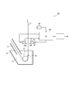
- the steel strip S annealed in a continuous annealing furnace in a reducing atmosphere passes through the snout 10 and continuously into the molten metal bath 14 in the plating tank 12. To be introduced. Thereafter, the steel strip S is pulled up above the molten metal bath 14 via the sink roll 16 and the support roll 18 in the molten metal bath 14, adjusted to a predetermined plating thickness by the gas wiping nozzles 20A and 20B, and then cooled. Then, it is led to the subsequent process.
- the gas wiping nozzles 20 ⁇ / b> A and 20 ⁇ / b> B are arranged above the plating tank 12 so as to face each other with the steel strip S interposed therebetween, and spray gas toward both surfaces of the steel strip S from the injection port.
- the gas wiping nozzles 20A and 20B are generally configured wider than the steel strip width in order to cope with various steel strip widths and to correspond to positional deviations in the width direction when the steel strip is pulled up. It extends to the outside from the part.
- Patent Document 1 describes a method of making hot water wrinkles inconspicuous by changing the surface properties and rolling conditions of a temper rolling roll during temper rolling, which is a process after plating.
- Patent Document 2 before the steel sheet is introduced into the hot dip galvanizing bath, the surface roughness of the steel sheet is adjusted according to the amount of plating applied using a skin pass mill, a tension leveler, etc. to suppress the generation of hot water wrinkles. How to do is described.
- Patent Document 1 improves minor hot water wrinkles, but has no effect on severe hot water wrinkles.
- the method disclosed in Patent Document 2 has a problem in terms of cost because it is necessary to install a skin pass mill, a tension leveler, etc. in the pre-process of the hot dip galvanizing bath.
- the ideal surface roughness is difficult to obtain due to chemical and physical changes in the galvanized film accompanying pickling and recrystallization in the pretreatment equipment and annealing furnace. It is considered difficult to sufficiently suppress the occurrence.
- the present invention provides a method for producing a molten metal plated steel strip and a continuous molten metal plating facility capable of sufficiently suppressing generation of hot water wrinkles and producing a high quality molten metal plated steel strip at low cost.
- the purpose is to do.
- the present inventors paid attention to the installation angle of the gas wiping nozzle.
- the gas wiping nozzle is installed so that the gas injection direction is substantially perpendicular to the steel strip (that is, the horizontal direction), but gas wiping is performed so that the gas injection direction is a predetermined angle or more downward with respect to the horizontal direction.
- the present inventors have found that the generation of hot water wrinkles can be sufficiently suppressed by installing the nozzles at an inclination.
- the gist configuration of the present invention completed based on the above findings is as follows.
- a steel strip is continuously immersed in a molten metal bath, By blowing gas from a pair of gas wiping nozzles placed across the steel strip to the steel strip pulled up from the molten metal bath, adjusting the amount of molten metal deposited on both sides of the steel strip,
- a method for producing a molten metal plated steel strip that continuously produces a molten metal plated steel strip The gas wiping nozzle is installed downward with respect to the horizontal plane so that the angle ⁇ between the injection port portion and the horizontal plane is 10 degrees or more and 75 degrees or less, and the header pressure P of the gas wiping nozzle is less than 30 kPa.
- a method for producing a hot-dip metal-plated steel strip is produced by blowing gas from a pair of gas wiping nozzles placed across the steel strip to the steel strip pulled up from the molten metal bath, adjusting the amount of molten metal deposited on both sides of the steel strip,
- the component of the molten metal contains Al: 1.0 to 10% by mass, Mg: 0.2 to 1% by mass, Ni: 0 to 0.1% by mass, and the balance consisting of Zn and inevitable impurities (1)
- the temperature T (° C.) of the gas immediately after being discharged from the tip of the gas wiping nozzle is such that T M ⁇ 150 ⁇ T ⁇ T M +250 in relation to the melting point T M (° C.) of the molten metal.
- a plating tank containing molten metal and forming a molten metal bath;
- a pair of gas wiping nozzles arranged across a steel strip that is continuously pulled up from the molten metal bath, spraying gas toward the steel strip, and adjusting the amount of plating on both sides of the steel strip,
- the gas wiping nozzle is installed downward with respect to the horizontal plane such that an angle ⁇ between the injection port portion and the horizontal plane is 10 degrees or more and 75 degrees or less, and the header pressure P of the gas wiping nozzle is Is a continuous molten metal plating facility characterized in that is set to less than 30 kPa.
- (6) a memory in which the relationship between the header pressure P and a suitable angle ⁇ is recorded in the range where the header pressure P is less than 30 kPa; An angle detector for detecting the angle ⁇ ; A nozzle driving device for changing the angle ⁇ ; A control device for the nozzle driving device; The control device reads out a suitable angle ⁇ corresponding to the changed pressure P from the memory when the operating condition is changed and the header pressure P is changed, and the angle detector
- the continuous molten metal plating facility according to (5) wherein when the detected angle does not satisfy the preferred angle ⁇ , the nozzle driving device is controlled so that the detected angle is the preferred angle ⁇ . .
- a surface appearance detector for observing the surface appearance of the steel strip after wiping;
- a nozzle driving device for changing the angle ⁇ ;
- a control device for the nozzle driving device;
- the control device controls the nozzle driving device based on an output from the surface appearance detector to finely adjust the angle ⁇ , as described in (5) above. .
- the manufacturing method and continuous molten metal plating equipment of the present invention the production of hot metal wrinkles can be sufficiently suppressed, and a high quality molten metal plated steel strip can be manufactured at low cost.
- (A) And (B) is sectional drawing perpendicular
- plating facility a method for manufacturing a molten metal plated steel strip and a continuous molten metal plating facility 100 (hereinafter also simply referred to as “plating facility”) according to an embodiment of the present invention will be described.
- a plating facility 100 of the present embodiment includes a snout 10, a plating tank 12 that contains molten metal, a sink roll 16, and a support roll 18.
- the snout 10 is a member having a rectangular cross section perpendicular to the traveling direction of the steel strip, which defines a space through which the steel strip S passes, and its tip is immersed in a molten metal bath 14 formed in the plating tank 12. Yes.
- the steel strip S annealed in a continuous annealing furnace in a reducing atmosphere passes through the snout 10 and is continuously introduced into the molten metal bath 14 in the plating tank 12.
- the steel strip S is pulled up above the molten metal bath 14 via the sink roll 16 and the support roll 18 in the molten metal bath 14 and adjusted to a predetermined plating thickness by the pair of gas wiping nozzles 20A and 20B. Then, it is cooled and led to a subsequent process.
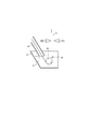
- a pair of gas wiping nozzles 20A and 20B are disposed above the plating tank 12 with a steel strip S. Are arranged opposite to each other.
- the nozzle 20A blows gas toward the steel strip S from an injection port 26 (nozzle slit) extending in the plate width direction of the steel strip at the tip thereof, and adjusts the amount of plating adhered to the surface of the steel strip.
- the nozzle 20A is usually configured to be longer than the steel strip width in order to correspond to various steel strip widths and to the positional deviation in the width direction when the steel strip is pulled up to the outer side of the widthwise end of the steel strip. It extends.
- the nozzle 20 ⁇ / b> A includes a nozzle header 22 and an upper nozzle member 24 ⁇ / b> A and a lower nozzle member 24 ⁇ / b> B connected to the nozzle header 22.
- the tip portions of the upper and lower nozzle members 24A and 24B face each other in parallel in a cross-sectional view perpendicular to the steel strip S to form a gas injection port 26 (nozzle slit) (parallel in FIG. 3B). portion).
- the injection port 26 extends in the plate width direction of the steel strip S.
- the vertical cross-sectional shape of the nozzle 20A is a tapered shape that tapers toward the tip.
- the thickness of the tip portions of the upper and lower nozzle members 24A and 24B may be about 1 to 3 mm.
- the opening width (nozzle gap) of the injection port is not particularly limited, but can be about 0.5 to 3.0 mm.
- a gas supplied from a gas supply mechanism passes through the inside of the header 22, further passes through a gas flow path defined by the upper and lower nozzle members 24 ⁇ / b> A and 24 ⁇ / b> B, and is injected from the injection port 26, and the surface of the steel strip S Be blown into.
- the other nozzle 20B has the same configuration.
- the steel strip S is continuously immersed in the molten metal bath 14, and the steel strip S is disposed between the steel strip S pulled up from the molten metal bath 14.
- a gas is sprayed from a pair of gas wiping nozzles 20A and 20B to adjust the amount of molten metal adhering to both surfaces of the steel strip S to continuously produce a molten metal plated steel strip.
- the cause of generation of the hot water wrinkles described above there is generation of initial unevenness at a point (stagnation point) where the wiping gas collides with the molten metal surface.
- the cause of the initial unevenness is that the molten metal is irregularly formed on the steel strip due to one or both of (1) vibration of the collision pressure of the wiping gas and (2) uneven viscosity due to oxidation / cooling of the molten metal. It is thought to be flowing. Therefore, it is considered that suppressing the phenomenon (1) and / or (2) leads to suppression of generation of hot water wrinkles.
- the gas wiping nozzles 20A and 20B are installed downward with respect to the horizontal plane so that the angle ⁇ formed by the injection port portion with the horizontal plane is 10 degrees or more.
- the angle ⁇ is set to 10 degrees or more.
- generation of hot water wrinkles can be sufficiently suppressed.
- the angle ⁇ exceeds 75 degrees, the generation of hot water wrinkles cannot be suppressed due to the generation of an unstable pressure pool described later, so the angle ⁇ is set to 75 degrees or less.
- “the angle ⁇ formed by the injection port portion with the horizontal plane” means that the upper nozzle member 24A and the lower nozzle member 24B face each other as shown in FIGS. 3 (A) and 3 (B).
- the header pressure P of the wiping nozzle is less than 30 kPa. This is because if the header pressure P is set to 30 kPa or more, the wind speed when the wiping gas collides with the bath surface increases, and bath surface splash frequently occurs. In addition, when there is much target plating adhesion amount, the header pressure P will be made small, but in that case, the above-mentioned hot water wrinkles are likely to occur. However, by setting the angle ⁇ of the gas wiping nozzle as described above, the generation of hot water wrinkles can be sufficiently suppressed even with a small header pressure P of less than 30 kPa.
- the header pressure P is less than 10 kPa, the collision pressure at the edge of the steel strip is particularly weak, so the amount of adhesion at the edge becomes too thick, and the amount of adhesion may be uneven in the width direction of the steel strip. Therefore, the header pressure P is preferably 10 kPa or more.
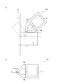
- the present invention is characterized in that, by controlling the angle ⁇ of the wiping nozzle in this way, the range of the collision pressure acting on the steel strip S is expanded and the generation of hot water wrinkles is suppressed.
- the wiping nozzle is installed so that the gas injection direction is substantially perpendicular to the steel strip S, the collision pressure increases. Therefore, when the collision pressure was measured under conditions where hot water wrinkles were generated, it was found that the collision pressure oscillated with time. This is because, particularly in the case of low gas pressure, the potential core does not develop sufficiently in the parallel part inside the nozzle (see FIG. 3B), and the potential core is disturbed by the outside air ejected from the nozzle. Conceivable.
- b is the opening width (nozzle gap) of the nozzle slit
- y / b on the horizontal axis indicates the ratio of both.
- y ⁇ 0 means the lower side from the gas jet center (on the hot dip plating tank side)
- y> 0 means the upper side from the gas jet center (on the anti-hot dip plating tank side).
- the collision pressure ratio on the vertical axis represents the ratio of the collision pressure under other conditions when the maximum pressure of the collision pressure distribution curve at the set nozzle angle ⁇ is used as the reference (1.0).
- the “gas jet center” means the vertical center of the vertical range in which the gas collides with the steel strip.
- the impact pressure distribution (d) is a gentler pressure distribution than (b) and the half-value width is expanded, but the appearance of the steel strip after plating deteriorated again. .
- the reason why the appearance deteriorated at this time is that when the distance d between the tip of the wiping nozzle and the steel strip is constant and the angle ⁇ of the wiping nozzle is increased, the gap between the upper portion of the wiping nozzle and the steel strip S becomes extremely narrow. It is estimated that the wiping gas is not discharged well from the gap between the wiping gas and the steel strip S, resulting in an unstable pressure pool (see FIG. 5).
- the angle ⁇ is set to 75 degrees or less.
- the upper limit of the angle ⁇ is preferably set as follows in relation to the header pressure P from the viewpoint of sufficiently suppressing the generation of hot water wrinkles. That is, when the header pressure P is 0 to 10 kPa, ⁇ ⁇ 75 degrees is preferable, and when the header pressure P is greater than 10 kPa and less than 20 kPa, ⁇ ⁇ 60 degrees is preferable. Is preferably 20 ⁇ 30 kPa, ⁇ ⁇ 50 degrees is preferable.
- the temperature T (° C.) of the gas immediately after being discharged from the tip of the gas wiping nozzle satisfies T M ⁇ 150 ⁇ T ⁇ T M +250 in relation to the melting point T M (° C.) of the molten metal. It is preferable to control.
- the gas temperature T is controlled within the above range, the cooling and solidification of the molten metal can be suppressed, so that viscosity unevenness hardly occurs and the generation of hot water wrinkles can be suppressed.
- the gas temperature T is less than T M ⁇ 150 ° C. and is too low, the fluidity of the molten metal is not affected, so that there is no effect in suppressing the generation of hot water wrinkles. Further, if the temperature of the wiping gas is too high at T M + 250 ° C., alloying is promoted and the appearance of the steel sheet is deteriorated.
- the gas injected from the nozzles 20A and 20B is preferably an inert gas.
- an inert gas By using an inert gas, oxidation of the molten metal on the surface of the steel strip can be prevented, so that viscosity unevenness of the molten metal can be further suppressed.
- the inert gas include, but are not limited to, nitrogen, argon, helium, carbon dioxide and the like.
- the molten metal component preferably contains Al: 1.0 to 10% by mass, Mg: 0.2 to 1% by mass, Ni: 0 to 0.1% by mass, and the balance is composed of Zn and inevitable impurities. .
- Mg 0.2 to 1% by mass
- Ni 0 to 0.1% by mass
- the balance is composed of Zn and inevitable impurities.
- hot-dip galvanized steel strip produced by the production method and plating equipment of the present invention examples include hot-dip galvanized steel sheets, which are plated steel sheets (GI) that are not subjected to alloying after hot-dip galvanization. Any of the plated steel sheets (GA) subjected to alloying treatment is included.
- control is performed so that the angle ⁇ of the wiping nozzle becomes a more preferable range or value within the range of 10 to 75 degrees according to the value of the header pressure P of the gas wiping nozzle.
- the preferred range of the wiping nozzle angle ⁇ in the range of 10 to 75 degrees varies depending on the value of the header pressure P. Therefore, the hot water wrinkle can be more reliably and sufficiently suppressed by adjusting the angle ⁇ as follows.
- angle detector 40 is a device that detects angle ⁇ of nozzles 20A and 20B, and is adjusted so that nozzles 20A and 20B display 0 degrees in a state of being parallel to the bath surface. Yes.
- Examples of the angle detector 40 include a physical method such as a protractor, a type using a laser, and a type applying the electrical characteristics of a special liquid, but is not particularly limited thereto.
- the nozzle drive device 42 includes a nozzle rotation motor and can change the angle ⁇ .
- the memory 44 stores a correspondence table between the header pressure P and the nozzle angle ⁇ , that is, information regarding a preferable range of the nozzle angle ⁇ corresponding to the header pressure P.
- the angle ⁇ is 10 to 75 degrees
- the angle ⁇ is 10 to 60 degrees
- the header pressure P is When the pressure is greater than 20 kPa and less than 30 kPa, a correspondence table in which the angle ⁇ is 10 to 50 degrees is recorded in the memory 44.
- the header pressure P can be appropriately determined from the operating conditions such as the line speed, the thickness of the steel strip, the target plating adhesion amount, the distance between the tip of the wiping nozzle and the steel strip. Therefore, when operating under a predetermined operating condition or when changing the operating condition, the control device 46 reads a suitable angle ⁇ (preferred range or target value) corresponding to the determined header pressure P from the memory 44. . The control device 46 determines the required angle change amount from the angle ⁇ read from the memory 44 and the output value of the angle detector 40, and controls the nozzle driving device 42. The nozzle driving device 42 rotates the nozzles 20 ⁇ / b> A and 20 ⁇ / b> B to a predetermined angle according to the output value of the control device 46.
- a suitable angle ⁇ (preferred range or target value) corresponding to the determined header pressure P from the memory 44.
- the control device 46 determines the required angle change amount from the angle ⁇ read from the memory 44 and the output value of the angle detector 40, and controls the
- the control device 46 reads a suitable angle ⁇ corresponding to the changed pressure P from the memory 44 and detects it by the angle detector 40.
- the nozzle driving device 42 is controlled to set the detected angle to the preferred angle ⁇ .
- a surface appearance detector 48 is a device that detects an appearance of a steel strip surface after passing through a gas wiping nozzle, for example, an arithmetic mean waviness Wa, and is provided, for example, above the gas wiping nozzle 20A.
- the surface appearance detector 48 continuously photographs the surface of the steel strip after passing through the gas wiping nozzle, and inputs the information to the control device 46.
- Examples of the form of the surface appearance detector 48 include a non-contact 3D roughness meter using a laser, but are not particularly limited.
- the control device 46 finely adjusts the angle ⁇ by controlling the nozzle driving device 42 based on the output of the surface appearance detector 48. Specifically, the following control is performed.
- Fail Galvanized steel sheet with a lot of splash defects (0 ⁇ Wa, 1.30 ⁇ S)
- Fail Galvanized steel sheet with large hot wrinkles visible (1.50 ⁇ Wa, S ⁇ 1.30)
- Fail Galvanized steel sheet that can visually check small hot water wrinkles (1.00 ⁇ Wa ⁇ 1.50, S ⁇ 1.30)
- Pass Beautiful galvanized steel sheet with no visible wrinkles (0.50 ⁇ Wa ⁇ 1.00, S ⁇ 1.30)
- Pass Very beautiful galvanized steel sheet with no visible wrinkles (0 ⁇ Wa ⁇ 0.50, S ⁇ 1.30)
- Wa is the value of the arithmetic average waviness Wa [ ⁇ m] measured based on the standard of JIS B0601-2001.
- the splash mixing rate S is the ratio [%] of the steel strip length determined as having a splash defect in the inspection process to the
- Wa measured by the detector is 0.50 ⁇ Wa ⁇ 1.00 (ie, acceptable “ ⁇ ”)
- fine adjustment is performed so that the wiping nozzle angle ⁇ is increased, and then Wa to be measured is 0 ⁇ Wa ⁇ 0.50 (that is, “accepted” ⁇ ”). This is because, when the wiping nozzle angle ⁇ is increased, the vibration of the collision pressure of the wiping gas is further reduced.
- the measurement location by the surface appearance detector 48 is desirably a position where the steel strip S passes through the wiping nozzle and the molten metal on the steel strip surface is solidified.
- the position where the molten metal on the surface of the steel strip is hardened for example, a position 40 m or more downstream of the wiping nozzle is desirable.
- the measurement position is preferably immediately after the molten metal is hardened. Therefore, for example, a position 70 m or less downstream of the wiping nozzle is desirable.
- nozzle height H is too low, a large amount of bath surface splash occurs, so a height of 200 mm or more is desirable.
- the nozzle height H and the distance d between the gas wiping nozzle tip and the steel strip shown in FIG. 3A do not necessarily have to be linked to the wiping nozzle angle ⁇ , but depending on the target adhesion amount and the bath surface splash amount. It is preferable to change appropriately.
- a production test for the hot dip galvanized steel strip was conducted.
- the plating equipment shown in FIG. 1 was used.
- a gas wiping nozzle having a nozzle gap of 1.2 mm was used.
- the composition of the plating bath, the temperature T of the plating bath, the melting point T M of the plating bath, the angle ⁇ of the nozzle, the wiping gas pressure P, the gas type, and the temperature T of the wiping gas are shown in Table 1.
- the distance d between the nozzle tip and the steel strip was 15 mm.
- the height H from the bath surface of the nozzle was 350 mm.
- a method of supplying a gas pressurized to a predetermined pressure by a compressor was adopted.
- a steel strip having a thickness of 1.2 mm and a plate width of 1000 mm was passed at a steel strip speed L (line speed) of 2 m / s to produce a hot dip galvanized steel strip.
- the manufacturing method and continuous molten metal plating equipment of the present invention the production of hot metal wrinkles can be sufficiently suppressed, and a high quality molten metal plated steel strip can be manufactured at low cost.
Abstract
Description
(1)溶融金属浴に連続的に鋼帯を浸漬し、
前記溶融金属浴から引き上げられる鋼帯に、該鋼帯を挟んで配置される一対のガスワイピングノズルからガスを吹き付けて、該鋼帯の両面の溶融金属の付着量を調整して、
連続的に溶融金属めっき鋼帯を製造する溶融金属めっき鋼帯の製造方法であって、
前記ガスワイピングノズルは、その噴射口部分が水平面となす角度θが10度以上75度以下となるように、該水平面に対して下向きに設置され、前記ガスワイピングノズルのヘッダ圧力Pが30kPa未満であることを特徴とする溶融金属めっき鋼帯の製造方法。 The gist configuration of the present invention completed based on the above findings is as follows.
(1) A steel strip is continuously immersed in a molten metal bath,
By blowing gas from a pair of gas wiping nozzles placed across the steel strip to the steel strip pulled up from the molten metal bath, adjusting the amount of molten metal deposited on both sides of the steel strip,
A method for producing a molten metal plated steel strip that continuously produces a molten metal plated steel strip,
The gas wiping nozzle is installed downward with respect to the horizontal plane so that the angle θ between the injection port portion and the horizontal plane is 10 degrees or more and 75 degrees or less, and the header pressure P of the gas wiping nozzle is less than 30 kPa. A method for producing a hot-dip metal-plated steel strip.
前記溶融金属浴から連続的に引き上げられる鋼帯を挟んで配置され、前記鋼帯に向けてガスを吹き付け、前記鋼帯の両面のめっき付着量を調整する一対のガスワイピングノズルと、
を有し、前記ガスワイピングノズルは、その噴射口部分が水平面となす角度θが10度以上75度以下となるように、該水平面に対して下向きに設置され、前記ガスワイピングノズルのヘッダ圧力Pが30kPa未満に設定されることを特徴とする連続溶融金属めっき設備。 (5) a plating tank containing molten metal and forming a molten metal bath;
A pair of gas wiping nozzles arranged across a steel strip that is continuously pulled up from the molten metal bath, spraying gas toward the steel strip, and adjusting the amount of plating on both sides of the steel strip,
The gas wiping nozzle is installed downward with respect to the horizontal plane such that an angle θ between the injection port portion and the horizontal plane is 10 degrees or more and 75 degrees or less, and the header pressure P of the gas wiping nozzle is Is a continuous molten metal plating facility characterized in that is set to less than 30 kPa.
前記角度θを検出する角度検出器と、
前記角度θを変更するためのノズル駆動装置と、
前記ノズル駆動装置の制御装置と、
をさらに有し、前記制御装置は、操業条件が変更されて前記ヘッダ圧力Pが変更された場合に、変更後の圧力Pに対応する好適な角度θを前記メモリから読み出し、前記角度検出器により検出された検出角度が前記好適な角度θを満たさない場合に、前記ノズル駆動装置を制御して、前記検出角度を前記好適な角度θとする、上記(5)に記載の連続溶融金属めっき設備。 (6) a memory in which the relationship between the header pressure P and a suitable angle θ is recorded in the range where the header pressure P is less than 30 kPa;
An angle detector for detecting the angle θ;
A nozzle driving device for changing the angle θ;
A control device for the nozzle driving device;
The control device reads out a suitable angle θ corresponding to the changed pressure P from the memory when the operating condition is changed and the header pressure P is changed, and the angle detector The continuous molten metal plating facility according to (5), wherein when the detected angle does not satisfy the preferred angle θ, the nozzle driving device is controlled so that the detected angle is the preferred angle θ. .
前記角度θを変更するためのノズル駆動装置と、
前記ノズル駆動装置の制御装置と、
をさらに有し、前記制御装置は、前記表面外観検出器からの出力に基づいて前記ノズル駆動装置を制御して、前記角度θを微調整する、上記(5)に記載の連続溶融金属めっき設備。 (7) a surface appearance detector for observing the surface appearance of the steel strip after wiping;
A nozzle driving device for changing the angle θ;
A control device for the nozzle driving device;
And the control device controls the nozzle driving device based on an output from the surface appearance detector to finely adjust the angle θ, as described in (5) above. .
××:不合格=スプラッシュ欠陥が多量に発生している亜鉛めっき鋼板(0<Wa,1.30≦S)
×:不合格=目視で大きな湯ジワが確認できる亜鉛めっき鋼板(1.50<Wa, S<1.30)
△:不合格=目視で小さな湯ジワが確認できる亜鉛めっき鋼板(1.00<Wa≦1.50, S<1.30)
○:合格=目視で湯ジワが確認できない美麗な亜鉛めっき鋼板(0.50<Wa≦1.00, S<1.30)
◎:合格=目視で湯ジワが確認できない非常に美麗な亜鉛めっき鋼板(0<Wa≦0.50, S<1.30)
なお、Waは、JIS B0601-2001の規格に基づいて測定した算術平均うねりWa[μm]の値である。スプラッシュ混入率Sは、各製造条件で通過した鋼帯長さに対する、検査工程でスプラッシュ欠陥ありと判定された鋼帯長さの比率[%]である。 Regarding the surface appearance of the steel strip, acceptance / rejection shall be judged according to the following criteria.
XX: Fail = Galvanized steel sheet with a lot of splash defects (0 <Wa, 1.30 ≦ S)
×: Fail = Galvanized steel sheet with large hot wrinkles visible (1.50 <Wa, S <1.30)
△: Fail = Galvanized steel sheet that can visually check small hot water wrinkles (1.00 <Wa ≦ 1.50, S <1.30)
○: Pass = Beautiful galvanized steel sheet with no visible wrinkles (0.50 <Wa ≦ 1.00, S <1.30)
◎: Pass = Very beautiful galvanized steel sheet with no visible wrinkles (0 <Wa ≦ 0.50, S <1.30)
Wa is the value of the arithmetic average waviness Wa [μm] measured based on the standard of JIS B0601-2001. The splash mixing rate S is the ratio [%] of the steel strip length determined as having a splash defect in the inspection process to the steel strip length passed under each manufacturing condition.
××:不合格=スプラッシュ欠陥が多量に発生している亜鉛めっき鋼板(0<Wa,1.30≦S)
×:不合格=目視で大きな湯ジワが確認できる亜鉛めっき鋼板(1.50<Wa, S<1.30)
△:不合格=目視で小さな湯ジワが確認できる亜鉛めっき鋼板(1.00<Wa≦1.50, S<1.30)
○:合格=目視で湯ジワが確認できない美麗な亜鉛めっき鋼板(0.50<Wa≦1.00, S<1.30)
◎:合格=目視で湯ジワが確認できない非常に美麗な亜鉛めっき鋼板(0<Wa≦0.50, S<1.30)
なお、Waは、JIS B0601-2001の規格に基づいて測定した算術平均うねりWa[μm]の値である。スプラッシュ混入率Sは、各製造条件で通過した鋼帯長さに対する、検査工程でスプラッシュ欠陥ありと判定された鋼帯長さの比率[%]である。 Moreover, the external appearance of the manufactured hot dip galvanized steel strip and the total plating adhesion amount of both surfaces were evaluated. About the external appearance evaluation of the steel plate, the acceptability was judged according to the following criteria. The results are shown in Table 1.
XX: Fail = Galvanized steel sheet with a lot of splash defects (0 <Wa, 1.30 ≦ S)
×: Fail = Galvanized steel sheet with large hot wrinkles visible (1.50 <Wa, S <1.30)
△: Fail = Galvanized steel sheet that can visually check small hot water wrinkles (1.00 <Wa ≦ 1.50, S <1.30)
○: Pass = Beautiful galvanized steel sheet with no visible wrinkles (0.50 <Wa ≦ 1.00, S <1.30)
◎: Pass = Very beautiful galvanized steel sheet with no visible wrinkles (0 <Wa ≦ 0.50, S <1.30)
Wa is the value of the arithmetic average waviness Wa [μm] measured based on the standard of JIS B0601-2001. The splash mixing rate S is the ratio [%] of the steel strip length determined as having a splash defect in the inspection process to the steel strip length passed under each manufacturing condition.

10 スナウト
12 めっき槽
14 溶融金属浴
16 シンクロール
18 サポートロール
20A,20B ガスワイピングノズル
22 ノズルヘッダ
24A 上ノズル部材
24B 下ノズル部材
26 噴射口
40 角度検出器
42 ノズル駆動装置
44 メモリ
46 制御装置
48 表面外観検出器
S 鋼帯 DESCRIPTION OF
Claims (7)
- 溶融金属浴に連続的に鋼帯を浸漬し、
前記溶融金属浴から引き上げられる鋼帯に、該鋼帯を挟んで配置される一対のガスワイピングノズルからガスを吹き付けて、該鋼帯の両面の溶融金属の付着量を調整して、
連続的に溶融金属めっき鋼帯を製造する溶融金属めっき鋼帯の製造方法であって、
前記ガスワイピングノズルは、その噴射口部分が水平面となす角度θが10度以上75度以下となるように、該水平面に対して下向きに設置され、前記ガスワイピングノズルのヘッダ圧力Pが30kPa未満であることを特徴とする溶融金属めっき鋼帯の製造方法。 Immerse the steel strip continuously in the molten metal bath,
By blowing gas from a pair of gas wiping nozzles placed across the steel strip to the steel strip pulled up from the molten metal bath, adjusting the amount of molten metal deposited on both sides of the steel strip,
A method for producing a molten metal plated steel strip that continuously produces a molten metal plated steel strip,
The gas wiping nozzle is installed downward with respect to the horizontal plane so that the angle θ between the injection port portion and the horizontal plane is 10 degrees or more and 75 degrees or less, and the header pressure P of the gas wiping nozzle is less than 30 kPa. A method for producing a hot-dip metal-plated steel strip. - 前記溶融金属の成分は、Al:1.0~10質量%、Mg:0.2~1質量%、Ni:0~0.1質量%を含有し、残部がZn及び不可避的不純物からなる請求項1に記載の溶融金属めっき鋼帯の製造方法。 The molten metal component according to claim 1, wherein the molten metal component contains Al: 1.0 to 10% by mass, Mg: 0.2 to 1% by mass, Ni: 0 to 0.1% by mass, with the balance being Zn and inevitable impurities. A method for producing a metal-plated steel strip.
- 前記ガスワイピングノズルの先端から吐出した直後の前記ガスの温度T(℃)が、前記溶融金属の融点TM(℃)との関係で、TM-150≦T≦TM+250を満たすように制御される請求項1又は2に記載の溶融金属めっき鋼帯の製造方法。 The temperature T (° C.) of the gas immediately after being discharged from the tip of the gas wiping nozzle satisfies T M −150 ≦ T ≦ T M +250 in relation to the melting point T M (° C.) of the molten metal. The manufacturing method of the molten metal plating steel strip of Claim 1 or 2 controlled.
- 前記ガスが不活性ガスである請求項1~3のいずれか一項に記載の溶融金属めっき鋼帯の製造方法。 The method for producing a molten metal-plated steel strip according to any one of claims 1 to 3, wherein the gas is an inert gas.
- 溶融金属を収容し、溶融金属浴を形成しためっき槽と、
前記溶融金属浴から連続的に引き上げられる鋼帯を挟んで配置され、前記鋼帯に向けてガスを吹き付け、前記鋼帯の両面のめっき付着量を調整する一対のガスワイピングノズルと、
を有し、前記ガスワイピングノズルは、その噴射口部分が水平面となす角度θが10度以上75度以下となるように、該水平面に対して下向きに設置され、前記ガスワイピングノズルのヘッダ圧力Pが30kPa未満に設定されることを特徴とする連続溶融金属めっき設備。 A plating tank containing molten metal and forming a molten metal bath;
A pair of gas wiping nozzles arranged across a steel strip that is continuously pulled up from the molten metal bath, spraying gas toward the steel strip, and adjusting the amount of plating on both sides of the steel strip,
The gas wiping nozzle is installed downward with respect to the horizontal plane such that an angle θ between the injection port portion and the horizontal plane is 10 degrees or more and 75 degrees or less, and the header pressure P of the gas wiping nozzle is Is a continuous molten metal plating facility characterized in that is set to less than 30 kPa. - 前記ヘッダ圧力Pが30kPa未満の範囲で、ヘッダ圧力Pと好適な角度θとの関係を記録したメモリと、
前記角度θを検出する角度検出器と、
前記角度θを変更するためのノズル駆動装置と、
前記ノズル駆動装置の制御装置と、
をさらに有し、前記制御装置は、操業条件が変更されて前記ヘッダ圧力Pが変更された場合に、変更後の圧力Pに対応する好適な角度θを前記メモリから読み出し、前記角度検出器により検出された検出角度が前記好適な角度θを満たさない場合に、前記ノズル駆動装置を制御して、前記検出角度を前記好適な角度θとする、請求項5に記載の連続溶融金属めっき設備。 A memory in which a relationship between the header pressure P and a suitable angle θ is recorded in the range where the header pressure P is less than 30 kPa;
An angle detector for detecting the angle θ;
A nozzle driving device for changing the angle θ;
A control device for the nozzle driving device;
The control device reads out a suitable angle θ corresponding to the changed pressure P from the memory when the operating condition is changed and the header pressure P is changed, and the angle detector The continuous molten metal plating facility according to claim 5, wherein when the detected angle does not satisfy the preferable angle θ, the nozzle driving device is controlled to set the detected angle to the preferable angle θ. - ワイピング後の前記鋼帯の表面外観を観察する表面外観検出器と、
前記角度θを変更するためのノズル駆動装置と、
前記ノズル駆動装置の制御装置と、
をさらに有し、前記制御装置は、前記表面外観検出器からの出力に基づいて前記ノズル駆動装置を制御して、前記角度θを微調整する、請求項5に記載の連続溶融金属めっき設備。 A surface appearance detector for observing the surface appearance of the steel strip after wiping;
A nozzle driving device for changing the angle θ;
A control device for the nozzle driving device;
6. The continuous molten metal plating facility according to claim 5, further comprising: controlling the nozzle driving device based on an output from the surface appearance detector to finely adjust the angle θ.
Priority Applications (8)
| Application Number | Priority Date | Filing Date | Title |
|---|---|---|---|
| US16/316,424 US11104983B2 (en) | 2016-07-13 | 2017-05-30 | Method of producing hot-dip metal coated steel strip and continuous hot-dip metal coating apparatus |
| KR1020197002523A KR20190022766A (en) | 2016-07-13 | 2017-05-30 | METHOD OF MANUFACTURING MOLDED METAL PLATED KINGDOM AND MOLDED METAL PLATING APPARATUS |
| MX2019000468A MX2019000468A (en) | 2016-07-13 | 2017-05-30 | Method for manufacturing molten metal plated steel strip and continuous molten metal plating equipment. |
| EP17827265.4A EP3486351A1 (en) | 2016-07-13 | 2017-05-30 | Method for manufacturing molten metal plated steel strip and continuous molten metal plating equipment |
| AU2017296667A AU2017296667A1 (en) | 2016-07-13 | 2017-05-30 | Method for manufacturing molten metal plated steel strip and continuous molten metal plating equipment |
| CN201780042945.1A CN109477198A (en) | 2016-07-13 | 2017-05-30 | The manufacturing method and continuous molten metal plating equipment of molten metal coated steel strip |
| KR1020217017392A KR102405526B1 (en) | 2016-07-13 | 2017-05-30 | Method of producing hot-dip metal coated steel strip and continuous hot-dip metal coating apparatus |
| AU2020204123A AU2020204123B2 (en) | 2016-07-13 | 2020-06-19 | Method for manufacturing molten metal plated steel strip and continuous molten metal plating equipment |
Applications Claiming Priority (2)
| Application Number | Priority Date | Filing Date | Title |
|---|---|---|---|
| JP2016138823A JP6372527B2 (en) | 2016-07-13 | 2016-07-13 | Manufacturing method of molten metal plating steel strip and continuous molten metal plating equipment |
| JP2016-138823 | 2016-07-13 |
Publications (1)
| Publication Number | Publication Date |
|---|---|
| WO2018012132A1 true WO2018012132A1 (en) | 2018-01-18 |
Family
ID=60951755
Family Applications (1)
| Application Number | Title | Priority Date | Filing Date |
|---|---|---|---|
| PCT/JP2017/020142 WO2018012132A1 (en) | 2016-07-13 | 2017-05-30 | Method for manufacturing molten metal plated steel strip and continuous molten metal plating equipment |
Country Status (8)
| Country | Link |
|---|---|
| US (1) | US11104983B2 (en) |
| EP (1) | EP3486351A1 (en) |
| JP (1) | JP6372527B2 (en) |
| KR (2) | KR20190022766A (en) |
| CN (1) | CN109477198A (en) |
| AU (2) | AU2017296667A1 (en) |
| MX (1) | MX2019000468A (en) |
| WO (1) | WO2018012132A1 (en) |
Cited By (2)
| Publication number | Priority date | Publication date | Assignee | Title |
|---|---|---|---|---|
| JP6638872B1 (en) * | 2018-08-22 | 2020-01-29 | Jfeスチール株式会社 | Method for producing hot-dip coated steel strip and continuous hot-dip metal plating equipment |
| WO2020039869A1 (en) * | 2018-08-22 | 2020-02-27 | Jfeスチール株式会社 | Method for manufacturing hot-dip metal plated steel strip, and continuous hot-dip metal plating facility |
Families Citing this family (2)
| Publication number | Priority date | Publication date | Assignee | Title |
|---|---|---|---|---|
| JP6863330B2 (en) * | 2018-04-13 | 2021-04-21 | Jfeスチール株式会社 | Injection nozzle adjustment method and injection direction confirmation device |
| US11384419B2 (en) * | 2019-08-30 | 2022-07-12 | Micromaierials Llc | Apparatus and methods for depositing molten metal onto a foil substrate |
Citations (5)
| Publication number | Priority date | Publication date | Assignee | Title |
|---|---|---|---|---|
| JPH06184717A (en) * | 1992-12-21 | 1994-07-05 | Nippon Steel Corp | Method for controlling coating rate of hot-dip metal coating |
| JP2001279415A (en) * | 2000-03-31 | 2001-10-10 | Nisshin Steel Co Ltd | Device for controlling plating sticking amount |
| JP2011068951A (en) * | 2009-09-25 | 2011-04-07 | Jfe Steel Corp | Coating weight control device for continuous hot dip metal plating |
| JP2014055307A (en) * | 2012-09-11 | 2014-03-27 | Jfe Steel Corp | Wiping method for continuously molten metal-plated steel strip |
| WO2016056178A1 (en) * | 2014-10-08 | 2016-04-14 | Jfeスチール株式会社 | Continuous hot-dip metal plating method, hot-dip zinc-plated steel strip, and continuous hot-dip metal plating equipment |
Family Cites Families (9)
| Publication number | Priority date | Publication date | Assignee | Title |
|---|---|---|---|---|
| GB1131951A (en) * | 1965-06-08 | 1968-10-30 | Hitachi Ltd | Method of and apparatus for continuous hot dip metal coating |
| US3459587A (en) * | 1967-02-02 | 1969-08-05 | United States Steel Corp | Method of controlling coating thickness |
| US3607366A (en) | 1968-11-14 | 1971-09-21 | Yawata Iron & Steel Co | Removal of excess molten metal coatings by gas blast without ripple formations on coated surfaces |
| US3736174A (en) * | 1971-12-16 | 1973-05-29 | Steel Corp | Varying angle of gas impingement in gas knife process for removing excess coating |
| US3932683A (en) | 1972-10-10 | 1976-01-13 | Inland Steel Company | Control of coating thickness of hot-dip metal coating |
| JPS5521564A (en) | 1978-08-04 | 1980-02-15 | Kawasaki Steel Corp | Preparation of melted zinc plated steel plate for sheath plate |
| JPS60258458A (en) | 1984-06-06 | 1985-12-20 | Mitsubishi Heavy Ind Ltd | Hot dipping apparatus |
| JP2004027263A (en) | 2002-06-24 | 2004-01-29 | Sumitomo Metal Ind Ltd | Hot dip galvanized steel sheet having excellent surface appearance and method of producing the same |
| JP5470932B2 (en) | 2009-03-13 | 2014-04-16 | Jfeスチール株式会社 | Hot-dip metal-plated steel strip manufacturing equipment and hot-metal-plated steel strip manufacturing method |
-
2016
- 2016-07-13 JP JP2016138823A patent/JP6372527B2/en active Active
-
2017
- 2017-05-30 US US16/316,424 patent/US11104983B2/en active Active
- 2017-05-30 MX MX2019000468A patent/MX2019000468A/en unknown
- 2017-05-30 CN CN201780042945.1A patent/CN109477198A/en active Pending
- 2017-05-30 AU AU2017296667A patent/AU2017296667A1/en not_active Abandoned
- 2017-05-30 EP EP17827265.4A patent/EP3486351A1/en active Pending
- 2017-05-30 KR KR1020197002523A patent/KR20190022766A/en active Application Filing
- 2017-05-30 KR KR1020217017392A patent/KR102405526B1/en active IP Right Grant
- 2017-05-30 WO PCT/JP2017/020142 patent/WO2018012132A1/en unknown
-
2020
- 2020-06-19 AU AU2020204123A patent/AU2020204123B2/en active Active
Patent Citations (5)
| Publication number | Priority date | Publication date | Assignee | Title |
|---|---|---|---|---|
| JPH06184717A (en) * | 1992-12-21 | 1994-07-05 | Nippon Steel Corp | Method for controlling coating rate of hot-dip metal coating |
| JP2001279415A (en) * | 2000-03-31 | 2001-10-10 | Nisshin Steel Co Ltd | Device for controlling plating sticking amount |
| JP2011068951A (en) * | 2009-09-25 | 2011-04-07 | Jfe Steel Corp | Coating weight control device for continuous hot dip metal plating |
| JP2014055307A (en) * | 2012-09-11 | 2014-03-27 | Jfe Steel Corp | Wiping method for continuously molten metal-plated steel strip |
| WO2016056178A1 (en) * | 2014-10-08 | 2016-04-14 | Jfeスチール株式会社 | Continuous hot-dip metal plating method, hot-dip zinc-plated steel strip, and continuous hot-dip metal plating equipment |
Cited By (3)
| Publication number | Priority date | Publication date | Assignee | Title |
|---|---|---|---|---|
| JP6638872B1 (en) * | 2018-08-22 | 2020-01-29 | Jfeスチール株式会社 | Method for producing hot-dip coated steel strip and continuous hot-dip metal plating equipment |
| WO2020039869A1 (en) * | 2018-08-22 | 2020-02-27 | Jfeスチール株式会社 | Method for manufacturing hot-dip metal plated steel strip, and continuous hot-dip metal plating facility |
| US11802329B2 (en) | 2018-08-22 | 2023-10-31 | Jfe Steel Corporation | Method of producing hot-dip metal coated steel strip and continuous hot-dip metal coating line |
Also Published As
| Publication number | Publication date |
|---|---|
| CN109477198A (en) | 2019-03-15 |
| AU2020204123A1 (en) | 2020-07-09 |
| EP3486351A4 (en) | 2019-05-22 |
| KR20190022766A (en) | 2019-03-06 |
| EP3486351A1 (en) | 2019-05-22 |
| AU2020204123B2 (en) | 2021-12-16 |
| JP2018009220A (en) | 2018-01-18 |
| KR20210071100A (en) | 2021-06-15 |
| US20190300997A1 (en) | 2019-10-03 |
| MX2019000468A (en) | 2019-04-01 |
| AU2017296667A1 (en) | 2019-01-31 |
| JP6372527B2 (en) | 2018-08-15 |
| KR102405526B1 (en) | 2022-06-03 |
| US11104983B2 (en) | 2021-08-31 |
Similar Documents
| Publication | Publication Date | Title |
|---|---|---|
| AU2020204123B2 (en) | Method for manufacturing molten metal plated steel strip and continuous molten metal plating equipment | |
| KR101910756B1 (en) | Continuous hot-dip metal coating method, galvanized steel strip, and continuous hot-dip metal coating facility | |
| US11866829B2 (en) | Device and method for manufacturing a coated metal strip with improved appearance by adjusting a coating thickness using gas jet wiping | |
| US11802329B2 (en) | Method of producing hot-dip metal coated steel strip and continuous hot-dip metal coating line | |
| JP6500846B2 (en) | Method of manufacturing hot-dip metallized steel strip and continuous hot-dip metal plating equipment | |
| JP5565368B2 (en) | Wiping apparatus and hot dipping apparatus using the same | |
| JP6414360B2 (en) | Manufacturing method of molten metal plated steel strip | |
| JP4857906B2 (en) | Manufacturing method of molten metal plated steel strip | |
| JP6638872B1 (en) | Method for producing hot-dip coated steel strip and continuous hot-dip metal plating equipment | |
| JP6635086B2 (en) | Manufacturing method of hot-dip galvanized steel strip | |
| JP5386779B2 (en) | Method and apparatus for manufacturing hot-dip galvanized steel sheet | |
| JP6394578B2 (en) | Manufacturing method of molten metal plating steel strip and continuous molten metal plating equipment | |
| JP2020190005A (en) | Method for manufacturing hot-dip metal coated steel strip, and continuous hot-dip metal coating equipment | |
| WO2023037881A1 (en) | Molten metal-plated steel strip production method | |
| JP6870659B2 (en) | Gas wiping nozzle for hot metal plating equipment, gas wiping method for hot metal plating, and manufacturing method for hot metal plated steel sheet | |
| JP2007070664A (en) | Hot dip metal coated steel strip manufacturing method |
Legal Events
| Date | Code | Title | Description |
|---|---|---|---|
| 121 | Ep: the epo has been informed by wipo that ep was designated in this application |
Ref document number: 17827265 Country of ref document: EP Kind code of ref document: A1 |
|
| NENP | Non-entry into the national phase |
Ref country code: DE |
|
| ENP | Entry into the national phase |
Ref document number: 20197002523 Country of ref document: KR Kind code of ref document: A |
|
| ENP | Entry into the national phase |
Ref document number: 2017296667 Country of ref document: AU Date of ref document: 20170530 Kind code of ref document: A |
|
| ENP | Entry into the national phase |
Ref document number: 2017827265 Country of ref document: EP Effective date: 20190213 |