WO2018008627A1 - 衛星測位システム及び衛星測位方法 - Google Patents
衛星測位システム及び衛星測位方法 Download PDFInfo
- Publication number
- WO2018008627A1 WO2018008627A1 PCT/JP2017/024469 JP2017024469W WO2018008627A1 WO 2018008627 A1 WO2018008627 A1 WO 2018008627A1 JP 2017024469 W JP2017024469 W JP 2017024469W WO 2018008627 A1 WO2018008627 A1 WO 2018008627A1
- Authority
- WO
- WIPO (PCT)
- Prior art keywords
- marker
- satellite positioning
- orientation
- moving body
- unit
- Prior art date
- Legal status (The legal status is an assumption and is not a legal conclusion. Google has not performed a legal analysis and makes no representation as to the accuracy of the status listed.)
- Ceased
Links
Images









Classifications
-
- G—PHYSICS
- G01—MEASURING; TESTING
- G01C—MEASURING DISTANCES, LEVELS OR BEARINGS; SURVEYING; NAVIGATION; GYROSCOPIC INSTRUMENTS; PHOTOGRAMMETRY OR VIDEOGRAMMETRY
- G01C15/00—Surveying instruments or accessories not provided for in groups G01C1/00 - G01C13/00
-
- G—PHYSICS
- G01—MEASURING; TESTING
- G01S—RADIO DIRECTION-FINDING; RADIO NAVIGATION; DETERMINING DISTANCE OR VELOCITY BY USE OF RADIO WAVES; LOCATING OR PRESENCE-DETECTING BY USE OF THE REFLECTION OR RERADIATION OF RADIO WAVES; ANALOGOUS ARRANGEMENTS USING OTHER WAVES
- G01S19/00—Satellite radio beacon positioning systems; Determining position, velocity or attitude using signals transmitted by such systems
- G01S19/38—Determining a navigation solution using signals transmitted by a satellite radio beacon positioning system
- G01S19/39—Determining a navigation solution using signals transmitted by a satellite radio beacon positioning system the satellite radio beacon positioning system transmitting time-stamped messages, e.g. GPS [Global Positioning System], GLONASS [Global Orbiting Navigation Satellite System] or GALILEO
- G01S19/42—Determining position
- G01S19/43—Determining position using carrier phase measurements, e.g. kinematic positioning; using long or short baseline interferometry
-
- G—PHYSICS
- G01—MEASURING; TESTING
- G01S—RADIO DIRECTION-FINDING; RADIO NAVIGATION; DETERMINING DISTANCE OR VELOCITY BY USE OF RADIO WAVES; LOCATING OR PRESENCE-DETECTING BY USE OF THE REFLECTION OR RERADIATION OF RADIO WAVES; ANALOGOUS ARRANGEMENTS USING OTHER WAVES
- G01S19/00—Satellite radio beacon positioning systems; Determining position, velocity or attitude using signals transmitted by such systems
- G01S19/01—Satellite radio beacon positioning systems transmitting time-stamped messages, e.g. GPS [Global Positioning System], GLONASS [Global Orbiting Navigation Satellite System] or GALILEO
- G01S19/13—Receivers
- G01S19/24—Acquisition or tracking or demodulation of signals transmitted by the system
- G01S19/26—Acquisition or tracking or demodulation of signals transmitted by the system involving a sensor measurement for aiding acquisition or tracking
Definitions
- the present invention relates to positioning using a GNSS (Global Navigation Satellite System), and more particularly to a satellite positioning system and a satellite positioning method using a single carrier phase positioning (PPP) method.
- GNSS Global Navigation Satellite System
- PPP single carrier phase positioning
- RTK Real-Time Kinematic
- PPP single carrier phase positioning
- PPP-AR PPP Ambiguity Resolution
- the PPP method and the PPP-AR method are referred to as the PPP method, except when both are compared and contrasted).
- the PPP system has the advantage that it can achieve the same level of accuracy as the RTK system while not requiring a reference station.
- the PPP method requires initialization processing for estimating a number of parameters such as errors in satellite orbits and satellite clocks, signal delay due to passing through the ionosphere and troposphere, and carrier phase bias.
- Non-Patent Documents 1 to 3 See Non-Patent Documents 1 to 3)
- the present invention has been made based on such circumstances, and a system and method that can reduce the time required for initialization processing in satellite positioning using a marker installed on the earth, It is an object of the present invention to provide a method capable of accurately measuring or evaluating a position and / or posture. Also provided is a system or method for determining marker posture error.
- the satellite positioning system is A mobile unit having a satellite positioning unit, a marker detection unit, and a calculation unit; A marker whose position and orientation in the earth fixed coordinate system are measured in advance, The calculation unit calculates the position of the moving body in the fixed earth coordinate system based on the position and orientation of the marker detected by the marker detection unit, The satellite positioning unit receives information on the position of the moving object calculated by the calculation unit, and executes a satellite positioning process.
- the marker detection unit may include an imaging device that captures an image of the marker.
- a mobile unit having a satellite positioning unit, a marker detection unit, and a calculation unit; A plurality of markers whose positions in the earth fixed coordinate system are measured in advance, The calculation unit calculates the position of the moving body in the fixed earth coordinate system based on the positions of the plurality of markers detected by the marker detection unit, The satellite positioning unit receives information on the position of the moving object calculated by the calculation unit, and executes a satellite positioning process.
- the satellite positioning method includes: Measuring in advance the position of the marker in the fixed earth coordinate system, or the posture of the marker; Detecting the marker by a marker detection unit mounted on the moving body, and calculating a position of the moving body in the earth fixed coordinate system based on the marker; Supplying information on the position of the mobile body in the fixed earth coordinate system to a satellite positioning unit mounted on the mobile body, and executing satellite positioning processing; Is provided.
- the method for measuring the position and orientation of the marker includes: A method of measuring the position and orientation of a marker fixed on the ground by a mobile body having a satellite positioning unit, a marker detection unit, and a calculation unit, Obtaining a position of the mobile body in a fixed earth coordinate system; Moving the moving body along an arbitrary route; During the movement of the moving body, the marker detection unit observes the marker at each of a plurality of points, measures the relative position and relative orientation of the marker with respect to the marker detection unit, and based on the measurement result, Calculating a relative position of the moving body at the observation point with respect to the marker; Estimating the position and orientation of the marker in the fixed earth coordinate system using the position of the moving object in the earth fixed coordinate system and the calculated relative position of the moving object with respect to the marker at each observation point.
- the distance between the position of the moving body in the earth fixed coordinate system at each observation point and the calculated relative position of the moving body with respect to the marker is calculated, and
- the position and orientation of the marker in the earth fixed coordinate system that minimizes the evaluation function based on the sum of the distances can be used as the estimated value.
- the method for measuring the position and orientation of the marker includes: A method of measuring the position and orientation of a marker fixed on the ground by a mobile body having a satellite positioning unit, a marker detection unit, and a calculation unit, Obtaining a position of the mobile body in a fixed earth coordinate system; Setting a plurality of virtual markers at arbitrary positions relative to the marker; Moving the moving body along an arbitrary route; During the movement of the moving body, at each of a plurality of points, the marker detection unit observes the marker and measures the position and orientation of the marker, and based on the result, the plurality of virtual markers at each point Calculating a relative position with respect to the moving body, and estimating positions of the plurality of virtual markers in the fixed earth coordinate system from the calculated relative positions of the plurality of virtual markers calculated at each observation point; Estimating the position and orientation of the marker from the estimated positions of the plurality of virtual markers; Is provided.
- the arbitrary path is a straight line connecting a distal point and a proximal point viewed from the marker, and the plurality of virtual markers are on the straight line connecting the marker and each virtual marker. It can be located at the intersection of the perpendicular drawn down to the straight line and the straight line.
- the method for evaluating the position and orientation of the marker according to the present invention is as follows.
- the satellite positioning system is A mobile unit having a satellite positioning unit, a marker detection unit, and a calculation unit; A marker whose position and orientation in the earth fixed coordinate system are measured in advance, The calculation unit estimates the position of the moving body from the marker detected by the marker detection unit, The satellite positioning unit receives and initializes information on the estimated position of the mobile object, and the calculation unit includes: After the initialization, the marker detection unit estimates the position of the marker by observing the marker, and compares the estimated position of the marker with information on the position of the marker held in advance by the moving body. Then, it is determined whether or not there is an error in the posture of the marker held in advance by the moving body.
- a method of determining the posture error of a marker according to the present invention is as follows.
- the marker detection unit observing the marker, and from the result, the calculation unit estimates the position of the moving body;
- the satellite positioning unit receives and initializes information on the estimated position of the mobile; Observing the marker after the initialization and estimating the position of the marker based on the result;
- the arithmetic unit comparing the estimated position of the marker with the marker position held by the arithmetic unit, and determining whether or not there is an error in the posture of the marker based on the comparison result; Is provided.
- the satellite positioning unit may execute satellite positioning processing by a single carrier phase positioning (PPP) method.
- PPP single carrier phase positioning
- the position and orientation information of the measured and / or evaluated marker in the earth fixed coordinate system can be shared between the moving body and a moving body different from the moving body.
- the position and orientation of a marker whose position and orientation in the earth fixed coordinate system are measured in advance or the position of a plurality of markers whose positions in the earth fixed coordinate system are measured in advance are detected, and based on this, the moving object is detected.
- the time required for initialization processing in satellite positioning can be shortened.
- the position and / or orientation of the marker fixed on the ground is stored in advance, the position and / or orientation of the marker is measured by the above-described method, and the two are compared, thereby comparing the current position and / or orientation of the marker. Or the accuracy of the posture can be evaluated.
- initialization in this specification includes re-initialization after positioning is interrupted. In other words, if a signal from the satellite cannot be received due to the presence of an obstacle between the GNSS antenna and the satellite, even if the signal can be received again after that, the interruption time is required to resume positioning. Depending on the situation, processing similar to initialization (re-initialization) may be required, and re-initialization after such positioning interruption is included.
- FIG. 1 is a diagram comparing and contrasting main causes of errors and processing methods for reducing these errors in the RTK method and the PPP method.
- FIG. 1 shows a vehicle used at a construction site as a mobile body that receives a signal from a positioning satellite, and a GNSS antenna that receives a signal from the positioning satellite is mounted on the vehicle.
- GNSS antennas that receive signals from positioning satellites are mounted on mobile equipment such as agricultural machinery used in agriculture, surveying equipment used on surveying sites, and construction equipment used on construction sites. Satellite positioning can be executed.
- a high precision clock is mounted on the satellite, but an error also occurs in the clock, and an error also occurs in the orbit of the satellite.
- the signal emitted from the positioning satellite propagates through the ionosphere and the troposphere before reaching the GNSS antenna of the mobile body, but at that time, it receives a delay and an error due to this delay also occurs.
- a reference station whose precise position is known is installed for such an error, both the mobile unit and the reference station receive radio waves from at least five positioning satellites, and between the mobile unit and the reference station. By exchanging signals, such errors can be canceled and an accuracy of several centimeters can be achieved.
- radio waves are received from four or more positioning satellites, observation results and models are used, errors in satellite orbits and satellite clocks, signal delay due to passing through the ionosphere and troposphere, carrier phase bias, etc.
- An initialization process for estimating a large number of parameters is performed.
- the initialization process can be performed by an arithmetic device mounted on a mobile object that is to perform satellite positioning.
- the position on the coordinate system fixed to the earth (referred to as the earth fixed coordinate system) can be estimated with the same accuracy as the RTK.
- the initialization process takes a time from several tens of minutes to about one hour.
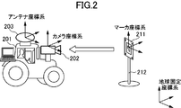
- a visual marker as indicated by reference numeral 211 in FIG.
- the visual marker 211 is fixed to the support base 212 as necessary. Then, the position and orientation of the installed visual marker 211 are accurately measured in advance.
- the “position” of the visual marker indicates a position on the earth fixed coordinate system.
- the “posture” of the visual marker is defined as the posture of a coordinate system (hereinafter referred to as “marker coordinate system” if necessary) fixed to the visual marker with respect to the fixed earth coordinate system.
- the position and orientation of the visual marker 211 measured in advance are stored in association with the ID number of the visual marker 211 in a storage device related to the arithmetic device mounted on the moving body 201 shown in FIG.
- the moving body 201 further includes a camera 202 as a marker detection unit and a GNSS antenna 203 as a part of a satellite positioning unit that receives a signal from a positioning satellite.
- the relative positional relationship between the camera 202 and the GNSS antenna 203 is measured in advance.
- the moving body 201 is moved so that the visual marker 211 enters the field of view of the camera 202, and the visual marker 211 is photographed by the camera 202. To do.
- the visual marker 211 will be described.
- the visual marker 211 used in the present embodiment includes a lens array including a large number of lenses arranged on a two-dimensional plane on a dot pattern arranged at a predetermined interval on the two-dimensional plane. The distance between the dots in the dot pattern is slightly different from the distance between the lenses in the lens array.
- a visual marker is described in Japanese Patent No. 5842248, and the specific structure of such a visual marker is shown in FIGS.
- the visual marker having the structure shown in FIG. 37 of the above patent publication is generally planar, but the position of the shading pattern changes sensitively to changes in the angle between the direction of the line of sight and the normal of the visual marker. To do. For this reason, depth information can be virtually added to a planar visual marker. When this planar visual marker is used, a change in angle can be detected with high accuracy, particularly near the front of the visual marker. The relationship between the angle between the direction of the line of sight and the normal of the visual marker and the position of the shading pattern is measured and stored in advance.
- the visual marker is photographed by the camera 202 mounted on the moving body 201, and the image is input to an arithmetic unit mounted on the moving body.
- the position and orientation of the visual marker 211 relative to the camera 202 can be calculated by the program. From this result, the position and orientation data of the visual marker 211 that has been measured and stored in advance in advance, and the relative positional relationship between the camera 202 and the GNSS antenna 203, the position of the GNSS antenna 203 in the fixed earth coordinate system. And the posture can be obtained.
- the information on the accurate position and orientation of the GNSS antenna 203 obtained in this way is used for estimating the positioning parameter of the PPP method. As described above, it takes about several tens of minutes to about one hour for the PPP-type arithmetic unit to be able to estimate the position with high accuracy after being activated. This is the initial position of the GNSS antenna 203. This is because, when the estimation accuracy is not high, it is necessary to observe a large amount of satellite signals in order to obtain an estimated value with sufficient accuracy when estimating the positioning parameters including the position.
- the satellite signal necessary for obtaining the same positioning parameter estimation accuracy can be obtained. It has been confirmed that the amount of observation can be dramatically reduced, and as a result, the time required for highly accurate position estimation can be reduced to, for example, several minutes.
- the visual marker 211 is installed on a support base 212 provided near the entrance of the farm, and the position and By accurately measuring the posture in advance, the work machine is started, and the visual marker 211 is photographed by the camera 202, so that the precise position of the GNSS antenna 203 can be obtained with high accuracy within a few minutes after the start of the work machine. Can be estimated. Therefore, the time from the start of the work machine to the start of work can be greatly shortened.
- a flat visual marker As another example of the visual marker, for example, a three-point marker often used in space applications can be used.
- the three-point marker has a rod-like member extending in the normal direction in order to obtain depth information.
- the posture of the three-point marker can be estimated from the visual shift of the front and rear ends of the rod-shaped member and the length of the rod-shaped member.
- a space station or the like is provided with a plurality of three-point markers in order to obtain the attitude of the space station from the outside. In a situation where the installation location is not strictly required, such a three-point marker can be used as a visual marker.
- the PPP method is used as the satellite positioning method using GNSS.
- this embodiment is not limited to the PPP method as long as it is a satellite positioning method that does not require a reference station and requires time for initialization processing. This is the same in the following embodiments.
- Embodiment 2 In the first embodiment, it is assumed that the position and orientation of the visual marker 211 are accurately measured in advance. Various methods are conceivable for the measurement of the position and orientation of the visual marker 211, including a method using a surveying instrument.
- the moving body 201 that can estimate the position with high accuracy is used. Then, the position and posture of the visual marker 211 are accurately measured. As already described, in the PPP method, it takes a certain amount of time before the position of the moving body 201 can be accurately estimated. However, if the position can be estimated with high accuracy even if it takes a long time, The precise position and orientation of the visual marker 211 can be measured using the camera 202 mounted on the moving body 201 as follows.
- FIG. 3 to 9 are diagrams showing a method for measuring the position and posture of the visual marker 211.
- FIG. 3 As shown in FIG. 3, the visual marker 211 is on the right side, and the moving body 201 equipped with the camera 202 and the GNSS antenna 203 is on the left side.
- the distance between the moving body 201 and the visual marker 211 is about 10 meters.
- the position of the GNSS antenna 203 has already been estimated with high accuracy by the PPP method.
- an inertial measurement device IMU: Inertial Measurement Unit
- IMU Inertial Measurement Unit
- the posture of the moving body 201 is necessary for calculating the position of the GNSS antenna 203 with respect to the camera 202.
- virtual markers A and B are set at two points symmetrical with respect to the straight line and separated from the straight line to some extent on the vertical bisector of the straight line connecting the distal point and the proximal point of the moving body 201, respectively.
- the position of each virtual marker in the coordinate system is stored.
- the moving body 201 starts moving from the distal point toward the proximal point.
- the visual marker 211 is observed by the camera 202, and the relative position and orientation of the visual marker 211 with respect to the camera 202 are measured.
- the positions of the virtual markers A and B in the marker coordinate system stored first, and the relative position of the visual marker 211 with respect to the camera 202 measured at the observation point From the posture, the positions of the virtual markers A and B with respect to the camera 202 are obtained, and the distances from the camera 202 to the virtual markers A and B are calculated based on the positions.
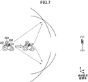
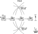
- FIG. 6 a circle having a radius as a distance to each of the virtual markers A and B obtained in FIG. 5 around the camera position (measured by satellite positioning and IMU) in the fixed earth coordinate system, Two circles are obtained for each observation point corresponding to each of the virtual markers A and B. As shown in FIG. 7, such an observation operation is performed at a number of observation points (for example, 100 points) while the moving body 201 moves from the distal point to the proximal point. Then, as shown in FIG. 8, for each of the virtual markers A and B, a number of circles equal to the number of observation points is obtained, and the intersections of these circles (stars in FIG. 8) are the respective points in the earth fixed coordinate system. This is the estimated position of the virtual marker.
- a number of observation points for example, 100 points
- FIG. 8 for each of the virtual markers A and B, a number of circles equal to the number of observation points is obtained, and the intersections of these circles (stars in FIG. 8) are the respective points in the earth fixed coordinate system.
- the description is based on the geometrical interpretation that the intersection of the circles is the estimated position of the virtual marker, but in the actual calculation, from each observation point described with reference to FIG. 5 to each virtual marker.
- the estimated position of the virtual marker is calculated using an optimization method based on the residual of the distance between the distance and the distance obtained from the position of each observation point and the estimated position of the virtual marker.
- the estimated positions (stars in FIG. 9) of the virtual markers A and B in the fixed earth coordinate system thus obtained and the marker coordinates of the preset virtual markers A and B described in relation to FIG. From the position in the system, as shown in FIG. 9, the position and orientation of the visual marker 211 in the fixed earth coordinate system (the position and orientation of the marker coordinate system with respect to the fixed earth coordinate system) are calculated.
- the setting position of the virtual marker can be variously set in addition to the vertical bisector of the straight line connecting the distal point and the proximal point as described above.
- the traveling path of the moving body that moves while observing the visual marker is not limited to the straight line connecting the distal point and the proximal point as described above.
- FIG. 10 to 16 are diagrams showing a method for measuring the position and orientation of the visual marker 211.
- FIG. 10 the visual marker 211 is in front of the moving body 201 on which the camera 202 and the GNSS antenna 203 are mounted.
- the distance between the moving body 201 and the visual marker 211 is about 10 meters.
- the position of the GNSS antenna 203 has already been estimated with high accuracy by the PPP method.
- the exact position and orientation of the visual marker 211 in the fixed earth coordinate system are unknown, but a temporary value is set for each in order to use for the calculation shown below. The temporary value does not need to be set as close as possible to the true value.
- an error from the true value may be about 10 m in position or about 10 degrees in posture.
- the moving body 201 starts moving in a direction approaching the visual marker 211.
- the visual marker 211 is observed by the camera 202, and the relative position and orientation of the visual marker 211 with respect to the camera 202 are measured.
- the relative position and orientation of the visual marker 211 with respect to the camera 202 measured at the observation point, and the position of the temporarily set visual marker 211 in the earth fixed coordinate system and From the attitude, the estimated position of the GNSS antenna 203 in the fixed earth coordinate system is calculated.
- the measurement position of the GNSS antenna 203 in the fixed earth coordinate system is measured by satellite positioning.
- the time when the camera 202 captures the visual marker 211 and the time when the position of the GNSS antenna 203 is measured by satellite positioning need to be synchronized.
- the synchronization between the shooting time and the measurement time is, for example, by inputting a pulse signal output from the GNSS receiver in synchronization with the GPS time to a camera having an external trigger input function and synchronizing the GPS time with the camera. This can be achieved by releasing the shutter.
- the position of the GNSS antenna 203 in the earth fixed coordinate system obtained by using the camera 202 and the visual marker 211 for one observation point during the movement of the moving body 201 (“+ (plus sign) in FIG. 13)”.
- the position measurement result of the GNSS antenna 203 obtained by using satellite positioning in the fixed earth coordinate system (indicated by “ ⁇ (white circle)” in FIG. 13). be able to.
- such an observation operation is performed at a large number of observation points (for example, 100 points) while the moving body 201 moves from the distal point to the proximal point with respect to the visual marker 211.
- the position measurement result in the fixed earth coordinate system of the set of GNSS antennas 203 equal to the number of observation points is obtained.
- the position in the earth fixed coordinate system at each observation point of the GNSS antenna 203 obtained by using the camera 202 and the visual marker 211 indicated by + in FIG. It changes in accordance with the position and orientation values of the previously set visual marker 211 in the earth fixed coordinate system.
- the difference between the center of the position indicated by the + mark and the center of the position measured by the satellite positioning indicated by the ⁇ mark is as small as possible for all observation points.
- the position and orientation values of the visual marker 211 in the earth fixed coordinate system are obtained. This makes it possible to estimate the position and orientation of the visual marker 211 in the fixed earth coordinate system that most closely matches the satellite positioning result at each observation point.
- the precise measurement result of the position and orientation of the visual marker 211 thus obtained can be used as information on the position and orientation of the visual marker in the first embodiment.
- the PPP method is used. It is possible to greatly reduce the time required for highly accurate position estimation at.
- the positioning parameters are estimated by a method similar to the method described in the first embodiment (hereinafter referred to as “method 1”).
- method 1 the method described in the first embodiment
- the visual marker 211 does not know whether or not its position and posture are the exact position and posture that should originally be.
- method 2 the position of the visual marker 211 in the fixed earth coordinate system is estimated by the method shown in the second embodiment (hereinafter referred to as “method 2”) using the estimated positioning parameter.
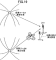
- FIG. 19 schematically shows this.
- the positioning error is obtained from the difference between the position P and the position Q, and the initial position is corrected using this as a correction amount as shown in FIG. 20, and the positioning parameter is estimated again by the method 1, the positioning error is remarkably reduced. can do. Furthermore, if the position and orientation of the visual marker are estimated by the method 2 in a state where the positioning error is reduced, the installation position and orientation of the visual marker described in the fifth embodiment will be described even when sufficient time has not elapsed since the start of positioning. Can be evaluated.
- the position and orientation of the visual marker 211 are required to be accurate and accurate.
- the position and orientation of the visual marker 211 change due to an earthquake or the like, and the position and direction of the ground change. It is possible that posture changes.
- the accurate position and orientation of the GNSS antenna 203 cannot be estimated with high accuracy within a few minutes after the start-up of the work machine described in the first embodiment. Therefore, in the fifth embodiment, the accuracy of the position and orientation of the visual marker 211 whose position and orientation has already been measured is evaluated.
- the accuracy of position estimation of the GNSS antenna 203 is about several centimeters if the estimation operation is continued for a certain time or more. For example, it is considered that this degree of estimation accuracy is obtained when the moving body 201 finishes the work of the day.
- the visual marker 211 is photographed, and as described in the first embodiment, the image is input to the camera 202 by the program on the arithmetic unit mounted on the moving body as an input.
- the position and orientation of the visual marker 211 is calculated, and the position and orientation data of the visual marker 211 that has been precisely measured and stored in advance and the relative positional relationship between the camera 202 and the GNSS antenna 203 are used to determine fixed coordinates on the earth.
- the position and orientation of the GNSS antenna 203 in the system are obtained.
- the position and orientation of the visual marker 211 can be corrected, or here
- the position and orientation of the visual marker 211 obtained in the above can be newly stored in the storage device and used at the start of the next work.
- two cylinders having a known radius are used as markers, and these are placed vertically by separating them to some extent (for example, 5 m apart), and the center position of the cylinder in the fixed earth coordinate system is measured in advance. Keep it.
- the moving body is equipped with a laser scanner and an IMU as a marker detection unit.
- the laser scanner emits a laser beam, and scans the laser beam radially from a laser rangefinder that can measure the distance from the time it takes to reflect the target object and return to the target object with high accuracy. Use what you can.
- the position of the laser scanner in the fixed earth coordinate system can be calculated from the position of the laser scanner in the fixed earth coordinate system and the azimuth obtained by the IMU. It is possible to calculate, and using this, satellite positioning processing can be executed as in the first embodiment.
- FIG. 21 shows the detection principle.
- the left side of FIG. 21 shows a case where there is no error in the marker installation posture, that is, a case where the marker installation posture measured in advance and held by the system matches the actual marker installation posture.
- the ⁇ mark connected by the line in the upper frame is the estimated position of the moving body obtained by observing the marker, and the ⁇ mark connected by the line in the lower frame was obtained by satellite positioning This is the estimated position of the moving object.
- the right side of FIG. 21 shows a case where there is an error in the marker installation posture.
- the estimated position of the moving object obtained by observing the marker at the first observation point is due to the effect of the marker installation posture error, as long as there is no error in the installation posture, as indicated by the ⁇ mark at the left end in the upper frame. Compare (offset).
- offset When satellite positioning is initialized using this estimated position information, an error corresponding to the previous offset remains in the satellite positioning result after the initialization is completed. Although this error gradually decreases with the passage of time, it may be considered constant within the time range considered here.
- the estimated position where the marker is installed is obtained by the same fitting as described above using these measurement results, it does not coincide with the installation position measured in advance and held by the system, and a difference occurs. This is because the error amount of the estimated position of the moving object obtained by the marker observation changes according to the distance from the marker, whereas the error amount of the estimated position of the moving object obtained by the satellite positioning is almost constant. to cause.
- the marker observation result and the marker installation position / posture estimation result can be shared among a plurality of moving bodies using communication.
- a moving body B has been described in the third embodiment by sharing information on the marker installation position and posture estimated by the method described in the third embodiment with another moving body B. Even if the estimation by the method is not performed by itself, the accurate information on the installation position and orientation of the marker can be used.
- information on the position and orientation of the marker is shared with the ID assigned to the marker by means such as a two-dimensional code. Based on the ID and the rough position information of the moving body, it is possible to uniquely determine where the marker is installed.
- FIG. 22 shows the contents of some embodiments described so far, and in each embodiment, what is known information and what is an estimation target.
- (A), (B), and (C) correspond to each other, and (A), (B), and (C) correspond to the above-described Embodiment 1, Embodiment 3, and Embodiment 2, respectively.
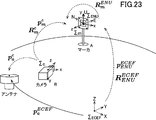
- FIG. 23 shows a coordinate system used in the following description
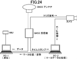
- FIG. 24 shows a configuration of a system manufactured for an experiment
- FIG. 25 shows a method of an experiment performed by mounting the manufactured system on a moving body. ing. The meaning of each symbol shown in FIG. 23 is shown in FIG.
- FIG. 22A the initialization experiment shown in FIG. 22A will be described.
- a marker was placed beside the road, and the position and orientation relative to the fixed earth coordinate system were accurately measured in advance.
- the following is an example of a position and orientation measurement method.
- point A the position in the fixed earth coordinate system of the point where the marker is installed
- point B the point 10 meters away from the marker
- a marker is set at point A so that the y-axis of the marker coordinate system matches the vertical direction, and a camera is set at point B so that the optical center is directly above point B. did. And the marker was image
- the optical axis of the camera is parallel to the line segment connecting the points A and B.
- the posture of the marker with respect to the camera By measuring the posture of the marker with respect to the camera, the posture of the marker with respect to the line segment connecting point A and point B can be obtained.
- the attitude of the marker in the earth fixed coordinate system is calculated from this and the positions of the points A and B measured previously in the earth fixed coordinate system. Further, the height from the point A to the center of the marker is measured.
- the position of the marker in the fixed earth coordinate system is calculated from this and the previously measured position of the point A in the fixed earth coordinate system.
- a base station for post-processing RTK was set up on the side of the road for reference and collected positioning data.
- the moving body was moved forward from the front of the marker toward the marker, and the moving body was stopped at a point about 10 m away from the marker where the marker entered the field of view of the camera. Note that the location of this point is unknown.
- satellite positioning by PPP was started, and at the same time, marker measurement was started and the calendar (orbit / time information) of the satellite was acquired.
- the satellite calendar can usually be obtained within 30 seconds.
- the following formula is used using the marker measurement results: The positioning calculation is started with the position of the GNSS antenna calculated by the above as an initial value. Refer to FIG. 23 and FIG. 27 for the meaning of each symbol in this equation.
- positioning data was acquired while advancing the moving body to a point about 20 m away from the starting point after 60 seconds had elapsed from the start of positioning.
- the data thus obtained was compared and evaluated using post-processing RTK as a reference.
- FIG. 26 is a diagram showing the result of this comparison.
- the left side of FIG. 26 is a case where initialization using a marker is not performed. It can be seen that the error does not sufficiently converge at 60 seconds, and an error exceeding 1 m appears.
- initialization is performed using the marker shown on the right side of FIG. 26, it can be seen that convergence is achieved instantaneously and accuracy within 3 cm of horizontal error is achieved.
- Table 1 shows the horizontal positioning accuracy in each trial in five trial experiments. As can be seen from Table 1, very high accuracy was obtained.
- a measurement experiment of the marker installation position and orientation shown in FIG. Similar to the experiment of (A) above, the moving body is advanced to the start point, satellite positioning and marker measurement by PPP are started, and initialization is performed. Unlike the case of the initialization in (A), the moving body starts moving forward while continuing the marker measurement. While making sure that the marker does not deviate from the field of view of the camera, it moves forward to a point about 1 m before the marker. Thereby, the marker measurement data synchronized with the positioning data and the positioning data can be acquired during movement.
- the marker position and orientation are estimated based on the acquired data and Equation 1 by the above-described marker installation position and orientation estimation method, and a horizontal position error of 7.2 mm and an azimuth angle error of 0.081 degrees are obtained. It was.
- the estimation of positioning parameters is usually performed by sequential processing (filter).
- a filter extended Kalman filter
- initialization is performed by inputting an estimated value of the position of the GNSS antenna obtained by marker observation as an initial value of the filter.
- the positioning parameter can be estimated by a method other than the filter.
- a specific example of such an estimation method is given below. In the following, as shown in the second embodiment, it is assumed that the satellite positioning and the marker observation are executed in synchronization while the moving body is moving, and both observation data can be obtained.
- the first example is when a filter is used.
- estimation accuracy can be improved by incorporating information such as the relative position / velocity and relative attitude / angular velocity of the moving body obtained by the marker observation into the dynamics of the system.
- the second example is based on batch processing.
- the satellite positioning data and marker observation data for a certain period can be handled collectively, and the parameters can be estimated by a technique such as nonlinear least squares.
- the third example is a hybrid technique.
- it is a technique having both filter and batch processing aspects. This corresponds to a technique called smoothing “and mapping” in the field of robotics. It is possible to improve the accuracy and reduce the calculation load by performing estimation in batches using data of a certain period and sliding the target period over time.
- Error detection calculation is performed. This is because the positioning data and the observation data of the marker are acquired in synchronization, and calculation by post-processing is possible. It can be expected that the difference in the estimated amount of the marker position thus obtained is smaller than the value obtained for the first time. By repeating such a process, it is possible to finally suppress an error in the marker installation posture within an allowable range required for estimation of the antenna position.
Landscapes
- Engineering & Computer Science (AREA)
- Radar, Positioning & Navigation (AREA)
- Remote Sensing (AREA)
- Physics & Mathematics (AREA)
- General Physics & Mathematics (AREA)
- Computer Networks & Wireless Communication (AREA)
- Position Fixing By Use Of Radio Waves (AREA)
Abstract
衛星測位における初期化処理にかかる時間を短縮する。予め測定された視覚マーカ211の地球固定座標系における位置及び姿勢は、移動体201に搭載された演算装置に関連する記憶装置に視覚マーカ211のID番号と対応付けて記憶させておく。移動体201には撮影装置としてのカメラ202及び測位衛星から信号を受信するGNSSアンテナ203が搭載されている。視覚マーカ211の正確な位置及び姿勢を予め精密に測定しておくことによって、カメラ202で撮影しその画像を入力として移動体に搭載した演算装置上のプログラムによってカメラ202に対する視覚マーカ211の位置及び姿勢を算出することができる。この結果から地球固定座標系におけるGNSSアンテナ203の位置を求めることができ、こうして求めたGNSSアンテナ203の正確な位置の情報を、PPP方式の測位パラメータの推定に利用する。
Description
本発明は、GNSS(Global Navigation Satellite System)を用いた測位、その中でも単独搬送波位相測位(PPP)方式による衛星測位システム及び衛星測位方法に関する。
GNSSを用いた測位には幾つかの方式が存在し、その中にRTK(Real-Time Kinematic)と呼ばれる方式がある。RTK方式では、数センチメートル程度の精度でリアルタイムに移動体の測位が可能である。その一方で、RTK方式では、このような利点を実現するために、移動体の他に基準局を設けることが必要となり、移動体はこの基準局との間でも信号をやりとりしなければならない。
GNSSを用いた測位の別の方式として、単独搬送波位相測位(PPP:Precise Point Positioning)方式、およびPPP方式において搬送波位相バイアスの整数解を求めることで精度向上を図るPPP-AR(PPP Ambiguity Resolution)方式が知られている(本明細書では、両者を比較対照する場合を除いて、PPP方式及びPPP-AR方式を含めて、PPP方式という)。PPP方式は、RTK方式とは異なり、基準局が不要でありながら、RTK方式と同程度の精度が実現できるという利点がある。その一方で、PPP方式では、衛星軌道や衛星時計の誤差、および電離層や対流圏を通過することによる信号の遅延量や搬送波位相バイアスなど多数のパラメータを推定する初期化処理が必要となる。それによって、測位開始からパラメータの推定値が収束して実用的な測位精度が達成されるまでに数十分から1時間程度の時間がかかる。このため、例えば測量、土木作業、建設作業、農作業等にPPP方式を利用しようとする場合は、この初期化処理が終わるまでは作業を開始できないことが欠点とされていた。(非特許文献1~3参照)
三吉他「複数GNSS対応単独搬送波位相測位(PPP)技術の研究開発と評価結果」第59回宇宙科学技術連合講演会講演集2H12,2015
高須他「MADOCAにおけるPPP-AR機能の拡張と評価」第59回宇宙科学技術連合講演会講演集2H13,2015
谷山他「PPP初期収束時間短縮のための補強情報の生成と評価」第59回宇宙科学技術連合講演会講演集2H14,2015
本発明はこのような事情に基づいてなされたものであり、地球上に設置されたマーカを利用して衛星測位における初期化処理にかかる時間を短縮することができるシステム及び方法、並びに、マーカの位置及び/又は姿勢を正確に測定し又は評価することができる方法を提供することを目的とする。また、マーカの姿勢誤差を判定するシステム又は方法も提供する。
本発明に係る衛星測位システムは、
衛星測位部、マーカ検出部、及び演算部を有する移動体と、
予め地球固定座標系における位置及び姿勢が測定されているマーカと、を備え、
前記演算部は、前記マーカ検出部によって検出された前記マーカの位置及び姿勢に基づいて前記移動体の地球固定座標系における位置を算出し、
前記衛星測位部は、前記演算部が算出した前記移動体の位置に関する情報を受け取って、衛星測位処理を実行する。
衛星測位部、マーカ検出部、及び演算部を有する移動体と、
予め地球固定座標系における位置及び姿勢が測定されているマーカと、を備え、
前記演算部は、前記マーカ検出部によって検出された前記マーカの位置及び姿勢に基づいて前記移動体の地球固定座標系における位置を算出し、
前記衛星測位部は、前記演算部が算出した前記移動体の位置に関する情報を受け取って、衛星測位処理を実行する。
前記マーカ検出部は、前記マーカの画像を撮影する撮影装置を含むことができる。
また、本発明に係る衛星測位システムは、
衛星測位部、マーカ検出部、及び演算部を有する移動体と、
予め地球固定座標系における位置が測定されている複数のマーカと、を備え、
前記演算部は、前記マーカ検出部によって検出された前記複数のマーカの位置に基づいて前記移動体の地球固定座標系における位置を算出し、
前記衛星測位部は、前記演算部が算出した前記移動体の位置に関する情報を受け取って、衛星測位処理を実行する。
衛星測位部、マーカ検出部、及び演算部を有する移動体と、
予め地球固定座標系における位置が測定されている複数のマーカと、を備え、
前記演算部は、前記マーカ検出部によって検出された前記複数のマーカの位置に基づいて前記移動体の地球固定座標系における位置を算出し、
前記衛星測位部は、前記演算部が算出した前記移動体の位置に関する情報を受け取って、衛星測位処理を実行する。
本発明に係る衛星測位方法は、
地球固定座標系におけるマーカの位置、又は前記マーカの姿勢を予め測定するステップと、
移動体に搭載されたマーカ検出部により前記マーカを検出し、それに基づいて移動体の地球固定座標系における位置を算出するステップと、
前記移動体の地球固定座標系における位置に関する情報を移動体に搭載された衛星測位部に供給し、衛星測位処理を実行するステップと、
を備える。
地球固定座標系におけるマーカの位置、又は前記マーカの姿勢を予め測定するステップと、
移動体に搭載されたマーカ検出部により前記マーカを検出し、それに基づいて移動体の地球固定座標系における位置を算出するステップと、
前記移動体の地球固定座標系における位置に関する情報を移動体に搭載された衛星測位部に供給し、衛星測位処理を実行するステップと、
を備える。
本発明に係るマーカの位置及び姿勢を測定する方法は、
衛星測位部、マーカ検出部、及び演算部を有する移動体によって、地上に固定されたマーカの位置及び姿勢を測定する方法であって、
前記移動体の地球固定座標系における位置を取得するステップと、
前記移動体を任意の経路で移動させるステップと、
前記移動体の移動中に、複数の地点のそれぞれにおいて、前記マーカ検出部により前記マーカを観測して前記マーカの前記マーカ検出部に対する相対位置及び相対姿勢を計測し、その計測結果に基づいて各観測地点における前記移動体の前記マーカに対する相対位置を算出するステップと、
前記各観測地点での、前記移動体の地球固定座標系における位置と、前記移動体の前記マーカに対する算出された相対位置を用いて、前記マーカの地球固定座標系における位置及び姿勢を推定するステップと、
を備える。
衛星測位部、マーカ検出部、及び演算部を有する移動体によって、地上に固定されたマーカの位置及び姿勢を測定する方法であって、
前記移動体の地球固定座標系における位置を取得するステップと、
前記移動体を任意の経路で移動させるステップと、
前記移動体の移動中に、複数の地点のそれぞれにおいて、前記マーカ検出部により前記マーカを観測して前記マーカの前記マーカ検出部に対する相対位置及び相対姿勢を計測し、その計測結果に基づいて各観測地点における前記移動体の前記マーカに対する相対位置を算出するステップと、
前記各観測地点での、前記移動体の地球固定座標系における位置と、前記移動体の前記マーカに対する算出された相対位置を用いて、前記マーカの地球固定座標系における位置及び姿勢を推定するステップと、
を備える。
ここで、前記各観測地点での、前記移動体の地球固定座標系における位置と、前記移動体の前記マーカに対する算出された相対位置との間の距離を算出し、前記各観測地点の全てにおける前記距離の総和に基づく評価関数を最小とするような前記マーカの地球固定座標系における位置及び姿勢を推定値とすることができる。
さらに、本発明に係るマーカの位置及び姿勢を測定する方法は、
衛星測位部、マーカ検出部、及び演算部を有する移動体によって、地上に固定されたマーカの位置及び姿勢を測定する方法であって、
前記移動体の地球固定座標系における位置を取得するステップと、
前記マーカに対する任意の位置に複数の仮想マーカを設定するステップと、
前記移動体を任意の経路で移動させるステップと、
前記移動体の移動中に、複数の地点のそれぞれにおいて、前記マーカ検出部により前記マーカを観測して前記マーカの位置及び姿勢を計測し、その結果に基づいてそれぞれの地点において前記複数の仮想マーカの移動体に対する相対位置を算出し、各観測地点において算出された前記複数の仮想マーカの算出相対位置から前記複数の仮想マーカの地球固定座標系における位置を推定するステップと、
前記複数の仮想マーカの推定された位置から、前記マーカの位置及び姿勢を推定するステップと、
を備える。
衛星測位部、マーカ検出部、及び演算部を有する移動体によって、地上に固定されたマーカの位置及び姿勢を測定する方法であって、
前記移動体の地球固定座標系における位置を取得するステップと、
前記マーカに対する任意の位置に複数の仮想マーカを設定するステップと、
前記移動体を任意の経路で移動させるステップと、
前記移動体の移動中に、複数の地点のそれぞれにおいて、前記マーカ検出部により前記マーカを観測して前記マーカの位置及び姿勢を計測し、その結果に基づいてそれぞれの地点において前記複数の仮想マーカの移動体に対する相対位置を算出し、各観測地点において算出された前記複数の仮想マーカの算出相対位置から前記複数の仮想マーカの地球固定座標系における位置を推定するステップと、
前記複数の仮想マーカの推定された位置から、前記マーカの位置及び姿勢を推定するステップと、
を備える。
ここで、前記任意の経路は、前記マーカからみた遠位点と近位点とを結ぶ直線であり、前記複数の仮想マーカは、前記マーカとそれぞれの前記仮想マーカを結ぶ直線上で前記移動体から前記直線に下ろした垂線と前記直線との交点に位置するものとすることができる。
また、本発明に係るマーカの位置及び姿勢を評価する方法は、
衛星測位部、マーカ検出部、及び演算部を有する移動体によって、地上に固定されたマーカの位置及び姿勢を評価する方法であって、
地上に固定されたマーカの位置及び姿勢を、記憶部に予め記憶しておくステップと、
前記記憶部に予め記憶された前記マーカの位置及び姿勢と、請求項6又は7に記載の方法により測定された前記マーカの位置及び姿勢とを比較するステップと、
を備える。
衛星測位部、マーカ検出部、及び演算部を有する移動体によって、地上に固定されたマーカの位置及び姿勢を評価する方法であって、
地上に固定されたマーカの位置及び姿勢を、記憶部に予め記憶しておくステップと、
前記記憶部に予め記憶された前記マーカの位置及び姿勢と、請求項6又は7に記載の方法により測定された前記マーカの位置及び姿勢とを比較するステップと、
を備える。
本発明に係る衛星測位システムは、
衛星測位部、マーカ検出部、及び演算部を有する移動体と、
予め地球固定座標系における位置及び姿勢が測定されているマーカと、を備え、
前記演算部は、前記マーカ検出部によって検出された前記マーカから前記移動体の位置を推定し、
前記衛星測位部は前記移動体の当該推定位置に関する情報を受け取って初期化を行い、前記演算部は、
当該初期化後に前記マーカ検出部が前記マーカを観測することによって前記マーカの位置を推定し、そのマーカの推定位置と予め前記移動体が保持している前記マーカの位置に関する情報を比較することによって、あらかじめ前記移動体が保持している前記マーカの姿勢に誤差があるか否かを判定する。
衛星測位部、マーカ検出部、及び演算部を有する移動体と、
予め地球固定座標系における位置及び姿勢が測定されているマーカと、を備え、
前記演算部は、前記マーカ検出部によって検出された前記マーカから前記移動体の位置を推定し、
前記衛星測位部は前記移動体の当該推定位置に関する情報を受け取って初期化を行い、前記演算部は、
当該初期化後に前記マーカ検出部が前記マーカを観測することによって前記マーカの位置を推定し、そのマーカの推定位置と予め前記移動体が保持している前記マーカの位置に関する情報を比較することによって、あらかじめ前記移動体が保持している前記マーカの姿勢に誤差があるか否かを判定する。
本発明に係るマーカの姿勢誤差を判定する方法は、
衛星測位部、マーカ検出部、及び演算部を有する移動体によって、あらかじめ移動体が保持しているマーカの姿勢誤差を判定する方法であって、
予めマーカの位置及び姿勢を測定し、その結果を前記移動体の演算部が保持するステップと、
前記マーカ検出部が前記マーカを観測し、その結果から前記演算部が前記移動体の位置を推定するステップと、
前記衛星測位部が、前記移動体の当該推定位置に関する情報を受け取って初期化を行うステップと、
前記初期化の後に前記マーカ検出部が前記マーカを観測し、その結果に基づいて前記マーカの位置を推定するステップと、
前記演算部が、前記推定された前記マーカの位置を前記演算部が保持するマーカの位置と比較して、その比較結果に基づいてマーカの姿勢に誤差があるか否かを判定するステップと、
を備える。
衛星測位部、マーカ検出部、及び演算部を有する移動体によって、あらかじめ移動体が保持しているマーカの姿勢誤差を判定する方法であって、
予めマーカの位置及び姿勢を測定し、その結果を前記移動体の演算部が保持するステップと、
前記マーカ検出部が前記マーカを観測し、その結果から前記演算部が前記移動体の位置を推定するステップと、
前記衛星測位部が、前記移動体の当該推定位置に関する情報を受け取って初期化を行うステップと、
前記初期化の後に前記マーカ検出部が前記マーカを観測し、その結果に基づいて前記マーカの位置を推定するステップと、
前記演算部が、前記推定された前記マーカの位置を前記演算部が保持するマーカの位置と比較して、その比較結果に基づいてマーカの姿勢に誤差があるか否かを判定するステップと、
を備える。
前記衛星測位部は、単独搬送波位相測位(PPP)方式による衛星測位処理を実行するものとすることができる。
測定及び/又は評価された前記マーカの地球固定座標系における位置及び姿勢の情報を、前記移動体と、前記移動体と異なる移動体との間で共有することができる。
予め地球固定座標系における位置及び姿勢が測定されているマーカの位置及び姿勢、あるいは、予め地球固定座標系における位置が測定されている複数のマーカの位置を検出し、これに基づいて移動体の地球固定座標系における位置を算出し、その情報を用いて衛星測位処理を実行することにより、衛星測位における初期化処理にかかる時間を従来と比較して大幅に短縮することができる。
また、前述の、地上に固定されたマーカの位置及び姿勢を測定する方法を実行することによっても、衛星測位における初期化処理にかかる時間を短縮することができる。
さらに、地上に固定されたマーカの位置及び/又は姿勢を予め記憶しておき、前述の方法でマーカの位置及び/又は姿勢を測定し、両者を比較することによって、マーカの現在の位置及び/又は姿勢の正確さを評価することができる。
以下に、本発明の実施形態について説明する。なお、本発明は、以下の実施形態によって限定的に解釈されるものではない。
なお、本明細書で言う「初期化」には、測位中断後の再初期化も含むものとする。すなわち、GNSSアンテナと衛星との間に障害物が存在することなどにより衛星からの信号が受信できなくなった場合、その後に再び受信できるようになったとしても、測位を再開するためには中断時間に応じて初期化と同様の処理(再初期化)が必要になる場合があり、このような測位中断後の再初期化も含むものとする。
なお、本明細書で言う「初期化」には、測位中断後の再初期化も含むものとする。すなわち、GNSSアンテナと衛星との間に障害物が存在することなどにより衛星からの信号が受信できなくなった場合、その後に再び受信できるようになったとしても、測位を再開するためには中断時間に応じて初期化と同様の処理(再初期化)が必要になる場合があり、このような測位中断後の再初期化も含むものとする。
図1は、RTK方式とPPP方式について、誤差の主な原因と、これらの誤差を低減するための処理の方法を比較対照した図である。図1には、測位衛星からの信号を受信する移動体として、建設現場で使用される車両が示されており、この車両に測位衛星からの信号を受信するGNSSアンテナが搭載されている。この他に、農業で使用される農業機械、測量現場で使用される測量機器、建設現場などで使用される建設機器などの移動体にも、測位衛星からの信号を受信するGNSSアンテナを搭載して、衛星測位を実行することができる。
図1に示すように、衛星には高精度の時計が搭載されているが、その時計にも誤差が生じ、また衛星の軌道にも誤差が生じる。そして、測位衛星から発せられる信号は、移動体のGNSSアンテナに到達するまでに電離層及び対流圏を伝搬するが、その際に遅延を受け、この遅延による誤差も生じる。RTK方式ではこのような誤差に対して、精密な位置が分かっている基準局を設置し、移動体と基準局の両方で少なくとも5つの測位衛星からの電波を受け、さらに移動体と基準局との間で信号のやりとりをすることで、このような誤差をキャンセルし、数センチメートル程度の精度を達成することができる。
一方、PPP方式では、4つ以上の測位衛星から電波を受け、観測結果及びモデルを用い、衛星軌道や衛星時計の誤差、および電離層や対流圏を通過することによる信号の遅延量や搬送波位相バイアスなど多数のパラメータを推定する初期化処理を行う。初期化処理は、衛星測位を行おうとする移動体に搭載された演算装置によって行うことができる。かかる初期化処理が済めば、地球に固定された座標系(地球固定座標系という)の上での位置について、RTKと同程度の精度で推定することができる。このようにPPP方式では基準局及び基準局と移動体との間の通信手段は不要となるものの、初期化処理に数十分から1時間程度の時間がかかる。
(実施形態1)
本実施形態では、PPP方式における初期化処理にかかる時間を短縮するために、図2に符号211で示すような視覚マーカを設置する。視覚マーカ211は、必要に応じて支持台212に固定する。そして、設置した視覚マーカ211の位置及び姿勢を予め精密に測定しておく。ここで、視覚マーカの「位置」は、地球固定座標系の上での位置を指す。また、視覚マーカの「姿勢」は、地球固定座標系に対する視覚マーカに固定された座標系(以下必要に応じて「マーカ座標系」という)の姿勢として定義する。
本実施形態では、PPP方式における初期化処理にかかる時間を短縮するために、図2に符号211で示すような視覚マーカを設置する。視覚マーカ211は、必要に応じて支持台212に固定する。そして、設置した視覚マーカ211の位置及び姿勢を予め精密に測定しておく。ここで、視覚マーカの「位置」は、地球固定座標系の上での位置を指す。また、視覚マーカの「姿勢」は、地球固定座標系に対する視覚マーカに固定された座標系(以下必要に応じて「マーカ座標系」という)の姿勢として定義する。
予め測定された視覚マーカ211の位置及び姿勢は、図2に示す移動体201に搭載された演算装置に関連する記憶装置に視覚マーカ211のID番号と対応付けて記憶させておく。移動体201にはさらに、マーカ検出部としてのカメラ202及び測位衛星から信号を受信する衛星測位部の一部としてのGNSSアンテナ203が搭載されている。カメラ202とGNSSアンテナ203との相対的な位置関係は予め計測しておく。そして、移動体201を起動してその位置及び姿勢を迅速かつ精密に推定するために、カメラ202の視野に視覚マーカ211が入るように移動体201を移動させ、カメラ202で視覚マーカ211を撮影する。
ここで、視覚マーカ211について説明する。本実施形態で使用する視覚マーカ211は、一例として、2次元平面上に所定の間隔で配置されたドットパターンの上に、2次元平面上に配列された多数のレンズからなるレンズアレイを配置・固定したものであり、ドットパターンのドット同士の間隔とレンズアレイのレンズ同士の間隔はわずかに異ならせてある。このような視覚マーカは、特許第5842248号公報に記載されており、同公報の図37、図38、図39にこのような視覚マーカの具体的構造が示されている。
上記特許公報の図37に示されているように、2次元平面上に配列されたドットパターンの上に、レンズ同士の間隔がドットパターンの間隔とは異なるレンズアレイを配置すると、同公報の図38に示されているように各レンズを通して拡大されて見えるドットパターンの位置は、ドットパターンとレンズ中心とのずれに応じて、元の位置からずれて見える。これを遠くから見ると、同公報の図39に示されているように濃淡パターン(一つの大きな濃いパターン)として見える。この濃淡パターンの位置は、視覚マーカの法線とこれを見る視線との角度に応じて変化する。濃淡パターンが視覚マーカの中心にあるときは、視線の方向が視覚マーカの法線と一致しているが、視線の方向と視覚マーカの法線方向との角度の変化に応じて、濃淡パターンの位置が変化する。
上記特許公報の図37に示された構造の視覚マーカは、全体としては平面状だが、視線の方向と視覚マーカの法線との間の角度の変化に対して濃淡パターンの位置が敏感に変化する。このため、平面状の視覚マーカに仮想的に奥行き情報を付加することができる。この平面状の視覚マーカを使用すると、特に視覚マーカの正面付近で高い精度で角度の変化を検出できる。視線の方向と視覚マーカの法線との間の角度と濃淡パターンの位置との関係は、予め測定し記憶させておく。
視覚マーカ211の正確な位置及び姿勢を予め精密に測定しておくことによって、この視覚マーカを移動体201に搭載されたカメラ202で撮影し、その画像を入力として移動体に搭載した演算装置上のプログラムによってカメラ202に対する視覚マーカ211の位置及び姿勢を算出することができる。この結果と、予め精密に測定し記憶させてある視覚マーカ211の位置及び姿勢のデータと、カメラ202とGNSSアンテナ203との相対的な位置関係とから、地球固定座標系におけるGNSSアンテナ203の位置及び姿勢を求めることができる。
こうして得られたGNSSアンテナ203の正確な位置及び姿勢の情報を、PPP方式の測位パラメータの推定に利用する。前述のようにPPP方式の演算装置は、起動してから位置を高い精度で推定できるようになるまでには数十分から1時間程度の時間がかかるが、これはGNSSアンテナ203の初期の位置推定精度が高くない場合、位置を含めた測位パラメータの推定を行うにあたって十分な精度で推定値を求めるには多量の衛星信号を観測する必要があるためである。これに対し、視覚マーカを撮影して得られたGNSSアンテナ203の正確な位置の情報をPPP方式の演算プログラムに供給することによって、同程度の測位パラメータ推定精度を得るために必要な衛星信号の観測量を劇的に減らすことが可能となり、その結果、高い精度の位置推定ができるようになるまでの時間を、例えば数分程度までに短縮できることが確かめられた。
ここで、移動体201として農業分野の作業機械にカメラ202及びGNSSアンテナ203を搭載した場合を考えると、農場の入口付近などに設けられた支持台212に視覚マーカ211を設置し、その位置及び姿勢を予め精密に測定しておくことにより、作業機械を起動し、カメラ202で視覚マーカ211を撮影することによって、作業機械の起動後数分で、GNSSアンテナ203の正確な位置を高精度に推定できるようになる。したがって、作業機械の起動から作業開始までの時間を大幅に短縮することができる。
以上では、視覚マーカとして平面的なものを使用した。視覚マーカの他の例としては、例えば宇宙用途でしばしば用いられる3点マーカを使用することができる。3点マーカは、奥行き情報を求めるために、法線方向に伸びた棒状部材を有している。この棒状部材の先端と後端との視覚上の像のずれと棒状部材の長さから、その3点マーカの姿勢を推定できるというものである。宇宙ステーションなどには、外から宇宙ステーションの姿勢を求めるために、複数の3点マーカが設置されていることが多い。設置場所の要求が厳しくない状況においては、このような3点マーカを視覚マーカとして利用することができる。
本実施形態では、GNSSを用いた衛星測位方式としてPPP方式を用いた場合について説明した。しかしながら、本実施形態は、基準局を不要とする方式であって初期化処理に時間を要する衛星測位方式であれば、PPP方式には限られない。この点は、以下の各実施形態においても同様である。
(実施形態2)
実施形態1では、視覚マーカ211の位置及び姿勢を予め精密に測定しておくことが前提となる。視覚マーカ211の位置及び姿勢の測定には、測量機器を使う方法を始めとして、種々の方法が考えられるが、実施形態2では、位置を高精度に推定できるようになった移動体201を利用して、視覚マーカ211の位置及び姿勢を精密に測定する。既に述べたように、PPP方式では、移動体201の位置を精密に推定できるようになるまでにはある程度の時間がかかるが、時間がかかっても位置を高精度に推定できるようになれば、次のようにして移動体201に搭載されたカメラ202を利用して、視覚マーカ211の精密な位置及び姿勢を測定することができる。
実施形態1では、視覚マーカ211の位置及び姿勢を予め精密に測定しておくことが前提となる。視覚マーカ211の位置及び姿勢の測定には、測量機器を使う方法を始めとして、種々の方法が考えられるが、実施形態2では、位置を高精度に推定できるようになった移動体201を利用して、視覚マーカ211の位置及び姿勢を精密に測定する。既に述べたように、PPP方式では、移動体201の位置を精密に推定できるようになるまでにはある程度の時間がかかるが、時間がかかっても位置を高精度に推定できるようになれば、次のようにして移動体201に搭載されたカメラ202を利用して、視覚マーカ211の精密な位置及び姿勢を測定することができる。
図3~図9は、視覚マーカ211の位置及び姿勢を測定する方法を示した図である。図3に示すように、視覚マーカ211は右側にあり、カメラ202及びGNSSアンテナ203を搭載した移動体201は左側にある。移動体201と視覚マーカ211との距離は、一例として10メートル程度とする。このとき、GNSSアンテナ203の位置は、すでにPPP方式によって高精度に推定できる状態となっている。また、移動体には、例えば地磁気を利用して方位角を測定する機能を有する慣性計測装置(IMU:Inertial Measurement Unit)を搭載しておき、これにより移動体の姿勢を推定することができるようになっている。この姿勢の精度は、角度にして数度程度あれば十分である。この移動体201の姿勢は、カメラ202に対するGNSSアンテナ203の位置を算出するために必要となる。さらに、例えば移動体201の遠位点と近位点とを結ぶ直線の垂直二等分線上に、直線に関して対称かつ直線からある程度離れた2つの地点にそれぞれ仮想マーカA及びBを設定し、マーカ座標系における各仮想マーカの位置を記憶する。
その後、図4に示すように、遠位点から近位点に向けて移動体201の移動を開始する。移動を開始したら、カメラ202で視覚マーカ211を観測し、カメラ202に対する視覚マーカ211の相対位置及び姿勢を計測する。そして、図5に示すように、それぞれの観測地点において、最初に記憶したマーカ座標系における各仮想マーカA、Bの位置と、その観測地点において計測されたカメラ202に対する視覚マーカ211の相対位置・姿勢から、カメラ202に対する各仮想マーカA、Bの位置を求め、これをもとにカメラ202から各仮想マーカA、Bまでの距離を算出する。
さらに、図6に示すように、地球固定座標系におけるカメラ位置(衛星測位及びIMUによって計測)を中心として、図5で求めた各仮想マーカA、Bまでの距離を半径とする円、すなわち、各仮想マーカA、Bに対応して一つの観測地点ごとに2つの円を求める。このような観測動作を、図7に示すように、移動体201が遠位点から近位点まで移動する間に多数の観測地点(例えば100地点)において実行する。すると、図8に示すように、各仮想マーカA、Bについて、観測地点の数に等しい数の円が得られ、それらの円の交点(図8中の星印)が地球固定座標系における各仮想マーカの推定位置となる。なお、ここでは便宜上、円の交点が仮想マーカの推定位置となるという幾何学的解釈に基づいて説明しているが、実際の計算においては、図5について説明した各観測地点から各仮想マーカまでの距離と、各観測地点の位置及び仮想マーカの推定位置から求められる距離との残差をもとに、最適化手法を用いて仮想マーカの推定位置を算出する。
このようにして求められた地球固定座標系における各仮想マーカA、Bの推定位置(図9中の星印)と、図3に関連して説明した予め設定した仮想マーカA、Bのマーカ座標系における位置から、図9に示すように、地球固定座標系における視覚マーカ211の位置及び姿勢(地球固定座標系に対するマーカ座標系の位置・姿勢)を算出する。
このようにして視覚マーカ211の位置及び姿勢の精密な測定結果が得られたら、この結果を、実施形態1の視覚マーカ211の位置及び姿勢の情報として利用できることは直ちに理解されよう。
なお、仮想マーカを設定する位置は、上記のように遠位点と近位点とを結ぶ直線の垂直二等分線上とする以外にも、種々の設定の仕方が可能である。また、視覚マーカを観測しながら移動する移動体の走行経路も、上記のように遠位点と近位点を結ぶ直線には限られない。しかしながら、多数の観測地点での観測によって仮想マーカの位置を推定する際の誤差を最小にすることを考慮すると、仮想マーカの設置位置及び移動体の走行経路を上記のようにすることが有利となる。
また、上記では、2次元平面上での例を示したが、仮想マーカの数を増やし、距離を半径とする円を球に変更することで、3次元空間への拡張も容易に可能である。
(実施形態3)
図10~16は、視覚マーカ211の位置及び姿勢を測定する方法を示した図である。図10に示すように、視覚マーカ211は、カメラ202及びGNSSアンテナ203を搭載した移動体201の前方にある。移動体201と視覚マーカ211との距離は、一例として10メートル程度とする。このとき、GNSSアンテナ203の位置は、すでにPPP方式によって高精度に推定できる状態となっている。この実施形態では、視覚マーカ211の地球固定座標系における正確な位置及び姿勢は未知であるが、以下で示す計算に用いるため、それぞれに仮の値を設定しておく。この仮の値は、真値にできるだけ近い値を設定する必要はなく、例えば、真値との誤差が位置にして10m程度であってもよく、姿勢にして10度程度であってもよい。
図10~16は、視覚マーカ211の位置及び姿勢を測定する方法を示した図である。図10に示すように、視覚マーカ211は、カメラ202及びGNSSアンテナ203を搭載した移動体201の前方にある。移動体201と視覚マーカ211との距離は、一例として10メートル程度とする。このとき、GNSSアンテナ203の位置は、すでにPPP方式によって高精度に推定できる状態となっている。この実施形態では、視覚マーカ211の地球固定座標系における正確な位置及び姿勢は未知であるが、以下で示す計算に用いるため、それぞれに仮の値を設定しておく。この仮の値は、真値にできるだけ近い値を設定する必要はなく、例えば、真値との誤差が位置にして10m程度であってもよく、姿勢にして10度程度であってもよい。
その後、視覚マーカ211に近づく方向に移動体201の移動を開始する。移動を開始したら、カメラ202で視覚マーカ211を観測し、カメラ202に対する視覚マーカ211の相対位置及び姿勢を計測する。そして、図11に示すように、それぞれの観測地点において、その観測地点において計測されたカメラ202に対する視覚マーカ211の相対位置及び姿勢と、仮に設定された視覚マーカ211の地球固定座標系における位置及び姿勢から、GNSSアンテナ203の地球固定座標系における推定位置を算出する。同時に、図12に示すように、衛星測位によってGNSSアンテナ203の地球固定座標系における計測位置を計測する。その際、カメラ202が視覚マーカ211を撮影する時刻と、衛星測位によりGNSSアンテナ203の位置を計測する時刻は、同期が取れている必要がある。この撮影時刻と計測時刻との同期は、例えば、GNSS受信機からGPS時刻に同期して出力されるパルス信号を、外部トリガ入力機能を持ったカメラに入力し、GPS時刻に同期してカメラのシャッターを切ることによって実現できる。
こうして、移動体201の移動中に、1つの観測点につき、カメラ202と視覚マーカ211を利用して求められたGNSSアンテナ203の地球固定座標系における位置(図13に「+印(プラス印)」で示す)と、衛星測位を利用して求められたGNSSアンテナ203の地球固定座標系における位置(図13に「○印(白丸印)」で示す)の、2通りの位置測定結果を得ることができる。
このような観測動作を、図14に示すように、移動体201が視覚マーカ211に対する遠位点から近位点まで移動する間に多数の観測地点(例えば100地点)において実行する。すると、図15に示すように、観測地点の数に等しい組のGNSSアンテナ203の地球固定座標系における位置測定結果が得られる。ここで、図15中に+印で示された、カメラ202と視覚マーカ211を利用して求められたGNSSアンテナ203の各観測地点での地球固定座標系における位置は、移動体201による観測開始前に仮に設定した視覚マーカ211の地球固定座標系における位置及び姿勢の値に応じて変化する。そこで、この+印で示された位置の中心と、○印で示された衛星測位によって計測された位置の中心との差(図16に矢印で示す)が、すべての観測地点についてなるべく小さくなるような視覚マーカ211の地球固定座標系における位置及び姿勢の値を求める。これにより、各観測地点における衛星測位の結果と最も整合する、視覚マーカ211の地球固定座標系における位置及び姿勢を推定することができる。
上記のような推定を実行するために使用する具体的な計算方法の一例として、下記の式

に示すように、各観測地点における2通りの位置測定結果の差の二乗をすべての観測地点について足し合わせた和を評価関数とし、これを最小とするような視覚マーカの位置及び姿勢を非線形最小二乗法によって求めることができる。
このようにして、得られた視覚マーカ211の位置及び姿勢の精密な測定結果を、実施形態1における視覚マーカの位置及び姿勢の情報として利用できることは直ちに理解されるだろう。すなわち、本実施形態における視覚マーカ211の地球固定座標系における位置及び姿勢についての精密な測定結果を実施形態1において視覚マーカの測定結果からGNSSアンテナの位置を算出する際に用いることによって、PPP方式での高い精度の位置推定ができるようになるまでの時間を大幅に短縮することができる。
(実施形態4)
次に、実施形態4として、初期化時の測位誤差を低減する方法について説明する。まず、図17に示すように、実施形態1に示した方法(以下「方法1」とする)と同様の方法によって、測位パラメータの推定を行う。このとき、視覚マーカ211は、その位置及び姿勢が本来あるべき正確な位置及び姿勢であるかどうかは分からないことが前提である。その後、図18に示すように、推定された測位パラメータを用いて実施形態2に示した方法(以下「方法2」とする)により、地球固定座標系における視覚マーカ211の位置を推定する。
次に、実施形態4として、初期化時の測位誤差を低減する方法について説明する。まず、図17に示すように、実施形態1に示した方法(以下「方法1」とする)と同様の方法によって、測位パラメータの推定を行う。このとき、視覚マーカ211は、その位置及び姿勢が本来あるべき正確な位置及び姿勢であるかどうかは分からないことが前提である。その後、図18に示すように、推定された測位パラメータを用いて実施形態2に示した方法(以下「方法2」とする)により、地球固定座標系における視覚マーカ211の位置を推定する。
このように推定された位置(Pとする)と、事前に測定した結果として記憶している視覚マーカの位置(Qとする)から、方法2において視覚マーカを計測している間の衛星測位誤差が一定であると仮定すると(このように仮定することは、想定している時間範囲内においては妥当である)、方法1による測位パラメータ推定時の推定誤差に起因する測位誤差を算出できる。図19は、このことを模式的に示している。
そこで、位置Pと位置Qとの差から測位誤差を求め、図20に示すように、これを補正量として初期位置を修正し、再び方法1による測位パラメータ推定を行えば、測位誤差を著しく低減することができる。さらに、測位誤差が低減された状態で方法2によって視覚マーカの位置及び姿勢の推定を行えば、測位開始から十分時間が経過していない段階でも、実施形態5で述べる視覚マーカの設置位置及び姿勢の評価が可能である。
(実施形態5)
次に、実施形態5について説明する。実施形態1では、視覚マーカ211の位置及び姿勢が高い精度で正確であることが求められるが、例えば地震などがあって地面の位置や方向が変化するなど、何らかの理由で視覚マーカ211の位置及び姿勢が変化することが起こり得る。このようなことが起こると、実施形態1で述べた作業機械の起動後数分でGNSSアンテナ203の正確な位置及び姿勢を高精度に推定する、ということができなくなる可能性がある。そこで、実施形態5では、既に位置及び姿勢が測定されている視覚マーカ211の、その位置及び姿勢の精度の評価を行う。
次に、実施形態5について説明する。実施形態1では、視覚マーカ211の位置及び姿勢が高い精度で正確であることが求められるが、例えば地震などがあって地面の位置や方向が変化するなど、何らかの理由で視覚マーカ211の位置及び姿勢が変化することが起こり得る。このようなことが起こると、実施形態1で述べた作業機械の起動後数分でGNSSアンテナ203の正確な位置及び姿勢を高精度に推定する、ということができなくなる可能性がある。そこで、実施形態5では、既に位置及び姿勢が測定されている視覚マーカ211の、その位置及び姿勢の精度の評価を行う。
実施形態1で説明したように、PPP方式では、GNSSアンテナ203の位置推定の精度は、推定動作を一定時間以上継続すれば数センチメートル程度になる。例えば移動体201がその日の作業を終える頃には、この程度の推定精度が得られていると考えられる。これとは別に、例えば作業を終えて格納庫に戻る途中において、視覚マーカ211を撮影し、実施形態1で説明したようにその画像を入力として移動体に搭載した演算装置上のプログラムによってカメラ202に対する視覚マーカ211の位置及び姿勢を算出し、予め精密に測定し記憶させてある視覚マーカ211の位置及び姿勢のデータと、カメラ202とGNSSアンテナ203との相対的な位置関係とから、地球固定座標系におけるGNSSアンテナ203の位置及び姿勢を求める。
こうして得られた2つの結果を比較することによって、視覚マーカ211が正しく設置されているかどうかを確認・評価できる。例えばこのとき両者の結果に相違があるとすれば、視覚マーカ211の位置及び姿勢に何らかの変化が生じたと考えられるので、必要に応じて、視覚マーカ211の位置及び姿勢を修正するか、あるいはここで得られた視覚マーカ211の位置及び姿勢を新たに記憶装置に記憶し、次回の作業開始時にこれを利用することができる。
(実施形態6)
これまでは、1つの視覚マーカを用いた場合について説明した。しかしながら、地球固定座標系における位置のみを高精度に計測できるマーカが複数あれば、マーカの姿勢を高精度に計測することができなくても、実施形態1と同様に、GNSSアンテナの初期位置情報を用いることで、測位開始から高い精度を得られるようになるまでに要する時間を短縮することができる。
これまでは、1つの視覚マーカを用いた場合について説明した。しかしながら、地球固定座標系における位置のみを高精度に計測できるマーカが複数あれば、マーカの姿勢を高精度に計測することができなくても、実施形態1と同様に、GNSSアンテナの初期位置情報を用いることで、測位開始から高い精度を得られるようになるまでに要する時間を短縮することができる。
一例として、既知の半径(例えば50mm)を有する2本の円柱をマーカとして用い、これらをある程度離して(例えば5m離して)鉛直に設置し、地球固定座標系における円柱中心位置を事前に計測しておく。そして、移動体にはマーカ検出部としてのレーザスキャナ及びIMUを搭載する。ここで、レーザスキャナは、レーザ光線を発射し、対象物体で反射して戻ってくるまでの時間から対象物体までの距離を高精度に測定できるレーザ距離計のうちレーザ光線を放射状に走査させることができるものを用いる。
レーザスキャナで2本の円柱までの距離及びそれぞれの円柱を見込む角度を計測し、それらの結果をもとに三角測量の手法を用いて地球固定座標系におけるレーザスキャナの位置を算出する。移動体上でのレーザスキャナとGNSSアンテナの位置関係を事前に計測しておけば、地球固定座標系におけるレーザスキャナの位置及びIMUによって得られる方位角から、地球固定座標系におけるGNSSアンテナの位置を算出することが可能となり、これを用いて実施形態1と同様に衛星測位の処理を実行することができる。
(実施形態7)
次に、実施形態7として、マーカ設置姿勢の誤差の検出について説明する。図21に、その検出原理を示す。
次に、実施形態7として、マーカ設置姿勢の誤差の検出について説明する。図21に、その検出原理を示す。
図21の左側は、マーカ設置姿勢に誤差がない場合、すなわち、事前に計測し、システムが保持しているマーカ設置姿勢と実際のマーカ設置姿勢が一致している場合を示している。上側の枠内の線でつながれた●印は、マーカを観測することによって得られた移動体の推定位置であり、下側の枠内の線でつながれた★印は、衛星測位によって得られた移動体の推定位置である。先に述べた視覚マーカの位置及び姿勢を測定する方法により、各観測点における●印と★印がなるべく一致するようにフィッティングを行うことで、マーカが設置された推定位置を得ることができる。マーカ設置姿勢に誤差がない場合、この推定設置位置は、事前に計測しシステムが保持している設置位置とほぼ一致する。
一方、図21の右側は、マーカ設置姿勢に誤差がある場合を示している。最初の観測点においてマーカを観測することによって得られた移動体の推定位置は、マーカ設置姿勢の誤差の影響により、上側枠内の左端の●印のように、設置姿勢に誤差がない場合に比べてオフセット(補正)する。この推定位置情報を用いて衛星測位の初期化を行った場合、初期化完了後の衛星測位結果にも先のオフセットに相当する誤差が残る。なお、この誤差は時間の経過と共に徐々に低減するが、ここで考える時間範囲内では一定と見做して差し支えない。これらの測定結果を用いて先に述べたのと同様のフィッティングによりマーカが設置された推定位置を求めると、事前に計測しシステムが保持している設置位置とは一致せず、差が生じる。これはマーカの観測によって求められる移動体の推定位置の誤差量がマーカからの距離に応じて変化するのに対し、衛星測位によって求められる移動体の推定位置の誤差量はほぼ一定であることに起因する。
よって、マーカの推定位置と、事前に計測しシステムが保持しているマーカの位置とが一致するか否かによって、マーカ設置姿勢に誤差があるかどうかを検出することができる。なお、この方法によって検出できるのはマーカの設置姿勢の誤差のみであり、マーカの設置位置の誤差は検出できない。しかし、設置状態のマーカが変位する場合、地殻変動などによる大域的変化という極端な場合を除けば、姿勢変化を伴わずにマーカが並進して位置のみが変化することは考えにくい。したがって、マーカに変位が生じたかどうかは、この方法によって十分に判定可能である。
(実施形態8)
上述の各実施形態において、マーカの観測結果やマーカの設置位置及び姿勢の推定結果は、通信を利用して複数の移動体の間で共有することができる。これにより、例えばある移動体Aが実施形態3で説明した方法で推定したマーカの設置位置及び姿勢の情報を、別の移動体Bと共有することによって、移動体Bは実施形態3で説明した方法による推定を自ら行わなくても、正確なマーカの設置位置及び姿勢の情報を利用することができる。
上述の各実施形態において、マーカの観測結果やマーカの設置位置及び姿勢の推定結果は、通信を利用して複数の移動体の間で共有することができる。これにより、例えばある移動体Aが実施形態3で説明した方法で推定したマーカの設置位置及び姿勢の情報を、別の移動体Bと共有することによって、移動体Bは実施形態3で説明した方法による推定を自ら行わなくても、正確なマーカの設置位置及び姿勢の情報を利用することができる。
また、マーカの位置及び姿勢の情報は、2次元コードなどの手段によってマーカに付与されたIDと共に共有される。ID及び移動体の大まかな位置情報により、どこに設置されたマーカであるかを一意に決定することができる。
(実施例)
次に、発明者らが実際に行った実験と、その結果について、実施例として説明する。図22は、これまでに説明したいくつかの実施形態の内容と、それぞれの実施形態において、既知の情報が何で、推定の対象が何であるかを分かりやすく示してある。左右の図において(A)、(B)、(C)は対応しており、また(A)、(B)、(C)は、それぞれ上述の実施形態1、実施形態3、実施形態2にそれぞれ対応している。また、図23は以下の説明で用いる座標系を示し、図24は実験のために作製したシステムの構成を示し、図25は作製したシステムを移動体に搭載して行った実験の方法を示している。なお、図23に示した各記号の意味は図27に示した。
次に、発明者らが実際に行った実験と、その結果について、実施例として説明する。図22は、これまでに説明したいくつかの実施形態の内容と、それぞれの実施形態において、既知の情報が何で、推定の対象が何であるかを分かりやすく示してある。左右の図において(A)、(B)、(C)は対応しており、また(A)、(B)、(C)は、それぞれ上述の実施形態1、実施形態3、実施形態2にそれぞれ対応している。また、図23は以下の説明で用いる座標系を示し、図24は実験のために作製したシステムの構成を示し、図25は作製したシステムを移動体に搭載して行った実験の方法を示している。なお、図23に示した各記号の意味は図27に示した。
まず、図22の(A)に示した初期化実験について説明する。道路脇にマーカを設置し、地球固定座標系に対する位置及び姿勢を予め正確に計測した。以下は、位置及び姿勢の計測方法の一例である。まず、マーカを設置する地点(A地点とする)と、マーカから10m離れた地点(地点Bとする)の地球固定座標系における位置を、後処理RTKなどの手段により正確に計測した。
次に、図23に示すように、A地点にマーカ座標系のy軸が鉛直方向と一致するようにマーカを設置し、B地点に光学中心がB地点の真上にくるようにカメラを設置した。そして、カメラでマーカを撮影し、画像中心にマーカの中心が一致するようカメラの高さと方位角を調整した。このとき、カメラの光軸はA地点とB地点を結ぶ線分と平行になっている。
カメラに対するマーカの姿勢を計測することで、A地点とB地点とを結ぶ線分に対するマーカの姿勢を得ることができる。これと、先に計測したA地点とB地点の地球固定座標系における位置から、マーカの地球固定座標系における姿勢を算出する。さらに、A地点からマーカの中心までの高さを計測する。これと、先に計測したA地点の地球固定座標系における位置から、マーカの地球固定座標系における位置を算出する。
なお、上記の実験において、リファレンス用に、後処理RTKを行うための基地局を道路脇に設置し、測位データを収集した。
移動体をマーカの手前からマーカに向けて前進させ、マーカから約10m離れた、マーカがカメラの視野に入る地点で移動体を停止させ、この地点をスタート地点とした。なお、この地点の位置は未知である。
ここで、PPPによる衛星測位を開始し、併せて、マーカの計測を開始し、衛星の暦(軌道・時刻情報)を取得した。衛星の暦は、通常30秒以内に取得できる。衛星の暦が取得できたら、マーカの計測結果を用いて下記の式

によって算出されたGNSSアンテナの位置を初期値として測位計算を開始する。
この式の各記号の意味ついては、図23及び図27を参照されたい。
この式の各記号の意味ついては、図23及び図27を参照されたい。
マーカの計測を終了したのち、測位開始から60秒経過後、スタート地点から約20m離れた地点まで移動体を前進させながら、測位データを取得した。こうして取得したデータを、後処理RTKをリファレンスとして比較評価した。
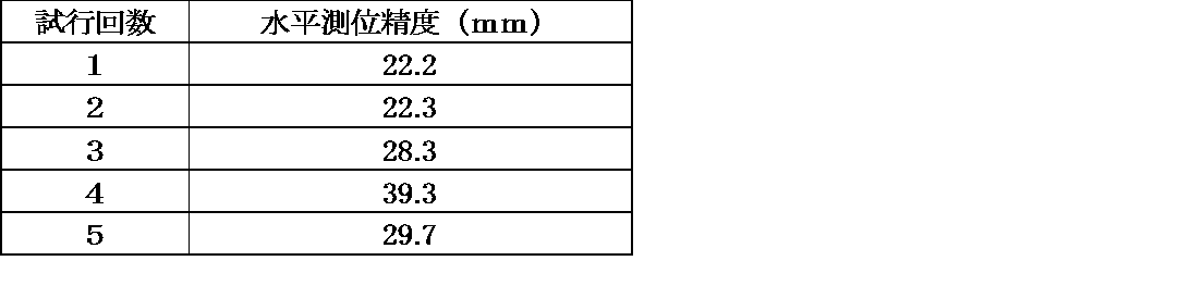
図26は、この比較結果を示した図である。図26の左側はマーカを用いた初期化を行わなかった場合である。60秒では十分に収束せず、1mを超える誤差が出ていることが分かる。これに対し、図26の右側に示したマーカを用いて初期化を行った場合では、瞬時に収束して水平誤差3cm以内の精度が達成されていることが分かる。表1に、5回の試行実験での各試行における水平測位精度を示す。表1から分かるように、非常に高い精度が得られた。
次に、図22の(C)に示した、マーカの設置位置及び姿勢の計測実験について説明する。上記(A)の実験と同様に、移動体をスタート地点まで前進させ、PPPによる衛星測位及びマーカの計測を開始し、初期化を行う。(A)の初期化の場合とは異なり、マーカの計測を継続したまま移動体の前進を開始する。マーカがカメラの視野から外れないように注意しながら、マーカの手前約1mの地点まで前進する。これにより、移動中に測位データ及び測位データに同期したマーカ計測データを取得することができる。
前述したマーカの設置位置及び姿勢の推定方法により、取得したデータと式1に基づいてマーカの位置及び姿勢を推定し、水平位置誤差7.2mm、方位角誤差0.081度という結果が得られた。
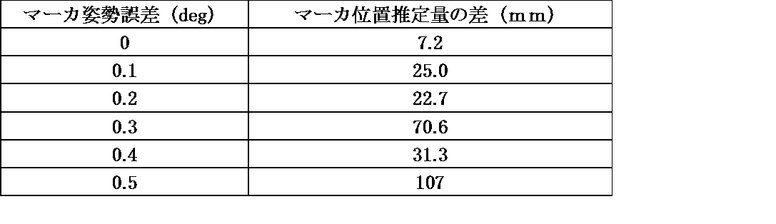
次に、図22の(B)に示した初期化結果の検証実験について説明する。マーカの設置姿勢(方位角)を人為的に0.1度から0.5度まで0.1度刻みで変化させ、それぞれについて設置位置及び姿勢の計測実験と同様の手順で測位データ及びマーカの計測データを取得し、マーカの設置位置を推定した。表2に、マーカ位置の推定量の差(初期化の際に用いたマーカ位置と推定位置との差)を示す。表2の結果から分かるように、位置の推定量に適切な閾値(例えば20mm)を設け、これを超えた場合にはマーカの設置姿勢が変化したと推定し、この閾値以下であればマーカの設置姿勢に変化がないと推定することで、マーカの設置姿勢が変化したかどうかを検出することが可能であることが示される。
(測位パラメータ推定方法)
ところで、測位パラメータの推定は、通常は逐次処理(フィルタ)によって行う。上記各実施例でも、パラメータの推定にはフィルタ(拡張カルマンフィルタ)を用いており、マーカの観測によって求められたGNSSアンテナの位置の推定値をフィルタの初期値として入力することで初期化している。しかし、測位パラメータの推定はフィルタ以外の方法によっても可能である。また、フィルタも含めて、マーカとの組み合わせによってさらにパラメータの推定精度の向上及び推定時間の短縮が期待できる。以下に、そのような推定方法の具体的な例を挙げる。なお、以下では、実施形態2に示したように、移動体が移動しながら衛星測位とマーカの観測とを同期して実行し、両方の観測データを得られるものとする。
ところで、測位パラメータの推定は、通常は逐次処理(フィルタ)によって行う。上記各実施例でも、パラメータの推定にはフィルタ(拡張カルマンフィルタ)を用いており、マーカの観測によって求められたGNSSアンテナの位置の推定値をフィルタの初期値として入力することで初期化している。しかし、測位パラメータの推定はフィルタ以外の方法によっても可能である。また、フィルタも含めて、マーカとの組み合わせによってさらにパラメータの推定精度の向上及び推定時間の短縮が期待できる。以下に、そのような推定方法の具体的な例を挙げる。なお、以下では、実施形態2に示したように、移動体が移動しながら衛星測位とマーカの観測とを同期して実行し、両方の観測データを得られるものとする。
第1の例は、フィルタを用いる場合である。カルマンフィルタやその派生手法において、マーカの観測によって得られた移動体の相対位置/速度や相対姿勢/角速度など情報をシステムのダイナミクスに取り込むなどにより、推定精度の向上を図ることができる。
第2の例は、バッチ処理によるものである。一定期間の衛星測位データとマーカ観測データとを一括して扱い、非線形最小二乗法などの手法によってパラメータを推定することができる。
第3の例は、ハイブリッド手法である。すなわち、フィルタとバッチ処理の両方の側面を持つ手法である。これは、ロボティクスの分野において、smoothing and mapping と呼ばれている手法に相当する。一定期間のデータを用いてバッチ的に推定を行うとともに、時間経過とともに対象とする期間をスライドさせて行くなどにより、精度の向上と計算負荷の軽減を図ることができる。
(実施形態4についての補足)
実施形態4に示した「マーカ設置姿勢誤差検出手法」を繰り返し実行することで、マーカの設置姿勢誤差がアンテナの位置推定に求められる許容範囲より大きい場合にも初期化を行うことが可能となる。また実施形態4の方法によってマーカ位置の推定量の差を求めることができる。この値は、理論上は、マーカ設置姿勢の誤差の増大に伴って単調増加する。そこで、マーカ位置の推定量の差から、マーカ設置姿勢の誤差(のおおよその値)を推定することが可能である。この推定された誤差分を、衛星測位の初期化を行う際に用いたマーカ設置姿勢に対して補正し、補正後のマーカ設置姿勢を用いて後処理計算により再度測位の初期化とマーカ設置姿勢の誤差の検出計算を行う。これは、測位データとマーカの観測データを同期して取得してあるため、後処理による計算が可能である。こうして求めたマーカ位置の推定量の差は、初回に求めた値よりも小さくなっていることが期待できる。このようなプロセスを繰り返すことによって、最終的にマーカの設置姿勢の誤差をアンテナ位置の推定に求められる許容範囲内に抑えることができる。
実施形態4に示した「マーカ設置姿勢誤差検出手法」を繰り返し実行することで、マーカの設置姿勢誤差がアンテナの位置推定に求められる許容範囲より大きい場合にも初期化を行うことが可能となる。また実施形態4の方法によってマーカ位置の推定量の差を求めることができる。この値は、理論上は、マーカ設置姿勢の誤差の増大に伴って単調増加する。そこで、マーカ位置の推定量の差から、マーカ設置姿勢の誤差(のおおよその値)を推定することが可能である。この推定された誤差分を、衛星測位の初期化を行う際に用いたマーカ設置姿勢に対して補正し、補正後のマーカ設置姿勢を用いて後処理計算により再度測位の初期化とマーカ設置姿勢の誤差の検出計算を行う。これは、測位データとマーカの観測データを同期して取得してあるため、後処理による計算が可能である。こうして求めたマーカ位置の推定量の差は、初回に求めた値よりも小さくなっていることが期待できる。このようなプロセスを繰り返すことによって、最終的にマーカの設置姿勢の誤差をアンテナ位置の推定に求められる許容範囲内に抑えることができる。
201 移動体
202 カメラ
203 GNSSアンテナ
211 視覚マーカ
212 支持台
202 カメラ
203 GNSSアンテナ
211 視覚マーカ
212 支持台
Claims (14)
- 衛星測位部、マーカ検出部、及び演算部を有する移動体と、
予め地球固定座標系における位置及び姿勢が測定されているマーカと、を備え、
前記演算部は、前記マーカ検出部によって検出された前記マーカの位置及び姿勢に基づいて前記移動体の地球固定座標系における位置を算出し、
前記衛星測位部は、前記演算部が算出した前記移動体の位置に関する情報を受け取って、衛星測位処理を実行する衛星測位システム。 - 前記マーカ検出部は、前記マーカの画像を撮影する撮影装置を含んでいる、請求項1に記載の衛星測位システム。
- 衛星測位部、マーカ検出部、及び演算部を有する移動体と、
予め地球固定座標系における位置が測定されている複数のマーカと、を備え、
前記演算部は、前記マーカ検出部によって検出された前記複数のマーカの位置に基づいて前記移動体の地球固定座標系における位置を算出し、
前記衛星測位部は、前記演算部が算出した前記移動体の位置に関する情報を受け取って、衛星測位処理を実行する衛星測位システム。 - 地球固定座標系におけるマーカの位置、又は前記マーカの姿勢を予め測定するステップと、
移動体に搭載されたマーカ検出部により前記マーカを検出し、それに基づいて移動体の地球固定座標系における位置を算出するステップと、
前記移動体の地球固定座標系における位置に関する情報を移動体に搭載された衛星測位部に供給し、衛星測位処理を実行するステップと、
を備える、衛星測位方法。 - 衛星測位部、マーカ検出部、及び演算部を有する移動体によって、地上に固定されたマーカの位置及び姿勢を測定する方法であって、
前記移動体の地球固定座標系における位置を取得するステップと、
前記移動体を任意の経路で移動させるステップと、
前記移動体の移動中に、複数の地点のそれぞれにおいて、前記マーカ検出部により前記マーカを観測して前記マーカの前記マーカ検出部に対する相対位置及び相対姿勢を計測し、その計測結果に基づいて各観測地点における前記移動体の前記マーカに対する相対位置を算出するステップと、
前記各観測地点での、前記移動体の地球固定座標系における位置と、前記移動体の前記マーカに対する算出された相対位置を用いて、前記マーカの地球固定座標系における位置及び姿勢を推定するステップと、
を備える、マーカの位置及び姿勢を測定する方法。 - 前記各観測地点での、前記移動体の地球固定座標系における位置と、前記移動体の前記マーカに対する算出された相対位置との間の距離を算出し、前記各観測地点の全てにおける前記距離の総和に基づく評価関数を最小とするような前記マーカの地球固定座標系における位置及び姿勢を推定値とする、請求項5に記載の方法。
- 衛星測位部、マーカ検出部、及び演算部を有する移動体によって、地上に固定されたマーカの位置及び姿勢を測定する方法であって、
前記移動体の地球固定座標系における位置を取得するステップと、
前記マーカに対する任意の位置に複数の仮想マーカを設定するステップと、
前記移動体を任意の経路で移動させるステップと、
前記移動体の移動中に、複数の地点のそれぞれにおいて、前記マーカ検出部により前記マーカを観測して前記マーカの位置及び姿勢を計測し、その結果に基づいてそれぞれの地点において前記複数の仮想マーカの移動体に対する相対位置を算出し、各観測地点において算出された前記複数の仮想マーカの算出相対位置から前記複数の仮想マーカの地球固定座標系における位置を推定するステップと、
前記複数の仮想マーカの推定された位置から、前記マーカの位置及び姿勢を推定するステップと、
を備える、マーカの位置及び姿勢を測定する方法。 - 前記任意の経路は、前記マーカからみた遠位点と近位点とを結ぶ直線であり、前記複数の仮想マーカは、前記マーカとそれぞれの前記仮想マーカを結ぶ直線上で前記移動体から前記直線に下ろした垂線と前記直線との交点に位置する、請求項7に記載の方法。
- 衛星測位部、マーカ検出部、及び演算部を有する移動体によって、地上に固定されたマーカの位置及び姿勢を評価する方法であって、
地上に固定されたマーカの位置及び姿勢を、記憶部に予め記憶しておくステップと、
前記記憶部に予め記憶された前記マーカの位置及び姿勢と、請求項5乃至8のいずれか一項に記載の方法により測定された前記マーカの位置及び姿勢とを比較するステップと、
を備える、マーカの位置及び姿勢を評価する方法。 - 衛星測位部、マーカ検出部、及び演算部を有する移動体と、
予め地球固定座標系における位置及び姿勢が測定されているマーカと、を備え、
前記演算部は、前記マーカ検出部によって検出された前記マーカから前記移動体の位置を推定し、
前記衛星測位部は前記移動体の当該推定位置に関する情報を受け取って初期化を行い、前記演算部は、
当該初期化後に前記マーカ検出部が前記マーカを観測することによって前記マーカの位置を推定し、そのマーカの推定位置と予め前記移動体が保持している前記マーカの位置に関する情報を比較することによって、あらかじめ前記移動体が保持している前記マーカの姿勢に誤差があるか否かを判定する、衛星測位システム。 - 前記衛星測位部は、単独搬送波位相測位(PPP)方式による衛星測位処理を実行するものである、請求項1乃至3及び10のいずれか一項に記載の衛星測位システム。
- 衛星測位部、マーカ検出部、及び演算部を有する移動体によって、あらかじめ前記移動体が保持しているマーカの姿勢誤差を判定する方法であって、
予めマーカの位置及び姿勢を測定し、その結果を前記移動体の演算部が保持するステップと、
前記マーカ検出部が前記マーカを観測し、その結果から前記演算部が前記移動体の位置を推定するステップと、
前記衛星測位部が、前記移動体の当該推定位置に関する情報を受け取って初期化を行うステップと、
前記初期化の後に前記マーカ検出部が前記マーカを観測し、その結果に基づいて前記マーカの位置を推定するステップと、
前記演算部が、前記推定された前記マーカの位置を前記演算部が保持するマーカの位置と比較して、その比較結果に基づいてマーカの姿勢に誤差があるか否かを判定するステップと、
を備える、あらかじめ前記移動体が保持している前記マーカの姿勢に誤差があるか否かを判定する方法。 - 前記衛星測位部は、単独搬送波位相測位(PPP)方式による衛星測位処理を実行するものである、請求項4乃至9及び12のいずれか一項に記載の方法。
- 測定及び/又は評価された前記マーカの地球固定座標系における位置及び姿勢の情報を、前記移動体と、前記移動体と異なる移動体との間で共有する、請求項5乃至9、12、13のいずれか一項に記載の方法。
Applications Claiming Priority (4)
| Application Number | Priority Date | Filing Date | Title |
|---|---|---|---|
| JP2016133721 | 2016-07-05 | ||
| JP2016-133721 | 2016-07-05 | ||
| JP2017-040914 | 2017-03-03 | ||
| JP2017040914A JP6708328B2 (ja) | 2016-07-05 | 2017-03-03 | 衛星測位システム及び衛星測位方法 |
Publications (1)
| Publication Number | Publication Date |
|---|---|
| WO2018008627A1 true WO2018008627A1 (ja) | 2018-01-11 |
Family
ID=60912719
Family Applications (1)
| Application Number | Title | Priority Date | Filing Date |
|---|---|---|---|
| PCT/JP2017/024469 Ceased WO2018008627A1 (ja) | 2016-07-05 | 2017-07-04 | 衛星測位システム及び衛星測位方法 |
Country Status (1)
| Country | Link |
|---|---|
| WO (1) | WO2018008627A1 (ja) |
Cited By (5)
| Publication number | Priority date | Publication date | Assignee | Title |
|---|---|---|---|---|
| JP2019211448A (ja) * | 2018-06-08 | 2019-12-12 | 清水建設株式会社 | 相互位置取得システム |
| EP3828499A1 (en) * | 2019-11-27 | 2021-06-02 | Novatron Oy | Method for determining location and orientation of machine |
| JP2022502722A (ja) * | 2019-11-07 | 2022-01-11 | 広東工業大学Guangdong University Of Technology | 自律運転車両の屋外運転システム |
| CN115267862A (zh) * | 2022-07-26 | 2022-11-01 | 北京理工大学 | 基于多传感器输入融合的室内/室外切换定位方法和系统 |
| CN115390117A (zh) * | 2022-10-27 | 2022-11-25 | 湖南山和勘测设计有限公司 | 一种精密单点定位变形监测方法及装置 |
Citations (4)
| Publication number | Priority date | Publication date | Assignee | Title |
|---|---|---|---|---|
| JPH10300493A (ja) * | 1997-04-28 | 1998-11-13 | Honda Motor Co Ltd | 車両位置推定装置と車両位置推定方法、および、走行車線維持装置と走行車線維持方法 |
| JP2010025872A (ja) * | 2008-07-24 | 2010-02-04 | Cosmo Ec Co Ltd | 芝刈機、目標板の位置座標の測位方法 |
| US20130162469A1 (en) * | 2010-09-16 | 2013-06-27 | Leica Geosystems Ag | Geodetic survey system having a camera integrated in a remote control unit |
| WO2017024358A1 (en) * | 2015-08-13 | 2017-02-16 | Propeller Aerobotics Pty Ltd | Integrated visual geo-referencing target unit and method of operation |
-
2017
- 2017-07-04 WO PCT/JP2017/024469 patent/WO2018008627A1/ja not_active Ceased
Patent Citations (4)
| Publication number | Priority date | Publication date | Assignee | Title |
|---|---|---|---|---|
| JPH10300493A (ja) * | 1997-04-28 | 1998-11-13 | Honda Motor Co Ltd | 車両位置推定装置と車両位置推定方法、および、走行車線維持装置と走行車線維持方法 |
| JP2010025872A (ja) * | 2008-07-24 | 2010-02-04 | Cosmo Ec Co Ltd | 芝刈機、目標板の位置座標の測位方法 |
| US20130162469A1 (en) * | 2010-09-16 | 2013-06-27 | Leica Geosystems Ag | Geodetic survey system having a camera integrated in a remote control unit |
| WO2017024358A1 (en) * | 2015-08-13 | 2017-02-16 | Propeller Aerobotics Pty Ltd | Integrated visual geo-referencing target unit and method of operation |
Cited By (7)
| Publication number | Priority date | Publication date | Assignee | Title |
|---|---|---|---|---|
| JP2019211448A (ja) * | 2018-06-08 | 2019-12-12 | 清水建設株式会社 | 相互位置取得システム |
| JP7061933B2 (ja) | 2018-06-08 | 2022-05-02 | 清水建設株式会社 | 相互位置取得システム |
| JP2022502722A (ja) * | 2019-11-07 | 2022-01-11 | 広東工業大学Guangdong University Of Technology | 自律運転車両の屋外運転システム |
| EP3828499A1 (en) * | 2019-11-27 | 2021-06-02 | Novatron Oy | Method for determining location and orientation of machine |
| US11796316B2 (en) | 2019-11-27 | 2023-10-24 | Novatron Oy | Method for determining location and orientation of machine |
| CN115267862A (zh) * | 2022-07-26 | 2022-11-01 | 北京理工大学 | 基于多传感器输入融合的室内/室外切换定位方法和系统 |
| CN115390117A (zh) * | 2022-10-27 | 2022-11-25 | 湖南山和勘测设计有限公司 | 一种精密单点定位变形监测方法及装置 |
Similar Documents
| Publication | Publication Date | Title |
|---|---|---|
| JP6708328B2 (ja) | 衛星測位システム及び衛星測位方法 | |
| US10338228B2 (en) | Portable GNSS survey system | |
| US11237005B2 (en) | Method and arrangement for sourcing of location information, generating and updating maps representing the location | |
| US10563980B2 (en) | Enhanced remote surveying systems and methods | |
| US9377298B2 (en) | Surface determination for objects by means of geodetically precise single point determination and scanning | |
| EP1019862B1 (en) | Method and apparatus for generating navigation data | |
| CA2902608C (en) | System and method for heavy equipment navigation and working edge positioning | |
| US20140210663A1 (en) | Measuring system and method for determining new points | |
| WO2018008627A1 (ja) | 衛星測位システム及び衛星測位方法 | |
| EP3911968B1 (en) | Locating system | |
| CN105509721B (zh) | 测量装置 | |
| CN116972819B (zh) | 放样方法及测量系统 | |
| CN112269202A (zh) | 一种运动载体辅助的空间基准传递系统及方法 | |
| US10514467B2 (en) | Up sampling reference station data | |
| WO2021220420A1 (ja) | 計測装置、計測方法、及びプログラム | |
| JP2021143861A (ja) | 情報処理装置、情報処理方法及び情報処理システム | |
| RU2515469C1 (ru) | Способ навигации летательных аппаратов | |
| KR102473765B1 (ko) | 차량용 측위 장치 및 방법 | |
| JP2018036151A (ja) | ランドマークを用いた測位方法 | |
| JP6501437B1 (ja) | 衛星測位システム及び衛星測位方法 | |
| Chu et al. | The performance of a tight INS/GNSS/photogrammetric integration scheme for land based MMS applications in GNSS denied environments | |
| Niu et al. | Visual RTK positioning enhanced by pole motion constraint | |
| Chu et al. | The performance analysis of a portable mobile mapping system with different gnss processing strategies | |
| Gonçalves et al. | Application of a low cost mobile mapping system to coastal monitoring | |
| Huang et al. | Improving the performance of MEMS IMU/GPS pos systems for land based MMS utilizing tightly coupled integration and odometer |
Legal Events
| Date | Code | Title | Description |
|---|---|---|---|
| 121 | Ep: the epo has been informed by wipo that ep was designated in this application |
Ref document number: 17824230 Country of ref document: EP Kind code of ref document: A1 |
|
| NENP | Non-entry into the national phase |
Ref country code: DE |
|
| 122 | Ep: pct application non-entry in european phase |
Ref document number: 17824230 Country of ref document: EP Kind code of ref document: A1 |