WO2018003205A1 - 映像表示機能付き眼鏡 - Google Patents
映像表示機能付き眼鏡 Download PDFInfo
- Publication number
- WO2018003205A1 WO2018003205A1 PCT/JP2017/011026 JP2017011026W WO2018003205A1 WO 2018003205 A1 WO2018003205 A1 WO 2018003205A1 JP 2017011026 W JP2017011026 W JP 2017011026W WO 2018003205 A1 WO2018003205 A1 WO 2018003205A1
- Authority
- WO
- WIPO (PCT)
- Prior art keywords
- optical element
- image
- glasses
- video display
- mode
- Prior art date
- Legal status (The legal status is an assumption and is not a legal conclusion. Google has not performed a legal analysis and makes no representation as to the accuracy of the status listed.)
- Ceased
Links
Images





Classifications
-
- G—PHYSICS
- G02—OPTICS
- G02B—OPTICAL ELEMENTS, SYSTEMS OR APPARATUS
- G02B27/00—Optical systems or apparatus not provided for by any of the groups G02B1/00 - G02B26/00, G02B30/00
- G02B27/01—Head-up displays
- G02B27/017—Head mounted
- G02B27/0172—Head mounted characterised by optical features
-
- A—HUMAN NECESSITIES
- A61—MEDICAL OR VETERINARY SCIENCE; HYGIENE
- A61B—DIAGNOSIS; SURGERY; IDENTIFICATION
- A61B3/00—Apparatus for testing the eyes; Instruments for examining the eyes
-
- G—PHYSICS
- G02—OPTICS
- G02B—OPTICAL ELEMENTS, SYSTEMS OR APPARATUS
- G02B23/00—Telescopes, e.g. binoculars; Periscopes; Instruments for viewing the inside of hollow bodies; Viewfinders; Optical aiming or sighting devices
- G02B23/12—Telescopes, e.g. binoculars; Periscopes; Instruments for viewing the inside of hollow bodies; Viewfinders; Optical aiming or sighting devices with means for image conversion or intensification
- G02B23/125—Telescopes, e.g. binoculars; Periscopes; Instruments for viewing the inside of hollow bodies; Viewfinders; Optical aiming or sighting devices with means for image conversion or intensification head-mounted
-
- G—PHYSICS
- G02—OPTICS
- G02B—OPTICAL ELEMENTS, SYSTEMS OR APPARATUS
- G02B27/00—Optical systems or apparatus not provided for by any of the groups G02B1/00 - G02B26/00, G02B30/00
- G02B27/02—Viewing or reading apparatus
- G02B27/04—Viewing or reading apparatus having collapsible parts
-
- G—PHYSICS
- G02—OPTICS
- G02B—OPTICAL ELEMENTS, SYSTEMS OR APPARATUS
- G02B30/00—Optical systems or apparatus for producing three-dimensional [3D] effects, e.g. stereoscopic images
- G02B30/20—Optical systems or apparatus for producing three-dimensional [3D] effects, e.g. stereoscopic images by providing first and second parallax images to an observer's left and right eyes
- G02B30/34—Stereoscopes providing a stereoscopic pair of separated images corresponding to parallactically displaced views of the same object, e.g. three-dimensional [3D] slide viewers
-
- G—PHYSICS
- G02—OPTICS
- G02F—OPTICAL DEVICES OR ARRANGEMENTS FOR THE CONTROL OF LIGHT BY MODIFICATION OF THE OPTICAL PROPERTIES OF THE MEDIA OF THE ELEMENTS INVOLVED THEREIN; NON-LINEAR OPTICS; FREQUENCY-CHANGING OF LIGHT; OPTICAL LOGIC ELEMENTS; OPTICAL ANALOGUE/DIGITAL CONVERTERS
- G02F1/00—Devices or arrangements for the control of the intensity, colour, phase, polarisation or direction of light arriving from an independent light source, e.g. switching, gating or modulating; Non-linear optics
- G02F1/01—Devices or arrangements for the control of the intensity, colour, phase, polarisation or direction of light arriving from an independent light source, e.g. switching, gating or modulating; Non-linear optics for the control of the intensity, phase, polarisation or colour
- G02F1/13—Devices or arrangements for the control of the intensity, colour, phase, polarisation or direction of light arriving from an independent light source, e.g. switching, gating or modulating; Non-linear optics for the control of the intensity, phase, polarisation or colour based on liquid crystals, e.g. single liquid crystal display cells
-
- G—PHYSICS
- G03—PHOTOGRAPHY; CINEMATOGRAPHY; ANALOGOUS TECHNIQUES USING WAVES OTHER THAN OPTICAL WAVES; ELECTROGRAPHY; HOLOGRAPHY
- G03H—HOLOGRAPHIC PROCESSES OR APPARATUS
- G03H1/00—Holographic processes or apparatus using light, infrared or ultraviolet waves for obtaining holograms or for obtaining an image from them; Details peculiar thereto
- G03H1/04—Processes or apparatus for producing holograms
- G03H1/08—Synthesising holograms, i.e. holograms synthesized from objects or objects from holograms
- G03H1/0808—Methods of numerical synthesis, e.g. coherent ray tracing [CRT], diffraction specific
-
- G—PHYSICS
- G03—PHOTOGRAPHY; CINEMATOGRAPHY; ANALOGOUS TECHNIQUES USING WAVES OTHER THAN OPTICAL WAVES; ELECTROGRAPHY; HOLOGRAPHY
- G03H—HOLOGRAPHIC PROCESSES OR APPARATUS
- G03H1/00—Holographic processes or apparatus using light, infrared or ultraviolet waves for obtaining holograms or for obtaining an image from them; Details peculiar thereto
- G03H1/22—Processes or apparatus for obtaining an optical image from holograms
- G03H1/2294—Addressing the hologram to an active spatial light modulator
-
- G—PHYSICS
- G02—OPTICS
- G02B—OPTICAL ELEMENTS, SYSTEMS OR APPARATUS
- G02B27/00—Optical systems or apparatus not provided for by any of the groups G02B1/00 - G02B26/00, G02B30/00
- G02B27/01—Head-up displays
- G02B27/0101—Head-up displays characterised by optical features
- G02B2027/0118—Head-up displays characterised by optical features comprising devices for improving the contrast of the display / brillance control visibility
-
- G—PHYSICS
- G02—OPTICS
- G02B—OPTICAL ELEMENTS, SYSTEMS OR APPARATUS
- G02B27/00—Optical systems or apparatus not provided for by any of the groups G02B1/00 - G02B26/00, G02B30/00
- G02B27/01—Head-up displays
- G02B27/0101—Head-up displays characterised by optical features
- G02B2027/0132—Head-up displays characterised by optical features comprising binocular systems
- G02B2027/0134—Head-up displays characterised by optical features comprising binocular systems of stereoscopic type
-
- G—PHYSICS
- G02—OPTICS
- G02B—OPTICAL ELEMENTS, SYSTEMS OR APPARATUS
- G02B27/00—Optical systems or apparatus not provided for by any of the groups G02B1/00 - G02B26/00, G02B30/00
- G02B27/01—Head-up displays
- G02B27/0101—Head-up displays characterised by optical features
- G02B2027/0138—Head-up displays characterised by optical features comprising image capture systems, e.g. camera
-
- G—PHYSICS
- G02—OPTICS
- G02B—OPTICAL ELEMENTS, SYSTEMS OR APPARATUS
- G02B27/00—Optical systems or apparatus not provided for by any of the groups G02B1/00 - G02B26/00, G02B30/00
- G02B27/01—Head-up displays
- G02B27/017—Head mounted
- G02B27/0172—Head mounted characterised by optical features
- G02B2027/0174—Head mounted characterised by optical features holographic
-
- G—PHYSICS
- G02—OPTICS
- G02B—OPTICAL ELEMENTS, SYSTEMS OR APPARATUS
- G02B27/00—Optical systems or apparatus not provided for by any of the groups G02B1/00 - G02B26/00, G02B30/00
- G02B27/01—Head-up displays
- G02B27/017—Head mounted
- G02B2027/0178—Eyeglass type
-
- G—PHYSICS
- G02—OPTICS
- G02C—SPECTACLES; SUNGLASSES OR GOGGLES INSOFAR AS THEY HAVE THE SAME FEATURES AS SPECTACLES; CONTACT LENSES
- G02C2202/00—Generic optical aspects applicable to one or more of the subgroups of G02C7/00
- G02C2202/22—Correction of higher order and chromatic aberrations, wave front measurement and calculation
-
- G—PHYSICS
- G02—OPTICS
- G02C—SPECTACLES; SUNGLASSES OR GOGGLES INSOFAR AS THEY HAVE THE SAME FEATURES AS SPECTACLES; CONTACT LENSES
- G02C7/00—Optical parts
- G02C7/02—Lenses; Lens systems ; Methods of designing lenses
- G02C7/08—Auxiliary lenses; Arrangements for varying focal length
- G02C7/081—Ophthalmic lenses with variable focal length
- G02C7/083—Electrooptic lenses
-
- G—PHYSICS
- G02—OPTICS
- G02C—SPECTACLES; SUNGLASSES OR GOGGLES INSOFAR AS THEY HAVE THE SAME FEATURES AS SPECTACLES; CONTACT LENSES
- G02C7/00—Optical parts
- G02C7/02—Lenses; Lens systems ; Methods of designing lenses
- G02C7/08—Auxiliary lenses; Arrangements for varying focal length
- G02C7/086—Auxiliary lenses located directly on a main spectacle lens or in the immediate vicinity of main spectacles
-
- G—PHYSICS
- G03—PHOTOGRAPHY; CINEMATOGRAPHY; ANALOGOUS TECHNIQUES USING WAVES OTHER THAN OPTICAL WAVES; ELECTROGRAPHY; HOLOGRAPHY
- G03H—HOLOGRAPHIC PROCESSES OR APPARATUS
- G03H2225/00—Active addressable light modulator
- G03H2225/30—Modulation
- G03H2225/32—Phase only
-
- G—PHYSICS
- G03—PHOTOGRAPHY; CINEMATOGRAPHY; ANALOGOUS TECHNIQUES USING WAVES OTHER THAN OPTICAL WAVES; ELECTROGRAPHY; HOLOGRAPHY
- G03H—HOLOGRAPHIC PROCESSES OR APPARATUS
- G03H2270/00—Substrate bearing the hologram
- G03H2270/55—Substrate bearing the hologram being an optical element, e.g. spectacles
Definitions
- the present invention relates to eyeglasses with an image display function for showing a wearer an image displayed or projected on an eyeglass lens.
- Patent Document 1 proposes a glasses-type display device that captures a scene in front of the wearer with an imaging unit and displays the image on a glasses-type display unit.
- Patent Document 2 a glasses-type display device that guides an image displayed on a display unit by a plate-like member and reflects the image toward the wearer's eye by a hologram element provided in the plate-like member.
- the plate-like member has optical power.
- JP 2008-83289 A Japanese Patent Application Laid-Open No. 2002-98928
- the plate-like member has optical power as described above.
- this optical power is fixed, it should be changed according to the eyesight of the wearer. I can't.
- the wearer cannot correct the appearance of the virtual image formed by the hologram element even if the wearer can clearly see the scenery in front.
- the present invention has both a video display function and a glasses function, can change the refractive power in accordance with the wearer's visual acuity, and the like, and is further reproduced by the video display function.
- An object of the present invention is to provide eyeglasses with an image display function that can correct the appearance of the image.
- the first spectacles with a video display function of the present invention display or reflect a spectacle main body, a first transmissive optical element that transmits an image of a subject and can change a refractive power, and an image using a video signal. And a second transmissive optical element that transmits the image of the subject, a video display mode in which an image is displayed or reflected by the second transmissive optical element and incident on the eye of the wearer of the spectacle body,
- a control unit that switches between a spectacles mode in which an image of a subject that has passed through the second transmissive optical element and the second transmissive optical element is incident on the eyes of the wearer, and the first transmissive optical element includes: The second transmissive optical element is disposed closer to the wearer.
- a liquid crystal lens can be used as the first transmissive optical element.
- the liquid crystal lens has a plurality of divided regions, and the refractive index can be changed for each divided region.
- the transmission mode for transmitting the light for forming the image of the subject and the light for forming the image of the subject are located closer to the subject than the second transmission type optical element.
- the transmission mode for transmitting the light for forming the image of the subject and the light for forming the image of the subject are located closer to the subject than the second transmission type optical element.
- control unit can control the third optical element to the transmission mode when the power is turned off.
- the first glasses with a video display function further includes a refractive power information acquisition unit that acquires refractive power information of the first transmission optical element, and the control unit is acquired by the refractive power information acquisition unit.
- the refractive power of the first transmission optical element can be controlled using the refractive power information.
- a plurality of fixed focal length lenses having different refractive powers can be exchanged on the wearer side of the first transmissive optical element.
- a phase modulation type computer generated hologram display element can be used as the second transmission type optical element.
- the phase modulation type computer generated hologram display element can have a plurality of display pixels.
- the phase modulation type computer generated hologram display element can display a computer generated hologram interference pattern using a video signal.
- the phase modulation type computer generated hologram display element can reproduce the video as a planar image at a position away from the phase modulation type computer generated hologram display element.
- a reference light irradiating unit for irradiating the phase modulation type computer generated hologram display element with reference light can be provided.
- a thin hologram element can be used as the phase modulation type computer generated hologram display element.
- a wavelength-selective reflecting member can be provided on the subject side of the thin hologram element, and the wavelength-selective reflecting member reflects the reference light and the reference light. It is possible to transmit light of other wavelengths.
- the reference light irradiating unit irradiates the phase modulation type computer generated hologram display element with three types of reference lights having different wavelengths in a time-sharing manner.
- the modulation type computer generated hologram display element can display the computer generated hologram interference pattern corresponding to the reference light of each wavelength in a time-sharing manner.
- the reference light irradiating unit simultaneously irradiates the phase modulation type computer generated hologram display element with three types of reference lights having different wavelengths, and the phase modulation type
- the computer generated hologram display element can display a computer generated hologram interference pattern simulating multiple exposures of three types of reference light.
- the control unit turns off the reference light irradiation unit in the glasses mode, and turns on the reference light irradiation unit in the video display mode. be able to.
- the reference light irradiation unit can irradiate the linearly polarized reference light to the phase modulation type computer generated hologram display element.
- the control unit can uniformly control the refractive index of the second transmission optical element in the spectacles mode.
- the first glasses with a video display function of the present invention includes a distance information acquisition unit that acquires distance information between the wearer and the subject, and the control unit acquires the distance acquired by the distance information acquisition unit. Information can be used to control the refractive power of the first transmissive optical element.
- the control unit makes the refractive indexes of the first transmissive optical element and the second transmissive optical element uniform when the power is turned off. Can be controlled.
- the first transmission optical element can have two liquid crystal layers whose orientation directions are orthogonal to each other.
- the first transmission optical element has two liquid crystal layers having the same alignment direction, and 1 ⁇ 2 between the two liquid crystal layers.
- a wave plate can be provided.
- the first transmission optical element may have a plurality of sets of two liquid crystal layers.
- control unit can generate the phase distribution that corrects the abnormality of the wavefront aberration of the eye by controlling the first transmissive optical element.
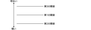
- the control unit obtains information on the brightness of the wearer's surrounding environment, and the brightness is equal to or less than a preset first threshold value.
- the glasses mode can be switched to the video display mode.
- the control unit when the control unit is set to the spectacles mode in which the brightness is larger than the first threshold, the brightness is smaller than the first threshold.
- the glasses mode is switched to the video display mode, and when the brightness is set to the video display mode that is less than or equal to the first threshold value, the brightness is larger than the first threshold value.
- the threshold value exceeds the threshold value, the video display mode can be switched to the glasses mode.
- the control unit may be configured such that the brightness is between the first threshold value and the second threshold value, and the brightness is between the first threshold value and the third threshold value. If it is between the threshold values, the transmittance of the third optical element with respect to the light forming the image of the subject can be changed continuously or stepwise.
- the control unit may be configured such that the brightness is between the first threshold value and the second threshold value, and the brightness is between the first threshold value and the third threshold value. If it is between the threshold values, an image is displayed on the second transmissive optical element, and an image of the subject transmitted through the first transmissive optical element and the second transmissive optical element is displayed on the eye of the wearer. It is possible to control to an intermediate mode that enters the light.
- an imaging unit for imaging a subject and outputting a video signal can be provided.
- the imaging unit can have a scaling function.
- a second spectacles with a video display function of the present invention is a transmissive optical element that transmits a spectacle main body and an image of a subject and can change a refractive power, and displays a video using a video signal.
- An optical element, an image display mode in which an image is displayed by the transmissive optical element and incident on the eye of the wearer of the spectacle body, and an eyeglass mode in which an image of a subject transmitted through the transmissive optical element is incident on the eye of the wearer And a control unit for controlling the switching so as to be switchable.
- the first transmissive optical element that transmits the image of the subject and that can change the refractive power, and displays or reflects the video using the video signal
- a second transmissive optical element that transmits the image of the subject. Then, an image display mode in which an image is displayed or reflected by the second transmissive optical element and incident on the eye of the wearer of the spectacle body, and the first transmissive optical element and the second transmissive optical element are transmitted. Since the spectacles mode in which the image of the subject is incident on the wearer's eye can be switched, both the video display function and the spectacle function can be provided, and the refractive power can be changed according to the visual acuity of the wearer. it can.
- the first transmissive optical element is arranged closer to the wearer than the second transmissive optical element, the appearance of the video reproduced by the video display function can be corrected.
- the spectacle main body and a transmissive optical element that transmits an image of a subject and can change a refractive power, and displays an image using a video signal.
- a transmissive optical element Switching between the video display mode in which video is displayed by the transmissive optical element and incident on the eye of the wearer of the spectacle body and the spectacle mode in which the image of the subject that has passed through the transmissive optical element is incident on the eye of the wearer Since it was made possible, it has both a video display function and a glasses function, and the refractive power can be changed according to the eyesight of the wearer.
- the perspective view which shows schematic structure of one Embodiment of the spectacles with a video display function of this invention.
- the figure which shows an example of a structure of a lens part The figure for demonstrating the effect
- the block diagram which shows the electrical constitution of one Embodiment of the spectacles with a video display function of this invention.
- the figure which shows the fixed focal length lens which can be attached or detached to a lens part The figure which shows other embodiment of the 2nd transmission type optical element.
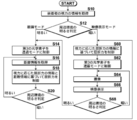
- FIGS. Flowchart for explaining the operation of the glasses with video display function in the case of the configuration shown in FIGS.
- FIG. 1 is a perspective view showing a schematic configuration of eyeglasses 1 with a video display function of the present embodiment.
- “front”, “rear”, “left”, “right”, “upper”, and “lower” refer to a state in which glasses with video display functions are worn on the wearer's head.
- the directions are “front”, “rear”, “left”, “right”, “up”, and “down” as viewed from the wearer.
- the glasses 1 with video display function of the present embodiment (hereinafter simply referred to as “glasses 1”) have a video display function, and a lens unit of the glasses 1 captures an image captured by the imaging unit in the field of view of the wearer of the glasses 1.
- the virtual image is displayed to the wearer by causing the light displayed or projected by the lens unit to be incident on the wearer's eyes.
- the glasses 1 have a glasses function, and are configured so that the diopter can be adjusted according to the eyesight of the wearer.
- the spectacles 1 of the present embodiment include a spectacle main body 2, an imaging unit 3, a reference light irradiation unit 4, and a control board unit 5 that are mounted on the wearer's head. And a power source unit 6 and a line-of-sight detection unit 7.
- the spectacle body 2 includes a frame 11 and two lens portions 10 attached to the frame 11.
- the frame 11 includes a temple 101 hung on the wearer's ear, a rim 102 connected to the temple 101 via a hinge, a bridge 103 connecting the left and right rims 102, and a nose pad 104. Yes.
- an imaging unit 3 is provided for the spectacle body 2.
- the imaging unit 3 includes, for example, a CCD (Charge-Coupled Device) image sensor, a CMOS (Complementary Metal-Oxide Semiconductor) image sensor, and an optical lens.
- the imaging unit 3 includes a first camera 3 a provided on the right temple 101 and a second camera 3 b provided on the left temple 101. The first camera 3a and the second camera 3b capture a subject included in the field of view of the wearer of the glasses 1 and output a video signal.
- the first camera 3a and the second camera 3b are not limited to the temple 101 but may be provided on the left and right rims 102, respectively.
- the eyeglass body 2 may be integrated by being embedded in the rim 102 and the temple 101 of the eyeglass body 2.
- the first camera 3a and the second camera 3b may be configured to be detachable from the spectacle body 2.
- a reference light irradiation unit 4 is provided on the upper sides of the left and right rims 102 of the spectacle body 2.
- the reference light irradiation unit 4 includes a first light source unit 4 a provided on the upper side of the right rim 102 and a second light source unit 4 b provided on the upper side of the left rim 102.
- the 1st light source part 4a and the 2nd light source part 4b irradiate a reference light with respect to the 2nd transmission type optical element 13 mentioned later provided in the lens part 10.
- the first light source unit 4a and the second light source unit 4b irradiate the second transmission type optical element 13 composed of a phase modulation type computer generated hologram display element with reference light, thereby using an image captured by the imaging unit 3.
- the reproduced image is formed by the second transmissive optical element 13 and enters the eye of the wearer.
- the first light source unit 4a and the second light source unit 4b of the present embodiment receive the reference light of three colors G (green), B (blue), and R (red) as the second light source.
- the transmission type optical element 13 is sequentially irradiated in a time division manner.
- the first light source unit 4a and the second light source unit 4b include semiconductor light emitting elements such as a red LED (light emitting diode), a green LED, and a blue LED, but the light source is not limited thereto.
- the reference light irradiation unit 4 turns off the reference light in the case of a spectacles mode, which will be described later, and lights up in the case of the video display mode. By turning off the reference light in the eyeglass mode, it is possible to prevent generation of extra scattered light and power consumption.
- the reference light is linearly polarized light.
- the layer configuration of the second transmission optical element 13 can be simplified, and for example, it can be configured by one layer.
- FIG. 2 is a diagram showing a specific configuration of the left and right lens units 10.
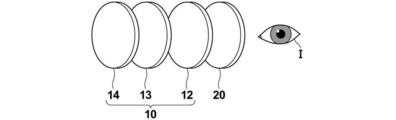
- the lens unit 10 includes a first transmissive optical element 12, a second transmissive optical element 13, and a third optical element 14.
- the first transmissive optical element 12, the second transmissive optical element 13, and the third optical element 14 are arranged in this order from the eye I side of the wearer. That is, the first transmissive optical element 12 is arranged closer to the wearer than the second transmissive optical element 13.
- the first transmissive optical element 12 transmits the image of the subject in the wearer's field of view and can change the refractive power.
- the refractive power of the first transmission optical element 12 is controlled according to the eyesight of the wearer. By controlling the refractive power of the first transmissive optical element 12, it is not necessary to prepare a plurality of products according to the eyesight of the wearer, and a single product can be used for a wide range of users.
- a matrix liquid crystal lens can be used as the first transmissive optical element 12.
- the matrix liquid crystal lens is divided into a plurality of regions, and is configured such that the refractive index can be changed for each divided region.
- the refractive index can be changed for each divided region in this way, a phase distribution that corrects the abnormality of the wavefront aberration of the wearer's eye can be generated, so that not only myopia and hyperopia, but also astigmatism and fraud Astigmatism can also be corrected.
- the wavefront aberration of the wearer's eye is measured in advance by a wavefront aberration sensor or the like, and a phase distribution for correcting the measured wavefront aberration is set in advance.
- the matrix liquid crystal lens for example, a liquid crystal lens having two liquid crystal layers whose orientation directions are orthogonal to each other can be used. Further, as the matrix liquid crystal lens, a liquid crystal lens having two liquid crystal layers having the same alignment direction and a half-wave plate provided between the two liquid crystal layers may be used. Further, a liquid crystal lens having a plurality of sets of the two liquid crystal layers described above may be used. Thus, by providing a plurality of sets of two liquid crystal layers, the variable range of refractive power can be increased.
- a liquid crystal lens is used as the first transmissive optical element 12.
- the present invention is not limited to this, and a liquid lens capable of changing the refractive power can also be used.
- the second transmissive optical element 13 displays an image using the image signal output from the imaging unit 3 and makes it incident on the eye I of the wearer.
- a phase modulation type computer generated hologram display element that forms a volume hologram is used as the second transmission optical element 13.
- the phase modulation type computer generated hologram display element is a spatial phase modulator in which a plurality of display pixels are arranged two-dimensionally.
- the video signal output from the imaging unit 3 is input to a computer generated hologram unit 51 of the control board unit 5 described later, and the computer generated hologram unit 51 calculates a computer generated hologram interference pattern using the input video signal. . Note that various known methods can be used for the calculation method of the computer generated hologram interference pattern.
- the computer generated hologram interference pattern calculated by the computer generated hologram unit 51 is input to the second transmission optical element 13 which is a phase modulation type computer generated hologram display element and displayed. Then, the reference light irradiation unit 4 irradiates the second transmissive optical element 13 with the reference light, thereby reproducing the wavefront of the display light from the virtual image position. As a result, the wearer can observe a reproduced image using the image captured by the imaging unit 3.
- the first camera 3a and the second camera 3b described above may be a normal monocular imaging system, and the phase modulation type computer generated hologram display element is imaged by the first camera 3a and the second camera 3b.
- the image is reproduced as a planar image at a position away from the phase modulation type computer generated hologram display element.
- the wearer views the playback video using the video captured by the right first camera 3a and the playback video using the video captured by the left second camera 3b with the right eye and the left eye, respectively.
- it is possible to view stereoscopically, and it is possible to observe a reproduction image having a depth.
- the second transmission type optical element 13 is irradiated with the three colors of reference light in a time-sharing manner, and therefore the computer generated hologram generation unit 51 uses an R component video signal.
- the R component computer generated hologram interference pattern is calculated
- the G component computer generated hologram interference pattern is calculated using the G component video signal
- the B component computer generated hologram interference pattern is calculated using the B component video signal.
- the second transmissive optical element 13 is controlled so as to display a computer generated hologram interference pattern having the same color component as that of the irradiated reference light.
- the reference light of the three colors is irradiated to the second transmissive optical element 13 in a time-sharing manner, and the computer hologram interference pattern of the three color components is sequentially displayed in synchronization therewith, thereby reproducing brighter. You can get a picture.
- the computer generated hologram interference pattern is displayed to generate a reproduced image, thereby eliminating the need for a loupe system. Therefore, it is possible to reduce the thickness as compared with the case where an image is displayed on the electronic display.
- the third optical element 14 is disposed closer to the subject side than the second transmissive optical element 13 described above, and transmits light that forms an image of the subject. It is possible to switch between the transmission mode and the shielding mode that shields the light that forms the image of the subject.
- the third optical element 14 is an electronic dimming barrier, and for example, a liquid crystal display can be used.
- the third optical element 14 is controlled to be in a shielding mode when the reproduced image G by the second transmission optical element 13 is incident on the wearer's eye I, and is shown in FIG. 3II.
- the transmission mode is controlled.
- it is desirable that the third optical element 14 is controlled to the transmission mode when the glasses 1 are powered off. Thus, the wearer can use the glasses 1 while wearing the power off.
- the glasses 1 include a control board unit 5 and a power supply unit 6.
- the control board 5 is provided on the left temple 101, but the present invention is not limited to this, and the control board 5 may be provided on the right temple 101. Further, the control board unit 5 may be configured to be detachable from the spectacle body 2.
- the power supply unit 6 is detachably attached to the tip (modern) of the left temple 101.
- the power supply unit 6 may include a non-rechargeable battery or a rechargeable battery. Further, power supplied from an external power source via a wire may be used, or a wireless power feeding method may be used.
- the spectacles 1 are in a state in which the weight in the left-right direction is balanced when the wearer wears the spectacles 1.
- the state in which the weight in the left-right direction is balanced is a state in which the left-right position of the center of gravity of the glasses 1 is located at the center in the left-right direction of the glasses 1.
- the control board unit 5 and the power supply unit 6 are provided on the left temple 101 as in the present embodiment, for example, a weight is provided inside the right temple 101 to balance the weight in the left-right direction. You may make it take. Further, in order to balance the weight in the left-right direction, the power supply unit 6 may be divided into left and right temples.
- FIG. 4 is a block diagram showing an electrical configuration of the glasses 1.
- the control board unit 5 includes a control unit 50, a computer generated hologram generation unit 51, a refractive power information acquisition unit 52, and a distance information acquisition unit 53.
- the control board unit 5 includes a CPU (Central Processing Unit) and a memory, and incorporates a control program and a computer generated hologram program that operate on an OS (Operating System) or firmware.
- the control unit 50, the computer generated hologram generating unit 51, the refractive power information acquiring unit 52, and the distance information acquiring unit 53 function by operating the control program and the computer generated hologram generating program.
- the control unit 50 controls operations of the imaging unit 3, the reference light irradiation unit 4, the lens unit 10, the power supply unit 6, and the line-of-sight detection unit 7.
- the computer generated hologram generation unit 51 generates a computer generated hologram interference pattern using the video signal output from the imaging unit 3 as described above.
- the control unit 50 causes the second transmissive optical element 13 to display the computer generated hologram interference pattern generated by the computer generated hologram generating unit 51.
- the refractive power information acquisition unit 52 acquires refractive power information of the first transmissive optical element 12. Specifically, the refractive power information acquisition unit 52 acquires refractive power information corresponding to the wearer's visual acuity, for example, depending on the wearer's eye power and the state of astigmatism, irregular astigmatism, and strabismus. Information on refractive power is acquired.
- the refractive power information acquisition unit 52 may acquire visual power information such as the power of the wearer's eyes and astigmatism, and obtain refractive power information of the first transmission optical element 12 from the visual power information.
- the refractive power information of the first transmissive optical element 12 corresponding to the visual acuity of the wearer may be directly acquired.
- the information on the wearer's visual acuity and the refractive power information of the first transmissive optical element 12 may be set and input using, for example, an input unit (not shown) provided in the glasses 1, or the refractive power information.
- the acquisition unit 52 may communicate with an external device different from the glasses 1 by wireless communication or wired communication, and may perform setting input in the external device. Examples of the external device that communicates with the refractive power information acquisition unit 52 include a computer and a portable terminal. You may make it install the exclusive application which displays the setting input reception screen of the wearer's visual acuity information and the refractive power information of the 1st transmission optical element 12 with respect to a computer and a portable terminal. Further, not only wireless communication but also refractive power information may be acquired by connecting the glasses 1 to a computer or a portable terminal using a USB (Universal Serial Bus) cable, for example.
- USB Universal Serial Bus
- the refractive power information of the first transmission optical element 12 acquired by the refractive power information acquisition unit 52 is output to the control unit 50, and the control unit 50 acquires the refractive power information and the distance acquired by the distance information acquisition unit 53. Using the information, the refractive power to be set for the first transmissive optical element 12 is determined, and the first transmissive optical element 12 is controlled.
- the distance information acquisition unit 53 acquires distance information between the wearer and the subject viewed by the wearer.
- the refractive power of the first transmission optical element 12 is controlled according to the eyesight of the wearer, so that myopia, hyperopia and astigmatism can be corrected.
- the distance information acquisition unit 53 acquires distance information between the wearer and the subject, and further adjusts the refractive power of the first transmissive optical element 12 using the distance information. Adjust the focus. Thereby, even when the wearer is presbyopia, it is possible to see an image of a subject in focus from a short distance to a long distance.
- the distance information acquisition unit 53 of the present embodiment acquires information on the wearer's line-of-sight direction detected by the line-of-sight detection unit 7, and uses the information on the line-of-sight direction to determine the principle of triangulation. To calculate the distance between the wearer and the subject.
- the line-of-sight detection unit 7 includes a first line-of-sight detection unit 7a and a second line-of-sight detection unit 7b.
- the first line-of-sight detection unit 7 a is provided on the upper side of the right rim 102
- the second line-of-sight detection unit 7 b is provided on the upper side of the left rim 102.
- the first line-of-sight detection unit 7a and the second line-of-sight detection unit 7b include an infrared light source that irradiates the wearer's eyes with infrared light, and an infrared camera that captures a reflected image from the cornea and the lens of the eye by irradiation of infrared rays I have.
- the wearer's line-of-sight direction is the front
- the position of the reflection image of the cornea matches the position of the reflection image of the lens
- the line-of-sight direction is a direction other than the front
- the reflection image of the cornea and the lens The position of the reflected image shifts.
- the first line-of-sight detection unit 7a calculates the line-of-sight direction of the right eye using the amount of deviation between the reflected image of the cornea and the reflected lens of the right eye
- the second line-of-sight detection unit 7b calculates the line-of-sight direction of the left eye using the amount of deviation between the reflection image of the cornea of the left eye and the reflection image of the crystalline lens.
- the line-of-sight directions of the right eye and the left eye calculated by the line-of-sight detection unit 7 are output to the distance information acquisition unit 53, and the distance information acquisition unit 53 is information on the line-of-sight directions of the right eye and the left eye as described above. Is used to calculate the distance between the wearer and the subject.
- the gaze direction of the wearer is detected and the distance between the wearer and the subject is calculated using the principle of triangulation, but the wearer and the subject
- the method for calculating the distance is not limited to this.
- the distance between the wearer and the subject is calculated using the contrast information or the phase difference information calculated during the autofocus control of the first camera 3a and the second camera 3b that captures the subject. It may be. Specifically, for example, by detecting the lens position of the first camera 3a or the second camera 3b when the in-focus position is detected using contrast information or phase difference information, between the wearer and the subject. The distance may be calculated.
- the first camera 3a and the second camera 3b are installed at positions separated from each other in the left-right direction of the spectacle main body 2, when the subject is close to the spectacle main body, the first camera 3a takes an image.
- the subject image captured by the second camera 3b has a large distance in the left-right direction, and the subject is far from the glasses body, the subject image captured by the first camera 3a and the second image captured by the second camera 3b
- the distance in the left-right direction is narrower than the subject image picked up by the camera 3b. Therefore, the distance between the wearer and the subject may be calculated by calculating the interval between the subject image captured by the first camera 3a and the subject image captured by the second camera 3b. Good.
- the convergence angle may be calculated using the gaze direction of the wearer's right eye and left eye, and the distance between the wearer and the subject may be calculated using the convergence angle. Note that the relationship between the convergence angle and the distance may be set in advance by a function or a table.
- the movement amount of the wearer's right eye and left eye in the vertical direction of the line of sight may be calculated, and the distance between the wearer and the subject may be calculated using the movement amount. It should be noted that the relationship between the vertical movement amount in the line-of-sight direction and the distance may be set in advance by a function or a table.
- a myoelectric sensor for measuring the myoelectric potential of the right eye and the left eye is provided for the spectacle body 2, the convergence angle is calculated using the myoelectric potential measured by the myoelectric potential sensor, and the mystery angle is used for wearing.
- the distance between the person and the subject may be calculated. It is assumed that the relationship between the myoelectric potential and the convergence angle is set in advance.
- the degree of tension of the ciliary body may be calculated by measuring the myoelectric potentials of the right eye and the left eye, and the distance between the wearer and the subject may be calculated using the degree of tension. In this case as well, the relationship between the myoelectric potential and the tension level of the ciliary body and the relationship between the tension level and the distance are set in advance.
- the glasses 1 according to the present embodiment switch between the video display mode and the glasses mode according to the brightness of the wearer's surrounding environment.
- the video display mode is a mode in which the reproduced video G by the second transmissive optical element 13 is incident on the eye I of the wearer
- the spectacles mode is an image H of the subject that has passed through the second transmissive optical element 13. In this mode, the light enters the eye I of the wearer.
- the wearer's surrounding environment is dark, by switching to the video display mode, the wearer can see a bright reproduction video G.
- the wearer's surrounding environment is bright, the wearer can use the glasses function. A clearer image H of the subject can be visually recognized.
- a power button (not shown) of the glasses 1 is pressed to turn on the glasses 1.
- information on the eyesight of the wearer is set and input using an input unit provided on the glasses 1 or a computer or a portable terminal (S10).
- Information on the wearer's visual acuity is acquired by the refractive power information acquisition unit 52, and the refractive power information acquisition unit 52 uses the information on the visual acuity of the wearer to be refracted to be set in the first transmission optical element 12. Seeking power.
- the wearer may set and input information measured by a dedicated device. Or you may make it measure using the application preset for the computer or the portable terminal.
- the control unit 50 acquires the information of the brightness of a wearer's surrounding environment using the input video signal, and performs the brightness determination of a surrounding environment (S12). Specifically, the control unit 50 sets the video display mode when the brightness of the surrounding environment is equal to or less than a preset first threshold, that is, when the surrounding environment is dark. On the other hand, when the brightness of the surrounding environment is larger than the first threshold, that is, when the surrounding environment is bright, the glasses mode is set. Note that as brightness information of the surrounding environment, statistical values such as an average value, a maximum value, a minimum value, and an intermediate value of the video signal output from the imaging unit 3 may be obtained.
- the third optical element 14 is controlled to the transmission mode (S14).
- the gaze direction of the wearer is detected by the gaze detection unit 7
- information on the gaze direction is acquired by the distance information acquisition unit 53
- the distance information acquisition unit 53 uses the information on the gaze direction to The distance to the subject in the line of sight of the wearer is acquired (S16).
- the refractive power information acquired by the refractive power information acquisition unit 52 and the distance information acquired by the distance information acquisition unit 53 are acquired by the control unit 50.
- the controller 50 adjusts the refractive power according to the visual acuity of the wearer using the distance information, controls the first transmission optical element 12, and sets the adjusted refractive power (S18).
- the refractive power of the first transmissive optical element 12 can be set to a refractive power according to the eyesight of the wearer and the presbyopia. Therefore, the wearer can use the spectacles 1 as both-distance and spectacles, and can correct astigmatism and irregular astigmatism.
- the refractive index of the second transmissive optical element 13 is controlled uniformly.
- the control unit 50 switches to the video display mode when the brightness of the surrounding environment is equal to or lower than the second threshold value set in advance, that is, when the surrounding environment becomes dark.
- the 2nd threshold value used for the brightness determination at this time is desirably smaller than the first threshold value described above. This is because when the second threshold value in S20 is the same as the first threshold value in S12, the glasses mode and the video display mode are switched due to a slight brightness difference in the surrounding environment, which is troublesome for the wearer.
- the operation of the glasses 1 in the video display mode will be described.
- the surrounding environment is determined to be dark in S20 after entering the glasses mode, and in the initial state of S12, it is determined that the brightness information of the surrounding environment is smaller than the first threshold value. Is set to the video display mode.
- the refractive power information acquired by the refractive power information acquisition unit 52 is acquired by the control unit 50.
- the control unit 50 controls the first transmission optical element 12 using the refractive power information and sets the refractive power according to the eyesight of the wearer (S22).
- the first transmissive optical element 12 is arranged closer to the wearer than the second transmissive optical element 13, so that the refractive power of the first transmissive optical element 12 is increased.
- the position of the reproduced video can be adjusted by setting according to the visual acuity of the wearer, and the wearer can clearly see the reproduced video by the second transmissive optical element 13.
- the position of the reproduced video is preferably closer to the subject than the second transmission optical element 13 when the wearer is nearsighted, and second when the wearer is hyperopic or presbyopia.
- the transmissive optical element 13 is preferably closer to the wearer.
- control unit 50 controls the third optical element 14 to the shielding mode (S24). Thereby, the incidence of external light on the wearer's eyes can be blocked. Then, the imaging unit 3 captures an image of the wearer's visual field (S 26), and the video signal output from the imaging unit 3 is input to the computer generated hologram generation unit 51.
- the reference light of the three colors G (green), B (blue), and R (red) is transmitted in this order from the reference light irradiation unit 4 to the second transmissive optical element 13.
- the irradiation of the three colors of reference light is controlled as follows. First, the wavelength number w indicating the wavelength (color) of the reference light is set to zero (S28). In the present embodiment, the wavelength number w of the G reference light is set to “1”, the wavelength number w of the B reference light is set to “2”, and the wavelength number of the R reference light is “3”. Is set to
- the wavelength number w is incremented by “1”, and the wavelength number w is set to “1”.
- the computer generated hologram unit 51 generates a computer generated hologram interference pattern of the G component using the input video signal (S32), and the second transmission optical element 13 (S34).
- the reference light having the wavelength (color) corresponding to the wavelength number is irradiated to the second transmission optical element 13. That is, the G reference light having the wavelength number “1” is irradiated to the second transmission optical element 13 (S36).
- the reproduction image of the G component is first incident on the wearer's eye.
- the computer generated hologram generating unit 51 When the wavelength number w is set to “2”, the computer generated hologram generating unit 51 generates a B component computer generated hologram interference pattern using the input video signal (S32), and the second transmissive optical element 13 (S34). At this time, the B reference light having the wavelength number w of “2” is applied to the second transmission optical element 13 (S36). Thereby, the reproduction image of the B component is incident on the wearer's eye.
- the computer generated hologram generating unit 51 When the wavelength number w is set to “3”, the computer generated hologram generating unit 51 generates an R component computer generated hologram interference pattern using the input video signal (S32), and the second transmission optical element. 13 (S34). At this time, the R reference light having the wavelength number w of “3” is applied to the second transmission optical element 13 (S36). As a result, the reproduced image of the R component is incident on the wearer's eye.
- the G component, the B component, and Reproduced video can be made incident according to the order of the R component.
- Reproduction video is made incident in this order because the G component has the highest visual sensitivity among the three color components, and it is preferable to make it enter preferentially in order to use the time lag, and the eye is adapted to dark adaptation. This is because it is preferable to make the second incident since the visibility of the B component is high.
- the processes from S28 to S38 are repeated.
- the brightness of the surrounding environment is determined at a predetermined interval (S40).
- a preset third threshold value that is, when the surrounding environment becomes bright
- the control unit 50 switches to the glasses mode.
- the 3rd threshold value used for the brightness determination at this time is desirably larger than the first threshold value described above. This is because when the third threshold value in S40 is the same as the first threshold value in S12, the glasses mode and the video display mode are switched due to a slight brightness difference in the surrounding environment, which is troublesome for the wearer.
- the control unit 50 may set the intermediate mode.
- the reproduced image is displayed by the second transmissive optical element 13 and the subject image transmitted through the first transmissive optical element 12 and the second transmissive optical element 13 is displayed on the wearer. It may be made to enter into the eyes.
- the transmittance of the third optical element 14 with respect to the light forming the subject image may be changed continuously or stepwise.
- the video display mode and the glasses mode may be switched using only the first threshold without setting the second threshold and the third threshold.
- the result of the brightness determination is used to switch between the glasses mode and the video display mode.
- the first threshold value used for the brightness determination is It may be changed between when the person is in the room and when the wearer is outside. Specifically, for example, when the wearer is indoors, the glasses mode and the video display mode may be switched depending on whether the brightness is suitable for VDT (Visual Display Terminals) work. Generally, in order to perform VDT work, it is desirable that the surrounding environment has a brightness of 300 to 500 lux or more. Therefore, when the wearer is in the room, it is desirable to set the first threshold value used for the brightness determination to a value corresponding to 300 to 500 lux.
- the second and third threshold values may be set as appropriate according to the first threshold value.
- the glasses mode and the video display mode may be switched depending on whether the brightness is sufficient for walking safely.
- the brightness of the moonlight is necessary, and it is desirable that the surrounding environment has a brightness of 0.1 to 1 lux or more. Therefore, when the wearer is outside, it is desirable to set the first threshold value used for the brightness determination to a value corresponding to 0.1 to 1 lux.
- the wearer is an elderly person, it is desirable to have the brightness of a streetlight in order to walk outside safely, and it is desirable that the surrounding environment has a brightness of 50 to 200 lux or more. Therefore, when the wearer is an elderly person and is outside, it is desirable to set a value corresponding to 50 to 200 as the first threshold value used for the brightness determination.
- the switching of the first to third threshold values described above may be performed using, for example, an input unit (not shown) provided in the glasses 1, or a computer or portable terminal that communicates with the glasses 1 may be switched. You may make it switch using. Alternatively, it is possible to automatically determine whether the wearer is in the room or outside using the video signal imaged by the imaging unit 3, and to switch the first to third thresholds according to the determination result. .
- a fixed focal length lens 20 may be provided on the wearer side of the lens unit 10, and a plurality of fixed focal length lenses having different refractive powers may be provided. It is desirable that 20 be configured to be interchangeable with the eyeglass body 2.
- the fixed focal length lens 20 matches the visual acuity of the wearer, the variable width of the refractive power of the first transmissive optical element 12 and the variable width of the position of the reproduced image by the second transmissive optical element 13 are suppressed. And the burden on these optical elements can be reduced.
- various well-known structures can be used for the mechanical structure that allows the fixed focal length lens 20 to be replaced.
- the glasses 1 of the above embodiment it is desirable to uniformly control the refractive indexes of the first transmissive optical element 12 and the second transmissive optical element 13 when the power is turned off. As a result, it is possible to prevent darkness or scattering from occurring when the power is turned off.
- the imaging unit 3 has a scaling function. If necessary, it is possible to obtain a wider-angle image and an enlarged image than normal vision.
- a scaling function is realized by the imaging unit 3 having a zoom lens or a digital zoom function.
- the change of the magnification of the imaging unit 3 may be set and input using an input unit provided in the glasses 1, or may be set and input in a computer and a portable terminal that communicate with the glasses 1.
- the third optical element 14 is controlled to the shielding mode.
- the present invention is not limited to this, and a part of the light that forms the image of the subject is used. You may make it control to the semi-transmission mode which shields.
- the phase modulation type computer generated hologram display element is used as the second transmission type optical element 13, but the present invention is not limited to this, and as shown in FIG.
- the mold optical element 15 a free-form surface semi-transmissive mirror or a holographic optical element may be used. Then, the image picked up by the image pickup unit 3 is displayed on the display element 16, and the image displayed on the display element 16 is reflected by the second transmission optical element 15 in the direction of the eye I of the wearer. You may make it show a virtual image.
- the free-form semi-transparent mirror and the holographic optical element are capable of transmitting an image of a subject that has been transmitted through the third optical element 14 and are capable of reflecting an image displayed on the display element 16.
- mass production is easy.
- a holographic optical element by providing wavelength selectivity, both the reflectance of the display wavelength of the image displayed on the display element 16 and the transmittance of light other than the display wavelength are 50% or more. And can be efficient.
- the display element 16 may be provided, for example, on the rim 102 of the spectacle body 2, but is preferably provided on the lower sides of the left and right rims 102. As a result, the wearer can be prevented from entering the field of view and can be disposed between the wearer's face and the rim 102 so that it does not get in the way.
- the display element for example, a liquid crystal display, an organic EL (Electro Luminescence) display, or the like can be used.
- the configuration in which the image displayed on the display element is reflected by the second transmission optical element and is incident on the eye I of the wearer is not limited to the configuration shown in FIG.
- the second transmissive optical element 17 is provided with a transflective portion 17b made of a free-form semi-transmissive mirror or a holographic optical element at the center of the light guide plate 17a. May be. Then, the image displayed on the display element 19 is made incident on the light guide plate 17a through the lens 18, and the image guided by the light guide plate 17a is reflected by the transflective portion 17b and made incident on the eye I of the wearer. You may do it.
- the refractive power information acquired by the refractive power information acquisition unit 52 is acquired by the control unit 50.
- the control unit 50 controls the first transmission optical element 12 using the refractive power information and sets the refractive power according to the eyesight of the wearer (S60).
- control unit 50 controls the third optical element 14 to the shielding mode (S62). Thereby, the incidence of external light on the wearer's eyes can be blocked.
- the imaging unit 3 captures an image of the wearer's visual field (S64), and the video signal output from the imaging unit 3 is input to the display elements 16 and 19 to display the video (S66).
- the images displayed on the display elements 16 and 19 are reflected by the second transmissive optical elements 15 and 17 and enter the eyes of the wearer.
- the brightness of the surrounding environment is determined at a preset interval (S68). Then, when the brightness of the surrounding environment becomes larger than a preset third threshold value, that is, when the surrounding environment becomes bright, the control unit 50 switches to the glasses mode.
- the 3rd threshold value used for the brightness determination at this time is the same as that of the said embodiment.
- the first transmissive optical element 12 may be omitted by causing the second transmissive optical element 13 in the above embodiment to function as the first transmissive optical element 12.
- the matrix liquid crystal lens may be made to function by controlling the refractive index of each pixel of the phase modulation type computer generated hologram display element as the second transmission type optical element 13.
- FIG. 11 is a flowchart showing the flow of the operation of the glasses 1 when the second transmissive optical element 13 functions as the first transmissive optical element as described above. As shown in FIG. 11, the operation in the eyeglass mode in S10, S12 and S14 to S20 is the same as that in the above embodiment, and the operation in the video display mode shown in S42 to S56 is different from that in the above embodiment.
- a thin hologram element that forms a two-dimensional refractive index distribution may be used as the second transmission optical element 13 of the above embodiment.
- the thin hologram element is composed of a two-dimensional matrix liquid crystal.
- a thin hologram element can have a simpler structure than a volume hologram.
- the thin hologram element functions as a transmission hologram, it is desirable to provide a wavelength selective reflecting member on the subject side surface of the thin hologram element in order to sufficiently reflect the above-described reference light.
- the wavelength selective reflection member reflects the reference light and transmits light having a wavelength other than the reference light. Note that since the bandwidths of the G, B, and R reference lights are narrow, the wavelength-selective reflecting member can transmit the image of the subject by transmitting light having a wavelength other than the reference light.
- the second transmission type optical element 13 is irradiated with G, B, and R reference light in a time-sharing manner.
- the second transmission type optical element 13 is irradiated with G. , B and R reference light may be irradiated simultaneously.
- the second transmissive optical element 13 displays a computer generated hologram interference pattern that simulates multiple exposure of three types of G, B, and R reference lights.
- a known method can be used to generate a computer generated hologram interference pattern simulating multiple exposure (for example, Production Research, Vol. 18, No. 9, 1966.09.01, pp. 237-242, “Commercial Films”). (See Holographic by).
- the frame rate can be increased by simultaneously irradiating G, B and R reference beams.
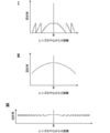
- the first transmissive optical element 12 is formed into a lens around a place corresponding to the line of sight.
- a Fresnel type refractive index distribution and to function as a diffractive lens are desirable to use.
- a refractive index distribution that is continuous from the center of the lens may be used so as to function as a refractive lens.
- a refractive index distribution as shown in FIG. 12III may be used to function as a Fresnel lens.
- the refractive power of the first transmission optical element 12 is further controlled using the information on the visual acuity of the wearer and the distance between the wearer and the subject. Is done.
- the brightness information of the surrounding environment of the wearer is acquired using the video signal output from the imaging unit 3.
- a brightness detection unit may be provided.
- a PD PhotoPDDetector
- a photodiode may be used as the brightness detection unit.
- the video using the video signal output from the imaging unit 3 is displayed or reflected by the second transmissive optical element.
- the video output from the imaging unit 3 is not necessarily used.
- the control unit 50 communicates with an external device different from the glasses 1 to acquire a video signal output from the external device, and transmits the video using the video signal to the second transmission. It may be displayed or reflected by a mold optical element.
- a wearing state detection unit that detects the wearing state of the glasses 1 to the wearer is provided, and the power is automatically turned on when the wearer wears the glasses 1, so that the wearer May turn off the power automatically when the eyeglasses 1 are removed.
- the wearing state detection unit can detect the wearing state of the eyeglass body 2 to the wearer, for example, by detecting the open / closed state of the temple 101 using an open / close sensor.
- the open / close sensor for example, a limit switch that is turned on when the temple 101 is closed and turned off when the temple 101 is opened can be used.
- the method of detecting the wearing state of the spectacle body 2 to the wearer is not limited to the above-described method. You may make it detect the mounting state to the wearer of the spectacles main body 2 by detecting contact
- a sensor for example, a pressure sensor that outputs a signal corresponding to pressure can be used.
Landscapes
- Physics & Mathematics (AREA)
- General Physics & Mathematics (AREA)
- Optics & Photonics (AREA)
- Health & Medical Sciences (AREA)
- Life Sciences & Earth Sciences (AREA)
- Nonlinear Science (AREA)
- Astronomy & Astrophysics (AREA)
- Chemical & Material Sciences (AREA)
- Crystallography & Structural Chemistry (AREA)
- Ophthalmology & Optometry (AREA)
- Biophysics (AREA)
- Engineering & Computer Science (AREA)
- Biomedical Technology (AREA)
- Heart & Thoracic Surgery (AREA)
- Medical Informatics (AREA)
- Molecular Biology (AREA)
- Surgery (AREA)
- Animal Behavior & Ethology (AREA)
- General Health & Medical Sciences (AREA)
- Public Health (AREA)
- Veterinary Medicine (AREA)
- Liquid Crystal (AREA)
Abstract
映像表示機能と眼鏡機能とを有し、装着者の視力などに応じて屈折力を変更することができ、さらに映像表示機能によって再生される映像の見え方を矯正可能な映像表示機能付き眼鏡を提供する。 被写体の像を透過し、かつ屈折力を変更可能な第1の透過型光学素子12と、映像信号を用いた映像を表示または反射し、かつ被写体の像を透過する第2の透過型光学素子13とを備え、第2の透過型光学素子12によって映像を表示または反射させて眼鏡本体の装着者の眼に入射させる映像表示モードと、第1の透過型光学素子および第2の透過型光学素子を透過した被写体の像を装着者の眼に入射させる眼鏡モードとを切り替え可能にし、第1の透過型光学素子12を第2の透過型光学素子13よりも装着者側に配置する。
Description
本発明は、眼鏡レンズに表示または投影された映像を装着者に見せる映像表示機能付き眼鏡に関するものである。
従来、頭部に装着する透過型の眼鏡型表示装置が種々提案されている。たとえば特許文献1においては、装着者の前方の景色を撮像部によって撮像し、その映像を眼鏡型の表示部に表示させる眼鏡型表示装置が提案されている。
特許文献1の眼鏡型表示装置においては、表示部に表示される映像を拡大表示させたり、また、表示部をスルー状態にしたりすることが提案されている。
また、特許文献2においては、表示部に表示された映像を板状部材によって導光し、板状部材内に設けられたホログラム素子によって装着者の眼に向けて映像を反射させる眼鏡型表示装置が提案されている。特許文献2においては、板状部材に光学的パワーを持たせることが提案されている。
しかしながら、特許文献1に記載の眼鏡型表示装置のスルー状態は、単に表示部を透過状態に制御しているだけであるので、たとえば装着者が近視や遠視などの場合には、前方の景色を明瞭に視認することができない。
また、特許文献2においては、上述したように板状部材に光学的パワーを持たせることが提案されているが、この光学的パワーは固定であるため、装着者の視力に応じて変更することはできない。また、特許文献2の眼鏡型表示装置の場合、装着者は、前方の景色を鮮明に見ることができたとしても、ホログラム素子によって形成される虚像の見え方を矯正することはできない。
本発明は、上記の問題に鑑み、映像表示機能と眼鏡機能との双方を有し、かつ装着者の視力などに応じて屈折力を変更することができ、さらに映像表示機能によって再生される映像の見え方を矯正することができる映像表示機能付き眼鏡を提供することを目的とする。
本発明の第1の映像表示機能付き眼鏡は、眼鏡本体と、被写体の像を透過し、かつ屈折力を変更可能な第1の透過型光学素子と、映像信号を用いた映像を表示または反射し、かつ被写体の像を透過する第2の透過型光学素子と、第2の透過型光学素子によって映像を表示または反射させて眼鏡本体の装着者の眼に入射させる映像表示モードと、第1の透過型光学素子および第2の透過型光学素子を透過した被写体の像を装着者の眼に入射させる眼鏡モードとを切り替え可能に制御する制御部とを備え、第1の透過型光学素子が、第2の透過型光学素子よりも装着者側に配置されている。
また、上記本発明の第1の映像表示機能付き眼鏡においては、第1の透過型光学素子として、液晶レンズを用いることができる。
また、上記本発明の第1の映像表示機能付き眼鏡において、液晶レンズは、複数の分割領域を有し、分割領域毎に屈折率を変更可能とすることができる。
また、上記本発明の第1の映像表示機能付き眼鏡においては、第2の透過型光学素子よりも被写体側に、被写体の像を形成する光を透過させる透過モードと被写体の像を形成する光を遮蔽する遮蔽モードとを切り替え可能な第3の光学素子を有し、制御部は、映像表示モードの場合には、第3の光学素子を遮蔽モードに制御し、眼鏡モードの場合には、第3の光学素子を透過モードに制御することができる。
また、上記本発明の第1の映像表示機能付き眼鏡においては、第2の透過型光学素子よりも被写体側に、被写体の像を形成する光を透過させる透過モードと被写体の像を形成する光の一部を遮蔽する半透過モードとを切り替え可能な第3の光学素子を有し、制御部は、映像表示モードの場合には、第3の光学素子を半透過モードに制御し、眼鏡モードの場合には、第3の光学素子を透過モードに制御することができる。
また、上記本発明の第1の映像表示機能付き眼鏡において、制御部は、電源がオフされている場合には、第3の光学素子を透過モードに制御することができる。
また、上記本発明の第1の映像表示機能付き眼鏡においては、第1の透過型光学素子の屈折力情報を取得する屈折力情報取得部を備え、制御部は、屈折力情報取得部によって取得された屈折力情報を用いて第1の透過型光学素子の屈折力を制御することができる。
また、上記本発明の第1の映像表示機能付き眼鏡においては、第1の透過型光学素子の装着者側に、屈折力の異なる複数の固定焦点距離レンズを交換可能に構成することができる。
また、上記本発明の第1の映像表示機能付き眼鏡においては、第2の透過型光学素子として、位相変調型計算機ホログラム表示素子を用いることができる。
また、上記本発明の第1の映像表示機能付き眼鏡において、位相変調型計算機ホログラム表示素子は、複数の表示画素を有することができる。
また、上記本発明の第1の映像表示機能付き眼鏡において、位相変調型計算機ホログラム表示素子は、映像信号を用いた計算機ホログラム干渉パターンを表示することができる。
また、上記本発明の第1の映像表示機能付き眼鏡において、位相変調型計算機ホログラム表示素子は、位相変調型計算機ホログラム表示素子から離れた位置に映像を平面像として再生することができる。
また、上記本発明の第1の映像表示機能付き眼鏡においては、位相変調型計算機ホログラム表示素子に対して参照光を照射する参照光照射部を設けることができる。
また、上記本発明の第1の映像表示機能付き眼鏡においては、位相変調型計算機ホログラム表示素子として、薄型ホログラム素子を用いることができる。
また、上記本発明の第1の映像表示機能付き眼鏡においては、薄型ホログラム素子の被写体側に波長選択性反射部材を設けることができ、波長選択性反射部材は、参照光を反射し、参照光以外の波長の光を透過することができる。
また、上記本発明の第1の映像表示機能付き眼鏡において、参照光照射部は、位相変調型計算機ホログラム表示素子に対して、互いに波長が異なる3種類の参照光を時分割に照射し、位相変調型計算機ホログラム表示素子は、各波長の参照光に対応する計算機ホログラム干渉パターンを時分割に表示することができる。
また、上記本発明の第1の映像表示機能付き眼鏡において、参照光照射部は、位相変調型計算機ホログラム表示素子に対して、互いに波長が異なる3種類の参照光を同時に照射し、位相変調型計算機ホログラム表示素子は、3種類の参照光の多重露光をシミュレートした計算機ホログラム干渉パターンを表示することができる。
また、上記本発明の第1の映像表示機能付き眼鏡において、制御部は、眼鏡モードの場合には、参照光照射部を消灯し、映像表示モードの場合には、参照光照射部を点灯することができる。
また、上記本発明の第1の映像表示機能付き眼鏡において、参照光照射部は、直線偏光された参照光を位相変調型計算機ホログラム表示素子に対して照射することができる。
また、上記本発明の第1の映像表示機能付き眼鏡において、制御部は、眼鏡モードの場合には、第2の透過型光学素子の屈折率を均一に制御することができる。
また、上記本発明の第1の映像表示機能付き眼鏡においては、装着者と被写体との間の距離情報を取得する距離情報取得部を備え、制御部は、距離情報取得部によって取得された距離情報を用いて、第1の透過型光学素子の屈折力を制御することができる。
また、上記本発明の第1の映像表示機能付き眼鏡において、制御部は、電源がオフされている場合には、第1の透過型光学素子および第2の透過型光学素子の屈折率を均一に制御することができる。
また、上記本発明の第1の映像表示機能付き眼鏡において、第1の透過型光学素子は、配向方向が直交する2層の液晶層を有することができる。
また、上記本発明の第1の映像表示機能付き眼鏡において、第1の透過型光学素子は、配向方向が同一の2層の液晶層を有し、2層の液晶層の間に1/2波長板を備えたものとできる。
また、上記本発明の第1の映像表示機能付き眼鏡において、第1の透過型光学素子は、2層の液晶層の組を複数有するものとできる。
また、上記本発明の第1の映像表示機能付き眼鏡において、制御部は、第1の透過型光学素子を制御して、眼の波面収差の異常を補正する位相分布を生成することができる。
また、上記本発明の第1の映像表示機能付き眼鏡において、制御部は、装着者の周辺環境の明るさの情報を取得し、明るさが予め設定された第1の閾値以下である場合に、眼鏡モードから映像表示モードに切り替えることができる。
また、上記本発明の第1の映像表示機能付き眼鏡において、制御部が、明るさが第1の閾値よりも大きく眼鏡モードに設定された場合、明るさが、第1の閾値よりも小さい第2の閾値以下である場合に、眼鏡モードから映像表示モードに切り替え、明るさが第1の閾値以下であり映像表示モードに設定された場合、明るさが、第1の閾値よりも大きい第3の閾値より大きくなった場合に、映像表示モードから眼鏡モードに切り替えることができる。
また、上記本発明の第1の映像表示機能付き眼鏡において、制御部は、明るさが第1の閾値と第2の閾値との間である場合および明るさが第1の閾値と第3の閾値との間である場合には、被写体の像を形成する光に対する第3の光学素子の透過率を連続的または段階的に変更することができる。
また、上記本発明の第1の映像表示機能付き眼鏡において、制御部は、明るさが第1の閾値と第2の閾値との間である場合および明るさが第1の閾値と第3の閾値との間である場合には、第2の透過型光学素子に映像を表示させ、かつ第1の透過型光学素子および第2の透過型光学素子を透過した被写体の像を装着者の眼に入射させる中間モードに制御することができる。
また、上記本発明の第1の映像表示機能付き眼鏡においては、被写体を撮像して映像信号を出力する撮像部を備えることができる。
また、上記本発明の第1の映像表示機能付き眼鏡において、撮像部は、変倍機能を有することができる。
本発明の第2の映像表示機能付き眼鏡は、眼鏡本体と、被写体の像を透過し、かつ屈折力を変更可能な透過型光学素子であって、映像信号を用いた映像を表示する透過型光学素子と、透過型光学素子によって映像を表示させて眼鏡本体の装着者の眼に入射させる映像表示モードと、透過型光学素子を透過した被写体の像を装着者の眼に入射させる眼鏡モードとを切り替え可能に制御する制御部とを備える。
本発明の第1の映像表示機能付き眼鏡によれば、被写体の像を透過し、かつ屈折力を変更可能な第1の透過型光学素子と、映像信号を用いた映像を表示または反射し、かつ被写体の像を透過する第2の透過型光学素子とを備える。そして、第2の透過型光学素子によって映像を表示または反射させて眼鏡本体の装着者の眼に入射させる映像表示モードと、第1の透過型光学素子および第2の透過型光学素子を透過した被写体の像を装着者の眼に入射させる眼鏡モードとを切り替え可能としたので、映像表示機能と眼鏡機能との双方を有し、かつ装着者の視力などに応じて屈折力を変更することができる。
さらに第1の透過型光学素子が、第2の透過型光学素子よりも装着者側に配置されているので、映像表示機能によって再生される映像の見え方も矯正することができる。
本発明の第2の映像表示機能付き眼鏡によれば、眼鏡本体と、被写体の像を透過し、かつ屈折力を変更可能な透過型光学素子であって、映像信号を用いた映像を表示する透過型光学素子とを備える。そして、透過型光学素子によって映像を表示させて眼鏡本体の装着者の眼に入射させる映像表示モードと、透過型光学素子を透過した被写体の像を装着者の眼に入射させる眼鏡モードとを切り替え可能にしたので、映像表示機能と眼鏡機能との双方を有し、かつ装着者の視力などに応じて屈折力を変更することができる。
以下、本発明の映像表示機能付き眼鏡1の一実施形態について、図面を参照しながら詳細に説明する。図1は、本実施形態の映像表示機能付き眼鏡1の概略構成を示す斜視図である。なお、本明細書において、“前”、“後”、“左”、“右”、“上”、及び“下”とは、映像表示機能付き眼鏡を装着者の頭部に装着した状態で、その装着者から見た場合の“前”、“後”、“左”、“右”、“上”、及び“下の各方向を指すものとする。
本実施形態の映像表示機能付き眼鏡1(以下、単に眼鏡1という)は、映像表示機能を有するものであり、眼鏡1の装着者の視野内を撮像部によって撮影した映像を眼鏡1のレンズ部に表示または投影し、レンズ部によって表示または反射された光を装着者の眼に入射させることによって装着者に虚像を見せるものである。さらに、眼鏡1は、眼鏡機能を有するものであり、装着者の視力に合わせて視度調整可能に構成されたものである。
本実施形態の眼鏡1は、具体的には、図1に示すように、装着者の頭部に装着される眼鏡本体2と、撮像部3と、参照光照射部4と、制御基板部5と、電源部6と、視線検出部7とを備えている。
眼鏡本体2は、フレーム11と、フレーム11に取り付けられた2つのレンズ部10とを備えている。フレーム11は、装着者の耳に掛けられるテンプル101と、ヒンジを介してテンプル101に接続されるリム102と、左右のリム102の間を接続するブリッジ103と、鼻パッド104とから構成されている。
そして、眼鏡本体2に対して撮像部3が設けられている。撮像部3は例えば、CCD(Charge Coupled Device)イメージセンサやCMOS(Complementary Metal Oxide Semiconductor)イメージセンサ、及び光学レンズ等により構成されている。撮像部3は、右側のテンプル101上に設けられた第1のカメラ3aと、左側のテンプル101上に設けられた第2のカメラ3bとを備えている。第1のカメラ3aおよび第2のカメラ3bは、眼鏡1の装着者の視野に含まれる被写体を撮影して映像信号を出力するものである。
なお、第1のカメラ3aおよび第2のカメラ3bは、テンプル101上に限らず、左右のリム102上にそれぞれ設けるようにしてもよい。また、眼鏡本体2のリム102およびテンプル101に埋め込んで一体化するようにしてもよい。また、第1のカメラ3aおよび第2のカメラ3bは、眼鏡本体2に対して着脱可能に構成するようにしてもよい。
また、眼鏡本体2の左右のリム102の上辺には参照光照射部4が設けられている。参照光照射部4は、右側のリム102の上辺に設けられた第1の光源部4aと、左側のリム102の上辺に設けられた第2の光源部4bとを備えている。第1の光源部4aおよび第2の光源部4bは、レンズ部10内に設けられた、後述する第2の透過型光学素子13に対して参照光を照射するものである。第1の光源部4aおよび第2の光源部4bによって位相変調型計算機ホログラム表示素子からなる第2の透過型光学素子13へ参照光を照射することよって、撮像部3によって撮像された映像を用いた再生映像が第2の透過型光学素子13によって形成され、装着者の眼に入射される。
より具体的には、本実施形態の第1の光源部4aおよび第2の光源部4bは、G(緑)、B(青)およびR(赤)の3色の参照光を、第2の透過型光学素子13に対して時分割に順次照射するものである。第1の光源部4aおよび第2の光源部4bは、たとえば赤色LED(light emitting diode)、緑色LEDおよび青色LEDなどの半導体発光素子を備えたものであるが、光源としてはこれに限らない。なお、参照光照射部4は、後述する眼鏡モードの場合には、参照光を消灯し、映像表示モードの場合に、点灯するものである。
眼鏡モードの場合に参照光を消灯することによって余分な散乱光の発生および電力の消費を防止することができる。
眼鏡モードの場合に参照光を消灯することによって余分な散乱光の発生および電力の消費を防止することができる。
また、参照光は直線偏光された光とすることが望ましい。これにより第2の透過型光学素子13の層構成を簡略化することができ、たとえば1層により構成することができる。
図2は、左右のレンズ部10の具体的な構成を示す図である。レンズ部10は、図2に示すように、第1の透過型光学素子12と、第2の透過型光学素子13と、第3の光学素子14とを備えている。第1の透過型光学素子12、第2の透過型光学素子13および第3の光学素子14は、装着者の眼I側からこの順に配置されている。すなわち、第1の透過型光学素子12は、第2の透過型光学素子13よりも装着者側に配置されている。
第1の透過型光学素子12は、装着者の視野内の被写体の像を透過し、かつ屈折力を変更可能なものである。第1の透過型光学素子12の屈折力は、装着者の視力に応じて制御される。第1の透過型光学素子12の屈折力を制御することによって、装着者の視力に応じて複数の商品を準備する必要がなく、単一の製品により幅広いユーザに対応できる。
第1の透過型光学素子12としては、たとえばマトリクス液晶レンズを用いることができる。マトリクス液晶レンズは、複数の領域に分割されたものであり、分割領域毎に屈折率を変更可能に構成されたものである。
このように分割領域毎に屈折率を変更可能に構成することによって、装着者の眼の波面収差の異常を補正する位相分布を生成することができるので、近視や遠視だけでなく、乱視および不正乱視も矯正することができる。なお、装着者の眼の波面収差については、波面収差センサなどによって予め計測されており、その計測された波面収差を補正する位相分布が予め設定されているものとする。
マトリクス液晶レンズとしては、たとえば配向方向が直交する2層の液晶層を有する液晶レンズを用いることができる。また、マトリクス液晶レンズとしては、配向方向が同一の2層の液晶層を有し、その2層の液晶層の間に1/2波長板が設けられた液晶レンズを用いるようにしてもよい。また、上述した2層の液晶層の組を複数有する液晶レンズを用いるようにしてもよい。このように2層の液晶層の組を複数設けることによって屈折力の可変幅を増大させることができる。
なお、本実施形態においては、第1の透過型光学素子12として液晶レンズを用いるようにしたが、これに限らず、屈折力を変更可能な液体レンズなどを用いることもできる。
第2の透過型光学素子13は、撮像部3から出力された映像信号を用いた映像を表示させ、装着者の眼Iに入射させるものである。本実施形態においては、第2の透過型光学素子13として、体積型ホログラムを形成する位相変調型計算機ホログラム表示素子を用いる。位相変調型計算機ホログラム表示素子は、空間位相変調器であり、複数の表示画素が2次元状に配列されたものである。撮像部3から出力された映像信号は、後述する制御基板部5の計算機ホログラム生成部51に入力され、計算機ホログラム生成部51は、入力された映像信号を用いて、計算機ホログラム干渉パターンを演算する。なお、計算機ホログラム干渉パターンの演算方法については、種々の公知な手法を用いることができる。
計算機ホログラム生成部51によって演算された計算機ホログラム干渉パターンは、位相変調型計算機ホログラム表示素子である第2の透過型光学素子13に入力されて表示される。そして、参照光照射部4によって第2の透過型光学素子13に対して参照光が照射されることによって、仮想的な画像位置からの表示光の波面が再現される。この結果、装着者は、撮像部3によって撮像された映像を用いた再生映像を観察することができる。
なお、従来、位相変調型計算機ホログラム表示素子によって3次元像を再生することは知られているが、本実施形態においては、3次元像を再生する必要はなく、単に奥行きのある平面像を再生すればよい。したがって、上述した第1のカメラ3aおよび第2のカメラ3bとしては、通常の単眼撮像系でよく、位相変調型計算機ホログラム表示素子は、第1のカメラ3aおよび第2のカメラ3bによって撮像された映像を、位相変調型計算機ホログラム表示素子から離れた位置に平面像として再生する。これにより再生映像をリアルタイムに生成する計算量を大幅に少なくできる。
装着者は、右側の第1のカメラ3aによって撮像された映像を用いた再生映像と、左側の第2のカメラ3bによって撮像された映像を用いた再生映像とをそれぞれ右眼と左眼で見ることに立体視することができ、奥行きのある再生映像を観察することができる。
また、本実施形態においては、上述したように第2の透過型光学素子13に対して3色の参照光を時分割に照射するので、計算機ホログラム生成部51は、R成分の映像信号を用いてR成分の計算機ホログラム干渉パターンを演算し、G成分の映像信号を用いてG成分の計算機ホログラム干渉パターンを演算し、B成分の映像信号を用いてB成分の計算機ホログラム干渉パターンを演算する。そして、第2の透過型光学素子13は、照射された参照光の色と同じ色成分の計算機ホログラム干渉パターンを表示するように制御される。このように3色の参照光を第2の透過型光学素子13に対して時分割に照射し、それに同期させて3色の色成分の計算機ホログラム干渉パターンを順次表示させることによって、より明るい再生映像を得ることができる。
本実施形態においては、上述したように計算機ホログラム干渉パターンを表示させて再生映像を生成することにより、ルーペ系が不要となる。そのため、電子ディスプレイに映像を表示させる場合と較べて薄型化を図ることができる。
次に、第3の光学素子14は、図2に示すように、上述した第2の透過型光学素子13よりも被写体側に配置されたものであり、被写体の像を形成する光を透過させる透過モードと、被写体の像を形成する光を遮蔽する遮蔽モードとを切り替え可能なものである。第3の光学素子14は、電子式調光バリアであり、たとえば液晶ディスプレイを用いることができる。第3の光学素子14は、図3Iに示すように、第2の透過型光学素子13による再生映像Gを装着者の眼Iに入射させる場合には、遮蔽モードに制御され、図3IIに示すように、第2の透過型光学素子13を透過した被写体の像Hを装着者の眼Iに入射させる場合には、透過モードに制御されるものである。また、第3の光学素子14は、眼鏡1の電源がオフされている場合には、透過モードに制御することが望ましい。これにより装着者は電源オフ時も眼鏡1を装着したまま使用することができる。
図1に戻り、眼鏡1は、制御基板部5および電源部6を備えている。本実施形態においては、制御基板部5を左側のテンプル101に設けるようにしたが、これに限らず、右側のテンプル101に設けるようにしてもよい。また、制御基板部5を、眼鏡本体2に対して着脱可能に構成するようにしてもよい。
電源部6は、左側のテンプル101の先端(モダン)に着脱可能に取り付けられるものである。電源部6は、非充電式の電池が内蔵されたものでもよいし、充電式の電池が内蔵されたものでもよい。また、有線を介して外部電源から電力の供給を受けるものでもよいし、無線給電方式のものでもよい。
また、眼鏡1は、装着者が眼鏡1をかけたときに左右方向の重量のバランスがとれた状態であることが望ましい。左右方向の重量のバランスがとれた状態とは、眼鏡1の重心の左右方向の位置が、眼鏡1の左右方向の中心に位置する状態である。
したがって、たとえば本実施形態のように左側のテンプル101に制御基板部5および電源部6を設ける場合には、たとえば右側のテンプル101の内部に重りを設けるなどして、左右方向の重量のバランスをとるようにしてもよい。また、左右方向の重量のバランスをとるために、電源部6を左右のテンプルに分割して設けるようにしてもよい。
図4は、眼鏡1の電気的な構成を示すブロック図である。図4に示すように、制御基板部5は、制御部50と、計算機ホログラム生成部51と、屈折力情報取得部52と、距離情報取得部53とを備えている。
制御基板部5は、CPU(Central Processing Unit)およびメモリなどを備えたものであり、OS(Operating System)またはファームウェア上において動作する制御プログラムおよび計算機ホログラム生成プログラムなどが組み込まれたものである。そして、この制御プログラムおよび計算機ホログラム生成プログラムが動作することによって、制御部50、計算機ホログラム生成部51、屈折力情報取得部52および距離情報取得部53が機能する。
制御部50は、撮像部3、参照光照射部4、レンズ部10、電源部6および視線検出部7の動作を制御するものである。
計算機ホログラム生成部51は、上述したように撮像部3から出力された映像信号を用いて、計算機ホログラム干渉パターンを生成するものである。制御部50は、計算機ホログラム生成部51によって生成された計算機ホログラム干渉パターンを第2の透過型光学素子13に表示させる。
屈折力情報取得部52は、第1の透過型光学素子12の屈折力情報を取得するものである。具体的には、屈折力情報取得部52は、装着者の視力に応じた屈折力の情報を取得するものであり、たとえば装着者の眼の度数並びに乱視、不正乱視および斜視の状態に応じた屈折力の情報を取得するものである。
屈折力情報取得部52は、装着者の眼の度数および乱視などといった視力の情報を取得し、その視力の情報から第1の透過型光学素子12の屈折力情報を求めるようにしてもよいし、装着者の視力に応じた第1の透過型光学素子12の屈折力情報を直接取得するようにしてもよい。
装着者の視力の情報および第1の透過型光学素子12の屈折力情報は、たとえば眼鏡1に設けられた入力部(図示省略)を用いて設定入力するようにしてもよいし、屈折力情報取得部52が、無線通信または有線通信によって眼鏡1とは異なる外部装置と通信し、その外部装置において設定入力するようにしてもよい。屈折力情報取得部52と通信する外部装置としては、コンピュータおよび携帯端末などがある。コンピュータおよび携帯端末に対して、装着者の視力の情報および第1の透過型光学素子12の屈折力情報の設定入力受付画面を表示させる専用アプリケーションをインストールするようにしてもよい。また、無線通信に限らず、たとえばUSB(Universal Serial Bus)ケーブルなどにより眼鏡1とコンピュータまたは携帯端末とを接続することによって、屈折力情報を取得するようにしてもよい。
屈折力情報取得部52によって取得された第1の透過型光学素子12の屈折力情報は制御部50に出力され、制御部50は、その屈折力情報と距離情報取得部53によって取得された距離情報を用いて、第1の透過型光学素子12に設定する屈折力を決定し、第1の透過型光学素子12を制御する。
距離情報取得部53は、装着者と装着者が見ている被写体との距離情報を取得するものである。本実施形態の眼鏡1においては、上述したように、装着者の視力に応じて第1の透過型光学素子12の屈折力を制御するため、近視、遠視および乱視などを矯正することが可能であるが、たとえば装着者が老眼である場合、装着者の眼の度数に応じて第1の透過型光学素子12の屈折力を調節しても不十分な場合がある。そこで、本実施形態においては、距離情報取得部53によって装着者と被写体との距離情報を取得し、その距離情報を用いて、第1の透過型光学素子12の屈折力をさらに調整することによってピント調整を行う。これにより、装着者が老眼である場合でも、近距離から遠距離までピントの合った被写体の像を見ることができる。
本実施形態の距離情報取得部53は、具体的には、視線検出部7によって検出された装着者の視線方向の情報を取得し、その視線方向の情報を用いて、三角測量法の原理を用いて、装着者と被写体との距離を算出する。
視線検出部7は、具体的には、図1に示すように、第1の視線検出部7aと第2の視線検出部7bとを備えている。第1の視線検出部7aは、右側のリム102の上辺に設けられており、第2の視線検出部7bは、左側のリム102の上辺に設けられている。第1の視線検出部7aおよび第2の視線検出部7bは、赤外線を装着者の眼に照射する赤外線光源と、赤外線の照射による眼の角膜および水晶体からの反射像を撮像する赤外線カメラとを備えている。装着者の視線方向が正面である場合には、角膜の反射像と水晶体の反射像との位置が一致するが、視線方向が正面以外の方向になった場合には、角膜の反射像と水晶体の反射像との位置がずれる。この性質を利用して、第1の視線検出部7aは、右眼の角膜の反射像と水晶体の反射像とのずれ量を用いて右眼の視線方向を算出し、第2の視線検出部7bは、左眼の角膜の反射像と水晶体の反射像とのずれ量を用いて左眼の視線方向を算出する。
そして、視線検出部7によって算出された右眼および左眼の視線方向が距離情報取得部53に出力され、距離情報取得部53は、上述したように、右眼と左眼の視線方向の情報を用いて装着者と被写体との距離を算出する。
なお、本実施形態においては、装着者の視線方向を検出し、三角測量法の原理を用いて装着者と被写体との間の距離を算出するようにしたが、装着者と被写体との間の距離の算出方法については、これに限らない。
たとえば、被写体を撮影する第1のカメラ3aおよび第2のカメラ3bのオートフォーカス制御の際に算出されたコントラスト情報または位相差情報を用いて、装着者と被写体との間の距離を算出するようにしてもよい。具体的には、たとえばコントラスト情報または位相差情報を用いて合焦位置を検出した際の第1のカメラ3aまたは第2のカメラ3bのレンズ位置を検出することによって装着者と被写体との間の距離を算出するようにしてもよい。
また、第1のカメラ3aと第2のカメラ3bとは、眼鏡本体2の左右方向に離れた位置に設置されているので、被写体が眼鏡本体に近い場合には、第1のカメラ3aによって撮像される被写体像と第2のカメラ3bによって撮像される被写体像とは左右方向の間隔が大きくなり、被写体が眼鏡本体から遠い場合には、第1のカメラ3aによって撮像される被写体像と第2のカメラ3bによって撮像される被写体像とは左右方向の間隔が狭くなる。したがって、第1のカメラ3aによって撮像される被写体像と第2のカメラ3bによって撮像される被写体像との間隔を演算することによって、装着者と被写体との間の距離を算出するようにしてもよい。
また、装着者の右眼と左眼の視線方向を用いて輻輳角を算出し、その輻輳角を用いて装着者と被写体との間の距離を算出するようにしてもよい。なお、輻輳角と上記距離との関係については、関数またはテーブルなどによって予め設定するようにすればよい。
また、装着者の右眼と左眼の視線方向の上下方向についての移動量を算出し、その移動量を用いて装着者と被写体との間の距離を算出するようにしてもよい。なお、視線方向の上下方向の移動量と上記距離との関係についても、関数またはテーブルなどによって予め設定するようにすればよい。
また、右眼と左眼の筋電位を測定する筋電位センサを眼鏡本体2に対して設け、筋電位センサによって計測された筋電位を用いて輻輳角を算出し、その輻輳角を用いて装着者と被写体との間の距離を算出するようにしてもよい。なお、筋電位と輻輳角の関係については、予め設定されているものとする。また、右眼と左眼の筋電位を測定することによって、毛様体の緊張度を算出し、その緊張度を用いて装着者と被写体との間の距離を算出するようにしてもよい。なお、この場合も、筋電位と毛様体の緊張度との関係および緊張度と上記距離との関係については、予め設定されているものとする。
次に、本実施形態の眼鏡1の一連の動作について、図5に示すフローチャートを参照しながら説明する。本実施形態の眼鏡1は、装着者の周辺環境の明るさに応じて、映像表示モードと眼鏡モードとを切り替えるものである。映像表示モードは、第2の透過型光学素子13による再生映像Gを装着者の眼Iに入射させるモードであり、眼鏡モードは、第2の透過型光学素子13を透過した被写体の像Hを装着者の眼Iに入射させるモードである。装着者の周辺環境が暗い場合には、映像表示モードに切り替えることによって、装着者は明るい再生映像Gを見ることができ、装着者の周辺環境が明るい場合には、装着者は、眼鏡機能によってより明瞭な被写体の像Hを視認することができる。
まず、眼鏡1の電源ボタン(図示省略)が押下されて眼鏡1の電源がオンされる。次に、眼鏡1に設けられた入力部またはコンピュータもしくは携帯端末などを用いて、装着者の視力の情報が設定入力される(S10)。装着者の視力の情報は、屈折力情報取得部52によって取得され、屈折力情報取得部52は、装着者の視力の情報を用いて、第1の透過型光学素子12に設定されるべき屈折力を求める。なお、視力の情報については、たとえば専用の機器により測定した情報を装着者が設定入力すればよい。または、コンピュータまたは携帯端末に予め設定されたアプリケーションを用いて計測するようにしてもよい。
次に、撮像部3による撮影が開始され、撮像部3によって取得された映像信号が制御部50に出力される。そして、制御部50は、入力された映像信号を用いて、装着者の周辺環境の明るさの情報を取得し、周辺環境の明るさ判定を行う(S12)。具体的には、制御部50は、周辺環境の明るさが予め設定された第1の閾値以下である場合には、すなわち周辺環境が暗い場合には、映像表示モードに設定する。一方、周辺環境の明るさが第1の閾値よりも大きい場合には、すなわち周辺環境が明るい場合には、眼鏡モードに設定する。なお、周辺環境の明るさ情報としては、撮像部3から出力された映像信号のたとえば平均値、最大値、最小値、および中間値などの統計値を求めるようにすればよい。
以下、眼鏡モードの場合の眼鏡1の動作について説明する。眼鏡モードに設定された場合には、まず、第3の光学素子14が透過モードに制御される(S14)。
次に、視線検出部7によって装着者の視線方向が検出され、その視線方向の情報が距離情報取得部53によって取得され、距離情報取得部53は、視線方向の情報を用いて、装着者と装着者の視線方向にある被写体との距離を取得する(S16)。
そして、屈折力情報取得部52によって取得された屈折力の情報と距離情報取得部53によって取得された距離情報とが制御部50によって取得される。制御部50は、装着者の視力に応じた屈折力を、距離情報を用いて調整し、第1の透過型光学素子12を制御して、調整後の屈折力に設定する(S18)。これにより第1の透過型光学素子12の屈折力を、装着者の視力および老眼の状態に応じた屈折力に設定することができる。そのため、装着者は、眼鏡1を遠近両用の眼鏡として用いることができ、また乱視および不正乱視の矯正も行うことができる。なお、眼鏡モードの場合には、第2の透過型光学素子13の屈折率は均一に制御される。
上記のように眼鏡モードに設定された後、予め設定された間隔で周辺環境の明るさ判定が行われる(S20)。そして、制御部50は、周辺環境の明るさが予め設定された第2の閾値以下となった場合には、すなわち周辺環境が暗くなった場合には、映像表示モードに切り替える。なお、このときの明るさ判定に用いる第2の閾値は、図6に示すように、上述した第1の閾値よりも小さいことが望ましい。S20における第2の閾値がS12における第1の閾値と同じ場合、周辺環境の僅かな明るさの違いにより眼鏡モードと映像表示モードとが切り替わってしまい装着者にとって煩わしいからである。
次に、映像表示モードの場合の眼鏡1の動作について説明する。上述したように、眼鏡モードになった後、S20において周辺環境が暗い判定された場合、およびS12の初期状態において、周辺環境の明るさの情報が第1の閾値よりも小さいと判定された場合には、映像表示モードに設定される。
映像表示モードにおいては、まず、屈折力情報取得部52において取得された屈折力の情報が制御部50によって取得される。制御部50は、屈折力情報を用いて第1の透過型光学素子12を制御して、装着者の視力に応じた屈折力に設定する(S22)。本実施形態の眼鏡1においては、第1の透過型光学素子12を第2の透過型光学素子13よりも装着者側に配置しているので、第1の透過型光学素子12の屈折力を装着者の視力に応じて設定することにより再生映像の位置を調整することができ、装着者は、第2の透過型光学素子13による再生映像を明瞭に見ることができる。なお、再生映像の位置は、装着者が近視である場合には、第2の透過型光学素子13よりも被写体側であることが好ましく、装着者が遠視または老眼である場合には、第2の透過型光学素子13よりも装着者側であることが好ましい。
次いで、制御部50は、第3の光学素子14を遮蔽モードに制御する(S24)。これにより装着者の眼に対する外光の入射を遮蔽することができる。そして、撮像部3によって装着者の視野の範囲内が撮像され(S26)、撮像部3から出力された映像信号が計算機ホログラム生成部51に入力される。
そして、制御部50の制御によって参照光照射部4から第2の透過型光学素子13に対してG(緑)、B(青)およびR(赤)の3色の参照光がこの順で時分割に照射されるが、この3色の参照光の照射は、具体的には、以下のようにして制御される。まず、参照光の波長(色)を示す波長番号wがゼロに設定される(S28)。なお、本実施形態では、Gの参照光の波長番号wが「1」に設定され、Bの参照光の波長番号wが「2」に設定され、Rの参照光の波長番号が「3」に設定されている。
そして、波長番号wが「1」インクリメントされ、波長番号wが「1」に設定される。波長番号wが「1」に設定された場合、計算機ホログラム生成部51においては、入力された映像信号を用いてG成分の計算機ホログラム干渉パターンが生成され(S32)、第2の透過型光学素子13に表示される(S34)。また、このとき波長番号に応じた波長(色)の参照光が第2の透過型光学素子13に対して照射される。すなわち、波長番号wが「1」のGの参照光が第2の透過型光学素子13に対して照射される(S36)。これにより、最初にG成分の再生映像が装着者の眼に入射される。
次いで、現在の波長番号wが「3」であるか否かが制御部50によって確認され(S38)、波長番号wが「3」でない場合には、S30に戻り、波長番号wが「1」インクリメントされ、波長番号wが「2」に設定される。
波長番号wが「2」に設定された場合、計算機ホログラム生成部51においては、入力された映像信号を用いてB成分の計算機ホログラム干渉パターンが生成され(S32)、第2の透過型光学素子13に表示される(S34)。また、このとき波長番号wが「2」のBの参照光が第2の透過型光学素子13に対して照射される(S36)。これにより、B成分の再生映像が装着者の眼に入射される。
そして、再び現在の波長番号wが「3」であるか否かが制御部50によって確認され(S38)、波長番号wが「3」でない場合には、S30に戻り、波長番号wが「1」インクリメントされ、波長番号wが「3」に設定される。
波長番号wが「3」に設定された場合、計算機ホログラム生成部51においては、入力された映像信号を用いてR成分の計算機ホログラム干渉パターンが生成され(S32)、第2の透過型光学素子13に表示される(S34)。また、このとき波長番号wが「3」のRの参照光が第2の透過型光学素子13に対して照射される(S36)。これにより、R成分の再生映像が装着者の眼に入射される。
上記のように波長番号wをインクリメントしながら、その波長番号wに応じた色の参照光の照射および計算機ホログラム干渉パターンの表示を繰り返すことによって、装着者の眼に対してG成分、B成分およびR成分の順番により再生映像を入射させることができる。このような順番により再生映像を入射させるのは、3つの色成分の中でG成分が最も視感度が高く、そのタイムラグを利用するため優先的に入射させることが好ましく、また、眼が暗順応しているときにはB成分の視感度が高いため、2番目に入射させることが好ましいからである。
映像表示モードにおいては、撮像部3から1フレームの映像信号が出力される毎に、S28~S38までの処理が繰り返して行われる。そして、上記のように映像表示モードに設定された後においても、予め設定された間隔で周辺環境の明るさ判定が行われる(S40)。そして、制御部50は、周辺環境の明るさが予め設定された第3の閾値より大きくなった場合には、すなわち周辺環境が明るくなった場合には、眼鏡モードに切り替える。なお、このときの明るさ判定に用いる第3の閾値は、図6に示すように、上述した第1の閾値よりも大きいことが望ましい。S40における第3の閾値がS12における第1の閾値と同じ場合、周辺環境の僅かな明るさの違いにより眼鏡モードと映像表示モードとが切り替わってしまい装着者にとって煩わしいからである。
なお、上記実施形態の眼鏡1においては、周辺環境の明るさが第1の閾値と第2の閾値との間である場合および第1の閾値と第3の閾値との間である場合には、制御部50が、中間モードに設定するようにしてもよい。そして、この中間モードにおいては、第2の透過型光学素子13によって再生映像を表示させ、かつ第1の透過型光学素子12および第2の透過型光学素子13を透過した被写体の像を装着者の眼に入射させるようにしてもよい。また、中間モードの場合、被写体の像を形成する光に対する第3の光学素子14の透過率を連続的または段階的に変更するようにしてもよい。
また、上述した中間モードを設定しない場合には、第2の閾値および第3の閾値を設定することなく、第1の閾値のみを用いて映像表示モードと眼鏡モードとを切り替えるようにしてもよい。
また、本実施形態の眼鏡1においては、上述したように明るさ判定の結果を用いて、眼鏡モードと映像表示モードを切り替えるようにしているが、明るさ判定に用いる第1の閾値は、装着者が室内にいる場合と装着者が外にいる場合とで変更するようにしてもよい。具体的には、たとえば装着者が室内にいる場合には、VDT(Visual Display Terminals)作業に適した明るさであるか否かによって、眼鏡モードと映像表示モードとを切り替えるようにすればよい。一般的に、VDT作業を行うには周辺環境が300~500ルクス以上の明るさであることが望ましい。したがって、装着者が室内にいる場合には、明るさ判定に用いる第1の閾値としては、300~500ルクスに応じた値に設定することが望ましい。第2および第3の閾値については、第1の閾値に応じて適宜設定するようにすればよい。
一方、装着者が外にいる場合には、安全に歩くことができる明るさか否かによって、眼鏡モードと映像表示モードとを切り替えるようにすればよい。一般的に、安全に外を歩くためには月明かり程度の明るさが必要であり、周辺環境が0.1~1ルクス以上の明るさであることが望ましい。したがって、装着者は外にいる場合には、明るさ判定に用いる第1の閾値としては、0.1~1ルクスに応じた値に設定することが望ましい。また、装着者が高齢者である場合には、安全に外を歩くには街灯の明るさ程度であることが望ましく、周辺環境が50~200ルクス以上の明るさであることが望ましい。したがって、装着者が高齢者であり、かつ外にいる場合には、明るさ判定に用いる第1の閾値としては、50~200に応じた値に設定することが望ましい。
なお、上述した第1~第3の閾値の切り替えについては、たとえば眼鏡1に設けられた入力部(図示省略)を用いて切り替えるようにしてもよいし、眼鏡1と通信するコンピュータまたは携帯端末を用いて切り替えるようにしてもよい。または、撮像部3によって撮像された映像信号を用いて装着者が室内にいるのか外にいるのかを自動的に判定し、その判定結果によって第1~第3の閾値を切り替えるようにしてもよい。
また、上記実施形態の眼鏡1においては、図7に示すように、レンズ部10の装着者側に、固定焦点距離レンズ20を設けるようにしてもよく、屈折力の異なる複数の固定焦点距離レンズ20を眼鏡本体2に対して交換可能に構成することが望ましい。装着者の視力に合わせた固定焦点距離レンズ20を設けることによって、第1の透過型光学素子12の屈折力の可変幅および第2の透過型光学素子13による再生映像の位置の可変幅を抑制することができ、これらの光学素子の負担を軽減することができる。なお、固定焦点距離レンズ20を交換可能とする機械的な構成については、種々の公知な構成を用いることができる。
また、上記実施形態の眼鏡1においては、電源がオフされている場合には、第1の透過型光学素子12および第2の透過型光学素子13の屈折率を均一に制御することが望ましい。これにより電源オフした際に暗転したり、散乱が生じたりするのを防止することができる。
また、上記実施形態の眼鏡1においては、撮像部3は、変倍機能を有することが好ましい。必要に応じて通常の視覚よりも広角な像および拡大した像を得ることができる。このような変倍機能は、撮像部3がズームレンズを有していたり、デジタルズーム機能を有することにより実現される。撮像部3の倍率の変更については、眼鏡1に設けられた入力部を用いて設定入力するようにしてもよいし、眼鏡1と通信するコンピュータおよび携帯端末において設定入力するようにしてもよい。
また、上記実施形態の眼鏡1においては、映像表示モードの場合、第3の光学素子14を遮蔽モードに制御するようにしたが、これに限らず、被写体の像を形成する光の一部を遮蔽する半透過モードに制御するようにしてもよい。
また、上記実施形態の眼鏡1においては、第2の透過型光学素子13として位相変調型計算機ホログラム表示素子を用いるようにしたが、これに限らず、図8に示すように、第2の透過型光学素子15として自由曲面半透過ミラーまたはホログラフィック光学素子を用いるようにしてもよい。そして、撮像部3によって撮像された映像を表示素子16に表示させ、表示素子16に表示された映像を第2の透過型光学素子15により装着者の眼Iの方向に反射させることによって装着者に虚像を見せるようにしてもよい。
なお、自由曲面半透過ミラーおよびホログラフィック光学素子は、第3の光学素子14を透過した被写体の像を透過可能であり、かつ表示素子16に表示された映像を反射可能なものである自由曲面半透過ミラーを用いた場合には、大量生産が容易である。また、ホログラフィック光学素子を用いた場合には、波長選択性を持たせることにより、表示素子16に表示された映像の表示波長の反射率および表示波長以外の光の透過率を共に50%以上とすることができ効率が良い。
また、表示素子16は、たとえば眼鏡本体2のリム102に設けるようにすればよいが、左右のリム102の下辺に設けることが望ましい。これにより装着者の視界に入らないようにすることができ、かつ装着者の顔とリム102との間に配置することができるので邪魔にならない。表示素子としては、たとえば液晶ディスプレイおよび有機EL(Electro Luminescence)ディスプレイなどを用いることができる。
また、表示素子に表示された映像を第2の透過型光学素子によって反射させて装着者の眼Iに入射させる構成としては、図8に示す構成に限らない。たとえば図9に示すように、第2の透過型光学素子17として、導光板17aの中心に自由曲面半透過ミラーまたはホログラフィック光学素子などからなる半透過反射部17bを設けたものを用いるようにしてもよい。そして、表示素子19に表示された映像をレンズ18を介して導光板17aに入射させ、導光板17aによって導光された映像を半透過反射部17bによって反射して装着者の眼Iに入射させるようにしてもよい。
次に、レンズ部10が図8および図9に示す構成の場合における眼鏡1の動作について、図10に示すフローチャートを参照しながら説明する。なお、S10およびS12並びにS14~S20の眼鏡モードの動作については、上記実施形態と同様であるので、ここでは、映像表示モードの動作のみについて説明する。
上記実施形態と同様に、S12において周辺環境の明るさの情報が第1の閾値よりも大きいと判定された場合、および眼鏡モードになった後、S20において周辺環境が暗い判定された場合には、映像表示モードに設定される。
映像表示モードにおいては、まず、屈折力情報取得部52において取得された屈折力の情報が制御部50によって取得される。制御部50は、屈折力情報を用いて第1の透過型光学素子12を制御して、装着者の視力に応じた屈折力に設定する(S60)。
次いで、制御部50は、第3の光学素子14を遮蔽モードに制御する(S62)。これにより装着者の眼に対する外光の入射を遮蔽することができる。そして、撮像部3によって装着者の視野の範囲内が撮像され(S64)、撮像部3から出力された映像信号が表示素子16,19に入力されて映像が表示される(S66)。表示素子16,19に表示された映像は、第2の透過型光学素子15,17によって反射されて装着者の眼に入射される。
そして、上記のように映像表示モードに設定された後においても、予め設定された間隔により周辺環境の明るさ判定が行われる(S68)。そして、制御部50は、周辺環境の明るさが予め設定された第3の閾値より大きくなった場合には、すなわち周辺環境が明るくなった場合には、眼鏡モードに切り替える。なお、このときの明るさ判定に用いる第3の閾値は、上記実施形態と同様である。
また、上記実施形態における第2の透過型光学素子13を第1の透過型光学素子12として機能させることによって、第1の透過型光学素子12を省くようにしてもよい。なお、この場合、第2の透過型光学素子13としての位相変調型計算機ホログラム表示素子の各画素の屈折率を制御することによってマトリクス液晶レンズとして機能させるようにすればよい。図11は、上述したように第2の透過型光学素子13を第1の透過型光学素子として機能させた場合における眼鏡1の動作の流れを示すフローチャートである。図11に示すように、S10およびS12並びにS14~S20の眼鏡モードの動作については、上記実施形態と同様であり、S42~S56に示す映像表示モードの動作が上記実施形態とは異なる。具体的には、第1の透過型光学素子12を省略しているので、図5に示すS22の第1の透過型光学素子12の屈折力の制御は行わない。その他の図11に示すS42~S58までの処理については、図5に示すS24~S40までの処理と同様である。
また、上記実施形態の第2の透過型光学素子13として、2次元屈折率分布を形成する薄型ホログラム素子を用いるようにしてもよい。薄型ホログラム素子は2次元マトリクスの液晶により構成されるものである。薄型ホログラム素子は体積型ホログラムと比較すると簡単な構成とすることができる。ただし、薄型ホログラム素子は、透過型ホログラムとして機能するので、上述した参照光を十分に反射させるため、薄型ホログラム素子の被写体側の面に波長選択性反射部材を設けることが望ましい。波長選択性反射部材は、参照光を反射し、かつ参照光以外の波長の光を透過するものである。なお、G、BおよびRの参照光の帯域幅は狭いので、波長選択性反射部材は、参照光以外の波長の光を透過することによって被写体の像を透過することができる。
また、上記実施形態においては、第2の透過型光学素子13に対してG、BおよびRの参照光を時分割に照射するようにしたが、第2の透過型光学素子13に対してG、BおよびRの参照光を同時に照射するようにしてもよい。この場合、第2の透過型光学素子13は、G、BおよびRの3種類の参照光の多重露光をシミュレートした計算機ホログラム干渉パターンを表示する。なお、多重露光をシミュレートした計算機ホログラム干渉パターンの生成については、公知な手法を用いることができる(たとえば生産研究,18巻9号,1966.09.01,pp.237-242,“市販フィルムによるホログラフ”参照)。G、BおよびRの参照光を同時に照射することによってフレームレートを上げることができる。
また、上記実施形態の眼鏡1において、第1の透過型光学素子12は、視線に応じた場所を中心としてレンズ化することが望ましい。具体的には、たとえば図12Iに示すように、フレネル型の屈折率分布とし、回折型レンズとして機能させることが望ましい。また、図12Iに示すように、レンズの中心から連続した屈折率分布とし、屈折型レンズとして機能させるようにしてもよい。また、図12IIIに示すような屈折率分布とし、フレネルレンズとして機能させるようにしてもよい。なお、図12I~図12IIIのような屈折率分布とする場合においても装着者の視力の情報および装着者と被写体との距離を用いて、第1の透過型光学素子12の屈折力がさらに制御される。
また、上記実施形態においては、撮像部3から出力された映像信号を用いて、装着者の周辺環境の明るさの情報を取得するようにしたが、これに限らず、撮像部3とは別に明るさ検出部を設けるようにしてもよい。明るさ検出部としては、たとえばフォトダイオードなどのPD(Photo Detector)を用いるようにすればよい。
また、上記実施形態においては、撮像部3から出力された映像信号を用いた映像を、第2の透過型光学素子によって表示または反射するようにしたが、必ずしも、撮像部3から出力された映像信号でなくてもよく、たとえば制御部50が眼鏡1とは異なる外部の装置と通信し、その外部の装置から出力された映像信号を取得し、その映像信号を用いた映像を第2の透過型光学素子によって表示または反射するようにしてもよい。
また、本実施形態の眼鏡1においては、眼鏡1の装着者への装着状態を検出する装着状態検出部を設け、装着者が眼鏡1を装着した際に電源を自動的にオンし、装着者が眼鏡1を外した際に電源を自動的にオフするようにしてもよい。装着状態検出部としては、たとえばテンプル101の開閉状態を開閉センサによって検出することによって、眼鏡本体2の装着者への装着状態を検出することができる。開閉センサとしては、たとえばテンプル101が閉じられた状態においてオンとなり、テンプル101が開かれた状態においてオフとなるリミットスイッチなどを用いることができる。
また、眼鏡本体2の装着者への装着状態を検出する方法としては、上記の方法に限らず、たとえばテンプル101の耳かけの部分または眼鏡本体2の鼻パッド104に密着センサを設け、その密着センサによって肌への密着を検出することによって眼鏡本体2の装着者への装着状態を検出するようにしてもよい。密着センサとしては、たとえば圧力に応じた信号を出力する圧力センサを用いることができる。
1 眼鏡
2 眼鏡本体
3 撮像部
3a 第1のカメラ
3b 第2のカメラ
4 参照光照射部
4a 第1の光源部
4b 第2の光源部
5 制御基板部
6 電源部
7 視線検出部
7a 第1の視線検出部
7b 第2の視線検出部
10 レンズ部
11 フレーム
12 第1の透過型光学素子
13 第2の透過型光学素子
14 第3の光学素子
15,17 透過型光学素子
16,19 表示素子
17a 導光板
17b 半透過反射部
18 レンズ
20 固定焦点距離レンズ
50 制御部
51 計算機ホログラム生成部
52 屈折力情報取得部
52 距離情報取得部
53 距離情報取得部
101 テンプル
102 リム
103 ブリッジ
104 鼻パッド
G 再生映像
H 像
I 眼
2 眼鏡本体
3 撮像部
3a 第1のカメラ
3b 第2のカメラ
4 参照光照射部
4a 第1の光源部
4b 第2の光源部
5 制御基板部
6 電源部
7 視線検出部
7a 第1の視線検出部
7b 第2の視線検出部
10 レンズ部
11 フレーム
12 第1の透過型光学素子
13 第2の透過型光学素子
14 第3の光学素子
15,17 透過型光学素子
16,19 表示素子
17a 導光板
17b 半透過反射部
18 レンズ
20 固定焦点距離レンズ
50 制御部
51 計算機ホログラム生成部
52 屈折力情報取得部
52 距離情報取得部
53 距離情報取得部
101 テンプル
102 リム
103 ブリッジ
104 鼻パッド
G 再生映像
H 像
I 眼
Claims (33)
- 眼鏡本体と、
被写体の像を透過し、かつ屈折力を変更可能な第1の透過型光学素子と、
映像信号を用いた映像を表示または反射し、かつ前記被写体の像を透過する第2の透過型光学素子と、
前記第2の透過型光学素子によって前記映像を表示または反射させて前記眼鏡本体の装着者の眼に入射させる映像表示モードと、前記第1の透過型光学素子および前記第2の透過型光学素子を透過した前記被写体の像を前記装着者の眼に入射させる眼鏡モードとを切り替え可能に制御する制御部とを備え、
前記第1の透過型光学素子が、前記第2の透過型光学素子よりも前記装着者側に配置されている映像表示機能付き眼鏡。 - 前記第1の透過型光学素子が、液晶レンズである請求項1記載の映像表示機能付き眼鏡。
- 前記液晶レンズが、複数の分割領域を有し、前記分割領域毎に屈折率を変更可能である請求項2記載の映像表示機能付き眼鏡。
- 前記第2の透過型光学素子よりも前記被写体側に、前記被写体の像を形成する光を透過させる透過モードと前記被写体の像を形成する光を遮蔽する遮蔽モードとを切り替え可能な第3の光学素子を有し、
前記制御部が、前記映像表示モードの場合には、前記第3の光学素子を前記遮蔽モードに制御し、前記眼鏡モードの場合には、前記第3の光学素子を前記透過モードに制御する請求項1から3いずれか1項記載の映像表示機能付き眼鏡。 - 前記第2の透過型光学素子よりも前記被写体側に、前記被写体の像を形成する光を透過させる透過モードと前記被写体の像を形成する光の一部を遮蔽する半透過モードとを切り替え可能な第3の光学素子を有し、
前記制御部が、前記映像表示モードの場合には、前記第3の光学素子を前記半透過モードに制御し、前記眼鏡モードの場合には、前記第3の光学素子を前記透過モードに制御する請求項1から3いずれか1項記載の映像表示機能付き眼鏡。 - 前記制御部が、電源がオフされている場合には、前記第3の光学素子を前記透過モードに制御する請求項4または5記載の映像表示機能付き眼鏡。
- 前記第1の透過型光学素子の屈折力情報を取得する屈折力情報取得部を備え、
前記制御部が、前記屈折力情報取得部によって取得された屈折力情報を用いて前記第1の透過型光学素子の屈折力を制御する請求項1から6いずれか1項記載の映像表示機能付き眼鏡。 - 前記第1の透過型光学素子の前記装着者側に、屈折力の異なる複数の固定焦点距離レンズが交換可能に構成されている請求項1から7いずれか1項記載の映像表示機能付き眼鏡。
- 前記第2の透過型光学素子が、位相変調型計算機ホログラム表示素子である請求項1から8いずれか1項記載の映像表示機能付き眼鏡。
- 前記位相変調型計算機ホログラム表示素子が、複数の表示画素を有する請求項9記載の映像表示機能付き眼鏡。
- 前記位相変調型計算機ホログラム表示素子が、前記映像信号を用いた計算機ホログラム干渉パターンを表示する請求項9または10記載の映像表示機能付き眼鏡。
- 前記位相変調型計算機ホログラム表示素子が、前記位相変調型計算機ホログラム表示素子から離れた位置に前記映像を平面像として再生する請求項9から11いずれか1項記載の映像表示機能付き眼鏡。
- 前記位相変調型計算機ホログラム表示素子に対して参照光を照射する参照光照射部を備えた請求項9から12いずれか1項記載の映像表示機能付き眼鏡。
- 前記位相変調型計算機ホログラム表示素子が、薄型ホログラム素子である請求項13記載の映像表示機能付き眼鏡。
- 前記薄型ホログラム素子の前記被写体側に波長選択性反射部材が設けられ、
前記波長選択性反射部材が、前記参照光を反射し、前記参照光以外の波長の光を透過する請求項14記載の映像表示機能付き眼鏡。 - 前記参照光照射部が、前記位相変調型計算機ホログラム表示素子に対して、互いに波長が異なる3種類の参照光を時分割に照射し、
前記位相変調型計算機ホログラム表示素子が、各波長の前記参照光に対応する計算機ホログラム干渉パターンを時分割に表示する請求項13から15いずれか1項記載の映像表示機能付き眼鏡。 - 前記参照光照射部が、前記位相変調型計算機ホログラム表示素子に対して、互いに波長が異なる3種類の参照光を同時に照射し、
前記位相変調型計算機ホログラム表示素子が、前記3種類の参照光の多重露光をシミュレートした計算機ホログラム干渉パターンを表示する請求項13から15いずれか1項記載の映像表示機能付き眼鏡。 - 前記制御部が、前記眼鏡モードの場合には、前記参照光照射部を消灯し、前記映像表示モードの場合には、前記参照光照射部を点灯する請求項13から17いずれか1項記載の映像表示機能付き眼鏡。
- 前記参照光照射部が、直線偏光された前記参照光を前記位相変調型計算機ホログラム表示素子に対して照射する請求項13記載の映像表示機能付き眼鏡。
- 前記制御部が、前記眼鏡モードの場合には、前記第2の透過型光学素子の屈折率を均一に制御する請求項1から19いずれか1項記載の映像表示機能付き眼鏡。
- 前記装着者と前記被写体との間の距離情報を取得する距離情報取得部を備え、
前記制御部が、前記距離情報取得部によって取得された距離情報を用いて、前記第1の透過型光学素子の屈折力を制御する請求項1から20いずれか1項記載の映像表示機能付き眼鏡。 - 前記制御部が、電源がオフされている場合には、前記第1の透過型光学素子および前記第2の透過型光学素子の屈折率を均一に制御する請求項1から21いずれか1項記載の映像表示機能付き眼鏡。
- 前記第1の透過型光学素子が、配向方向が直交する2層の液晶層を有する請求項1から
22いずれか1項記載の映像表示機能付き眼鏡。 - 前記第1の透過型光学素子が、配向方向が同一の2層の液晶層を有し、前記2層の液晶層の間に1/2波長板が設けられている請求項1から22いずれか1項記載の映像表示機能付き眼鏡。
- 前記第1の透過型光学素子が、前記2層の液晶層の組を複数有する請求項23または24記載の映像表示機能付き眼鏡。
- 前記制御部が、前記第1の透過型光学素子を制御して、眼の波面収差の異常を補正する位相分布を生成する請求項1から25いずれか1項記載の映像表示機能付き眼鏡。
- 前記制御部が、前記装着者の周辺環境の明るさの情報を取得し、前記明るさが予め設定された第1の閾値以下である場合に、前記眼鏡モードから前記映像表示モードに切り替える請求項1から26いずれか1項記載の映像表示機能付き眼鏡。
- 前記制御部が、前記明るさが前記第1の閾値よりも大きく前記眼鏡モードに設定された場合、前記明るさが、前記第1の閾値よりも小さい第2の閾値以下である場合に、前記眼鏡モードから前記映像表示モードに切り替え、前記明るさが前記第1の閾値以下であり前記映像表示モードに設定された場合、前記明るさが、前記第1の閾値よりも大きい第3の閾値より大きくなった場合に、前記映像表示モードから前記眼鏡モードに切り替える請求項27記載の映像表示機能付き眼鏡。
- 前記制御部が、前記明るさが前記第1の閾値と前記第2の閾値との間である場合および前記明るさが前記第1の閾値と前記第3の閾値との間である場合には、前記被写体の像を形成する光に対する前記第3の光学素子の透過率を連続的または段階的に変更する請求項28記載の映像表示機能付き眼鏡。
- 前記制御部が、前記明るさが前記第1の閾値と前記第2の閾値との間である場合および前記明るさが前記第1の閾値と前記第3の閾値との間である場合には、前記第2の透過型光学素子に前記映像を表示させ、かつ前記第1の透過型光学素子および前記第2の透過型光学素子を透過した前記被写体の像を前記装着者の眼に入射させる中間モードに制御する請求項29記載の映像表示機能付き眼鏡。
- 前記被写体を撮像して前記映像信号を出力する撮像部を備えた請求項1から30いずれか1項記載の映像表示機能付き眼鏡。
- 前記撮像部が、変倍機能を有する請求項31記載の映像表示機能付き眼鏡。
- 眼鏡本体と、
被写体の像を透過し、かつ屈折力を変更可能な透過型光学素子であって、映像信号を用いた映像を表示する透過型光学素子と、
前記透過型光学素子によって前記映像を表示させて前記眼鏡本体の装着者の眼に入射させる映像表示モードと、前記透過型光学素子を透過した前記被写体の像を前記装着者の眼に入射させる眼鏡モードとを切り替え可能に制御する制御部とを備える映像表示機能付き眼鏡。
Priority Applications (2)
| Application Number | Priority Date | Filing Date | Title |
|---|---|---|---|
| JP2018524893A JP6481084B2 (ja) | 2016-06-27 | 2017-03-17 | 映像表示機能付き眼鏡 |
| US16/218,498 US10795162B2 (en) | 2016-06-27 | 2018-12-13 | Image displayable eyeglasses |
Applications Claiming Priority (2)
| Application Number | Priority Date | Filing Date | Title |
|---|---|---|---|
| JP2016126602 | 2016-06-27 | ||
| JP2016-126602 | 2016-06-27 |
Related Child Applications (1)
| Application Number | Title | Priority Date | Filing Date |
|---|---|---|---|
| US16/218,498 Continuation US10795162B2 (en) | 2016-06-27 | 2018-12-13 | Image displayable eyeglasses |
Publications (1)
| Publication Number | Publication Date |
|---|---|
| WO2018003205A1 true WO2018003205A1 (ja) | 2018-01-04 |
Family
ID=60787120
Family Applications (1)
| Application Number | Title | Priority Date | Filing Date |
|---|---|---|---|
| PCT/JP2017/011026 Ceased WO2018003205A1 (ja) | 2016-06-27 | 2017-03-17 | 映像表示機能付き眼鏡 |
Country Status (3)
| Country | Link |
|---|---|
| US (1) | US10795162B2 (ja) |
| JP (1) | JP6481084B2 (ja) |
| WO (1) | WO2018003205A1 (ja) |
Cited By (6)
| Publication number | Priority date | Publication date | Assignee | Title |
|---|---|---|---|---|
| WO2020044555A1 (ja) * | 2018-08-31 | 2020-03-05 | マクセル株式会社 | ヘッドマウントディスプレイ |
| JP2020140196A (ja) * | 2019-11-11 | 2020-09-03 | 株式会社ネイン | 眼鏡型ウェアラブル装置および充電装置 |
| JP2020140175A (ja) * | 2019-03-01 | 2020-09-03 | 株式会社ネイン | 眼鏡型ウェアラブル装置および充電装置 |
| JP2022500700A (ja) * | 2018-09-24 | 2022-01-04 | アップル インコーポレイテッドApple Inc. | 交換可能なレンズを備えたディスプレイシステム |
| JP2023512875A (ja) * | 2020-02-06 | 2023-03-30 | バルブ コーポレーション | 空間変化偏光子を使用した可変光学補正 |
| US12360367B2 (en) | 2019-06-21 | 2025-07-15 | Apple Inc. | Display and vision correction system with removable lens |
Families Citing this family (4)
| Publication number | Priority date | Publication date | Assignee | Title |
|---|---|---|---|---|
| US11054646B1 (en) * | 2017-05-11 | 2021-07-06 | Apple Inc. | Head-mounted display device with Fresnel lenses |
| CN112099387B (zh) * | 2019-06-17 | 2022-12-09 | Oppo广东移动通信有限公司 | 控制方法、穿戴设备和存储介质 |
| TWI690745B (zh) * | 2019-06-26 | 2020-04-11 | 點晶科技股份有限公司 | 多功能眼鏡裝置 |
| JP2022072205A (ja) * | 2020-10-29 | 2022-05-17 | セイコーエプソン株式会社 | 表示モジュール、表示モジュールの組み立て方法および虚像表示装置 |
Citations (7)
| Publication number | Priority date | Publication date | Assignee | Title |
|---|---|---|---|---|
| JPH11327750A (ja) * | 1998-05-12 | 1999-11-30 | Sony Corp | 眼鏡型画像表示装置 |
| JP2001209037A (ja) * | 2000-01-26 | 2001-08-03 | Olympus Optical Co Ltd | 可変ホログラム素子及びそれらを用いた光学装置 |
| JP2005172851A (ja) * | 2003-12-05 | 2005-06-30 | Sony Corp | 画像表示装置 |
| JP2006126590A (ja) * | 2004-10-29 | 2006-05-18 | Konica Minolta Photo Imaging Inc | 映像表示装置 |
| JP2009500671A (ja) * | 2005-07-08 | 2009-01-08 | コーニンクレッカ フィリップス エレクトロニクス エヌ ヴィ | 光の形状及び方向の制御装置 |
| JP2013097283A (ja) * | 2011-11-04 | 2013-05-20 | Nippon Electric Glass Co Ltd | ズーム光学系 |
| US20150234187A1 (en) * | 2014-02-18 | 2015-08-20 | Aliphcom | Adaptive optics |
Family Cites Families (17)
| Publication number | Priority date | Publication date | Assignee | Title |
|---|---|---|---|---|
| AU4594801A (en) * | 2000-03-20 | 2001-10-03 | California Inst Of Techn | Application of wavefront sensor to lenses capable of post-fabrication power modification |
| JP2001356701A (ja) * | 2000-06-15 | 2001-12-26 | Fuji Photo Film Co Ltd | 光学素子、光源ユニットおよび表示装置 |
| JP2002098928A (ja) | 2000-09-25 | 2002-04-05 | Minolta Co Ltd | 映像表示装置 |
| DE10106650B4 (de) * | 2001-02-12 | 2006-11-02 | Klaus Hoffmann | Binokulare optische Vorrichtung, insbesondere elektronische Brille, mit einer elektronischen Kamera zur automatischen Scharfeinstellung einschließlich Korrektur verschiedener Sehfehler |
| US7724347B2 (en) * | 2006-09-05 | 2010-05-25 | Tunable Optix Corporation | Tunable liquid crystal lens module |
| JP2008083289A (ja) | 2006-09-27 | 2008-04-10 | Sony Corp | 撮像表示装置、撮像表示方法 |
| JP5135990B2 (ja) * | 2006-11-27 | 2013-02-06 | 株式会社デンソー | 車両用表示装置 |
| US8946277B2 (en) * | 2008-04-18 | 2015-02-03 | Warsaw Orthopedic, Inc. | Clonidine formulations in a biodegradable polymer carrier |
| US8780014B2 (en) * | 2010-08-25 | 2014-07-15 | Eastman Kodak Company | Switchable head-mounted display |
| JP5118266B2 (ja) * | 2011-03-25 | 2013-01-16 | パナソニック株式会社 | 表示装置 |
| US9442294B2 (en) * | 2013-06-27 | 2016-09-13 | Koc Universitesi | Image display device in the form of a pair of eye glasses comprising micro reflectors |
| KR101549178B1 (ko) * | 2014-07-31 | 2015-09-02 | 고려대학교 산학협력단 | 홀로그램 생성 장치 및 방법 |
| GB201415671D0 (en) * | 2014-09-04 | 2014-10-22 | Systems Rsp As | Method and apparatus for transdermal in vivo measurement by raman spectroscopy |
| US9530362B2 (en) * | 2014-12-23 | 2016-12-27 | Apple Inc. | Ambient light adaptive displays with paper-like appearance |
| CN107636514B (zh) * | 2015-06-19 | 2020-03-13 | 麦克赛尔株式会社 | 头戴式显示装置和使用该装置的视觉辅助方法 |
| US10210844B2 (en) * | 2015-06-29 | 2019-02-19 | Microsoft Technology Licensing, Llc | Holographic near-eye display |
| TWI641868B (zh) * | 2016-04-23 | 2018-11-21 | 國立交通大學 | 具備視力矯正功能之頭戴式顯示裝置 |
-
2017
- 2017-03-17 WO PCT/JP2017/011026 patent/WO2018003205A1/ja not_active Ceased
- 2017-03-17 JP JP2018524893A patent/JP6481084B2/ja active Active
-
2018
- 2018-12-13 US US16/218,498 patent/US10795162B2/en active Active
Patent Citations (7)
| Publication number | Priority date | Publication date | Assignee | Title |
|---|---|---|---|---|
| JPH11327750A (ja) * | 1998-05-12 | 1999-11-30 | Sony Corp | 眼鏡型画像表示装置 |
| JP2001209037A (ja) * | 2000-01-26 | 2001-08-03 | Olympus Optical Co Ltd | 可変ホログラム素子及びそれらを用いた光学装置 |
| JP2005172851A (ja) * | 2003-12-05 | 2005-06-30 | Sony Corp | 画像表示装置 |
| JP2006126590A (ja) * | 2004-10-29 | 2006-05-18 | Konica Minolta Photo Imaging Inc | 映像表示装置 |
| JP2009500671A (ja) * | 2005-07-08 | 2009-01-08 | コーニンクレッカ フィリップス エレクトロニクス エヌ ヴィ | 光の形状及び方向の制御装置 |
| JP2013097283A (ja) * | 2011-11-04 | 2013-05-20 | Nippon Electric Glass Co Ltd | ズーム光学系 |
| US20150234187A1 (en) * | 2014-02-18 | 2015-08-20 | Aliphcom | Adaptive optics |
Cited By (8)
| Publication number | Priority date | Publication date | Assignee | Title |
|---|---|---|---|---|
| WO2020044555A1 (ja) * | 2018-08-31 | 2020-03-05 | マクセル株式会社 | ヘッドマウントディスプレイ |
| JP2022500700A (ja) * | 2018-09-24 | 2022-01-04 | アップル インコーポレイテッドApple Inc. | 交換可能なレンズを備えたディスプレイシステム |
| US12298519B2 (en) | 2018-09-24 | 2025-05-13 | Apple Inc. | Display system with interchangeable lens |
| JP2020140175A (ja) * | 2019-03-01 | 2020-09-03 | 株式会社ネイン | 眼鏡型ウェアラブル装置および充電装置 |
| US12360367B2 (en) | 2019-06-21 | 2025-07-15 | Apple Inc. | Display and vision correction system with removable lens |
| JP2020140196A (ja) * | 2019-11-11 | 2020-09-03 | 株式会社ネイン | 眼鏡型ウェアラブル装置および充電装置 |
| JP2023512875A (ja) * | 2020-02-06 | 2023-03-30 | バルブ コーポレーション | 空間変化偏光子を使用した可変光学補正 |
| JP7754508B2 (ja) | 2020-02-06 | 2025-10-15 | バルブ コーポレーション | 空間変化偏光子を使用した可変光学補正 |
Also Published As
| Publication number | Publication date |
|---|---|
| JP6481084B2 (ja) | 2019-03-13 |
| US10795162B2 (en) | 2020-10-06 |
| JPWO2018003205A1 (ja) | 2019-01-10 |
| US20190113758A1 (en) | 2019-04-18 |
Similar Documents
| Publication | Publication Date | Title |
|---|---|---|
| JP6481084B2 (ja) | 映像表示機能付き眼鏡 | |
| CA3084546C (en) | Enhancing the performance of near-to-eye vision systems | |
| JP6159264B2 (ja) | 調整可能な視野を有する眼鏡デバイス及び方法 | |
| JP6461425B2 (ja) | 映像投影機能付き眼鏡 | |
| US10048750B2 (en) | Content projection system and content projection method | |
| EP2929413B1 (en) | Eye tracking wearable devices and methods for use | |
| CN207181829U (zh) | 虚拟现实头盔 | |
| US5861936A (en) | Regulating focus in accordance with relationship of features of a person's eyes | |
| CN106030382B (zh) | 用于优化佩戴者的光学镜片设备的方法 | |
| US9867532B2 (en) | System for detecting optical parameter of eye, and method for detecting optical parameter of eye | |
| US9870050B2 (en) | Interactive projection display | |
| CN103501406B (zh) | 图像采集系统及图像采集方法 | |
| JP2003230539A (ja) | 視線検出装置 | |
| JP2024501285A (ja) | ヘッドマウントディスプレイ用接眼部撮像アセンブリ | |
| TW201805689A (zh) | 外加式近眼顯示裝置 | |
| JP7757421B2 (ja) | 対象の眼の両眼検査のための検眼装置 | |
| JP3141835B2 (ja) | 表示装置 | |
| WO2010098274A1 (ja) | ヘッドマウントディスプレイ | |
| CN210078244U (zh) | 一种智能头戴式vr视力提升训练设备 | |
| CN103429143B (zh) | 光学测量装置和系统 |
Legal Events
| Date | Code | Title | Description |
|---|---|---|---|
| ENP | Entry into the national phase |
Ref document number: 2018524893 Country of ref document: JP Kind code of ref document: A |
|
| 121 | Ep: the epo has been informed by wipo that ep was designated in this application |
Ref document number: 17819574 Country of ref document: EP Kind code of ref document: A1 |
|
| NENP | Non-entry into the national phase |
Ref country code: DE |
|
| 122 | Ep: pct application non-entry in european phase |
Ref document number: 17819574 Country of ref document: EP Kind code of ref document: A1 |