EP2929413B1 - Eye tracking wearable devices and methods for use - Google Patents
Eye tracking wearable devices and methods for use Download PDFInfo
- Publication number
- EP2929413B1 EP2929413B1 EP13860881.5A EP13860881A EP2929413B1 EP 2929413 B1 EP2929413 B1 EP 2929413B1 EP 13860881 A EP13860881 A EP 13860881A EP 2929413 B1 EP2929413 B1 EP 2929413B1
- Authority
- EP
- European Patent Office
- Prior art keywords
- user
- wearable device
- eye
- camera
- photo
- Prior art date
- Legal status (The legal status is an assumption and is not a legal conclusion. Google has not performed a legal analysis and makes no representation as to the accuracy of the status listed.)
- Active
Links
- 238000000034 method Methods 0.000 title claims description 28
- 238000003384 imaging method Methods 0.000 claims description 21
- 230000003213 activating effect Effects 0.000 claims description 6
- 230000009471 action Effects 0.000 claims description 5
- 210000001508 eye Anatomy 0.000 description 106
- 210000000695 crystalline len Anatomy 0.000 description 38
- 238000005286 illumination Methods 0.000 description 22
- 230000003287 optical effect Effects 0.000 description 18
- 210000001747 pupil Anatomy 0.000 description 17
- 238000013461 design Methods 0.000 description 13
- 230000007613 environmental effect Effects 0.000 description 8
- 238000013507 mapping Methods 0.000 description 8
- 238000013459 approach Methods 0.000 description 7
- 230000006870 function Effects 0.000 description 7
- 210000003128 head Anatomy 0.000 description 7
- 238000000576 coating method Methods 0.000 description 6
- 238000001514 detection method Methods 0.000 description 6
- 230000008901 benefit Effects 0.000 description 5
- 230000008878 coupling Effects 0.000 description 5
- 238000010168 coupling process Methods 0.000 description 5
- 238000005859 coupling reaction Methods 0.000 description 5
- 239000002245 particle Substances 0.000 description 5
- 238000012545 processing Methods 0.000 description 5
- 230000005540 biological transmission Effects 0.000 description 4
- 230000004424 eye movement Effects 0.000 description 4
- 239000011521 glass Substances 0.000 description 4
- 230000033001 locomotion Effects 0.000 description 4
- 230000004075 alteration Effects 0.000 description 3
- 210000005252 bulbus oculi Anatomy 0.000 description 3
- 238000012549 training Methods 0.000 description 3
- 230000000007 visual effect Effects 0.000 description 3
- 230000000386 athletic effect Effects 0.000 description 2
- 230000006399 behavior Effects 0.000 description 2
- 238000004364 calculation method Methods 0.000 description 2
- 239000011248 coating agent Substances 0.000 description 2
- 238000010276 construction Methods 0.000 description 2
- 238000012937 correction Methods 0.000 description 2
- 210000000744 eyelid Anatomy 0.000 description 2
- 230000004886 head movement Effects 0.000 description 2
- 238000007689 inspection Methods 0.000 description 2
- 239000000463 material Substances 0.000 description 2
- 238000005259 measurement Methods 0.000 description 2
- 230000008569 process Effects 0.000 description 2
- 230000007704 transition Effects 0.000 description 2
- 239000013598 vector Substances 0.000 description 2
- 230000003945 visual behavior Effects 0.000 description 2
- 239000004983 Polymer Dispersed Liquid Crystal Substances 0.000 description 1
- 206010041349 Somnolence Diseases 0.000 description 1
- 230000003667 anti-reflective effect Effects 0.000 description 1
- 230000003190 augmentative effect Effects 0.000 description 1
- 230000009286 beneficial effect Effects 0.000 description 1
- 230000002902 bimodal effect Effects 0.000 description 1
- 230000000903 blocking effect Effects 0.000 description 1
- 238000004891 communication Methods 0.000 description 1
- 230000006835 compression Effects 0.000 description 1
- 238000007906 compression Methods 0.000 description 1
- 230000001010 compromised effect Effects 0.000 description 1
- 238000000354 decomposition reaction Methods 0.000 description 1
- 230000007423 decrease Effects 0.000 description 1
- 238000011161 development Methods 0.000 description 1
- 239000003989 dielectric material Substances 0.000 description 1
- 238000001914 filtration Methods 0.000 description 1
- 230000006872 improvement Effects 0.000 description 1
- 238000010348 incorporation Methods 0.000 description 1
- 230000010354 integration Effects 0.000 description 1
- 238000000608 laser ablation Methods 0.000 description 1
- 238000004519 manufacturing process Methods 0.000 description 1
- 239000007769 metal material Substances 0.000 description 1
- 238000012544 monitoring process Methods 0.000 description 1
- 238000010606 normalization Methods 0.000 description 1
- 230000002093 peripheral effect Effects 0.000 description 1
- 230000010287 polarization Effects 0.000 description 1
- 238000011160 research Methods 0.000 description 1
- 238000001356 surgical procedure Methods 0.000 description 1
- 238000012546 transfer Methods 0.000 description 1
- 238000013519 translation Methods 0.000 description 1
- 238000009736 wetting Methods 0.000 description 1
Images


Classifications
-
- G—PHYSICS
- G06—COMPUTING; CALCULATING OR COUNTING
- G06F—ELECTRIC DIGITAL DATA PROCESSING
- G06F3/00—Input arrangements for transferring data to be processed into a form capable of being handled by the computer; Output arrangements for transferring data from processing unit to output unit, e.g. interface arrangements
- G06F3/01—Input arrangements or combined input and output arrangements for interaction between user and computer
- G06F3/011—Arrangements for interaction with the human body, e.g. for user immersion in virtual reality
- G06F3/013—Eye tracking input arrangements
-
- A—HUMAN NECESSITIES
- A61—MEDICAL OR VETERINARY SCIENCE; HYGIENE
- A61B—DIAGNOSIS; SURGERY; IDENTIFICATION
- A61B3/00—Apparatus for testing the eyes; Instruments for examining the eyes
- A61B3/10—Objective types, i.e. instruments for examining the eyes independent of the patients' perceptions or reactions
- A61B3/14—Arrangements specially adapted for eye photography
-
- G—PHYSICS
- G03—PHOTOGRAPHY; CINEMATOGRAPHY; ANALOGOUS TECHNIQUES USING WAVES OTHER THAN OPTICAL WAVES; ELECTROGRAPHY; HOLOGRAPHY
- G03B—APPARATUS OR ARRANGEMENTS FOR TAKING PHOTOGRAPHS OR FOR PROJECTING OR VIEWING THEM; APPARATUS OR ARRANGEMENTS EMPLOYING ANALOGOUS TECHNIQUES USING WAVES OTHER THAN OPTICAL WAVES; ACCESSORIES THEREFOR
- G03B17/00—Details of cameras or camera bodies; Accessories therefor
- G03B17/38—Releasing-devices separate from shutter
-
- G—PHYSICS
- G06—COMPUTING; CALCULATING OR COUNTING
- G06F—ELECTRIC DIGITAL DATA PROCESSING
- G06F1/00—Details not covered by groups G06F3/00 - G06F13/00 and G06F21/00
- G06F1/16—Constructional details or arrangements
- G06F1/1613—Constructional details or arrangements for portable computers
- G06F1/163—Wearable computers, e.g. on a belt
-
- G—PHYSICS
- G03—PHOTOGRAPHY; CINEMATOGRAPHY; ANALOGOUS TECHNIQUES USING WAVES OTHER THAN OPTICAL WAVES; ELECTROGRAPHY; HOLOGRAPHY
- G03B—APPARATUS OR ARRANGEMENTS FOR TAKING PHOTOGRAPHS OR FOR PROJECTING OR VIEWING THEM; APPARATUS OR ARRANGEMENTS EMPLOYING ANALOGOUS TECHNIQUES USING WAVES OTHER THAN OPTICAL WAVES; ACCESSORIES THEREFOR
- G03B2213/00—Viewfinders; Focusing aids for cameras; Means for focusing for cameras; Autofocus systems for cameras
- G03B2213/02—Viewfinders
- G03B2213/025—Sightline detection
Definitions
- the present invention relates generally to apparatus, systems, and methods for eye tracking to produce gaze mapping, e.g., determining locations in space or object(s) being viewed by one or both eyes.
- Wearable devices and systems are beneficial as eye measurements using a platform close to one or both eyes reduces measurement errors generated by head movements and other sources.
- wearable applications have been limited to the realms of research, opthamologic surgery, and military because of the limitations associated with wearable eye-tracking devices.
- Wearable systems tend to be bulky and expensive due to the inconvenience of the required camera location.
- Custom, difficult to manufacture imaging and illumination systems are required to achieve unobtrusive form factors. Gaze mapping and/or gaze determination may be data and computationally intensive resulting in limited real-time functionality if the system is not tethered to a computer.
- one method of attaining higher accuracy is to control the presence of glints in terms of location and intensity in the eye image.
- outdoor functionality is significantly limited by noise in the form of extraneous glints.
- Extraneous glints are generally caused by sources of light (direct or indirect) external to the system.
- US-A1-2012/0019645 relates to a unitized, vision-controlled, wireless eyeglasses transceiver device allowing a user to send and receive wireless messages, including the capability to capture and transmit still images and/or video.
- the device may comprise a built in wireless transceiver, an optical display that enables the user to view incoming wireless text or e-mail messages, and an outwardly-facing image/video capturing device.
- the device allows the user to transmit outgoing messages by a process in which the user moves his or her eyes and gazes at various display targets.
- the device's eye tracking systems and software track the motion and gaze of the user's eyes, and convert this gaze into message symbols and system control commands.
- US-A1-2010/0220291 relates to a wearable eye tracking system including a transparent lens, at least one light source, and a plurality of light detectors.
- US-A1-2005/0195277 relates to an image capturing apparatus including an image capturing device for generating image data.
- JP-A-2001281520 relates to a photographing device equipped with a focusing function, a zoom control function and a lens turning control function for changing a photographing direction.
- the condition of a user's eyeball is detected by a line-of-sight detection sensor and a crystalline lens detection sensor which are provided near the user's eyeball.
- Control to turn the photographing direction of the camera to the line-of-sight direction of the user is performed based on the detected result, and zoom control and focusing control are performed in accordance with the condition of the eyeball.
- the present disclosure is directed to apparatus, systems, and methods for eye tracking, for example, to produce gaze mapping, e.g., determining locations in space or object(s) being viewed by one or both eyes.
- the solutions presented herein may be compatible with mobile devices, such as tablets, modular, and/or robust to environmental illumination conditions, such as bright sun.
- the apparatus, systems, and methods herein relate to eye tracking in applications where a mobile, wearable device is used for user visual feedback and/or where environmental robustness is desired for consistent performance.
- the systems herein may be low cost and/or unobtrusive, with components mounted on a framework, e.g., similar to a typical pair of sunglasses or other headgear. Since eye movements provide useful insight into a person's decision-making process and skill, the ability to determine gaze point location and/or to use eye movements to control and/or interact with a wide array of devices may useful.
- the sensor may be located near the temple and together with a coupling lens assembly, a freeform optic, such as a prism or waveguide, may be designed such that an en face view of the eye is obtained within the constraints of a lightweight, unobtrusive headset.
- a freeform optic such as a prism or waveguide
- the entrance pupil and thickness of the freeform module are optimized for imaging the eye and a compensator lens may be attached to the external surface of the freeform optic to give the user an undistorted view of the scene.
- the compensator lens may or may not incorporate a user's prescription correction.
- wearable devices are either incompatible with or are placed over eyeglasses. If instead, the user's prescription is incorporated into the optical system design, the system may be less bulky and/or inflexible from the user's standpoint.
- an optical spatial transfer function may be substituted for optical precision since the goal is not to produce image data, but eye tracking data.
- this may include wavefront coding techniques and/or the development of a two dimensional (2-D) look-up table that gives the actual position of each pixel (versus using the index of the pixel within an array to represent spatial distance).
- 2-D two dimensional
- a compact freeform waveguide may be incorporated into a family of eye-tracking products.
- the sensor, light sources, coupling lens assembly, freeform optic, and compensation lens may each be modules that may be removed and/or replaced with different application-specific and/or user-specific components.
- a kit of components including a plurality of different designs or configurations, e.g. six (6) designs, may be provided for the more common vision correction prescriptions.
- a modular approach may be feasible because the removal of a display in moving from a near-eye display ("NED") to an eye-tracking only solution eases the constraints on the design, such as that disclosed in U.S. Publication No. 2012/0162549 .
- Both illumination of the eye and images of the eye used for tracking may be performed using a narrow band of (generally near infrared) wavelengths. This may relax the constraints on the design of the surfaces within freeform optic designs since not only may the system tolerate spatial aberrations within images used for eye tracking (as just described), but issues associated with chromatic aberration may also be relaxed in the illumination beam path because there is no display (visible wavelengths) to project.
- the conditions for total internal reflection and/or reflective coatings within freeform optics may be easier to maintain in an eye-tracking only system.
- coupling optics used to transmit images to a camera such as those disclosed in U.S. Publication No. 2012/0162549 , may be simplified and/or eliminated in an gaze-tracking system that can tolerate spatial and/or chromatic aberrations.
- Design modularity may also add flexibility in illumination configurations and algorithmic approaches to eye-tracking.
- the ability to view an eye in an on-axis mode enables bright pupil tracking.
- sequential images with illumination (“bright pupil” or Purkinje images) and without illumination (dark pupil images) coaxial with the camera's optical axis may be subtracted to isolate the pupil (even within a FPGA or ASIC).
- the irradiance distribution in the bright pupil images may give some indication of how on-axis the eye is relative to the projected illumination and image acquisition.
- glints on the eye in the dark pupil image may be used to proceed with calculation of the corneal center.
- Moving to a modular solution enables a flexibility in form factor such that the gaze-tracking device may be incorporated into a wearable device, such as sunglasses, goggles, masks, helmets, headsets, and the like.
- This flexibility in design expands the number of use-cases whereby a wearable eye-tracking system may be implemented.
- the limitations then are in the requirements for video compression, transmission, and processing.
- careful decomposition of algorithms into modules may be shifted from a CPU to an embedded processing unit integrated into the temple arm (or other location) of a wearable device and may reduce the amount of bandwidth required for data transmission.
- any of the devices herein may include one or multiple methods to take advantage of the available environmental luminance while restricting the eye detection to a narrow wavelength range or a set of ranges.
- IR near-infrared
- Techniques such as coatings, gratings, filters, and/or multiple light sources may also be used. Coatings may include metal and dielectric materials and/or may be reflective or anti-reflective in functionality, including dichroic solutions.
- Gaze point may be determined by convergence of the left and right eye gaze vectors. The information may then be relayed to the user through the mobile device as an overlay on the scene camera video.
- head-mounted, eye tracking glasses optimized for three dimensional (3D) point of regard outdoors may be used to record the visual behavior of a professional athlete (expert) performing specialized skills (e.g., soccer goal kicking) for the purpose of novice training.
- 3D point of gaze may be overlaid on the scene images.
- POR video and oculometric data may be recorded on a tethered recording device and/or may be streamed wirelessly to a tablet or other computing device.
- the trainer may then be able to create a novice training program that uses the expert's visual behavior to demonstrate optimal visual patterns for skill improvement.
- Oculometrics detect drowsiness and fatigue by monitoring blink behavior and pupil size. These metrics may be integrated into a user interface ("UI") to use object recognition to alert employees of unsafe conditions (e.g., hazards, wet floors, other employees in vicinity, and the like) or to record employee work behavior to ensure performance is up to desired standards and/or quality is not compromised.
- UI user interface
- eye movements may be used interchangeably with other input devices that utilize hands, feet, and/or other body movements to direct computer and other control applications. Pairing eye control with a mobile device opens up applications in which using eye movements in conjunction with pre-located tags, for example, enables a more natural experience for the user, as in the case of warehouse inventory. In addition, it provides the benefits of rudimentary, visual user feedback for a variety of applications.
- An exemplary method may include:
- a method for taking a digital photo that includes wearing a wearable device on a user's head, the wearable device including a scene camera oriented to capture images of the user's surroundings; performing a predetermined action with the user's eye to activate a photo feature of the wearable device; gazing at a center point of a region within the user's surroundings, the wearable device determining a focal point and limited field-of-view for the camera imaging field based on the center point; and activating the camera to capture an image of the limited field-of-view centered around the focal point.
- a method for taking a digital photo includes wearing a wearable device on a user's head, the wearable device including a scene camera oriented to capture images of the user's surroundings; gazing at a predetermined location of the wearable device to activate a photo feature of the wearable device; gazing at a center point of a region within the user's surroundings, the wearable device determining a focal point and limited field-of-view for the camera imaging field based on the center point; and activating the camera to capture an image of the limited field-of-view centered around the focal point.
- gazing at a predetermined location of the wearable device to activate a photo feature comprising gazing at a Take Photo LED on the wearable device until the wearable device changes the LED, e.g., changes a color thereof, to indicate the photo feature is active.
- a device is provided according to claim 5.
- a device for eye tracking that includes a wearable device configured to be worn on a user's head; a freeform waveguide mounted on the wearable device such that the waveguide is positioned in front of an eye of a user when the wearable device is worn by the user, the waveguide including one or more blazes formed therein; an endo-camera on the wearable device coupled to the waveguide for obtaining eye tracking images of the eye when the wearable device is worn by the user; and one or more light sources on the wearable device to direct light into the waveguide such that the light is reflected off the one or more blazes towards the eye, the one or more blazes further configured to focus light passing into an outer surface of the waveguide, through the waveguide toward the eye.
- the device may include an ambient light sensor on the wearable device; and one or more processors coupled to the ambient light sensor for determining a level of ambient light around the user wearing the wearable device, the one or more processors coupled to the one or more light sources for activating the light sources during an eye tracking sequence when the level of ambient light is below a predetermined threshold.
- the device may include a compensation lens mounted on the wearable device in front of the waveguide such that the waveguide is disposed between the compensation lens and the eye of the user wearing the wearable device.
- the compensation lens is a sunglass lens, and/or is permanently tinted.
- at least one of the compensator lens and the waveguide comprises particles therein configured to provide a variable opacity or transparency to light passing therethrough, the device further comprising a voltage source that is selectively activatable to cause the particles to control the opacity or transparency.
- a method for eye tracking includes wearing a wearable device on a user's head, the wearable device including a freeform waveguide mounted thereon such that the waveguide is positioned in front of an eye of the user, the waveguide including one or more blazes formed therein; determining when ambient light conditions within the user's surroundings fall below a predetermined threshold; with the ambient light conditions below the predetermined threshold, activating one or more light sources on the wearable device during an eye tracking sequence in which images of the eye are acquired using an endo-camera on the wearable device, light from the one or more light sources passing through the waveguide a reflecting off the one or more blazes towards the eye; determining when the ambient light conditions within the user's surroundings are above the predetermined threshold; and with the ambient light conditions above the predetermined threshold, acquiring images of the eye using the endo-camera with the one or more light sources off such that ambient light passes through the one or more blazes towards the eye.
- the one or more blazes create a predetermined glint pattern on the eye from the ambient light passing through the one or more blazes that is acquired in the images of the eye.
- the one or more blazes may create a predetermined glint pattern on the eye from the light from the one or more light sources reflecting off the one or more blazes.
- a kit for creating a custom eye tracking device that includes a wearable device configured to be worn on a user's head; a plurality of freeform waveguides having different optical characteristics, each waveguide being separately mountable to the wearable device such that the waveguide is positioned in front of an eye of the user when the wearable device is worn by the user; one or more compensation lenses, each lens being mounted to the wearable device such that the mounted waveguide is disposed between the compensation lens and the eye of the user wearing the wearable device; and a plurality of endo-camera modules having different characteristics, each endo-camera module being separately mountable to the wearable device and coupled to the mounted waveguide for obtaining eye tracking images of the eye when the wearable device is worn by the user.
- the kit may also include one or more light sources on the wearable device to direct light into the waveguide such that the light is directed towards the eye of the user wearing the wearable device and/or an exo-camera on the wearable device configured to provide images of a user's surroundings when the wearable device is worn by the user.
- one or more light sources on the wearable device to direct light into the waveguide such that the light is directed towards the eye of the user wearing the wearable device and/or an exo-camera on the wearable device configured to provide images of a user's surroundings when the wearable device is worn by the user.
- FIGS. 1-5 show a wearable eye and/or gaze tracking device or system 10.
- the devices, systems, and methods herein may provide a modular wearable gaze tracking device that is optimized for mobile use in a variety of applications, including those where the benefit of gaze-mapping augments other mobile devices currently deployed.
- the devices, systems, and methods herein may be optimized and/or sufficiently robust for outdoor or other environmental illumination conditions, thereby expanding the number of applications where the benefit of eye and/or gaze-tracking may be employed.
- the device 10 includes a wearable device 12, e.g., a frame for glasses (as shown), or a mask, a headset, a helmet, and the like that is configured to be worn on a user's head (not shown), an exo-camera 20 mounted on the device to image the user's surroundings, an endo-camera 30 mounted on the device to image one or more both of the user's eyes (one eye 90 shown in FIG. 5 ), a freeform optical assembly 40, and a freeform compensator lens 50.
- the device 10 may include one or more light sources 44, e.g., included on the optical assembly 40 and/or mounted elsewhere on the wearable device 12.
- the device 10 may also include one or more processors, memory, and the like (not shown) coupled to other components for operating the device 10 and/or performing the various functions described herein.
- Exemplary components e.g., wearable devices, cameras, light sources, processors, communication interfaces, and the like, that may be included in the device 10 are disclosed in U.S. Patent Nos. 6,541,081 and 7,488,294 , and U.S. Publication Nos. 2011/ 0211056 and 2013/ 0114850 .
- the optical assembly 40 of the device 10 may include multiple components, e.g., a waveguide or endo-freeform optic 42, one or more light sources, 44, and a wavelength selection assembly 46, e.g., for focusing and/or filtering light passing therethrough.
- the waveguide 42 may be optically coupled to the endo-camera 30 and/or the light source(s) 44, e.g., via the wavelength selection assembly 46, which may be contained within a camera module housing 48, as shown in FIGS. 2 and 3 , e.g., such that waveguide 42 is removably or permanently attached to the housing 48.
- the waveguide 42 may be an integral optical device shaped and/or otherwise configured to fold an optical path of the optical assembly 40, e.g., to direct illumination from the light source(s) 44 towards an eye 90 of the user, and/or collect light from the eye 90 of the user to acquire images using the endo-camera 30, as described elsewhere herein.
- the waveguide 42 may include one or more prisms and/or other optical features integrally formed therein such that light directed into an end or edge of the waveguide 42, e.g., end 43 coupled to the endo-camera 30, is transmitted within the waveguide 42, e.g., reflecting off one or more surfaces therein, towards an opposite end of the waveguide, and reflected out of a predetermined surface, e.g., inner surface 42b towards an eye 90 of the user, e.g., to illuminate the eye 90.
- a predetermined surface e.g., inner surface 42b towards an eye 90 of the user, e.g., to illuminate the eye 90.
- light entering the predetermined surface, e.g., inner surface 42b from the eye 90 may be transmitted within the waveguide 42 back towards the end 43 coupled to the endo-camera 30, e.g., to capture images of the eye 90.
- the waveguide 42 may have an outward-facing surface 42a that matches an eye-frame base curve, e.g., corresponding to an inward-facing surface 50b of the compensator lens 50, as shown schematically in FIG. 5 .
- the waveguide 42 and compensator lens 50 together may allow substantially undistorted viewing by the user's eye 90 therethrough into the user's surroundings, e.g., based on normal vision or a predetermined corrective prescription.
- the waveguide 42 may also be sized to at least partially and/or entirely cover an eye opening in the frame 12, e.g., within which the compensator lens 50 is mounted.
- the waveguide 42 may include one or more application-specific coatings for optimal performance, e.g., on the outward-facing surface 42a, on an inward-facing surface 42b, and/or contained within the waveguide material.
- one or more components of the device 10 may be interchangeable, e.g., to allow different size, shape, and/or other configurations of components to be exchanged, e.g., from a modular kit, as desired based on a particular individual user.
- a first waveguide 42 (coupled to the camera 44) may be replaced with a different waveguide (not shown), e.g., to correspond to a different user's prescription.
- the first waveguide 42 may be removed from a glasses frame 12 and placed into a helmet, pair of goggles, or other wearable device (not shown), e.g., such that the same user may use different wearable devices and still accommodate eye and/or gaze tracking.
- Multiple design solutions are envisioned for integration into goggles, masks, sunglasses, and the like.
- the waveguide 42 may be removably coupled to the housing 48, e.g., using one or more connectors (not shown) on the connecting end of the waveguide 42 and/or the housing 48.
- the housing 48 may be permanently or removably attached the frame 12, e.g., on a temple piece or ear support 14 of the frame 12.
- the housing 48 may be sufficiently secure and the waveguide 42 sufficiently rigid that the waveguide 42 may be secured against or adjacent the compensator lens 50 when the housing 48 is secured to frame 12.
- the waveguide 42 and the frame 12 and/or compensator lens 50 may include one or more connectors (not shown) for securing the waveguide 42 relative to the compensator lens 50.
- the endo-camera 30 and/or wavelength selection assembly 46 may be removably mounted within the housing 48, as desired.
- one or more light sources 44 may be placed generally coplanar with and/or located near the endo-camera 30, e.g., mounted within the housing 48, and/or one or more light sources 44 may be mounted at an edge of the waveguide 42, e.g., on one end such that the light source(s) may generate light into the waveguide 42, which may direct the light towards the user's eye 90.
- the housing 48 may also include one or more processors, e.g., FPGAs, ASICs, and the like, and/or memory components therein, or such components may be mounted elsewhere on the frame 12 and electrically coupled to the housing 48 and/or the components therein.
- processors e.g., FPGAs, ASICs, and the like
- memory components e.g., RAMs, ROMs, and the like
- such components may be mounted elsewhere on the frame 12 and electrically coupled to the housing 48 and/or the components therein.
- the device 10 may be operated in one or more modes, as desired, e.g., to allow illumination and/or imaging of the eye 90.
- an illumination mode is shown in which a pair of light sources 44 are mounted substantially co-planar with a sensor, e.g., a CMOS, CCD or other imaging chip, of the endo-camera 30.
- a sensor e.g., a CMOS, CCD or other imaging chip
- emitted light represented by rays 45a may emitted by the light sources 44 through the wavelength selection assembly 46 into the waveguide 42, which may direct the light towards the eye 90, as represented by rays 45b.
- the light sources 44 may illuminate the eye 90 in a desired manner, e.g., to produce one or more glints, and the like.
- an eye-imaging mode is shown in which light reflected from the eye 90, e.g., specularly and/or diffusely, as represented by rays 47a, is collected by the freeform waveguide 42 and directed back to the coupling optics 46, which focus the light onto the endo-camera 30, as represented by rays 47b.
- the pairing of the waveguide 42 and the compensator lens 50 may allow light from the scene, i.e., the user's surroundings, as represented by rays 49, to propagate to the user's eye 90, e.g., with minimal distortion at the entrance pupil of the eye 90.
- the device 10 shown in FIG. 1 may be configured to selectively operate in any one of these modes.
- Application-specific hardware, software modules, and/or other processing functions, and connectivity may be provided on the device 10 to create a family of gaze-tracking devices, e.g., each capable of operating in any of these modes, as desired.
- the application-specific hardware and connectivity may function on a basic level to serialize a data stream, e.g., from the exo-camera 20 and/or endo-camera 30, and send it to a processing unit, e.g., to the processor(s) on the device 10 and/or to a remote electronic device (not shown), e.g., wirelessly or via a wired connection (also not shown).
- DSP digital signal processor
- first-in-process algorithmic modules e.g., first-in-process algorithmic modules
- full calculation of the gaze vector e.g., based on available power and/or bandwidth requirements.
- the device 10 may be capable of three-dimensional (3D) point-of-regard (POR) determinations and may include one or more of the following features:
- an eye and/ gaze tracking device 110 may include components generally similar to the other examples described elsewhere herein, e.g., a frame or other wearable device (not shown), carrying one or more components, such as one or more endo-cameras 130 (one shown in FIGS. 10 and 11 for imaging a corresponding eye 90), an exo-camera (not shown), and a freeform optical assembly 140, e.g., including a waveguide or endo-freeform optic 142, and one or more light sources 144, generally similar to other examples described elsewhere.
- a freeform optical assembly 140 e.g., including a waveguide or endo-freeform optic 142, and one or more light sources 144, generally similar to other examples described elsewhere.
- the waveguide 142 includes one or more features, e.g., a plurality of blazed notches or wedges 143 formed therein, e.g., to generate glints, as described further below, which may enhance use of the device 110 for eye and/or gaze tracking in outdoor or other brightly illuminated environments.
- the "blazes" 143 may act alternatively as transmissive or reflective, e.g., based on the angle of the light striking them, as described further below.
- the blazes 143 may formed in the waveguide 1422 using a variety of methods, including laser ablation.
- the device 110 may be operated in more than one mode, e.g., using a bimodal illumination scheme to take advantage of high luminance ambient conditions.
- a bimodal illumination scheme to take advantage of high luminance ambient conditions.
- the pairing of the waveguide 142 and the compensator lens 150 allow light from the scene to propagate through the waveguide 142 and compensator lens 150 onto the user's eye 90, e.g., as represented by rays 149a in FIG. 10 , with minimal distortion at the entrance pupil of the eye 90.
- the blazes 143 allow ambient light to pass through them and the waveguide 142 to strike the eye 90 in a desired pattern or configuration, and generate a predetermined pattern of glints, which are reflected back into the waveguide 142 and directed to the endo-camera 130, as represented by rays 149b, 194c.
- the blazes operate in transmission.
- one or more edge illumination sources 144 may be used to direct light into the waveguide 14, as represented by rays 145a, and the blazes 143 may operate in reflection to direct light towards the eye 90, as represented by rays 145b. Reflected light may be reflected back into the waveguide 142 and directed to the endo-camera 130, as represented by rays 145c.
- the device 110 may include an ambient light sensor (not shown), which may be used, e.g., by the one or more processors of the device 10, to regulate light source current to the light source(s) 144 for switching the device between indoor and outdoor applications in real-time.
- the processor(s) determine based on the ambient light sensor that ambient light is sufficient, the light source(s) 144 may be switched off or remain inactive, while if the ambient light is insufficient, the light source(s) 144 may activated as needed for a desired eye-tracking method.
- Proper wavelength control may be important in a multimodal system such as the device 110.
- a short-pass dielectric coating (not shown) may be provided on the waveguide 142 and/or compensator lens 150, e.g., on their outwardly-facing surfaces 142a, 150a. Such coating(s) may pass visible light from the scene such that the user may adequately view the scene both during day (bright) and night (dark) conditions.
- the blazes 143 may be configured such that the center wavelength in the light source(s) 144 is preferentially refracted, reflected, and/or diffracted toward the eye 90 of the user.
- the device 110 may also be operated in an eye-imaging mode.
- the light reflected from the eye 90 (specularly and diffusely), represented by rays 47a in FIG. 7 , may collected by the waveguide 140 and directed back to the wavelength selection assembly 146, which focuses the light onto the endo-camera 130 (shown in FIGS. 10 and 11 ).
- a longpass or notch filter in the wavelength selection assembly 146 may be used to reduce noise due to extraneous corneo-schleral reflections in visible wavelengths. Additionally, incorporation of a polarized light source and/or polarization-sensitive components may also reduce environmental noise.
- the compensator lens 150 may be a sunglass lens, e.g., a tinted, filtered, and/or polarized lens, to reduce the amount of light reaching the user's eye, which may allow the user to relax their eyelids and iris and/or otherwise facilitate eye and/or gaze tracking.
- Any tinting in the compensator lens 150 may be permanent or may the lens may be transition-coated.
- the compensator lens 150 may be substantially permanently mounted in the frame or may be removable, such that different compensation lenses may be interchangeable in the device 110.
- Another approach may be to provide dynamic control of the opacity of the waveguide 142 and/or compensator lens 150 based on light levels within images collected from the endo-camera(s) 130 used to track the user's eye(s) 90.
- a system may be provided to electrically control the opacity (or conversely, the transparency) of the lens 142 or 150 and/or other optical element(s) within the path of light from the environment that reaches the eye 90 of the user.
- Suspended elongated particles may be provided within the waveguide 142 and/or compensator lens 150 to provide a suspended particle device (SPD), and a circuit may be provided on the device to apply a predetermined voltage to align the elongated particles in orientations to either block or allow the transmission of light.
- SPD suspended particle device
- Other electrochromic devices and/or methods e.g., using polymer dispersed liquid crystals and/or electro-wetting surfaces may be provided. Such electrochromism methods may be used independent of, or in conjunction with, photochromism methods to control opacity. Such features may be included in any of the examples herein.
- a key challenge in outdoor and/or harsh lighting environments is the ability to substantially continuously track eye locations during times when overall lighting from environmental sources continuously changes. As mentioned elsewhere herein, this may be partially mitigated by selectively blocking environmental sources of light over the range of wavelengths used to illuminate and/or track the user's eye.
- a high dynamic range sensor may be included in the endo-camera.
- An additional approach may include dynamically adjusting illumination generated within the device 110, e.g., by light source(s) 144, to compensate for increases or decreases in environmental illumination.
- Light levels recorded within images the endo-camera(s) 130 used to track the eye(s) 90 may be used to monitor and subsequently control illumination of the eye(s) 90. This may include selectively illuminating the left or right eye. It may also include preferentially augmenting the illumination of a region or subset of the eye 90 based on light intensities recorded in different regions of camera images, e.g., similar to the systems and methods disclosed in the references elsewhere herein.
- an edge and/or blob detection method may be implemented to locate the contours of the pupil. If insufficient pupil is exposed, identifying the eyelid contours and/or iris edges instead of the pupil contour may enable a small region containing the pupil center to be identified.
- algorithms may be implemented to fit the pupil to an ellipse and determine the pupil center, e.g., Starburt and Ransac. Additional possibilities include the use of multiple cameras to improve feature capture and reduce processing.
- the gaze-mapping system is truly mobile and environmentally robust, the range of possible use-cases increases significantly.
- warehouse inventory referring to blueprints during construction inspection, and expert-novice athletic training using mobile eye tracking systems may be enhanced by the robustness to frame movement, eye control, and/or outdoor functionality, as described elsewhere herein.
Description
- The present invention relates generally to apparatus, systems, and methods for eye tracking to produce gaze mapping, e.g., determining locations in space or object(s) being viewed by one or both eyes.
- Wearable devices and systems are beneficial as eye measurements using a platform close to one or both eyes reduces measurement errors generated by head movements and other sources. Historically, wearable applications have been limited to the realms of research, opthamologic surgery, and military because of the limitations associated with wearable eye-tracking devices. Wearable systems tend to be bulky and expensive due to the inconvenience of the required camera location. Custom, difficult to manufacture imaging and illumination systems are required to achieve unobtrusive form factors. Gaze mapping and/or gaze determination may be data and computationally intensive resulting in limited real-time functionality if the system is not tethered to a computer. Finally, one method of attaining higher accuracy is to control the presence of glints in terms of location and intensity in the eye image. As a result, outdoor functionality is significantly limited by noise in the form of extraneous glints. Extraneous glints are generally caused by sources of light (direct or indirect) external to the system.
- An example is the reflection of the scene in a user's eye captured in the eye image. For a similar reason, eye-tracking systems that rely on Purkinje images for gaze determination are often incompatible with glass and contact wearers.
-
US-A1-2012/0019645 relates to a unitized, vision-controlled, wireless eyeglasses transceiver device allowing a user to send and receive wireless messages, including the capability to capture and transmit still images and/or video. The device may comprise a built in wireless transceiver, an optical display that enables the user to view incoming wireless text or e-mail messages, and an outwardly-facing image/video capturing device. The device allows the user to transmit outgoing messages by a process in which the user moves his or her eyes and gazes at various display targets. The device's eye tracking systems and software track the motion and gaze of the user's eyes, and convert this gaze into message symbols and system control commands. -
US-A1-2010/0220291 relates to a wearable eye tracking system including a transparent lens, at least one light source, and a plurality of light detectors. -
US-A1-2005/0195277 relates to an image capturing apparatus including an image capturing device for generating image data. -
JP-A-2001281520 - The present disclosure is directed to apparatus, systems, and methods for eye tracking, for example, to produce gaze mapping, e.g., determining locations in space or object(s) being viewed by one or both eyes. In particular, the solutions presented herein may be compatible with mobile devices, such as tablets, modular, and/or robust to environmental illumination conditions, such as bright sun.
- The apparatus, systems, and methods herein relate to eye tracking in applications where a mobile, wearable device is used for user visual feedback and/or where environmental robustness is desired for consistent performance. Unlike other eye tracking systems, the systems herein may be low cost and/or unobtrusive, with components mounted on a framework, e.g., similar to a typical pair of sunglasses or other headgear. Since eye movements provide useful insight into a person's decision-making process and skill, the ability to determine gaze point location and/or to use eye movements to control and/or interact with a wide array of devices may useful.
- One of the hurdles in a wearable eye-tracking device is unobtrusive camera location. The ideal location for imaging the eye is directly in front of the eye. The options historically are to move the camera and optics to the side of the head and incorporate a hot mirror or other reflector or to move the camera off-axis below the eye. The latter approach results in tightly constrained mechanical designs to remain unobtrusive to the user. In addition, the high view angle complicates eye and pupil detection. A solution is needed that enables a direct view of the eye while enabling a lightweight, compact form factor. Freeform optical surfaces are a potential solution, such as those disclosed in
U.S. Publication Nos. 2012/ 0162549 to Gao et al. and2012/ 0081800 to Cheng et al. The sensor may be located near the temple and together with a coupling lens assembly, a freeform optic, such as a prism or waveguide, may be designed such that an en face view of the eye is obtained within the constraints of a lightweight, unobtrusive headset. The entrance pupil and thickness of the freeform module are optimized for imaging the eye and a compensator lens may be attached to the external surface of the freeform optic to give the user an undistorted view of the scene. The compensator lens may or may not incorporate a user's prescription correction. - Typically, wearable devices are either incompatible with or are placed over eyeglasses. If instead, the user's prescription is incorporated into the optical system design, the system may be less bulky and/or inflexible from the user's standpoint.
- To relax the performance constraints of some of the coupling/reflecting optics, knowledge of an optical spatial transfer function may be substituted for optical precision since the goal is not to produce image data, but eye tracking data. In practical terms, this may include wavefront coding techniques and/or the development of a two dimensional (2-D) look-up table that gives the actual position of each pixel (versus using the index of the pixel within an array to represent spatial distance). In order to be cost effective, a modularized approach to the mechanical and optical design may be useful.
- For example, a compact freeform waveguide may be incorporated into a family of eye-tracking products. In this system, the sensor, light sources, coupling lens assembly, freeform optic, and compensation lens may each be modules that may be removed and/or replaced with different application-specific and/or user-specific components. For example, a kit of components including a plurality of different designs or configurations, e.g. six (6) designs, may be provided for the more common vision correction prescriptions.
- A modular approach may be feasible because the removal of a display in moving from a near-eye display ("NED") to an eye-tracking only solution eases the constraints on the design, such as that disclosed in
U.S. Publication No. 2012/0162549 . Both illumination of the eye and images of the eye used for tracking may be performed using a narrow band of (generally near infrared) wavelengths. This may relax the constraints on the design of the surfaces within freeform optic designs since not only may the system tolerate spatial aberrations within images used for eye tracking (as just described), but issues associated with chromatic aberration may also be relaxed in the illumination beam path because there is no display (visible wavelengths) to project. In addition, the conditions for total internal reflection and/or reflective coatings within freeform optics may be easier to maintain in an eye-tracking only system. Similarly, coupling optics used to transmit images to a camera, such as those disclosed inU.S. Publication No. 2012/0162549 , may be simplified and/or eliminated in an gaze-tracking system that can tolerate spatial and/or chromatic aberrations. - Design modularity may also add flexibility in illumination configurations and algorithmic approaches to eye-tracking. The ability to view an eye in an on-axis mode enables bright pupil tracking. By combining coaxial versus off-axis glint source configurations within the design, sequential images with illumination ("bright pupil" or Purkinje images) and without illumination (dark pupil images) coaxial with the camera's optical axis may be subtracted to isolate the pupil (even within a FPGA or ASIC). The irradiance distribution in the bright pupil images may give some indication of how on-axis the eye is relative to the projected illumination and image acquisition. Alternatively, glints on the eye in the dark pupil image may be used to proceed with calculation of the corneal center.
- Moving to a modular solution enables a flexibility in form factor such that the gaze-tracking device may be incorporated into a wearable device, such as sunglasses, goggles, masks, helmets, headsets, and the like. This flexibility in design expands the number of use-cases whereby a wearable eye-tracking system may be implemented. The limitations then are in the requirements for video compression, transmission, and processing. In order to ease the transition to a wireless or tethered portable system compatible with a mobile device, careful decomposition of algorithms into modules that may be shifted from a CPU to an embedded processing unit integrated into the temple arm (or other location) of a wearable device and may reduce the amount of bandwidth required for data transmission.
- Once the gaze-mapping system is truly mobile and environmentally robust, the range of possible use-cases increases significantly. For example, warehouse inventory, referring to blueprints during construction inspection, and expert-novice athletic training may be facilitated using mobile systems with robustness to frame movement, eye control, and/or outdoor functionality.
- In addition or alternatively, it will be appreciated that any of the devices herein may include one or multiple methods to take advantage of the available environmental luminance while restricting the eye detection to a narrow wavelength range or a set of ranges. For eye-tracking, only a narrow band of near-infrared ("IR") light may be used for eye imaging, but with appropriate design, may allow substantially one hundred percent (100%) of visible light (minus losses at material interfaces) to be transmitted for the wearer to view the scene. Techniques such as coatings, gratings, filters, and/or multiple light sources may also be used. Coatings may include metal and dielectric materials and/or may be reflective or anti-reflective in functionality, including dichroic solutions.
- It is generally useful for a gaze-tracking system to be robust to small shifts in frame position relative to the face for a given user and allow unrestricted head movement. However, it may be important in mobile scenarios for these two conditions to be met. Both conditions may be accomplished through proper normalization of the endo-space (imaging and/or tracking one or both eyes) and the exo-space (imaging the user's surroundings or "the scene") relative to the viewing plane. Gaze point may be determined by convergence of the left and right eye gaze vectors. The information may then be relayed to the user through the mobile device as an overlay on the scene camera video.
- For example, head-mounted, eye tracking glasses optimized for three dimensional (3D) point of regard ("POR") outdoors may be used to record the visual behavior of a professional athlete (expert) performing specialized skills (e.g., soccer goal kicking) for the purpose of novice training. In this case, the 3D point of gaze may be overlaid on the scene images. POR video and oculometric data may be recorded on a tethered recording device and/or may be streamed wirelessly to a tablet or other computing device. The trainer may then be able to create a novice training program that uses the expert's visual behavior to demonstrate optimal visual patterns for skill improvement.
- Oculometrics detect drowsiness and fatigue by monitoring blink behavior and pupil size. These metrics may be integrated into a user interface ("UI") to use object recognition to alert employees of unsafe conditions (e.g., hazards, wet floors, other employees in vicinity, and the like) or to record employee work behavior to ensure performance is up to desired standards and/or quality is not compromised.
- When the point of gaze data is integrated into a more elaborate user interface with cursor control, eye movements may be used interchangeably with other input devices that utilize hands, feet, and/or other body movements to direct computer and other control applications. Pairing eye control with a mobile device opens up applications in which using eye movements in conjunction with pre-located tags, for example, enables a more natural experience for the user, as in the case of warehouse inventory. In addition, it provides the benefits of rudimentary, visual user feedback for a variety of applications.
- For instance, consider the action of confirming that a photograph has been taken. The ability to look at strategically-located indicators (LED or other light source) as menu/control generates a simple user interface, where the user may, for example, allow their gaze to dwell on the image of a LED indicator as a UI control to tell the system to prepare to take a photo. An exemplary method may include:
- o gazing at a "Take Photo" LED until it turns from RED to GREEN;
- o gazing at the center point of an image for which the user would like a photo, e.g., to define a focal point; and
- o taking a limited field-of-view photo centered around the focal point, or
- o gazing at upper left then lower right corners of a virtual frame, with appropriate feedback in peripheral view from LEDs.
- In accordance with an example, a method is provided for taking a digital photo, that includes wearing a wearable device on a user's head, the wearable device including a scene camera oriented to capture images of the user's surroundings; performing a predetermined action with the user's eye to activate a photo feature of the wearable device; gazing at a center point of a region within the user's surroundings, the wearable device determining a focal point and limited field-of-view for the camera imaging field based on the center point; and activating the camera to capture an image of the limited field-of-view centered around the focal point.
- In accordance with another example, a method is provided for taking a digital photo that includes wearing a wearable device on a user's head, the wearable device including a scene camera oriented to capture images of the user's surroundings; gazing at a predetermined location of the wearable device to activate a photo feature of the wearable device; gazing at a center point of a region within the user's surroundings, the wearable device determining a focal point and limited field-of-view for the camera imaging field based on the center point; and activating the camera to capture an image of the limited field-of-view centered around the focal point.
- In an example, gazing at a predetermined location of the wearable device to activate a photo feature comprising gazing at a Take Photo LED on the wearable device until the wearable device changes the LED, e.g., changes a color thereof, to indicate the photo feature is active.
- In accordance with an embodiment, a method is provided according to
claim 1. - In accordance with another embodiment, a device is provided according to claim 5.
- In accordance with another example, a device is provided for eye tracking that includes a wearable device configured to be worn on a user's head; a freeform waveguide mounted on the wearable device such that the waveguide is positioned in front of an eye of a user when the wearable device is worn by the user, the waveguide including one or more blazes formed therein; an endo-camera on the wearable device coupled to the waveguide for obtaining eye tracking images of the eye when the wearable device is worn by the user; and one or more light sources on the wearable device to direct light into the waveguide such that the light is reflected off the one or more blazes towards the eye, the one or more blazes further configured to focus light passing into an outer surface of the waveguide, through the waveguide toward the eye.
- Optionally, the device may include an ambient light sensor on the wearable device; and one or more processors coupled to the ambient light sensor for determining a level of ambient light around the user wearing the wearable device, the one or more processors coupled to the one or more light sources for activating the light sources during an eye tracking sequence when the level of ambient light is below a predetermined threshold.
- In addition or alternatively, the device may include a compensation lens mounted on the wearable device in front of the waveguide such that the waveguide is disposed between the compensation lens and the eye of the user wearing the wearable device. Optionally, the compensation lens is a sunglass lens, and/or is permanently tinted. In another options, at least one of the compensator lens and the waveguide comprises particles therein configured to provide a variable opacity or transparency to light passing therethrough, the device further comprising a voltage source that is selectively activatable to cause the particles to control the opacity or transparency.
- In accordance with yet another example, a method is provided for eye tracking that includes wearing a wearable device on a user's head, the wearable device including a freeform waveguide mounted thereon such that the waveguide is positioned in front of an eye of the user, the waveguide including one or more blazes formed therein; determining when ambient light conditions within the user's surroundings fall below a predetermined threshold; with the ambient light conditions below the predetermined threshold, activating one or more light sources on the wearable device during an eye tracking sequence in which images of the eye are acquired using an endo-camera on the wearable device, light from the one or more light sources passing through the waveguide a reflecting off the one or more blazes towards the eye; determining when the ambient light conditions within the user's surroundings are above the predetermined threshold; and with the ambient light conditions above the predetermined threshold, acquiring images of the eye using the endo-camera with the one or more light sources off such that ambient light passes through the one or more blazes towards the eye.
- In an example, the one or more blazes create a predetermined glint pattern on the eye from the ambient light passing through the one or more blazes that is acquired in the images of the eye. In addition or alternatively, the one or more blazes may create a predetermined glint pattern on the eye from the light from the one or more light sources reflecting off the one or more blazes.
- In accordance with still another example, a kit is provided for creating a custom eye tracking device that includes a wearable device configured to be worn on a user's head; a plurality of freeform waveguides having different optical characteristics, each waveguide being separately mountable to the wearable device such that the waveguide is positioned in front of an eye of the user when the wearable device is worn by the user; one or more compensation lenses, each lens being mounted to the wearable device such that the mounted waveguide is disposed between the compensation lens and the eye of the user wearing the wearable device; and a plurality of endo-camera modules having different characteristics, each endo-camera module being separately mountable to the wearable device and coupled to the mounted waveguide for obtaining eye tracking images of the eye when the wearable device is worn by the user.
- Optionally, the kit may also include one or more light sources on the wearable device to direct light into the waveguide such that the light is directed towards the eye of the user wearing the wearable device and/or an exo-camera on the wearable device configured to provide images of a user's surroundings when the wearable device is worn by the user.
- Other aspects and features of the present invention will become apparent from consideration of the following description taken in conjunction with the accompanying drawings.
- The invention is best understood from the following detailed description when read in conjunction with the accompanying drawings. It will be appreciated that the exemplary apparatus shown in the drawings are not necessarily drawn to scale, with emphasis instead being placed on illustrating the various aspects and features of the illustrated embodiments.
-
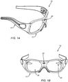
FIGS. 1A and 1B are perspective and front views, respectively, of a wearable gaze tracking device. -
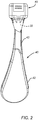
FIG. 2 is a perspective view of an eye imaging module including a waveguide and camera module that may be included in the wearable device ofFIGS. 1A and IB. -
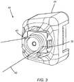
FIG. 3 is a detail of the eye imaging module ofFIG. 2 showing a camera of the module. - FIG. is a detail showing the eye imaging module of
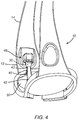
FIG. 2 being incorporated into the wearable device ofFIGS. 1A and IB. -
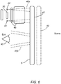
FIG. 5 is a schematic representation of components of the wearable device ofFIGS. 1A and IB. -
FIGS. 6-8 are schematic representations of the wearable device shown inFIG. 5 configured to operate in different modes, including an illumination mode, an imaging mode, and a viewing mode, respectively. -
FIG. 9 is a schematic representation of a wearable device configured to operate in different modes configured for outdoor eye tracking. -
FIGS. 10 and11 are schematic representations of the wearable device ofFIG. 9 configured to operate in different modes, including ambient illumination mode and an edge illumination mode, respectively. - Turning to the drawings,
FIGS. 1-5 show a wearable eye and/or gaze tracking device orsystem 10. The devices, systems, and methods herein may provide a modular wearable gaze tracking device that is optimized for mobile use in a variety of applications, including those where the benefit of gaze-mapping augments other mobile devices currently deployed. The devices, systems, and methods herein may be optimized and/or sufficiently robust for outdoor or other environmental illumination conditions, thereby expanding the number of applications where the benefit of eye and/or gaze-tracking may be employed. - Generally, as shown in
FIG. 1 , thedevice 10 includes awearable device 12, e.g., a frame for glasses (as shown), or a mask, a headset, a helmet, and the like that is configured to be worn on a user's head (not shown), an exo-camera 20 mounted on the device to image the user's surroundings, an endo-camera 30 mounted on the device to image one or more both of the user's eyes (oneeye 90 shown inFIG. 5 ), a freeformoptical assembly 40, and afreeform compensator lens 50. In addition, as shown inFIG. 5 , thedevice 10 may include one or morelight sources 44, e.g., included on theoptical assembly 40 and/or mounted elsewhere on thewearable device 12. Thedevice 10 may also include one or more processors, memory, and the like (not shown) coupled to other components for operating thedevice 10 and/or performing the various functions described herein. Exemplary components, e.g., wearable devices, cameras, light sources, processors, communication interfaces, and the like, that may be included in thedevice 10 are disclosed inU.S. Patent Nos. 6,541,081 and7,488,294 , andU.S. Publication Nos. 2011/ 0211056 and2013/ 0114850 . - With reference to
FIGS. 2-5 , theoptical assembly 40 of thedevice 10 may include multiple components, e.g., a waveguide or endo-freeform optic 42, one or more light sources, 44, and awavelength selection assembly 46, e.g., for focusing and/or filtering light passing therethrough. Thewaveguide 42 may be optically coupled to the endo-camera 30 and/or the light source(s) 44, e.g., via thewavelength selection assembly 46, which may be contained within acamera module housing 48, as shown inFIGS. 2 and3 , e.g., such thatwaveguide 42 is removably or permanently attached to thehousing 48. - The
waveguide 42 may be an integral optical device shaped and/or otherwise configured to fold an optical path of theoptical assembly 40, e.g., to direct illumination from the light source(s) 44 towards aneye 90 of the user, and/or collect light from theeye 90 of the user to acquire images using the endo-camera 30, as described elsewhere herein. For example, thewaveguide 42 may include one or more prisms and/or other optical features integrally formed therein such that light directed into an end or edge of thewaveguide 42, e.g., end 43 coupled to the endo-camera 30, is transmitted within thewaveguide 42, e.g., reflecting off one or more surfaces therein, towards an opposite end of the waveguide, and reflected out of a predetermined surface, e.g.,inner surface 42b towards aneye 90 of the user, e.g., to illuminate theeye 90. Conversely, light entering the predetermined surface, e.g.,inner surface 42b from theeye 90, may be transmitted within thewaveguide 42 back towards theend 43 coupled to the endo-camera 30, e.g., to capture images of theeye 90. - In addition, the
waveguide 42 may have an outward-facingsurface 42a that matches an eye-frame base curve, e.g., corresponding to an inward-facingsurface 50b of thecompensator lens 50, as shown schematically inFIG. 5 . Thus, thewaveguide 42 andcompensator lens 50 together may allow substantially undistorted viewing by the user'seye 90 therethrough into the user's surroundings, e.g., based on normal vision or a predetermined corrective prescription. Thewaveguide 42 may also be sized to at least partially and/or entirely cover an eye opening in theframe 12, e.g., within which thecompensator lens 50 is mounted. Optionally, thewaveguide 42 may include one or more application-specific coatings for optimal performance, e.g., on the outward-facingsurface 42a, on an inward-facingsurface 42b, and/or contained within the waveguide material. - Optionally, one or more components of the
device 10 may be interchangeable, e.g., to allow different size, shape, and/or other configurations of components to be exchanged, e.g., from a modular kit, as desired based on a particular individual user. For example, a first waveguide 42 (coupled to the camera 44) may be replaced with a different waveguide (not shown), e.g., to correspond to a different user's prescription. Alternatively, thefirst waveguide 42 may be removed from aglasses frame 12 and placed into a helmet, pair of goggles, or other wearable device (not shown), e.g., such that the same user may use different wearable devices and still accommodate eye and/or gaze tracking. Multiple design solutions are envisioned for integration into goggles, masks, sunglasses, and the like. - Any of the optical components of the
device 10 shown schematically inFIG. 5 may be modular. For example, thewaveguide 42 may be removably coupled to thehousing 48, e.g., using one or more connectors (not shown) on the connecting end of thewaveguide 42 and/or thehousing 48. As shown inFIG. 4 , thehousing 48 may be permanently or removably attached theframe 12, e.g., on a temple piece orear support 14 of theframe 12. Thehousing 48 may be sufficiently secure and thewaveguide 42 sufficiently rigid that thewaveguide 42 may be secured against or adjacent thecompensator lens 50 when thehousing 48 is secured to frame 12. Alternatively, thewaveguide 42 and theframe 12 and/orcompensator lens 50 may include one or more connectors (not shown) for securing thewaveguide 42 relative to thecompensator lens 50. - In addition or alternatively, the endo-
camera 30 and/orwavelength selection assembly 46 may be removably mounted within thehousing 48, as desired. As shown, one or morelight sources 44 may be placed generally coplanar with and/or located near the endo-camera 30, e.g., mounted within thehousing 48, and/or one or morelight sources 44 may be mounted at an edge of thewaveguide 42, e.g., on one end such that the light source(s) may generate light into thewaveguide 42, which may direct the light towards the user'seye 90. Optionally, thehousing 48 may also include one or more processors, e.g., FPGAs, ASICs, and the like, and/or memory components therein, or such components may be mounted elsewhere on theframe 12 and electrically coupled to thehousing 48 and/or the components therein. - The
device 10 may be operated in one or more modes, as desired, e.g., to allow illumination and/or imaging of theeye 90. For example, as shown inFIG. 6 , an illumination mode is shown in which a pair oflight sources 44 are mounted substantially co-planar with a sensor, e.g., a CMOS, CCD or other imaging chip, of the endo-camera 30. Thus, emitted light, represented byrays 45a may emitted by thelight sources 44 through thewavelength selection assembly 46 into thewaveguide 42, which may direct the light towards theeye 90, as represented byrays 45b. In this manner, thelight sources 44 may illuminate theeye 90 in a desired manner, e.g., to produce one or more glints, and the like. - In addition, turning to
FIG. 7 , an eye-imaging mode is shown in which light reflected from theeye 90, e.g., specularly and/or diffusely, as represented byrays 47a, is collected by thefreeform waveguide 42 and directed back to thecoupling optics 46, which focus the light onto the endo-camera 30, as represented by rays 47b. - Turning to
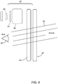
FIG. 8 , the pairing of thewaveguide 42 and thecompensator lens 50 may allow light from the scene, i.e., the user's surroundings, as represented byrays 49, to propagate to the user'seye 90, e.g., with minimal distortion at the entrance pupil of theeye 90. - For example, the
device 10 shown inFIG. 1 may be configured to selectively operate in any one of these modes. Application-specific hardware, software modules, and/or other processing functions, and connectivity may be provided on thedevice 10 to create a family of gaze-tracking devices, e.g., each capable of operating in any of these modes, as desired. The application-specific hardware and connectivity may function on a basic level to serialize a data stream, e.g., from the exo-camera 20 and/or endo-camera 30, and send it to a processing unit, e.g., to the processor(s) on thedevice 10 and/or to a remote electronic device (not shown), e.g., wirelessly or via a wired connection (also not shown). Other optional features may include DSP (e.g., undistort), first-in-process algorithmic modules, and/or full calculation of the gaze vector. Any combination of these may be implemented by the device, e.g., based on available power and/or bandwidth requirements. - The
device 10 may be capable of three-dimensional (3D) point-of-regard (POR) determinations and may include one or more of the following features: - a) saving user calibration data;
- b) virtual plane gaze mapping algorithm for POR modeling;
- c) algorithms for calibrating rotation and/or translation of endo-
camera 30 to exo-camera 20; and/or - d) streaming gaze mapping data wirelessly to a mobile device (e.g., Windows-based OS, Linux-based, and the like).
- Turning to
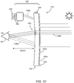
FIGS. 9-11 , an eye and/gaze tracking device 110 is shown that may include components generally similar to the other examples described elsewhere herein, e.g., a frame or other wearable device (not shown), carrying one or more components, such as one or more endo-cameras 130 (one shown inFIGS. 10 and11 for imaging a corresponding eye 90), an exo-camera (not shown), and a freeformoptical assembly 140, e.g., including a waveguide or endo-freeform optic 142, and one or morelight sources 144, generally similar to other examples described elsewhere. Unlike previous examples, thewaveguide 142 includes one or more features, e.g., a plurality of blazed notches orwedges 143 formed therein, e.g., to generate glints, as described further below, which may enhance use of thedevice 110 for eye and/or gaze tracking in outdoor or other brightly illuminated environments. In particular, the "blazes" 143 may act alternatively as transmissive or reflective, e.g., based on the angle of the light striking them, as described further below. Theblazes 143 may formed in the waveguide 1422 using a variety of methods, including laser ablation. - The
device 110 may be operated in more than one mode, e.g., using a bimodal illumination scheme to take advantage of high luminance ambient conditions. For example, under bright ambient light conditions, the pairing of thewaveguide 142 and thecompensator lens 150 allow light from the scene to propagate through thewaveguide 142 andcompensator lens 150 onto the user'seye 90, e.g., as represented byrays 149a inFIG. 10 , with minimal distortion at the entrance pupil of theeye 90. - More particularly, as shown in
FIG. 10 , theblazes 143 allow ambient light to pass through them and thewaveguide 142 to strike theeye 90 in a desired pattern or configuration, and generate a predetermined pattern of glints, which are reflected back into thewaveguide 142 and directed to the endo-camera 130, as represented byrays 149b, 194c. Thus, for ambient or "scene" illumination sources, such as sunlight, the blazes operate in transmission. - Conversely, as shown in
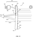
FIG. 11 , when ambient lighting is insufficient, one or moreedge illumination sources 144 may be used to direct light into thewaveguide 14, as represented by rays 145a, and theblazes 143 may operate in reflection to direct light towards theeye 90, as represented byrays 145b. Reflected light may be reflected back into thewaveguide 142 and directed to the endo-camera 130, as represented by rays 145c. Thedevice 110 may include an ambient light sensor (not shown), which may be used, e.g., by the one or more processors of thedevice 10, to regulate light source current to the light source(s) 144 for switching the device between indoor and outdoor applications in real-time. Thus, if the processor(s) determine based on the ambient light sensor that ambient light is sufficient, the light source(s) 144 may be switched off or remain inactive, while if the ambient light is insufficient, the light source(s) 144 may activated as needed for a desired eye-tracking method. - Proper wavelength control may be important in a multimodal system such as the
device 110. To facilitate this, a short-pass dielectric coating (not shown) may be provided on thewaveguide 142 and/orcompensator lens 150, e.g., on their outwardly-facingsurfaces blazes 143 may be configured such that the center wavelength in the light source(s) 144 is preferentially refracted, reflected, and/or diffracted toward theeye 90 of the user. - Similar to the
device 10 shown inFIG. 7 , thedevice 110 may also be operated in an eye-imaging mode. The light reflected from the eye 90 (specularly and diffusely), represented byrays 47a inFIG. 7 , may collected by thewaveguide 140 and directed back to thewavelength selection assembly 146, which focuses the light onto the endo-camera 130 (shown inFIGS. 10 and11 ). A longpass or notch filter in thewavelength selection assembly 146 may be used to reduce noise due to extraneous corneo-schleral reflections in visible wavelengths. Additionally, incorporation of a polarized light source and/or polarization-sensitive components may also reduce environmental noise. - Optionally, the compensator lens 150 (or the compensator lens of any other embodiment herein) may be a sunglass lens, e.g., a tinted, filtered, and/or polarized lens, to reduce the amount of light reaching the user's eye, which may allow the user to relax their eyelids and iris and/or otherwise facilitate eye and/or gaze tracking. Any tinting in the
compensator lens 150 may be permanent or may the lens may be transition-coated. In addition or alternatively, thecompensator lens 150 may be substantially permanently mounted in the frame or may be removable, such that different compensation lenses may be interchangeable in thedevice 110. - Another approach may be to provide dynamic control of the opacity of the
waveguide 142 and/orcompensator lens 150 based on light levels within images collected from the endo-camera(s) 130 used to track the user's eye(s) 90. For example, a system may be provided to electrically control the opacity (or conversely, the transparency) of thelens eye 90 of the user. Suspended elongated particles may be provided within thewaveguide 142 and/orcompensator lens 150 to provide a suspended particle device (SPD), and a circuit may be provided on the device to apply a predetermined voltage to align the elongated particles in orientations to either block or allow the transmission of light. Other electrochromic devices and/or methods, e.g., using polymer dispersed liquid crystals and/or electro-wetting surfaces may be provided. Such electrochromism methods may be used independent of, or in conjunction with, photochromism methods to control opacity. Such features may be included in any of the examples herein. - A key challenge in outdoor and/or harsh lighting environments is the ability to substantially continuously track eye locations during times when overall lighting from environmental sources continuously changes. As mentioned elsewhere herein, this may be partially mitigated by selectively blocking environmental sources of light over the range of wavelengths used to illuminate and/or track the user's eye. In addition or alternatively, a high dynamic range sensor may be included in the endo-camera.
- An additional approach may include dynamically adjusting illumination generated within the
device 110, e.g., by light source(s) 144, to compensate for increases or decreases in environmental illumination. Light levels recorded within images the endo-camera(s) 130 used to track the eye(s) 90 may be used to monitor and subsequently control illumination of the eye(s) 90. This may include selectively illuminating the left or right eye. It may also include preferentially augmenting the illumination of a region or subset of theeye 90 based on light intensities recorded in different regions of camera images, e.g., similar to the systems and methods disclosed in the references elsewhere herein. - Further, it may be useful to consider multiple approaches to pupil detection, where if sufficient pupil is exposed, an edge and/or blob detection method may be implemented to locate the contours of the pupil. If insufficient pupil is exposed, identifying the eyelid contours and/or iris edges instead of the pupil contour may enable a small region containing the pupil center to be identified. After which algorithms may be implemented to fit the pupil to an ellipse and determine the pupil center, e.g., Starburt and Ransac. Additional possibilities include the use of multiple cameras to improve feature capture and reduce processing.
- Once the gaze-mapping system is truly mobile and environmentally robust, the range of possible use-cases increases significantly. For example, warehouse inventory, referring to blueprints during construction inspection, and expert-novice athletic training using mobile eye tracking systems may be enhanced by the robustness to frame movement, eye control, and/or outdoor functionality, as described elsewhere herein.
- It will be appreciated that elements or components shown with any embodiment herein are exemplary for the specific embodiment and may be used on or in combination with other embodiments disclosed herein.
Claims (7)
- A method for taking a digital photo, comprising:activating, at a wearable device (12) including a scene camera (20) oriented to capture images of a user's surroundings, a photo feature of the wearable device in response to the user gazing at a predetermined location of the wearable device; characterized by the further steps of:determining, by the wearable device (12), in response to the user gazing at a center point of an image, a focal point for an imaging field of the scene camera based on the center point;determining, by the wearable device (12), in response to the user gazing at opposite corners of a virtual frame of a region within the user's surroundings, a limited field-of-view for an imaging field of the scene camera based upon the opposite corners; andcapturing, with the scene camera (20), an image of the limited field-of-view centered around the focal point.
- The method of claim 1, wherein the predetermined action comprises the user gazing at a Take Photo LED on the wearable device (12).
- The method of claim 2, wherein activating the photo feature is in response to the user gazing at the Take Photo LED on the wearable device (12) until the wearable device changes the LED to indicate the photo feature is active.
- The method of claim 3, wherein the LED changes color to indicate that the photo feature is active.
- A device (10) for taking a digital photo, comprising:a wearable device (12) configured to be worn on a user's head;an endo-camera (30, 130) on the wearable device (12) configured for obtaining eye tracking images of the eye when the wearable device is worn by the user;an exo-camera (20) on the wearable device (12) configured for obtaining images of the user's surroundings when the wearable device is worn by the user; andone or more processors coupled to the endo-camera (30,130) and configured todetermine when the user performs a predetermined action with the user's eye to activate a photo feature of the wearable device (12), the one or more processors being further coupled to the exo-camera (20);characterized in that the one or more processors are configured to:determine when the user gazes at a center point of an image, and determine a focal point for an imaging field of the exo-camera (20) based on the center point;determine when the user gazes at opposite corners of a virtual frame of a region within the user's surroundings, and determine a limited field-of-view for an imaging field of the exo-camera (20) based on the opposite corners; andactivate the exo-camera to capture an image of the limited field-of-view centered around the focal point.
- The device of claim 5, further comprising a Take Photo LED on the wearable device (12), wherein the predetermined action comprises the user gazing at the Take Photo LED.
- The device of claim 6, wherein the one or more processors are coupled to the Take Photo LED such that the one or more processors change a color of the LED to indicate the photo feature is active in response to the user gazing at the Take Photo LED.
Applications Claiming Priority (4)
| Application Number | Priority Date | Filing Date | Title |
|---|---|---|---|
| US201261734294P | 2012-12-06 | 2012-12-06 | |
| US201261734342P | 2012-12-06 | 2012-12-06 | |
| US201261734354P | 2012-12-06 | 2012-12-06 | |
| PCT/US2013/073753 WO2014089542A1 (en) | 2012-12-06 | 2013-12-06 | Eye tracking wearable devices and methods for use |
Publications (3)
| Publication Number | Publication Date |
|---|---|
| EP2929413A1 EP2929413A1 (en) | 2015-10-14 |
| EP2929413A4 EP2929413A4 (en) | 2016-07-13 |
| EP2929413B1 true EP2929413B1 (en) | 2020-06-03 |
Family
ID=50884065
Family Applications (1)
| Application Number | Title | Priority Date | Filing Date |
|---|---|---|---|
| EP13860881.5A Active EP2929413B1 (en) | 2012-12-06 | 2013-12-06 | Eye tracking wearable devices and methods for use |
Country Status (6)
| Country | Link |
|---|---|
| US (2) | US20140218281A1 (en) |
| EP (1) | EP2929413B1 (en) |
| JP (1) | JP6498606B2 (en) |
| KR (1) | KR102205374B1 (en) |
| CN (1) | CN104903818B (en) |
| WO (1) | WO2014089542A1 (en) |
Families Citing this family (177)
| Publication number | Priority date | Publication date | Assignee | Title |
|---|---|---|---|---|
| US9158116B1 (en) | 2014-04-25 | 2015-10-13 | Osterhout Group, Inc. | Temple and ear horn assembly for headworn computer |
| US9715112B2 (en) | 2014-01-21 | 2017-07-25 | Osterhout Group, Inc. | Suppression of stray light in head worn computing |
| US9400390B2 (en) | 2014-01-24 | 2016-07-26 | Osterhout Group, Inc. | Peripheral lighting for head worn computing |
| US9366867B2 (en) | 2014-07-08 | 2016-06-14 | Osterhout Group, Inc. | Optical systems for see-through displays |
| US20140218281A1 (en) | 2012-12-06 | 2014-08-07 | Eyefluence, Inc. | Systems and methods for eye gaze determination |
| KR102093198B1 (en) * | 2013-02-21 | 2020-03-25 | 삼성전자주식회사 | Method and apparatus for user interface using gaze interaction |
| KR102256992B1 (en) * | 2013-04-25 | 2021-05-27 | 에씰로 앙터나시오날 | A method of controlling a head mounted electro-optical device adapted to a wearer |
| US9710058B2 (en) * | 2013-09-03 | 2017-07-18 | Tobii Ab | Portable eye tracking device |
| KR102094965B1 (en) * | 2013-12-30 | 2020-03-31 | 삼성디스플레이 주식회사 | Awareness glasses, car mirror unit and display apparatus |
| US10024679B2 (en) | 2014-01-14 | 2018-07-17 | Toyota Motor Engineering & Manufacturing North America, Inc. | Smart necklace with stereo vision and onboard processing |
| US10248856B2 (en) | 2014-01-14 | 2019-04-02 | Toyota Motor Engineering & Manufacturing North America, Inc. | Smart necklace with stereo vision and onboard processing |
| US9915545B2 (en) * | 2014-01-14 | 2018-03-13 | Toyota Motor Engineering & Manufacturing North America, Inc. | Smart necklace with stereo vision and onboard processing |
| US9578307B2 (en) * | 2014-01-14 | 2017-02-21 | Toyota Motor Engineering & Manufacturing North America, Inc. | Smart necklace with stereo vision and onboard processing |
| US10360907B2 (en) | 2014-01-14 | 2019-07-23 | Toyota Motor Engineering & Manufacturing North America, Inc. | Smart necklace with stereo vision and onboard processing |
| US9594246B2 (en) | 2014-01-21 | 2017-03-14 | Osterhout Group, Inc. | See-through computer display systems |
| US10649220B2 (en) | 2014-06-09 | 2020-05-12 | Mentor Acquisition One, Llc | Content presentation in head worn computing |
| US20150228119A1 (en) | 2014-02-11 | 2015-08-13 | Osterhout Group, Inc. | Spatial location presentation in head worn computing |
| US10254856B2 (en) | 2014-01-17 | 2019-04-09 | Osterhout Group, Inc. | External user interface for head worn computing |
| US9829707B2 (en) | 2014-08-12 | 2017-11-28 | Osterhout Group, Inc. | Measuring content brightness in head worn computing |
| US10684687B2 (en) | 2014-12-03 | 2020-06-16 | Mentor Acquisition One, Llc | See-through computer display systems |
| US11669163B2 (en) | 2014-01-21 | 2023-06-06 | Mentor Acquisition One, Llc | Eye glint imaging in see-through computer display systems |
| US9753288B2 (en) | 2014-01-21 | 2017-09-05 | Osterhout Group, Inc. | See-through computer display systems |
| US11487110B2 (en) | 2014-01-21 | 2022-11-01 | Mentor Acquisition One, Llc | Eye imaging in head worn computing |
| US11892644B2 (en) | 2014-01-21 | 2024-02-06 | Mentor Acquisition One, Llc | See-through computer display systems |
| US11737666B2 (en) | 2014-01-21 | 2023-08-29 | Mentor Acquisition One, Llc | Eye imaging in head worn computing |
| US20160018652A1 (en) | 2014-01-24 | 2016-01-21 | Osterhout Group, Inc. | See-through computer display systems |
| US9846308B2 (en) | 2014-01-24 | 2017-12-19 | Osterhout Group, Inc. | Haptic systems for head-worn computers |
| GB2526515A (en) * | 2014-03-25 | 2015-12-02 | Jaguar Land Rover Ltd | Image capture system |
| US9651787B2 (en) | 2014-04-25 | 2017-05-16 | Osterhout Group, Inc. | Speaker assembly for headworn computer |
| US10853589B2 (en) | 2014-04-25 | 2020-12-01 | Mentor Acquisition One, Llc | Language translation with head-worn computing |
| US20160137312A1 (en) | 2014-05-06 | 2016-05-19 | Osterhout Group, Inc. | Unmanned aerial vehicle launch system |
| US10564714B2 (en) | 2014-05-09 | 2020-02-18 | Google Llc | Systems and methods for biomechanically-based eye signals for interacting with real and virtual objects |
| KR20170046108A (en) | 2014-05-09 | 2017-04-28 | 아이플루언스, 인크. | Systems and methods for using eye signals with secure mobile communications |
| US10663740B2 (en) | 2014-06-09 | 2020-05-26 | Mentor Acquisition One, Llc | Content presentation in head worn computing |
| US9818114B2 (en) | 2014-08-11 | 2017-11-14 | Mastercard International Incorporated | Systems and methods for performing payment card transactions using a wearable computing device |
| US10448867B2 (en) | 2014-09-05 | 2019-10-22 | Vision Service Plan | Wearable gait monitoring apparatus, systems, and related methods |
| US10617342B2 (en) | 2014-09-05 | 2020-04-14 | Vision Service Plan | Systems, apparatus, and methods for using a wearable device to monitor operator alertness |
| US11918375B2 (en) | 2014-09-05 | 2024-03-05 | Beijing Zitiao Network Technology Co., Ltd. | Wearable environmental pollution monitor computer apparatus, systems, and related methods |
| US10024678B2 (en) | 2014-09-17 | 2018-07-17 | Toyota Motor Engineering & Manufacturing North America, Inc. | Wearable clip for providing social and environmental awareness |
| US9922236B2 (en) | 2014-09-17 | 2018-03-20 | Toyota Motor Engineering & Manufacturing North America, Inc. | Wearable eyeglasses for providing social and environmental awareness |
| US9568603B2 (en) * | 2014-11-14 | 2017-02-14 | Microsoft Technology Licensing, Llc | Eyewear-mountable eye tracking device |
| US9704038B2 (en) | 2015-01-07 | 2017-07-11 | Microsoft Technology Licensing, Llc | Eye tracking |
| US10215568B2 (en) | 2015-01-30 | 2019-02-26 | Vision Service Plan | Systems and methods for tracking motion, performance, and other data for an individual such as a winter sports athlete |
| US10490102B2 (en) | 2015-02-10 | 2019-11-26 | Toyota Motor Engineering & Manufacturing North America, Inc. | System and method for braille assistance |
| US10878775B2 (en) | 2015-02-17 | 2020-12-29 | Mentor Acquisition One, Llc | See-through computer display systems |
| US9972216B2 (en) | 2015-03-20 | 2018-05-15 | Toyota Motor Engineering & Manufacturing North America, Inc. | System and method for storing and playback of information for blind users |
| CN112882233B (en) | 2015-05-19 | 2023-08-01 | 奇跃公司 | Double composite light field device |
| KR20240009542A (en) * | 2015-05-20 | 2024-01-22 | 매직 립, 인코포레이티드 | Tilt shift iris imaging |
| US9898865B2 (en) | 2015-06-22 | 2018-02-20 | Microsoft Technology Licensing, Llc | System and method for spawning drawing surfaces |
| US9939644B2 (en) * | 2015-06-25 | 2018-04-10 | Intel Corporation | Technologies for controlling vision correction of a wearable computing device |
| US10139966B2 (en) | 2015-07-22 | 2018-11-27 | Osterhout Group, Inc. | External user interface for head worn computing |
| US11003246B2 (en) | 2015-07-22 | 2021-05-11 | Mentor Acquisition One, Llc | External user interface for head worn computing |
| JP2017060078A (en) * | 2015-09-18 | 2017-03-23 | カシオ計算機株式会社 | Image recording system, user attachment device, imaging apparatus, image processing system, image recording method, and program |
| US10618521B2 (en) * | 2015-09-21 | 2020-04-14 | Ford Global Technologies, Llc | Wearable in-vehicle eye gaze detection |
| US11064881B2 (en) * | 2015-11-13 | 2021-07-20 | Hennepin Healthcare System, Inc | Method for predicting convergence disorders caused by concussion or other neuropathology |
| US11144107B2 (en) | 2015-12-01 | 2021-10-12 | Amer Sports Digital Services Oy | Apparatus and method for presenting thematic maps |
| US11210299B2 (en) | 2015-12-01 | 2021-12-28 | Amer Sports Digital Services Oy | Apparatus and method for presenting thematic maps |
| US11137820B2 (en) | 2015-12-01 | 2021-10-05 | Amer Sports Digital Services Oy | Apparatus and method for presenting thematic maps |
| US11215457B2 (en) | 2015-12-01 | 2022-01-04 | Amer Sports Digital Services Oy | Thematic map based route optimization |
| DE102016015066A1 (en) * | 2015-12-21 | 2017-06-22 | Suunto Oy | Activity intensity level determination |
| US11284807B2 (en) | 2015-12-21 | 2022-03-29 | Amer Sports Digital Services Oy | Engaging exercising devices with a mobile device |
| US10433768B2 (en) | 2015-12-21 | 2019-10-08 | Amer Sports Digital Services Oy | Activity intensity level determination |
| US11838990B2 (en) | 2015-12-21 | 2023-12-05 | Suunto Oy | Communicating sensor data in wireless communication systems |
| US11587484B2 (en) | 2015-12-21 | 2023-02-21 | Suunto Oy | Method for controlling a display |
| US11541280B2 (en) | 2015-12-21 | 2023-01-03 | Suunto Oy | Apparatus and exercising device |
| FI127926B (en) | 2015-12-21 | 2019-05-31 | Suunto Oy | Sensor based context management |
| DE102016015695A1 (en) | 2015-12-21 | 2017-06-22 | Suunto Oy | Activity intensity level determination |
| WO2017116662A1 (en) * | 2015-12-28 | 2017-07-06 | Artilux Corporation | Eye gesture tracking |
| CN113156650A (en) * | 2016-01-19 | 2021-07-23 | 奇跃公司 | Augmented reality system and method using images |
| US10850116B2 (en) | 2016-12-30 | 2020-12-01 | Mentor Acquisition One, Llc | Head-worn therapy device |
| US10591728B2 (en) | 2016-03-02 | 2020-03-17 | Mentor Acquisition One, Llc | Optical systems for head-worn computers |
| US10667981B2 (en) | 2016-02-29 | 2020-06-02 | Mentor Acquisition One, Llc | Reading assistance system for visually impaired |
| US9826299B1 (en) | 2016-08-22 | 2017-11-21 | Osterhout Group, Inc. | Speaker systems for head-worn computer systems |
| US9880441B1 (en) | 2016-09-08 | 2018-01-30 | Osterhout Group, Inc. | Electrochromic systems for head-worn computer systems |
| WO2017155826A1 (en) * | 2016-03-07 | 2017-09-14 | Magic Leap, Inc. | Blue light adjustment for biometri security |
| US10024680B2 (en) | 2016-03-11 | 2018-07-17 | Toyota Motor Engineering & Manufacturing North America, Inc. | Step based guidance system |
| US10466491B2 (en) | 2016-06-01 | 2019-11-05 | Mentor Acquisition One, Llc | Modular systems for head-worn computers |
| US10082866B2 (en) | 2016-04-12 | 2018-09-25 | International Business Machines Corporation | Gaze point detection using dynamic facial reference points under varying lighting conditions |
| US9958275B2 (en) | 2016-05-31 | 2018-05-01 | Toyota Motor Engineering & Manufacturing North America, Inc. | System and method for wearable smart device communications |
| US10561519B2 (en) | 2016-07-20 | 2020-02-18 | Toyota Motor Engineering & Manufacturing North America, Inc. | Wearable computing device having a curved back to reduce pressure on vertebrae |
| EP3276327B1 (en) | 2016-07-29 | 2019-10-02 | Essilor International | Method for virtual testing of at least one lens having a predetermined optical feature and associated device |
| WO2018023246A1 (en) * | 2016-07-31 | 2018-02-08 | 杨洁 | Method for pushing information while photographing and eyeglasses |
| WO2018023247A1 (en) * | 2016-07-31 | 2018-02-08 | 杨洁 | Data acquisition method for automatic photographing and technical transmission and glasses |
| WO2018023242A1 (en) * | 2016-07-31 | 2018-02-08 | 杨洁 | Automatic photographing method and glasses |
| WO2018023243A1 (en) * | 2016-07-31 | 2018-02-08 | 杨洁 | Automatic-photographing patent-information push method and eyeglasses |
| WO2018023245A1 (en) * | 2016-07-31 | 2018-02-08 | 杨洁 | Method for automatic photographing and transmission and eyeglasses |
| KR102548199B1 (en) * | 2016-08-03 | 2023-06-28 | 삼성전자주식회사 | Electronic device and method for tracking gaze in the electronic device |
| US10268268B1 (en) | 2016-09-02 | 2019-04-23 | Facebook Technologies, Llc | Waveguide integrated eye tracking |
| JP2018061622A (en) * | 2016-10-11 | 2018-04-19 | オプトス ピーエルシー | Fundus observation apparatus |
| DE102017009171A1 (en) | 2016-10-17 | 2018-04-19 | Amer Sports Digital Services Oy | EMBEDDED APPENDIX |
| US11703938B2 (en) | 2016-10-17 | 2023-07-18 | Suunto Oy | Embedded computing device |
| US10432851B2 (en) | 2016-10-28 | 2019-10-01 | Toyota Motor Engineering & Manufacturing North America, Inc. | Wearable computing device for detecting photography |
| USD827143S1 (en) | 2016-11-07 | 2018-08-28 | Toyota Motor Engineering & Manufacturing North America, Inc. | Blind aid device |
| US10032053B2 (en) | 2016-11-07 | 2018-07-24 | Rockwell Automation Technologies, Inc. | Tag based location |
| US10012505B2 (en) | 2016-11-11 | 2018-07-03 | Toyota Motor Engineering & Manufacturing North America, Inc. | Wearable system for providing walking directions |
| US10521669B2 (en) | 2016-11-14 | 2019-12-31 | Toyota Motor Engineering & Manufacturing North America, Inc. | System and method for providing guidance or feedback to a user |
| US10168531B1 (en) | 2017-01-04 | 2019-01-01 | Facebook Technologies, Llc | Lightfield waveguide integrated eye tracking |
| US10485420B2 (en) * | 2017-02-17 | 2019-11-26 | Analog Devices Global Unlimited Company | Eye gaze tracking |
| US20180255250A1 (en) * | 2017-03-03 | 2018-09-06 | Microsoft Technology Licensing, Llc | Pulsed, gated infrared illuminated camera systems and processes for eye tracking in high ambient light environments |
| CN106842625B (en) * | 2017-03-03 | 2020-03-17 | 西南交通大学 | Target tracking method based on feature consensus |
| CN114125661A (en) | 2017-03-30 | 2022-03-01 | 奇跃公司 | Sound reproduction system and head-mounted device |
| US10977858B2 (en) | 2017-03-30 | 2021-04-13 | Magic Leap, Inc. | Centralized rendering |
| CA3058669A1 (en) | 2017-04-14 | 2018-10-18 | Magic Leap, Inc. | Multimodal eye tracking |
| US9910298B1 (en) | 2017-04-17 | 2018-03-06 | Vision Service Plan | Systems and methods for a computerized temple for use with eyewear |
| US20180336772A1 (en) * | 2017-05-19 | 2018-11-22 | Hcl Technologies Limited | System and method for alerting a user within a warehouse |
| US11079522B1 (en) | 2017-05-31 | 2021-08-03 | Magic Leap, Inc. | Fiducial design |
| EP4123425A1 (en) * | 2017-05-31 | 2023-01-25 | Magic Leap, Inc. | Eye tracking calibration techniques |
| US10810773B2 (en) * | 2017-06-14 | 2020-10-20 | Dell Products, L.P. | Headset display control based upon a user's pupil state |
| CN111133364B (en) * | 2017-07-13 | 2021-11-09 | 华为技术有限公司 | Dual-mode earphone |
| US10422995B2 (en) | 2017-07-24 | 2019-09-24 | Mentor Acquisition One, Llc | See-through computer display systems with stray light management |
| US11409105B2 (en) | 2017-07-24 | 2022-08-09 | Mentor Acquisition One, Llc | See-through computer display systems |
| US10578869B2 (en) | 2017-07-24 | 2020-03-03 | Mentor Acquisition One, Llc | See-through computer display systems with adjustable zoom cameras |
| US10969584B2 (en) | 2017-08-04 | 2021-04-06 | Mentor Acquisition One, Llc | Image expansion optic for head-worn computer |
| CN115175064A (en) | 2017-10-17 | 2022-10-11 | 奇跃公司 | Mixed reality spatial audio |
| FI20175960A1 (en) | 2017-10-30 | 2019-05-01 | Univ Of Eastern Finland | Method and apparatus for gaze detection |
| US11181977B2 (en) * | 2017-11-17 | 2021-11-23 | Dolby Laboratories Licensing Corporation | Slippage compensation in eye tracking |
| USD849822S1 (en) * | 2017-12-29 | 2019-05-28 | Aira Tech Corp. | Smart glasses for interactive use cases |
| US11393251B2 (en) | 2018-02-09 | 2022-07-19 | Pupil Labs Gmbh | Devices, systems and methods for predicting gaze-related parameters |
| US11194161B2 (en) | 2018-02-09 | 2021-12-07 | Pupil Labs Gmbh | Devices, systems and methods for predicting gaze-related parameters |
| US11556741B2 (en) | 2018-02-09 | 2023-01-17 | Pupil Labs Gmbh | Devices, systems and methods for predicting gaze-related parameters using a neural network |
| CA3090281A1 (en) | 2018-02-15 | 2019-08-22 | Magic Leap, Inc. | Dual listener positions for mixed reality |
| CA3090178A1 (en) | 2018-02-15 | 2019-08-22 | Magic Leap, Inc. | Mixed reality musical instrument |
| JP2021514081A (en) | 2018-02-15 | 2021-06-03 | マジック リープ, インコーポレイテッドMagic Leap,Inc. | Mixed reality virtual echo |
| WO2019185150A1 (en) * | 2018-03-29 | 2019-10-03 | Tobii Ab | Determining a gaze direction using depth information |
| WO2019190561A1 (en) * | 2018-03-30 | 2019-10-03 | Tobii Ab | Deep learning for three dimensional (3d) gaze prediction |
| US10558895B2 (en) * | 2018-03-30 | 2020-02-11 | Tobii Ab | Deep learning for three dimensional (3D) gaze prediction |
| US10281085B1 (en) * | 2018-03-30 | 2019-05-07 | Faspro Systems Co., Ltd. | Head-mounted wireless photographic apparatus |
| CN110557552A (en) * | 2018-05-31 | 2019-12-10 | 联想企业解决方案(新加坡)有限公司 | Portable image acquisition equipment |
| US10667072B2 (en) | 2018-06-12 | 2020-05-26 | Magic Leap, Inc. | Efficient rendering of virtual soundfields |
| EP3582077A1 (en) * | 2018-06-13 | 2019-12-18 | Tobii AB | Eye tracking device and method for manufacturing an eye tracking device |
| WO2019241760A1 (en) | 2018-06-14 | 2019-12-19 | Magic Leap, Inc. | Methods and systems for audio signal filtering |
| WO2019241754A1 (en) | 2018-06-14 | 2019-12-19 | Magic Leap, Inc. | Reverberation gain normalization |
| EP3808107A4 (en) | 2018-06-18 | 2022-03-16 | Magic Leap, Inc. | Spatial audio for interactive audio environments |
| JP7419270B2 (en) | 2018-06-21 | 2024-01-22 | マジック リープ, インコーポレイテッド | Wearable system speech processing |
| WO2020023419A1 (en) | 2018-07-24 | 2020-01-30 | Magic Leap, Inc. | Application sharing |
| US11179035B2 (en) * | 2018-07-25 | 2021-11-23 | Natus Medical Incorporated | Real-time removal of IR LED reflections from an image |
| US10722128B2 (en) | 2018-08-01 | 2020-07-28 | Vision Service Plan | Heart rate detection system and method |
| KR102574995B1 (en) * | 2018-09-21 | 2023-09-06 | 돌비 레버러토리즈 라이쎈싱 코오포레이션 | Integrating components into the optical stack of head-mounted devices |
| US11094127B2 (en) | 2018-09-25 | 2021-08-17 | Magic Leap, Inc. | Systems and methods for presenting perspective views of augmented reality virtual object |
| CN113170253B (en) | 2018-10-05 | 2024-03-19 | 奇跃公司 | Emphasis for audio spatialization |
| JP7194271B2 (en) | 2018-10-05 | 2022-12-21 | マジック リープ, インコーポレイテッド | Near-field audio rendering |
| WO2020076867A1 (en) | 2018-10-09 | 2020-04-16 | Magic Leap, Inc. | Systems and methods for virtual and augmented reality |
| US11487316B2 (en) | 2018-10-24 | 2022-11-01 | Magic Leap, Inc. | Asynchronous ASIC |
| US10786033B2 (en) * | 2018-10-29 | 2020-09-29 | Robotarmy Corp. | Racing helmet with visual and audible information exchange |
| TWI699671B (en) * | 2018-12-12 | 2020-07-21 | 國立臺灣大學 | Method for reducing operation on eye-tracking and eye-tracking device thereof |
| WO2020140078A1 (en) | 2018-12-27 | 2020-07-02 | Magic Leap, Inc. | Systems and methods for virtual and augmented reality |
| WO2020147948A1 (en) | 2019-01-16 | 2020-07-23 | Pupil Labs Gmbh | Methods for generating calibration data for head-wearable devices and eye tracking system |
| CN113748462A (en) | 2019-03-01 | 2021-12-03 | 奇跃公司 | Determining input for a speech processing engine |
| US10877268B2 (en) * | 2019-04-16 | 2020-12-29 | Facebook Technologies, Llc | Active control of in-field light sources of a head mounted display |
| WO2020231517A1 (en) | 2019-05-10 | 2020-11-19 | Verily Life Sciences Llc | Natural physio-optical user interface for intraocular microdisplay |
| EP3979896A1 (en) | 2019-06-05 | 2022-04-13 | Pupil Labs GmbH | Devices, systems and methods for predicting gaze-related parameters |
| JP7369212B2 (en) | 2019-06-06 | 2023-10-25 | マジック リープ, インコーポレイテッド | Photorealistic character construction for spatial computing |
| US11301677B2 (en) * | 2019-06-14 | 2022-04-12 | Tobil AB | Deep learning for three dimensional (3D) gaze prediction |
| WO2021011686A1 (en) * | 2019-07-16 | 2021-01-21 | Magic Leap, Inc. | Eye center of rotation determination with one or more eye tracking cameras |
| US11328740B2 (en) | 2019-08-07 | 2022-05-10 | Magic Leap, Inc. | Voice onset detection |
| US11704874B2 (en) | 2019-08-07 | 2023-07-18 | Magic Leap, Inc. | Spatial instructions and guides in mixed reality |
| WO2021077024A1 (en) | 2019-10-18 | 2021-04-22 | Magic Leap, Inc. | Gravity estimation and bundle adjustment for visual-inertial odometry |
| EP4049466A4 (en) | 2019-10-25 | 2022-12-28 | Magic Leap, Inc. | Reverberation fingerprint estimation |
| CN115698847A (en) | 2019-12-04 | 2023-02-03 | 奇跃公司 | Variable pitch color emissive display |
| EP4070284A4 (en) | 2019-12-06 | 2023-05-24 | Magic Leap, Inc. | Environment acoustics persistence |
| WO2021119212A1 (en) | 2019-12-09 | 2021-06-17 | Magic Leap, Inc. | Systems and methods for operating a head-mounted display system based on user identity |
| US11337023B2 (en) | 2019-12-20 | 2022-05-17 | Magic Leap, Inc. | Physics-based audio and haptic synthesis |
| CN115398316A (en) | 2020-02-14 | 2022-11-25 | 奇跃公司 | 3D object annotation |
| EP4103999A4 (en) | 2020-02-14 | 2023-08-02 | Magic Leap, Inc. | Session manager |
| US11910183B2 (en) | 2020-02-14 | 2024-02-20 | Magic Leap, Inc. | Multi-application audio rendering |
| US11778410B2 (en) | 2020-02-14 | 2023-10-03 | Magic Leap, Inc. | Delayed audio following |
| EP4104000A4 (en) | 2020-02-14 | 2023-07-12 | Magic Leap, Inc. | Tool bridge |
| US20220342224A1 (en) * | 2020-02-19 | 2022-10-27 | Pupil Labs Gmbh | Eye tracking module and head-wearable device |
| WO2021178454A1 (en) | 2020-03-02 | 2021-09-10 | Magic Leap, Inc. | Immersive audio platform |
| US11917384B2 (en) | 2020-03-27 | 2024-02-27 | Magic Leap, Inc. | Method of waking a device using spoken voice commands |
| EP4158908A4 (en) | 2020-05-29 | 2023-11-29 | Magic Leap, Inc. | Surface appropriate collisions |
| CN116210021A (en) | 2020-05-29 | 2023-06-02 | 奇跃公司 | Determining angular acceleration |
| CN114967904A (en) * | 2021-02-19 | 2022-08-30 | 北京京东方光电科技有限公司 | Sight line positioning method, head-mounted display device, computer device and storage medium |
| US20230122300A1 (en) * | 2021-10-14 | 2023-04-20 | Microsoft Technology Licensing, Llc | Eye-tracking waveguides |
| US11592899B1 (en) | 2021-10-28 | 2023-02-28 | Tectus Corporation | Button activation within an eye-controlled user interface |
| US11619994B1 (en) | 2022-01-14 | 2023-04-04 | Tectus Corporation | Control of an electronic contact lens using pitch-based eye gestures |
| US11874961B2 (en) | 2022-05-09 | 2024-01-16 | Tectus Corporation | Managing display of an icon in an eye tracking augmented reality device |
Citations (1)
| Publication number | Priority date | Publication date | Assignee | Title |
|---|---|---|---|---|
| JP2001281520A (en) * | 2000-03-30 | 2001-10-10 | Minolta Co Ltd | Optical device |
Family Cites Families (114)
| Publication number | Priority date | Publication date | Assignee | Title |
|---|---|---|---|---|
| US3863243A (en) | 1972-01-19 | 1975-01-28 | Max Skolnick | Sleep inhibiting alarm |
| US3798599A (en) | 1972-02-24 | 1974-03-19 | H Kafafian | Single input controller for a communication system |
| US4359724A (en) | 1980-04-28 | 1982-11-16 | Ronald R. Zimmerman | Eyelid movement detector |
| EP0249996B1 (en) | 1986-06-20 | 1992-03-18 | Matsushita Electric Industrial Co., Ltd. | Optical recording and reproducing apparatus |
| US4953111A (en) | 1987-02-12 | 1990-08-28 | Omron Tateisi Electronics Co. | Doze detector |
| US4850691A (en) | 1987-03-18 | 1989-07-25 | University Of Illinois | Method and apparatus for determining pupillary response parameters |
| US4815839A (en) | 1987-08-03 | 1989-03-28 | Waldorf Ronald A | Infrared/video electronystagmographic apparatus |
| US5214456A (en) | 1991-10-09 | 1993-05-25 | Computed Anatomy Incorporated | Mapping of corneal topography with display of pupil perimeter |
| JPH05191683A (en) * | 1992-01-14 | 1993-07-30 | Canon Inc | Photographic recorder |
| US5345281A (en) | 1992-12-17 | 1994-09-06 | John Taboada | Eye tracking system and method |
| US5517021A (en) | 1993-01-19 | 1996-05-14 | The Research Foundation State University Of New York | Apparatus and method for eye tracking interface |
| TW247985B (en) * | 1993-04-22 | 1995-05-21 | Canon Kk | Image-taking apparatus |
| JPH07146431A (en) * | 1993-11-25 | 1995-06-06 | Canon Inc | Camera |
| US5402109A (en) | 1993-04-29 | 1995-03-28 | Mannik; Kallis H. | Sleep prevention device for automobile drivers |
| US5481622A (en) | 1994-03-01 | 1996-01-02 | Rensselaer Polytechnic Institute | Eye tracking apparatus and method employing grayscale threshold values |
| JPH07283974A (en) * | 1994-04-12 | 1995-10-27 | Canon Inc | Video camera with line of sight detector |
| JPH086708A (en) | 1994-04-22 | 1996-01-12 | Canon Inc | Display device |
| CA2126142A1 (en) | 1994-06-17 | 1995-12-18 | David Alexander Kahn | Visual communications apparatus |
| US5469143A (en) | 1995-01-10 | 1995-11-21 | Cooper; David E. | Sleep awakening device for drivers of motor vehicles |
| US5566067A (en) | 1995-03-23 | 1996-10-15 | The President And Fellows Of Harvard College | Eyelid vigilance detector system |
| US5689241A (en) | 1995-04-24 | 1997-11-18 | Clarke, Sr.; James Russell | Sleep detection and driver alert apparatus |
| US5570698A (en) | 1995-06-02 | 1996-11-05 | Siemens Corporate Research, Inc. | System for monitoring eyes for detecting sleep behavior |
| US5682144A (en) | 1995-11-20 | 1997-10-28 | Mannik; Kallis Hans | Eye actuated sleep prevention devices and other eye controlled devices |
| US6003991A (en) | 1996-02-17 | 1999-12-21 | Erik Scott Viirre | Eye examination apparatus and method for remote examination of a patient by a health professional |
| US5912721A (en) | 1996-03-13 | 1999-06-15 | Kabushiki Kaisha Toshiba | Gaze detection apparatus and its method as well as information display apparatus |
| US5886683A (en) | 1996-06-25 | 1999-03-23 | Sun Microsystems, Inc. | Method and apparatus for eyetrack-driven information retrieval |
| US6542081B2 (en) | 1996-08-19 | 2003-04-01 | William C. Torch | System and method for monitoring eye movement |
| US5748113A (en) | 1996-08-19 | 1998-05-05 | Torch; William C. | Method and apparatus for communication |
| US6163281A (en) | 1996-08-19 | 2000-12-19 | Torch; William C. | System and method for communication using eye movement |
| US6246344B1 (en) | 1996-08-19 | 2001-06-12 | William C. Torch | Method and apparatus for voluntary communication |
| US5867587A (en) | 1997-05-19 | 1999-02-02 | Northrop Grumman Corporation | Impaired operator detection and warning system employing eyeblink analysis |
| WO1999018842A1 (en) | 1997-10-16 | 1999-04-22 | The Board Of Trustees Of The Leland Stanford Junior University | Method for inferring mental states from eye movements |
| US6007202A (en) | 1997-10-23 | 1999-12-28 | Lasersight Technologies, Inc. | Eye illumination system and method |
| DE19803158C1 (en) | 1998-01-28 | 1999-05-06 | Daimler Chrysler Ag | Arrangement for determining the state of vigilance, esp. for machinery operator or vehicle driver |
| US6204828B1 (en) | 1998-03-31 | 2001-03-20 | International Business Machines Corporation | Integrated gaze/manual cursor positioning system |
| US6867752B1 (en) | 1998-08-31 | 2005-03-15 | Semiconductor Energy Laboratory Co., Ltd. | Portable information processing system |
| US6243076B1 (en) | 1998-09-01 | 2001-06-05 | Synthetic Environments, Inc. | System and method for controlling host system interface with point-of-interest data |
| US6087941A (en) | 1998-09-01 | 2000-07-11 | Ferraz; Mark | Warning device for alerting a person falling asleep |
| AUPP612998A0 (en) | 1998-09-23 | 1998-10-15 | Canon Kabushiki Kaisha | Multiview multimedia generation system |
| US6526159B1 (en) | 1998-12-31 | 2003-02-25 | Intel Corporation | Eye tracking for resource and power management |
| US6577329B1 (en) | 1999-02-25 | 2003-06-10 | International Business Machines Corporation | Method and system for relevance feedback through gaze tracking and ticker interfaces |
| GB2348520B (en) | 1999-03-31 | 2003-11-12 | Ibm | Assisting user selection of graphical user interface elements |
| US6116736A (en) | 1999-04-23 | 2000-09-12 | Neuroptics, Inc. | Pupilometer with pupil irregularity detection capability |
| JP2001183735A (en) * | 1999-12-27 | 2001-07-06 | Fuji Photo Film Co Ltd | Method and device for image pickup |
| US6456262B1 (en) | 2000-05-09 | 2002-09-24 | Intel Corporation | Microdisplay with eye gaze detection |
| US6608615B1 (en) | 2000-09-19 | 2003-08-19 | Intel Corporation | Passive gaze-driven browsing |
| EP1405122B1 (en) | 2000-10-07 | 2007-07-18 | David Dickerson | Device for determining the orientation of an eye |
| DE10103922A1 (en) | 2001-01-30 | 2002-08-01 | Physoptics Opto Electronic Gmb | Interactive data viewing and operating system |
| US20030038754A1 (en) | 2001-08-22 | 2003-02-27 | Mikael Goldstein | Method and apparatus for gaze responsive text presentation in RSVP display |
| AUPR872301A0 (en) | 2001-11-08 | 2001-11-29 | Sleep Diagnostics Pty Ltd | Alertness monitor |
| US6712468B1 (en) | 2001-12-12 | 2004-03-30 | Gregory T. Edwards | Techniques for facilitating use of eye tracking data |
| US6919907B2 (en) * | 2002-06-20 | 2005-07-19 | International Business Machines Corporation | Anticipatory image capture for stereoscopic remote viewing with foveal priority |
| US20040061680A1 (en) | 2002-07-10 | 2004-04-01 | John Taboada | Method and apparatus for computer control |
| ATE454849T1 (en) * | 2002-10-15 | 2010-01-15 | Volvo Technology Corp | METHOD FOR EVALUATION OF A PERSON'S HEAD AND EYE ACTIVITY |
| US7347551B2 (en) | 2003-02-13 | 2008-03-25 | Fergason Patent Properties, Llc | Optical system for monitoring eye movement |
| US7881493B1 (en) | 2003-04-11 | 2011-02-01 | Eyetools, Inc. | Methods and apparatuses for use of eye interpretation information |
| US9274598B2 (en) | 2003-08-25 | 2016-03-01 | International Business Machines Corporation | System and method for selecting and activating a target object using a combination of eye gaze and key presses |
| US20050047629A1 (en) | 2003-08-25 | 2005-03-03 | International Business Machines Corporation | System and method for selectively expanding or contracting a portion of a display using eye-gaze tracking |
| US7365738B2 (en) | 2003-12-02 | 2008-04-29 | International Business Machines Corporation | Guides and indicators for eye movement monitoring systems |
| JP2005252732A (en) * | 2004-03-04 | 2005-09-15 | Olympus Corp | Imaging device |
| US7561143B1 (en) | 2004-03-19 | 2009-07-14 | The University of the Arts | Using gaze actions to interact with a display |
| GB2412431B (en) * | 2004-03-25 | 2007-11-07 | Hewlett Packard Development Co | Self-calibration for an eye tracker |
| CN102068237A (en) | 2004-04-01 | 2011-05-25 | 威廉·C·托奇 | Controllers and Methods for Monitoring Eye Movement, System and Method for Controlling Calculation Device |
| ES2535364T3 (en) | 2004-06-18 | 2015-05-08 | Tobii Ab | Eye control of computer equipment |
| NZ560528A (en) | 2005-03-04 | 2010-02-26 | Optalert Pty Ltd | Measuring alertness |
| JP2006345276A (en) * | 2005-06-09 | 2006-12-21 | Fujifilm Holdings Corp | Imaging apparatus |
| EP1943583B1 (en) | 2005-10-28 | 2019-04-10 | Tobii AB | Eye tracker with visual feedback |
| US7429108B2 (en) | 2005-11-05 | 2008-09-30 | Outland Research, Llc | Gaze-responsive interface to enhance on-screen user reading tasks |
| US7760910B2 (en) | 2005-12-12 | 2010-07-20 | Eyetools, Inc. | Evaluation of visual stimuli using existing viewing data |
| US8793620B2 (en) | 2011-04-21 | 2014-07-29 | Sony Computer Entertainment Inc. | Gaze-assisted computer interface |
| JP2008288767A (en) | 2007-05-16 | 2008-11-27 | Sony Corp | Information processor, method, and program |
| WO2009073584A1 (en) | 2007-11-29 | 2009-06-11 | Oculis Labs, Inc. | Method and apparatus for display of secure visual content |
| US20100045596A1 (en) | 2008-08-21 | 2010-02-25 | Sony Ericsson Mobile Communications Ab | Discreet feature highlighting |
| US7850306B2 (en) | 2008-08-28 | 2010-12-14 | Nokia Corporation | Visual cognition aware display and visual data transmission architecture |
| US20100245765A1 (en) * | 2008-10-28 | 2010-09-30 | Dyer Holdings, Llc | Video infrared ophthalmoscope |
| US8398239B2 (en) | 2009-03-02 | 2013-03-19 | Honeywell International Inc. | Wearable eye tracking system |
| JP2010213214A (en) * | 2009-03-12 | 2010-09-24 | Brother Ind Ltd | Head-mounted display |
| EP2238889B1 (en) | 2009-04-01 | 2011-10-12 | Tobii Technology AB | Adaptive camera and illuminator eyetracker |
| US20120105486A1 (en) | 2009-04-09 | 2012-05-03 | Dynavox Systems Llc | Calibration free, motion tolerent eye-gaze direction detector with contextually aware computer interaction and communication methods |
| CN101943982B (en) | 2009-07-10 | 2012-12-12 | 北京大学 | Method for manipulating image based on tracked eye movements |
| ES2746378T3 (en) | 2009-07-16 | 2020-03-05 | Tobii Ab | Eye detection unit using parallel data stream |
| JP5613025B2 (en) * | 2009-11-18 | 2014-10-22 | パナソニック株式会社 | Gaze detection apparatus, gaze detection method, electrooculogram measurement apparatus, wearable camera, head mounted display, electronic glasses, and ophthalmologic diagnosis apparatus |
| JP5679655B2 (en) * | 2009-12-24 | 2015-03-04 | レノボ・イノベーションズ・リミテッド(香港) | Portable terminal device and display control method thereof |
| US9507418B2 (en) | 2010-01-21 | 2016-11-29 | Tobii Ab | Eye tracker based contextual action |
| US20130314303A1 (en) * | 2010-02-28 | 2013-11-28 | Osterhout Group, Inc. | Ar glasses with user action control of and between internal and external applications with feedback |
| US9182596B2 (en) * | 2010-02-28 | 2015-11-10 | Microsoft Technology Licensing, Llc | See-through near-eye display glasses with the optical assembly including absorptive polarizers or anti-reflective coatings to reduce stray light |
| US8890946B2 (en) | 2010-03-01 | 2014-11-18 | Eyefluence, Inc. | Systems and methods for spatially controlled scene illumination |
| US8531394B2 (en) * | 2010-07-23 | 2013-09-10 | Gregory A. Maltz | Unitized, vision-controlled, wireless eyeglasses transceiver |
| US8593375B2 (en) | 2010-07-23 | 2013-11-26 | Gregory A Maltz | Eye gaze user interface and method |
| US9213405B2 (en) | 2010-12-16 | 2015-12-15 | Microsoft Technology Licensing, Llc | Comprehension and intent-based content for augmented reality displays |
| EP2499962B1 (en) * | 2011-03-18 | 2015-09-09 | SensoMotoric Instruments Gesellschaft für innovative Sensorik mbH | Optical measuring device and method for capturing at least one parameter of at least one eye wherein an illumination characteristic is adjustable |
| US8643680B2 (en) | 2011-04-08 | 2014-02-04 | Amazon Technologies, Inc. | Gaze-based content display |
| US8911087B2 (en) | 2011-05-20 | 2014-12-16 | Eyefluence, Inc. | Systems and methods for measuring reactions of head, eyes, eyelids and pupils |
| US8885877B2 (en) | 2011-05-20 | 2014-11-11 | Eyefluence, Inc. | Systems and methods for identifying gaze tracking scene reference locations |
| ES2620762T3 (en) | 2011-10-27 | 2017-06-29 | Tobii Ab | Power management in an eye tracking system |
| US8929589B2 (en) | 2011-11-07 | 2015-01-06 | Eyefluence, Inc. | Systems and methods for high-resolution gaze tracking |
| KR101891786B1 (en) | 2011-11-29 | 2018-08-27 | 삼성전자주식회사 | Operation Method For User Function based on a Eye-Tracking and Portable Device supporting the same |
| US8878749B1 (en) * | 2012-01-06 | 2014-11-04 | Google Inc. | Systems and methods for position estimation |
| US8955973B2 (en) | 2012-01-06 | 2015-02-17 | Google Inc. | Method and system for input detection using structured light projection |
| US9529426B2 (en) * | 2012-02-08 | 2016-12-27 | Microsoft Technology Licensing, Llc | Head pose tracking using a depth camera |
| US9578318B2 (en) * | 2012-03-14 | 2017-02-21 | Microsoft Technology Licensing, Llc | Imaging structure emitter calibration |
| US9171198B1 (en) * | 2012-04-02 | 2015-10-27 | Google Inc. | Image capture technique |
| US9423870B2 (en) * | 2012-05-08 | 2016-08-23 | Google Inc. | Input determination method |
| WO2013169237A1 (en) | 2012-05-09 | 2013-11-14 | Intel Corporation | Eye tracking based selective accentuation of portions of a display |
| DE102012105664A1 (en) | 2012-06-28 | 2014-04-10 | Oliver Hein | Method and device for coding eye and eye tracking data |
| US9189064B2 (en) | 2012-09-05 | 2015-11-17 | Apple Inc. | Delay of display event based on user gaze |
| US20140092006A1 (en) | 2012-09-28 | 2014-04-03 | Joshua Boelter | Device and method for modifying rendering based on viewer focus area from eye tracking |
| US20140218281A1 (en) | 2012-12-06 | 2014-08-07 | Eyefluence, Inc. | Systems and methods for eye gaze determination |
| US10884577B2 (en) | 2013-01-15 | 2021-01-05 | Poow Innovation Ltd. | Identification of dynamic icons based on eye movement |
| US9829971B2 (en) | 2013-01-21 | 2017-11-28 | Facebook, Inc. | Systems and methods of eye tracking control |
| KR102093198B1 (en) | 2013-02-21 | 2020-03-25 | 삼성전자주식회사 | Method and apparatus for user interface using gaze interaction |
| KR102175853B1 (en) | 2013-02-22 | 2020-11-06 | 삼성전자주식회사 | Method for controlling operation and an electronic device thereof |
| US20140247232A1 (en) | 2013-03-01 | 2014-09-04 | Tobii Technology Ab | Two step gaze interaction |
| US9870060B2 (en) | 2013-12-31 | 2018-01-16 | Google Llc | Systems and methods for gaze-based media selection and editing |
-
2013
- 2013-12-06 US US14/099,900 patent/US20140218281A1/en not_active Abandoned
- 2013-12-06 EP EP13860881.5A patent/EP2929413B1/en active Active
- 2013-12-06 CN CN201380068249.XA patent/CN104903818B/en active Active
- 2013-12-06 KR KR1020157017231A patent/KR102205374B1/en active IP Right Grant
- 2013-12-06 WO PCT/US2013/073753 patent/WO2014089542A1/en active Application Filing
- 2013-12-06 JP JP2015545901A patent/JP6498606B2/en active Active
- 2013-12-06 US US14/099,908 patent/US10025379B2/en active Active
Patent Citations (1)
| Publication number | Priority date | Publication date | Assignee | Title |
|---|---|---|---|---|
| JP2001281520A (en) * | 2000-03-30 | 2001-10-10 | Minolta Co Ltd | Optical device |
Also Published As
| Publication number | Publication date |
|---|---|
| WO2014089542A1 (en) | 2014-06-12 |
| KR102205374B1 (en) | 2021-01-21 |
| KR20150116814A (en) | 2015-10-16 |
| EP2929413A1 (en) | 2015-10-14 |
| US20140218281A1 (en) | 2014-08-07 |
| JP6498606B2 (en) | 2019-04-10 |
| US20140184775A1 (en) | 2014-07-03 |
| JP2016510517A (en) | 2016-04-07 |
| CN104903818B (en) | 2018-12-14 |
| CN104903818A (en) | 2015-09-09 |
| US10025379B2 (en) | 2018-07-17 |
| EP2929413A4 (en) | 2016-07-13 |
Similar Documents
| Publication | Publication Date | Title |
|---|---|---|
| EP2929413B1 (en) | Eye tracking wearable devices and methods for use | |
| JP6159263B2 (en) | Optical measurement apparatus and method for adjusting illumination characteristics and capturing at least one parameter in at least one eye | |
| US9033502B2 (en) | Optical measuring device and method for capturing at least one parameter of at least one eye wherein an illumination characteristic is adjustable | |
| EP2776978B1 (en) | Systems and methods for high-resolution gaze tracking | |
| EP3228072B1 (en) | Virtual focus feedback | |
| CN103501406B (en) | Image collecting system and image collecting method | |
| WO2015198477A1 (en) | Sight line detection device | |
| US11221492B2 (en) | Eye tracking apparatus and eye tracking device for the estimation of line-of-sight and/or gaze point of eyes | |
| JP6481084B2 (en) | Glasses with video display function | |
| US11619813B2 (en) | Coordinating an eye-mounted imager with an external camera | |
| KR20110111830A (en) | Glasses type mouse system | |
| CN103429143B (en) | Optical measuring device and system | |
| WO2016121049A1 (en) | Information display terminal and information display method |
Legal Events
| Date | Code | Title | Description |
|---|---|---|---|
| PUAI | Public reference made under article 153(3) epc to a published international application that has entered the european phase |
Free format text: ORIGINAL CODE: 0009012 |
|
| 17P | Request for examination filed |
Effective date: 20150702 |
|
| AK | Designated contracting states |
Kind code of ref document: A1 Designated state(s): AL AT BE BG CH CY CZ DE DK EE ES FI FR GB GR HR HU IE IS IT LI LT LU LV MC MK MT NL NO PL PT RO RS SE SI SK SM TR |
|
| AX | Request for extension of the european patent |
Extension state: BA ME |
|
| RIN1 | Information on inventor provided before grant (corrected) |
Inventor name: PIERCE, RORY Inventor name: VACCHINA, MICHAEL Inventor name: LE BLANC, DAVE Inventor name: SPITLER, CHRISTOPHER, N. Inventor name: MARGGRAFF, JIM Inventor name: KANO, ANGELIQUE Inventor name: LIU, ZHIMING Inventor name: PUBLICOVER, NELSON, G. Inventor name: DRAKE, ELIOT Inventor name: AMAYEH, GHOLAMREZA |
|
| DAX | Request for extension of the european patent (deleted) | ||
| RA4 | Supplementary search report drawn up and despatched (corrected) |
Effective date: 20160613 |
|
| RIC1 | Information provided on ipc code assigned before grant |
Ipc: G06F 3/01 20060101AFI20160607BHEP Ipc: G06F 1/16 20060101ALI20160607BHEP Ipc: G03B 17/38 20060101ALI20160607BHEP |
|
| STAA | Information on the status of an ep patent application or granted ep patent |
Free format text: STATUS: REQUEST FOR EXAMINATION WAS MADE |
|
| RAP1 | Party data changed (applicant data changed or rights of an application transferred) |
Owner name: GOOGLE LLC |
|
| STAA | Information on the status of an ep patent application or granted ep patent |
Free format text: STATUS: EXAMINATION IS IN PROGRESS |
|
| 17Q | First examination report despatched |
Effective date: 20180831 |
|
| GRAP | Despatch of communication of intention to grant a patent |
Free format text: ORIGINAL CODE: EPIDOSNIGR1 |
|
| STAA | Information on the status of an ep patent application or granted ep patent |
Free format text: STATUS: GRANT OF PATENT IS INTENDED |
|
| INTG | Intention to grant announced |
Effective date: 20191205 |
|
| GRAS | Grant fee paid |
Free format text: ORIGINAL CODE: EPIDOSNIGR3 |
|
| GRAJ | Information related to disapproval of communication of intention to grant by the applicant or resumption of examination proceedings by the epo deleted |
Free format text: ORIGINAL CODE: EPIDOSDIGR1 |
|
| GRAL | Information related to payment of fee for publishing/printing deleted |
Free format text: ORIGINAL CODE: EPIDOSDIGR3 |
|
| GRAP | Despatch of communication of intention to grant a patent |
Free format text: ORIGINAL CODE: EPIDOSNIGR1 |
|
| GRAS | Grant fee paid |
Free format text: ORIGINAL CODE: EPIDOSNIGR3 |
|
| GRAA | (expected) grant |
Free format text: ORIGINAL CODE: 0009210 |
|
| STAA | Information on the status of an ep patent application or granted ep patent |
Free format text: STATUS: THE PATENT HAS BEEN GRANTED |
|
| INTG | Intention to grant announced |
Effective date: 20200409 |
|
| AK | Designated contracting states |
Kind code of ref document: B1 Designated state(s): AL AT BE BG CH CY CZ DE DK EE ES FI FR GB GR HR HU IE IS IT LI LT LU LV MC MK MT NL NO PL PT RO RS SE SI SK SM TR |
|
| REG | Reference to a national code |
Ref country code: GB Ref legal event code: FG4D |
|
| REG | Reference to a national code |
Ref country code: AT Ref legal event code: REF Ref document number: 1277677 Country of ref document: AT Kind code of ref document: T Effective date: 20200615 Ref country code: CH Ref legal event code: EP |
|
| REG | Reference to a national code |
Ref country code: DE Ref legal event code: R096 Ref document number: 602013069694 Country of ref document: DE |
|
| REG | Reference to a national code |
Ref country code: LT Ref legal event code: MG4D |
|
| PG25 | Lapsed in a contracting state [announced via postgrant information from national office to epo] |
Ref country code: FI Free format text: LAPSE BECAUSE OF FAILURE TO SUBMIT A TRANSLATION OF THE DESCRIPTION OR TO PAY THE FEE WITHIN THE PRESCRIBED TIME-LIMIT Effective date: 20200603 Ref country code: SE Free format text: LAPSE BECAUSE OF FAILURE TO SUBMIT A TRANSLATION OF THE DESCRIPTION OR TO PAY THE FEE WITHIN THE PRESCRIBED TIME-LIMIT Effective date: 20200603 Ref country code: GR Free format text: LAPSE BECAUSE OF FAILURE TO SUBMIT A TRANSLATION OF THE DESCRIPTION OR TO PAY THE FEE WITHIN THE PRESCRIBED TIME-LIMIT Effective date: 20200904 Ref country code: NO Free format text: LAPSE BECAUSE OF FAILURE TO SUBMIT A TRANSLATION OF THE DESCRIPTION OR TO PAY THE FEE WITHIN THE PRESCRIBED TIME-LIMIT Effective date: 20200903 Ref country code: LT Free format text: LAPSE BECAUSE OF FAILURE TO SUBMIT A TRANSLATION OF THE DESCRIPTION OR TO PAY THE FEE WITHIN THE PRESCRIBED TIME-LIMIT Effective date: 20200603 |
|
| REG | Reference to a national code |
Ref country code: NL Ref legal event code: MP Effective date: 20200603 |
|
| PG25 | Lapsed in a contracting state [announced via postgrant information from national office to epo] |
Ref country code: LV Free format text: LAPSE BECAUSE OF FAILURE TO SUBMIT A TRANSLATION OF THE DESCRIPTION OR TO PAY THE FEE WITHIN THE PRESCRIBED TIME-LIMIT Effective date: 20200603 Ref country code: BG Free format text: LAPSE BECAUSE OF FAILURE TO SUBMIT A TRANSLATION OF THE DESCRIPTION OR TO PAY THE FEE WITHIN THE PRESCRIBED TIME-LIMIT Effective date: 20200903 Ref country code: HR Free format text: LAPSE BECAUSE OF FAILURE TO SUBMIT A TRANSLATION OF THE DESCRIPTION OR TO PAY THE FEE WITHIN THE PRESCRIBED TIME-LIMIT Effective date: 20200603 Ref country code: RS Free format text: LAPSE BECAUSE OF FAILURE TO SUBMIT A TRANSLATION OF THE DESCRIPTION OR TO PAY THE FEE WITHIN THE PRESCRIBED TIME-LIMIT Effective date: 20200603 |
|
| REG | Reference to a national code |
Ref country code: AT Ref legal event code: MK05 Ref document number: 1277677 Country of ref document: AT Kind code of ref document: T Effective date: 20200603 |
|
| PG25 | Lapsed in a contracting state [announced via postgrant information from national office to epo] |
Ref country code: NL Free format text: LAPSE BECAUSE OF FAILURE TO SUBMIT A TRANSLATION OF THE DESCRIPTION OR TO PAY THE FEE WITHIN THE PRESCRIBED TIME-LIMIT Effective date: 20200603 Ref country code: AL Free format text: LAPSE BECAUSE OF FAILURE TO SUBMIT A TRANSLATION OF THE DESCRIPTION OR TO PAY THE FEE WITHIN THE PRESCRIBED TIME-LIMIT Effective date: 20200603 |
|
| PG25 | Lapsed in a contracting state [announced via postgrant information from national office to epo] |
Ref country code: IT Free format text: LAPSE BECAUSE OF FAILURE TO SUBMIT A TRANSLATION OF THE DESCRIPTION OR TO PAY THE FEE WITHIN THE PRESCRIBED TIME-LIMIT Effective date: 20200603 Ref country code: PT Free format text: LAPSE BECAUSE OF FAILURE TO SUBMIT A TRANSLATION OF THE DESCRIPTION OR TO PAY THE FEE WITHIN THE PRESCRIBED TIME-LIMIT Effective date: 20201006 Ref country code: AT Free format text: LAPSE BECAUSE OF FAILURE TO SUBMIT A TRANSLATION OF THE DESCRIPTION OR TO PAY THE FEE WITHIN THE PRESCRIBED TIME-LIMIT Effective date: 20200603 Ref country code: ES Free format text: LAPSE BECAUSE OF FAILURE TO SUBMIT A TRANSLATION OF THE DESCRIPTION OR TO PAY THE FEE WITHIN THE PRESCRIBED TIME-LIMIT Effective date: 20200603 Ref country code: RO Free format text: LAPSE BECAUSE OF FAILURE TO SUBMIT A TRANSLATION OF THE DESCRIPTION OR TO PAY THE FEE WITHIN THE PRESCRIBED TIME-LIMIT Effective date: 20200603 Ref country code: CZ Free format text: LAPSE BECAUSE OF FAILURE TO SUBMIT A TRANSLATION OF THE DESCRIPTION OR TO PAY THE FEE WITHIN THE PRESCRIBED TIME-LIMIT Effective date: 20200603 Ref country code: EE Free format text: LAPSE BECAUSE OF FAILURE TO SUBMIT A TRANSLATION OF THE DESCRIPTION OR TO PAY THE FEE WITHIN THE PRESCRIBED TIME-LIMIT Effective date: 20200603 Ref country code: SM Free format text: LAPSE BECAUSE OF FAILURE TO SUBMIT A TRANSLATION OF THE DESCRIPTION OR TO PAY THE FEE WITHIN THE PRESCRIBED TIME-LIMIT Effective date: 20200603 |
|
| PG25 | Lapsed in a contracting state [announced via postgrant information from national office to epo] |
Ref country code: IS Free format text: LAPSE BECAUSE OF FAILURE TO SUBMIT A TRANSLATION OF THE DESCRIPTION OR TO PAY THE FEE WITHIN THE PRESCRIBED TIME-LIMIT Effective date: 20201003 Ref country code: PL Free format text: LAPSE BECAUSE OF FAILURE TO SUBMIT A TRANSLATION OF THE DESCRIPTION OR TO PAY THE FEE WITHIN THE PRESCRIBED TIME-LIMIT Effective date: 20200603 Ref country code: SK Free format text: LAPSE BECAUSE OF FAILURE TO SUBMIT A TRANSLATION OF THE DESCRIPTION OR TO PAY THE FEE WITHIN THE PRESCRIBED TIME-LIMIT Effective date: 20200603 |
|
| REG | Reference to a national code |
Ref country code: DE Ref legal event code: R097 Ref document number: 602013069694 Country of ref document: DE |
|
| PLBE | No opposition filed within time limit |
Free format text: ORIGINAL CODE: 0009261 |
|
| STAA | Information on the status of an ep patent application or granted ep patent |
Free format text: STATUS: NO OPPOSITION FILED WITHIN TIME LIMIT |
|
| PG25 | Lapsed in a contracting state [announced via postgrant information from national office to epo] |
Ref country code: DK Free format text: LAPSE BECAUSE OF FAILURE TO SUBMIT A TRANSLATION OF THE DESCRIPTION OR TO PAY THE FEE WITHIN THE PRESCRIBED TIME-LIMIT Effective date: 20200603 |
|
| 26N | No opposition filed |
Effective date: 20210304 |
|
| PG25 | Lapsed in a contracting state [announced via postgrant information from national office to epo] |
Ref country code: SI Free format text: LAPSE BECAUSE OF FAILURE TO SUBMIT A TRANSLATION OF THE DESCRIPTION OR TO PAY THE FEE WITHIN THE PRESCRIBED TIME-LIMIT Effective date: 20200603 |
|
| REG | Reference to a national code |
Ref country code: CH Ref legal event code: PL |
|
| PG25 | Lapsed in a contracting state [announced via postgrant information from national office to epo] |
Ref country code: MC Free format text: LAPSE BECAUSE OF FAILURE TO SUBMIT A TRANSLATION OF THE DESCRIPTION OR TO PAY THE FEE WITHIN THE PRESCRIBED TIME-LIMIT Effective date: 20200603 |
|
| REG | Reference to a national code |
Ref country code: BE Ref legal event code: MM Effective date: 20201231 |
|
| PG25 | Lapsed in a contracting state [announced via postgrant information from national office to epo] |
Ref country code: IE Free format text: LAPSE BECAUSE OF NON-PAYMENT OF DUE FEES Effective date: 20201206 Ref country code: FR Free format text: LAPSE BECAUSE OF NON-PAYMENT OF DUE FEES Effective date: 20201231 Ref country code: LU Free format text: LAPSE BECAUSE OF NON-PAYMENT OF DUE FEES Effective date: 20201206 |
|
| PG25 | Lapsed in a contracting state [announced via postgrant information from national office to epo] |
Ref country code: LI Free format text: LAPSE BECAUSE OF NON-PAYMENT OF DUE FEES Effective date: 20201231 Ref country code: CH Free format text: LAPSE BECAUSE OF NON-PAYMENT OF DUE FEES Effective date: 20201231 |
|
| PG25 | Lapsed in a contracting state [announced via postgrant information from national office to epo] |
Ref country code: TR Free format text: LAPSE BECAUSE OF FAILURE TO SUBMIT A TRANSLATION OF THE DESCRIPTION OR TO PAY THE FEE WITHIN THE PRESCRIBED TIME-LIMIT Effective date: 20200603 Ref country code: MT Free format text: LAPSE BECAUSE OF FAILURE TO SUBMIT A TRANSLATION OF THE DESCRIPTION OR TO PAY THE FEE WITHIN THE PRESCRIBED TIME-LIMIT Effective date: 20200603 Ref country code: CY Free format text: LAPSE BECAUSE OF FAILURE TO SUBMIT A TRANSLATION OF THE DESCRIPTION OR TO PAY THE FEE WITHIN THE PRESCRIBED TIME-LIMIT Effective date: 20200603 |
|
| PG25 | Lapsed in a contracting state [announced via postgrant information from national office to epo] |
Ref country code: MK Free format text: LAPSE BECAUSE OF FAILURE TO SUBMIT A TRANSLATION OF THE DESCRIPTION OR TO PAY THE FEE WITHIN THE PRESCRIBED TIME-LIMIT Effective date: 20200603 |
|
| PG25 | Lapsed in a contracting state [announced via postgrant information from national office to epo] |
Ref country code: BE Free format text: LAPSE BECAUSE OF NON-PAYMENT OF DUE FEES Effective date: 20201231 |
|
| PGFP | Annual fee paid to national office [announced via postgrant information from national office to epo] |
Ref country code: DE Payment date: 20221228 Year of fee payment: 10 |
|
| P01 | Opt-out of the competence of the unified patent court (upc) registered |
Effective date: 20230505 |
|
| PGFP | Annual fee paid to national office [announced via postgrant information from national office to epo] |
Ref country code: GB Payment date: 20231227 Year of fee payment: 11 |