WO2018003033A1 - 気液分離器およびそれを用いた超臨界水ガス化システム - Google Patents
気液分離器およびそれを用いた超臨界水ガス化システム Download PDFInfo
- Publication number
- WO2018003033A1 WO2018003033A1 PCT/JP2016/069295 JP2016069295W WO2018003033A1 WO 2018003033 A1 WO2018003033 A1 WO 2018003033A1 JP 2016069295 W JP2016069295 W JP 2016069295W WO 2018003033 A1 WO2018003033 A1 WO 2018003033A1
- Authority
- WO
- WIPO (PCT)
- Prior art keywords
- gas
- separator
- liquid
- component
- demister
- Prior art date
- Legal status (The legal status is an assumption and is not a legal conclusion. Google has not performed a legal analysis and makes no representation as to the accuracy of the status listed.)
- Ceased
Links
Images

Classifications
-
- B—PERFORMING OPERATIONS; TRANSPORTING
- B01—PHYSICAL OR CHEMICAL PROCESSES OR APPARATUS IN GENERAL
- B01D—SEPARATION
- B01D45/00—Separating dispersed particles from gases or vapours by gravity, inertia, or centrifugal forces
- B01D45/02—Separating dispersed particles from gases or vapours by gravity, inertia, or centrifugal forces by utilising gravity
-
- C—CHEMISTRY; METALLURGY
- C02—TREATMENT OF WATER, WASTE WATER, SEWAGE, OR SLUDGE
- C02F—TREATMENT OF WATER, WASTE WATER, SEWAGE, OR SLUDGE
- C02F11/00—Treatment of sludge; Devices therefor
- C02F11/10—Treatment of sludge; Devices therefor by pyrolysis
Definitions
- the present invention is adjusted by adding water and a catalyst to biomass using a gas-liquid separator that gravity-separates a mixed fluid including a gas component and a liquid component containing a liquid, a solid, and a viscous fluid.
- the present invention relates to a supercritical water gasification system that generates a fuel gas by decomposing a slurry body in a supercritical state.
- a general biomass gasification system includes a heat exchanger, a heater, a gasification reactor, and the like, and converts organic matter into hydrogen, methane, ethane by hydrolysis reaction with supercritical water with high reactivity. -Gasify to carbon monoxide, carbon dioxide, etc.
- a heat exchanger is a device that heats a slurry-like slurry body. This slurry body is adjusted by adding and mixing water, activated carbon, etc. with biomass, such as shochu residue, egg-collecting chicken droppings, and sludge. In the supercritical water gasification reaction, activated carbon is used as a catalyst.
- the heater is a device that raises the temperature of the slurry heated by the heat exchanger to a gasification reaction temperature, for example, 600 ° C.
- the gasification reactor is a device that hydrothermally processes the slurry to gasify the organic matter to produce a supercritical high-temperature fluid. The fluid in the supercritical state is then separated into a gas component and a liquid component in a gas-liquid separator, and the gas component is used as a fuel gas.
- fine powder of a nonmetallic catalyst for example, activated carbon
- the viscous fluid flows into the pipe flow path for extracting the generated gas from the gas-liquid separator, and the pipe flow path is clogged or clogged due to the clogging.
- the present inventors paid attention to preventing the blockage of the flow path due to the above-mentioned viscous fluid such as tar and scum causing clogging in the gas-liquid separator.
- the present invention has been made in view of the above problems, and prevents inflow of viscous fluid such as tar and scum into a piping flow path for extracting product gas from a gas-liquid separator, resulting in clogging by these viscous fluids. It is an object of the present invention to provide a gas-liquid separator capable of avoiding the blockage of the pipe flow path, and ensuring the passage of gas in the pipe flow path, and a supercritical water gasification system using the same.
- the gas-liquid separator is: A gas-liquid separator for gravity-separating a mixed fluid including a gas component and a liquid component containing at least one of a solid and a viscous fluid, A separator body; An introduction path for introducing the mixed fluid into the separator body; Arranged above the introduction path in the separator body so as to divide the separator body vertically, allowing the passage of the gas component and blocking the passage of the liquid component in the mixed fluid.
- a gas outlet provided above the washing nozzle and for extracting the gas component from the separator body;
- a pressure adjusting mechanism that is provided after the gas outlet and maintains the pressure in the separator within a certain range;
- a discharge port for discharging the liquid component separated by gravity, which stays in the lower part of the separator body; It is characterized by providing.
- the gas-liquid separator according to the present invention is A second demister that is provided in the vicinity of the gas outlet and for preventing the spray of the cleaning fluid and the liquid component that is scattered due to the fluid from flowing from the gas outlet to the gas outlet and beyond. Further, it may be provided.
- the gas-liquid separator according to the present invention is The liquid component, which is provided between the first demister and the cleaning nozzle and is collected in the first demister by the splash of the cleaning fluid ejected from the cleaning nozzle, is contained in the separator body. It is good also as providing the scattering prevention part for preventing scattering toward the upper direction.
- the gas-liquid separator according to the present invention includes: It may be further provided with a gas filter provided on the upstream side of the pressure adjusting mechanism after the gas outlet and for collecting the liquid component that can be included in the gas component flowing after the gas outlet. Good.
- the gas-liquid separator according to the present invention includes:
- the introduction path may be provided so as to introduce the mixed fluid toward the lower side in the separator body with respect to the separator body.
- the introduction path may be provided in a spiral shape toward the lower side.
- the gas-liquid separator according to the present invention is It is good also as providing the discharge path which has a mechanism connected to the said discharge port and prevents discharge
- the supercritical water gasification system according to the present invention is: Including any of the gas-liquid separators described above, A slurry body produced by preparing biomass is decomposed in a supercritical state.
- solid components such as activated carbon and inorganic substances, and viscous fluids such as tar and scum are prevented from flowing into the piping flow path for extracting the generated gas from the gas-liquid separator, and clogging by these solid components and viscous fluid is caused. Therefore, it is possible to provide a gas-liquid separator capable of avoiding the blockage of the pipe flow path caused by the above-described problem and ensuring the passage of gas in the pipe flow path, and a supercritical water gasification system using the same.
- FIG. 1 is a diagram showing a schematic configuration of a supercritical water gasification system 10 described as an embodiment of the present invention.
- the “supercritical water gasification system” is simply referred to as “gasification system”.
- a slurry body is prepared from biomass such as shochu residue, egg collection feces, sewage sludge and the like as raw materials, and the prepared slurry body is heated and pressurized to remove organic matter.
- the fuel gas is generated while performing the decomposition process.
- the gasification system 10 includes a raw material preparation unit 20, a heat treatment unit 30, and a gas processing unit 40.
- the raw material preparation unit 20 is a part that prepares a slurry body from biomass.
- the raw material preparation unit 20 includes a preparation tank 21, a pulverizer 22, a supply pump 23, and a heat exchanger introduction pump 24.
- Preparation tank 21 is a container for mixing biomass, water, and activated carbon (a kind of non-metallic catalyst).
- a mixture in which biomass, water, and activated carbon are mixed is prepared.
- porous particles having an average particle diameter of 200 ⁇ m or less are used as the activated carbon.
- the mixing ratio of biomass, water, and activated carbon is appropriately adjusted according to the type, amount, moisture content, and the like of biomass.
- the pulverizer 22 is an apparatus for crushing the solid content of the mixture prepared in the preparation tank 21 to obtain a uniform size (preferably an average particle size of 500 ⁇ m or less, more preferably an average particle size of 300 ⁇ m or less). is there. By being processed by the pulverizer 22, the mixture becomes a slurry-like slurry body.
- the supply pump 23 supplies the slurry discharged from the pulverizer 22 to the heat exchanger introduction pump 24.
- the heat exchanger introduction pump 24 pressurizes the slurry body sent from the supply pump 23 and supplies it to the heat treatment unit 30.
- the slurry body is pressurized to about 25 MPa by the heat exchanger introduction pump 24.
- the heat treatment part 30 is a part that heats and gasifies the slurry body prepared by the raw material preparation part 20.
- the heat treatment unit 30 includes a heat exchanger 31, a heater 32, and a gasification reactor 33.
- the heat exchanger 31 is an apparatus for heating the slurry body sent from the raw material preparation unit 20.
- the heat exchanger 31 is, for example, a double tube heat exchanger including a double tube, and includes a low temperature channel 36 and a high temperature channel 37.
- the slurry body sent from the raw material preparation unit 20 circulates in the low temperature flow path 36.
- a supercritical high-temperature fluid hereinafter also referred to as a post-treatment fluid
- a gasification reactor 33 generated in a gasification reactor 33 described later is introduced into the high-temperature channel 37, and this post-treatment fluid flows. Then, heat is exchanged between the treated fluid flowing in the high temperature channel 37 and the slurry body flowing in the low temperature channel 36.
- the heater 32 is a device for heating the slurry body sent from the heat exchanger 31.
- the heater 32 includes a combustion device 32a.
- the combustion device 32a introduces liquefied petroleum gas such as propane gas or fuel gas sent from the gas processing unit 40, mixes it with air, and burns the slurry body. Heat. Thereby, the temperature of the slurry introduced into the heater 32 is raised to, for example, about 600 ° C.
- the heated slurry body is sent to the gasification reactor 33.
- the gasification reactor 33 keeps the slurry body sent from the heater 32 in a supercritical state, and keeps it constant at the gasification reaction temperature (temperature at which the slurry body is gasified (gasification is possible)).
- This is an apparatus for hydrothermally treating an organic substance contained in a slurry body.
- the gasification reactor 33 includes a combustion device 33a.
- the combustion device 33a introduces liquefied petroleum gas or fuel gas sent from the gas processing unit 40, mixes it with air, and burns the slurry body to react the reaction temperature. Keep it hydrothermally treated.
- the slurry body is hydrothermally treated for 1 to 2 minutes under conditions of, for example, 600 ° C. and 25 MPa.
- the hydrothermally treated slurry body undergoes a gasification reaction and then is sent to the high-temperature channel 37 of the heat exchanger 31 as a post-treatment fluid.
- Gasification of biomass with supercritical water can be carried out under the conditions of a temperature of 374 ° C. or higher and a pressure of 22.1 MPa or higher using the above-mentioned nonmetallic catalyst. It is preferable to carry out at a temperature and pressure (in the range of 600 ° C. or higher and 25 to 35 MPa) that can suppress generation and increase the carbon gasification rate.
- a temperature and pressure in the range of 600 ° C. or higher and 25 to 35 MPa
- fuel gas such as hydrogen gas, carbon monoxide, methane, ethane, and ethylene.
- the gas processing unit 40 is a part that extracts fuel gas from the processed fluid sent from the heat exchanger 31.
- the gas processing unit 40 includes a decompression mechanism 41, a cooling mechanism 42, a gas-liquid separator 43, and a gas tank 44.
- the decompression mechanism 41 is a device that decompresses the treated fluid sent from the heat exchanger 31.
- the cooling mechanism 42 is a device that cools the processed fluid sent from the decompression mechanism 41.
- the gas-liquid separator 43 converts the processed fluid cooled by the cooling mechanism 42 into liquid components (liquid such as wastewater containing at least one of solids such as activated carbon and ash and viscous fluids such as tar and scum), and gas. It is a device that separates into components (gases such as hydrogen and methane). Among these, the liquid component is treated as drainage, and the gas component is sent to the gas tank 44. The details of the gas-liquid separator 43 will be described later.
- the gas tank 44 is a container for storing the gas (generated gas) separated by the gas-liquid separator 43. A part of the product gas stored in the gas tank 44 is supplied to the heater 32 and the gasification reactor 33 and consumed as fuel gas. In addition, this fuel gas can also be used as a power generation or a power source.
- the gas-liquid separator 43 according to the present invention will be described.
- the treated fluid cooled by the cooling mechanism 42 is generated from liquid components including waste water, tar, activated carbon, ash, scum, etc., and hydrogen, methane, and the like.
- Two liquid component discharge devices having a mechanism for preventing the discharge of a gas component in a separator main body 50 (described later) of the gas-liquid separator 43 by gravity separation into a gas component containing gas. It discharges via the discharge path 58 provided with the gate valves 43a and 43b.
- the gas-liquid separator 43 includes a separator main body 50, an introduction path 51 for introducing a treated fluid into the separator main body 50, and the separator main body 50.
- a first demister 52a is provided above the introduction path 51 so as to divide the separator main body 50 vertically.
- the introduction path 51 is provided to the separator body 50 so as to introduce the treated fluid downward in the separator body 50.
- the liquid component of the introduced post-treatment fluid can be separated by gravity so that the liquid component drops downward and the gas component rises upward.
- the introduction path 51 in a spiral shape downward.
- the introduction path 51 can introduce the treated fluid along the inner wall surface in the separator body 50 when the treated fluid is introduced, and is called tar or scum contained in the treated fluid. Bubbles made of gas can be prevented from splashing in the form of splashes.
- the first demister 52a is made of gold scrubber or a metal net laminated, and allows passage of the aforementioned gas component of the processed fluid introduced into the separator main body 50, and liquid component. Block the passage of.
- the first demister 52a collects activated carbon, inorganic matter, tar, scum, etc. contained in the liquid component by passing the gas component separated from the treated fluid and blocking the liquid component. It can be done.
- the gas-liquid separator 43 is disposed above the first demister 52a, and is provided above the cleaning nozzle 53 with a cleaning nozzle 53 that injects a cleaning fluid toward the first demister 52a. And a gas outlet 54 for extracting the above-mentioned gas components separated from the inside of the vessel main body 50 by gravity.
- the cleaning can be performed by ejecting the cleaning fluid from the cleaning nozzle 53 toward the first demister 52a.
- a baffle plate 59 made of, for example, a donut-shaped flat plate member as a scattering prevention portion is in close contact with the inner wall of the separator body 50 (for example, welding) Preferably).
- liquid components particularly activated carbon, inorganic matter, tar, scum, etc. collected in the first demister 52a by the splash of the cleaning fluid ejected from the cleaning nozzle 53 are directed upward in the separator body 50. It is possible to prevent scattering.
- a gas passage 55 is communicated with the gas outlet 54, and a pressure regulating valve 56 such as a back pressure valve for regulating the pressure of the gas component flowing therethrough is provided in the gas passage 55.
- the pressure regulating valve 56 is a self-pressure regulating valve having a spring inside. The pressure regulating valve 56 is opened when a constant pressure is reached, and operates as a mechanism for maintaining the pressure in the separator body 50 within a certain range. Yes.
- a second demister 52b having the same structure as the first demister 52a is preferably provided in the vicinity of the gas vent 54.
- the liquid components particularly activated carbon, inorganic matter, tar, scum, etc.
- the baffle plate 59 are collected, and the liquid components are extracted from the separator body 50. It is possible to effectively prevent the gas flow passage 55 from flowing along with the gas component generated in the separator main body 50 having a relatively low flow rate.
- the gas flow path 55 is preferably provided with a gas filter 60 on the upstream side of the pressure regulating valve 56. Thereby, even when a liquid component is contained in the gas component flowing through the gas flow channel 55, the liquid component (particularly, activated carbon, inorganic material, tar, scum, etc.) can be collected. ing.
- a discharge port 57 for discharging the liquid component separated by gravity as described above is provided at the lower part of the separator body 50, and the discharge port 57 discharges the gas component in the separator body 50.
- a discharge pipe 58 which is a liquid component discharge path, provided with two gate valves 43a and 43b as a mechanism for preventing the above is communicated. At this time, the discharge pipe 58 is provided with two gate valves 43a and 43b.
- the first demister 52a is arranged so as to divide the upper and lower parts, and allows passage of the aforementioned gas component and prevents passage of the liquid component of the processed fluid introduced into the separator body 50. I tried to do it.
- separated from the fluid after a process is passed, and the activated carbon, the inorganic substance, tar, scum, etc. which are contained in the said liquid component can be collected by blocking a liquid component.
- the gas-liquid separator 43 may be provided with a second demister near the gas outlet 54.
- the splash of the cleaning fluid sprayed from the cleaning nozzle 53 toward the first demister 52a and the liquid component (particularly activated carbon, inorganic substance, tar, scum, etc.) that are scattered due to the spray are relatively high in flow rate. Therefore, it is possible to effectively prevent the gas from flowing out from the gas outlet 54 to the gas flow channel 55 inside the separator main body 50 that is slow.
- the gas-liquid separator 43 may be provided with a baffle plate 59 between the first demister 52 a and the cleaning nozzle 53.
- liquid components particularly activated carbon, inorganic matter, tar, scum, etc. collected in the first demister 52 a due to the splash of the cleaning fluid ejected from the cleaning nozzle 53 are moved upward in the separator body 50. It is possible to prevent the air from being scattered.
- the gas-liquid separator 43 may be provided with a gas filter 60 on the upstream side of the pressure regulating valve 56 in the gas flow path 55. Thereby, even if the liquid component is included in the gas component flowing through the gas flow channel 55, the liquid component can be collected.
- the gas-liquid separator 43 is preferably provided so that the introduction path 51 introduces the processed fluid toward the lower side of the separator body 50 with respect to the separator body 50.
- the liquid component of the introduced post-treatment fluid can be separated by gravity so that the liquid component drops downward and the gas component rises upward.
- the introduction path 51 can introduce the treated fluid along the inner wall surface in the separator body 50 when introducing the treated fluid. It is possible to avoid the bubbles made of the gas called tar and scum contained in the fluid after treatment from being scattered in the form of splashes.
- the gas-liquid separator 43 communicates with the discharge port 57, and a discharge path 58 having two gate valves 43a and 43b as a mechanism for discharging the liquid component by preventing the discharge of the gas component in the separator body 50. May be provided.
- a pressure higher than atmospheric pressure for example, 0.3 to 0.5 MPa
- the internal pressure and gas components are not lost.
- the liquid component can be discharged efficiently.
- the gasification system 10 may be provided with a power generation device that generates power by using the generated gas (fuel gas) stored in the gas tank 44 as fuel.
- a power generation device for example, existing devices such as a gas engine (reciprocating engine, rotary engine), a steam turbine, a Stirling engine, and a fuel cell can be widely applied. And by using the fuel gas obtained by this gasification system 10 and generating electricity with a gas engine, electric power and exhaust heat can be obtained, so resource saving of fossil fuels such as coal and oil is achieved. be able to.
- the gasification system 10 is provided with a pretreatment device (not shown) for hydrothermally treating hydrous biomass in advance, the biomass can be decomposed from a polymer to a low molecule.
- the contact efficiency between the biomass to be treated and water or a non-metallic catalyst can be increased, generation of tar and scum can be further suppressed, and fuel gas can be efficiently generated from biomass.
- Second demister 53 ... Cleaning nozzle, 54 ... Gas Extraction port, 55 ... gas flow path, 56 ... pressure regulating valve, 57 ... discharge port, 58 ... discharge path, 59 ... baffle plate (scattering prevention part), 60 ... gas filter
Landscapes
- Chemical & Material Sciences (AREA)
- Chemical Kinetics & Catalysis (AREA)
- Life Sciences & Earth Sciences (AREA)
- Hydrology & Water Resources (AREA)
- Engineering & Computer Science (AREA)
- Environmental & Geological Engineering (AREA)
- Water Supply & Treatment (AREA)
- Organic Chemistry (AREA)
- Treatment Of Sludge (AREA)
- Processing Of Solid Wastes (AREA)
- Separating Particles In Gases By Inertia (AREA)
- Industrial Gases (AREA)
Abstract
本発明では、気液分離器43の分離器本体50内において、導入路51より上方に、当該分離器本体50内を上下に分割し、処理後流体の気体成分の通過を許可し、液体成分の通過を阻止する第1のデミスタ52aを配置した。また、第1のデミスタ52aより上方に、洗浄流体を噴射する洗浄ノズル53を設け、洗浄ノズル53より上方のガス抜出口54と連通するガス流路55に、分離器本体50内の圧力を一定範囲内に保つ圧力調整弁56を設け、分離器本体50の下部に滞留する分離された液体成分を排出する排出口57を備えるようにした。これにより、気液分離器43からガスを抜き出すガス流路55に対する活性炭や無機物等の固体成分、タールやスカム等の粘性流体の流入を防止して、これら固体成分や粘性流体による目詰まりに起因したガス流路55の閉塞を未然に回避でき、当該ガス流路55におけるガスの通りを確保することができる。
Description
本発明は、気体成分と、液体,固体,粘性流体を含有する液体成分とを含む混合流体を重力分離する気液分離器およびそれを用いた、バイオマスに水および触媒を添加して調整されたスラリー体を、超臨界状態で分解処理して燃料ガスを生成する超臨界水ガス化システムに関する。
近年、含水性バイオマス(焼酎残渣、採卵鶏糞等)を超臨界水でガス化する技術において、バイオマスを超臨界水でガス化する際に得られる生成物の熱を利用して、超臨界水でガス化される含水性バイオマス又は該バイオマスのスラリー体を加熱する二重管式熱交換器を備えた超臨界水ガス化システムが開発されている(例えば、特許文献1および2参照)。
ここで、一般的なバイオマスによるガス化システムは、熱交換器・加熱器およびガス化反応器等を含んで構成され、反応性に富む超臨界水による加水分解反応によって有機物を水素・メタン・エタン・一酸化炭素・二酸化炭素等にガス化する。例えば、熱交換器は、スラリー状のスラリー体を加熱する装置である。このスラリー体は、焼酎残渣・採卵鶏糞・汚泥等のバイオマスに、例えば水および活性炭等を加えて混合することで調整される。なお、超臨界水ガス化反応において、活性炭は触媒として利用される。加熱器は、熱交換機で加熱されたスラリー体をガス化反応温度まで、例えば600℃まで昇温する装置である。ガス化反応器は、このスラリー体を水熱処理して有機物をガス化し、超臨界状態の高温流体にする装置である。超臨界状態となった流体は、その後、気液分離器において気体成分と、液体成分とに分離され、気体成分が燃料ガスとして利用される。
しかしながら、上述のような超臨界水ガス化システムにおいては、ガス化の際に触媒として使用される非金属触媒(例えば、活性炭)の微細粉末やガス化の際に生成されるタール・スカムなどの粘性流体が、気液分離器から生成ガスを抜き出す配管流路に流入し、当該配管流路に目詰まりや、それに起因した閉塞を生じさせる場合がある。
そこで、本発明者等は、上述したタールやスカムなどの粘性流体が気液分離器において目詰まりを起こすことに起因した流路の閉塞を防止することに着目した。
本発明は、上記課題に鑑みてなされたものであり、気液分離器から生成ガスを抜き出す配管流路に対するタールやスカム等の粘性流体の流入を防止して、これら粘性流体による目詰まりに起因した配管流路の閉塞を未然に回避でき、当該配管流路におけるガスの通りを確保することができる気液分離器およびそれを用いた超臨界水ガス化システムを提供することを目的とする。
上記課題を解決するために、本発明に係る気液分離器は、
気体成分と、固体および粘性流体の少なくとも一方を含有する液体成分とを含む混合流体を重力分離する気液分離器であって、
分離器本体と、
前記分離器本体内に前記混合流体を導入するための導入路と、
前記分離器本体内における前記導入路より上方に、当該分離器本体内を上下に分割するように配置され、前記混合流体のうち、前記気体成分の通過を許可し、前記液体成分の通過を阻止する第1のデミスタと、
前記第1のデミスタより上方に配置され、当該第1のデミスタに向かって洗浄流体を噴射する洗浄ノズルと、
前記洗浄ノズルより上方に設けられ、前記分離器本体内から前記気体成分を抜き出すガス抜出口と、
前記ガス抜出口以降に設けられて、前記分離器内の圧力が一定範囲内に保たれる圧力調整機構と、
前記分離器本体の下部に滞留する前記重力分離された前記液体成分を排出するための排出口と、
を備えることを特徴とする。
気体成分と、固体および粘性流体の少なくとも一方を含有する液体成分とを含む混合流体を重力分離する気液分離器であって、
分離器本体と、
前記分離器本体内に前記混合流体を導入するための導入路と、
前記分離器本体内における前記導入路より上方に、当該分離器本体内を上下に分割するように配置され、前記混合流体のうち、前記気体成分の通過を許可し、前記液体成分の通過を阻止する第1のデミスタと、
前記第1のデミスタより上方に配置され、当該第1のデミスタに向かって洗浄流体を噴射する洗浄ノズルと、
前記洗浄ノズルより上方に設けられ、前記分離器本体内から前記気体成分を抜き出すガス抜出口と、
前記ガス抜出口以降に設けられて、前記分離器内の圧力が一定範囲内に保たれる圧力調整機構と、
前記分離器本体の下部に滞留する前記重力分離された前記液体成分を排出するための排出口と、
を備えることを特徴とする。
このとき、本発明に係る気液分離器は、
前記ガス抜出口近傍に設けられ、前記洗浄流体の飛沫やそれに起因して飛散する前記液体成分が前記ガス抜出口から前記ガス抜出口以降へと流通するのを防止するための第2のデミスタを更に備えることとしてもよい。
前記ガス抜出口近傍に設けられ、前記洗浄流体の飛沫やそれに起因して飛散する前記液体成分が前記ガス抜出口から前記ガス抜出口以降へと流通するのを防止するための第2のデミスタを更に備えることとしてもよい。
また、本発明に係る気液分離器は、
前記第1のデミスタと前記洗浄ノズルとの間に設けられ、前記洗浄ノズルから噴出される前記洗浄流体の飛沫によって、前記第1のデミスタに捕集された前記液体成分が前記分離器本体内の上方へ向かって飛散するのを防止するための飛散防止部を、更に備えることとしてもよい。
前記第1のデミスタと前記洗浄ノズルとの間に設けられ、前記洗浄ノズルから噴出される前記洗浄流体の飛沫によって、前記第1のデミスタに捕集された前記液体成分が前記分離器本体内の上方へ向かって飛散するのを防止するための飛散防止部を、更に備えることとしてもよい。
さらに、本発明に係る気液分離器は、
前記ガス抜出口以降の前記圧力調整機構よりも上流側に設けられ、当該ガス抜出口以降を流れる前記気体成分に含まれ得る前記液体成分を捕集するためのガスフィルターを、更に備えることとしてもよい。
前記ガス抜出口以降の前記圧力調整機構よりも上流側に設けられ、当該ガス抜出口以降を流れる前記気体成分に含まれ得る前記液体成分を捕集するためのガスフィルターを、更に備えることとしてもよい。
さらに、本発明に係る気液分離器は、
前記導入路が前記分離器本体に対し、前記混合流体を前記分離器本体内の下方に向けて導入するように設けられていることとしてもよい。
前記導入路が前記分離器本体に対し、前記混合流体を前記分離器本体内の下方に向けて導入するように設けられていることとしてもよい。
このとき、前記導入路は、前記下方に向けてらせん状に設けられていることとしてもよい。
また、本発明に係る気液分離器は、
前記排出口に連通され、前記分離器内の気体成分の排出を防止する機構を有する排出路を更に備えていることとしてもよい。
前記排出口に連通され、前記分離器内の気体成分の排出を防止する機構を有する排出路を更に備えていることとしてもよい。
また、本発明に係る超臨界水ガス化システムは、
前述したいずれかの気液分離器を備え、
バイオマスを調製して生成されたスラリー体を、超臨界状態で分解処理することを特徴とする。
前述したいずれかの気液分離器を備え、
バイオマスを調製して生成されたスラリー体を、超臨界状態で分解処理することを特徴とする。
本発明によれば、気液分離器から生成ガスを抜き出す配管流路に対する活性炭や無機物等の固体成分、タールやスカム等の粘性流体の流入を防止して、これら固体成分や粘性流体による目詰まりに起因した配管流路の閉塞を未然に回避でき、当該配管流路におけるガスの通りを確保することができる気液分離器およびそれを用いた超臨界水ガス化システムを提供することができる。
以下、本発明に係る気液分離器およびそれを用いた超臨界水ガス化システムの実施形態について、添付図面を参照しつつ説明する。なお、本発明は、請求の範囲および明細書全体から読み取ることのできる発明の要旨または思想に反しない範囲で適宜変更可能であり、そのような変更を伴う気液分離器およびそれを用いた超臨界水ガス化システムもまた本発明の技術思想に含まれる。
<本発明に係る超臨界水ガス化システムの全体構成>
図1は、本発明の一実施形態として説明する超臨界水ガス化システム10の概略構成を示す図である。なお、以下の説明においては、「超臨界水ガス化システム」を、単に「ガス化システム」と称す。
図1は、本発明の一実施形態として説明する超臨界水ガス化システム10の概略構成を示す図である。なお、以下の説明においては、「超臨界水ガス化システム」を、単に「ガス化システム」と称す。
図1に示すように、本発明に係るガス化システム10では、原料である焼酎残渣、採卵鶏糞、下水汚泥等のバイオマスからスラリー体を調製し、調製したスラリー体を加熱加圧することにより有機物を分解処理すると共に、燃料ガスを生成する。同図に示すように、ガス化システム10は、原料調製部20と、熱処理部30と、ガス処理部40とを有する。
原料調製部20は、バイオマスからスラリー体を調製する部分である。この原料調製部20は、調製タンク21と、粉砕機22と、供給ポンプ23と、熱交換器導入ポンプ24とを備える。
調製タンク21は、バイオマスと、水と、活性炭(非金属系触媒の一種)を混合するための容器である。この調製タンク21では、バイオマス、水および活性炭が混合された混合物が調製される。活性炭は、例えば平均粒径200μm以下の多孔質の粒子を用いる。なお、バイオマスと、水と、活性炭の混合割合は、バイオマスの種類、量、含水率などに応じて適宜調節される。
粉砕機22は、調製タンク21で調整された混合物の固形分を破砕し、均一な大きさ(好ましくは平均粒径が500μm以下、より好ましくは平均粒径が300μm以下)にするための装置である。この粉砕機22で処理されることにより、混合物はスラリー状のスラリー体となる。
供給ポンプ23は、粉砕機22から排出されたスラリー体を熱交換器導入ポンプ24に供給する。熱交換器導入ポンプ24は、供給ポンプ23から送られてきたスラリー体を加圧して熱処理部30に供給する。この熱交換器導入ポンプ24により、スラリー体は25MPa程度まで加圧される。
熱処理部30は、原料調製部20で調製されたスラリー体を加熱し、ガス化する部分である。この熱処理部30は、熱交換器31と、加熱器32と、ガス化反応器33とを備える。
熱交換器31は、原料調製部20から送られてきたスラリー体を加熱する装置である。熱交換器31は、例えば、二重管を備える二重管式熱交換器であり、低温流路36と高温流路37を備える。低温流路36には、原料調製部20から送られてきたスラリー体が流通する。一方、高温流路37には、後述するガス化反応器33で生成された超臨界状態の高温流体(以下、処理後流体ともいう)が導入され、この処理後流体が流通する。そして、高温流路37を流れる処理後流体と、低温流路36を流れるスラリー体とが熱交換される。
加熱器32は、熱交換器31から送られてくるスラリー体を加熱する装置である。加熱器32は燃焼装置32aを備え、燃焼装置32aは、プロパンガス等の液化石油ガスや、ガス処理部40から送られてくる燃料ガスを導入して空気と混合して燃焼させ、スラリー体を加熱する。これにより、加熱器32に導入されたスラリー体は、例えば約600℃程度までに昇温される。昇温されたスラリー体は、ガス化反応器33に送出される。
ガス化反応器33は、加熱器32から送られてきたスラリー体を超臨界状態として、ガス化反応温度(スラリー体がガス化する(ガス化が可能となる)温度)で一定に保持し、スラリー体に含まれる有機物を水熱処理する装置である。ガス化反応器33は燃焼装置33aを備え、燃焼装置33aは、液化石油ガスや、ガス処理部40から送られてくる燃料ガスを導入して空気と混合して燃焼させ、スラリー体を反応温度に保ち水熱処理する。この水熱処理においてスラリー体は、例えば600℃、25MPaの条件下で、1~2分間にわたって水熱処理される。水熱処理されたスラリー体はガス化反応が進行したのち、処理後流体として、熱交換器31の高温流路37へ送出される。
なお、バイオマスの超臨界水によるガス化は、前述の非金属系触媒を利用して、374℃以上の温度、および22.1MPa以上の圧力の条件下で行うことができるが、タールやチャーの発生を抑制するとともに炭素ガス化率を高めることができる温度および圧力下(600℃以上、25~35MPaの範囲内)で行うことが好ましい。このようにバイオマスを超臨界水で処理することにより、バイオマスを分解し、水素ガス、一酸化炭素、メタン、エタン、エチレン等の燃料ガスを生成することができる。
ガス処理部40は、熱交換器31から送出された処理後流体から燃料ガスを取り出す部分である。このガス処理部40は、減圧機構41と、冷却機構42と、気液分離器43と、ガスタンク44とを備える。
減圧機構41は、熱交換器31から送出された処理後流体を減圧する装置である。冷却機構42は、減圧機構41から送られてきた処理後流体を冷却する装置である。気液分離器43は、冷却機構42で冷却された処理後流体を、液体成分(活性炭、灰分などの固体およびタール、スカムなどの粘性流体の少なくとも一方を含有する排水などの液体)と、気体成分(水素やメタン等のガス)とに分離する装置である。このうち液体成分は排液として処理され、気体成分はガスタンク44に送られる。なお、気液分離器43の詳細については、後述する。
ガスタンク44は、気液分離器43で分離した気体(生成ガス)を貯留する容器である。ガスタンク44に貯留された生成ガスの一部は、加熱器32およびガス化反応器33に供給され、燃料ガスとして消費される。なお、この燃料ガスは、発電や動力源として用いることもできる。
<気液分離器の構成>
次に、本発明に係る気液分離器43について説明する。前述したように、本実施形態の気液分離器43では、冷却機構42で冷却された処理後流体を、排水、タール、活性炭、灰分、スカム等を含む液体成分と、水素やメタン等の生成ガスを含む気体成分とに重力分離し、そのうちの液体成分を、気液分離器43の後述する分離器本体50内における気体成分の排出を防止する機構を有する液体成分の排出装置としての2つのゲート弁43a,43bが設けられた排出路58を介して排出する。
次に、本発明に係る気液分離器43について説明する。前述したように、本実施形態の気液分離器43では、冷却機構42で冷却された処理後流体を、排水、タール、活性炭、灰分、スカム等を含む液体成分と、水素やメタン等の生成ガスを含む気体成分とに重力分離し、そのうちの液体成分を、気液分離器43の後述する分離器本体50内における気体成分の排出を防止する機構を有する液体成分の排出装置としての2つのゲート弁43a,43bが設けられた排出路58を介して排出する。
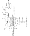
具体的に、この気液分離器43は、図2に示すように、分離器本体50と、分離器本体50内に処理後流体を導入するための導入路51と、分離器本体50内における導入路51より上方に、当該分離器本体50内を上下に分割するように配置される第1のデミスタ52aとを備えている。
このとき、導入路51は分離器本体50に対し、処理後流体を分離器本体50内の下方に向けて導入するように設けられていることが好ましい。これにより、導入された処理後流体のうち、液体成分は下方に滴下し、気体成分は上方に上昇するように、重力分離させることができるようになっている。
なお、ここで、導入路51は、下方に向けてらせん状に設けることが好ましい。このようにすることで、導入路51は、処理後流体の導入時に当該処理後流体を分離器本体50内の内壁面に沿って導入できるので、この処理後流体に含まれるタールやスカムと呼ばれるガスでできた泡が、飛沫の状態で飛び散るのを未然に回避できるようになっている。
また、第1のデミスタ52aは、金たわし、または金属網を積層したものからなり、分離器本体50内に導入される処理後流体のうち、前述の気体成分の通過を許可すると共に、液体成分の通過を阻止する。換言すれば、第1のデミスタ52aは、処理後流体から分離された気体成分を通過させ、液体成分を阻止することで、当該液体成分に含有される活性炭、無機物、タール、スカム等を捕集できるようになっている。
また、気液分離器43は、第1のデミスタ52aより上方に配置され、当該第1のデミスタ52aに向かって洗浄流体を噴射する洗浄ノズル53と、この洗浄ノズル53より上方に設けられ、分離器本体50内から重力分離した前述の気体成分を抜き出すガス抜出口54とを備えている。
第1のデミスタ52aでは、前述の活性炭、無機物、タール、スカム等を捕集することで汚れが生じる。そのため、洗浄ノズル53から第1のデミスタ52aに向かって洗浄流体を噴射することで洗浄できるようになっている。このとき、第1のデミスタ52aと洗浄ノズル53との間には、飛散防止部としての例えばドーナツ形状の平板部材からなる邪魔板59が、分離器本体50の内壁に密着して(例えば、溶接されて)設けられることが好ましい。これにより、洗浄ノズル53から噴出される洗浄流体の飛沫によって、第1のデミスタ52aに捕集された液体成分(特に、活性炭、無機物、タール、スカム等)が分離器本体50内の上方へ向かって飛散するのを防止することが可能となる。
ガス抜出口54には、ガス流路55が連通されており、当該ガス流路55には、ここを流れる前述の気体成分の圧力を調整する背圧弁などの圧力調整弁56が設けられている。この圧力調整弁56は、内部にばねを有する自圧式の調整弁からなり、一定の圧力になると開状態となり、分離器本体50内の圧力を一定範囲内に保つ機構として動作するようになっている。
なお、ガス抜出口54の近傍には、第1のデミスタ52aと同様の構造の第2のデミスタ52bが設けられることが好ましい。これにより、第1のデミスタ52aや邪魔板59を掻い潜り上ってくる液体成分(特に、活性炭、無機物、タール、スカム等)を捕集し、当該液体成分が分離器本体50内から抜き出される気体成分に随伴してガス流路55内を流通するのを、比較的流速が遅い分離器本体50内部において効果的に防止することが可能となる。
また、ガス流路55には、圧力調整弁56より上流側にガスフィルター60が設けられることが好ましい。これにより、ガス流路55を流れる気体成分に万一、液体成分が含有された場合においても、当該液体成分(特に、活性炭、無機物、タール、スカム等)を捕集することができるようになっている。
さらに、分離器本体50の下部には、前述の重力分離された液体成分を排出するための排出口57が設けられており、この排出口57には、分離器本体50内の気体成分の排出を防止する機構としての2つのゲート弁43a,43bが設けられた液体成分の排出路である排出配管58が連通されている。このとき、排出配管58には、2つのゲート弁43a,43bが設けられており、前述の液体成分を排出する際、まず上方のゲート弁43aのみを開状態とし、下方のゲート弁43bとの間に液体成分を溜めた状態にしたら上方のゲート弁43aを閉状態とする。そして、この後、下方のゲート弁43bのみを開状態とし、前記液体成分を排出する。このようにすることで、分離器本体50内が大気圧よりも高い圧力(例えば、0.3~0.5MPa)となっている場合であっても、内部の圧力や気体成分(生成ガス)を逃すことなく、液体成分を効率的に排出できるようになっている。
以上、説明したように、本実施形態のガス化システム10では、気液分離器43の分離器本体50内に処理後流体を導入するための導入路51より上方に、当該分離器本体50内を上下に分割するように配置される第1のデミスタ52aを備え、分離器本体50内に導入される処理後流体のうち、前述の気体成分の通過を許可すると共に、液体成分の通過を阻止するようにした。これにより、第1のデミスタ52aでは、処理後流体から分離された気体成分を通過させ、液体成分を阻止することで、当該液体成分に含有される活性炭、無機物、タール、スカム等を捕集できるので、気液分離器43から生成ガスを抜き出すガス流路55への活性炭、無機物等の固体成分や、タール、スカム等の粘性流体の流入を防止して、これら固体成分や粘性流体による目詰まりに起因したガス流路55の閉塞を未然に回避できる。かくして、ガス流路55におけるガスの通りを確保することができる。
このとき、気液分離器43は、ガス抜出口54近傍に第2のデミスタを設けるようにしてもよい。これにより、洗浄ノズル53から第1のデミスタ52aに向かって噴射される洗浄流体の飛沫や、それに起因して飛散する前記液体成分(特に、活性炭、無機物、タール、スカム等)が、比較的流速が遅い分離器本体50内部において、ガス抜出口54からガス流路55へと流下するのを効果的に防止することができる。
また、気液分離器43は、第1のデミスタ52aと洗浄ノズル53との間に邪魔板59を設けるようにしてもよい。これにより、洗浄ノズル53から噴出される洗浄流体の飛沫によって、第1のデミスタ52aに捕集された液体成分(特に、活性炭、無機物、タール、スカム等)が、分離器本体50内の上方へ向かって飛散するのを防止することができる。
さらに、気液分離器43は、ガス流路55の圧力調整弁56よりも上流側にガスフィルター60を設けるようにしてもよい。これにより、ガス流路55を流れる気体成分に万一、液体生成が含有された場合においても、この液体成分を捕集することができる。
さらに、気液分離器43は、導入路51が分離器本体50に対し、処理後流体を分離器本体50内の下方に向けて導入するように設けられることが好ましい。これにより、導入された処理後流体のうち、液体成分は下方に滴下し、気体成分は上方に上昇するように、重力分離させることができる。
しかも、導入路51を、下方に向けてらせん状に設けることで、導入路51は、処理後流体の導入時に当該処理後流体を分離器本体50内の内壁面に沿って導入できるので、この処理後流体に含まれるタールやスカムと呼ばれるガスでできた泡が、飛沫の状態で飛び散るのを未然に回避できる。
また、気液分離器43は、排出口57に連通され、分離器本体50内の気体成分の排出を防止して液体成分を排出する機構として、2つのゲート弁43a,43bを有する排出路58を設けるようにしてもよい。これにより、分離器本体50内が大気圧よりも高い圧力(例えば、0.3~0.5MPa)となっている場合であっても、内部の圧力や気体成分(生成ガス)を逃すことなく、液体成分を効率的に排出できる。
なお、本実施形態では図示省略しているが、本ガス化システム10に、ガスタンク44に貯えられた生成ガス(燃料ガス)を燃料として利用することで発電する発電装置を備えるようにしてもよい。この場合、発電装置は、例えば、ガスエンジン(レシプロエンジン、ロータリーエンジン)、蒸気タービン、スターリングエンジン、燃料電池などの既存の装置を広く適用できる。そして、本ガス化システム10により得られた燃料ガスを用いて、ガスエンジンによる発電を行うことにより、電力と排熱を得ることができるので、石炭、石油等の化石燃料の省資源化を図ることができる。
また、本ガス化システム10に予め含水性バイオマスを熱水処理する前処理装置(不図示)を備えることにより、バイオマスを高分子から低分子に分解することができるので、ガス化反応器33において処理されるバイオマスと水や非金属系触媒との接触効率を高め、タールやスカム等の発生の更なる抑制が可能となると共に、バイオマスから燃料ガスを効率よく生成できる。
10…ガス化システム、20…原料調製部、21…調製タンク、22…粉砕機、23…供給ポンプ、24…熱交換器導入ポンプ、30…熱処理部、31…熱交換器、32…加熱器、32a…燃焼装置、33…ガス化反応器、33a…燃焼装置、36…低温流路、37…高温流路、40…ガス処理部、41…減圧機構、42…冷却機構、43…気液分離器、43a…ゲート弁、43b…ゲート弁、44…ガスタンク、50…分離器本体、51…導入路、52a…第1のデミスタ、52b…第2のデミスタ、53…洗浄ノズル、54…ガス抜出口、55…ガス流路、56…圧力調整弁、57…排出口、58…排出路、59…邪魔板(飛散防止部)、60…ガスフィルター
Claims (8)
- 気体成分と、固体および粘性流体の少なくとも一方を含有する液体成分とを含む混合流体を重力分離する気液分離器であって、
分離器本体と、
前記分離器本体内に前記混合流体を導入するための導入路と、
前記分離器本体内における前記導入路より上方に、当該分離器本体内を上下に分割するように配置され、前記混合流体のうち、前記気体成分の通過を許可し、前記液体成分の通過を阻止する第1のデミスタと、
前記第1のデミスタより上方に配置され、当該第1のデミスタに向かって洗浄流体を噴射する洗浄ノズルと、
前記洗浄ノズルより上方に設けられ、前記分離器本体内から前記気体成分を抜き出すガス抜出口と、
前記ガス抜出口以降に設けられて、前記分離器内の圧力が一定範囲内に保たれる圧力調整機構と、
前記分離器本体の下部に滞留する前記重力分離された前記液体成分を排出するための排出口と、
を備えることを特徴する気液分離器。 - 前記ガス抜出口近傍に設けられ、前記洗浄流体の飛沫やそれに起因して飛散する前記液体成分が前記ガス抜出口から前記ガス抜出口以降へと流通するのを防止するための第2のデミスタを更に備える
ことを特徴とする請求項1に記載の気液分離器。 - 前記第1のデミスタと前記洗浄ノズルとの間に設けられ、前記洗浄ノズルから噴出される前記洗浄流体の飛沫によって、前記第1のデミスタに捕集された前記液体成分が前記分離器本体内の上方へ向かって飛散するのを防止するための飛散防止部を、更に備える
ことを特徴とする請求項1または2に記載の気液分離器。 - 前記ガス抜出口以降の前記圧力調整機構よりも上流側に設けられ、当該ガス抜出口以降を流れる前記気体成分に含まれ得る前記液体成分を捕集するためのガスフィルターを、更に備える
ことを特徴とする請求項1~3のいずれか一項に記載の気液分離器。 - 前記導入路が前記分離器本体に対し、前記混合流体を前記分離器本体内の下方に向けて導入するように設けられている
ことを特徴とする請求項1~4のいずれか一項に記載の気液分離器。 - 前記導入路は、前記下方に向けてらせん状に設けられている
ことを特徴とする請求項5に記載の気液分離器。 - 前記排出口に連通され、前記分離器内の気体成分の排出を防止する機構を有する排出路を更に備えている
ことを特徴とする請求項1~6のいずれか一項に記載の気液分離器。 - 前記請求項1~7のいずれか一項に記載の気液分離器を備え、
バイオマスを調製して生成されたスラリー体を、超臨界状態で分解処理する
ことを特徴とする超臨界水ガス化システム。
Priority Applications (2)
| Application Number | Priority Date | Filing Date | Title |
|---|---|---|---|
| PCT/JP2016/069295 WO2018003033A1 (ja) | 2016-06-29 | 2016-06-29 | 気液分離器およびそれを用いた超臨界水ガス化システム |
| JP2017506424A JP6163623B1 (ja) | 2016-06-29 | 2016-06-29 | 気液分離器およびそれを用いた超臨界水ガス化システム |
Applications Claiming Priority (1)
| Application Number | Priority Date | Filing Date | Title |
|---|---|---|---|
| PCT/JP2016/069295 WO2018003033A1 (ja) | 2016-06-29 | 2016-06-29 | 気液分離器およびそれを用いた超臨界水ガス化システム |
Publications (1)
| Publication Number | Publication Date |
|---|---|
| WO2018003033A1 true WO2018003033A1 (ja) | 2018-01-04 |
Family
ID=59308883
Family Applications (1)
| Application Number | Title | Priority Date | Filing Date |
|---|---|---|---|
| PCT/JP2016/069295 Ceased WO2018003033A1 (ja) | 2016-06-29 | 2016-06-29 | 気液分離器およびそれを用いた超臨界水ガス化システム |
Country Status (2)
| Country | Link |
|---|---|
| JP (1) | JP6163623B1 (ja) |
| WO (1) | WO2018003033A1 (ja) |
Families Citing this family (1)
| Publication number | Priority date | Publication date | Assignee | Title |
|---|---|---|---|---|
| CN107597810B (zh) * | 2017-10-18 | 2020-05-12 | 江苏瑞德斯环保科技有限公司 | 一种废漆渣减量干化工艺方法及其设备 |
Citations (6)
| Publication number | Priority date | Publication date | Assignee | Title |
|---|---|---|---|---|
| JPS5210973A (en) * | 1975-03-08 | 1977-01-27 | Nippon Air Filter Kk | Dust collecting apparatus |
| JPS57102300A (en) * | 1980-12-15 | 1982-06-25 | Kubota Ltd | Dehumidification method for waste gas in heat treatment of organic sludge |
| JPS643825Y2 (ja) * | 1981-04-24 | 1989-02-01 | ||
| JPH0417209Y2 (ja) * | 1986-12-16 | 1992-04-17 | ||
| JPH08159404A (ja) * | 1994-12-01 | 1996-06-21 | Mitsubishi Heavy Ind Ltd | 気水分離器 |
| JP2008246342A (ja) * | 2007-03-29 | 2008-10-16 | Hiroshima Univ | 気液分離器 |
Family Cites Families (1)
| Publication number | Priority date | Publication date | Assignee | Title |
|---|---|---|---|---|
| US20170066981A1 (en) * | 2014-03-05 | 2017-03-09 | The Chugoku Electric Power Co., Inc. | Gasification apparatus with supercritical fluid |
-
2016
- 2016-06-29 WO PCT/JP2016/069295 patent/WO2018003033A1/ja not_active Ceased
- 2016-06-29 JP JP2017506424A patent/JP6163623B1/ja active Active
Patent Citations (6)
| Publication number | Priority date | Publication date | Assignee | Title |
|---|---|---|---|---|
| JPS5210973A (en) * | 1975-03-08 | 1977-01-27 | Nippon Air Filter Kk | Dust collecting apparatus |
| JPS57102300A (en) * | 1980-12-15 | 1982-06-25 | Kubota Ltd | Dehumidification method for waste gas in heat treatment of organic sludge |
| JPS643825Y2 (ja) * | 1981-04-24 | 1989-02-01 | ||
| JPH0417209Y2 (ja) * | 1986-12-16 | 1992-04-17 | ||
| JPH08159404A (ja) * | 1994-12-01 | 1996-06-21 | Mitsubishi Heavy Ind Ltd | 気水分離器 |
| JP2008246342A (ja) * | 2007-03-29 | 2008-10-16 | Hiroshima Univ | 気液分離器 |
Also Published As
| Publication number | Publication date |
|---|---|
| JPWO2018003033A1 (ja) | 2018-06-28 |
| JP6163623B1 (ja) | 2017-07-12 |
Similar Documents
| Publication | Publication Date | Title |
|---|---|---|
| US7575613B2 (en) | Method and apparatus for producing methane from carbonaceous material | |
| RU2441900C2 (ru) | Устройство газификации и его применение | |
| JP6488364B2 (ja) | 超臨界水ガス化システム | |
| JP6573261B2 (ja) | 超臨界水ガス化システム | |
| JP6070906B1 (ja) | 超臨界水ガス化システムおよびガス化方法 | |
| JPWO2013094382A1 (ja) | 合成ガスの生成方法及び製造装置、並びに、液体燃料の合成方法及び合成装置 | |
| JP2014125577A (ja) | 生成ガスの製造方法、製造装置及びタール除去装置 | |
| RU2601159C2 (ru) | Аппарат для получения биогаза разложением органического материала | |
| JP6163623B1 (ja) | 気液分離器およびそれを用いた超臨界水ガス化システム | |
| US8741181B2 (en) | Method and apparatus for treating a raw UCG product stream | |
| JP5865553B1 (ja) | 超臨界流体によるガス化装置 | |
| CN103820156B (zh) | 一种褐煤气化微型反应装置 | |
| KR102738784B1 (ko) | 타르 개질기 일체형 가스화기 | |
| JP4997546B2 (ja) | 超臨界水バイオマスガス化装置及びそれを含むシステム | |
| JPWO2016038724A1 (ja) | バイオマスガス化システムおよびバイオマスガス化方法 | |
| JPWO2015132923A1 (ja) | 超臨界流体によるガス化装置 | |
| MX2013013518A (es) | Cartucho multifuncional reemplazable en campo para conversion de desperdicios en combustible. | |
| JP6127215B2 (ja) | ガス化システム | |
| CN101421377B (zh) | 重质油轻质化装置及重质油轻质化方法 | |
| JP6108374B2 (ja) | バイオマススラリーをガス化する超臨界水ガス化システム | |
| US20250387729A1 (en) | Scraped-surface salt separator with a scraper plate which slides into a precipated-salt resolubilization zone and associated biomass gasification facility | |
| CA2818462A1 (en) | Macroapparatus for the production and treatment of gas obtained from mineral coal | |
| Tacconi | Gassificazione di biomasse, pulizia e condizionamento del gas prodotto per la produzione di biocombustibili ed energia | |
| WO2021132046A1 (ja) | ガス化システム | |
| ITMI20102156A1 (it) | Macroapparato per la produzione e il trattamento di gas |
Legal Events
| Date | Code | Title | Description |
|---|---|---|---|
| ENP | Entry into the national phase |
Ref document number: 2017506424 Country of ref document: JP Kind code of ref document: A |
|
| 121 | Ep: the epo has been informed by wipo that ep was designated in this application |
Ref document number: 16907266 Country of ref document: EP Kind code of ref document: A1 |
|
| NENP | Non-entry into the national phase |
Ref country code: DE |
|
| 122 | Ep: pct application non-entry in european phase |
Ref document number: 16907266 Country of ref document: EP Kind code of ref document: A1 |